SV9000 AF Drives — Motor Pump Enhanced Protection Applicationprof.usb.ve/bueno/Laboratorio/Manual...
60
MN04001002E For more information visit: www.eatonelectrical.com SV9000 AF Drives — Motor Pump Enhanced Protection Application Application Manual June 2004 Supersedes February 2001
Transcript of SV9000 AF Drives — Motor Pump Enhanced Protection Applicationprof.usb.ve/bueno/Laboratorio/Manual...
MN04001002E For more information visit:
www.eatonelectrical.com
SV9000 AF Drives — Motor Pump Enhanced Protection Application
Application Manual
June 2004Supersedes February 2001
Page ii (60) Motor Pump Enhanced Protection Application SV9000
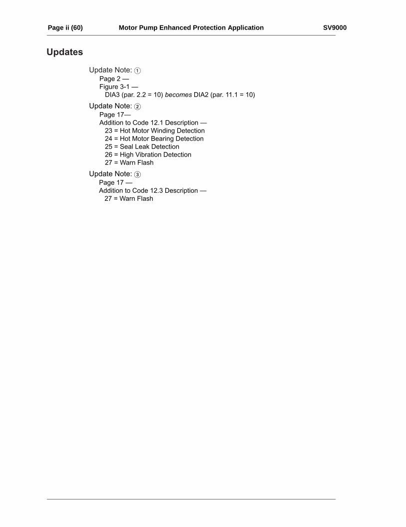
Updates
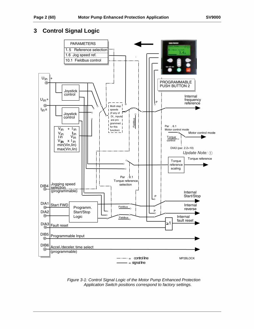
Update Note: 1Page 2 —Figure 3-1 — DIA3 (par. 2.2 = 10) becomes DIA2 (par. 11.1 = 10)
Update Note: 2
Addition to Code 12.1 Description — 23 = Hot Motor Winding Detection 24 = Hot Motor Bearing Detection 25 = Seal Leak Detection 26 = High Vibration Detection 27 = Warn Flash
Update Note: 3
Page 17 —
Page 17 — Addition to Code 12.3 Description — 27 = Warn Flash
Page iii Manual Title SV9000
Motor Pump EnhancedProtection Application
Contents1 General........................................................ 22 Control I/O ................................................... 23 Control Signal Logic .................................... 24 Parameter Group 0...................................... 3
4.1 Application Selection ............................ 34.2 Parameter Loading ............................... 34.3 Language .............................................. 3
5 Basic Parameters, Group 1 ......................... 45.1 Parameter Table ................................... 45.2 Description of Group 1 Parameters ...... 5
6 Special parameters, Groups 210............. 96.1 Parameter tables................................... 96.2 Description of Groups 2-10 Parameters
............................................................ 197 Fault Code................................................. 528 Monitoring Data ......................................... 529 SV9IOC103 Control Connections ............. 53
Page iv (60) Motor Pump Enhanced Protection Application SV9000
Page 1 (60) Motor Pump Enhanced Protection Application SV9000
1 GeneralThe Motor Pump Enhanced Protectionapplication is a modified version of the normalMulti-Purpose application. It has parameters fortorque control and for Fieldbus communication.The following fieldbuses are supported:Interbus, Modbus, LonWorks, CAN-bus(SDS, DeviceNet).
The frequency reference, the analog anddigital outputs have extra alternatives in theircontrol parameters, however, the source of thefree analog input can not be selected from theI/O Expander as in the Multi-Purpose IIapplication. Lastly, this application allows forup to four (4) additional custom inputs, faults,and fault indicators (when an additional I/Oboard is installed).
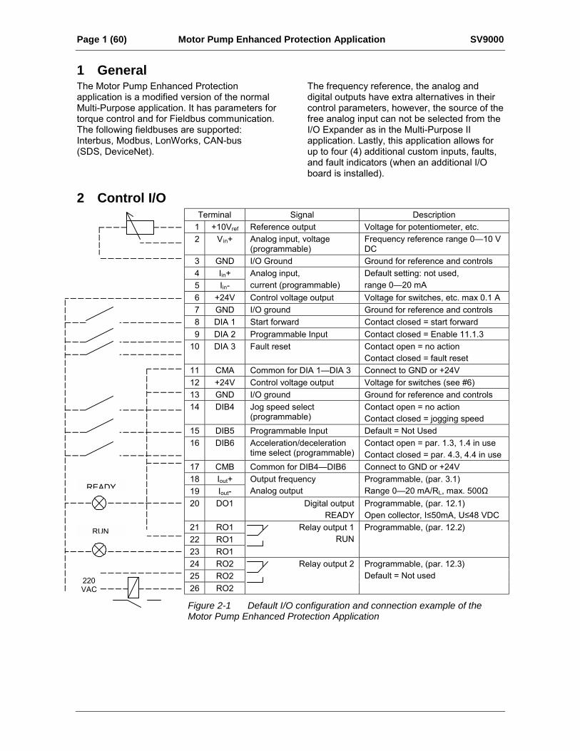
2 Control I/OTerminal Signal Description
1 +10Vref Reference output Voltage for potentiometer, etc.2 V in+ Analog input, voltage
(programmable)Frequency reference range 010 VDC
3 GND I/O Ground Ground for reference and controls4 Iin+5 Iin-
Analog input,current (programmable)
Default setting: not used,range 020 mA
6 +24V Control voltage output Voltage for switches, etc. max 0.1 A7 GND I/O ground Ground for reference and controls8 DIA 1 Start forward Contact closed = start forward9 DIA 2 Programmable Input Contact closed = Enable 11.1.3
10 DIA 3 Fault reset Contact open = no actionContact closed = fault reset
11 CMA Common for DIA 1DIA 3 Connect to GND or +24V12 +24V Control voltage output Voltage for switches (see #6)13 GND I/O ground Ground for reference and controls14 DIB4 Jog speed select
(programmable)Contact open = no actionContact closed = jogging speed
15 DIB5 Programmable Input Default = Not Used16 DIB6 Acceleration/deceleration
time select (programmable)Contact open = par. 1.3, 1.4 in useContact closed = par. 4.3, 4.4 in use
17 CMB Common for DIB4DIB6 Connect to GND or +24V18 Iout+19 Iout-
Output frequencyAnalog output
Programmable, (par. 3.1)Range 020 mA/RL, max. 500Ω
20 DO1 Digital outputREADY
Programmable, (par. 12.1)Open collector, I≤50mA, U≤48 VDC
21 RO122 RO123 RO1
Relay output 1RUN
Programmable, (par. 12.2)
24 RO225 RO226 RO2
Relay output 2 Programmable, (par. 12.3)Default = Not used
Figure 2-1 Default I/O configuration and connection example of theMotor Pump Enhanced Protection Application
READY
RUN
220VAC
Page 2 (60) Motor Pump Enhanced Protection Application SV9000
3 Control Signal Logic
DIB4
DIA1
DIA2
P
P
P
DIA3
MP2BLOCK
>1
DIB5
DIB6
Update Note: 1
Internalfrequencyreference
InternalStart/Stop
Internalfault reset
Internalreverse
= control line
= signal line
Programm.
Start/Stop
Logic
PROGRAMMABLEPUSH BUTTON 2
Multi step
speeds
(If any of
DI_ inputs
are pro
grammed
for this
function)
Joystickcontrol
Joystickcontrol
Jogging speedselection(programmable)
ARAMETERS
1. 5 Reference selection
1.6 Jog speed ref.
10.1 Fieldbus control
Fault reset
Programmable Input
Accel./deceler. time select(programmable)
Start FWD
Uin +
Iin±
in + I
in IIV in x
Iin
inmin(Vin,Iin)
V inV I
I inin
max(Vin,Iin)
Par . 9.1
Torque reference
selection
Par . 6.1
Motor control mode
Torque
reference
scaling
Torque reference
Motor control mode
Torque
control
DIA3 (par. 2.2=10)
Fieldbus
Fieldbus
Fieldbus
Uin+
P
.
ininV
Figure 3-1: Control Signal Logic of the Motor Pump Enhanced ProtectionApplication Switch positions correspond to factory settings.

SV9000 Motor Pump Enhanced Protection Application Page 3 (60)
4 Parameter Group 0Number Parameter Range Step Default Customer Description
0.1 Applicationselection 0-7 1 0
0 = Motor Pump Enhanced Protection(loaded special application)
1 = Basic Application2 = Standard Application3 = Local/Remote4 = Multi-step Speed Application5 = PI-control Application6 = Multi-purpose Control Application7 = Pump and Fan control Application
0.2 ParameterLoading 0-5 1 0
0 = Loading ready / Select loading1 = Load default setting2 = Read up parameters to user's set3 = Load down user's set parameters4 = Read parameters up to the panel
(possible only with the graphicalpanel)
5 = Load down parameters from the panel(possible only with graphical panel)
0.3 LanguageSelection 0 0 = English
4.1 Application SelectionWith this parameter the active application can be selected. If the device has been ordered from thefactory equipped with the Multipurpose II application this has been loaded in the unit as application 0.The application has also been set active at the factory. However, check that the value of theparameter 0.1 is zero when you want to use Motor Pump EP.
If the application is loaded later it has to be activated after loading by setting the value of parameter0.1 to zero.
4.2 Parameter LoadingSee User's Manual chapter 11.
4.3 LanguageWith this parameter, the language of the graphical panel can be selected.

Page 4 (60) Motor Pump Enhanced Protection Application SV9000
5 Basic Parameters, Group 15.1 Parameter TableCode Parameter Range Step Default Custom Description Page1.1 Minimum frequency 0120/500 Hz 1 Hz 0 Hz 51.2 Maximum
frequency0120/500 Hz 1 Hz 50 Hz * 5
1.3 Acceleration time 1 0.13000 s 0.1 s 3 s Time from fmin (1. 1) to fmax (1. 2) 51.4 Deceleration time 1 0.13000 0.1 s 3 s Time from fmax (1. 2) to fmin (1. 1) 5
0 = Vin 3 = Vin - Iin1 = Iin 4 = Iin - Vin2 = Vin + Iin 5 = Vin * Iin6 = Vin joystick control7 = Iin joystick control8 = Signal from internal motor pot.9 = Signal from internal motor pot.
reset if SV9000 unit is stopped10 = Signal from internal motor pot.
(stored in memory over utilitybreak)
11 = Min (Vin, Iin)12 = Max (Vin, Iin)
1.5 Referenceselection
013
13 = Panel reference r1
5
1.6 Jog speedreference
fmin fmax 0.1 Hz 5 Hz 6
1.7 Current limit 0.12.5 x InSV9
0.1 A 1.5 xInSV9
Output current limit [A] of the unit 6
1.8 V/Hz ratio selection 02 1 0 0 = Linear1 = Squared2 = Programmable V/Hz ratio
7
1.9 V/Hz optimization 01 1 0 0 = None1 = Automatic torque boost
8
1.10 Nominal voltage ofthe motor
180690 1 V 230 V380 V480 V575 V
Voltage code 2Voltage code 4Voltage code 5Voltage code 6
8
1.11 Nominal frequencyof the motor
30500 Hz 1 Hz 60 Hz fn on the rating plate of the motor 8
1.12 Nominal speed ofthe motor
120000 rpm 1 rpm 1440rpm
nn on the rating plate of the motor 8
1.13 Nominal current ofthe motor
2.5 x InSV9 0.1 A InSV9 In on the rating plate of the motor 8
1.14 Supply voltage 180250380440380500525690
230 V380 V480 V575 V
Voltage code 2Voltage code 4Voltage code 5Voltage code 6
8
1.15 Parameter conceal 01 1 0 Visibility of the parameters:0 = All parameter groups visible1 = Only group 1 is visible
8
1.16 Parameter valuelock
01 1 0 Disables parameter changes:0 = Changes enabled1 = Changes disabled
8
* If 1.2 >motor synchr. speed, check suitability for motor and drive system.Note! = Parameter value can be changed only when the frequency converter is stopped.
Table 5-1 Group 1 Basic Parameters.
SV9000 Motor Pump Enhanced Protection Application Page 5 (60)
5.2 Description of Group 1 Parameters1.1 Minimum frequency1.2 Maximum frequency
Defines frequency limits of the frequency converter. The default maximum value forparameters 1.1 and 1.2 is 120 Hz. By setting 1.2 = 120 Hz when the device is stopped(RUN indicator not lit) the maximum value of parameters 1.1 and 1.2 is changed to500 Hz. At the same time the panel reference resolution is changed from 0.01 Hz to0.1 Hz. Changing the maximum value from 500 Hz to 120 Hz is done by setting parameter1.2 = 119 Hz when the device is stopped.
1.3 Acceleration time 11.4 Deceleration time 1
These limits correspond to the time required for the output frequency to accelerate fromthe set minimum frequency (par. 1.1) to the set maximum frequency (par. 1.2).
1.5 Reference selection0 Analog voltage reference from terminals 23, e.g. a potentiometer
1 Analog current reference from terminals 45, e.g. a transducer.
2 Reference is formed by adding the values of the analog inputs
3 Reference is formed by subtracting the voltage input (Vin) value from the current input(Iin) value
4 Reference is formed by subtracting the current input (Iin) value from the voltage input(Vin) value
5 Reference is the formed by multiplying the values of the analog inputs
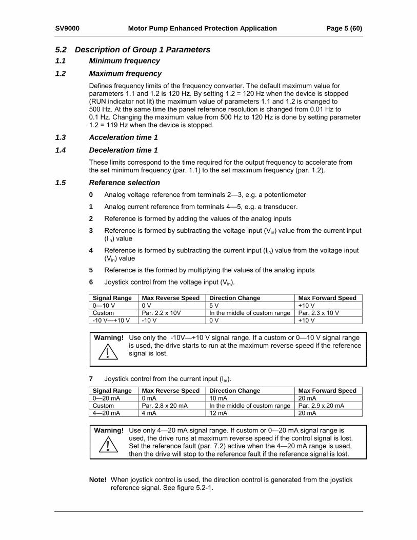
6 Joystick control from the voltage input (Vin).
Signal Range Max Reverse Speed Direction Change Max Forward Speed010 V 0 V 5 V +10 VCustom Par. 2.2 x 10V In the middle of custom range Par. 2.3 x 10 V-10 V+10 V -10 V 0 V +10 V
Warning! Use only the -10V+10 V signal range. If a custom or 010 V signal rangeis used, the drive starts to run at the maximum reverse speed if the referencesignal is lost.
7 Joystick control from the current input (Iin).
Signal Range Max Reverse Speed Direction Change Max Forward Speed020 mA 0 mA 10 mA 20 mACustom Par. 2.8 x 20 mA In the middle of custom range Par. 2.9 x 20 mA420 mA 4 mA 12 mA 20 mA
Warning! Use only 420 mA signal range. If custom or 020 mA signal range isused, the drive runs at maximum reverse speed if the control signal is lost.Set the reference fault (par. 7.2) active when the 420 mA range is used,then the drive will stop to the reference fault if the reference signal is lost.
Note! When joystick control is used, the direction control is generated from the joystickreference signal. See figure 5.2-1.
Page 6 (60) Motor Pump Enhanced Protection Application SV9000
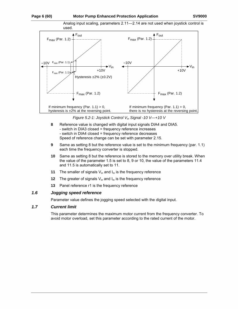
Analog input scaling, parameters 2.112.14 are not used when joystick control isused.
Fout
–10V
+10VVin
Fmax (Par. 1.2)
Fmax (Par. 1.2)
Fmin (Par. 1.1)
Fmin (Par. 1.1)
Hysteresis ±2% (±0.2V)
If minimum frequency (Par. 1.1) > 0,hysteresis is ±2% at the reversing point.
Fout
–10V
+10VVin
Fmax (Par. 1.2)
Fmax (Par. 1.2)
If minimum frequency (Par. 1.1) = 0,there is no hysteresis at the reversing point.
Figure 5.2-1: Joystick Control Vin Signal -10 V—+10 V
8 Reference value is changed with digital input signals DIA4 and DIA5.- switch in DIA3 closed = frequency reference increases- switch in DIA4 closed = frequency reference decreasesSpeed of reference change can be set with parameter 2.15.
9 Same as setting 8 but the reference value is set to the minimum frequency (par. 1.1)each time the frequency converter is stopped.
10 Same as setting 8 but the reference is stored to the memory over utility break. Whenthe value of the parameter 1.5 is set to 8, 9 or 10, the value of the parameters 11.4and 11.5 is automatically set to 11.
11 The smaller of signals Vin and Iin is the frequency reference
12 The greater of signals Vin and Iin is the frequency reference
13 Panel reference r1 is the frequency reference
1.6 Jogging speed referenceParameter value defines the jogging speed selected with the digital input.
1.7 Current limitThis parameter determines the maximum motor current from the frequency converter. Toavoid motor overload, set this parameter according to the rated current of the motor.
SV9000 Motor Pump Enhanced Protection Application Page 7 (60)
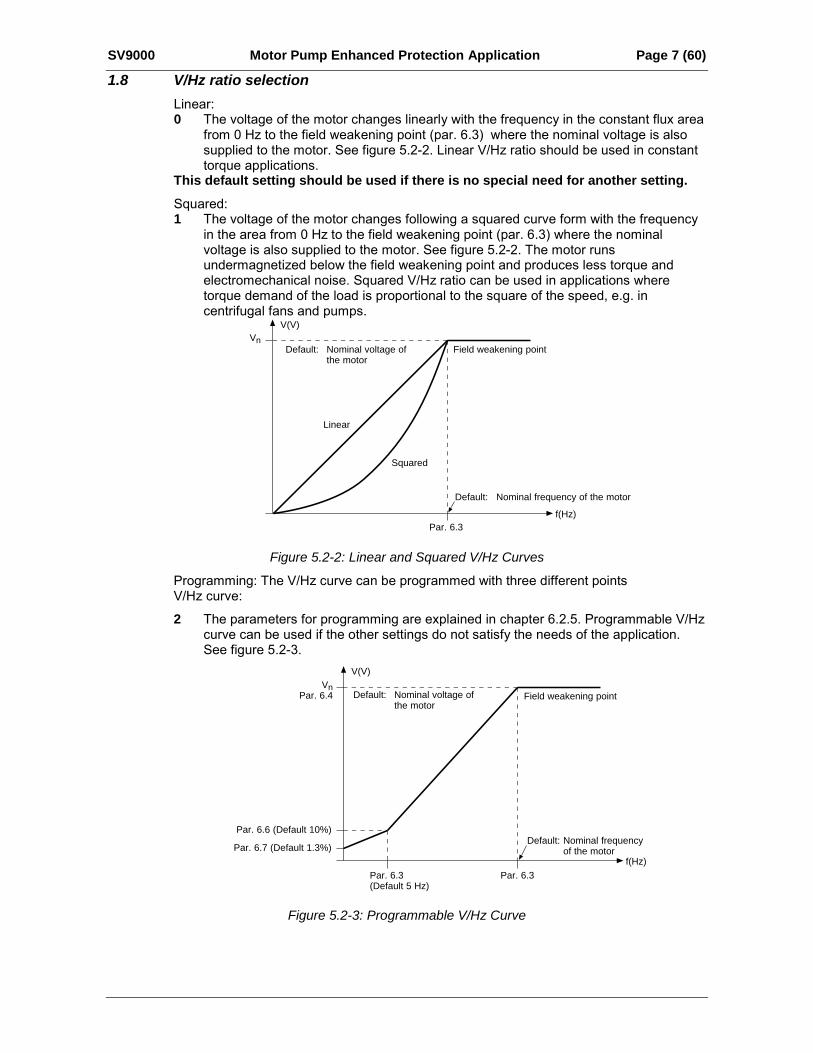
1.8 V/Hz ratio selectionLinear:0 The voltage of the motor changes linearly with the frequency in the constant flux area
from 0 Hz to the field weakening point (par. 6.3) where the nominal voltage is alsosupplied to the motor. See figure 5.2-2. Linear V/Hz ratio should be used in constanttorque applications.
This default setting should be used if there is no special need for another setting.Squared:1 The voltage of the motor changes following a squared curve form with the frequency
in the area from 0 Hz to the field weakening point (par. 6.3) where the nominalvoltage is also supplied to the motor. See figure 5.2-2. The motor runsundermagnetized below the field weakening point and produces less torque andelectromechanical noise. Squared V/Hz ratio can be used in applications wheretorque demand of the load is proportional to the square of the speed, e.g. incentrifugal fans and pumps.
Vn
V(V)
f(Hz)
Default: Nominal voltage ofthe motor
Default: Nominal frequency of the motor
Field weakening point
Squared
Linear
Par. 6.3
Figure 5.2-2: Linear and Squared V/Hz Curves
Programming: The V/Hz curve can be programmed with three different pointsV/Hz curve:
2 The parameters for programming are explained in chapter 6.2.5. Programmable V/Hzcurve can be used if the other settings do not satisfy the needs of the application.See figure 5.2-3.
VnPar. 6.4
V(V)
f(Hz)
Default: Nominal voltage ofthe motor
Default: Nominal frequencyof the motor
Field weakening point
Par. 6.3Par. 6.3(Default 5 Hz)
Par. 6.7 (Default 1.3%)
Par. 6.6 (Default 10%)
Figure 5.2-3: Programmable V/Hz Curve
Page 8 (60) Motor Pump Enhanced Protection Application SV9000
1.9 V/Hz optimizationAutomatic: The voltage to the motor changes automatically which makes the torque motor produce sufficient torque to start and run at low frequencies. The boost voltageincrease depends on the motor type and power.
Automatic torque boost can be used in applications where starting torque due to startingfriction is high, e.g. in conveyors.
Note! In high torque / low speed applications, it is likely the motor will overheat. If the motor has torun a prolonged time under these conditions, special attention must be paid to cooling themotor. Use external cooling for the motor if the temperature tends to rise too high.
1.10 Nominal voltage of the motorFind this value Vn on the rating plate of the motor.This parameter sets the voltage at the field weakening point, parameter 6.4, to100% x Vnmotor.
1.11 Nominal frequency of the motorFind this value fn on the rating plate of the motor.This parameter sets the field weakening point, parameter 6.3, to the same value.
1.12 Nominal speed of the motorFind this value nn on the rating plate of the motor.
1.13 Nominal current of the motorFind this value In on the rating plate of the motor.
1.14 Supply voltageSet the parameter value according to the nominal voltage of the supply.Values are predefined for voltage codes 2, 4, 5 and 6. See table 5-1.
1.15 Parameter concealDefines which parameter groups are available:
0 = all parameter groups are visible1 = only group 1 is visible
1.16 Parameter value lockAllows parameter value changes:
0 = parameter value changes enabled1 = parameter value changes disabled
SV9000 Motor Pump Enhanced Protection Application Page 9 (60)
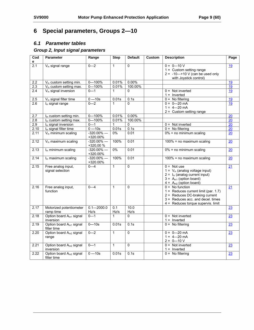
6 Special parameters, Groups 2—10
6.1 Parameter tablesGroup 2, Input signal parameters
Code
Parameter Range Step Default Custom Description Page
2.1 Vin signal range 02 1 0 0 = 010 V1 = Custom setting range2 = -10+10 V (can be used only
with Joystick control)
19
2.2 Vin custom setting min. 0100% 0.01% 0.00% 192.3 Vin custom setting max. 0100% 0.01% 100.00% 192.4 Vin signal inversion 01 1 0 0 = Not inverted
1 = Inverted19
2.5 Vin signal filter time 0 10s 0.01s 0.1s 0 = No filtering 192.6 Iin signal range 02 1 0 0 = 020 mA
1 = 420 mA2 = Custom setting range
19
2.7 Iin custom setting min. 0100% 0.01% 0.00% 202.8 Iin custom setting max. 0100% 0.01% 100.00% 202.9 Iin signal inversion 01 1 0 0 = Not inverted 202.10 Iin signal filter time 0 10s 0.01s 0.1s 0 = No filtering 202.11 Vin minimum scaling -320.00%
+320.00%0% 0.01 0% = no minimum scaling 20
2.12 Vin maximum scaling -320.00% +320,00 %
100% 0.01 100% = no maximum scaling 20
2.13 Iin minimum scaling -320.00% +320.00%
0% 0.01 0% = no minimum scaling 20
2.14 Iin maximum scaling -320.00% +320.00%
100% 0.01 100% = no maximum scaling 20
2.15 Free analog input,signal selection
04 1 0 0 = Not use1 = Vin (analog voltage input)2 = Iin (analog current input)3 = Ain1 (option board)4 = Ain2 (option board)
21
2.16 Free analog input,function
04 1 0 0 = No function1 = Reduces current limit (par. 1.7)2 = Reduces DC-braking current3 = Reduces acc. and decel. times4 = Reduces torque supervis. limit
21
2.17 Motorized potentiometerramp time
0.12000.0Hz/s
0.1Hz/s
10.0Hz/s
23
2.18 Option board Ain1 signalinversion
01 1 0 0 = Not inverted1 = Inverted
23
2.19 Option board Ain1 signalfilter time
010s 0.01s 0.1s 0 = No filtering 23
2.20 Option board Ain2 signalrange
02 1 0 0 = 020 mA1 = 420 mA2 = 010 V
23
2.21 Option board Ain2 signalinversion
01 1 0 0 = Not inverted1 = Inverted
23
2.22 Option board Ain2 signalfilter time
0 10s 0.01s 0.1s 0 = No filtering 23
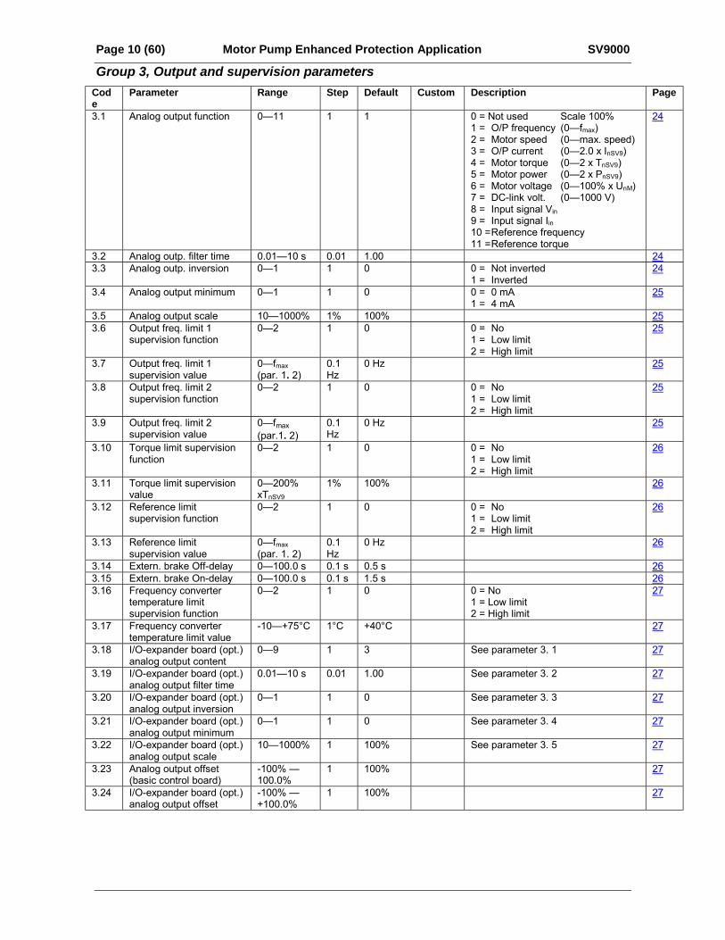
Page 10 (60) Motor Pump Enhanced Protection Application SV9000
Group 3, Output and supervision parametersCode
Parameter Range Step Default Custom Description Page
3.1 Analog output function 011 1 1 0 = Not used Scale 100%1 = O/P frequency (0fmax)2 = Motor speed (0max. speed)3 = O/P current (02.0 x InSV9)4 = Motor torque (02 x TnSV9)5 = Motor power (02 x PnSV9)6 = Motor voltage (0100% x UnM)7 = DC-link volt. (01000 V)8 = Input signal Vin9 = Input signal Iin10 =Reference frequency11 =Reference torque
24
3.2 Analog outp. filter time 0.0110 s 0.01 1.00 243.3 Analog outp. inversion 01 1 0 0 = Not inverted
1 = Inverted24
3.4 Analog output minimum 01 1 0 0 = 0 mA1 = 4 mA
25
3.5 Analog output scale 101000% 1% 100% 253.6 Output freq. limit 1
supervision function02 1 0 0 = No
1 = Low limit2 = High limit
25
3.7 Output freq. limit 1supervision value
0fmax(par. 1. 2)
0.1Hz
0 Hz 25
3.8 Output freq. limit 2supervision function
02 1 0 0 = No1 = Low limit2 = High limit
25
3.9 Output freq. limit 2supervision value
0fmax(par.1. 2)
0.1Hz
0 Hz 25
3.10 Torque limit supervisionfunction
02 1 0 0 = No1 = Low limit2 = High limit
26
3.11 Torque limit supervisionvalue
0200%xTnSV9
1% 100% 26
3.12 Reference limitsupervision function
02 1 0 0 = No1 = Low limit2 = High limit
26
3.13 Reference limitsupervision value
0fmax(par. 1. 2)
0.1Hz
0 Hz 26
3.14 Extern. brake Off-delay 0100.0 s 0.1 s 0.5 s 263.15 Extern. brake On-delay 0100.0 s 0.1 s 1.5 s 263.16 Frequency converter
temperature limitsupervision function
02 1 0 0 = No1 = Low limit2 = High limit
27
3.17 Frequency convertertemperature limit value
-10+75°C 1°C +40°C 27
3.18 I/O-expander board (opt.)analog output content
09 1 3 See parameter 3. 1 27
3.19 I/O-expander board (opt.)analog output filter time
0.0110 s 0.01 1.00 See parameter 3. 2 27
3.20 I/O-expander board (opt.)analog output inversion
01 1 0 See parameter 3. 3 27
3.21 I/O-expander board (opt.)analog output minimum
01 1 0 See parameter 3. 4 27
3.22 I/O-expander board (opt.)analog output scale
101000% 1 100% See parameter 3. 5 27
3.23 Analog output offset(basic control board)
-100% 100.0%
1 100% 27
3.24 I/O-expander board (opt.)analog output offset
-100% +100.0%
1 100% 27

SV9000 Motor Pump Enhanced Protection Application Page 11 (60)
Group 4, Drive Control ParametersCode Parameter Range Step Default Custom Description Page4.1 Acc./Dec. ramp 1 shape 010 s 0.1 s 0 0 = Linear
>0 = S-curve acc./dec. time 28
4.2 Acc./Dec. ramp 2 shape 010 s 0.1 s 0 0 = Linear>0 = S-curve acc./dec. time 28
4.3 Acceleration time 2 0.13000 s 0.1 s 10 s 284.4 Deceleration time 2 0.13000 s 0.1 s 10 s 28
4.5 Brake chopper 01 1 00 = Brake chopper not in use1 = Brake chopper in use2 = External brake chopper
28
4.6 Start function 01 1 0 0 = Ramp1 = Flying start 29
4.7 Stop function 01 1 0 0 = Coasting1 = Ramp 29
4.8 DC-braking current 0.151.5x InSV9 (A) 0.1 A 0.5 x
InSV929
4.9 DC-braking time at Stop 0250.0 s 0.1 s 0 s 0 = DC-brake is off at Stop 29
4.10 Execute freq. of DC-brake during ramp Stop 0.110 Hz 0.1
Hz 1.5 Hz 30
4.11 DC-brake time at Start 0.025.0 s 0.1 s 0 s 0 = DC-brake is off at Start 30
4.12 Multi-step speedreference 1
fmin fmax(1. 1) (1. 2)
0.1Hz 10 Hz 31
4.13 Multi-step speedreference 2
fmin fmax(1. 1) (1. 2)
0.1Hz 15 Hz 31
4.14 Multi-step speedreference 3
fmin fmax(1. 1) (1. 2)
0.1Hz 20 Hz 31
4.15 Multi-step speedreference 4
fmin fmax(1. 1) (1. 2)
0.1Hz 25 Hz 31
4.16 Multi-step speedreference 5
fmin fmax(1. 1) (1. 2)
0.1Hz 30 Hz 31
4.17 Multi-step speedreference 6
fmin fmax(1. 1) (1. 2)
0.1Hz 40 Hz 31
4.18 Multi-step speedreference 7
fmin fmax(1. 1) (1.2)
0.1Hz 50 Hz 31
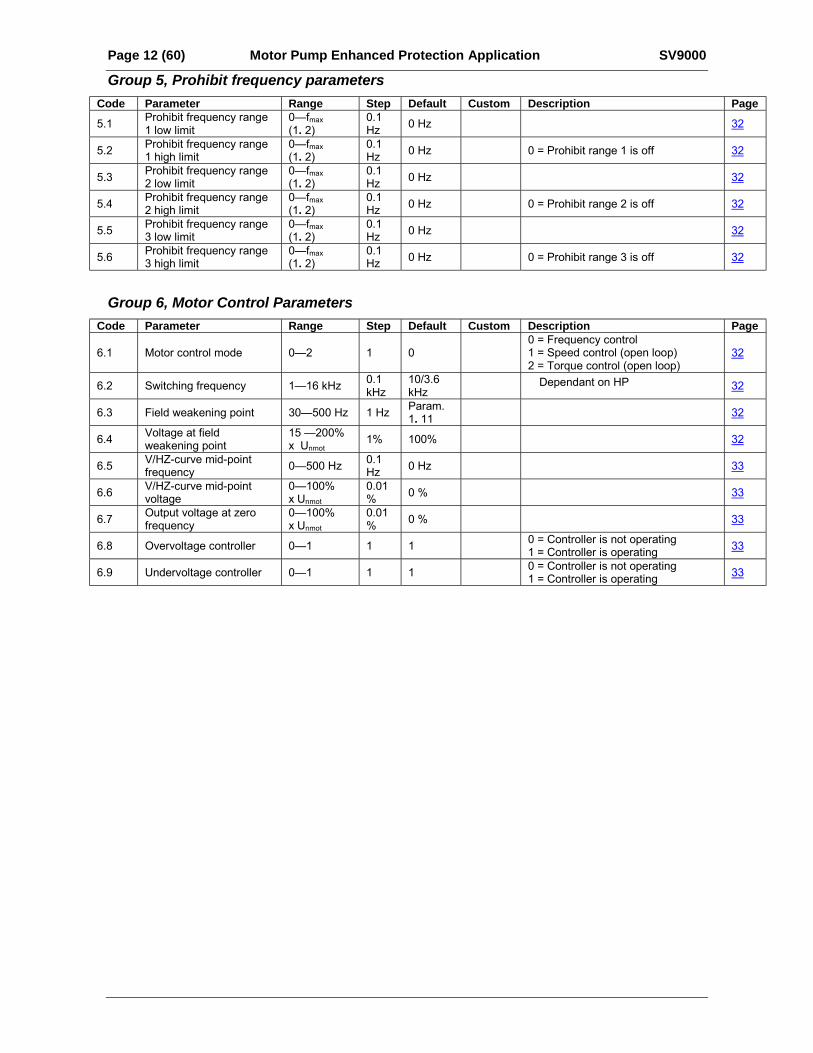
Page 12 (60) Motor Pump Enhanced Protection Application SV9000
Group 5, Prohibit frequency parametersCode Parameter Range Step Default Custom Description Page5.1 Prohibit frequency range
1 low limit0fmax(1. 2)
0.1Hz 0 Hz 32
5.2 Prohibit frequency range1 high limit
0fmax(1. 2)
0.1Hz 0 Hz 0 = Prohibit range 1 is off 32
5.3 Prohibit frequency range2 low limit
0fmax(1. 2)
0.1Hz 0 Hz 32
5.4 Prohibit frequency range2 high limit
0fmax(1. 2)
0.1Hz 0 Hz 0 = Prohibit range 2 is off 32
5.5 Prohibit frequency range3 low limit
0fmax(1. 2)
0.1Hz 0 Hz 32
5.6 Prohibit frequency range3 high limit
0fmax(1. 2)
0.1Hz 0 Hz 0 = Prohibit range 3 is off 32
Group 6, Motor Control ParametersCode Parameter Range Step Default Custom Description Page
6.1 Motor control mode 02 1 00 = Frequency control1 = Speed control (open loop)2 = Torque control (open loop)
32
6.2 Switching frequency 116 kHz 0.1kHz
10/3.6kHz
Dependant on HP 32
6.3 Field weakening point 30500 Hz 1 Hz Param.1. 11 32
6.4 Voltage at fieldweakening point
15 200%x Unmot
1% 100% 32
6.5 V/HZ-curve mid-pointfrequency 0500 Hz 0.1
Hz 0 Hz 33
6.6 V/HZ-curve mid-pointvoltage
0100%x Unmot
0.01% 0 % 33
6.7 Output voltage at zerofrequency
0100%x Unmot
0.01% 0 % 33
6.8 Overvoltage controller 01 1 1 0 = Controller is not operating1 = Controller is operating 33
6.9 Undervoltage controller 01 1 1 0 = Controller is not operating1 = Controller is operating 33
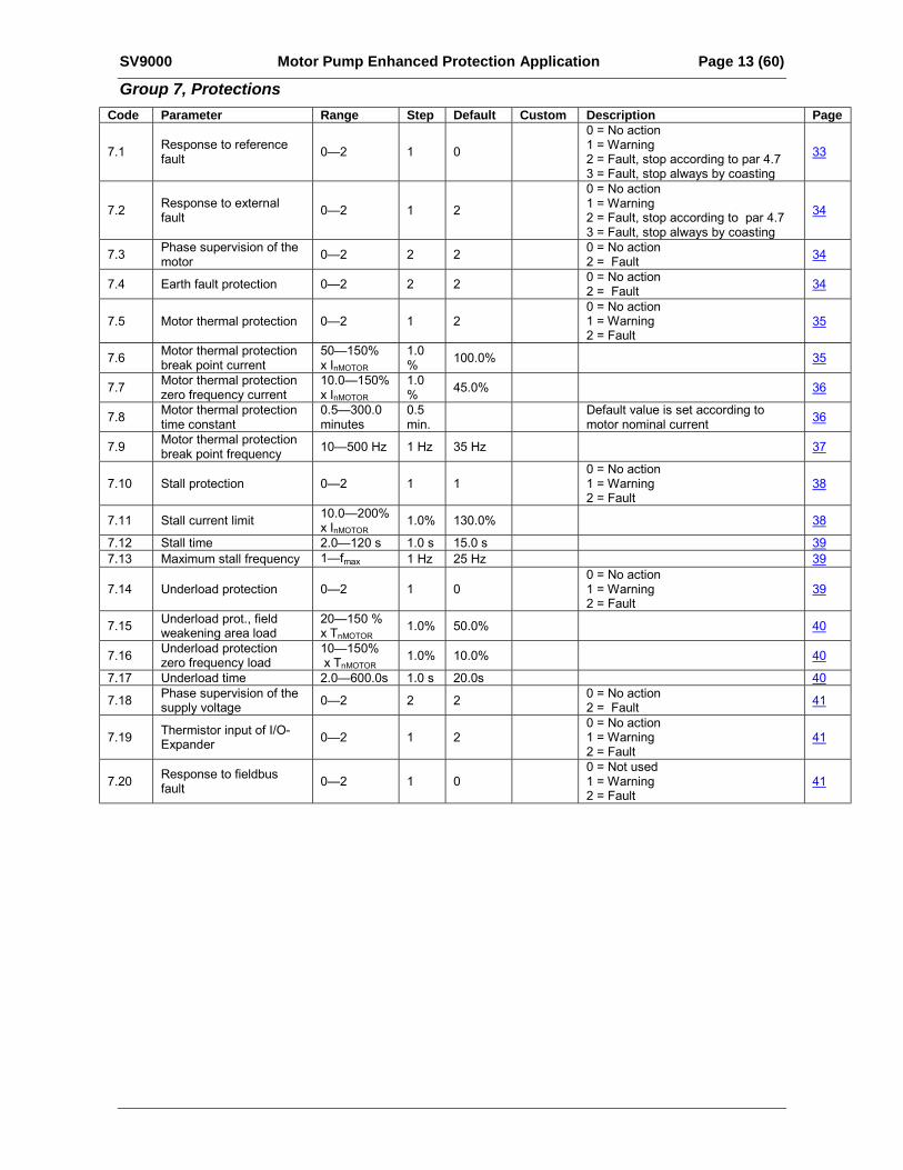
SV9000 Motor Pump Enhanced Protection Application Page 13 (60)
Group 7, ProtectionsCode Parameter Range Step Default Custom Description Page
7.1 Response to referencefault 02 1 0
0 = No action1 = Warning2 = Fault, stop according to par 4.73 = Fault, stop always by coasting
33
7.2 Response to externalfault 02 1 2
0 = No action1 = Warning2 = Fault, stop according to par 4.73 = Fault, stop always by coasting
34
7.3 Phase supervision of themotor 02 2 2 0 = No action
2 = Fault 34
7.4 Earth fault protection 02 2 2 0 = No action2 = Fault 34
7.5 Motor thermal protection 02 1 20 = No action1 = Warning2 = Fault
35
7.6 Motor thermal protectionbreak point current
50150%x InMOTOR
1.0% 100.0% 35
7.7 Motor thermal protectionzero frequency current
10.0150%x InMOTOR
1.0% 45.0% 36
7.8 Motor thermal protectiontime constant
0.5300.0minutes
0.5min.
Default value is set according tomotor nominal current 36
7.9 Motor thermal protectionbreak point frequency 10500 Hz 1 Hz 35 Hz 37
7.10 Stall protection 02 1 10 = No action1 = Warning2 = Fault
38
7.11 Stall current limit 10.0200%x InMOTOR
1.0% 130.0% 38
7.12 Stall time 2.0120 s 1.0 s 15.0 s 397.13 Maximum stall frequency 1fmax 1 Hz 25 Hz 39
7.14 Underload protection 02 1 00 = No action1 = Warning2 = Fault
39
7.15 Underload prot., fieldweakening area load
20150 %x TnMOTOR
1.0% 50.0% 40
7.16 Underload protectionzero frequency load
10150% x TnMOTOR
1.0% 10.0% 40
7.17 Underload time 2.0600.0s 1.0 s 20.0s 40
7.18 Phase supervision of thesupply voltage 02 2 2 0 = No action
2 = Fault 41
7.19 Thermistor input of I/O-Expander 02 1 2
0 = No action1 = Warning2 = Fault
41
7.20 Response to fieldbusfault 02 1 0
0 = Not used1 = Warning2 = Fault
41
Page 14 (60) Motor Pump Enhanced Protection Application SV9000
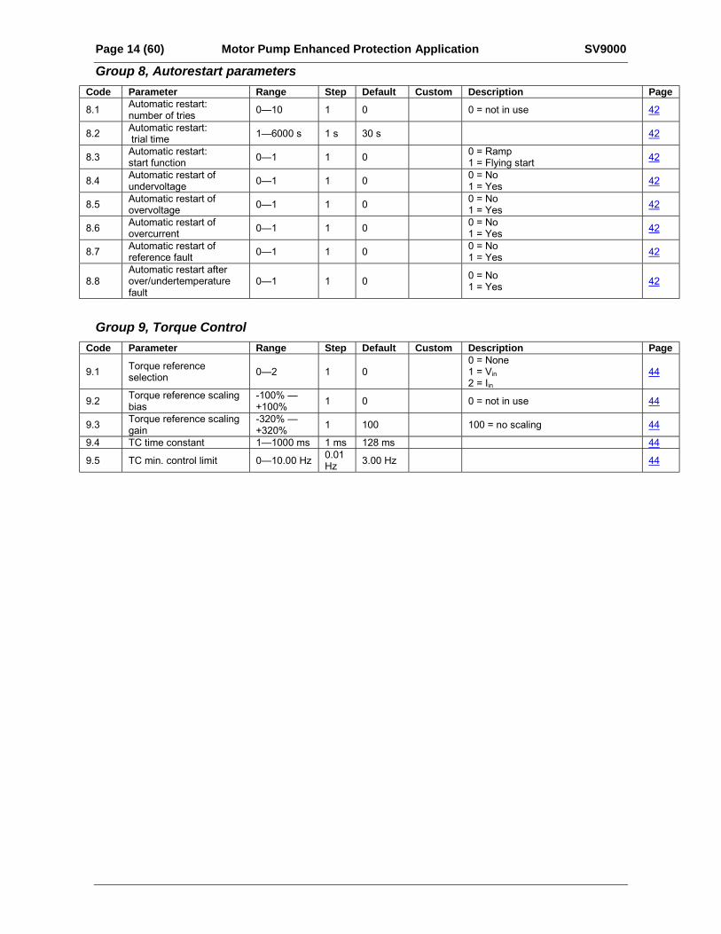
Group 8, Autorestart parametersCode Parameter Range Step Default Custom Description Page8.1 Automatic restart:
number of tries 010 1 0 0 = not in use 42
8.2 Automatic restart: trial time 16000 s 1 s 30 s 42
8.3 Automatic restart:start function 01 1 0 0 = Ramp
1 = Flying start 42
8.4 Automatic restart ofundervoltage 01 1 0 0 = No
1 = Yes 42
8.5 Automatic restart ofovervoltage 01 1 0 0 = No
1 = Yes 42
8.6 Automatic restart ofovercurrent 01 1 0 0 = No
1 = Yes 42
8.7 Automatic restart ofreference fault 01 1 0 0 = No
1 = Yes 42
8.8Automatic restart afterover/undertemperaturefault
01 1 0 0 = No1 = Yes 42
Group 9, Torque ControlCode Parameter Range Step Default Custom Description Page
9.1 Torque referenceselection 02 1 0
0 = None1 = Vin2 = Iin
44
9.2 Torque reference scalingbias
-100% +100% 1 0 0 = not in use 44
9.3 Torque reference scalinggain
-320% +320% 1 100 100 = no scaling 44
9.4 TC time constant 11000 ms 1 ms 128 ms 44
9.5 TC min. control limit 010.00 Hz 0.01Hz 3.00 Hz 44
SV9000 Motor Pump Enhanced Protection Application Page 15 (60)
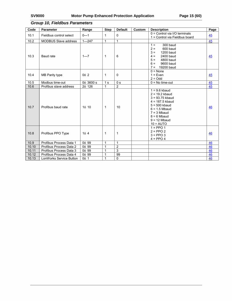
Group 10, Fieldbus ParametersCode Parameter Range Step Default Custom Description Page10.1 Fieldbus control select 01 1 0 0 = Control via I/O terminals
1 = Control via Fieldbus board 45
10.2 MODBUS Slave address 1247 1 1 45
10.3 Baud rate 17 1 6
1 = 300 baud2 = 600 baud3 = 1200 baud4 = 2400 baud5 = 4800 baud6 = 9600 baud7 = 19200 baud
45
10.4 MB Parity type 0ó 2 1 00 = None1 = Even2 = Odd
45
10.5 Modbus time-out 0ó 3600 s 1 s 0 s 0 = No time-out 4510.6 Profibus slave address 2ó 126 1 2 45
10.7 Profibus baud rate 1ó 10 1 10
1 = 9.6 kbaud2 = 19.2 kbaud3 = 93.75 kbaud4 = 187.5 kbaud5 = 500 kbaud6 = 1.5 Mbaud7 = 3 Mbaud8 = 6 Mbaud9 = 12 Mbaud10 = AUTO
46
10.8 Profibus PPO Type 1ó 4 1 1
1 = PPO 12 = PPO 23 = PPO 34 = PPO 4
46
10.9 Profibus Process Data 1 0ó 99 1 1 4610.10 Profibus Process Data 2 0ó 99 1 2 4610.11 Profibus Process Data 3 0ó 99 1 3 4610.12 Profibus Process Data 4 0ó 99 1 99 4610.13 LonWorks Service Button 0ó 1 1 0 46
Page 16 (60) Motor Pump Enhanced Protection Application SV9000
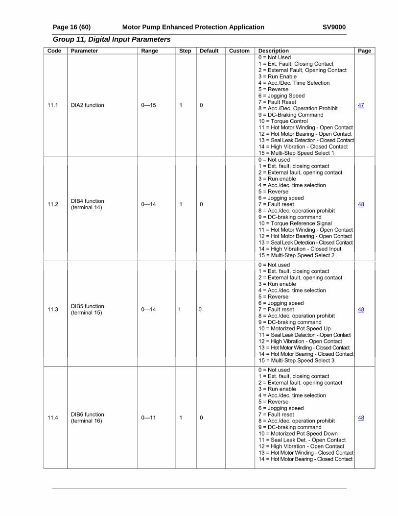
Group 11, Digital Input ParametersCode Parameter Range Step Default Custom Description Page
11.1 DIA2 function 015 1 0
0 = Not Used1 = Ext. Fault, Closing Contact2 = External Fault, Opening Contact3 = Run Enable4 = Acc./Dec. Time Selection5 = Reverse6 = Jogging Speed7 = Fault Reset8 = Acc./Dec. Operation Prohibit9 = DC-Braking Command10 = Torque Control11 = Hot Motor Winding - Open Contact12 = Hot Motor Bearing - Open Contact13 = Seal Leak Detection - Closed Contact14 = High Vibration - Closed Contact15 = Multi-Step Speed Select 1
47
11.2 DIB4 function(terminal 14) 014 1 0
0 = Not used1 = Ext. fault, closing contact2 = External fault, opening contact3 = Run enable4 = Acc./dec. time selection5 = Reverse6 = Jogging speed7 = Fault reset8 = Acc./dec. operation prohibit9 = DC-braking command10 = Torque Reference Signal11 = Hot Motor Winding - Open Contact12 = Hot Motor Bearing - Open Contact13 = Seal Leak Detection - Closed Contact14 = High Vibration - Closed Input
48
15 = Multi-Step Speed Select 2
11.3 DIB5 function(terminal 15) 014 1 0
0 = Not used1 = Ext. fault, closing contact2 = External fault, opening contact3 = Run enable4 = Acc./dec. time selection5 = Reverse6 = Jogging speed7 = Fault reset8 = Acc./dec. operation prohibit9 = DC-braking command10 = Motorized Pot Speed Up11 = Seal Leak Detection - Open Contact12 = High Vibration - Open Contact13 = Hot Motor Winding - Closed Contact14 = Hot Motor Bearing - Closed Contact
48
15 = Multi-Step Speed Select 3
11.4 DIB6 function(terminal 16) 011 1 0
0 = Not used1 = Ext. fault, closing contact2 = External fault, opening contact3 = Run enable4 = Acc./dec. time selection5 = Reverse6 = Jogging speed7 = Fault reset8 = Acc./dec. operation prohibit9 = DC-braking command10 = Motorized Pot Speed Down11 = Seal Leak Det. - Open Contact12 = High Vibration - Open Contact13 = Hot Motor Winding - Closed Contact14 = Hot Motor Bearing - Closed Contact
48
Page 16A (60) Motor Pump Enhanced Protection Application SV9000
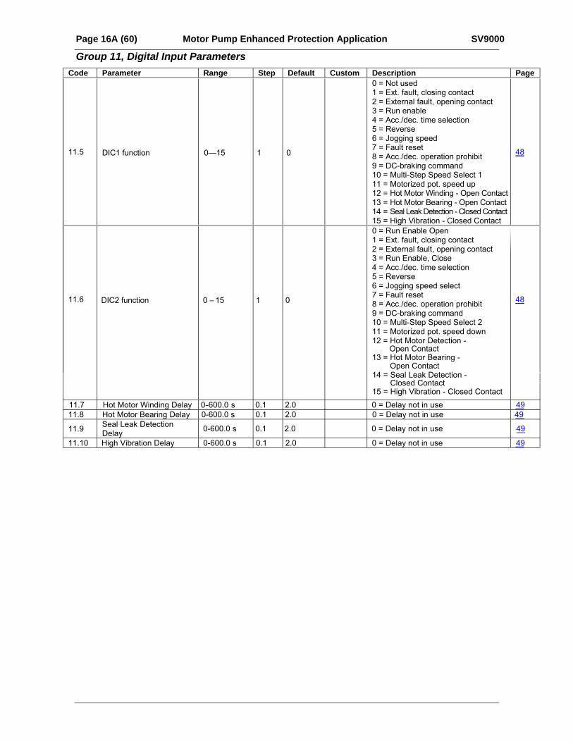
Group 11, Digital Input ParametersCode Parameter Range Step Default Custom Description Page
11.5 DIC1 function 015 1 0
0 = Not used1 = Ext. fault, closing contact2 = External fault, opening contact3 = Run enable4 = Acc./dec. time selection5 = Reverse6 = Jogging speed7 = Fault reset8 = Acc./dec. operation prohibit9 = DC-braking command10 = Multi-Step Speed Select 111 = Motorized pot. speed up12 = Hot Motor Winding - Open Contact13 = Hot Motor Bearing - Open Contact14 = Seal Leak Detection - Closed Contact15 = High Vibration - Closed Contact
48
ss
s
s
11.7 Hot Motor Winding Delay 0-600.0 0.1 2.0 0 = Delay not in use 4911.8 Hot Motor Bearing Delay 0-600.0 0.1 2.0 0 = Delay not in use 49
11.9Seal Leak DetectionDelay
0-600.0 0.1 2.0 0 = Delay not in use 49
11.10 High Vibration Delay 0-600.0 0.1 2.0 0 = Delay not in use 49
11.6 DIC2 function 0 – 15 1 0
0 = Run Enable Open1 = Ext. fault, closing contact2 = External fault, opening contact3 = Run Enable, Close4 = Acc./dec. time selection5 = Reverse6 = Jogging speed select7 = Fault reset8 = Acc./dec. operation prohibit9 = DC-braking command10 = Multi-Step Speed Select 211 = Motorized pot. speed down12 = Hot Motor Detection -
Open Contact13 = Hot Motor Bearing -
Open Contact
14 = Seal Leak Detection - Closed Contact
15 = High Vibration - Closed Contact
48
SV9000 Motor Pump Enhanced Protection Application Page 17 (60)
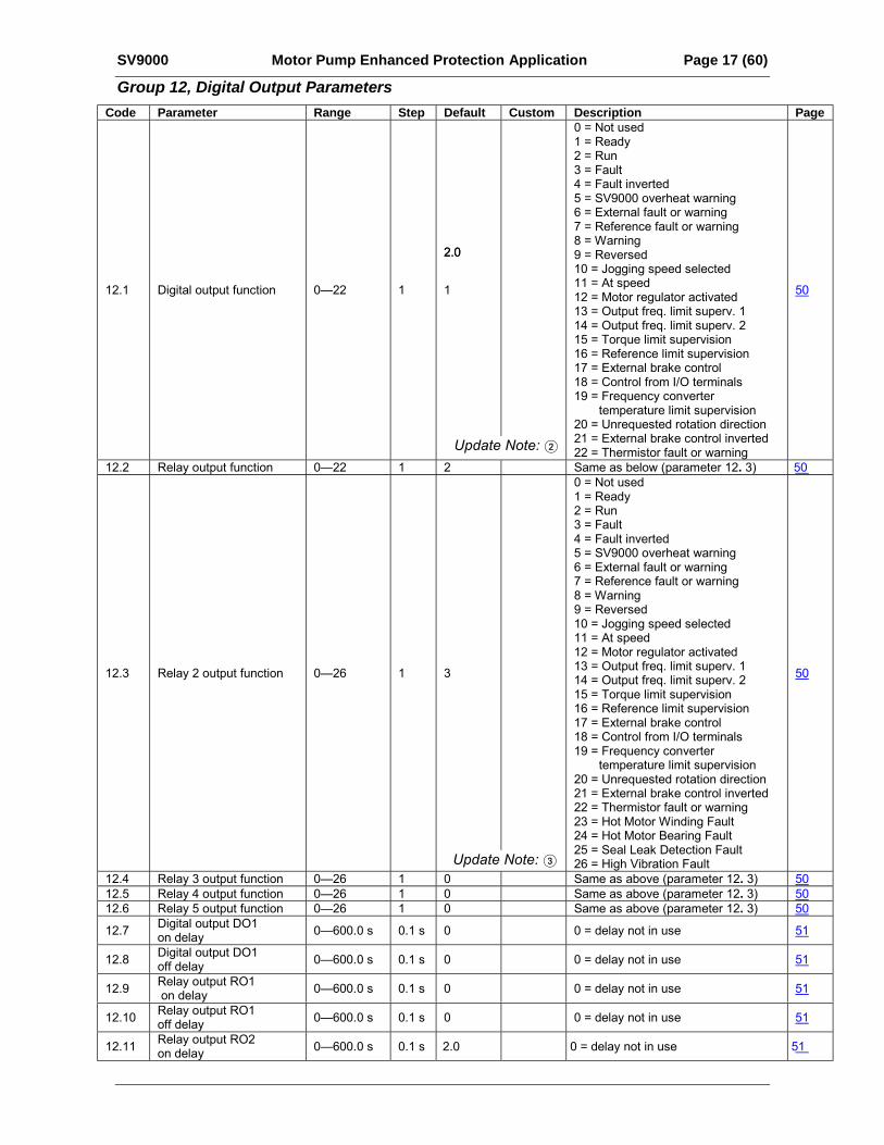
Group 12, Digital Output ParametersCode Parameter Range Step Default Custom Description Page
12.1 Digital output function 022 1 1
0 = Not used1 = Ready2 = Run3 = Fault4 = Fault inverted5 = SV9000 overheat warning6 = External fault or warning7 = Reference fault or warning8 = Warning9 = Reversed10 = Jogging speed selected11 = At speed12 = Motor regulator activated13 = Output freq. limit superv. 114 = Output freq. limit superv. 215 = Torque limit supervision16 = Reference limit supervision17 = External brake control18 = Control from I/O terminals19 = Frequency converter
temperature limit supervision20 = Unrequested rotation direction21 = External brake control inverted22 = Thermistor fault or warning
50
12.2 Relay output function 022 1 2 Same as below (parameter 12. 3) 50
12.3 Relay 2 output function 026 1 3
0 = Not used1 = Ready2 = Run3 = Fault4 = Fault inverted5 = SV9000 overheat warning6 = External fault or warning7 = Reference fault or warning8 = Warning9 = Reversed10 = Jogging speed selected11 = At speed12 = Motor regulator activated13 = Output freq. limit superv. 114 = Output freq. limit superv. 215 = Torque limit supervision16 = Reference limit supervision17 = External brake control18 = Control from I/O terminals19 = Frequency converter
temperature limit supervision20 = Unrequested rotation direction21 = External brake control inverted22 = Thermistor fault or warning23 = Hot Motor Winding Fault24 = Hot Motor Bearing Fault25 = Seal Leak Detection Fault26 = High Vibration Fault
50
12.4 Relay 3 output function 026 1 0 Same as above (parameter 12. 3) 50
Update Note: 2
Update Note: 3
12.5 Relay 4 output function 026 1 0 Same as above (parameter 12. 3) 5012.6 Relay 5 output function 026 1 0 Same as above (parameter 12. 3) 50
12.7 Digital output DO1on delay 0600.0 s 0.1 s 0 0 = delay not in use 51
12.8 Digital output DO1off delay 0600.0 s 0.1 s 0 0 = delay not in use 51
12.9 Relay output RO1 on delay 0600.0 s 0.1 s 0 0 = delay not in use 51
12.10 Relay output RO1off delay 0600.0 s 0.1 s 0 0 = delay not in use 51
12.11 Relay output RO2on delay 0600.0 s 0.1 s 2.0 0 = delay not in use 51
2.02.0
Page 18 (60) Motor Pump Enhanced Protection Application SV9000
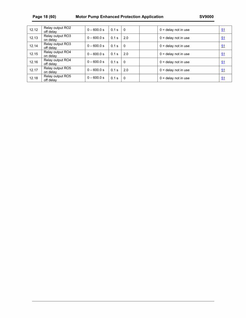
12.12Relay output RO2off delay
0 0 = delay not in use 51
12.13Relay output RO3on delay
2.0 0 = delay not in use 51
12.14Relay output RO3off delay
0 0 = delay not in use 51
12.15Relay output RO4on delay
2.0 0 = delay not in use 51
12.16Relay output RO4off delay
0 0 = delay not in use 51
12.17Relay output RO5on delay
2.0 0 = delay not in use 51
12.18Relay output RO5off delay
0 0 = delay not in use 51
0 – 600.0 s 0.1 s
0.1 s
0.1 s
0.1 s
0.1 s
0.1 s
0.1 s
0 – 600.0 s
0 – 600.0 s
0 – 600.0 s
0 – 600.0 s
0 – 600.0 s
0 – 600.0 s
SV9000 Motor Pump Enhanced Protection Application Page 19 (60)
6.2 Description of Groups 2-10 Parameters
6.2.1 Group 2, Analog Input Signal Parameters2.1 Vin signal range
0 = Signal range 0+10 V
1 = Custom setting range from custom minimum (par. 2.2) to custom maximum (par. 2.3)
2 = Signal range -10+10 V , can be used only with Joystick control
2.2- Vin custom setting minimum2.3 Vin custom setting maximum
With these parameters, Vin can be set for any input signal span within 010 V.
Minimum setting: Set the Vin signal to its minimum level, select parameter 2.2, press theEnter button
Maximum setting:Set the Vin signal to its maximum level, select parameter 2.3, press theEnter button
Note! These parameters can only be set with this procedure (not with arrow up/arrowdown buttons)
2.4 Vin signal inversion0 = no inversion of analog Vin signal.
1 = inversion of analog Vin signal.
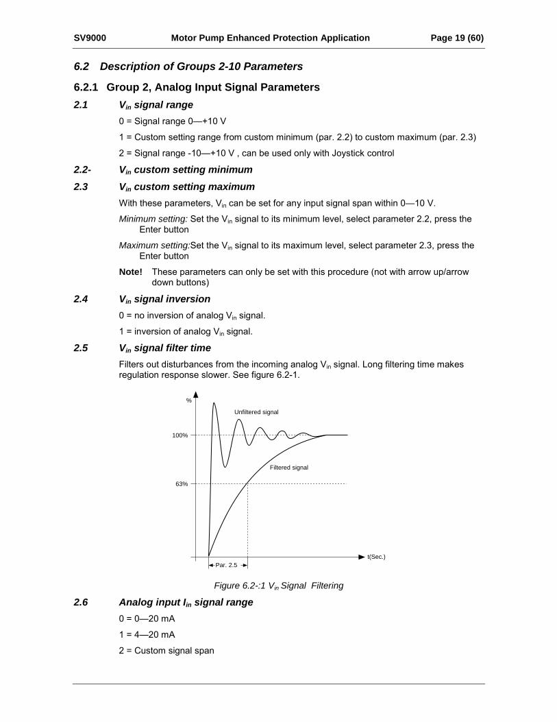
2.5 Vin signal filter timeFilters out disturbances from the incoming analog Vin signal. Long filtering time makesregulation response slower. See figure 6.2-1.
t(Sec.)
Unfiltered signal
%
100%
63%
Filtered signal
Par. 2.5
Figure 6.2-:1 Vin Signal Filtering
2.6 Analog input Iin signal range0 = 020 mA
1 = 420 mA
2 = Custom signal span
Page 20 (60) Motor Pump Enhanced Protection Application SV9000
2.7 Analog input Iin custom setting minimum2.8 Analog input Iin custom setting maximum
With these parameters, the scaling of the input current signal (Iin) range can be setbetween 020 mA.
Minimum setting: Set the Iin signal to its minimum level, select parameter 2.7, press theEnter button.
Maximum setting: Set the Iin signal to its maximum level, select parameter 2.8, press theEnter button.
Note! These parameters can only be set with this procedure (not with arrow up/arrowdown buttons)
2.9 Analog input Iin signal inversion0 = no inversion of Iin input
1 = inversion of Iin input
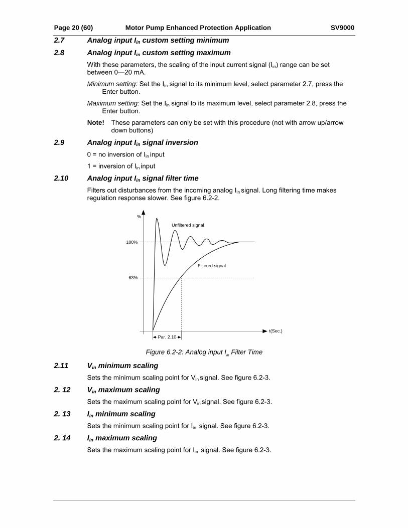
2.10 Analog input Iin signal filter timeFilters out disturbances from the incoming analog Iin signal. Long filtering time makesregulation response slower. See figure 6.2-2.
t(Sec.)
Unfiltered signal
%
100%
63%
Filtered signal
Par. 2.10
Figure 6.2-2: Analog input Iin Filter Time
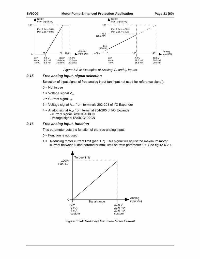
2.11 Vin minimum scalingSets the minimum scaling point for Vin signal. See figure 6.2-3.
2. 12 Vin maximum scalingSets the maximum scaling point for Vin signal. See figure 6.2-3.
2. 13 Iin minimum scalingSets the minimum scaling point for Iin signal. See figure 6.2-3.
2. 14 Iin maximum scalingSets the maximum scaling point for Iin signal. See figure 6.2-3.
SV9000 Motor Pump Enhanced Protection Application Page 21 (60)Scaledinput signal (%)
Par. 2.14 = 30%Par. 2.15 = 80%
100
0
Scaledinput signal (%)
Par. 2.14 = – 30%Par. 2.15 = 140%
100
0Analoginput (%)
Analoginput (%)30 – 3080 100
0 V0 mA4 mA
0 V0 mA4 mA
3.0 V6.0 mA8.8 mA
8.0 V16.0 mA16.8 mA
100 140
8.0 V16.0 mA16.8 mA
10.0 V20.0 mA20.0 mA
10.0 V20.0 mA20.0 mA
76.5(15.3 mA)
17.7(3.5 mA)
Figure 6.2-3: Examples of Scaling Vin and Iin Inputs
2.15 Free analog input, signal selectionSelection of input signal of free analog input (an input not used for reference signal):
0 = Not in use
1 = Voltage signal Vin
2 = Current signal Iin3 = Voltage signal Ain1 from terminals 202-203 of I/O Expander
4 = Analog signal Ain2 from terminal 204-205 of I/O Expander- current signal SV9IOC100CN- voltage signal SV9IOC102CN
2.16 Free analog input, functionThis parameter sets the function of the free analog input:
0 = Function is not used
1 = Reducing motor current limit (par. 1.7). This signal will adjust the maximum motorcurrent between 0 and parameter max. limit set with parameter 1.7. See figure 6.2-4.
Torque limit100%
Par. 1.7
0Analoginput (%)Signal range
10.0 V20.0 mA20.0 mAcustom
0 V0 mA4 mAcustom
Figure 6.2-4: Reducing Maximum Motor Current
Page 22 (60) Motor Pump Enhanced Protection Application SV9000
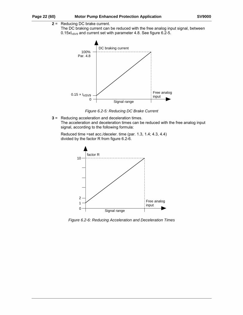
2 = Reducing DC brake current.The DC braking current can be reduced with the free analog input signal, between0.15xInSV9 and current set with parameter 4.8. See figure 6.2-5.
DC braking current100%
Par. 4.8
00.15 × InSV9
Free analoginput
Signal range
Figure 6.2-5: Reducing DC Brake Current
3 = Reducing acceleration and deceleration times.The acceleration and deceleration times can be reduced with the free analog inputsignal, according to the following formula:
Reduced time =set acc./deceler. time (par. 1.3, 1.4; 4.3, 4.4)divided by the factor R from figure 6.2-6.
factor R10
21
0
Free analoginput
Signal range
Figure 6.2-6: Reducing Acceleration and Deceleration Times
SV9000 Motor Pump Enhanced Protection Application Page 23 (60)
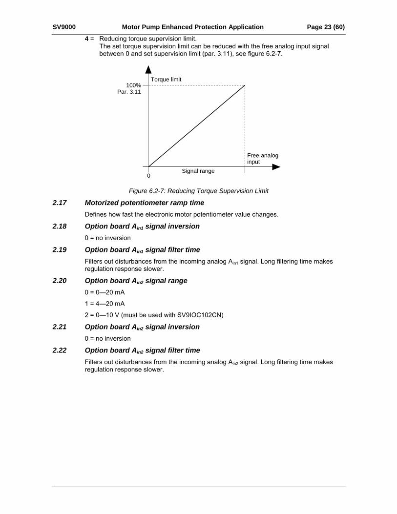
4 = Reducing torque supervision limit.The set torque supervision limit can be reduced with the free analog input signalbetween 0 and set supervision limit (par. 3.11), see figure 6.2-7.
Torque limit100%
Par. 3.11
0
Free analoginput
Signal range
Figure 6.2-7: Reducing Torque Supervision Limit
2.17 Motorized potentiometer ramp timeDefines how fast the electronic motor potentiometer value changes.
2.18 Option board Ain1 signal inversion0 = no inversion
2.19 Option board Ain1 signal filter timeFilters out disturbances from the incoming analog Ain1 signal. Long filtering time makesregulation response slower.
2.20 Option board Ain2 signal range0 = 020 mA
1 = 420 mA
2 = 010 V (must be used with SV9IOC102CN)
2.21 Option board Ain2 signal inversion0 = no inversion
2.22 Option board Ain2 signal filter timeFilters out disturbances from the incoming analog Ain2 signal. Long filtering time makesregulation response slower.
Page 24 (60) Motor Pump Enhanced Protection Application SV9000
6.2.2 Group 3, Analog Output and supervision parameters3.1 Analog output function
See table Group 3, Output and supervision parameters.
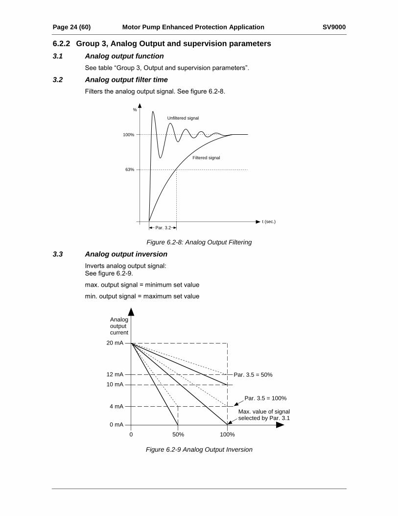
3.2 Analog output filter timeFilters the analog output signal. See figure 6.2-8.
t (sec.)
Unfiltered signal
%
100%
63%
Filtered signal
Par. 3.2
Figure 6.2-8: Analog Output Filtering
3.3 Analog output inversionInverts analog output signal:See figure 6.2-9.
max. output signal = minimum set value
min. output signal = maximum set value
0 50% 100%
20 mA
12 mA
10 mA
4 mA
0 mA
Par. 3.5 = 100%
Par. 3.5 = 50%
Analogoutputcurrent
Max. value of signal selected by Par. 3.1
Figure 6.2-9 Analog Output Inversion
SV9000 Motor Pump Enhanced Protection Application Page 25 (60)
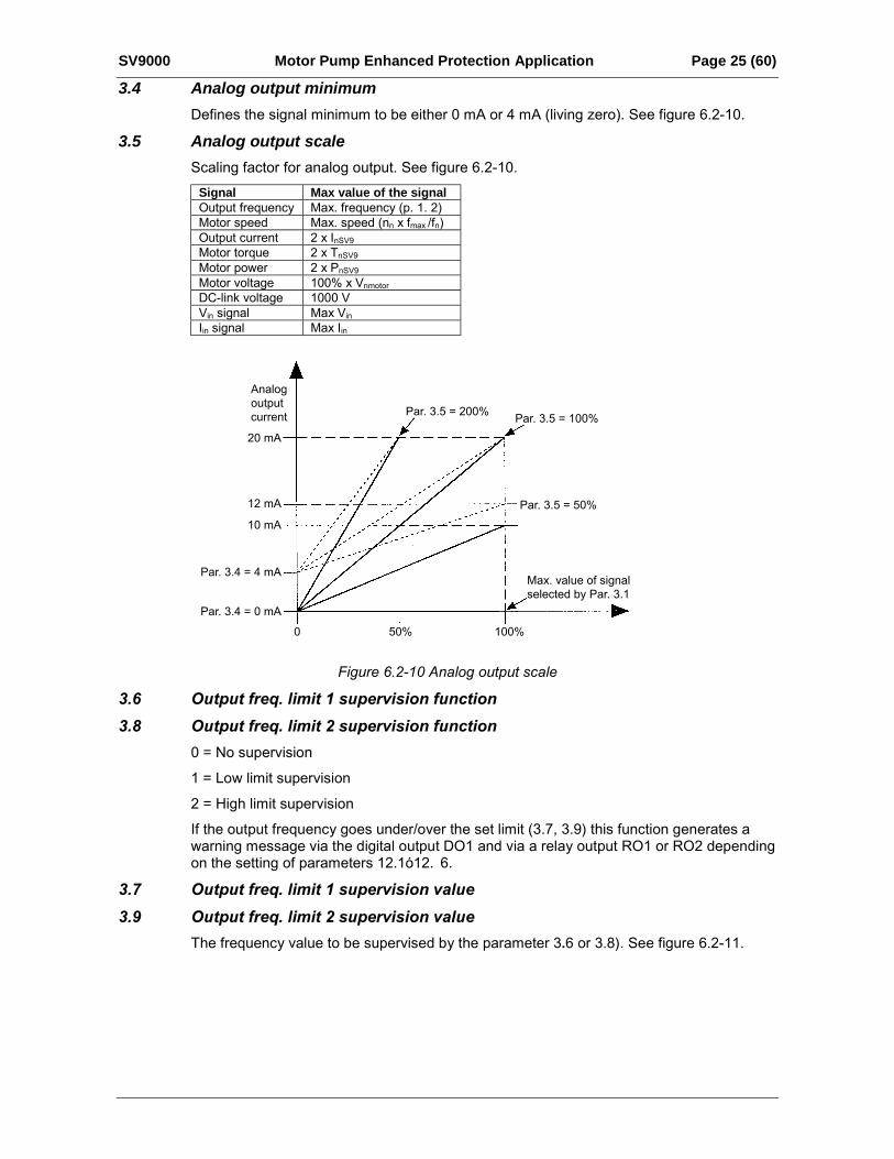
3.4 Analog output minimumDefines the signal minimum to be either 0 mA or 4 mA (living zero). See figure 6.2-10.
3.5 Analog output scaleScaling factor for analog output. See figure 6.2-10.
Signal Max value of the signalOutput frequency Max. frequency (p. 1. 2)Motor speed Max. speed (nn x fmax /fn)Output current 2 x InSV9Motor torque 2 x TnSV9Motor power 2 x PnSV9Motor voltage 100% x VnmotorDC-link voltage 1000 VVin signal Max Vin
3.6 Output freq. limit 1 supervision function
3.8 Output freq. limit 2 supervision function
0 = No supervision
1 = Low limit supervision
2 = High limit supervision
If the output frequency goes under/over the set limit (3.7, 3.9) this function generates awarning message via the digital output DO1 and via a relay output RO1 or RO2 dependingon the setting of parameters 12.1ó12. 6.
3.7 Output freq. limit 1 supervision value
3.9 Output freq. limit 2 supervision value
The frequency value to be supervised by the parameter 3.6 or 3.8). See figure 6.2-11.
Iin signal Max Iin
Figure 6.2-10 Analog output scale
Par. 3.5 = 50%
Par. 3.5 = 100%Par. 3.5 = 200%
Analogoutputcurrent
20 mA
12 mA
10 mA
Par. 3.4 = 4 mA
Par. 3.4 = 0 mA
0 50% 100%
Max. value of signalselected by Par. 3.1

Page 26 (60) Motor Pump Enhanced Protection Application SV9000
f(Hz)
Par. 3.7
21 R0122 R0123 R01
21 R0122 R0123 R01
21 R0122 R0123 R01
t
Figure 6.2-11: Output Frequency Supervision
3.10 Torque limit supervision function0 = No supervision
1 = Low limit supervision
2 = High limit supervision
If the calculated torque value goes under/over the set limit (3.11) this function generates awarning message via the digital output DO1, via a relay output RO1 or RO2 depending onthe setting of parameters 12.112.6.
3.11 Torque limit supervision valueThe calculated torque value to be supervised by parameter 3.10
3.12 Reference limit supervision function0 = No supervision
1 = Low limit supervision
2 = High limit supervision
If the reference value goes under/over the set limit (3.13) this function generates awarning message via the digital output DO1 or via a relay output RO1 or RO2 dependingon the settings of parameters 12.112.6. The supervised reference is the currently activereference. It can be source A or B reference, depending on the DIB6 input, or the panelreference if the panel is the active control source.
3.13 Reference limit supervision valueThe frequency value to be supervised by the parameter 3.12.
3.14 Extern. brake Off-delay3.15 Extern. brake On-delay
With these parameters the timing of external brake can be linked to the Start and Stopcontrol signals, see figure 6.2-12.
The brake control signal can be programmed via the digital output DO1 or via one of relayoutputs RO1 and RO2, see parameters 12.112.6.
SV9000 Motor Pump Enhanced Protection Application Page 27 (60)
3.16 Frequency converter temperature limit supervision function0 = No supervision
1 = Low limit supervision
2 = High limit supervision
If the temperature of the frequency converter goes under/over the set limit (3.17) thisfunction generates a warning message via the digital output DO1 or via the relay outputsRO1 or RO2 depending on the settings of the parameters 12.112.6.
3.17 Frequency converter temperature limit valueThe temperature value to be supervised by the parameter 3.16.
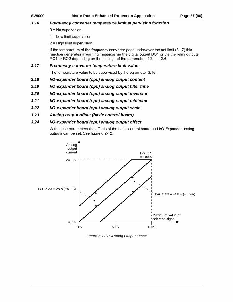
3.18 I/O-expander board (opt.) analog output content3.19 I/O-expander board (opt.) analog output filter time3.20 I/O-expander board (opt.) analog output inversion3.21 I/O-expander board (opt.) analog output minimum3.22 I/O-expander board (opt.) analog output scale3.23 Analog output offset (basic control board)3.24 I/O-expander board (opt.) analog output offset
With these parameters the offsets of the basic control board and I/O-Expander analogoutputs can be set. See figure 6.2-12.
Analogoutput
current
Maximum value ofselected signal
0% 50% 100%
20 mA
0 mA
Par. 3.23 = 25% (+5 mA)
Par. 3.23 = – 30% (– 6 mA)
Par. 3.5 = 100%
Figure 6.2-12: Analog Output Offset

Page 28 (60) Motor Pump Enhanced Protection Application SV9000
6.2.3 Group 4, Drive Control Parameters4.1 Acc./Dec. ramp 1 shape4.2 Acc./Dec. ramp 2 shape
The start and end of the acceleration and deceleration ramps can be smoothed with theseparameters. Setting value 0 gives linear ramp shape, which causes acceleration anddeceleration to act immediately to the changes in the reference signal with the timeconstant set by the parameter 1.3 and 1.4 (4.3 and 4.4).
Setting value 0.110 seconds for parameters 4.1 or 4.2 causes linear acceleration ordeceleration to adopt an S-shape. Parameters 1.3 and 1.4 (4.3 and 4.4) determines thetime constant of acceleration/deceleration in the middle of the curve. See figure 6.2-13.
Hz
0Par. 4.1 (Par. 4.2)
Par. 4.1 (Par. 4.2)
t
Figure 6.2-13: S-Shaped Acceleration/Deceleration
4.3 Acceleration time 24.4 Deceleration time 2
These values correspond to the time required for the output frequency to accelerate fromthe set minimum frequency (par. 1.1) to the set maximum frequency (par. 1.2). Thesetimes give the possibility to set two different acceleration/deceleration time sets for oneapplication. The active set can be selected with the programmable digital input of thisapplication, see parameter group 11.
Acceleration/deceleration times can be reduced with an external free analog input signal,see parameters 2.13 and 2.14.
4.5 Brake chopper0 = No brake chopper
1 = Brake chopper and brake resistor installed
2 = External brake chopper
When the frequency converter is decelerating the motor, the inertia of the motor and theload are fed into the external brake resistor. This enables the frequency converter todecelerate the load with the torque equal to that of acceleration, if the brake resistor isselected correctly. See separate Brake resistor installation manual.
SV9000 Motor Pump Enhanced Protection Application Page 29 (60)
4.6 Start functionRamp:
0 The frequency converter starts from 0 Hz and accelerates to the set referencefrequency within the set acceleration time. (Load inertia or starting friction may causeprolonged acceleration times).
Flying start:
1 The frequency converter is able to start into running motor by applying a small torqueto motor and searching for frequency corresponding to the speed the motor isrunning at. Searching starts from the maximum frequency towards the actualfrequency until the correct value is detected. Thereafter the output frequency will beaccelerated/decelerated to the set reference value according to the setacceleration/deceleration parameters.
Use this mode if the motor is coasting when the start command is given. With theflying start it is possible to ride through short utility voltage interruptions.
4.7 Stop functionCoasting:
0 The motor coasts to a halt without any control from the frequency converter, after theStop command.
Ramp:
1 After the Stop command, the speed of the motor is decelerated according to the setdeceleration parameters. If the regenerated energy is high it may be necessary touse an external braking resistor for faster deceleration.
4.8 DC-braking currentDefines the current injected into the motor during the DC braking.
The DC braking current can be reduced from the setpoint with an external free analogsignal, see parameters 2.15 and 2.16.
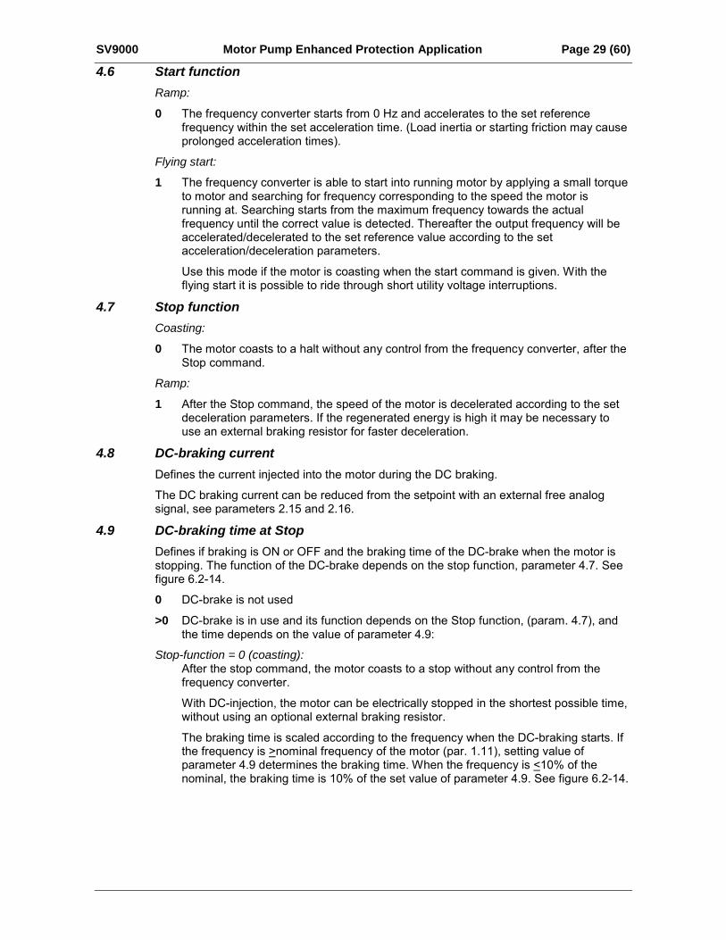
4.9 DC-braking time at StopDefines if braking is ON or OFF and the braking time of the DC-brake when the motor isstopping. The function of the DC-brake depends on the stop function, parameter 4.7. Seefigure 6.2-14.
0 DC-brake is not used
>0 DC-brake is in use and its function depends on the Stop function, (param. 4.7), andthe time depends on the value of parameter 4.9:
Stop-function = 0 (coasting):After the stop command, the motor coasts to a stop without any control from thefrequency converter.
With DC-injection, the motor can be electrically stopped in the shortest possible time,without using an optional external braking resistor.
The braking time is scaled according to the frequency when the DC-braking starts. Ifthe frequency is >nominal frequency of the motor (par. 1.11), setting value ofparameter 4.9 determines the braking time. When the frequency is <10% of thenominal, the braking time is 10% of the set value of parameter 4.9. See figure 6.2-14.
Page 30 (60) Motor Pump Enhanced Protection Application SV9000
fn
RunStop
t = 1 × Par. 4.9
tDC braking On
Motor speed
Output frequencyfn
RunStop
Motor speed
Output frequency
DC braking On
t
t = 0.1 × Par. 4.9
fout (Hz) fout (Hz)
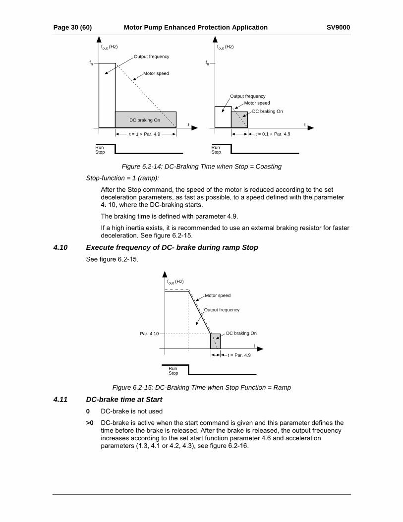
Figure 6.2-14: DC-Braking Time when Stop = Coasting
Stop-function = 1 (ramp):
After the Stop command, the speed of the motor is reduced according to the setdeceleration parameters, as fast as possible, to a speed defined with the parameter4. 10, where the DC-braking starts.
The braking time is defined with parameter 4.9.
If a high inertia exists, it is recommended to use an external braking resistor for fasterdeceleration. See figure 6.2-15.
4.10 Execute frequency of DC- brake during ramp StopSee figure 6.2-15.
RunStop
Par. 4.10
Motor speed
Output frequency
DC braking On
t = Par. 4.9
t
fout (Hz)
Figure 6.2-15: DC-Braking Time when Stop Function = Ramp
4.11 DC-brake time at Start0 DC-brake is not used
>0 DC-brake is active when the start command is given and this parameter defines thetime before the brake is released. After the brake is released, the output frequencyincreases according to the set start function parameter 4.6 and accelerationparameters (1.3, 4.1 or 4.2, 4.3), see figure 6.2-16.
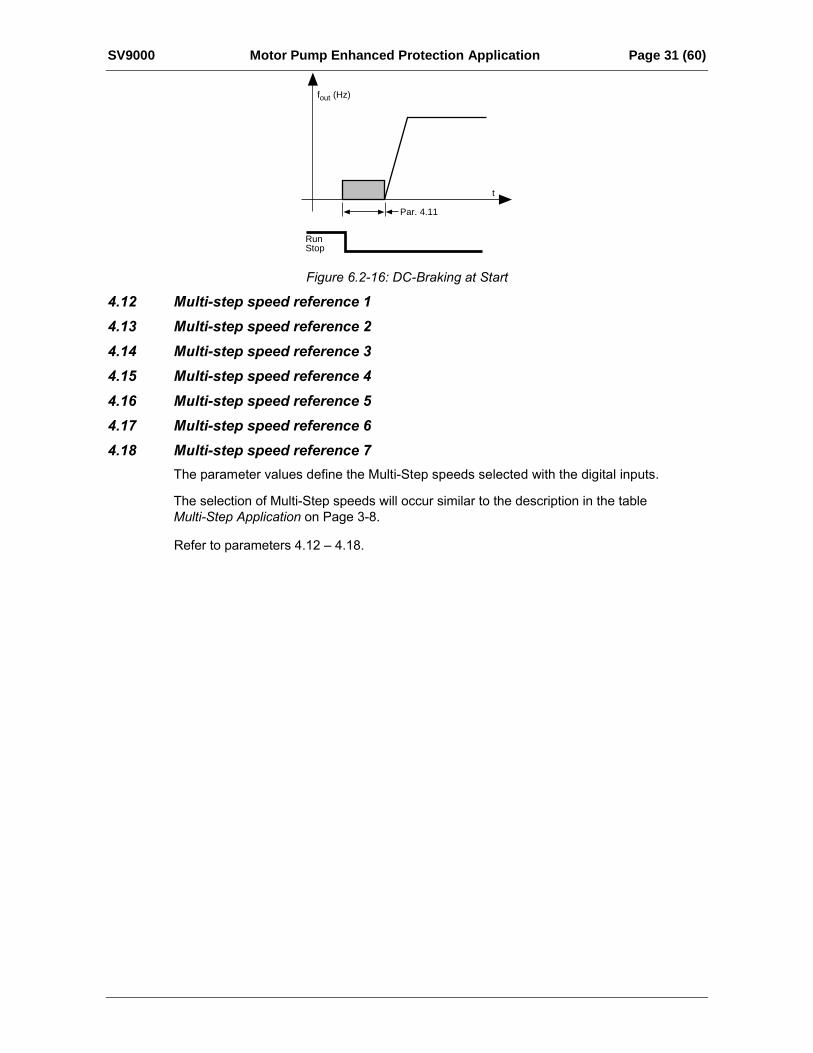
SV9000 Motor Pump Enhanced Protection Application Page 31 (60)
RunStop
fout (Hz)
t
Par. 4.11
Figure 6.2-16: DC-Braking at Start
4.12 Multi-step speed reference 1
4.13 Multi-step speed reference 2
4.14 Multi-step speed reference 3
4.15 Multi-step speed reference 4
4.16 Multi-step speed reference 5
4.17 Multi-step speed reference 6
4.18 Multi-step speed reference 7
The parameter values define the Multi-Step speeds selected with the digital inputs.
The selection of Multi-Step speeds will occur similar to the description in the tableMulti-Step Application on Page 3-8.
Refer to parameters 4.12 – 4.18.
Page 32 (60) Motor Pump Enhanced Protection Application SV9000
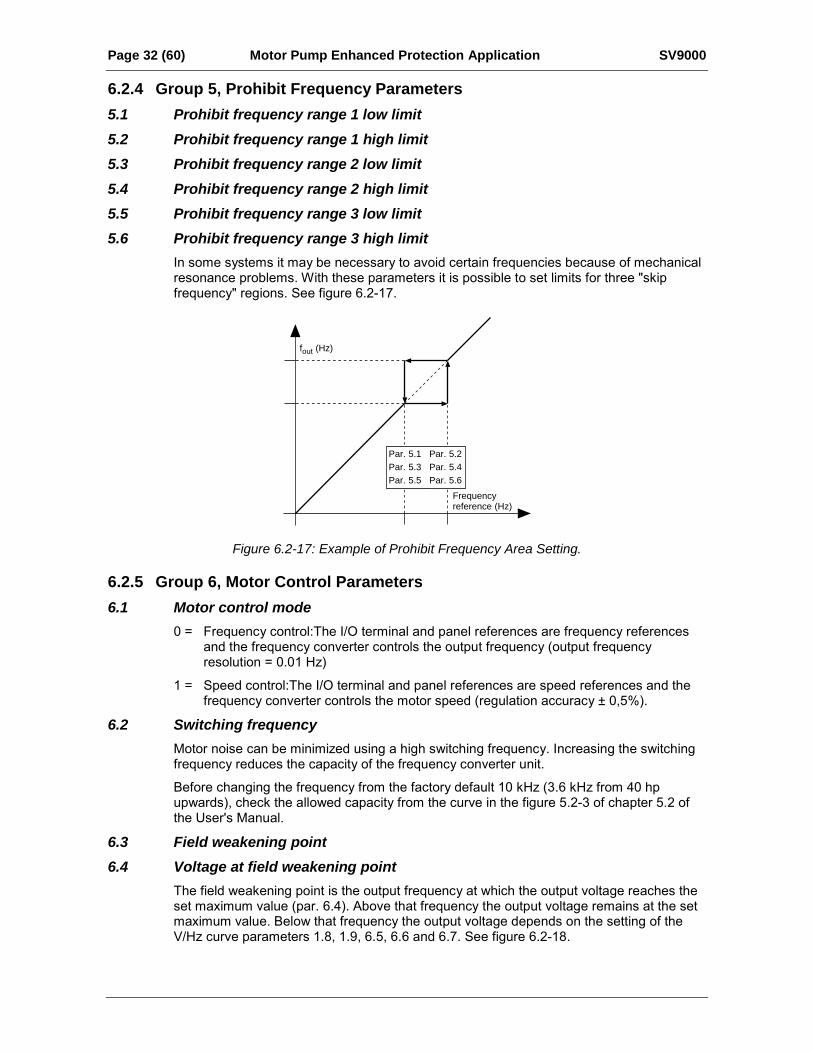
6.2.4 Group 5, Prohibit Frequency Parameters5.1 Prohibit frequency range 1 low limit5.2 Prohibit frequency range 1 high limit5.3 Prohibit frequency range 2 low limit5.4 Prohibit frequency range 2 high limit5.5 Prohibit frequency range 3 low limit5.6 Prohibit frequency range 3 high limit
In some systems it may be necessary to avoid certain frequencies because of mechanicalresonance problems. With these parameters it is possible to set limits for three "skipfrequency" regions. See figure 6.2-17.
fout (Hz)
Frequencyreference (Hz)
Par. 5.1 Par. 5.2Par. 5.3 Par. 5.4Par. 5.5 Par. 5.6
Figure 6.2-17: Example of Prohibit Frequency Area Setting.
6.2.5 Group 6, Motor Control Parameters6.1 Motor control mode
0 = Frequency control:The I/O terminal and panel references are frequency referencesand the frequency converter controls the output frequency (output frequencyresolution = 0.01 Hz)
1 = Speed control:The I/O terminal and panel references are speed references and thefrequency converter controls the motor speed (regulation accuracy ± 0,5%).
6.2 Switching frequencyMotor noise can be minimized using a high switching frequency. Increasing the switchingfrequency reduces the capacity of the frequency converter unit.
Before changing the frequency from the factory default 10 kHz (3.6 kHz from 40 hpupwards), check the allowed capacity from the curve in the figure 5.2-3 of chapter 5.2 ofthe User's Manual.
6.3 Field weakening point6.4 Voltage at field weakening point
The field weakening point is the output frequency at which the output voltage reaches theset maximum value (par. 6.4). Above that frequency the output voltage remains at the setmaximum value. Below that frequency the output voltage depends on the setting of theV/Hz curve parameters 1.8, 1.9, 6.5, 6.6 and 6.7. See figure 6.2-18.
SV9000 Motor Pump Enhanced Protection Application Page 33 (60)
When the parameters 1.10 and 1.11, nominal voltage and nominal frequency of the motor,are set, parameters 6.3 and 6.4 are set automatically to the corresponding values. Ifdifferent values for the field weakening point and the maximum output voltage arerequired, change these parameters after setting the parameters 1.10 and 1.11.
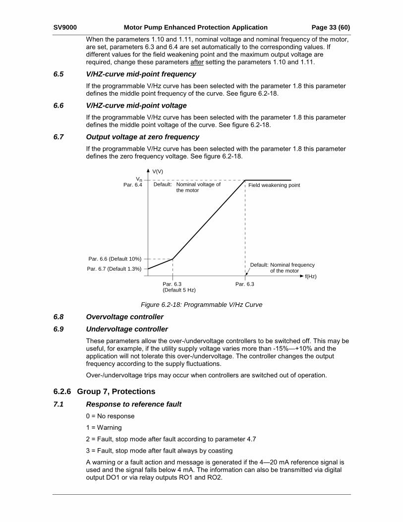
6.5 V/HZ-curve mid-point frequencyIf the programmable V/Hz curve has been selected with the parameter 1.8 this parameterdefines the middle point frequency of the curve. See figure 6.2-18.
6.6 V/HZ-curve mid-point voltageIf the programmable V/Hz curve has been selected with the parameter 1.8 this parameterdefines the middle point voltage of the curve. See figure 6.2-18.
6.7 Output voltage at zero frequencyIf the programmable V/Hz curve has been selected with the parameter 1.8 this parameterdefines the zero frequency voltage. See figure 6.2-18.
VnPar. 6.4
V(V)
f(Hz)
Default: Nominal voltage ofthe motor
Default: Nominal frequencyof the motor
Field weakening point
Par. 6.3Par. 6.3(Default 5 Hz)
Par. 6.7 (Default 1.3%)
Par. 6.6 (Default 10%)
Figure 6.2-18: Programmable V/Hz Curve
6.8 Overvoltage controller6.9 Undervoltage controller
These parameters allow the over-/undervoltage controllers to be switched off. This may beuseful, for example, if the utility supply voltage varies more than -15%+10% and theapplication will not tolerate this over-/undervoltage. The controller changes the outputfrequency according to the supply fluctuations.
Over-/undervoltage trips may occur when controllers are switched out of operation.
6.2.6 Group 7, Protections7.1 Response to reference fault
0 = No response
1 = Warning
2 = Fault, stop mode after fault according to parameter 4.7
3 = Fault, stop mode after fault always by coasting
A warning or a fault action and message is generated if the 420 mA reference signal isused and the signal falls below 4 mA. The information can also be transmitted via digitaloutput DO1 or via relay outputs RO1 and RO2.
Page 34 (60) Motor Pump Enhanced Protection Application SV9000
7.2 Response to external fault0 = No response
1 = Warning
2 = Fault, stop mode after fault according to parameter 4.7
3 = Fault, stop mode after fault always by coasting
A warning or a fault action and message is caused by the external fault signal in the digitalinput DIA3. The information can also be transmitted via digital output DO1 or via relayoutputs RO1 and RO2.
7.3 Phase supervision of the motor0 = No action
2 = Fault
Phase supervision of the motor ensures that the motor phases have approximately equalcurrent.
7.4 Earth fault protection0 = No action
2 = Fault
Ground fault protection ensures that the sum of the motor phase currents is zero. Theprotection is always active and protects the frequency converter from ground faults withhigh currents.
SV9000 Motor Pump Enhanced Protection Application Page 35 (60)
7.5-7.9 GeneralThe motor thermal protection is to protect the motor from overheating. The SV9000 driveis capable of supplying higher than nominal current to the motor. If the load requires thishigh current there is a risk that motor will be thermally overloaded. This is true especiallyat low frequencies. At low frequencies the cooling effect of the motor is reduced, reducingthe capacity of the motor. If the motor is equipped with an external fan the capacityreduction at low speeds is small.
The motor thermal protection is based on a calculated model and it uses the outputcurrent of the drive to determine the load on the motor. When the power of the drive isturned on, the model uses the heatsink temperature to determine the initial thermal stateof the motor. The calculated model assumes that the ambient temperature of the motor is40°C.
The motor thermal protection can be adjusted by setting the following parameters. Thethermal current IT specifies the load current above which the motor is overloaded. Thisthermal current limit is a function of the output frequency. The curve for IT is set withparameters 7.6, 7.7 and 7.9, see figure 6.2-19. The parameter default values are takenfrom the motor name plate data.
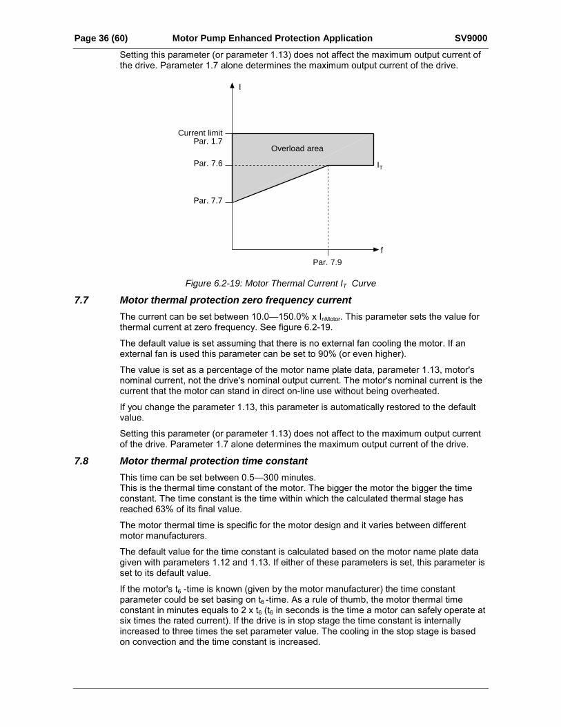
With the output current at IT the thermal state will reach the nominal value (100%). Thethermal state changes proportionally to the square of the current. With output current at75% of IT the thermal state will reach 56% value and with output current at 120% of IT thethermal state would reach 144% value. The function will trip the drive (see par. 7.5) if thethermal state reaches a value of 105%. The speed of change in the thermal state isdetermined by the time constant parameter 7.8. The bigger the motor the longer it takes toreach the final temperature.
The thermal state of the motor can be monitored through the display. See the table formonitoring items. (User's Manual, table 7.3-1).
CAUTION! The calculated model does not protect the motor if the airflow to the motor isreduced by blocked air intake grill.
7.5 Motor thermal protectionOperation:0 = Not in use
1 = Warning
2 = Trip function
Tripping and warning will display the same message code. If tripping is selected the drivewill stop and activate the fault stage.
Deactivating the protection, setting the parameter to 0, will reset the thermal stage of themotor to 0%.
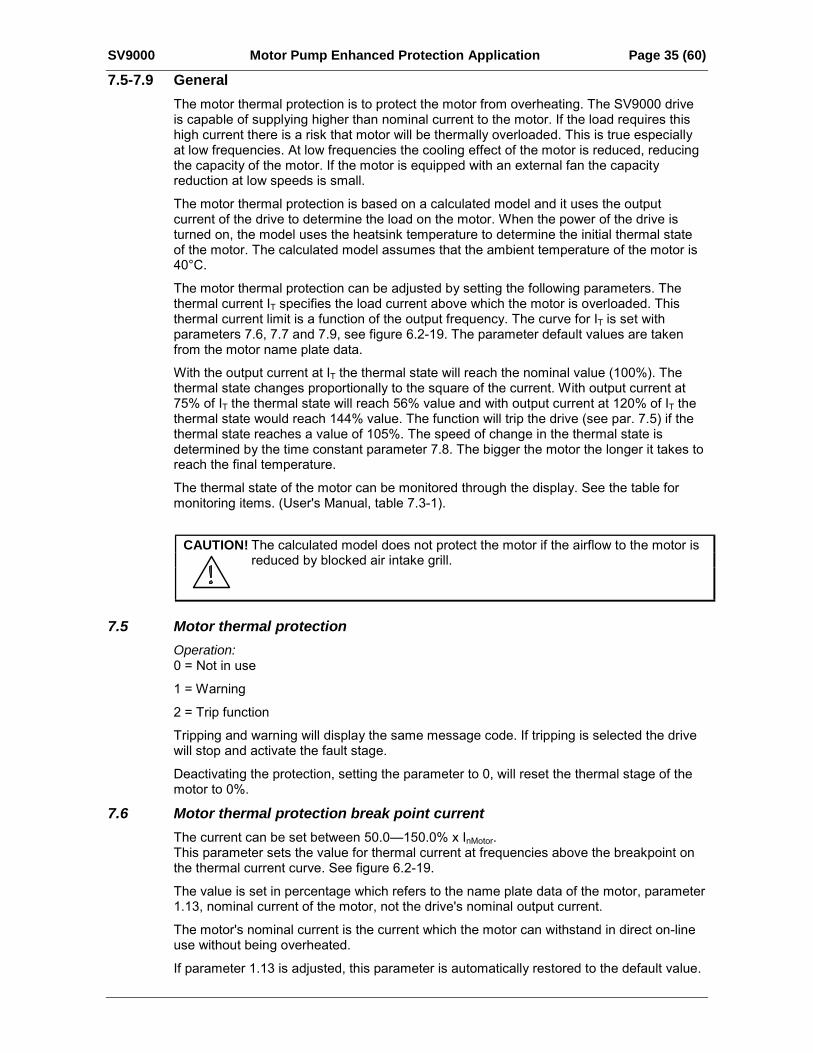
7.6 Motor thermal protection break point currentThe current can be set between 50.0150.0% x InMotor.This parameter sets the value for thermal current at frequencies above the breakpoint onthe thermal current curve. See figure 6.2-19.
The value is set in percentage which refers to the name plate data of the motor, parameter1.13, nominal current of the motor, not the drive's nominal output current.
The motor's nominal current is the current which the motor can withstand in direct on-lineuse without being overheated.
If parameter 1.13 is adjusted, this parameter is automatically restored to the default value.
Page 36 (60) Motor Pump Enhanced Protection Application SV9000
Setting this parameter (or parameter 1.13) does not affect the maximum output current ofthe drive. Parameter 1.7 alone determines the maximum output current of the drive.
I
f
IT
Par. 7.9
Current limitPar. 1.7
Par. 7.6
Par. 7.7
Overload area
Figure 6.2-19: Motor Thermal Current IT Curve
7.7 Motor thermal protection zero frequency currentThe current can be set between 10.0150.0% x InMotor. This parameter sets the value forthermal current at zero frequency. See figure 6.2-19.
The default value is set assuming that there is no external fan cooling the motor. If anexternal fan is used this parameter can be set to 90% (or even higher).
The value is set as a percentage of the motor name plate data, parameter 1.13, motor'snominal current, not the drive's nominal output current. The motor's nominal current is thecurrent that the motor can stand in direct on-line use without being overheated.
If you change the parameter 1.13, this parameter is automatically restored to the defaultvalue.
Setting this parameter (or parameter 1.13) does not affect to the maximum output currentof the drive. Parameter 1.7 alone determines the maximum output current of the drive.
7.8 Motor thermal protection time constantThis time can be set between 0.5300 minutes.This is the thermal time constant of the motor. The bigger the motor the bigger the timeconstant. The time constant is the time within which the calculated thermal stage hasreached 63% of its final value.
The motor thermal time is specific for the motor design and it varies between differentmotor manufacturers.
The default value for the time constant is calculated based on the motor name plate datagiven with parameters 1.12 and 1.13. If either of these parameters is set, this parameter isset to its default value.
If the motor's t6 -time is known (given by the motor manufacturer) the time constantparameter could be set basing on t6 -time. As a rule of thumb, the motor thermal timeconstant in minutes equals to 2 x t6 (t6 in seconds is the time a motor can safely operate atsix times the rated current). If the drive is in stop stage the time constant is internallyincreased to three times the set parameter value. The cooling in the stop stage is basedon convection and the time constant is increased.
SV9000 Motor Pump Enhanced Protection Application Page 37 (60)
7.9 Motor thermal protection break point frequencyThe frequency can be set between 10500 Hz.
This is the breakpoint of thermal current curve. With frequencies above this point thethermal capacity of the motor is assumed to be constant. See figure 6.2-20.
The default value is based on the motor's name plate data, parameter 1.11. It is 35 Hz fora 50 Hz motor and 42 Hz for a 60 Hz motor. More generally it is 70% of the frequency atfield weakening point (parameter 6.3). Changing either parameter 1.11 or 6.3 will restorethis parameter to its default value.
Trip/WarningPar. 7.5
Time constant T ➊
➊ Changed with motor size and adjusted with Par. 7.8
Time
Motor temperature
105%
Motorcurrent
IIT
Motor temperature Ø = ( )2 × (1 – e )IIT
– t T
Figure 6.2-20: Calculating Motor Temperature
Page 38 (60) Motor Pump Enhanced Protection Application SV9000
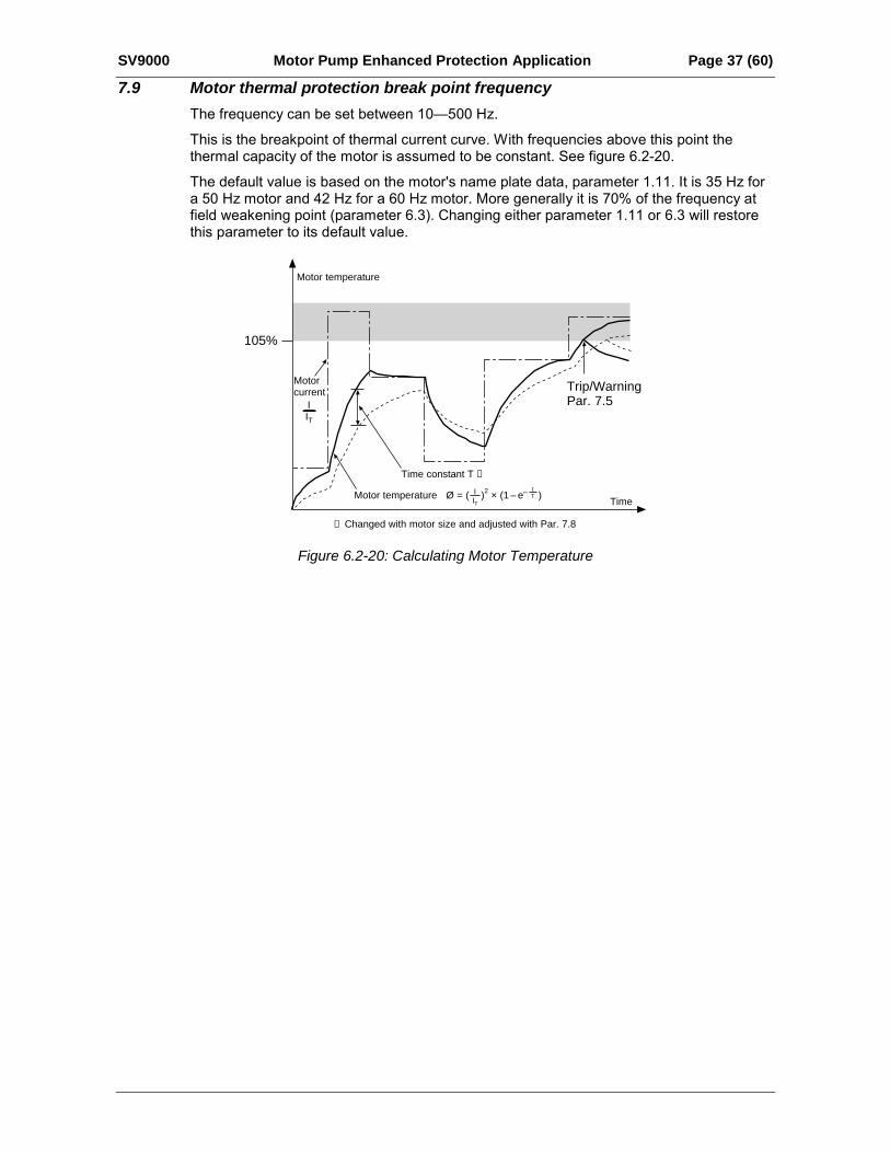
Parameters 7. 10— 7. 13, Stall protectionGeneralMotor stall protection protects the motor from short time overload situations like a stalledshaft. The reaction time of stall protection can be set shorter than with motor thermalprotection. The stall state is defined with two parameters: 7.11 Stall Current, and 7.13 StallFrequency. If the current is higher than the set limit and output frequency is lower than theset limit, the stall state is true. There is actually no real indication of the shaft rotation. Stallprotection is a type of overcurrent protection.
7.10 Stall protectionOperation:
0 = Not in use
1 = Warning
2 = Trip function
Tripping and warning will display the same message code. If tripping is set on, the drivewill stop and activate the fault stage. Setting the parameter to 0 will deactivate theprotection and will reset the stall time counter to zero.
I
f
Par. 7.13
Stall area
Par. 7.11
Figure 6.2-21: Setting the Stall Characteristics
7.11 Stall current limitThe current can be set to 0.0200% x InMotor.
In a stall state the current is above this limit. See figure 6.2-21. The value is set as apercentage of the motor's name plate data, parameter 1.13, motor's nominal current. Ifparameter 1.13 is adjusted, this parameter is automatically restored to the default value.
SV9000 Motor Pump Enhanced Protection Application Page 39 (60)
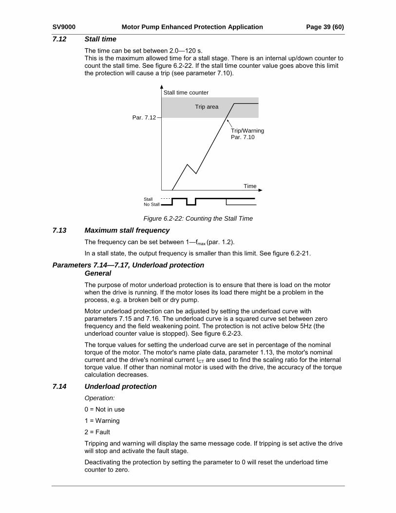
7.12 Stall timeThe time can be set between 2.0120 s.This is the maximum allowed time for a stall stage. There is an internal up/down counter tocount the stall time. See figure 6.2-22. If the stall time counter value goes above this limitthe protection will cause a trip (see parameter 7.10).
Stall time counter
Time
StallNo Stall
Trip/WarningPar. 7.10
Trip area
Par. 7.12
Figure 6.2-22: Counting the Stall Time
7.13 Maximum stall frequencyThe frequency can be set between 1fmax (par. 1.2).
In a stall state, the output frequency is smaller than this limit. See figure 6.2-21.
Parameters 7.14—7.17, Underload protectionGeneralThe purpose of motor underload protection is to ensure that there is load on the motorwhen the drive is running. If the motor loses its load there might be a problem in theprocess, e.g. a broken belt or dry pump.
Motor underload protection can be adjusted by setting the underload curve withparameters 7.15 and 7.16. The underload curve is a squared curve set between zerofrequency and the field weakening point. The protection is not active below 5Hz (theunderload counter value is stopped). See figure 6.2-23.
The torque values for setting the underload curve are set in percentage of the nominaltorque of the motor. The motor's name plate data, parameter 1.13, the motor's nominalcurrent and the drive's nominal current ICT are used to find the scaling ratio for the internaltorque value. If other than nominal motor is used with the drive, the accuracy of the torquecalculation decreases.
7.14 Underload protectionOperation:
0 = Not in use
1 = Warning
2 = Fault
Tripping and warning will display the same message code. If tripping is set active the drivewill stop and activate the fault stage.
Deactivating the protection by setting the parameter to 0 will reset the underload timecounter to zero.
Page 40 (60) Motor Pump Enhanced Protection Application SV9000
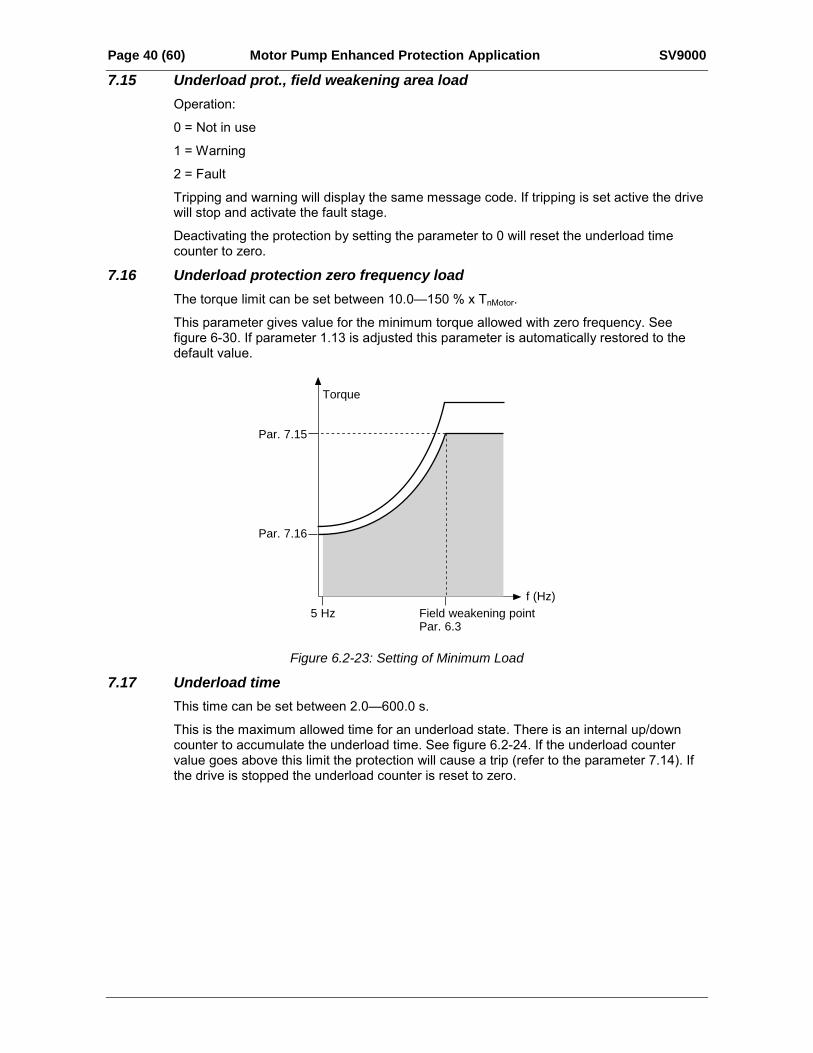
7.15 Underload prot., field weakening area loadOperation:
0 = Not in use
1 = Warning
2 = Fault
Tripping and warning will display the same message code. If tripping is set active the drivewill stop and activate the fault stage.
Deactivating the protection by setting the parameter to 0 will reset the underload timecounter to zero.
7.16 Underload protection zero frequency loadThe torque limit can be set between 10.0150 % x TnMotor.
This parameter gives value for the minimum torque allowed with zero frequency. Seefigure 6-30. If parameter 1.13 is adjusted this parameter is automatically restored to thedefault value.
Torque
5 Hz Field weakening pointPar. 6.3
f (Hz)
Underload area
Par. 7.15
Par. 7.16
Figure 6.2-23: Setting of Minimum Load
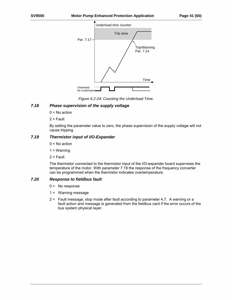
7.17 Underload timeThis time can be set between 2.0600.0 s.
This is the maximum allowed time for an underload state. There is an internal up/downcounter to accumulate the underload time. See figure 6.2-24. If the underload countervalue goes above this limit the protection will cause a trip (refer to the parameter 7.14). Ifthe drive is stopped the underload counter is reset to zero.
SV9000 Motor Pump Enhanced Protection Application Page 41 (60)
Underload time counter
Time
UnderloadNo Underload
Trip/WarningPar. 7.14
Trip area
Par. 7.17
Figure 6.2-24: Counting the Underload Time.
7.18 Phase supervision of the supply voltage0 = No action
2 = Fault
By setting the parameter value to zero, the phase supervision of the supply voltage will notcause tripping
7.19 Thermistor input of I/O-Expander0 = No action
1 = Warning
2 = Fault
The thermistor connected to the thermistor input of the I/O-expander board supervises thetemperature of the motor. With parameter 7.19 the response of the frequency convertercan be programmed when the thermistor indicates overtemperature.
7.20 Response to fieldbus fault0 = No response
1 = Warning message
2 = Fault message, stop mode after fault according to parameter 4.7. A warning or afault action and message is generated from the fieldbus card if the error occurs of thebus system physical layer.
Page 42 (60) Motor Pump Enhanced Protection Application SV9000
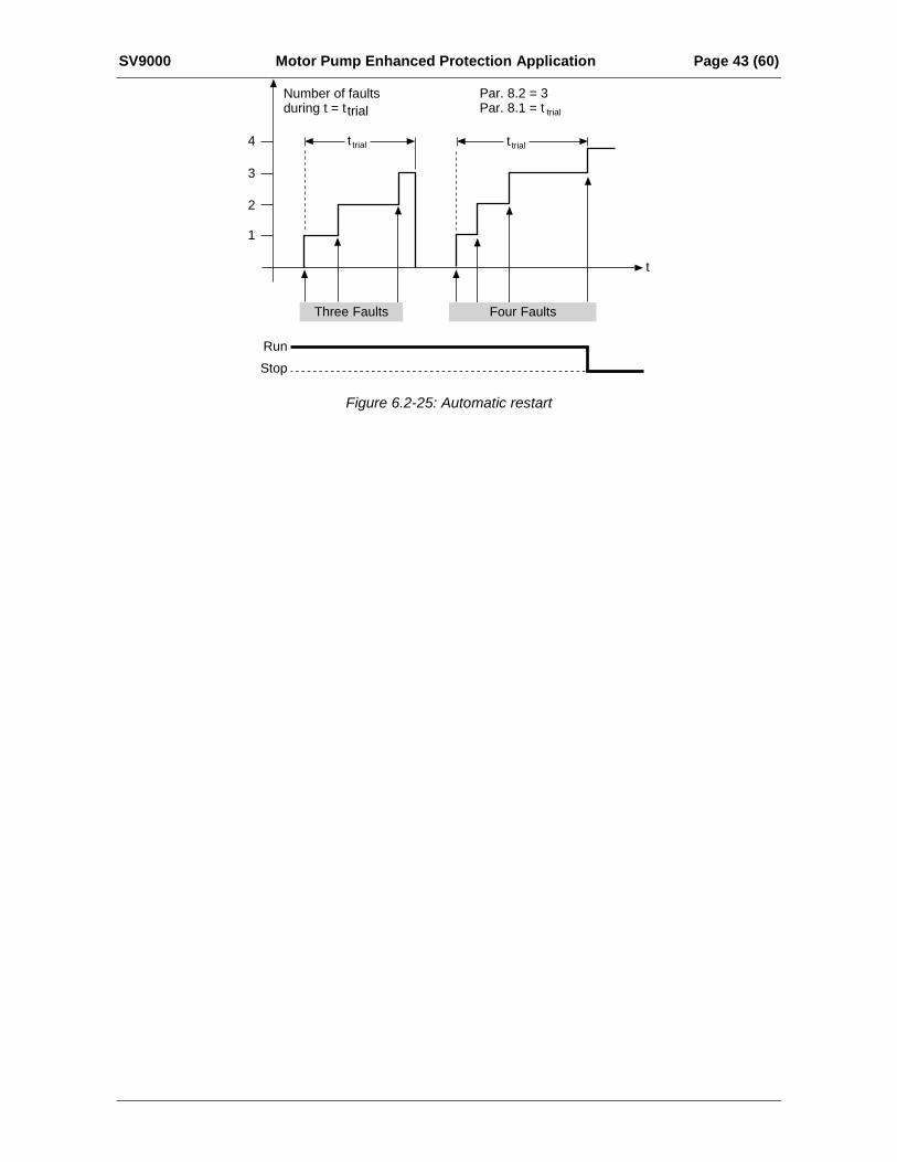
6.2.7 Group 8, Autorestart Parameters8.1 Automatic restart: number of tries8.2 Automatic restart: trial time
The Automatic restart function restarts the frequency converter after the faults selectedwith parameters 8.48.8. The Start function for Automatic restart is selected withparameter 8.3.
Parameter 8.1 determines how many automatic restarts can be made during the trial timeset by the parameter 8.2.
The time counting starts from the first auto-restart. If the number of restarts does notexceed the value of the parameter 8.1 during the trial time, the counting is cleared afterthe time is elapsed and next fault starts the counting again.
8.3 Automatic restart: start functionThe parameter defines the start mode:
0 = Start with ramp
1 = Flying start, see parameter 4.6.
8.4 Automatic restart of undervoltage0 = No automatic restart after undervoltage fault trip
1 = Automatic restart after undervoltage fault condition returns to normal condition (DC-link voltage returns to the normal level)
8.5 Automatic restart of overvoltage0 = No automatic restart after overvoltage fault trip
1 = Automatic restart after overvoltage fault condition returns to the normal condition(DC-link voltage returns to the normal level)
8.6 Automatic restart of overcurrent0 = No automatic restart after overcurrent fault trip
1 = Automatic restart after overcurrent faults
8.7 Automatic restart of reference fault0 = No automatic restart after reference fault trip
1 = Automatic restart after analog current reference signal (420 mA) returns to thenormal level (>4 mA)
8.8 Automatic restart after over/undertemperature fault0 = No automatic restart after temperature fault trip
1 = Automatic restart after heatsink temperature has returned to its normal level between-10°C+75°C.
SV9000 Motor Pump Enhanced Protection Application Page 43 (60)
t
Run
Stop
Number of faultsduring t = t trial
t trial t trial
Par. 8.2 = 3Par. 8.1 = t trial
4
3
2
1
Three Faults Four Faults
Figure 6.2-25: Automatic restart
Page 44 (60) Motor Pump Enhanced Protection Application SV9000
6.2.8 Group 9, Torque ControlTorque ControlTorque control can be activated either by setting parameter 6.1 to torque control or with digital inputDIA3 (parameter 2.2=10). The torque reference source is selected with parameter 9.1 and referencescaling with parameters 9.2 and 9.3.
9.1 Torque reference selectionDefines the source for torque reference value:
0 = None
1 = Vin
2 = Iin9.2 Torque reference scaling bias9.3 Torque reference scaling gain
The additional scaling function can be used for scaling the torque reference. The torquereference is always fed to the torque controller even if it is not activated.Tref. out = gain × Tref. in + bias
9.4 TC time constantDefines the time constant for the torque controller. A short time constant means fastresponse.
9.5 TC min. control limitDefines frequency limit below, which the frequency converter operates normally infrequency control mode.
The internal torque calculation is inaccurate at low speeds (< nominal slip of the motor). Itis recommended to operate in frequency control operation mode at low speeds.
The reference value in frequency controlled operation mode is selected withparameter 1.5.

SV9000 Motor Pump Enhanced Protection Application Page 45 (60)
6.2.9 Group 10, Fieldbus ParametersFieldbus controlFieldbus control can be activated with parameter 10.1. Then the frequency or speed reference comesfrom the fieldbus as well as the Start/Stop and Reverse control.
The first two parameters in group 10 concern all fieldbuses. Parameters 10.3 - 10.6 are only forModbus, parameters 10.7 - 10.13 only for Profibus and 10.14 only for LonWorks.
10.1 Fieldbus control selectDefines the active control source:
0: control via I/O terminals
1: control via fieldbus board
10.2 MODBUS Slave address0: Fieldbus control, contact open = Active control source are I/O terminals contact
closed = Active control source is the Fieldbus board
1: External Fault, closing contact = Fault is shown and motor is stopped when the inputis active
10.3 Baud rate1: 300 baud
2: 600 baud
3: 1200 baud
4: 2400 baud
5: 4800 baud
6: 9600 baud
7: 19200 baud
10.4 Modbus Parity type0: None
1: Even
2: Odd
10.5 Modbus time-outThe Modbus time-out determines how long the fieldbus board waits for a message from amaster device and is specified in seconds.
Time can be set between 0 - 3600 s. Time 0 s = No time-out
Parameters 10.7 to 10.13 only for Profibus DP protocol10.6 Profibus slave address
Defines slave device address. Maximum value for this parameter is 126 and minimum 2
Page 46 (60) Motor Pump Enhanced Protection Application SV9000
10.7 Profibus baud rate1: 9.6 kbaud
2: 19.2 kbaud
3: 93.75 kbaud
4: 187.5 kbaud
5: 500 kbaud
6: 1.5 Mbaud
7: 3 Mbaud
8: 6 Mbaud
9: 12 Mbaud
10: AUTO (Automatic baud rate select)
10.8 Profibus PPO TypeSelection of Profibus PPO type.
1: PPO 1 (Parameter data 8 bytes, Control data 4 bytes)
2: PPO 2 (Parameter data 8 bytes, Control data 4 bytes)
3: PPO 3 (Control data 4 bytes)
4: PPO 4 (Control data 12 bytes)
10.9 Profibus Process Data 110.10 Profibus Process Data 210.11 Profibus Process Data 310.12 Profibus Process Data 4
Selection of Profibus process data source.
Value 1...22 Number of actual value (= n1 ... n22 in monitor page)
99 Active fault code
10.13 LonWorks Service ButtonChanging the value of this parameter from 0 to 1 or vice versa and pressing the Enterbutton causes the unique LonWorks ID number to be sent to the network.
SV9000 Motor Pump Enhanced Protection Application Page 47 (60)
6.2.10 Group 11, Digital Input Parameters
11.1 DIA2 function
1: External fault, closing contact = Fault is shown and motor is stopped when the inputis active.
2: External fault, opening contact = Fault is shown and motor is stopped when the inputis not active.
3: Run enable, contact open = Motor run disabledcontact closed = Motor run enabled
4: Acc./Dec, contact open = Acceleration/deceleration time 1 selectedtime select.contact closed = Acceleration/deceleration time 2 selected
5: Reverse contact open = forwardcontact closed = reverse
6: Jog Speed contact closed = Jogging speed selected for freq. reference
7: Fault reset contact closed = Resets all faults
8: Acc./Dec. operation prohibitedcontact closed =Stops acceleration or deceleration until the contact is opened
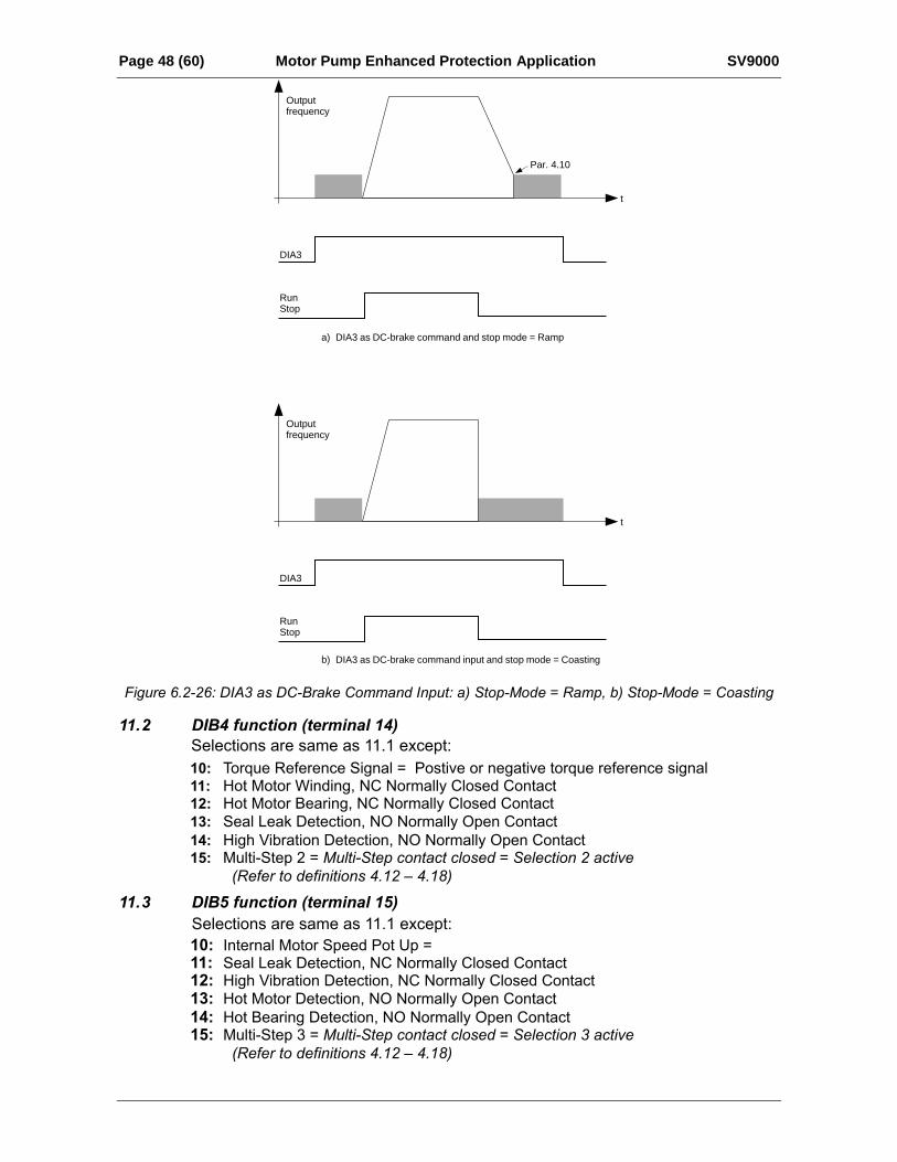
9: DC-braking commandcontact closed =In Stop mode, the DC-braking operates until the contact is opened,see figure 6.2-26. DC-brake current is set with parameter 4.8.
10: Torque controlcontact closed = Forces the motor control mode to torque control, refer to par. 6.1
11: Hot Motor Detection: NC contact open = hot motor detected. Warning or Faultdisplayed based on P7.21 selection.
Hot Bearing Detection: NC contact open = hot bearing detected. Warning or Faultdisplayed based on P7.22 selection.
Seal Leak Detection: NO contact closed = Warning or Fault displayed based onP7.23 selection.
High Vibration Detection: NO contact closed = Warning or Fault displayed based onP7.24 selection.
Multi-Step 1 = Multi-Step contact closed = Selection 1 active (refer to par. 4.12 – 4.18)
12:
13:
14:
15:
Page 48 (60) Motor Pump Enhanced Protection Application SV9000
DIA3
a) DIA3 as DC-brake command and stop mode = Ramp
b) DIA3 as DC-brake command input and stop mode = Coasting
RunStop
DIA3
RunStop
Par. 4.10
Outputfrequency
t
Outputfrequency
t
Figure 6.2-26: DIA3 as DC-Brake Command Input: a) Stop-Mode = Ramp, b) Stop-Mode = Coasting
11.2 DIB4 function (terminal 14)
10: Torque Reference Signal = Postive or negative torque reference signal 11: Hot Motor Winding, NC Normally Closed Contact12: Hot Motor Bearing, NC Normally Closed Contact13: Seal Leak Detection, NO Normally Open Contact14: High Vibration Detection, NO Normally Open Contact15: Multi-Step 2 = Multi-Step contact closed = Selection 2 active
(Refer to definitions 4.12 – 4.18)
10: Internal Motor Speed Pot Up =11: Seal Leak Detection, NC Normally Closed Contact12: High Vibration Detection, NC Normally Closed Contact13: Hot Motor Detection, NO Normally Open Contact14: Hot Bearing Detection, NO Normally Open Contact15: Multi-Step 3 = Multi-Step contact closed = Selection 3 active
(Refer to definitions 4.12 – 4.18)
11.3 DIB5 function (terminal 15)Selections are same as 11.1 except:
Selections are same as 11.1 except:
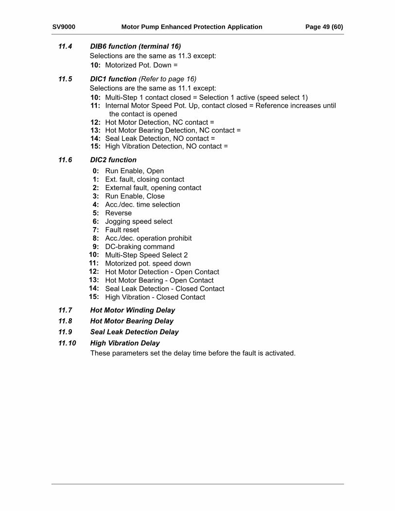
SV9000 Motor Pump Enhanced Protection Application Page 49 (60)
11.4 DIB6 function (terminal 16)Selections are the same as 11.3 except:
10: Motorized Pot. Down =
11: Internal Motor Speed Pot. Up, contact closed = Reference increases until the contact is opened
12: Hot Motor Detection, NC contact =13: Hot Motor Bearing Detection, NC contact =14: Seal Leak Detection, NO contact =15:
11.5 DIC1 function (Refer to page 16)Selections are the same as 11.1 except:10: Multi-Step 1 contact closed = Selection 1 active (speed select 1)
High Vibration Detection, NO contact =
11.6 DIC2 function
0:1:2:3:4:5:6:7:8:9:
Run Enable, OpenExt. fault, closing contactExternal fault, opening contactRun Enable, CloseAcc./dec. time selectionReverseJogging speed selectFault resetAcc./dec. operation prohibitDC-braking commandMulti-Step Speed Select 2Motorized pot. speed downHot Motor Detection - Open ContactHot Motor Bearing - Open ContactSeal Leak Detection - Closed ContactHigh Vibration - Closed Contact
11.7 Hot Motor Winding Delay
11.8 Hot Motor Bearing Delay
11.9 Seal Leak Detection Delay
11.10 High Vibration Delay
These parameters set the delay time before the fault is activated.
10:11:12:13:14:15:
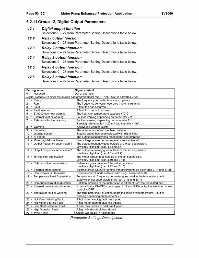
Page 50 (60) Motor Pump Enhanced Protection Application SV9000
6.2.11 Group 12, Digital Output Parameters
12.1 Digital output function
Setting value Signal content0 = Not used Out of operationDigital output DO1 sinks the current and programmable relay (RO1, RO2) is activated when:1 = Ready The frequency converter is ready to operate2 = Run The frequency converter operates (motor is running)3 = Fault A fault trip has occurred4 = Fault inverted A fault trip has not occurred5 = SV9000 overheat warning The heat-sink temperature exceeds +70oC6 = External fault or warning Fault or warning depending on parameter 7.27 = Reference fault or warning Fault or warning depending on parameter 7.1 -
if analog reference is 4 – 20 mA and signal is <4mA8 = Warning Always if a warning exists9 = Reversed The reverse command has been selected10 = Jogging speed Jogging speed has been selected with digital input11 = At speed The output frequency has reached the set reference12 = Motor regulator activated Overvoltage or overcurrent regulator was activated13 = Output frequency supervision 1 The output frequency goes outside of the set supervision.
Low limit/ High limit (par. 3.6 and 3.7)14 = Output frequency supervision 2 The output frequency goes outside of the set supervision.
Low limit/ High limit (par. 3.8 and 3.9)15 = Torque limit supervision The motor torque goes outside of the set supervision.
Low limit/ High limit (par. 3.10 and 3.11)16 = Reference limit supervision Reference goes outside of the set supervision.
Low limit/ High limit (par. 3.12 and 3.13)17 = External brake control External brake ON/OFF control with programmable delay (par 3.14 and 3.15)18 = Control from I/O terminals External control mode selected with progr. push-button #219 = Temperature Limit Supervision Temperature on frequency converter goes outside the temperature limit
supervision set supervision limits (par. 3.16 and 3.17)20 = Unrequested rotation direction Rotation direction of the motor shaft is different from the requested one21 = External brake control inverted External brake ON/OFF control (par. 3.14 and 3.15), output active when brake
control is OFF22 = Thermistor fault or warning The terminator input of option board indicates overtemperature. Fault or
warning depending on parameter 7.1923 = Hot Motor Winding Fault A hot motor winding fault has tripped24 = Hot Motor Bearing Fault A hot motor bearing fault has tripped25 = Seal Seat Detection Fault A seal leak detection fault has tripped26 = High Vibration Fault A high vibration fault has tripped
Parameter Settings Descriptions27 = Warn Flash Output will toggle in Flash mode
Selections 0 – 27 from Parameter Setting Descriptions table below.
12.2 Relay output functionSelections 0 – 27 from Parameter Setting Descriptions table below.
12.3 Relay 2 output functionSelections 0 – 27 from Parameter Setting Descriptions table below.
12.4 Relay 3 output function
12.5 Relay 4 output functionSelections 0 – 27 from Parameter Setting Descriptions table below.
12.6 Relay 5 output functionSelections 0 – 27 from Parameter Setting Descriptions table below.
Selections 0 – 27 from Parameter Setting Descriptions table below.
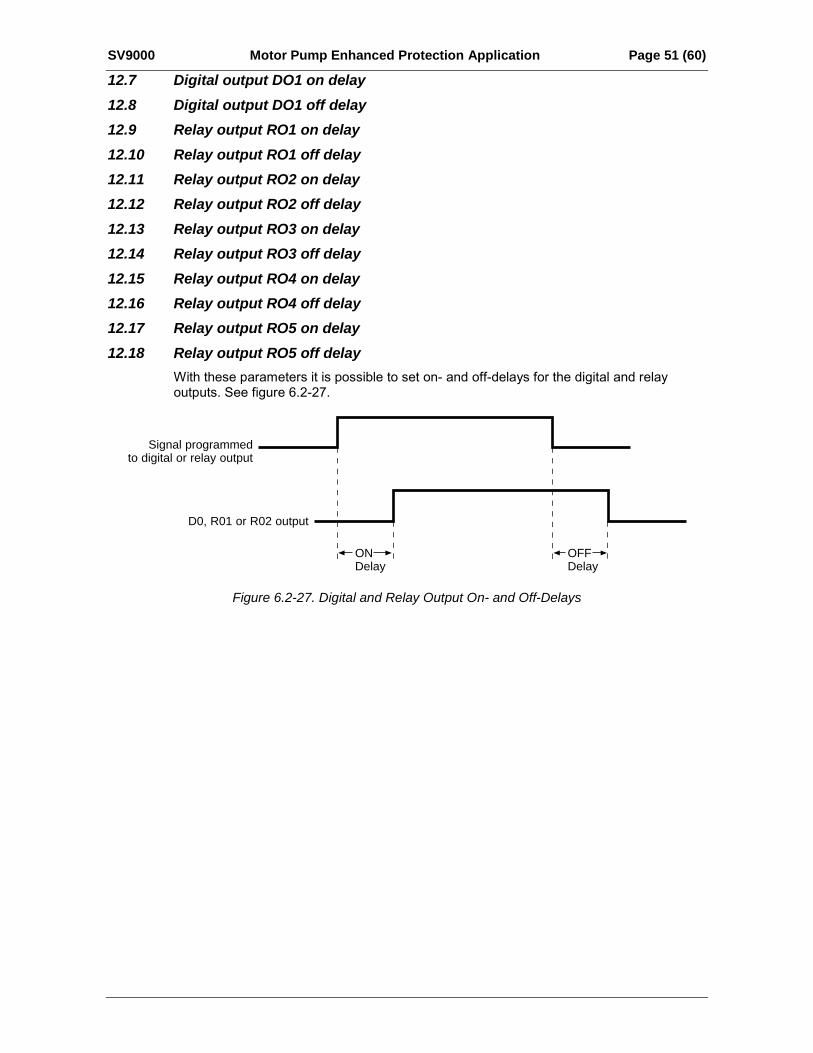
SV9000 Motor Pump Enhanced Protection Application Page 51 (60)
12.7 Digital output DO1 on delay12.8 Digital output DO1 off delay12.9 Relay output RO1 on delay12.10 Relay output RO1 off delay12.11 Relay output RO2 on delay12.12 Relay output RO2 off delay12.13 Relay output RO3 on delay12.14 Relay output RO3 off delay12.15 Relay output RO4 on delay12.16 Relay output RO4 off delay12.17 Relay output RO5 on delay12.18 Relay output RO5 off delay
With these parameters it is possible to set on- and off-delays for the digital and relayoutputs. See figure 6.2-27.
OFFDelay
ONDelay
D0, R01 or R02 output
Signal programmedto digital or relay output
Figure 6.2-27. Digital and Relay Output On- and Off-Delays
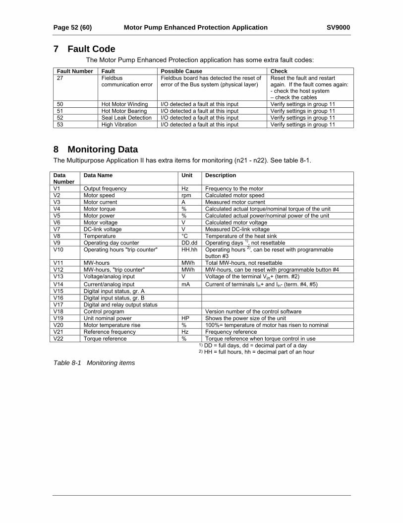
Page 52 (60) Motor Pump Enhanced Protection Application SV9000
7 Fault CodeThe Motor Pump Enhanced Protection application has some extra fault codes:
Fault Number Fault Possible Cause Check27 Fieldbus
communication errorFieldbus board has detected the reset oferror of the Bus system (physical layer)
Reset the fault and restartagain. If the fault comes again:- check the host system check the cables
50 Hot Motor Winding I/O detected a fault at this input Verify settings in group 1151 Hot Motor Bearing I/O detected a fault at this input Verify settings in group 1152 Seal Leak Detection I/O detected a fault at this input Verify settings in group 1153 High Vibration I/O detected a fault at this input Verify settings in group 11
8 Monitoring DataThe Multipurpose Application II has extra items for monitoring (n21 - n22). See table 8-1.
DataNumber
Data Name Unit Description
V1 Output frequency Hz Frequency to the motorV2 Motor speed rpm Calculated motor speedV3 Motor current A Measured motor currentV4 Motor torque % Calculated actual torque/nominal torque of the unitV5 Motor power % Calculated actual power/nominal power of the unitV6 Motor voltage V Calculated motor voltageV7 DC-link voltage V Measured DC-link voltageV8 Temperature °C Temperature of the heat sinkV9 Operating day counter DD.dd Operating days 1), not resettableV10 Operating hours "trip counter" HH.hh Operating hours 2), can be reset with programmable
button #3V11 MW-hours MWh Total MW-hours, not resettableV12 MW-hours, "trip counter" MWh MW-hours, can be reset with programmable button #4V13 Voltage/analog input V Voltage of the terminal Vin+ (term. #2)V14 Current/analog input mA Current of terminals Iin+ and Iin- (term. #4, #5)V15 Digital input status, gr. AV16 Digital input status, gr. BV17 Digital and relay output statusV18 Control program Version number of the control softwareV19 Unit nominal power HP Shows the power size of the unitV20 Motor temperature rise % 100%= temperature of motor has risen to nominalV21 Reference frequency Hz Frequency referenceV22 Torque reference % Torque reference when torque control in use
1) DD = full days, dd = decimal part of a day2) HH = full hours, hh = decimal part of an hour
Table 8-1 Monitoring items
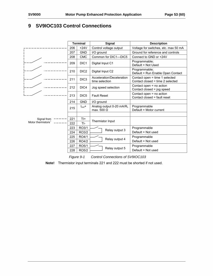
SV9000 Motor Pump Enhanced Protection Application Page 53 (60)
9 SV9IOC103 Control Connections
Terminal Signal Description206 +24V Control voltage output Voltage for switches, etc. max 50 mA207 GND I/O ground Ground for reference and controls208 CMC Common for DIC1DIC5 Connect to GND or +24V
209 DIC1 Digital Input C1 Programmable;Default = Not Used
210 DIC2 Digital Input C2 Programmable;Default = Run Enable Open Contact
211 DIC3 Acceleration/Decelerationtime selection
Contact open = time 1 selectedContact closed = time 2 selected
212 DIC4 Jog speed selection Contact open = no actionContact closed = jog speed
213 DIC5 Fault Reset Contact open = no actionContact closed = fault reset
214 GND I/O ground
215 Iout+ Analog output 0-20 mA/RLmax. 500 Ω
ProgrammableDefault = Motor current
221 TI+222 TI-
Thermistor Input
223 RO3/1224 RO3/2
Relay output 3ProgrammableDefault = Not used
225 RO4/1226 RO4/2
Relay output 4ProgrammableDefault = Not used
227 RO5/1228 RO5/2 Relay output 5
ProgrammableDefault = Not used
Figure 9-1 Control Connections of SV9IOC103
Note! Thermistor input terminals 221 and 222 must be shorted if not used.
Signal fromMotor thermistors1
Page 54 (60) Motor Pump Enhanced Protection Application SV9000
Eaton Electrical1000 Cherrington ParkwayMoon Township, PA 15108-4312USAtel: 1-800-525-2000www.eatonelectrical.com
© 2004 Eaton CorporationAll Rights ReservedPrinted in USAPublication No. MN04001002E/CPGJune 2004
Company Information
Eaton Electrical Inc. is a global leader in electrical control, power distribution, and industrial automation products and services. Through advanced product development, world-class manufacturing methods, and global engineering services and support, Eaton Electrical
®
provides customer-driven solutions under brand names such as Cutler-Hammer
®
, Durant
®
, Heinemann
®
, Holec
®
and MEM
®
, which globally serve the changing needs of the industrial, utility, light commercial, residential, and OEM markets. For more information, visit
www.eatonelectrical.com
.
Eaton Corporation is a global diversified industrial manufacturer with 2002 sales of $7.2 billion that is a leader in fluid power systems; electrical power quality, distribution and control; automotive engine air management and fuel economy; and intelligent drivetrain systems for fuel economy and safety in trucks. Eaton has 51,000 employees and sells products in more than 50 countries. For more information, visit
www.eaton.com
.


![Professional Setting Guide...7 Focus Mode: Choose “Single AF” (AF‑S) and “Single-Point AF”! Choose [Single AF] (AF‑S) for [Focus mode] and select [Single-point AF] for](https://static.fdocuments.in/doc/165x107/61025cabf876b23a8126b5d8/professional-setting-guide-7-focus-mode-choose-aoesingle-afa-afas-and.jpg)