R77 Titanium Full-System Exhaust with Carbon Fiber Sleeve ...
RESEARCHampDEVELOPMENT OF AMERICA INC
wwwyoshimura-rdcom
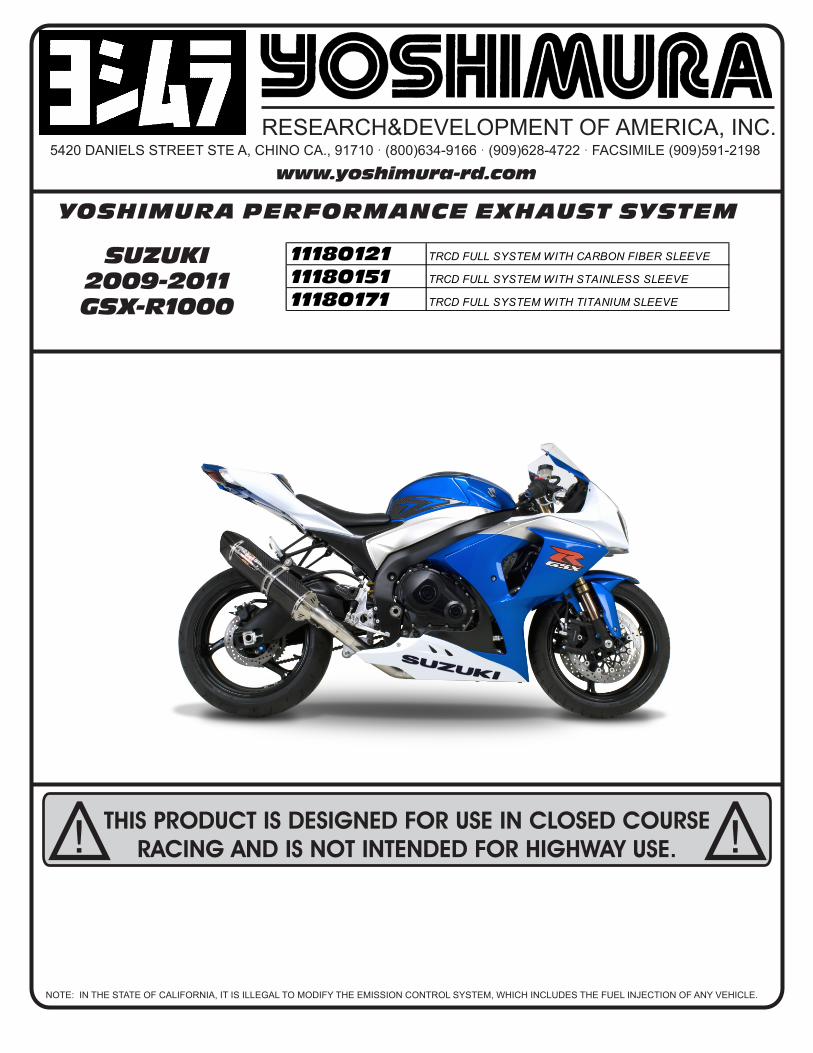
YOSHIMURA PERFORMANCE EXHAUST SYSTEM
11180121 TRCD FULL SYSTEM WITH CARBON FIBER SLEEVE
11180151 TRCD FULL SYSTEM WITH STAINLESS SLEEVE
11180171 TRCD FULL SYSTEM WITH TITANIUM SLEEVE
NOTE IN THE STATE OF CALIFORNIA IT IS ILLEGAL TO MODIFY THE EMISSION CONTROL SYSTEM WHICH INCLUDES THE FUEL INJECTION OF ANY VEHICLE
5420 DANIELS STREET STE A CHINO CA 91710 middot (800)634-9166 middot (909)628-4722 middot FACSIMILE (909)591-2198
SUZUKI 2009-2011GSX-R1000
THIS PRODUCT IS DESIGNED FOR USE IN CLOSED COURSE RACING AND IS NOT INTENDED FOR HIGHWAY USE
Installation Procedures Page 2
Caution Exhaust system can be extremely hot Let motorcycle cool down before beginning installation Always wear hand and eye protection and take precautionary measures to avoid injury
Note Read through all instructions before beginning installation
Tools NeededMetric Socket Set38rdquo ratchet and extensionMetric Combination Wrench SetMetric Allen Wrench Set Torque WrenchSmall Flat Head Screwdriver
Installation Steps
Fig 1
Fig 2
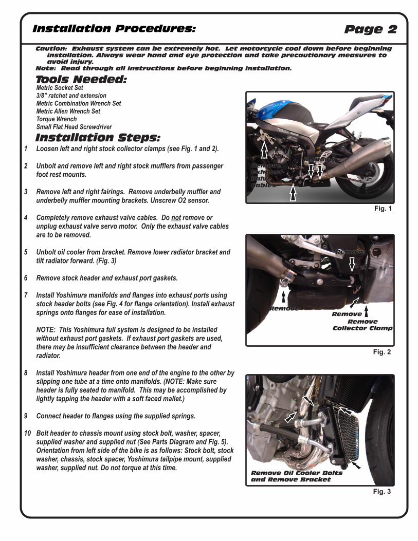
1 Loosen left and right stock collector clamps (see Fig 1 and 2)
2 Unbolt and remove left and right stock mufflers from passenger foot rest mounts
3 Remove left and right fairings Remove underbelly muffler and underbelly muffler mounting brackets Unscrew O2 sensor
4 Completely remove exhaust valve cables Do not remove or unplug exhaust valve servo motor Only the exhaust valve cables are to be removed
5 Unbolt oil cooler from bracket Remove lower radiator bracket and tilt radiator forward (Fig 3)
6 Remove stock header and exhaust port gaskets
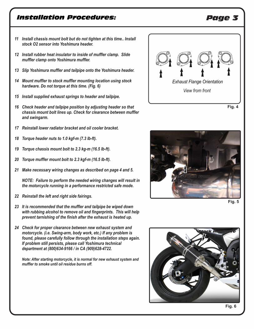
7 Install Yoshimura manifolds and flanges into exhaust ports using stock header bolts (see Fig 4 for flange orientation) Install exhaust springs onto flanges for ease of installation
NOTE This Yoshimura full system is designed to be installed
without exhaust port gaskets If exhaust port gaskets are used there may be insufficient clearance between the header and radiator
8 Install Yoshimura header from one end of the engine to the other by slipping one tube at a time onto manifolds (NOTE Make sure header is fully seated to manifold This may be accomplished by lightly tapping the header with a soft faced mallet)
9 Connect header to flanges using the supplied springs
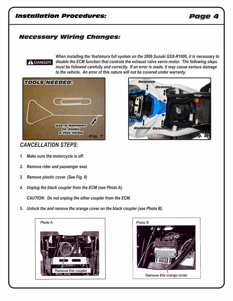
10 Bolt header to chassis mount using stock bolt washer spacer supplied washer and supplied nut (See Parts Diagram and Fig 5) Orientation from left side of the bike is as follows Stock bolt stock washer chassis stock spacer Yoshimura tailpipe mount supplied washer supplied nut Do not torque at this time
RemoveRemoveExhaustValveCables
Remove
RemoveCollector Clamp
Remove
Remove
Fig 3
Remove Oil Cooler Bolts and Remove Bracket
Installation Procedures Page 3
11 Install chassis mount bolt but do not tighten at this time Install stock O2 sensor into Yoshimura header
12 Install rubber heat insulator to inside of muffler clamp Slide muffler clamp onto Yoshimura muffler
13 Slip Yoshimura muffler and tailpipe onto the Yoshimura header
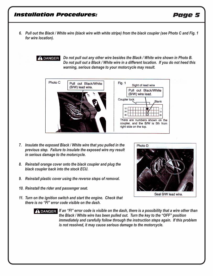
14 Mount muffler to stock muffler mounting location using stock hardware Do not torque at this time (Fig 6)
15 Install supplied exhaust springs to header and tailpipe
16 Check header and tailpipe position by adjusting header so that chassis mount bolt lines up Check for clearance between muffler and swingarm
17 Reinstall lower radiator bracket and oil cooler bracket
18 Torque header nuts to 10 kgf-m (73 lb-ft)
19 Torque chassis mount bolt to 23 kg-m (165 lb-ft)
20 Torque muffler mount bolt to 23 kgf-m (165 lb-ft)
21 Make necessary wiring changes as described on page 4 and 5
NOTE Failure to perform the needed wiring changes will result in the motorcycle running in a performance restricted safe mode
22 Reinstall the left and right side fairings
23 It is recommended that the muffler and tailpipe be wiped down with rubbing alcohol to remove oil and fingerprints This will help prevent tarnishing of the finish after the exhaust is heated up
24 Check for proper clearance between new exhaust system and motorcycle (ie Swing-arm body work etc) If any problem is found please carefully follow through the installation steps again If problem still persists please call Yoshimura technical department at (800)634-9166 in CA (909)628-4722
Note After starting motorcycle it is normal for new exhaust system and muffler to smoke until oil residue burns off
Fig 4
View from front
Fig 5
Insert Bolt FromLeft Side
Fig 6
Stock Hardware
Installation Procedures Page 4
Necessary Wiring Changes
When installing the Yoshimura full system on the 2009 Suzuki GSX-R1000 it is necessary to disable the ECM function that controls the exhaust valve servo motor The following steps must be followed carefully and correctly If an error is made it may cause serious damage to the vehicle An error of this nature will not be covered under warranty
CANCELLATION STEPS
1 Make sure the motorcycle is off
2 Remove rider and passenger seat
3 Remove plastic cover (See Fig 8)
4 Unplug the black coupler from the ECM (see Photo A)
CAUTION Do not unplug the other coupler from the ECM
5 Unlock the and remove the orange cover on the black coupler (see Photo B)
Use a hammerto make
a flat head
TOOLS NEEDED
Remove
Remove
Fig 8Fig 7
Remove
Remove
Installation Procedures Page 5
7 Insulate the exposed Black White wire that you pulled in the previous step Failure to insulate the exposed wire my result in serious damage to the motorcycle
8 Reinstall orange cover onto the black coupler and plug the black coupler back into the stock ECU
9 Reinstall plastic cover using the reverse steps of removal
10 Reinstall the rider and passenger seat
11 Turn on the ignition switch and start the engine Check that there is no ldquoFIrdquo error code visible on the dash
6 Pull out the Black White wire (black wire with white stripe) from the black coupler (see Photo C and Fig 1 for wire location)
Do not pull out any other wire besides the Black White wire shown in Photo B Do not pull out a Black White wire in a different location If you do not heed this warning serious damage to your motorcycle may result
If an ldquoFIrdquo error code is visible on the dash there is a possibility that a wire other than the Black White wire has been pulled out Turn the key to the ldquoOFFrdquo position immediately and carefully follow through the instruction steps again If this problem is not resolved it may cause serious damage to the motorcycle
Installation Procedures Page 6
NOTE The Yoshimura header includes an adapter for the O2 sensor bung to be used with the M12X125 OEM O2 sensor In the case that an aftermarket O2 sensor is utilized requiring an M18X15 thread pitch remove the adapter shown in Fig 9 to reveal the M18X15 bung
Fig 9
Parts Diagram
Part List Page 7
NO DESCRIPTION QTY PART
1 Yoshimura Stainless Steel Manifold 4 1118SMT
2 Yoshimura Stainless Steel Flange 4 1118SDY
3 Small Race Spring 16 RACE-SPX-1
4 Yoshimura Header 1 11181-404F
5 Stainless Steel Muffler Clamp 1
Stainless Steel or Titanium Sleeve use CTS812X
Carbon Fiber Sleeve use CTS812
6 Yoshimura Tailpipe 1 1118-419
7 Yoshimura TRCD Muffler 1
with Carbon Fiber Sleeve CRTRCD146W
with Stainless Steel Sleeve SRTRCD146W
with Titanium Sleeve TRTRCD146W
8 8mm Nut 1 8MMNUT
9 8mm Washer XL 1 8MMWASHERXL
Muffler Clamp Heat Insulator 1 HT SHLDR77
Spring Puller Tool 1 ST-200
Yoshimura Sticker Kit Sheet 1 17029
111801(215171)
SS
S
S
S
S5
7
8
6
9
4
1
2
3
3
33
3
S=STOCK
Installation Procedures Page 2
Caution Exhaust system can be extremely hot Let motorcycle cool down before beginning installation Always wear hand and eye protection and take precautionary measures to avoid injury
Note Read through all instructions before beginning installation
Tools NeededMetric Socket Set38rdquo ratchet and extensionMetric Combination Wrench SetMetric Allen Wrench Set Torque WrenchSmall Flat Head Screwdriver
Installation Steps
Fig 1
Fig 2
1 Loosen left and right stock collector clamps (see Fig 1 and 2)
2 Unbolt and remove left and right stock mufflers from passenger foot rest mounts
3 Remove left and right fairings Remove underbelly muffler and underbelly muffler mounting brackets Unscrew O2 sensor
4 Completely remove exhaust valve cables Do not remove or unplug exhaust valve servo motor Only the exhaust valve cables are to be removed
5 Unbolt oil cooler from bracket Remove lower radiator bracket and tilt radiator forward (Fig 3)
6 Remove stock header and exhaust port gaskets
7 Install Yoshimura manifolds and flanges into exhaust ports using stock header bolts (see Fig 4 for flange orientation) Install exhaust springs onto flanges for ease of installation
NOTE This Yoshimura full system is designed to be installed
without exhaust port gaskets If exhaust port gaskets are used there may be insufficient clearance between the header and radiator
8 Install Yoshimura header from one end of the engine to the other by slipping one tube at a time onto manifolds (NOTE Make sure header is fully seated to manifold This may be accomplished by lightly tapping the header with a soft faced mallet)
9 Connect header to flanges using the supplied springs
10 Bolt header to chassis mount using stock bolt washer spacer supplied washer and supplied nut (See Parts Diagram and Fig 5) Orientation from left side of the bike is as follows Stock bolt stock washer chassis stock spacer Yoshimura tailpipe mount supplied washer supplied nut Do not torque at this time
RemoveRemoveExhaustValveCables
Remove
RemoveCollector Clamp
Remove
Remove
Fig 3
Remove Oil Cooler Bolts and Remove Bracket
Installation Procedures Page 3
11 Install chassis mount bolt but do not tighten at this time Install stock O2 sensor into Yoshimura header
12 Install rubber heat insulator to inside of muffler clamp Slide muffler clamp onto Yoshimura muffler
13 Slip Yoshimura muffler and tailpipe onto the Yoshimura header
14 Mount muffler to stock muffler mounting location using stock hardware Do not torque at this time (Fig 6)
15 Install supplied exhaust springs to header and tailpipe
16 Check header and tailpipe position by adjusting header so that chassis mount bolt lines up Check for clearance between muffler and swingarm
17 Reinstall lower radiator bracket and oil cooler bracket
18 Torque header nuts to 10 kgf-m (73 lb-ft)
19 Torque chassis mount bolt to 23 kg-m (165 lb-ft)
20 Torque muffler mount bolt to 23 kgf-m (165 lb-ft)
21 Make necessary wiring changes as described on page 4 and 5
NOTE Failure to perform the needed wiring changes will result in the motorcycle running in a performance restricted safe mode
22 Reinstall the left and right side fairings
23 It is recommended that the muffler and tailpipe be wiped down with rubbing alcohol to remove oil and fingerprints This will help prevent tarnishing of the finish after the exhaust is heated up
24 Check for proper clearance between new exhaust system and motorcycle (ie Swing-arm body work etc) If any problem is found please carefully follow through the installation steps again If problem still persists please call Yoshimura technical department at (800)634-9166 in CA (909)628-4722
Note After starting motorcycle it is normal for new exhaust system and muffler to smoke until oil residue burns off
Fig 4
View from front
Fig 5
Insert Bolt FromLeft Side
Fig 6
Stock Hardware
Installation Procedures Page 4
Necessary Wiring Changes
When installing the Yoshimura full system on the 2009 Suzuki GSX-R1000 it is necessary to disable the ECM function that controls the exhaust valve servo motor The following steps must be followed carefully and correctly If an error is made it may cause serious damage to the vehicle An error of this nature will not be covered under warranty
CANCELLATION STEPS
1 Make sure the motorcycle is off
2 Remove rider and passenger seat
3 Remove plastic cover (See Fig 8)
4 Unplug the black coupler from the ECM (see Photo A)
CAUTION Do not unplug the other coupler from the ECM
5 Unlock the and remove the orange cover on the black coupler (see Photo B)
Use a hammerto make
a flat head
TOOLS NEEDED
Remove
Remove
Fig 8Fig 7
Remove
Remove
Installation Procedures Page 5
7 Insulate the exposed Black White wire that you pulled in the previous step Failure to insulate the exposed wire my result in serious damage to the motorcycle
8 Reinstall orange cover onto the black coupler and plug the black coupler back into the stock ECU
9 Reinstall plastic cover using the reverse steps of removal
10 Reinstall the rider and passenger seat
11 Turn on the ignition switch and start the engine Check that there is no ldquoFIrdquo error code visible on the dash
6 Pull out the Black White wire (black wire with white stripe) from the black coupler (see Photo C and Fig 1 for wire location)
Do not pull out any other wire besides the Black White wire shown in Photo B Do not pull out a Black White wire in a different location If you do not heed this warning serious damage to your motorcycle may result
If an ldquoFIrdquo error code is visible on the dash there is a possibility that a wire other than the Black White wire has been pulled out Turn the key to the ldquoOFFrdquo position immediately and carefully follow through the instruction steps again If this problem is not resolved it may cause serious damage to the motorcycle
Installation Procedures Page 6
NOTE The Yoshimura header includes an adapter for the O2 sensor bung to be used with the M12X125 OEM O2 sensor In the case that an aftermarket O2 sensor is utilized requiring an M18X15 thread pitch remove the adapter shown in Fig 9 to reveal the M18X15 bung
Fig 9
Parts Diagram
Part List Page 7
NO DESCRIPTION QTY PART
1 Yoshimura Stainless Steel Manifold 4 1118SMT
2 Yoshimura Stainless Steel Flange 4 1118SDY
3 Small Race Spring 16 RACE-SPX-1
4 Yoshimura Header 1 11181-404F
5 Stainless Steel Muffler Clamp 1
Stainless Steel or Titanium Sleeve use CTS812X
Carbon Fiber Sleeve use CTS812
6 Yoshimura Tailpipe 1 1118-419
7 Yoshimura TRCD Muffler 1
with Carbon Fiber Sleeve CRTRCD146W
with Stainless Steel Sleeve SRTRCD146W
with Titanium Sleeve TRTRCD146W
8 8mm Nut 1 8MMNUT
9 8mm Washer XL 1 8MMWASHERXL
Muffler Clamp Heat Insulator 1 HT SHLDR77
Spring Puller Tool 1 ST-200
Yoshimura Sticker Kit Sheet 1 17029
111801(215171)
SS
S
S
S
S5
7
8
6
9
4
1
2
3
3
33
3
S=STOCK


![Cable reduction sleeve - Glenair, Inc. · Reduction Sleeve for use with Mechanical Cable Clamp or Basketweave Cable Grip Shell Size Sleeve P/N Sleeve inner diameter [mm] Sleeve outer](https://static.fdocuments.in/doc/165x107/5ec496aef7ac3c7f406c6755/cable-reduction-sleeve-glenair-inc-reduction-sleeve-for-use-with-mechanical.jpg)