SUT-220-AI - Aluminum Trailers - Trailex, Inc. SUT-220-AI Torque wrench, carpenters square, wire...
68
1 SUT-220-AI Torque wrench, carpenters square, wire cutters, Phillips screwdriver, 7/16, 9/16, and 3/4” combination wrenches, ratchet, 9/16, 3/4, 13/16”, and 7/8” sockets. ASSEMBLY REQUIREMENTS *Torque all T-bolt nuts to 35-40 foot pounds. *Check all lights before towing. *Tire pressure not to exceed recommendation on serial tag. *Re-torque wheel nuts after first 25 miles to 80 ft. pounds and periodically thereafter. Failure to follow the assembly instructions could result in serious injury or death. Incorrect assembly or modifications to your trailer will void any specific or implied warranty. For questions or assistance assembling your trailer call 800-282-5042.
Transcript of SUT-220-AI - Aluminum Trailers - Trailex, Inc. SUT-220-AI Torque wrench, carpenters square, wire...
1
SUT-220-AI
Torque wrench, carpenters square, wire cutters, Phillips screwdriver, 7/16, 9/16,
and 3/4” combination wrenches, ratchet, 9/16, 3/4, 13/16”, and 7/8” sockets.
ASSEMBLY REQUIREMENTS
*Torque all T-bolt nuts to 35-40 foot pounds.
*Check all lights before towing.
*Tire pressure not to exceed recommendation on serial tag.
*Re-torque wheel nuts after first 25 miles to 80 ft. pounds and periodically
thereafter.
Failure to follow the assembly instructions could result in serious injury or death.
Incorrect assembly or modifications to your trailer will void any specific or implied
warranty.
For questions or assistance assembling your trailer call 800-282-5042.

2
UNPACK AND IDENTIFY THE FOLLOWING PARTS.
Tongue section
Side rails Rear cross member
Front cross member

3
Rear of spring Front of spring
Axle, spring assemblies and U-bolt hardware.
Tires and fenders
4
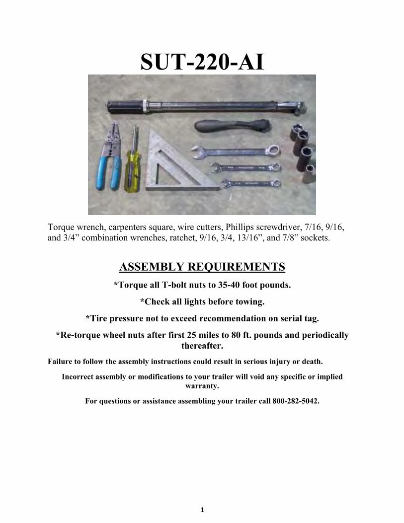
Roller and skid
Front cradle holder Rear cradle holder

5
Light kit, marker light bracket, harness, tail light brackets, 3) hardware bags and
spare parts bag.
Optional step for spare tire carrier
Spare tire carrier for SUT trailers.

6
Loosen the T-bolts and nuts on spare tire carrier. Insert into the underside of the
front tongue at the rear. Once T-bolts are in channel slide towards the coupler.
Position carrier about 18” away from the rear of the front tongue section then
tighten nuts.

7
Tongue assembly
Rear of front tongue section
Loosen the 1 nut at the rear of the front tongue section.
Slide all 4 bolts forward toward the coupler. These will be used later to install the
front roller.
8
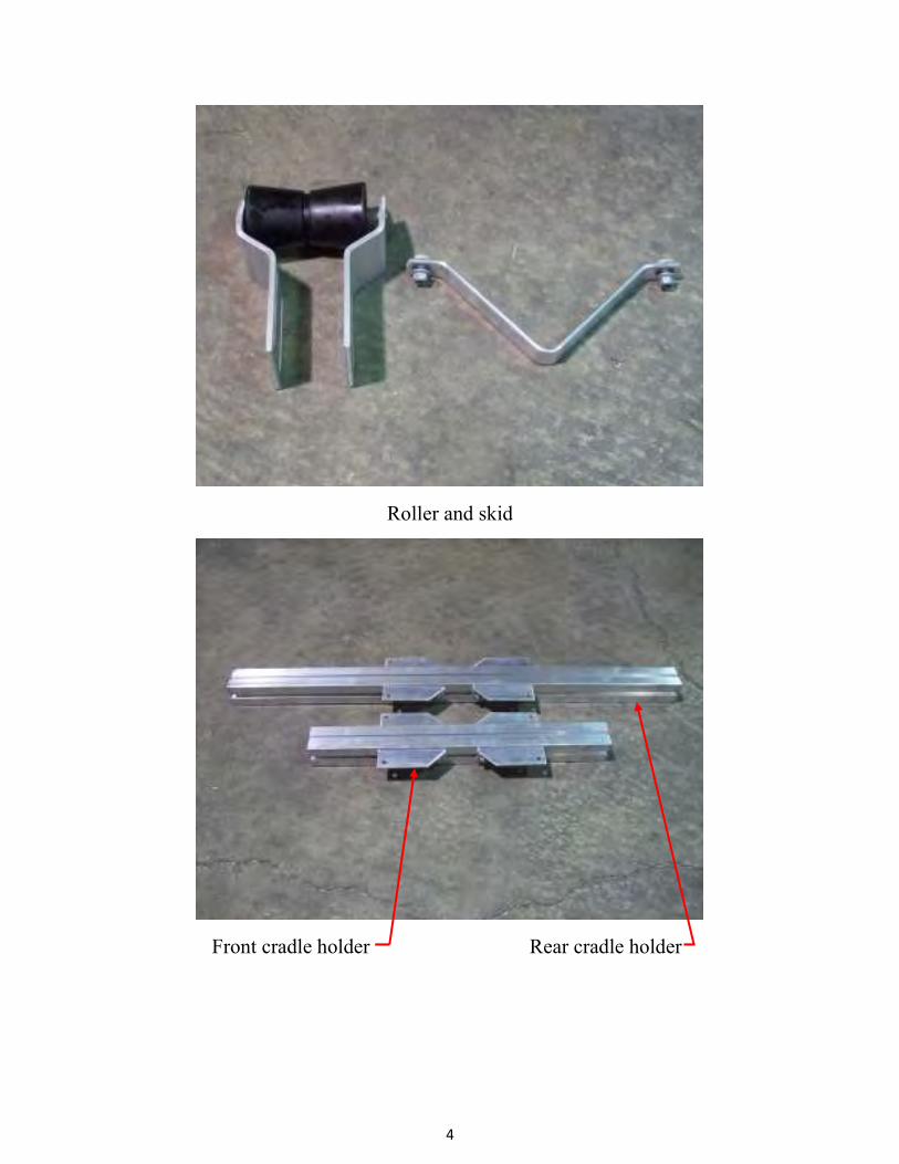
Lay the tongue sections end to end with the splice plates adjacent to each other.
Rear splice plate
Loosen 8 nuts on the rear splice plate.

9
Helpful hint: Place a couple of 2 x 4 under each of the tongue section to make it
level. This will help with alignment and sliding the splice plates into position.
Slide each plate over the adjacent tongue section until the plates are centered over
the gap between the tongue sections.
10
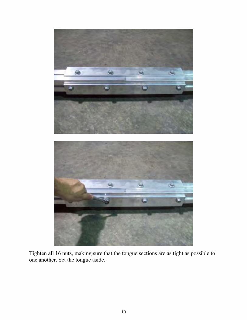
Tighten all 16 nuts, making sure that the tongue sections are as tight as possible to
one another. Set the tongue aside.
11
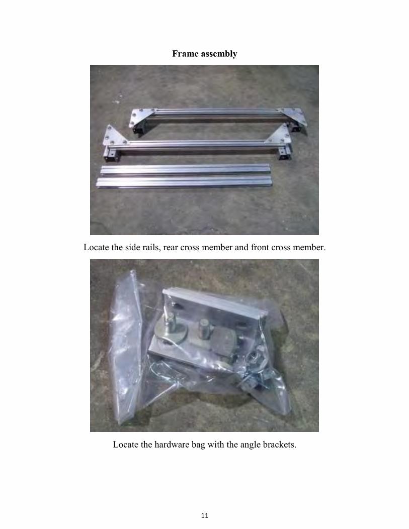
Frame assembly
Locate the side rails, rear cross member and front cross member.
Locate the hardware bag with the angle brackets.
12
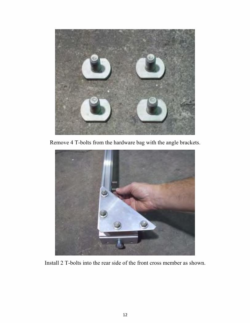
Remove 4 T-bolts from the hardware bag with the angle brackets.
Install 2 T-bolts into the rear side of the front cross member as shown.
13
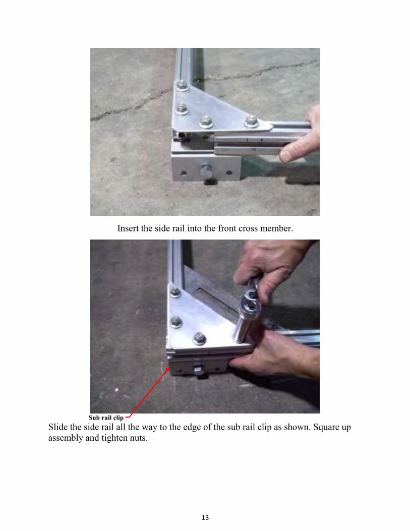
Insert the side rail into the front cross member.
Sub rail clip
Slide the side rail all the way to the edge of the sub rail clip as shown. Square up
assembly and tighten nuts.
14
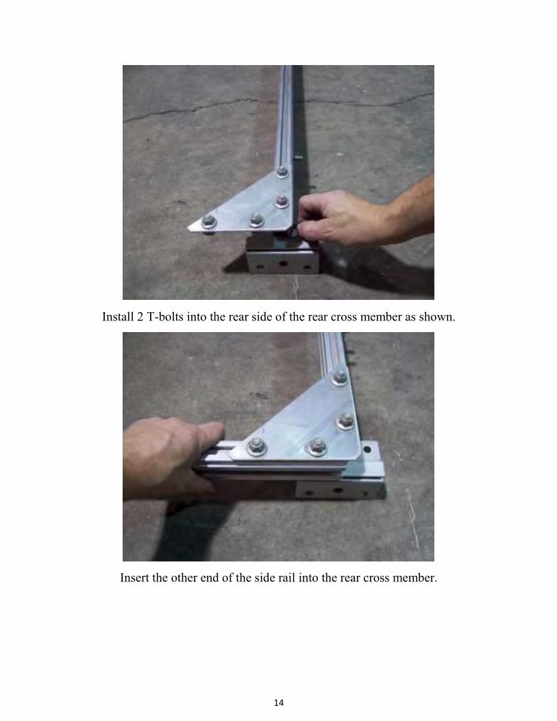
Install 2 T-bolts into the rear side of the rear cross member as shown.
Insert the other end of the side rail into the rear cross member.

15
Sub rail clip
Slide the side rail all the way to the edge of the sub rail clip as shown. The side rail
should be about 1 ½” pass the rear cross member when in position.
Square up and tighten nuts. Repeat the process for the other side at this point.
1 ½”
16
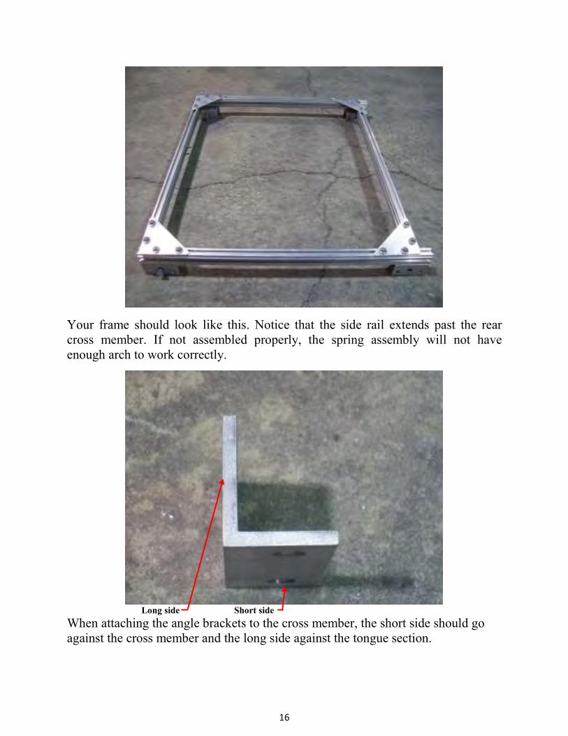
Your frame should look like this. Notice that the side rail extends past the rear
cross member. If not assembled properly, the spring assembly will not have
enough arch to work correctly.
Long side Short side
When attaching the angle brackets to the cross member, the short side should go
against the cross member and the long side against the tongue section.

17
Install the angle brackets on the T-bolts, already in the cross members as shown.
Pencil marks
Align the front and rear left side angle brackets with the pencil marks on the frame.
Square up angle brackets and tighten nuts. Leave brackets on the other side loose at
this point.
Center line pencil mark
18
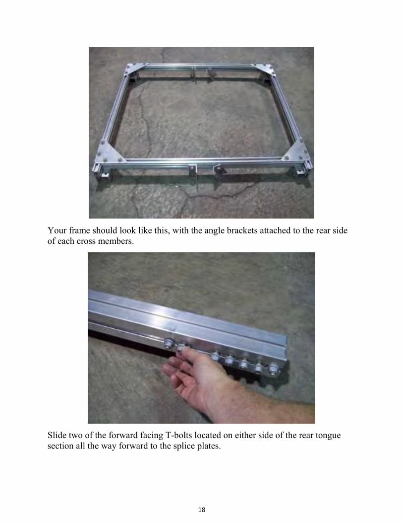
Your frame should look like this, with the angle brackets attached to the rear side
of each cross members.
Slide two of the forward facing T-bolts located on either side of the rear tongue
section all the way forward to the splice plates.

19
These T-bolts will be used to attach the front cradle holder later.
Slide the next two forward facing T-bolt on either side of the rear tongue section to
the pencil marks.
20
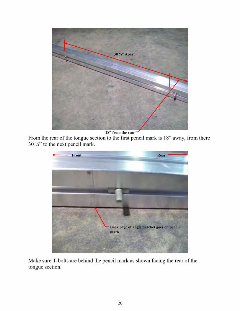
18” from the rear
From the rear of the tongue section to the first pencil mark is 18” away, from there
30 ¼” to the next pencil mark.
Make sure T-bolts are behind the pencil mark as shown facing the rear of the
tongue section.
30 ¼” Apart
Front Rear
Back edge of angle bracket goes on pencil
mark
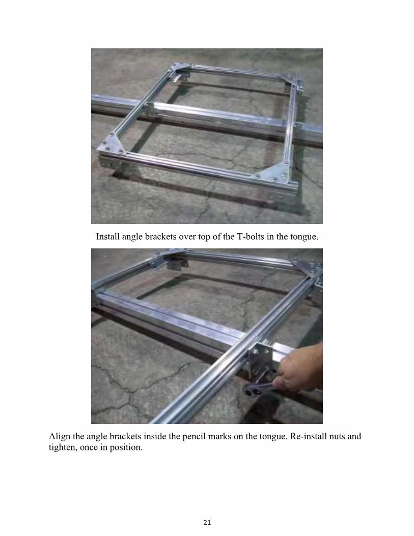
21
Install angle brackets over top of the T-bolts in the tongue.
Align the angle brackets inside the pencil marks on the tongue. Re-install nuts and
tighten, once in position.
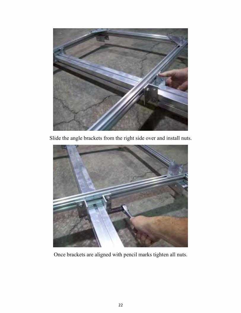
22
Slide the angle brackets from the right side over and install nuts.
Once brackets are aligned with pencil marks tighten all nuts.
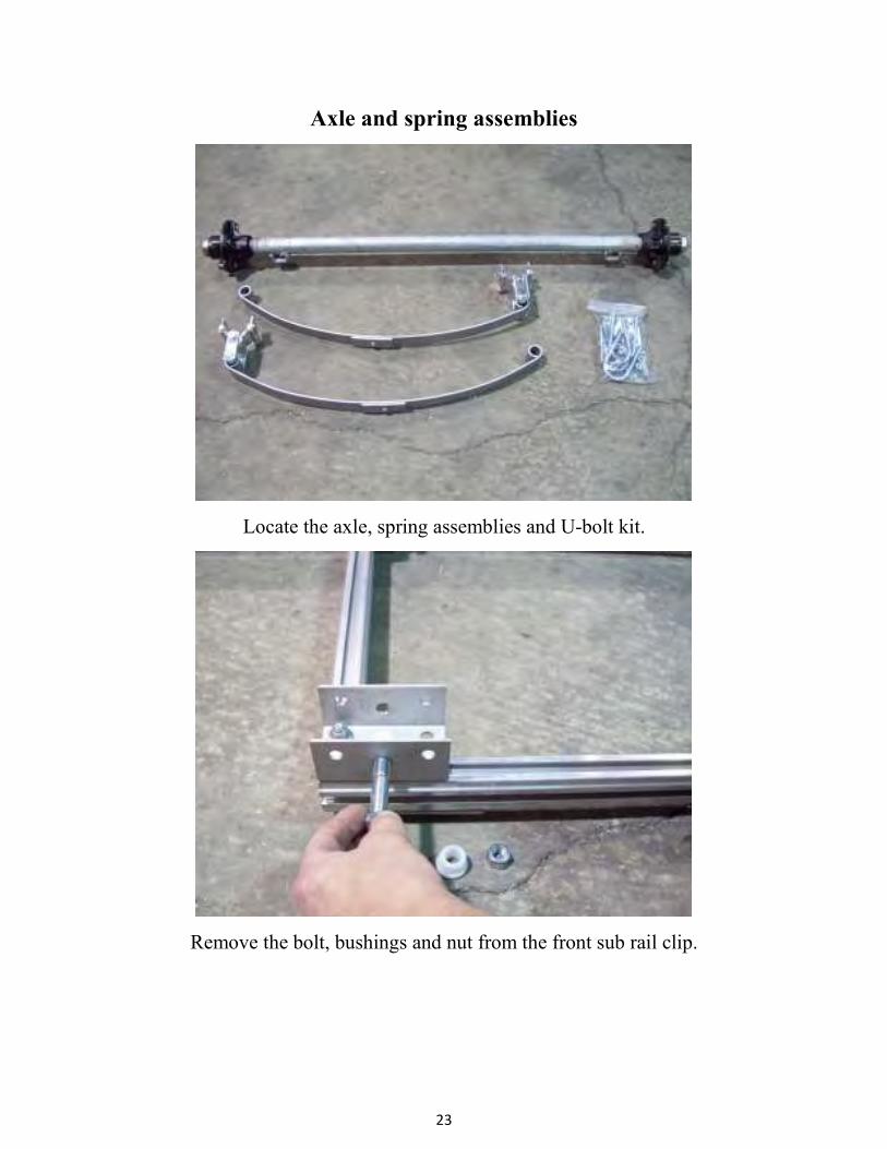
23
Axle and spring assemblies
Locate the axle, spring assemblies and U-bolt kit.
Remove the bolt, bushings and nut from the front sub rail clip.
24
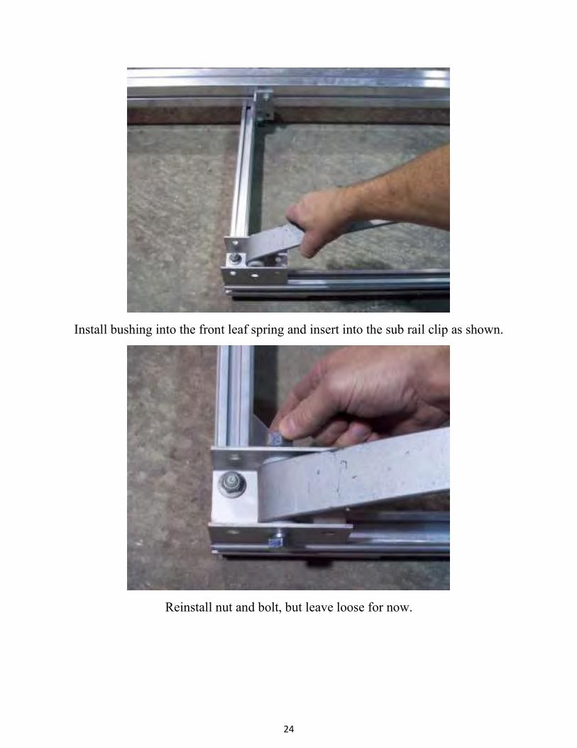
Install bushing into the front leaf spring and insert into the sub rail clip as shown.
Reinstall nut and bolt, but leave loose for now.

25
Remove the two bolts from the shackle holder at the rear of the spring and install
the shackle holder into the rear sub rail clip, with the nuts toward the inside of the
trailer. These nuts can be tightened at this time.
Shackle holder
26
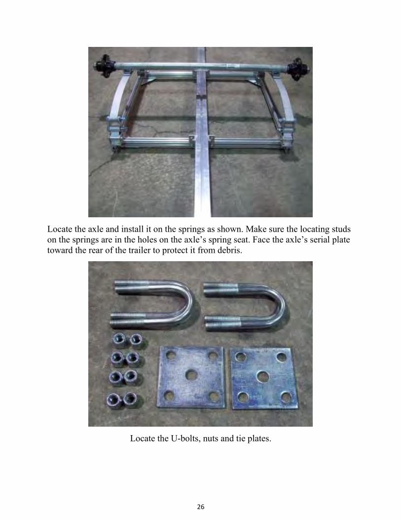
Locate the axle and install it on the springs as shown. Make sure the locating studs
on the springs are in the holes on the axle’s spring seat. Face the axle’s serial plate
toward the rear of the trailer to protect it from debris.
Locate the U-bolts, nuts and tie plates.
27
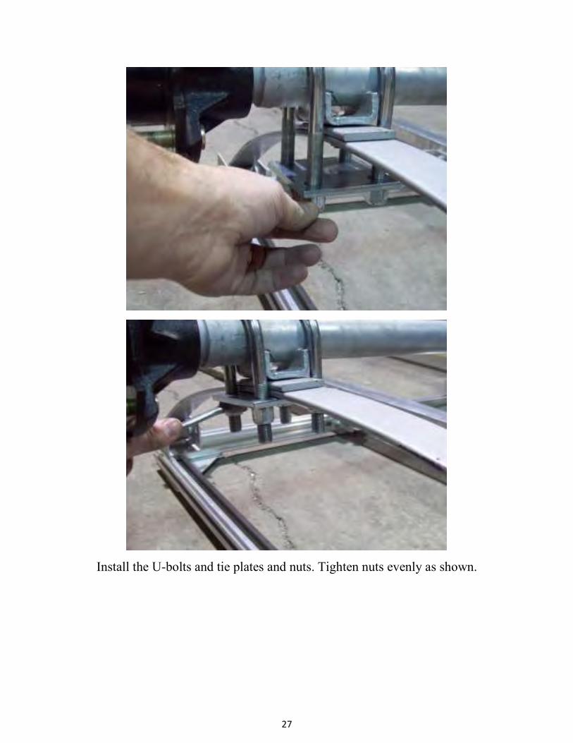
Install the U-bolts and tie plates and nuts. Tighten nuts evenly as shown.

28
Go back and tighten all the spring mounting nuts that were left loose previously.
On the rear shackle, do not over tighten as this will not allow the suspension to
move properly.

29
Your trailer should look like this at this point.
Cradle holders
Locate the front and rear cradle holders. The front cradle holder is the short one.
Front cradle holder
Rear cradle holder
30
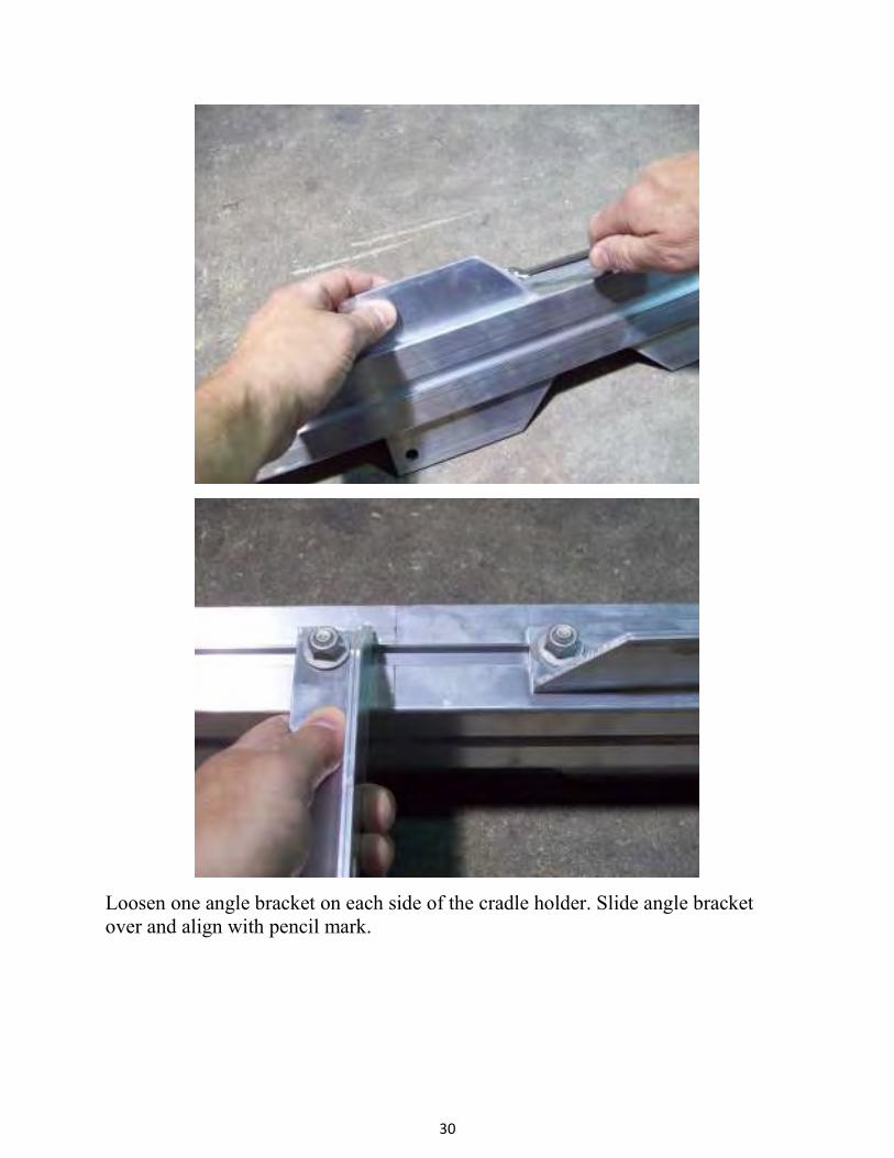
Loosen one angle bracket on each side of the cradle holder. Slide angle bracket
over and align with pencil mark.
31
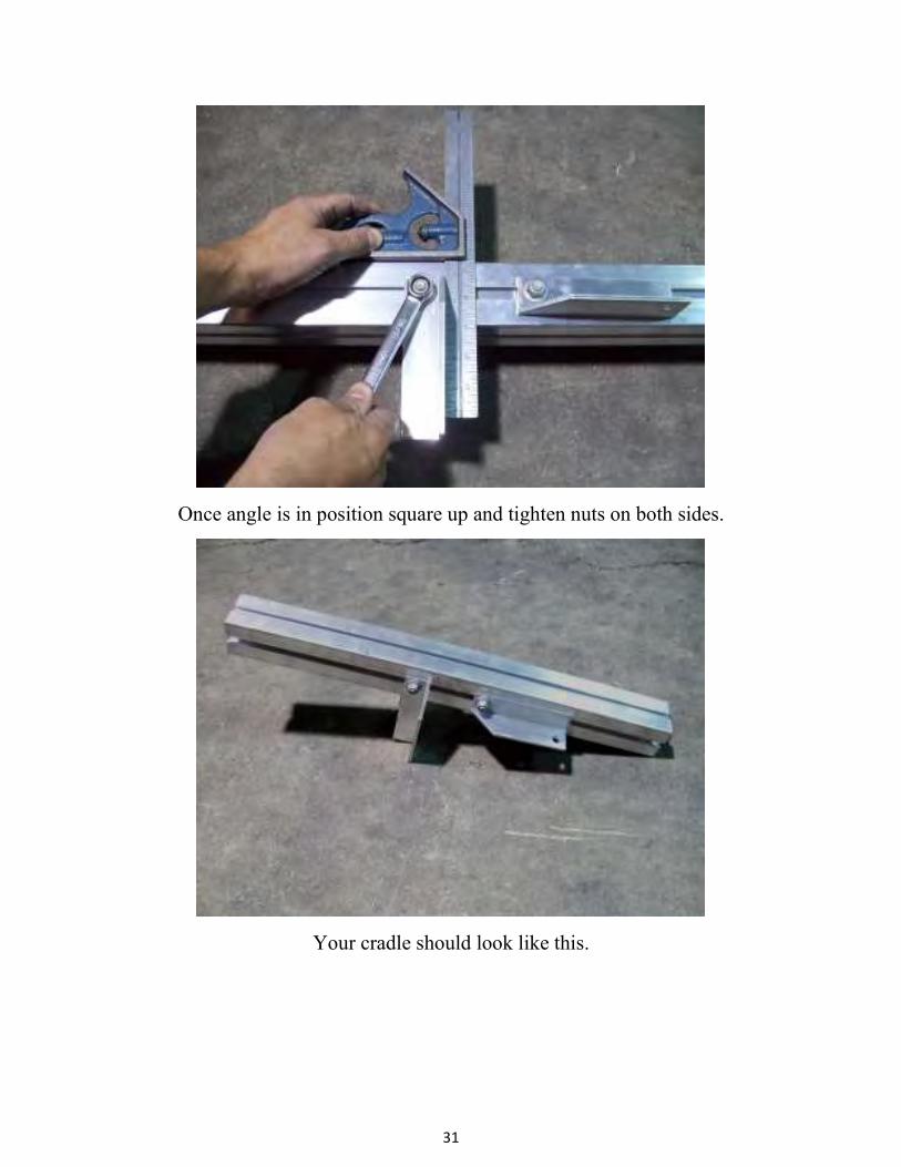
Once angle is in position square up and tighten nuts on both sides.
Your cradle should look like this.

32
Remove the nuts from the T-bolts next to the splice plates on both sides of the
tongue section.
Install angle brackets over T-bolts as shown.

33
Reinstall nuts and tighten.
Loosen nuts on other side now and drop the angle brackets down over T-bolts.

34
Align angle brackets with pencil marks on the cradle holder. Reinstall nuts and
tighten into position.
Pencil marks
35
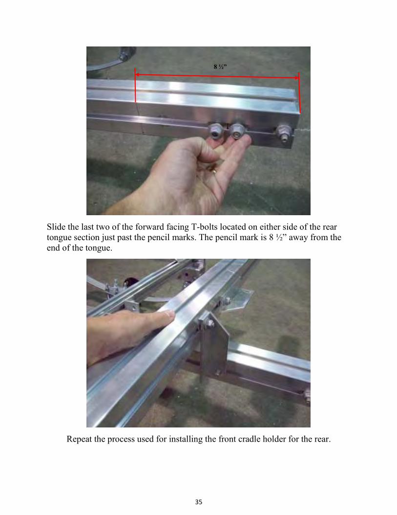
Slide the last two of the forward facing T-bolts located on either side of the rear
tongue section just past the pencil marks. The pencil mark is 8 ½” away from the
end of the tongue.
Repeat the process used for installing the front cradle holder for the rear.
8 ½”
36
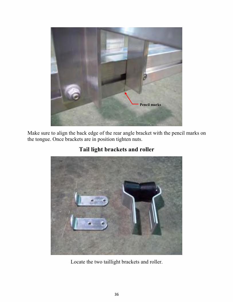
Make sure to align the back edge of the rear angle bracket with the pencil marks on
the tongue. Once brackets are in position tighten nuts.
Tail light brackets and roller
Locate the two taillight brackets and roller.
Pencil marks
37
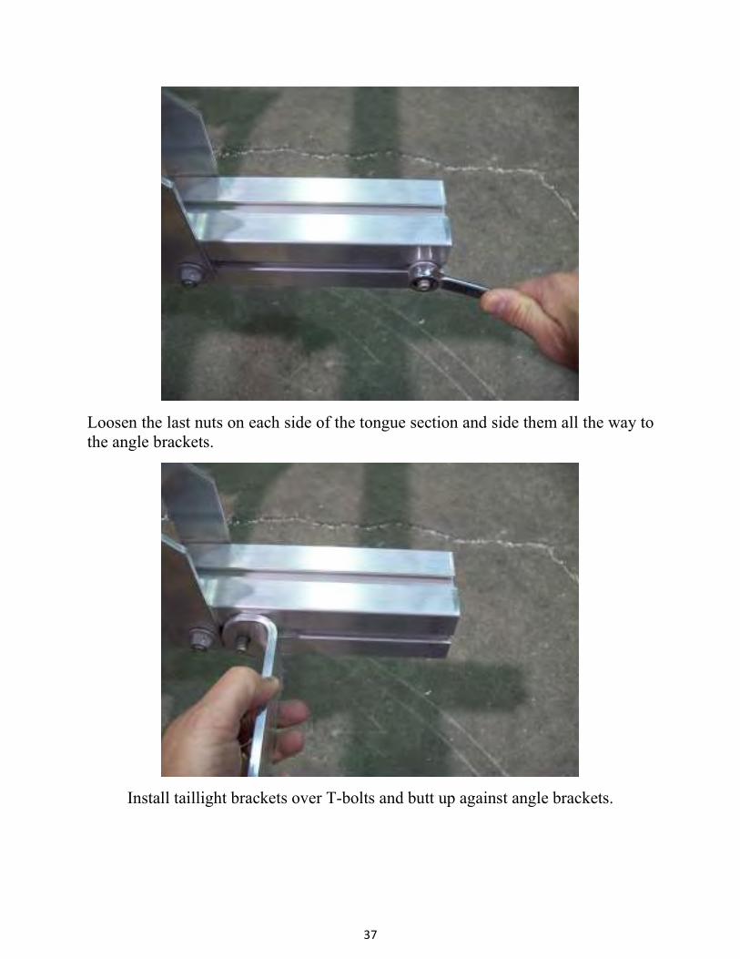
Loosen the last nuts on each side of the tongue section and side them all the way to
the angle brackets.
Install taillight brackets over T-bolts and butt up against angle brackets.

38
Install nuts and tighten.
Locate the two T-bolts on each side of the front of the tongue section. Position
them about 12” away from the coupler and remove nuts. Final position of the roller
will be made when boat is on the trailer.
12”
39
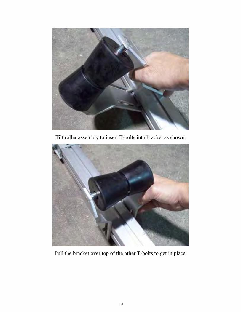
Tilt roller assembly to insert T-bolts into bracket as shown.
Pull the bracket over top of the other T-bolts to get in place.

40
Reinstall nuts and tighten.
Wiring and lights
Locate the tail lights, license plate bracket, 4) carriage bolts and 4) nuts inside the
light kit box.

41
The light with the yellow wires is for the left (drive’s side) of the trailer. Slide the
carriage bolts into the slots in the back of the tail lights.
Install the license plate bracket onto the left taillight as shown.

42
Trailer shown upside down
Install the license plate bracket and left tail light onto the tail light bracket.
Install the white ground wire from the tail light onto the carriage bolt.

43
Trailer shown upside down
Install nuts and tighten. Repeat this process for the right side tail light.
Locate the skid, running light bracket holder, 2) amber running lights, 4) small
Philips screws and 2) ring terminals.
44
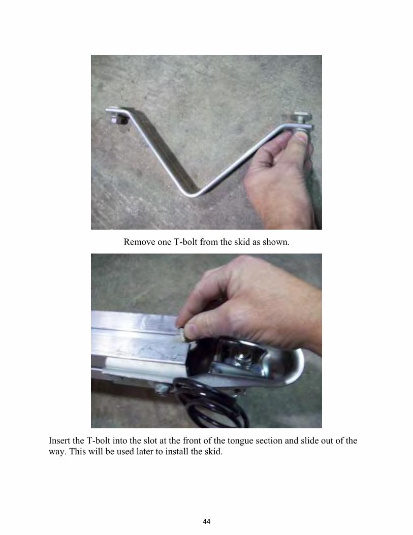
Remove one T-bolt from the skid as shown.
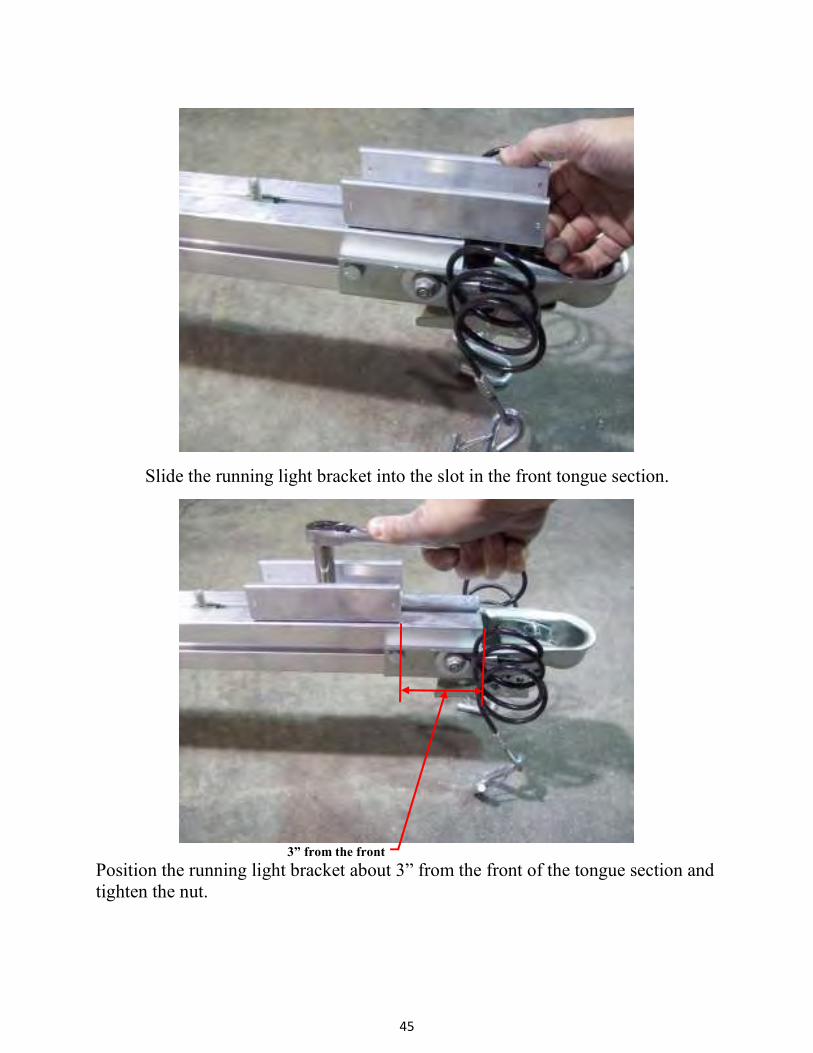
Insert the T-bolt into the slot at the front of the tongue section and slide out of the
way. This will be used later to install the skid.
45
Slide the running light bracket into the slot in the front tongue section.
3” from the front
Position the running light bracket about 3” from the front of the tongue section and
tighten the nut.
46
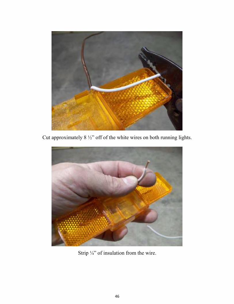
Cut approximately 8 ½” off of the white wires on both running lights.
Strip ¼” of insulation from the wire.

47
Install the ring terminals by crimping the terminal onto the bare wire.
Align the ring terminals with the screw hole nearest the wire on the back of the
running lights. Make sure the wire is routed through the gap on the back of the
light so it does not become pinched when the light is installed.

48
Install the running lights into the pre-drilled holes in the running light bracket
using a Philips screwdriver. Be sure the screw is through the ring terminal on the
back side of the lights. This will supply a ground to the lights.
Locate the wire harness, ring terminal, Philips screw, adhesive backed clamps, and
two blue connectors.
49
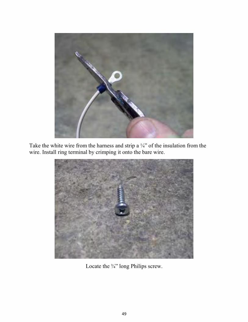
Take the white wire from the harness and strip a ¼” of the insulation from the
wire. Install ring terminal by crimping it onto the bare wire.
Locate the ¾” long Philips screw.
50
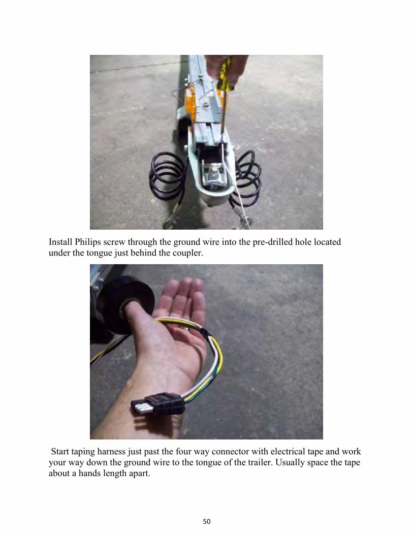
Install Philips screw through the ground wire into the pre-drilled hole located
under the tongue just behind the coupler.
Start taping harness just past the four way connector with electrical tape and work
your way down the ground wire to the tongue of the trailer. Usually space the tape
about a hands length apart.

51
Your wiring harness should look like this when finished.
Extend a tape measure inside the tongue from the rear of the trailer until it
protrudes at the front of the trailer under the coupler.
52
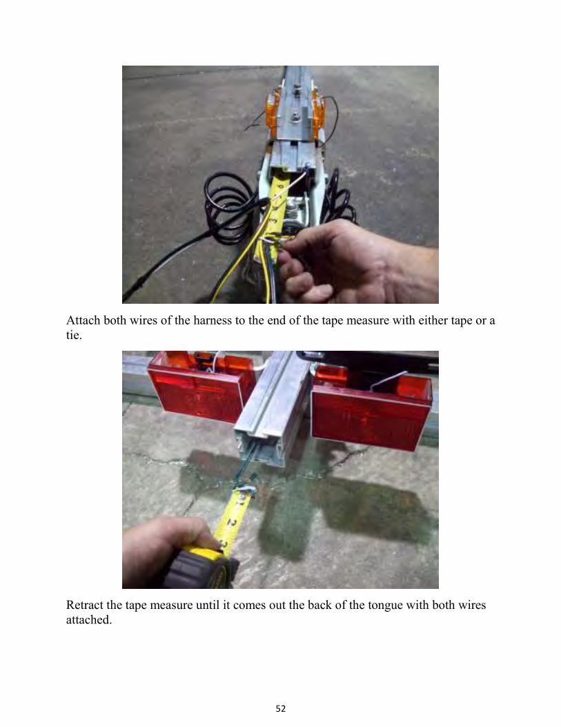
Attach both wires of the harness to the end of the tape measure with either tape or a
tie.
Retract the tape measure until it comes out the back of the tongue with both wires
attached.

53
Locate the black tab at the bottom of the tail light.
Move the tab toward the rear of the trailer and pull up, releasing the bulb assembly
from the light housing.

54
Trim off excess wire, leaving some for adjustment. Strip about a ½” of casing from
the harness.
Loosen the retaining screws and install the color matching wires from the harness
onto corresponding retaining screws. Tighten screws.

55
Reinstall the bulb assembly into the light housing making sure to route the wires
through the slot in the base of the bulb assembly. Install adhesive backed clamps in
the locations shown and route the wires through them.
Cut about 2” off the brown wire on the left (driver’s side) running light. Do not
strip the wire.

56
At a point close to the running lights, insert the brown wire that has been cut, into
the hole in the blue connector closest to the hinge. This hole does not pass all the
way through. The wire should go in about ½”. Pass the other wire through the
remaining open slot in the connector.
Use pliers to push the metal spade down until it is flush with the plastic. This is
what makes the electrical connection between the two wires.

57
Close the plastic cover of the connector over the spade until it snaps into position.
Cut the exposed strands of wire off of the end of the brown wire on the right
(passenger side) running light.
58
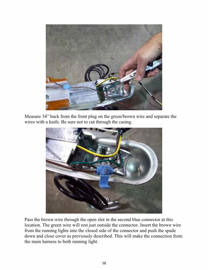
Measure 34” back from the front plug on the green/brown wire and separate the
wires with a knife. Be sure not to cut through the casing.
Pass the brown wire through the open slot in the second blue connector at this
location. The green wire will rest just outside the connector. Insert the brown wire
from the running lights into the closed side of the connector and push the spade
down and close cover as previously described. This will make the connection from
the main harness to both running light.
59
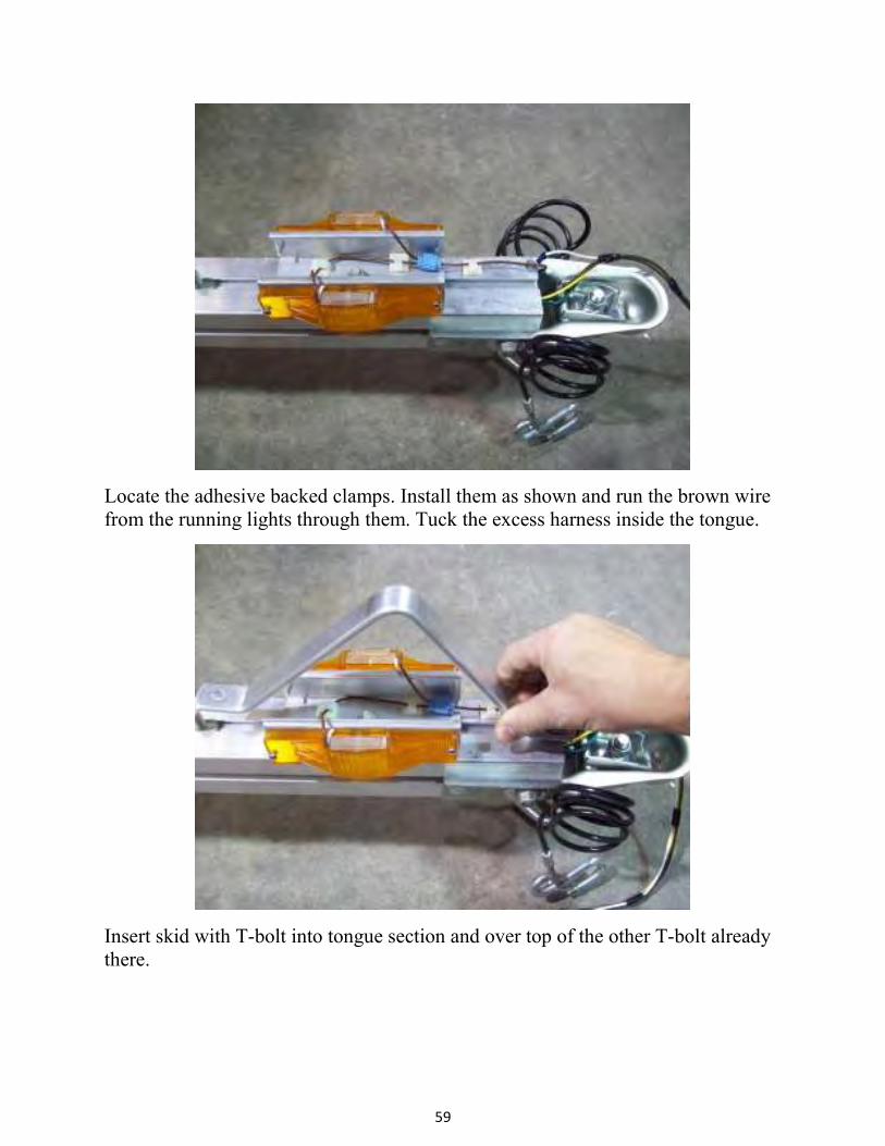
Locate the adhesive backed clamps. Install them as shown and run the brown wire
from the running lights through them. Tuck the excess harness inside the tongue.
Insert skid with T-bolt into tongue section and over top of the other T-bolt already
there.
60
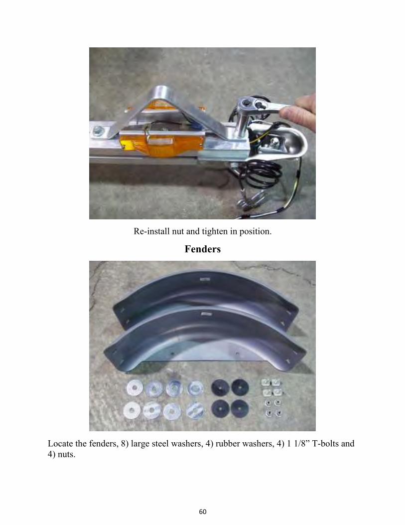
Re-install nut and tighten in position.
Fenders
Locate the fenders, 8) large steel washers, 4) rubber washers, 4) 1 1/8” T-bolts and
4) nuts.

61
Trailer shown right side up
Insert two 1 1/8” T-bolts into the side rail.
Slide the T-bolts into position over the tire and install two rubber washers and two
steel washers as shown.
Steel washers
Rubber washers

62
Install the fender, two more steel washers, and nuts, center the fender over the axle
and tighten the nuts. Repeat for the other side.
Wheels
Locate the wheels and the 8) lug nuts.
63
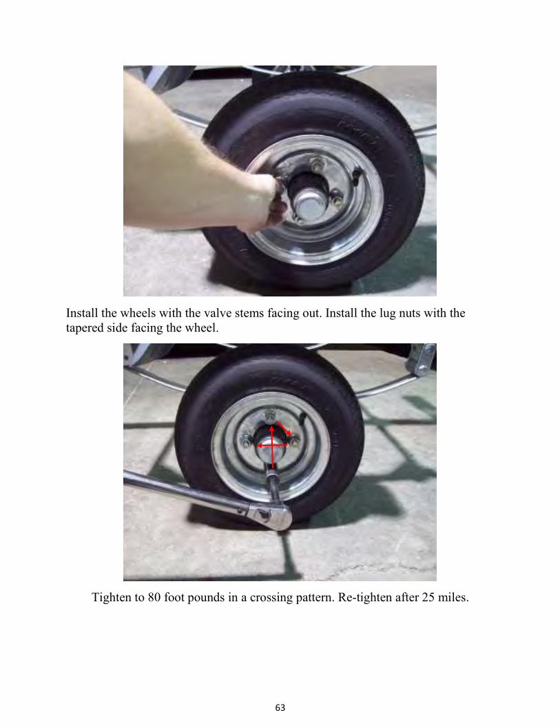
Install the wheels with the valve stems facing out. Install the lug nuts with the
tapered side facing the wheel.
Tighten to 80 foot pounds in a crossing pattern. Re-tighten after 25 miles.
64
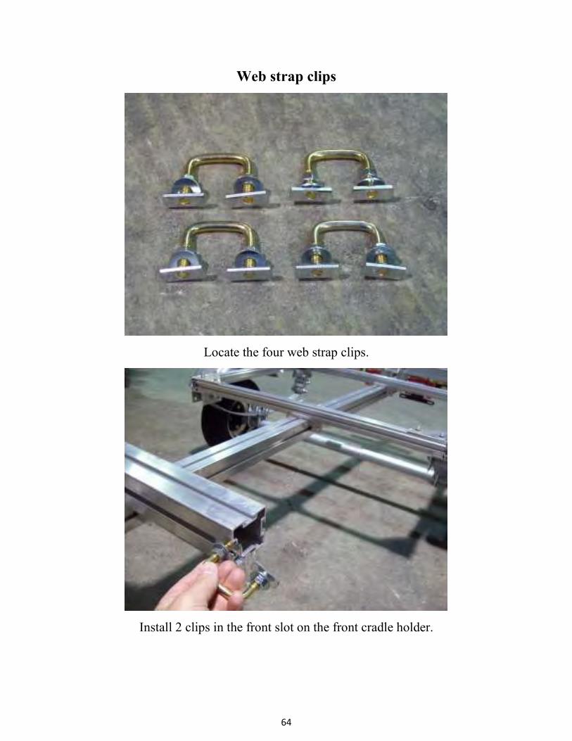
Web strap clips
Locate the four web strap clips.
Install 2 clips in the front slot on the front cradle holder.

65
Tighten the nuts. Repeat by installing 2 clips in the rear slot of the rear cradle
bracket.
Locate 5) ¾” T-bolts, 5) 3/8” flat washers, and 5) large flange nuts these are in the
same bag with the web strap clips.

66
Install two T-bolts in the top of the front cradle as shown.
Install three T-bolts in the top of the rear cradle as shown. At this point you should
refer to the Hobie instructions for installation of the cradles.
T-bolts
T-bolts

67
Finished trailer

68
KJM 05/05/14