Sustainable Energy Solutions for Irrigation and Harvesting...
67
Sustainable Energy Solutions for Irrigation and Harvesting in Developing Countries Thesis by Prakhar Mehrotra In Partial Fulfillment of the Requirements for the Degree of Aerospace Engineer California Institute of Technology Pasadena, California 2013 (Submitted May 31, 2013)
-
Upload
truongkhanh -
Category
Documents
-
view
213 -
download
0
Transcript of Sustainable Energy Solutions for Irrigation and Harvesting...

Sustainable Energy Solutions for Irrigation and
Harvesting in Developing Countries
Thesis by
Prakhar Mehrotra
In Partial Fulfillment of the Requirements
for the Degree of
Aerospace Engineer
California Institute of Technology
Pasadena, California
2013
(Submitted May 31, 2013)

ii
© 2013
Prakhar Mehrotra
All Rights Reserved

iii
For my family

iv
Acknowledgements
I would like to express my deepest appreciation for my advisor Professor Beverly
McKeon for providing the support and guidance I needed to carry out this work. Her
timely advice and constant feedback helped me to stay focused towards my goal. I am
very grateful for the opportunity that I was given to work on a challenging multidisci-
plinary problem. I am also indebted to the other members of my committee, Professor
Guruswami Ravichandran and Professor Hans Hornung, for their encouragement and
constructive criticism.
I would also like to thank my mentor and friend, Bahram Valiferdowsi, for his help
and support during my graduate studies at Caltech. He not only provided feedback
on scientific discussions but also on many other non-scientific issues which form a
crucial part of graduate student life.
I would also like to thank Professor Tom Prince and Michelle Judd from Keck
Institute of Space Studies, Caltech for providing me the opportunity to lead and
organize the Caltech Space Challenge. The knowledge and experience learned from
this study were very helpful in shaping my scientific career.
I would also like to thank Jonathan Mihaly, who as a good friend, was always will-
ing to help and give his best suggestions. Many thanks to my friends and classmates
including Michio Inoue, Nicholaus Parizale, Duvvuri Subrahmanyam, Bharat Prasad,
Piya Pal and Gerelt Tserenjigmid for making my stay at Caltech a memorable one.
I would also like to thank my parents and sister for always supporting me and
helping me realize my potential.
Finally, I would like to thank my wife, Lavanya Kona, for believing in me. Her
patience has been an immense source of inspiration for me. This thesis would have

v
not been possible without her support.
This work was carried out by funding and support from the Graduate Aerospace
Laboratories of the California Institute of Technology (GALCIT).

vi
Abstract
One of the critical problems currently being faced by agriculture industry in develop-
ing nations is the alarming rate of groundwater depletion. Irrigation accounts for over
70% of the total groundwater withdrawn everyday. Compounding this issue is the
use of polluting diesel generators to pump groundwater for irrigation. This has made
irrigation not only the biggest consumer of groundwater but also one of the major
contributors to green house gases. The aim of this thesis is to present a solution to
the energy-water nexus. To make agriculture less dependent on fossil fuels, the use
of a solar-powered Stirling engine as the power generator for on-farm energy needs is
discussed. The Stirling cycle is revisited and practical and ideal Stirling cycles are
compared. Based on agricultural needs and financial constraints faced by farmers in
developing countries, the use of a Fresnel lens as a solar-concentrator and a Beta-type
Stirling engine unit is suggested for sustainable power generation on the farms. To
reduce the groundwater consumption and to make irrigation more sustainable, the
conceptual idea of using a Stirling engine in drip irrigation is presented. To tackle the
shortage of over 37 million tonnes of cold-storage in India, the idea of cost-effective
solar-powered on-farm cold storage unit is discussed.
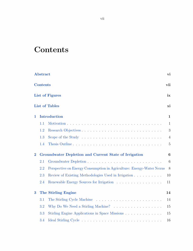
vii
Contents
Abstract vi
Contents vii
List of Figures ix
List of Tables xi
1 Introduction 1
1.1 Motivation . . . . . . . . . . . . . . . . . . . . . . . . . . . . . . . . . 1
1.2 Research Objectives . . . . . . . . . . . . . . . . . . . . . . . . . . . . 3
1.3 Scope of the Study . . . . . . . . . . . . . . . . . . . . . . . . . . . . 4
1.4 Thesis Outline . . . . . . . . . . . . . . . . . . . . . . . . . . . . . . . 5
2 Groundwater Depletion and Current State of Irrigation 6
2.1 Groundwater Depletion . . . . . . . . . . . . . . . . . . . . . . . . . . 6
2.2 Perspective on Energy Consumption in Agriculture: Energy-Water Nexus 8
2.3 Review of Existing Methodologies Used in Irrigation . . . . . . . . . . 10
2.4 Renewable Energy Sources for Irrigation . . . . . . . . . . . . . . . . 11
3 The Stirling Engine 14
3.1 The Stirling Cycle Machine . . . . . . . . . . . . . . . . . . . . . . . 14
3.2 Why Do We Need a Stirling Machine? . . . . . . . . . . . . . . . . . 15
3.3 Stirling Engine Applications in Space Missions . . . . . . . . . . . . . 15
3.4 Ideal Stirling Cycle . . . . . . . . . . . . . . . . . . . . . . . . . . . . 16
viii
3.5 Practical Stirling Cycle . . . . . . . . . . . . . . . . . . . . . . . . . . 22
3.6 Types of Stirling Engines . . . . . . . . . . . . . . . . . . . . . . . . . 25
3.7 Review of Stirling Engine Optimization . . . . . . . . . . . . . . . . . 27
4 The Stirling Engine: A Solution to Energy-Water Nexus 29
4.1 Overview . . . . . . . . . . . . . . . . . . . . . . . . . . . . . . . . . . 29
4.2 Design Objectives . . . . . . . . . . . . . . . . . . . . . . . . . . . . . 29
4.3 Design Challenges . . . . . . . . . . . . . . . . . . . . . . . . . . . . . 30
4.3.1 Stirling engine . . . . . . . . . . . . . . . . . . . . . . . . . . . 30
4.3.2 Solar concentrator . . . . . . . . . . . . . . . . . . . . . . . . 30
4.4 The Conceptual Design . . . . . . . . . . . . . . . . . . . . . . . . . . 31
4.4.1 Stirling engine selection . . . . . . . . . . . . . . . . . . . . . 31
4.4.2 Solar concentrator selection . . . . . . . . . . . . . . . . . . . 33
4.4.3 Solar receiver and heat transport system . . . . . . . . . . . . 36
4.5 Applications of Stirling Engine in Agriculture . . . . . . . . . . . . . 37
4.5.1 Drip irrigation . . . . . . . . . . . . . . . . . . . . . . . . . . . 37
4.5.2 Food harvesting: micro-cold storage . . . . . . . . . . . . . . . 39
5 Conclusion 42
5.1 Conclusion . . . . . . . . . . . . . . . . . . . . . . . . . . . . . . . . . 42
5.2 Future Work . . . . . . . . . . . . . . . . . . . . . . . . . . . . . . . . 43
References 46

ix
List of Figures
1.1 Annual water consumption for irrigation in selected countries. . . . . . 2
1.2 The percentage of net area irrigated by irrigation source in India. . . . 3
2.1 Groundwater changes in India (during 2002-2008) and Middle East (dur-
ing 2003-2009) with losses in red and gains in blue, based on GRACE
[15] satellite observations. . . . . . . . . . . . . . . . . . . . . . . . . . 7
2.2 Non-renewable energy consumption in agricultural operations in India. 8
2.3 Typical irrigation systems used in India. . . . . . . . . . . . . . . . . 10
2.4 A 1kW Microgen Stirling engine and its adaptaion for the OkoFEN-e
wood pellet boiler. . . . . . . . . . . . . . . . . . . . . . . . . . . . . . 13
3.1 The Stirling engine generators currently under development at NASA. 17
3.2 Lord Kelvin’s account of Stirling’s air engine to his natural philosphy
class [55] . . . . . . . . . . . . . . . . . . . . . . . . . . . . . . . . . . 19
3.3 Superimposed Stirling and Carnot cycles. Same values of maximum
(and minimum) pressure and volume are used. . . . . . . . . . . . . . 21
3.4 Comparision of ideal and practical Stirling cycle for same value of mean
pressure, maximum (and minimum) pressure and volume . . . . . . . . 24
3.5 Schematic of the three types of Stirling engine. . . . . . . . . . . . . . 27
4.1 Schematic of the overall design of the solar-powered Stirling system. Not
shown is the drivetrain and the support for various components. . . . . 32
4.2 The PV diagram for the three types of Strirling engine based on Schmidt
analysis. . . . . . . . . . . . . . . . . . . . . . . . . . . . . . . . . . . . 33
x
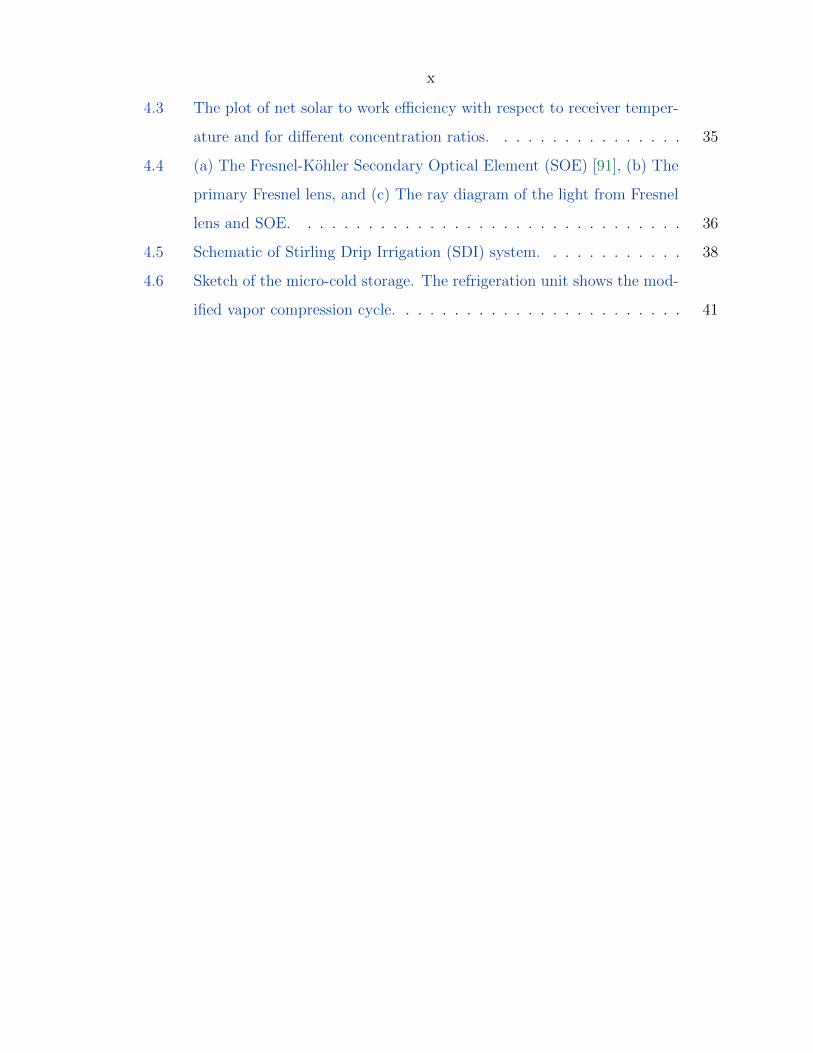
4.3 The plot of net solar to work efficiency with respect to receiver temper-
ature and for different concentration ratios. . . . . . . . . . . . . . . . 35
4.4 (a) The Fresnel-Kohler Secondary Optical Element (SOE) [91], (b) The
primary Fresnel lens, and (c) The ray diagram of the light from Fresnel
lens and SOE. . . . . . . . . . . . . . . . . . . . . . . . . . . . . . . . 36
4.5 Schematic of Stirling Drip Irrigation (SDI) system. . . . . . . . . . . . 38
4.6 Sketch of the micro-cold storage. The refrigeration unit shows the mod-
ified vapor compression cycle. . . . . . . . . . . . . . . . . . . . . . . . 41
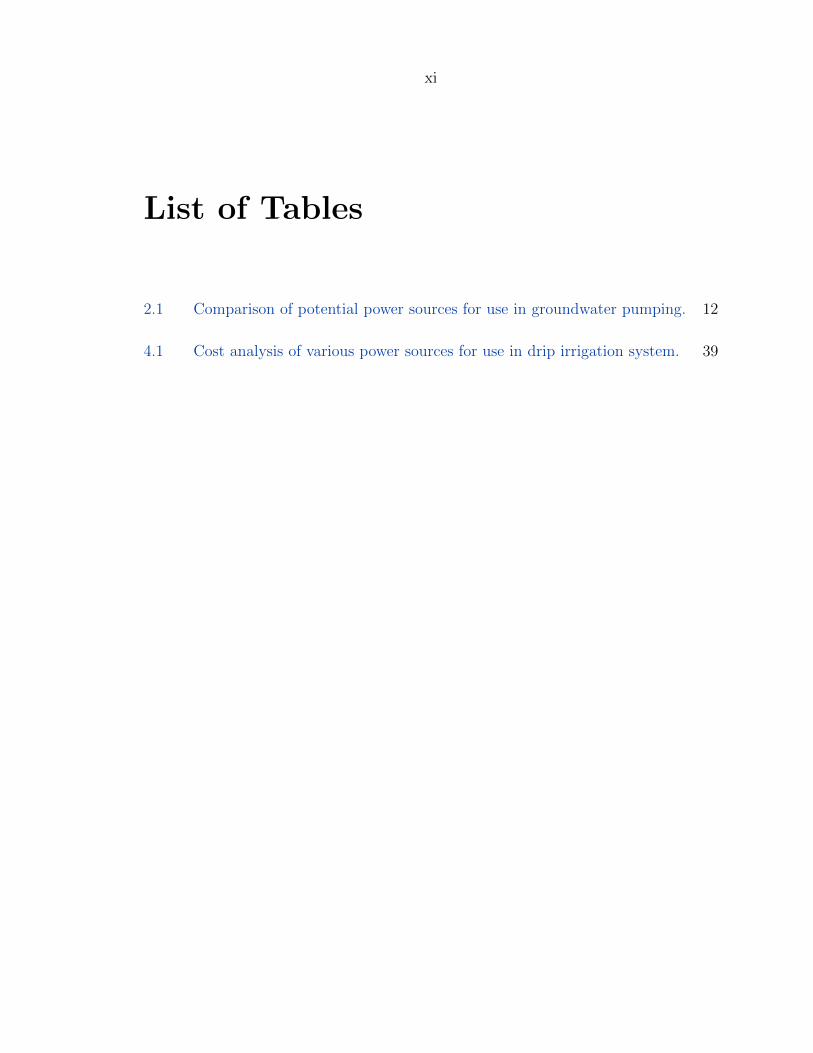
xi
List of Tables
2.1 Comparison of potential power sources for use in groundwater pumping. 12
4.1 Cost analysis of various power sources for use in drip irrigation system. 39

1
Chapter 1
Introduction
1.1 Motivation
Agriculture requires the use of fresh water to irrigate crops. On Earth, 2.5% of the
total global water is the fresh water, 68.6% of which is in form of glaciers and ice caps,
30% lies under the ground in rock fractures and soil pores, and remaining 1.4% lies
over the surface in form of rivers and lakes [1]. Groundwater forms a major source of
fresh water for agricultural uses [2–5].
India and China inhabit about 37% of the world’s population [6], but have only
9% of the world’s groundwater resources [2]. In China, groundwater is used to irrigate
more than 40% of the total arable land and to supply 70% of drinking water [7]. India
alone accounts for over 56.1% of global ground water withdrawal for irrigation every
year [8]. Figure 1.1 shows the annual water consumption for irrigation in India and
China along with other groundwater consuming countries [9].
Increasing human population and inefficient surface water irrigation system has
forced the farmers in developing countries to use groundwater as a major source for
irrigation [10–14]. Even though groundwater is considered a renewable resource [1],
its over pumping for irrigation needs has caused it to deplete at a rate which is much
higher than the rate at which it could be replenished. In the densely populated regions
of India, China and South East Asia, the farmers are now facing an imminent threat
due to the receding groundwater levels [12, 15, 16].
In developing countries, the energy to pump the groundwater primarily comes

2
India China USA Saudi Arabia Australia0
500
1000
1500
2000
2500
3000
3500
Annual W
ate
r C
onsu
mpti
on f
or
Irri
gati
on (
km3/y
r)Groundwater
Surface water
Figure 1.1: Annual water consumption for irrigation in selected countries.Source: IGRAC GGIS
by operating a water pump [5, 11–13, 17]. Figure 1.2 shows the changing landscape
of the sources of irrigation in India. In 2010, over 60% of the net irrigated area in
India was irrigated by groundwater which was pumped by using electric and diesel
pumps [8]. Since the electricity generation in developing countries primarily comes
from burning fossil fuels (e.g.: coal) [18], it is safe to conclude that pumping the
groundwater contributes to green house emissions. Both fossil fuel power plants and
diesel generator exhausts contains high amounts of green house gases [18, 19]. Several
on-farm studies done by Shah et al. and United Nations Water have concluded that
groundwater irrigation is the most energy consuming operation on the farm. [4, 11–
13, 17, 20].

3
1970 1975 1980 1985 1990 1995 2000 2005 2010Year
0
20
40
60
80
100
% S
hare
of
Net
Are
a Irr
igate
d (
%)
Electric and Diesel Pumps
Canals
Figure 1.2: The percentage of net area irrigated by irrigation source in India.Source: CMIE
1.2 Research Objectives
The objective of this thesis is to propose one of the solution which would make
groundwater pumping sustainable and help reduce the groundwater consumption.
Specifically, this thesis discusses the feasibility of using solar energy to operate water
pumps by way of using a Stirling generator. It provides the design elements for a solar-
powered Stirling generator and discuss its applications for two on-farm operations:
(a) as a water pump for usage in drip irrigation system (b) as a generator to drive
the compressor in a portable cold-storage system. The drip irrigation technology
has been in existence since 1920 and is one of the efficient ways to limit the water
consumption in irrigation [21–23].
This thesis is also intended to provide a review of Stirling engine and the associated

4
design challenges. The discussion aims to provide the current state-of-art in Stirling
engine technology and can be loosely used as a guideline for a conceptual design of
a system which wishes to use Stirling engine as one of its component. The Stirling
engine, by way of its design, can convert thermal energy into mechanical energy and
hence its application is not limited to use of solar energy but also other renewable
energy sources like bio-diesel, rice pellets etc.
1.3 Scope of the Study
As mentioned earlier that the goal of this thesis is to discuss the idea of using a solar-
powered Stirling water pump as a way to pump groundwater sustainably. While
the goal seems simple to state, this thesis can be extremely wide if the scope is not
limited. The reason for this is because both Stirling engine design and harnessing
renewable energy are two separate problems and are topics of active research. The
characteristics of each could result in numerous permutations each solving the issue
of groundwater pumping. For example, one could use photovoltaic to harness solar
energy and use it directly to operate a water pump. Alternatively, in areas with
high wind potential, wind turbines could be used to generate electricity to operate
a water pump. The solutions presented in this thesis are aimed towards developing
countries like India and China, both of which have a high solar insolation justifying
the use of solar energy. The case for the use of Stirling generator over photovoltaic
is discussed in Chapter 2. It is not obvious a priori to favor the use of photovoltaic
over Stirling generator as a way to convert solar energy into electrical energy for
the on-farm applications. While photovoltaics have been successfully used in deserts
(e.g.: Solar power plants in Mojave Desert) and in urban areas (e.g.: roof-top of the
buildings), Stirling engines have found applications as a power module for submarines
(e.g.: Gotland-class submarine with Stirling air-independent propulsion) and are topic
of active research at NASA for a possible power source for the next lunar habitat.
The issue of rapid groundwater depletion is also extremely wide. While UN has
regarded access to safe drinking water as a human right [24], it remains unclear on
5
its stand over the issue of access to the groundwater. There have been numerous
studies which suggest guidelines to regulate groundwater usage [25–27], the issue of
groundwater depletion in this thesis is discussed from a technological point of view.
The idea of using a solar-powered Stirling engine with the efficient drip irrigation
system is discussed.
1.4 Thesis Outline
This thesis is divided into five chapters. The description of each is as follows:
Chapter 1 In this chapter, the underlying issues that serve as a motivation for this
thesis are presented. The research objectives and the scope of the current study
are also explained.
Chapter 2 This chapter presents a brief overview on groundwater depletion and the
energy-water nexus. This chapter also provides a review of existing methodolo-
gies used by farmers in developing countries, and provides a justification for the
use of solar power and Stirling engine as a way to operate water pumps.
Chapter 3 This chapter presents the overview on Stirling cycle, the associated the-
ory, real-world considerations and current state-of-art in Stirling technology.
The discussions in this chapter serve as guidelines for various engineering deci-
sions made for the proposed solar-powered Stirling generator.
Chapter 4 In this chapter the conceptual design of the solar-powered Stirling gener-
ator is described. The rationale for choosing a beta-type Stirling engine, fresnel
lens as solar concentrator and molten alkali metals for thermal storage is pre-
sented. It also describes the use of a Stirling engine in conjunction with drip
irrigation and to power a compressor for an on-farm cold storage unit.
Chapter 5 In this chapter, the summary of all findings is reported. The outlook for
future directions in this research area is also provided.
6
Chapter 2
Groundwater Depletion andCurrent State of Irrigation
2.1 Groundwater Depletion
Look, water has been a resource that has been plentiful. But now weve got climate
change, weve got population growth, weve got widespread groundwater contamination,
weve got satellites showing us we are depleting some of this stuff. I think weve taken
it for granted, and we are probably not able to do that any more . ( Dr. James S.
Famiglietti in an interview to New York Times [28])
The above quote succinctly describes the essence of the problem. Groundwater is
the predominant source of irrigation around the world, especially in India (39 million
ha), China (19 million ha) and USA (17 million ha) [10]. To give a perspective on
water usage in the agriculture: producing 1 pound of grain requires about 200 gallons
of fresh water while our power plants consume on an average of 143 billion gallons of
fresh water every day to produce energy. As the population is increasing, so is the
demand of food, energy and hence fresh water. The importance of groundwater to
irrigation is similar to that of gasoline for driving automobiles, both must be replen-
ished or refilled from time to time. However, recent measurements of groundwater
levels by the NASA’s Gravity Recovery and Climate Experiment (GRACE) show that
many states in northern India have been losing water at a mean rate of 4.0± 1.0 cm
yr−1 equivalent height of water (17.7 ± 4.5 km3 yr−1) [15, 16]. Figure 2.1 shows a
7
plot from the GRACE mission showing groundwater depletion in parts of India and
Middle East.
(a) India (b) Middle East
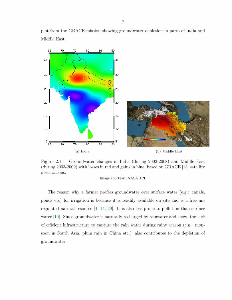
Figure 2.1: Groundwater changes in India (during 2002-2008) and Middle East(during 2003-2009) with losses in red and gains in blue, based on GRACE [15] satelliteobservations.
Image courtesy: NASA JPL
The reason why a farmer prefers groundwater over surface water (e.g.: canals,
ponds etc) for irrigation is because it is readily available on site and is a free un-
regulated natural resource [4, 14, 29]. It is also less prone to pollution than surface
water [10]. Since groundwater is naturally recharged by rainwater and snow, the lack
of efficient infrastructure to capture the rain water during rainy season (e.g.: mon-
soon in South Asia, plum rain in China etc.) also contributes to the depletion of
groundwater.

8
2.2 Perspective on Energy Consumption in Agri-
culture: Energy-Water Nexus
One of the key challenges faced by India and China is that of making irrigation
less dependent on energy and to invest in technologies which lead to efficient use
of groundwater in irrigation. Figure 2.2 shows the growth in non-renewable energy
consumption by agriculture over the last three decades.
1980 1985 1990 1995 2000 2005 2010Year
0
20000
40000
60000
80000
100000
120000
140000
Energ
y C
onsu
mpti
on b
y A
gri
cult
ure
(G
wh)
Figure 2.2: Non-renewable energy consumption in agricultural operations in India.Source: CMIE
The most recent data published by the Centre for Monitoring Indian Economy
(CMIE) [8] on agriculture and irrigation estimates about 8.0 million electric powered
water pumps and about 5.0 million water pumps running on diesel to irrigate 54,500
hectares of land in India. A typical electric powered water pumping system uses a

9
10 hp horsepower submersible or turbine pump to pull water from about 350 ft with
a flow rate of 75 gpm at 75% pump efficiency running for about 6 hours a day [13].
Back of the envelope calculations using these numbers estimate about 350 Gw-hr
electricity consumption per day. That is enough electricity to power 30,000 homes in
US for one year.
Similarly, a typical farmer in northern India runs a 4 hp diesel powered water
pump for about 8 hours to pull water from 150 ft with a flow rate of 75 gpm at
75% pump efficiency [13]. A typical diesel engines used for irrigation purposes in
India is about 20% efficient [13, 14] and since gallon of diesel is capable of providing
54.5 hp-hr of energy [30], a farmer is consuming approximately 3 gallons of diesel
per day!. Thus, the CO2 emissions from running diesel engine for irrigation alone
is about 54.5 millions of metric tonnes of carbon dioxide (MMtCO2e) per year or
0.2% of the global CO2 emissions per year. Thus, irrigation is not only the biggest
consumer of groundwater but also one of the major contributor to the Green House
Gases (GHG). Adding the GHG contribution of irrigation with industry emissions
explains why India and China are one of the most polluted countries in the world.
The above calculations highlight a crucial link between groundwater and energy.
At the micro level, the two are interdependent, but at the macro level they could be
thought of as two independent problems. Reduction in groundwater depletion would
lead to healthier acquifer system and a reduction in sea-level rise, which would help
the climate. The excess groundwater doesn’t seep back into the ground, instead it
evaporates and finally enters the ocean thereby causing rise in global sea-level [31].
The issue of groundwater depletion needs to be tackled at policy level and by promot-
ing micro and drip irrigation techniques. However, the issue of energy consumption
in irrigation needs to be addressed by building renewable energy solutions [32]. This
will take off the load from the electricity grid as well reduce contribution of green
house gases.
10
2.3 Review of Existing Methodologies Used in Ir-
rigation
Before the green revolution, the canal system was the major source of irrigation in
India and China. The flood flows in the major rivers like Ganges, Indus and Yangtze
were diverted through inundation canals for irrigation. In the areas where rivers
were scarce, water was stored in large tanks for use in agriculture. A farmer would
flood his field so as to ensure sufficient supply of water to the crops and to safeguard
himself from erratic canal water supplies. However, with advent of green revolution
and to meet the ever growing demands for food, groundwater usage started to gain
momentum. Over the three decades, the net area irrigated by canal system in India
dropped by 18%.
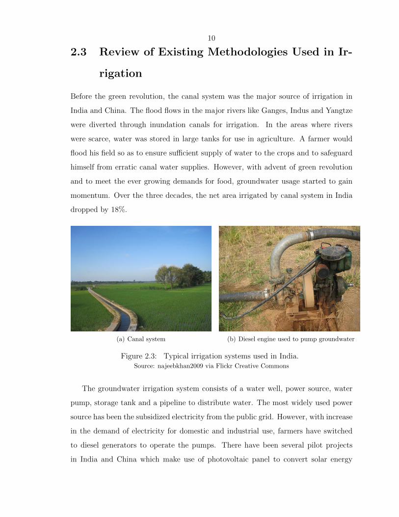
(a) Canal system (b) Diesel engine used to pump groundwater
Figure 2.3: Typical irrigation systems used in India.Source: najeebkhan2009 via Flickr Creative Commons
The groundwater irrigation system consists of a water well, power source, water
pump, storage tank and a pipeline to distribute water. The most widely used power
source has been the subsidized electricity from the public grid. However, with increase
in the demand of electricity for domestic and industrial use, farmers have switched
to diesel generators to operate the pumps. There have been several pilot projects
in India and China which make use of photovoltaic panel to convert solar energy

11
into electricity used to operate the pump. However, no large scale projects, utilizing
renewable energy as power source, have been deployed both in India and China. One
of the main reasons being lack of willingness by the farmer to use any new technology.
2.4 Renewable Energy Sources for Irrigation
The two promising renewable energy sources which could be used for on-farm appli-
cation are solar and wind energy. The other possibility could be the use of biofuels
instead of diesel in existing generators. However, the production of biofuels require
huge amounts of fresh water that may compete directly with food crop production
[33]. Table 2.4 summarizes the pros and cons of different power sources for use with
groundwater pump.
Since India and China are both located in sun-belt of the Earth [35], its use is
preferred over wind and biodiesel as a energy source to power the pump. Within solar,
a photovoltaic system enjoys the benefit of lower initial cost when compared with
solar-powered Stirling engine. However, its major disadvantage is the system security
requirements. The PV array, which are the most expensive components, need to be
saved from theft, vandalism and livestock. Sovacool et al. have reported vandalism
as the major social barrier to the success of photovoltaic system in rural and on-farm
areas [36, 37]. Stirling engine, on the other hand, are immune to vandalism as they
are enclosed in a solid metal casing (see fig 2.4) like any other engine. However, when
using solar power to operate Stirling engine, the use of plastic Fresnel lens is preferred
over parabolic mirrors due to their lower cost and higher resistance to breaking [38].
Figure 2.4 shows a 1kW Stirling engine developed by Microgen which could be used
to convert heat energy from wood pellet boiler into electricity [39, 40]. This system
could be used on-farm and wood can be replaced by livestock waste as a fuel for the
engine.

12
PowerSource
Pros Cons
Generator
1. Cheapest 1. Expensive fuel2. Easy to install and operate 2. Short life expectancy
3. Require frequent maintenance4. Polluting (when using diesel)
Wind Turbine
1. Cheaper when compared tophotovoltaic [34]
1. Very high maintenance costs
2. No fuel required 2. Effective only in high wind ar-eas
3. Clean 3. Lower performance in low tomoderate wind conditions4. Skilled labor required to install
Photovoltaic
1. Moderate initial cost 1. Low maintenance require-ments
2. No fuel required 2. High safety requirements fromtheft and vandalism
3. Clean 3. Investment required to expandto match the power needs4. Low performance on cloudyday
Stirling Engine
1. Higher thermal efficiency whencompared to photovoltaic
1. High initial cost
2. Can operate on variety of fuelsincluding solar.
2. Require frequent maintenance
3. No threat from theft or van-dalism4. Require little investment toexpand to higher power require-ments5. No risk of explosion when com-pared to diesel generator6. Clean
Table 2.1: Comparison of potential power sources for use in groundwater pumping.

13
(a) Stirling engine (b) Stirling engine as used with pellet boiler
Figure 2.4: A 1kW Microgen Stirling engine and its adaptaion for the OkoFEN-ewood pellet boiler.
Image courtesy: OkoFEN-e
14
Chapter 3
The Stirling Engine
3.1 The Stirling Cycle Machine
These imperfections have been in a great measure removed by time and especially by
the genius of the distinguished Bessemer. If Bessemer iron or steel had been known
thirty five or forty years ago there is a scarce doubt that the air engine would have
been a great success. It remains for some skilled and ambitious mechanist in a future
age to repeat it under more favorable circumstances and with complete success. ( Dr.
Robert Stirling, 1876)
The Stirling cycle machine was invented in 1816 by a Scottish clergymen Revd
Dr. Robert Stirling [41]. It is a unique device in the sense that it’s theoretical
efficiency is equal to that of a Carnot cycle machine [42]. The main motivations
for Robert Stirling to build this machine were to pump water from a quarry and
that he wanted to build an engine which operated at lower working pressure than
existing Watt’s steam engines. However, the understanding of the theoretical basis of
Stirling cycle required the geniuses of Sadi Carnot, William Thomson (Lord Kelvin)
and McQuorne Rankine. The Stirling cycle is a closed regenerative thermodynamic
cycle where the conversion of heat to work (or vice versa) takes place due to cyclic
compression and expansion of the working fluid [42–44]. Unlike the Diesel or Otto
cycle, the Stirling cycle has a fixed-mass of working fluid constrained in a volume
and the flow is controlled by the internal volume changes. Since there is no need to
exhaust or vent the working fluid, a prime mover operating on a Stirling cycle does
15
not require any valves and is a clean engine with no pollution.
The machines operating on the Stirling cycle gained widespread popularity in
1820-1830, mainly because they were safe to operate owing to low working pressures
and required less skilled labour. However, the invention of the internal combustion
engine in mid 18th century, the arrival of the electric motor and a lack of high tem-
perature materials led to a rapid decline in use of Stirling machines. While there is
very little doubt about the technical and economic superiority of an internal combus-
tion engine running on gasoline, the requirements of the 21st century dictate the use
of machines which run on renewable energy sources and are less polluting [45]. The
solution may lie with Stirling cycle machines. The size, energy density and economic
constrain may not favor the replacement of internal combustion engines in automo-
biles with these machines, but they definitely offer a good promise as a replacement
for other uses of internal combustion engines like that of pumping water or as mobile
power stations [42, 45, 46].
3.2 Why Do We Need a Stirling Machine?
Some reasons why we need a Stirling machine in 21st century is its non-polluting
nature, ability to use any heat source (e.g. solar radiation, biogas, natural gas etc),
high thermal efficiency (equal to Carnot efficiency), quieter operation, longer life (the
Stirling engine has no valves or fuel injection systems) and its good performance at
part loads [47].
3.3 Stirling Engine Applications in Space Missions
There has been renewed interest in utilizing nuclear powered Stirling engines to gener-
ate power for future NASA missions. In the past, NASA missions (e.g. MSL-Curiosity,
Cassini, Voyager 1, Voyager 2, Apollo Missions) have been using Radioisotope Ther-
moelectric Generators (RTGs) to power missions for which solar power is not viable.
The other power systems like photovoltaics (e.g. Dawn, Juno) and battery systems

16
(e.g. Hubble Space Telescope) are feasible for shorter missions where the power re-
quirements are lower [48]. The advantage of nuclear power is that they require lesser
packing mass, lesser deployed area [48], and can provide almost limitless power for
almost any duration [49]. However, the existing RTGs are efficient only for continuous
power supply of upto 5kW [50]. Hence, NASA and Department of Energy (DOE) are
pursuing a dynamic system which uses nuclear fission to generate power. One such
system called Advanced Stirling Radioisotope Generator (ASRG) is currently being
developed by the Lockheed Martin Space Systems, under contract from DOE [51, 52].
For a given mass of nuclear fuel (PuO2), the Stirling cycle has a higher thermal ef-
ficiency when compared to the RTGs and offers a four-fold reduction in nuclear fuel
[51]. NASA has recently expanded the ASRG program and has given the contract to
Sunpower Inc. to build a Advanced Stirling Convertor (ASC) under the guidance of
NASA Glenn Research Center (GRC) [51, 53]. ASC uses a free-piston Stirling engine
and a linear alternator to generate a specific power from 3 kW/kg to 7 kW/kg [51].
Figure 3.1 shows the ASRG and ASC units.
There have been several other studies on using a dynamical power system, such
as Brayton and Stirling cycle for future robotic pre-cursor, resource utilization and
manned missions [48, 54].
3.4 Ideal Stirling Cycle
On the principle of the motive power of heat Stirling’s Air Engine is constructed. It
is very simple. One mass of air alone is necessary to drive it. Here we have a large
cylinder with a plunger in it. Suppose it to be at the top. There is a considerable
quantity of air below. If we apply the spirit lamp below and heat the air it expands
and rushes up along the sides of the plunger, along the tube and forces up the piston
in the other small cylinder. There is a wheel placed between the two cylinders. There
is a crank attached to each end of the axle of the wheel. When the small piston rises
it turns round the wheel which brings the plunger down and this drives out most of the
heated air. The air in coming in contact with the cool metal at the top contracts and

17
(a) ASC model (b) ASRG-EU undergoing launch vibration test
Figure 3.1: The Stirling engine generators currently under development at NASA.Image courtesy: NASA [51, 53]
draws down the piston which raises the plunger and again the air is heated and so on.
In order to condense the air better it is expedient to have a stream of water rushing
over the upper part thus carrying away the heat. (Lord Kelvin in 1850 explaining the
Stirling’s air engine to his natural philosophy class[55])
The above lecture by William Thomson (Lord Kelvin) is probably one of the
earliest description of working of a real world Stirling engine. However, the processes
occurring inside the engine (e.g. heat transfer from spirit lamp to the air inside the
chamber) are complex and, from a theoretical standpoint, hard to explain through
18
compact set of equations or formulas. Hence, for a better understanding of a real
world Stirling machine, be it a prime mover or a refrigerator, we need to study them
by making suitable assumptions (e.g. infinite rate of heat transfer between spirit
lamp and the air inside the chamber). A thermodynamic cycle can be defined as a
closed loop cycle made up of multiple processes in a way that at every process one
of the properties of working fluid is held constant. The other important assumption
made in study of thermodynamic cycle is that of thermodynamic equilibrium or local
reversibility i.e. all the processes which the working fluid undergoes are reversible
and that there is no friction. In that sense they are ideal. The efficiency of an ideal
thermodynamic cycle gives an upper limit on the maximum efficiency which the real
world cycle can achieve.
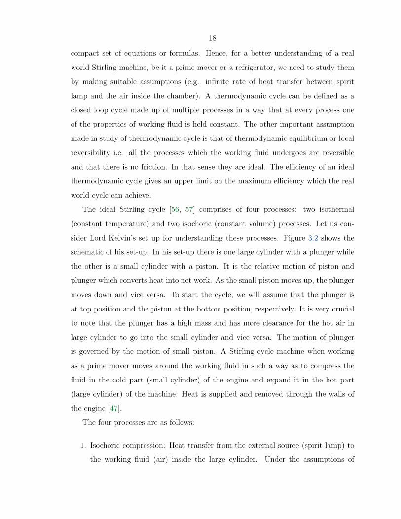
The ideal Stirling cycle [56, 57] comprises of four processes: two isothermal
(constant temperature) and two isochoric (constant volume) processes. Let us con-
sider Lord Kelvin’s set up for understanding these processes. Figure 3.2 shows the
schematic of his set-up. In his set-up there is one large cylinder with a plunger while
the other is a small cylinder with a piston. It is the relative motion of piston and
plunger which converts heat into net work. As the small piston moves up, the plunger
moves down and vice versa. To start the cycle, we will assume that the plunger is
at top position and the piston at the bottom position, respectively. It is very crucial
to note that the plunger has a high mass and has more clearance for the hot air in
large cylinder to go into the small cylinder and vice versa. The motion of plunger
is governed by the motion of small piston. A Stirling cycle machine when working
as a prime mover moves around the working fluid in such a way as to compress the
fluid in the cold part (small cylinder) of the engine and expand it in the hot part
(large cylinder) of the machine. Heat is supplied and removed through the walls of
the engine [47].
The four processes are as follows:
1. Isochoric compression: Heat transfer from the external source (spirit lamp) to
the working fluid (air) inside the large cylinder. Under the assumptions of

19
Heat from spirit lamp
Cold metal
Plunger
Piston
Wheel
Figure 3.2: Lord Kelvin’s account of Stirling’s air engine to his natural philosphyclass [55]
infinite heat transfer, this process is isochoric, as neither the plunger nor the
piston moves. The hot air instantaneously rises along the the plunger sides,
through the tube and starts to enter the small cylinder. All of these processes
happen instantaneously. It is called compression because heat is being supplied
at infinite rate such that there is no movement of either the plunger or the piston
and hence the isochoric. The temperature of working fluid becomes equal to
the external source temperature Th.
2. Isothermal expansion: Heat transfer from the working fluid to move the small
piston. This is the work stroke. The heated air enters the cold part i.e the small
cylinder and pushes the piston upwards which rotates the wheel. As a result,
the plunger in the large cylinder comes down. The process is called ’expansion’
20
because the heated air expands in the hot part of the engine i.e. the large
cylinder, and is called isothermal because the temperature of the working fluid
remains at constant at Th. The reason being the infinite rate of heat transfer
assumption and the high clearance between the plunger and the walls allowing
a medium for heat to flow.
3. Isochoric expansion: Heat transfer from the working fluid to the external sink
(cool metal). Once again, under the assumptions of infinite heat transfer, this
process is isochoric. When the piston is at the top position, the external sink
rapidly cools the working fluid in small cylinder. The plunger at this moment
is still at the bottom most position. The temperature of working fluid becomes
equal to the external sink temperature Tc.
4. Isothermal compression: Transfer of working fluid from the small cylinder into
the large cylinder. The momentum of the wheel brings down the piston thereby
flushing the cold air into the large cylinder. The plunger moves up, the air
gets again heated and the cycle repeats. It is called compression because the
piston compresses the gas in the cold part i.e. the small cylinder, and isothermal
because of infinite rate of cooling by the sink. The air remains at the minimum
temperature Tc.
Since the heat acceptance and rejection processes happen at constant temperature
Th and Tc respectively, the thermal efficiency of the ideal Stirling cycle is same as
that of ideal Carnot efficiency i.e.
η = 1− TcTh
.
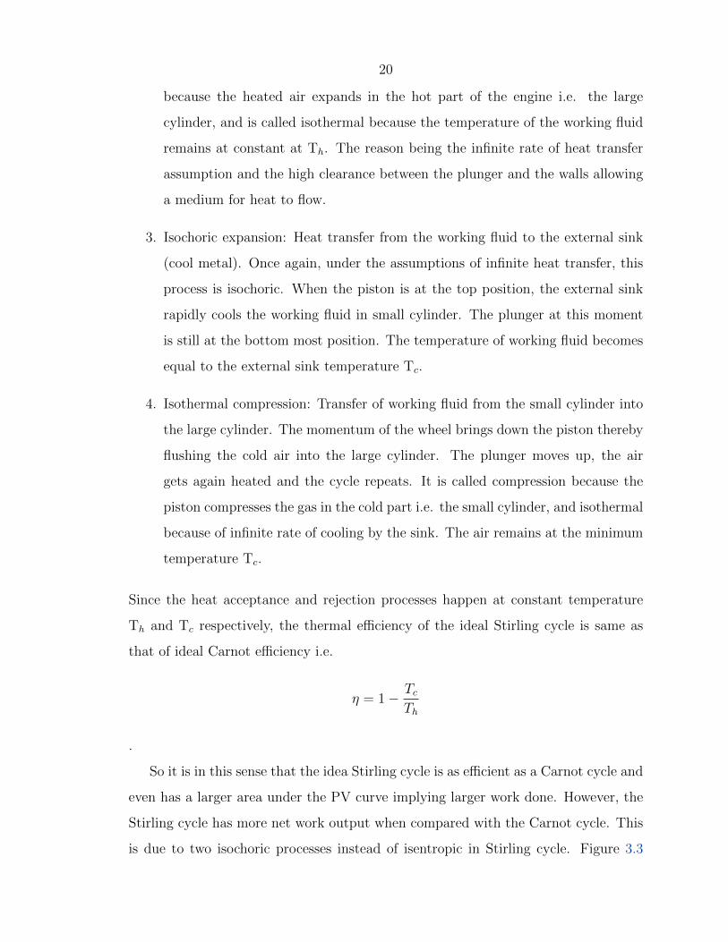
So it is in this sense that the idea Stirling cycle is as efficient as a Carnot cycle and
even has a larger area under the PV curve implying larger work done. However, the
Stirling cycle has more net work output when compared with the Carnot cycle. This
is due to two isochoric processes instead of isentropic in Stirling cycle. Figure 3.3
21
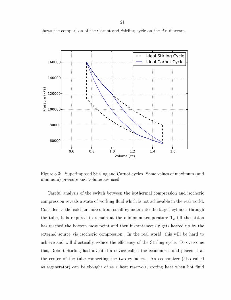
shows the comparison of the Carnot and Stirling cycle on the PV diagram.
0.6 0.8 1.0 1.2 1.4 1.6Volume (cc)
60000
80000
100000
120000
140000
160000
Pre
ssure
(kP
a)
Ideal Stirling CycleIdeal Carnot Cycle
Figure 3.3: Superimposed Stirling and Carnot cycles. Same values of maximum (andminimum) pressure and volume are used.
Careful analysis of the switch between the isothermal compression and isochoric
compression reveals a state of working fluid which is not achievable in the real world.
Consider as the cold air moves from small cylinder into the larger cylinder through
the tube, it is required to remain at the minimum temperature Tc till the piston
has reached the bottom most point and then instantaneously gets heated up by the
external source via isochoric compression. In the real world, this will be hard to
achieve and will drastically reduce the efficiency of the Stirling cycle. To overcome
this, Robert Stirling had invented a device called the economizer and placed it at
the center of the tube connecting the two cylinders. An economizer (also called
as regenerator) can be thought of as a heat reservoir, storing heat when hot fluid

22
passes through it and releasing heat to the cold fluid in next cycle. This, in our
above example, would preheat the cold air when it is entering the big cylinder during
isothermal compression. This led to a dramatic improvement in the efficiency of the
real world Stirling engine.
3.5 Practical Stirling Cycle
The real world efficiency of a Stirling cycle machine is much lower than that estimated
by the ideal thermodynamic analysis [42, 43]. This is due to the following reasons:
1. Dead volume within the engine: Since a Stirling engine works on a closed cycle,
the mass of the working fluid directly contributes to the net work output. In the
ideal cycle, it is assumed that all of the working fluid gets heated and contributes
to the power stroke. This is however not correct as some of the working fluid
is trapped within the dead volume in both the cylinders. The dead volume
is the sum of all the volumes within the working chamber which is not swept
by the pistons. Major contributors to the dead volume are the clearances,
internal volume of associated ducts and ports and the volume occupied by the
economizer [42]. Recent studies conclude that in a real Stirling engine, the dead
volume can contribute upto 50% of the total volume and account for a major
reduction in the power output [58–60]. The power reduction is proportional
to the ratio of dead volume to maximum gas volume [47]. While the dead
volume cannot be completely eliminated in any real engine, its effect on the
Stirling engine performance is adverse [61] because of the volume of gases that
get trapped in the economizer. Isothermal analysis done by considering linear
and sinusoidal variations of dead volumes within the economizer conclude that
the dead volume strongly amplifies the imperfect regeneration thereby effecting
the engine efficiency [62].
2. Departure from isothermal assumption: One of the major departures from ide-
ality is the assumption of infinite rate of heat transfer to and from the working

23
fluid by external source and sink, respectively. Several authors have concluded
that for reasonable speed of the engine (approx. 1000 rpm), these processes are
more adiabatic (no heat transfer) rather than isothermal (infinite heat trans-
fer) [42, 44]. To make the actual processes closer to isothermal, a heater and
a cooler are placed near the large cylinder and the small cylinder, respectively
[42]. The objective of these is to assist in rapid heating and cooling during the
isothermal expansion and compression phase. But this contributes to the dead
volume which in turns effects the engine performance [42, 44, 61].
3. Flow losses and heat transfer through the economizer: The main function of
the economizer (or regenerators) in a Stirling machine is to provide a thermal
reservoir to the working fluid. A perfect economizer assumes no viscous losses
and infinite heat transfer to the working fluid, which in reality, is impossible
to achieve. A well-designed economizer provides sufficient thermal contact to
the fluid and minimizes the viscous losses [63]. The sinusoidal piston motion
inside the cylinder [61] causes the working fluid to be cyclically distributed
in time-variant manner inside the total volume, hence the total mass of the
working fluid contributing towards the power stroke is reduced when compared
with the ideal cycle. The periodic distribution of the fluid causes the Reynolds
number for the flow through the economizer to oscillate. The Nusselt number,
heat transfer coefficient and the friction factor are all reported to be higher for
oscillating flow when compared to unidirectional flow through the economizer
[64, 65]. While high heat transfer coefficient is favorable, the high friction factor
contributes to the viscous flow losses.
4. Discontinuous motion of the pistons: In an ideal Stirling cycle, the piston mo-
tions are discontinuous. This is because we assume that the heat transfer to
and from the working fluid occur at constant volume (via isochoric compression
and expansion). However, in a practical Stirling engine, the piston never stops
at the end points due to inertia in the flywheel. This leads to a smooth con-
tinuous PV diagram diagram within a lesser area under the curve available to

24
overcome the mechanical and friction losses and provide positive power to the
engine. The smooth motion is also a consequence of the dead volume within
the engine. Figure 3.4 shows the comparison between ideal and practical cycle
piston motion on the PV diagram. One of the critical parameters for the effi-
cient performance of practical Stirling engine is the instantaneous phase angle
between the two pistons [61].
0.6 0.8 1.0 1.2 1.4 1.6Volume (cc)
60000
80000
100000
120000
140000
160000
Pre
ssure
(kP
a)
Ideal Stirling CycleReal Stirling Cycle
Figure 3.4: Comparision of ideal and practical Stirling cycle for same value of meanpressure, maximum (and minimum) pressure and volume
The dead volume, the continuous motion of the pistons, the limited heat transfer
to and from the working fluids, and viscous losses through the economizer contribute
to the reduction of the theoretical Stirling efficiency by about 30-35% [42]. The other
reason which limited the use of the Stirling engine was the high thermal stresses which
the engine material has to go through. Historically, this constituted a considerable

25
design challenge, as well as placed an upper limit on the maximum temperature at
which the engine can operate. While this was also the challenge for other engines
in that era (e.g. gas turbine engines), the high energy density of liquid fuels when
compared to any external combustion sources (e.g. burning of wood, solar radiation)
favored internal combustion and turbine engines over Stirling engines.
However, recent advances in material sciences [66–68] and the need for cleaner
engines have increased the interest in Stirling engines [69–71]. Recent Stirling engines
have been built for brake power varying from few watts to a megawatt, with the power
density comparable to diesel engines.
3.6 Types of Stirling Engines
A wide variety of Stirling engines have been manufactured mostly by Siemens, Phillips
and General Motors [42, 72, 73]. Any Stirling engine will have the following compo-
nents:
1. External heat source: Since the combustion takes place outside the engine, a
provision must be made for an external heat source and a mechanism for heat
transfer from the heat source to the working fluid. Usually, a solid metal with
high thermal conductivity is used to transfer the heat from the source to the
working fluid [47]. The transfer of heat is primarily by thermal conduction
from the metal to the working fluid hence the fluid must also have high thermal
conductivity. Hydrogen, helium and air are some prime candidates for the choice
of working fluids.
2. Expansion and compression region: As mentioned earlier, the Stirling engine
expands the heated gases and compresses the cold part of the gas by using the
momentum of the flywheel. Hence, a Stirling engine should have an expansion
region (usually large) which allows the heated gas to expand and pass into
the compression region (usually small) and move the piston [42, 47]. The two
regions can be part of single chamber, as in case of the Beta type of Stirling
26
engine. A provision needs to be made for the cyclic motion of working fluid
between these two regions. This is accomplished by having a displacer or a
plunger with high clearances in the expansion region for working fluid to flow
to and from the expansion and compression regions, respectively.
3. Economizer (or Regenerator): An economizer needs to be placed somewhere in
the path of the working fluid for it to exchange heat. The role of the economizer
is to store the heat when hot fluid is expanding into the compression chamber
and transfer it back to the fluid (to preheat it) when it is returning back after
compression into the expansion chamber. The design and effective placement
of economizer is crucial to the performance of Stirling engine as the former
contributes to the dead volume which adversely effects the power output from
the engine.
4. External heat sink: Like all engines, the Stirling engines also need to reject the
heat to an external sink. Usually running water is used as a heat sink.
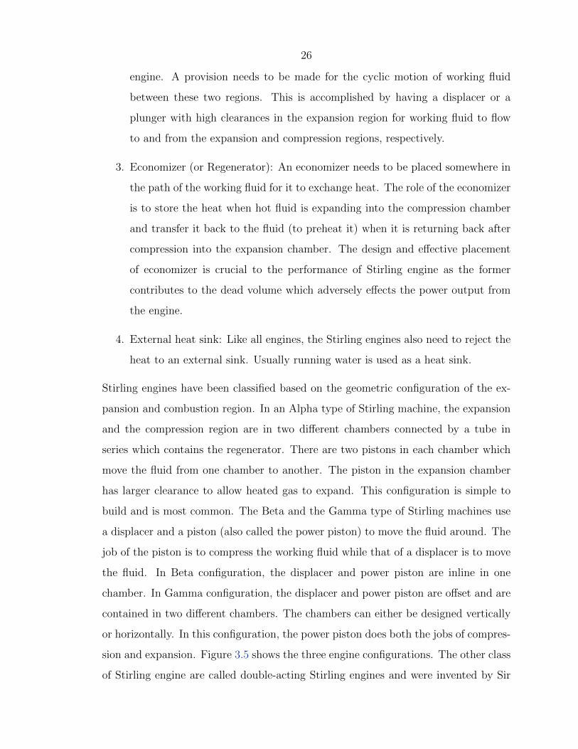
Stirling engines have been classified based on the geometric configuration of the ex-
pansion and combustion region. In an Alpha type of Stirling machine, the expansion
and the compression region are in two different chambers connected by a tube in
series which contains the regenerator. There are two pistons in each chamber which
move the fluid from one chamber to another. The piston in the expansion chamber
has larger clearance to allow heated gas to expand. This configuration is simple to
build and is most common. The Beta and the Gamma type of Stirling machines use
a displacer and a piston (also called the power piston) to move the fluid around. The
job of the piston is to compress the working fluid while that of a displacer is to move
the fluid. In Beta configuration, the displacer and power piston are inline in one
chamber. In Gamma configuration, the displacer and power piston are offset and are
contained in two different chambers. The chambers can either be designed vertically
or horizontally. In this configuration, the power piston does both the jobs of compres-
sion and expansion. Figure 3.5 shows the three engine configurations. The other class
of Stirling engine are called double-acting Stirling engines and were invented by Sir
27
William Siemens [42]. These have four alpha Stirling engines connected in series. The
vertical Gamma engine configuration with double-acting piston has theoretically the
highest possible mechanical efficiency (80.9%) because of the symmetric gas pressure
patterns acting on each side of the piston [43, 74].
(a) Alpha (b) Beta (c) Gamma
Figure 3.5: Schematic of the three types of Stirling engine.
3.7 Review of Stirling Engine Optimization
The recent interest in Stirling engines have spurred numerous studies related to the
factors which contribute to the Stirling cycle performance and power output. The
study done by Kaushik et al. concluded that the heat conductance between engine
and the reservoir and imperfect regeneration coefficient are the important parameters
which effect engine performance [75, 76]. Timoumi et al. developed a numerical
model by taking into account the various losses inside the engine and concluded
that the reduction in regenerator matrix porosity and conductivity led to increased
performance of the Stirling engine [77]. Asnaghi et al. performed a thermodynamic
analysis for the SOLO 161 Solar Stirling engine and concluded that the work output
is maximum when the phase angle between the two pistons is equal to 90 degrees
while the efficiency is maximum when the angle is around 110 degrees [78]. Costea at
al. developed mathematical model describing the irreversible process in solar Stirling
engine. They conclude that the pressure loss due to fluid friction inside the engine,

28
and the mechanical friction between moving parts decrease the efficiency in the engine
by 50% when compared with ideal Stirling cycle efficiency [79].
Based on above studies the following conclusions can be made about current state
of art in Stirling cycle performance:
1. The regenerator volume, matrix porosity and the material’s thermal conductiv-
ity play an important role in Stirling engine performance.
2. The dead volume contributes to about 50% loss in engine efficiency.
3. Flow losses associated with regenerator need to be minimized.
29
Chapter 4
The Stirling Engine: A Solution toEnergy-Water Nexus
4.1 Overview
The ability of the Stirling engine to operate on green fuels and contribute zero in
operation to the green house gas emissions makes it an ideal candidate to solve the
energy-water nexus described earlier in the thesis. With recent interest by NASA,
DOE and other private companies to adapt the Stirling cycle for cleaner power pro-
duction provides a justification to use it as a replacement for current diesel and electric
pumps being used to pump groundwater. With this in mind, a conceptual design of
solar-powered Stirling engine using a Fresnel lens is developed to generate power to
operate water pumps in developing countries.
4.2 Design Objectives
The goal is to develop a 4kW Stirling engine which would be able to lift water from
150 feet at 75 gallons per minute. The numbers are chosen based on the average farm
size holding and power of existing pumps used by farmers in developing countries.
The design should be flexible to adapt to use other fuels (e.g. biomass, rice pellets)
which are easily available on the farm. The other consideration is to use commercially
available materials and off the shelf parts to make it cost effective and robust.

30
4.3 Design Challenges
4.3.1 Stirling engine
The main challenge in the Stirling engine design is the engine dead volume and the
pressure seals for the pistons. The pressure seals are the weakest link in the design of
the Stirling engine as the thermal efficiency is proportional to both the mean engine
pressure and also the mass of the working fluid. The thermal efficiency of the Stirling
engine also depends on the temperature difference between hot and cold part, hence
there should be an efficient heat transfer from the heat source to the hot part and
from the cold part to the sink. The other constraint is the choice of working material.
Unlike the reciprocating engine (e.g. gasoline engine or diesel engine), the hot end of
the Stirling engine is continuously exposed to the maximum temperature and hence
thermal stresses. This puts a metallurgical constraint on the choice material for
the Stirling engine. On the other hand, the reciprocating engines see the maximum
temperature only momentarily and thus have wider range of possibilities for the choice
of material.
The other challenge is the efficient transfer of heat from the heat source, which in
our case is the solar radiation, to the working fluid. Using solid metal like copper rod
to heat the working fluid is not efficient as it creates local hotspots in the expansion
region. The outside of the engine needs to be insulated very well to prevent thermal
heat losses to the surroundings. At the same time, the engine should be able to
effectively reject the heat to the sink to cool down the working fluid.
4.3.2 Solar concentrator
The most common type of solar concentrators are the Compound Parabolic Concen-
trator (CPC) which reflect the sun rays to a point (called the receiver). The heat
from the receiver is then removed by using a heat exchanger and is used to heat the
working fluid (e.g. to create steam as in solar thermal power plants). CPC are made
up of highly reflecting mirrors which operate on principle of total internal reflection.

31
The other class of concentrators make use of Fresnel lens [80], which are cost effective
and have a higher tolerance to the incoming solar radiation angle. However, almost
all the concentrators need solar tracking as their performance drops drastically for
diffused radiation. The dual axis tracking mechanism increases the efficiency but adds
a significant cost to the solar thermal energy system.
From the energy balance perspective, the solar concentrator will absorb incoming
radiation till there is equilibrium with the lost thermal energy to the surroundings.
Similarly, the receiver’s temperature (which in our design will transfer heat to the
working fluid inside the engine) will continue to rise till a steady state is reached
between the absorbed solar energy, the convective heat transfer from the receiver
to the working fluid, and the radiative and conductive heat losses to the surround-
ings. Hence the location, temperature and humidity of surroundings, and seasonality
become critical in successful concentration and transfer of energy to the working fluid.
4.4 The Conceptual Design
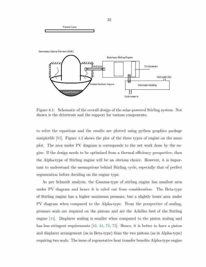
Taking into account the design requirements and challenges, a solar powered Beta-
type of Stirling engine with a Fresnel lens concentrator is recommended as a solution
for sustainable water pumping. Figure 4.1 shows the schematic of the proposed
system. It consist of a Fresnel lens with a secondary optical element, a heat energy
reservoir, a Beta-type Stirling generator and the waste heat utilization system which
also acts as sink for the engine. Each of the components are discussed in detail below.
4.4.1 Stirling engine selection
To decide on the type of Stirling engine, Schmidt analysis [81] is done to estimate the
work done by the three types of Stirling engine for the given hot and cold tempera-
tures. The Schmidt analysis preserves all the assumptions of the ideal Stirling cycle,
except that the volume of compression and expansion chamber vary sinusoidally dur-
ing transfer of fluid [42, 82]. Even though this assumption is not perfect, it is more
realistic when compared to the ideal Stirling cycle [42]. A python script is written
32
Figure 4.1: Schematic of the overall design of the solar-powered Stirling system. Notshown is the drivetrain and the support for various components.
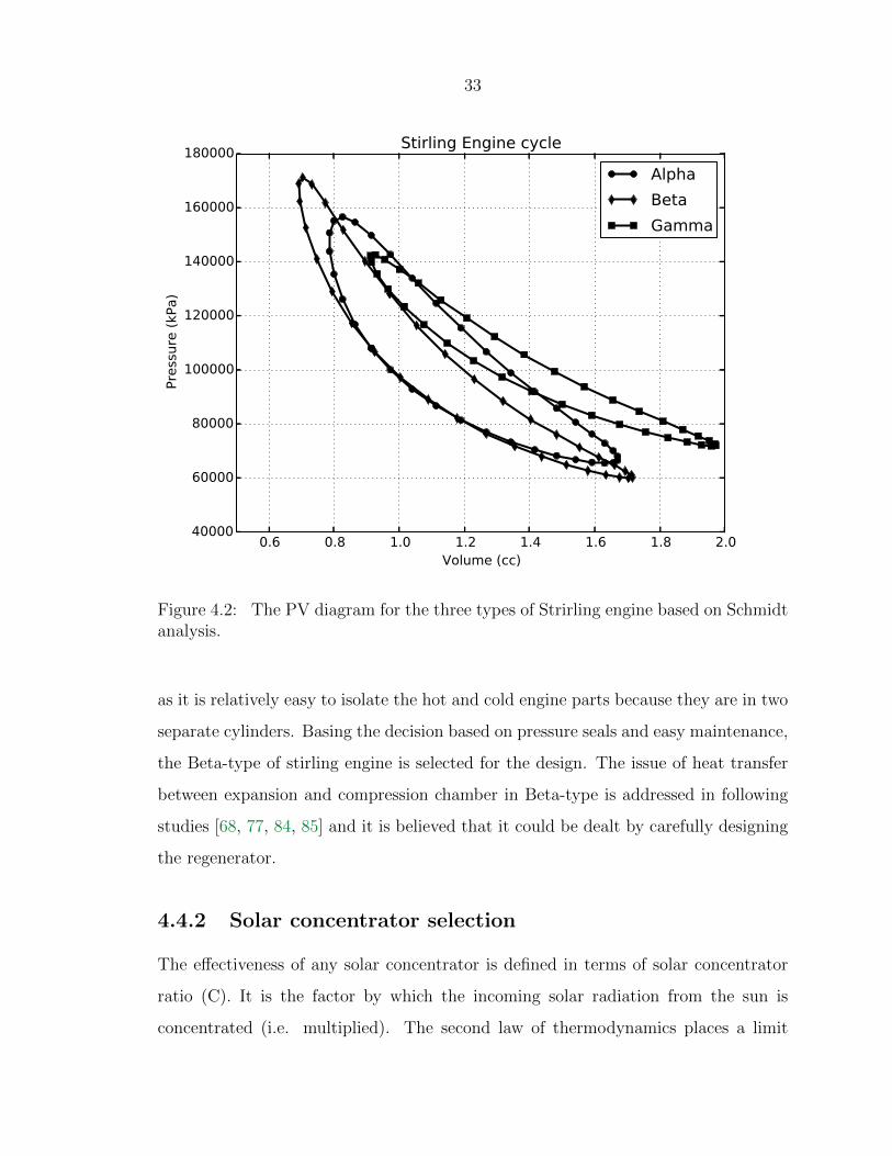
to solve the equations and the results are plotted using python graphics package
matplotlib [83]. Figure 4.2 shows the plot of the three types of engine on the same
plot. The area under PV diagram is corresponds to the net work done by the en-
gine. If the design needs to be optimized from a thermal efficiency perspective, then
the Alpha-type of Stirling engine will be an obvious choice. However, it is impor-
tant to understand the assumptions behind Stirling cycle, especially that of perfect
regeneration before deciding on the engine type.
As per Schmidt analysis, the Gamma-type of stirling engine has smallest area
under PV diagram and hence it is ruled out from consideration. The Beta-type
of Stirling engine has a higher maximum pressure, but a slightly lesser area under
PV diagram when compared to the Alpha-type. From the perspective of sealing,
pressure seals are required on the pistons and are the Achilles heel of the Stirling
engine [44]. Displacer sealing is smaller when compared to the piston sealing and
has less stringent requirements [42, 44, 72, 73]. Hence, it is better to have a piston
and displacer arrangement (as in Beta-type) than the two pistons (as in Alpha-type)
requiring two seals. The issue of regenerative heat transfer benefits Alpha-type engine
33
0.6 0.8 1.0 1.2 1.4 1.6 1.8 2.0Volume (cc)
40000
60000
80000
100000
120000
140000
160000
180000Pre
ssure
(kP
a)
Stirling Engine cycle
Alpha
Beta
Gamma
Figure 4.2: The PV diagram for the three types of Strirling engine based on Schmidtanalysis.
as it is relatively easy to isolate the hot and cold engine parts because they are in two
separate cylinders. Basing the decision based on pressure seals and easy maintenance,
the Beta-type of stirling engine is selected for the design. The issue of heat transfer
between expansion and compression chamber in Beta-type is addressed in following
studies [68, 77, 84, 85] and it is believed that it could be dealt by carefully designing
the regenerator.
4.4.2 Solar concentrator selection
The effectiveness of any solar concentrator is defined in terms of solar concentrator
ratio (C). It is the factor by which the incoming solar radiation from the sun is
concentrated (i.e. multiplied). The second law of thermodynamics places a limit

34
on the maximum concentration (Cmax) which a body can achieve based on the half-
angle (θs) between the source and the receiver [86–88]. Mathematically, this can be
expressed as:
Cmax =1
sin2θs
For Sun-Earth system, θs is 4.65 mrad and hence Cmax ' 46, 200. However, the
actual concentration achieved by using a solar concentrator like parabolic trough
or a Fresnel lens on the receiver is much lower than Cmax. This is due to optical
defects and the fact that the commercially available concentrators [45] are designed
for half-angle between θs = 0.5 ∼ 1.0 degree. Hence the actual concentration achieved
is in range 3200 ∼ 13000. This assumes that the light ray is nearly parallel at
the concentrator, which requires an expensive tracking mechanism to track the sun
[46, 89]. The maximum efficiency ηs and the temperature Tmax which can be achieved
for a given concentration ratio can be estimated by using Carnot principle and Stefan
Boltzmann Law [56, 57]. For perfect absorptivity, emissivity and no optical losses,
the net solar to work efficiency ηs is given as
η =
(1− σT 4
r
IC
)(1− To
Tr
)Here, I is the incoming solar insolation on Earth (∼ 1000 W m−2) [90], Tr is
the receiver temperature and To is the sink (or ambient) temperature to which heat
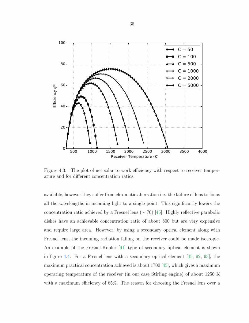
is rejected. Figure 4.3 shows ηs for different concentration ratios. For a given con-
centration ratio, which is limited by the solar concentrator orientation and optical
properties, the temperature at which the efficiency is maximum can be deduced from
the figure. For example, for C = 1000, the maximum efficiency ηs is about 62%
and the optimum operating temperature of the receiver Tr is 1100 K. Note that the
maximum temperature which could be achieved by the receiver is much more than
1100 K but the efficiency if operated at this temperature will be very poor.
The solar concentration ratio plays a crucial role in determining the efficiency
and the net work output of the system. The Fresnel lenses are inexpensive and easily
35
500 1000 1500 2000 2500 3000 3500 4000Receiver Temperature (K)
0
20
40
60
80
100
Eff
icie
ncy
η%
C = 50
C = 100
C = 500
C = 1000
C = 2000
C = 5000
Figure 4.3: The plot of net solar to work efficiency with respect to receiver temper-ature and for different concentration ratios.
available, however they suffer from chromatic aberration i.e. the failure of lens to focus
all the wavelengths in incoming light to a single point. This significantly lowers the
concentration ratio achieved by a Fresnel lens (∼ 70) [45]. Highly reflective parabolic
dishes have an achievable concentration ratio of about 800 but are very expensive
and require large area. However, by using a secondary optical element along with
Fresnel lens, the incoming radiation falling on the receiver could be made isotropic.
An example of the Fresnel-Kohler [91] type of secondary optical element is shown
in figure 4.4. For a Fresnel lens with a secondary optical element [45, 92, 93], the
maximum practical concentration achieved is about 1700 [45], which gives a maximum
operating temperature of the receiver (in our case Stirling engine) of about 1250 K
with a maximum efficiency of 65%. The reason for choosing the Fresnel lens over a

36
parabolic dish or trough is its inexpensive and light weight nature [45, 80, 94, 95].
(b) (a)
Fresnel Lens
SOE (c)
Figure 4.4: (a) The Fresnel-Kohler Secondary Optical Element (SOE) [91], (b) Theprimary Fresnel lens, and (c) The ray diagram of the light from Fresnel lens and SOE.
4.4.3 Solar receiver and heat transport system
To avoid the fluctuations in the solar insolation, the solar receiver system is designed
in a way that it also functions as a thermal storage reservoir. Instead of directly con-
centrating the light on the heater head of the engine, it is allowed to fall on a spherical
dish which has molten sodium inside it. Helium is preferred as the working fluid for
the Beta-type Stirling engine as it offers a higher compression ratio for a given volume.
This is because of higher degrees of freedom for the Helium molecule as compared to
air. Hydrogen would have been an ideal choice, but its combustible nature presents
a threat for on-farm applications and would make the system expensive.
Molten alkali metals are used to transfer the heat from the nuclear reactors which
are used in space applications [96, 97]. Molten alkali metals have large specific thermal
conductivity and specific heat [98]. Their large boiling point (e.g. for liquid sodium is
about 900 degree C) allows for higher thermal efficiency [98, 99]. They have been used
by various space agencies [99–101] to transfer heat from the nuclear reactor (used to
37
generate power in space) to the heat sink. However, when used in nuclear reactors,
the liquid metals become radioactive due to neutron bombardment and require proper
shielding [98].
For the present case, molten alkali metals are good choice when compared to water
because the latter has high latent heat of vaporization. Also, since our utility does
not require any sort of nuclear fission process, hence there is almost no chance of
liquid metals becoming radioactive. When the solar insolation is concentrated onto
the half-sphere disc (figure 4.1), the liquid sodium vaporizes and condenses on the
head of the heat-pipe. The heat-pipe transfers the heat to the engine head in a nearly
isothermal manner. The condensed metal vapors are absorbed by a wick and the cycle
repeats. Andraka et al. at Sandia National Labs [102] have reported an increase of
heat transfer efficiency from 23.2% to 28.1% due to isothermal heating of the engine
head as opposed to direct heating.
To transfer the heat from the cold part of the Stirling engine to the heat sink, a
water-glycol coolant is circulated using a pump. The power to drive the pump is a
parasite loss ( 5-6%) for the engine power output [103]. The heat in the coolant is
then used to heat the water in the tank. The heated water is used by farmers for seed
germination, farm facility cleaning and poultry [104].
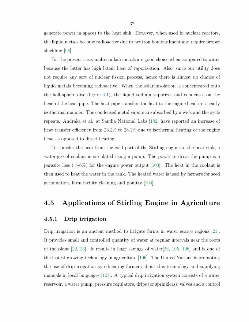
4.5 Applications of Stirling Engine in Agriculture
4.5.1 Drip irrigation
Drip irrigation is an ancient method to irrigate farms in water scarce regions [21].
It provides small and controlled quantity of water at regular intervals near the roots
of the plant [22, 23]. It results in huge savings of water[23, 105, 106] and is one of
the fastest growing technology in agriculture [106]. The United Nations is promoting
the use of drip irrigation by educating farmers about this technology and supplying
manuals in local languages [107]. A typical drip irrigation system consists of a water
reservoir, a water pump, pressure regulators, drips (or sprinklers), valves and a control

38
system [21]. The pump in the drip irrigation system could be used to pump water
from the ground and store it in a man-made water reservoir (e.g.: storage tank). The
water is then distributed via low pressure pump to the drips which supply water near
the roots of the plant. Alternatively, if there exists a natural water reservoir (e.g.:
nearby lake, river) the water can be pumped directly from the reservoir directly to
the drip system. The pumping requirements in former case is set by the pressure head
of the water, while in the later case it is set by the area which needs to be irrigated
(i.e. the mass flow rate). In both the situations, the pump can be powered by a solar
powered Stirling engine. Figure 4.5 shows the schematic of Stirling Drip Irrigation
(SDI) system in which the water is pumped from the water reservoir to the drips.
Pump Stirl
ing
Gen
erat
or
Water Source
Gate Valve
Pressure Relief Valve
Solar Radiation
Fresnel Lens
Drips
~
AC Supply
Figure 4.5: Schematic of Stirling Drip Irrigation (SDI) system.
To size the Stirling engine power output, let us consider the case for the irrigation
needs of an average farmer in India. Assuming that there exist a 15 feet deep water
39
canal which is used as a reservoir to irrigate a perfectly flat acre of land 1 feet deep
in 1 hour. The efficiency of a typical pump which is currently being used by farmers
in India is in range 40 - 80% [13]. Assuming the alternator efficiency as 55% and the
pump efficiency as 60%, the total Stirling engine power output required is about 1.25
kW.
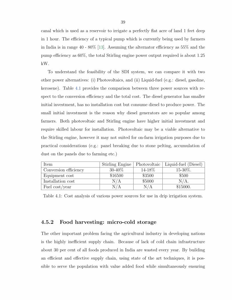
To understand the feasibility of the SDI system, we can compare it with two
other power alternatives: (i) Photovoltaics, and (ii) Liquid-fuel (e.g.: diesel, gasoline,
kerosene). Table 4.1 provides the comparison between three power sources with re-
spect to the conversion efficiency and the total cost. The diesel generator has smaller
initial investment, has no installation cost but consume diesel to produce power. The
small initial investment is the reason why diesel generators are so popular among
farmers. Both photovoltaic and Stirling engine have higher initial investment and
require skilled labour for installation. Photovoltaic may be a viable alternative to
the Stirling engine, however it may not suited for on-farm irrigation purposes due to
practical considerations (e.g.: panel breaking due to stone pelting, accumulation of
dust on the panels due to farming etc.)
Item Stirling Engine Photovoltaic Liquid-fuel (Diesel)Conversion efficiency 30-40% 14-18% 15-30%.Equipment cost $16500 $3500 $500Installation cost N/A $5000 N/A.Fuel cost/year N/A N/A $15000.
Table 4.1: Cost analysis of various power sources for use in drip irrigation system.
4.5.2 Food harvesting: micro-cold storage
The other important problem facing the agricultural industry in developing nations
is the highly inefficient supply chain. Because of lack of cold chain infrastructure
about 30 per cent of all foods produced in India are wasted every year. By building
an efficient and effective supply chain, using state of the art techniques, it is pos-
sible to serve the population with value added food while simultaneously ensuring

40
remunerative prices to the farmers. The surplus of cereals, fruits, vegetables, milk,
fish, meat and poultry can be processed as value added food products and marketed
aggressively both locally and internationally. A summary of the problems faced in
the cold chain sector in the developing countries are as follows:
1. There is an infrastructure gap of 60% (37 million tons) of required cold storage
capacity in India; similar is the case in other developing countries.
2. The cold storages that are currently installed use over 30000 MW of power. The
energy costs account for over 30% of the overall running cost of a cold storage
facility.
3. Further, the grid supply is highly erratic and conventional cold storage systems
use diesel as backup.
4. Given the perishable nature, customer-in-hand quality deteriorates significantly
due to lack of good storage facilities.
5. In the absence of a cold storage and related cold chain facilities, the farmers are
forced to sell their produce immediately after harvest which results in low price
realization to farmers.
To curb the shortage of cold storages in developing countries, the idea of a micro
cold-storage is proposed [108]. It makes use of a Stirling engine generator to drive the
compressor used in the refrigeration cycle. Since Stirling engines are best suited for
stationary operations, the proposed idea is suited for an on-farm small cold-storage
(∼ 2 − 5 tonnes capacity). For mobile operations, such as carrying the cold-storage
on a truck, use of photovoltaics is suggested. Figure 4.6 shows the sketch of the micro
cold-storage system. The Stirling power source is not shown in the figure.
The system consist of three main units: the power supply, the storage compart-
ment and a thermal unit. During the day, the compartment is cooled by using the
vapor compression cycle. The thermal unit takes a part of the cooled refrigerant,
before it enters the evaporator, to produce ice. This ice is kept in a well insulated

41
Storage Compartment
Cold Air Vents
Compressor
Expansion Valve
Cond
ensor
Evap
orator
Refrigera8on Unit
Secon
dary
Evap
orator
To Compressor Thermal Unit
Figure 4.6: Sketch of the micro-cold storage. The refrigeration unit shows themodified vapor compression cycle.
thermal unit and is connected to the storage compartment by heat-pipes. At nights
(or when direct cooling is not enough), the refrigeration effect is transferred from
thermal unit to the compartment through the heat-pipes. This eliminates the need of
the main battery which is usually required in solar powered applications. However, a
small battery is used to power a small blower which is required to transfer heat from
thermal unit into the main compartment. Since the cold-storage unit is proposed for
outside use, it takes the advantage of natural convection thereby lowering the blower
fan requirements.
42
Chapter 5
Conclusion
5.1 Conclusion
The main goal of this thesis is to provide sustainable energy solutions to the two
major issues of irrigation and food harvesting in developing countries. The problem
of irrigation is two fold: groundwater is depleting at an alarming rate, and the energy
required to pump the groundwater comes by burning fossil fuels. The increase in
demand for food for our growing population has further elevated the groundwater
usage, which in turn requires more energy. The problem of food harvesting is due to
highly inefficient cold-supply chain in developing countries. The existing cold-storages
make use of electricity, which in turn comes by burning fossil fuels. In India alone,
the problem is further worsened by the acute shortage of about 37 million tonnes of
cold-storage. This has made agriculture highly unsustainable and one of the most
energy intensive industry.
As a solution to the energy part of both the problems, the use of solar energy
is suggested. The reason for choosing solar is because of the ample solar insolation
which developing nations like India and China receive. To convert solar radiation
into electrical energy, the use of Stirling engine is suggested. A conceptual design
of solar-powered Stirling generator is resented. For easy maintenance, the Beta-type
of Stirling engine is selected over Alpha and Gamma Stirling engines. To make the
system cost-effective, a Fresnel lens with a secondary optical element are used as solar
concentrator. The secondary element helps to collimate the light and make the solar
43
insolation isotropic thereby increasing the concentration ratio. Molten alkali metals
are use as a thermal reservoir for the heat which is then transferred to the working
fluid by using heat-pipes. To make the system more efficient, the waste heat from the
engine is transferred to heat the water which could be used for on-farm operations.
Water-glycol is used as a coolant because of its high heat-transfer coefficient.
For irrigation to consume less water, the use of drip irrigation is suggested. By
combining the solar-powered Stirling generator with the drip irrigation, it is envi-
sioned that not only will irrigation consume less water but also do so in a sustainable
way. It is the first time the use of such a system has been proposed. While one could
use photovoltaics instead of Stirling engine to convert heat into electrical energy,
the social barriers like vandalism and theft pose a major security concern to pho-
tovoltaics thereby limiting its use for on-farm applications. From cost perspective,
a photovoltaic system would probably be cheaper than a Stirling system. However,
from an engineering perspective, for the same amount of concentrated solar radiation,
Stirling engine is about 10% more efficient than photovoltaics. With renewed interest
from NASA and private companies in Stirling technology, it is hoped that the cost to
built a Stirling engine would come down.
The problems faced by the agriculture industry today are man-made and could
be described as the tragedy of commons. One one hand, engineers can come up with
sustainable solutions, but it is up to the government and individuals to make an
effort to use them. Government needs to educate farmers about technologies like drip
irrigation and regulate the amount of groundwater which could be withdrawn. Pilot
projects should be set-up to increase the understanding of new technologies. It is for
a reason why it is called a nexus.
5.2 Future Work
While this thesis provides a conceptual design of a solar-powered Stirling generator,
there still remain many practical challenges to make it a feasible solution. For ex-
ample, the orientation of Fresnel lens needs to be continuously adjusted to track the

44
sun, which adds an extra cost to the system. Also, research needs to be done for the
high quality materials which are needed to insulate the hot space enclosure so that
heat could be effectively transferred to the molten alkali metals from the concentrated
light. One possible way to avoid use of hot space enclosure is to keep the focal point
of the Fresnel lens inside the engine head to directly heat the working fluid. This
would require a study of various optics have high transmission ratios and excellent
resistance to high temperatures.
The performance of a Stirling engine depends on the ambient temperature. If
water is not available as a coolant, then the efficiency of the engine will drop on a
hot day (which is usually the case for on-farm conditions). A detailed theoretical
and experimental analysis needs to be performed to identify the potential coolants
and to characterize there heat-transfer coefficients. The present design assumed that
helium is readily available to be used as working fluid. Since the major producer of
helium gas in the world is US, it may pose a challenge to import helium in developing
countries like India and China. Hence, it is suggested to look into other possible
working fluids which have high thermal conductivity, low viscosity and diffusivity.
There is no available data for the on-farm technologies which use molten alkali
metals. Though they are an excellent thermal reservoir, the liquid metal containing
space needs to be properly sealed to avoid any contact with air or water. While the
guidelines for safe handling of alkali metals exist, it is strongly suggested to carry out
thorough experiments on sealing material needed for a safe design.
As the cost of photovoltaic panels is decreasing, it may be viable option to build
a hybrid modular system which consists of a Stirling engine and a photovoltaic array
as a means to generate electricity. For example, during a sunny day, the system could
directly use photovoltaic panels to convert solar energy into electricity. On a less
sunny day, the waste from the livestock could be burned to provide thermal energy
to the Stirling engine. In another scenario, if there is a need to expand the power
output from a existing photovoltaic water pumping system, a Stirling engine could be
added with no extra area penalty. However, a detailed engineering analysis is needed
to reduce the number of components in such a hybrid design.

45
Lastly, the selection of Beta-type Stirling engine was made due to a larger area
under PV diagram which was based on Schmidt analysis. While Beta-type Stirling
engine require less maintenance than Alpha- and Gamma-type Stirling engine, the real
world processes which any Stirling engine would follow are far from what is assumed in
Schmidt cycle. There do exist other class of Stirling engines like Free-Piston Stirling
engine which were not investigated in this study and may perform better than the
Beta-type Stirling engine. A theoretical investigation based on Schmidt and Adiabatic
analysis for both the engine could provide useful guidelines on selection of engine
type.
46
References
[1] P. H. Gleick. The World’s Water Volume 7: The Biennial Report on Freshwater
Resources. Island Press, 2011.
[2] Water security and global water agenda. Technical report, United Nations
University - Institute for Water Environment and Health, 2013.
[3] J. Bruinsma. World agriculture: towards 2015/2030. Technical report, Food
and Agriculture Organization of United Nations and UN-Water, 2003.
[4] Groundwater resources and irrigated agriculture. Technical report, Perspective
papers: Global Water Partnership.
[5] Managing water under uncertainity and risk. Technical report, The United
Nations World Water Development Report 4.
[6] G.N. Gilbert. World Population: A Reference Handbook. Abc-Clio Incorpo-
rated, 2005.
[7] J. Qiu. China faces up to groundwater crisis. Nature, 466(308), 2010.
[8] States of India. Statistics on net and gross irrigation. In Centre for Monitoring
Indian Economy Pvt. Ltd (CMIE), 2012.
[9] International Groundwater Resources Assessment Centre (IGRAC) (Utrecht).
Overview of IGRAC’s On-line Services. IGRAC, 2005.
[10] S. Siebert, J. Burke, J. M. Faures, K. Frenken, J. Hoogeveen, P. Doell, and
F. T. Portman. Groundwater use for irrigation-a global inventory. Journal of
Hydrology and Earth System Science, 14:1863–1880, 2010.
47
[11] T. Shah. Climate change and groundwater: India′s opportunities for mitigation
and adaptation. IOP Environmental Research Letters, 4, 2009.
[12] T. Shah, A. D. Roy, A. S. Qureshi, and J. Wang. Sustaining Asia′s groundwater
boom: an overview of issues and evidence. Natural Resources Forum, 27:130–
141, 2003.
[13] T. Shah, C. Scott, A. Kishore, and A. Sharma. Energy-irrigation nexus in
South Asia: improving groundwater conservation and power sector viability.
Technical report, Colombo: International Water Management Institute, 2004.
[14] T. Shah. Innovations in groundwater management: examples from India . Tech-
nical report, Colombo: International Water Management Institute, 2011.
[15] M. Rodell, I. Velicogna, and J. S. Famiglietti. Satellite-based estimates of
groundwater depletion in India. Nature Letter, 460:999–1002, 2009.
[16] V. M. Tiwari, J. Wahr, and S. Swenson. Dwindling groundwater resources
in Northern India, from satellite gravity observations. Geophysical Research
Letters, 36:L18401, 2009.
[17] J. Wang, S. Rothausen, D. Conway, L. Zhang, W. Xiong, I. P. Holman, and
Y. Li. China’s water - energy nexus: greenhouse-gas emissions from groundwa-
ter use for agriculture. IOP Environmental Research Letters, 7, 2012.
[18] EPA. Sources of Greenhouse Gas Emissions. Technical report, United States
Environment Protection Agency, 2013.
[19] Diesel engine development in view of reduced emission standards. Energy,
33(2):264 – 271, 2008.
[20] S. Singh. Pumping Punjab dry. Technical report, IEEE SPECTRUM, 2010.
[21] D. Goldberg, B. Gornat, and D. Rimon. Drip Irrigation: principles, design,
and agricultural practices. Drip Irrigation Scientific Publications, 1976.

48
[22] L. Bernstein and L. E. Francois. Comparisons of drip, furrow, and sprinkler
irrigation. Soil Science, 115:73–86, 1973.
[23] R. K. Sivanappan. Economics of drip irrigation method in small and marginal
farms. Technical report, Indian Council of Agricultural Research (India) ICAR,
1978.
[24] The human right to water and sanitation. Technical Report 292.
[25] H. S. Burness and T. C. Brill. The role for policy in common pool groundwater
use. Resource and Energy Economics, 23(1):19 – 40, 2001.
[26] D. L. Danielopol, C. Griebler, A. Gunatilaka, and J. Notenboom. Present state
and future prospects for groundwater ecosystems. Environmental Conservation,
30:104–130, 5 2003.
[27] T. Gleeson, W. M. Alley, D. M. Allen, M. A. Sophocleous, Y. Zhou,
M. Taniguchi, and J. VanderSteen. Towards sustainable groundwater use: Set-
ting long-term goals, backcasting, and managing adaptively. Ground Water,
50(1):19–26, 2012.
[28] New York Times. Groundwater depletion is detected from space, March 30
2011.
[29] R. Kondepati. Agricultural groundwater management in Andhra Pradesh India:
A focus on free electricity policy and its reform. International Journal of Water
Resources Development, 27:375–386, 2011.
[30] D. L. Martin, T. W. Dorn, S. R. Melvin, A. J. Corr, and W. L. Kranz. Evaluat-
ing energy use for pumping irrigation water. In Proceedings of the 23rd Annual
Central Plains Irrigation Conference, Burlington, CO, 2011.
[31] Y. Wada, L. P. H. V. Beek, F. C. S. Weiland, B. F. Chao, Y.H. Wu, and M. F. P.
Bierkens. Past and future contribution of global groundwater depletion to sea-
level rise. Geophysical Research Letters, 39(9), 2012.
49
[32] G. Boyle. Renewable Energy: power for a sustainable future. OUP Oxford,
2012.
[33] G. Berndes. Bioenergy and waterthe implications of large-scale bioenergy pro-
duction for water use and supply. Global Environmental Change, 12(4):253 –
271, 2002.
[34] T. S. Schmidt, R. Born, and M. Schneider. Assessing the costs of photovoltaic
and wind power in six developing countries. Nature Climate Change, 2(7):548
– 553, 2012.
[35] D. Y. Goswami and F. Kreith. Principles of solar engineering. Taylor & Francis
Group, 2000.
[36] B. K. Sovacool, A. L. D. Agostino, and M. J. Bambawale. The socio-technical
barriers to Solar Home Systems (SHS) in Papua New Guinea: Choosing pigs,
prostitutes, and poker chips over panels . Energy Policy, 39(3):1532 – 1542,
2011.
[37] T. D. Short and P. Thompson. Breaking the mould: solar water pumpingthe
challenges and the reality. Solar Energy, 75(1):1 – 9, 2003.
[38] A. Blaga. Use of plastics in solar energy applications. Solar Energy, 21(4):331
– 338, 1978.
[39] Microgen Engine Corporation. Microgen Stirling Engine. Peterborough PE2
6TE, UK.
[40] OkoFEN Forschungs und EntwicklungsgesmbH. OkoFEN-e Pellet Boiler. 4133
Niederkappel, Austria.
[41] R. Stirling. Improvements of diminishing the consumption of fuel, and in par-
ticular an engine capable of being applied to the moving of machinery on a
principle entirely new. United States Patent, Patent No. 81, 1817.
[42] G. Walker. Stirling-cycle machines. Clarendon Press, Oxford, 1973.

50
[43] J. R. Senft. An introduction to Stirling engines. Moriya Press, 1993.
[44] G. Walker and J. R. Senft. Free piston Stirling engines. Springer-Verlag, 1985.
[45] L. B. Johansson. Renewable energy: sources for fuels and electricity. Island
Press, 1993.
[46] G. C. Bakos. Design and construction of a two-axis Sun tracking system for
parabolic trough collector (PTC) efficiency improvement. Renewable Energy,
31:2411 – 2421, 2006.
[47] W. R. Martini. Stirling engine design manual. Technical report, U.S. Depart-
ment of Energy, 1983.
[48] L. S. Mason. A comparison of Brayton and Stirling space nuclear power systems
for power levels from 1 kilowatt to 10 megawatts. In Space Technology and
Applications International Forum, pages 1017–1022, 2001.
[49] International Atomic Energy Agency. IAEA Annual Report for 2005.
[50] M. D. Cambell, J. D. King, H. M. Wise, B. Handley, and M. D. Campbell. The
role of nuclear power in space exploration and the associated environmental is-
sues: an overview. In Report by the Uranium Committee of the Energy Minerals
Division, AAPG, 2009.
[51] J. Chan, J. G. Wood, and J. G. Schreiber. Development of advanced Stir-
ling radioisotope generator for space exploration. In 24th Symposium on Space
Nuclear Power and Propulsion, pages 615–623, 2007.
[52] John H. Glenn Research Center. Advanced Stirling Radioisotope Generator
(ASRG). 21000 Brookpark Road, Cleveland, OH 44111.
[53] Sunpower Inc. Advanced Stirling Convertor (ASC). 1055 E. State Street - Suite
D, Athens Ohio 45701.
51
[54] R. D. Cockfield and T. S. Chan. Stirling radioisotope isotope generator for
Mars surface and deep space missions. In 37th Intersociety Energy Conversion
Engineering Conference, 2002.
[55] C. W. Smith and M. N. Vise. Energy and empire: a biographical study of Lord
Kelvin. Cambridge University Press, 1989.
[56] F. Sears and M. Zemansky. College Physics. Addison-Wesley, 1991.
[57] G. J. V. Wylen and R. E. Sonntag. Fundamentals of classical Thermodynamics.
Wiley, 1985.
[58] B. Kongtragool and S. Wongwises. Thermodynamic analysis of Stirling engine
including dead volumes of hot space, cold space and regenerator. Journal of
Renewable Energy, 31:345–359, 2006.
[59] N. Parlak, A. Wagner, M. Elsner, and H. K. Soyhan. Thermodynamic analysis
of a gamma type Stirling engine in non-ideal adiabatic conditions. Journal of
Renewable Energy, 34:266–273, 2009.
[60] H. Karabulut, H. S. Yucesu, C. Cinar, and F. Aksoy. Construction and testing
of dish/Stirling solar energy unit. Journal of Energy Institute, 82:207–211, 2009.
[61] W. M. Moscrip. Thermodynamic working fluids for Stirling-cycle reciprocating
thermal machines. United States Patent, US Patent WO82/04098, 1982.
[62] P. Puech and V. Tishkova. Thermodynamic analysis of a Stirling engine in-
cluding regenerator dead volume. Journal of Renewable Energy, 36:872–878,
2011.
[63] S. N. Backhaus and G. W. Swift. Fabrication and use of parallel-plate regener-
ators in thermoacoustic engines. In Proceedings of the 36th Intersociety Energy
Conversion Engineering Conference, Savannah, GA, 2001.
[64] Y. Z. Shan. Oscillatory flow and heat transfer in a Stirling engine regenerator.
PhD thesis, Case Western Reserve University, 1993.

52
[65] M. J. Cheadle, G. F. Nellis, and S. A. Klein. Regenerator friction factor and
Nusselt number information derived from CFD analysis. In Proceedings of the
16th International Cryocooler Conference, Atlanta, GA, 2008.
[66] R. H. Titran and J. R. Stephens. Advanced high temperature materials for
the energy efficient automotive Stirling engine. Journal of Materials for Energy
Systems, 6:114–121, 1984.
[67] M. Dhar. Stirling space engine program. Technical report, National Aeronautics
and Space Administration (NASA), 1999.
[68] C. Cinar, S. Yucesu, T. Topgul, and M. Okur. Beta-type Stirling engine oper-
ating at atmospheric pressure. Journal of Applied Energy, 81-4:351–357, 2005.
[69] D. Mills. Advances in solar thermal electricity technology. Journal of Solar
Energy, 76:19–31, 2004.
[70] C. F. A. Afonso. Recent advances in building air conditioning systems. Applied
Thermal Engineering, 26:1961–1971, 2006.
[71] R. G. Lange and W. P. Carroll. Review of recent advances of radioisotope power
systems. Energy Conversion and Management, 49:393–401, 2008.
[72] T. Finkelstein. Generalized thermodynamic analysis of Stirling cycle engines.
SAE Technical Paper, 118A, 1960.
[73] T. Finkelstein. Thermodynamic analysis of Stirling engines. Journal of Space-
craft and Rockets, 4, 1184-1189.
[74] S. H. Walpita. Development of the solar receiver for a small Stirling engine.
Technical report, Asian Institute of Technology, 1983.
[75] S. C. Kaushik and S. Kumar. Finite time thermodynamic analysis of endore-
versible Stirling heat engine with regenerative losses. Energy, 25:989–1003,
2000.

53
[76] F. Wu, L. Chen, C. Wu, and F. Sun. Optimum performance of irreversible Stir-
ling engine with imperfect regeneration. Energy Conversion and Management,
39:727 – 732, 1998.
[77] Y. Timoumi, I. Tlili, and S. B. Nasrallah. Performance optimization of Stirling
engines. Journal of Renewable Energy, 33:2134–2144, 2008.
[78] A. Asnaghi, S. M. Ladjevardi, P. Saleh Izadkhast, and A. H. Kashani. Ther-
modynamics performance analysis of solar Stirling engines. ISRN Renewable
Energy, 2012, 2012.
[79] M. Costea, M. Feidt, and S. Petrescu. Synthesis on Stirling engine optimization.
Thermodynamic Optimization of Complex Energy Systems, 69:403–410, 1999.
[80] R. Leutz, A. Suzuki, A. Akisawa, and T. Kashiwagi. Design of nonimaging
Fresnel lens for solar concentrators. Solar Energy, 65:379 – 387, 1999.
[81] G. Schmidt. Theorie der Lehmannschen Calorischen Maschine. Zeit Des Vere-
ines deutsch Ing, 15:97 – 112, 1871.
[82] K. Hirata. Schmidt theory for Stirling engines. Technical report, National
Maritime Research Institute, Japan, 1997.
[83] J. D. Hunter. Matplotlib: a 2D graphics environment. Computing In Science
& Engineering, 9:90–95, 2007.
[84] C. Cheng and Y. Yu. Numerical model for predicting thermodynamic cycle and
thermal efficiency of a beta-type Stirling engine with rhombic-drive mechanism.
Renewable Energy, 35:2590 – 2601, 2010.
[85] E. Eid. Performance of a beta-configuration heat engine having a regenerative
displacer. Renewable Energy, 34:2404 – 2413, 2009.
[86] V. Badescu. Maximum concentration ratio of direct solar radiation. Journal of
Applied Optics, 32(12):2187–2189, 1993.

54
[87] P. T. Landsberg and P. Baruch. The thermodynamics of the conversion of
radiation energy for photovoltaics. Journal of Physics A: Mathematical and
General, 22:1911–1926, 1989.
[88] P. Baruch and J. E. Parrott. A thermodynamic cycle for photovoltaic energy
conversion. Journal of Physics D: Applied Physics, 23(6):739, 1990.
[89] P.J. Hession and W.J. Bonwick. Experience with a sun tracker system. Solar
Energy, 32:3 – 11, 1984.
[90] T. Muneer. Solar Radiation and Daylight Models. Taylor & Francis, 2012.
[91] Light Prescriptions Innovators (LPI). Fresnel-Kohler optical design. 2400 Lin-
coln Avenue, Altadena, CA 91001.
[92] P. Benıtez, J. C. Mi nano, P. Zamora, R. Mohedano, A. Cvetkovic, M. Buljan,
J. Chaves, and M. Hernandez. High performance Fresnel-based photovoltaic
concentrator. Optical Express, 18(S1):A25–A40, 2010.
[93] L. W. James. Use of imaging refractive secondaries in photovoltaic concentra-
tors. Technical report, Sandia National Labs, 1989.
[94] A. Davis. Fresnel lens solar concentrator derivations and simulations. In Pro-
ceedings of SPIE, 2011.
[95] E.M. Kritchman, A.A. Friesem, and G. Yekutieli. Efficient Fresnel lens for solar
concentration. Solar Energy, 22:119 – 123, 1979.
[96] K. L. Walker, C. Tarau, and W. G. Anderson. Alkali metal heat pipes for space
fission power. In Nuclear and Emerging Technologies for Space, Albuquerque,
NM, 2013.
[97] L. Mason and C. Carmichael. A small fission power system with Stirling power
conversion for NASA science missions. In Nuclear and Emerging Technologies
for Space, Albuquerque, NM, 2011.
55
[98] I. I. Novikov, A. N. Solovyev, E. M. Khabakhpasheva, V. A. Gruzdev, A. I.
Pridantsev, and M. Ya. Vasenina. Heat transfer and thermophysical properties
of molten alkali metals. The Soviet Journal of Atomic Energy, 1:545–560, 1956.
[99] R. K. Shaltens and J. G. Schreiber. Comparision of conceptual designs for
25kWe advanced Stirling conversion systems for dish electric applications. Tech-
nical report, NASA Lewis Research Center, 1989.
[100] P. G. Salvail and R. R. Carter. Alkali metal handling practices at NASA MSFC.
Technical report, NASA Marshall Space Flight Center, 2002.
[101] J. E. Noble, G. L. Hickman, and T. Grobstein. Alkali metal compatibility
testing of candidate heater head materials for a Stirling engine heat transport
system. In 26th Intersociety Energy Conversion Engineering Conference, La
Grange Park, IL, 1991.
[102] C. E. Andraka, K. S. Rawlinson, T. A. Moss, D. R. Adkins, J. B. Moreno, D. R.
Gallup, P. G. Cordeiro, and S. Johansson. Solar heat pipe testing of the Stirling
Thermal Motors 4-120 Stirling engine. In Proceedings of the 31st Intersociety
Energy Conversion Engineering Conference, 1996.
[103] U.S. Department of Energy Vehicle Technologies Office. Engine Energy Use:
Where Does the Energy Go? 1000 Independence Ave., SW, Washington, DC
20585.
[104] G. Palano. Harvesting the Sun for hot water on farms. Technical report,
Massachusetts Farm Energy Program, 2011.
[105] R. K. Sivanappan and O. Padmakumari. Economics of drip irrigation for water
scarce regions. Technical report, Indian Council of Agricultural Research (India)
ICAR, 1979.
[106] C. D. Gustafson. History and present trends of drip irrigation. Technical report,
California Avocado Society Yearbook, 1979.

56
[107] Drip irrigation manual for farmers in arabic. Technical report, UN water and
FAO, 2012.
[108] P. Mehrotra, P. Singhal, V. Pandey, and D. Gupta. Micro-cold storage. Poster
Presentation at the Dow SISCA Awards Ceremony held at Resnick Institute,
Caltech, 2012.