SUSTAINABLE BUILDING DESIGN FOR TROPICAL CLIMATES · 2015-05-22 · 1.5 Architecture in tropical...
303
SUSTAINABLE BUILDING DESIGN FOR TROPICAL CLIMATES Principles and Applications for Eastern Africa
Transcript of SUSTAINABLE BUILDING DESIGN FOR TROPICAL CLIMATES · 2015-05-22 · 1.5 Architecture in tropical...
SUSTAINABLE BUILDING DESIGN FOR TROPICAL CLIMATESPrinciples and Applications for Eastern Africa
SUSTA
INA
BLE
BU
ILDIN
G D
ESIG
N FO
R T
RO
PIC
AL C
LIMA
TE
S
PR
INC
IPLE
S AN
D A
PP
LICA
TIO
NS FO
R E
AS
TE
RN
AFR
ICA
United Nations Human Settlements Programme (UN-Habitat) P. O. Box 30030, 00100 Nairobi GPO KENYA Tel: 254-020-7623120 (Central Office)
HS/013/15E ISBN: 978-92-1-132644-4
www.unhabitat.org
The project “Promoting Energy Efficiency in Buildings in East Africa” is an initiative of UN-Habitat in collaboration with the United NationsEnvironment Programme (UNEP), the Global Environment Facility (GEF) and the governments of Kenya, Uganda, Tanzania, Rwanda and Burundi.
SUSTAINABLE BUILDINGDESIGN FOR TROPICAL CLIMATESPrinciples and Applications for Eastern Africa
SUSTAINABLE BUILDING DESIGN FOR TROPICAL CLIMATES Principles and Applications for Eastern Africaii
SUSTAINABLE BUILDING DESIGN FOR TROPICAL CLIMATES Principles and Applications for Eastern Africa
First published in Nairobi in August 2014 by UN-Habitat.
Copyright © United Nations Human Settlements Programme 2014
United Nations Human Settlements Programme (UN-Habitat)
P. O. Box 30030, 00100 Nairobi GPO KENYA
Tel: +254-020-7623120 (Central Office)
www.unhabitat.org
HS/013/15E
ISBN: 978-92-1-132644-4
DISCLAIMER
The designations employed and the presentation of the material in this publication do not imply the expression of any opinion
whatsoever on the part of the Secretariat of the United Nations con cerning the legal status of any country, territory, city or area
or of its authorities, or concerning the delimitation of its frontiers or boundaries.
Views expressed in this publication do not necessarily reflect those of the United Nations Human Settlements Programme, the
United Nations, or its Member States.
Excerpts may be reproduced without authorization, on condition that the source is indicated.
ACknowLEDgEMEntS
Project supervisor: Vincent Kitio
Principal author: Prof. Federico M. Butera, Politecnico of Milan, Italy.
Co-authors: Rajendra Adhikari, Niccolò Aste, Politecnico of Milan, Italy.
Background papers: Rajendra Adhikari, Niccolò Aste, Marco Agrò, Michela Buzzetti, Mario Butera, Paola Caputo, Giuliano Dall’O’, Claudio del Pero, Dania Gonzales Couret, Massimiliano Manfren, Manlio Mazzon, Lavinia Tagliabue, Sebastian Lange
Contributors: Marja Edelman, Jerusha Ngungui, Zeltia Blanco, Ruth Maina, Cláudia Amorim, Modest M. Baruti, Fabrizio Leonforte, Farizan d’Avezac de Moran
Editor: Sue Ball
Illustrations: Caterina Fiorani
Design and layout: Andrew Ondoo, Jerusha Ngungui
Printing: UNON, Publishing Services Section, Nairobi

SUSTAINABLE BUILDING DESIGN FOR TROPICAL CLIMATES Principles and Applications for Eastern Africa iii
Table of conTenT
CHAPTER 01: IntRoDuCtIon 1
1.1 Background 11.2 The building sector 41.3 Integrated design 61.4 Construction materials 91.5 Architecture in tropical climates 91.6 A new energy system for cities 10
CHAPTER 02: CLIMAtES AnD buILDIng DESIgn 11
2.1 Climatic parameters 11
2.2 Climates in the East African Community 33
CHAPTER 03: CLIMAtE RESponSIvE buILDIng DESIgn 38
3.1 Passive Design 383.2 Bioclimatic charts 393.3 Site planning 493.5 Natural Ventilation 673.6 Daylighting 813.7 Shading 903.8 Natural cooling 1023.9 Building materials 1073.10 Design guidelines according to EAC climates 1123.11 Lessons from the past 122
CHAPTER 04: EnERgY EFFICIEnt buILDIngS DESIgn 136
4.1 The envelope 1364.2 Building services 1474.2.3 DHW production 1684.3 Hybrid ventilation 1924.4 Existing Buildings 1934.5 Simulation tools 2044.6 Energy Performance Certificates and Green Building Rating Systems 207
CHAPTER 05: DESIgn At CoMMunItY SCALE 224
5.1 Energy and the urban metabolism 2245.2 Water and sanitation 2295.3 Solid waste management 240
CHAPTER 06: REnEwAbLE EnERgY tECHnoLogIES 245
6.1 Solar PV 2456.2 Solar Thermal 2486.3 Wind energy 2536.4 Biomass 2556.5 Hydropower 267
CHAPTER 07: nEt ZERo EnERgY buILDIngS AnD CoMMunItIES 271
7.1 Net Zero Energy Buildings 2717.2 Net Zero Energy Communities 280
gLoSSARY 285
bIbLIogRApHY 291
InDEx 295

SUSTAINABLE BUILDING DESIGN FOR TROPICAL CLIMATES Principles and Applications for Eastern Africaiv
1.1 backgroundClimate change and resource depletion are the main
challenges that mankind has to face in the 21st century. Through its impact on ecology, rainfall, temperature and weather systems, global warming will directly affect all countries. Nobody will be immune to its consequences. However, some countries and people are more vulnerable than others. In the long term, the whole of humanity faces risks but the more immediate risks are skewed towards the world’s poorest and most vulnerable people.
We know that the world is warming and that the average global temperature has increased by around 0.7°C since the advent of the industrial era. We also know that this trend is accelerating: average global mean temperature is rising by 0.2°C every decade. With the global rise in temperature, local rainfall patterns are changing, ecological zones are shifting, the seas are warming and the ice caps are melting.
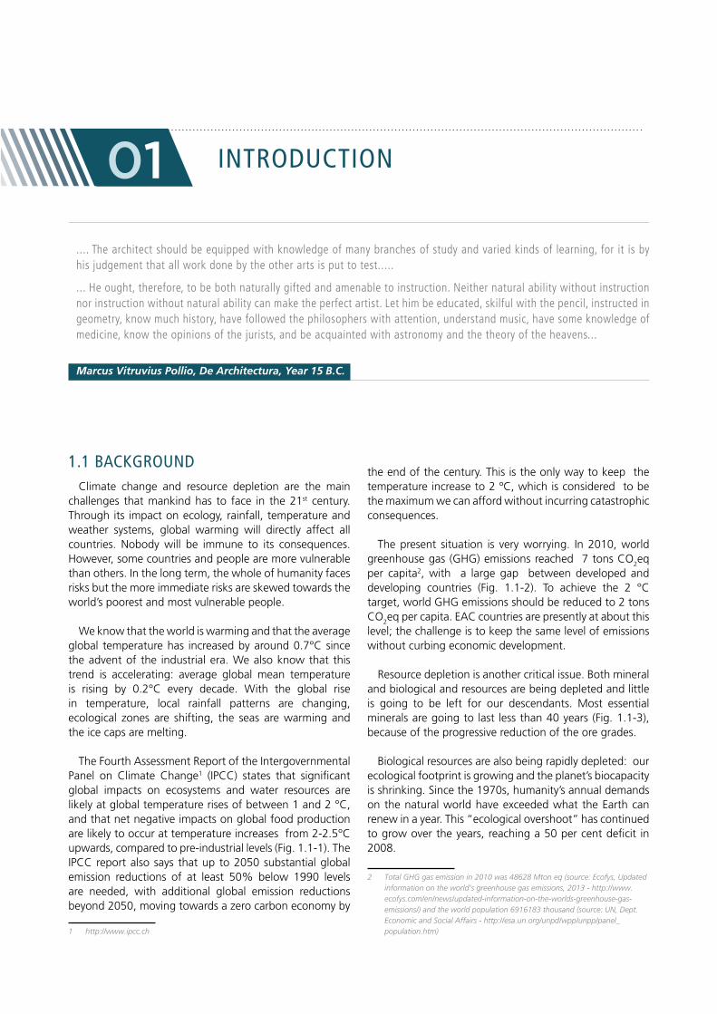
The Fourth Assessment Report of the Intergovernmental Panel on Climate Change1 (IPCC) states that significant global impacts on ecosystems and water resources are likely at global temperature rises of between 1 and 2 °C, and that net negative impacts on global food production are likely to occur at temperature increases from 2-2.5°C upwards, compared to pre-industrial levels (Fig. 1.1-1). The IPCC report also says that up to 2050 substantial global emission reductions of at least 50% below 1990 levels are needed, with additional global emission reductions beyond 2050, moving towards a zero carbon economy by
1 http://www.ipcc.ch
the end of the century. This is the only way to keep the temperature increase to 2 ºC, which is considered to be the maximum we can afford without incurring catastrophic consequences.
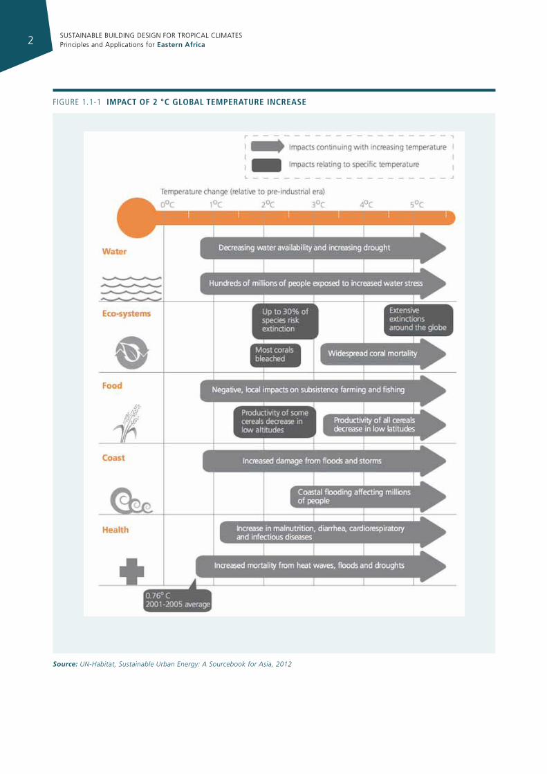
The present situation is very worrying. In 2010, world greenhouse gas (GHG) emissions reached 7 tons CO2eq per capita2, with a large gap between developed and developing countries (Fig. 1.1-2). To achieve the 2 °C target, world GHG emissions should be reduced to 2 tons CO2eq per capita. EAC countries are presently at about this level; the challenge is to keep the same level of emissions without curbing economic development.
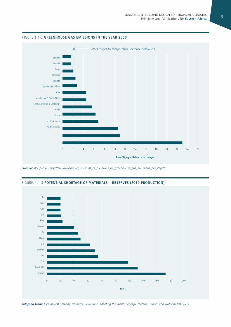
Resource depletion is another critical issue. Both mineral and biological and resources are being depleted and little is going to be left for our descendants. Most essential minerals are going to last less than 40 years (Fig. 1.1-3), because of the progressive reduction of the ore grades.
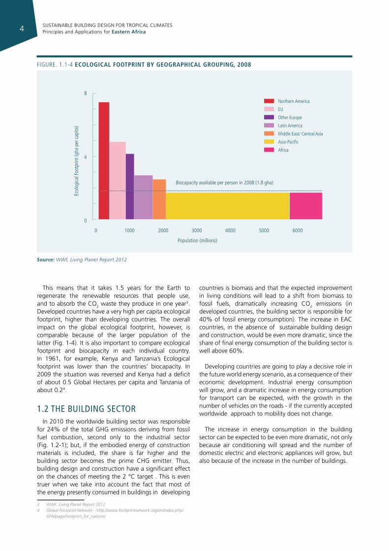
Biological resources are also being rapidly depleted: our ecological footprint is growing and the planet’s biocapacity is shrinking. Since the 1970s, humanity’s annual demands on the natural world have exceeded what the Earth can renew in a year. This “ecological overshoot” has continued to grow over the years, reaching a 50 per cent deficit in 2008.
2 Total GHG gas emission in 2010 was 48628 Mton eq (source: Ecofys, Updated information on the world’s greenhouse gas emissions, 2013 - http://www.ecofys.com/en/news/updated-information-on-the-worlds-greenhouse-gas-emissions/) and the world population 6916183 thousand (source: UN, Dept. Economic and Social Affairs - http://esa.un.org/unpd/wpp/unpp/panel_population.htm)
InTroducTIon
.... The architect should be equipped with knowledge of many branches of study and varied kinds of learning, for it is by his judgement that all work done by the other arts is put to test.....
... He ought, therefore, to be both naturally gifted and amenable to instruction. Neither natural ability without instruction nor instruction without natural ability can make the perfect artist. Let him be educated, skilful with the pencil, instructed in geometry, know much history, have followed the philosophers with attention, understand music, have some knowledge of medicine, know the opinions of the jurists, and be acquainted with astronomy and the theory of the heavens...
Marcus Vitruvius Pollio, De Architectura, Year 15 B.C.
01
SUSTAINABLE BUILDING DESIGN FOR TROPICAL CLIMATES Principles and Applications for Eastern Africa2
Figure 1.1-1 Impact of 2 °c global temperature Increase
Source: UN-Habitat, Sustainable Urban Energy: A Sourcebook for Asia, 2012
SUSTAINABLE BUILDING DESIGN FOR TROPICAL CLIMATES Principles and Applications for Eastern Africa 3
Figure 1.1-2 greenhouse gas emIssIons In the year 2000
Source: Wikipedia - http://en.wikipedia.org/wiki/List_of_countries_by_greenhouse_gas_emissions_per_capita
Burundi
rwanda
Kenya
Tanzania
uganda
Sub-Saharan Africa
Asia
Middle east & North Africa
Central America & Caribbean
World
europe
South America
North America
0 2 4 6 8 10 12 14 16 18 20 22 24 26
tons co2 eq with land use change
2050 target to temperature increase below 2oC
Tin
Lead
gold
Zinc
Silver
Copper
Oil
Nickel
gas
uranium
iron
Coal
Bauxite (Al)
Platinum
0 20 40 60 80 100 120
years
140 160 180 200
Figure. 1.1-3 potentIal shortage of materIals – reserves (2010 productIon)
Adapted from: McKinsey&Company, Resource Revolution: Meeting the world’s energy, materials, food, and water needs, 2011.
SUSTAINABLE BUILDING DESIGN FOR TROPICAL CLIMATES Principles and Applications for Eastern Africa4
This means that it takes 1.5 years for the Earth to regenerate the renewable resources that people use, and to absorb the CO2 waste they produce in one year3. Developed countries have a very high per capita ecological footprint, higher than developing countries. The overall impact on the global ecological footprint, however, is comparable because of the larger population of the latter (Fig. 1-4). It is also important to compare ecological footprint and biocapacity in each individual country. In 1961, for example, Kenya and Tanzania’s Ecological footprint was lower than the countries’ biocapacity. In 2009 the situation was reversed and Kenya had a deficit of about 0.5 Global Hectares per capita and Tanzania of about 0.24.
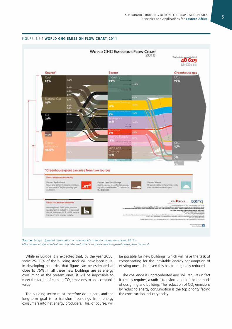
1.2 The buIldIng secTorIn 2010 the worldwide building sector was responsible
for 24% of the total GHG emissions deriving from fossil fuel combustion, second only to the industrial sector (Fig. 1.2-1); but, if the embodied energy of construction materials is included, the share is far higher and the building sector becomes the prime CHG emitter. Thus, building design and construction have a significant effect on the chances of meeting the 2 °C target . This is even truer when we take into account the fact that most of the energy presently consumed in buildings in developing
3 WWF, Living Planet Report 20124 Global Footprint Network - http://www.footprintnetwork.org/en/index.php/
GFN/page/footprint_for_nations/
countries is biomass and that the expected improvement in living conditions will lead to a shift from biomass to fossil fuels, dramatically increasing CO2 emissions (in developed countries, the building sector is responsible for 40% of fossil energy consumption). The increase in EAC countries, in the absence of sustainable building design and construction, would be even more dramatic, since the share of final energy consumption of the building sector is well above 60%.
Developing countries are going to play a decisive role in the future world energy scenario, as a consequence of their economic development. Industrial energy consumption will grow, and a dramatic increase in energy consumption for transport can be expected, with the growth in the number of vehicles on the roads - if the currently accepted worldwide approach to mobility does not change.
The increase in energy consumption in the building sector can be expected to be even more dramatic, not only because air conditioning will spread and the number of domestic electric and electronic appliances will grow, but also because of the increase in the number of buildings.
0
4
8
0 1000 2000 3000 4000 5000 6000
Biocapacity available per person in 2008 (1.8 gha)
Population (millions)
ecol
ogica
l Foo
tprin
t (gh
a pe
r cap
ita)
Northern America
eu
Other europe
Latin America
Middle east/ Central Asia
Asia-Pacific
Africa
Figure. 1.1-4 ecologIcal footprInt by geographIcal groupIng, 2008
Source: WWF, Living Planet Report 2012
SUSTAINABLE BUILDING DESIGN FOR TROPICAL CLIMATES Principles and Applications for Eastern Africa 5
While in Europe it is expected that, by the year 2050, some 25-30% of the building stock will have been built, in developing countries that figure can be estimated at close to 75%. If all these new buildings are as energy consuming as the present ones, it will be impossible to meet the target of curbing CO2 emissions to an acceptable value.
The building sector must therefore do its part, and the long-term goal is to transform buildings from energy consumers into net energy producers. This, of course, will
be possible for new buildings, which will have the task of compensating for the inevitable energy consumption of existing ones – but even this has to be greatly reduced.
The challenge is unprecedented and will require (in fact it already requires) a radical transformation of the methods of designing and building. The reduction of CO2 emissions by reducing energy consumption is the top priority facing the construction industry today.
Figure. 1.2-1 World ghg emIssIon floW chart, 2011
Source: Ecofys, Updated information on the world’s greenhouse gas emissions, 2013 - http://www.ecofys.com/en/news/updated-information-on-the-worlds-greenhouse-gas-emissions/
SUSTAINABLE BUILDING DESIGN FOR TROPICAL CLIMATES Principles and Applications for Eastern Africa6
1.3 InTegraTed desIgn
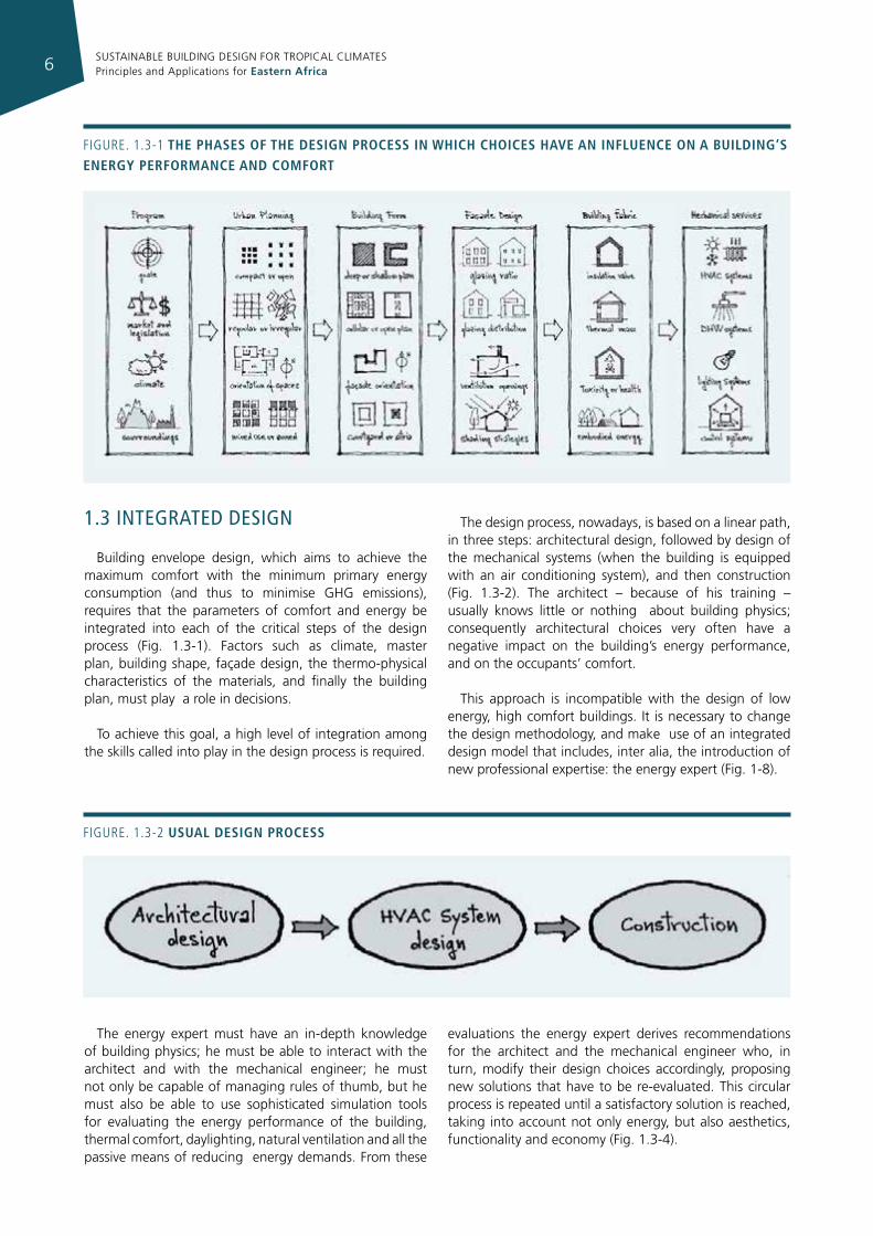
Building envelope design, which aims to achieve the maximum comfort with the minimum primary energy consumption (and thus to minimise GHG emissions), requires that the parameters of comfort and energy be integrated into each of the critical steps of the design process (Fig. 1.3-1). Factors such as climate, master plan, building shape, façade design, the thermo-physical characteristics of the materials, and finally the building plan, must play a role in decisions.
To achieve this goal, a high level of integration among the skills called into play in the design process is required.
The design process, nowadays, is based on a linear path, in three steps: architectural design, followed by design of the mechanical systems (when the building is equipped with an air conditioning system), and then construction (Fig. 1.3-2). The architect – because of his training – usually knows little or nothing about building physics; consequently architectural choices very often have a negative impact on the building’s energy performance, and on the occupants’ comfort.
This approach is incompatible with the design of low energy, high comfort buildings. It is necessary to change the design methodology, and make use of an integrated design model that includes, inter alia, the introduction of new professional expertise: the energy expert (Fig. 1-8).
Figure. 1.3-1 the phases of the desIgn process In WhIch choIces have an Influence on a buIldIng’s energy performance and comfort
Figure. 1.3-2 usual desIgn process
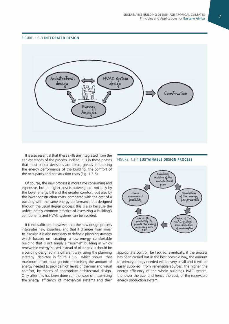
The energy expert must have an in-depth knowledge of building physics; he must be able to interact with the architect and with the mechanical engineer; he must not only be capable of managing rules of thumb, but he must also be able to use sophisticated simulation tools for evaluating the energy performance of the building, thermal comfort, daylighting, natural ventilation and all the passive means of reducing energy demands. From these
evaluations the energy expert derives recommendations for the architect and the mechanical engineer who, in turn, modify their design choices accordingly, proposing new solutions that have to be re-evaluated. This circular process is repeated until a satisfactory solution is reached, taking into account not only energy, but also aesthetics, functionality and economy (Fig. 1.3-4).
SUSTAINABLE BUILDING DESIGN FOR TROPICAL CLIMATES Principles and Applications for Eastern Africa 7
Figure. 1.3-3 Integrated desIgn
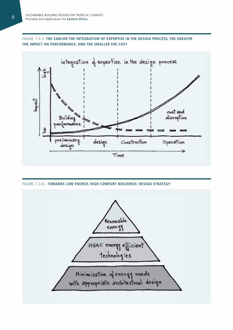
It is also essential that these skills are integrated from the earliest stages of the process. Indeed, it is in these phases that most critical decisions are taken, greatly influencing the energy performance of the building, the comfort of the occupants and construction costs (Fig. 1.3-5).
Of course, the new process is more time consuming and expensive, but its higher cost is outweighed not only by the lower energy bill and the greater comfort, but also by the lower construction costs, compared with the cost of a building with the same energy performance but designed through the usual design process; this is also because the unfortunately common practice of oversizing a building’s components and HVAC systems can be avoided.
It is not sufficient, however, that the new design process integrates new expertise, and that it changes from linear to circular. It is also necessary to define a planning strategy which focuses on creating a low energy, comfortable building that is not simply a “normal” building in which renewable energy is used instead of oil or gas. It should be a building designed in a different way, using the planning strategy depicted in figure 1.3-6. which shows that maximum effort must go into minimising the amount of energy needed to provide high levels of thermal and visual comfort, by means of appropriate architectural design. Only after this has been done can the issue of maximising the energy efficiency of mechanical systems and their
appropriate control be tackled. Eventually, if the process has been carried out in the best possible way, the amount of primary energy needed will be very small and it will be easily supplied from renewable sources: the higher the energy efficiency of the whole building+HVAC system, the lower the size, and hence the cost, of the renewable energy production system.
Figure. 1.3-4 sustaInable desIgn process
SUSTAINABLE BUILDING DESIGN FOR TROPICAL CLIMATES Principles and Applications for Eastern Africa8
Figure. 1.3-5 the earlIer the IntegratIon of expertIse In the desIgn process, the greater the Impact on performance, and the smaller the cost
Figure. 1.3-6 – toWards loW energy, hIgh comfort buIldIngs: desIgn strategy
SUSTAINABLE BUILDING DESIGN FOR TROPICAL CLIMATES Principles and Applications for Eastern Africa 9
1.4 consTrucTIon maTerIals
About 40% of the raw materials and energy produced worldwide are used in the building sector.
The production of cement, steel, glass, aluminium and baked bricks, which are the basic building materials for most modern constructions, have very high environmental impacts, consume the most energy and cause the majority of the GHG emissions in the construction sector5 because their production requires the processing of mined raw materials at a very high temperature.
The cement industry is responsible for ~1/4 of the annual worldwide CO2 emissions from fossil fuels6.
The production of iron and steel, which is also used in reinforced concrete, is responsible for more than 4% of the total energy use worldwide and the related GHG emissions7.
The production of glass also causes immense GHG emissions because its production is very heat energy intensive, but glass can also help to save and gain energy if it is utilised in an appropriate way, not according to the present architectural fashion. Intelligent use of the available natural materials such as inorganic materials (e.g. natural stones and clay) and especially the utilisation of building materials made out of organic raw materials, produced from biomass which is renewable, can lead to a significant reduction in the GHG emissions and the environmental impacts caused by the production of building materials.
Developing countries need not go through the same process of development as that followed by developed countries. Instead these countries can choose to base all future development on the principles of sustainability8.
Sustainable construction practices in the developing world have to be achieved as soon as possible, because the building and construction sector in these countries is growing very fast. Additionally the shift towards sustainability in the construction sector may play an important role in shifting the economic structure towards sustainability and in improving the quality of life of the poor. Innovations in sustainable building materials, construction methods and architectural design can be based on traditional knowledge and practice, which are in general relatively well adapted to local climates (see chapter 4) and use locally available materials.
5 CIB, UNEP – IETC; “Agenda 21 for Sustainable Construction in Developing Countries”; South Africa 2002
6 UNEP DTIE IETC, Basic Principles and Guidelines in Design and Construction to Reduce Greenhouse Gases in Buildings
7 World Resources 2000-2001, http://www.wri.org8 C. du Plessis, Agenda 21 for Sustainable Construction in Developing Countries,
CSIR Building and Construction Technology, 2002 - http://www.cidb.org.za/documents/kc/external_publications/ext_pubs_a21_sustainable_construction.pdf
Development also has to be adapted to specific ecological, economic and social conditions in order to meet present and future needs and requirements. However, the majority of people want to use “modern” and “fashionable” building materials, such as metal sheets as roofing material and cement blocks and cement plaster as wall building materials, not because the indoor climate is better than in houses built with traditional materials and methods, but because it looks “modern”. The utilisation of these techniques in cities requires rethinking; politicians, investors, city planners and architects in particular should abandon the vision of the architecture and town planning of the 20th century, which has proved to be unsustainable.
1.5 archITecTure In TropIcal clImaTes
In developed countries, which are mostly located in cold climates, the main cause of energy consumption in buildings is heating, but the efforts to curb this consumption are being more and more frustrated by the growth of air conditioning. In EAC climates the challenge is only the latter9. The growth in energy consumption for air conditioning is due to the need to live in more comfortable spaces, and this is justified, but it is exacerbated by two other factors: inappropriate architecture and the wrong approach to thermal comfort. The former can be offset by following the principles of sustainable building design, but the latter requires a behavioural change. Temperatures in North American air conditioned buildings, and unfortunately also in buildings in most developing countries, are far below the physiological requirements for thermal comfort. Temperatures set below 24 °C are common in all commercial buildings, often requiring occupants to wear a pullover or a jacket and – in hotels – to use blankets. This does not happen in Europe, where temperatures in air-conditioned spaces do not usually fall below 25 °C.
In tropical climates, therefore, the challenge for containing the growth of energy consumption in buildings is not limited to a change in the mentality of architects and builders, but also in the mentality of final users.
The combination of both a well-designed building, where solar gains are controlled and natural ventilation is fully exploited, , along with a change in comfort principles, can dramatically reduce energy consumption for air conditioning and provide very good conditions of comfort.
Sustainable architecture in tropical climates is a still an unexplored field, and it is an extraordinary challenge for architects, who should be willing to integrate basic information about building physics and aesthetics, and to
9 Some increase of energy consumption for heating can be expected in high upland climate, but is absolutely negligible compared to that of air conditioning in all other climates.
SUSTAINABLE BUILDING DESIGN FOR TROPICAL CLIMATES Principles and Applications for Eastern Africa10
abandon the approach, (now old and out-dated) which imitates the architecture of developed countries.
1.6 a new energy sysTem for cITIesWhen, about two centuries ago, the first gas networks
were built in our cities, the basis for the present urban energy system was set up. At that time coal was the only fossil energy source used. A little more than a century ago urban electric grids appeared, and coal was slowly replaced by oil and natural gas. Wood and charcoal soon disappeared; horses were substituted by cars and public transportation systems started to develop. At the beginning of the last century the main cities of the western world were provided with a sewage system, a water network and a solid waste collection system. There was no more hard work carrying water from the fountains, there were no more epidemics, instead there were comfortable interiors with heating, cooling and electric lighting, an easier life at home with domestic appliances, and fast mobility. The quality of life was revolutionised thanks to cheap fossil fuels and to the technologies fed by them.
Cities slowly changed, and learnt to metabolise fossil fuels, building up an urban energy system and an overall metabolic system that left no room for recycling: the saturation of the environment with wastes was not an issue. At the end of the process a new organism, the modern city, was born, fit for an environment that was assumed to be an infinite source and an infinite sink. The present urban energy system is designed on this assumption, and for this reason, it is incompatible with the extensive use of renewable energy sources; in the same way you cannot feed a lion with vegetables, it needs meat. Our task is to transform, with some sort of genetic engineering, our carnivore – the fossil energy based city – into a herbivore, the renewable energy based city. Unfortunately we do not have two centuries in front of us; we must do it in less than forty years. Forty years to
redesign the energy systems of our existing settlements and less than twenty to learn how to design all the new ones in a different way. In the 1970s – after the first oil shock – a few pioneers began to introduce the energy issue into architectural design. Guidelines for low energy building design were implemented, and now they are becoming compulsory practice in the European Union and in some other countries .
Now is the time to introduce the energy issue into urban design, since the most significant energy savings can be obtained on this scale by redesigning the overall energy system.
This implies changing the priorities in the formal design of urban layout and in the organization of urban functions, but this is not all.. The Distributed Energy Resources (DER) approach must be introduced. This consists of many small scale interconnected energy production and consumption units instead of a few large production plants.
It is the only way to design new settlements (or re-design existing ones) that are capable of relying mostly on renewable energy sources. It also implies an evolutionary jump towards a far more “intelligent” urban energy system, because a distributed control system is also needed – made possible by the present developments in the information and communication technologies. A change in the energy paradigm is the only chance we have of coping with the present world trend, which is leading to either economic or ecological catastrophe, or both.
It is not an easy task, because it is a technological change that implies a cultural change. The culture of architects and city planners, of citizens, of entrepreneurs, of city managers and politicians has to change.
SUSTAINABLE BUILDING DESIGN FOR TROPICAL CLIMATES Principles and Applications for Eastern Africa 11
clImaTes and buIldIng desIgn02
2.1 clImaTIc parameTers
Weather is the state of the atmospheric environment over a brief period of time in a specific place. Integrated weather conditions over several years are referred to as climate.
Different terms are used depending on the size of the geographical area considered. We refer to macroclimate for a large territory, meso-climate for a medium-size area, local climate and microclimate for a small area at the level of the individual or of a single confined space.
Local climate is generally related to an area ranging from a few square meters to a few hectares. For example, it can apply to the side of a hill, a valley or a portion of the built area, and is characterized by more or less marked changes in temperature, relative humidity, wind, sunshine, etc., due to the particular nature of the topography, urban morphology, orientation, nature of materials, proximity to water, presence or absence of vegetation, etc.
The main climatic parameters influencing the energy performance of a building are:
• solar radiation;
• air temperature;
• relative humidity;
• wind.
Solar radiation is the main driver of climate, since it influences temperature and gives rise to regional winds. The temperature at a given latitude depends on the angle of incidence of solar rays to the ground: it is highest at the equator and lowest at the poles. The higher the angle of incidence (and thus the lower the latitude) the more energy reaches the ground and the higher the air temperature.
Regional winds derive from the difference in air temperature (and thus pressure) between northern and equatorial latitudes.
2.1.1 solar geomeTry
The earth moves along an elliptical orbital trajectory around the sun in a little more than 365 days, and also rotates around its own axis, which is inclined by about 67° to the plane of the orbit. It takes about 24 hours to perform a complete 360° revolution (Fig. 2.1-1). The earth’s position during its own rotation may be defined by the hour angle ω, which is the angular distance between the meridian of the observer and the meridian whose plane contains the sun. This angle varies 15 degrees per hour, is zero at noon and has positive values in the morning and negative values in the afternoon (for example: at 10 a.m. ω = +30°; at 13 p.m. ω = -15°)
Seasonal climate change is the result of the different ways in which the sun’s rays hit the various regions of the earth during the year. This is due to the inclination of the plane of the equator, thus to the inclination of earth’s axis. The tilt of earth’s axis with respect to the plane of the orbit is constant but the angle formed between the line joining the centre of the earth with the centre of the sun and the equatorial plane changes day by day, or, it is better to say, instant by instant. This angle is called the solar declination δ, is equal to zero at the spring and autumn equinoxes, and is +23.45° at the summer solstice and -23.45° at the winter solstice.
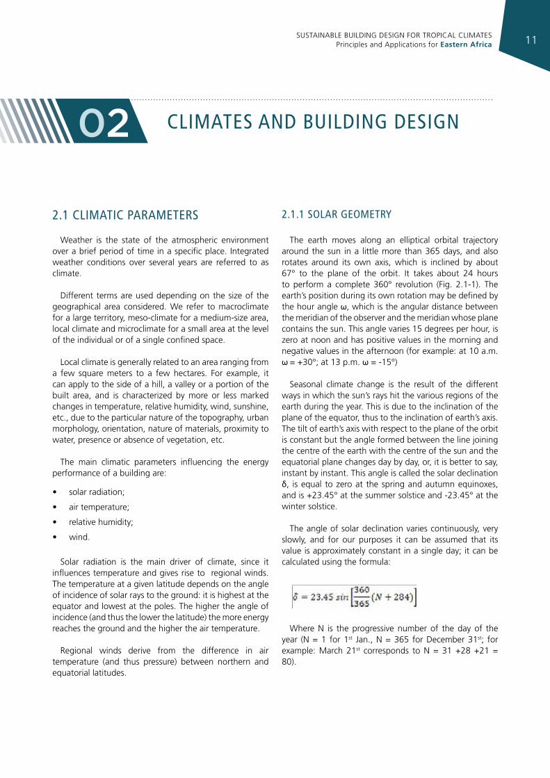
The angle of solar declination varies continuously, very slowly, and for our purposes it can be assumed that its value is approximately constant in a single day; it can be calculated using the formula:
Where N is the progressive number of the day of the year (N = 1 for 1st Jan., N = 365 for December 31st; for example: March 21st corresponds to N = 31 +28 +21 = 80).
SUSTAINABLE BUILDING DESIGN FOR TROPICAL CLIMATES Principles and Applications for Eastern Africa12
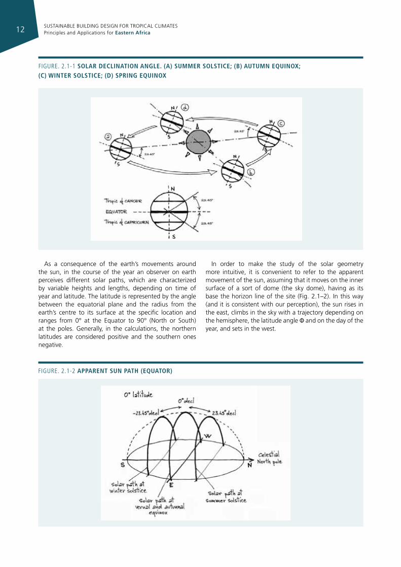
Figure. 2.1-1 solar declInatIon angle. (a) summer solstIce; (b) autumn equInox; (c) WInter solstIce; (d) sprIng equInox
As a consequence of the earth’s movements around the sun, in the course of the year an observer on earth perceives different solar paths, which are characterized by variable heights and lengths, depending on time of year and latitude. The latitude is represented by the angle between the equatorial plane and the radius from the earth’s centre to its surface at the specific location and ranges from 0° at the Equator to 90° (North or South) at the poles. Generally, in the calculations, the northern latitudes are considered positive and the southern ones negative.
In order to make the study of the solar geometry more intuitive, it is convenient to refer to the apparent movement of the sun, assuming that it moves on the inner surface of a sort of dome (the sky dome), having as its base the horizon line of the site (Fig. 2.1–2). In this way (and it is consistent with our perception), the sun rises in the east, climbs in the sky with a trajectory depending on the hemisphere, the latitude angle Φ and on the day of the year, and sets in the west.
Figure. 2.1-2 apparent sun path (equator)
SUSTAINABLE BUILDING DESIGN FOR TROPICAL CLIMATES Principles and Applications for Eastern Africa 13
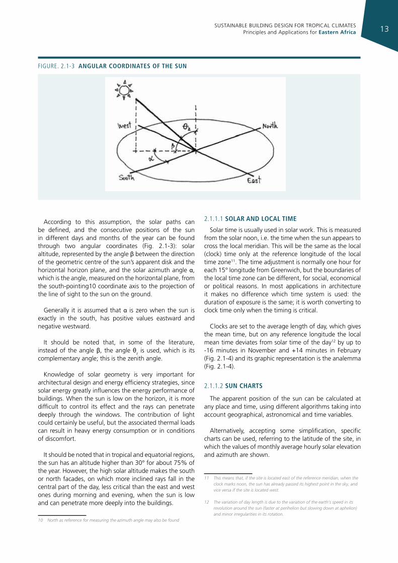
According to this assumption, the solar paths can be defined, and the consecutive positions of the sun in different days and months of the year can be found through two angular coordinates (Fig. 2.1-3): solar altitude, represented by the angle β between the direction of the geometric centre of the sun’s apparent disk and the horizontal horizon plane, and the solar azimuth angle α, which is the angle, measured on the horizontal plane, from the south-pointing10 coordinate axis to the projection of the line of sight to the sun on the ground.
Generally it is assumed that α is zero when the sun is exactly in the south, has positive values eastward and negative westward.
It should be noted that, in some of the literature, instead of the angle β, the angle θz is used, which is its complementary angle; this is the zenith angle.
Knowledge of solar geometry is very important for architectural design and energy efficiency strategies, since solar energy greatly influences the energy performance of buildings. When the sun is low on the horizon, it is more difficult to control its effect and the rays can penetrate deeply through the windows. The contribution of light could certainly be useful, but the associated thermal loads can result in heavy energy consumption or in conditions of discomfort.
It should be noted that in tropical and equatorial regions, the sun has an altitude higher than 30° for about 75% of the year. However, the high solar altitude makes the south or north facades, on which more inclined rays fall in the central part of the day, less critical than the east and west ones during morning and evening, when the sun is low and can penetrate more deeply into the buildings.
10 North as reference for measuring the azimuth angle may also be found
2.1.1.1 solar and local tIme
Solar time is usually used in solar work. This is measured from the solar noon, i.e. the time when the sun appears to cross the local meridian. This will be the same as the local (clock) time only at the reference longitude of the local time zone11. The time adjustment is normally one hour for each 15° longitude from Greenwich, but the boundaries of the local time zone can be different, for social, economical or political reasons. In most applications in architecture it makes no difference which time system is used: the duration of exposure is the same; it is worth converting to clock time only when the timing is critical.
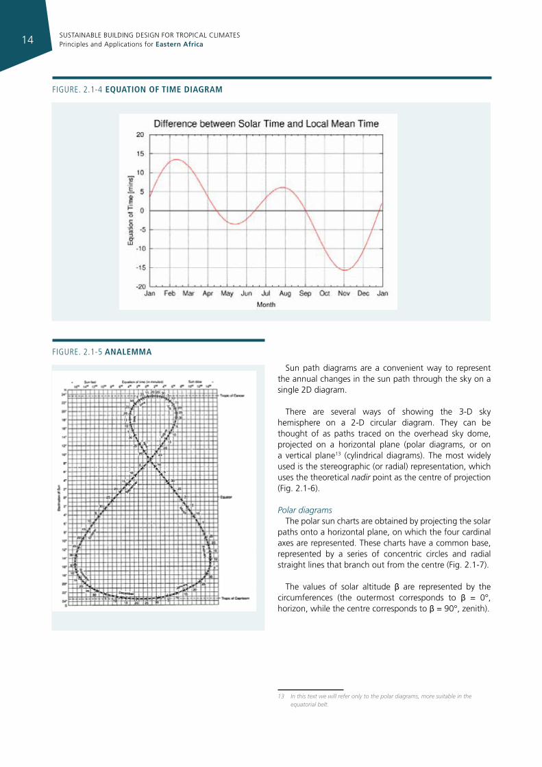
Clocks are set to the average length of day, which gives the mean time, but on any reference longitude the local mean time deviates from solar time of the day12 by up to -16 minutes in November and +14 minutes in February (Fig. 2.1-4) and its graphic representation is the analemma (Fig. 2.1-4).
2.1.1.2 sun charts
The apparent position of the sun can be calculated at any place and time, using different algorithms taking into account geographical, astronomical and time variables.
Alternatively, accepting some simplification, specific charts can be used, referring to the latitude of the site, in which the values of monthly average hourly solar elevation and azimuth are shown.
11 This means that, if the site is located east of the reference meridian, when the clock marks noon, the sun has already passed its highest point in the sky, and vice versa if the site is located west.
12 The variation of day length is due to the variation of the earth’s speed in its revolution around the sun (faster at perihelion but slowing down at aphelion) and minor irregularities in its rotation.
Figure. 2.1-3 angular coordInates of the sun
SUSTAINABLE BUILDING DESIGN FOR TROPICAL CLIMATES Principles and Applications for Eastern Africa14
Figure. 2.1-4 equatIon of tIme dIagram
Figure. 2.1-5 analemma
Sun path diagrams are a convenient way to represent the annual changes in the sun path through the sky on a single 2D diagram.
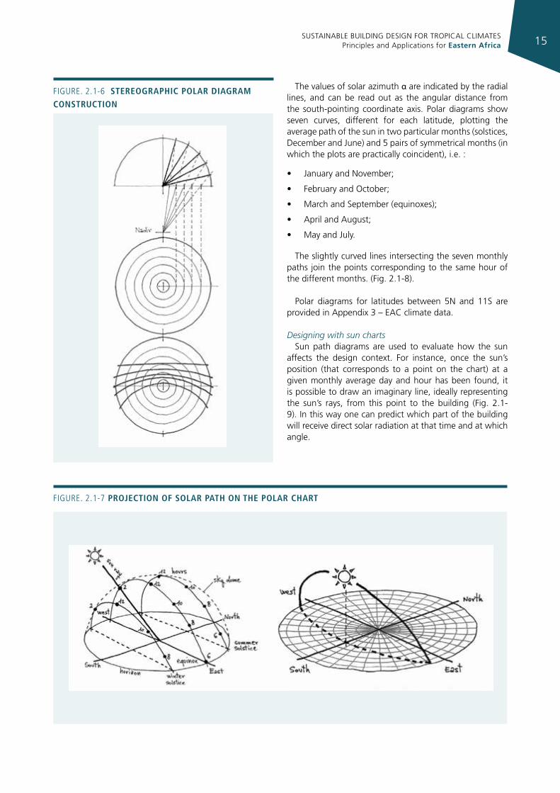
There are several ways of showing the 3-D sky hemisphere on a 2-D circular diagram. They can be thought of as paths traced on the overhead sky dome, projected on a horizontal plane (polar diagrams, or on a vertical plane13 (cylindrical diagrams). The most widely used is the stereographic (or radial) representation, which uses the theoretical nadir point as the centre of projection (Fig. 2.1-6).
Polar diagramsThe polar sun charts are obtained by projecting the solar
paths onto a horizontal plane, on which the four cardinal axes are represented. These charts have a common base, represented by a series of concentric circles and radial straight lines that branch out from the centre (Fig. 2.1-7).
The values of solar altitude β are represented by the circumferences (the outermost corresponds to β = 0°, horizon, while the centre corresponds to β = 90°, zenith).
13 In this text we will refer only to the polar diagrams, more suitable in the equatorial belt.
SUSTAINABLE BUILDING DESIGN FOR TROPICAL CLIMATES Principles and Applications for Eastern Africa 15
Figure. 2.1-6 stereographIc polar dIagram constructIon
Figure. 2.1-7 projectIon of solar path on the polar chart
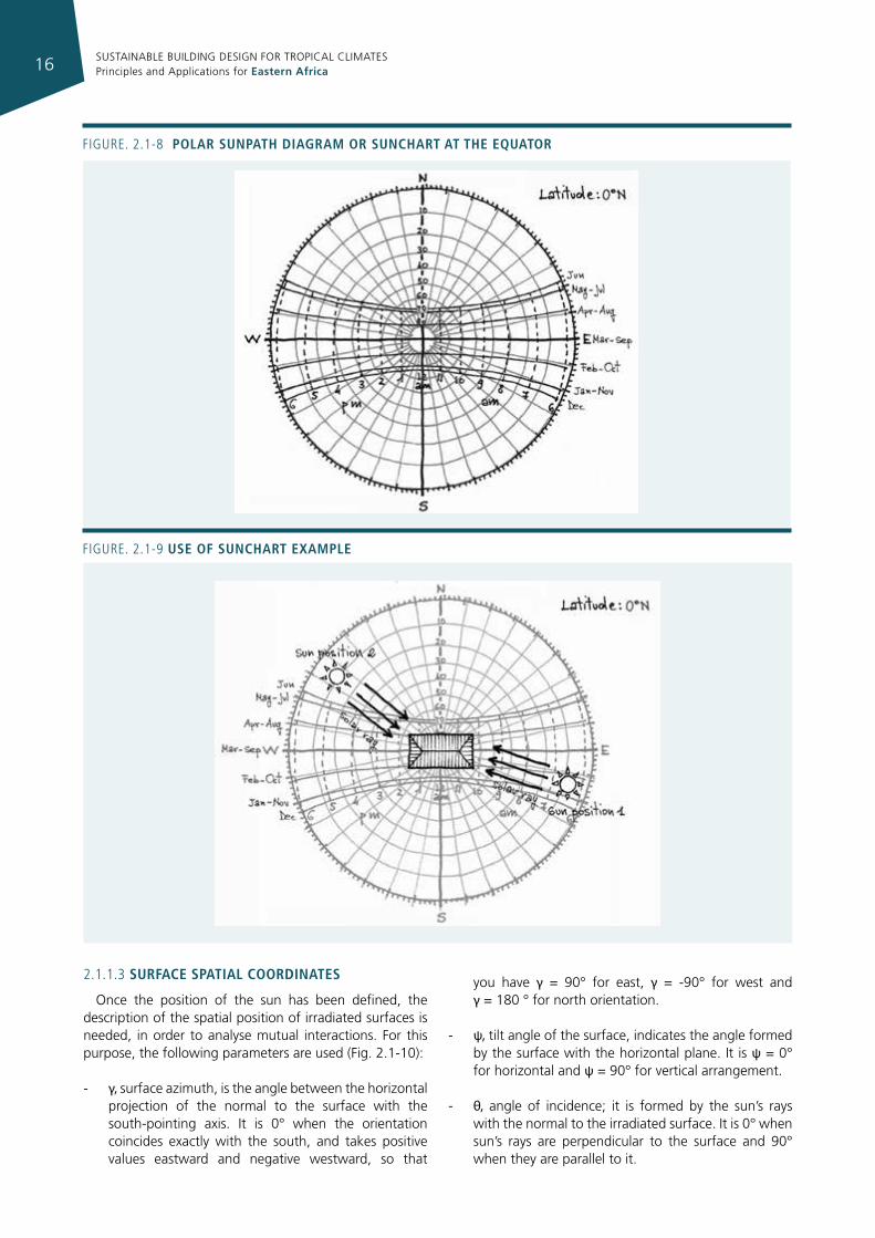
The values of solar azimuth α are indicated by the radial lines, and can be read out as the angular distance from the south-pointing coordinate axis. Polar diagrams show seven curves, different for each latitude, plotting the average path of the sun in two particular months (solstices, December and June) and 5 pairs of symmetrical months (in which the plots are practically coincident), i.e. :
• January and November;
• February and October;
• March and September (equinoxes);
• April and August;
• May and July.
The slightly curved lines intersecting the seven monthly paths join the points corresponding to the same hour of the different months. (Fig. 2.1-8).
Polar diagrams for latitudes between 5N and 11S are provided in Appendix 3 – EAC climate data.
Designing with sun chartsSun path diagrams are used to evaluate how the sun
affects the design context. For instance, once the sun’s position (that corresponds to a point on the chart) at a given monthly average day and hour has been found, it is possible to draw an imaginary line, ideally representing the sun’s rays, from this point to the building (Fig. 2.1-9). In this way one can predict which part of the building will receive direct solar radiation at that time and at which angle.
SUSTAINABLE BUILDING DESIGN FOR TROPICAL CLIMATES Principles and Applications for Eastern Africa16
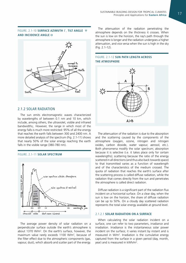
2.1.1.3 surface spatIal coordInates
Once the position of the sun has been defined, the description of the spatial position of irradiated surfaces is needed, in order to analyse mutual interactions. For this purpose, the following parameters are used (Fig. 2.1-10):
- γ, surface azimuth, is the angle between the horizontal projection of the normal to the surface with the south-pointing axis. It is 0° when the orientation coincides exactly with the south, and takes positive values eastward and negative westward, so that
Figure. 2.1-8 polar sunpath dIagram or sunchart at the equator
Figure. 2.1-9 use of sunchart example
you have γ = 90° for east, γ = -90° for west and γ = 180 ° for north orientation.
- ψ, tilt angle of the surface, indicates the angle formed by the surface with the horizontal plane. It is ψ = 0° for horizontal and ψ = 90° for vertical arrangement.
- θ, angle of incidence; it is formed by the sun’s rays with the normal to the irradiated surface. It is 0° when sun’s rays are perpendicular to the surface and 90° when they are parallel to it.
SUSTAINABLE BUILDING DESIGN FOR TROPICAL CLIMATES Principles and Applications for Eastern Africa 17
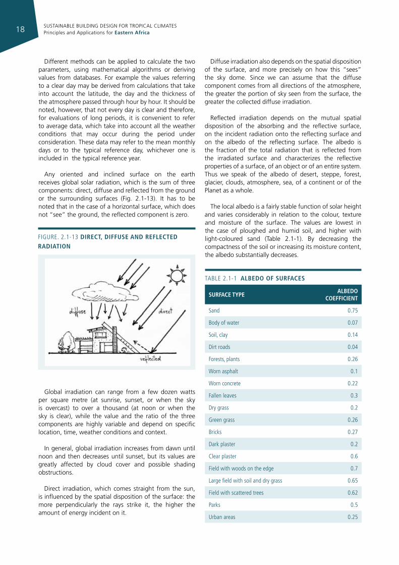
The attenuation of the radiation penetrating the atmosphere depends on the thickness it crosses. When the sun is low on the horizon, the ray’s path through the atmosphere is longer and the radiation undergoes a higher attenuation, and vice versa when the sun is high in the sky (Fig. 2.1-12).
The attenuation of the radiation is due to the absorption and the scattering caused by the components of the atmosphere (oxygen, ozone, nitrogen and nitrogen oxides, carbon dioxide, water vapour, aerosol, etc.). Both phenomena modify the solar spectrum; absorption because it is selective (i.e. it takes place only for certain wavelengths); scattering because the ratio of the energy scattered in all directions (and thus also back towards space) to that transmitted varies as a function of wavelength and of the characteristics of the medium crossed. The quota of radiation that reaches the earth’s surface after the scattering process is called diffuse radiation, while the radiation that comes directly from the sun and penetrates the atmosphere is called direct radiation.
Diffuse radiation is a significant part of the radiation flux incident on a horizontal surface. On a clear day, when the sun is low on the horizon, the share of diffuse radiation can be up to 50%. On a cloudy day scattered radiation represents the total solar energy available at ground level.
2.1.2.1 solar radIatIon on a surface
When calculating the solar radiation incident on a surface, one can refer to two parameters, irradiance and irradiation. Irradiance is the instantaneous solar power incident on the surface; it varies instant by instant and is measured in W/m2. Irradiation is the cumulative energy captured from the surface in a given period (day, month, year) and is measured in kWh/m2.
2.1.2 solar radIaTIon
The sun emits electromagnetic waves characterized by wavelengths of between 0.1 nm and 10 km, which include, among others, the ultraviolet, visible and infrared bandwidths;. However, the range in which most of the energy falls is much more restricted: 95% of all the energy that reaches the earth falls between 300 and 2400 nm. A more detailed analysis of the spectrum (Fig. 2.1-11) shows that nearly 50% of the solar energy reaching the earth falls in the visible range (380-780 nm).
The average power density of solar radiation on a perpendicular surface outside the earth’s atmosphere is about 1370 W/m2. On the earth’s surface, however, the maximum value rarely exceeds 1100 W/m2, because of the filter effect due to the atmospheric components (gas, vapour, dust), which absorb and scatter part of the energy.
Figure. 2.1-10 surface azImuth γ, tIlt angle ψ
and IncIdence angle θ
Figure. 2.1-11 solar spectrum
Figure. 2.1-12 sun path length across the atmosphere
SUSTAINABLE BUILDING DESIGN FOR TROPICAL CLIMATES Principles and Applications for Eastern Africa18
Different methods can be applied to calculate the two parameters, using mathematical algorithms or deriving values from databases. For example the values referring to a clear day may be derived from calculations that take into account the latitude, the day and the thickness of the atmosphere passed through hour by hour. It should be noted, however, that not every day is clear and therefore, for evaluations of long periods, it is convenient to refer to average data, which take into account all the weather conditions that may occur during the period under consideration. These data may refer to the mean monthly days or to the typical reference day, whichever one is included in the typical reference year.
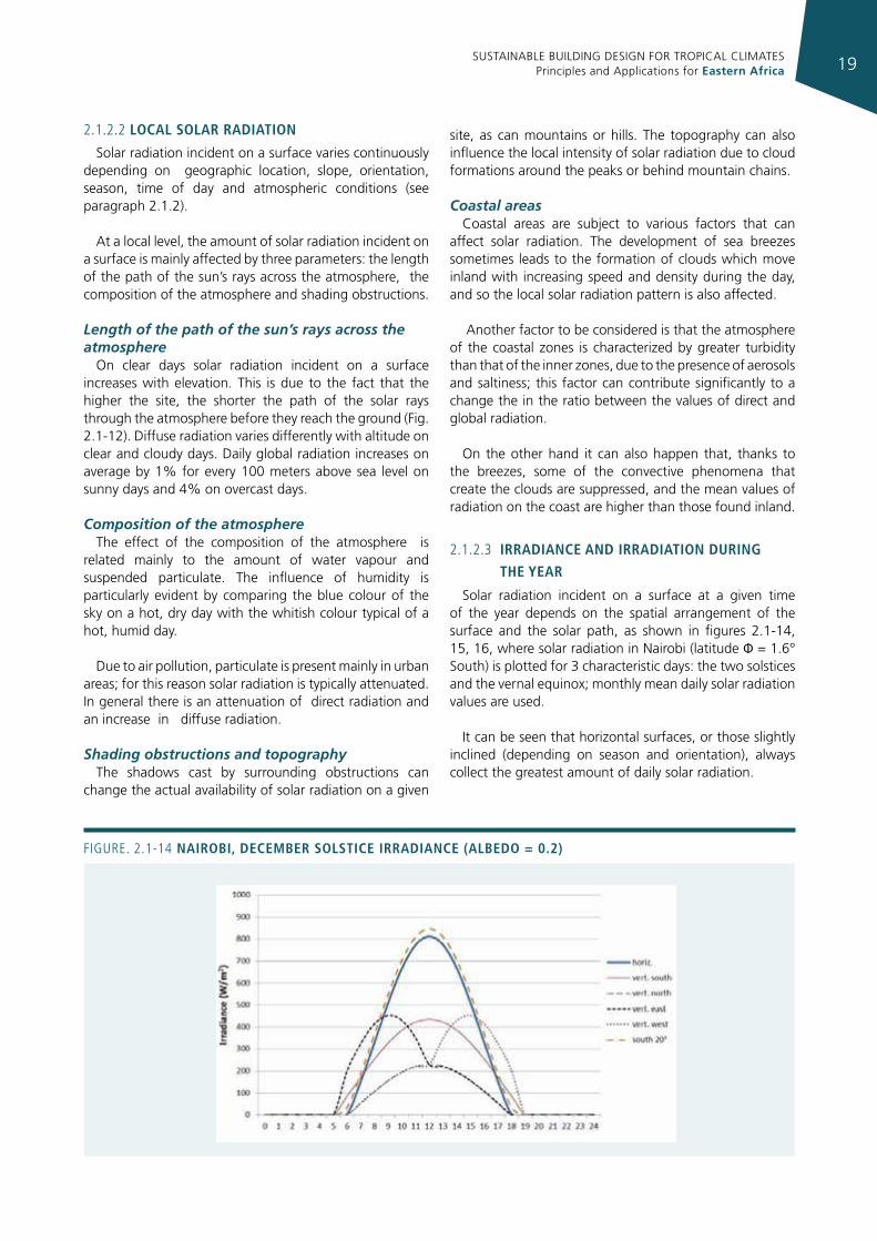
Any oriented and inclined surface on the earth receives global solar radiation, which is the sum of three components: direct, diffuse and reflected from the ground or the surrounding surfaces (Fig. 2.1-13). It has to be noted that in the case of a horizontal surface, which does not “see” the ground, the reflected component is zero.
Global irradiation can range from a few dozen watts per square metre (at sunrise, sunset, or when the sky is overcast) to over a thousand (at noon or when the sky is clear), while the value and the ratio of the three components are highly variable and depend on specific location, time, weather conditions and context.
In general, global irradiation increases from dawn until noon and then decreases until sunset, but its values are greatly affected by cloud cover and possible shading obstructions.
Direct irradiation, which comes straight from the sun, is influenced by the spatial disposition of the surface: the more perpendicularly the rays strike it, the higher the amount of energy incident on it.
Diffuse irradiation also depends on the spatial disposition of the surface, and more precisely on how this “sees” the sky dome. Since we can assume that the diffuse component comes from all directions of the atmosphere, the greater the portion of sky seen from the surface, the greater the collected diffuse irradiation.
Reflected irradiation depends on the mutual spatial disposition of the absorbing and the reflective surface, on the incident radiation onto the reflecting surface and on the albedo of the reflecting surface. The albedo is the fraction of the total radiation that is reflected from the irradiated surface and characterizes the reflective properties of a surface, of an object or of an entire system. Thus we speak of the albedo of desert, steppe, forest, glacier, clouds, atmosphere, sea, of a continent or of the Planet as a whole.
The local albedo is a fairly stable function of solar height and varies considerably in relation to the colour, texture and moisture of the surface. The values are lowest in the case of ploughed and humid soil, and higher with light-coloured sand (Table 2.1-1). By decreasing the compactness of the soil or increasing its moisture content, the albedo substantially decreases.
surface typealbedo
coeffIcIent
Sand 0.75
Body of water 0.07
Soil, clay 0.14
Dirt roads 0.04
Forests, plants 0.26
Worn asphalt 0.1
Worn concrete 0.22
Fallen leaves 0.3
Dry grass 0.2
green grass 0.26
Bricks 0.27
Dark plaster 0.2
Clear plaster 0.6
Field with woods on the edge 0.7
Large field with soil and dry grass 0.65
Field with scattered trees 0.62
Parks 0.5
urban areas 0.25
TABLe 2.1-1 albedo of surfaces
Figure. 2.1-13 dIrect, dIffuse and reflected radIatIon
SUSTAINABLE BUILDING DESIGN FOR TROPICAL CLIMATES Principles and Applications for Eastern Africa 19
2.1.2.2 local solar radIatIon
Solar radiation incident on a surface varies continuously depending on geographic location, slope, orientation, season, time of day and atmospheric conditions (see paragraph 2.1.2).
At a local level, the amount of solar radiation incident on a surface is mainly affected by three parameters: the length of the path of the sun’s rays across the atmosphere, the composition of the atmosphere and shading obstructions.
Length of the path of the sun’s rays across the atmosphere
On clear days solar radiation incident on a surface increases with elevation. This is due to the fact that the higher the site, the shorter the path of the solar rays through the atmosphere before they reach the ground (Fig. 2.1-12). Diffuse radiation varies differently with altitude on clear and cloudy days. Daily global radiation increases on average by 1% for every 100 meters above sea level on sunny days and 4% on overcast days.
Composition of the atmosphereThe effect of the composition of the atmosphere is
related mainly to the amount of water vapour and suspended particulate. The influence of humidity is particularly evident by comparing the blue colour of the sky on a hot, dry day with the whitish colour typical of a hot, humid day.
Due to air pollution, particulate is present mainly in urban areas; for this reason solar radiation is typically attenuated. In general there is an attenuation of direct radiation and an increase in diffuse radiation.
Shading obstructions and topographyThe shadows cast by surrounding obstructions can
change the actual availability of solar radiation on a given
site, as can mountains or hills. The topography can also influence the local intensity of solar radiation due to cloud formations around the peaks or behind mountain chains.
Coastal areasCoastal areas are subject to various factors that can
affect solar radiation. The development of sea breezes sometimes leads to the formation of clouds which move inland with increasing speed and density during the day, and so the local solar radiation pattern is also affected.
Another factor to be considered is that the atmosphere of the coastal zones is characterized by greater turbidity than that of the inner zones, due to the presence of aerosols and saltiness; this factor can contribute significantly to a change the in the ratio between the values of direct and global radiation.
On the other hand it can also happen that, thanks to the breezes, some of the convective phenomena that create the clouds are suppressed, and the mean values of radiation on the coast are higher than those found inland.
2.1.2.3 IrradIance and IrradIatIon durIng
the year
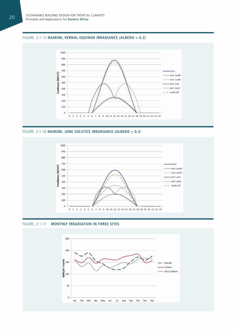
Solar radiation incident on a surface at a given time of the year depends on the spatial arrangement of the surface and the solar path, as shown in figures 2.1-14, 15, 16, where solar radiation in Nairobi (latitude Φ = 1.6° South) is plotted for 3 characteristic days: the two solstices and the vernal equinox; monthly mean daily solar radiation values are used.
It can be seen that horizontal surfaces, or those slightly inclined (depending on season and orientation), always collect the greatest amount of daily solar radiation.
Figure. 2.1-14 naIrobI, december solstIce IrradIance (albedo = 0.2)
SUSTAINABLE BUILDING DESIGN FOR TROPICAL CLIMATES Principles and Applications for Eastern Africa20
Figure. 2.1-15 naIrobI, vernal equInox IrradIance (albedo = 0.2)
Figure. 2.1-16 naIrobI, june solstIce IrradIance (albedo = 0.2)
Figure. 2.1-17 monthly IrradIatIon In three sItes
SUSTAINABLE BUILDING DESIGN FOR TROPICAL CLIMATES Principles and Applications for Eastern Africa 21
Vertical surfaces display great variability during the day and the year. East-facing surfaces collect more radiation in the morning. After midday they are hit only by diffuse radiation, because they don’t “see” the sun directly any more. West-facing surfaces, on the other hand, are more radiated in the afternoon. Vertical north and south-facing surfaces are constantly exposed to or hidden from direct solar radiation, depending on the season (the sun travelling in the northern or in the southern quadrant).
The final graph (Fig. 2.1-17) shows the overall trend of monthly irradiation on a horizontal surface for three locations: Nairobi (Φ: 1.6° South, upland climate), Dar es Salaam (Φ: 6.8° South, hot-humid climate) and Lodwar (Φ: 3.12° North, hot-arid climate).
As can be seen, values are contained in a range between 120 and 180 kWh/m2 per month, where the oscillations depend on the season and the specific climatic context.
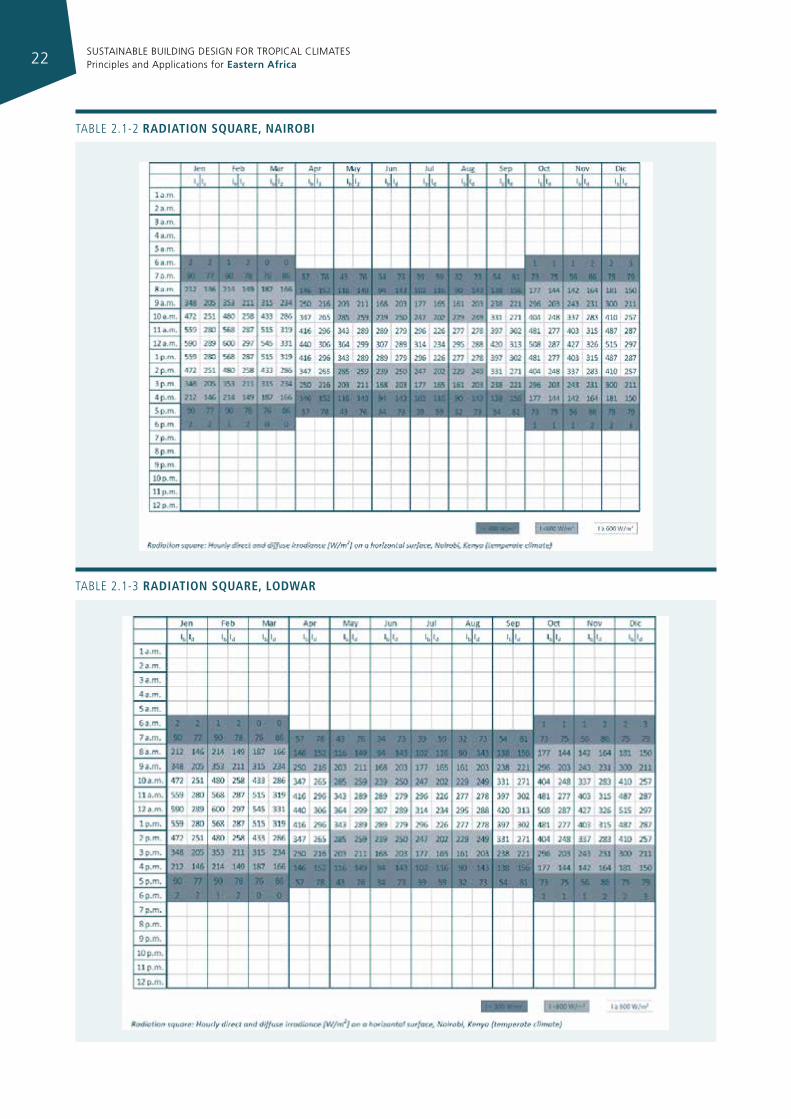
Note that Lodwar, with a less cloudy climate, is characterized by higher solar radiation values during the summer period.
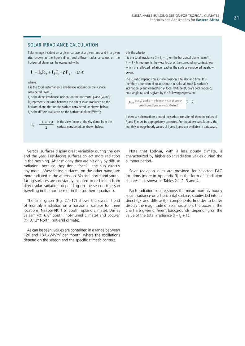
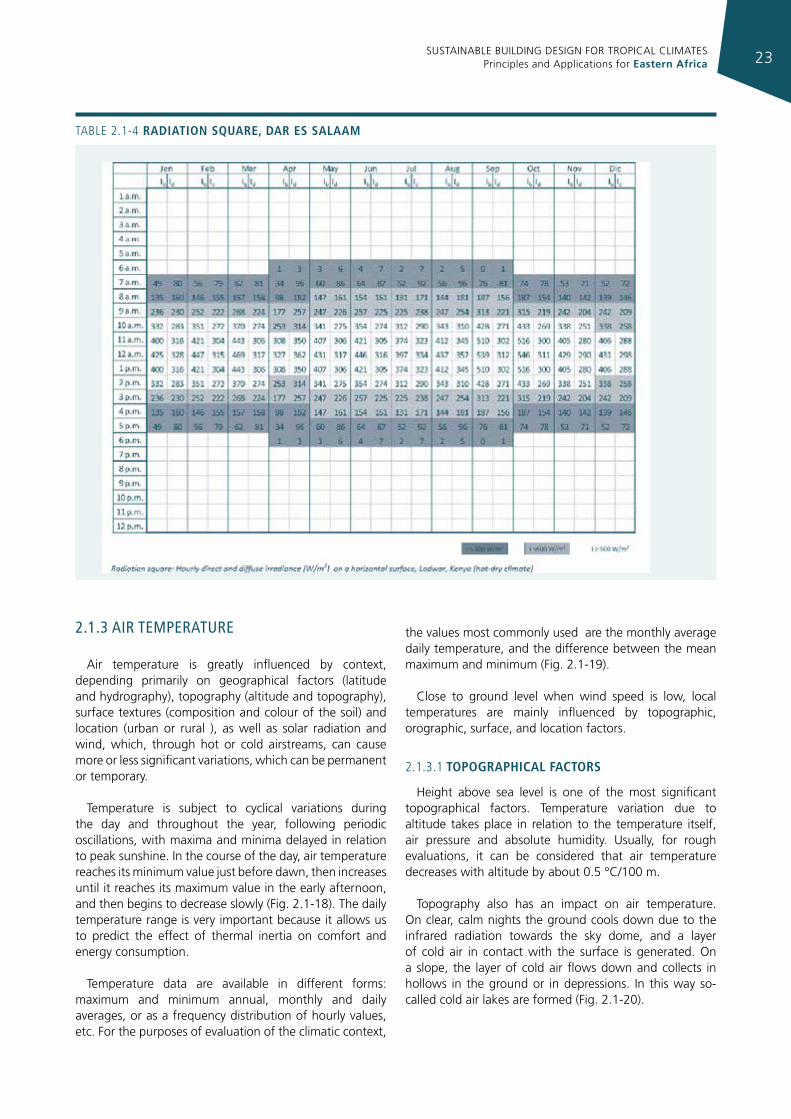
Solar radiation data are provided for selected EAC locations (more in Appendix 3) in the form of “radiation squares”, as shown in Tables 2.1-2, 3 and 4.
Each radiation square shows the mean monthly hourly solar irradiance on a horizontal surface, subdivided into its direct (Ib) and diffuse (Id) components. In order to better display the magnitude of solar radiation, the boxes in the chart are given different backgrounds, depending on the value of the total irradiance (I = Ib + Id).
solar IrradIance calculaTIonSolar energy incident on a given surface at a given time and in a given site, known as the hourly direct and diffuse irradiance values on the horizontal plane, can be evaluated with:
(2.1-1)
where:it is the total instantaneous irradiance incident on the surface considered [W/m2];ib is the direct irradiance incident on the horizontal plane [W/m2]; rb represents the ratio between the direct solar irradiance on the horizontal and that on the surface considered, as shown below; id is the diffuse irradiance on the horizontal plane [W/m2];
is the view factor of the sky dome from the surface considered, as shown below;
ρ is the albedo;i is the total irradiance (i = ib + id) on the horizontal plane [W/m2]; Fc = 1 - Fs represents the view factor of the surrounding context, from which the reflected radiation reaches the surface considered, as shown below.
The rb ratio depends on surface position, site, day and time. it is therefore a function of solar azimuth α, solar altitude β, surface’s inclination ψ and orientation γ, local latitude Φ, day’s declination δ, hour angle ω, and is given by the following expression:
(2.1-2)
if there are obstructions around the surface considered, then the values of Fs and Fc must be appropriately corrected. For the above calculations, the monthly average hourly values of ib and id and are available in databases.
csdbbt IFFIRII ρ++=
2cos1Fs
ψ+=
SUSTAINABLE BUILDING DESIGN FOR TROPICAL CLIMATES Principles and Applications for Eastern Africa22
TABLe 2.1-2 radIatIon square, naIrobI
TABLe 2.1-3 radIatIon square, lodWar
SUSTAINABLE BUILDING DESIGN FOR TROPICAL CLIMATES Principles and Applications for Eastern Africa 23
TABLe 2.1-4 radIatIon square, dar es salaam
2.1.3 aIr TemperaTure
Air temperature is greatly influenced by context, depending primarily on geographical factors (latitude and hydrography), topography (altitude and topography), surface textures (composition and colour of the soil) and location (urban or rural ), as well as solar radiation and wind, which, through hot or cold airstreams, can cause more or less significant variations, which can be permanent or temporary.
Temperature is subject to cyclical variations during the day and throughout the year, following periodic oscillations, with maxima and minima delayed in relation to peak sunshine. In the course of the day, air temperature reaches its minimum value just before dawn, then increases until it reaches its maximum value in the early afternoon, and then begins to decrease slowly (Fig. 2.1-18). The daily temperature range is very important because it allows us to predict the effect of thermal inertia on comfort and energy consumption.
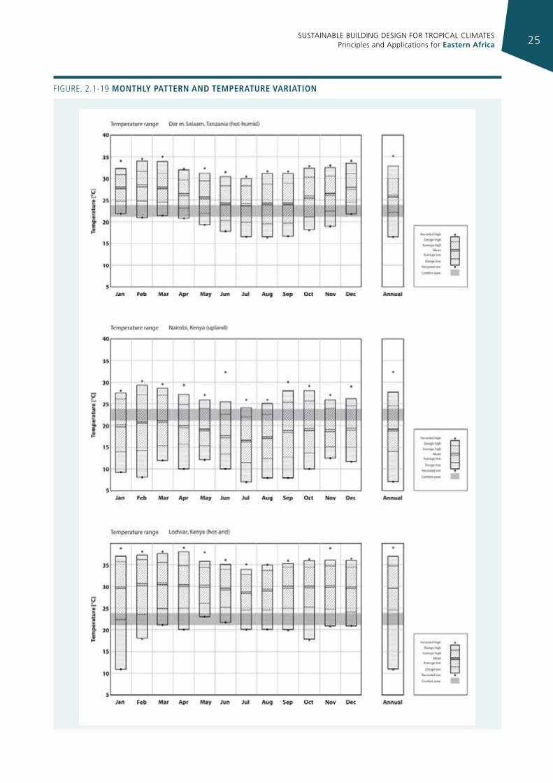
Temperature data are available in different forms: maximum and minimum annual, monthly and daily averages, or as a frequency distribution of hourly values, etc. For the purposes of evaluation of the climatic context,
the values most commonly used are the monthly average daily temperature, and the difference between the mean maximum and minimum (Fig. 2.1-19).
Close to ground level when wind speed is low, local temperatures are mainly influenced by topographic, orographic, surface, and location factors.
2.1.3.1 topographIcal factors
Height above sea level is one of the most significant topographical factors. Temperature variation due to altitude takes place in relation to the temperature itself, air pressure and absolute humidity. Usually, for rough evaluations, it can be considered that air temperature decreases with altitude by about 0.5 °C/100 m.
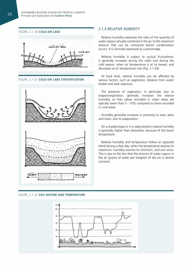
Topography also has an impact on air temperature. On clear, calm nights the ground cools down due to the infrared radiation towards the sky dome, and a layer of cold air in contact with the surface is generated. On a slope, the layer of cold air flows down and collects in hollows in the ground or in depressions. In this way so-called cold air lakes are formed (Fig. 2.1-20).

SUSTAINABLE BUILDING DESIGN FOR TROPICAL CLIMATES Principles and Applications for Eastern Africa24
Figure 2.1-18 temperature typIcal pattern (monthly average values)
Source: Climate Consultant
According to this phenomenon, a valley carved in a plateau should contain a deep cold air lake. This, however, does not happen because of the large size of the valley, which allows a certain amount of air circulation between the coldest area along the slope and the warmest above. The cold air lake, for this reason, is formed only at the bottom of valley (Fig. 2.1-21).
The maximum height of cold air lakes depends on the width of the valleys:
• narrow valleys: 3 m;
• average valleys: 8 m;
• wide valleys: 30 − 75 m.
2.1.3.2 surface factors
Generally, air temperature decreases or increases with soil temperature. The heat balance on the surface of the ground- and hence its temperature - is affected by its colour and texture (solar reflection coefficient, or albedo, see Table 2.1-1, paragraph 2.1.1.1), infrared emissivity and specific heat of the material the soil is made of, as shown in figure 2.1-22.
2.1.3.3 locatIon
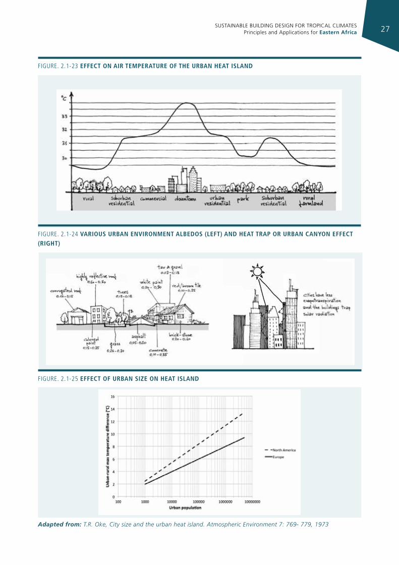
Since air temperature depends significantly on that of the ground or surrounding context, areas of urbanized land have – because of the their morphological configuration and the characteristics of the materials they are made of - a greater capacity to absorb solar radiation; to this has to be added the heat generated due to the heating and cooling of buildings and vehicular traffic. For these reasons, temperatures in urban areas are higher by a few degrees than in their rural surroundings (Fig. 2.1-23). This phenomenon, called the urban heat island, increases with the size of the city and towards its centre (which generally has higher building density).
In other words, the urban heat island occurs because the materials and morphology characterising the urban context act as a heat trap (Fig. 2.1-24). The heat island effect in warm to hot climates exacerbates the amount of energy used for cooling, but this can be reduced by using materials with high reflection coefficients, as well as by applying sunscreens (e.g. vegetation) in the most critical areas.
Urban size influences the heat island effect, as shown in figure 2.1-25, where the correlation between the maximum urban-rural temperature difference and urban size, expressed as urban population, is plotted for North American and European cities.
SUSTAINABLE BUILDING DESIGN FOR TROPICAL CLIMATES Principles and Applications for Eastern Africa 25
Figure. 2.1-19 monthly pattern and temperature varIatIon
SUSTAINABLE BUILDING DESIGN FOR TROPICAL CLIMATES Principles and Applications for Eastern Africa26
Figure. 2.1-20 cold aIr lake
Figure. 2.1-21 cold aIr lake stratIfIcatIon
2.1.4 relaTIve humIdITy
Relative humidity expresses the ratio of the quantity of water vapour actually contained in the air, to the maximum amount that can be contained before condensation occurs. It is normally expressed as a percentage.
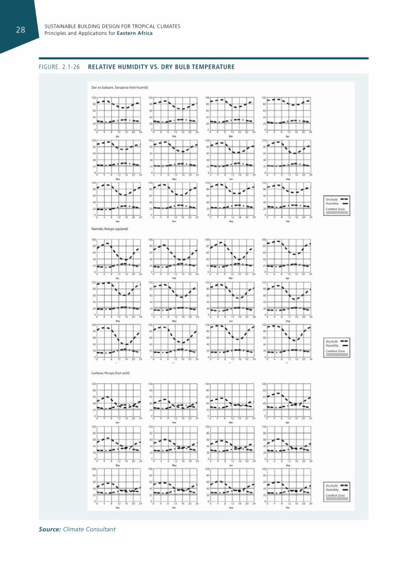
Relative humidity is subject to cyclical fluctuations; it generally increases during the night and during the cold season, when air temperature is at its lowest, and decreases as air temperature rises (Fig. 2.1-26).
At local level, relative humidity can be affected by various factors, such as vegetation, distance from water bodies and solar exposure.
The presence of vegetation, in particular, due to evapotranspiration, generally increases the relative humidity, so that values recorded in urban areas are typically lower than 5 - 10% compared to those recorded in rural areas.
Humidity generally increases in proximity to seas, lakes and rivers, due to evaporation.
On a shaded slope or in a valley bottom relative humidity is generally higher than elsewhere, because of the lower temperature.
Relative humidity and temperature follow an opposite trend during a clear day: when the temperature reaches its maximum, humidity reaches its minimum, and vice versa. This is due to the fact that the amount of water vapour in the air (grams of water per kilogram of dry air) is almost constant.
Figure. 2.1-22 soIl nature and temperature
SUSTAINABLE BUILDING DESIGN FOR TROPICAL CLIMATES Principles and Applications for Eastern Africa 27
Figure. 2.1-23 effect on aIr temperature of the urban heat Island
Figure. 2.1-24 varIous urban envIronment albedos (left) and heat trap or urban canyon effect (rIght)
Figure. 2.1-25 effect of urban sIze on heat Island
Adapted from: T.R. Oke, City size and the urban heat island. Atmospheric Environment 7: 769- 779, 1973
SUSTAINABLE BUILDING DESIGN FOR TROPICAL CLIMATES Principles and Applications for Eastern Africa28
Figure. 2.1-26 relatIve humIdIty vs. dry bulb temperature
Source: Climate Consultant
SUSTAINABLE BUILDING DESIGN FOR TROPICAL CLIMATES Principles and Applications for Eastern Africa 29
2.1.5 wInd
Wind is the movement of air masses caused by differences in atmospheric pressure related to land, water and air temperature gradients, which may occur at a macro-territorial level (between one geographical region and another) or on a local scale (waterfront, lakeside area, valleys, etc.).
In the first case we refer to regional winds, in the second to local winds.
The parameters which characterize wind are: speed, direction from which it flows and frequency.
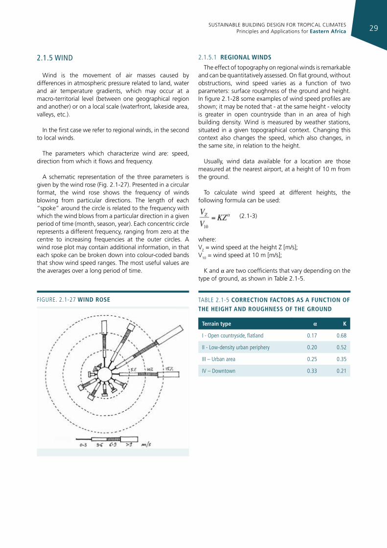
A schematic representation of the three parameters is given by the wind rose (Fig. 2.1-27). Presented in a circular format, the wind rose shows the frequency of winds blowing from particular directions. The length of each “spoke” around the circle is related to the frequency with which the wind blows from a particular direction in a given period of time (month, season, year). Each concentric circle represents a different frequency, ranging from zero at the centre to increasing frequencies at the outer circles. A wind rose plot may contain additional information, in that each spoke can be broken down into colour-coded bands that show wind speed ranges. The most useful values are the averages over a long period of time.
2.1.5.1 regIonal WInds
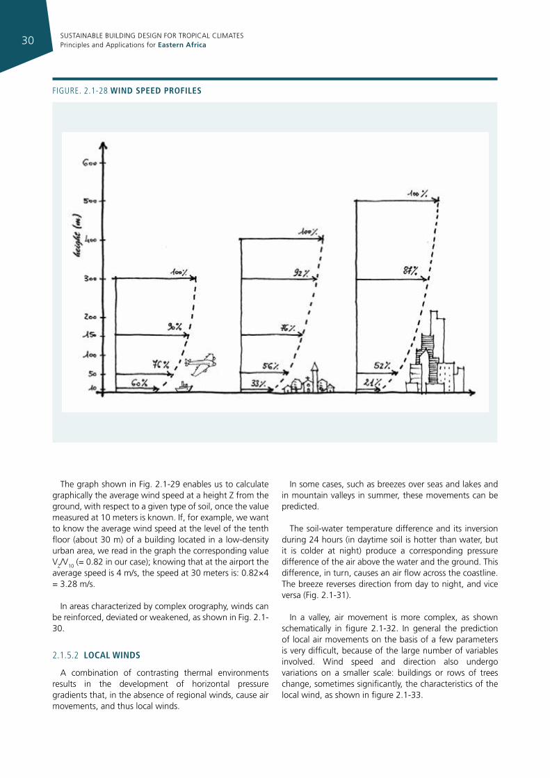
The effect of topography on regional winds is remarkable and can be quantitatively assessed. On flat ground, without obstructions, wind speed varies as a function of two parameters: surface roughness of the ground and height. In figure 2.1-28 some examples of wind speed profiles are shown; it may be noted that - at the same height - velocity is greater in open countryside than in an area of high building density. Wind is measured by weather stations, situated in a given topographical context. Changing this context also changes the speed, which also changes, in the same site, in relation to the height.
Usually, wind data available for a location are those measured at the nearest airport, at a height of 10 m from the ground.
To calculate wind speed at different heights, the following formula can be used:
(2.1-3)
where: VZ = wind speed at the height Z [m/s]; V10 = wind speed at 10 m [m/s];
K and α are two coefficients that vary depending on the type of ground, as shown in Table 2.1-5.
Figure. 2.1-27 WInd rose
terrain type α k
i - Open countryside, flatland 0.17 0.68
ii - Low-density urban periphery 0.20 0.52
iii – urban area 0.25 0.35
iV – Downtown 0.33 0.21
TABLe 2.1-5 correctIon factors as a functIon of the heIght and roughness of the ground
SUSTAINABLE BUILDING DESIGN FOR TROPICAL CLIMATES Principles and Applications for Eastern Africa30
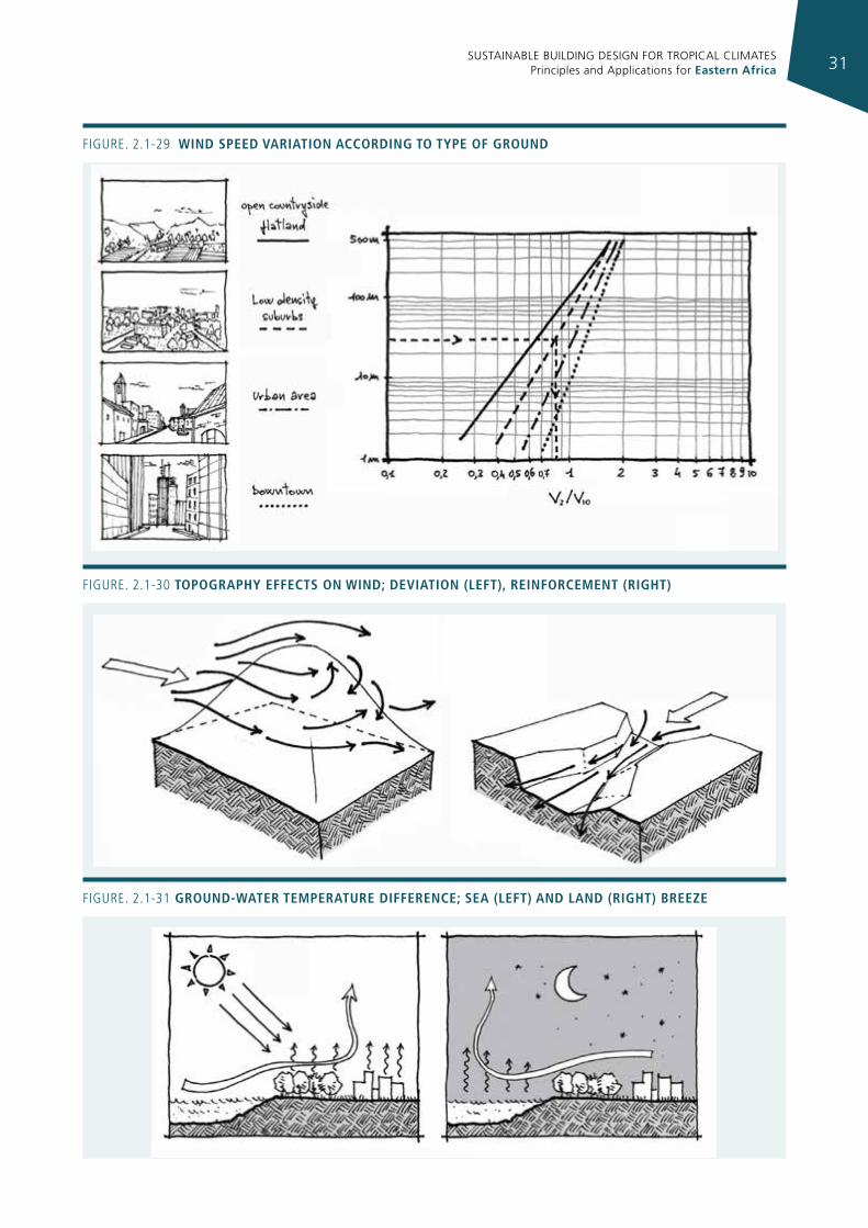
The graph shown in Fig. 2.1-29 enables us to calculate graphically the average wind speed at a height Z from the ground, with respect to a given type of soil, once the value measured at 10 meters is known. If, for example, we want to know the average wind speed at the level of the tenth floor (about 30 m) of a building located in a low-density urban area, we read in the graph the corresponding value VZ/V10 (= 0.82 in our case); knowing that at the airport the average speed is 4 m/s, the speed at 30 meters is: 0.82×4 = 3.28 m/s.
In areas characterized by complex orography, winds can be reinforced, deviated or weakened, as shown in Fig. 2.1-30.
2.1.5.2 local WInds
A combination of contrasting thermal environments results in the development of horizontal pressure gradients that, in the absence of regional winds, cause air movements, and thus local winds.
In some cases, such as breezes over seas and lakes and in mountain valleys in summer, these movements can be predicted.
The soil-water temperature difference and its inversion during 24 hours (in daytime soil is hotter than water, but it is colder at night) produce a corresponding pressure difference of the air above the water and the ground. This difference, in turn, causes an air flow across the coastline. The breeze reverses direction from day to night, and vice versa (Fig. 2.1-31).
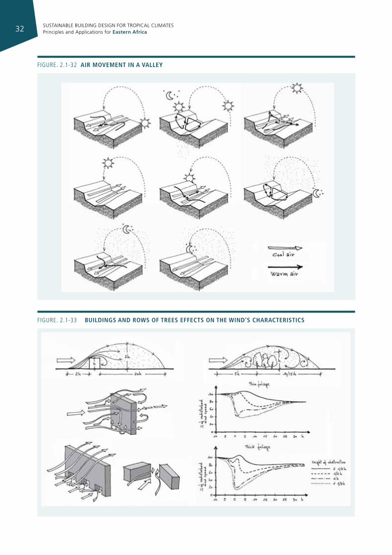
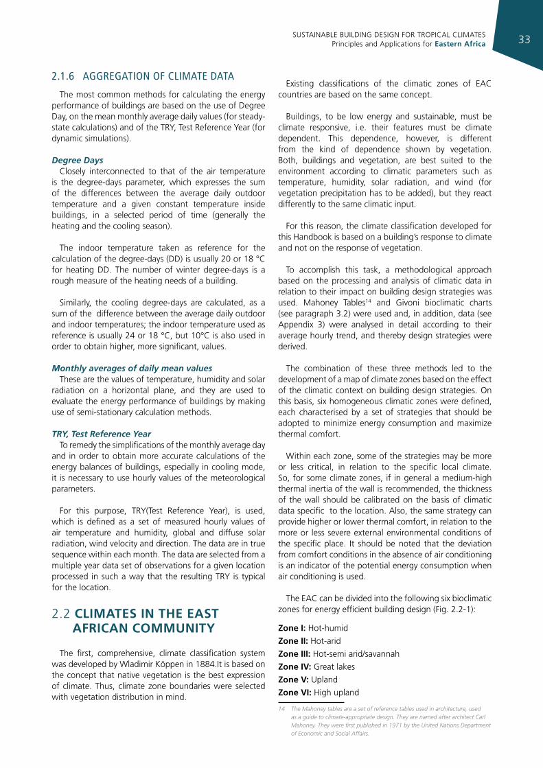
In a valley, air movement is more complex, as shown schematically in figure 2.1-32. In general the prediction of local air movements on the basis of a few parameters is very difficult, because of the large number of variables involved. Wind speed and direction also undergo variations on a smaller scale: buildings or rows of trees change, sometimes significantly, the characteristics of the local wind, as shown in figure 2.1-33.
Figure. 2.1-28 WInd speed profIles
SUSTAINABLE BUILDING DESIGN FOR TROPICAL CLIMATES Principles and Applications for Eastern Africa 31
Figure. 2.1-29 WInd speed varIatIon accordIng to type of ground
Figure. 2.1-30 topography effects on WInd; devIatIon (left), reInforcement (rIght)
Figure. 2.1-31 ground-Water temperature dIfference; sea (left) and land (rIght) breeze
SUSTAINABLE BUILDING DESIGN FOR TROPICAL CLIMATES Principles and Applications for Eastern Africa32
Figure. 2.1-32 aIr movement In a valley
Figure. 2.1-33 buIldIngs and roWs of trees effects on the WInd’s characterIstIcs
SUSTAINABLE BUILDING DESIGN FOR TROPICAL CLIMATES Principles and Applications for Eastern Africa 33
2.1.6 aggregaTIon of clImaTe daTa
The most common methods for calculating the energy performance of buildings are based on the use of Degree Day, on the mean monthly average daily values (for steady-state calculations) and of the TRY, Test Reference Year (for dynamic simulations).
Degree DaysClosely interconnected to that of the air temperature
is the degree-days parameter, which expresses the sum of the differences between the average daily outdoor temperature and a given constant temperature inside buildings, in a selected period of time (generally the heating and the cooling season).
The indoor temperature taken as reference for the calculation of the degree-days (DD) is usually 20 or 18 °C for heating DD. The number of winter degree-days is a rough measure of the heating needs of a building.
Similarly, the cooling degree-days are calculated, as a sum of the difference between the average daily outdoor and indoor temperatures; the indoor temperature used as reference is usually 24 or 18 °C, but 10°C is also used in order to obtain higher, more significant, values.
Monthly averages of daily mean valuesThese are the values of temperature, humidity and solar
radiation on a horizontal plane, and they are used to evaluate the energy performance of buildings by making use of semi-stationary calculation methods.
TRY, Test Reference YearTo remedy the simplifications of the monthly average day
and in order to obtain more accurate calculations of the energy balances of buildings, especially in cooling mode, it is necessary to use hourly values of the meteorological parameters.
For this purpose, TRY(Test Reference Year), is used, which is defined as a set of measured hourly values of air temperature and humidity, global and diffuse solar radiation, wind velocity and direction. The data are in true sequence within each month. The data are selected from a multiple year data set of observations for a given location processed in such a way that the resulting TRY is typical for the location.
2.2 CLIMAtES In tHE EASt AFRICAn CoMMunItY
The first, comprehensive, climate classification system was developed by Wladimir Köppen in 1884.It is based on the concept that native vegetation is the best expression of climate. Thus, climate zone boundaries were selected with vegetation distribution in mind.
Existing classifications of the climatic zones of EAC countries are based on the same concept.
Buildings, to be low energy and sustainable, must be climate responsive, i.e. their features must be climate dependent. This dependence, however, is different from the kind of dependence shown by vegetation. Both, buildings and vegetation, are best suited to the environment according to climatic parameters such as temperature, humidity, solar radiation, and wind (for vegetation precipitation has to be added), but they react differently to the same climatic input.
For this reason, the climate classification developed for this Handbook is based on a building’s response to climate and not on the response of vegetation.
To accomplish this task, a methodological approach based on the processing and analysis of climatic data in relation to their impact on building design strategies was used. Mahoney Tables14 and Givoni bioclimatic charts (see paragraph 3.2) were used and, in addition, data (see Appendix 3) were analysed in detail according to their average hourly trend, and thereby design strategies were derived.
The combination of these three methods led to the development of a map of climate zones based on the effect of the climatic context on building design strategies. On this basis, six homogeneous climatic zones were defined, each characterised by a set of strategies that should be adopted to minimize energy consumption and maximize thermal comfort.
Within each zone, some of the strategies may be more or less critical, in relation to the specific local climate. So, for some climate zones, if in general a medium-high thermal inertia of the wall is recommended, the thickness of the wall should be calibrated on the basis of climatic data specific to the location. Also, the same strategy can provide higher or lower thermal comfort, in relation to the more or less severe external environmental conditions of the specific place. It should be noted that the deviation from comfort conditions in the absence of air conditioning is an indicator of the potential energy consumption when air conditioning is used.
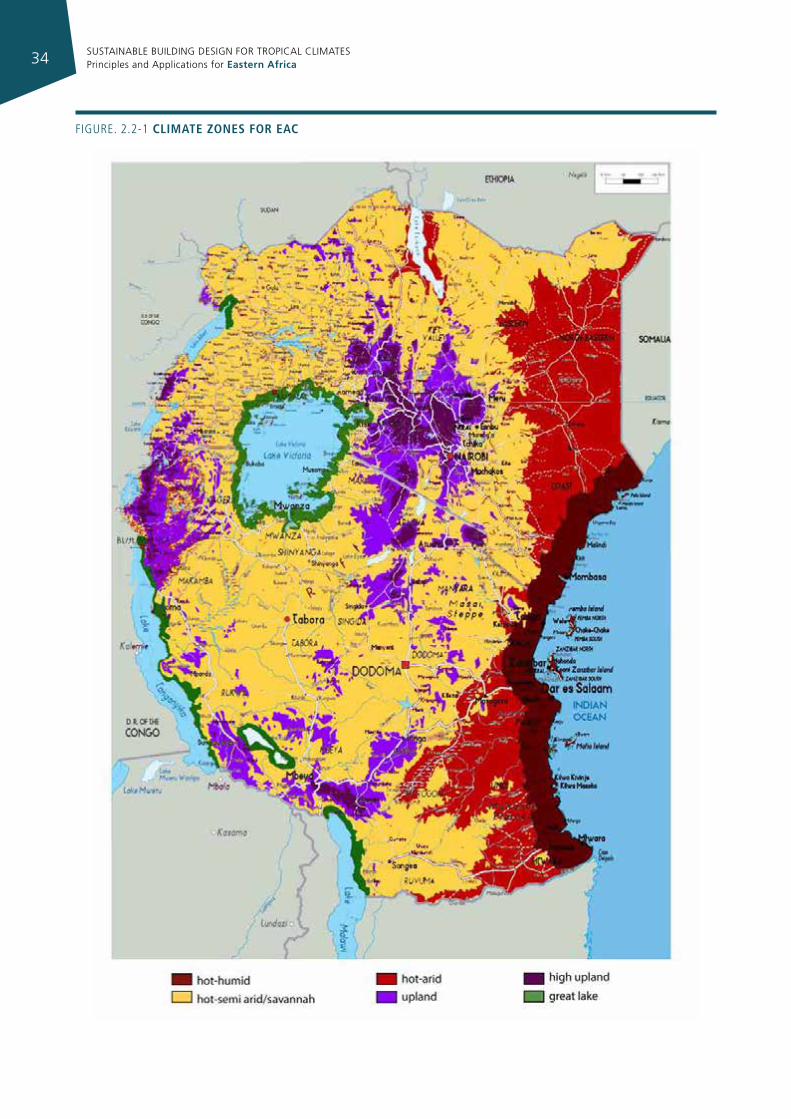
The EAC can be divided into the following six bioclimatic zones for energy efficient building design (Fig. 2.2-1):
Zone I: Hot-humid
Zone II: Hot-arid
Zone III: Hot-semi arid/savannah
Zone Iv: Great lakes
Zone v: Upland
Zone vI: High upland
14 The Mahoney tables are a set of reference tables used in architecture, used as a guide to climate-appropriate design. They are named after architect Carl Mahoney. They were first published in 1971 by the United Nations Department of Economic and Social Affairs.
SUSTAINABLE BUILDING DESIGN FOR TROPICAL CLIMATES Principles and Applications for Eastern Africa34
Figure. 2.2-1 clImate zones for eac
SUSTAINABLE BUILDING DESIGN FOR TROPICAL CLIMATES Principles and Applications for Eastern Africa 35
ZONe i: hot-humId
This zone includes the coastal areas, islands and a strip of land from 20 to 100 km wide along the coast. Most of the zone is less than 300 m above sea level. It is never excessively hot, but has high humidity, which causes discomfort. The zone is characterized by permanent high humidity, generally high temperatures, small daily temperature swing, moderate breezes and high values of solar radiation, except on cloudy days. Along the coast and up to 2-8 km inland, depending on the terrain the prevailing north-east and south-east monsoon winds are modified by sea-land breezes during the day and, to a much lesser extent, by land-sea breezes at night.
In the hottest month, the mean maximum air temperature is about 32 °C, the mean minimum air temperature is 25-26 °C, and the mean temperature swing is about 3-7 °C. The mean relative humidity along the coastal area is about 80%, and for the strip of land from 20-100 km along the coast, the mean relative humidity is 65%-72%. A more comfortable season is experienced between June and September due to a small temperature drop together with a lower humidity level and relatively higher wind velocity.
Global solar radiation over a horizontal surface is 5.0-5.4 kWh/m2 day and progressively lowers to 4.5 kWh/m2
moving away from the coastline. The cooling degree days (base 10°C) are in the range of 5500-6200. The monsoons blow from the northeast from November to March and from the southeast from April to September.
The average annual precipitation is 900-1250 mm.
Some of the representative locations for this zone are: Mombasa, Malindi (Kenya), Dar es Salaam and Tanga (Tanzania).
ComfortThe combination of high temperatures and high
humidity causes discomfort. Ventilation that facilitates convective and evaporative cooling of the body is essential for comfort by both day and night.
Nights, which are often still and sultry, bring little or no relief to the heat of the day. Even correctly designed lightweight houses will release heat, very often causing an indoor temperature higher than that of outdoors Therefore, minimizing discomfort at night is of utmost importance.
The period from June to September is less critical.
A high incidence of glare can be expected from bright overcast skies.
ZONe ii: hot-arId
The hot-arid zone includes the areas that are far from the sea, with altitudes ranging from 0 m to 500 m.
Maximum temperatures are high, higher than those of the hot-humid climate and the daily temperature variation is also high. Humidity, especially in the hottest hours, is low. Breezes are generally light with no strong predominant direction.
The wet and dry seasons correspond to the wet and dry seasons on the coast at the same latitude, and both these seasons are much drier.
For the hottest month, the mean maximum air temperature is about 36 °C, the mean minimum air temperature is 23 °C, the mean temperature swing is about 12 °C, mean relative humidity is about 40%, and global solar radiation over a horizontal surface is about 7.0 kWh/m2 day. The cooling degree days are about 6700-7200. The average annual Rainfall is 0-500 mm.
Some of the representative locations for this zone are: Garissa and Lodwar (Kenya).
Comfort Days are invariably very hot. The high daytime
temperatures are accompanied by moderate to low humidity such that even a gentle breeze will usually be sufficient to prevent skin surfaces from becoming moist. Low humidity in the hottest hours attenuates the level of discomfort and a wider daily temperature swing means that nights are relatively comfortable. Winds are generally weak, and persistent, at times strong winds are experienced locally. Sudden severe and violent windstorms accompanied by thick rising sand occur from time to time in some parts of the zone (e.g. Lake Turkana). Fresh breezes from mid to late evening are common in some places (e.g. Garissa).
Heat during the day imposes severe restrictions on people’s outdoor activities. Houses should aim at keeping indoor temperatures low during hot days, and should be provided with shaded outdoor areas where occupants can carry out various activities. Very often people like to rest and sleep inside during these hot hours.
ZONe iii: hot-semI arId / savannah
This zone covers the widest area of the EAC, and includes some parts of Kenya and a large part of Tanzania and Uganda, with altitudes ranging from 500 m to 1500 m. The difference between this zone and the hot-arid zone is that it has relatively higher humidity values, lower peak temperatures and smaller daily temperature swings.
SUSTAINABLE BUILDING DESIGN FOR TROPICAL CLIMATES Principles and Applications for Eastern Africa36
The mean air temperature range is 20-22 °C. In summer the temperatures are about 29-31 °C and can rise to 33 °C in semi arid areas. Mean relative humidity is about 65%, but it can go as low as 40% in parts of the savannah plains. Global solar radiation over a horizontal surface is about 6.3 kWh/m2 day. The cooling degree days are 4600-5400.
The mean annual rainfall varies according to topography and ranges from 500 mm-750 mm in semi arid areas to 1000-1500 mm in savannah regions.
Some of the representative locations for this zone are: Machakos, Isiolo, Mavoko, Thika (Kenya), Tabora, Dodoma (Tanzania), Gulu, Kabale, Iganga, Kasese, Lira (Uganda).
ComfortThe comfort conditions are similar to those in the the
hot-arid climate zone.
The discomfort caused by the high daytime temperatures that prevail during most of the year can be critical, though steady breezes often alleviate the heat of the afternoon. It can be chilly during the cloudy months of July and August and during and immediately after rains.
Mosquitoes are troublesome in some of the small townships, particularly where stagnant water abounds.
Comfort conditions at night vary considerably over the year. It is often likely to be uncomfortably warm inside massive walls and poorly ventilated houses. From June to August and during the rainy season it can, however, be distinctly cool at night.
ZONe iV: great lakes
This zone includes a strip 0-25 km wide along the shores of Lakes Victoria, Nyasa, Rukwa and Tanganyika. The zone ranges in average from lake level to about 150 m above lake level.
The temperature is slightly lower than that in the savannah zones, but daily variations are comparable.
Due to the lakes, humidity is higher than in the savannah zone, even though it is in the same altitude range.
In the hottest month, the mean maximum air temperature is about 28-29 °C, the mean minimum air temperature is 16-17 °C, the mean temperature swing is about 12 °C, the mean relative humidity is about 60-70%, and global solar radiation over a horizontal surface is about 5.5 kWh/m2 day. The average annual precipitation is more than 1200 mm.
The cooling degree days are about 4100-4800.
Some of the representative locations for this zone are: Kisumu, Homabay, Kakamega (Kenya), Bukoba, Mwanza (Tanzania), Kampala, Hoima, Jinja (Uganda), Kibuye, Gisenye (Rwanda), Bujumbura (Burundi).
Comfort This is a remarkably stable climate. There are very slight
seasonal and daily differences in temperature and humidity. Day temperatures are rather similar to those in the the hot-humid Coastal Zone, but nights may be uncomfortably cold for some periods of the year. The hot and comparatively humid climate of this zone is considerably modified by the zone’s altitude, from 475 m (Lake Nyasa) to 1133 m (Lake Victoria). Due to the high altitude of Lake Victoria, early mornings may be uncomfortably cold during the cold season and the rains. Therefore, complete sun exclusion is not desirable in this area, whereas in other parts of the zone sun exclusion is required. Shaded outdoor spaces facing the lake in order to catch the cooling afternoon breeze are highly appreciated.
During chilly and rainy mornings, the heat from a fire is most desirable.
ZONe V: upland
This zone refers to areas at altitudes between about 1500 and 2000 m, mainly mountains and plateaus. They are generally cool areas where some heating is welcome on the coolest days of the year. High relative humidity is rare during the day, but is the norm at night. Breezes are moderate with no predominant direction.
For the hottest month, the mean maximum air temperature is about 26-27 °C, the mean minimum air temperature is 14-16 °C, the mean temperature swing is about 10-12 °C, mean relative humidity is about 60-65%, and global solar radiation on horizontal surface about 6-7 kWh/m2 day.
For the coldest month, the mean maximum air temperature is about 20-24 °C, the mean minimum air temperature is 14-15 °C, the mean temperature swing is about 6-10 °C, mean relative humidity is about 60-75%, and global solar radiation over a horizontal surface is about 5-6 kWh/m2 day. The heating degree-days are about 25-370 (base 18 °C) and the cooling degree days are about 3000-3700.
The average annual precipitation is more than1200 mm.
Some of the representative locations for this zone are: Nairobi, Kitale, Nakuru (Kenya), Arusha, Mbeya, Iringa (Tanzania), Mbale (Uganda), Kigali (Rwanda).
SUSTAINABLE BUILDING DESIGN FOR TROPICAL CLIMATES Principles and Applications for Eastern Africa 37
ComfortThe upland zone has a pleasant climate. Because of the
high altitude, the conditions in this zone are similar to spring or autumn in a temperate climate. Temperatures are moderate and during daytime rarely exceed the upper limits of the comfort zones. During nighttime, the temperature is likely to drop below the lower limit of the comfort zone.
The low night temperatures are a major source of discomfort.
ZONe Vi: hIgh upland
This zone refers to altitudes above 2000m. These are generally cold areas where heating is necessary for most of the year. The humidity is fairly high. For the coldest month, the mean maximum air temperature is about 20 °C, the mean minimum air temperature is 12 °C, the mean temperature swing is about 8 °C, mean relative humidity is about 80%, and global solar radiation over a horizontal surface is about 5.3 kWh/m2 day. The heating degree-days are more than 480. The cooling degree-days are less than 3700. The average annual precipitation is more than 1200 mm.
One of the representative locations for this zone is Eldoret (Kenya).
ComfortDue to the altitude, daytime temperatures are never high,
but nights are very cold. During most nights, temperatures are well below the comfort zone, and a rapid temperature drop takes place at sunset.
The zone contains a large number of exposed localities with brisk winds and good air movement, which in cold weather may be uncomfortable. However, high wind velocities are uncommon.
The frequent cold and rainy weather makes people stay indoors close to the fire.
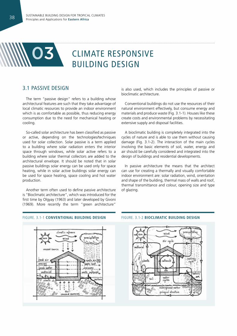
SUSTAINABLE BUILDING DESIGN FOR TROPICAL CLIMATES Principles and Applications for Eastern Africa38
clImaTe responsIve buIldIng desIgn
03
3.1 passIve desIgn
The term “passive design” refers to a building whose architectural features are such that they take advantage of local climatic resources to provide an indoor environment which is as comfortable as possible, thus reducing energy consumption due to the need for mechanical heating or cooling.
So-called solar architecture has been classified as passive or active, depending on the technologies/techniques used for solar collection. Solar passive is a term applied to a building where solar radiation enters the interior space through windows, while solar active refers to a building where solar thermal collectors are added to the architectural envelope. It should be noted that in solar passive buildings solar energy can be used only for space heating, while in solar active buildings solar energy can be used for space heating, space cooling and hot water production.
Another term often used to define passive architecture is “Bioclimatic architecture”, which was introduced for the first time by Olgyay (1963) and later developed by Givoni (1969). More recently the term “green architecture”
is also used, which includes the principles of passive or bioclimatic architecture.
Conventional buildings do not use the resources of their natural environment effectively, but consume energy and materials and produce waste (Fig. 3.1-1). Houses like these create costs and environmental problems by necessitating extensive supply and disposal facilities.
A bioclimatic building is completely integrated into the cycles of nature and is able to use them without causing damage (Fig. 3.1-2). The interaction of the main cycles involving the basic elements of soil, water, energy and air should be carefully considered and integrated into the design of buildings and residential developments.
In passive architecture the means that the architect can use for creating a thermally and visually comfortable indoor environment are: solar radiation, wind, orientation and shape of the building, thermal mass of walls and roof, thermal transmittance and colour, opening size and type of glazing.
Figure. 3.1-1 conventIonal buIldIng desIgn Figure. 3.1-2 bIoclImatIc buIldIng desIgn
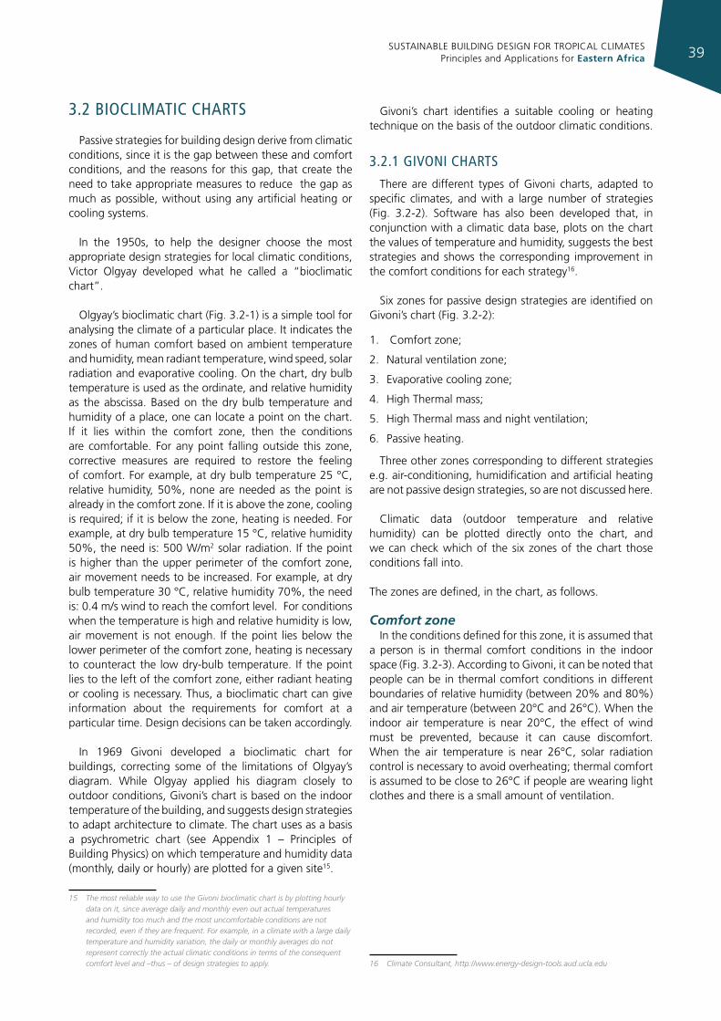
SUSTAINABLE BUILDING DESIGN FOR TROPICAL CLIMATES Principles and Applications for Eastern Africa 39
3.2 bIoclImaTIc charTs
Passive strategies for building design derive from climatic conditions, since it is the gap between these and comfort conditions, and the reasons for this gap, that create the need to take appropriate measures to reduce the gap as much as possible, without using any artificial heating or cooling systems.
In the 1950s, to help the designer choose the most appropriate design strategies for local climatic conditions, Victor Olgyay developed what he called a “bioclimatic chart”.
Olgyay’s bioclimatic chart (Fig. 3.2-1) is a simple tool for analysing the climate of a particular place. It indicates the zones of human comfort based on ambient temperature and humidity, mean radiant temperature, wind speed, solar radiation and evaporative cooling. On the chart, dry bulb temperature is used as the ordinate, and relative humidity as the abscissa. Based on the dry bulb temperature and humidity of a place, one can locate a point on the chart. If it lies within the comfort zone, then the conditions are comfortable. For any point falling outside this zone, corrective measures are required to restore the feeling of comfort. For example, at dry bulb temperature 25 °C, relative humidity, 50%, none are needed as the point is already in the comfort zone. If it is above the zone, cooling is required; if it is below the zone, heating is needed. For example, at dry bulb temperature 15 °C, relative humidity 50%, the need is: 500 W/m2 solar radiation. If the point is higher than the upper perimeter of the comfort zone, air movement needs to be increased. For example, at dry bulb temperature 30 °C, relative humidity 70%, the need is: 0.4 m/s wind to reach the comfort level. For conditions when the temperature is high and relative humidity is low, air movement is not enough. If the point lies below the lower perimeter of the comfort zone, heating is necessary to counteract the low dry-bulb temperature. If the point lies to the left of the comfort zone, either radiant heating or cooling is necessary. Thus, a bioclimatic chart can give information about the requirements for comfort at a particular time. Design decisions can be taken accordingly.
In 1969 Givoni developed a bioclimatic chart for buildings, correcting some of the limitations of Olgyay’s diagram. While Olgyay applied his diagram closely to outdoor conditions, Givoni’s chart is based on the indoor temperature of the building, and suggests design strategies to adapt architecture to climate. The chart uses as a basis a psychrometric chart (see Appendix 1 – Principles of Building Physics) on which temperature and humidity data (monthly, daily or hourly) are plotted for a given site15.
15 The most reliable way to use the Givoni bioclimatic chart is by plotting hourly data on it, since average daily and monthly even out actual temperatures and humidity too much and the most uncomfortable conditions are not recorded, even if they are frequent. For example, in a climate with a large daily temperature and humidity variation, the daily or monthly averages do not represent correctly the actual climatic conditions in terms of the consequent comfort level and –thus – of design strategies to apply.
Givoni’s chart identifies a suitable cooling or heating technique on the basis of the outdoor climatic conditions.
3.2.1 gIvonI charTs
There are different types of Givoni charts, adapted to specific climates, and with a large number of strategies (Fig. 3.2-2). Software has also been developed that, in conjunction with a climatic data base, plots on the chart the values of temperature and humidity, suggests the best strategies and shows the corresponding improvement in the comfort conditions for each strategy16.
Six zones for passive design strategies are identified on Givoni’s chart (Fig. 3.2-2):
1. Comfort zone;
2. Natural ventilation zone;
3. Evaporative cooling zone;
4. High Thermal mass;
5. High Thermal mass and night ventilation;
6. Passive heating.
Three other zones corresponding to different strategies e.g. air-conditioning, humidification and artificial heating are not passive design strategies, so are not discussed here.
Climatic data (outdoor temperature and relative humidity) can be plotted directly onto the chart, and we can check which of the six zones of the chart those conditions fall into.
The zones are defined, in the chart, as follows.
Comfort zoneIn the conditions defined for this zone, it is assumed that
a person is in thermal comfort conditions in the indoor space (Fig. 3.2-3). According to Givoni, it can be noted that people can be in thermal comfort conditions in different boundaries of relative humidity (between 20% and 80%) and air temperature (between 20°C and 26°C). When the indoor air temperature is near 20°C, the effect of wind must be prevented, because it can cause discomfort. When the air temperature is near 26°C, solar radiation control is necessary to avoid overheating; thermal comfort is assumed to be close to 26°C if people are wearing light clothes and there is a small amount of ventilation.
16 Climate Consultant, http://www.energy-design-tools.aud.ucla.edu
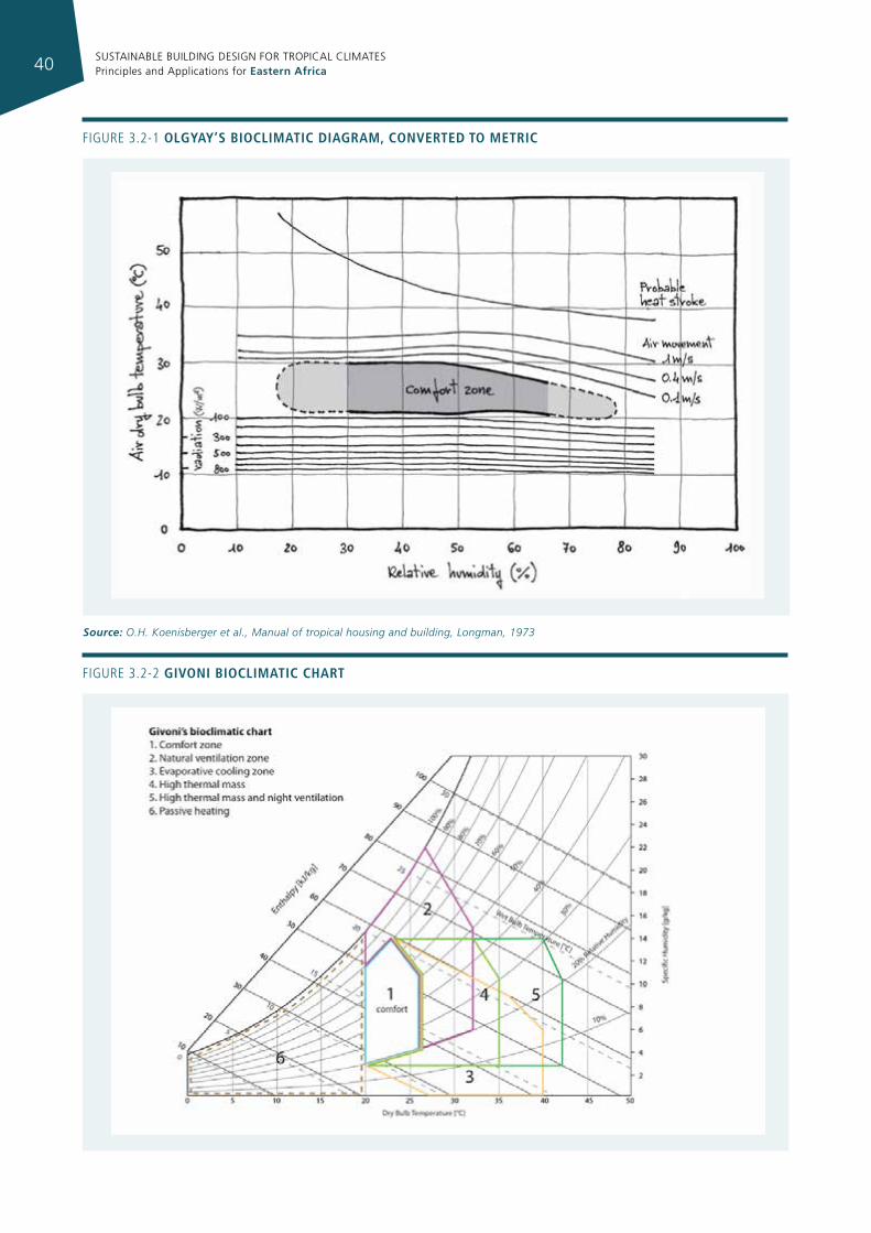
SUSTAINABLE BUILDING DESIGN FOR TROPICAL CLIMATES Principles and Applications for Eastern Africa40
Figure 3.2-1 olgyay’s bIoclImatIc dIagram, converted to metrIc
Source: O.H. Koenisberger et al., Manual of tropical housing and building, Longman, 1973
Figure 3.2-2 gIvonI bIoclImatIc chart
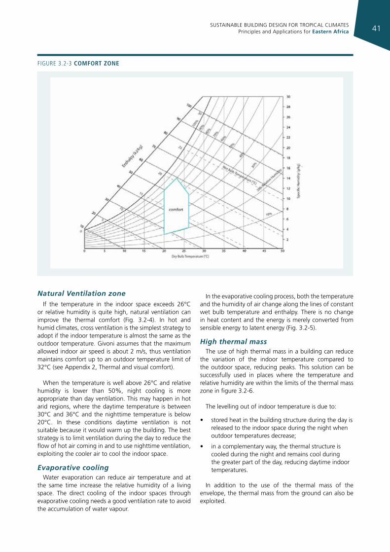
SUSTAINABLE BUILDING DESIGN FOR TROPICAL CLIMATES Principles and Applications for Eastern Africa 41
Figure 3.2-3 comfort zone
Natural Ventilation zoneIf the temperature in the indoor space exceeds 26°C
or relative humidity is quite high, natural ventilation can improve the thermal comfort (Fig. 3.2-4). In hot and humid climates, cross ventilation is the simplest strategy to adopt if the indoor temperature is almost the same as the outdoor temperature. Givoni assumes that the maximum allowed indoor air speed is about 2 m/s, thus ventilation maintains comfort up to an outdoor temperature limit of 32°C (see Appendix 2, Thermal and visual comfort).
When the temperature is well above 26°C and relative humidity is lower than 50%, night cooling is more appropriate than day ventilation. This may happen in hot arid regions, where the daytime temperature is between 30°C and 36°C and the nighttime temperature is below 20°C. In these conditions daytime ventilation is not suitable because it would warm up the building. The best strategy is to limit ventilation during the day to reduce the flow of hot air coming in and to use nighttime ventilation, exploiting the cooler air to cool the indoor space.
Evaporative coolingWater evaporation can reduce air temperature and at
the same time increase the relative humidity of a living space. The direct cooling of the indoor spaces through evaporative cooling needs a good ventilation rate to avoid the accumulation of water vapour.
In the evaporative cooling process, both the temperature and the humidity of air change along the lines of constant wet bulb temperature and enthalpy. There is no change in heat content and the energy is merely converted from sensible energy to latent energy (Fig. 3.2-5).
High thermal mass The use of high thermal mass in a building can reduce
the variation of the indoor temperature compared to the outdoor space, reducing peaks. This solution can be successfully used in places where the temperature and relative humidity are within the limits of the thermal mass zone in figure 3.2-6.
The levelling out of indoor temperature is due to:
• stored heat in the building structure during the day is released to the indoor space during the night when outdoor temperatures decrease;
• in a complementary way, the thermal structure is cooled during the night and remains cool during the greater part of the day, reducing daytime indoor temperatures.
In addition to the use of the thermal mass of the envelope, the thermal mass from the ground can also be exploited.
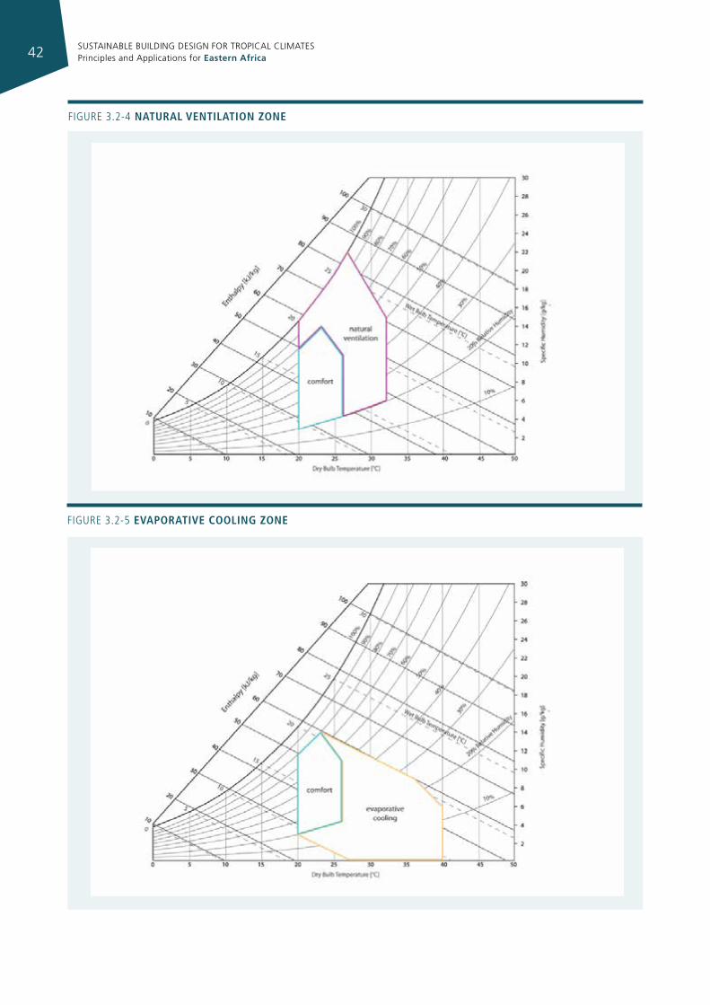
SUSTAINABLE BUILDING DESIGN FOR TROPICAL CLIMATES Principles and Applications for Eastern Africa42
Figure 3.2-4 natural ventIlatIon zone
Figure 3.2-5 evaporatIve coolIng zone
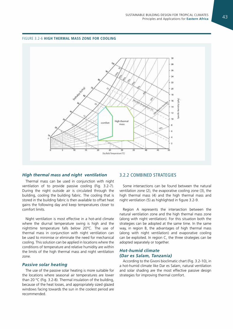
SUSTAINABLE BUILDING DESIGN FOR TROPICAL CLIMATES Principles and Applications for Eastern Africa 43
High thermal mass and night ventilationThermal mass can be used in conjunction with night
ventilation of to provide passive cooling (Fig. 3.2-7). During the night outside air is circulated through the building, cooling the building fabric. The cooling that is stored in the building fabric is then available to offset heat gains the following day and keep temperatures closer to comfort limits.
Night ventilation is most effective in a hot-arid climate where the diurnal temperature swing is high and the nighttime temperature falls below 20°C. The use of thermal mass in conjunction with night ventilation can be used to minimise or eliminate the need for mechanical cooling. This solution can be applied in locations where the conditions of temperature and relative humidity are within the limits of the high thermal mass and night ventilation zone.
Passive solar heatingThe use of the passive solar heating is more suitable for
the locations where seasonal air temperatures are lower than 20 °C (Fig. 3.2-8). Thermal insulation of the building, because of the heat losses, and appropriately sized glazed windows facing towards the sun in the coolest period are recommended.
3.2.2 combIned sTraTegIes
Some intersections can be found between the natural ventilation zone (2), the evaporative cooling zone (3), the high thermal mass (4) and the high thermal mass and night ventilation (5) as highlighted in figure 3.2-9.
Region A represents the intersection between the natural ventilation zone and the high thermal mass zone (along with night ventilation). For this situation both the strategies can be adopted at the same time. In the same way, in region B, the advantages of high thermal mass (along with night ventilation) and evaporative cooling can be exploited. In region C, the three strategies can be adopted separately or together.
Hot-humid climate (Dar es Salam, Tanzania)
According to the Givoni bioclimatic chart (Fig. 3.2-10), in a hot-humid climate like Dar es Salam, natural ventilation and solar shading are the most effective passive design strategies for improving thermal comfort.
Figure 3.2-6 hIgh thermal mass zone for coolIng
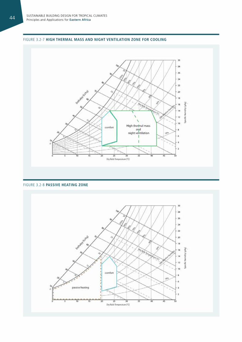
SUSTAINABLE BUILDING DESIGN FOR TROPICAL CLIMATES Principles and Applications for Eastern Africa44
Figure 3.2-7 hIgh thermal mass and nIght ventIlatIon zone for coolIng
Figure 3.2-8 passIve heatIng zone
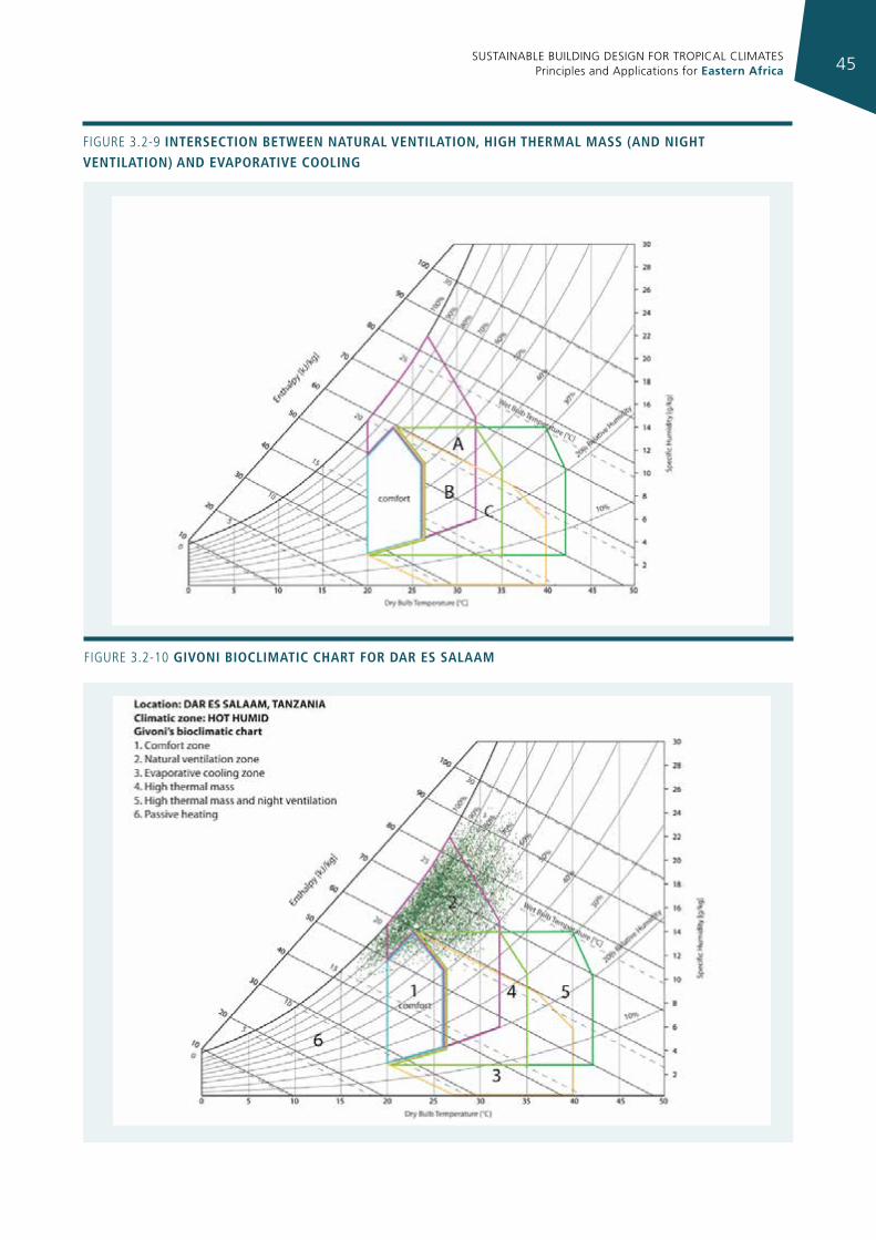
SUSTAINABLE BUILDING DESIGN FOR TROPICAL CLIMATES Principles and Applications for Eastern Africa 45
Figure 3.2-9 IntersectIon betWeen natural ventIlatIon, hIgh thermal mass (and nIght ventIlatIon) and evaporatIve coolIng
Figure 3.2-10 gIvonI bIoclImatIc chart for dar es salaam
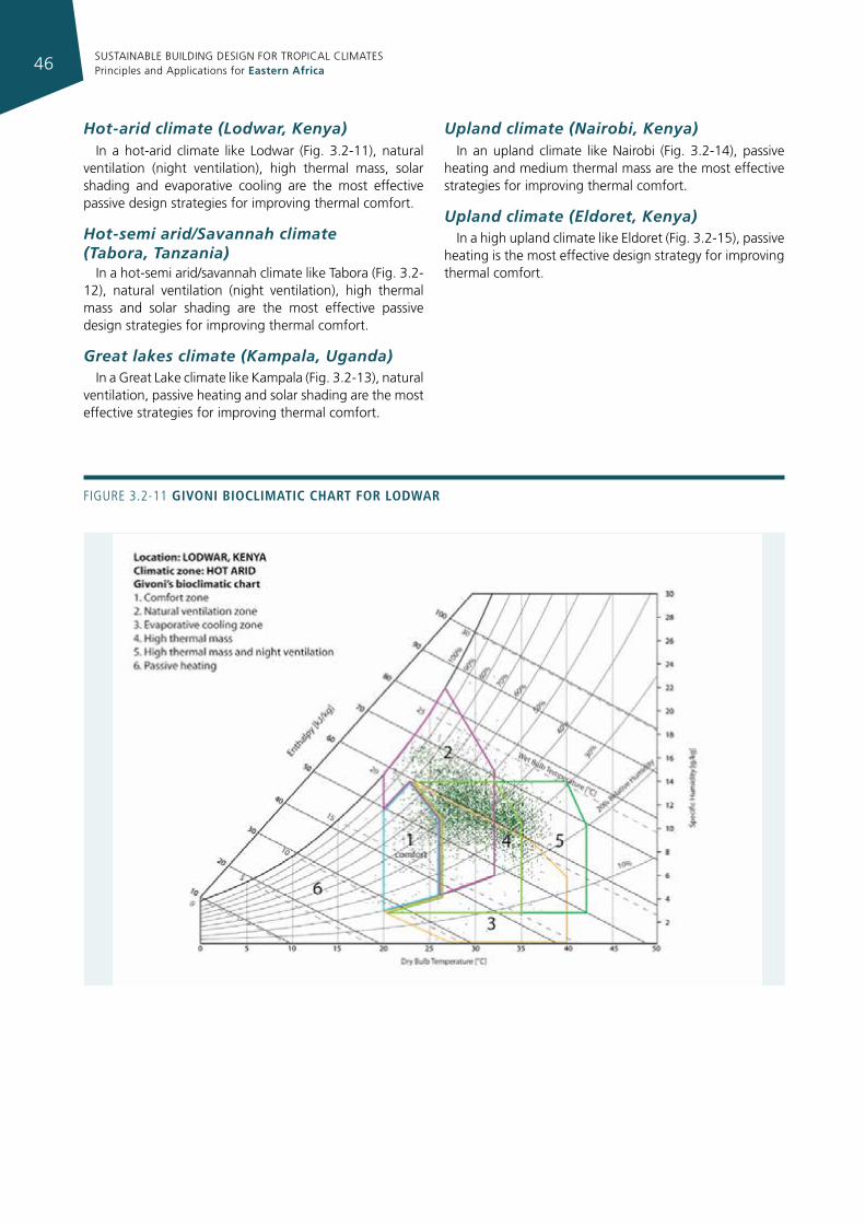
SUSTAINABLE BUILDING DESIGN FOR TROPICAL CLIMATES Principles and Applications for Eastern Africa46
Figure 3.2-11 gIvonI bIoclImatIc chart for lodWar
Hot-arid climate (Lodwar, Kenya)In a hot-arid climate like Lodwar (Fig. 3.2-11), natural
ventilation (night ventilation), high thermal mass, solar shading and evaporative cooling are the most effective passive design strategies for improving thermal comfort.
Hot-semi arid/Savannah climate (Tabora, Tanzania)
In a hot-semi arid/savannah climate like Tabora (Fig. 3.2-12), natural ventilation (night ventilation), high thermal mass and solar shading are the most effective passive design strategies for improving thermal comfort.
Great lakes climate (Kampala, Uganda)In a Great Lake climate like Kampala (Fig. 3.2-13), natural
ventilation, passive heating and solar shading are the most effective strategies for improving thermal comfort.
Upland climate (Nairobi, Kenya)In an upland climate like Nairobi (Fig. 3.2-14), passive
heating and medium thermal mass are the most effective strategies for improving thermal comfort.
Upland climate (Eldoret, Kenya)In a high upland climate like Eldoret (Fig. 3.2-15), passive
heating is the most effective design strategy for improving thermal comfort.
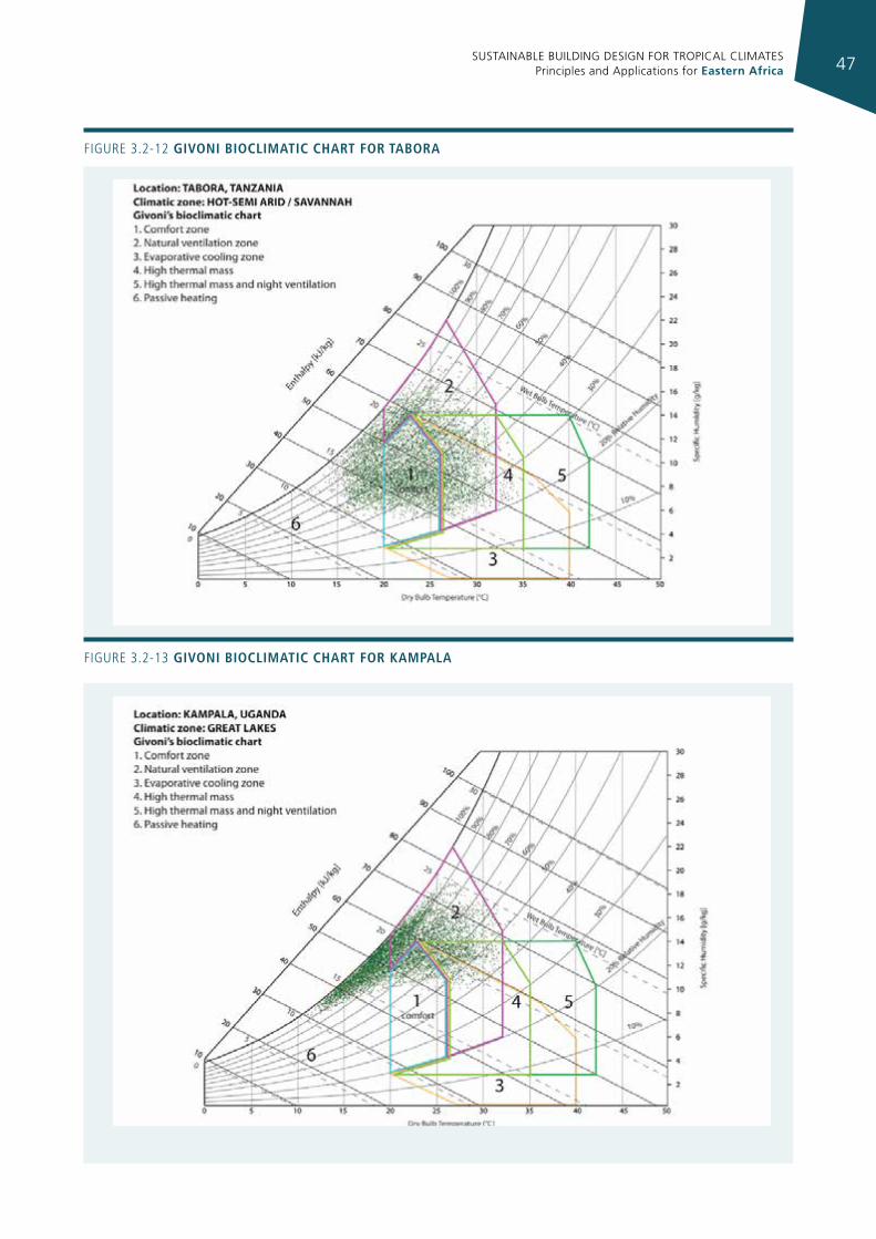
SUSTAINABLE BUILDING DESIGN FOR TROPICAL CLIMATES Principles and Applications for Eastern Africa 47
Figure 3.2-12 gIvonI bIoclImatIc chart for tabora
Figure 3.2-13 gIvonI bIoclImatIc chart for kampala
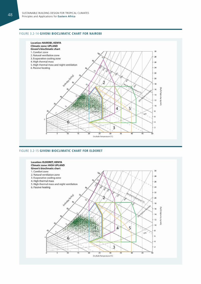
SUSTAINABLE BUILDING DESIGN FOR TROPICAL CLIMATES Principles and Applications for Eastern Africa48
Figure 3.2-14 gIvonI bIoclImatIc chart for naIrobI
Figure 3.2-15 gIvonI bIoclImatIc chart for eldoret
SUSTAINABLE BUILDING DESIGN FOR TROPICAL CLIMATES Principles and Applications for Eastern Africa 49
3.3 sITe plannIng
When urban planners start to design a new settlement, they usually look for pre-existing landmarks, such as roads, railways, rivers etc., and align the new buildings and streets accordingly. Very rarely do they look for the most ancient pre-existing landmarks: solar path and prevailing winds. However, analysis of these is very important in order to optimise the energy efficiency of the urban layout.
Low energy urban design means that shading and illumination of surfaces as well as wind must be analysed so that shape, orientation and distances between buildings can be optimised in order to control solar radiation and ventilation, with the aim of reducing the energy demands of individual buildings.
Sustainable site planning begins with an assessment of the building site in terms of its capability to provide natural resources, such as light, air, and water, and the extent to which the existing natural systems will be required to support the new development.
The process encompasses many steps, such as site selection, inventory, analysis, and development procedures.
The process is based on the concept of an interdependent natural system that links a series of interconnected geological, hydrological, topographical, ecological, climatological, and cultural attributes.
3.3.1 meThodology
The first step of energy conscious urban design is based on data collection and analysis as follows.
Data to be collected are:
• data about the macro and micro climate: detailed information about solar path, sky conditions and radiation, temperature range (seasonal minimum and maximum temperatures during night and day), humidity, precipitation, air movement etc.;
• data about the building site: topography, ventilation, orientation, vegetation, neighbouring structures, soil, water and air quality.
The analysis involves the adoption of solar diagrams, shading diagrams, comfort diagrams and tables.
Other information required is:
• data about building usage and cultural background: type of usage, period of usage, clothing, traditions and aesthetic values of occupants, traditional techniques and building materials;
• data about economic aspects: financial resources, available labour, materials and technologies.
3.3.1.1 mIcroclImate
The conditions which allow energy to flow through the building fabric and determine the thermal response of people are local and site-specific. These conditions are generally grouped under the term microclimate, which includes the wind, radiation, temperature, and humidity experienced around a building. A building by its very presence will change the microclimate by causing an obstruction to the wind flow, and by casting shadows on the ground and on other buildings. A designer has to predict this variation and take its effect into account in the design.
The microclimate of a site is affected by the following factors: landform, vegetation, water bodies, street width and orientation, open spaces and built form.
An understanding of these factors greatly helps in the preparation of the site layout plan.
The density and size of the built area affect the degree to which the microclimate can be modified in terms of wind conditions, air temperature, radiation balance, and natural lighting. This density depends on the proportion of the land covered by the buildings and the average height of the buildings (the effect of which can be modified by the relative heights of individual buildings on site).
Density also creates the heat island effect, which can be mitigated by reducing the total paved area allowed on site, and the services networks in terms of cost and technologies.
Each building type and combinations of different building types (i.e. detached/semi-detached, courtyard/patio, high rise and row buildings) form a matrix of environmental conditions that affect both macro and microclimate around and inside the building.
A correct mix of building types could help in achieving adequate sun protection and ventilation: high-rise buildings can increase ventilation in a dense development; low-rise buildings should be sited so that they avoid excessive heat exchange with the environment and utilize their link with open spaces.
3.3.1.2 urban layout and external space
Urban layout greatly depends on climate and should be designed differently in each climatic zone. The basic concerns are the provision of shading and air movement. The orientation of streets and the layout have a significant effect on the microclimate around buildings and on the access to sun and wind.
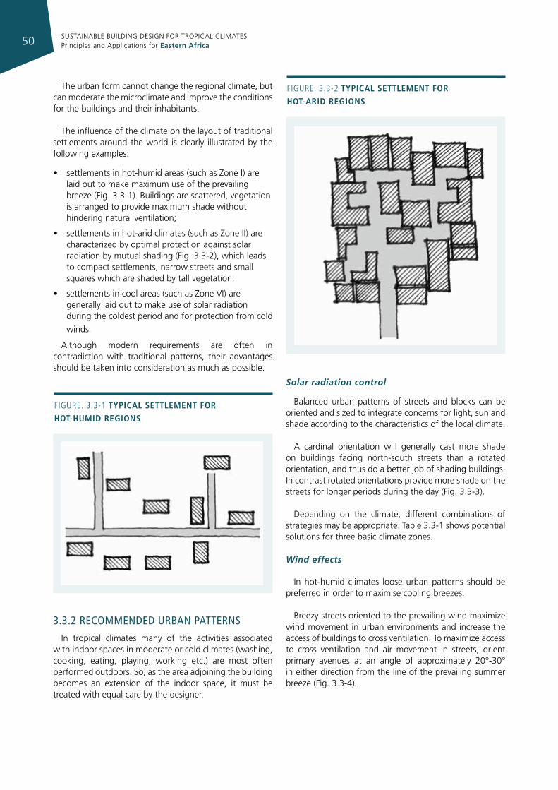
SUSTAINABLE BUILDING DESIGN FOR TROPICAL CLIMATES Principles and Applications for Eastern Africa50
The urban form cannot change the regional climate, but can moderate the microclimate and improve the conditions for the buildings and their inhabitants.
The influence of the climate on the layout of traditional settlements around the world is clearly illustrated by the following examples:
• settlements in hot-humid areas (such as Zone I) are laid out to make maximum use of the prevailing breeze (Fig. 3.3-1). Buildings are scattered, vegetation is arranged to provide maximum shade without hindering natural ventilation;
• settlements in hot-arid climates (such as Zone II) are characterized by optimal protection against solar radiation by mutual shading (Fig. 3.3-2), which leads to compact settlements, narrow streets and small squares which are shaded by tall vegetation;
• settlements in cool areas (such as Zone VI) are generally laid out to make use of solar radiation during the coldest period and for protection from cold
winds.
Although modern requirements are often in contradiction with traditional patterns, their advantages should be taken into consideration as much as possible.
3.3.2 recommended urban paTTerns
In tropical climates many of the activities associated with indoor spaces in moderate or cold climates (washing, cooking, eating, playing, working etc.) are most often performed outdoors. So, as the area adjoining the building becomes an extension of the indoor space, it must be treated with equal care by the designer.
Solar radiation control Balanced urban patterns of streets and blocks can be
oriented and sized to integrate concerns for light, sun and shade according to the characteristics of the local climate.
A cardinal orientation will generally cast more shade on buildings facing north-south streets than a rotated orientation, and thus do a better job of shading buildings. In contrast rotated orientations provide more shade on the streets for longer periods during the day (Fig. 3.3-3).
Depending on the climate, different combinations of strategies may be appropriate. Table 3.3-1 shows potential solutions for three basic climate zones.
Wind effects
In hot-humid climates loose urban patterns should be preferred in order to maximise cooling breezes.
Breezy streets oriented to the prevailing wind maximize wind movement in urban environments and increase the access of buildings to cross ventilation. To maximize access to cross ventilation and air movement in streets, orient primary avenues at an angle of approximately 20°-30° in either direction from the line of the prevailing summer breeze (Fig. 3.3-4).
Figure. 3.3-1 typIcal settlement for hot-humId regIons
Figure. 3.3-2 typIcal settlement for hot-arId regIons
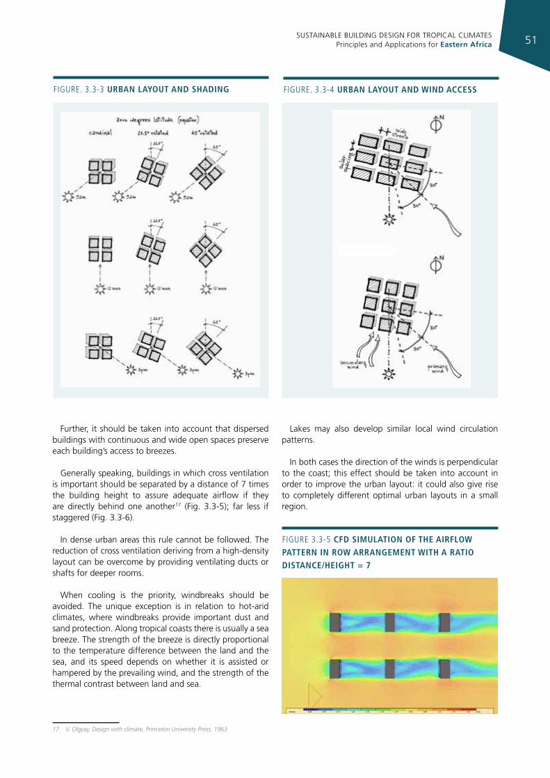
SUSTAINABLE BUILDING DESIGN FOR TROPICAL CLIMATES Principles and Applications for Eastern Africa 51
Figure. 3.3-3 urban layout and shadIng
Further, it should be taken into account that dispersed buildings with continuous and wide open spaces preserve each building’s access to breezes.
Generally speaking, buildings in which cross ventilation is important should be separated by a distance of 7 times the building height to assure adequate airflow if they are directly behind one another17 (Fig. 3.3-5); far less if staggered (Fig. 3.3-6).
In dense urban areas this rule cannot be followed. The reduction of cross ventilation deriving from a high-density layout can be overcome by providing ventilating ducts or shafts for deeper rooms.
When cooling is the priority, windbreaks should be avoided. The unique exception is in relation to hot-arid climates, where windbreaks provide important dust and sand protection. Along tropical coasts there is usually a sea breeze. The strength of the breeze is directly proportional to the temperature difference between the land and the sea, and its speed depends on whether it is assisted or hampered by the prevailing wind, and the strength of the thermal contrast between land and sea.
17 V. Olgyay, Design with climate, Princeton University Press, 1963
Lakes may also develop similar local wind circulation patterns.
In both cases the direction of the winds is perpendicular to the coast; this effect should be taken into account in order to improve the urban layout: it could also give rise to completely different optimal urban layouts in a small region.
Figure. 3.3-4 urban layout and WInd access
Figure 3.3-5 cfd sImulatIon of the aIrfloW pattern In roW arrangement WIth a ratIo dIstance/heIght = 7
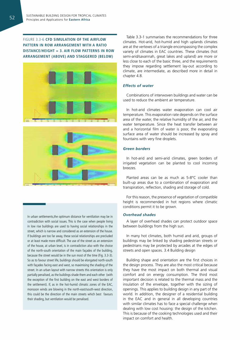
SUSTAINABLE BUILDING DESIGN FOR TROPICAL CLIMATES Principles and Applications for Eastern Africa52
Table 3.3-1 summarises the recommendations for three climates. Hot-arid, hot-humid and high uplands climates are at the vertexes of a triangle encompassing the complex variety of climates in EAC countries. These climates (hot semi-arid/savannah, great lakes and upland) are more or less close to each of the basic three, and the requirements they impose regarding settlement lay-out according to climate, are intermediate, as described more in detail in chapter 4.8.
Effects of water
Combinations of interwoven buildings and water can be used to reduce the ambient air temperature.
In hot-arid climates water evaporation can cool air temperature. This evaporation rate depends on the surface area of the water, the relative humidity of the air, and the water temperature. Since the heat transfer between air and a horizontal film of water is poor, the evaporating surface area of water should be increased by spray and fountains with very fine droplets.
Green borders
In hot-arid and semi-arid climates, green borders of irrigated vegetation can be planted to cool incoming breezes.
Planted areas can be as much as 5-8°C cooler than built-up areas due to a combination of evaporation and transpiration, reflection, shading and storage of cold.
For this reason, the presence of vegetation of compatible height is recommended in hot regions where climatic conditions permit it to be grown.
Overhead shades
A layer of overhead shades can protect outdoor space between buildings from the high sun.
In many hot climates, both humid and arid, groups of buildings may be linked by shading pedestrian streets or pedestrians may be protected by arcades at the edges of streets and open spaces. 3.4 Building design
Building shape and orientation are the first choices in the design process. They are also the most critical because they have the most impact on both thermal and visual comfort and on energy consumption. The third most important decision is related to the thermal mass and the insulation of the envelope, together with the sizing of openings. This applies to building design in any part of the world. In addition, the designer of a residential building in the EAC and in general in all developing countries with similar climates has to face a special challenge when dealing with low cost housing: the design of the kitchen. This is because of the cooking technologies used and their impact on comfort and health.
Figure 3.3-6 cfd sImulatIon of the aIrfloW pattern In roW arrangement WIth a ratIo dIstance/heIght = 3. aIr floW patterns In roW arrangement (above) and staggered (beloW)
in urban settlements,the optimum distance for ventilation may be in contradiction with social issues. This is the case when people living in low rise buildings are used to having social relationships in the street, which is narrow and considered as an extension of the house. if buildings are too far away, these social relationships are precluded or at least made more difficult. The use of the street as an extension of the house, at urban level, is in contradiction also with the choice of the north-south orientation of the main façades of the building, because the street would be in the sun most of the time (Fig. 3.3-3). So as to favour street life, buildings should be elongated north-south with façades facing east and west, so maximising the shading of the street. in an urban layout with narrow streets this orientation is only partially penalised, as the buildings shade them and each other (with the exception of the first building on the east and west borders of the settlement). if, as in the hot-humid climatic zones of the eAC, monsoon winds are blowing in the north-east/south-west direction, this could be the direction of the main streets which best favours their shading, but ventilation would be penalised.
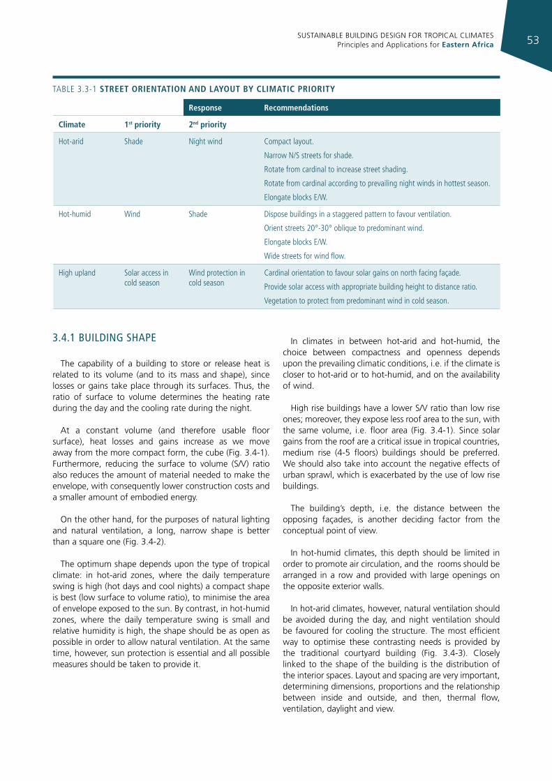
SUSTAINABLE BUILDING DESIGN FOR TROPICAL CLIMATES Principles and Applications for Eastern Africa 53
response recommendations
climate 1st priority 2nd priority
Hot-arid Shade Night wind Compact layout.
Narrow N/S streets for shade.
rotate from cardinal to increase street shading.
rotate from cardinal according to prevailing night winds in hottest season.
elongate blocks e/W.
Hot-humid Wind Shade Dispose buildings in a staggered pattern to favour ventilation.
Orient streets 20°-30° oblique to predominant wind.
elongate blocks e/W.
Wide streets for wind flow.
High upland Solar access in cold season
Wind protection in cold season
Cardinal orientation to favour solar gains on north facing façade.
Provide solar access with appropriate building height to distance ratio.
Vegetation to protect from predominant wind in cold season.
TABLe 3.3-1 street orIentatIon and layout by clImatIc prIorIty
3.4.1 buIldIng shape
The capability of a building to store or release heat is related to its volume (and to its mass and shape), since losses or gains take place through its surfaces. Thus, the ratio of surface to volume determines the heating rate during the day and the cooling rate during the night.
At a constant volume (and therefore usable floor surface), heat losses and gains increase as we move away from the more compact form, the cube (Fig. 3.4-1). Furthermore, reducing the surface to volume (S/V) ratio also reduces the amount of material needed to make the envelope, with consequently lower construction costs and a smaller amount of embodied energy.
On the other hand, for the purposes of natural lighting and natural ventilation, a long, narrow shape is better than a square one (Fig. 3.4-2).
The optimum shape depends upon the type of tropical climate: in hot-arid zones, where the daily temperature swing is high (hot days and cool nights) a compact shape is best (low surface to volume ratio), to minimise the area of envelope exposed to the sun. By contrast, in hot-humid zones, where the daily temperature swing is small and relative humidity is high, the shape should be as open as possible in order to allow natural ventilation. At the same time, however, sun protection is essential and all possible measures should be taken to provide it.
In climates in between hot-arid and hot-humid, the choice between compactness and openness depends upon the prevailing climatic conditions, i.e. if the climate is closer to hot-arid or to hot-humid, and on the availability of wind.
High rise buildings have a lower S/V ratio than low rise ones; moreover, they expose less roof area to the sun, with the same volume, i.e. floor area (Fig. 3.4-1). Since solar gains from the roof are a critical issue in tropical countries, medium rise (4-5 floors) buildings should be preferred. We should also take into account the negative effects of urban sprawl, which is exacerbated by the use of low rise buildings.
The building’s depth, i.e. the distance between the opposing façades, is another deciding factor from the conceptual point of view.
In hot-humid climates, this depth should be limited in order to promote air circulation, and the rooms should be arranged in a row and provided with large openings on the opposite exterior walls.
In hot-arid climates, however, natural ventilation should be avoided during the day, and night ventilation should be favoured for cooling the structure. The most efficient way to optimise these contrasting needs is provided by the traditional courtyard building (Fig. 3.4-3). Closely linked to the shape of the building is the distribution of the interior spaces. Layout and spacing are very important, determining dimensions, proportions and the relationship between inside and outside, and then, thermal flow, ventilation, daylight and view.
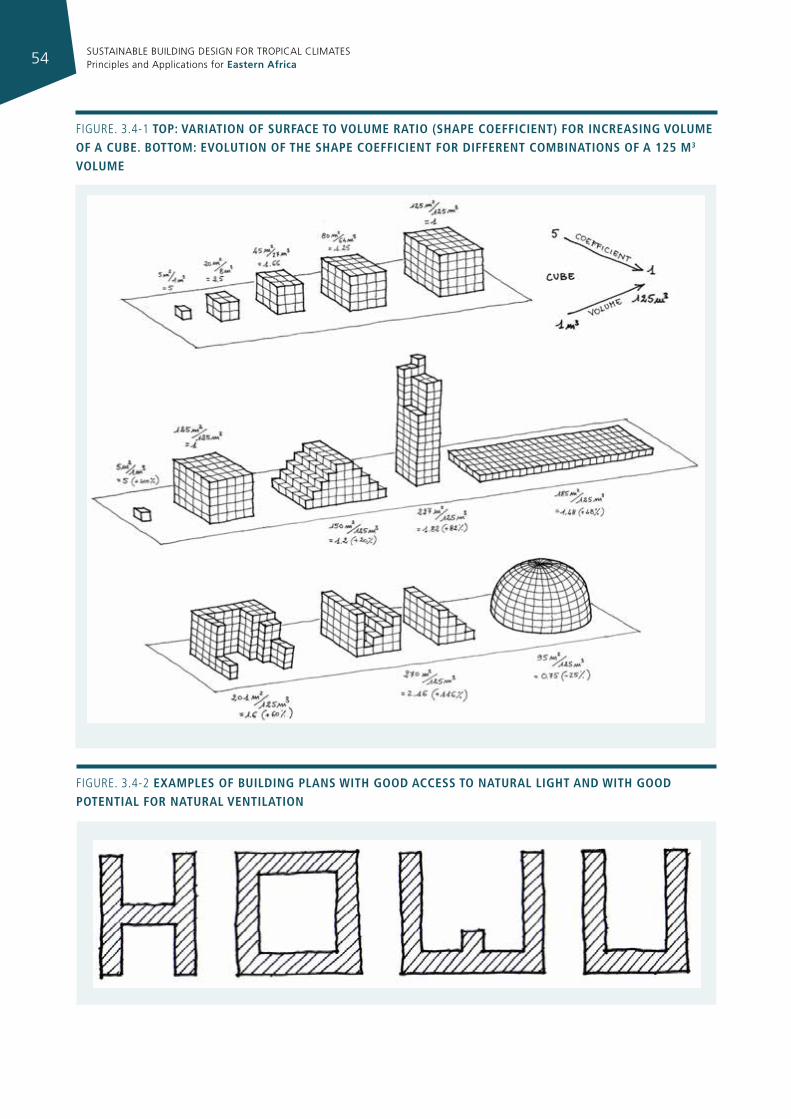
SUSTAINABLE BUILDING DESIGN FOR TROPICAL CLIMATES Principles and Applications for Eastern Africa54
Figure. 3.4-1 top: varIatIon of surface to volume ratIo (shape coeffIcIent) for IncreasIng volume of a cube. bottom: evolutIon of the shape coeffIcIent for dIfferent combInatIons of a 125 m3 volume
Figure. 3.4-2 examples of buIldIng plans WIth good access to natural lIght and WIth good potentIal for natural ventIlatIon
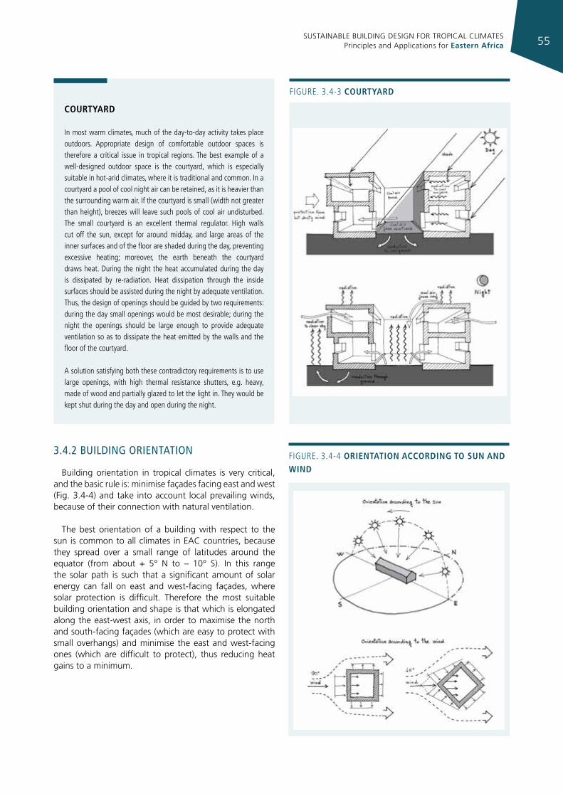
SUSTAINABLE BUILDING DESIGN FOR TROPICAL CLIMATES Principles and Applications for Eastern Africa 55
3.4.2 buIldIng orIenTaTIon
Building orientation in tropical climates is very critical, and the basic rule is: minimise façades facing east and west (Fig. 3.4-4) and take into account local prevailing winds, because of their connection with natural ventilation.
The best orientation of a building with respect to the sun is common to all climates in EAC countries, because they spread over a small range of latitudes around the equator (from about + 5° N to – 10° S). In this range the solar path is such that a significant amount of solar energy can fall on east and west-facing façades, where solar protection is difficult. Therefore the most suitable building orientation and shape is that which is elongated along the east-west axis, in order to maximise the north and south-facing façades (which are easy to protect with small overhangs) and minimise the east and west-facing ones (which are difficult to protect), thus reducing heat gains to a minimum.
Figure. 3.4-3 courtyard
courtyard
in most warm climates, much of the day-to-day activity takes place outdoors. Appropriate design of comfortable outdoor spaces is therefore a critical issue in tropical regions. The best example of a well-designed outdoor space is the courtyard, which is especially suitable in hot-arid climates, where it is traditional and common. in a courtyard a pool of cool night air can be retained, as it is heavier than the surrounding warm air. if the courtyard is small (width not greater than height), breezes will leave such pools of cool air undisturbed. The small courtyard is an excellent thermal regulator. High walls cut off the sun, except for around midday, and large areas of the inner surfaces and of the floor are shaded during the day, preventing excessive heating; moreover, the earth beneath the courtyard draws heat. During the night the heat accumulated during the day is dissipated by re-radiation. Heat dissipation through the inside surfaces should be assisted during the night by adequate ventilation. Thus, the design of openings should be guided by two requirements: during the day small openings would be most desirable; during the night the openings should be large enough to provide adequate ventilation so as to dissipate the heat emitted by the walls and the floor of the courtyard.
A solution satisfying both these contradictory requirements is to use large openings, with high thermal resistance shutters, e.g. heavy, made of wood and partially glazed to let the light in. They would be kept shut during the day and open during the night.
Figure. 3.4-4 orIentatIon accordIng to sun and WInd
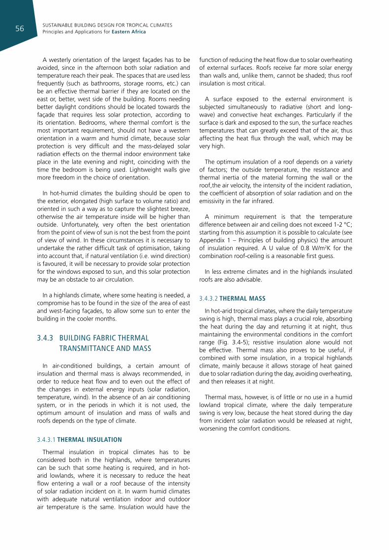
SUSTAINABLE BUILDING DESIGN FOR TROPICAL CLIMATES Principles and Applications for Eastern Africa56
A westerly orientation of the largest façades has to be avoided, since in the afternoon both solar radiation and temperature reach their peak. The spaces that are used less frequently (such as bathrooms, storage rooms, etc.) can be an effective thermal barrier if they are located on the east or, better, west side of the building. Rooms needing better daylight conditions should be located towards the façade that requires less solar protection, according to its orientation. Bedrooms, where thermal comfort is the most important requirement, should not have a western orientation in a warm and humid climate, because solar protection is very difficult and the mass-delayed solar radiation effects on the thermal indoor environment take place in the late evening and night, coinciding with the time the bedroom is being used. Lightweight walls give more freedom in the choice of orientation.
In hot-humid climates the building should be open to the exterior, elongated (high surface to volume ratio) and oriented in such a way as to capture the slightest breeze, otherwise the air temperature inside will be higher than outside. Unfortunately, very often the best orientation from the point of view of sun is not the best from the point of view of wind. In these circumstances it is necessary to undertake the rather difficult task of optimisation, taking into account that, if natural ventilation (i.e. wind direction) is favoured, it will be necessary to provide solar protection for the windows exposed to sun, and this solar protection may be an obstacle to air circulation.
In a highlands climate, where some heating is needed, a compromise has to be found in the size of the area of east and west-facing façades, to allow some sun to enter the building in the cooler months.
3.4.3 buIldIng fabrIc Thermal TransmITTance and mass
In air-conditioned buildings, a certain amount of insulation and thermal mass is always recommended, in order to reduce heat flow and to even out the effect of the changes in external energy inputs (solar radiation, temperature, wind). In the absence of an air conditioning system, or in the periods in which it is not used, the optimum amount of insulation and mass of walls and roofs depends on the type of climate.
3.4.3.1 thermal InsulatIon
Thermal insulation in tropical climates has to be considered both in the highlands, where temperatures can be such that some heating is required, and in hot-arid lowlands, where it is necessary to reduce the heat flow entering a wall or a roof because of the intensity of solar radiation incident on it. In warm humid climates with adequate natural ventilation indoor and outdoor air temperature is the same. Insulation would have the
function of reducing the heat flow due to solar overheating of external surfaces. Roofs receive far more solar energy than walls and, unlike them, cannot be shaded; thus roof insulation is most critical.
A surface exposed to the external environment is subjected simultaneously to radiative (short and long-wave) and convective heat exchanges. Particularly if the surface is dark and exposed to the sun, the surface reaches temperatures that can greatly exceed that of the air, thus affecting the heat flux through the wall, which may be very high.
The optimum insulation of a roof depends on a variety of factors; the outside temperature, the resistance and thermal inertia of the material forming the wall or the roof,the air velocity, the intensity of the incident radiation, the coefficient of absorption of solar radiation and on the emissivity in the far infrared.
A minimum requirement is that the temperature difference between air and ceiling does not exceed 1-2 °C; starting from this assumption it is possible to calculate (see Appendix 1 – Principles of building physics) the amount of insulation required. A U value of 0.8 W/m2K for the combination roof-ceiling is a reasonable first guess.
In less extreme climates and in the highlands insulated roofs are also advisable.
3.4.3.2 thermal mass
In hot-arid tropical climates, where the daily temperature swing is high, thermal mass plays a crucial role, absorbing the heat during the day and returning it at night, thus maintaining the environmental conditions in the comfort range (Fig. 3.4-5); resistive insulation alone would not be effective. Thermal mass also proves to be useful, if combined with some insulation, in a tropical highlands climate, mainly because it allows storage of heat gained due to solar radiation during the day, avoiding overheating, and then releases it at night.
Thermal mass, however, is of little or no use in a humid lowland tropical climate, where the daily temperature swing is very low, because the heat stored during the day from incident solar radiation would be released at night, worsening the comfort conditions.
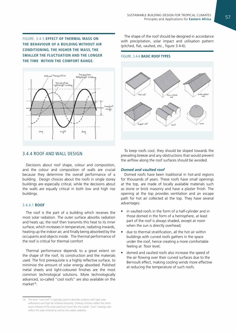
SUSTAINABLE BUILDING DESIGN FOR TROPICAL CLIMATES Principles and Applications for Eastern Africa 57
3.4.4 roof and wall desIgn
Decisions about roof shape, colour and composition, and the colour and composition of walls are crucial because they determine the overall performance of a building. Design choices about the roofs in single storey buildings are especially critical, while the decisions about the walls are equally critical in both low and high rise buildings.
3.4.4.1 roof
The roof is the part of a building which receives the most solar radiation. The outer surface absorbs radiation and heats up; the roof then transmits this heat to its inner surface, which increases in temperature, radiating inwards, heating up the indoor air, and finally being absorbed by the occupants and objects inside. The thermal performance of the roof is critical for thermal comfort
Thermal performance depends to a great extent on the shape of the roof, its construction and the materials used. The first prerequisite is a highly reflective surface, to minimise the amount of solar energy absorbed. Polished metal sheets and light-coloured finishes are the most common technological solutions. More technologically advanced, so-called “cool roofs” are also available on the market18.
18 The term “cool roof” is typically used to describe surfaces with high solar reflectance and high far infrared emissivity. Ordinary finishes reflect the short-wave infrared of the solar spectrum much like the visible; “cool” coatings also reflect the solar infrared as well as the visible radiation.
The shape of the roof should be designed in accordance with precipitation, solar impact and utilisation pattern (pitched, flat, vaulted, etc., figure 3.4-6).
To keep roofs cool, they should be sloped towards the prevailing breeze and any obstructions that would prevent the airflow along the roof surfaces should be avoided.
Domed and vaulted roofDomed roofs have been traditional in hot-arid regions
for thousands of years. These roofs have small openings at the top, are made of locally available materials such as stone or brick masonry and have a plaster finish. The opening at the top provides ventilation and an escape path for hot air collected at the top. They have several advantages:
• in vaulted roofs in the form of a half-cylinder and in those domed in the form of a hemisphere, at least part of the roof is always shaded, except at noon when the sun is directly overhead;
• due to thermal stratification, all the hot air within buildings with curved roofs gathers in the space under the roof, hence creating a more comfortable feeling at floor level;
• domed and vaulted roofs also increase the speed of the air flowing over their curved surfaces due to the Bernoulli effect, making cooling winds more effective at reducing the temperature of such roofs.
Figure. 3.4-5 effect of thermal mass on the behavIour of a buIldIng WIthout aIr condItIonIng. the hIgher the mass, the smaller the fluctuatIon and the longer the tIme WIthIn the comfort range.
Figure. 3.4-6 basIc roof types
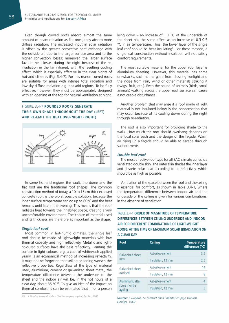
SUSTAINABLE BUILDING DESIGN FOR TROPICAL CLIMATES Principles and Applications for Eastern Africa58
Even though curved roofs absorb almost the same amount of beam radiation as flat ones, they absorb more diffuse radiation. The increased input in solar radiation is offset by the greater convective heat exchange with the outside air, due to the larger surface area and to the higher convection losses; moreover, the larger surface favours heat losses during the night because of the re-irradiation in the far infrared, with the resulting cooling effect, which is especially effective in the clear nights of hot-arid climates (Fig. 3.4-7). For this reason curved roofs are suitable for areas with intense total radiation and low sky diffuse radiation e.g. hot-arid regions. To be fully effective, however, they must be appropriately designed with an opening at the top for natural ventilation at night.
In some hot-arid regions the vault, the dome and the flat roof are the traditional roof shapes. The common construction method of today, a 10 to 15 cm thick exposed concrete roof, is the worst possible solution, because the inner surface temperature can go up to 60°C and the heat remains until late in the evening. This means that the roof radiates heat towards the inhabited space, creating a very uncomfortable environment. The choice of material used and its thickness are therefore as important as the shape.
Single leaf roof Most common in hot-humid climates, the single leaf
roof should be made of lightweight materials with low thermal capacity and high reflectivity. Metallic and light-coloured surfaces have the best reflectivity. Painting the surface in light colours, e.g. a coat of whitewash applied yearly, is an economical method of increasing reflectivity. It must not be forgotten that soiling or ageing worsen the reflective properties. Regardless of the type of material used, aluminium, cement or galvanized sheet metal, the temperature difference between the underside of the sheet and the indoor air will be, in the hot hours of a clear day, about 35 °C19. To give an idea of the impact on thermal comfort, it can be estimated that – for a person
19 J. Dreyfus, Le comfort dans l’habitat en pays tropical, Eyrolles, 1960
lying down – an increase of 1 °C of the underside of the sheet has the same effect as an increase of 0.3-0.5 °C in air temperature. Thus, the lower layer of the single leaf roof should be heat insulating2. For these reasons, a single leaf construction without insulation will not satisfy comfort requirements.
The most suitable material for the upper roof layer is aluminium sheeting. However, this material has some drawbacks, such as the glare from dazzling sunlight and the noise from rain, wind or other materials striking it (twigs, fruit, etc.). Even the sound of animals (birds, small animals) walking across the upper roof surface can cause a noticeable disturbance.
Another problem that may arise if a roof made of light material is not insulated below is the condensation that may occur because of its cooling down during the night through re-radiation.
The roof is also important for providing shade to the walls. How much the roof should overhang depends on the local solar path and the design of the façade. Warm air rising up a façade should be able to escape through suitable vents.
Double leaf roofThe most effective roof type for all EAC climate zones is a
ventilated double skin. The outer skin shades the inner layer and absorbs solar heat according to its reflectivity, which should be as high as possible.
Ventilation of the space between the roof and the ceiling is essential for comfort, as shown in Table 3.4-1, where the temperature difference between indoor air and the underside of the ceiling is given for various combinations, in the absence of ventilation.
Figure. 3.4-7 rounded roofs generate theIr oWn shade throughout the day (left) and re-emIt the heat overnIght (rIght)
roof ceiling temperature difference (°c)
galvanised sheet, new
Asbestos-cement 3.5
insulation, 12 mm 2.5
galvanised sheet, oxidised
Asbestos-cement 14
insulation, 12 mm 8
Aluminium, after some months ageing
Asbestos-cement 4
insulation, 12 mm 3
TABLe 3.4-1 order of magnItude of temperature dIfferences betWeen ceIlIng undersIde and Indoor aIr for dIfferent combInatIons of lIght-WeIght roofs, at the tIme of maxImum solar IrradIatIon on a clear day
Source: J. Dreyfus, Le comfort dans l’habitat en pays tropical, Eyrolles, 1960
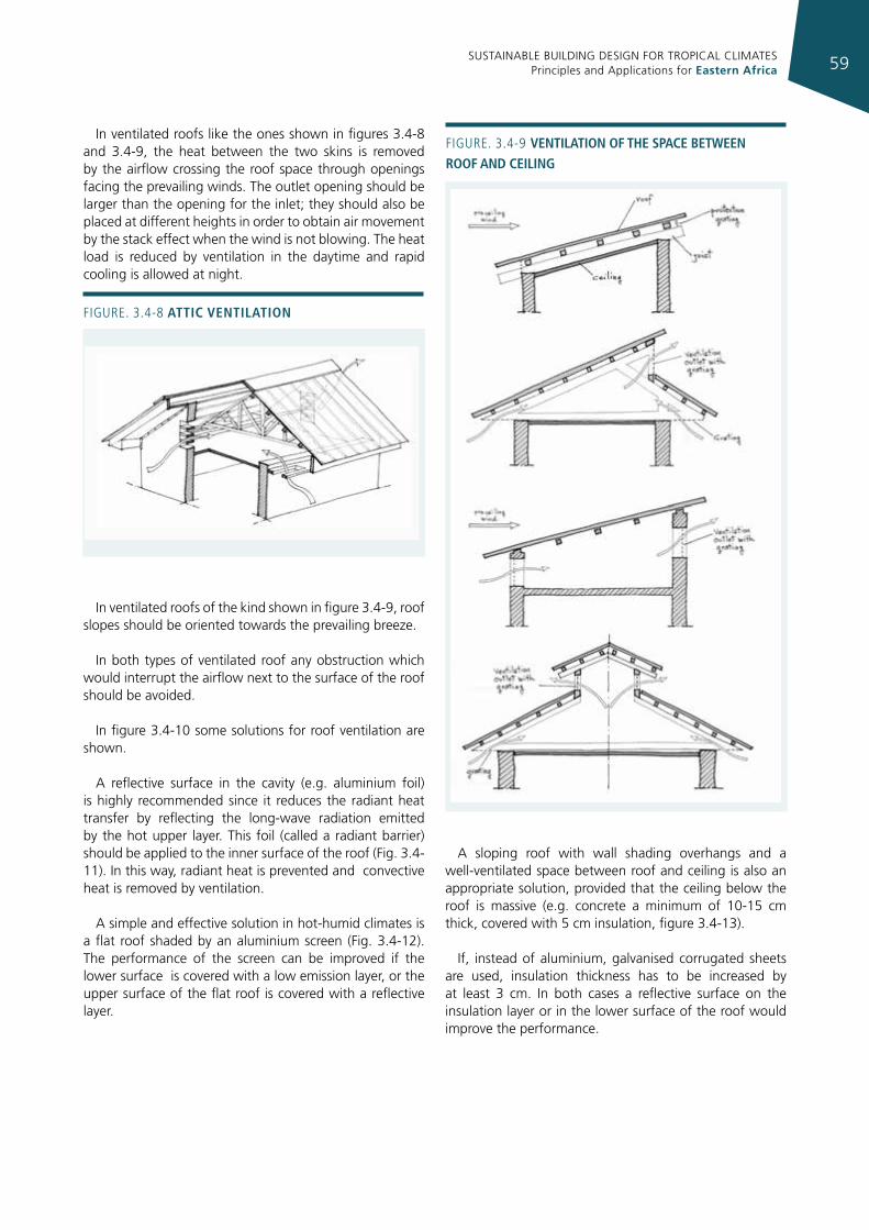
SUSTAINABLE BUILDING DESIGN FOR TROPICAL CLIMATES Principles and Applications for Eastern Africa 59
In ventilated roofs like the ones shown in figures 3.4-8 and 3.4-9, the heat between the two skins is removed by the airflow crossing the roof space through openings facing the prevailing winds. The outlet opening should be larger than the opening for the inlet; they should also be placed at different heights in order to obtain air movement by the stack effect when the wind is not blowing. The heat load is reduced by ventilation in the daytime and rapid cooling is allowed at night.
In ventilated roofs of the kind shown in figure 3.4-9, roof slopes should be oriented towards the prevailing breeze.
In both types of ventilated roof any obstruction which would interrupt the airflow next to the surface of the roof should be avoided.
In figure 3.4-10 some solutions for roof ventilation are shown.
A reflective surface in the cavity (e.g. aluminium foil) is highly recommended since it reduces the radiant heat transfer by reflecting the long-wave radiation emitted by the hot upper layer. This foil (called a radiant barrier) should be applied to the inner surface of the roof (Fig. 3.4-11). In this way, radiant heat is prevented and convective heat is removed by ventilation.
A simple and effective solution in hot-humid climates is a flat roof shaded by an aluminium screen (Fig. 3.4-12). The performance of the screen can be improved if the lower surface is covered with a low emission layer, or the upper surface of the flat roof is covered with a reflective layer.
A sloping roof with wall shading overhangs and a well-ventilated space between roof and ceiling is also an appropriate solution, provided that the ceiling below the roof is massive (e.g. concrete a minimum of 10-15 cm thick, covered with 5 cm insulation, figure 3.4-13).
If, instead of aluminium, galvanised corrugated sheets are used, insulation thickness has to be increased by at least 3 cm. In both cases a reflective surface on the insulation layer or in the lower surface of the roof would improve the performance.
Figure. 3.4-8 attIc ventIlatIon
Figure. 3.4-9 ventIlatIon of the space betWeen roof and ceIlIng
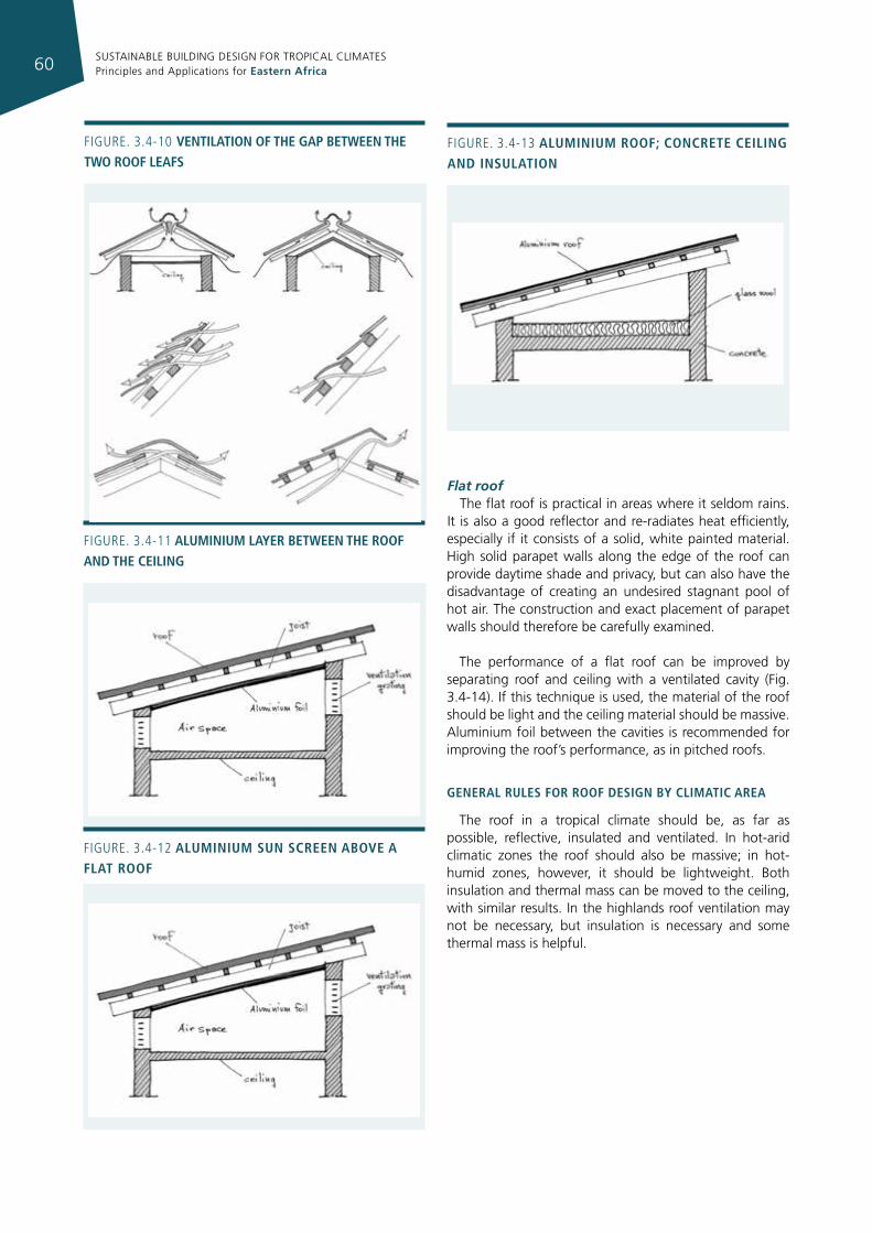
SUSTAINABLE BUILDING DESIGN FOR TROPICAL CLIMATES Principles and Applications for Eastern Africa60
Figure. 3.4-11 alumInIum layer betWeen the roof and the ceIlIng
Figure. 3.4-12 alumInIum sun screen above a flat roof
Figure. 3.4-13 alumInIum roof; concrete ceIlIng and InsulatIon
Flat roofThe flat roof is practical in areas where it seldom rains.
It is also a good reflector and re-radiates heat efficiently, especially if it consists of a solid, white painted material. High solid parapet walls along the edge of the roof can provide daytime shade and privacy, but can also have the disadvantage of creating an undesired stagnant pool of hot air. The construction and exact placement of parapet walls should therefore be carefully examined.
The performance of a flat roof can be improved by separating roof and ceiling with a ventilated cavity (Fig. 3.4-14). If this technique is used, the material of the roof should be light and the ceiling material should be massive. Aluminium foil between the cavities is recommended for improving the roof’s performance, as in pitched roofs.
general rules for roof desIgn by clImatIc area
The roof in a tropical climate should be, as far as possible, reflective, insulated and ventilated. In hot-arid climatic zones the roof should also be massive; in hot-humid zones, however, it should be lightweight. Both insulation and thermal mass can be moved to the ceiling, with similar results. In the highlands roof ventilation may not be necessary, but insulation is necessary and some thermal mass is helpful.
Figure. 3.4-10 ventIlatIon of the gap betWeen the tWo roof leafs
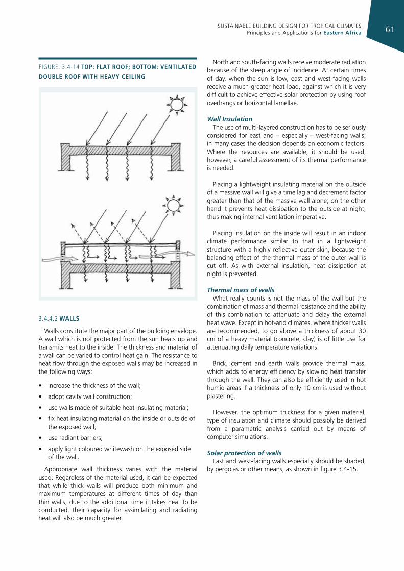
SUSTAINABLE BUILDING DESIGN FOR TROPICAL CLIMATES Principles and Applications for Eastern Africa 61
3.4.4.2 Walls
Walls constitute the major part of the building envelope. A wall which is not protected from the sun heats up and transmits heat to the inside. The thickness and material of a wall can be varied to control heat gain. The resistance to heat flow through the exposed walls may be increased in the following ways:
• increase the thickness of the wall;
• adopt cavity wall construction;
• use walls made of suitable heat insulating material;
• fix heat insulating material on the inside or outside of the exposed wall;
• use radiant barriers;
• apply light coloured whitewash on the exposed side of the wall.
Appropriate wall thickness varies with the material used. Regardless of the material used, it can be expected that while thick walls will produce both minimum and maximum temperatures at different times of day than thin walls, due to the additional time it takes heat to be conducted, their capacity for assimilating and radiating heat will also be much greater.
North and south-facing walls receive moderate radiation because of the steep angle of incidence. At certain times of day, when the sun is low, east and west-facing walls receive a much greater heat load, against which it is very difficult to achieve effective solar protection by using roof overhangs or horizontal lamellae.
Wall InsulationThe use of multi-layered construction has to be seriously
considered for east and – especially – west-facing walls; in many cases the decision depends on economic factors. Where the resources are available, it should be used; however, a careful assessment of its thermal performance is needed.
Placing a lightweight insulating material on the outside of a massive wall will give a time lag and decrement factor greater than that of the massive wall alone; on the other hand it prevents heat dissipation to the outside at night, thus making internal ventilation imperative.
Placing insulation on the inside will result in an indoor climate performance similar to that in a lightweight structure with a highly reflective outer skin, because the balancing effect of the thermal mass of the outer wall is cut off. As with external insulation, heat dissipation at night is prevented.
Thermal mass of wallsWhat really counts is not the mass of the wall but the
combination of mass and thermal resistance and the ability of this combination to attenuate and delay the external heat wave. Except in hot-arid climates, where thicker walls are recommended, to go above a thickness of about 30 cm of a heavy material (concrete, clay) is of little use for attenuating daily temperature variations.
Brick, cement and earth walls provide thermal mass, which adds to energy efficiency by slowing heat transfer through the wall. They can also be efficiently used in hot humid areas if a thickness of only 10 cm is used without plastering.
However, the optimum thickness for a given material, type of insulation and climate should possibly be derived from a parametric analysis carried out by means of computer simulations.
Solar protection of walls East and west-facing walls especially should be shaded,
by pergolas or other means, as shown in figure 3.4-15.
Figure. 3.4-14 top: flat roof; bottom: ventIlated double roof WIth heavy ceIlIng
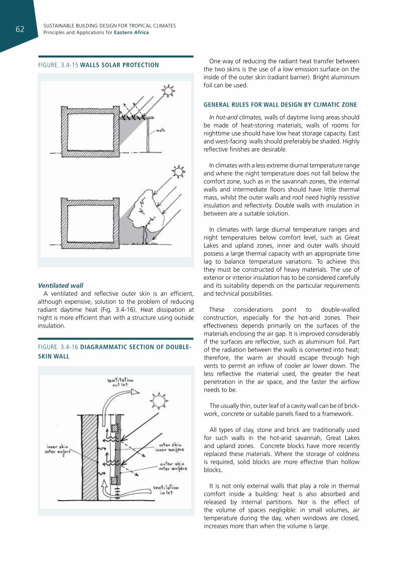
SUSTAINABLE BUILDING DESIGN FOR TROPICAL CLIMATES Principles and Applications for Eastern Africa62
Ventilated wallA ventilated and reflective outer skin is an efficient,
although expensive, solution to the problem of reducing radiant daytime heat (Fig. 3.4-16). Heat dissipation at night is more efficient than with a structure using outside insulation.
One way of reducing the radiant heat transfer between the two skins is the use of a low emission surface on the inside of the outer skin (radiant barrier). Bright aluminium foil can be used.
general rules for Wall desIgn by clImatIc zone
In hot-arid climates, walls of daytime living areas should be made of heat-storing materials; walls of rooms for nighttime use should have low heat storage capacity. East and west-facing walls should preferably be shaded. Highly reflective finishes are desirable.
In climates with a less extreme diurnal temperature range and where the night temperature does not fall below the comfort zone, such as in the savannah zones, the internal walls and intermediate floors should have little thermal mass, whilst the outer walls and roof need highly resistive insulation and reflectivity. Double walls with insulation in between are a suitable solution.
In climates with large diurnal temperature ranges and night temperatures below comfort level, such as Great Lakes and upland zones, inner and outer walls should possess a large thermal capacity with an appropriate time lag to balance temperature variations. To achieve this they must be constructed of heavy materials. The use of exterior or interior insulation has to be considered carefully and its suitability depends on the particular requirements and technical possibilities.
These considerations point to double-walled construction, especially for the hot-arid zones. Their effectiveness depends primarily on the surfaces of the materials enclosing the air gap. It is improved considerably if the surfaces are reflective, such as aluminium foil. Part of the radiation between the walls is converted into heat; therefore, the warm air should escape through high vents to permit an inflow of cooler air lower down. The less reflective the material used, the greater the heat penetration in the air space, and the faster the airflow needs to be.
The usually thin, outer leaf of a cavity wall can be of brick-work, concrete or suitable panels fixed to a framework.
All types of clay, stone and brick are traditionally used for such walls in the hot-arid savannah, Great Lakes and upland zones. Concrete blocks have more recently replaced these materials. Where the storage of coldness is required, solid blocks are more effective than hollow blocks.
It is not only external walls that play a role in thermal comfort inside a building: heat is also absorbed and released by internal partitions. Nor is the effect of the volume of spaces negligible: in small volumes, air temperature during the day, when windows are closed, increases more than when the volume is large.
Figure. 3.4-16 dIagrammatIc sectIon of double-skIn Wall
Figure. 3.4-15 Walls solar protectIon
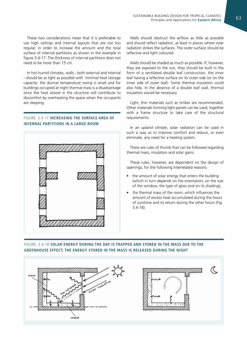
SUSTAINABLE BUILDING DESIGN FOR TROPICAL CLIMATES Principles and Applications for Eastern Africa 63
These two considerations mean that it is preferable to use high ceilings and internal layouts that are not too regular, in order to increase the amount and the total surface of internal partitions as shown in the example in figure 3.4-17. The thickness of internal partitions does not need to be more than 15 cm.
In hot-humid climates, walls - both external and internal - should be as light as possible with minimal heat storage capacity: the diurnal temperature swing is small and for buildings occupied at night thermal mass is a disadvantage since the heat stored in the structure will contribute to discomfort by overheating the space when the occupants are sleeping.
Walls should obstruct the airflow as little as possible and should reflect radiation, at least in places where solar radiation strikes the surfaces. The outer surface should be reflective and light coloured.
Walls should be shaded as much as possible. If, however, they are exposed to the sun, they should be built in the form of a ventilated double leaf construction, the inner leaf having a reflective surface on its outer side (or on the inner side of outer leaf). Some thermal insulation could also help. In the absence of a double leaf wall, thermal insulation would be necessary.
Light, thin materials such as timber are recommended. Other materials forming light panels can be used, together with a frame structure to take care of the structural requirements.
In an upland climate, solar radiation can be used in such a way as to improve comfort and reduce, or even eliminate, any need for a heating system.
There are rules of thumb that can be followed regarding thermal mass, insulation and solar gains.
These rules, however, are dependent on the design of openings, for the following interrelated reasons:
• the amount of solar energy that enters the building (which in turn depends on the orientation, on the size of the window, the type of glass and on its shading);
• the thermal mass of the room, which influences the amount of excess heat accumulated during the hours of sunshine and its return during the other hours (Fig. 3.4-18).
Figure. 3.4-17 IncreasIng the surface area of Internal partItIons In a large room
Figure. 3.4-18 solar energy durIng the day Is trapped and stored In the mass due to the greenhouse effect; the energy stored In the mass Is released durIng the nIght
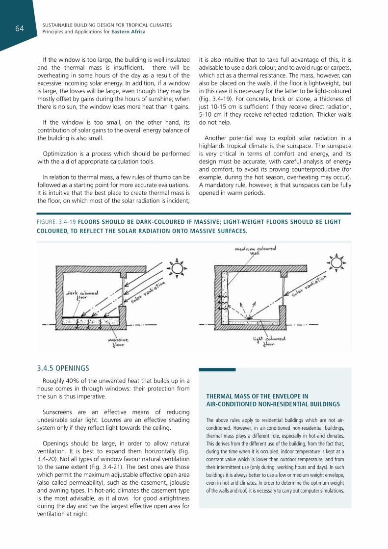
SUSTAINABLE BUILDING DESIGN FOR TROPICAL CLIMATES Principles and Applications for Eastern Africa64
Figure. 3.4-19 floors should be dark-coloured If massIve; lIght-WeIght floors should be lIght coloured, to reflect the solar radIatIon onto massIve surfaces.
3.4.5 openIngs
Roughly 40% of the unwanted heat that builds up in a house comes in through windows: their protection from the sun is thus imperative.
Sunscreens are an effective means of reducing undesirable solar light. Louvres are an effective shading system only if they reflect light towards the ceiling.
Openings should be large, in order to allow natural ventilation. It is best to expand them horizontally (Fig. 3.4-20). Not all types of window favour natural ventilation to the same extent (Fig. 3.4-21). The best ones are those which permit the maximum adjustable effective open area (also called permeability), such as the casement, jalousie and awning types. In hot-arid climates the casement type is the most advisable, as it allows for good airtightness during the day and has the largest effective open area for ventilation at night.
thermal mass of the envelope In aIr-condItIoned non-resIdentIal buIldIngs
The above rules apply to residential buildings which are not air-conditioned. However, in air-conditioned non-residential buildings, thermal mass plays a different role, especially in hot-arid climates. This derives from the different use of the building, from the fact that, during the time when it is occupied, indoor temperature is kept at a constant value which is lower than outdoor temperature, and from their intermittent use (only during working hours and days). in such buildings it is always better to use a low or medium weight envelope, even in hot-arid climates. in order to determine the optimum weight of the walls and roof, it is necessary to carry out computer simulations.
If the window is too large, the building is well insulated and the thermal mass is insufficient, there will be overheating in some hours of the day as a result of the excessive incoming solar energy. In addition, if a window is large, the losses will be large, even though they may be mostly offset by gains during the hours of sunshine; when there is no sun, the window loses more heat than it gains.
If the window is too small, on the other hand, its contribution of solar gains to the overall energy balance of the building is also small.
Optimization is a process which should be performed with the aid of appropriate calculation tools.
In relation to thermal mass, a few rules of thumb can be followed as a starting point for more accurate evaluations. It is intuitive that the best place to create thermal mass is the floor, on which most of the solar radiation is incident;
it is also intuitive that to take full advantage of this, it is advisable to use a dark colour, and to avoid rugs or carpets, which act as a thermal resistance. The mass, however, can also be placed on the walls, if the floor is lightweight, but in this case it is necessary for the latter to be light-coloured (Fig. 3.4-19). For concrete, brick or stone, a thickness of just 10-15 cm is sufficient if they receive direct radiation, 5-10 cm if they receive reflected radiation. Thicker walls do not help.
Another potential way to exploit solar radiation in a highlands tropical climate is the sunspace. The sunspace is very critical in terms of comfort and energy, and its design must be accurate, with careful analysis of energy and comfort, to avoid its proving counterproductive (for example, during the hot season, overheating may occur). A mandatory rule, however, is that sunspaces can be fully opened in warm periods.
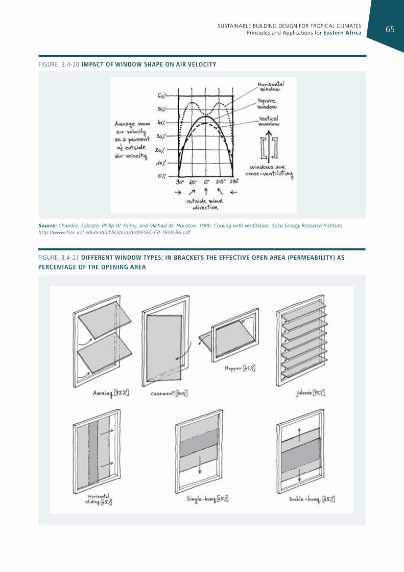
SUSTAINABLE BUILDING DESIGN FOR TROPICAL CLIMATES Principles and Applications for Eastern Africa 65
Figure. 3.4-20 Impact of WIndoW shape on aIr velocIty
Source: Chandra, Subrato, Philip W. Fairey, and Michael M. Houston. 1986. Cooling with ventilation, Solar Energy Research Institute. http://www.fsec.ucf.edu/en/publications/pdf/FSEC‐CR‐1658‐86.pdf
Figure. 3.4-21 dIfferent WIndoW types; In brackets the effectIve open area (permeabIlIty) as percentage of the openIng area
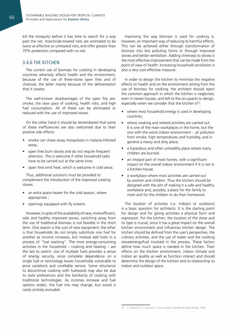
SUSTAINABLE BUILDING DESIGN FOR TROPICAL CLIMATES Principles and Applications for Eastern Africa66
kill the mosquito before it has time to search for a way past the net. Insecticide-treated nets are estimated to be twice as effective as untreated nets, and offer greater than 70% protection compared with no net.
3.4.6 The kITchen
The current use of biomass for cooking in developing countries adversely affects health and the environment, because of the use of three-stone open fires and of charcoal, the latter mainly because of the deforestation that it creates.
The well-known disadvantages of the open fire are: smoke; the slow pace of cooking; health risks; and high fuel consumption. All of these can be eliminated or reduced with the use of improved stoves.
On the other hand it should be remembered that some of these inefficiencies are also welcomed due to their positive side effects:
• smoke can chase away mosquitoes in malaria-infested areas;
• open fires burn slowly and do not require frequent attention. This is welcome if other household tasks have to be carried out at the same time;
• open fires emit heat, which is welcome in cold areas.
Thus, additional solutions must be provided to complement the introduction of the improved cooking stoves:
• an extra space heater for the cold season, where appropriate ;
• openings equipped with fly screens.
However, in spite of the availability of new, more efficient, safe and healthy improved stoves, switching away from the use of traditional biomass is not feasible in the short term. One reason is the cost of new equipment; the other is that households do not simply substitute one fuel for another as income increases, but instead add fuels in a process of “fuel stacking”. The most energy-consuming activities in the household – cooking and heating – are the last to switch. Use of multiple fuels provides a sense of energy security, since complete dependence on a single fuel or technology leaves households vulnerable to price variations and unreliable service. Some reluctance to discontinue cooking with fuelwood may also be due to taste preferences and the familiarity of cooking with traditional technologies. As incomes increase and fuel options widen, the fuel mix may change, but wood is rarely entirely excluded.
Improving the way biomass is used for cooking is, however, an important way of reducing its harmful effects. This can be achieved either through transformation of biomass into less polluting forms or through improved stoves and better ventilation. Adding chimneys to stoves is the most effective improvement that can be made from the point of view of health. Increasing household ventilation is also a very cost-effective measure.
In order to design the kitchen to minimise the negative effects on health and on the environment arising from the use of biomass for cooking, the architect should reject the common approach in which the kitchen is neglected, even in newer houses, and left to the occupants to design, especially when we consider that the kitchen is20:
• where most household energy is used in developing countries;
• where cooking and related activities are carried out. It is one of the main workplaces in the home, but the one with the worst indoor environment - air pollution from smoke, high temperatures and humidity, and in general a messy and dirty place;
• a hazardous and often unhealthy place where many children are burned;
• an integral part of most homes, with a significant impact on the overall indoor environment if it is not in a kitchen-house;
• a workplace where most activities are carried out by women and children. Thus the kitchen should be designed with the aim of making it a safe and healthy workplace and, possibly, a place for the family to meet and for the children to do their homework.
The location of activities (i.e. indoors or outdoors) is a basic question for architects. It is the starting point for design and for giving activities a physical form and expression. For the kitchen, the location of the stove and its type is crucial, since it has a great impact on the overall kitchen environment and influences kitchen design. The kitchen should be defined from the user’s perspective, the culinary activities, and the use of water and the cooking stove/energy/fuel involved in the process. These factors define how much space is needed in the kitchen. Their effects on the kitchen environment, indoor climate and indoor air quality as well as function interact and should determine the design of the kitchen and its relationship to indoor and outdoor space.
20 B. Westhoff, D. Germann, Stove Images, Brandes & Apsel Verlag, 1995
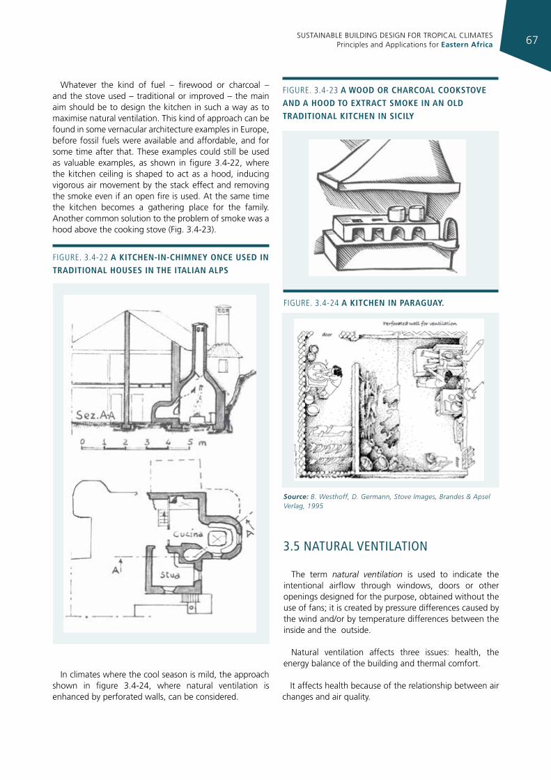
SUSTAINABLE BUILDING DESIGN FOR TROPICAL CLIMATES Principles and Applications for Eastern Africa 67
Whatever the kind of fuel – firewood or charcoal – and the stove used – traditional or improved – the main aim should be to design the kitchen in such a way as to maximise natural ventilation. This kind of approach can be found in some vernacular architecture examples in Europe, before fossil fuels were available and affordable, and for some time after that. These examples could still be used as valuable examples, as shown in figure 3.4-22, where the kitchen ceiling is shaped to act as a hood, inducing vigorous air movement by the stack effect and removing the smoke even if an open fire is used. At the same time the kitchen becomes a gathering place for the family. Another common solution to the problem of smoke was a hood above the cooking stove (Fig. 3.4-23).
In climates where the cool season is mild, the approach shown in figure 3.4-24, where natural ventilation is enhanced by perforated walls, can be considered.
3.5 naTural venTIlaTIon
The term natural ventilation is used to indicate the intentional airflow through windows, doors or other openings designed for the purpose, obtained without the use of fans; it is created by pressure differences caused by the wind and/or by temperature differences between the inside and the outside.
Natural ventilation affects three issues: health, the energy balance of the building and thermal comfort.
It affects health because of the relationship between air changes and air quality.
Figure. 3.4-22 a kItchen-In-chImney once used In tradItIonal houses In the ItalIan alps
Figure. 3.4-23 a Wood or charcoal cookstove and a hood to extract smoke In an old tradItIonal kItchen In sIcIly
Figure. 3.4-24 a kItchen In paraguay.
Source: B. Westhoff, D. Germann, Stove Images, Brandes & Apsel Verlag, 1995
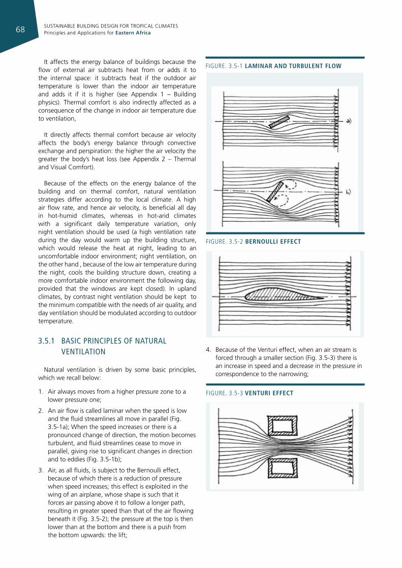
SUSTAINABLE BUILDING DESIGN FOR TROPICAL CLIMATES Principles and Applications for Eastern Africa68
It affects the energy balance of buildings because the flow of external air subtracts heat from or adds it to the internal space: it subtracts heat if the outdoor air temperature is lower than the indoor air temperature and adds it if it is higher (see Appendix 1 – Building physics). Thermal comfort is also indirectly affected as a consequence of the change in indoor air temperature due to ventilation,
It directly affects thermal comfort because air velocity affects the body’s energy balance through convective exchange and perspiration: the higher the air velocity the greater the body’s heat loss (see Appendix 2 – Thermal and Visual Comfort).
Because of the effects on the energy balance of the building and on thermal comfort, natural ventilation strategies differ according to the local climate. A high air flow rate, and hence air velocity, is beneficial all day in hot-humid climates, whereas in hot-arid climates with a significant daily temperature variation, only night ventilation should be used (a high ventilation rate during the day would warm up the building structure, which would release the heat at night, leading to an uncomfortable indoor environment; night ventilation, on the other hand , because of the low air temperature during the night, cools the building structure down, creating a more comfortable indoor environment the following day, provided that the windows are kept closed). In upland climates, by contrast night ventilation should be kept to the minimum compatible with the needs of air quality, and day ventilation should be modulated according to outdoor temperature.
3.5.1 basIc prIncIples of naTural venTIlaTIon
Natural ventilation is driven by some basic principles, which we recall below:
1. Air always moves from a higher pressure zone to a lower pressure one;
2. An air flow is called laminar when the speed is low and the fluid streamlines all move in parallel (Fig. 3.5-1a); When the speed increases or there is a pronounced change of direction, the motion becomes turbulent, and fluid streamlines cease to move in parallel, giving rise to significant changes in direction and to eddies (Fig. 3.5-1b);
3. Air, as all fluids, is subject to the Bernoulli effect, because of which there is a reduction of pressure when speed increases; this effect is exploited in the wing of an airplane, whose shape is such that it forces air passing above it to follow a longer path, resulting in greater speed than that of the air flowing beneath it (Fig. 3.5-2); the pressure at the top is then lower than at the bottom and there is a push from the bottom upwards: the lift;
4. Because of the Venturi effect, when an air stream is forced through a smaller section (Fig. 3.5-3) there is an increase in speed and a decrease in the pressure in correspondence to the narrowing;
Figure. 3.5-1 lamInar and turbulent floW
Figure. 3.5-2 bernoullI effect
Figure. 3.5-3 venturI effect
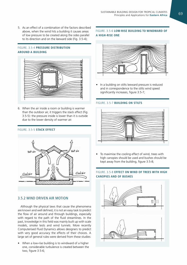
SUSTAINABLE BUILDING DESIGN FOR TROPICAL CLIMATES Principles and Applications for Eastern Africa 69
5. As an effect of a combination of the factors described above, when the wind hits a building it causes areas of low pressure to be created along the sides parallel to its direction and on the leeward side (Fig. 3.5-4);
6. When the air inside a room or building is warmer than the outdoor air, it triggers the stack effect (Fig. 3.5-5): the pressure inside is lower than it is outside due to the lower density of warmer air.
3.5.2 wInd drIven aIr moTIon
Although the physical laws that cause the phenomena are known and well defined, it is not an easy task to predict the flow of air around and through buildings, especially with regard to the path of the fluid streamlines. In the past, knowledge in this field was mainly built up with scale models, smoke tests and wind tunnels. More recently Computerised Fluid Dynamics allows designers to predict with very good accuracy the effects of their choices. A large set of general rules were derived from these studies:
• When a low-rise building is to windward of a higher one, considerable turbulence is created between the two, figure 3.5-6;
• In a building on stilts leeward pressure is reduced and in correspondence to the stilts wind speed significantly increases, figure 3.5-7;
• To maximise the cooling effect of wind, trees with high canopies should be used and bushes should be kept away from the building, figure 3.5-8;
Figure. 3.5-7 buIldIng on stIlts
Figure. 3.5-4 pressure dIstrIbutIon around a buIldIng
Figure. 3.5-5 stack effect
Figure. 3.5-6 loW-rIse buIldIng to WIndWard of a hIgh-rIse one
Figure. 3.5-8 effect on WInd of trees WIth hIgh canopIes and of bushes
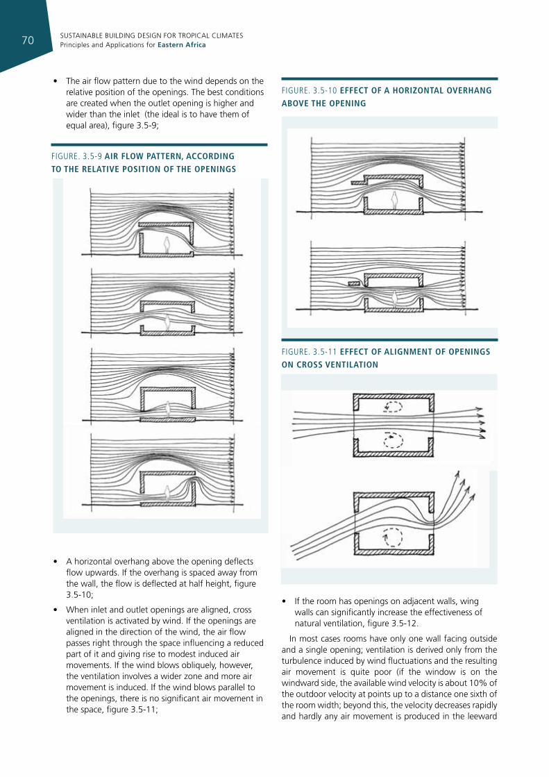
SUSTAINABLE BUILDING DESIGN FOR TROPICAL CLIMATES Principles and Applications for Eastern Africa70
• The air flow pattern due to the wind depends on the relative position of the openings. The best conditions are created when the outlet opening is higher and wider than the inlet (the ideal is to have them of equal area), figure 3.5-9;
• A horizontal overhang above the opening deflects flow upwards. If the overhang is spaced away from the wall, the flow is deflected at half height, figure 3.5-10;
• When inlet and outlet openings are aligned, cross ventilation is activated by wind. If the openings are aligned in the direction of the wind, the air flow passes right through the space influencing a reduced part of it and giving rise to modest induced air movements. If the wind blows obliquely, however, the ventilation involves a wider zone and more air movement is induced. If the wind blows parallel to the openings, there is no significant air movement in the space, figure 3.5-11;
• If the room has openings on adjacent walls, wing walls can significantly increase the effectiveness of natural ventilation, figure 3.5-12.
In most cases rooms have only one wall facing outside and a single opening; ventilation is derived only from the turbulence induced by wind fluctuations and the resulting air movement is quite poor (if the window is on the windward side, the available wind velocity is about 10% of the outdoor velocity at points up to a distance one sixth of the room width; beyond this, the velocity decreases rapidly and hardly any air movement is produced in the leeward
Figure. 3.5-9 aIr floW pattern, accordIng to the relatIve posItIon of the openIngs
Figure. 3.5-10 effect of a horIzontal overhang above the openIng
Figure. 3.5-11 effect of alIgnment of openIngs on cross ventIlatIon
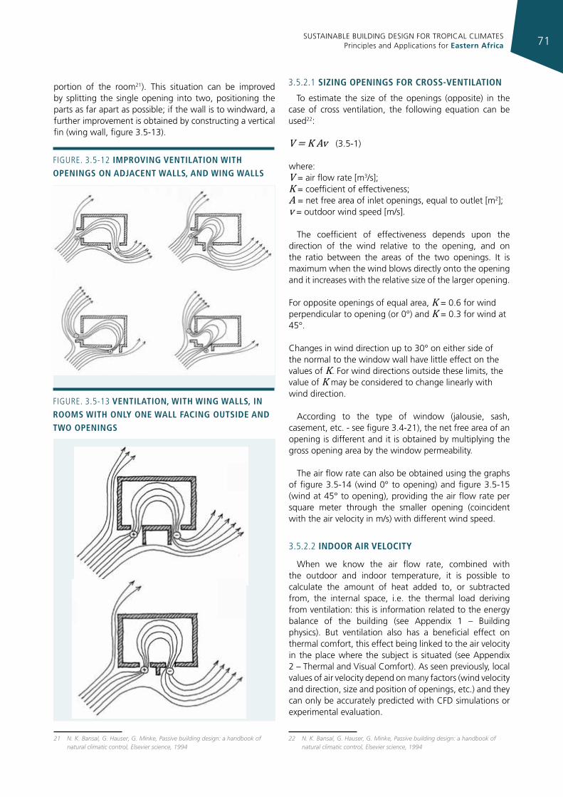
SUSTAINABLE BUILDING DESIGN FOR TROPICAL CLIMATES Principles and Applications for Eastern Africa 71
portion of the room21). This situation can be improved by splitting the single opening into two, positioning the parts as far apart as possible; if the wall is to windward, a further improvement is obtained by constructing a vertical fin (wing wall, figure 3.5-13).
21 N. K. Bansal, G. Hauser, G. Minke, Passive building design: a handbook of natural climatic control, Elsevier science, 1994
3.5.2.1 sIzIng openIngs for cross-ventIlatIon
To estimate the size of the openings (opposite) in the case of cross ventilation, the following equation can be used22:
V = K Av (3.5-1)
where: V = air flow rate [m3/s]; K = coefficient of effectiveness; A = net free area of inlet openings, equal to outlet [m2]; v = outdoor wind speed [m/s].
The coefficient of effectiveness depends upon the direction of the wind relative to the opening, and on the ratio between the areas of the two openings. It is maximum when the wind blows directly onto the opening and it increases with the relative size of the larger opening.
For opposite openings of equal area, K = 0.6 for wind perpendicular to opening (or 0°) and K = 0.3 for wind at 45°.
Changes in wind direction up to 30° on either side of the normal to the window wall have little effect on the values of K. For wind directions outside these limits, the value of K may be considered to change linearly with wind direction.
According to the type of window (jalousie, sash, casement, etc. - see figure 3.4-21), the net free area of an opening is different and it is obtained by multiplying the gross opening area by the window permeability.
The air flow rate can also be obtained using the graphs of figure 3.5-14 (wind 0° to opening) and figure 3.5-15 (wind at 45° to opening), providing the air flow rate per square meter through the smaller opening (coincident with the air velocity in m/s) with different wind speed.
3.5.2.2 Indoor aIr velocIty
When we know the air flow rate, combined with the outdoor and indoor temperature, it is possible to calculate the amount of heat added to, or subtracted from, the internal space, i.e. the thermal load deriving from ventilation: this is information related to the energy balance of the building (see Appendix 1 – Building physics). But ventilation also has a beneficial effect on thermal comfort, this effect being linked to the air velocity in the place where the subject is situated (see Appendix 2 – Thermal and Visual Comfort). As seen previously, local values of air velocity depend on many factors (wind velocity and direction, size and position of openings, etc.) and they can only be accurately predicted with CFD simulations or experimental evaluation.
22 N. K. Bansal, G. Hauser, G. Minke, Passive building design: a handbook of natural climatic control, Elsevier science, 1994
Figure. 3.5-12 ImprovIng ventIlatIon WIth openIngs on adjacent Walls, and WIng Walls
Figure. 3.5-13 ventIlatIon, WIth WIng Walls, In rooms WIth only one Wall facIng outsIde and tWo openIngs
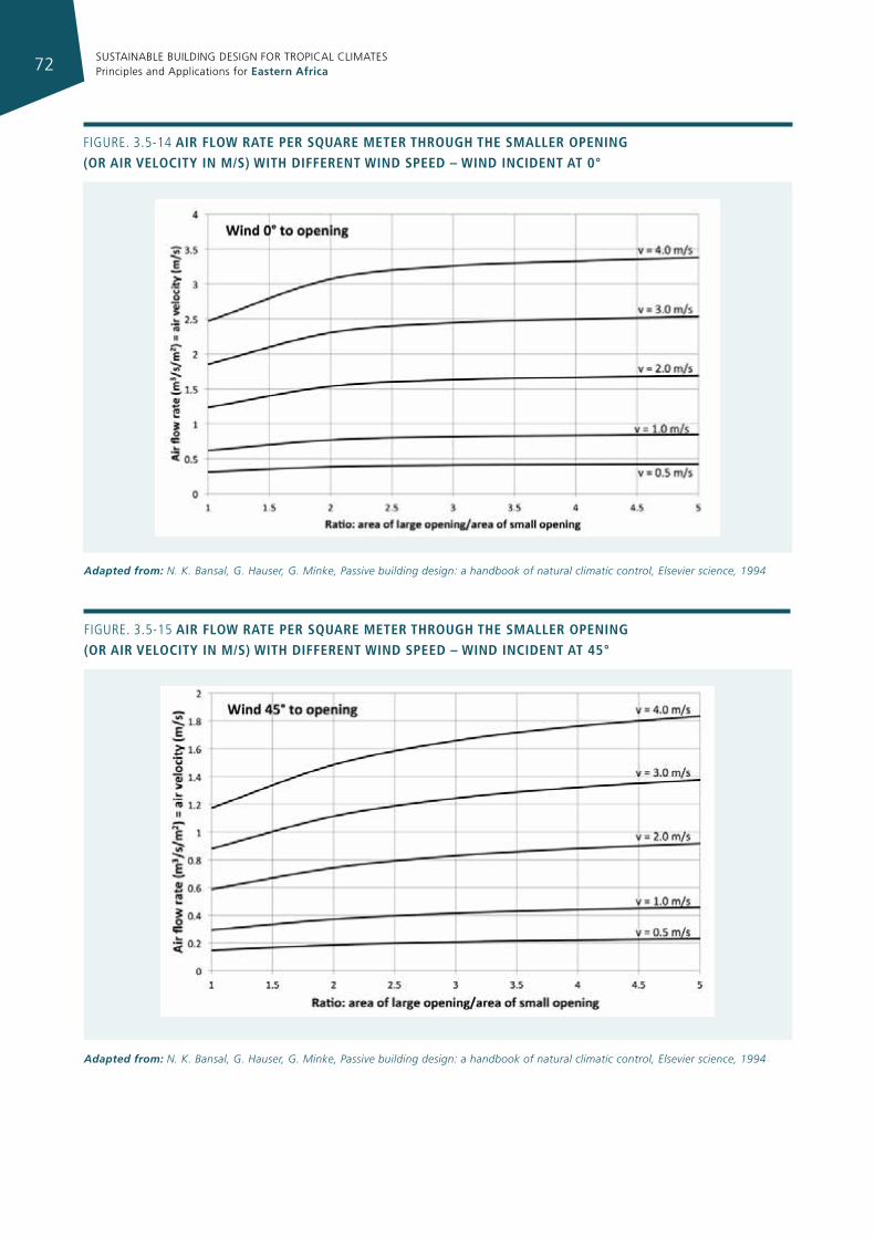
SUSTAINABLE BUILDING DESIGN FOR TROPICAL CLIMATES Principles and Applications for Eastern Africa72
Figure. 3.5-15 aIr floW rate per square meter through the smaller openIng (or aIr velocIty In m/s) WIth dIfferent WInd speed – WInd IncIdent at 45°
Adapted from: N. K. Bansal, G. Hauser, G. Minke, Passive building design: a handbook of natural climatic control, Elsevier science, 1994
Figure. 3.5-14 aIr floW rate per square meter through the smaller openIng (or aIr velocIty In m/s) WIth dIfferent WInd speed – WInd IncIdent at 0°
Adapted from: N. K. Bansal, G. Hauser, G. Minke, Passive building design: a handbook of natural climatic control, Elsevier science, 1994
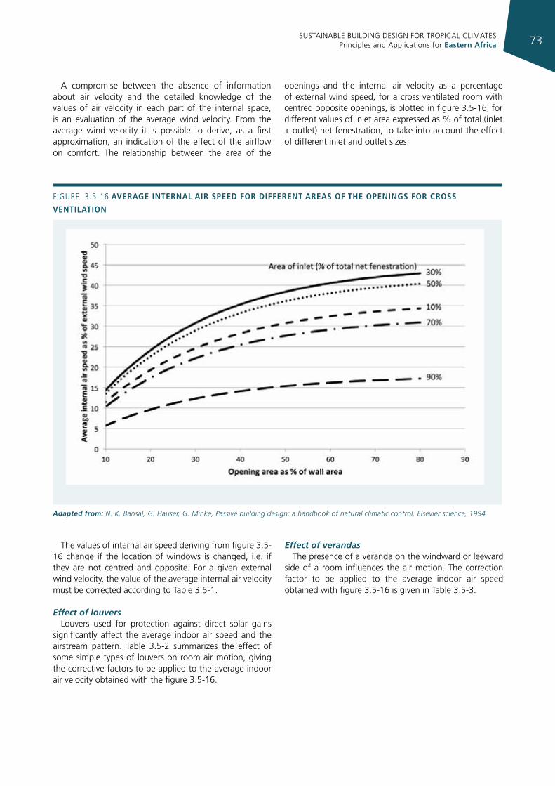
SUSTAINABLE BUILDING DESIGN FOR TROPICAL CLIMATES Principles and Applications for Eastern Africa 73
A compromise between the absence of information about air velocity and the detailed knowledge of the values of air velocity in each part of the internal space, is an evaluation of the average wind velocity. From the average wind velocity it is possible to derive, as a first approximation, an indication of the effect of the airflow on comfort. The relationship between the area of the
openings and the internal air velocity as a percentage of external wind speed, for a cross ventilated room with centred opposite openings, is plotted in figure 3.5-16, for different values of inlet area expressed as % of total (inlet + outlet) net fenestration, to take into account the effect of different inlet and outlet sizes.
Figure. 3.5-16 average Internal aIr speed for dIfferent areas of the openIngs for cross ventIlatIon
Adapted from: N. K. Bansal, G. Hauser, G. Minke, Passive building design: a handbook of natural climatic control, Elsevier science, 1994
The values of internal air speed deriving from figure 3.5-16 change if the location of windows is changed, i.e. if they are not centred and opposite. For a given external wind velocity, the value of the average internal air velocity must be corrected according to Table 3.5-1.
Effect of louversLouvers used for protection against direct solar gains
significantly affect the average indoor air speed and the airstream pattern. Table 3.5-2 summarizes the effect of some simple types of louvers on room air motion, giving the corrective factors to be applied to the average indoor air velocity obtained with the figure 3.5-16.
Effect of verandasThe presence of a veranda on the windward or leeward
side of a room influences the air motion. The correction factor to be applied to the average indoor air speed obtained with figure 3.5-16 is given in Table 3.5-3.
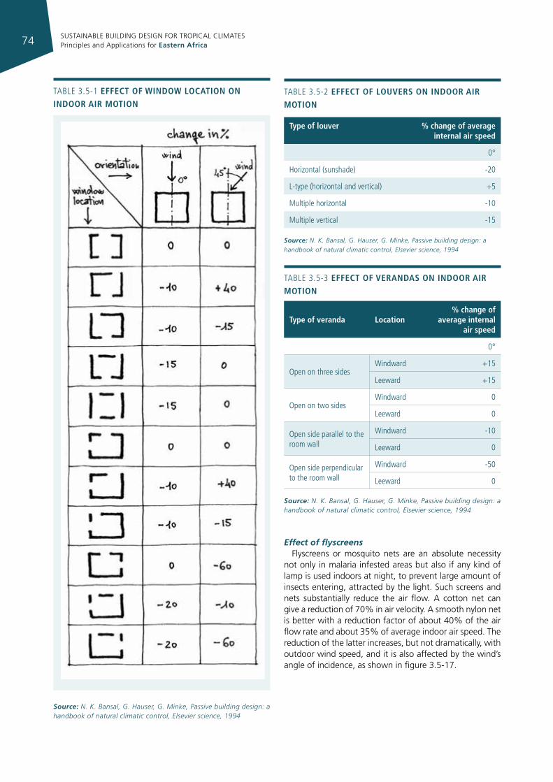
SUSTAINABLE BUILDING DESIGN FOR TROPICAL CLIMATES Principles and Applications for Eastern Africa74
Effect of flyscreensFlyscreens or mosquito nets are an absolute necessity
not only in malaria infested areas but also if any kind of lamp is used indoors at night, to prevent large amount of insects entering, attracted by the light. Such screens and nets substantially reduce the air flow. A cotton net can give a reduction of 70% in air velocity. A smooth nylon net is better with a reduction factor of about 40% of the air flow rate and about 35% of average indoor air speed. The reduction of the latter increases, but not dramatically, with outdoor wind speed, and it is also affected by the wind’s angle of incidence, as shown in figure 3.5-17.
TABLe 3.5-1 effect of WIndoW locatIon on Indoor aIr motIon
Source: N. K. Bansal, G. Hauser, G. Minke, Passive building design: a handbook of natural climatic control, Elsevier science, 1994
type of veranda location% change of
average internal air speed
0°
Open on three sidesWindward +15
Leeward +15
Open on two sidesWindward 0
Leeward 0
Open side parallel to the room wall
Windward -10
Leeward 0
Open side perpendicular to the room wall
Windward -50
Leeward 0
TABLe 3.5-3 effect of verandas on Indoor aIr motIon
Source: N. K. Bansal, G. Hauser, G. Minke, Passive building design: a handbook of natural climatic control, Elsevier science, 1994
type of louver % change of average internal air speed
0°
Horizontal (sunshade) -20
L-type (horizontal and vertical) +5
Multiple horizontal -10
Multiple vertical -15
Source: N. K. Bansal, G. Hauser, G. Minke, Passive building design: a handbook of natural climatic control, Elsevier science, 1994
TABLe 3.5-2 effect of louvers on Indoor aIr motIon
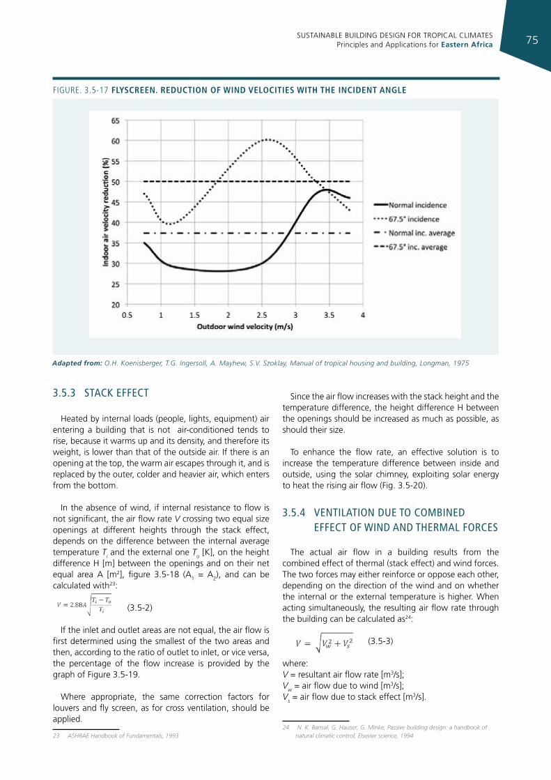
SUSTAINABLE BUILDING DESIGN FOR TROPICAL CLIMATES Principles and Applications for Eastern Africa 75
3.5.3 sTack effecT
Heated by internal loads (people, lights, equipment) air entering a building that is not air-conditioned tends to rise, because it warms up and its density, and therefore its weight, is lower than that of the outside air. If there is an opening at the top, the warm air escapes through it, and is replaced by the outer, colder and heavier air, which enters from the bottom.
In the absence of wind, if internal resistance to flow is not significant, the air flow rate V crossing two equal size openings at different heights through the stack effect, depends on the difference between the internal average temperature Ti and the external one To [K], on the height difference H [m] between the openings and on their net equal area A [m2], figure 3.5-18 (A1 = A2), and can be calculated with23:
(3.5-2)
If the inlet and outlet areas are not equal, the air flow is first determined using the smallest of the two areas and then, according to the ratio of outlet to inlet, or vice versa, the percentage of the flow increase is provided by the graph of Figure 3.5-19.
Where appropriate, the same correction factors for louvers and fly screen, as for cross ventilation, should be applied.
23 ASHRAE Handbook of Fundamentals, 1993
Since the air flow increases with the stack height and the temperature difference, the height difference H between the openings should be increased as much as possible, as should their size.
To enhance the flow rate, an effective solution is to increase the temperature difference between inside and outside, using the solar chimney, exploiting solar energy to heat the rising air flow (Fig. 3.5-20).
3.5.4 venTIlaTIon due To combIned effecT of wInd and Thermal forces
The actual air flow in a building results from the combined effect of thermal (stack effect) and wind forces. The two forces may either reinforce or oppose each other, depending on the direction of the wind and on whether the internal or the external temperature is higher. When acting simultaneously, the resulting air flow rate through the building can be calculated as24:
(3.5-3)
where: V = resultant air flow rate [m3/s]; Vw = air flow due to wind [m3/s]; Vs = air flow due to stack effect [m3/s].
24 N. K. Bansal, G. Hauser, G. Minke, Passive building design: a handbook of natural climatic control, Elsevier science, 1994
Figure. 3.5-17 flyscreen. reductIon of WInd velocItIes WIth the IncIdent angle
Adapted from: O.H. Koenisberger, T.G. Ingersoll, A. Mayhew, S.V. Szoklay, Manual of tropical housing and building, Longman, 1975
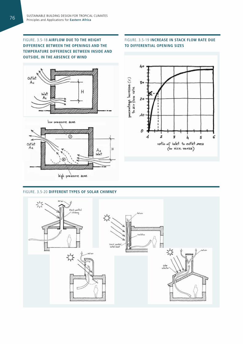
SUSTAINABLE BUILDING DESIGN FOR TROPICAL CLIMATES Principles and Applications for Eastern Africa76
Figure. 3.5-20 dIfferent types of solar chImney
Figure. 3.5-18 aIrfloW due to the heIght dIfference betWeen the openIngs and the temperature dIfference betWeen InsIde and outsIde, In the absence of WInd
Figure. 3.5-19 Increase In stack floW rate due to dIfferentIal openIng sIzes
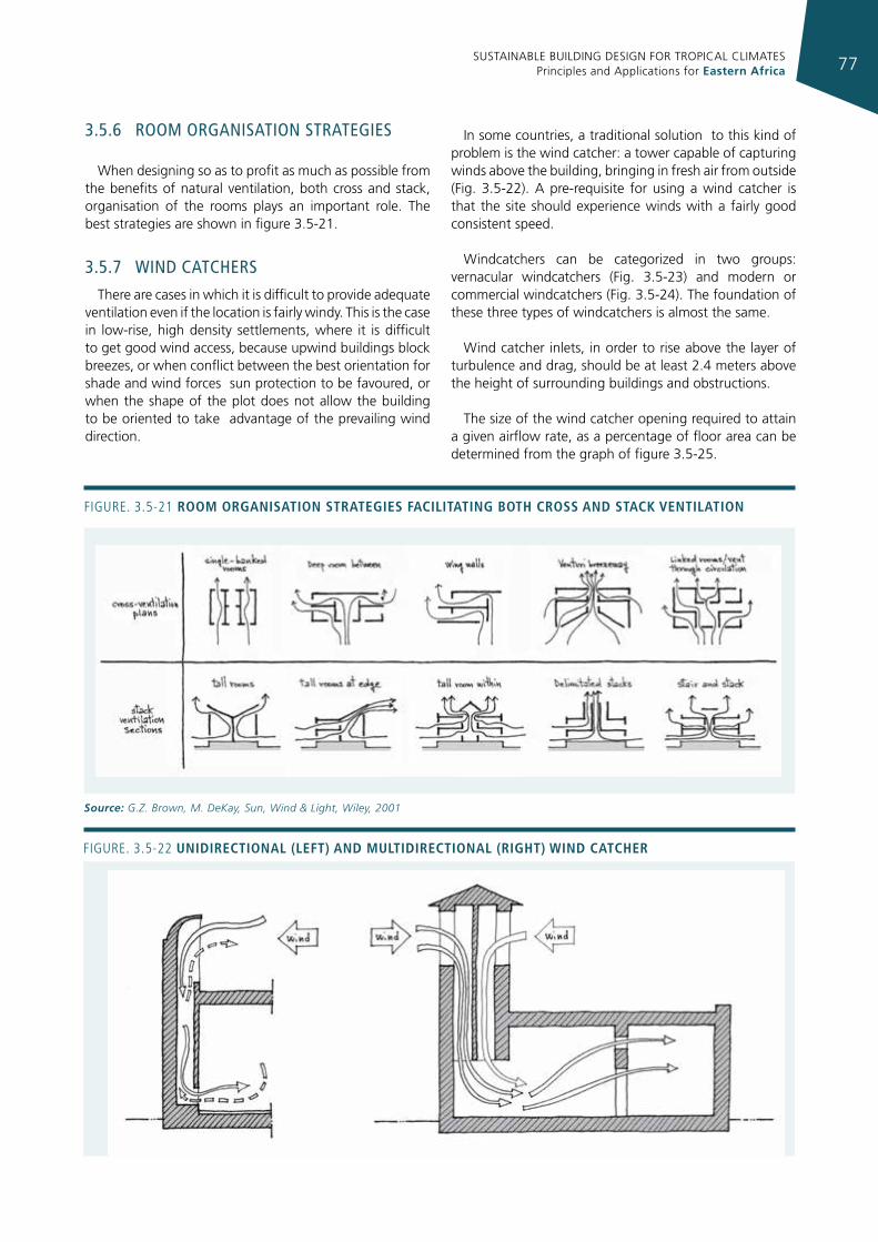
SUSTAINABLE BUILDING DESIGN FOR TROPICAL CLIMATES Principles and Applications for Eastern Africa 77
3.5.6 room organIsaTIon sTraTegIes
When designing so as to profit as much as possible from the benefits of natural ventilation, both cross and stack, organisation of the rooms plays an important role. The best strategies are shown in figure 3.5-21.
3.5.7 wInd caTchers
There are cases in which it is difficult to provide adequate ventilation even if the location is fairly windy. This is the case in low-rise, high density settlements, where it is difficult to get good wind access, because upwind buildings block breezes, or when conflict between the best orientation for shade and wind forces sun protection to be favoured, or when the shape of the plot does not allow the building to be oriented to take advantage of the prevailing wind direction.
In some countries, a traditional solution to this kind of problem is the wind catcher: a tower capable of capturing winds above the building, bringing in fresh air from outside (Fig. 3.5-22). A pre-requisite for using a wind catcher is that the site should experience winds with a fairly good consistent speed.
Windcatchers can be categorized in two groups: vernacular windcatchers (Fig. 3.5-23) and modern or commercial windcatchers (Fig. 3.5-24). The foundation of these three types of windcatchers is almost the same.
Wind catcher inlets, in order to rise above the layer of turbulence and drag, should be at least 2.4 meters above the height of surrounding buildings and obstructions.
The size of the wind catcher opening required to attain a given airflow rate, as a percentage of floor area can be determined from the graph of figure 3.5-25.
Figure. 3.5-21 room organIsatIon strategIes facIlItatIng both cross and stack ventIlatIon
Source: G.Z. Brown, M. DeKay, Sun, Wind & Light, Wiley, 2001
Figure. 3.5-22 unIdIrectIonal (left) and multIdIrectIonal (rIght) WInd catcher
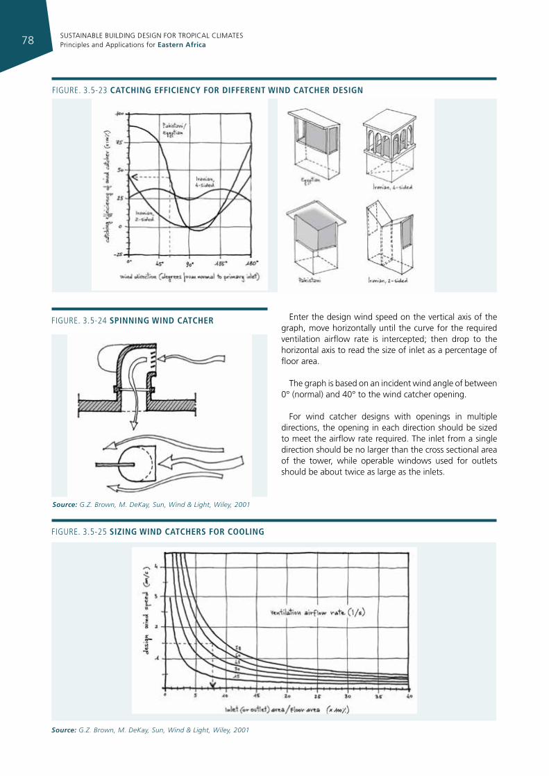
SUSTAINABLE BUILDING DESIGN FOR TROPICAL CLIMATES Principles and Applications for Eastern Africa78
Enter the design wind speed on the vertical axis of the graph, move horizontally until the curve for the required ventilation airflow rate is intercepted; then drop to the horizontal axis to read the size of inlet as a percentage of floor area.
The graph is based on an incident wind angle of between 0° (normal) and 40° to the wind catcher opening.
For wind catcher designs with openings in multiple directions, the opening in each direction should be sized to meet the airflow rate required. The inlet from a single direction should be no larger than the cross sectional area of the tower, while operable windows used for outlets should be about twice as large as the inlets.
Figure. 3.5-23 catchIng effIcIency for dIfferent WInd catcher desIgn
Figure. 3.5-25 sIzIng WInd catchers for coolIng
Source: G.Z. Brown, M. DeKay, Sun, Wind & Light, Wiley, 2001
Figure. 3.5-24 spInnIng WInd catcher
Source: G.Z. Brown, M. DeKay, Sun, Wind & Light, Wiley, 2001
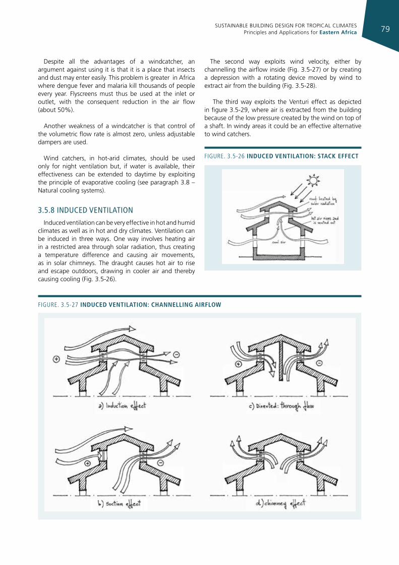
SUSTAINABLE BUILDING DESIGN FOR TROPICAL CLIMATES Principles and Applications for Eastern Africa 79
Despite all the advantages of a windcatcher, an argument against using it is that it is a place that insects and dust may enter easily. This problem is greater in Africa where dengue fever and malaria kill thousands of people every year. Flyscreens must thus be used at the inlet or outlet, with the consequent reduction in the air flow (about 50%).
Another weakness of a windcatcher is that control of the volumetric flow rate is almost zero, unless adjustable dampers are used.
Wind catchers, in hot-arid climates, should be used only for night ventilation but, if water is available, their effectiveness can be extended to daytime by exploiting the principle of evaporative cooling (see paragraph 3.8 – Natural cooling systems).
3.5.8 Induced venTIlaTIon
Induced ventilation can be very effective in hot and humid climates as well as in hot and dry climates. Ventilation can be induced in three ways. One way involves heating air in a restricted area through solar radiation, thus creating a temperature difference and causing air movements, as in solar chimneys. The draught causes hot air to rise and escape outdoors, drawing in cooler air and thereby causing cooling (Fig. 3.5-26).
The second way exploits wind velocity, either by channelling the airflow inside (Fig. 3.5-27) or by creating a depression with a rotating device moved by wind to extract air from the building (Fig. 3.5-28).
The third way exploits the Venturi effect as depicted in figure 3.5-29, where air is extracted from the building because of the low pressure created by the wind on top of a shaft. In windy areas it could be an effective alternative to wind catchers.
Figure. 3.5-26 Induced ventIlatIon: stack effect
Figure. 3.5-27 Induced ventIlatIon: channellIng aIrfloW
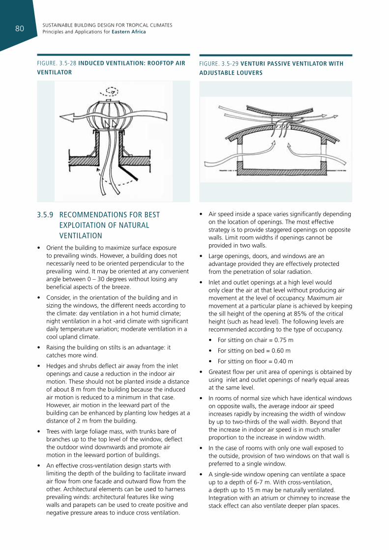
SUSTAINABLE BUILDING DESIGN FOR TROPICAL CLIMATES Principles and Applications for Eastern Africa80
3.5.9 recommendaTIons for besT exploITaTIon of naTural venTIlaTIon
• Orient the building to maximize surface exposure to prevailing winds. However, a building does not necessarily need to be oriented perpendicular to the prevailing wind. It may be oriented at any convenient angle between 0 – 30 degrees without losing any beneficial aspects of the breeze.
• Consider, in the orientation of the building and in sizing the windows, the different needs according to the climate: day ventilation in a hot humid climate; night ventilation in a hot -arid climate with significant daily temperature variation; moderate ventilation in a cool upland climate.
• Raising the building on stilts is an advantage: it catches more wind.
• Hedges and shrubs deflect air away from the inlet openings and cause a reduction in the indoor air motion. These should not be planted inside a distance of about 8 m from the building because the induced air motion is reduced to a minimum in that case. However, air motion in the leeward part of the building can be enhanced by planting low hedges at a distance of 2 m from the building.
• Trees with large foliage mass, with trunks bare of branches up to the top level of the window, deflect the outdoor wind downwards and promote air motion in the leeward portion of buildings.
• An effective cross-ventilation design starts with limiting the depth of the building to facilitate inward air flow from one facade and outward flow from the other. Architectural elements can be used to harness prevailing winds: architectural features like wing walls and parapets can be used to create positive and negative pressure areas to induce cross ventilation.
• Air speed inside a space varies significantly depending on the location of openings. The most effective strategy is to provide staggered openings on opposite walls. Limit room widths if openings cannot be provided in two walls.
• Large openings, doors, and windows are an advantage provided they are effectively protected from the penetration of solar radiation.
• Inlet and outlet openings at a high level would only clear the air at that level without producing air movement at the level of occupancy. Maximum air movement at a particular plane is achieved by keeping the sill height of the opening at 85% of the critical height (such as head level). The following levels are recommended according to the type of occupancy.
• For sitting on chair = 0.75 m
• For sitting on bed = 0.60 m
• For sitting on floor = 0.40 m
• Greatest flow per unit area of openings is obtained by using inlet and outlet openings of nearly equal areas at the same level.
• In rooms of normal size which have identical windows on opposite walls, the average indoor air speed increases rapidly by increasing the width of window by up to two-thirds of the wall width. Beyond that the increase in indoor air speed is in much smaller proportion to the increase in window width.
• In the case of rooms with only one wall exposed to the outside, provision of two windows on that wall is preferred to a single window.
• A single-side window opening can ventilate a space up to a depth of 6-7 m. With cross-ventilation, a depth up to 15 m may be naturally ventilated. Integration with an atrium or chimney to increase the stack effect can also ventilate deeper plan spaces.
Figure. 3.5-28 Induced ventIlatIon: rooftop aIr ventIlator
Figure. 3.5-29 venturI passIve ventIlator WIth adjustable louvers
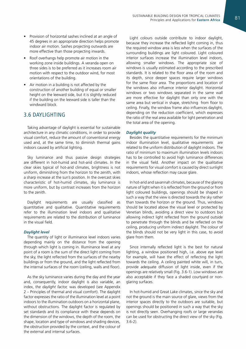
SUSTAINABLE BUILDING DESIGN FOR TROPICAL CLIMATES Principles and Applications for Eastern Africa 81
• Provision of horizontal sashes inclined at an angle of 45 degrees in an appropriate direction helps promote indoor air motion. Sashes projecting outwards are more effective than those projecting inwards.
• Roof overhangs help promote air motion in the working zone inside buildings. A veranda open on three sides is to be preferred as it increases room air motion with respect to the outdoor wind, for most orientations of the building.
• Air motion in a building is not affected by the construction of another building of equal or smaller height on the leeward side, but it is slightly reduced if the building on the leeward side is taller than the windward block.
3.6 daylIghTIng
Taking advantage of daylight is essential for sustainable architecture in any climatic conditions, in order to provide visual comfort, reduce the amount of conventional energy used and, at the same time, to diminish thermal gains indoors caused by artificial lighting.
Sky luminance and thus passive design strategies are different in hot-humid and hot-arid climates. In the clear skies typical of hot-arid climates, brightness is not uniform, diminishing from the horizon to the zenith, with a sharp increase at the sun’s position. In the overcast skies characteristic of hot-humid climates, sky luminance is more uniform, but by contrast increases from the horizon to the zenith.
Daylight requirements are usually classified as quantitative and qualitative. Quantitative requirements refer to the illumination level indoors and qualitative requirements are related to the distribution of luminance in the visual field.
Daylight level The quantity of light or illuminance level indoors varies
depending mainly on the distance from the opening through which light is coming in. Illuminance level at any point of a room is the sum of the direct light coming from the sky, the light reflected from the surfaces of the nearby buildings or from the ground, and the light reflected from the internal surfaces of the room (ceiling, walls and floor).
As the sky luminance varies during the day and the year and, consequently, indoor daylight is also variable, an index, the daylight factor, was developed (see Appendix 2 – Principles of thermal and visual comfort). The daylight factor expresses the ratio of the illumination level at a point indoors to the illumination outdoors on a horizontal plane, without obstructions. The daylight factor is regulated by set standards and its compliance with these depends on the dimension of the windows, the depth of the room, the shape, location and type of windows and shading devices, the obstruction provided by the context, and the colour of the external and internal surfaces.
Light colours outside contribute to indoor daylight, because they increase the reflected light coming in, thus the required window area is less when the surfaces of the surrounding buildings are light coloured. Light coloured interior surfaces increase the illumination level indoors, allowing smaller windows. The appropriate size of windows is usually estimated according to the prescribed standards. It is related to the floor area of the room and its depth, since deeper spaces require larger windows for the same floor area. The proportions and location of the windows also influence interior daylight. Horizontal windows or two windows separated in the same wall are more effective for daylight than only one with the same area but vertical in shape, stretching from floor to ceiling. Finally, the window frame also influences daylight, depending on the reduction coefficient, which expresses the ratio of the real area available for light penetration and the total area of the opening.
Daylight quality Besides the quantitative requirements for the minimum
indoor illumination level, qualitative requirements are related to the uniform distribution of daylight indoors. The ratio of minimum to maximum illumination levels indoors has to be controlled to avoid high luminance differences in the visual field. Another impact on the qualitative requirements for visual comfort is caused by direct sunlight indoors, whose reflection may cause glare.
In hot-arid and savannah climates, because of the glaring nature of light when it is reflected from the ground or from light coloured buildings, openings should be shaped in such a way that the view is directed towards the sky rather than towards the horizon or the ground. Thus, windows should be located above the visual level or protected by Venetian blinds, avoiding a direct view to outdoors but allowing indirect light reflected from the ground outside to penetrate through the blinds and be reflected on the ceiling, producing uniform indirect daylight. The colour of the blinds should not be very light in this case, to avoid glare from them.
Since internally reflected light is the best for natural lighting, a window positioned high, i.e. above eye level for example, will have the effect of reflecting the light towards the ceiling. A ceiling painted white will, in turn, provide adequate diffusion of light inside, even if the openings are relatively small (Fig. 3.6-1). Low windows are also acceptable if they face a shaded courtyard or non-glaring surfaces.
In hot-humid and Great Lake climates, since the sky and not the ground is the main source of glare, views from the interior spaces directly to the outdoors are suitable, but openings should be positioned in such a way that the sky is not directly seen. Overhanging roofs or large verandas can be used for obstructing the direct view of the sky (Fig. 3.6-2).
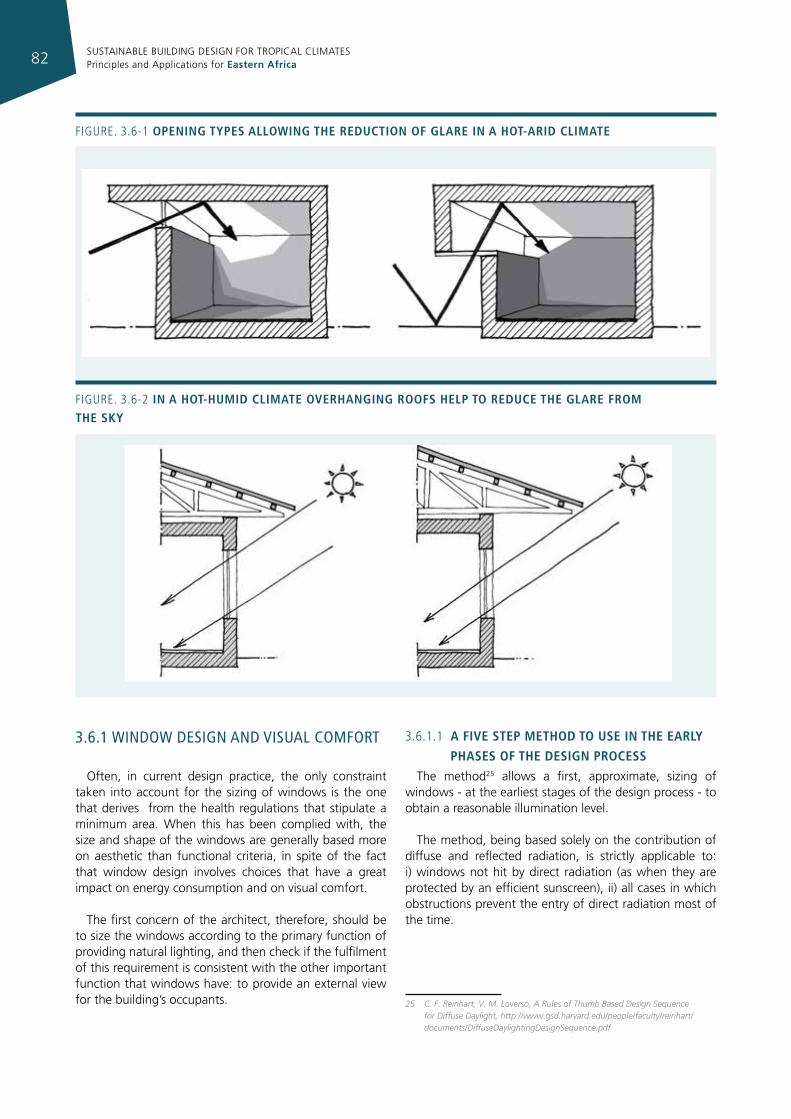
SUSTAINABLE BUILDING DESIGN FOR TROPICAL CLIMATES Principles and Applications for Eastern Africa82
3.6.1 wIndow desIgn and vIsual comforT
Often, in current design practice, the only constraint taken into account for the sizing of windows is the one that derives from the health regulations that stipulate a minimum area. When this has been complied with, the size and shape of the windows are generally based more on aesthetic than functional criteria, in spite of the fact that window design involves choices that have a great impact on energy consumption and on visual comfort.
The first concern of the architect, therefore, should be to size the windows according to the primary function of providing natural lighting, and then check if the fulfilment of this requirement is consistent with the other important function that windows have: to provide an external view for the building’s occupants.
3.6.1.1 a fIve step method to use In the early
phases of the desIgn processThe method25 allows a first, approximate, sizing of
windows - at the earliest stages of the design process - to obtain a reasonable illumination level.
The method, being based solely on the contribution of diffuse and reflected radiation, is strictly applicable to: i) windows not hit by direct radiation (as when they are protected by an efficient sunscreen), ii) all cases in which obstructions prevent the entry of direct radiation most of the time.
25 C. F. Reinhart, V. M. Loverso, A Rules of Thumb Based Design Sequence for Diffuse Daylight, http://www.gsd.harvard.edu/people/faculty/reinhart/documents/DiffuseDaylightingDesignSequence.pdf
Figure. 3.6-1 openIng types alloWIng the reductIon of glare In a hot-arId clImate
Figure. 3.6-2 In a hot-humId clImate overhangIng roofs help to reduce the glare from the sky
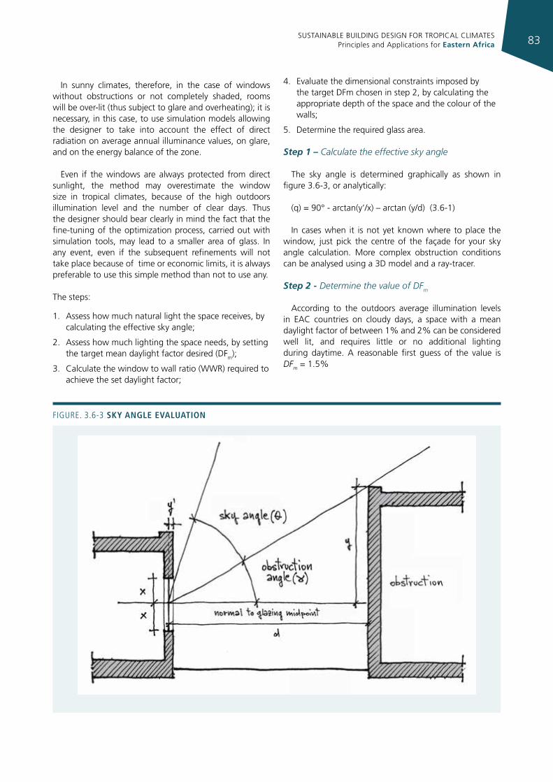
SUSTAINABLE BUILDING DESIGN FOR TROPICAL CLIMATES Principles and Applications for Eastern Africa 83
In sunny climates, therefore, in the case of windows without obstructions or not completely shaded, rooms will be over-lit (thus subject to glare and overheating); it is necessary, in this case, to use simulation models allowing the designer to take into account the effect of direct radiation on average annual illuminance values, on glare, and on the energy balance of the zone.
Even if the windows are always protected from direct sunlight, the method may overestimate the window size in tropical climates, because of the high outdoors illumination level and the number of clear days. Thus the designer should bear clearly in mind the fact that the fine-tuning of the optimization process, carried out with simulation tools, may lead to a smaller area of glass. In any event, even if the subsequent refinements will not take place because of time or economic limits, it is always preferable to use this simple method than not to use any.
The steps:
1. Assess how much natural light the space receives, by calculating the effective sky angle;
2. Assess how much lighting the space needs, by setting the target mean daylight factor desired (DFm);
3. Calculate the window to wall ratio (WWR) required to achieve the set daylight factor;
4. Evaluate the dimensional constraints imposed by the target DFm chosen in step 2, by calculating the appropriate depth of the space and the colour of the walls;
5. Determine the required glass area.
Step 1 – Calculate the effective sky angle
The sky angle is determined graphically as shown in figure 3.6-3, or analytically:
(q) = 90° - arctan(y’/x) – arctan (y/d) (3.6-1)
In cases when it is not yet known where to place the window, just pick the centre of the façade for your sky angle calculation. More complex obstruction conditions can be analysed using a 3D model and a ray-tracer.
Step 2 - Determine the value of DFm
According to the outdoors average illumination levels in EAC countries on cloudy days, a space with a mean daylight factor of between 1% and 2% can be considered well lit, and requires little or no additional lighting during daytime. A reasonable first guess of the value is DFm = 1.5%
Figure. 3.6-3 sky angle evaluatIon
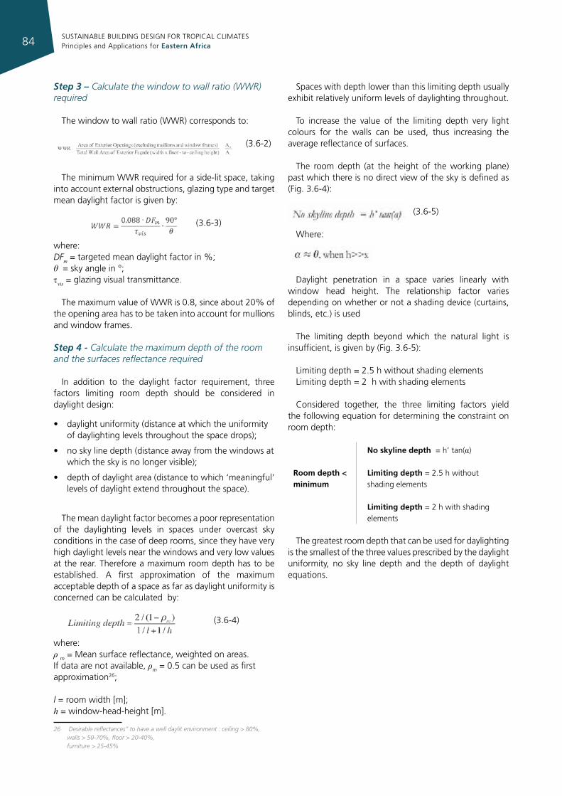
SUSTAINABLE BUILDING DESIGN FOR TROPICAL CLIMATES Principles and Applications for Eastern Africa84
Step 3 – Calculate the window to wall ratio (WWR) required
The window to wall ratio (WWR) corresponds to:
(3.6-2)
The minimum WWR required for a side-lit space, taking into account external obstructions, glazing type and target mean daylight factor is given by:
(3.6-3)
where: DFm = targeted mean daylight factor in %; θ = sky angle in °; tvis = glazing visual transmittance.
The maximum value of WWR is 0.8, since about 20% of the opening area has to be taken into account for mullions and window frames.
Step 4 - Calculate the maximum depth of the room and the surfaces reflectance required
In addition to the daylight factor requirement, three factors limiting room depth should be considered in daylight design:
• daylight uniformity (distance at which the uniformity of daylighting levels throughout the space drops);
• no sky line depth (distance away from the windows at which the sky is no longer visible);
• depth of daylight area (distance to which ‘meaningful’ levels of daylight extend throughout the space).
The mean daylight factor becomes a poor representation of the daylighting levels in spaces under overcast sky conditions in the case of deep rooms, since they have very high daylight levels near the windows and very low values at the rear. Therefore a maximum room depth has to be established. A first approximation of the maximum acceptable depth of a space as far as daylight uniformity is concerned can be calculated by:
(3.6-4)
where: ρ m = Mean surface reflectance, weighted on areas. If data are not available, ρm = 0.5 can be used as first approximation26;
l = room width [m]; h = window-head-height [m].
26 Desirable reflectances” to have a well daylit environment : ceiling > 80%, walls > 50-70%, floor > 20-40%,
furniture > 25-45%
Spaces with depth lower than this limiting depth usually exhibit relatively uniform levels of daylighting throughout.
To increase the value of the limiting depth very light colours for the walls can be used, thus increasing the average reflectance of surfaces.
The room depth (at the height of the working plane) past which there is no direct view of the sky is defined as (Fig. 3.6-4):
(3.6-5)
Where:
Daylight penetration in a space varies linearly with window head height. The relationship factor varies depending on whether or not a shading device (curtains, blinds, etc.) is used
The limiting depth beyond which the natural light is insufficient, is given by (Fig. 3.6-5):
Limiting depth = 2.5 h without shading elements Limiting depth = 2 h with shading elements
Considered together, the three limiting factors yield the following equation for determining the constraint on room depth:
Room depth < minimum
no skyline depth = h’ tan(α)
Limiting depth = 2.5 h without shading elements
Limiting depth = 2 h with shading elements
The greatest room depth that can be used for daylighting is the smallest of the three values prescribed by the daylight uniformity, no sky line depth and the depth of daylight equations.
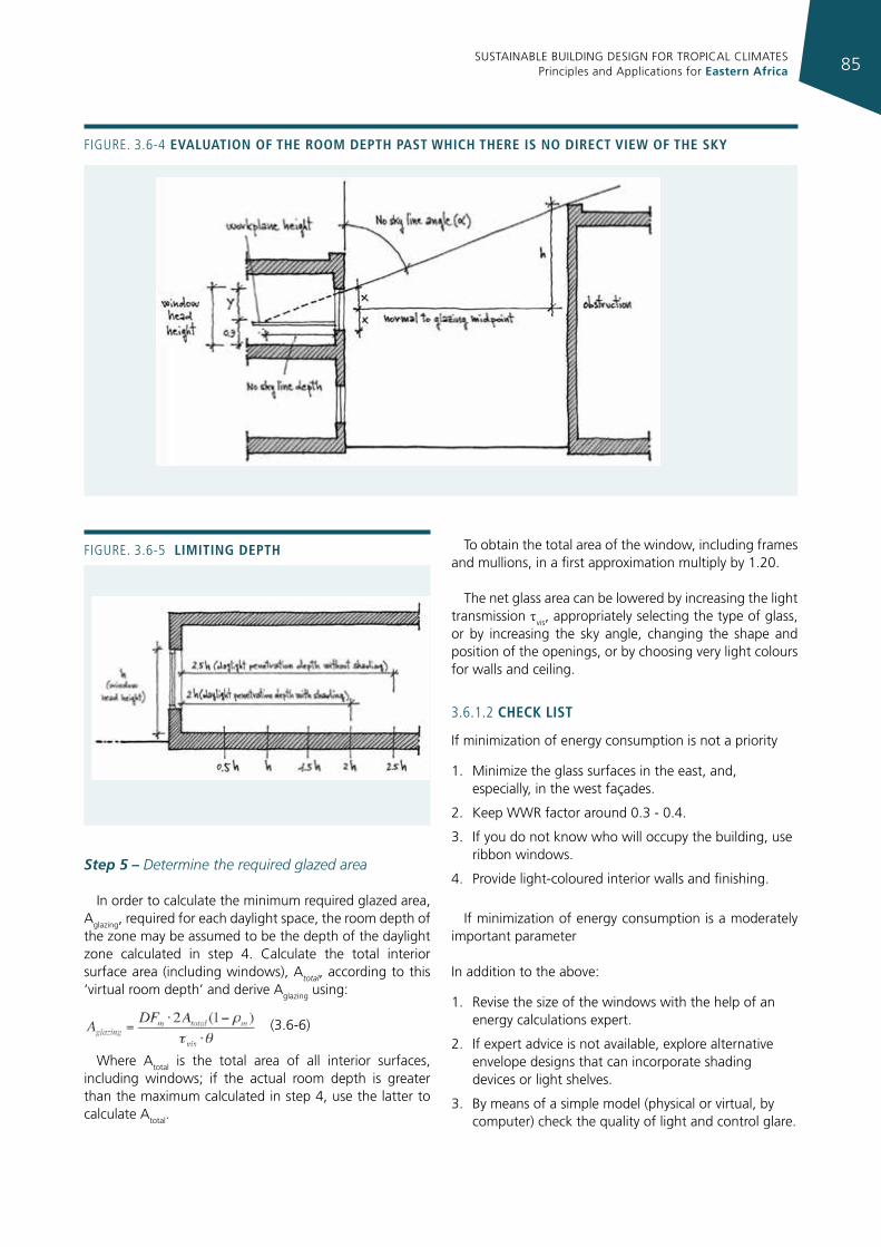
SUSTAINABLE BUILDING DESIGN FOR TROPICAL CLIMATES Principles and Applications for Eastern Africa 85
Step 5 – Determine the required glazed area
In order to calculate the minimum required glazed area, Aglazing, required for each daylight space, the room depth of the zone may be assumed to be the depth of the daylight zone calculated in step 4. Calculate the total interior surface area (including windows), Atotal, according to this ‘virtual room depth’ and derive Aglazing using:
(3.6-6)
Where Atotal is the total area of all interior surfaces, including windows; if the actual room depth is greater than the maximum calculated in step 4, use the latter to calculate Atotal.
To obtain the total area of the window, including frames and mullions, in a first approximation multiply by 1.20.
The net glass area can be lowered by increasing the light transmission tvis, appropriately selecting the type of glass, or by increasing the sky angle, changing the shape and position of the openings, or by choosing very light colours for walls and ceiling.
3.6.1.2 check lIst
If minimization of energy consumption is not a priority
1. Minimize the glass surfaces in the east, and, especially, in the west façades.
2. Keep WWR factor around 0.3 - 0.4.
3. If you do not know who will occupy the building, use ribbon windows.
4. Provide light-coloured interior walls and finishing.
If minimization of energy consumption is a moderately important parameter
In addition to the above:
1. Revise the size of the windows with the help of an energy calculations expert.
2. If expert advice is not available, explore alternative envelope designs that can incorporate shading devices or light shelves.
3. By means of a simple model (physical or virtual, by computer) check the quality of light and control glare.
Figure. 3.6-5 lImItIng depth
Figure. 3.6-4 evaluatIon of the room depth past WhIch there Is no dIrect vIeW of the sky
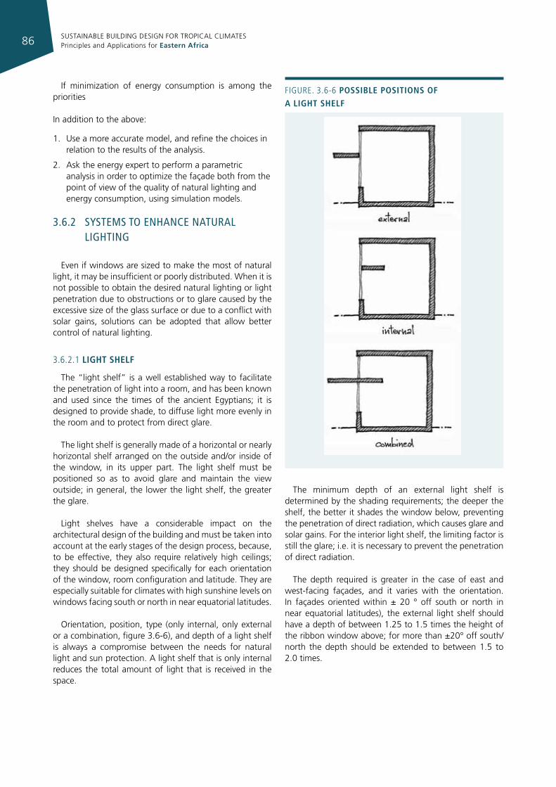
SUSTAINABLE BUILDING DESIGN FOR TROPICAL CLIMATES Principles and Applications for Eastern Africa86
If minimization of energy consumption is among the priorities
In addition to the above:
1. Use a more accurate model, and refine the choices in relation to the results of the analysis.
2. Ask the energy expert to perform a parametric analysis in order to optimize the façade both from the point of view of the quality of natural lighting and energy consumption, using simulation models.
3.6.2 sysTems To enhance naTural lIghTIng
Even if windows are sized to make the most of natural light, it may be insufficient or poorly distributed. When it is not possible to obtain the desired natural lighting or light penetration due to obstructions or to glare caused by the excessive size of the glass surface or due to a conflict with solar gains, solutions can be adopted that allow better control of natural lighting.
3.6.2.1 lIght shelf
The “light shelf” is a well established way to facilitate the penetration of light into a room, and has been known and used since the times of the ancient Egyptians; it is designed to provide shade, to diffuse light more evenly in the room and to protect from direct glare.
The light shelf is generally made of a horizontal or nearly horizontal shelf arranged on the outside and/or inside of the window, in its upper part. The light shelf must be positioned so as to avoid glare and maintain the view outside; in general, the lower the light shelf, the greater the glare.
Light shelves have a considerable impact on the architectural design of the building and must be taken into account at the early stages of the design process, because, to be effective, they also require relatively high ceilings; they should be designed specifically for each orientation of the window, room configuration and latitude. They are especially suitable for climates with high sunshine levels on windows facing south or north in near equatorial latitudes.
Orientation, position, type (only internal, only external or a combination, figure 3.6-6), and depth of a light shelf is always a compromise between the needs for natural light and sun protection. A light shelf that is only internal reduces the total amount of light that is received in the space.
The minimum depth of an external light shelf is determined by the shading requirements; the deeper the shelf, the better it shades the window below, preventing the penetration of direct radiation, which causes glare and solar gains. For the interior light shelf, the limiting factor is still the glare; i.e. it is necessary to prevent the penetration of direct radiation.
The depth required is greater in the case of east and west-facing façades, and it varies with the orientation. In façades oriented within ± 20 ° off south or north in near equatorial latitudes), the external light shelf should have a depth of between 1.25 to 1.5 times the height of the ribbon window above; for more than ±20° off south/north the depth should be extended to between 1.5 to 2.0 times.
Figure. 3.6-6 possIble posItIons of a lIght shelf
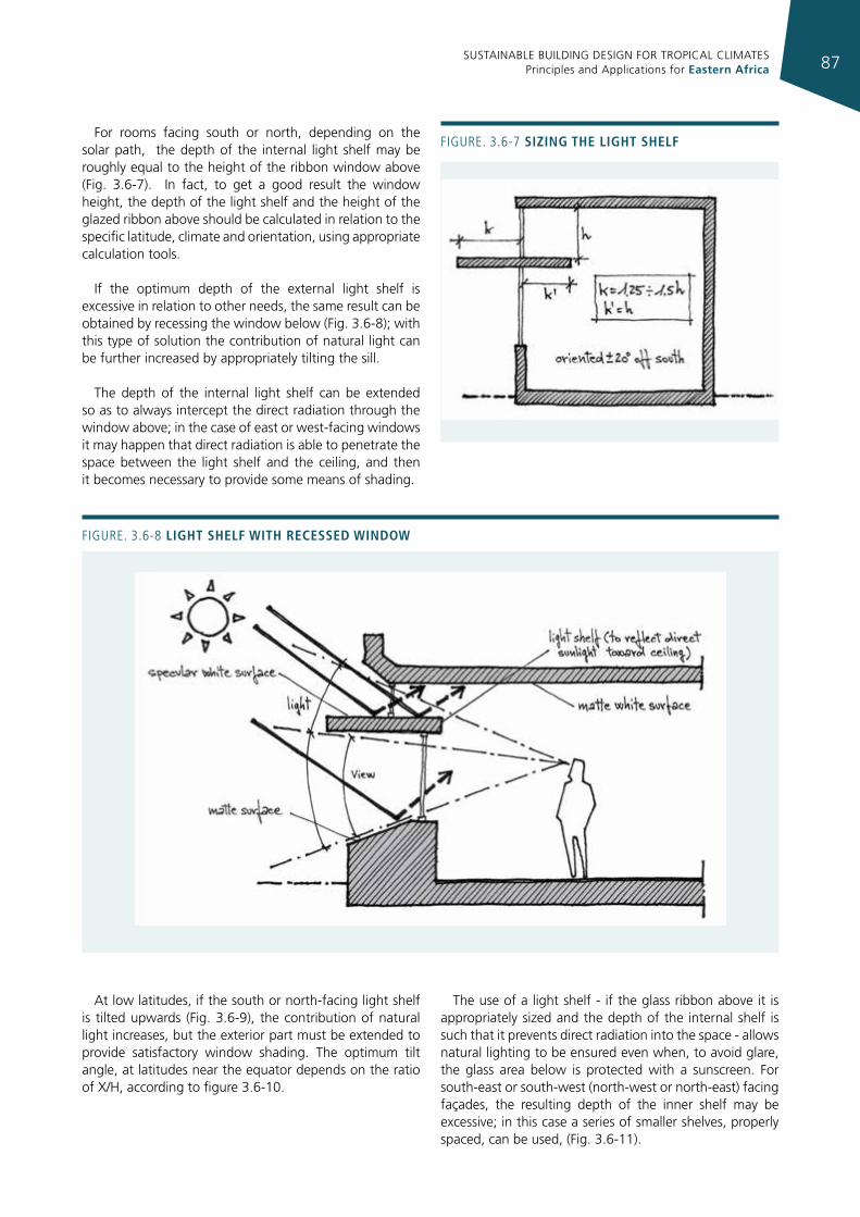
SUSTAINABLE BUILDING DESIGN FOR TROPICAL CLIMATES Principles and Applications for Eastern Africa 87
For rooms facing south or north, depending on the solar path, the depth of the internal light shelf may be roughly equal to the height of the ribbon window above (Fig. 3.6-7). In fact, to get a good result the window height, the depth of the light shelf and the height of the glazed ribbon above should be calculated in relation to the specific latitude, climate and orientation, using appropriate calculation tools.
If the optimum depth of the external light shelf is excessive in relation to other needs, the same result can be obtained by recessing the window below (Fig. 3.6-8); with this type of solution the contribution of natural light can be further increased by appropriately tilting the sill.
The depth of the internal light shelf can be extended so as to always intercept the direct radiation through the window above; in the case of east or west-facing windows it may happen that direct radiation is able to penetrate the space between the light shelf and the ceiling, and then it becomes necessary to provide some means of shading.
Figure. 3.6-8 lIght shelf WIth recessed WIndoW
Figure. 3.6-7 sIzIng the lIght shelf
At low latitudes, if the south or north-facing light shelf is tilted upwards (Fig. 3.6-9), the contribution of natural light increases, but the exterior part must be extended to provide satisfactory window shading. The optimum tilt angle, at latitudes near the equator depends on the ratio of X/H, according to figure 3.6-10.
The use of a light shelf - if the glass ribbon above it is appropriately sized and the depth of the internal shelf is such that it prevents direct radiation into the space - allows natural lighting to be ensured even when, to avoid glare, the glass area below is protected with a sunscreen. For south-east or south-west (north-west or north-east) facing façades, the resulting depth of the inner shelf may be excessive; in this case a series of smaller shelves, properly spaced, can be used, (Fig. 3.6-11).
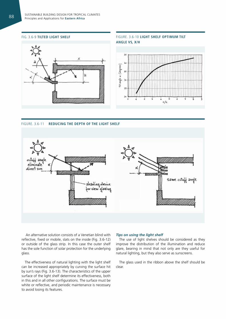
SUSTAINABLE BUILDING DESIGN FOR TROPICAL CLIMATES Principles and Applications for Eastern Africa88
An alternative solution consists of a Venetian blind with reflective, fixed or mobile, slats on the inside (Fig. 3.6-12) or outside of the glass strip. In this case the outer shelf has the sole function of solar protection for the underlying glass.
The effectiveness of natural lighting with the light shelf can be increased appropriately by curving the surface hit by sun’s rays (Fig. 3.6-13). The characteristics of the upper surface of the light shelf determine its effectiveness, both in this and in all other configurations. The surface must be white or reflective, and periodic maintenance is necessary to avoid losing its features.
Tips on using the light shelfThe use of light shelves should be considered as they
improve the distribution of the illumination and reduce glare, bearing in mind that not only are they useful for natural lighting, but they also serve as sunscreens.
The glass used in the ribbon above the shelf should be clear.
Figure. 3.6-11 reducIng the depth of the lIght shelf
Fig. 3.6-9 tIlted lIght shelf Figure. 3.6-10 lIght shelf optImum tIlt angle vs, x/h
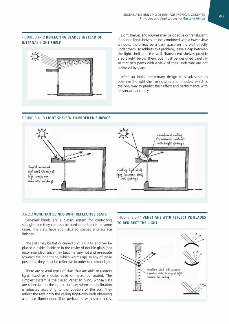
SUSTAINABLE BUILDING DESIGN FOR TROPICAL CLIMATES Principles and Applications for Eastern Africa 89
Figure. 3.6-12 reflectIng blades Instead of Internal lIght shelf
Figure. 3.6-13 lIght shelf WIth profIled surface
Light shelves and louvres may be opaque or translucent. If opaque light shelves are not combined with a lower view window, there may be a dark space on the wall directly under them. To address this problem, leave a gap between the light shelf and the wall. Translucent shelves provide a soft light below them but must be designed carefully so that occupants with a view of their underside are not bothered by glare.
After an initial preliminary design it is advisable to optimize the light shelf using simulation models, which is the only way to predict their effect and performance with reasonable accuracy.
Figure. 3.6-14 venetIans WIth reflectIve blades to redIrect the lIght
3.6.2.2 venetIan blInds WIth reflectIve slats
Venetian blinds are a classic system for controlling sunlight, but they can also be used to redirect it. In some cases, the slats have sophisticated shapes and surface finishes.
The slats may be flat or curved (Fig. 3.6-14), and can be placed outside, inside or in the cavity of double glass (not recommended, since they become very hot and re-radiate towards the inner pane, which warms up). In any of these positions, they must be reflective in order to redirect light.
There are several types of slats that are able to redirect light: fixed or mobile, solid or micro perforated. The simplest system is the classic Venetian blind, whose slats are reflective on the upper surface; when the inclination is adjusted according to the position of the sun, they reflect the rays onto the ceiling (light-coloured) obtaining a diffuse illumination. Slats perforated with small holes,
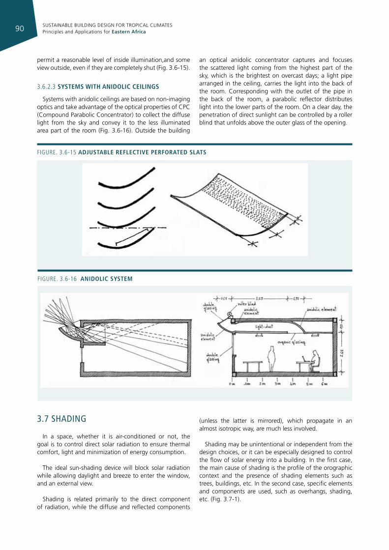
SUSTAINABLE BUILDING DESIGN FOR TROPICAL CLIMATES Principles and Applications for Eastern Africa90
permit a reasonable level of inside illumination,and some view outside, even if they are completely shut (Fig. 3.6-15).
3.6.2.3 systems WIth anIdolIc ceIlIngs
Systems with anidolic ceilings are based on non-imaging optics and take advantage of the optical properties of CPC (Compound Parabolic Concentrator) to collect the diffuse light from the sky and convey it to the less illuminated area part of the room (Fig. 3.6-16). Outside the building
an optical anidolic concentrator captures and focuses the scattered light coming from the highest part of the sky, which is the brightest on overcast days; a light pipe arranged in the ceiling, carries the light into the back of the room. Corresponding with the outlet of the pipe in the back of the room, a parabolic reflector distributes light into the lower parts of the room. On a clear day, the penetration of direct sunlight can be controlled by a roller blind that unfolds above the outer glass of the opening.
Figure. 3.6-15 adjustable reflectIve perforated slats
Figure. 3.6-16 anIdolIc system
3.7 shadIng
In a space, whether it is air-conditioned or not, the goal is to control direct solar radiation to ensure thermal comfort, light and minimization of energy consumption.
The ideal sun-shading device will block solar radiation while allowing daylight and breeze to enter the window, and an external view.
Shading is related primarily to the direct component of radiation, while the diffuse and reflected components
(unless the latter is mirrored), which propagate in an almost isotropic way, are much less involved.
Shading may be unintentional or independent from the design choices, or it can be especially designed to control the flow of solar energy into a building. In the first case, the main cause of shading is the profile of the orographic context and the presence of shading elements such as trees, buildings, etc. In the second case, specific elements and components are used, such as overhangs, shading, etc. (Fig. 3.7-1).
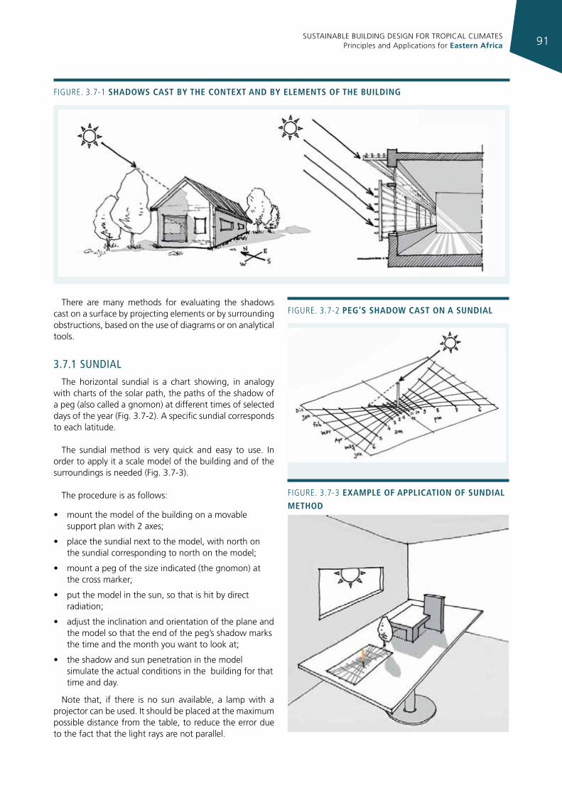
SUSTAINABLE BUILDING DESIGN FOR TROPICAL CLIMATES Principles and Applications for Eastern Africa 91
Figure. 3.7-1 shadoWs cast by the context and by elements of the buIldIng
There are many methods for evaluating the shadows cast on a surface by projecting elements or by surrounding obstructions, based on the use of diagrams or on analytical tools.
3.7.1 sundIal
The horizontal sundial is a chart showing, in analogy with charts of the solar path, the paths of the shadow of a peg (also called a gnomon) at different times of selected days of the year (Fig. 3.7-2). A specific sundial corresponds to each latitude.
The sundial method is very quick and easy to use. In order to apply it a scale model of the building and of the surroundings is needed (Fig. 3.7-3).
The procedure is as follows:
• mount the model of the building on a movable support plan with 2 axes;
• place the sundial next to the model, with north on the sundial corresponding to north on the model;
• mount a peg of the size indicated (the gnomon) at the cross marker;
• put the model in the sun, so that is hit by direct radiation;
• adjust the inclination and orientation of the plane and the model so that the end of the peg’s shadow marks the time and the month you want to look at;
• the shadow and sun penetration in the model simulate the actual conditions in the building for that time and day.
Note that, if there is no sun available, a lamp with a projector can be used. It should be placed at the maximum possible distance from the table, to reduce the error due to the fact that the light rays are not parallel.
Figure. 3.7-2 peg’s shadoW cast on a sundIal
Figure. 3.7-3 example of applIcatIon of sundIal method
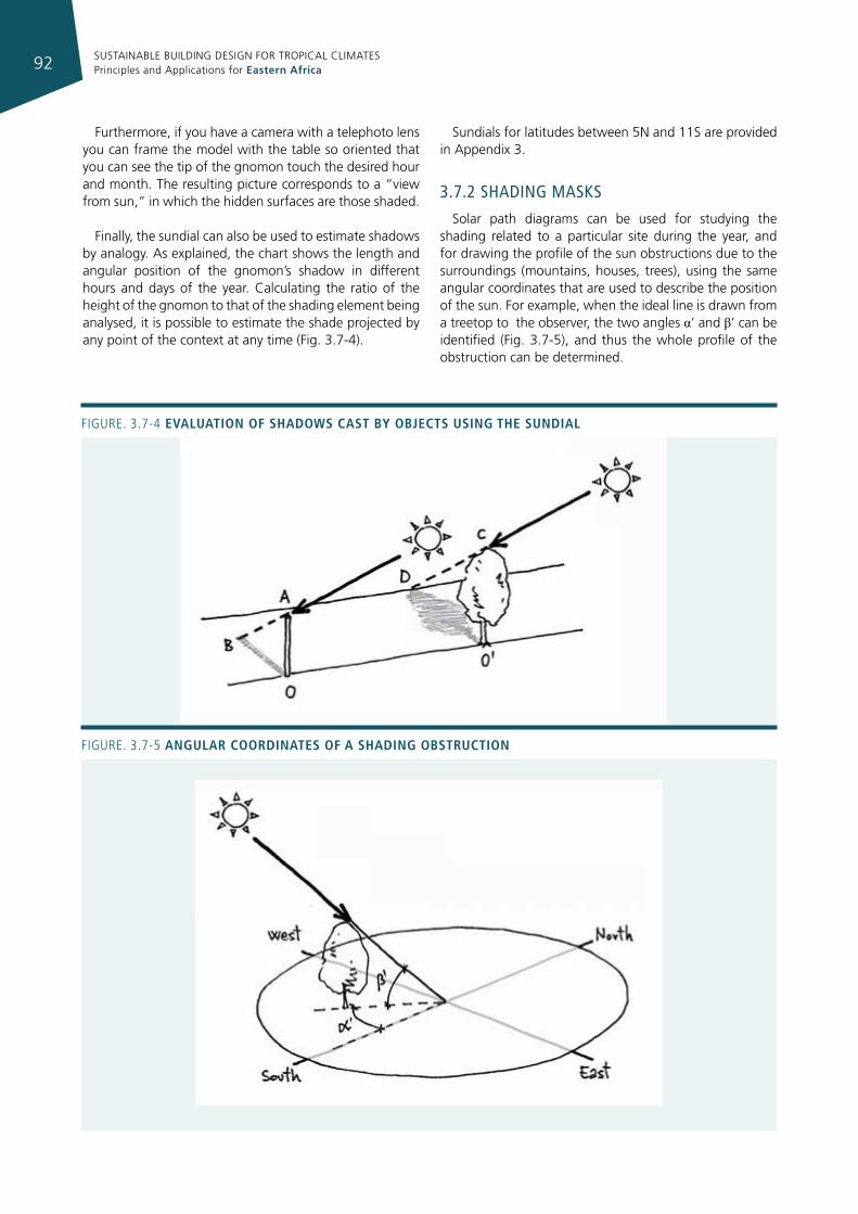
SUSTAINABLE BUILDING DESIGN FOR TROPICAL CLIMATES Principles and Applications for Eastern Africa92
Figure. 3.7-4 evaluatIon of shadoWs cast by objects usIng the sundIal
Figure. 3.7-5 angular coordInates of a shadIng obstructIon
Furthermore, if you have a camera with a telephoto lens you can frame the model with the table so oriented that you can see the tip of the gnomon touch the desired hour and month. The resulting picture corresponds to a “view from sun,” in which the hidden surfaces are those shaded.
Finally, the sundial can also be used to estimate shadows by analogy. As explained, the chart shows the length and angular position of the gnomon’s shadow in different hours and days of the year. Calculating the ratio of the height of the gnomon to that of the shading element being analysed, it is possible to estimate the shade projected by any point of the context at any time (Fig. 3.7-4).
Sundials for latitudes between 5N and 11S are provided in Appendix 3.
3.7.2 shadIng masks
Solar path diagrams can be used for studying the shading related to a particular site during the year, and for drawing the profile of the sun obstructions due to the surroundings (mountains, houses, trees), using the same angular coordinates that are used to describe the position of the sun. For example, when the ideal line is drawn from a treetop to the observer, the two angles α’ and β’ can be identified (Fig. 3.7-5), and thus the whole profile of the obstruction can be determined.
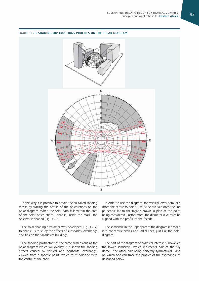
SUSTAINABLE BUILDING DESIGN FOR TROPICAL CLIMATES Principles and Applications for Eastern Africa 93
In this way it is possible to obtain the so-called shading masks by tracing the profile of the obstructions on the polar diagram. When the solar path falls within the area of the solar obstructions , that is, inside the mask, the observer is shaded (Fig. 3.7-6).
The solar shading protractor was developed (Fig. 3.7-7) to enable us to study the effects of sunshades, overhangs and fins on the façades of buildings.
The shading protractor has the same dimensions as the polar diagram which will overlay it. It shows the shading effects caused by vertical and horizontal overhangs, viewed from a specific point, which must coincide with the centre of the chart.
In order to use the diagram, the vertical lower semi-axis (from the centre to point B) must be overlaid onto the line perpendicular to the façade drawn in plan at the point being considered. Furthermore, the diameter A-A’ must be aligned with the profile of the façade.
The semicircle in the upper part of the diagram is divided into concentric circles and radial lines, just like the polar diagram.
The part of the diagram of practical interest is, however, the lower semicircle, which represents half of the sky dome - the other half being perfectly symmetrical - and on which one can trace the profiles of the overhangs, as described below.
Figure. 3.7-6 shadIng obstructIons profIles on the polar dIagram
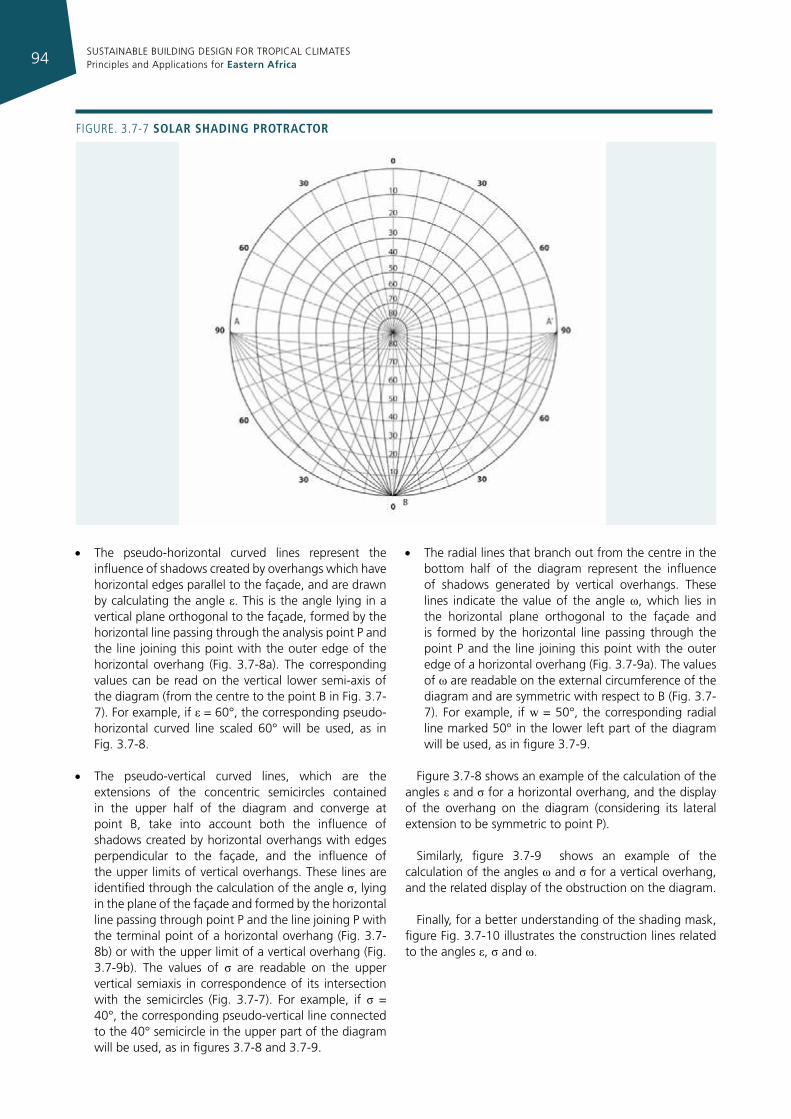
SUSTAINABLE BUILDING DESIGN FOR TROPICAL CLIMATES Principles and Applications for Eastern Africa94
Figure. 3.7-7 solar shadIng protractor
• The pseudo-horizontal curved lines represent the influence of shadows created by overhangs which have horizontal edges parallel to the façade, and are drawn by calculating the angle ε. This is the angle lying in a vertical plane orthogonal to the façade, formed by the horizontal line passing through the analysis point P and the line joining this point with the outer edge of the horizontal overhang (Fig. 3.7-8a). The corresponding values can be read on the vertical lower semi-axis of the diagram (from the centre to the point B in Fig. 3.7-7). For example, if ε = 60°, the corresponding pseudo-horizontal curved line scaled 60° will be used, as in Fig. 3.7-8.
• The pseudo-vertical curved lines, which are the extensions of the concentric semicircles contained in the upper half of the diagram and converge at point B, take into account both the influence of shadows created by horizontal overhangs with edges perpendicular to the façade, and the influence of the upper limits of vertical overhangs. These lines are identified through the calculation of the angle σ, lying in the plane of the façade and formed by the horizontal line passing through point P and the line joining P with the terminal point of a horizontal overhang (Fig. 3.7-8b) or with the upper limit of a vertical overhang (Fig. 3.7-9b). The values of σ are readable on the upper vertical semiaxis in correspondence of its intersection with the semicircles (Fig. 3.7-7). For example, if σ = 40°, the corresponding pseudo-vertical line connected to the 40° semicircle in the upper part of the diagram will be used, as in figures 3.7-8 and 3.7-9.
• The radial lines that branch out from the centre in the bottom half of the diagram represent the influence of shadows generated by vertical overhangs. These lines indicate the value of the angle ω, which lies in the horizontal plane orthogonal to the façade and is formed by the horizontal line passing through the point P and the line joining this point with the outer edge of a horizontal overhang (Fig. 3.7-9a). The values of ω are readable on the external circumference of the diagram and are symmetric with respect to B (Fig. 3.7-7). For example, if w = 50°, the corresponding radial line marked 50° in the lower left part of the diagram will be used, as in figure 3.7-9.
Figure 3.7-8 shows an example of the calculation of the angles ε and σ for a horizontal overhang, and the display of the overhang on the diagram (considering its lateral extension to be symmetric to point P).
Similarly, figure 3.7-9 shows an example of the calculation of the angles ω and σ for a vertical overhang, and the related display of the obstruction on the diagram.
Finally, for a better understanding of the shading mask, figure Fig. 3.7-10 illustrates the construction lines related to the angles ε, σ and ω.
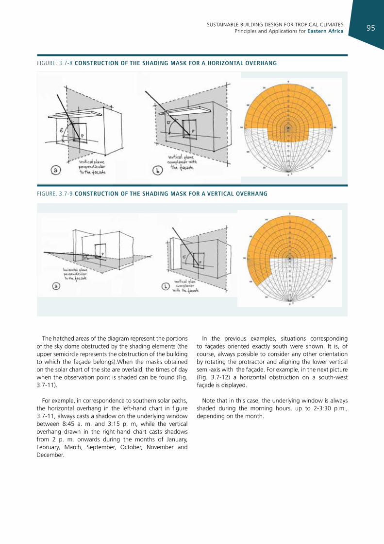
SUSTAINABLE BUILDING DESIGN FOR TROPICAL CLIMATES Principles and Applications for Eastern Africa 95
The hatched areas of the diagram represent the portions of the sky dome obstructed by the shading elements (the upper semicircle represents the obstruction of the building to which the façade belongs).When the masks obtained on the solar chart of the site are overlaid, the times of day when the observation point is shaded can be found (Fig. 3.7-11).
For example, in correspondence to southern solar paths, the horizontal overhang in the left-hand chart in figure 3.7-11, always casts a shadow on the underlying window between 8:45 a. m. and 3:15 p. m, while the vertical overhang drawn in the right-hand chart casts shadows from 2 p. m. onwards during the months of January, February, March, September, October, November and December.
In the previous examples, situations corresponding to façades oriented exactly south were shown. It is, of course, always possible to consider any other orientation by rotating the protractor and aligning the lower vertical semi-axis with the façade. For example, in the next picture (Fig. 3.7-12) a horizontal obstruction on a south-west façade is displayed.
Note that in this case, the underlying window is always shaded during the morning hours, up to 2-3:30 p.m., depending on the month.
Figure. 3.7-8 constructIon of the shadIng mask for a horIzontal overhang
Figure. 3.7-9 constructIon of the shadIng mask for a vertIcal overhang
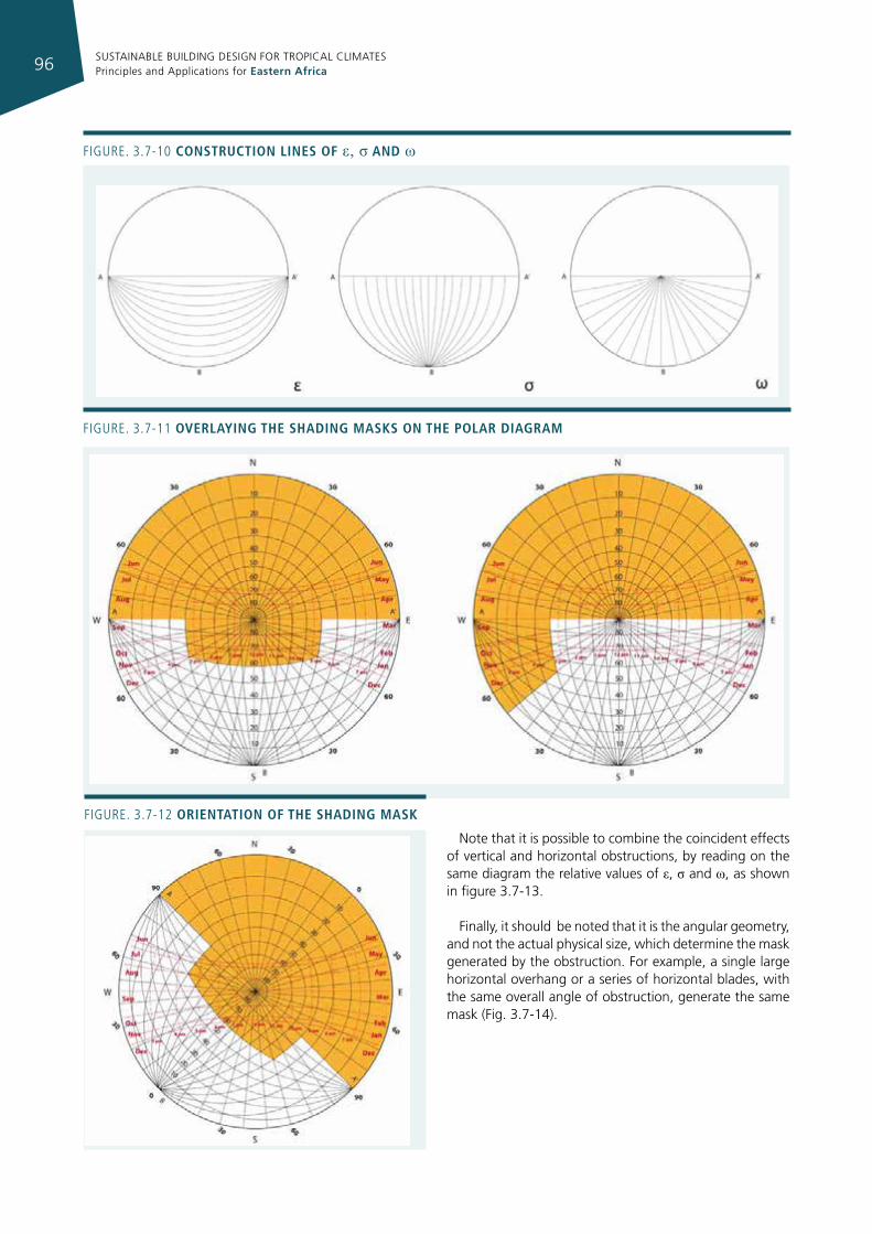
SUSTAINABLE BUILDING DESIGN FOR TROPICAL CLIMATES Principles and Applications for Eastern Africa96
Note that it is possible to combine the coincident effects of vertical and horizontal obstructions, by reading on the same diagram the relative values of ε, σ and ω, as shown in figure 3.7-13.
Finally, it should be noted that it is the angular geometry, and not the actual physical size, which determine the mask generated by the obstruction. For example, a single large horizontal overhang or a series of horizontal blades, with the same overall angle of obstruction, generate the same mask (Fig. 3.7-14).
Figure. 3.7-10 constructIon lInes of ε, σ and ω
Figure. 3.7-11 overlayIng the shadIng masks on the polar dIagram
Figure. 3.7-12 orIentatIon of the shadIng mask
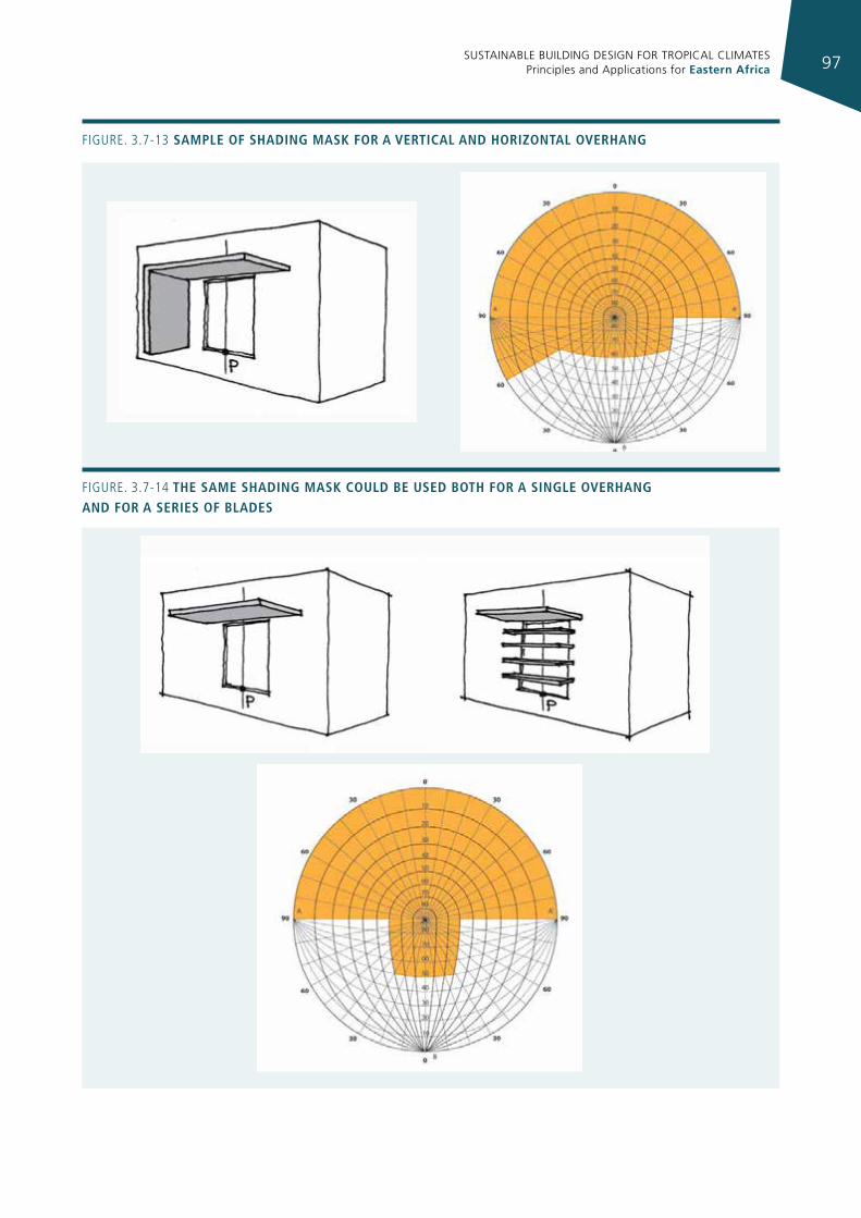
SUSTAINABLE BUILDING DESIGN FOR TROPICAL CLIMATES Principles and Applications for Eastern Africa 97
Figure. 3.7-13 sample of shadIng mask for a vertIcal and horIzontal overhang
Figure. 3.7-14 the same shadIng mask could be used both for a sIngle overhang and for a serIes of blades
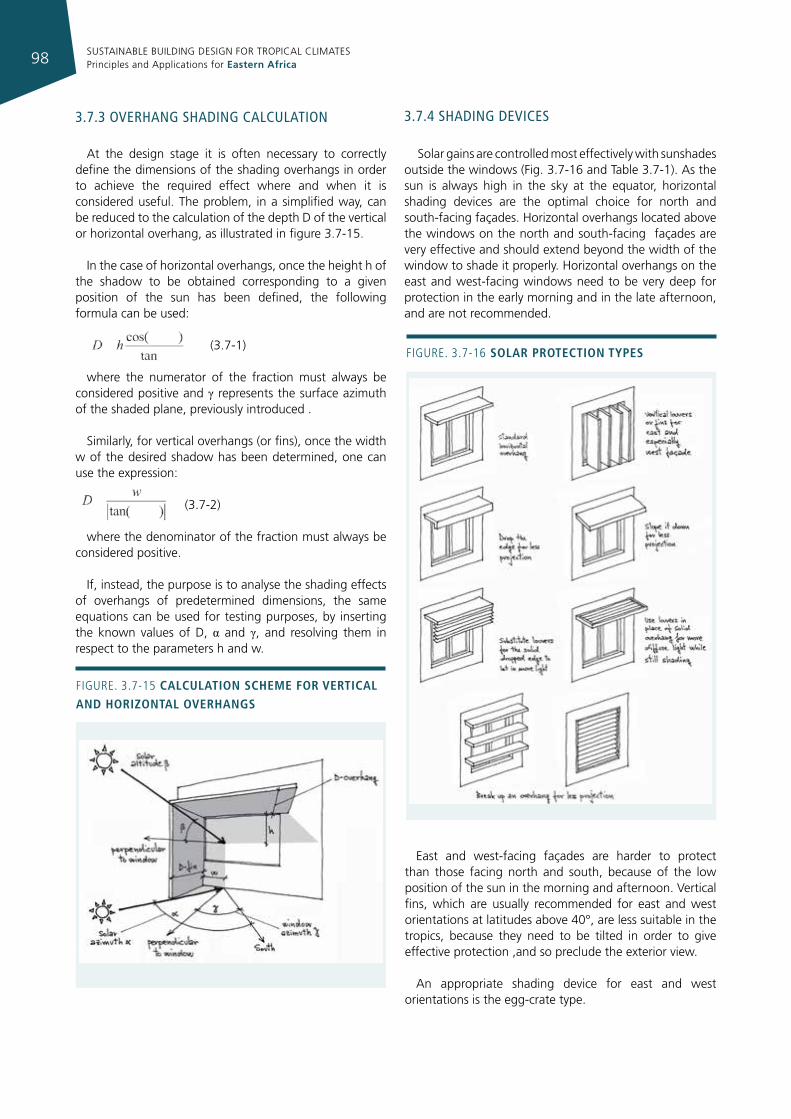
SUSTAINABLE BUILDING DESIGN FOR TROPICAL CLIMATES Principles and Applications for Eastern Africa98
3.7.4 shadIng devIces
Solar gains are controlled most effectively with sunshades outside the windows (Fig. 3.7-16 and Table 3.7-1). As the sun is always high in the sky at the equator, horizontal shading devices are the optimal choice for north and south-facing façades. Horizontal overhangs located above the windows on the north and south-facing façades are very effective and should extend beyond the width of the window to shade it properly. Horizontal overhangs on the east and west-facing windows need to be very deep for protection in the early morning and in the late afternoon, and are not recommended.
East and west-facing façades are harder to protect than those facing north and south, because of the low position of the sun in the morning and afternoon. Vertical fins, which are usually recommended for east and west orientations at latitudes above 40°, are less suitable in the tropics, because they need to be tilted in order to give effective protection ,and so preclude the exterior view.
An appropriate shading device for east and west orientations is the egg-crate type.
3.7.3 overhang shadIng calculaTIon
At the design stage it is often necessary to correctly define the dimensions of the shading overhangs in order to achieve the required effect where and when it is considered useful. The problem, in a simplified way, can be reduced to the calculation of the depth D of the vertical or horizontal overhang, as illustrated in figure 3.7-15.
In the case of horizontal overhangs, once the height h of the shadow to be obtained corresponding to a given position of the sun has been defined, the following formula can be used:
(3.7-1)
where the numerator of the fraction must always be considered positive and γ represents the surface azimuth of the shaded plane, previously introduced .
Similarly, for vertical overhangs (or fins), once the width w of the desired shadow has been determined, one can use the expression:
(3.7-2)
where the denominator of the fraction must always be considered positive.
If, instead, the purpose is to analyse the shading effects of overhangs of predetermined dimensions, the same equations can be used for testing purposes, by inserting the known values of D, α and γ, and resolving them in respect to the parameters h and w.
Figure. 3.7-15 calculatIon scheme for vertIcal and horIzontal overhangs
Figure. 3.7-16 solar protectIon types
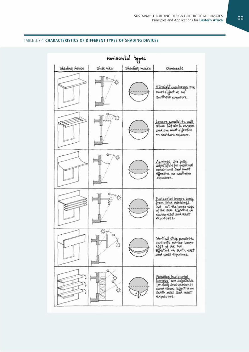
SUSTAINABLE BUILDING DESIGN FOR TROPICAL CLIMATES Principles and Applications for Eastern Africa 99
TABLe 3.7-1 characterIstIcs of dIfferent types of shadIng devIces
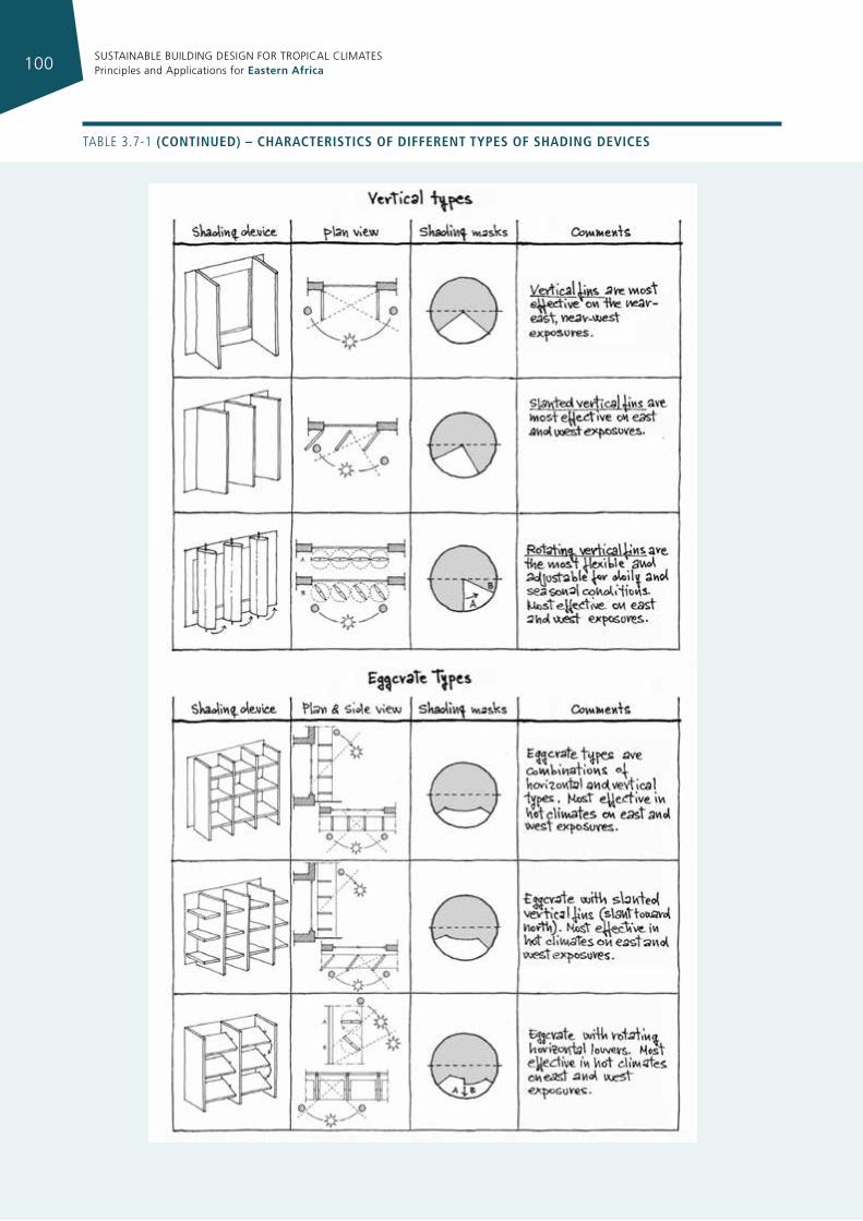
SUSTAINABLE BUILDING DESIGN FOR TROPICAL CLIMATES Principles and Applications for Eastern Africa100
TABLe 3.7-1 (contInued) – characterIstIcs of dIfferent types of shadIng devIces
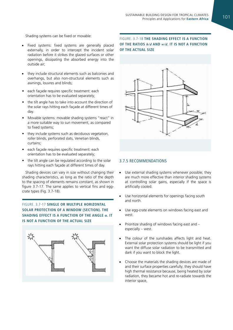
SUSTAINABLE BUILDING DESIGN FOR TROPICAL CLIMATES Principles and Applications for Eastern Africa 101
Shading systems can be fixed or movable:
• Fixed systems: fixed systems are generally placed externally, in order to intercept the incident solar radiation before it strikes the glazed surfaces or other openings, dissipating the absorbed energy into the outside air;
• they include structural elements such as balconies and overhangs, but also non-structural elements such as awnings, louvres and blinds;
• each façade requires specific treatment: each orientation has to be evaluated separately;
• the tilt angle has to take into account the direction of the solar rays hitting each façade at different times of day.
• Movable systems: movable shading systems “react” in a more suitable way to sun movement, as compared to fixed systems;
• they include systems such as deciduous vegetation, roller blinds, perforated slats, Venetian blinds, curtains;
• each façade requires specific treatment: each orientation has to be evaluated separately;
• the tilt angle can be regulated according to the solar rays hitting each façade at different times of day.
Shading devices can vary in size without changing their shading characteristics, as long as the ratio of the depth to the spacing of elements remains constant, as shown in figure 3.7-17. The same applies to vertical fins and egg-crate types (Fig. 3.7-18).
3.7.5 recommendaTIons
• Use external shading systems whenever possible; they are much more effective than interior shading systems at controlling solar gains, especially if the space is artificially cooled.
• Use horizontal elements for openings facing south and north.
• Use egg-crate elements on windows facing east and west.
• Prioritize shading of windows facing east and – especially – west.
• The colour of the sunshades affects light and heat. External solar protection systems should be light if you want the diffuse solar radiation to be transmitted and dark if you want to block the light.
• Choose the materials the shading devices are made of and their surface properties carefully; they should have high thermal resistance because, being heated by solar radiation, they became hot and re-radiate towards the interior space,
Figure. 3.7-17 sIngle or multIple horIzontal solar protectIon of a WIndoW (sectIon). the shadIng effect Is a functIon of the angle α. It Is not a functIon of the actual sIze
Figure. 3.7-18 the shadIng effect Is a functIon of the ratIos h/d and w/d. It Is not a functIon of the actual sIze
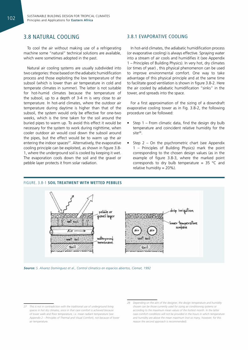
SUSTAINABLE BUILDING DESIGN FOR TROPICAL CLIMATES Principles and Applications for Eastern Africa102
3.8 naTural coolIng
To cool the air without making use of a refrigerating machine some “natural” technical solutions are available, which were sometimes adopted in the past.
Natural air cooling systems are usually subdivided into two categories: those based on the adiabatic humidification process and those exploiting the low temperature of the subsoil (which is lower than air temperature in cold and temperate climates in summer). The latter is not suitable for hot-humid climates because the temperature of the subsoil, up to a depth of 3-4 m is very close to air temperature. In hot-arid climates, where the outdoor air temperature during daytime is higher than that of the subsoil, the system would only be effective for one-two weeks, which is the time taken for the soil around the buried pipes to warm up. To avoid this effect it would be necessary for the system to work during nighttime, when cooler outdoor air would cool down the subsoil around the pipes, but the effect would be to warm up the air entering the indoor spaces27. Alternatively, the evaporative cooling principle can be exploited, as shown in figure 3.8-1, where the underground soil is cooled by keeping it wet. The evaporation cools down the soil and the gravel or pebble layer protects it from solar radiation.
27 This is not in contradiction with the traditional use of underground living spaces in hot dry climates, since in that case comfort is achieved because of lower walls and floor temperature, i.e. mean radiant temperature (see Appendix 2 – Principles of Thermal and Visual Comfort), not because of lower air temperature.
3.8.1 evaporaTIve coolIng
In hot-arid climates, the adiabatic humidification process (or evaporative cooling) is always effective. Spraying water into a stream of air cools and humidifies it (see Appendix 1 – Principles of Building Physics). In very hot, dry climates (or times of year) , this physical phenomenon can be used to improve environmental comfort. One way to take advantage of this physical principle and at the same time to facilitate good ventilation is shown in figure 3.8-2. Here the air cooled by adiabatic humidification “sinks” in the tower, and spreads into the space.
For a first approximation of the sizing of a downdraft evaporative cooling tower as in Fig. 3.8-2, the following procedure can be followed:
• Step 1 – From climatic data, find the design dry bulb temperature and coincident relative humidity for the site28.
• Step 2 – On the psychrometric chart (see Appendix 1 – Principles of Building Physics) mark the point corresponding to the chosen design values (as in the example of figure 3.8-3, where the marked point corresponds to dry bulb temperature = 35 °C and relative humidity = 20%).
28 Depending on the aim of the designer, the design temperature and humidity chosen can be those currently used for sizing air conditioning systems or according to the maximum mean values of the hottest month. In the latter case comfort conditions will not be provided in the hours in which temperature and humidity are above the mean maximum (not so many, however; for this reason the second approach is recommended).
Figure. 3.8-1 soIl treatment WIth Wetted pebbles
Source: S. Alvarez Dominguez et al., Control climatico en espacios abiertos, Ciemat, 1992
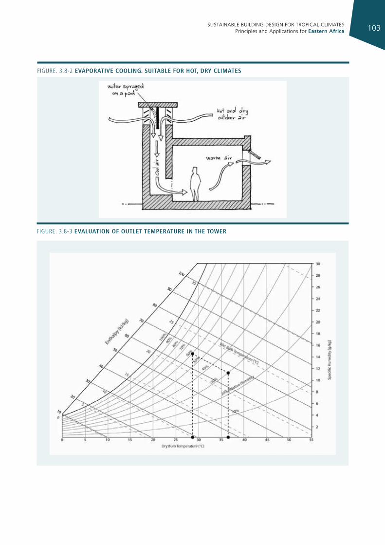
SUSTAINABLE BUILDING DESIGN FOR TROPICAL CLIMATES Principles and Applications for Eastern Africa 103
Figure. 3.8-3 evaluatIon of outlet temperature In the toWer
Figure. 3.8-2 evaporatIve coolIng. suItable for hot, dry clImates
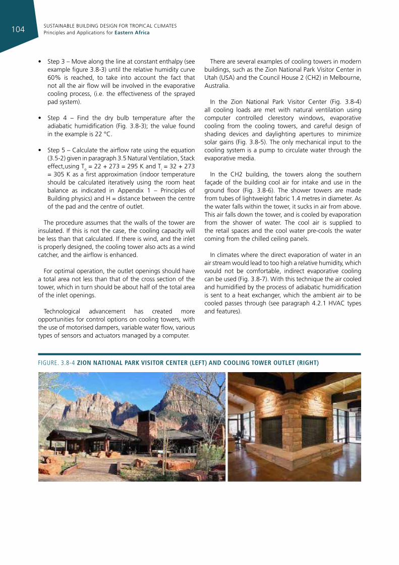
SUSTAINABLE BUILDING DESIGN FOR TROPICAL CLIMATES Principles and Applications for Eastern Africa104
• Step 3 – Move along the line at constant enthalpy (see example figure 3.8-3) until the relative humidity curve 60% is reached, to take into account the fact that not all the air flow will be involved in the evaporative cooling process, (i.e. the effectiveness of the sprayed pad system).
• Step 4 – Find the dry bulb temperature after the adiabatic humidification (Fig. 3.8-3); the value found in the example is 22 °C.
• Step 5 – Calculate the airflow rate using the equation (3.5-2) given in paragraph 3.5 Natural Ventilation, Stack effect,using To = 22 + 273 = 295 K and Ti = 32 + 273 = 305 K as a first approximation (indoor temperature should be calculated iteratively using the room heat balance as indicated in Appendix 1 – Principles of Building physics) and H = distance between the centre of the pad and the centre of outlet.
The procedure assumes that the walls of the tower are insulated. If this is not the case, the cooling capacity will be less than that calculated. If there is wind, and the inlet is properly designed, the cooling tower also acts as a wind catcher, and the airflow is enhanced.
For optimal operation, the outlet openings should have a total area not less than that of the cross section of the tower, which in turn should be about half of the total area of the inlet openings.
Technological advancement has created more opportunities for control options on cooling towers, with the use of motorised dampers, variable water flow, various types of sensors and actuators managed by a computer.
There are several examples of cooling towers in modern buildings, such as the Zion National Park Visitor Center in Utah (USA) and the Council House 2 (CH2) in Melbourne, Australia.
In the Zion National Park Visitor Center (Fig. 3.8-4) all cooling loads are met with natural ventilation using computer controlled clerestory windows, evaporative cooling from the cooling towers, and careful design of shading devices and daylighting apertures to minimize solar gains (Fig. 3.8-5). The only mechanical input to the cooling system is a pump to circulate water through the evaporative media.
In the CH2 building, the towers along the southern façade of the building cool air for intake and use in the ground floor (Fig. 3.8-6). The shower towers are made from tubes of lightweight fabric 1.4 metres in diameter. As the water falls within the tower, it sucks in air from above. This air falls down the tower, and is cooled by evaporation from the shower of water. The cool air is supplied to the retail spaces and the cool water pre-cools the water coming from the chilled ceiling panels.
In climates where the direct evaporation of water in an air stream would lead to too high a relative humidity, which would not be comfortable, indirect evaporative cooling can be used (Fig. 3.8-7). With this technique the air cooled and humidified by the process of adiabatic humidification is sent to a heat exchanger, which the ambient air to be cooled passes through (see paragraph 4.2.1 HVAC types and features).
Figure. 3.8-4 zIon natIonal park vIsItor center (left) and coolIng toWer outlet (rIght)
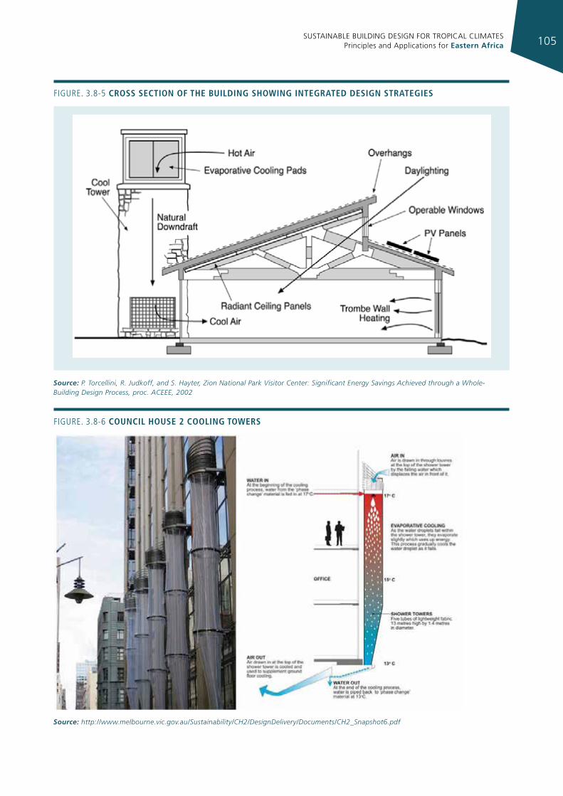
SUSTAINABLE BUILDING DESIGN FOR TROPICAL CLIMATES Principles and Applications for Eastern Africa 105
Figure. 3.8-5 cross sectIon of the buIldIng shoWIng Integrated desIgn strategIes
Source: P. Torcellini, R. Judkoff, and S. Hayter, Zion National Park Visitor Center: Significant Energy Savings Achieved through a Whole-Building Design Process, proc. ACEEE, 2002
Figure. 3.8-6 councIl house 2 coolIng toWers
Source: http://www.melbourne.vic.gov.au/Sustainability/CH2/DesignDelivery/Documents/CH2_Snapshot6.pdf
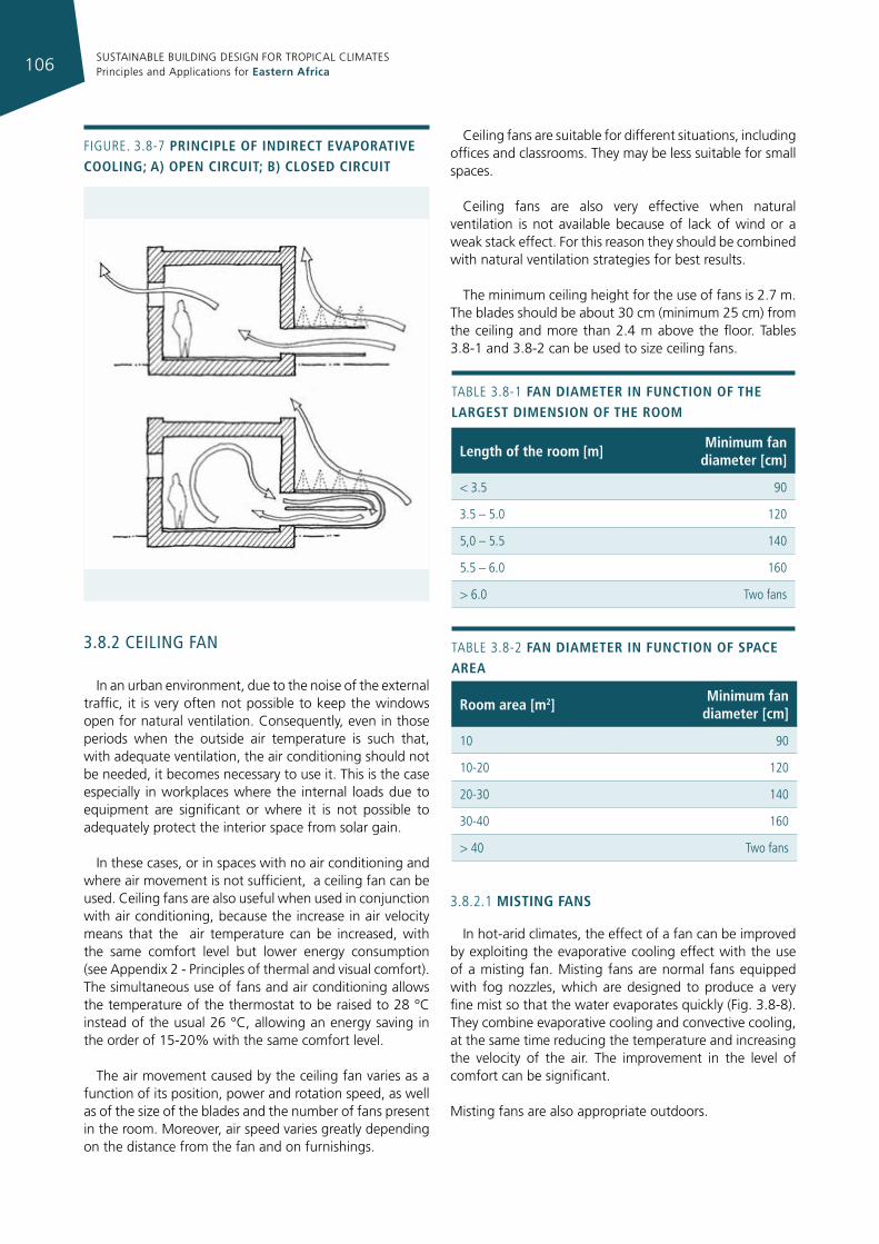
SUSTAINABLE BUILDING DESIGN FOR TROPICAL CLIMATES Principles and Applications for Eastern Africa106
3.8.2 ceIlIng fan
In an urban environment, due to the noise of the external traffic, it is very often not possible to keep the windows open for natural ventilation. Consequently, even in those periods when the outside air temperature is such that, with adequate ventilation, the air conditioning should not be needed, it becomes necessary to use it. This is the case especially in workplaces where the internal loads due to equipment are significant or where it is not possible to adequately protect the interior space from solar gain.
In these cases, or in spaces with no air conditioning and where air movement is not sufficient, a ceiling fan can be used. Ceiling fans are also useful when used in conjunction with air conditioning, because the increase in air velocity means that the air temperature can be increased, with the same comfort level but lower energy consumption (see Appendix 2 - Principles of thermal and visual comfort). The simultaneous use of fans and air conditioning allows the temperature of the thermostat to be raised to 28 °C instead of the usual 26 °C, allowing an energy saving in the order of 15-20% with the same comfort level.
The air movement caused by the ceiling fan varies as a function of its position, power and rotation speed, as well as of the size of the blades and the number of fans present in the room. Moreover, air speed varies greatly depending on the distance from the fan and on furnishings.
Ceiling fans are suitable for different situations, including offices and classrooms. They may be less suitable for small spaces.
Ceiling fans are also very effective when natural ventilation is not available because of lack of wind or a weak stack effect. For this reason they should be combined with natural ventilation strategies for best results.
The minimum ceiling height for the use of fans is 2.7 m. The blades should be about 30 cm (minimum 25 cm) from the ceiling and more than 2.4 m above the floor. Tables 3.8-1 and 3.8-2 can be used to size ceiling fans.
3.8.2.1 mIstIng fans
In hot-arid climates, the effect of a fan can be improved by exploiting the evaporative cooling effect with the use of a misting fan. Misting fans are normal fans equipped with fog nozzles, which are designed to produce a very fine mist so that the water evaporates quickly (Fig. 3.8-8). They combine evaporative cooling and convective cooling, at the same time reducing the temperature and increasing the velocity of the air. The improvement in the level of comfort can be significant.
Misting fans are also appropriate outdoors.
Figure. 3.8-7 prIncIple of IndIrect evaporatIve coolIng; a) open cIrcuIt; b) closed cIrcuIt
room area [m2]minimum fan
diameter [cm]
10 90
10-20 120
20-30 140
30-40 160
> 40 Two fans
TABLe 3.8-2 fan dIameter In functIon of space area
length of the room [m]minimum fan
diameter [cm]
< 3.5 90
3.5 – 5.0 120
5,0 – 5.5 140
5.5 – 6.0 160
> 6.0 Two fans
TABLe 3.8-1 fan dIameter In functIon of the largest dImensIon of the room
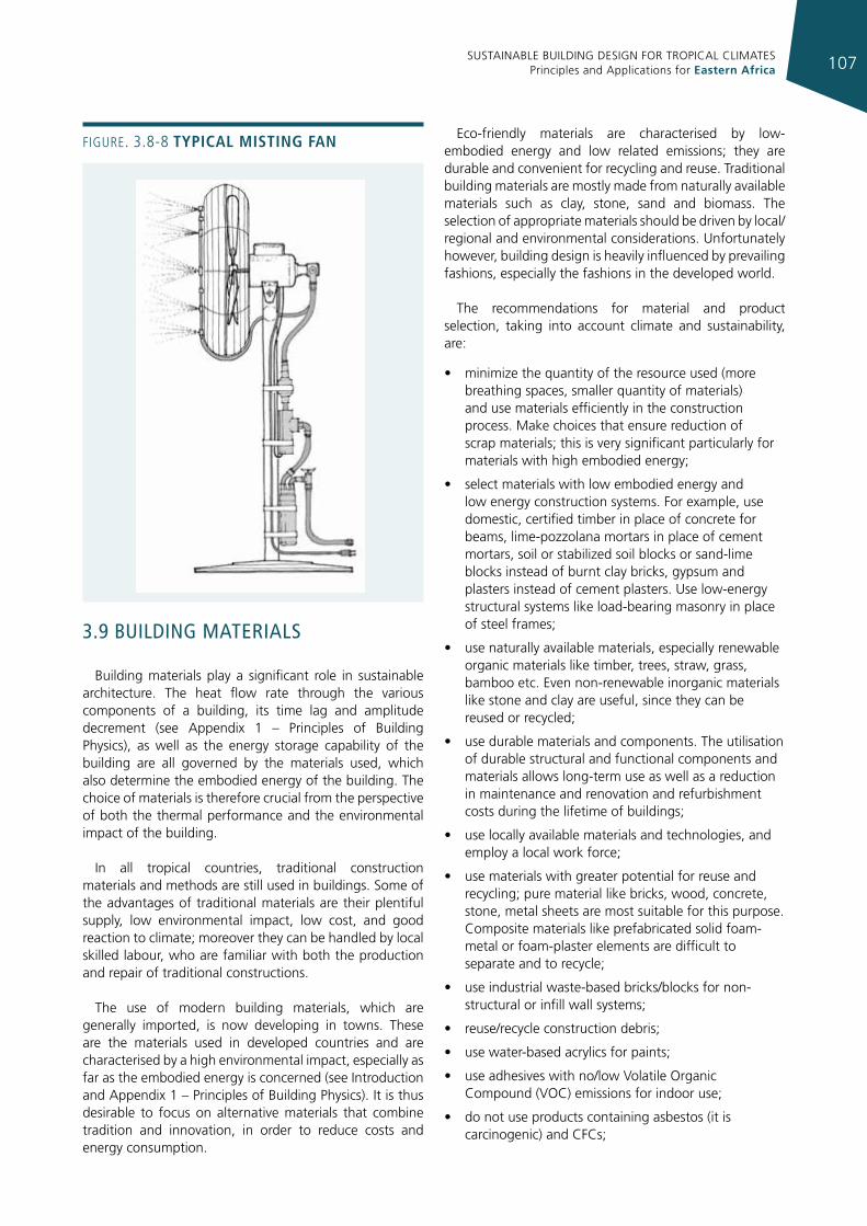
SUSTAINABLE BUILDING DESIGN FOR TROPICAL CLIMATES Principles and Applications for Eastern Africa 107
3.9 buIldIng maTerIals
Building materials play a significant role in sustainable architecture. The heat flow rate through the various components of a building, its time lag and amplitude decrement (see Appendix 1 – Principles of Building Physics), as well as the energy storage capability of the building are all governed by the materials used, which also determine the embodied energy of the building. The choice of materials is therefore crucial from the perspective of both the thermal performance and the environmental impact of the building.
In all tropical countries, traditional construction materials and methods are still used in buildings. Some of the advantages of traditional materials are their plentiful supply, low environmental impact, low cost, and good reaction to climate; moreover they can be handled by local skilled labour, who are familiar with both the production and repair of traditional constructions.
The use of modern building materials, which are generally imported, is now developing in towns. These are the materials used in developed countries and are characterised by a high environmental impact, especially as far as the embodied energy is concerned (see Introduction and Appendix 1 – Principles of Building Physics). It is thus desirable to focus on alternative materials that combine tradition and innovation, in order to reduce costs and energy consumption.
Eco-friendly materials are characterised by low-embodied energy and low related emissions; they are durable and convenient for recycling and reuse. Traditional building materials are mostly made from naturally available materials such as clay, stone, sand and biomass. The selection of appropriate materials should be driven by local/regional and environmental considerations. Unfortunately however, building design is heavily influenced by prevailing fashions, especially the fashions in the developed world.
The recommendations for material and product selection, taking into account climate and sustainability, are:
• minimize the quantity of the resource used (more breathing spaces, smaller quantity of materials) and use materials efficiently in the construction process. Make choices that ensure reduction of scrap materials; this is very significant particularly for materials with high embodied energy;
• select materials with low embodied energy and low energy construction systems. For example, use domestic, certified timber in place of concrete for beams, lime-pozzolana mortars in place of cement mortars, soil or stabilized soil blocks or sand-lime blocks instead of burnt clay bricks, gypsum and plasters instead of cement plasters. Use low-energy structural systems like load-bearing masonry in place of steel frames;
• use naturally available materials, especially renewable organic materials like timber, trees, straw, grass, bamboo etc. Even non-renewable inorganic materials like stone and clay are useful, since they can be reused or recycled;
• use durable materials and components. The utilisation of durable structural and functional components and materials allows long-term use as well as a reduction in maintenance and renovation and refurbishment costs during the lifetime of buildings;
• use locally available materials and technologies, and employ a local work force;
• use materials with greater potential for reuse and recycling; pure material like bricks, wood, concrete, stone, metal sheets are most suitable for this purpose. Composite materials like prefabricated solid foam-metal or foam-plaster elements are difficult to separate and to recycle;
• use industrial waste-based bricks/blocks for non-structural or infill wall systems;
• reuse/recycle construction debris;
• use water-based acrylics for paints;
• use adhesives with no/low Volatile Organic Compound (VOC) emissions for indoor use;
• do not use products containing asbestos (it is carcinogenic) and CFCs;
Figure. 3.8-8 typIcal mIstIng fan
SUSTAINABLE BUILDING DESIGN FOR TROPICAL CLIMATES Principles and Applications for Eastern Africa108
• minimise the use of metallic surfaces and metallic pipes, fittings, and fixtures;
• use products and materials with reduced packaging.
3.9.1 susTaInably managed maTerIals
The use of sustainably managed materials is an environmental responsibility, contributing to a sustainable habitat. The degree of sustainability of a material/component can be evaluated by means of the Life Cycle Assessment (LCA), a technique for assessing environmental impacts associated with all the stages of a product’s life, from-cradle-to-grave (i.e., from raw material extraction through processing, manufacture, distribution, use, repair and maintenance, to disposal or recycling of the materials). The LCA is a tool for measuring the environmental performance of a building material, which gives the designer a comprehensive understanding of the environmental impact and the improvement that can be offered at each stage in the life cycle of a material; it thus forms a system for comparing and selecting materials.
The guiding principle remains that all the stages in the life cycle of a material - right from raw material extraction, manufacture, and production to operation, installation and maintenance, and ultimate demolition - have potential environmental impacts.
3.9.1.1 Walls
Brick and block products made up of recycled content. Use brick and block products that have waste and
recycled contents such as fly ash29 from coal burning plants, blast furnace slag, sewage sludge, waste wood fibre, rice husk ash, etc. Concrete blocks using lime, gypsum or fly ash, or furnace slag, or waste wood fibre reduce waste and save energy. Fly ash can be used to replace about 15% to 35% of the total cementitious material. The slag content should usually be between 20% and 25%. Concrete masonry units with finished faces can provide the structure and either the interior or exterior surface of a wall, thereby reducing whole layers of additional material. Concrete blocks are also made from sintered clays, PFA (pulverized fuel ash), lime, which sinter the waste product using the residual fuel in the waste, and thus have very a low embodied energy content. Use glass blocks with recycled content.
Perforated burnt clay and cement bricks also reduce the energy requirements.
Earth blocks The production of simple earth blocks only requires
around one thousandth of the energy needed to fire bricks, and even in cases where the earth is stabilized with cement it is no more than a sixth per kg of material.
29 Fly ash is a by-product of coal in thermal power plants. It consists of organic and inorganic matter that is not fully burnt, and can be recycled for use in a variety of building materials.
Earth blocks stabilized with 5%-15% of cement are also a good choice for low cost, low-rise construction in all climates, provided that their thickness is appropriate (thick in hot- arid, thin in hot-humid, intermediate in other climates).
Stones.Native or quarried stones available within a delivery
radius of less than 100 km have a much smaller embodied energy content, negligible transport energy costs, and only need shaping.
Organic, vegetal materials. Matting of bamboo, grass, or leaves is a good material in
hot-humid zones, which has no thermal storage capacity and no airtightness, thus allows proper ventilation.
3.9.1.2 roofs
In the tropics the outer roof covering must satisfy opposing requirements. Its waterproof capability must remain unaltered in high humidity and heavy rainfall, as well as in extremely high surface temperatures combined with minimum humidity.
All roofing materials such as tiles, metal, etc., are suitable for the tropics, when appropriately used.
Earth. Good thermal insulation and emissivity, suitable in arid
climates.
Burnt clay tiles. A traditional material still very suitable today, with quite
good thermal properties. Although heavier than sheet roofs, their thermal mass is not great enough to store heat during the day and release it at night if a ventilated void is provided. They are relatively heavy, and require a strong support structure. They are permeable to air through the gaps between the tiles.
Concrete tiles. Similar properties as clay tiles but somewhat reduced
heat resistance.
Fibre concrete (FCR) and micro concrete (MCR) tiles. Similar properties but lighter than concrete tiles, hence
less heat storage capacity.
Monolithic concrete slab. Poor thermal resistance and high storage capacity. Due
to their large mass they are relatively cool during the morning, but re-radiate the daytime heat to the interior in the evening and at night.
SUSTAINABLE BUILDING DESIGN FOR TROPICAL CLIMATES Principles and Applications for Eastern Africa 109
Natural stone (flag stone, slate).Thermal performance similar to concrete tiles depending
on the thickness and the surface (brightness).
Organic, vegetal roofing materials bamboo, leaves, thatch, wooden shingles.
Climatically and environmentally suitable, but of relatively low durability. Thatch roofing is widely used in rural situations throughout East Africa. It is cost efficient and effective for sound and thermal insulation. The lifespan of an average thatch roof is 7-10 years if maintained properly.
Bituminous roofing. Problematic in the tropics, because of quick deterioration
due to the intense solar radiation combined with the dark colour.
Single skin corrugated galvanized iron sheeting (CGI).
Even though it is one of the most widely used roofing materials, it has many drawbacks: it has no significant thermal resistance; aged sheeting has no significant reflectivity, it re-radiates the received solar radiation into the building creating intolerably high indoor temperatures during the daytime. In order to preserve the reflective quality of corrugated iron sheets, and increase their life span, such roofs should be painted in a light colour. Lime wash can be used, but frequent maintenance is required. Rapid cooling at night may cause condensation in humid climates. It has a short life-span and it is noisy when it rains.
Corrugated aluminium sheetsWith their high degree of reflection, they have been a
success, but a good quality article is also fairly expensive. The high initial price is largely compensated for by low maintenance costs, which are definitely preferable to those for galvanised corrugated iron roofs, or worse non-galvanised and just painted. However, an insulating layer below the sheet is required or a ventilated cavity, for good thermal and acoustic performance.
Bituminous roofing feltGuaranteed as suitable for tropical use, roofing felt and
plastic foil are used for flat roofs, as in the temperate zones. Excessive heating of the material can be prevented simply by whitewashing it. A layer of gravel is even better because the durability of the roofing is improved and it is protected from mechanical damage.
3.9.1.3 InsulatIon materIals
Various natural and artificial materials are available and have to be selected carefully.
Glass fibre insulationAvailable as batts (blankets) that can be attached to the
underside of a roof or laid on top of a ceiling. Glass fibre insulation is produced from sand and limestone or recycled glass and typically has a formaldehyde-based binder added to it. Some manufacturers make glass fibre insulation that is free of binders or that use acrylic binders.
Cellulose insulationTypically made from recycled newsprint, and can usually
be produced locally. Since it takes relatively little energy to produce, it is usually the insulation product with the lowest embodied energy and lowest environmental impact. Cellulose is produced by either chopping newsprint into small pieces (hammer mill), shredding (disk refining) or disaggregating into fibres (fibrerization).
Moulded Expanded Polystyrene (MEPS)Commonly known as “beadboard”. Beadboard is made
from loose, unexpanded polystyrene beads containing liquid pentane and a blowing agent, which are heated to expand the beads and increase thermal resistance.
Extruded Expanded Polystyrene (XEPS)This is a closed-cell foam insulation similar to MEPS.
Polystyrene pellets are mixed with chemicals to form a liquid, and a blowing agent is injected into the mixture, to form gas bubbles. The liquid mixture is solidified through a cooling process and the gas bubbles are trapped to give it an insulating property. It has a higher compressive strength than MEPS, making it better suited for use on roofs or for wall panels.
PolyisocyanurateThis is a closed-cell foam typically produced as a foam and
used as rigid thermal insulation similar to polyurethane. All polystirene and polyisocyanurate based insulations have a more or less significant environmental impact.
3.9.1.4 sustaInable local/InnovatIve buIldIng
materIals
Stabilized compressed earth blocks (CEB)30. These blocks are made of mud stabilized with
approximately four to six per cent of cement lime and compacted with either motorized hydraulic or hand-operated machines, a process which requires no burning.
Earth building has a long history in Africa and CEB have been used in East Africa for the past 25 years.
The advantages of CEB are that they use locally found materials, shipping costs are eliminated, the blocks have a low moisture content, and the blocks are uniform thereby minimizing, if not eliminating, the use of mortar and decreasing both labour and materials costs. Construction is fast, minimal cement is used and the blocks produced are
30 Source: Architectural Design Guide EMI EAST AFRICA - http://emiea.org/documents/eMiEA_Architectural_Design_Guide.pdf
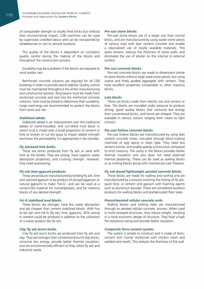
SUSTAINABLE BUILDING DESIGN FOR TROPICAL CLIMATES Principles and Applications for Eastern Africa110
of comparable strength to locally fired bricks but without their environmental impact. CEB machines can be used by supervised unskilled labour and can be transported by wheelbarrow or cart to remote locations.
The quality of the blocks is dependent on consistent quality control during the making of the blocks and throughout the construction process.
Durability may be a problem if the blocks are exposed to wind and/or rain.
Reinforced concrete columns are required for all CEB buildings in order to provide lateral stability. Quality control must be maintained throughout the entire manufacturing and construction process. Ring beams must be made from reinforced concrete and tied into the reinforced concrete columns. Soils must be tested to determine their suitability. Large overhangs are recommended to protect the blocks from wind and rain.
Stabilized adobe. Stabilized adobe is an improvement over the traditional
adobe or hand-moulded, and sun-dried mud block in which mud is mixed with a small proportion of cement or lime or broken or cut dry grass to impart added strength and lower the permeability. It is appropriate in dry climates.
Fly ash/sand lime bricks. These are bricks produced from fly ash or sand with
lime as the binder. They are strong, have superior water absorption properties, and crushing strength. However, they need autoclaving.
Fly ash-lime-gypsum products. These are products manufactured by binding fly ash, lime
and calcined gypsum (a by-product of phosphogypsum or natural gypsum) to make ‘Fal-G’, and can be used as a cement-like material for mortar/plasters, and for masonry blocks of any desired strength.
Fal-G stabilized mud blocks. These blocks are stronger, have less water absorption
and are cheaper than cement stabilized blocks. With five to ten per cent Fal-G (fly ash, lime, gypsum), 30% saving in cement could be achieved in addition to the utilization of a waste product like fly ash.
Clay fly ash burnt bricks.Clay fly ash burnt bricks are produced from fly ash and
clay. They are stronger than conventional burnt clay bricks, consume less energy, provide better thermal insulation, and are environmentally efficient as they utilize fly ash and industrial waste.
Pre-cast stone blocks. Pre-cast stone blocks are of a larger size than normal
bricks, and are manufactured by using waste stone pieces of various sizes with lean cement concrete and enable a rationalized use of locally available materials. This saves cement, reduces the thickness of stone walls, and eliminates the use of plaster on the internal or external surface.
Pre-cast concrete blocks. Pre-cast concrete blocks are made to dimensions similar
to stone blocks without large sized stone pieces, but using coarse and finely graded aggregate with cement. They have excellent properties comparable to other masonry blocks.
Lato blocks These are bricks made from lateritic soil and cement or
lime. The blocks are moulded under pressure to produce strong, good quality blocks that consume less energy than conventional bricks, and hence are cheaper. They are available in various colours ranging from cream to light crimson.
Pre-cast hollow concrete blocks. Pre-cast hollow blocks are manufactured by using lean
cement concrete mixes, extruded through block-making machines of egg laying or static type. They need less cement mortar, and enable speedy construction compared to brick masonry. The cavity in the blocks provides better thermal insulation and also does not need external/ internal plastering. These can be used as walling blocks or as roofing blocks along with inverted pre-cast T-beams.
Fly ash-based lightweight aerated concrete blocks. These blocks are made for walling and roofing and are
manufactured by a process involving the mixing of fly ash, quick lime, or cement and gypsum with foaming agents such as aluminium powder. These are considered excellent products for walling blocks and prefabricated floor slabs.
Precast/aerated cellular concrete units. Walling blocks and roofing slabs are manufactured
through an aerated cellular concrete process. When used in multi-storeyed structures, they reduce weight, resulting in a more economic design of structure. They have a high fire resistance rating and provide better insulation.
Composite ferro-cement system. The system is simple to construct and is made of ferro-
cement (rich mortar reinforced with chicken mesh and welded wire mesh). This reduces the thickness of the wall.
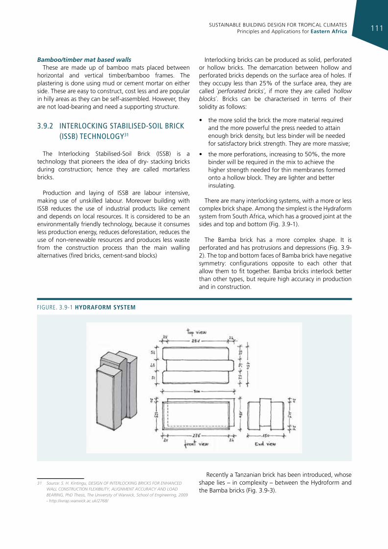
SUSTAINABLE BUILDING DESIGN FOR TROPICAL CLIMATES Principles and Applications for Eastern Africa 111
Bamboo/timber mat based walls These are made up of bamboo mats placed between
horizontal and vertical timber/bamboo frames. The plastering is done using mud or cement mortar on either side. These are easy to construct, cost less and are popular in hilly areas as they can be self-assembled. However, they are not load-bearing and need a supporting structure.
3.9.2 InTerlockIng sTabIlIsed-soIl brIck (Issb) Technology31
The Interlocking Stabilised-Soil Brick (ISSB) is a technology that pioneers the idea of dry- stacking bricks during construction; hence they are called mortarless bricks.
Production and laying of ISSB are labour intensive, making use of unskilled labour. Moreover building with ISSB reduces the use of industrial products like cement and depends on local resources. It is considered to be an environmentally friendly technology, because it consumes less production energy, reduces deforestation, reduces the use of non-renewable resources and produces less waste from the construction process than the main walling alternatives (fired bricks, cement-sand blocks)
31 Source: S. H. Kintingu, DESIGN OF INTERLOCKING BRICKS FOR ENHANCED WALL CONSTRUCTION FLEXIBILITY, ALIGNMENT ACCURACY AND LOAD BEARING, PhD Thesis, The University of Warwick, School of Engineering, 2009 - http://wrap.warwick.ac.uk/2768/
Interlocking bricks can be produced as solid, perforated or hollow bricks. The demarcation between hollow and perforated bricks depends on the surface area of holes. If they occupy less than 25% of the surface area, they are called `perforated bricks`, if more they are called `hollow blocks`. Bricks can be characterised in terms of their solidity as follows:
• the more solid the brick the more material required and the more powerful the press needed to attain enough brick density, but less binder will be needed for satisfactory brick strength. They are more massive;
• the more perforations, increasing to 50%, the more binder will be required in the mix to achieve the higher strength needed for thin membranes formed onto a hollow block. They are lighter and better insulating.
There are many interlocking systems, with a more or less complex brick shape. Among the simplest is the Hydraform system from South Africa, which has a grooved joint at the sides and top and bottom (Fig. 3.9-1).
The Bamba brick has a more complex shape. It is perforated and has protrusions and depressions (Fig. 3.9-2). The top and bottom faces of Bamba brick have negative symmetry: configurations opposite to each other that allow them to fit together. Bamba bricks interlock better than other types, but require high accuracy in production and in construction.
Recently a Tanzanian brick has been introduced, whose shape lies – in complexity – between the Hydroform and the Bamba bricks (Fig. 3.9-3).
Figure. 3.9-1 hydraform system
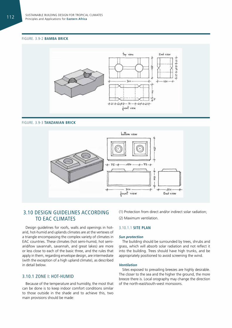
SUSTAINABLE BUILDING DESIGN FOR TROPICAL CLIMATES Principles and Applications for Eastern Africa112
Figure. 3.9-2 bamba brIck
Figure. 3.9-3 tanzanIan brIck
3.10 desIgn guIdelInes accordIng To eac clImaTes
Design guidelines for roofs, walls and openings in hot-arid, hot-humid and uplands climates are at the vertexes of a triangle encompassing the complex variety of climates in EAC countries. These climates (hot semi-humid, hot semi-arid/low savannah, savannah, and great lakes) are more or less close to each of the basic three, and the rules that apply in them, regarding envelope design, are intermediate (with the exception of a high upland climate), as described in detail below.
3.10.1 Zone I: hoT-humId
Because of the temperature and humidity, the most that can be done is to keep indoor comfort conditions similar to those outside in the shade and to achieve this, two main provisions should be made:
(1) Protection from direct and/or indirect solar radiation;
(2) Maximum ventilation.
3.10.1.1 sIte plan
Sun protectionThe building should be surrounded by trees, shrubs and
grass, which will absorb solar radiation and not reflect it into the building. Trees should have high trunks, and be appropriately positioned to avoid screening the wind.
Ventilation Sites exposed to prevailing breezes are highly desirable.
The closer to the sea and the higher the ground, the more breeze there is. Local orography may change the direction of the north-east/south-west monsoons.
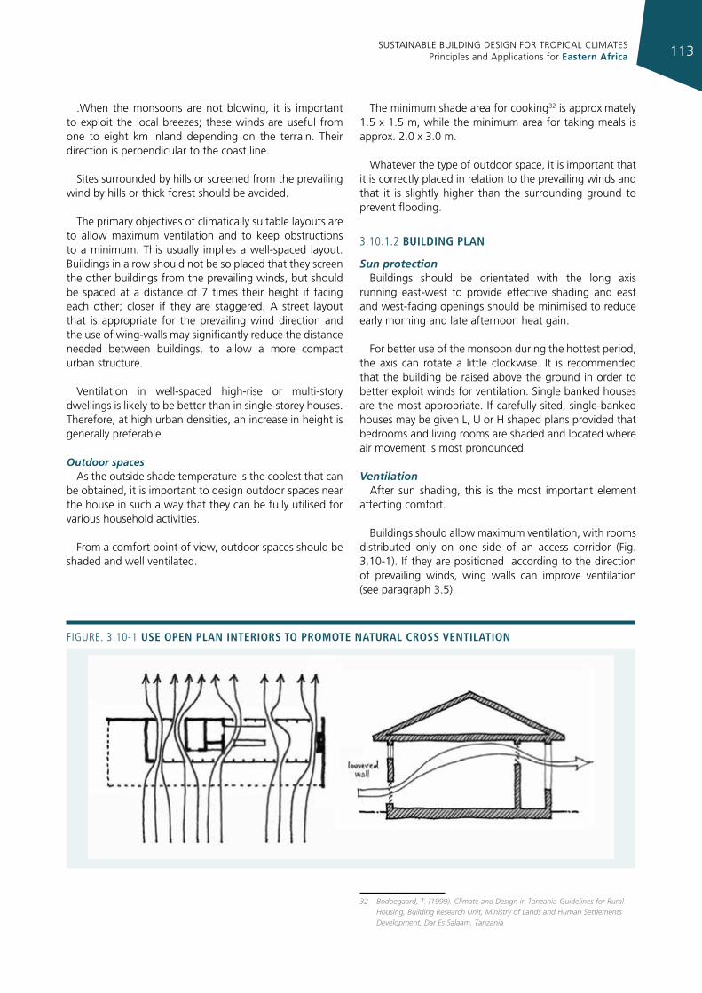
SUSTAINABLE BUILDING DESIGN FOR TROPICAL CLIMATES Principles and Applications for Eastern Africa 113
.When the monsoons are not blowing, it is important to exploit the local breezes; these winds are useful from one to eight km inland depending on the terrain. Their direction is perpendicular to the coast line.
Sites surrounded by hills or screened from the prevailing wind by hills or thick forest should be avoided.
The primary objectives of climatically suitable layouts are to allow maximum ventilation and to keep obstructions to a minimum. This usually implies a well-spaced layout. Buildings in a row should not be so placed that they screen the other buildings from the prevailing winds, but should be spaced at a distance of 7 times their height if facing each other; closer if they are staggered. A street layout that is appropriate for the prevailing wind direction and the use of wing-walls may significantly reduce the distance needed between buildings, to allow a more compact urban structure.
Ventilation in well-spaced high-rise or multi-story dwellings is likely to be better than in single-storey houses. Therefore, at high urban densities, an increase in height is generally preferable.
Outdoor spacesAs the outside shade temperature is the coolest that can
be obtained, it is important to design outdoor spaces near the house in such a way that they can be fully utilised for various household activities.
From a comfort point of view, outdoor spaces should be shaded and well ventilated.
The minimum shade area for cooking32 is approximately 1.5 x 1.5 m, while the minimum area for taking meals is approx. 2.0 x 3.0 m.
Whatever the type of outdoor space, it is important that it is correctly placed in relation to the prevailing winds and that it is slightly higher than the surrounding ground to prevent flooding.
3.10.1.2 buIldIng plan
Sun protection Buildings should be orientated with the long axis
running east-west to provide effective shading and east and west-facing openings should be minimised to reduce early morning and late afternoon heat gain.
For better use of the monsoon during the hottest period, the axis can rotate a little clockwise. It is recommended that the building be raised above the ground in order to better exploit winds for ventilation. Single banked houses are the most appropriate. If carefully sited, single-banked houses may be given L, U or H shaped plans provided that bedrooms and living rooms are shaded and located where air movement is most pronounced.
Ventilation After sun shading, this is the most important element
affecting comfort.
Buildings should allow maximum ventilation, with rooms distributed only on one side of an access corridor (Fig. 3.10-1). If they are positioned according to the direction of prevailing winds, wing walls can improve ventilation (see paragraph 3.5).
32 Bodoegaard, T. (1999). Climate and Design in Tanzania-Guidelines for Rural Housing, Building Research Unit, Ministry of Lands and Human Settlements Development, Dar Es Salaam, Tanzania
Figure. 3.10-1 use open plan InterIors to promote natural cross ventIlatIon
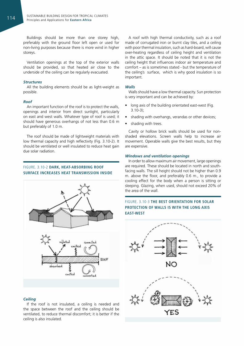
SUSTAINABLE BUILDING DESIGN FOR TROPICAL CLIMATES Principles and Applications for Eastern Africa114
Buildings should be more than one storey high, preferably with the ground floor left open or used for non-living purposes because there is more wind in higher storeys.
Ventilation openings at the top of the exterior walls should be provided, so that heated air close to the underside of the ceiling can be regularly evacuated.
StructuresAll the building elements should be as light-weight as
possible.
Roof An important function of the roof is to protect the walls,
openings and interior from direct sunlight, particularly on east and west walls. Whatever type of roof is used; it should have generous overhangs of not less than 0.6 m but preferably of 1.0 m.
The roof should be made of lightweight materials with low thermal capacity and high reflectivity (Fig. 3.10-2). It should be ventilated or well insulated to reduce heat gain due solar radiation.
CeilingIf the roof is not insulated, a ceiling is needed and
the space between the roof and the ceiling should be ventilated, to reduce thermal discomfort; it is better if the ceiling is also insulated.
A roof with high thermal conductivity, such as a roof made of corrugated iron or burnt clay tiles, and a ceiling with poor thermal insulation, such as hard-board, will cause over-heating regardless of ceiling height and ventilation in the attic space. It should be noted that it is not the ceiling height that influences indoor air temperature and comfort – as is sometimes stated - but the temperature of the ceiling’s surface, which is why good insulation is so important.
Walls Walls should have a low thermal capacity. Sun protection
is very important and can be achieved by:
• longaxisofthebuildingorientatedeast-west(Fig.3.10-3);
• shadingwithoverhangs,verandasorotherdevices;
• shadingwithtrees.
Cavity or hollow brick walls should be used for non-shaded elevations. Screen walls help to increase air movement. Operable walls give the best results, but they are expensive.
Windows and ventilation openings In order to allow maximum air movement, large openings
are required. These should be located in north and south-facing walls. The sill height should not be higher than 0.9 m. above the floor, and preferably 0.6 m., to provide a cooling effect for the body when a person is sitting or sleeping. Glazing, when used, should not exceed 20% of the area of the wall.
Figure. 3.10-2 dark, heat-absorbIng roof surface Increases heat transmIssIon InsIde
Figure. 3.10-3 the best orIentatIon for solar protectIon of Walls Is WIth the long axIs east-West
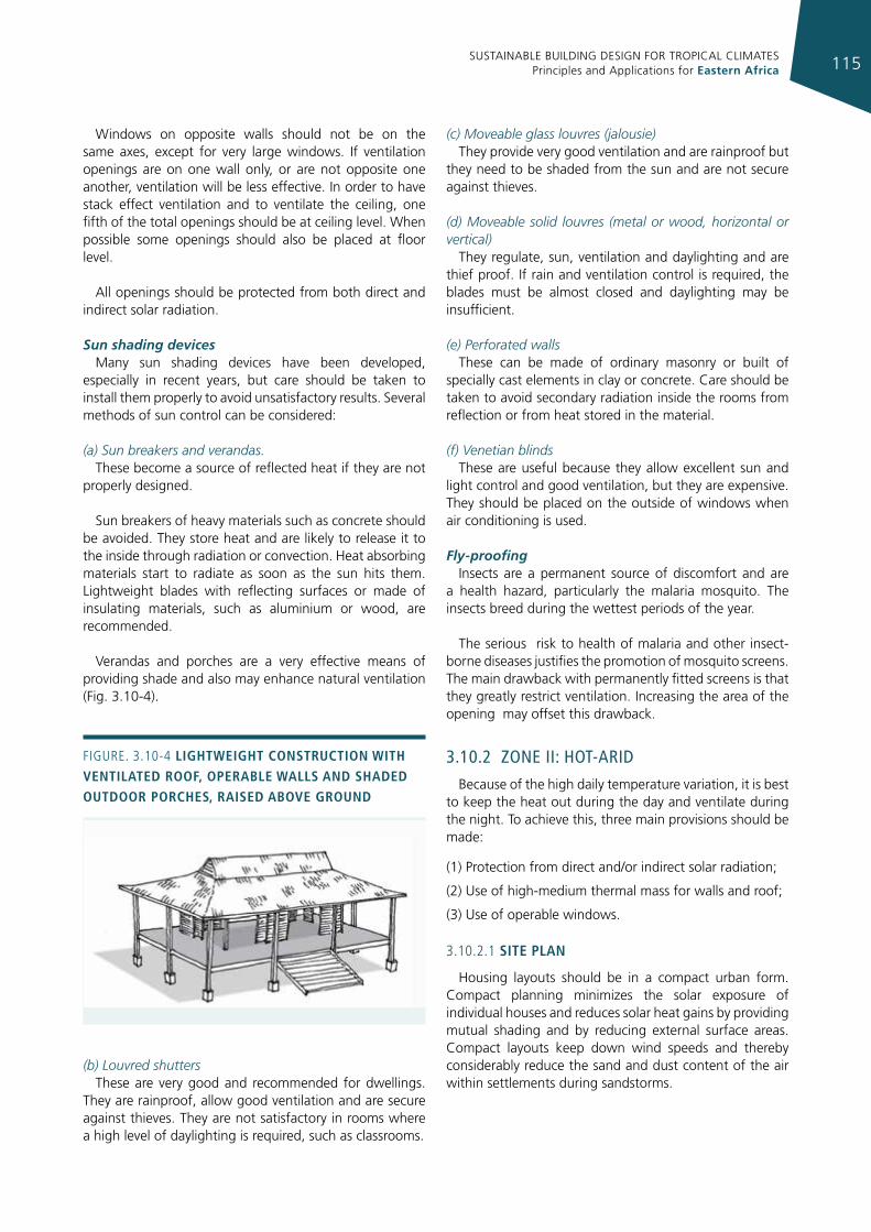
SUSTAINABLE BUILDING DESIGN FOR TROPICAL CLIMATES Principles and Applications for Eastern Africa 115
Windows on opposite walls should not be on the same axes, except for very large windows. If ventilation openings are on one wall only, or are not opposite one another, ventilation will be less effective. In order to have stack effect ventilation and to ventilate the ceiling, one fifth of the total openings should be at ceiling level. When possible some openings should also be placed at floor level.
All openings should be protected from both direct and indirect solar radiation.
Sun shading devicesMany sun shading devices have been developed,
especially in recent years, but care should be taken to install them properly to avoid unsatisfactory results. Several methods of sun control can be considered:
(a) Sun breakers and verandas. These become a source of reflected heat if they are not
properly designed.
Sun breakers of heavy materials such as concrete should be avoided. They store heat and are likely to release it to the inside through radiation or convection. Heat absorbing materials start to radiate as soon as the sun hits them. Lightweight blades with reflecting surfaces or made of insulating materials, such as aluminium or wood, are recommended.
Verandas and porches are a very effective means of providing shade and also may enhance natural ventilation (Fig. 3.10-4).
(b) Louvred shutters These are very good and recommended for dwellings.
They are rainproof, allow good ventilation and are secure against thieves. They are not satisfactory in rooms where a high level of daylighting is required, such as classrooms.
(c) Moveable glass louvres (jalousie) They provide very good ventilation and are rainproof but
they need to be shaded from the sun and are not secure against thieves.
(d) Moveable solid louvres (metal or wood, horizontal or vertical)
They regulate, sun, ventilation and daylighting and are thief proof. If rain and ventilation control is required, the blades must be almost closed and daylighting may be insufficient.
(e) Perforated walls These can be made of ordinary masonry or built of
specially cast elements in clay or concrete. Care should be taken to avoid secondary radiation inside the rooms from reflection or from heat stored in the material.
(f) Venetian blinds These are useful because they allow excellent sun and
light control and good ventilation, but they are expensive. They should be placed on the outside of windows when air conditioning is used.
Fly-proofing Insects are a permanent source of discomfort and are
a health hazard, particularly the malaria mosquito. The insects breed during the wettest periods of the year.
The serious risk to health of malaria and other insect-borne diseases justifies the promotion of mosquito screens. The main drawback with permanently fitted screens is that they greatly restrict ventilation. Increasing the area of the opening may offset this drawback.
3.10.2 Zone II: hoT-arId
Because of the high daily temperature variation, it is best to keep the heat out during the day and ventilate during the night. To achieve this, three main provisions should be made:
(1) Protection from direct and/or indirect solar radiation;
(2) Use of high-medium thermal mass for walls and roof;
(3) Use of operable windows.
3.10.2.1 sIte plan
Housing layouts should be in a compact urban form. Compact planning minimizes the solar exposure of individual houses and reduces solar heat gains by providing mutual shading and by reducing external surface areas. Compact layouts keep down wind speeds and thereby considerably reduce the sand and dust content of the air within settlements during sandstorms.
Figure. 3.10-4 lIghtWeIght constructIon WIth ventIlated roof, operable Walls and shaded outdoor porches, raIsed above ground
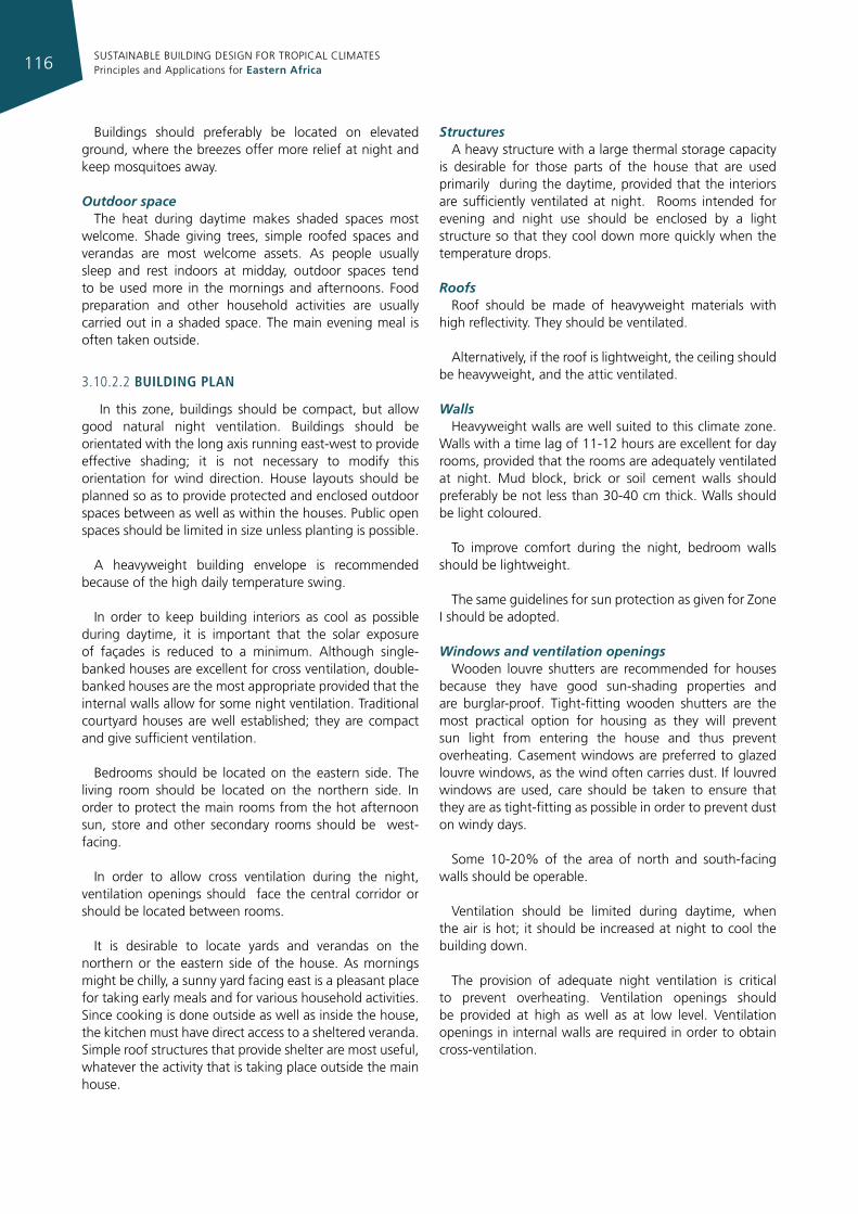
SUSTAINABLE BUILDING DESIGN FOR TROPICAL CLIMATES Principles and Applications for Eastern Africa116
Buildings should preferably be located on elevated ground, where the breezes offer more relief at night and keep mosquitoes away.
Outdoor spaceThe heat during daytime makes shaded spaces most
welcome. Shade giving trees, simple roofed spaces and verandas are most welcome assets. As people usually sleep and rest indoors at midday, outdoor spaces tend to be used more in the mornings and afternoons. Food preparation and other household activities are usually carried out in a shaded space. The main evening meal is often taken outside.
3.10.2.2 buIldIng plan
In this zone, buildings should be compact, but allow good natural night ventilation. Buildings should be orientated with the long axis running east-west to provide effective shading; it is not necessary to modify this orientation for wind direction. House layouts should be planned so as to provide protected and enclosed outdoor spaces between as well as within the houses. Public open spaces should be limited in size unless planting is possible.
A heavyweight building envelope is recommended because of the high daily temperature swing.
In order to keep building interiors as cool as possible during daytime, it is important that the solar exposure of façades is reduced to a minimum. Although single-banked houses are excellent for cross ventilation, double-banked houses are the most appropriate provided that the internal walls allow for some night ventilation. Traditional courtyard houses are well established; they are compact and give sufficient ventilation.
Bedrooms should be located on the eastern side. The living room should be located on the northern side. In order to protect the main rooms from the hot afternoon sun, store and other secondary rooms should be west-facing.
In order to allow cross ventilation during the night, ventilation openings should face the central corridor or should be located between rooms.
It is desirable to locate yards and verandas on the northern or the eastern side of the house. As mornings might be chilly, a sunny yard facing east is a pleasant place for taking early meals and for various household activities. Since cooking is done outside as well as inside the house, the kitchen must have direct access to a sheltered veranda. Simple roof structures that provide shelter are most useful, whatever the activity that is taking place outside the main house.
StructuresA heavy structure with a large thermal storage capacity
is desirable for those parts of the house that are used primarily during the daytime, provided that the interiors are sufficiently ventilated at night. Rooms intended for evening and night use should be enclosed by a light structure so that they cool down more quickly when the temperature drops.
Roofs Roof should be made of heavyweight materials with
high reflectivity. They should be ventilated.
Alternatively, if the roof is lightweight, the ceiling should be heavyweight, and the attic ventilated.
WallsHeavyweight walls are well suited to this climate zone.
Walls with a time lag of 11-12 hours are excellent for day rooms, provided that the rooms are adequately ventilated at night. Mud block, brick or soil cement walls should preferably be not less than 30-40 cm thick. Walls should be light coloured.
To improve comfort during the night, bedroom walls should be lightweight.
The same guidelines for sun protection as given for Zone I should be adopted.
Windows and ventilation openings Wooden louvre shutters are recommended for houses
because they have good sun-shading properties and are burglar-proof. Tight-fitting wooden shutters are the most practical option for housing as they will prevent sun light from entering the house and thus prevent overheating. Casement windows are preferred to glazed louvre windows, as the wind often carries dust. If louvred windows are used, care should be taken to ensure that they are as tight-fitting as possible in order to prevent dust on windy days.
Some 10-20% of the area of north and south-facing walls should be operable.
Ventilation should be limited during daytime, when the air is hot; it should be increased at night to cool the building down.
The provision of adequate night ventilation is critical to prevent overheating. Ventilation openings should be provided at high as well as at low level. Ventilation openings in internal walls are required in order to obtain cross-ventilation.
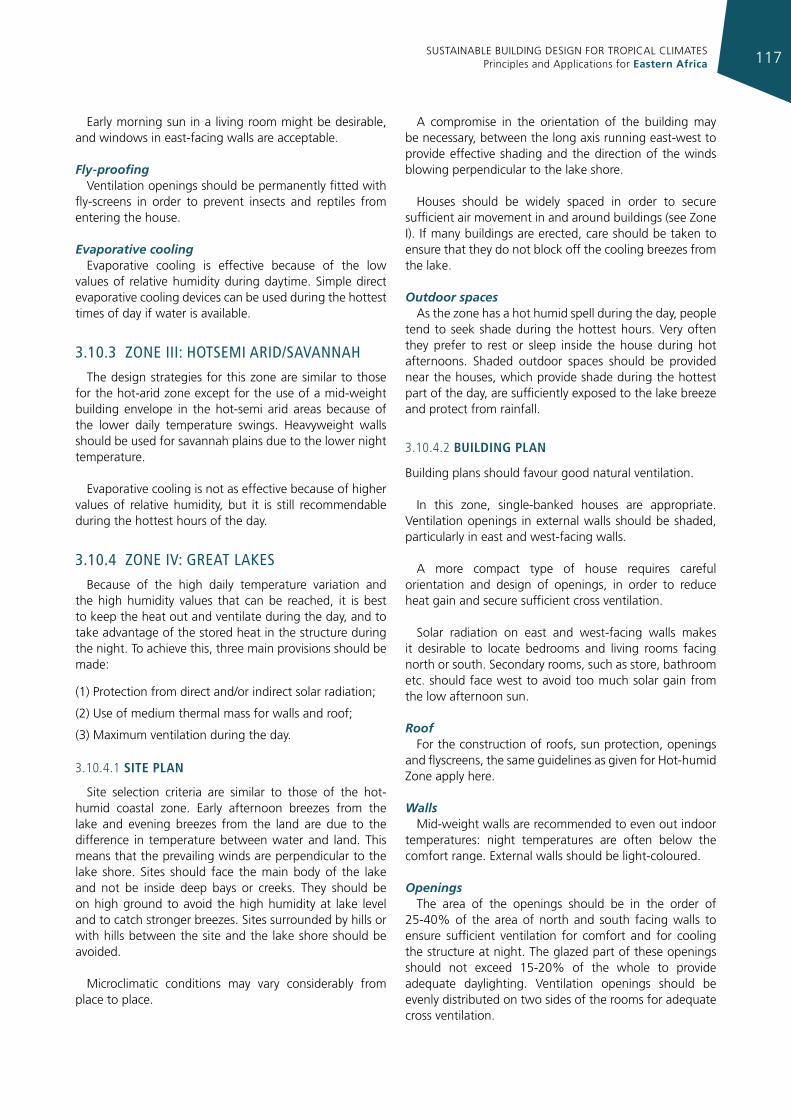
SUSTAINABLE BUILDING DESIGN FOR TROPICAL CLIMATES Principles and Applications for Eastern Africa 117
Early morning sun in a living room might be desirable, and windows in east-facing walls are acceptable.
Fly-proofingVentilation openings should be permanently fitted with
fly-screens in order to prevent insects and reptiles from entering the house.
Evaporative coolingEvaporative cooling is effective because of the low
values of relative humidity during daytime. Simple direct evaporative cooling devices can be used during the hottest times of day if water is available.
3.10.3 Zone III: hoTsemI arId/savannah
The design strategies for this zone are similar to those for the hot-arid zone except for the use of a mid-weight building envelope in the hot-semi arid areas because of the lower daily temperature swings. Heavyweight walls should be used for savannah plains due to the lower night temperature.
Evaporative cooling is not as effective because of higher values of relative humidity, but it is still recommendable during the hottest hours of the day.
3.10.4 Zone Iv: greaT lakes
Because of the high daily temperature variation and the high humidity values that can be reached, it is best to keep the heat out and ventilate during the day, and to take advantage of the stored heat in the structure during the night. To achieve this, three main provisions should be made:
(1) Protection from direct and/or indirect solar radiation;
(2) Use of medium thermal mass for walls and roof;
(3) Maximum ventilation during the day.
3.10.4.1 sIte plan
Site selection criteria are similar to those of the hot-humid coastal zone. Early afternoon breezes from the lake and evening breezes from the land are due to the difference in temperature between water and land. This means that the prevailing winds are perpendicular to the lake shore. Sites should face the main body of the lake and not be inside deep bays or creeks. They should be on high ground to avoid the high humidity at lake level and to catch stronger breezes. Sites surrounded by hills or with hills between the site and the lake shore should be avoided.
Microclimatic conditions may vary considerably from place to place.
A compromise in the orientation of the building may be necessary, between the long axis running east-west to provide effective shading and the direction of the winds blowing perpendicular to the lake shore.
Houses should be widely spaced in order to secure sufficient air movement in and around buildings (see Zone I). If many buildings are erected, care should be taken to ensure that they do not block off the cooling breezes from the lake.
Outdoor spaces As the zone has a hot humid spell during the day, people
tend to seek shade during the hottest hours. Very often they prefer to rest or sleep inside the house during hot afternoons. Shaded outdoor spaces should be provided near the houses, which provide shade during the hottest part of the day, are sufficiently exposed to the lake breeze and protect from rainfall.
3.10.4.2 buIldIng plan
Building plans should favour good natural ventilation.
In this zone, single-banked houses are appropriate. Ventilation openings in external walls should be shaded, particularly in east and west-facing walls.
A more compact type of house requires careful orientation and design of openings, in order to reduce heat gain and secure sufficient cross ventilation.
Solar radiation on east and west-facing walls makes it desirable to locate bedrooms and living rooms facing north or south. Secondary rooms, such as store, bathroom etc. should face west to avoid too much solar gain from the low afternoon sun.
RoofFor the construction of roofs, sun protection, openings
and flyscreens, the same guidelines as given for Hot-humid Zone apply here.
WallsMid-weight walls are recommended to even out indoor
temperatures: night temperatures are often below the comfort range. External walls should be light-coloured.
Openings The area of the openings should be in the order of
25-40% of the area of north and south facing walls to ensure sufficient ventilation for comfort and for cooling the structure at night. The glazed part of these openings should not exceed 15-20% of the whole to provide adequate daylighting. Ventilation openings should be evenly distributed on two sides of the rooms for adequate cross ventilation.
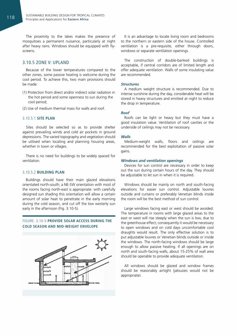
SUSTAINABLE BUILDING DESIGN FOR TROPICAL CLIMATES Principles and Applications for Eastern Africa118
The proximity to the lakes makes the presence of mosquitoes a permanent nuisance, particularly at night after heavy rains. Windows should be equipped with fly-screens.
3.10.5 Zone v: upland
Because of the lower temperatures compared to the other zones, some passive heating is welcome during the cool period. To achieve this, two main provisions should be made:
(1) Protection from direct and/or indirect solar radiation in the hot period and some openness to sun during the cool period;
(2) Use of medium thermal mass for walls and roof.
3.10.5.1 sIte plan
Sites should be selected so as to provide shelter against prevailing winds and cold air pockets in ground depressions. The varied topography and vegetation should be utilised when locating and planning housing areas, whether in town or villages.
There is no need for buildings to be widely spaced for ventilation.
3.10.5.2 buIldIng plan
Buildings should have their main glazed elevations orientated north-south; a NE-SW orientation with most of the rooms facing north-east is appropriate: with carefully designed sun shading this orientation will allow a certain amount of solar heat to penetrate in the early morning during the cold season, and cut off the low westerly sun early in the afternoon (Fig. 3.10-5).
It is an advantage to locate living room and bedrooms to the northern or eastern side of the house. Controlled ventilation is a pre-requisite, either through doors, windows or separate ventilation openings.
The construction of double-banked buildings is acceptable, if central corridors are of limited length and offer adequate ventilation. Walls of some insulating value are recommended.
StructuresA medium weight structure is recommended. Due to
intense sunshine during the day, considerable heat will be stored in heavy structures and emitted at night to reduce the drop in temperature.
RoofRoofs can be light or heavy but they must have a
good insulation value. Ventilation of roof cavities or the underside of ceilings may not be necessary.
WallsMedium-weight walls, floors and ceilings are
recommended for the best exploitation of passive solar gains.
Windows and ventilation openings Devices for sun control are necessary in order to keep
out the sun during certain hours of the day. They should be adjustable to let sun in when it is required.
Windows should be mainly on north and south-facing elevations for easier sun control. Adjustable louvres outside and curtains or preferably Venetian blinds inside the room will be the best method of sun control.
Large windows facing east or west should be avoided. The temperature in rooms with large glazed areas to the east or west will rise steeply when the sun is low, due to the greenhouse effect; consequently it would be necessary to open windows and on cold days uncomfortable cool draughts would result. The only effective solution is to put adjustable louvres or Venetian blinds outside or inside the windows. The north-facing windows should be large enough to allow passive heating. If all openings are on north and south-facing walls, about 15-25% of wall area should be operable to provide adequate ventilation.
All windows should be glazed and window frames should be reasonably airtight (jalousies would not be appropriate).
Figure. 3.10-5 provIde solar access durIng the cold season and mId-WeIght envelope
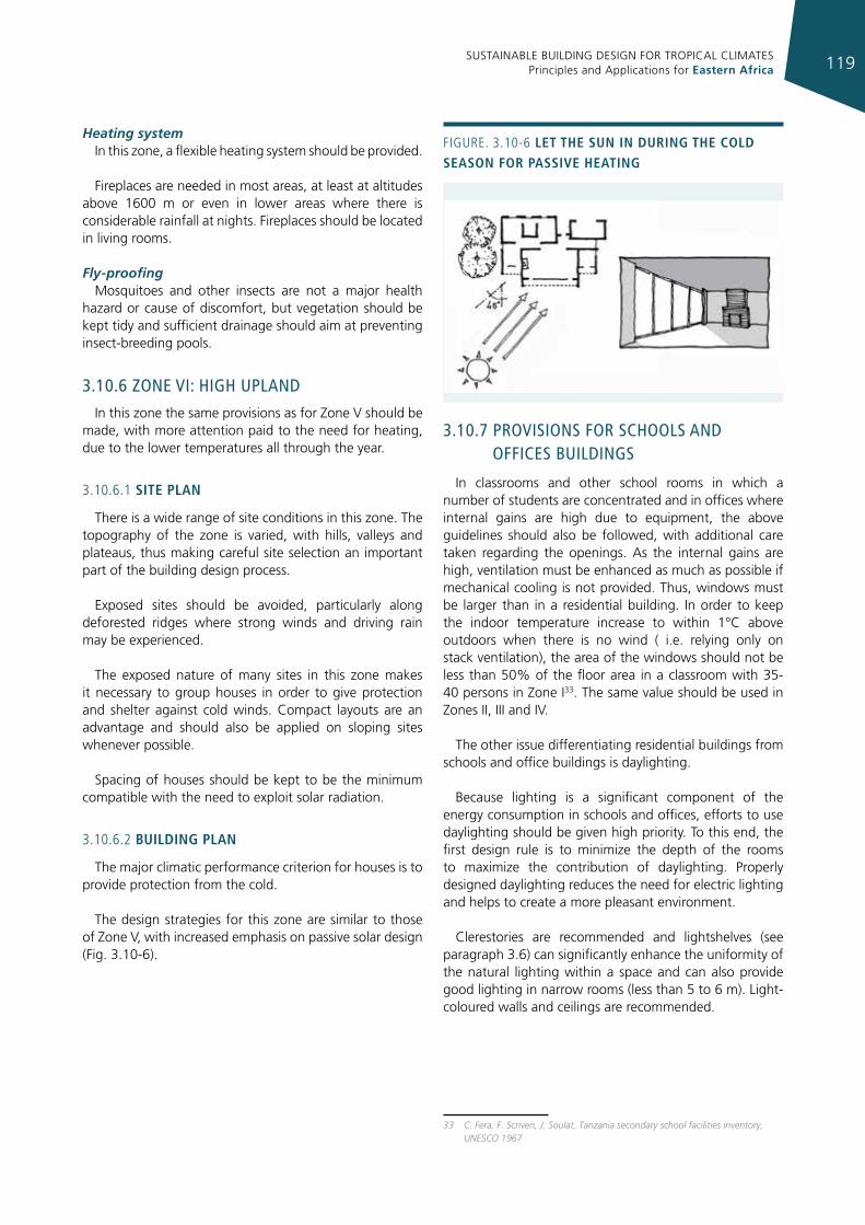
SUSTAINABLE BUILDING DESIGN FOR TROPICAL CLIMATES Principles and Applications for Eastern Africa 119
Heating systemIn this zone, a flexible heating system should be provided.
Fireplaces are needed in most areas, at least at altitudes above 1600 m or even in lower areas where there is considerable rainfall at nights. Fireplaces should be located in living rooms.
Fly-proofingMosquitoes and other insects are not a major health
hazard or cause of discomfort, but vegetation should be kept tidy and sufficient drainage should aim at preventing insect-breeding pools.
3.10.6 Zone vI: hIgh upland
In this zone the same provisions as for Zone V should be made, with more attention paid to the need for heating, due to the lower temperatures all through the year.
3.10.6.1 sIte plan
There is a wide range of site conditions in this zone. The topography of the zone is varied, with hills, valleys and plateaus, thus making careful site selection an important part of the building design process.
Exposed sites should be avoided, particularly along deforested ridges where strong winds and driving rain may be experienced.
The exposed nature of many sites in this zone makes it necessary to group houses in order to give protection and shelter against cold winds. Compact layouts are an advantage and should also be applied on sloping sites whenever possible.
Spacing of houses should be kept to be the minimum compatible with the need to exploit solar radiation.
3.10.6.2 buIldIng plan
The major climatic performance criterion for houses is to provide protection from the cold.
The design strategies for this zone are similar to those of Zone V, with increased emphasis on passive solar design (Fig. 3.10-6).
3.10.7 provIsIons for schools and offIces buIldIngs
In classrooms and other school rooms in which a number of students are concentrated and in offices where internal gains are high due to equipment, the above guidelines should also be followed, with additional care taken regarding the openings. As the internal gains are high, ventilation must be enhanced as much as possible if mechanical cooling is not provided. Thus, windows must be larger than in a residential building. In order to keep the indoor temperature increase to within 1°C above outdoors when there is no wind ( i.e. relying only on stack ventilation), the area of the windows should not be less than 50% of the floor area in a classroom with 35-40 persons in Zone I33. The same value should be used in Zones II, III and IV.
The other issue differentiating residential buildings from schools and office buildings is daylighting.
Because lighting is a significant component of the energy consumption in schools and offices, efforts to use daylighting should be given high priority. To this end, the first design rule is to minimize the depth of the rooms to maximize the contribution of daylighting. Properly designed daylighting reduces the need for electric lighting and helps to create a more pleasant environment.
Clerestories are recommended and lightshelves (see paragraph 3.6) can significantly enhance the uniformity of the natural lighting within a space and can also provide good lighting in narrow rooms (less than 5 to 6 m). Light-coloured walls and ceilings are recommended.
33 C. Fera, F. Scriven, J. Soulat, Tanzania secondary school facilities inventory, UNESCO 1967
Figure. 3.10-6 let the sun In durIng the cold season for passIve heatIng
SUSTAINABLE BUILDING DESIGN FOR TROPICAL CLIMATES Principles and Applications for Eastern Africa120
Finally, in air-conditioned non-residential buildings it is better to have light-medium weight envelopes in all climates.
3.10.8 desIgn guIdelInes summary
ZONe i: hot-humId clImate
Site plan• Housesshouldbelocatedonsitesexposedtosea
breezes; avoid sheltered sites. Trees should be used for shading.
• Layoutsshouldbeopen,sohousesshouldbewidelyspaced to allow maximum ventilation in and around buildings, which should be spaced at a distance of 7 times their height if facing each other; closer if staggered.
• Athighurbandensities,buildingheightshouldbeincreased in preference to an increase in ground coverage.
Building plan• Singlebankedhousesprovidemaximumventilation.
• Buildingsraisedabovegroundfavourventilation;aswind velocity increases with height, high-rise buildings are appropriate.
• Apartmentsinmulti-storeybuildingsexperiencebetterventilation.
• Mainelevationsshouldfacenorthandsouthandbuildings should be orientated with the long axis running east-west to provide effective shading - unless the direction of the prevailing breezes suggests an offset from this orientation - and raised above the ground.
• Shadedverandasforhousesorbalconiesforflatsareessential.
• Bedroomsshouldbelocatedupstairstoprovidemaximum access to cooling breezes and to provide a sleeping area separate from other zones that may have gained heat during the day.
Structures • Lightweightandlight-colouredorreflectiveroofand
walls (possibly operable); shaded outdoor porches.
• Ceilingshighlydesirableforheatandsoundinsulation.
• Aircavitybetweenceilingandroof,whichispermanently ventilated and provided with reflective foil to block radiant heat; roof pitch to vent roof heat gains.
• Roofoverhangsnotlessthan0.6m,preferablyaswide as 1.0 m.
• Shallowfloorplanofone-roomwidthtoallowmaximum cross ventilation.
Openings• Openingsshouldbelargeandshaded,withsillheight
not above 0.9 m.
• Thesizeshouldbepreferablyatleast50%ofnorthand south walls.
• Glazedareashouldnotexceed20%oftheareaofwall.
• Thereshouldbeverticalspaceforupwardmovementof heat from ground floor (internal stairs).
• Wing walls should be constructed to channel predominant breezes through the building.
• Allfixedshadingshouldbeinsulatedorreflectivetoavoid radiant heat gain at openings.
• Fly-proofingshouldbeinstalled.
ZONe ii: hot-arId clImate
Site plan• Housinglayoutsshouldbecompact.
• Trees,hedgesandothervegetationshouldbeplantedto reduce dust, glare and reflected heat.
Building Plan• Courtyard houses protect against hot, dry winds and
can be combined with plants and water features.
• Houseplansshouldbeinwardlookingwithroomsopening off, and roofs sloping towards the courtyard.
• Courtyardsshouldbelimitedinsize.Outdoorlivingspace should be enclosed.
• Buildingsshouldbeorientatedwiththelongaxisrunning east-west to provide effective shading; it is not necessary to modify this orientation for wind direction.
• Nobedroomshouldfacewest.
Structures• Aheavyweightbuildingenvelopeisrecommended
because of the high daily temperature swing.
• Heavystructuresaregoodfordayroomsiftheyarewell ventilated in night.
• Lightstructuresareessentialforroomsusedatnight.
• Externalsurfacesshouldbereflective.
• Roofsshouldbemadeofheavyweightmaterials,havehigh reflectivity and be ventilated. Alternatively, if the roof is lightweight, the ceiling should be heavyweight, and the attic ventilated.
Openings• Largeopeningsmaybeinappropriate,unlesswell
shaded.
• Ventilationshouldbecontrolledtoensurethatthebuilding is not heated when the inside temperature is lower than the outside temperature on a hot day, and that it is cooled during the night.
SUSTAINABLE BUILDING DESIGN FOR TROPICAL CLIMATES Principles and Applications for Eastern Africa 121
• Heat gain is reduced as much as possible with no or small windows on the eastern or western sides and small, well-shaded windows elsewhere.
• Some10-20%oftheareaofnorthandsouth-facingwalls should be operable.
• Highandlowlevelopeningsshouldbecreatedinwalls bordering courtyards to facilitate air movement.
• Smallopeningsinperimeterwallsarerequiredforcross ventilation.
• Shutteredandpermanentopeningsarepreferableto glazed windows except where exclusion of dust is required.
• Fly-proofingisrequiredwheremosquitoesaretroublesome.
Cooling• Evaporativecoolingshouldbeusedtoimprove
comfort when the relative humidity is low. Consideration should also be given to the sustainability of available water resources.
ZONe iii: hot-semI arId/savannah clImate
As for to the hot-arid zone except:
• Medium-weightbuildingenvelopeinhot-semiaridparts and heavyweight walls for savannah plains.
• Evaporative cooling not as effective because of higher relative humidity.
ZONe iV: great lakes clImate
Site planSite selection criteria are similar to those of the Hot-
humid Coastal Zone. Care should be taken to ensure free air movement yet ensure minimum solar exposure:
• Exposedsitesaredesirable.Sitesindepressions,oronthe leeward side of hills should be avoided.
• Housesshouldbewidelyspacedinordertosecuresufficient air movement in and around buildings.
Building plan• Aswindvelocityincreaseswithheight,high-rise
buildings are appropriate.
• Thetypeofhouseislargelydeterminedbytheneedfor cross ventilation.
• Mainelevationsshouldfacenorthandsouth.
• Single-bankedhousesraisedabovegroundareappropriate.
• Wellplacedopeningsininternalwallsandshadedpermanent openings in east and west-facing walls are effective for cross ventilation in double banked houses.
• Bedroomsandlivingroomsshouldfacenorthorsouth.
• Secondaryrooms,suchasstorerooms,bathroometc.,should face west.
StructuresFor roof construction, sun protection, openings and
flyscreens, the same guidelines as for hot-humid zones apply, except:
• Mid-weightwallsarerecommendedtoevenoutindoor temperatures: night temperatures are often below the comfort range.
• Externalwallsshouldbelight-coloured.
Openings• Openingsshouldoccupy25-40%oftheareaofnorth
and south -facing walls, and the glazed part should not exceed 15-20% of the whole.
• Ventilationopeningsshouldbeevenlydistributedontwo sides of the rooms for adequate cross ventilation.
• Fly-proofingisessential.
ZONeS V-Vi: upland and hIgh upland clImateSite plan• Shelteredsitesdesirable.
• Compactlayoutsthatprotectratherthanexposehouses to wind required.
• Terracedhousesappropriate.
• Outdoorspacesadjacenttohouse,exposedtothesun, but protected from wind, advantageous.
Building plan• Compactdouble-bankedformsaredesirable.
• Buildingsshouldhavetheirmainglazedelevationsoriented north-south; NE-SW orientation with most of the rooms facing north-east is also appropriate.
• Floorplanshouldbeorganisedsothatthesunpenetrates into daytime spaces on cool days. Living room and bedrooms should be located on the north or east sides of the house.
• Controlledventilationisapre-requisite.
Structures• Mediumweightwallsandroofsarehighlydesirable.
• Massiveinteriormaterialtostorepassiveheatinthe cool season and night “coolness” in the warm season.
Openings• 15-25%ofNorthandSouthwallareashouldbe
operable to provide adequate ventilation.
• Windowsshouldroughlybe50%ofthefloorareaofthe house.
• Windowsshouldbemainlyonnorthandsouth-facingelevations.
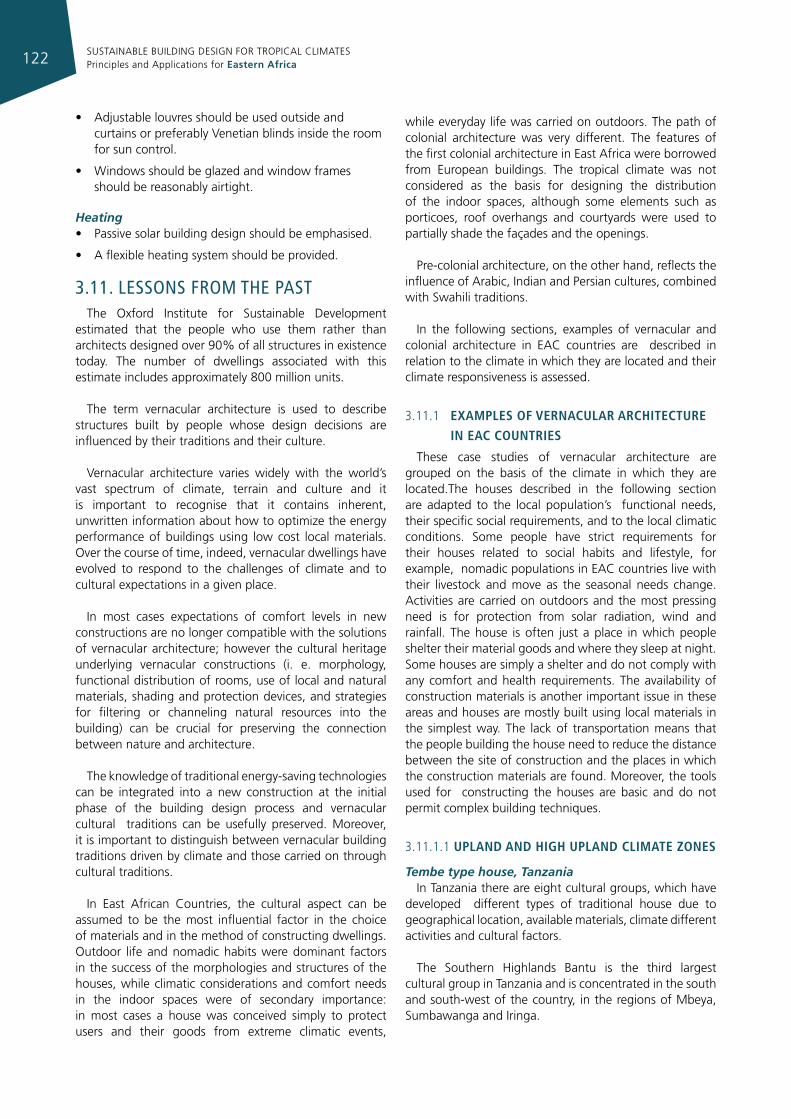
SUSTAINABLE BUILDING DESIGN FOR TROPICAL CLIMATES Principles and Applications for Eastern Africa122
• Adjustablelouvres should be used outside and curtains or preferably Venetian blinds inside the room for sun control.
• Windowsshouldbeglazedandwindowframesshould be reasonably airtight.
Heating• Passivesolarbuildingdesignshouldbeemphasised.
• Aflexibleheatingsystemshouldbeprovided.
3.11. lessons from The pasTThe Oxford Institute for Sustainable Development
estimated that the people who use them rather than architects designed over 90% of all structures in existence today. The number of dwellings associated with this estimate includes approximately 800 million units.
The term vernacular architecture is used to describe structures built by people whose design decisions are influenced by their traditions and their culture.
Vernacular architecture varies widely with the world’s vast spectrum of climate, terrain and culture and it is important to recognise that it contains inherent, unwritten information about how to optimize the energy performance of buildings using low cost local materials. Over the course of time, indeed, vernacular dwellings have evolved to respond to the challenges of climate and to cultural expectations in a given place.
In most cases expectations of comfort levels in new constructions are no longer compatible with the solutions of vernacular architecture; however the cultural heritage underlying vernacular constructions (i. e. morphology, functional distribution of rooms, use of local and natural materials, shading and protection devices, and strategies for filtering or channeling natural resources into the building) can be crucial for preserving the connection between nature and architecture.
The knowledge of traditional energy-saving technologies can be integrated into a new construction at the initial phase of the building design process and vernacular cultural traditions can be usefully preserved. Moreover, it is important to distinguish between vernacular building traditions driven by climate and those carried on through cultural traditions.
In East African Countries, the cultural aspect can be assumed to be the most influential factor in the choice of materials and in the method of constructing dwellings. Outdoor life and nomadic habits were dominant factors in the success of the morphologies and structures of the houses, while climatic considerations and comfort needs in the indoor spaces were of secondary importance: in most cases a house was conceived simply to protect users and their goods from extreme climatic events,
while everyday life was carried on outdoors. The path of colonial architecture was very different. The features of the first colonial architecture in East Africa were borrowed from European buildings. The tropical climate was not considered as the basis for designing the distribution of the indoor spaces, although some elements such as porticoes, roof overhangs and courtyards were used to partially shade the façades and the openings.
Pre-colonial architecture, on the other hand, reflects the influence of Arabic, Indian and Persian cultures, combined with Swahili traditions.
In the following sections, examples of vernacular and colonial architecture in EAC countries are described in relation to the climate in which they are located and their climate responsiveness is assessed.
3.11.1 examples of vernacular archItecture
In eac countrIes
These case studies of vernacular architecture are grouped on the basis of the climate in which they are located.The houses described in the following section are adapted to the local population’s functional needs, their specific social requirements, and to the local climatic conditions. Some people have strict requirements for their houses related to social habits and lifestyle, for example, nomadic populations in EAC countries live with their livestock and move as the seasonal needs change. Activities are carried on outdoors and the most pressing need is for protection from solar radiation, wind and rainfall. The house is often just a place in which people shelter their material goods and where they sleep at night. Some houses are simply a shelter and do not comply with any comfort and health requirements. The availability of construction materials is another important issue in these areas and houses are mostly built using local materials in the simplest way. The lack of transportation means that the people building the house need to reduce the distance between the site of construction and the places in which the construction materials are found. Moreover, the tools used for constructing the houses are basic and do not permit complex building techniques.
3.11.1.1 upland and hIgh upland clImate zones
Tembe type house, TanzaniaIn Tanzania there are eight cultural groups, which have
developed different types of traditional house due to geographical location, available materials, climate different activities and cultural factors.
The Southern Highlands Bantu is the third largest cultural group in Tanzania and is concentrated in the south and south-west of the country, in the regions of Mbeya, Sumbawanga and Iringa.
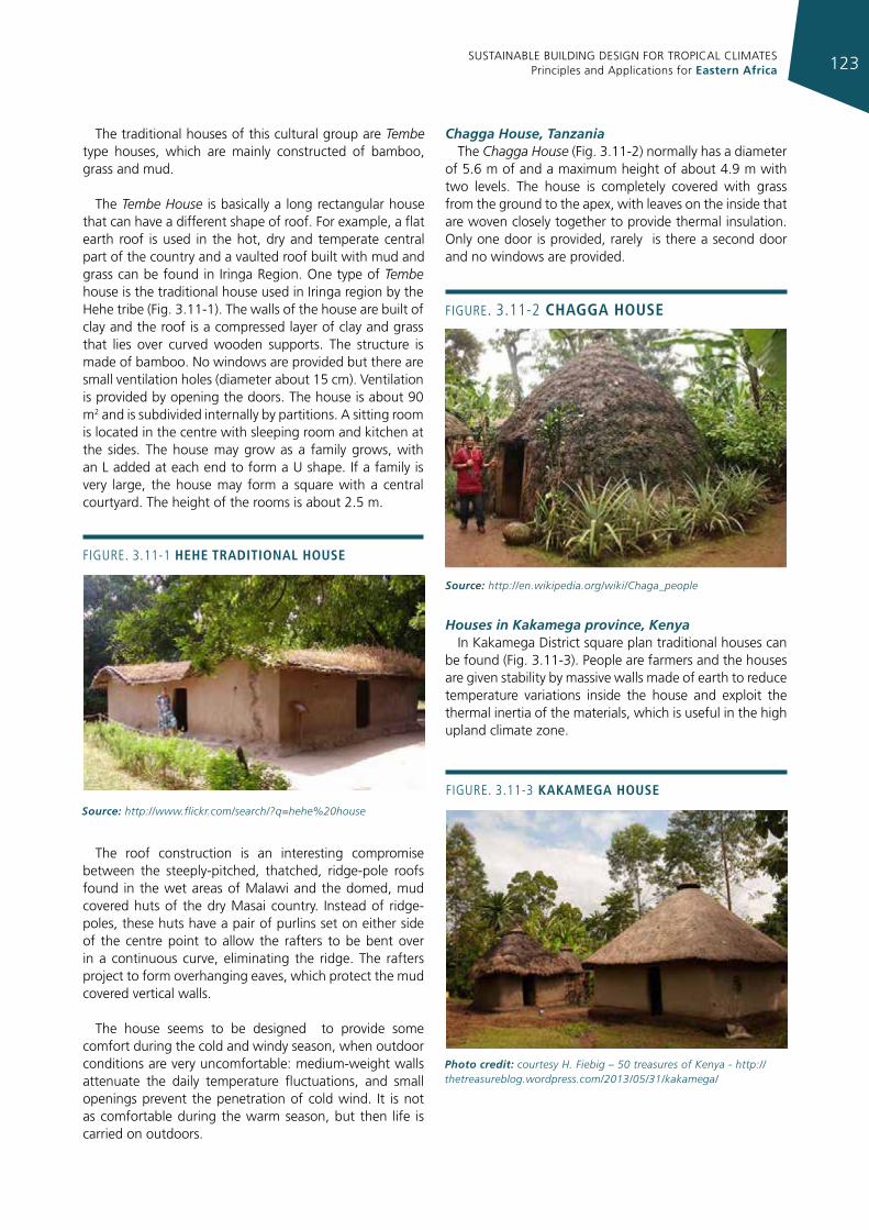
SUSTAINABLE BUILDING DESIGN FOR TROPICAL CLIMATES Principles and Applications for Eastern Africa 123
The traditional houses of this cultural group are Tembe type houses, which are mainly constructed of bamboo, grass and mud.
The Tembe House is basically a long rectangular house that can have a different shape of roof. For example, a flat earth roof is used in the hot, dry and temperate central part of the country and a vaulted roof built with mud and grass can be found in Iringa Region. One type of Tembe house is the traditional house used in Iringa region by the Hehe tribe (Fig. 3.11-1). The walls of the house are built of clay and the roof is a compressed layer of clay and grass that lies over curved wooden supports. The structure is made of bamboo. No windows are provided but there are small ventilation holes (diameter about 15 cm). Ventilation is provided by opening the doors. The house is about 90 m2 and is subdivided internally by partitions. A sitting room is located in the centre with sleeping room and kitchen at the sides. The house may grow as a family grows, with an L added at each end to form a U shape. If a family is very large, the house may form a square with a central courtyard. The height of the rooms is about 2.5 m.
The roof construction is an interesting compromise between the steeply-pitched, thatched, ridge-pole roofs found in the wet areas of Malawi and the domed, mud covered huts of the dry Masai country. Instead of ridge-poles, these huts have a pair of purlins set on either side of the centre point to allow the rafters to be bent over in a continuous curve, eliminating the ridge. The rafters project to form overhanging eaves, which protect the mud covered vertical walls.
The house seems to be designed to provide some comfort during the cold and windy season, when outdoor conditions are very uncomfortable: medium-weight walls attenuate the daily temperature fluctuations, and small openings prevent the penetration of cold wind. It is not as comfortable during the warm season, but then life is carried on outdoors.
Chagga House, TanzaniaThe Chagga House (Fig. 3.11-2) normally has a diameter
of 5.6 m of and a maximum height of about 4.9 m with two levels. The house is completely covered with grass from the ground to the apex, with leaves on the inside that are woven closely together to provide thermal insulation. Only one door is provided, rarely is there a second door and no windows are provided.
Houses in Kakamega province, KenyaIn Kakamega District square plan traditional houses can
be found (Fig. 3.11-3). People are farmers and the houses are given stability by massive walls made of earth to reduce temperature variations inside the house and exploit the thermal inertia of the materials, which is useful in the high upland climate zone.
Figure. 3.11-1 hehe tradItIonal house
Source: http://www.flickr.com/search/?q=hehe%20house
Figure. 3.11-2 chagga house
Source: http://en.wikipedia.org/wiki/Chaga_people
Figure. 3.11-3 kakamega house
Photo credit: courtesy H. Fiebig – 50 treasures of Kenya - http://thetreasureblog.wordpress.com/2013/05/31/kakamega/
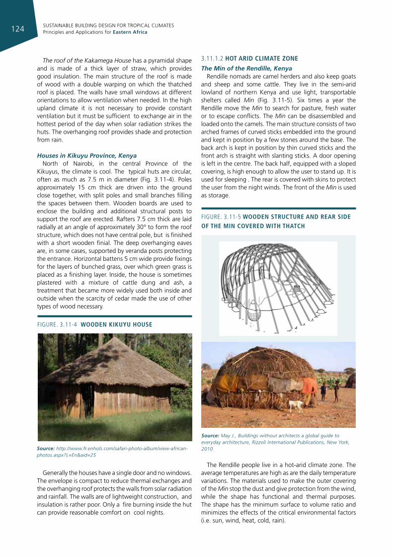
SUSTAINABLE BUILDING DESIGN FOR TROPICAL CLIMATES Principles and Applications for Eastern Africa124
The roof of the Kakamega House has a pyramidal shape and is made of a thick layer of straw, which provides good insulation. The main structure of the roof is made of wood with a double warping on which the thatched roof is placed. The walls have small windows at different orientations to allow ventilation when needed. In the high upland climate it is not necessary to provide constant ventilation but it must be sufficient to exchange air in the hottest period of the day when solar radiation strikes the huts. The overhanging roof provides shade and protection from rain.
Houses in Kikuyu Province, KenyaNorth of Nairobi, in the central Province of the
Kikuyus, the climate is cool. The typical huts are circular, often as much as 7.5 m in diameter (Fig. 3.11-4). Poles approximately 15 cm thick are driven into the ground close together, with split poles and small branches filling the spaces between them. Wooden boards are used to enclose the building and additional structural posts to support the roof are erected. Rafters 7.5 cm thick are laid radially at an angle of approximately 30° to form the roof structure, which does not have central pole, but is finished with a short wooden finial. The deep overhanging eaves are, in some cases, supported by veranda posts protecting the entrance. Horizontal battens 5 cm wide provide fixings for the layers of bunched grass, over which green grass is placed as a finishing layer. Inside, the house is sometimes plastered with a mixture of cattle dung and ash, a treatment that became more widely used both inside and outside when the scarcity of cedar made the use of other types of wood necessary.
Generally the houses have a single door and no windows. The envelope is compact to reduce thermal exchanges and the overhanging roof protects the walls from solar radiation and rainfall. The walls are of lightweight construction, and insulation is rather poor. Only a fire burning inside the hut can provide reasonable comfort on cool nights.
3.11.1.2 hot arId clImate zone
The Min of the Rendille, KenyaRendille nomads are camel herders and also keep goats
and sheep and some cattle. They live in the semi-arid lowland of northern Kenya and use light, transportable shelters called Min (Fig. 3.11-5). Six times a year the Rendille move the Min to search for pasture, fresh water or to escape conflicts. The Min can be disassembled and loaded onto the camels. The main structure consists of two arched frames of curved sticks embedded into the ground and kept in position by a few stones around the base. The back arch is kept in position by thin curved sticks and the front arch is straight with slanting sticks. A door opening is left in the centre. The back half, equipped with a sloped covering, is high enough to allow the user to stand up. It is used for sleeping . The rear is covered with skins to protect the user from the night winds. The front of the Min is used as storage.
The Rendille people live in a hot-arid climate zone. The average temperatures are high as are the daily temperature variations. The materials used to make the outer covering of the Min stop the dust and give protection from the wind, while the shape has functional and thermal purposes. The shape has the minimum surface to volume ratio and minimizes the effects of the critical environmental factors (i.e. sun, wind, heat, cold, rain).
Figure. 3.11-4 Wooden kIkuyu house
Source: http://www.fr.enhols.com/safari-photo-album/view-african-photos.aspx?L=En&aid=25
Figure. 3.11-5 Wooden structure and rear sIde of the mIn covered WIth thatch
Source: May J., Buildings without architects a global guide to everyday architecture, Rizzoli International Publications, New York, 2010
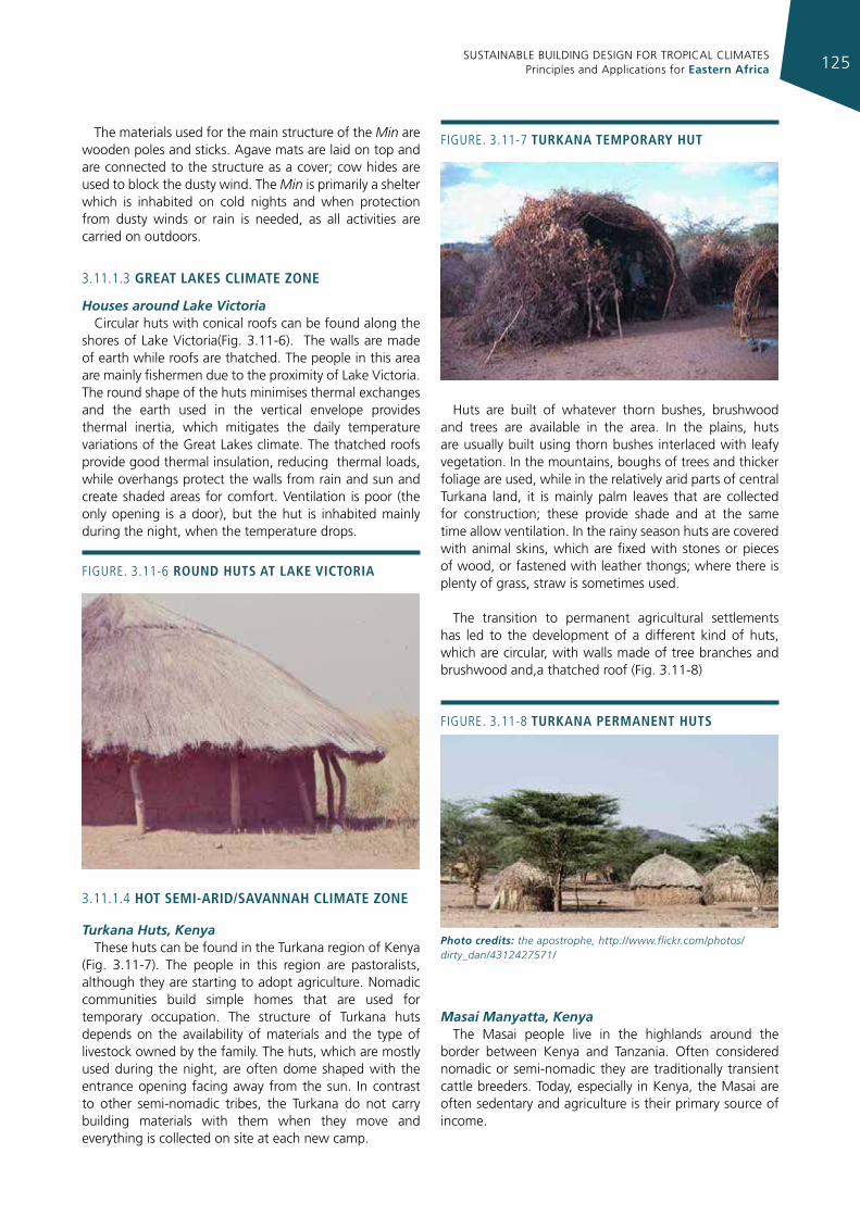
SUSTAINABLE BUILDING DESIGN FOR TROPICAL CLIMATES Principles and Applications for Eastern Africa 125
The materials used for the main structure of the Min are wooden poles and sticks. Agave mats are laid on top and are connected to the structure as a cover; cow hides are used to block the dusty wind. The Min is primarily a shelter which is inhabited on cold nights and when protection from dusty winds or rain is needed, as all activities are carried on outdoors.
3.11.1.3 great lakes clImate zone
Houses around Lake VictoriaCircular huts with conical roofs can be found along the
shores of Lake Victoria(Fig. 3.11-6). The walls are made of earth while roofs are thatched. The people in this area are mainly fishermen due to the proximity of Lake Victoria. The round shape of the huts minimises thermal exchanges and the earth used in the vertical envelope provides thermal inertia, which mitigates the daily temperature variations of the Great Lakes climate. The thatched roofs provide good thermal insulation, reducing thermal loads, while overhangs protect the walls from rain and sun and create shaded areas for comfort. Ventilation is poor (the only opening is a door), but the hut is inhabited mainly during the night, when the temperature drops.
3.11.1.4 hot semI-arId/savannah clImate zone
Turkana Huts, KenyaThese huts can be found in the Turkana region of Kenya
(Fig. 3.11-7). The people in this region are pastoralists, although they are starting to adopt agriculture. Nomadic communities build simple homes that are used for temporary occupation. The structure of Turkana huts depends on the availability of materials and the type of livestock owned by the family. The huts, which are mostly used during the night, are often dome shaped with the entrance opening facing away from the sun. In contrast to other semi-nomadic tribes, the Turkana do not carry building materials with them when they move and everything is collected on site at each new camp.
Huts are built of whatever thorn bushes, brushwood and trees are available in the area. In the plains, huts are usually built using thorn bushes interlaced with leafy vegetation. In the mountains, boughs of trees and thicker foliage are used, while in the relatively arid parts of central Turkana land, it is mainly palm leaves that are collected for construction; these provide shade and at the same time allow ventilation. In the rainy season huts are covered with animal skins, which are fixed with stones or pieces of wood, or fastened with leather thongs; where there is plenty of grass, straw is sometimes used.
The transition to permanent agricultural settlements has led to the development of a different kind of huts, which are circular, with walls made of tree branches and brushwood and,a thatched roof (Fig. 3.11-8)
Masai Manyatta, KenyaThe Masai people live in the highlands around the
border between Kenya and Tanzania. Often considered nomadic or semi-nomadic they are traditionally transient cattle breeders. Today, especially in Kenya, the Masai are often sedentary and agriculture is their primary source of income.
Figure. 3.11-6 round huts at lake vIctorIa
Figure. 3.11-7 turkana temporary hut
Figure. 3.11-8 turkana permanent huts
Photo credits: the apostrophe, http://www.flickr.com/photos/dirty_dan/4312427571/
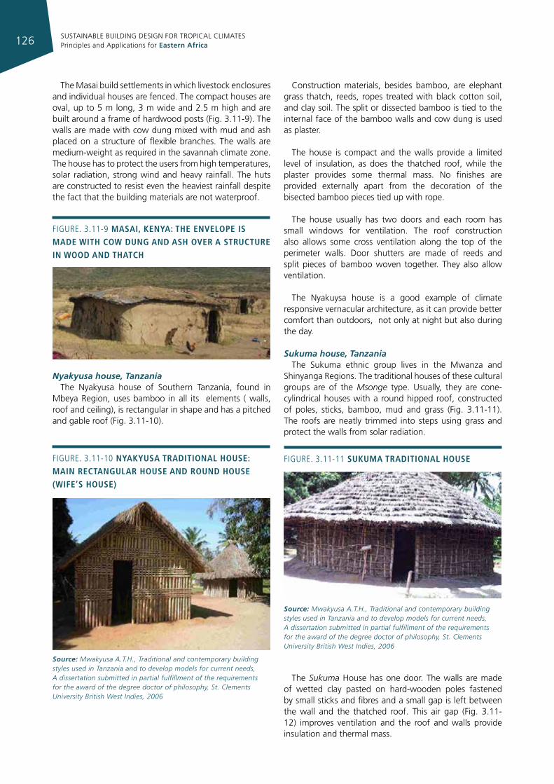
SUSTAINABLE BUILDING DESIGN FOR TROPICAL CLIMATES Principles and Applications for Eastern Africa126
The Masai build settlements in which livestock enclosures and individual houses are fenced. The compact houses are oval, up to 5 m long, 3 m wide and 2.5 m high and are built around a frame of hardwood posts (Fig. 3.11-9). The walls are made with cow dung mixed with mud and ash placed on a structure of flexible branches. The walls are medium-weight as required in the savannah climate zone. The house has to protect the users from high temperatures, solar radiation, strong wind and heavy rainfall. The huts are constructed to resist even the heaviest rainfall despite the fact that the building materials are not waterproof.
Nyakyusa house, TanzaniaThe Nyakyusa house of Southern Tanzania, found in
Mbeya Region, uses bamboo in all its elements ( walls, roof and ceiling), is rectangular in shape and has a pitched and gable roof (Fig. 3.11-10).
Construction materials, besides bamboo, are elephant grass thatch, reeds, ropes treated with black cotton soil, and clay soil. The split or dissected bamboo is tied to the internal face of the bamboo walls and cow dung is used as plaster.
The house is compact and the walls provide a limited level of insulation, as does the thatched roof, while the plaster provides some thermal mass. No finishes are provided externally apart from the decoration of the bisected bamboo pieces tied up with rope.
The house usually has two doors and each room has small windows for ventilation. The roof construction also allows some cross ventilation along the top of the perimeter walls. Door shutters are made of reeds and split pieces of bamboo woven together. They also allow ventilation.
The Nyakuysa house is a good example of climate responsive vernacular architecture, as it can provide better comfort than outdoors, not only at night but also during the day.
Sukuma house, TanzaniaThe Sukuma ethnic group lives in the Mwanza and
Shinyanga Regions. The traditional houses of these cultural groups are of the Msonge type. Usually, they are cone-cylindrical houses with a round hipped roof, constructed of poles, sticks, bamboo, mud and grass (Fig. 3.11-11). The roofs are neatly trimmed into steps using grass and protect the walls from solar radiation.
The Sukuma House has one door. The walls are made of wetted clay pasted on hard-wooden poles fastened by small sticks and fibres and a small gap is left between the wall and the thatched roof. This air gap (Fig. 3.11-12) improves ventilation and the roof and walls provide insulation and thermal mass.
Figure. 3.11-9 masaI, kenya: the envelope Is made WIth coW dung and ash over a structure In Wood and thatch
Figure. 3.11-10 nyakyusa tradItIonal house: maIn rectangular house and round house (WIfe’s house)
Source: Mwakyusa A.T.H., Traditional and contemporary building styles used in Tanzania and to develop models for current needs, A dissertation submitted in partial fulfillment of the requirements for the award of the degree doctor of philosophy, St. Clements University British West Indies, 2006
Figure. 3.11-11 sukuma tradItIonal house
Source: Mwakyusa A.T.H., Traditional and contemporary building styles used in Tanzania and to develop models for current needs, A dissertation submitted in partial fulfillment of the requirements for the award of the degree doctor of philosophy, St. Clements University British West Indies, 2006
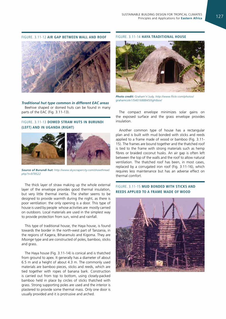
SUSTAINABLE BUILDING DESIGN FOR TROPICAL CLIMATES Principles and Applications for Eastern Africa 127
Traditional hut type common in different EAC areasBeehive shaped or domed huts can be found in many
parts of the EAC (Fig. 3.11-13).
The thick layer of straw making up the whole external layer of the envelope provides good thermal insulation, but very little thermal inertia. The shelter seems to be designed to provide warmth during the night, as there is poor ventilation: the only opening is a door. This type of house is used by people whose activities are mostly carried on outdoors. Local materials are used in the simplest way to provide protection from sun, wind and rainfall.
This type of traditional house, the Haya house, is found towards the border in the north-west part of Tanzania, in the regions of Kagera, Biharamulo and Kigoma. They are Msonge type and are constructed of poles, bamboo, sticks and grass.
The Haya house (Fig. 3.11-14) is conical and is thatched from ground to apex. It generally has a diameter of about 6.5 m and a height of about 4.3 m. The commonly used materials are bamboo pieces, sticks and reeds, which are tied together with ropes of banana bark. Construction is carried out from top to bottom, using closely-packed bamboo held in place by circles of sticks thatched with grass. Strong supporting poles are used and the interior is plastered to provide some thermal mass. Only one door is usually provided and it is protrusive and arched.
The compact envelope minimizes solar gains on the exposed surface and the grass envelope provides insulation.
Another common type of house has a rectangular plan and is built with mud bonded with sticks and reeds applied to a frame made of wood or bamboo (Fig. 3.11-15). The frames are bound together and the thatched roof is tied to the frame with strong materials such as hemp fibres or braided coconut husks. An air gap is often left between the top of the walls and the roof to allow natural ventilation. The thatched roof has been, in most cases, replaced by a corrugated iron roof (Fig. 3.11-16), which requires less maintenance but has an adverse effect on thermal comfort.
Figure. 3.11-12 aIr gap betWeen Wall and roof
Figure. 3.11-13 domed straW huts In burundI (left) and In uganda (rIght)
Source of Burundi hut: http://www.skyscrapercity.com/showthread.php?t=978522
Figure. 3.11-14 haya tradItIonal house
Photo credit: Graham’n’Judy, http://www.flickr.com/photos/grahamcole1/5401688845/lightbox/
Figure. 3.11-15 mud bonded WIth stIcks and reeds applIed to a frame made of Wood
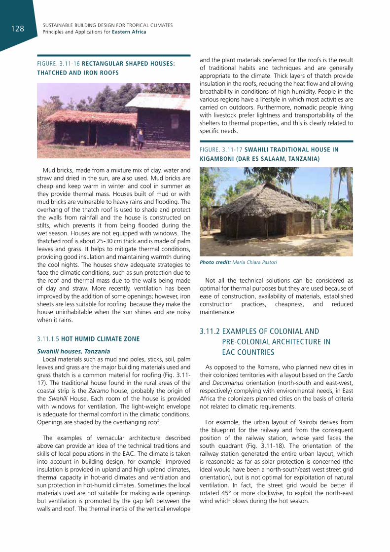
SUSTAINABLE BUILDING DESIGN FOR TROPICAL CLIMATES Principles and Applications for Eastern Africa128
Mud bricks, made from a mixture mix of clay, water and straw and dried in the sun, are also used. Mud bricks are cheap and keep warm in winter and cool in summer as they provide thermal mass. Houses built of mud or with mud bricks are vulnerable to heavy rains and flooding. The overhang of the thatch roof is used to shade and protect the walls from rainfall and the house is constructed on stilts, which prevents it from being flooded during the wet season. Houses are not equipped with windows. The thatched roof is about 25-30 cm thick and is made of palm leaves and grass. It helps to mitigate thermal conditions, providing good insulation and maintaining warmth during the cool nights. The houses show adequate strategies to face the climatic conditions, such as sun protection due to the roof and thermal mass due to the walls being made of clay and straw. More recently, ventilation has been improved by the addition of some openings; however, iron sheets are less suitable for roofing because they make the house uninhabitable when the sun shines and are noisy when it rains.
3.11.1.5 hot humId clImate zone
Swahili houses, TanzaniaLocal materials such as mud and poles, sticks, soil, palm
leaves and grass are the major building materials used and grass thatch is a common material for roofing (Fig. 3.11-17). The traditional house found in the rural areas of the coastal strip is the Zaramo house, probably the origin of the Swahili House. Each room of the house is provided with windows for ventilation. The light-weight envelope is adequate for thermal comfort in the climatic conditions. Openings are shaded by the overhanging roof.
The examples of vernacular architecture described above can provide an idea of the technical traditions and skills of local populations in the EAC. The climate is taken into account in building design, for example improved insulation is provided in upland and high upland climates, thermal capacity in hot-arid climates and ventilation and sun protection in hot-humid climates. Sometimes the local materials used are not suitable for making wide openings but ventilation is promoted by the gap left between the walls and roof. The thermal inertia of the vertical envelope
and the plant materials preferred for the roofs is the result of traditional habits and techniques and are generally appropriate to the climate. Thick layers of thatch provide insulation in the roofs, reducing the heat flow and allowing breathability in conditions of high humidity. People in the various regions have a lifestyle in which most activities are carried on outdoors. Furthermore, nomadic people living with livestock prefer lightness and transportability of the shelters to thermal properties, and this is clearly related to specific needs.
Not all the technical solutions can be considered as optimal for thermal purposes but they are used because of ease of construction, availability of materials, established construction practices, cheapness, and reduced maintenance.
3.11.2 examples of colonIal and pre-colonIal archITecTure In eac counTrIes
As opposed to the Romans, who planned new cities in their colonized territories with a layout based on the Cardo and Decumanus orientation (north-south and east-west, respectively) complying with environmental needs, in East Africa the colonizers planned cities on the basis of criteria not related to climatic requirements.
For example, the urban layout of Nairobi derives from the blueprint for the railway and from the consequent position of the railway station, whose yard faces the south quadrant (Fig. 3.11-18). The orientation of the railway station generated the entire urban layout, which is reasonable as far as solar protection is concerned (the ideal would have been a north-south/east west street grid orientation), but is not optimal for exploitation of natural ventilation. In fact, the street grid would be better if rotated 45° or more clockwise, to exploit the north-east wind which blows during the hot season.
Figure. 3.11-17 sWahIlI tradItIonal house In kIgambonI (dar es salaam, tanzanIa)
Photo credit: Maria Chiara Pastori
Figure. 3.11-16 rectangular shaped houses: thatched and Iron roofs
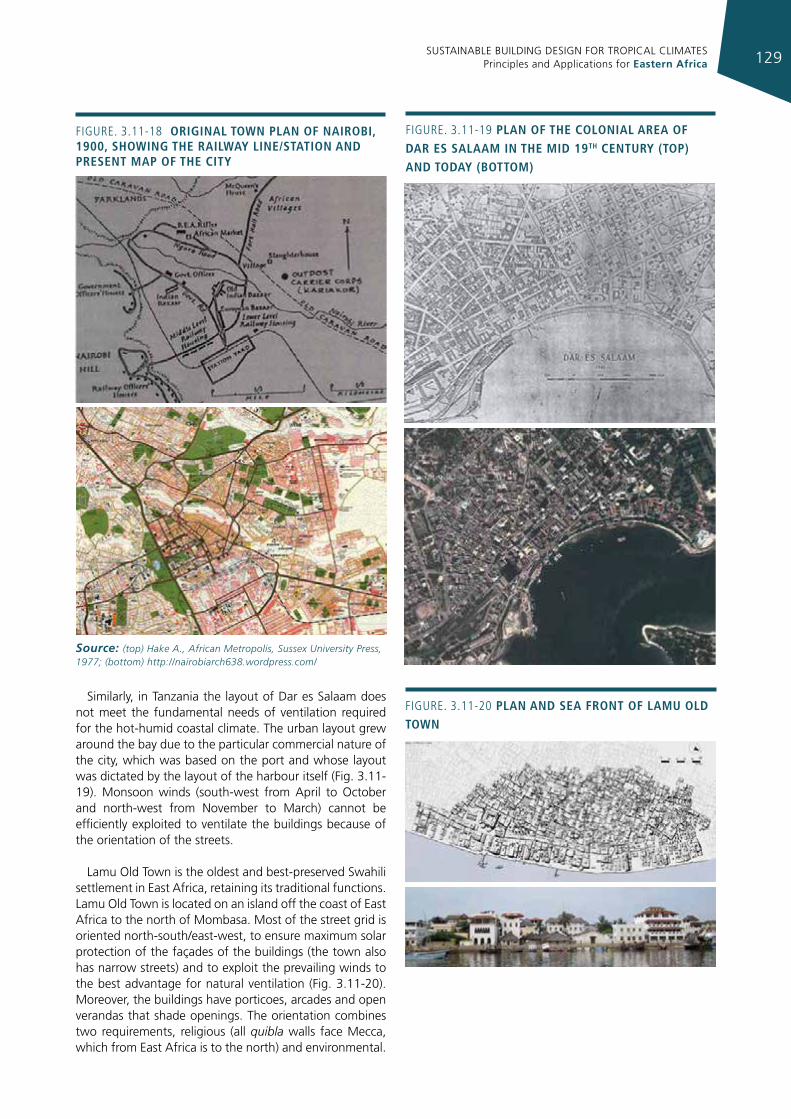
SUSTAINABLE BUILDING DESIGN FOR TROPICAL CLIMATES Principles and Applications for Eastern Africa 129
Similarly, in Tanzania the layout of Dar es Salaam does not meet the fundamental needs of ventilation required for the hot-humid coastal climate. The urban layout grew around the bay due to the particular commercial nature of the city, which was based on the port and whose layout was dictated by the layout of the harbour itself (Fig. 3.11-19). Monsoon winds (south-west from April to October and north-west from November to March) cannot be efficiently exploited to ventilate the buildings because of the orientation of the streets.
Lamu Old Town is the oldest and best-preserved Swahili settlement in East Africa, retaining its traditional functions. Lamu Old Town is located on an island off the coast of East Africa to the north of Mombasa. Most of the street grid is oriented north-south/east-west, to ensure maximum solar protection of the façades of the buildings (the town also has narrow streets) and to exploit the prevailing winds to the best advantage for natural ventilation (Fig. 3.11-20). Moreover, the buildings have porticoes, arcades and open verandas that shade openings. The orientation combines two requirements, religious (all quibla walls face Mecca, which from East Africa is to the north) and environmental.
Figure. 3.11-18 orIgInal toWn plan of naIrobI, 1900, shoWIng the raIlWay lIne/statIon and present map of the cIty
Source: (top) Hake A., African Metropolis, Sussex University Press, 1977; (bottom) http://nairobiarch638.wordpress.com/
Figure. 3.11-19 plan of the colonIal area of dar es salaam In the mId 19th century (top) and today (bottom)
Figure. 3.11-20 plan and sea front of lamu old toWn
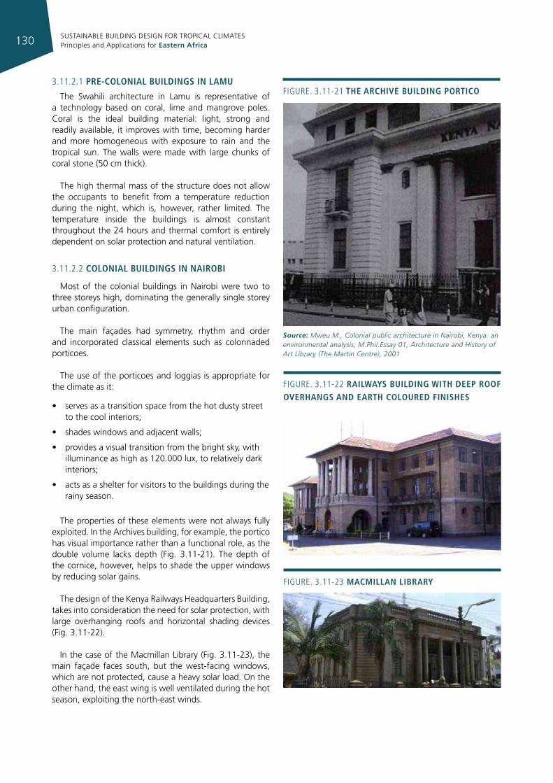
SUSTAINABLE BUILDING DESIGN FOR TROPICAL CLIMATES Principles and Applications for Eastern Africa130
3.11.2.1 pre-colonIal buIldIngs In lamu
The Swahili architecture in Lamu is representative of a technology based on coral, lime and mangrove poles. Coral is the ideal building material: light, strong and readily available, it improves with time, becoming harder and more homogeneous with exposure to rain and the tropical sun. The walls were made with large chunks of coral stone (50 cm thick).
The high thermal mass of the structure does not allow the occupants to benefit from a temperature reduction during the night, which is, however, rather limited. The temperature inside the buildings is almost constant throughout the 24 hours and thermal comfort is entirely dependent on solar protection and natural ventilation.
3.11.2.2 colonIal buIldIngs In naIrobI
Most of the colonial buildings in Nairobi were two to three storeys high, dominating the generally single storey urban configuration.
The main façades had symmetry, rhythm and order and incorporated classical elements such as colonnaded porticoes.
The use of the porticoes and loggias is appropriate for the climate as it:
• serves as a transition space from the hot dusty street to the cool interiors;
• shades windows and adjacent walls;
• provides a visual transition from the bright sky, with illuminance as high as 120.000 lux, to relatively dark interiors;
• acts as a shelter for visitors to the buildings during the rainy season.
The properties of these elements were not always fully exploited. In the Archives building, for example, the portico has visual importance rather than a functional role, as the double volume lacks depth (Fig. 3.11-21). The depth of the cornice, however, helps to shade the upper windows by reducing solar gains.
The design of the Kenya Railways Headquarters Building, takes into consideration the need for solar protection, with large overhanging roofs and horizontal shading devices (Fig. 3.11-22).
In the case of the Macmillan Library (Fig. 3.11-23), the main façade faces south, but the west-facing windows, which are not protected, cause a heavy solar load. On the other hand, the east wing is well ventilated during the hot season, exploiting the north-east winds.
Figure. 3.11-21 the archIve buIldIng portIco
Source: Mweu M., Colonial public architecture in Nairobi, Kenya: an environmental analysis, M.Phil.Essay 01, Architecture and History of Art Library (The Martin Centre), 2001
Figure. 3.11-22 raIlWays buIldIng WIth deep roof overhangs and earth coloured fInIshes
Figure. 3.11-23 macmIllan lIbrary
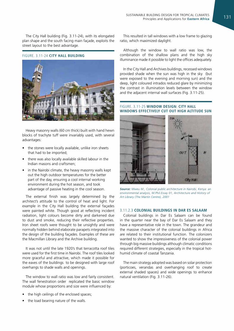
SUSTAINABLE BUILDING DESIGN FOR TROPICAL CLIMATES Principles and Applications for Eastern Africa 131
The City Hall building (Fig. 3.11-24), with its elongated plan shape and the south facing main façade, exploits the street layout to the best advantage.
Heavy masonry walls (60 cm thick) built with hand hewn blocks of trachyte tuff were invariably used, with several advantages:
• the stones were locally available, unlike iron sheets that had to be imported;
• there was also locally available skilled labour in the Indian masons and craftsmen;
• in the Nairobi climate, the heavy masonry walls kept out the high outdoor temperatures for the better part of the day, ensuring a cool internal working environment during the hot season, and took advantage of passive heating in the cool season.
The external finish was largely determined by the architect’s attitude to the control of heat and light. For example in the City Hall building the external façades were painted white. Though good at reflecting incident radiation, light colours become dirty and darkened due to dust and smoke, reducing their reflective properties. Iron sheet roofs were thought to be unsightly and were normally hidden behind elaborate parapets integrated into the design of the building façades. Examples of these are the Macmillan Library and the Archive building.
It was not until the late 1920’s that terracotta roof tiles were used for the first time in Nairobi. The roof tiles looked more graceful and attractive, which made it possible for the eaves of the buildings to be designed with large roof overhangs to shade walls and openings.
The window to wall ratio was low and fairly consistent. The wall fenestration order replicated the basic window module whose proportions and size were influenced by:
• the high ceilings of the enclosed spaces;
• the load bearing nature of the walls.
This resulted in tall windows with a low frame to glazing ratio, which maximized daylight.
Although the window to wall ratio was low, the combination of the shallow plans and the high sky illuminance made it possible to light the offices adequately.
In the City Hall and Archives buildings, recessed windows provided shade when the sun was high in the sky (but were exposed to the evening and morning sun) and the deep, light coloured intrados reduced glare by minimizing the contrast in illumination levels between the window and the adjacent internal wall surfaces (Fig. 3.11-25).
3.11.2.3 colonIal buIldIngs In dar es salaamColonial buildings in Dar Es Salaam can be found
in the quarter near the bay of Dar Es Salaam and they have a representative role in the town. The grandeur and the massive character of the colonial buildings in Africa are related to their institutional function. The colonizers wanted to show the impressiveness of the colonial power through big massive buildings although climatic conditions required different strategies, especially in the tropical hot-humid climate of coastal Tanzania.
The main strategy adopted was based on solar protection (porticoes, verandas and overhanging roof to create external shaded spaces) and wide openings to enhance natural ventilation (Fig. 3.11-26).
Figure. 3.11-24 cIty hall buIldIng
Figure. 3.11-25 WIndoW desIgn: cIty hall WIndoWs effectIvely cut out hIgh altItude sun
Source: Mweu M., Colonial public architecture in Nairobi, Kenya: an environmental analysis, M.Phil.Essay 01, Architecture and History of Art Library (The Martin Centre), 2001
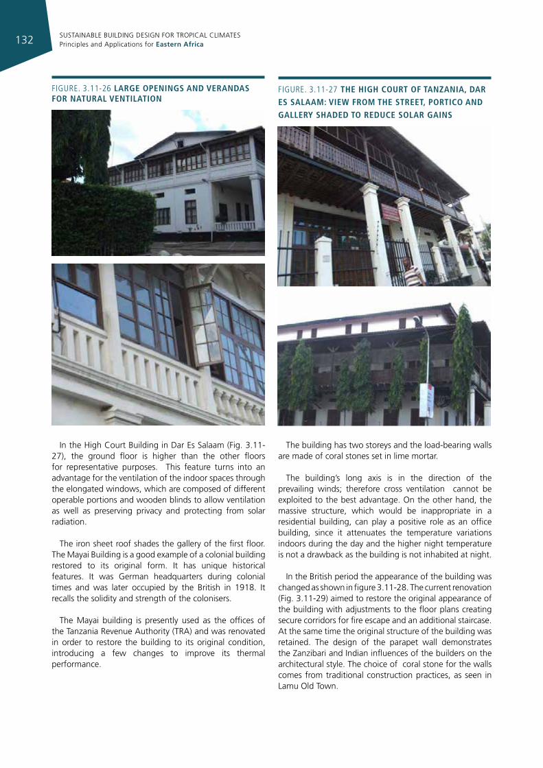
SUSTAINABLE BUILDING DESIGN FOR TROPICAL CLIMATES Principles and Applications for Eastern Africa132
In the High Court Building in Dar Es Salaam (Fig. 3.11-27), the ground floor is higher than the other floors for representative purposes. This feature turns into an advantage for the ventilation of the indoor spaces through the elongated windows, which are composed of different operable portions and wooden blinds to allow ventilation as well as preserving privacy and protecting from solar radiation.
The iron sheet roof shades the gallery of the first floor. The Mayai Building is a good example of a colonial building restored to its original form. It has unique historical features. It was German headquarters during colonial times and was later occupied by the British in 1918. It recalls the solidity and strength of the colonisers.
The Mayai building is presently used as the offices of the Tanzania Revenue Authority (TRA) and was renovated in order to restore the building to its original condition, introducing a few changes to improve its thermal performance.
The building has two storeys and the load-bearing walls are made of coral stones set in lime mortar.
The building’s long axis is in the direction of the prevailing winds; therefore cross ventilation cannot be exploited to the best advantage. On the other hand, the massive structure, which would be inappropriate in a residential building, can play a positive role as an office building, since it attenuates the temperature variations indoors during the day and the higher night temperature is not a drawback as the building is not inhabited at night.
In the British period the appearance of the building was changed as shown in figure 3.11-28. The current renovation (Fig. 3.11-29) aimed to restore the original appearance of the building with adjustments to the floor plans creating secure corridors for fire escape and an additional staircase. At the same time the original structure of the building was retained. The design of the parapet wall demonstrates the Zanzibari and Indian influences of the builders on the architectural style. The choice of coral stone for the walls comes from traditional construction practices, as seen in Lamu Old Town.
Figure. 3.11-26 large openIngs and verandas for natural ventIlatIon
Figure. 3.11-27 the hIgh court of tanzanIa, dar es salaam: vIeW from the street, portIco and gallery shaded to reduce solar gaIns
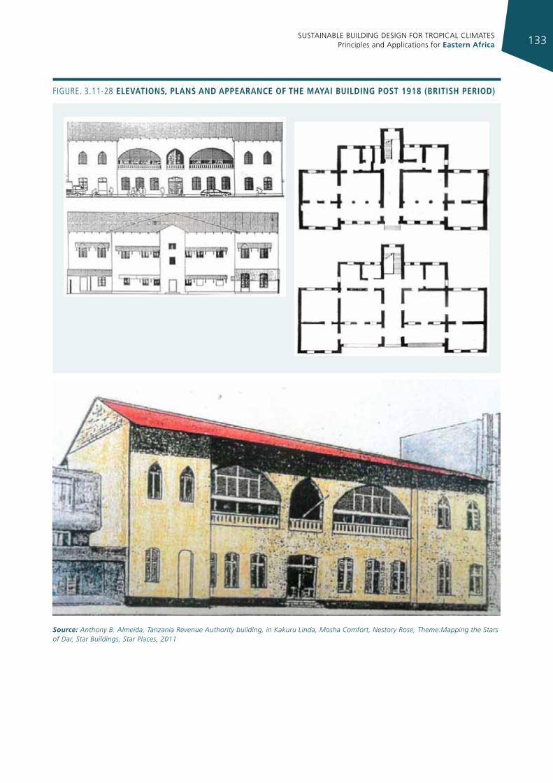
SUSTAINABLE BUILDING DESIGN FOR TROPICAL CLIMATES Principles and Applications for Eastern Africa 133
Figure. 3.11-28 elevatIons, plans and appearance of the mayaI buIldIng post 1918 (brItIsh perIod)
Source: Anthony B. Almeida, Tanzania Revenue Authority building, in Kakuru Linda, Mosha Comfort, Nestory Rose, Theme:Mapping the Stars of Dar, Star Buildings, Star Places, 2011
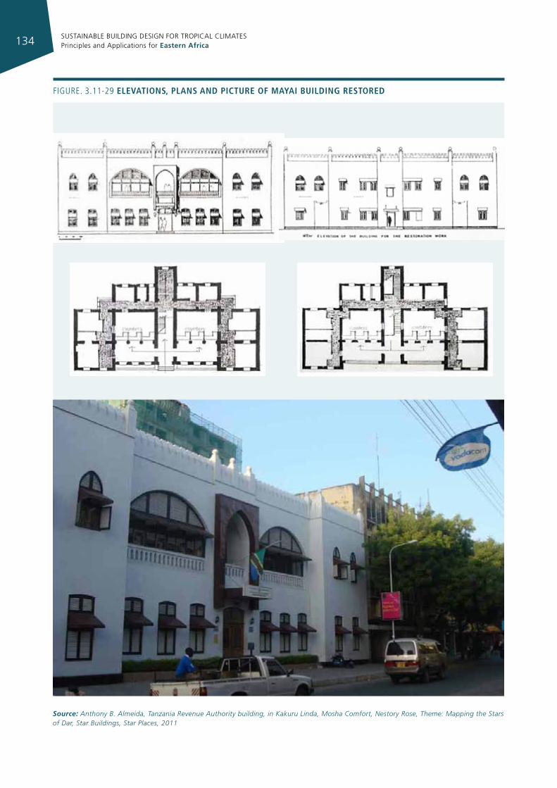
SUSTAINABLE BUILDING DESIGN FOR TROPICAL CLIMATES Principles and Applications for Eastern Africa134
Figure. 3.11-29 elevatIons, plans and pIcture of mayaI buIldIng restored
Source: Anthony B. Almeida, Tanzania Revenue Authority building, in Kakuru Linda, Mosha Comfort, Nestory Rose, Theme: Mapping the Stars of Dar, Star Buildings, Star Places, 2011
SUSTAINABLE BUILDING DESIGN FOR TROPICAL CLIMATES Principles and Applications for Eastern Africa 135
The building had compact plans in which corridors were created and the roof was restored to its original morphology.
The restored building has new shading devices at all the windows to control direct sun radiation. This is also provided by the shutters, which are used to darken the interior spaces without compromising ventilation. The entrance is designed to match the building elevations.
3.11.2.4 evolutIon of colonIal archItecture
Buildings constructed in the first colonial period were a reproduction of occidental architecture. To deal with the obvious inadequacies related to climate, substantial changes were then introduced Particular adaptations can be recognized in:
• widening of the windows to improve natural ventilation;
• double facing rooms (north/south) to adapt to the solar path in near equatorial latitudes and to favour cross ventilation;
• covered porches frequently used around the buildings to provide shading;
• buildings on studs, to avoid rising damp in the humid climate.
All these innovations were introduced in order to adapt the buildings to the tropical climate by protecting them from intense radiation and heavy rains, facilitating natural ventilation and reducing the high rate of humidity and moisture coming into the building from the ground.
SUSTAINABLE BUILDING DESIGN FOR TROPICAL CLIMATES Principles and Applications for Eastern Africa136
energy effIcIenT buIldIngs desIgn
04
4.1 The envelope
There are, for some types of building, periods of the year and climate zones in which thermal comfort cannot be achieved without the use of a cooling or heating system even if the building has been designed according to the guidelines given in chapter 3. This is common in commercial buildings, because of the significant internal loads (people, office equipment, artificial lighting), but – to a lesser extent – it also applies to residential buildings. To cope with these situations, in which a mechanical system is needed to provide comfortable conditions, openings must be designed with special care in order to minimise energy consumption. The reason for this is that openings are glazed and windows are shut during the period in which the cooling system is working, with the following consequences:
• solar gains are a more critical issue because of the greenhouse effect;
• natural lighting is a more critical issue, especially in commercial buildings, because of the impact of glare on occupants, who cannot freely choose the position of their workstation and because the visual quality of the environment can be influenced by the type of glazing used;
• thermal comfort is affected by the temperature reached by the glazed surfaces (even if solar protections are provided, diffuse radiation causes an increase in the temperature of the glass).
4.1.1 glaZIng
Glass panes were perhaps the most important technological advance in the history of buildings. They allowed an extraordinary leap forward in the quality of indoor life, making other innovations possible. No longer was there the forced conjunction of light and outside air (cold in winter and hot in summer), which had to pass through the same openings (in fact the word window in English is derived from the Icelandic word meaning “eye of the wind”). And not just light without “wind”; the sun penetrating through the glass also heats the room, thanks to the greenhouse effect. Of course this is a problem in
summer, but it is easily solved with external protection and/or by opening the windows.
4.1.1.1 glass, clImate and energy
Glazed windows have evolved in such a way as to provide systems which can be adapted to external and internal conditions, according to different climates. In central and northern Europe relatively large glass surfaces are found. They are partially operable (typically the sash window) and have internal sunscreens (curtains), which are often dark. Quite different solutions have evolved in the Mediterranean: glass surfaces are smaller than those in central and northern Europe, windows open fully for greater benefit from natural ventilation in summer, and there is external sun protection (usually in the form of shutters, often with movable slats). This is completely logical: where it is cold in winter, the sky is mostly cloudy and the summers are short and cool, you have to let the sun in as much as possible, sunscreens should serve only to adjust the intensity of the entering light and ventilation should not be excessive because the air is cool. In the Mediterranean, it is a different story: sun protection and ventilation are the prerequisites for a comfortable environment in summer, but in winter ventilation must be limited and some solar gain is welcome.
In hot-humid tropical climates the jalousie window has been the most popular and appropriate technological solution for the fine tuning of natural ventilation.
Up until the nineteenth century these logical solutions were adopted in all types of building, residential or commercial, with few exceptions. Then, at the beginning of the twentieth century a revolutionary tsunami hit architecture, a revolution which made a clean sweep of all the rules of the past by imposing a new slogan: lightness and transparency, which translated into an envelope made of glass .
So, in the midst of brilliant insights, the abuse of glass developed and was consolidated, leading, inevitably, to the abandonment of (often to contempt for) the principle of adaptation to climate, and buildings - glittering jewels - became the same everywhere, from Oslo to Dubai.
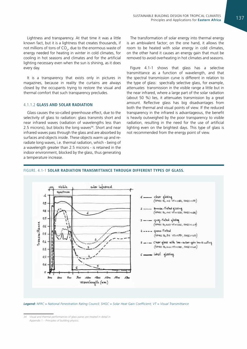
SUSTAINABLE BUILDING DESIGN FOR TROPICAL CLIMATES Principles and Applications for Eastern Africa 137
Lightness and transparency. At that time it was a little known fact, but it is a lightness that creates thousands, if not millions of tons of CO2, due to the enormous waste of energy needed for heating in winter in cold climates, for cooling in hot seasons and climates and for the artificial lighting necessary even when the sun is shining, as it does every day.
It is a transparency that exists only in pictures in magazines, because in reality the curtains are always closed by the occupants trying to restore the visual and thermal comfort that such transparency precludes.
4.1.1.2 glass and solar radIatIon
Glass causes the so-called greenhouse effect, due to the selectivity of glass to radiation: glass transmits short and near infrared waves (radiation of wavelengths less than 2.5 microns), but blocks the long waves34. Short and near infrared waves pass through the glass and are absorbed by surfaces and objects inside. These objects warm up and re-radiate long waves, i.e. thermal radiation, which - being of a wavelength greater than 2.5 microns - is retained in the indoor environment, blocked by the glass, thus generating a temperature increase.
34 Visual and thermal performances of glass panes are treated in detail in Appendix 1 – Principles of building physics.
The transformation of solar energy into thermal energy is an ambivalent factor; on the one hand, it allows the room to be heated with solar energy in cold climates, on the other hand it causes an energy gain that must be removed to avoid overheating in hot climates and seasons.
Figure 4.1-1 shows that glass has a selective transmittance as a function of wavelength, and that the spectral transmission curve is different in relation to the type of glass: spectrally selective glass, for example, attenuates transmission in the visible range a little but in the near infrared, where a large part of the solar radiation (about 50 %) lies, it attenuates transmission by a great amount. Reflective glass has big disadvantages from both the thermal and visual points of view. If the reduced transparency in the infrared is advantageous, the benefit is heavily outweighed by the poor transparency to visible radiation, resulting in the need for the use of artificial lighting even on the brightest days. This type of glass is not recommended from the energy point of view.
Figure. 4.1-1 solar radIatIon transmIttance through dIfferent types of glass.
Legend: NFRC = National Fenestration Rating Council; SHGC = Solar Heat Gain Coefficient; VT = Visual Transmittance
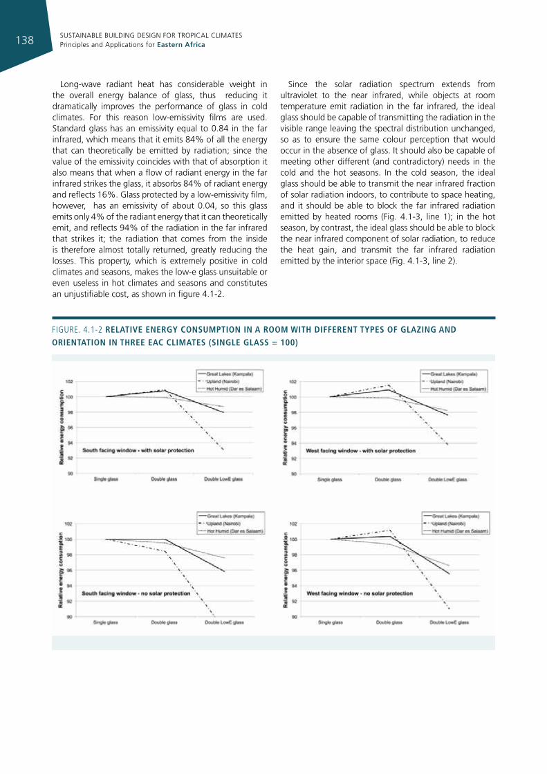
SUSTAINABLE BUILDING DESIGN FOR TROPICAL CLIMATES Principles and Applications for Eastern Africa138
Long-wave radiant heat has considerable weight in the overall energy balance of glass, thus reducing it dramatically improves the performance of glass in cold climates. For this reason low-emissivity films are used. Standard glass has an emissivity equal to 0.84 in the far infrared, which means that it emits 84% of all the energy that can theoretically be emitted by radiation; since the value of the emissivity coincides with that of absorption it also means that when a flow of radiant energy in the far infrared strikes the glass, it absorbs 84% of radiant energy and reflects 16%. Glass protected by a low-emissivity film, however, has an emissivity of about 0.04, so this glass emits only 4% of the radiant energy that it can theoretically emit, and reflects 94% of the radiation in the far infrared that strikes it; the radiation that comes from the inside is therefore almost totally returned, greatly reducing the losses. This property, which is extremely positive in cold climates and seasons, makes the low-e glass unsuitable or even useless in hot climates and seasons and constitutes an unjustifiable cost, as shown in figure 4.1-2.
Since the solar radiation spectrum extends from ultraviolet to the near infrared, while objects at room temperature emit radiation in the far infrared, the ideal glass should be capable of transmitting the radiation in the visible range leaving the spectral distribution unchanged, so as to ensure the same colour perception that would occur in the absence of glass. It should also be capable of meeting other different (and contradictory) needs in the cold and the hot seasons. In the cold season, the ideal glass should be able to transmit the near infrared fraction of solar radiation indoors, to contribute to space heating, and it should be able to block the far infrared radiation emitted by heated rooms (Fig. 4.1-3, line 1); in the hot season, by contrast, the ideal glass should be able to block the near infrared component of solar radiation, to reduce the heat gain, and transmit the far infrared radiation emitted by the interior space (Fig. 4.1-3, line 2).
Figure. 4.1-2 relatIve energy consumptIon In a room WIth dIfferent types of glazIng and orIentatIon In three eac clImates (sIngle glass = 100)
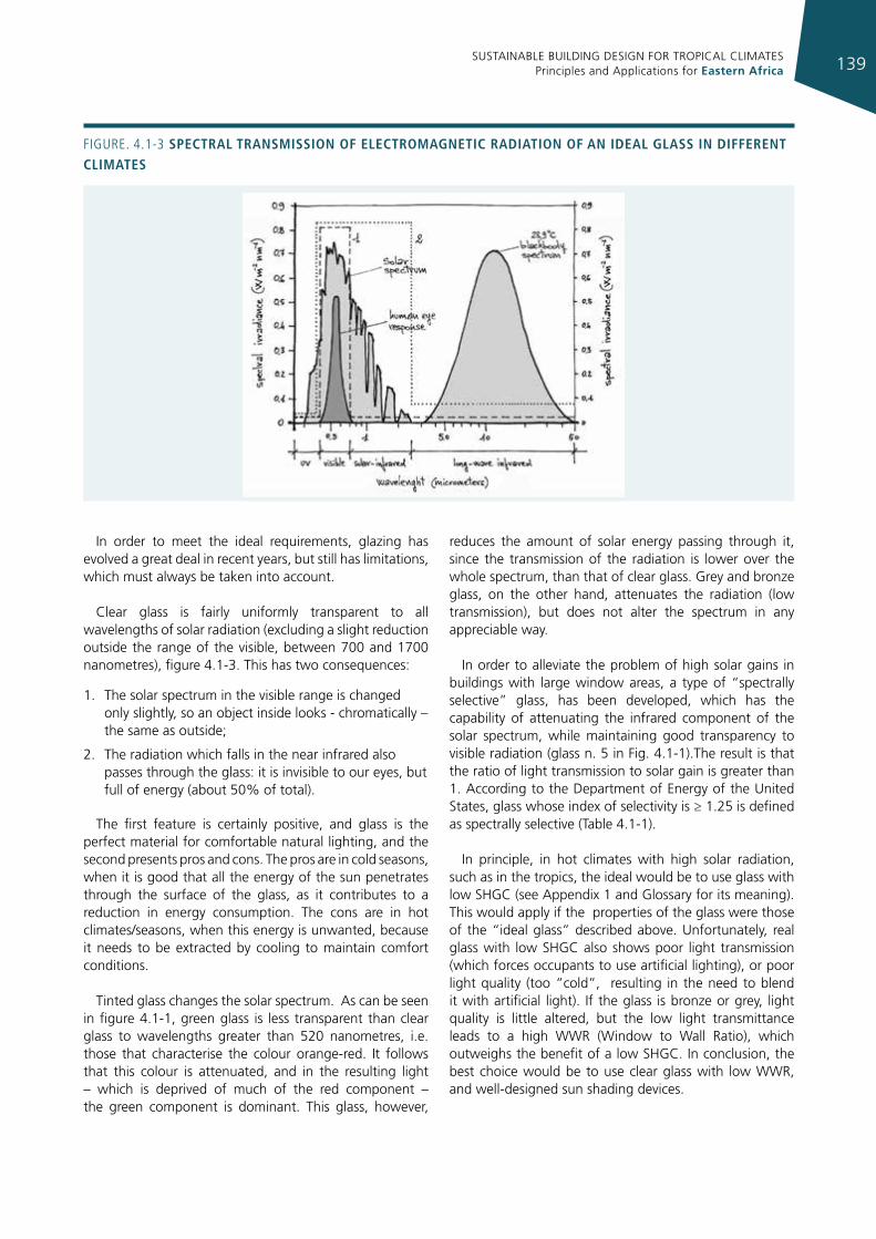
SUSTAINABLE BUILDING DESIGN FOR TROPICAL CLIMATES Principles and Applications for Eastern Africa 139
In order to meet the ideal requirements, glazing has evolved a great deal in recent years, but still has limitations, which must always be taken into account.
Clear glass is fairly uniformly transparent to all wavelengths of solar radiation (excluding a slight reduction outside the range of the visible, between 700 and 1700 nanometres), figure 4.1-3. This has two consequences:
1. The solar spectrum in the visible range is changed only slightly, so an object inside looks - chromatically – the same as outside;
2. The radiation which falls in the near infrared also passes through the glass: it is invisible to our eyes, but full of energy (about 50% of total).
The first feature is certainly positive, and glass is the perfect material for comfortable natural lighting, and the second presents pros and cons. The pros are in cold seasons, when it is good that all the energy of the sun penetrates through the surface of the glass, as it contributes to a reduction in energy consumption. The cons are in hot climates/seasons, when this energy is unwanted, because it needs to be extracted by cooling to maintain comfort conditions.
Tinted glass changes the solar spectrum. As can be seen in figure 4.1-1, green glass is less transparent than clear glass to wavelengths greater than 520 nanometres, i.e. those that characterise the colour orange-red. It follows that this colour is attenuated, and in the resulting light – which is deprived of much of the red component – the green component is dominant. This glass, however,
reduces the amount of solar energy passing through it, since the transmission of the radiation is lower over the whole spectrum, than that of clear glass. Grey and bronze glass, on the other hand, attenuates the radiation (low transmission), but does not alter the spectrum in any appreciable way.
In order to alleviate the problem of high solar gains in buildings with large window areas, a type of “spectrally selective” glass, has been developed, which has the capability of attenuating the infrared component of the solar spectrum, while maintaining good transparency to visible radiation (glass n. 5 in Fig. 4.1-1).The result is that the ratio of light transmission to solar gain is greater than 1. According to the Department of Energy of the United States, glass whose index of selectivity is ≥ 1.25 is defined as spectrally selective (Table 4.1-1).
In principle, in hot climates with high solar radiation, such as in the tropics, the ideal would be to use glass with low SHGC (see Appendix 1 and Glossary for its meaning). This would apply if the properties of the glass were those of the “ideal glass” described above. Unfortunately, real glass with low SHGC also shows poor light transmission (which forces occupants to use artificial lighting), or poor light quality (too “cold”, resulting in the need to blend it with artificial light). If the glass is bronze or grey, light quality is little altered, but the low light transmittance leads to a high WWR (Window to Wall Ratio), which outweighs the benefit of a low SHGC. In conclusion, the best choice would be to use clear glass with low WWR, and well-designed sun shading devices.
Figure. 4.1-3 spectral transmIssIon of electromagnetIc radIatIon of an Ideal glass In dIfferent clImates
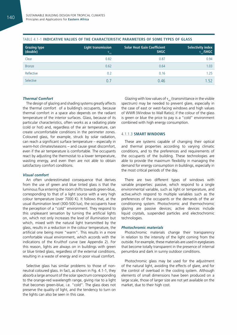
SUSTAINABLE BUILDING DESIGN FOR TROPICAL CLIMATES Principles and Applications for Eastern Africa140
Thermal ComfortThe design of glazing and shading systems greatly affects
the thermal comfort of a building’s occupants, because thermal comfort in a space also depends on the radiant temperature of the interior surfaces. Glass, because of its particular characteristics, often works as a radiating plate (cold or hot) and, regardless of the air temperature, can create uncomfortable conditions in the perimeter zones. Coloured glass, for example, struck by solar radiation, can reach a significant surface temperature – especially in warm-hot climates/seasons – and cause great discomfort, even if the air temperature is comfortable. The occupants react by adjusting the thermostat to a lower temperature, wasting energy, and even then are not able to obtain satisfactory comfort conditions.
Visual comfortAn often underestimated consequence that derives
from the use of green and blue tinted glass is that the luminous flux entering the room shifts towards green-blue, corresponding to that of a light source with a very high colour temperature (over 7000 K). It follows that, at the usual illumination level (300-500 lux), the occupants have the perception of a “cold” environment. They respond to this unpleasant sensation by turning the artificial lights on, which not only increases the level of illumination but which, mixed with the natural light transmitted by the glass, results in a reduction in the colour temperature, the artificial one being more “warm”. This results in a more comfortable visual environment, which accords with the indications of the Kruithof curve (see Appendix 2). For this reason, lights are always on in buildings with green or blue tinted glass, regardless of the external conditions, resulting in a waste of energy and in poor visual comfort.
Selective glass has similar problems to those of non-neutral coloured glass. In fact, as shown in Fig. 4.1-1, they absorb a large amount of the solar spectrum corresponding to the orange-red wavelength range, giving rise to a light that becomes green-blue, i.e. “cold”. The glass does not preserve the quality of light, and the tendency to turn on the lights can also be seen in this case.
Glazing with low values of tvis (transmittance in the visible spectrum) may be needed to prevent glare, especially in the case of east or west-facing windows and high values of WWR (Window to Wall Ratio); if the colour of the glass is green or blue the price to pay is a “cold” environment combined with high energy consumption.
4.1.1.3 smart WIndoWs
These are systems capable of changing their optical and thermal properties according to varying climatic conditions, and to the preferences and requirements of the occupants of the building. These technologies are able to provide the maximum flexibility in managing the demand for energy consumption in buildings, especially in the most critical periods of the day.
There are two different types of windows with variable properties: passive, which respond to a single environmental variable, such as light or temperature, and active,which respond to multiple variables such as the preferences of the occupants or the demands of the air conditioning system. Photochromic and thermochromic glazing are passive devices; active devices include liquid crystals, suspended particles and electrochromic technologies.
Photochromic materialsPhotochromic materials change their transparency
in relation to the intensity of the light coming from the outside. For example, these materials are used in eyeglasses that become totally transparent in the presence of internal penumbra and dark in sunny outdoor conditions.
Photochromic glass may be used for the adjustment of the natural light, avoiding the effects of glare, and for the control of overload in the cooling system. Although elements of small dimensions have been produced on a large scale, those of larger size are not yet available on the market, due to their high cost.
grazing type (double)
light transmission tvis
solar heat gain coefficient shgc
selectivity index tvis/shgc
Clear 0.82 0.87 0.94
Bronze 0.62 0.64 1.03
reflective 0.2 0.16 1.25
Selective 0.7 0.46 1.52
TABLe 4.1-1 IndIcatIve values of the characterIstIc parameters of some types of glass
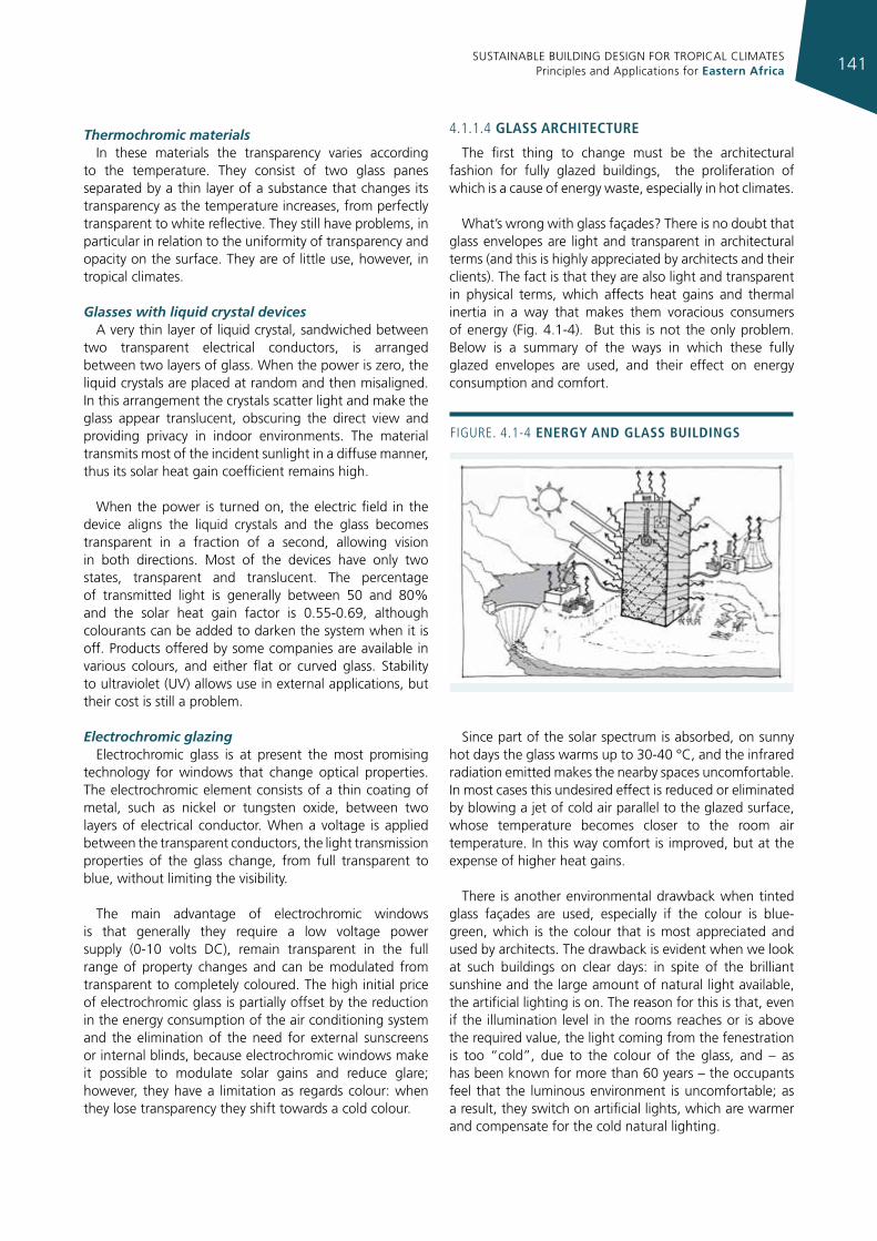
SUSTAINABLE BUILDING DESIGN FOR TROPICAL CLIMATES Principles and Applications for Eastern Africa 141
Thermochromic materialsIn these materials the transparency varies according
to the temperature. They consist of two glass panes separated by a thin layer of a substance that changes its transparency as the temperature increases, from perfectly transparent to white reflective. They still have problems, in particular in relation to the uniformity of transparency and opacity on the surface. They are of little use, however, in tropical climates.
Glasses with liquid crystal devicesA very thin layer of liquid crystal, sandwiched between
two transparent electrical conductors, is arranged between two layers of glass. When the power is zero, the liquid crystals are placed at random and then misaligned. In this arrangement the crystals scatter light and make the glass appear translucent, obscuring the direct view and providing privacy in indoor environments. The material transmits most of the incident sunlight in a diffuse manner, thus its solar heat gain coefficient remains high.
When the power is turned on, the electric field in the device aligns the liquid crystals and the glass becomes transparent in a fraction of a second, allowing vision in both directions. Most of the devices have only two states, transparent and translucent. The percentage of transmitted light is generally between 50 and 80% and the solar heat gain factor is 0.55-0.69, although colourants can be added to darken the system when it is off. Products offered by some companies are available in various colours, and either flat or curved glass. Stability to ultraviolet (UV) allows use in external applications, but their cost is still a problem.
Electrochromic glazingElectrochromic glass is at present the most promising
technology for windows that change optical properties. The electrochromic element consists of a thin coating of metal, such as nickel or tungsten oxide, between two layers of electrical conductor. When a voltage is applied between the transparent conductors, the light transmission properties of the glass change, from full transparent to blue, without limiting the visibility.
The main advantage of electrochromic windows is that generally they require a low voltage power supply (0-10 volts DC), remain transparent in the full range of property changes and can be modulated from transparent to completely coloured. The high initial price of electrochromic glass is partially offset by the reduction in the energy consumption of the air conditioning system and the elimination of the need for external sunscreens or internal blinds, because electrochromic windows make it possible to modulate solar gains and reduce glare; however, they have a limitation as regards colour: when they lose transparency they shift towards a cold colour.
4.1.1.4 glass archItecture
The first thing to change must be the architectural fashion for fully glazed buildings, the proliferation of which is a cause of energy waste, especially in hot climates.
What’s wrong with glass façades? There is no doubt that glass envelopes are light and transparent in architectural terms (and this is highly appreciated by architects and their clients). The fact is that they are also light and transparent in physical terms, which affects heat gains and thermal inertia in a way that makes them voracious consumers of energy (Fig. 4.1-4). But this is not the only problem. Below is a summary of the ways in which these fully glazed envelopes are used, and their effect on energy consumption and comfort.
Since part of the solar spectrum is absorbed, on sunny hot days the glass warms up to 30-40 °C, and the infrared radiation emitted makes the nearby spaces uncomfortable. In most cases this undesired effect is reduced or eliminated by blowing a jet of cold air parallel to the glazed surface, whose temperature becomes closer to the room air temperature. In this way comfort is improved, but at the expense of higher heat gains.
There is another environmental drawback when tinted glass façades are used, especially if the colour is blue-green, which is the colour that is most appreciated and used by architects. The drawback is evident when we look at such buildings on clear days: in spite of the brilliant sunshine and the large amount of natural light available, the artificial lighting is on. The reason for this is that, even if the illumination level in the rooms reaches or is above the required value, the light coming from the fenestration is too “cold”, due to the colour of the glass, and – as has been known for more than 60 years – the occupants feel that the luminous environment is uncomfortable; as a result, they switch on artificial lights, which are warmer and compensate for the cold natural lighting.
Figure. 4.1-4 energy and glass buIldIngs
SUSTAINABLE BUILDING DESIGN FOR TROPICAL CLIMATES Principles and Applications for Eastern Africa142
Another issue related to visual comfort is when clear glass is used. The benefit of a large aperture that lets in a flood of natural light is entirely cancelled out by the effect of glare on the occupants’ behaviour: they restore their visual comfort by obscuring the glass surface with curtains, Venetian blinds or whatever is available. The struggle for survival of the unfortunate occupants is clearly evident in all glazed buildings.
The final result on the energy balance of the building is easy to evaluate: there are high and uncontrolled solar gains in hot climates (the curtains inside, even if they are white, absorb solar energy that is transferred to the room) and the lights are always on.
Recently, to temper this undesirable effect, some leading architects have used external shading devices to protect the large glazed walls. It seems a good idea, but unfortunately although they cut off glare, light and outside vision are also cut off, and artificial lighting must be on all the time.
Glass is potentially a very effective material for low energy buildings thanks to the most recent technological developments, but fully glazed buildings exacerbate the problem of air conditioning in hot seasons/climates, increasing energy demands both because of the large solar gains and because of the induced need for artificial lighting in spite of natural light being always available.
The most effective way to stop the proliferation of energy wasting buildings is to develop and enforce appropriate building regulations dealing with energy conservation. In some countries, such as France, Spain and Portugal in Europe, and California in the US, there are limits to the maximum glazed area allowed in each façade, unless it can be demonstrated that the energy required for heating and cooling is less than a pre-set limit (see section 4.6).
DoubLE SkIn gLASS
The claimed advantages of double skin glass façade systems, compared to a single glass curtain are: greater energy efficiency (the heat loss is less than that of a single skin), better thermal comfort (the interspace is crossed by cold air, bringing the temperature of the inner glass to acceptable values), better sound control (greater attenuation of external noise) and the ability to control natural ventilation, all the while maintaining the architectural value of a light and transparent envelope.
The problem is that many of these claimed benefits are controversial or even contradicted by experimental evidence, sometimes conflicting with each other and in many cases lacking in scientific evidence.
A study carried out under the eu “intelligent Building” programme, “Best Façades*” showed that:
• the cost of double skin glass is 20-80% higher than that of single skin glass, and 100-150% higher than a normal façade (wall and windows). So, to offset this extra cost, significant energy savings are required;
• maintenance costs for the double skin are obviously higher than those for single skin, because four surfaces instead of two must be cleaned, and more often if this gap is crossed by outside air. These higher costs are partially offset by lower maintenance requirements for sunscreens that are not exposed to rain and wind, being placed in the cavity between the two skins;
• although it is true that a reduction in traffic noise is one of the advantages offered by the double skin, it is also true that in many cases an increase in noise transmission between indoor environments has been reported, due to the reflection of sound in the cavity;
• from the point of view of fire safety the double skin has been strongly criticised, since firemen would be forced to break two glass panes before they could enter the building from the outside, and because of the possible spread of fire through the interspace;
• double skin façades, compared to traditional ones, require more space, more resources and more energy for production and construction (see Appendix 1). Their environmental impact is also higher and reducing it requires compensating with much lower energy consumption and less impact during demolition;
• the performance of a double-skin building is highly dependent on climate and on how the façade is designed. A building with a double glass skin which is well designed for the Swedish climate would not work in Nairobi, and vice versa. Furthermore, the design solutions must be different for each façade. Consequently, to obtain good performances with a double skin it is necessary to carry out complex dynamic simulations, sometimes with models developed “ad hoc”: this is an indispensable precondition;
• experience in southern europe shows that the milder the climate the worse the double skin glass façade performs.
The results of this study indicate that any application of this technology in tropical climates should be excluded.
* BESTFACADE, Best Practice for Double Skin Façades (EIE/04/135/S07.38652, 2008), Publishable Report, WP5 Best Practice Guidelines, http://www.bestfacade.com
SUSTAINABLE BUILDING DESIGN FOR TROPICAL CLIMATES Principles and Applications for Eastern Africa 143
4.1.2 sIZIng and desIgn of openIngs
Designing a window is not just a matter for architects, because the design of the glazed surfaces has a great impact on the design of the HVAC system. Windows have a significant impact on energy consumption in a building’s perimeter spaces. The most direct impact is on the amount of energy needed for air conditioning.
If the windows are properly designed and the lighting system is well controlled, windows can eliminate or reduce the need for artificial lighting during the day by providing daylight, but this benefit may be outweighed by solar gains. Solar heat gain accounts for the majority of the cooling load in perimeter spaces with windows. It should also be considered that, although electricity consumption for artificial lighting decreases as the area of glass increases, provided that the area of the glass does not exceed 25% of the entire façade, beyond this value a sort of saturation is reached, and the savings in electricity achieved by continuing to increase the area of glass are very small, while consumption of energy for cooling continues to grow uniformly.
A designer’s first choice should be to minimize the amount of direct solar radiation that reaches the windows. If direct sunlight can be kept off the windows, then inexpensive clear glass can be used. By using windows with solar control, it may be possible to reduce the size of the air conditioning equipment; these savings in equipment, in turn, can help offset some of the additional costs of the solar protection.
Window and shading design are closely linked to perimeter zone comfort, regardless of air temperature. Comfort should be considered as seriously as energy in fenestration design.
Using operable fenestration systems to ventilate the building naturally also reduces HVAC energy consumption by reducing the number of hours during which the HVAC system operates. In highland climates a carefully designed natural ventilation system may eliminate the need for a mechanical cooling system
Energy-efficient window design reduces solar heat gain while offering high visible light transmittance to allow more daylight inside. Benefits include:
• smaller and less expensive air conditioning equipment required;
• lower cooling energy costs;
• lower lighting energy costs;
• potentially better dehumidification performance from the air conditioning system because there is less variability in the space’s cooling loads, thus the air conditioning system can be smaller and run at a more constant capacity.
4.1.2.1 recommendatIons and tIps for WIndoW
desIgn
Begin daylighting design early in the design process. A building’s orientation is critical for maximizing the use of diffused daylight and reducing direct solar penetration. The best orientations for daylight sources are north and south: the high angle of the sun is easy to control with a horizontal overhang.
Avoid east and west-facing windows for daylighting. The low angle of the sun makes it difficult to control direct sun penetration through the use of overhangs or other fixed shading devices. Any window orientation more than 15 degrees off true north or south requires careful assessment to avoid unwanted sun penetration.
The ideal orientation may not be possible in urban situations where plot sizes may be constrained. In such cases increase the surface area exposed to the south and north. This may be done by using light shafts, light wells or light courts such that the west and east-facing walls are shaded and receive diffused light.
Windows should provide three basic services: protect from rain and wind (when required); provide lighting; provide exterior view. Fulfilling these requirements is not free: a large window, which should provide the maximum light and the widest view, also lets in a large amount of solar radiation, with the consequent solar heat gain, and – if it is not properly designed – causes the very unpleasant phenomenon of glare.
Windows are a critical component for the quality of internal spaces, since they play a very important role in determining the level of comfort (both thermal and visual). Bear in mind that large windows require more control. The larger the window, the more critical the selection of the type of glass and the effectiveness of shading in order to control glare and solar gains.
Designing a window is not only a matter of size and shape, it is also a matter of glazing: the choice of the type of glass is of paramount importance for the energy and comfort performances of a window.
The choice of the size and type of glass surface depends on several factors. The climate of the place in which the building will be built must be considered and should always be balanced against both the functional and the aesthetic needs.
Direct glare and reflected glare can make people uncomfortable and can make it difficult for them to perform certain tasks. Glare reflecting off a computer screen, for example, may make it difficult or impossible to view the images on the screen.
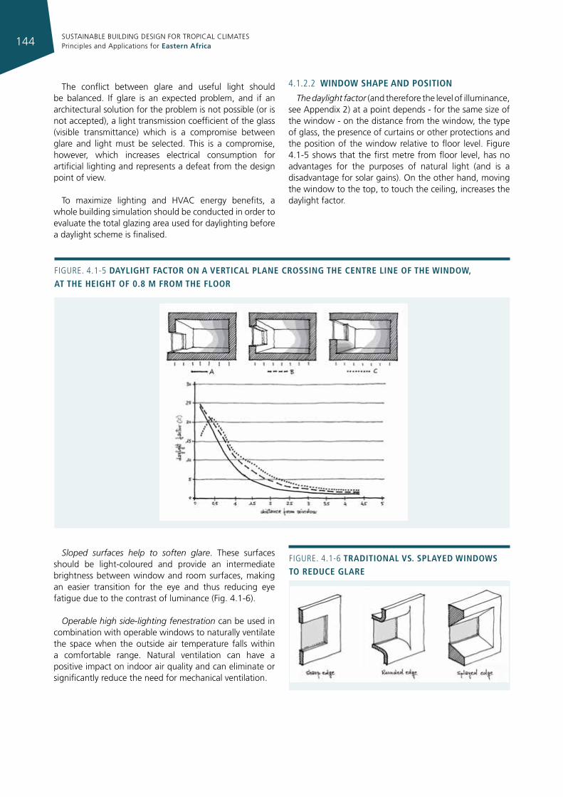
SUSTAINABLE BUILDING DESIGN FOR TROPICAL CLIMATES Principles and Applications for Eastern Africa144
The conflict between glare and useful light should be balanced. If glare is an expected problem, and if an architectural solution for the problem is not possible (or is not accepted), a light transmission coefficient of the glass (visible transmittance) which is a compromise between glare and light must be selected. This is a compromise, however, which increases electrical consumption for artificial lighting and represents a defeat from the design point of view.
To maximize lighting and HVAC energy benefits, a whole building simulation should be conducted in order to evaluate the total glazing area used for daylighting before a daylight scheme is finalised.
4.1.2.2 WIndoW shape and posItIon
The daylight factor (and therefore the level of illuminance, see Appendix 2) at a point depends - for the same size of the window - on the distance from the window, the type of glass, the presence of curtains or other protections and the position of the window relative to floor level. Figure 4.1-5 shows that the first metre from floor level, has no advantages for the purposes of natural light (and is a disadvantage for solar gains). On the other hand, moving the window to the top, to touch the ceiling, increases the daylight factor.
Figure. 4.1-6 tradItIonal vs. splayed WIndoWs to reduce glare
Figure. 4.1-5 daylIght factor on a vertIcal plane crossIng the centre lIne of the WIndoW, at the heIght of 0.8 m from the floor
Sloped surfaces help to soften glare. These surfaces should be light-coloured and provide an intermediate brightness between window and room surfaces, making an easier transition for the eye and thus reducing eye fatigue due to the contrast of luminance (Fig. 4.1-6).
Operable high side-lighting fenestration can be used in combination with operable windows to naturally ventilate the space when the outside air temperature falls within a comfortable range. Natural ventilation can have a positive impact on indoor air quality and can eliminate or significantly reduce the need for mechanical ventilation.
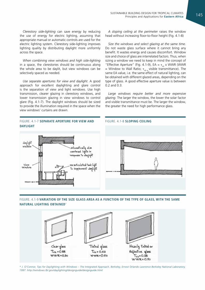
SUSTAINABLE BUILDING DESIGN FOR TROPICAL CLIMATES Principles and Applications for Eastern Africa 145
Clerestory side-lighting can save energy by reducing the use of energy for electric lighting, assuming that appropriate manual or automatic controls are used for the electric lighting system. Clerestory side-lighting improves lighting quality by distributing daylight more uniformly across the space.
When combining view windows and high side-lighting in a space, the clerestories should be continuous along the whole area to be daylit, but view windows can be selectively spaced as needed.
Use separate apertures for view and daylight. A good approach for excellent daylighting and glare control is the separation of view and light windows. Use high transmission, clearer glazing in clerestory windows, and lower transmission glazing in view windows to control glare (Fig. 4.1-7). The daylight windows should be sized to provide the illumination required in the space when the view windows’ curtains are drawn.
A sloping ceiling at the perimeter raises the window head without increasing floor-to-floor height (Fig. 4.1-8)
Size the windows and select glazing at the same time. Do not waste glass surface where it cannot bring any benefit. It wastes energy and causes discomfort. Window size and choice of glass are interrelated factors. Thus, when sizing a window we need to keep in mind the concept of “Effective Aperture” (Fig. 4.1-9), EA = tvis x WWR (WWR = Window to Wall Ratio; tvis = visible transmittance). The same EA value, i.e. the same effect of natural lighting, can be obtained with different glazed areas, depending on the type of glass. A good effective aperture value is between 0.2 and 0.3.
Large windows require better and more expensive glazing. The larger the window, the lower the solar factor and visible transmittance must be. The larger the window, the greater the need for high performance glass.
Figure. 4.1-7 separate aperture for vIeW and daylIght
Figure. 4.1-8 slopIng ceIlIng
* J. O’Connor, Tips for Daylighting with Windows – The Integrated Approach, Berkeley, Ernest Orlando Lawrence Berkeley National Laboratory, 1997. http://windows.lbl.gov/daylighting/designguide/designguide.html
Figure. 4.1-9 varIatIon of the sIze glass area as a functIon of the type of glass, WIth the same natural lIghtIng obtaIned*
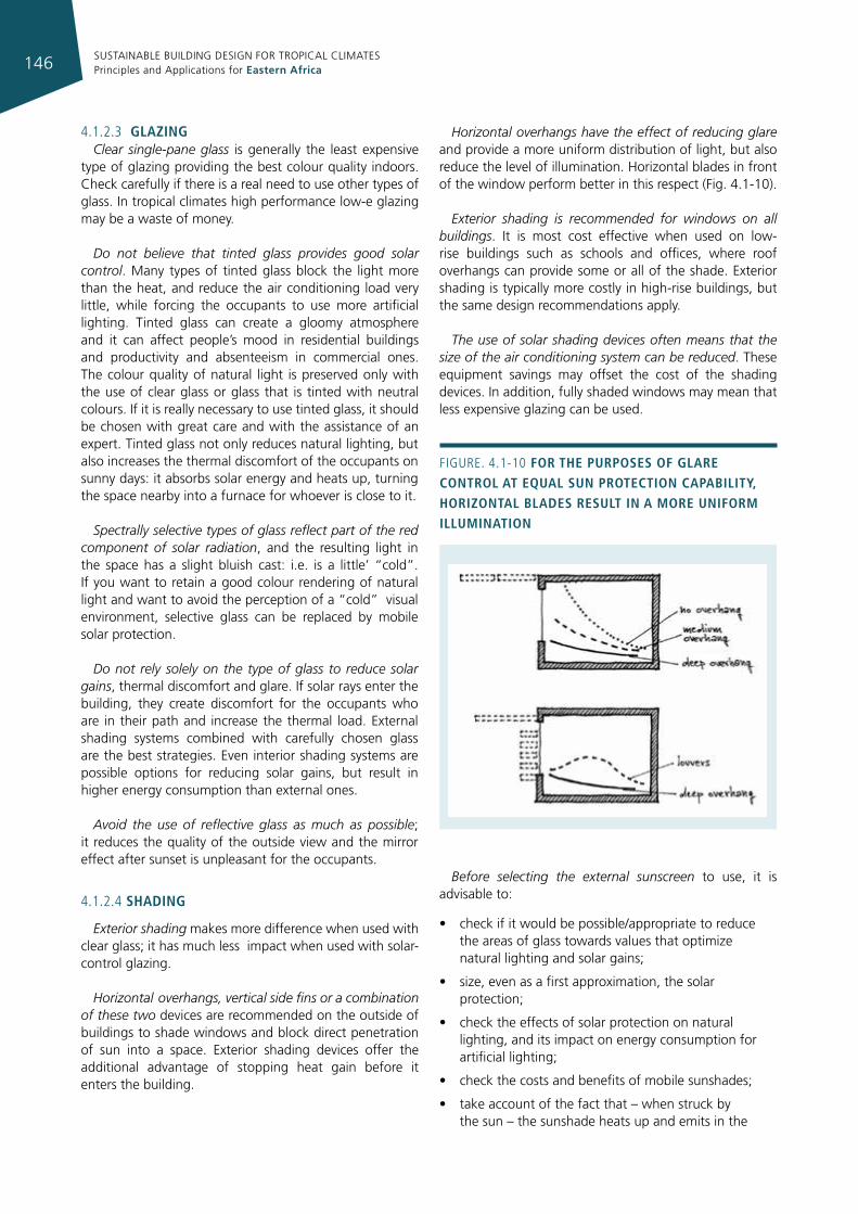
SUSTAINABLE BUILDING DESIGN FOR TROPICAL CLIMATES Principles and Applications for Eastern Africa146
4.1.2.3 glazIngClear single-pane glass is generally the least expensive
type of glazing providing the best colour quality indoors. Check carefully if there is a real need to use other types of glass. In tropical climates high performance low-e glazing may be a waste of money.
Do not believe that tinted glass provides good solar control. Many types of tinted glass block the light more than the heat, and reduce the air conditioning load very little, while forcing the occupants to use more artificial lighting. Tinted glass can create a gloomy atmosphere and it can affect people’s mood in residential buildings and productivity and absenteeism in commercial ones. The colour quality of natural light is preserved only with the use of clear glass or glass that is tinted with neutral colours. If it is really necessary to use tinted glass, it should be chosen with great care and with the assistance of an expert. Tinted glass not only reduces natural lighting, but also increases the thermal discomfort of the occupants on sunny days: it absorbs solar energy and heats up, turning the space nearby into a furnace for whoever is close to it.
Spectrally selective types of glass reflect part of the red component of solar radiation, and the resulting light in the space has a slight bluish cast: i.e. is a little’ “cold”. If you want to retain a good colour rendering of natural light and want to avoid the perception of a “cold” visual environment, selective glass can be replaced by mobile solar protection.
Do not rely solely on the type of glass to reduce solar gains, thermal discomfort and glare. If solar rays enter the building, they create discomfort for the occupants who are in their path and increase the thermal load. External shading systems combined with carefully chosen glass are the best strategies. Even interior shading systems are possible options for reducing solar gains, but result in higher energy consumption than external ones.
Avoid the use of reflective glass as much as possible; it reduces the quality of the outside view and the mirror effect after sunset is unpleasant for the occupants.
4.1.2.4 shadIng
Exterior shading makes more difference when used with clear glass; it has much less impact when used with solar-control glazing.
Horizontal overhangs, vertical side fins or a combination of these two devices are recommended on the outside of buildings to shade windows and block direct penetration of sun into a space. Exterior shading devices offer the additional advantage of stopping heat gain before it enters the building.
Horizontal overhangs have the effect of reducing glare and provide a more uniform distribution of light, but also reduce the level of illumination. Horizontal blades in front of the window perform better in this respect (Fig. 4.1-10).
Exterior shading is recommended for windows on all buildings. It is most cost effective when used on low-rise buildings such as schools and offices, where roof overhangs can provide some or all of the shade. Exterior shading is typically more costly in high-rise buildings, but the same design recommendations apply.
The use of solar shading devices often means that the size of the air conditioning system can be reduced. These equipment savings may offset the cost of the shading devices. In addition, fully shaded windows may mean that less expensive glazing can be used.
Before selecting the external sunscreen to use, it is advisable to:
• check if it would be possible/appropriate to reduce the areas of glass towards values that optimize natural lighting and solar gains;
• size, even as a first approximation, the solar protection;
• check the effects of solar protection on natural lighting, and its impact on energy consumption for artificial lighting;
• check the costs and benefits of mobile sunshades;
• take account of the fact that – when struck by the sun – the sunshade heats up and emits in the
Figure. 4.1-10 for the purposes of glare control at equal sun protectIon capabIlIty, horIzontal blades result In a more unIform IllumInatIon
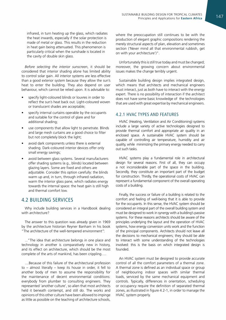
SUSTAINABLE BUILDING DESIGN FOR TROPICAL CLIMATES Principles and Applications for Eastern Africa 147
infrared, in turn heating up the glass, which radiates the heat inwards, especially if the solar protection is made of metal or glass. This results in the reduction in heat gain being attenuated. This phenomenon is particularly critical when the sunshade is located in the cavity of double skin glass.
Before selecting the interior sunscreen, it should be considered that interior shading alone has limited ability to control solar gain. All interior systems are less effective than a good exterior system because they allow the sun’s heat to enter the building. They also depend on user behaviour, which cannot be relied upon. It is advisable to:
• specify light-coloured blinds or louvres in order to reflect the sun’s heat back out. Light-coloured woven or translucent shades are acceptable;
• specify internal curtains operable by the occupants and suitable for the control of glare and for additional shading;
• use components that allow light to penetrate. Blinds and large mesh curtains are a good choice to filter but not completely block the light;
• avoid dark components unless there is external shading. Dark-coloured interior devices offer only small energy savings;
• avoid between glass systems. Several manufacturers offer shading systems (e.g., blinds) located between glazing layers. Some are fixed and others are adjustable. Consider this option carefully: the blinds warm up and, in turn, through infrared radiation, warm the interior glass pane, which radiates energy towards the internal space: the heat gain is still high and thermal comfort low.
4.2 buIldIng servIcesWhy include building services in a Handbook dealing
with architecture?
The answer to this question was already given in 1969 by the architecture historian Reyner Banham in his book “The architecture of the well-tempered environment”:
...”The idea that architecture belongs in one place and technology in another is comparatively new in history, and its effect on architecture, which should be the most complete of the arts of mankind, has been crippling.....
....Because of this failure of the architectural profession to – almost literally – keep its house in order, it fell to another body of men to assume the responsibility for the maintenance of decent environmental conditions: everybody from plumber to consulting engineers. They represented ‘another culture’, so alien that most architects held it beneath contempt, and still do. The works and opinions of this other culture have been allowed to impinge as little as possible on the teaching of architecture schools,
where the preoccupation still continues to be with the production of elegant graphic compositions rendering the merely structural aspects of plan, elevation and sometimes section (‘Never mind all that environmental rubbish, get on with your architecture’)”.
Unfortunately this is still true today and must be changed; moreover, the growing concern about environmental issues makes the change terribly urgent.
Sustainable building design implies integrated design, which means that architects and mechanical engineers must interact, just as both have to interact with the energy expert. There is no possibility of interaction if the architect does not have some basic knowledge of the technologies that are used with great expertise by mechanical engineers.
4.2.1 hvac Types and feaTures
HVAC (Heating, Ventilation and Air Conditioning) systems include a large variety of active technologies designed to provide thermal comfort and appropriate air quality in an enclosed space. A sustainable HVAC system should be capable of controlling air temperature, humidity and air quality, while minimizing the primary energy needed to carry out such tasks.
HVAC systems play a fundamental role in architectural design for several reasons. First of all, they can occupy a not inconsiderable part of the space in the building. Secondly, they constitute an important part of the budget for construction. Thirdly, the operational costs of HVAC can represent a fundamental component of the overall operating costs of a building.
Finally, the success or failure of a building is related to the comfort and feeling of well-being that it is able to provide for the occupants. In this sense, the HVAC system should be considered an integral part of the overall building system and must be designed to work in synergy with a building’s passive systems. For these reasons architects should be aware of the principles underlying the layout and the operation of HVAC systems, how energy conversion units work and the function of the principal components. Architects should not leave all the decisions to mechanical engineers; they should be able to interact with some understanding of the technologies involved: this is the basis on which integrated design is founded.
An HVAC system must be designed to provide accurate control of all the comfort parameters of a thermal zone. A thermal zone is defined as an individual space or group of neighbouring indoor spaces with similar thermal loads, serviced by the same mechanical equipment and controls. Typically, differences in orientation, scheduling or occupancy require the definition of separated thermal zones, as illustrated in figure 4.2-1, in order to manage the HVAC system properly.
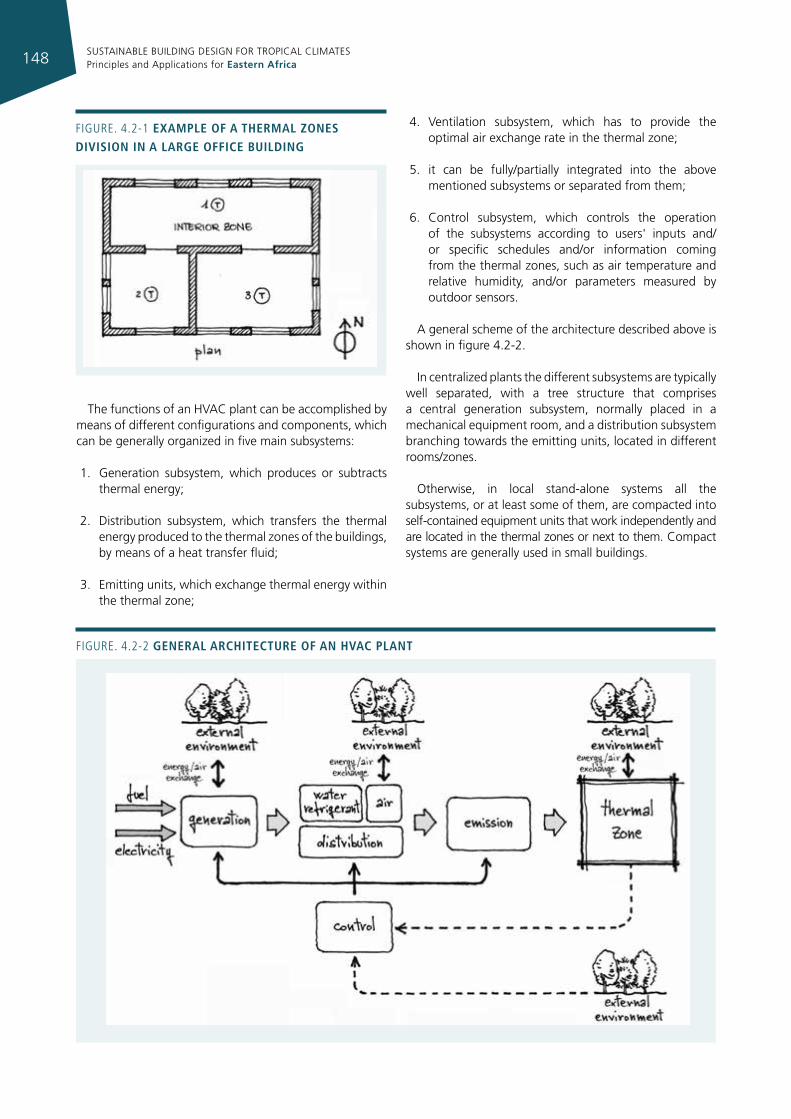
SUSTAINABLE BUILDING DESIGN FOR TROPICAL CLIMATES Principles and Applications for Eastern Africa148
The functions of an HVAC plant can be accomplished by means of different configurations and components, which can be generally organized in five main subsystems:
1. Generation subsystem, which produces or subtracts thermal energy;
2. Distribution subsystem, which transfers the thermal energy produced to the thermal zones of the buildings, by means of a heat transfer fluid;
3. Emitting units, which exchange thermal energy within the thermal zone;
4. Ventilation subsystem, which has to provide the optimal air exchange rate in the thermal zone;
5. it can be fully/partially integrated into the above mentioned subsystems or separated from them;
6. Control subsystem, which controls the operation of the subsystems according to users' inputs and/or specific schedules and/or information coming from the thermal zones, such as air temperature and relative humidity, and/or parameters measured by outdoor sensors.
A general scheme of the architecture described above is shown in figure 4.2-2.
In centralized plants the different subsystems are typically well separated, with a tree structure that comprises a central generation subsystem, normally placed in a mechanical equipment room, and a distribution subsystem branching towards the emitting units, located in different rooms/zones.
Otherwise, in local stand-alone systems all the subsystems, or at least some of them, are compacted into self-contained equipment units that work independently and are located in the thermal zones or next to them. Compact systems are generally used in small buildings.
Figure. 4.2-2 general archItecture of an hvac plant
Figure. 4.2-1 example of a thermal zones dIvIsIon In a large offIce buIldIng
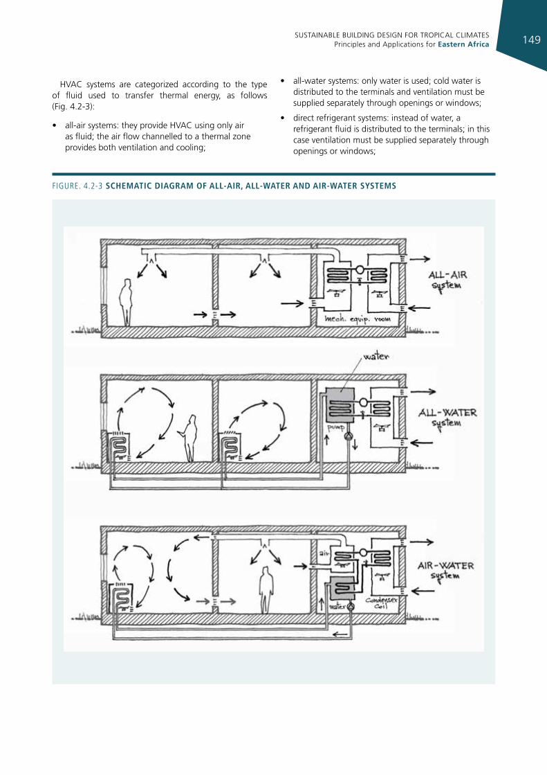
SUSTAINABLE BUILDING DESIGN FOR TROPICAL CLIMATES Principles and Applications for Eastern Africa 149
HVAC systems are categorized according to the type of fluid used to transfer thermal energy, as follows (Fig. 4.2-3):
• all-air systems: they provide HVAC using only air as fluid; the air flow channelled to a thermal zone provides both ventilation and cooling;
• all-water systems: only water is used; cold water is distributed to the terminals and ventilation must be supplied separately through openings or windows;
• direct refrigerant systems: instead of water, a refrigerant fluid is distributed to the terminals; in this case ventilation must be supplied separately through openings or windows;
Figure. 4.2-3 schematIc dIagram of all-aIr, all-Water and aIr-Water systems
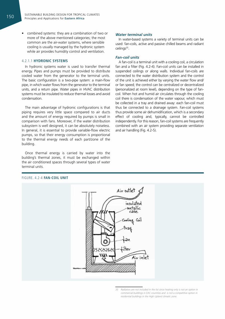
SUSTAINABLE BUILDING DESIGN FOR TROPICAL CLIMATES Principles and Applications for Eastern Africa150
• combined systems: they are a combination of two or more of the above mentioned categories; the most common are the air-water systems, where sensible cooling is usually managed by the hydronic system while air provides humidity control and ventilation.
4.2.1.1 hydronIc systems
In hydronic systems water is used to transfer thermal energy. Pipes and pumps must be provided to distribute cooled water from the generator to the terminal units. The basic configuration is a two-pipe system: a main-flow pipe, in which water flows from the generator to the terminal units, and a return pipe. Water pipes in HVAC distribution systems must be insulated to reduce thermal losses and avoid condensation.
The main advantage of hydronic configurations is that piping requires very little space compared to air ducts and the amount of energy required by pumps is small in comparison with fans. Moreover, if the water distribution subsystem is well designed, it can be absolutely noiseless. In general, it is essential to provide variable-flow electric pumps, so that their energy consumption is proportional to the thermal energy needs of each part/zone of the building.
Once thermal energy is carried by water into the building’s thermal zones, it must be exchanged within the air conditioned spaces through several types of water terminal units.
Water terminal units In water-based systems a variety of terminal units can be
used: fan-coils, active and passive chilled beams and radiant ceilings35.
Fan-coil unitsA fan-coil is a terminal unit with a cooling coil, a circulation
fan and a filter (Fig. 4.2-4). Fan-coil units can be installed in suspended ceilings or along walls. Individual fan-coils are connected to the water distribution system and the control of the unit is achieved either by varying the water flow and/or fan speed; the control can be centralized or decentralized (personalized at room level), depending on the type of fan-coil. When hot and humid air circulates through the cooling coil there is condensation of the water vapour, which must be collected in a tray and drained away: each fan-coil must thus be connected to a drainage system. Fan-coil systems thus provide some air dehumidification, which is a secondary effect of cooling and, typically, cannot be controlled independently. For this reason, fan-coil systems are frequently combined with an air system providing separate ventilation and air handling (Fig. 4.2-5).
35 Radiators are not included in the list since heating only is not an option in commercial buildings in EAC countries and is not a competitive option in residential buildings in the High Upland climatic zone.
Figure. 4.2-4 fan-coIl unIt
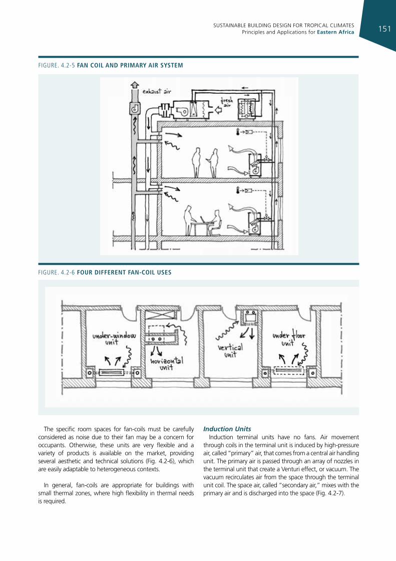
SUSTAINABLE BUILDING DESIGN FOR TROPICAL CLIMATES Principles and Applications for Eastern Africa 151
The specific room spaces for fan-coils must be carefully considered as noise due to their fan may be a concern for occupants. Otherwise, these units are very flexible and a variety of products is available on the market, providing several aesthetic and technical solutions (Fig. 4.2-6), which are easily adaptable to heterogeneous contexts.
In general, fan-coils are appropriate for buildings with small thermal zones, where high flexibility in thermal needs is required.
Induction UnitsInduction terminal units have no fans. Air movement
through coils in the terminal unit is induced by high-pressure air, called “primary” air, that comes from a central air handling unit. The primary air is passed through an array of nozzles in the terminal unit that create a Venturi effect, or vacuum. The vacuum recirculates air from the space through the terminal unit coil. The space air, called “secondary air,” mixes with the primary air and is discharged into the space (Fig. 4.2-7).
Figure. 4.2-5 fan coIl and prImary aIr system
Figure. 4.2-6 four dIfferent fan-coIl uses
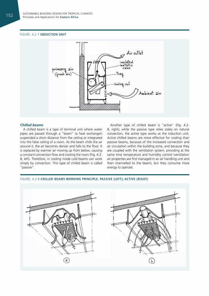
SUSTAINABLE BUILDING DESIGN FOR TROPICAL CLIMATES Principles and Applications for Eastern Africa152
Chilled beamsA chilled beam is a type of terminal unit where water
pipes are passed through a “beam” (a heat exchanger) suspended a short distance from the ceiling or integrated into the false ceiling of a room. As the beam chills the air around it, the air becomes denser and falls to the floor. It is replaced by warmer air moving up from below, causing a constant convection flow and cooling the room (Fig. 4.2-8, left). Therefore, in cooling mode cold beams can work simply by convection. This type of chilled beam is called “passive”.
Another type of chilled beam is “active” (Fig. 4.2-8, right); while the passive type relies solely on natural convection, the active type works as the induction unit. Active chilled beams are more effective for cooling than passive beams, because of the increased convection and air circulation within the building zone, and because they are coupled with the ventilation system, providing at the same time temperature and humidity control (ventilation air properties are first managed in an air handling unit and then channelled to the beam), but they consume more energy to operate.
Figure. 4.2-7 InductIon unIt
Figure. 4.2-8 chIlled beams WorkIng prIncIple. passIve (left); actIve (rIght)
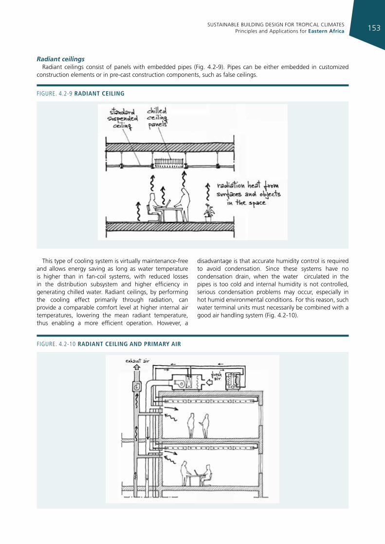
SUSTAINABLE BUILDING DESIGN FOR TROPICAL CLIMATES Principles and Applications for Eastern Africa 153
Radiant ceilingsRadiant ceilings consist of panels with embedded pipes (Fig. 4.2-9). Pipes can be either embedded in customized
construction elements or in pre-cast construction components, such as false ceilings.
Figure. 4.2-9 radIant ceIlIng
This type of cooling system is virtually maintenance-free and allows energy saving as long as water temperature is higher than in fan-coil systems, with reduced losses in the distribution subsystem and higher efficiency in generating chilled water. Radiant ceilings, by performing the cooling effect primarily through radiation, can provide a comparable comfort level at higher internal air temperatures, lowering the mean radiant temperature, thus enabling a more efficient operation. However, a
disadvantage is that accurate humidity control is required to avoid condensation. Since these systems have no condensation drain, when the water circulated in the pipes is too cold and internal humidity is not controlled, serious condensation problems may occur, especially in hot humid environmental conditions. For this reason, such water terminal units must necessarily be combined with a good air handling system (Fig. 4.2-10).
Figure. 4.2-10 radIant ceIlIng and prImary aIr
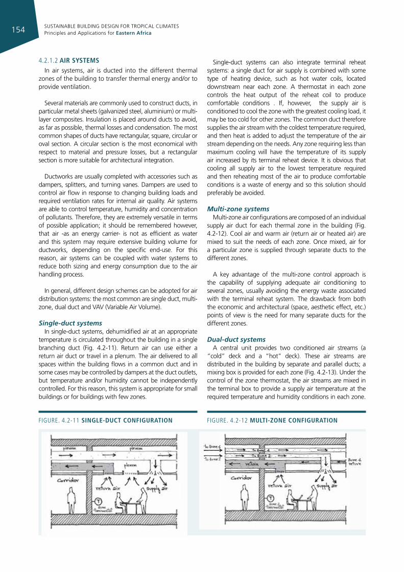
SUSTAINABLE BUILDING DESIGN FOR TROPICAL CLIMATES Principles and Applications for Eastern Africa154
4.2.1.2 aIr systemsIn air systems, air is ducted into the different thermal
zones of the building to transfer thermal energy and/or to provide ventilation.
Several materials are commonly used to construct ducts, in particular metal sheets (galvanized steel, aluminium) or multi-layer composites. Insulation is placed around ducts to avoid, as far as possible, thermal losses and condensation. The most common shapes of ducts have rectangular, square, circular or oval section. A circular section is the most economical with respect to material and pressure losses, but a rectangular section is more suitable for architectural integration.
Ductworks are usually completed with accessories such as dampers, splitters, and turning vanes. Dampers are used to control air flow in response to changing building loads and required ventilation rates for internal air quality. Air systems are able to control temperature, humidity and concentration of pollutants. Therefore, they are extremely versatile in terms of possible application; it should be remembered however, that air -as an energy carrier- is not as efficient as water and this system may require extensive building volume for ductworks, depending on the specific end-use. For this reason, air systems can be coupled with water systems to reduce both sizing and energy consumption due to the air handling process.
In general, different design schemes can be adopted for air distribution systems: the most common are single duct, multi-zone, dual duct and VAV (Variable Air Volume).
Single-duct systemsIn single-duct systems, dehumidified air at an appropriate
temperature is circulated throughout the building in a single branching duct (Fig. 4.2-11). Return air can use either a return air duct or travel in a plenum. The air delivered to all spaces within the building flows in a common duct and in some cases may be controlled by dampers at the duct outlets, but temperature and/or humidity cannot be independently controlled. For this reason, this system is appropriate for small buildings or for buildings with few zones.
Single-duct systems can also integrate terminal reheat systems: a single duct for air supply is combined with some type of heating device, such as hot water coils, located downstream near each zone. A thermostat in each zone controls the heat output of the reheat coil to produce comfortable conditions . If, however, the supply air is conditioned to cool the zone with the greatest cooling load, it may be too cold for other zones. The common duct therefore supplies the air stream with the coldest temperature required, and then heat is added to adjust the temperature of the air stream depending on the needs. Any zone requiring less than maximum cooling will have the temperature of its supply air increased by its terminal reheat device. It is obvious that cooling all supply air to the lowest temperature required and then reheating most of the air to produce comfortable conditions is a waste of energy and so this solution should preferably be avoided.
Multi-zone systemsMulti-zone air configurations are composed of an individual
supply air duct for each thermal zone in the building (Fig. 4.2-12). Cool air and warm air (return air or heated air) are mixed to suit the needs of each zone. Once mixed, air for a particular zone is supplied through separate ducts to the different zones.
A key advantage of the multi-zone control approach is the capability of supplying adequate air conditioning to several zones, usually avoiding the energy waste associated with the terminal reheat system. The drawback from both the economic and architectural (space, aesthetic effect, etc.) points of view is the need for many separate ducts for the different zones.
Dual-duct systemsA central unit provides two conditioned air streams (a
“cold” deck and a “hot” deck). These air streams are distributed in the building by separate and parallel ducts; a mixing box is provided for each zone (Fig. 4.2-13). Under the control of the zone thermostat, the air streams are mixed in the terminal box to provide a supply air temperature at the required temperature and humidity conditions in each zone.
Figure. 4.2-11 sIngle-duct confIguratIon Figure. 4.2-12 multI-zone confIguratIon
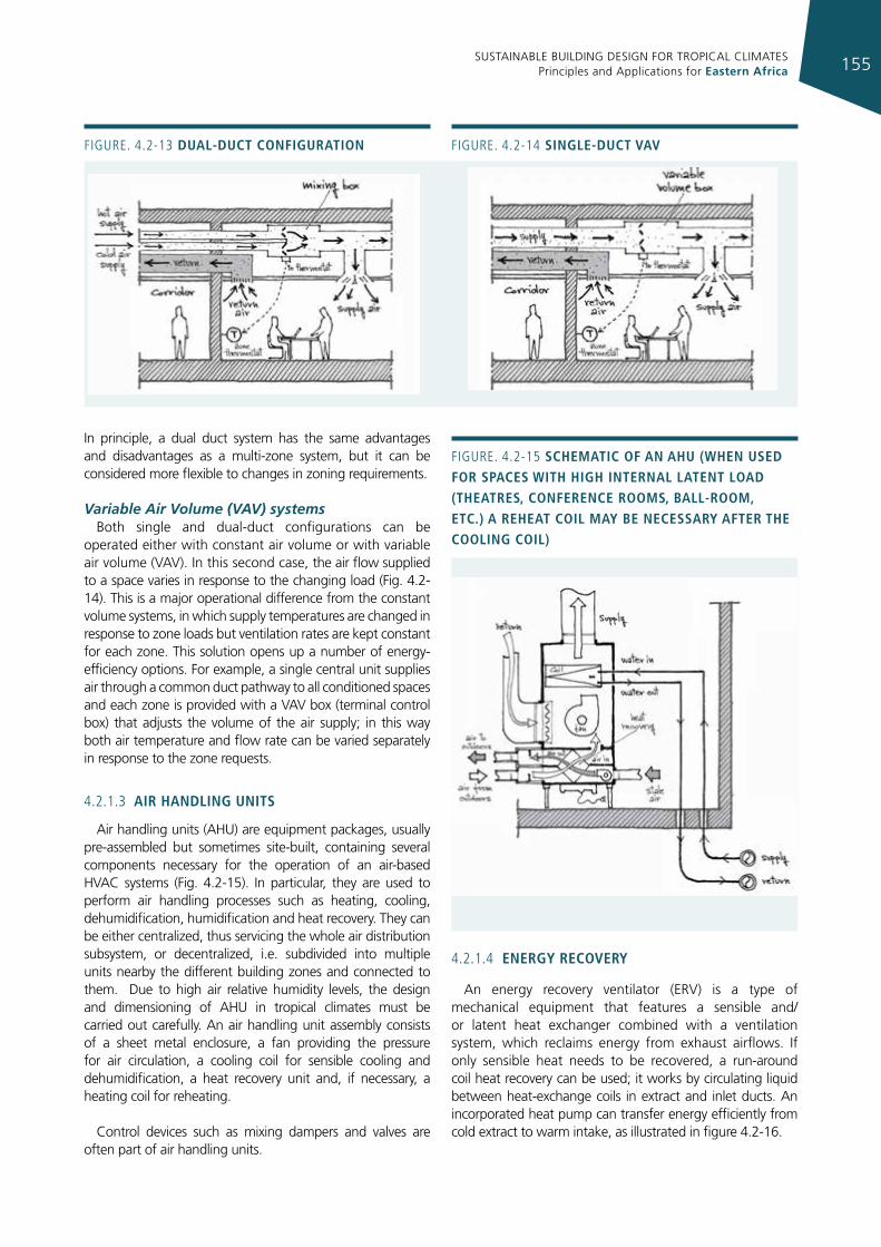
SUSTAINABLE BUILDING DESIGN FOR TROPICAL CLIMATES Principles and Applications for Eastern Africa 155
Figure. 4.2-13 dual-duct confIguratIon Figure. 4.2-14 sIngle-duct vav
In principle, a dual duct system has the same advantages and disadvantages as a multi-zone system, but it can be considered more flexible to changes in zoning requirements.
Variable Air Volume (VAV) systemsBoth single and dual-duct configurations can be
operated either with constant air volume or with variable air volume (VAV). In this second case, the air flow supplied to a space varies in response to the changing load (Fig. 4.2-14). This is a major operational difference from the constant volume systems, in which supply temperatures are changed in response to zone loads but ventilation rates are kept constant for each zone. This solution opens up a number of energy-efficiency options. For example, a single central unit supplies air through a common duct pathway to all conditioned spaces and each zone is provided with a VAV box (terminal control box) that adjusts the volume of the air supply; in this way both air temperature and flow rate can be varied separately in response to the zone requests.
4.2.1.3 aIr handlIng unIts
Air handling units (AHU) are equipment packages, usually pre-assembled but sometimes site-built, containing several components necessary for the operation of an air-based HVAC systems (Fig. 4.2-15). In particular, they are used to perform air handling processes such as heating, cooling, dehumidification, humidification and heat recovery. They can be either centralized, thus servicing the whole air distribution subsystem, or decentralized, i.e. subdivided into multiple units nearby the different building zones and connected to them. Due to high air relative humidity levels, the design and dimensioning of AHU in tropical climates must be carried out carefully. An air handling unit assembly consists of a sheet metal enclosure, a fan providing the pressure for air circulation, a cooling coil for sensible cooling and dehumidification, a heat recovery unit and, if necessary, a heating coil for reheating.
Control devices such as mixing dampers and valves are often part of air handling units.
4.2.1.4 energy recovery
An energy recovery ventilator (ERV) is a type of mechanical equipment that features a sensible and/or latent heat exchanger combined with a ventilation system, which reclaims energy from exhaust airflows. If only sensible heat needs to be recovered, a run-around coil heat recovery can be used; it works by circulating liquid between heat-exchange coils in extract and inlet ducts. An incorporated heat pump can transfer energy efficiently from cold extract to warm intake, as illustrated in figure 4.2-16.
Figure. 4.2-15 schematIc of an ahu (When used for spaces WIth hIgh Internal latent load (theatres, conference rooms, ball-room, etc.) a reheat coIl may be necessary after the coolIng coIl)
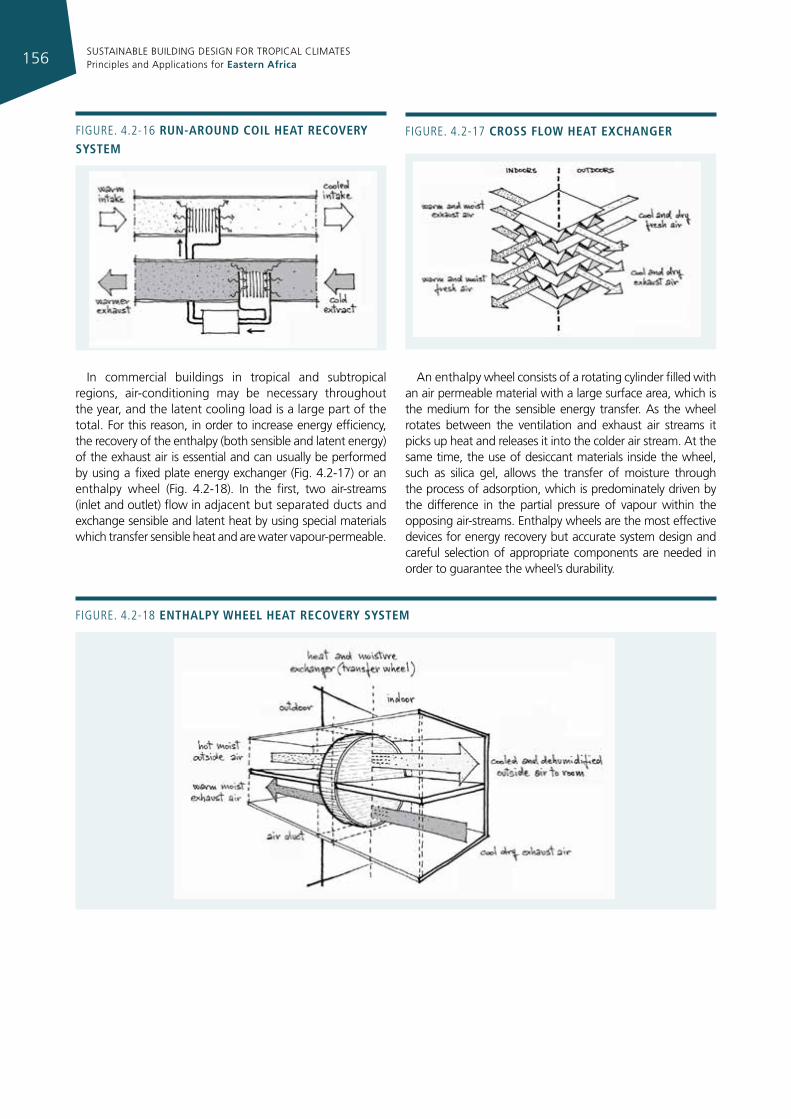
SUSTAINABLE BUILDING DESIGN FOR TROPICAL CLIMATES Principles and Applications for Eastern Africa156
In commercial buildings in tropical and subtropical regions, air-conditioning may be necessary throughout the year, and the latent cooling load is a large part of the total. For this reason, in order to increase energy efficiency, the recovery of the enthalpy (both sensible and latent energy) of the exhaust air is essential and can usually be performed by using a fixed plate energy exchanger (Fig. 4.2-17) or an enthalpy wheel (Fig. 4.2-18). In the first, two air-streams (inlet and outlet) flow in adjacent but separated ducts and exchange sensible and latent heat by using special materials which transfer sensible heat and are water vapour-permeable.
An enthalpy wheel consists of a rotating cylinder filled with an air permeable material with a large surface area, which is the medium for the sensible energy transfer. As the wheel rotates between the ventilation and exhaust air streams it picks up heat and releases it into the colder air stream. At the same time, the use of desiccant materials inside the wheel, such as silica gel, allows the transfer of moisture through the process of adsorption, which is predominately driven by the difference in the partial pressure of vapour within the opposing air-streams. Enthalpy wheels are the most effective devices for energy recovery but accurate system design and careful selection of appropriate components are needed in order to guarantee the wheel’s durability.
Figure. 4.2-16 run-around coIl heat recovery system
Figure. 4.2-17 cross floW heat exchanger
Figure. 4.2-18 enthalpy Wheel heat recovery system
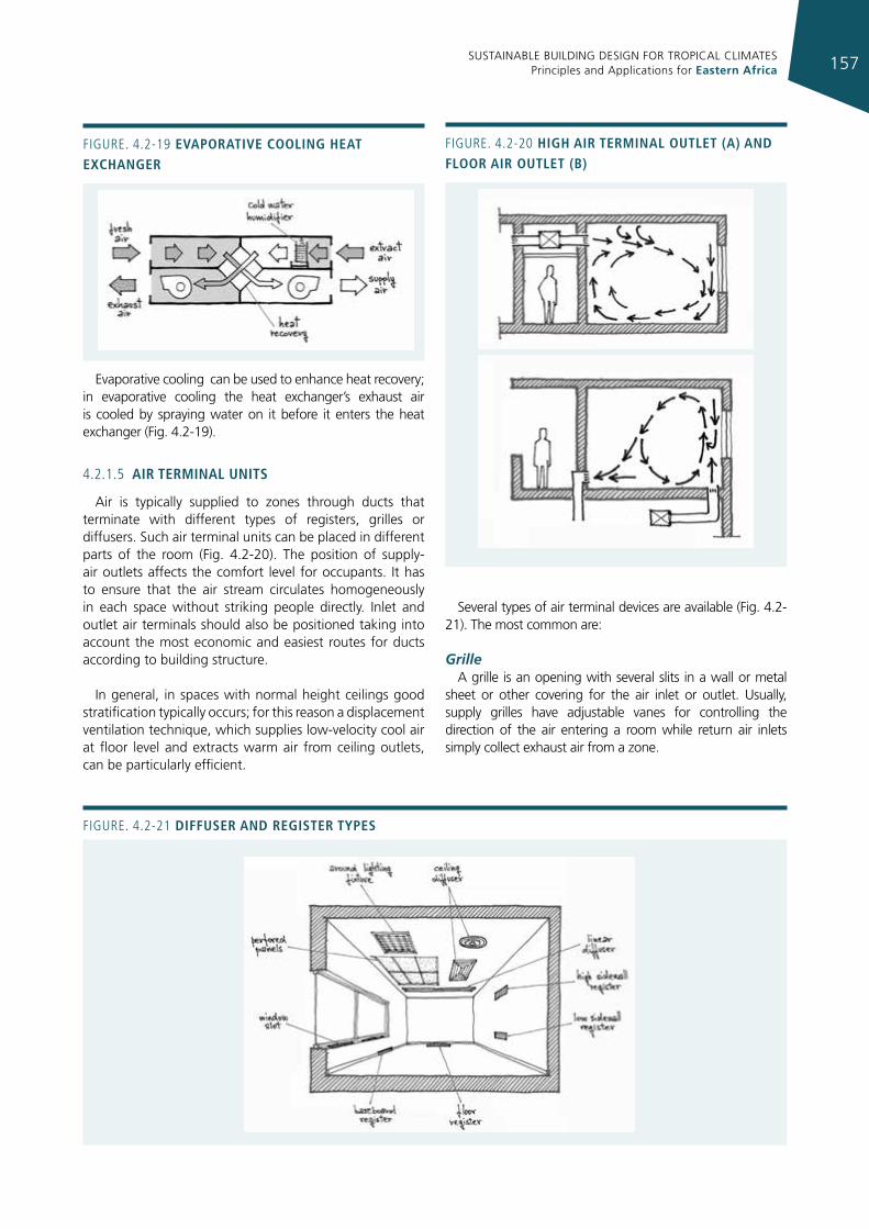
SUSTAINABLE BUILDING DESIGN FOR TROPICAL CLIMATES Principles and Applications for Eastern Africa 157
Evaporative cooling can be used to enhance heat recovery; in evaporative cooling the heat exchanger’s exhaust air is cooled by spraying water on it before it enters the heat exchanger (Fig. 4.2-19).
4.2.1.5 aIr termInal unIts
Air is typically supplied to zones through ducts that terminate with different types of registers, grilles or diffusers. Such air terminal units can be placed in different parts of the room (Fig. 4.2-20). The position of supply-air outlets affects the comfort level for occupants. It has to ensure that the air stream circulates homogeneously in each space without striking people directly. Inlet and outlet air terminals should also be positioned taking into account the most economic and easiest routes for ducts according to building structure.
In general, in spaces with normal height ceilings good stratification typically occurs; for this reason a displacement ventilation technique, which supplies low-velocity cool air at floor level and extracts warm air from ceiling outlets, can be particularly efficient.
Several types of air terminal devices are available (Fig. 4.2-21). The most common are:
Grille A grille is an opening with several slits in a wall or metal
sheet or other covering for the air inlet or outlet. Usually, supply grilles have adjustable vanes for controlling the direction of the air entering a room while return air inlets simply collect exhaust air from a zone.
Figure. 4.2-19 evaporatIve coolIng heat exchanger
Figure. 4.2-20 hIgh aIr termInal outlet (a) and floor aIr outlet (b)
Figure. 4.2-21 dIffuser and regIster types
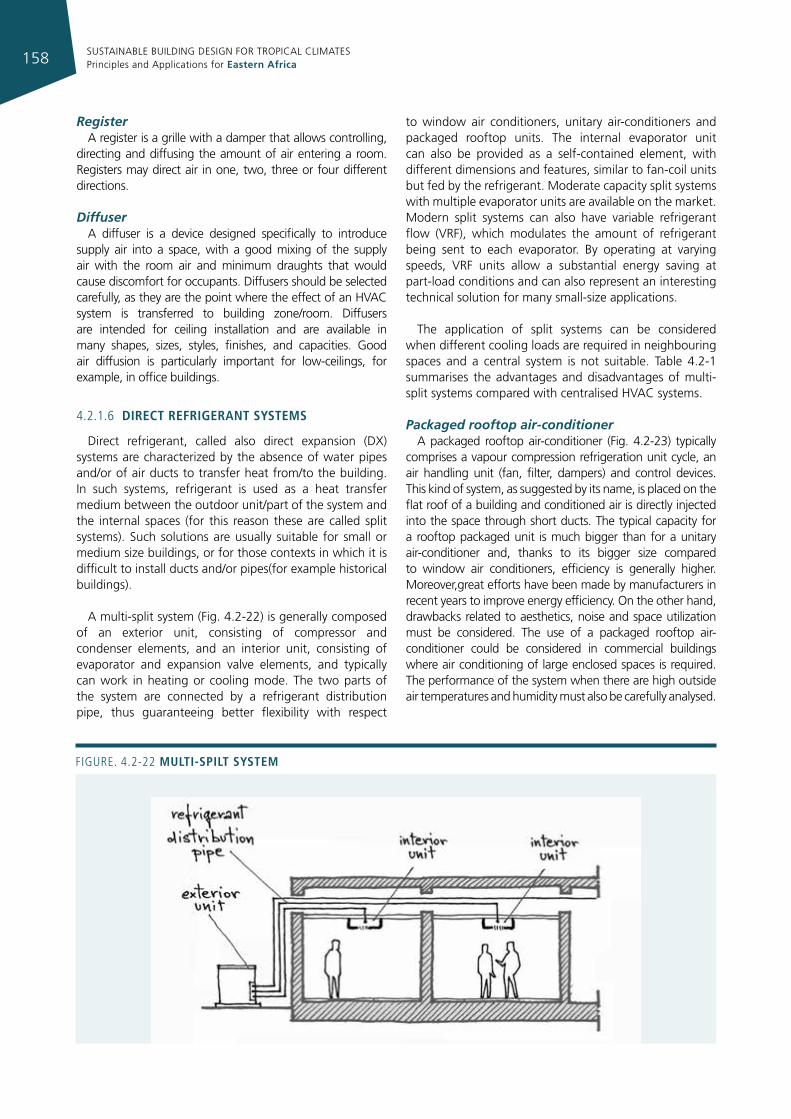
SUSTAINABLE BUILDING DESIGN FOR TROPICAL CLIMATES Principles and Applications for Eastern Africa158
Figure. 4.2-22 multI-spIlt system
RegisterA register is a grille with a damper that allows controlling,
directing and diffusing the amount of air entering a room. Registers may direct air in one, two, three or four different directions.
DiffuserA diffuser is a device designed specifically to introduce
supply air into a space, with a good mixing of the supply air with the room air and minimum draughts that would cause discomfort for occupants. Diffusers should be selected carefully, as they are the point where the effect of an HVAC system is transferred to building zone/room. Diffusers are intended for ceiling installation and are available in many shapes, sizes, styles, finishes, and capacities. Good air diffusion is particularly important for low-ceilings, for example, in office buildings.
4.2.1.6 dIrect refrIgerant systems
Direct refrigerant, called also direct expansion (DX) systems are characterized by the absence of water pipes and/or of air ducts to transfer heat from/to the building. In such systems, refrigerant is used as a heat transfer medium between the outdoor unit/part of the system and the internal spaces (for this reason these are called split systems). Such solutions are usually suitable for small or medium size buildings, or for those contexts in which it is difficult to install ducts and/or pipes(for example historical buildings).
A multi-split system (Fig. 4.2-22) is generally composed of an exterior unit, consisting of compressor and condenser elements, and an interior unit, consisting of evaporator and expansion valve elements, and typically can work in heating or cooling mode. The two parts of the system are connected by a refrigerant distribution pipe, thus guaranteeing better flexibility with respect
to window air conditioners, unitary air-conditioners and packaged rooftop units. The internal evaporator unit can also be provided as a self-contained element, with different dimensions and features, similar to fan-coil units but fed by the refrigerant. Moderate capacity split systems with multiple evaporator units are available on the market. Modern split systems can also have variable refrigerant flow (VRF), which modulates the amount of refrigerant being sent to each evaporator. By operating at varying speeds, VRF units allow a substantial energy saving at part-load conditions and can also represent an interesting technical solution for many small-size applications.
The application of split systems can be considered when different cooling loads are required in neighbouring spaces and a central system is not suitable. Table 4.2-1 summarises the advantages and disadvantages of multi-split systems compared with centralised HVAC systems.
Packaged rooftop air-conditioner A packaged rooftop air-conditioner (Fig. 4.2-23) typically
comprises a vapour compression refrigeration unit cycle, an air handling unit (fan, filter, dampers) and control devices. This kind of system, as suggested by its name, is placed on the flat roof of a building and conditioned air is directly injected into the space through short ducts. The typical capacity for a rooftop packaged unit is much bigger than for a unitary air-conditioner and, thanks to its bigger size compared to window air conditioners, efficiency is generally higher. Moreover,great efforts have been made by manufacturers in recent years to improve energy efficiency. On the other hand, drawbacks related to aesthetics, noise and space utilization must be considered. The use of a packaged rooftop air-conditioner could be considered in commercial buildings where air conditioning of large enclosed spaces is required. The performance of the system when there are high outside air temperatures and humidity must also be carefully analysed.
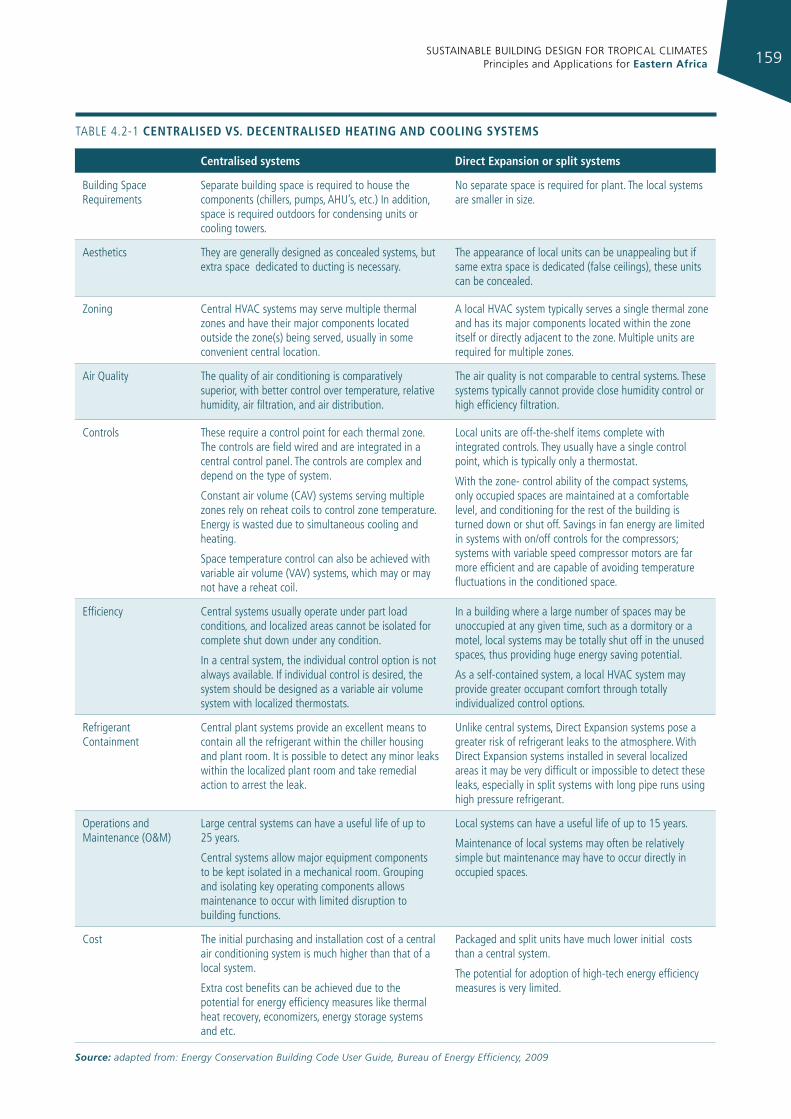
SUSTAINABLE BUILDING DESIGN FOR TROPICAL CLIMATES Principles and Applications for Eastern Africa 159
centralised systems direct expansion or split systems
Building Space requirements
Separate building space is required to house the components (chillers, pumps, AHu’s, etc.) in addition, space is required outdoors for condensing units or cooling towers.
No separate space is required for plant. The local systems are smaller in size.
Aesthetics They are generally designed as concealed systems, but extra space dedicated to ducting is necessary.
The appearance of local units can be unappealing but if same extra space is dedicated (false ceilings), these units can be concealed.
Zoning Central HVAC systems may serve multiple thermal zones and have their major components located outside the zone(s) being served, usually in some convenient central location.
A local HVAC system typically serves a single thermal zone and has its major components located within the zone itself or directly adjacent to the zone. Multiple units are required for multiple zones.
Air Quality The quality of air conditioning is comparatively superior, with better control over temperature, relative humidity, air filtration, and air distribution.
The air quality is not comparable to central systems. These systems typically cannot provide close humidity control or high efficiency filtration.
Controls These require a control point for each thermal zone. The controls are field wired and are integrated in a central control panel. The controls are complex and depend on the type of system.
Constant air volume (CAV) systems serving multiple zones rely on reheat coils to control zone temperature. energy is wasted due to simultaneous cooling and heating.
Space temperature control can also be achieved with variable air volume (VAV) systems, which may or may not have a reheat coil.
Local units are off-the-shelf items complete with integrated controls. They usually have a single control point, which is typically only a thermostat.
With the zone- control ability of the compact systems, only occupied spaces are maintained at a comfortable level, and conditioning for the rest of the building is turned down or shut off. Savings in fan energy are limited in systems with on/off controls for the compressors; systems with variable speed compressor motors are far more efficient and are capable of avoiding temperature fluctuations in the conditioned space.
efficiency Central systems usually operate under part load conditions, and localized areas cannot be isolated for complete shut down under any condition.
in a central system, the individual control option is not always available. if individual control is desired, the system should be designed as a variable air volume system with localized thermostats.
in a building where a large number of spaces may be unoccupied at any given time, such as a dormitory or a motel, local systems may be totally shut off in the unused spaces, thus providing huge energy saving potential.
As a self-contained system, a local HVAC system may provide greater occupant comfort through totally individualized control options.
refrigerant Containment
Central plant systems provide an excellent means to contain all the refrigerant within the chiller housing and plant room. it is possible to detect any minor leaks within the localized plant room and take remedial action to arrest the leak.
unlike central systems, Direct expansion systems pose a greater risk of refrigerant leaks to the atmosphere. With Direct expansion systems installed in several localized areas it may be very difficult or impossible to detect these leaks, especially in split systems with long pipe runs using high pressure refrigerant.
Operations and Maintenance (O&M)
Large central systems can have a useful life of up to 25 years.
Central systems allow major equipment components to be kept isolated in a mechanical room. grouping and isolating key operating components allows maintenance to occur with limited disruption to building functions.
Local systems can have a useful life of up to 15 years.
Maintenance of local systems may often be relatively simple but maintenance may have to occur directly in occupied spaces.
Cost The initial purchasing and installation cost of a central air conditioning system is much higher than that of a local system.
extra cost benefits can be achieved due to the potential for energy efficiency measures like thermal heat recovery, economizers, energy storage systems and etc.
Packaged and split units have much lower initial costs than a central system.
The potential for adoption of high-tech energy efficiency measures is very limited.
TABLe 4.2-1 centralIsed vs. decentralIsed heatIng and coolIng systems
Source: adapted from: Energy Conservation Building Code User Guide, Bureau of Energy Efficiency, 2009
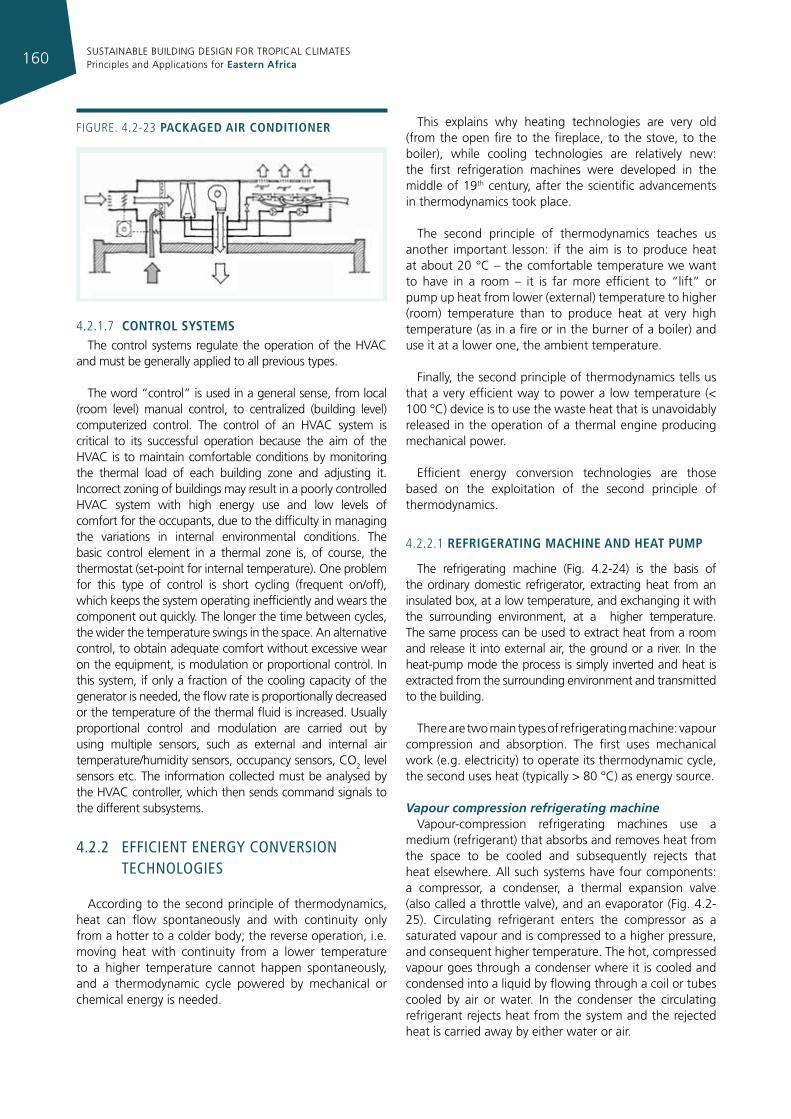
SUSTAINABLE BUILDING DESIGN FOR TROPICAL CLIMATES Principles and Applications for Eastern Africa160
4.2.1.7 control systemsThe control systems regulate the operation of the HVAC
and must be generally applied to all previous types.
The word “control” is used in a general sense, from local (room level) manual control, to centralized (building level) computerized control. The control of an HVAC system is critical to its successful operation because the aim of the HVAC is to maintain comfortable conditions by monitoring the thermal load of each building zone and adjusting it. Incorrect zoning of buildings may result in a poorly controlled HVAC system with high energy use and low levels of comfort for the occupants, due to the difficulty in managing the variations in internal environmental conditions. The basic control element in a thermal zone is, of course, the thermostat (set-point for internal temperature). One problem for this type of control is short cycling (frequent on/off), which keeps the system operating inefficiently and wears the component out quickly. The longer the time between cycles, the wider the temperature swings in the space. An alternative control, to obtain adequate comfort without excessive wear on the equipment, is modulation or proportional control. In this system, if only a fraction of the cooling capacity of the generator is needed, the flow rate is proportionally decreased or the temperature of the thermal fluid is increased. Usually proportional control and modulation are carried out by using multiple sensors, such as external and internal air temperature/humidity sensors, occupancy sensors, CO2 level sensors etc. The information collected must be analysed by the HVAC controller, which then sends command signals to the different subsystems.
4.2.2 effIcIenT energy conversIon TechnologIes
According to the second principle of thermodynamics, heat can flow spontaneously and with continuity only from a hotter to a colder body; the reverse operation, i.e. moving heat with continuity from a lower temperature to a higher temperature cannot happen spontaneously, and a thermodynamic cycle powered by mechanical or chemical energy is needed.
This explains why heating technologies are very old (from the open fire to the fireplace, to the stove, to the boiler), while cooling technologies are relatively new: the first refrigeration machines were developed in the middle of 19th century, after the scientific advancements in thermodynamics took place.
The second principle of thermodynamics teaches us another important lesson: if the aim is to produce heat at about 20 °C – the comfortable temperature we want to have in a room – it is far more efficient to “lift” or pump up heat from lower (external) temperature to higher (room) temperature than to produce heat at very high temperature (as in a fire or in the burner of a boiler) and use it at a lower one, the ambient temperature.
Finally, the second principle of thermodynamics tells us that a very efficient way to power a low temperature (< 100 °C) device is to use the waste heat that is unavoidably released in the operation of a thermal engine producing mechanical power.
Efficient energy conversion technologies are those based on the exploitation of the second principle of thermodynamics.
4.2.2.1 refrIgeratIng machIne and heat pump
The refrigerating machine (Fig. 4.2-24) is the basis of the ordinary domestic refrigerator, extracting heat from an insulated box, at a low temperature, and exchanging it with the surrounding environment, at a higher temperature. The same process can be used to extract heat from a room and release it into external air, the ground or a river. In the heat-pump mode the process is simply inverted and heat is extracted from the surrounding environment and transmitted to the building.
There are two main types of refrigerating machine: vapour compression and absorption. The first uses mechanical work (e.g. electricity) to operate its thermodynamic cycle, the second uses heat (typically > 80 °C) as energy source.
Vapour compression refrigerating machineVapour-compression refrigerating machines use a
medium (refrigerant) that absorbs and removes heat from the space to be cooled and subsequently rejects that heat elsewhere. All such systems have four components: a compressor, a condenser, a thermal expansion valve (also called a throttle valve), and an evaporator (Fig. 4.2-25). Circulating refrigerant enters the compressor as a saturated vapour and is compressed to a higher pressure, and consequent higher temperature. The hot, compressed vapour goes through a condenser where it is cooled and condensed into a liquid by flowing through a coil or tubes cooled by air or water. In the condenser the circulating refrigerant rejects heat from the system and the rejected heat is carried away by either water or air.
Figure. 4.2-23 packaged aIr condItIoner
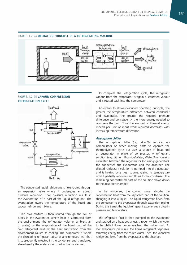
SUSTAINABLE BUILDING DESIGN FOR TROPICAL CLIMATES Principles and Applications for Eastern Africa 161
The condensed liquid refrigerant is next routed through an expansion valve where it undergoes an abrupt pressure reduction. That pressure reduction results in the evaporation of a part of the liquid refrigerant. The evaporation lowers the temperature of the liquid and vapour refrigerant mixture.
The cold mixture is then routed through the coil or tubes in the evaporator, where heat is subtracted from the environment (the refrigerator volume, ambient air or water) by the evaporation of the liquid part of the cold refrigerant mixture; the heat subtraction from the environment causes its cooling. The evaporator is where the circulating refrigerant absorbs and removes heat that is subsequently rejected in the condenser and transferred elsewhere by the water or air used in the condenser.
To complete the refrigeration cycle, the refrigerant vapour from the evaporator is again a saturated vapour and is routed back into the compressor.
According to above-described operating principle, the greater the temperature difference between condenser and evaporator, the greater the required pressure difference and consequently the more energy needed to compress the fluid. Thus the amount of thermal energy moved per unit of input work required decreases with increasing temperature difference.
Absorption chillerThe absorption chiller (Fig. 4.2-26) requires no
compressors or other moving parts to operate the thermodynamic cycle but uses a source of heat and a regenerator in place of compressor. A refrigerant solution (e.g. Lithium Bromide/Water, Water/Ammonia) is circulated between the regenerator (or simply generator), the condenser, the evaporator, and the absorber. The diluted refrigerant solution is pumped into the generator and is heated by a heat source, raising its temperature until it partially vaporizes and flows to the condenser. The remaining concentrated part of the solution flows down to the absorber chamber.
In the condenser, the cooling water absorbs the condensation heat from the vaporized part of the solution, changing it into a liquid. The liquid refrigerant flows from the condenser to the evaporator through expansion piping. During this transit the liquid refrigerant experiences a drop in pressure and temperature.
The refrigerant fluid is then pumped to the evaporator and sprayed on a heat exchanger, through which the water to be chilled flows before reaching the indoor unit. At low evaporator pressures, the liquid refrigerant vaporizes, removing energy from the chilled water. Then the vaporized refrigerant flows from the evaporator to the absorber.
Figure. 4.2-24 operatIng prIncIple of a refrIgeratIng machIne
Figure. 4.2-25 vapour-compressIon refrIgeratIon cycle
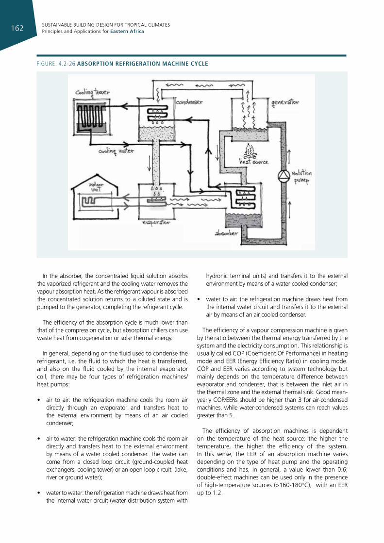
SUSTAINABLE BUILDING DESIGN FOR TROPICAL CLIMATES Principles and Applications for Eastern Africa162
In the absorber, the concentrated liquid solution absorbs the vaporized refrigerant and the cooling water removes the vapour absorption heat. As the refrigerant vapour is absorbed the concentrated solution returns to a diluted state and is pumped to the generator, completing the refrigerant cycle.
The efficiency of the absorption cycle is much lower than that of the compression cycle, but absorption chillers can use waste heat from cogeneration or solar thermal energy.
In general, depending on the fluid used to condense the refrigerant, i.e. the fluid to which the heat is transferred, and also on the fluid cooled by the internal evaporator coil, there may be four types of refrigeration machines/heat pumps:
• air to air: the refrigeration machine cools the room air directly through an evaporator and transfers heat to the external environment by means of an air cooled condenser;
• air to water: the refrigeration machine cools the room air directly and transfers heat to the external environment by means of a water cooled condenser. The water can come from a closed loop circuit (ground-coupled heat exchangers, cooling tower) or an open loop circuit (lake, river or ground water);
• water to water: the refrigeration machine draws heat from the internal water circuit (water distribution system with
hydronic terminal units) and transfers it to the external environment by means of a water cooled condenser;
• water to air: the refrigeration machine draws heat from the internal water circuit and transfers it to the external air by means of an air cooled condenser.
The efficiency of a vapour compression machine is given by the ratio between the thermal energy transferred by the system and the electricity consumption. This relationship is usually called COP (Coefficient Of Performance) in heating mode and EER (Energy Efficiency Ratio) in cooling mode. COP and EER varies according to system technology but mainly depends on the temperature difference between evaporator and condenser, that is between the inlet air in the thermal zone and the external thermal sink. Good mean-yearly COP/EERs should be higher than 3 for air-condensed machines, while water-condensed systems can reach values greater than 5.
The efficiency of absorption machines is dependent on the temperature of the heat source: the higher the temperature, the higher the efficiency of the system. In this sense, the EER of an absorption machine varies depending on the type of heat pump and the operating conditions and has, in general, a value lower than 0.6; double-effect machines can be used only in the presence of high-temperature sources (>160-180°C), with an EER up to 1.2.
Figure. 4.2-26 absorptIon refrIgeratIon machIne cycle
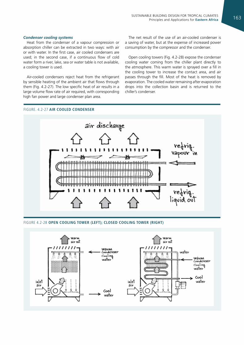
SUSTAINABLE BUILDING DESIGN FOR TROPICAL CLIMATES Principles and Applications for Eastern Africa 163
Condenser cooling systems Heat from the condenser of a vapour compression or
absorption chiller can be extracted in two ways: with air or with water. In the first case, air cooled condensers are used; in the second case, if a continuous flow of cold water form a river, lake, sea or water table is not available, a cooling tower is used.
Air-cooled condensers reject heat from the refrigerant by sensible heating of the ambient air that flows through them (Fig. 4.2-27). The low specific heat of air results in a large volume flow rate of air required, with corresponding high fan power and large condenser plan area.
The net result of the use of an air-cooled condenser is a saving of water, but at the expense of increased power consumption by the compressor and the condenser.
Open cooling towers (Fig. 4.2-28) expose the condenser cooling water coming from the chiller plant directly to the atmosphere. This warm water is sprayed over a fill in the cooling tower to increase the contact area, and air passes through the fill. Most of the heat is removed by evaporation. The cooled water remaining after evaporation drops into the collection basin and is returned to the chiller’s condenser.
Figure. 4.2-27 aIr cooled condenser
Figure 4.2-28 open coolIng toWer (left); closed coolIng toWer (rIght)
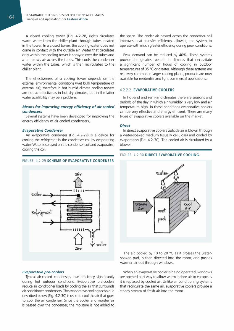
SUSTAINABLE BUILDING DESIGN FOR TROPICAL CLIMATES Principles and Applications for Eastern Africa164
A closed cooling tower (Fig. 4.2-28, right) circulates warm water from the chiller plant through tubes located in the tower. In a closed tower, the cooling water does not come in contact with the outside air. Water that circulates only within the cooling tower is sprayed over the tubes and a fan blows air across the tubes. This cools the condenser water within the tubes, which is then recirculated to the chiller plant.
The effectiveness of a cooling tower depends on the external environmental conditions (wet bulb temperature of external air); therefore in hot humid climate cooling towers are not as effective as in hot dry climates, but in the latter water availability may be a problem.
Means for improving energy efficiency of air cooled condensers
Several systems have been developed for improving the energy efficiency of air cooled condensers,.
Evaporative Condenser An evaporative condenser (Fig. 4.2-29) is a device for
cooling the refrigerant in the condenser coil by evaporating water. Water is sprayed on the condenser coil and evaporates, cooling the coil.
Evaporative pre-coolersTypical air-cooled condensers lose efficiency significantly
during hot outdoor conditions. Evaporative pre-coolers reduce air conditioner loads by cooling the air that surrounds air conditioner condensers. The evaporative cooling technique described below (Fig. 4.2-30) is used to cool the air that goes to cool the air condenser. Since the cooler and moister air is passed over the condenser, the moisture is not added to
the space. The cooler air passed across the condenser coil improves heat transfer efficiency, allowing the system to operate with much greater efficiency during peak conditions.
Peak demand can be reduced by 40%. These systems provide the greatest benefit in climates that necessitate a significant number of hours of cooling in outdoor temperatures of 35 °C or greater. Although these systems are relatively common in larger cooling plants, products are now available for residential and light commercial applications.
4.2.2.2 evaporatIve coolers
In hot-arid and semi-arid climates there are seasons and periods of the day in which air humidity is very low and air temperature high. In these conditions evaporative coolers can be very effective and energy efficient. There are many types of evaporative coolers available on the market.
DirectIn direct evaporative coolers outside air is blown through
a water-soaked medium (usually cellulose) and cooled by evaporation (Fig. 4.2-30). The cooled air is circulated by a blower.
The air, cooled by 10 to 20 °C as it crosses the water-soaked pad, is then directed into the room, and pushes warmer air out through windows.
When an evaporative cooler is being operated, windows are opened part way to allow warm indoor air to escape as it is replaced by cooled air. Unlike air conditioning systems that recirculate the same air, evaporative coolers provide a steady stream of fresh air into the room.
Figure. 4.2-29 scheme of evaporatIve condenser
Figure. 4.2-30 dIrect evaporatIve coolIng.
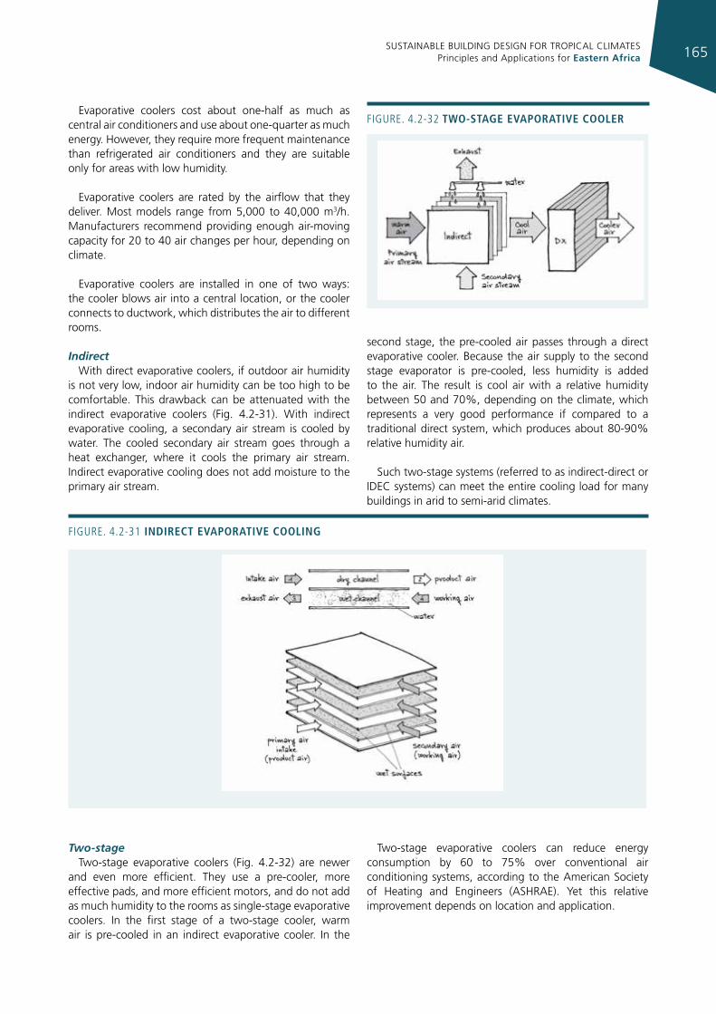
SUSTAINABLE BUILDING DESIGN FOR TROPICAL CLIMATES Principles and Applications for Eastern Africa 165
Evaporative coolers cost about one-half as much as central air conditioners and use about one-quarter as much energy. However, they require more frequent maintenance than refrigerated air conditioners and they are suitable only for areas with low humidity.
Evaporative coolers are rated by the airflow that they deliver. Most models range from 5,000 to 40,000 m3/h. Manufacturers recommend providing enough air-moving capacity for 20 to 40 air changes per hour, depending on climate.
Evaporative coolers are installed in one of two ways: the cooler blows air into a central location, or the cooler connects to ductwork, which distributes the air to different rooms.
IndirectWith direct evaporative coolers, if outdoor air humidity
is not very low, indoor air humidity can be too high to be comfortable. This drawback can be attenuated with the indirect evaporative coolers (Fig. 4.2-31). With indirect evaporative cooling, a secondary air stream is cooled by water. The cooled secondary air stream goes through a heat exchanger, where it cools the primary air stream. Indirect evaporative cooling does not add moisture to the primary air stream.
Two-stageTwo-stage evaporative coolers (Fig. 4.2-32) are newer
and even more efficient. They use a pre-cooler, more effective pads, and more efficient motors, and do not add as much humidity to the rooms as single-stage evaporative coolers. In the first stage of a two-stage cooler, warm air is pre-cooled in an indirect evaporative cooler. In the
second stage, the pre-cooled air passes through a direct evaporative cooler. Because the air supply to the second stage evaporator is pre-cooled, less humidity is added to the air. The result is cool air with a relative humidity between 50 and 70%, depending on the climate, which represents a very good performance if compared to a traditional direct system, which produces about 80-90% relative humidity air.
Such two-stage systems (referred to as indirect-direct or IDEC systems) can meet the entire cooling load for many buildings in arid to semi-arid climates.
Two-stage evaporative coolers can reduce energy consumption by 60 to 75% over conventional air conditioning systems, according to the American Society of Heating and Engineers (ASHRAE). Yet this relative improvement depends on location and application.
Figure. 4.2-31 IndIrect evaporatIve coolIng
Figure. 4.2-32 tWo-stage evaporatIve cooler
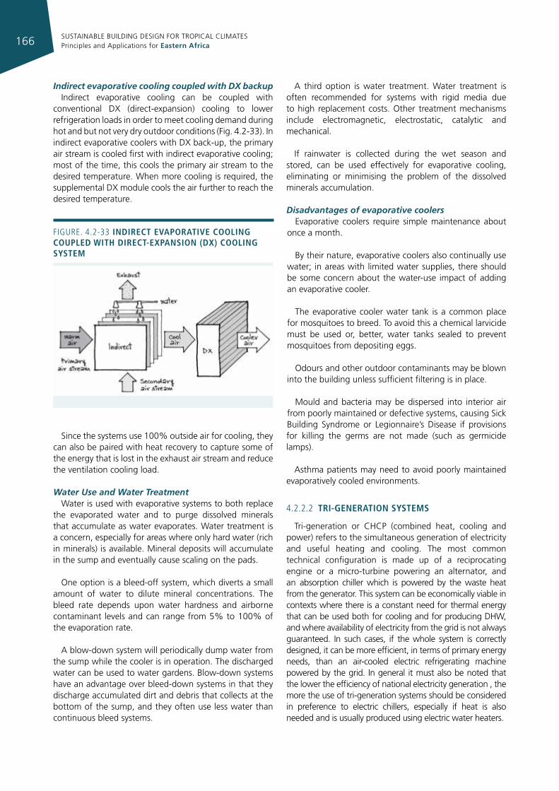
SUSTAINABLE BUILDING DESIGN FOR TROPICAL CLIMATES Principles and Applications for Eastern Africa166
Indirect evaporative cooling coupled with DX backupIndirect evaporative cooling can be coupled with
conventional DX (direct-expansion) cooling to lower refrigeration loads in order to meet cooling demand during hot and but not very dry outdoor conditions (Fig. 4.2-33). In indirect evaporative coolers with DX back-up, the primary air stream is cooled first with indirect evaporative cooling; most of the time, this cools the primary air stream to the desired temperature. When more cooling is required, the supplemental DX module cools the air further to reach the desired temperature.
Since the systems use 100% outside air for cooling, they can also be paired with heat recovery to capture some of the energy that is lost in the exhaust air stream and reduce the ventilation cooling load.
Water Use and Water TreatmentWater is used with evaporative systems to both replace
the evaporated water and to purge dissolved minerals that accumulate as water evaporates. Water treatment is a concern, especially for areas where only hard water (rich in minerals) is available. Mineral deposits will accumulate in the sump and eventually cause scaling on the pads.
One option is a bleed-off system, which diverts a small amount of water to dilute mineral concentrations. The bleed rate depends upon water hardness and airborne contaminant levels and can range from 5% to 100% of the evaporation rate.
A blow-down system will periodically dump water from the sump while the cooler is in operation. The discharged water can be used to water gardens. Blow-down systems have an advantage over bleed-down systems in that they discharge accumulated dirt and debris that collects at the bottom of the sump, and they often use less water than continuous bleed systems.
A third option is water treatment. Water treatment is often recommended for systems with rigid media due to high replacement costs. Other treatment mechanisms include electromagnetic, electrostatic, catalytic and mechanical.
If rainwater is collected during the wet season and stored, can be used effectively for evaporative cooling, eliminating or minimising the problem of the dissolved minerals accumulation.
Disadvantages of evaporative coolersEvaporative coolers require simple maintenance about
once a month.
By their nature, evaporative coolers also continually use water; in areas with limited water supplies, there should be some concern about the water-use impact of adding an evaporative cooler.
The evaporative cooler water tank is a common place for mosquitoes to breed. To avoid this a chemical larvicide must be used or, better, water tanks sealed to prevent mosquitoes from depositing eggs.
Odours and other outdoor contaminants may be blown into the building unless sufficient filtering is in place.
Mould and bacteria may be dispersed into interior air from poorly maintained or defective systems, causing Sick Building Syndrome or Legionnaire’s Disease if provisions for killing the germs are not made (such as germicide lamps).
Asthma patients may need to avoid poorly maintained evaporatively cooled environments.
4.2.2.2 trI-generatIon systems
Tri-generation or CHCP (combined heat, cooling and power) refers to the simultaneous generation of electricity and useful heating and cooling. The most common technical configuration is made up of a reciprocating engine or a micro-turbine powering an alternator, and an absorption chiller which is powered by the waste heat from the generator. This system can be economically viable in contexts where there is a constant need for thermal energy that can be used both for cooling and for producing DHW, and where availability of electricity from the grid is not always guaranteed. In such cases, if the whole system is correctly designed, it can be more efficient, in terms of primary energy needs, than an air-cooled electric refrigerating machine powered by the grid. In general it must also be noted that the lower the efficiency of national electricity generation , the more the use of tri-generation systems should be considered in preference to electric chillers, especially if heat is also needed and is usually produced using electric water heaters.
Figure. 4.2-33 IndIrect evaporatIve coolIng coupled WIth dIrect-expansIon (dx) coolIng system
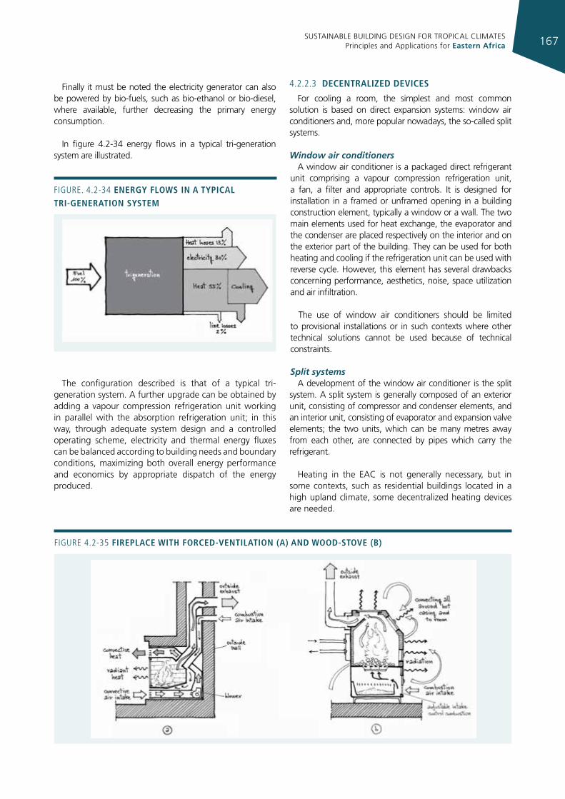
SUSTAINABLE BUILDING DESIGN FOR TROPICAL CLIMATES Principles and Applications for Eastern Africa 167
Finally it must be noted the electricity generator can also be powered by bio-fuels, such as bio-ethanol or bio-diesel, where available, further decreasing the primary energy consumption.
In figure 4.2-34 energy flows in a typical tri-generation system are illustrated.
The configuration described is that of a typical tri-generation system. A further upgrade can be obtained by adding a vapour compression refrigeration unit working in parallel with the absorption refrigeration unit; in this way, through adequate system design and a controlled operating scheme, electricity and thermal energy fluxes can be balanced according to building needs and boundary conditions, maximizing both overall energy performance and economics by appropriate dispatch of the energy produced.
4.2.2.3 decentralIzed devIces
For cooling a room, the simplest and most common solution is based on direct expansion systems: window air conditioners and, more popular nowadays, the so-called split systems.
Window air conditionersA window air conditioner is a packaged direct refrigerant
unit comprising a vapour compression refrigeration unit, a fan, a filter and appropriate controls. It is designed for installation in a framed or unframed opening in a building construction element, typically a window or a wall. The two main elements used for heat exchange, the evaporator and the condenser are placed respectively on the interior and on the exterior part of the building. They can be used for both heating and cooling if the refrigeration unit can be used with reverse cycle. However, this element has several drawbacks concerning performance, aesthetics, noise, space utilization and air infiltration.
The use of window air conditioners should be limited to provisional installations or in such contexts where other technical solutions cannot be used because of technical constraints.
Split systemsA development of the window air conditioner is the split
system. A split system is generally composed of an exterior unit, consisting of compressor and condenser elements, and an interior unit, consisting of evaporator and expansion valve elements; the two units, which can be many metres away from each other, are connected by pipes which carry the refrigerant.
Heating in the EAC is not generally necessary, but in some contexts, such as residential buildings located in a high upland climate, some decentralized heating devices are needed.
Figure. 4.2-34 energy floWs In a typIcal trI-generatIon system
Figure 4.2-35 fIreplace WIth forced-ventIlatIon (a) and Wood-stove (b)
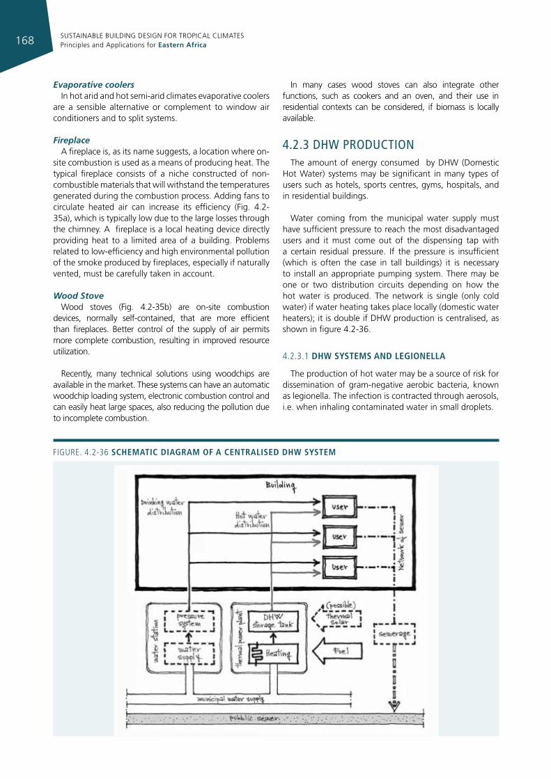
SUSTAINABLE BUILDING DESIGN FOR TROPICAL CLIMATES Principles and Applications for Eastern Africa168
Evaporative coolersIn hot arid and hot semi-arid climates evaporative coolers
are a sensible alternative or complement to window air conditioners and to split systems.
Fireplace A fireplace is, as its name suggests, a location where on-
site combustion is used as a means of producing heat. The typical fireplace consists of a niche constructed of non-combustible materials that will withstand the temperatures generated during the combustion process. Adding fans to circulate heated air can increase its efficiency (Fig. 4.2-35a), which is typically low due to the large losses through the chimney. A fireplace is a local heating device directly providing heat to a limited area of a building. Problems related to low-efficiency and high environmental pollution of the smoke produced by fireplaces, especially if naturally vented, must be carefully taken in account.
Wood StoveWood stoves (Fig. 4.2-35b) are on-site combustion
devices, normally self-contained, that are more efficient than fireplaces. Better control of the supply of air permits more complete combustion, resulting in improved resource utilization.
Recently, many technical solutions using woodchips are available in the market. These systems can have an automatic woodchip loading system, electronic combustion control and can easily heat large spaces, also reducing the pollution due to incomplete combustion.
In many cases wood stoves can also integrate other functions, such as cookers and an oven, and their use in residential contexts can be considered, if biomass is locally available.
4.2.3 dhw producTIonThe amount of energy consumed by DHW (Domestic
Hot Water) systems may be significant in many types of users such as hotels, sports centres, gyms, hospitals, and in residential buildings.
Water coming from the municipal water supply must have sufficient pressure to reach the most disadvantaged users and it must come out of the dispensing tap with a certain residual pressure. If the pressure is insufficient (which is often the case in tall buildings) it is necessary to install an appropriate pumping system. There may be one or two distribution circuits depending on how the hot water is produced. The network is single (only cold water) if water heating takes place locally (domestic water heaters); it is double if DHW production is centralised, as shown in figure 4.2-36.
4.2.3.1 dhW systems and legIonella
The production of hot water may be a source of risk for dissemination of gram-negative aerobic bacteria, known as legionella. The infection is contracted through aerosols, i.e. when inhaling contaminated water in small droplets.
Figure. 4.2-36 schematIc dIagram of a centralIsed dhW system
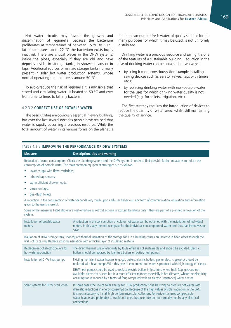
SUSTAINABLE BUILDING DESIGN FOR TROPICAL CLIMATES Principles and Applications for Eastern Africa 169
Hot water circuits may favour the growth and dissemination of legionella, because the bacterium proliferates at temperatures of between 15 °C to 50 °C (at temperatures up to 22 °C the bacterium exists but is inactive). There are critical places in the DHW systems: inside the pipes, especially if they are old and have deposits inside, in storage tanks, in shower heads or in taps. Additional sources of risk are storage tanks normally present in solar hot water production systems, whose normal operating temperature is around 50 °C.
To avoid/reduce the risk of legionella it is advisable that stored and circulating water is heated to 60 °C and over from time to time, to kill any bacteria.
4.2.3.2 correct use of potable Water
The basic utilities are obviously essential in every building, but over the last several decades people have realised that water is rapidly becoming a precious resource. While the total amount of water in its various forms on the planet is
finite, the amount of fresh water, of quality suitable for the many purposes for which it may be used, is not uniformly distributed.
Drinking water is a precious resource and saving it is one of the features of a sustainable building. Reduction in the use of drinking water can be obtained in two ways:
• by using it more consciously (for example installing saving devices such as aerator valves, taps with timers, etc.);
• by replacing drinking water with non-potable water for the uses for which drinking water quality is not needed (e.g. for toilets, irrigation, etc.).
The first strategy requires the introduction of devices to reduce the quantity of water used, whilst still maintaining the quality of service.
measure description, tips and warning
reduction of water consumption Check the plumbing system and the DHW system, in order to find possible further measures to reduce the consumption of potable water. The most common equipment strategies are as follows:
• lavatory taps with flow restrictions;
• infrared tap sensors;
• water efficient shower heads;
• timers on taps;
• dual-flush toilets.
A reduction in the consumption of water depends very much upon end-user behaviour: any form of communication, education and information given to the users is useful.
Some of the measures listed above are cost-effective as retrofit actions in existing buildings only if they are part of a planned renovation of the system.
installation of potable water meters
A reduction in the consumption of cold or hot water can be obtained with the installation of individual meters. in this way the end-user pays for the individual consumption of water and thus has incentives to save.
insulation of DHW storage tank inadequate thermal insulation of the storage tank in a building causes an increase in heat losses through the walls of its casing. replace existing insulation with a thicker layer of insulating material.
replacement of electric boilers for hot water production
The direct thermal use of electricity by Joule effect is not sustainable and should be avoided. electric boilers should be replaced by fuel fired boilers or, better, heat pumps.
installation of DHW heat pumps existing inefficient water heaters (e.g. gas boilers, electric boilers, gas or electric geysers) should be replaced with heat pumps. With this type of equipment hot water is produced with high energy efficiency.
DHW heat pumps could be used to replace electric boilers in locations where fuels (e.g. gas) are not available: electricity is used but in a more efficient manner, especially in hot climates, where the electricity consumption is reduced by a factor of four, compared with an electric (resistance) water heater.
Solar systems for DHW production in some cases the use of solar energy for DHW production is the best way to produce hot water with dramatic reductions in energy consumption. Because of the high values of solar radiation in the eAC, it is not necessary to install high performance solar collectors. For residential uses compact solar water heaters are preferable to traditional ones, because they do not normally require any electrical connections.
TABLe 4.2-2 ImprovIng the performance of dhW systems
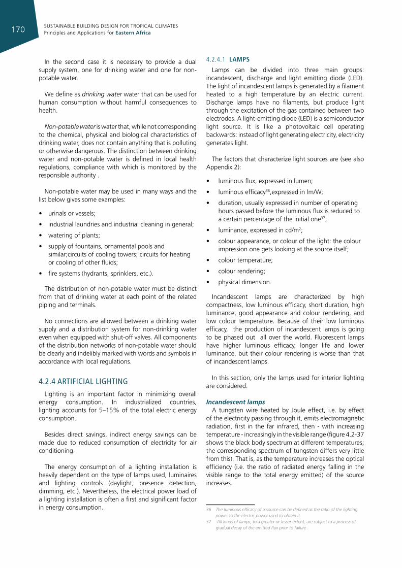
SUSTAINABLE BUILDING DESIGN FOR TROPICAL CLIMATES Principles and Applications for Eastern Africa170
In the second case it is necessary to provide a dual supply system, one for drinking water and one for non-potable water.
We define as drinking water water that can be used for human consumption without harmful consequences to health.
Non-potable water is water that, while not corresponding to the chemical, physical and biological characteristics of drinking water, does not contain anything that is polluting or otherwise dangerous. The distinction between drinking water and non-potable water is defined in local health regulations, compliance with which is monitored by the responsible authority .
Non-potable water may be used in many ways and the list below gives some examples:
• urinals or vessels;
• industrial laundries and industrial cleaning in general;
• watering of plants;
• supply of fountains, ornamental pools and similar;circuits of cooling towers; circuits for heating or cooling of other fluids;
• fire systems (hydrants, sprinklers, etc.).
The distribution of non-potable water must be distinct from that of drinking water at each point of the related piping and terminals.
No connections are allowed between a drinking water supply and a distribution system for non-drinking water even when equipped with shut-off valves. All components of the distribution networks of non-potable water should be clearly and indelibly marked with words and symbols in accordance with local regulations.
4.2.4 arTIfIcIal lIghTIng
Lighting is an important factor in minimizing overall energy consumption. In industrialized countries, lighting accounts for 5–15% of the total electric energy consumption.
Besides direct savings, indirect energy savings can be made due to reduced consumption of electricity for air conditioning.
The energy consumption of a lighting installation is heavily dependent on the type of lamps used, luminaires and lighting controls (daylight, presence detection, dimming, etc.). Nevertheless, the electrical power load of a lighting installation is often a first and significant factor in energy consumption.
4.2.4.1 lamps
Lamps can be divided into three main groups: incandescent, discharge and light emitting diode (LED). The light of incandescent lamps is generated by a filament heated to a high temperature by an electric current. Discharge lamps have no filaments, but produce light through the excitation of the gas contained between two electrodes. A light-emitting diode (LED) is a semiconductor light source. It is like a photovoltaic cell operating backwards: instead of light generating electricity, electricity generates light.
The factors that characterize light sources are (see also Appendix 2):
• luminous flux, expressed in lumen;
• luminous efficacy36,expressed in lm/W;
• duration, usually expressed in number of operating hours passed before the luminous flux is reduced to a certain percentage of the initial one37;
• luminance, expressed in cd/m2;
• colour appearance, or colour of the light: the colour impression one gets looking at the source itself;
• colour temperature;
• colour rendering;
• physical dimension.
Incandescent lamps are characterized by high compactness, low luminous efficacy, short duration, high luminance, good appearance and colour rendering, and low colour temperature. Because of their low luminous efficacy, the production of incandescent lamps is going to be phased out all over the world. Fluorescent lamps have higher luminous efficacy, longer life and lower luminance, but their colour rendering is worse than that of incandescent lamps.
In this section, only the lamps used for interior lighting are considered.
Incandescent lampsA tungsten wire heated by Joule effect, i.e. by effect
of the electricity passing through it, emits electromagnetic radiation, first in the far infrared, then - with increasing temperature - increasingly in the visible range (figure 4.2-37 shows the black body spectrum at different temperatures; the corresponding spectrum of tungsten differs very little from this). That is, as the temperature increases the optical efficiency (i.e. the ratio of radiated energy falling in the visible range to the total energy emitted) of the source increases.
36 The luminous efficacy of a source can be defined as the ratio of the lighting power to the electric power used to obtain it.
37 All kinds of lamps, to a greater or lesser extent, are subject to a process of gradual decay of the emitted flux prior to failure .
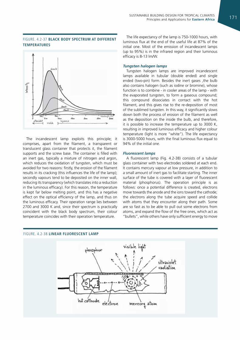
SUSTAINABLE BUILDING DESIGN FOR TROPICAL CLIMATES Principles and Applications for Eastern Africa 171
The incandescent lamp exploits this principle; it comprises, apart from the filament, a transparent or translucent glass container that protects it, the filament supports and the screw base. The container is filled with an inert gas, typically a mixture of nitrogen and argon, which reduces the oxidation of tungsten, which must be avoided for two reasons: firstly, the erosion of the filament results in its cracking (this influences the life of the lamp); secondly vapours tend to be deposited on the inner wall, reducing its transparency (which translates into a reduction in the luminous efficacy). For this reason, the temperature is kept far below melting point, and this has a negative effect on the optical efficiency of the lamp, and thus on the luminous efficacy. Their operation range lies between 2700 and 3000 K and, since their spectrum is practically coincident with the black body spectrum, their colour temperature coincides with their operation temperature.
The life expectancy of the lamp is 750-1000 hours, with luminous flux at the end of the useful life at 87% of the initial one. Most of the emission of incandescent lamps (up to 95%) is in the infrared region and their luminous efficacy is 8-13 lm/W.
Tungsten halogen lampsTungsten halogen lamps are improved incandescent
lamps available in tubular (double ended) and single ended (two-pin) form. Besides the inert gases ,the bulb also contains halogen (such as iodine or bromine), whose function is to combine - in cooler areas of the lamp - with the evaporated tungsten, to form a gaseous compound; this compound dissociates in contact with the hot filament, and this gives rise to the re-deposition of most of the sublimed tungsten. In this way, it significantly slows down both the process of erosion of the filament as well as the deposition on the inside the bulb, and therefore, it is possible to increase the temperature up to 3000 K, resulting in improved luminous efficacy and higher colour temperature (light is more “white”). The life expectancy is 3000-5000 hours, with the final luminous flux equal to 94% of the initial one.
Fluorescent lampsA fluorescent lamp (Fig. 4.2-38) consists of a tubular
glass container with two electrodes soldered at each end. It contains mercury vapour at low pressure, in addition to a small amount of inert gas to facilitate starting. The inner surface of the tube is covered with a layer of fluorescent material (phosphorus). The operation principle is as follows: once a potential difference is created, electrons move towards the anode and the ions toward the cathode; the electrons along the tube acquire speed and collide with atoms that they encounter along their path. Some are so fast as to be able to pull out some electrons from atoms, and expand the flow of the free ones, which act as “bullets”, while others have only sufficient energy to move
Figure. 4.2-37 black body spectrum at dIfferent temperatures
Figure. 4.2-38 lInear fluorescent lamp
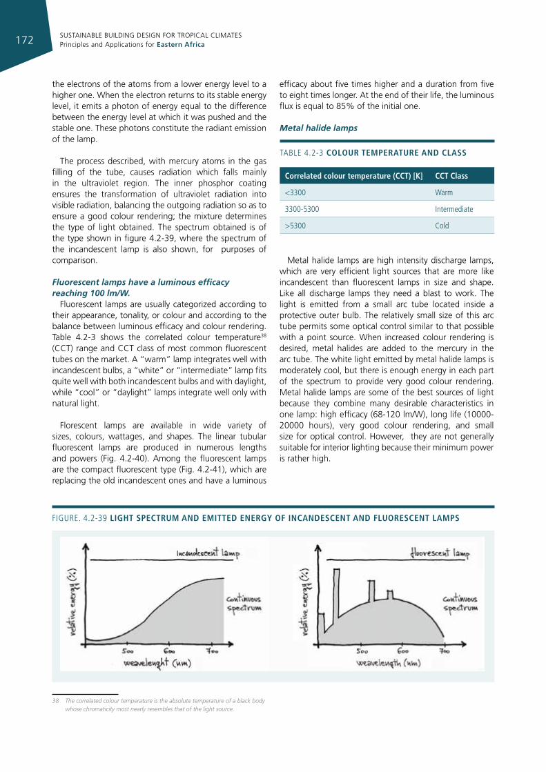
SUSTAINABLE BUILDING DESIGN FOR TROPICAL CLIMATES Principles and Applications for Eastern Africa172
the electrons of the atoms from a lower energy level to a higher one. When the electron returns to its stable energy level, it emits a photon of energy equal to the difference between the energy level at which it was pushed and the stable one. These photons constitute the radiant emission of the lamp.
The process described, with mercury atoms in the gas filling of the tube, causes radiation which falls mainly in the ultraviolet region. The inner phosphor coating ensures the transformation of ultraviolet radiation into visible radiation, balancing the outgoing radiation so as to ensure a good colour rendering; the mixture determines the type of light obtained. The spectrum obtained is of the type shown in figure 4.2-39, where the spectrum of the incandescent lamp is also shown, for purposes of comparison.
Fluorescent lamps have a luminous efficacy reaching 100 lm/W.
Fluorescent lamps are usually categorized according to their appearance, tonality, or colour and according to the balance between luminous efficacy and colour rendering. Table 4.2-3 shows the correlated colour temperature38 (CCT) range and CCT class of most common fluorescent tubes on the market. A “warm” lamp integrates well with incandescent bulbs, a “white” or “intermediate” lamp fits quite well with both incandescent bulbs and with daylight, while “cool” or “daylight” lamps integrate well only with natural light.
Florescent lamps are available in wide variety of sizes, colours, wattages, and shapes. The linear tubular fluorescent lamps are produced in numerous lengths and powers (Fig. 4.2-40). Among the fluorescent lamps are the compact fluorescent type (Fig. 4.2-41), which are replacing the old incandescent ones and have a luminous
38 The correlated colour temperature is the absolute temperature of a black body whose chromaticity most nearly resembles that of the light source.
efficacy about five times higher and a duration from five to eight times longer. At the end of their life, the luminous flux is equal to 85% of the initial one.
Metal halide lamps
Metal halide lamps are high intensity discharge lamps, which are very efficient light sources that are more like incandescent than fluorescent lamps in size and shape. Like all discharge lamps they need a blast to work. The light is emitted from a small arc tube located inside a protective outer bulb. The relatively small size of this arc tube permits some optical control similar to that possible with a point source. When increased colour rendering is desired, metal halides are added to the mercury in the arc tube. The white light emitted by metal halide lamps is moderately cool, but there is enough energy in each part of the spectrum to provide very good colour rendering. Metal halide lamps are some of the best sources of light because they combine many desirable characteristics in one lamp: high efficacy (68-120 lm/W), long life (10000-20000 hours), very good colour rendering, and small size for optical control. However, they are not generally suitable for interior lighting because their minimum power is rather high.
Figure. 4.2-39 lIght spectrum and emItted energy of Incandescent and fluorescent lamps
TABLe 4.2-3 colour temperature and class
correlated colour temperature (cct) [k] cct class
<3300 Warm
3300-5300 intermediate
>5300 Cold
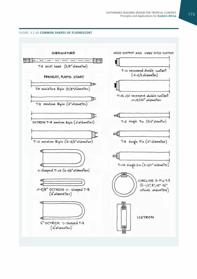
SUSTAINABLE BUILDING DESIGN FOR TROPICAL CLIMATES Principles and Applications for Eastern Africa 173
Figure. 4.2-40 common shapes of fluorescent
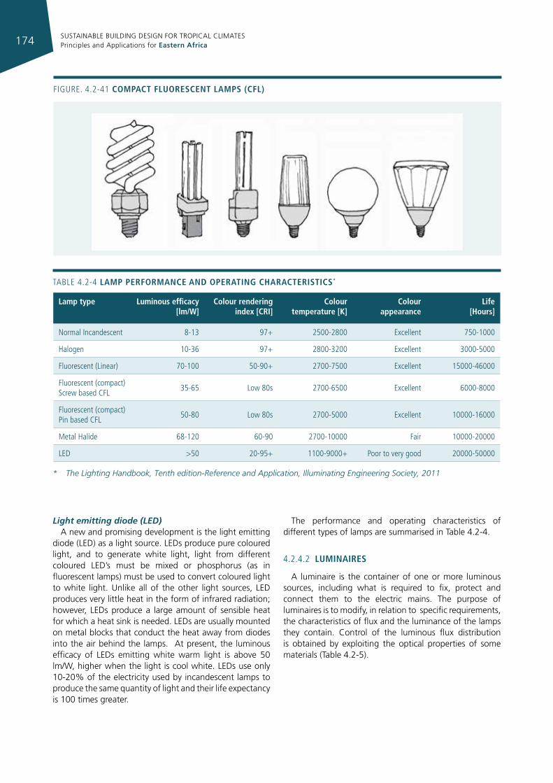
SUSTAINABLE BUILDING DESIGN FOR TROPICAL CLIMATES Principles and Applications for Eastern Africa174
Light emitting diode (LED) A new and promising development is the light emitting
diode (LED) as a light source. LEDs produce pure coloured light, and to generate white light, light from different coloured LED’s must be mixed or phosphorus (as in fluorescent lamps) must be used to convert coloured light to white light. Unlike all of the other light sources, LED produces very little heat in the form of infrared radiation; however, LEDs produce a large amount of sensible heat for which a heat sink is needed. LEDs are usually mounted on metal blocks that conduct the heat away from diodes into the air behind the lamps. At present, the luminous efficacy of LEDs emitting white warm light is above 50 lm/W, higher when the light is cool white. LEDs use only 10-20% of the electricity used by incandescent lamps to produce the same quantity of light and their life expectancy is 100 times greater.
The performance and operating characteristics of different types of lamps are summarised in Table 4.2-4.
4.2.4.2 lumInaIres
A luminaire is the container of one or more luminous sources, including what is required to fix, protect and connect them to the electric mains. The purpose of luminaires is to modify, in relation to specific requirements, the characteristics of flux and the luminance of the lamps they contain. Control of the luminous flux distribution is obtained by exploiting the optical properties of some materials (Table 4.2-5).
Figure. 4.2-41 compact fluorescent lamps (cfl)
* The Lighting Handbook, Tenth edition-Reference and Application, Illuminating Engineering Society, 2011
TABLe 4.2-4 lamp performance and operatIng characterIstIcs*
lamp type luminous efficacy [lm/W]
colour rendering index [crI]
colour temperature [k]
colour appearance
life [hours]
Normal incandescent 8-13 97+ 2500-2800 excellent 750-1000
Halogen 10-36 97+ 2800-3200 excellent 3000-5000
Fluorescent (Linear) 70-100 50-90+ 2700-7500 excellent 15000-46000
Fluorescent (compact) Screw based CFL
35-65 Low 80s 2700-6500 excellent 6000-8000
Fluorescent (compact) Pin based CFL
50-80 Low 80s 2700-5000 excellent 10000-16000
Metal Halide 68-120 60-90 2700-10000 Fair 10000-20000
LeD >50 20-95+ 1100-9000+ Poor to very good 20000-50000
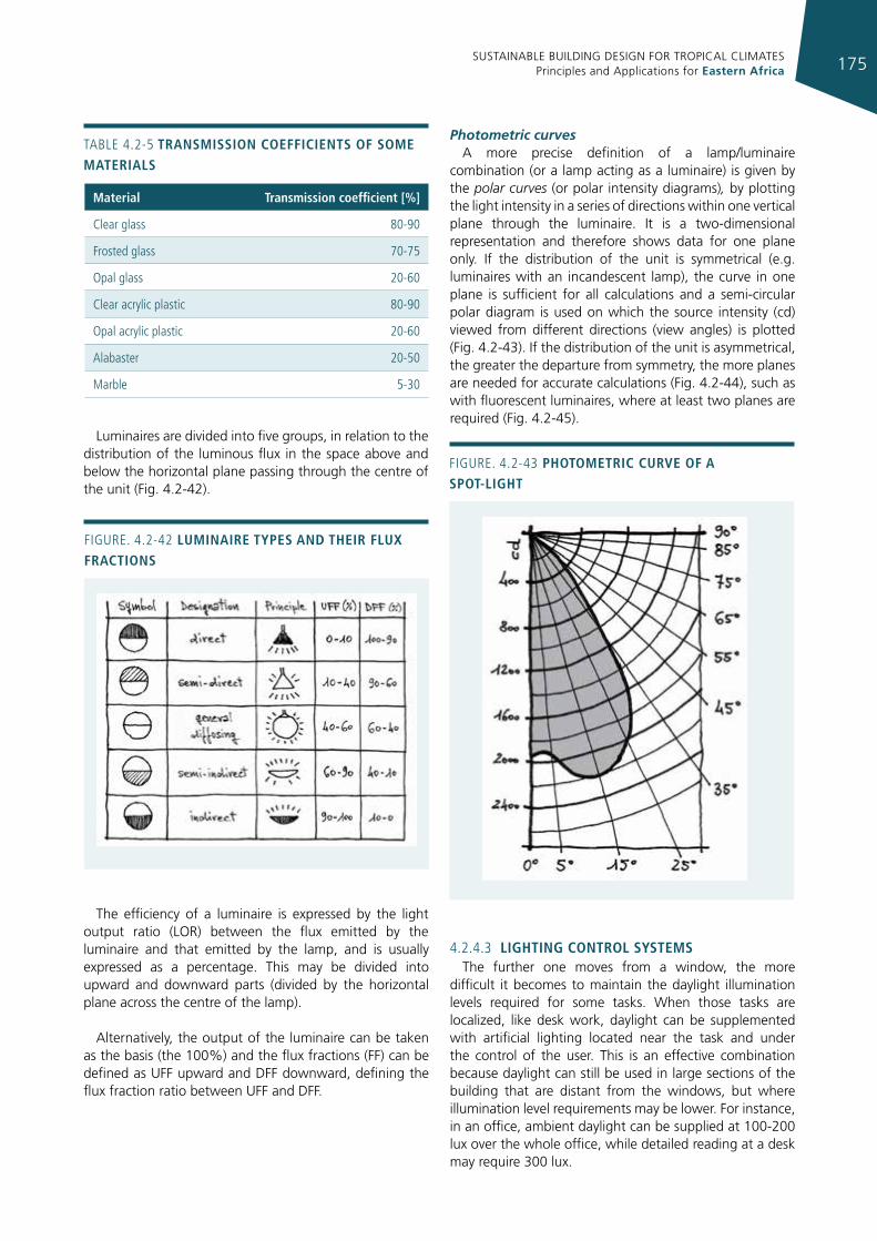
SUSTAINABLE BUILDING DESIGN FOR TROPICAL CLIMATES Principles and Applications for Eastern Africa 175
Luminaires are divided into five groups, in relation to the distribution of the luminous flux in the space above and below the horizontal plane passing through the centre of the unit (Fig. 4.2-42).
The efficiency of a luminaire is expressed by the light output ratio (LOR) between the flux emitted by the luminaire and that emitted by the lamp, and is usually expressed as a percentage. This may be divided into upward and downward parts (divided by the horizontal plane across the centre of the lamp).
Alternatively, the output of the luminaire can be taken as the basis (the 100%) and the flux fractions (FF) can be defined as UFF upward and DFF downward, defining the flux fraction ratio between UFF and DFF.
Photometric curvesA more precise definition of a lamp/luminaire
combination (or a lamp acting as a luminaire) is given by the polar curves (or polar intensity diagrams), by plotting the light intensity in a series of directions within one vertical plane through the luminaire. It is a two-dimensional representation and therefore shows data for one plane only. If the distribution of the unit is symmetrical (e.g. luminaires with an incandescent lamp), the curve in one plane is sufficient for all calculations and a semi-circular polar diagram is used on which the source intensity (cd) viewed from different directions (view angles) is plotted (Fig. 4.2-43). If the distribution of the unit is asymmetrical, the greater the departure from symmetry, the more planes are needed for accurate calculations (Fig. 4.2-44), such as with fluorescent luminaires, where at least two planes are required (Fig. 4.2-45).
4.2.4.3 lIghtIng control systemsThe further one moves from a window, the more
difficult it becomes to maintain the daylight illumination levels required for some tasks. When those tasks are localized, like desk work, daylight can be supplemented with artificial lighting located near the task and under the control of the user. This is an effective combination because daylight can still be used in large sections of the building that are distant from the windows, but where illumination level requirements may be lower. For instance, in an office, ambient daylight can be supplied at 100-200 lux over the whole office, while detailed reading at a desk may require 300 lux.
TABLe 4.2-5 transmIssIon coeffIcIents of some materIals
material transmission coefficient [%]
Clear glass 80-90
Frosted glass 70-75
Opal glass 20-60
Clear acrylic plastic 80-90
Opal acrylic plastic 20-60
Alabaster 20-50
Marble 5-30
Figure. 4.2-42 lumInaIre types and theIr flux fractIons
Figure. 4.2-43 photometrIc curve of a spot-lIght
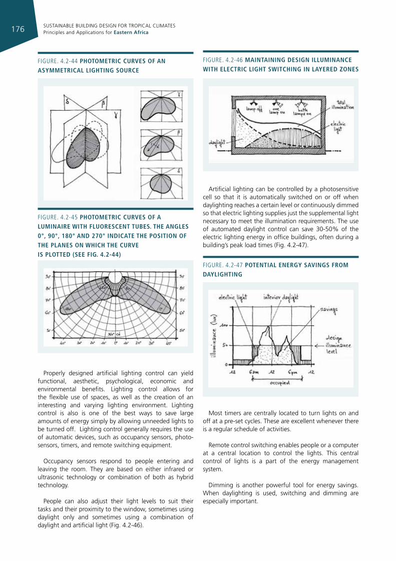
SUSTAINABLE BUILDING DESIGN FOR TROPICAL CLIMATES Principles and Applications for Eastern Africa176
Properly designed artificial lighting control can yield functional, aesthetic, psychological, economic and environmental benefits. Lighting control allows for the flexible use of spaces, as well as the creation of an interesting and varying lighting environment. Lighting control is also is one of the best ways to save large amounts of energy simply by allowing unneeded lights to be turned off. Lighting control generally requires the use of automatic devices, such as occupancy sensors, photo-sensors, timers, and remote switching equipment.
Occupancy sensors respond to people entering and leaving the room. They are based on either infrared or ultrasonic technology or combination of both as hybrid technology.
People can also adjust their light levels to suit their tasks and their proximity to the window, sometimes using daylight only and sometimes using a combination of daylight and artificial light (Fig. 4.2-46).
Artificial lighting can be controlled by a photosensitive cell so that it is automatically switched on or off when daylighting reaches a certain level or continuously dimmed so that electric lighting supplies just the supplemental light necessary to meet the illumination requirements. The use of automated daylight control can save 30-50% of the electric lighting energy in office buildings, often during a building’s peak load times (Fig. 4.2-47).
Most timers are centrally located to turn lights on and off at a pre-set cycles. These are excellent whenever there is a regular schedule of activities.
Remote control switching enables people or a computer at a central location to control the lights. This central control of lights is a part of the energy management system.
Dimming is another powerful tool for energy savings. When daylighting is used, switching and dimming are especially important.
Figure. 4.2-46 maIntaInIng desIgn IllumInance WIth electrIc lIght sWItchIng In layered zones
Figure. 4.2-47 potentIal energy savIngs from daylIghtIng
Figure. 4.2-44 photometrIc curves of an asymmetrIcal lIghtIng source
Figure. 4.2-45 photometrIc curves of a lumInaIre WIth fluorescent tubes. the angles 0°, 90°, 180° and 270° IndIcate the posItIon of the planes on WhIch the curve Is plotted (see fIg. 4.2-44)
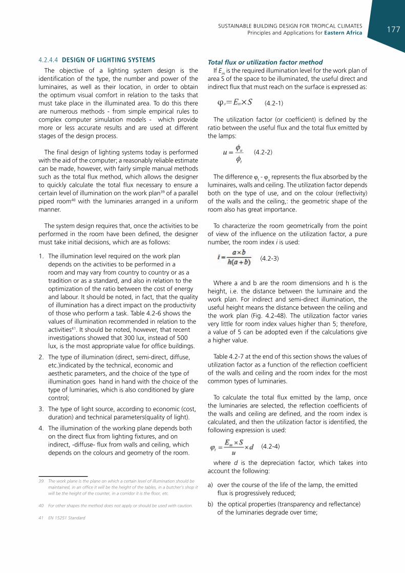
SUSTAINABLE BUILDING DESIGN FOR TROPICAL CLIMATES Principles and Applications for Eastern Africa 177
4.2.4.4 desIgn of lIghtIng systems
The objective of a lighting system design is the identification of the type, the number and power of the luminaires, as well as their location, in order to obtain the optimum visual comfort in relation to the tasks that must take place in the illuminated area. To do this there are numerous methods - from simple empirical rules to complex computer simulation models - which provide more or less accurate results and are used at different stages of the design process.
The final design of lighting systems today is performed with the aid of the computer; a reasonably reliable estimate can be made, however, with fairly simple manual methods such as the total flux method, which allows the designer to quickly calculate the total flux necessary to ensure a certain level of illumination on the work plan39 of a parallel piped room40 with the luminaries arranged in a uniform manner.
The system design requires that, once the activities to be performed in the room have been defined, the designer must take initial decisions, which are as follows:
1. The illumination level required on the work plan depends on the activities to be performed in a room and may vary from country to country or as a tradition or as a standard, and also in relation to the optimization of the ratio between the cost of energy and labour. It should be noted, in fact, that the quality of illumination has a direct impact on the productivity of those who perform a task. Table 4.2-6 shows the values of illumination recommended in relation to the activities41. It should be noted, however, that recent investigations showed that 300 lux, instead of 500 lux, is the most appropriate value for office buildings.
2. The type of illumination (direct, semi-direct, diffuse, etc.)indicated by the technical, economic and aesthetic parameters, and the choice of the type of illumination goes hand in hand with the choice of the type of luminaries, which is also conditioned by glare control;
3. The type of light source, according to economic (cost, duration) and technical parameters(quality of light).
4. The illumination of the working plane depends both on the direct flux from lighting fixtures, and on indirect, -diffuse- flux from walls and ceiling, which depends on the colours and geometry of the room.
39 The work plane is the plane on which a certain level of illumination should be maintained, in an office it will be the height of the tables, in a butcher’s shop it will be the height of the counter, in a corridor it is the floor, etc.
40 For other shapes the method does not apply or should be used with caution.
41 EN 15251 Standard
Total flux or utilization factor methodIf Em is the required illumination level for the work plan of
area S of the space to be illuminated, the useful direct and indirect flux that must reach on the surface is expressed as:
(4.2-1)
The utilization factor (or coefficient) is defined by the ratio between the useful flux and the total flux emitted by the lamps:
(4.2-2)
The difference φt - φu represents the flux absorbed by the luminaires, walls and ceiling. The utilization factor depends both on the type of use, and on the colour (reflectivity) of the walls and the ceiling,: the geometric shape of the room also has great importance.
To characterize the room geometrically from the point of view of the influence on the utilization factor, a pure number, the room index i is used:
(4.2-3)
Where a and b are the room dimensions and h is the height, i.e. the distance between the luminaire and the work plan. For indirect and semi-direct illumination, the useful height means the distance between the ceiling and the work plan (Fig. 4.2-48). The utilization factor varies very little for room index values higher than 5; therefore, a value of 5 can be adopted even if the calculations give a higher value.
Table 4.2-7 at the end of this section shows the values of utilization factor as a function of the reflection coefficient of the walls and ceiling and the room index for the most common types of luminaries.
To calculate the total flux emitted by the lamp, once the luminaries are selected, the reflection coefficients of the walls and ceiling are defined, and the room index is calculated, and then the utilization factor is identified, the following expression is used:
(4.2-4)
where d is the depreciation factor, which takes into account the following:
a) over the course of the life of the lamp, the emitted flux is progressively reduced;
b) the optical properties (transparency and reflectance) of the luminaries degrade over time;
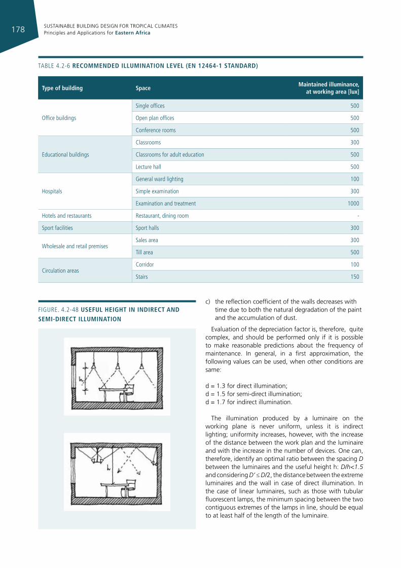
SUSTAINABLE BUILDING DESIGN FOR TROPICAL CLIMATES Principles and Applications for Eastern Africa178
c) the reflection coefficient of the walls decreases with time due to both the natural degradation of the paint and the accumulation of dust.
Evaluation of the depreciation factor is, therefore, quite complex, and should be performed only if it is possible to make reasonable predictions about the frequency of maintenance. In general, in a first approximation, the following values can be used, when other conditions are same:
d = 1.3 for direct illumination; d = 1.5 for semi-direct illumination; d = 1.7 for indirect illumination.
The illumination produced by a luminaire on the working plane is never uniform, unless it is indirect lighting; uniformity increases, however, with the increase of the distance between the work plan and the luminaire and with the increase in the number of devices. One can, therefore, identify an optimal ratio between the spacing D between the luminaires and the useful height h: D/h<1.5 and considering D’ ≤ D/2, the distance between the extreme luminaires and the wall in case of direct illumination. In the case of linear luminaires, such as those with tubular fluorescent lamps, the minimum spacing between the two contiguous extremes of the lamps in line, should be equal to at least half of the length of the luminaire.
Figure. 4.2-48 useful heIght In IndIrect and semI-dIrect IllumInatIon
type of building spacemaintained illuminance,
at working area [lux]
Office buildings
Single offices 500
Open plan offices 500
Conference rooms 500
educational buildings
Classrooms 300
Classrooms for adult education 500
Lecture hall 500
Hospitals
general ward lighting 100
Simple examination 300
examination and treatment 1000
Hotels and restaurants restaurant, dining room -
Sport facilities Sport halls 300
Wholesale and retail premisesSales area 300
Till area 500
Circulation areasCorridor 100
Stairs 150
TABLe 4.2-6 recommended IllumInatIon level (en 12464-1 standard)
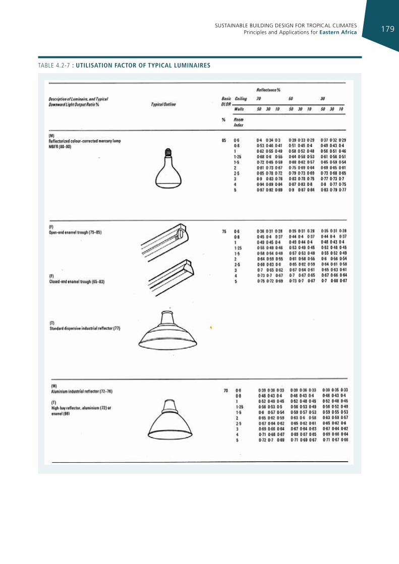
SUSTAINABLE BUILDING DESIGN FOR TROPICAL CLIMATES Principles and Applications for Eastern Africa 179
TABLe 4.2-7 : utIlIsatIon factor of typIcal lumInaIres
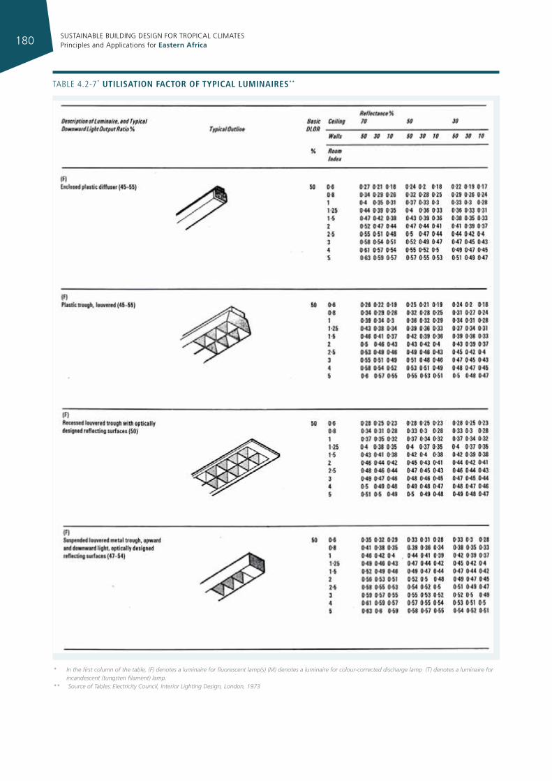
SUSTAINABLE BUILDING DESIGN FOR TROPICAL CLIMATES Principles and Applications for Eastern Africa180
* In the first column of the table, (F) denotes a luminaire for fluorescent lamp(s) (M) denotes a luminaire for colour-corrected discharge lamp (T) denotes a luminaire for incandescent (tungsten filament) lamp.
** Source of Tables: Electricity Council, Interior Lighting Design, London, 1973
TABLe 4.2-7* utIlIsatIon factor of typIcal lumInaIres**
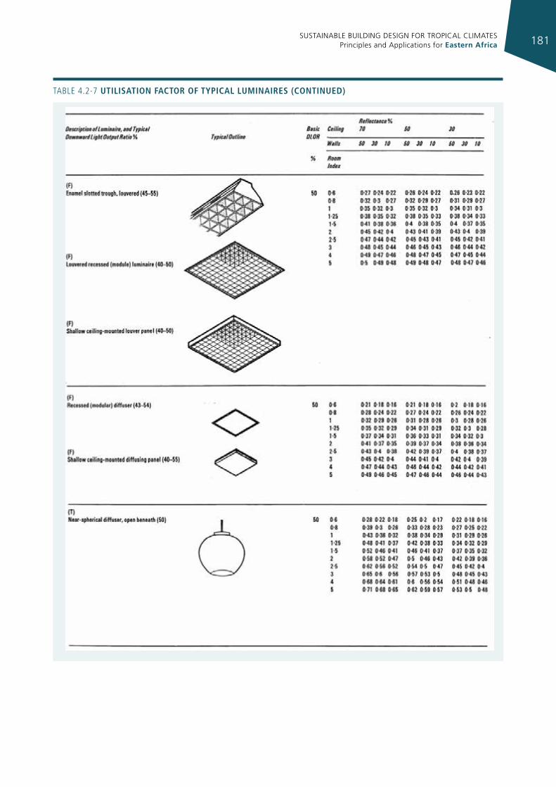
SUSTAINABLE BUILDING DESIGN FOR TROPICAL CLIMATES Principles and Applications for Eastern Africa 181
TABLe 4.2-7 utIlIsatIon factor of typIcal lumInaIres (contInued)
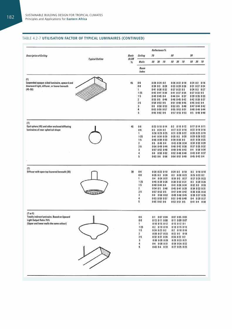
SUSTAINABLE BUILDING DESIGN FOR TROPICAL CLIMATES Principles and Applications for Eastern Africa182
TABLe 4.2-7 utIlIsatIon factor of typIcal lumInaIres (contInued)
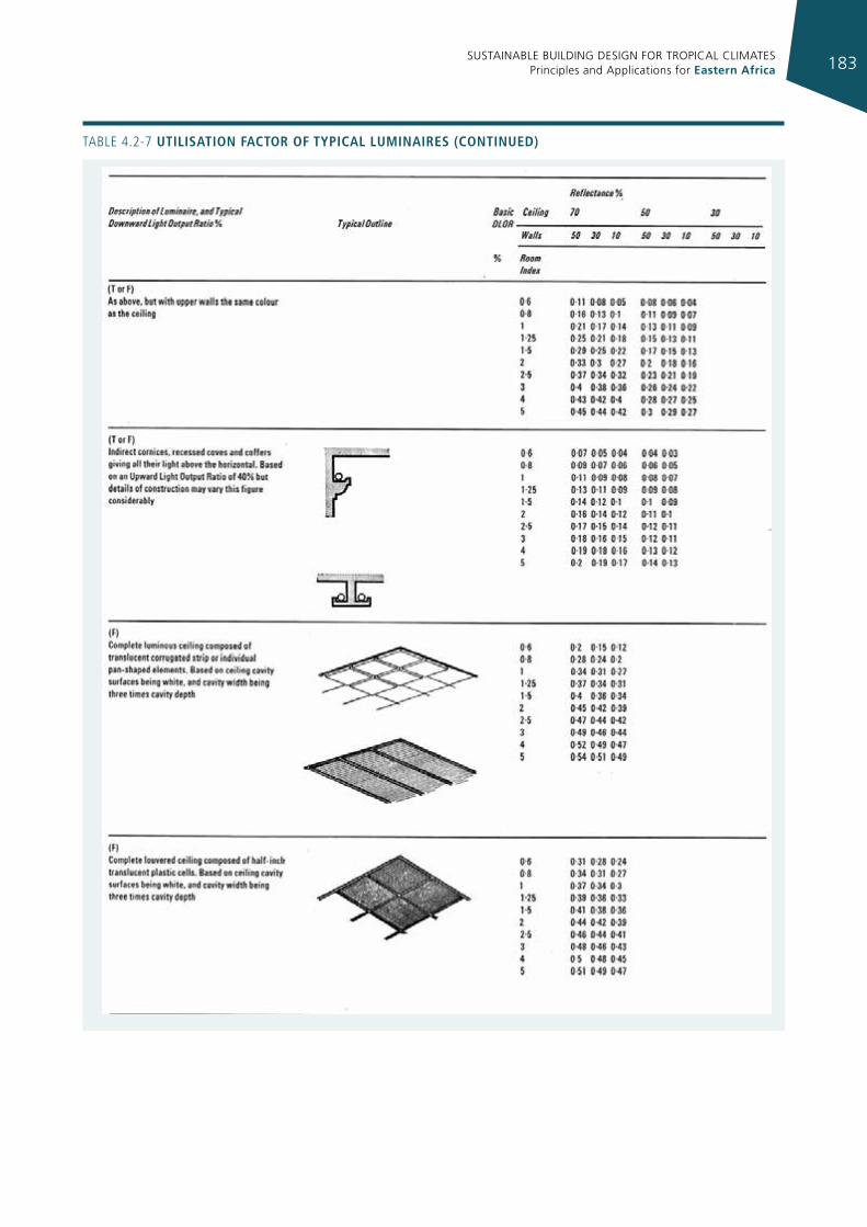
SUSTAINABLE BUILDING DESIGN FOR TROPICAL CLIMATES Principles and Applications for Eastern Africa 183
TABLe 4.2-7 utIlIsatIon factor of typIcal lumInaIres (contInued)
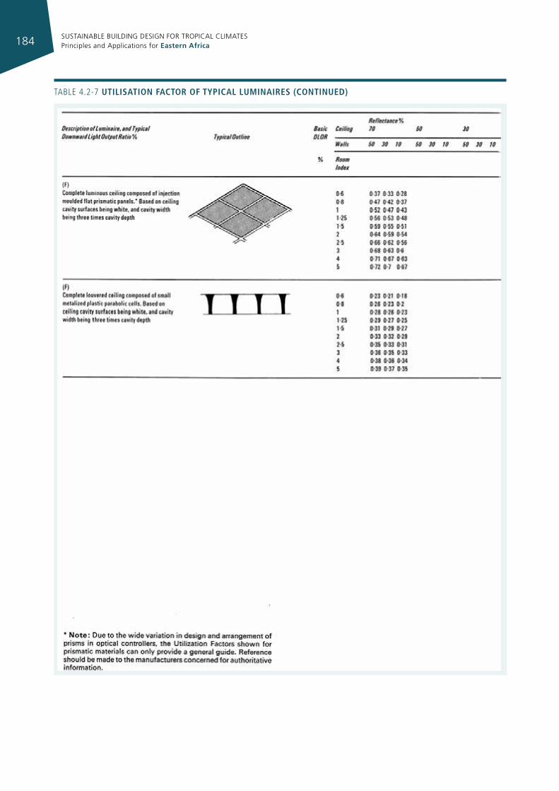
SUSTAINABLE BUILDING DESIGN FOR TROPICAL CLIMATES Principles and Applications for Eastern Africa184
TABLe 4.2-7 utIlIsatIon factor of typIcal lumInaIres (contInued)
SUSTAINABLE BUILDING DESIGN FOR TROPICAL CLIMATES Principles and Applications for Eastern Africa 185
Determining the number and power of luminaires, using the lumen method of calculation
With the use of a simple nomogram42, as shown in figure 4.2-49, the number and power of luminaries required in a lighting system design can be calculated. The procedure is as follows43:
1. Establish the Room Index (can be calculated by the expression defined in previous section);
2. With this Room Index, look up the Utilization Factor for the type of luminaire to be used (Table 4.2-7). Mark the UF on Scale 8;
3. Mark the room length on Scale 1 and room width on Scale 2. Draw a line through these points to cut Scale 3;
4. From this point on Scale 3 draw a line through the required illuminance on Scale 4 to cut Scale 5;
5. From this point on Scale 5 draw a line through the mark on Scale 8 to cut Scale 9. This gives the total light flux to be provided by all the lamps;
6. A line drawn from the point on Scale 9 through an appropriate point (number of luminaires) on Scale 10 will cut Scale 11 at the number of lamp lumens required per luminaire. Alternatively, if the lumen output of lamps per luminaire is known, a line between the point on Scale 9 and the appropriate point on Scale 11 will cut Scale 10 at the number of luminaires required;
7. The last two columns on the right give an approximate indication of suitable lamp combinations per luminaire to give the light output required.
4.2.4.8 tIps for artIfIcIal lIghtIngIn order to minimise energy consumption, the integration
of daylighting and artificial lighting should be considered from the early stages of the building design process. Lighting strategy, fixture selection, and control methods are all affected by the goal of daylight integration.
Daylighting can provide the required ambient lighting for most operating hours. User-controllable task lights should be provided to ensure that task illumination requirements are met at all locations when supplemental lighting is necessary.
42 Electricity Council, Interior Lighting Design, London, 197343 Note: When using this nomogram in conjunction with the tables of Utilization
Factors first enter, on Scale 8, the UF obtained from the tables. If the Downward Light Output Ratio of the luminaire to be used is the same as the Basic DLOR given in these tables ignore Scales 6 and 7.
If the DLOR of the luminaire to be used differs significantly from that listed in the tables, enter the figures given in the table on Scale 7. Draw a line from this point on Scale 7 through the UF (from the tables) on Scale 8 and produce to cut Scale 6. The intersection on Scale 6 then gives the utilance of the luminaire. From the utilance on Scale 6 draw a line through the actual downward light output ratio of the luminaire to be used on Scale 7. The intersection of this line with Scale 8 gives the corrected Utilization Factor which is then used to complete the calculation.
Users near windows will often use daylight as their primary task source. In general, ambient illumination levels should be significantly less than task levels (but not less than 1/3 of task levels).
Indirect lighting, often most appreciated by architects because of the visual atmosphere it produces, should be used very carefully: it is very inefficient from the point of view of energy consumption. It is better to use luminaires providing semi-direct illumination with UFF < 20%: this is a good compromise between energy efficiency and visual pleasantness.
Lamps• Use fluorescent lamps and dimming ballasts.
Fluorescent lighting is appropriate for both dimming and switching applications, because it can be efficiently dimmed over a wide range without changes in colour and can be turned on and off virtually instantaneously. Most dimming fluorescent ballasts dim to 10-20% light output, but “architectural” dimmers dim to 1% (these dimmers come at a cost premium).
• Consider the possibility of using LED sources, especially for task lighting. Even though they are more expensive, they are dimmable and have a very long life-span.
• If daylight and artificial light are used at the same time (i.e. daylighting is insufficient all the time and must be complemented with artificial lighting), try to match the cool colour temperature of daylight. For best colour temperature pairing with daylight, specify the use of fluorescent lamps with a colour temperature of 4000 K. If, however, daylighting is sufficient most of the time, and artificial lighting is needed only at night, choose fluorescent lamps with colour temperature 2700-3000 K.
• Avoid high-intensity discharge lamps. Most HID sources (metal halide, high pressure sodium and mercury vapour) are not appropriate for dimming applications because they undergo colour shifts as they dim and have a more limited dimming range.
• Choose energy-efficient hardware. No matter what the lighting strategy, always choose the most cost-effective lighting technologies and the most effective controls available within the design budget.
Lighting control• Choose dimming hardware if daylighting, lumen
maintenance, or tuning are the selected control strategies. With the cost of dimming ballasts still high but falling, dimming control is at least twice as expensive as switching control but it is the best for implementing these strategies.
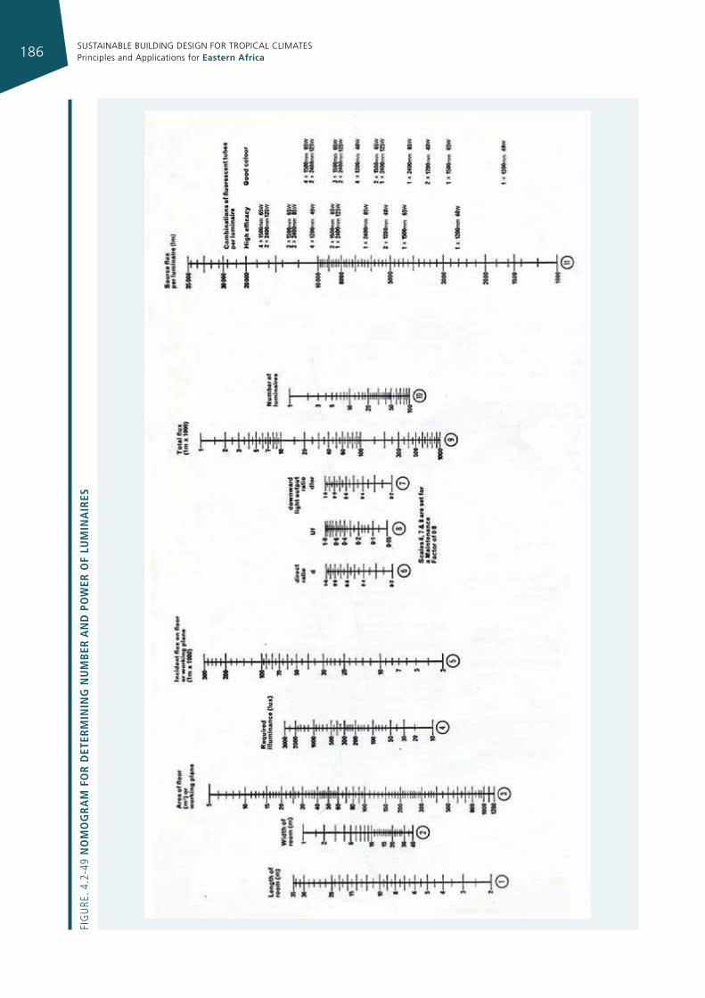
SUSTAINABLE BUILDING DESIGN FOR TROPICAL CLIMATES Principles and Applications for Eastern Africa186
Fig
ure
. 4.2
-49
no
mo
gr
am
fo
r d
eter
mIn
Ing
nu
mb
er a
nd
po
Wer
of
lum
Ina
Ires
SUSTAINABLE BUILDING DESIGN FOR TROPICAL CLIMATES Principles and Applications for Eastern Africa 187
• For all other strategies, choose switching hardware since switching technologies are inexpensive, have a short payback period, and typically do not require special expertise to install.
• Use programmable time controls for a more sophisticated form of scheduling control than simple time clocks.
• Use occupancy sensors. These are easily installed in wall boxes in lieu of manual switches.
Visual Comfort• Keep ambient lighting low for computer screens. If
computers are present, ambient lighting should not exceed 300 lux. A rule of thumb for spaces with video display terminals (VDTs) is to provide as little light as possible on computer screens, 150-300 lux for surround lighting.
• Keep lamp reflectance out of computer screens. Limit the potential for reflected glare from ceiling lights in computer screens.
• Avoid brightness glare from exposed lamps in the field of view. Obstruct direct views of light sources to avoid glare. Direct/indirect lighting is one method of doing this.
• Use lighting strategies to balance window glare if anticipated. Keep luminance of the interior environment high to balance window brightness if there are no architectural modifiers such as deep reveals, shading devices or elements to filter daylight. A light wall or ceiling wash towards the back of the space (farthest area from window) is generally effective. A small increase in energy use for this purpose is acceptable.
Integration Issues• Location of the windows directly influences lighting
control strategies and placement of photocell sensors.
• Quality of the perimeter spaces depends on blending and balance between daylight (a strongly directional light from the side providing high illumination and cool colour) and the very different nature of electric lighting.
• Interior surfaces, and especially the ceiling, must be light coloured.
• Coordinate workstations with window placement and fixture locations, especially for glare-sensitive workspaces (e.g., computers). Align view direction of VDT parallel to the window wall.
• Locations of partitions and other tall furniture should not interfere with penetration of daylight. This may require re-orienting partitions or using translucent panels rather than opaque.
• Lighting designer should supply a reasonable estimation of lighting power reduction due to daylight controls for the purpose of cooling load calculations. Expect the perimeter zones to have less than peak electric lighting loads at peak cooling periods (e.g., summer noon).
• Incorporating a daylighting strategy does not have a negative effect on lighting design. In fact, lighting quality is typically higher in a carefully daylit space.
• Direct/indirect systems using pendant fixtures are typically a 50% cost premium over direct lighting fixtures.
• Many efficient lighting technologies have short paybacks and often qualify for utility rebates or incentives, due to the very large percentage of building energy use consumed by lighting. Costs of some newer technologies (e.g., dimmable electronic ballasts) are falling rapidly with time. Be sure to use current cost estimates in your analysis.
4.2.5 hvac desIgn, commIssIonIng, operaTIon and maInTenance guIdelInes
One of the primary tasks for an architect is to create a built environment that is able to improve human well-being and productivity, at the same time maintaining an adequate level of operational efficiency and an effective use of natural resources.
The HVAC system is one of the most important elements in designing a “sustainable” building. First of all it is necessary to define the objectives and criteria of the design process itself because good results cannot be achieved without clear goals. A conventional design approach is, by itself, not sufficient to achieve good performance because a building should be conceived as a system, capable of providing different types of services with the minimum impact. In fact, the incorrect design of a building from the architectural point of view (envelope, orientation, lay-out of the internal space, etc.) can result, for example, in an oversized HVAC system which can be energy intensive to operate and costly and difficult to maintain.
Subsequently, in the commissioning process, the objectives, criteria and basis of design have to be documented and verified, giving a clear direction for the project during the construction phase, and a benchmark for performance comparison and evaluation in the measurement and testing phase.
Finally, operation and maintenance (O&M) play a key role in maintaining a high energy performance and an adequate level of service for the building during its lifetime, thus helping to achieve the expected results on a long-term basis.
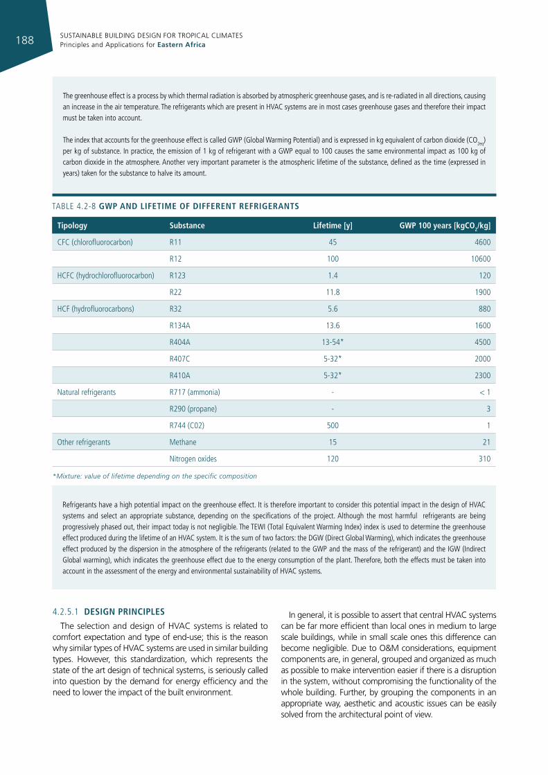
SUSTAINABLE BUILDING DESIGN FOR TROPICAL CLIMATES Principles and Applications for Eastern Africa188
The greenhouse effect is a process by which thermal radiation is absorbed by atmospheric greenhouse gases, and is re-radiated in all directions, causing an increase in the air temperature. The refrigerants which are present in HVAC systems are in most cases greenhouse gases and therefore their impact must be taken into account.
The index that accounts for the greenhouse effect is called gWP (global Warming Potential) and is expressed in kg equivalent of carbon dioxide (CO2eq) per kg of substance. in practice, the emission of 1 kg of refrigerant with a gWP equal to 100 causes the same environmental impact as 100 kg of carbon dioxide in the atmosphere. Another very important parameter is the atmospheric lifetime of the substance, defined as the time (expressed in years) taken for the substance to halve its amount.
TABLe 4.2-8 gWp and lIfetIme of dIfferent refrIgerants
tipology substance lifetime [y] gWp 100 years [kgco2/kg]
CFC (chlorofluorocarbon) r11 45 4600
r12 100 10600
HCFC (hydrochlorofluorocarbon) r123 1.4 120
r22 11.8 1900
HCF (hydrofluorocarbons) r32 5.6 880
r134A 13.6 1600
r404A 13-54* 4500
r407C 5-32* 2000
r410A 5-32* 2300
Natural refrigerants r717 (ammonia) - < 1
r290 (propane) - 3
r744 (C02) 500 1
Other refrigerants Methane 15 21
Nitrogen oxides 120 310
*Mixture: value of lifetime depending on the specific composition
refrigerants have a high potential impact on the greenhouse effect. it is therefore important to consider this potential impact in the design of HVAC systems and select an appropriate substance, depending on the specifications of the project. Although the most harmful refrigerants are being progressively phased out, their impact today is not negligible. The TeWi (Total equivalent Warming index) index is used to determine the greenhouse effect produced during the lifetime of an HVAC system. it is the sum of two factors: the DgW (Direct global Warming), which indicates the greenhouse effect produced by the dispersion in the atmosphere of the refrigerants (related to the gWP and the mass of the refrigerant) and the igW (indirect global warming), which indicates the greenhouse effect due to the energy consumption of the plant. Therefore, both the effects must be taken into account in the assessment of the energy and environmental sustainability of HVAC systems.
4.2.5.1 desIgn prIncIples
The selection and design of HVAC systems is related to comfort expectation and type of end-use; this is the reason why similar types of HVAC systems are used in similar building types. However, this standardization, which represents the state of the art design of technical systems, is seriously called into question by the demand for energy efficiency and the need to lower the impact of the built environment.
In general, it is possible to assert that central HVAC systems can be far more efficient than local ones in medium to large scale buildings, while in small scale ones this difference can become negligible. Due to O&M considerations, equipment components are, in general, grouped and organized as much as possible to make intervention easier if there is a disruption in the system, without compromising the functionality of the whole building. Further, by grouping the components in an appropriate way, aesthetic and acoustic issues can be easily solved from the architectural point of view.
SUSTAINABLE BUILDING DESIGN FOR TROPICAL CLIMATES Principles and Applications for Eastern Africa 189
Further, central systems offer the possibility of exploiting economies of scale. Larger capacity heating and cooling technologies have higher efficiencies and lower specific costs (cost per unit of power installed), thus reducing the overall investment and O&M costs. If a building is operated in a constant way over time with similar comfort requirements and end-uses, a centralized system is usually the best choice. However, in this case there can also be some drawbacks; for example, an efficient centralized energy management scheme must be correctly tuned for multi-zone operation. Of course, the analysis of performance and operational strategies for optimization are less intuitive than for small, local systems.
In general, appropriate sizing of HVAC components is key to obtaining energy-efficient systems. Oversized systems obviously have higher installation costs, and also typically operate in a less efficient way at part-load conditions and have a shorter life because of frequent ON/OFF cycles. For these reasons, in the detailed design phase, when building architecture and envelope configuration are precisely defined, accurate calculations of cooling loads must be performed without introducing excessive safety margins.
More generally, some useful indications with respect to high-efficiency HVAC design are reported below:
• use multiple equipment components so that each one operates close to full load in every working condition (modulation of power), or use components that reduce power requirements as the load decreases. For example, select multiple chillers of different sizes instead of one large chiller, select a multi-compressor chiller instead of a single compressor chiller, select a multi-stage compressor instead of a single-stage compressor or select variable-speed motors instead of constant-speed motors;
• use VAV-type or VRF-type AC systems if possible, as long as they are typically the most energy efficient solutions, and avoid terminal reheating systems unless the reheating energy comes from waste energy (hot water from solar or CHP technologies);
• when sizing packaged systems, make sure that latent cooling capacity is also adequate in low cooling-load conditions;
• design zone air flow must meet both temperature and humidity requirements in different boundary conditions; the zone cooling and dehumidification needs at both design and off-design conditions must be considered particularly when determining the design air flow and supply temperature.
• provide technologies and controls to continuously adjust the ventilation rate for spaces with varying occupancy to prevent unnecessary cooling of large quantities of outside air (for example CO
2 sensors);
• provide automatic time-controlled or load-controlled auxiliary electric appliances, such as fans or pumps, and automatic temperature setback in order to minimize wasted energy;
• select fans and pumps taking into consideration their type, efficiency and noise level;
• pre-arrange an energy monitoring system and, if suitable, a building automation system to ease analysis and control;
• avoid downsizing air ducts and pipes as it will increase pressure drop, thereby requiring fans, pumps and motors to be oversized;
• select heat pump water heating systems in spaces such as restaurants, commercial buildings and hotels in which it is possible to take advantage of the space cooling opportunity provided by the system and avoid long DHW circuits, and also in contexts where there is limited DHW demand (household context).
4.2.5.2 summary of hvac systems features
In the following tables, the most important features of the different HVAC system types are summarized, and the presence or the absence of some characteristics or the degree of quality of their performance with respect to the different indicators are described.
In the following table the energy conversion systems are described, along with the fuel and energy sources used, the building services guaranteed and the main pros and cons.
Yes = the function can be fulfilled by the system/device;
no = the function cannot be fulfilled by the system/device;
Yes*= the function is not always present in all commercial products.
Low/medium/high = level of performance or ability to control a parameter that can be achieved by the system/device.
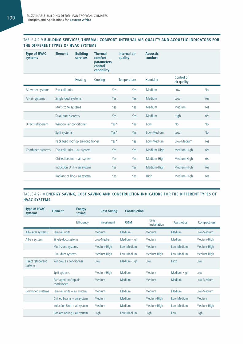
SUSTAINABLE BUILDING DESIGN FOR TROPICAL CLIMATES Principles and Applications for Eastern Africa190
All-water systems Fan-coil units Yes Yes Medium Low No
All-air systems Single-duct systems Yes Yes Medium Low Yes
Multi-zone systems Yes Yes Medium Medium Yes
Dual-duct systems Yes Yes Medium High Yes
Direct refrigerant Window air conditioner Yes* Yes Low No No
Split systems Yes* Yes Low-Medium Low No
Packaged rooftop air-conditioner Yes* Yes Low-Medium Low-Medium Yes
Combined systems Fan-coil units + air system Yes Yes Medium-High Medium-High Yes
Chilled beams + air system Yes Yes Medium-High Medium-High Yes
induction unit + air system Yes Yes Medium-High Medium-High Yes
radiant ceiling+ air system Yes Yes High Medium-High Yes
type of hvac systems
element building services
thermal comfort parameters control capability
Internal air quality
acoustic comfort
heating cooling Temperature humidity control of air quality
TABLe 4.2-9 buIldIng servIces, thermal comfort, Internal aIr qualIty and acoustIc IndIcators for the dIfferent types of hvac systems
All-water systems Fan-coil units Medium Medium Medium Medium Low-Medium
All-air system Single-duct systems Low-Medium Medium-High Medium Medium Medium-High
Multi-zone systems Medium-High Low-Medium Medium Low-Medium Medium-High
Dual-duct systems Medium-High Low-Medium Medium-High Low-Medium Medium-High
Direct refrigerant systems
Window air conditioner Low Medium-High Low High Low
Split systems Medium-High Medium Medium Medium-High Low
Packaged rooftop air-conditioner
Medium Medium Medium Medium Low-Medium
Combined systems Fan-coil units + air system Medium Medium Medium Medium Low-Medium
Chilled beams + air system Medium Medium Medium-High Low-Medium Medium
induction unit + air system Medium Medium Medium-High Low-Medium Medium-High
radiant ceiling+ air system High Low-Medium High Low High
type of hvac systems
elementenergy saving
cost saving construction
efficiency Investment o&m easy installation
aesthetics compactness
TABLe 4.2-10 energy savIng, cost savIng and constructIon IndIcators for the dIfferent types of hvac systems
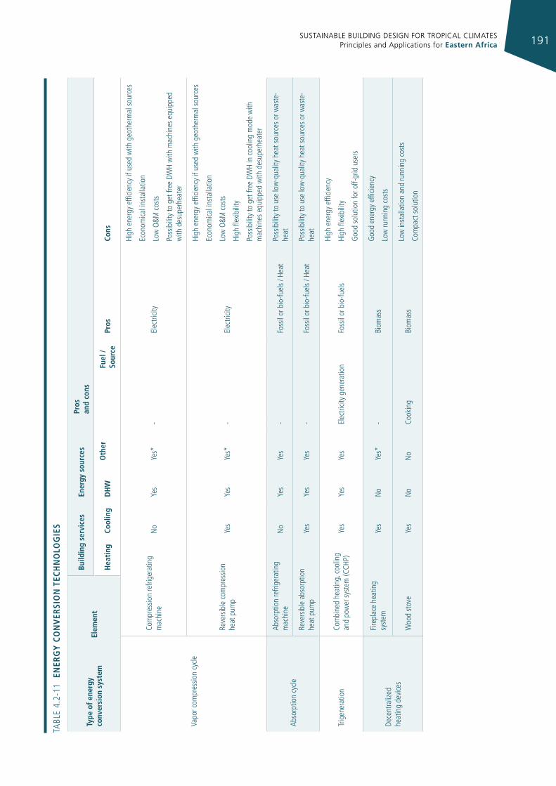
SUSTAINABLE BUILDING DESIGN FOR TROPICAL CLIMATES Principles and Applications for Eastern Africa 191
type
of e
nerg
y co
nver
sion
sys
tem
elem
ent
build
ing
serv
ices
ener
gy s
ourc
espr
os
and
cons
hea
ting
cool
ing
dh
Wo
ther
fuel
/ so
urce
pros
cons
V apo
r com
pres
sion
cycle
Com
pres
sion
refri
gera
ting
mac
hine
N
oYe
sYe
s*-
elec
tricit
y
High
ene
rgy
effic
ienc
y if
used
with
geo
ther
mal
sou
rces
econ
omica
l ins
talla
tion
Low
O&M
cos
ts
P oss
ibili
ty to
get
free
DW
H w
ith m
achi
nes
equi
pped
w
ith d
esup
erhe
ater
reve
rsib
le c
ompr
essio
n
heat
pum
pYe
sYe
sYe
s*-
elec
tricit
y
High
ene
rgy
effic
ienc
y if
used
with
geo
ther
mal
sou
rces
econ
omica
l ins
talla
tion
Low
O&M
cos
ts
High
flex
ibili
ty
Poss
ibili
ty to
get
free
DW
H in
coo
ling
mod
e w
ith
mac
hine
s eq
uipp
ed w
ith d
esup
erhe
ater
Abso
rptio
n cy
cle
Abso
rptio
n re
frige
ratin
g m
achi
ne
No
Yes
Yes
-Fo
ssil
or b
io-fu
els
/ Hea
tPo
ssib
ility
to u
se lo
w-q
ualit
y he
at s
ourc
es o
r was
te-
heat
reve
rsib
le a
bsor
ptio
n
heat
pum
pYe
sYe
sYe
s-
Foss
il or
bio
-fuel
s / H
eat
Poss
ibili
ty to
use
low
-qua
lity
heat
sou
rces
or w
aste
-he
at
Trig
ener
atio
nCo
mbi
ned
heat
ing,
coo
ling
and
pow
er s
yste
m (C
CHP)
Yes
Yes
Yes
elec
tricit
y ge
nera
tion
Foss
il or
bio
-fuel
s
High
ene
rgy
effic
ienc
y
High
flex
ibili
ty
goo
d so
lutio
n fo
r off-
grid
use
rs
Dece
ntr a
lized
he
atin
g de
vice
s
Fire
plac
e he
atin
g
syst
emYe
sN
oYe
s*-
Biom
ass
goo
d en
ergy
effi
cienc
y
Low
runn
ing
cost
s
Woo
d st
ove
Yes
No
No
Cook
ing
Biom
ass
Low
inst
alla
tion
and
runn
ing
cost
s
Com
pact
sol
utio
n
TABL
e 4.
2-11
en
erg
y c
on
ver
sIo
n t
ech
no
log
Ies
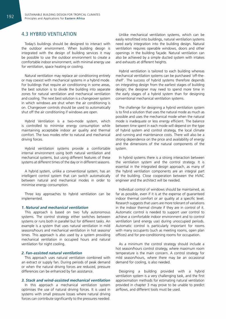
SUSTAINABLE BUILDING DESIGN FOR TROPICAL CLIMATES Principles and Applications for Eastern Africa192
4.3 hybrId venTIlaTIon
Today’s buildings should be designed to interact with the outdoor environment. When building design is integrated with the design of building services it may be possible to use the outdoor environment to create a comfortable indoor environment, with minimal energy use for ventilation, space heating or cooling.
Natural ventilation may replace air conditioning entirely or may coexist with mechanical systems in a hybrid mode. For buildings that require air conditioning in some areas, the best solution is to divide the building into separate zones for natural ventilation and mechanical ventilation and cooling. The next best solution is a changeover system in which windows are shut when the air conditioning is on. Changeover controls should be used to automatically shut off the air conditioning if windows are open.
Hybrid Ventilation is a two-mode system, which is controlled to minimise energy consumption while maintaining acceptable indoor air quality and thermal comfort. The two modes refer to natural and mechanical driving forces.
Hybrid ventilation systems provide a comfortable internal environment using both natural ventilation and mechanical systems, but using different features of these systems at different times of the day or in different seasons.
A hybrid system, unlike a conventional system, has an intelligent control system that can switch automatically between natural and mechanical modes in order to minimise energy consumption.
Three key approaches to hybrid ventilation can be implemented.
1. Natural and mechanical ventilationThis approach is based on two fully autonomous
systems. The control strategy either switches between systems or runs both in parallel but for different tasks. An example is a system that uses natural ventilation in mild seasons/hours and mechanical ventilation in hot seasons/times. This approach is also used by a system providing mechanical ventilation in occupied hours and natural ventilation for night cooling.
2. Fan-assisted natural ventilationThis approach uses natural ventilation combined with
an extract or supply fan. During periods of peak demand or when the natural driving forces are reduced, pressure differences can be enhanced by fan assistance.
3. Stack and wind-assisted mechanical ventilationIn this approach a mechanical ventilation system
optimises the use of natural driving forces. It is used in systems with small pressure losses where natural driving forces can contribute significantly to the pressures needed.
Unlike mechanical ventilation systems, which can be easily retrofitted into buildings, natural ventilation systems need early integration into the building design. Natural ventilation requires operable windows, doors and other openings in the building façade. Natural ventilation can also be achieved by a simple ducted system with intakes and exhausts at different heights.
Hybrid ventilation is tailored to each building whereas mechanical ventilation systems can be purchased ‘off-the-shelf’. The success of hybrid systems therefore depends on integrating design from the earliest stages of building design; the designer may need to spend more time in the early stages of a hybrid system than for designing conventional mechanical ventilation systems.
The challenge for designing a hybrid ventilation system is to find a solution that uses the natural mode as much as possible and uses the mechanical mode when the natural mode is inadequate or less energy efficient. The balance between time spent in each mode will depend on the type of hybrid system and control strategy, the local climate and running and maintenance costs. There will also be a strong dependence on the price and availability of energy and the dimensions of the natural components of the system.
In hybrid systems there is a strong interaction between the ventilation system and the control strategy. It is essential in the integrated design approach, as many of the hybrid ventilation components are an integral part of the building. Close cooperation between the HVAC engineer and the architect will be needed.
Individual control of windows should be maintained, as far as possible, even if it is at the expense of guaranteed indoor thermal comfort or air quality at a specific level. Research suggests that users are more tolerant of variations in the indoor thermal climate if they are in control of it. Automatic control is needed to support user control to achieve a comfortable indoor environment and to control ventilation (and energy use) during unoccupied periods. Automatic control is particularly important for rooms with many occupants (such as meeting rooms, open plan offices) and for pre-conditioning rooms for occupation.
As a minimum the control strategy should include a hot season/hours control strategy, where maximum room temperature is the main concern. A control strategy for mild season/hours, where there may be an occasional demand for cooling, is also needed.
Designing a building provided with a hybrid ventilation system is a very challenging task, and the first approximation methods for estimating natural ventilation provided in chapter 3 may prove to be unable to predict airflows, and different tools must be used.
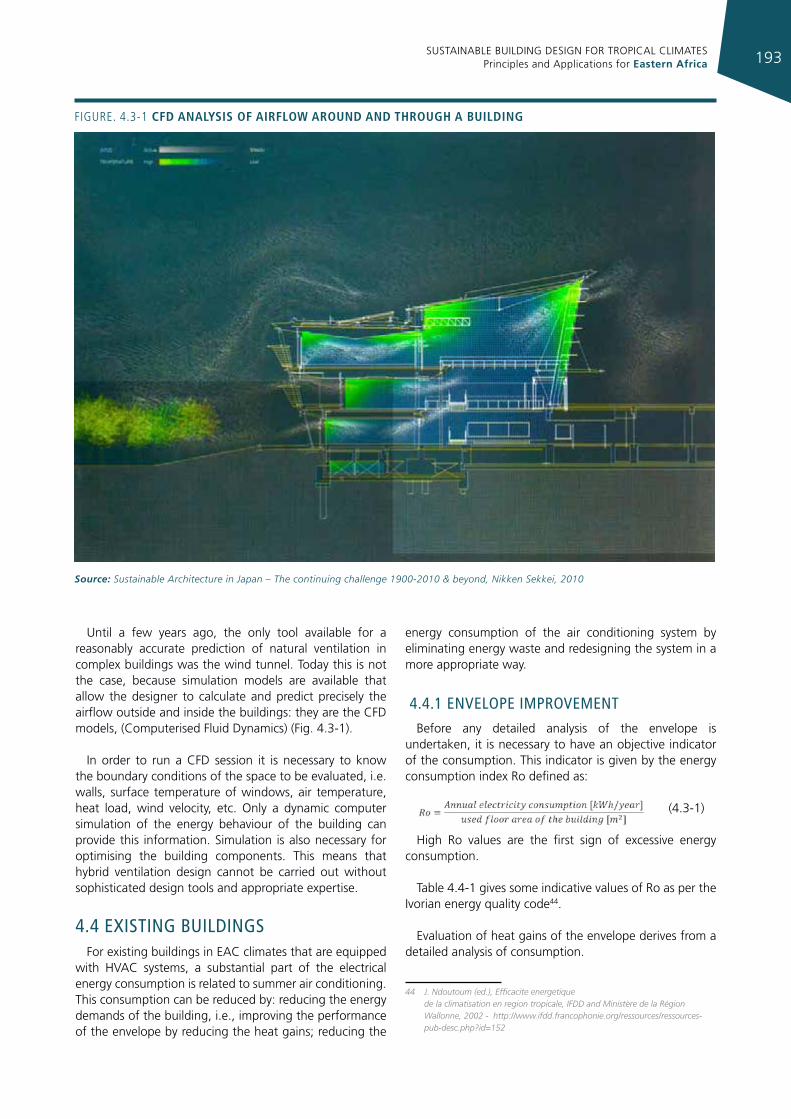
SUSTAINABLE BUILDING DESIGN FOR TROPICAL CLIMATES Principles and Applications for Eastern Africa 193
Until a few years ago, the only tool available for a reasonably accurate prediction of natural ventilation in complex buildings was the wind tunnel. Today this is not the case, because simulation models are available that allow the designer to calculate and predict precisely the airflow outside and inside the buildings: they are the CFD models, (Computerised Fluid Dynamics) (Fig. 4.3-1).
In order to run a CFD session it is necessary to know the boundary conditions of the space to be evaluated, i.e. walls, surface temperature of windows, air temperature, heat load, wind velocity, etc. Only a dynamic computer simulation of the energy behaviour of the building can provide this information. Simulation is also necessary for optimising the building components. This means that hybrid ventilation design cannot be carried out without sophisticated design tools and appropriate expertise.
4.4 exIsTIng buIldIngsFor existing buildings in EAC climates that are equipped
with HVAC systems, a substantial part of the electrical energy consumption is related to summer air conditioning. This consumption can be reduced by: reducing the energy demands of the building, i.e., improving the performance of the envelope by reducing the heat gains; reducing the
energy consumption of the air conditioning system by eliminating energy waste and redesigning the system in a more appropriate way.
4.4.1 envelope ImprovemenT
Before any detailed analysis of the envelope is undertaken, it is necessary to have an objective indicator of the consumption. This indicator is given by the energy consumption index Ro defined as:
(4.3-1)
High Ro values are the first sign of excessive energy consumption.
Table 4.4-1 gives some indicative values of Ro as per the Ivorian energy quality code44.
Evaluation of heat gains of the envelope derives from a detailed analysis of consumption.
44 J. Ndoutoum (ed.), Efficacite energetique de la climatisation en region tropicale, IFDD and Ministère de la Région Wallonne, 2002 - http://www.ifdd.francophonie.org/ressources/ressources-pub-desc.php?id=152
Figure. 4.3-1 cfd analysIs of aIrfloW around and through a buIldIng
Source: Sustainable Architecture in Japan – The continuing challenge 1900-2010 & beyond, Nikken Sekkei, 2010
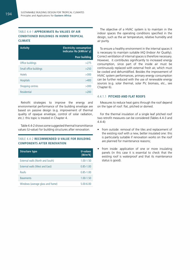
SUSTAINABLE BUILDING DESIGN FOR TROPICAL CLIMATES Principles and Applications for Eastern Africa194
Retrofit strategies to improve the energy and environmental performance of the building envelope are based on passive design (e.g. improvement of thermal quality of opaque envelope, control of solar radiation, etc.): this topic is treated in Chapter 4.
Table 4.4-2 shows some suggested thermal transmittance values (U-value) for building structures after renovation.
The objective of a HVAC system is to maintain in the indoor spaces the operating conditions specified in the design, such as the air temperature, relative humidity and air purity.
To ensure a healthy environment in the internal spaces it is necessary to maintain suitable IAQ (Indoor Air Quality). Correct ventilation of internal spaces is therefore necessary. However, it contributes significantly to increased energy consumption, since part of the inside air must be continuously replaced with external fresh air, which must be cooled and dehumidified. Besides the improvement of HVAC system performances, primary energy consumption can be further reduced with the use of renewable energy sources (e.g. solar thermal, solar PV, biomass, etc., see Chapter 6).
4.4.1.1 pItched and flat roofs
Measures to reduce heat gains through the roof depend on the type of roof: flat, pitched or domed.
For the thermal insulation of a single leaf pitched roof two retrofit measures can be considered (Tables 4.4-3 and 4.4-4):
• from outside: removal of the tiles and replacement of the existing roof with a new, better insulated one: this is particularly suitable if renovation works on the roof are planned for maintenance reasons;
• from inside: application of one or more insulating panels (in this case it is essential to check that the existing roof is waterproof and that its maintenance status is good).
TABLe 4.4-1 approxImate ro values of aIr condItIoned buIldIngs In humId tropIcal clImate
activity electricity consumption indicator ro [kWh/m2 y]
poor building
Office buildings >275
Small office buildings >250
Hotels >300
Hospitals >400
Shopping centres >300
residential >200
TABLe 4.4-2 recommended u-value for buIldIng components after renovatIon
structure type u-values [W/m2k]
external walls (North and South) 1.00-1.50
external walls (West and east) 0.85-1.00
roofs 0.85-1.00
Basements 1.00-1.50
Windows (average glass and frame) 5.00-6.00
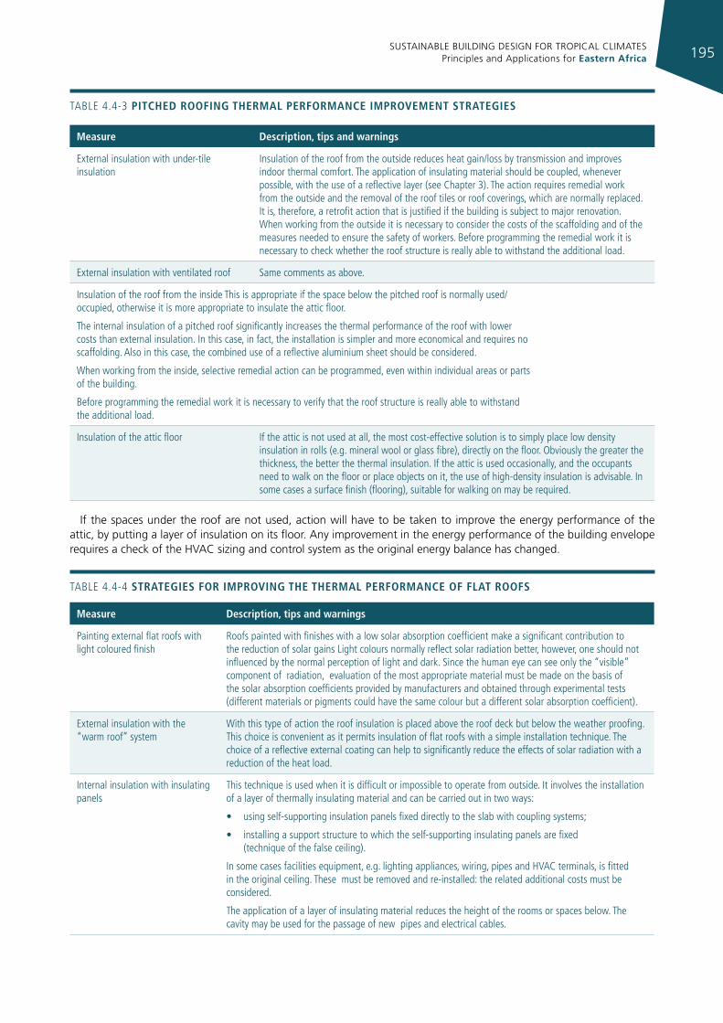
SUSTAINABLE BUILDING DESIGN FOR TROPICAL CLIMATES Principles and Applications for Eastern Africa 195
TABLe 4.4-3 pItched roofIng thermal performance Improvement strategIes
measure description, tips and warnings
external insulation with under-tile insulation
insulation of the roof from the outside reduces heat gain/loss by transmission and improves indoor thermal comfort. The application of insulating material should be coupled, whenever possible, with the use of a reflective layer (see Chapter 3). The action requires remedial work from the outside and the removal of the roof tiles or roof coverings, which are normally replaced. it is, therefore, a retrofit action that is justified if the building is subject to major renovation. When working from the outside it is necessary to consider the costs of the scaffolding and of the measures needed to ensure the safety of workers. Before programming the remedial work it is necessary to check whether the roof structure is really able to withstand the additional load.
external insulation with ventilated roof Same comments as above.
insulation of the roof from the inside This is appropriate if the space below the pitched roof is normally used/occupied, otherwise it is more appropriate to insulate the attic floor.
The internal insulation of a pitched roof significantly increases the thermal performance of the roof with lower costs than external insulation. in this case, in fact, the installation is simpler and more economical and requires no scaffolding. Also in this case, the combined use of a reflective aluminium sheet should be considered.
When working from the inside, selective remedial action can be programmed, even within individual areas or parts of the building.
Before programming the remedial work it is necessary to verify that the roof structure is really able to withstand the additional load.
insulation of the attic floor if the attic is not used at all, the most cost-effective solution is to simply place low density insulation in rolls (e.g. mineral wool or glass fibre), directly on the floor. Obviously the greater the thickness, the better the thermal insulation. if the attic is used occasionally, and the occupants need to walk on the floor or place objects on it, the use of high-density insulation is advisable. in some cases a surface finish (flooring), suitable for walking on may be required.
If the spaces under the roof are not used, action will have to be taken to improve the energy performance of the attic, by putting a layer of insulation on its floor. Any improvement in the energy performance of the building envelope requires a check of the HVAC sizing and control system as the original energy balance has changed.
TABLe 4.4-4 strategIes for ImprovIng the thermal performance of flat roofs
measure description, tips and warnings
Painting external flat roofs with light coloured finish
roofs painted with finishes with a low solar absorption coefficient make a significant contribution to the reduction of solar gains Light colours normally reflect solar radiation better, however, one should not influenced by the normal perception of light and dark. Since the human eye can see only the “visible” component of radiation, evaluation of the most appropriate material must be made on the basis of the solar absorption coefficients provided by manufacturers and obtained through experimental tests (different materials or pigments could have the same colour but a different solar absorption coefficient).
external insulation with the “warm roof” system
With this type of action the roof insulation is placed above the roof deck but below the weather proofing. This choice is convenient as it permits insulation of flat roofs with a simple installation technique. The choice of a reflective external coating can help to significantly reduce the effects of solar radiation with a reduction of the heat load.
internal insulation with insulating panels
This technique is used when it is difficult or impossible to operate from outside. it involves the installation of a layer of thermally insulating material and can be carried out in two ways:
• using self-supporting insulation panels fixed directly to the slab with coupling systems;
• installing a support structure to which the self-supporting insulating panels are fixed (technique of the false ceiling).
in some cases facilities equipment, e.g. lighting appliances, wiring, pipes and HVAC terminals, is fitted in the original ceiling. These must be removed and re-installed: the related additional costs must be considered.
The application of a layer of insulating material reduces the height of the rooms or spaces below. The cavity may be used for the passage of new pipes and electrical cables.
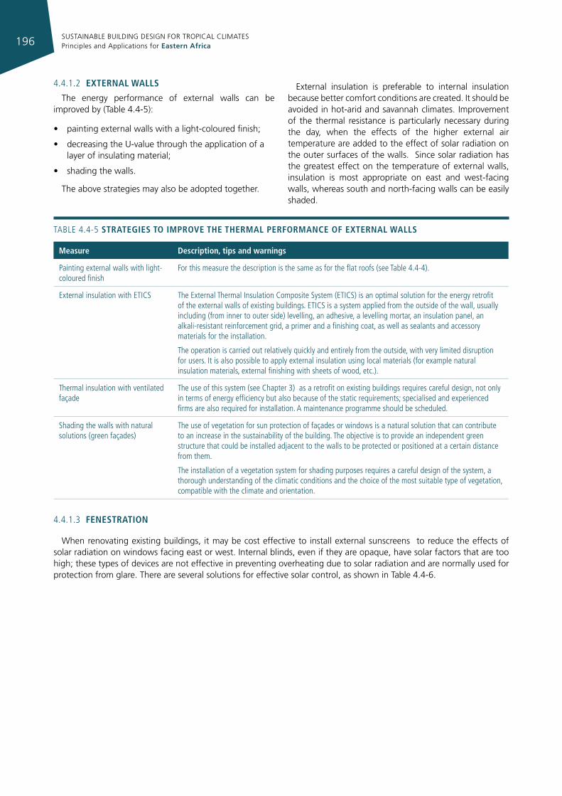
SUSTAINABLE BUILDING DESIGN FOR TROPICAL CLIMATES Principles and Applications for Eastern Africa196
4.4.1.2 external Walls
The energy performance of external walls can be improved by (Table 4.4-5):
• painting external walls with a light-coloured finish;
• decreasing the U-value through the application of a layer of insulating material;
• shading the walls.
The above strategies may also be adopted together.
External insulation is preferable to internal insulation because better comfort conditions are created. It should be avoided in hot-arid and savannah climates. Improvement of the thermal resistance is particularly necessary during the day, when the effects of the higher external air temperature are added to the effect of solar radiation on the outer surfaces of the walls. Since solar radiation has the greatest effect on the temperature of external walls, insulation is most appropriate on east and west-facing walls, whereas south and north-facing walls can be easily shaded.
TABLe 4.4-5 strategIes to Improve the thermal performance of external Walls
measure description, tips and warnings
Painting external walls with light-coloured finish
For this measure the description is the same as for the flat roofs (see Table 4.4-4).
external insulation with eTiCS The external Thermal insulation Composite System (eTiCS) is an optimal solution for the energy retrofit of the external walls of existing buildings. eTiCS is a system applied from the outside of the wall, usually including (from inner to outer side) levelling, an adhesive, a levelling mortar, an insulation panel, an alkali-resistant reinforcement grid, a primer and a finishing coat, as well as sealants and accessory materials for the installation.
The operation is carried out relatively quickly and entirely from the outside, with very limited disruption for users. it is also possible to apply external insulation using local materials (for example natural insulation materials, external finishing with sheets of wood, etc.).
Thermal insulation with ventilated façade
The use of this system (see Chapter 3) as a retrofit on existing buildings requires careful design, not only in terms of energy efficiency but also because of the static requirements; specialised and experienced firms are also required for installation. A maintenance programme should be scheduled.
Shading the walls with natural solutions (green façades)
The use of vegetation for sun protection of façades or windows is a natural solution that can contribute to an increase in the sustainability of the building. The objective is to provide an independent green structure that could be installed adjacent to the walls to be protected or positioned at a certain distance from them.
The installation of a vegetation system for shading purposes requires a careful design of the system, a thorough understanding of the climatic conditions and the choice of the most suitable type of vegetation, compatible with the climate and orientation.
4.4.1.3 fenestratIon
When renovating existing buildings, it may be cost effective to install external sunscreens to reduce the effects of solar radiation on windows facing east or west. Internal blinds, even if they are opaque, have solar factors that are too high; these types of devices are not effective in preventing overheating due to solar radiation and are normally used for protection from glare. There are several solutions for effective solar control, as shown in Table 4.4-6.
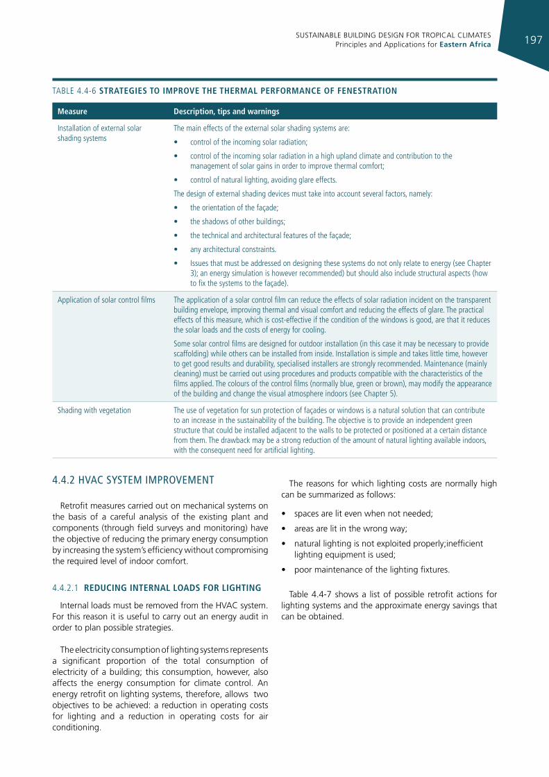
SUSTAINABLE BUILDING DESIGN FOR TROPICAL CLIMATES Principles and Applications for Eastern Africa 197
TABLe 4.4-6 strategIes to Improve the thermal performance of fenestratIon
measure description, tips and warnings
installation of external solar shading systems
The main effects of the external solar shading systems are:
• control of the incoming solar radiation;
• control of the incoming solar radiation in a high upland climate and contribution to the management of solar gains in order to improve thermal comfort;
• control of natural lighting, avoiding glare effects.
The design of external shading devices must take into account several factors, namely:
• the orientation of the façade;
• the shadows of other buildings;
• the technical and architectural features of the façade;
• any architectural constraints.
• issues that must be addressed on designing these systems do not only relate to energy (see Chapter 3); an energy simulation is however recommended) but should also include structural aspects (how to fix the systems to the façade).
Application of solar control films The application of a solar control film can reduce the effects of solar radiation incident on the transparent building envelope, improving thermal and visual comfort and reducing the effects of glare. The practical effects of this measure, which is cost-effective if the condition of the windows is good, are that it reduces the solar loads and the costs of energy for cooling.
Some solar control films are designed for outdoor installation (in this case it may be necessary to provide scaffolding) while others can be installed from inside. installation is simple and takes little time, however to get good results and durability, specialised installers are strongly recommended. Maintenance (mainly cleaning) must be carried out using procedures and products compatible with the characteristics of the films applied. The colours of the control films (normally blue, green or brown), may modify the appearance of the building and change the visual atmosphere indoors (see Chapter 5).
Shading with vegetation The use of vegetation for sun protection of façades or windows is a natural solution that can contribute to an increase in the sustainability of the building. The objective is to provide an independent green structure that could be installed adjacent to the walls to be protected or positioned at a certain distance from them. The drawback may be a strong reduction of the amount of natural lighting available indoors, with the consequent need for artificial lighting.
4.4.2 hvac sysTem ImprovemenT
Retrofit measures carried out on mechanical systems on the basis of a careful analysis of the existing plant and components (through field surveys and monitoring) have the objective of reducing the primary energy consumption by increasing the system’s efficiency without compromising the required level of indoor comfort.
4.4.2.1 reducIng Internal loads for lIghtIng
Internal loads must be removed from the HVAC system. For this reason it is useful to carry out an energy audit in order to plan possible strategies.
The electricity consumption of lighting systems represents a significant proportion of the total consumption of electricity of a building; this consumption, however, also affects the energy consumption for climate control. An energy retrofit on lighting systems, therefore, allows two objectives to be achieved: a reduction in operating costs for lighting and a reduction in operating costs for air conditioning.
The reasons for which lighting costs are normally high can be summarized as follows:
• spaces are lit even when not needed;
• areas are lit in the wrong way;
• natural lighting is not exploited properly;inefficient lighting equipment is used;
• poor maintenance of the lighting fixtures.
Table 4.4-7 shows a list of possible retrofit actions for lighting systems and the approximate energy savings that can be obtained.
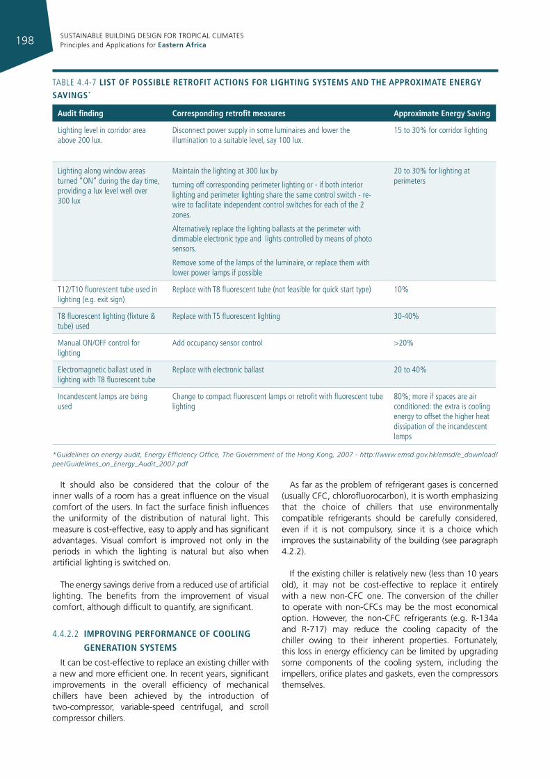
SUSTAINABLE BUILDING DESIGN FOR TROPICAL CLIMATES Principles and Applications for Eastern Africa198
TABLe 4.4-7 lIst of possIble retrofIt actIons for lIghtIng systems and the approxImate energy savIngs*
audit finding corresponding retrofit measures approximate energy saving
Lighting level in corridor area above 200 lux.
Disconnect power supply in some luminaires and lower the illumination to a suitable level, say 100 lux.
15 to 30% for corridor lighting
Lighting along window areas turned “ON” during the day time, providing a lux level well over 300 lux
Maintain the lighting at 300 lux by
turning off corresponding perimeter lighting or - if both interior lighting and perimeter lighting share the same control switch - re-wire to facilitate independent control switches for each of the 2 zones.
Alternatively replace the lighting ballasts at the perimeter with dimmable electronic type and lights controlled by means of photo sensors.
remove some of the lamps of the luminaire, or replace them with lower power lamps if possible
20 to 30% for lighting at perimeters
T12/T10 fluorescent tube used in lighting (e.g. exit sign)
replace with T8 fluorescent tube (not feasible for quick start type) 10%
T8 fluorescent lighting (fixture & tube) used
replace with T5 fluorescent lighting 30-40%
Manual ON/OFF control for lighting
Add occupancy sensor control >20%
electromagnetic ballast used in lighting with T8 fluorescent tube
replace with electronic ballast 20 to 40%
incandescent lamps are being used
Change to compact fluorescent lamps or retrofit with fluorescent tube lighting
80%; more if spaces are air conditioned: the extra is cooling energy to offset the higher heat dissipation of the incandescent lamps
*Guidelines on energy audit, Energy Efficiency Office, The Government of the Hong Kong, 2007 - http://www.emsd.gov.hk/emsd/e_download/pee/Guidelines_on_Energy_Audit_2007.pdf
It should also be considered that the colour of the inner walls of a room has a great influence on the visual comfort of the users. In fact the surface finish influences the uniformity of the distribution of natural light. This measure is cost-effective, easy to apply and has significant advantages. Visual comfort is improved not only in the periods in which the lighting is natural but also when artificial lighting is switched on.
The energy savings derive from a reduced use of artificial lighting. The benefits from the improvement of visual comfort, although difficult to quantify, are significant.
4.4.2.2 ImprovIng performance of coolIng
generatIon systems
It can be cost-effective to replace an existing chiller with a new and more efficient one. In recent years, significant improvements in the overall efficiency of mechanical chillers have been achieved by the introduction of two-compressor, variable-speed centrifugal, and scroll compressor chillers.
As far as the problem of refrigerant gases is concerned (usually CFC, chlorofluorocarbon), it is worth emphasizing that the choice of chillers that use environmentally compatible refrigerants should be carefully considered, even if it is not compulsory, since it is a choice which improves the sustainability of the building (see paragraph 4.2.2).
If the existing chiller is relatively new (less than 10 years old), it may not be cost-effective to replace it entirely with a new non-CFC one. The conversion of the chiller to operate with non-CFCs may be the most economical option. However, the non-CFC refrigerants (e.g. R-134a and R-717) may reduce the cooling capacity of the chiller owing to their inherent properties. Fortunately, this loss in energy efficiency can be limited by upgrading some components of the cooling system, including the impellers, orifice plates and gaskets, even the compressors themselves.
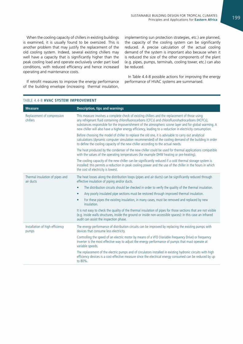
SUSTAINABLE BUILDING DESIGN FOR TROPICAL CLIMATES Principles and Applications for Eastern Africa 199
When the cooling capacity of chillers in existing buildings is examined, it is usually found to be oversized. This is another problem that may justify the replacement of the old cooling system. Indeed, several existing chillers may well have a capacity that is significantly higher than the peak cooling load and operate exclusively under part load conditions, with reduced efficiency and hence increased operating and maintenance costs.
If retrofit measures to improve the energy performance of the building envelope (increasing thermal insulation,
implementing sun protection strategies, etc.) are planned, the capacity of the cooling system can be significantly reduced. A precise calculation of the actual cooling demand of the system is important also because when it is reduced the size of the other components of the plant (e.g. pipes, pumps, terminals, cooling tower, etc.) can also be reduced.
In Table 4.4-8 possible actions for improving the energy performance of HVAC systems are summarised.
TABLe 4.4-8 hvac system Improvement
measure description, tips and warnings
replacement of compression chillers
This measure involves a complete check of existing chillers and the replacement of those using any refrigerant fluid containing chlorofluorocarbons (CFCs) and chlorofluorohydrocarbons (HCFCs), substances responsible for the impoverishment of the atmospheric ozone layer and for global warming. A new chiller will also have a higher energy efficiency, leading to a reduction in electricity consumption.
Before choosing the model of chiller to replace the old one, it is advisable to carry out analytical calculations (dynamic computer simulation recommended) of the cooling demand of the building in order to define the cooling capacity of the new chiller according to the actual needs.
The heat produced by the condenser of the new chiller could be used for thermal applications compatible with the values of the operating temperatures (for example DHW heating or pre-heating).
The cooling capacity of the new chiller can be significantly reduced if a cold thermal storage system is installed: this permits a reduction in peak cooling power and the use of the chiller in the hours in which the cost of electricity is lowest.
Thermal insulation of pipes and air ducts
The heat losses along the distribution loops (pipes and air ducts) can be significantly reduced through effective insulation of piping and/or ducts.
• The distribution circuits should be checked in order to verify the quality of the thermal insulation.
• Any poorly insulated pipe sections must be restored through improved thermal insulation.
• For these pipes the existing insulation, in many cases, must be removed and replaced by new insulation.
it is not easy to check the quality of the thermal insulation of pipes for those sections that are not visible (e.g. inside walls structures, inside the ground or inside non-accessible spaces): in this case an infrared audit can assist the inspection phase.
installation of high efficiency pumps
The energy performance of distribution circuits can be improved by replacing the existing pumps with devices that consume less electricity.
Controlling the speed of an electric motor by means of a VFD (Variable Frequency Drive) or frequency inverter is the most effective way to adjust the energy performance of pumps that must operate at variable speeds.
The replacement of the electric pumps and of circulators installed in existing hydronic circuits with high efficiency devices is a cost-effective measure since the electrical energy consumed can be reduced by up to 80%.
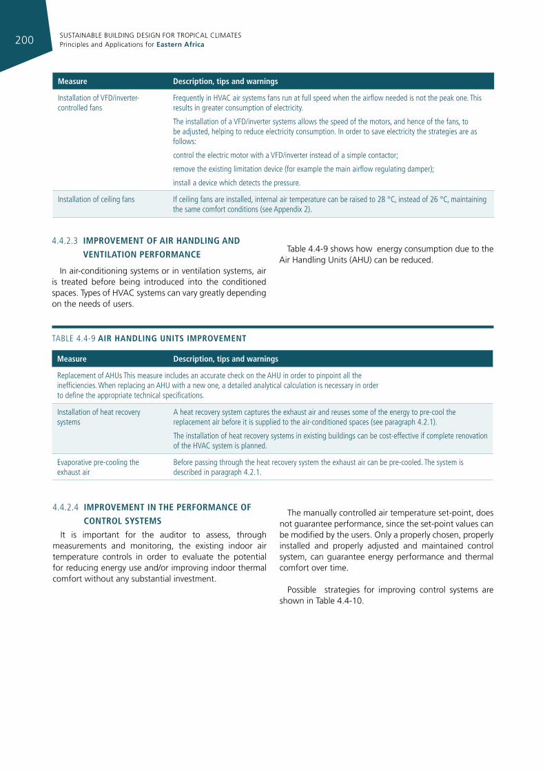
SUSTAINABLE BUILDING DESIGN FOR TROPICAL CLIMATES Principles and Applications for Eastern Africa200
measure description, tips and warnings
installation of VFD/inverter-controlled fans
Frequently in HVAC air systems fans run at full speed when the airflow needed is not the peak one. This results in greater consumption of electricity.
The installation of a VFD/inverter systems allows the speed of the motors, and hence of the fans, to be adjusted, helping to reduce electricity consumption. in order to save electricity the strategies are as follows:
control the electric motor with a VFD/inverter instead of a simple contactor;
remove the existing limitation device (for example the main airflow regulating damper);
install a device which detects the pressure.
installation of ceiling fans if ceiling fans are installed, internal air temperature can be raised to 28 °C, instead of 26 °C, maintaining the same comfort conditions (see Appendix 2).
4.4.2.3 Improvement of aIr handlIng and
ventIlatIon performance
In air-conditioning systems or in ventilation systems, air is treated before being introduced into the conditioned spaces. Types of HVAC systems can vary greatly depending on the needs of users.
Table 4.4-9 shows how energy consumption due to the Air Handling Units (AHU) can be reduced.
TABLe 4.4-9 aIr handlIng unIts Improvement
measure description, tips and warnings
replacement of AHus This measure includes an accurate check on the AHu in order to pinpoint all the inefficiencies. When replacing an AHu with a new one, a detailed analytical calculation is necessary in order to define the appropriate technical specifications.
installation of heat recovery systems
A heat recovery system captures the exhaust air and reuses some of the energy to pre-cool the replacement air before it is supplied to the air-conditioned spaces (see paragraph 4.2.1).
The installation of heat recovery systems in existing buildings can be cost-effective if complete renovation of the HVAC system is planned.
evaporative pre-cooling the exhaust air
Before passing through the heat recovery system the exhaust air can be pre-cooled. The system is described in paragraph 4.2.1.
4.4.2.4 Improvement In the performance of
control systemsIt is important for the auditor to assess, through
measurements and monitoring, the existing indoor air temperature controls in order to evaluate the potential for reducing energy use and/or improving indoor thermal comfort without any substantial investment.
The manually controlled air temperature set-point, does not guarantee performance, since the set-point values can be modified by the users. Only a properly chosen, properly installed and properly adjusted and maintained control system, can guarantee energy performance and thermal comfort over time.
Possible strategies for improving control systems are shown in Table 4.4-10.
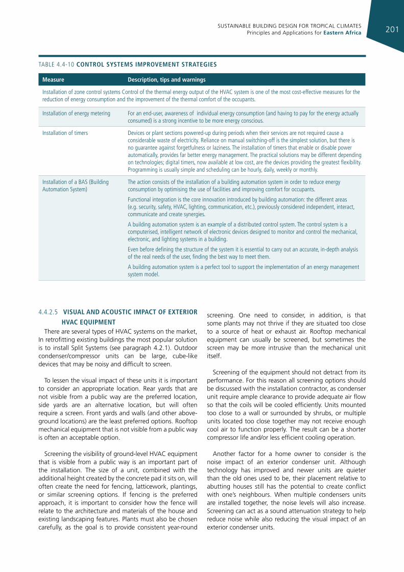
SUSTAINABLE BUILDING DESIGN FOR TROPICAL CLIMATES Principles and Applications for Eastern Africa 201
TABLe 4.4-10 control systems Improvement strategIes
measure description, tips and warnings
installation of zone control systems Control of the thermal energy output of the HVAC system is one of the most cost-effective measures for the reduction of energy consumption and the improvement of the thermal comfort of the occupants.
installation of energy metering For an end-user, awareness of individual energy consumption (and having to pay for the energy actually consumed) is a strong incentive to be more energy conscious.
installation of timers Devices or plant sections powered-up during periods when their services are not required cause a considerable waste of electricity. reliance on manual switching-off is the simplest solution, but there is no guarantee against forgetfulness or laziness. The installation of timers that enable or disable power automatically, provides far better energy management. The practical solutions may be different depending on technologies; digital timers, now available at low cost, are the devices providing the greatest flexibility. Programming is usually simple and scheduling can be hourly, daily, weekly or monthly.
installation of a BAS (Building Automation System)
The action consists of the installation of a building automation system in order to reduce energy consumption by optimising the use of facilities and improving comfort for occupants.
Functional integration is the core innovation introduced by building automation: the different areas (e.g. security, safety, HVAC, lighting, communication, etc.), previously considered independent, interact, communicate and create synergies.
A building automation system is an example of a distributed control system. The control system is a computerised, intelligent network of electronic devices designed to monitor and control the mechanical, electronic, and lighting systems in a building.
even before defining the structure of the system it is essential to carry out an accurate, in-depth analysis of the real needs of the user, finding the best way to meet them.
A building automation system is a perfect tool to support the implementation of an energy management system model.
4.4.2.5 vIsual and acoustIc Impact of exterIor
hvac equIpmentThere are several types of HVAC systems on the market,
In retrofitting existing buildings the most popular solution is to install Split Systems (see paragraph 4.2.1). Outdoor condenser/compressor units can be large, cube-like devices that may be noisy and difficult to screen.
To lessen the visual impact of these units it is important to consider an appropriate location. Rear yards that are not visible from a public way are the preferred location, side yards are an alternative location, but will often require a screen. Front yards and walls (and other above-ground locations) are the least preferred options. Rooftop mechanical equipment that is not visible from a public way is often an acceptable option.
Screening the visibility of ground-level HVAC equipment that is visible from a public way is an important part of the installation. The size of a unit, combined with the additional height created by the concrete pad it sits on, will often create the need for fencing, latticework, plantings, or similar screening options. If fencing is the preferred approach, it is important to consider how the fence will relate to the architecture and materials of the house and existing landscaping features. Plants must also be chosen carefully, as the goal is to provide consistent year-round
screening. One need to consider, in addition, is that some plants may not thrive if they are situated too close to a source of heat or exhaust air. Rooftop mechanical equipment can usually be screened, but sometimes the screen may be more intrusive than the mechanical unit itself.
Screening of the equipment should not detract from its performance. For this reason all screening options should be discussed with the installation contractor, as condenser unit require ample clearance to provide adequate air flow so that the coils will be cooled efficiently. Units mounted too close to a wall or surrounded by shrubs, or multiple units located too close together may not receive enough cool air to function properly. The result can be a shorter compressor life and/or less efficient cooling operation.
Another factor for a home owner to consider is the noise impact of an exterior condenser unit. Although technology has improved and newer units are quieter than the old ones used to be, their placement relative to abutting houses still has the potential to create conflict with one’s neighbours. When multiple condensers units are installed together, the noise levels will also increase. Screening can act as a sound attenuation strategy to help reduce noise while also reducing the visual impact of an exterior condenser units.
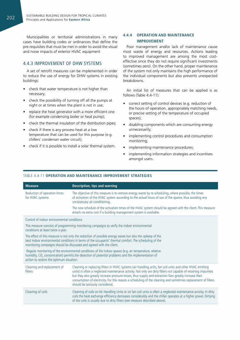
SUSTAINABLE BUILDING DESIGN FOR TROPICAL CLIMATES Principles and Applications for Eastern Africa202
Municipalities or territorial administrations in many cases have building codes or ordinances that define the pre-requisites that must be met in order to avoid the visual and noise impacts of exterior HVAC equipment
4.4.3 ImprovemenT of dhw sysTems
A set of retrofit measures can be implemented in order to reduce the use of energy for DHW systems in existing buildings:
• check that water temperature is not higher than necessary;
• check the possibility of turning off all the pumps at night or at times when the plant is not in use;
• replace the heat generator with a more efficient one (for example condensing boiler or heat pump);
• check the thermal insulation of the distribution pipes;
• check if there is any process heat at a low temperature that can be used for this purpose (e.g. chillers’ condenser water circuit);
• check if it is possible to install a solar thermal system.
4.4.4 operatIon and maIntenance
ImprovementPoor management and/or lack of maintenance cause
most waste of energy and resources. Actions leading to improved management are among the most cost-effective since they do not require significant investments (sometimes zero). On the other hand, proper maintenance of the system not only maintains the high performance of the individual components but also prevents unexpected breakdowns.
An initial list of measures that can be applied is as follows (Table 4.4-11):
• correct setting of control devices (e.g. reduction of the hours of operation, appropriately matching needs, or precise setting of the temperature of occupied spaces);
• disabling components which are consuming energy unnecessarily;
• implementing control procedures and consumption monitoring;
• implementing maintenance procedures;
• implementing information strategies and incentives amongst users.
TABLe 4.4-11 operatIon and maIntenance Improvement strategIes
measure description, tips and warning
reduction of operation times for HVAC systems
The objective of this measure is to remove energy waste by re-scheduling, where possible, the times of activation of the HVAC system according to the actual hours of use of the spaces, thus avoiding any unnecessary air-conditioning.
The new schedule of the activation times of the HVAC system should be agreed with the client. This measure entails no extra cost if a building management system is available.
Control of indoor environmental conditions
This measure consists of programming monitoring campaigns to verify the indoor environmental conditions at least twice a year.
The effect of this measure is not only the reduction of possible energy waste but also the upkeep of the best indoor environmental conditions in terms of the occupants’ thermal comfort. The scheduling of the monitoring campaigns should be discussed and agreed with the client.
regular monitoring of the environmental conditions of the indoor spaces (e.g. air temperature, relative humidity, CO2 concentration) permits the detection of potential problems and the implementation of action to restore the optimum situation.
Cleaning and replacement of filters
Cleaning or replacing filters in HVAC systems (air handling units, fan coil units and other HVAC emitting units) is often a neglected maintenance activity. Not only are dirty filters not capable of retaining impurities but they also greatly increase pressure losses, thus supply and extraction fans greatly increase their consumption of electricity. For this reason a scheduling of the cleaning and sometimes replacement of filters should be seriously considered.
Cleaning of coils Cleaning of coils on Air Handling units or on fan-coil units is often a neglected maintenance activity. in dirty coils the heat exchange efficiency decreases considerably and the chiller operates at a higher power. Dirtying of the coils is usually due to dirty filters (see measure described above).
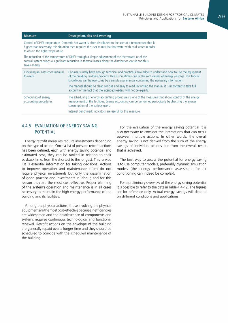
SUSTAINABLE BUILDING DESIGN FOR TROPICAL CLIMATES Principles and Applications for Eastern Africa 203
measure description, tips and warning
Control of DHW temperature Domestic hot water is often distributed to the user at a temperature that is higher than necessary: this situation then requires the user to mix that hot water with cold water in order to obtain the right temperature.
The reduction of the temperature of DHW through a simple adjustment of the thermostat or of the control system brings a significant reduction in thermal losses along the distribution circuit and thus saves energy.
Providing an instruction manual to users
end-users rarely have enough technical and practical knowledge to understand how to use the equipment of the building facilities properly. This is sometimes one of the root causes of energy wastage. This lack of knowledge can be overcome by a simple user manual containing the necessary information.
The manual should be clear, concise and easy to read. in writing the manual it is important to take full account of the fact that the intended readers will not be experts.
Scheduling of energy accounting procedures
The scheduling of energy accounting procedures is one of the measures that allows control of the energy management of the facilities. energy accounting can be performed periodically by checking the energy consumption of the various users.
internal benchmark indicators are useful for this measure.
4.4.5 evaluaTIon of energy savIng poTenTIal
Energy retrofit measures require investments depending on the type of action. Once a list of possible retrofit actions has been defined, each with energy saving potential and estimated cost, they can be ranked in relation to their payback time, from the shortest to the longest. This ranked list is essential information for taking decisions. Actions to improve operation and maintenance often do not require physical investments but only the dissemination of good practice and investments in labour, and for this reason they are the most cost-effective. Proper planning of the system’s operation and maintenance is in all cases necessary to maintain the high energy performance of the building and its facilities.
Among the physical actions, those involving the physical equipment are the most cost-effective because inefficiencies are widespread and the obsolescence of components and systems requires continuous technological and functional renewal. Retrofit actions on the envelope of the building are generally repaid over a longer time and they should be scheduled to coincide with the scheduled maintenance of the building.
For the evaluation of the energy saving potential it is also necessary to consider the interactions that can occur between multiple actions. In other words, the overall energy saving is not derived from the sum of the energy savings of individual actions but from the overall result that is achieved.
The best way to assess the potential for energy saving is to use computer models, preferably dynamic simulation models (the energy performance assessment for air conditioning can indeed be complex).
For a preliminary overview of the energy saving potential it is possible to refer to the data in Table 4.4-12. The figures are for reference only. Actual energy savings will depend on different conditions and applications.
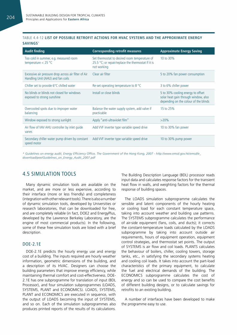
SUSTAINABLE BUILDING DESIGN FOR TROPICAL CLIMATES Principles and Applications for Eastern Africa204
TABLe 4.4-12 lIst of possIble retrofIt actIons for hvac systems and the approxImate energy savIngs*
audit finding corresponding retrofit measures approximate energy saving
Too cold in summer, e.g. measured room temperature < 25 °C
Set thermostat to desired room temperature of 25.5 °C; or repair/replace the thermostat if it is not working
10 to 30%
excessive air pressure drop across air filter of Air Handling unit (AHu) and fan coils
Clear air filter 5 to 20% fan power consumption
Chiller set to provide 6°C chilled water re-set operating temperature to 8 °C 3 to 6% chiller power
No blinds or blinds not closed for windows exposed to strong sunshine
install or close blinds 5 to 30% cooling energy to offset solar heat gain through window, also depending on the colour of the blinds
Overcooled spots due to improper water balancing
Balance the water supply system, add valve if practicable
15 to 25%
Window exposed to strong sunlight Apply “anti-ultraviolet film” >20%
Air flow of VAV AHu controller by inlet guide vanes
Add VVF inverter type variable speed drive 10 to 30% fan power
Secondary chiller water pump driven by constant speed motor
Add VVF inverter type variable speed drive 10 to 30% pump power
* Guidelines on energy audit, Energy Efficiency Office, The Government of the Hong Kong, 2007 - http://www.emsd.gov.hk/emsd/e_download/pee/Guidelines_on_Energy_Audit_2007.pdf
4.5 sImulaTIon Tools
Many dynamic simulation tools are available on the market, and are more or less expensive, according to their interface (more or less friendly) and completeness (integration with other relevant tools). There is also a number of dynamic simulation tools, developed by Universities or research laboratories, that can be downloaded for free, and are completely reliable (in fact, DOE2 and EnergyPlus, developed by the Lawrence Berkeley Laboratory, are the engine of most commercial products). In the following, some of these free simulation tools are listed with a brief description.
doe-2.1e
DOE-2.1E predicts the hourly energy use and energy cost of a building. The inputs required are hourly weather information, geometric dimensions of the building, and a description of its HVAC. Designers can choose the building parameters that improve energy efficiency, while maintaining thermal comfort and cost-effectiveness. DOE-2.1E has one subprogramme for translation of input (BDL Processor), and four simulation subprogrammes (LOADS, SYSTEMS, PLANT and ECONOMICS). LOADS, SYSTEMS, PLANT and ECONOMICS are executed in sequence, with the output of LOADS becoming the input of SYSTEMS, and so on. Each of the simulation subprogrammes also produces printed reports of the results of its calculations.
The Building Description Language (BDL) processor reads input data and calculates response factors for the transient heat flow in walls, and weighting factors for the thermal response of building spaces.
The LOADS simulation subprogramme calculates the sensible and latent components of the hourly heating or cooling load for each constant temperature space, taking into account weather and building use patterns. The SYSTEMS subprogramme calculates the performance of air-side equipment (fans, coils, and ducts); it corrects the constant-temperature loads calculated by the LOADS subprogramme by taking into account outside air requirements, hours of equipment operation, equipment control strategies, and thermostat set points. The output of SYSTEMS is air flow and coil loads. PLANTS calculates the behaviour of boilers, chiller, cooling towers, storage tanks, etc., in satisfying the secondary systems heating and cooling coil loads. It takes into account the part-load characteristics of the primary equipment, to calculate the fuel and electrical demands of the building. The ECONOMICS subprogramme calculates the cost of energy and so can be used to compare the cost benefits of different building designs, or to calculate savings for retrofits to an existing building.
A number of interfaces have been developed to make the programme easy to use.
SUSTAINABLE BUILDING DESIGN FOR TROPICAL CLIMATES Principles and Applications for Eastern Africa 205
eQuesT
eQUEST is an easy to use building energy use analysis tool that provides professional-level results with an affordable level of effort. This is accomplished by combining a building creation wizard, an energy efficiency measure (EEM) wizard and a graphical results display module, with an enhanced DOE-2.2-derived building energy use simulation programme.
eQUEST features a building creation wizard that guides the user through the process of creating an effective building energy model. This involves following a series of steps that help one to describe the features of the design that would impact energy use such as architectural design, HVAC equipment, building type and size, floor plan layout, construction material, area usage and occupancy, and lighting system. After compiling a building description, eQUEST produces a detailed simulation of the building, as well as an estimate of how much energy the building would use.
Within eQUEST, DOE-2.2 performs an hourly simulation of the building design for a one-year period. It calculates heating or cooling loads for each hour of the year, based on factors such as walls, windows, glass, people, plug loads, and ventilation. DOE-2.2 also simulates the performance of fans, pumps, chillers, boilers, and other energy-consuming devices. During the simulation, DOE-2.2 tabulates the building’s projected use for various end uses.
eQUEST offers several graphical formats for viewing simulation results. It allows one to perform multiple simulations and view alternative results in side-by-side graphics. It offers features like: energy cost estimating, daylighting and lighting system control , and automatic implementation of common energy efficiency measures (by selecting preferred measures from a list).
energyplus
EnergyPlus is a modular, structured software tool based on the most popular features and capabilities of BLAST and DOE-2.1E. It is primarily a simulation engine; input and output are simple text files. EnergyPlus grew out of a perceived need to provide an integrated (simultaneous load and systems) simulation for accurate temperature and comfort prediction. Loads calculated (by a heat balance engine) at user-specified time step (15-minute default) are passed to the building system simulation module at the same time step. The EnergyPlus building systems simulation module, with a variable time step (down to 1 minute as needed), calculates the heating and cooling system, and plant and electrical system response. This integrated solution provides a more accurate space-temperature prediction, crucial for system and plant sizing, and occupant comfort and health calculations. Integrated simulation also allows users to evaluate realistic
system controls, moisture adsorption and desorption in building elements, radiant heating and cooling systems, and interzone air flow.
EnergyPlus has two basic components: a heat and mass balance simulation module, and a building systems simulation module. The heat balance module manages the surface and air heat balance, and acts as an interface between the heat balance and the building system simulation manager. EnergyPlus inherits three popular windows and daylighting models from DOE-2.1E − fenestration performance based on WINDOW 5 calculations, daylighting using the split-flux inter-reflection module, and antistrophic sky models. In addition, a new daylighting analysis module named ‘Delight’ has been integrated with EnergyPlus.
opensTudIo
Since EnergyPlus is the only simulation engine that requires a text input data file, some GUI to aid users in compiling this text file is necessary. OpenStudio is the first free plug-in for SketchUp45 that allows users to build the model geometry and to specify corresponding envelope components by using intuitive SketchUp drawing tools and interfaces. Furthermore, it allows the main characteristics of thermal zones like occupancy, ventilation rates, internal heat gains and set-point temperatures to be set.
BESTenergy is also a SketchUp based tool and was developed starting from the 1.08.395 version of OpenStudio plugin, with respect to which some specific modules were implemented, in order to make the modeling of some specific EnergyPlus objects more affordable and to better manage and design some architectural components. It also supports decisions on strategic aspects of architectural design that can highly improve building energy performance, even in the preliminary phases. For instance, it implements specific interface modules for definition of schedules, evaluations of occupant comfort , opaque and transparent constructions (with the capability to edit and import material libraries), solar shading devices and airflows due to natural ventilation.
Both of them are building envelope focused, so they currently provide only an ideal load conditioning system.
sImergy
Simergy is a very suitable software to model plant systems using EnergyPlus objects, by an interface that allows the user to drag and drop blocks and components in a graphical scheme in which characteristics of the single item can be edited, but its capabilities for modeling geometric ad zone properties are quite limited and cumbersome.
45 SketchUp is a free 3D modeling program.
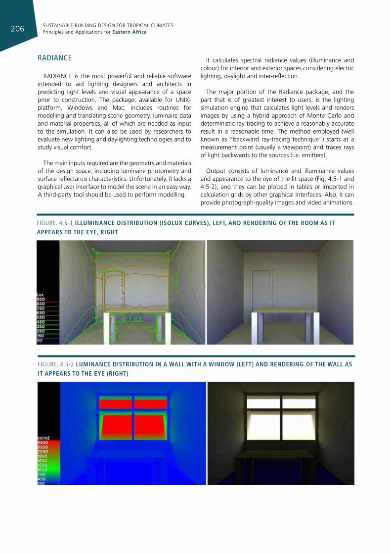
SUSTAINABLE BUILDING DESIGN FOR TROPICAL CLIMATES Principles and Applications for Eastern Africa206
radIance
RADIANCE is the most powerful and reliable software intended to aid lighting designers and architects in predicting light levels and visual appearance of a space prior to construction. The package, available for UNIX-platform, Windows and Mac, includes routines for modelling and translating scene geometry, luminaire data and material properties, all of which are needed as input to the simulation. It can also be used by researchers to evaluate new lighting and daylighting technologies and to study visual comfort.
The main inputs required are the geometry and materials of the design space, including luminaire photometry and surface reflectance characteristics. Unfortunately, it lacks a graphical user interface to model the scene in an easy way. A third-party tool should be used to perform modelling.
It calculates spectral radiance values (illuminance and colour) for interior and exterior spaces considering electric lighting, daylight and inter-reflection.
The major portion of the Radiance package, and the part that is of greatest interest to users, is the lighting simulation engine that calculates light levels and renders images by using a hybrid approach of Monte Carlo and deterministic ray tracing to achieve a reasonably accurate result in a reasonable time. The method employed (well known as “backward ray-tracing technique”) starts at a measurement point (usually a viewpoint) and traces rays of light backwards to the sources (i.e. emitters).
Output consists of luminance and illuminance values and appearance to the eye of the lit space (Fig. 4.5-1 and 4.5-2), and they can be plotted in tables or imported in calculation grids by other graphical interfaces. Also, it can provide photograph-quality images and video animations.
Figure. 4.5-1 IllumInance dIstrIbutIon (Isolux curves), left, and renderIng of the room as It appears to the eye, rIght
Figure. 4.5-2 lumInance dIstrIbutIon In a Wall WIth a WIndoW (left) and renderIng of the Wall as It appears to the eye (rIght)
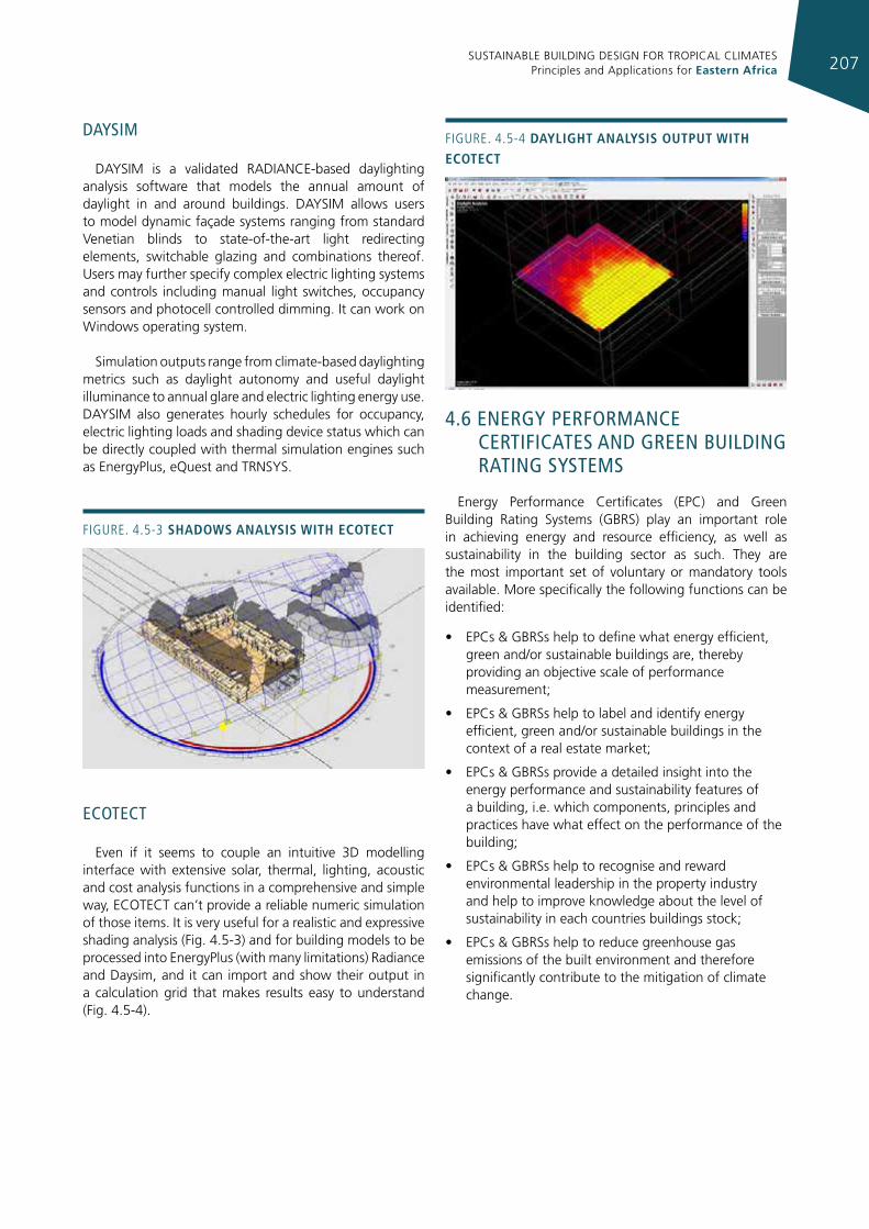
SUSTAINABLE BUILDING DESIGN FOR TROPICAL CLIMATES Principles and Applications for Eastern Africa 207
daysIm
DAYSIM is a validated RADIANCE-based daylighting analysis software that models the annual amount of daylight in and around buildings. DAYSIM allows users to model dynamic façade systems ranging from standard Venetian blinds to state-of-the-art light redirecting elements, switchable glazing and combinations thereof. Users may further specify complex electric lighting systems and controls including manual light switches, occupancy sensors and photocell controlled dimming. It can work on Windows operating system.
Simulation outputs range from climate-based daylighting metrics such as daylight autonomy and useful daylight illuminance to annual glare and electric lighting energy use. DAYSIM also generates hourly schedules for occupancy, electric lighting loads and shading device status which can be directly coupled with thermal simulation engines such as EnergyPlus, eQuest and TRNSYS.
ecoTecT
Even if it seems to couple an intuitive 3D modelling interface with extensive solar, thermal, lighting, acoustic and cost analysis functions in a comprehensive and simple way, ECOTECT can’t provide a reliable numeric simulation of those items. It is very useful for a realistic and expressive shading analysis (Fig. 4.5-3) and for building models to be processed into EnergyPlus (with many limitations) Radiance and Daysim, and it can import and show their output in a calculation grid that makes results easy to understand (Fig. 4.5-4).
4.6 energy performance cerTIfIcaTes and green buIldIng raTIng sysTems
Energy Performance Certificates (EPC) and Green Building Rating Systems (GBRS) play an important role in achieving energy and resource efficiency, as well as sustainability in the building sector as such. They are the most important set of voluntary or mandatory tools available. More specifically the following functions can be identified:
• EPCs & GBRSs help to define what energy efficient, green and/or sustainable buildings are, thereby providing an objective scale of performance measurement;
• EPCs & GBRSs help to label and identify energy efficient, green and/or sustainable buildings in the context of a real estate market;
• EPCs & GBRSs provide a detailed insight into the energy performance and sustainability features of a building, i.e. which components, principles and practices have what effect on the performance of the building;
• EPCs & GBRSs help to recognise and reward environmental leadership in the property industry and help to improve knowledge about the level of sustainability in each countries buildings stock;
• EPCs & GBRSs help to reduce greenhouse gas emissions of the built environment and therefore significantly contribute to the mitigation of climate change.
Figure. 4.5-3 shadoWs analysIs WIth ecotect
Figure. 4.5-4 daylIght analysIs output WIth ecotect
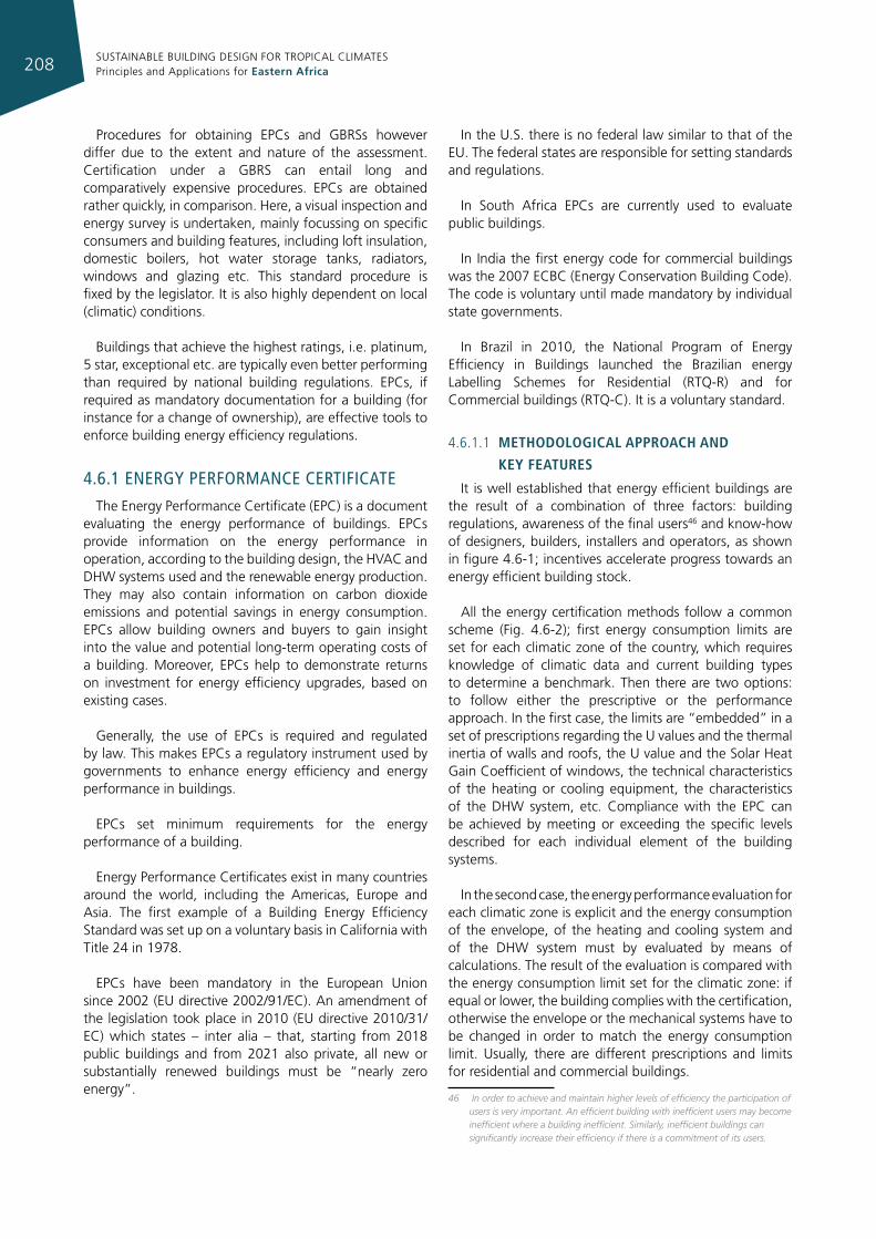
SUSTAINABLE BUILDING DESIGN FOR TROPICAL CLIMATES Principles and Applications for Eastern Africa208
Procedures for obtaining EPCs and GBRSs however differ due to the extent and nature of the assessment. Certification under a GBRS can entail long and comparatively expensive procedures. EPCs are obtained rather quickly, in comparison. Here, a visual inspection and energy survey is undertaken, mainly focussing on specific consumers and building features, including loft insulation, domestic boilers, hot water storage tanks, radiators, windows and glazing etc. This standard procedure is fixed by the legislator. It is also highly dependent on local (climatic) conditions.
Buildings that achieve the highest ratings, i.e. platinum, 5 star, exceptional etc. are typically even better performing than required by national building regulations. EPCs, if required as mandatory documentation for a building (for instance for a change of ownership), are effective tools to enforce building energy efficiency regulations.
4.6.1 energy performance cerTIfIcaTe
The Energy Performance Certificate (EPC) is a document evaluating the energy performance of buildings. EPCs provide information on the energy performance in operation, according to the building design, the HVAC and DHW systems used and the renewable energy production. They may also contain information on carbon dioxide emissions and potential savings in energy consumption. EPCs allow building owners and buyers to gain insight into the value and potential long-term operating costs of a building. Moreover, EPCs help to demonstrate returns on investment for energy efficiency upgrades, based on existing cases.
Generally, the use of EPCs is required and regulated by law. This makes EPCs a regulatory instrument used by governments to enhance energy efficiency and energy performance in buildings.
EPCs set minimum requirements for the energy performance of a building.
Energy Performance Certificates exist in many countries around the world, including the Americas, Europe and Asia. The first example of a Building Energy Efficiency Standard was set up on a voluntary basis in California with Title 24 in 1978.
EPCs have been mandatory in the European Union since 2002 (EU directive 2002/91/EC). An amendment of the legislation took place in 2010 (EU directive 2010/31/EC) which states – inter alia – that, starting from 2018 public buildings and from 2021 also private, all new or substantially renewed buildings must be “nearly zero energy”.
In the U.S. there is no federal law similar to that of the EU. The federal states are responsible for setting standards and regulations.
In South Africa EPCs are currently used to evaluate public buildings.
In India the first energy code for commercial buildings was the 2007 ECBC (Energy Conservation Building Code). The code is voluntary until made mandatory by individual state governments.
In Brazil in 2010, the National Program of Energy Efficiency in Buildings launched the Brazilian energy Labelling Schemes for Residential (RTQ-R) and for Commercial buildings (RTQ-C). It is a voluntary standard.
4.6.1.1 methodologIcal approach and
key features
It is well established that energy efficient buildings are the result of a combination of three factors: building regulations, awareness of the final users46 and know-how of designers, builders, installers and operators, as shown in figure 4.6-1; incentives accelerate progress towards an energy efficient building stock.
All the energy certification methods follow a common scheme (Fig. 4.6-2); first energy consumption limits are set for each climatic zone of the country, which requires knowledge of climatic data and current building types to determine a benchmark. Then there are two options: to follow either the prescriptive or the performance approach. In the first case, the limits are “embedded” in a set of prescriptions regarding the U values and the thermal inertia of walls and roofs, the U value and the Solar Heat Gain Coefficient of windows, the technical characteristics of the heating or cooling equipment, the characteristics of the DHW system, etc. Compliance with the EPC can be achieved by meeting or exceeding the specific levels described for each individual element of the building systems.
In the second case, the energy performance evaluation for each climatic zone is explicit and the energy consumption of the envelope, of the heating and cooling system and of the DHW system must by evaluated by means of calculations. The result of the evaluation is compared with the energy consumption limit set for the climatic zone: if equal or lower, the building complies with the certification, otherwise the envelope or the mechanical systems have to be changed in order to match the energy consumption limit. Usually, there are different prescriptions and limits for residential and commercial buildings.
46 In order to achieve and maintain higher levels of efficiency the participation of users is very important. An efficient building with inefficient users may become inefficient where a building inefficient. Similarly, inefficient buildings can significantly increase their efficiency if there is a commitment of its users.
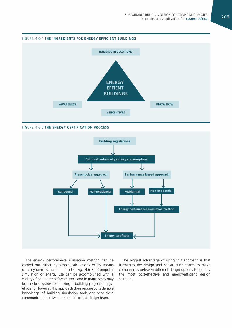
SUSTAINABLE BUILDING DESIGN FOR TROPICAL CLIMATES Principles and Applications for Eastern Africa 209
BUILDING REGULATIONS
AWARENESS KNOW HOW
+ INCENTIVES
ENERGY EFFIENT
BUILDINGS
Figure. 4.6-1 the IngredIents for energy effIcIent buIldIngs
The energy performance evaluation method can be carried out either by simple calculations or by means of a dynamic simulation model (Fig. 4.6-3). Computer simulation of energy use can be accomplished with a variety of computer software tools and in many cases may be the best guide for making a building project energy-efficient. However, this approach does require considerable knowledge of building simulation tools and very close communication between members of the design team.
The biggest advantage of using this approach is that it enables the design and construction teams to make comparisons between different design options to identify the most cost-effective and energy-efficient design solution.
Building regulations
Set limit values of primary consumption
Residential Non-Residential Residential Non-Residential
Energy certi�cate
Energy performance evaluation method
Prescriptive approach Performance based approach
Figure. 4.6-2 the energy certIfIcatIon process
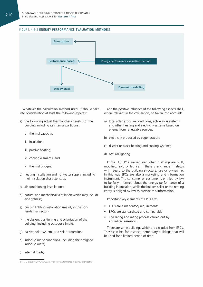
SUSTAINABLE BUILDING DESIGN FOR TROPICAL CLIMATES Principles and Applications for Eastern Africa210
Whatever the calculation method used, it should take into consideration at least the following aspects47:
a) the following actual thermal characteristics of the building including its internal partitions:
i. thermal capacity;
ii. insulation;
iii. passive heating;
iv. cooling elements; and
v. thermal bridges;
b) heating installation and hot water supply, including their insulation characteristics;
c) air-conditioning installations;
d) natural and mechanical ventilation which may include air-tightness;
e) built-in lighting installation (mainly in the non-residential sector);
f) the design, positioning and orientation of the building, including outdoor climate;
g) passive solar systems and solar protection;
h) indoor climatic conditions, including the designed indoor climate;
i) internal loads;
47 EU directive 2010/31/EC, the “Energy Performance in Buildings Directive”
and the positive influence of the following aspects shall, where relevant in the calculation, be taken into account:
a) local solar exposure conditions, active solar systems and other heating and electricity systems based on energy from renewable sources;
b) electricity produced by cogeneration;
c) district or block heating and cooling systems;
d) natural lighting.
In the EU, EPCs are required when buildings are built, modified, sold or let, i.e. if there is a change in status with regard to the building structure, use or ownership. In this way EPCs are also a marketing and information instrument. The consumer or customer is entitled by law to be fully informed about the energy performance of a building in question, while the builder, seller or the renting entity is obliged by law to provide this information.
Important key elements of EPCs are:
• EPCs are a mandatory requirement;
• EPCs are standardised and comparable;
• The rating and rating process carried out by accredited assessors.
There are some buildings which are excluded from EPCs. These can be, for instance, temporary buildings that will be used for a limited period of time.
Steady state Dynamic modelling
Energy performance evaluation method
Prescriptive
Performance based
Figure. 4.6-3 energy performance evaluatIon methods
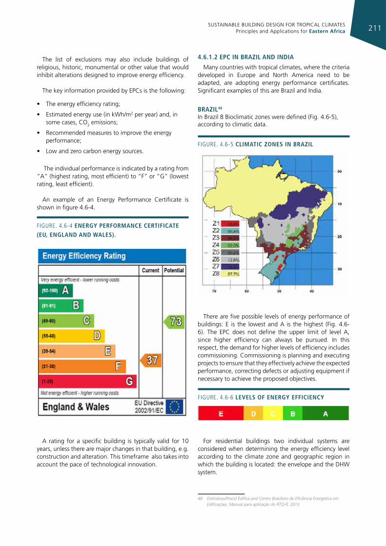
SUSTAINABLE BUILDING DESIGN FOR TROPICAL CLIMATES Principles and Applications for Eastern Africa 211
The list of exclusions may also include buildings of religious, historic, monumental or other value that would inhibit alterations designed to improve energy efficiency.
The key information provided by EPCs is the following:
• The energy efficiency rating;
• Estimated energy use (in kWh/m2 per year) and, in some cases, CO2 emissions;
• Recommended measures to improve the energy performance;
• Low and zero carbon energy sources.
The individual performance is indicated by a rating from “A” (highest rating, most efficient) to “F” or “G” (lowest rating, least efficient).
An example of an Energy Performance Certificate is shown in figure 4.6-4.
A rating for a specific building is typically valid for 10 years, unless there are major changes in that building, e.g. construction and alteration. This timeframe also takes into account the pace of technological innovation.
4.6.1.2 epc In brazIl and IndIa
Many countries with tropical climates, where the criteria developed in Europe and North America need to be adapted, are adopting energy performance certificates. Significant examples of this are Brazil and India.
brazIl48
In Brazil 8 Bioclimatic zones were defined (Fig. 4.6-5), according to climatic data.
There are five possible levels of energy performance of buildings: E is the lowest and A is the highest (Fig. 4.6-6). The EPC does not define the upper limit of level A, since higher efficiency can always be pursued. In this respect, the demand for higher levels of efficiency includes commissioning. Commissioning is planning and executing projects to ensure that they effectively achieve the expected performance, correcting defects or adjusting equipment if necessary to achieve the proposed objectives.
For residential buildings two individual systems are considered when determining the energy efficiency level according to the climate zone and geographic region in which the building is located: the envelope and the DHW system.
48 Eletrobras/Procel Edifica and Centro Brasileiro de Eficiência Energética em Edificações, Manual para aplicação do RTQ-R, 2013
Figure. 4.6-4 energy performance certIfIcate (eu, england and Wales).
Figure. 4.6-5 clImatIc zones In brazIl
Figure. 4.6-6 levels of energy effIcIency
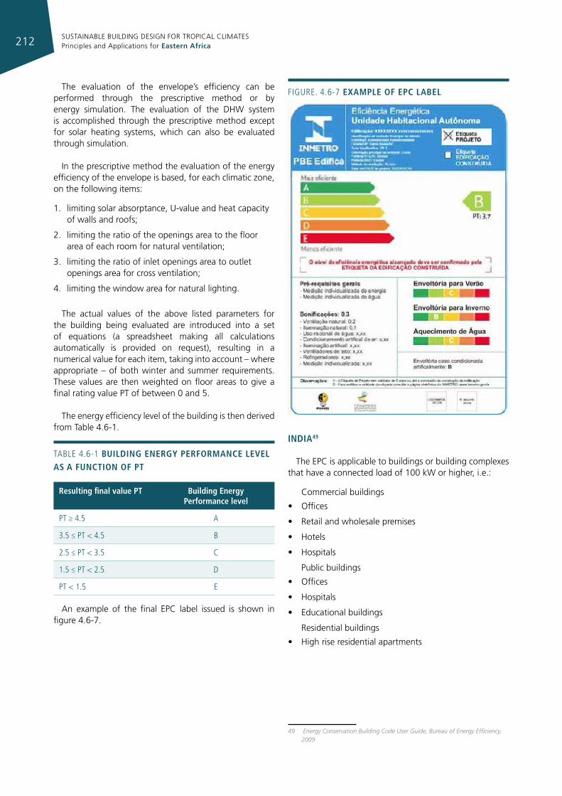
SUSTAINABLE BUILDING DESIGN FOR TROPICAL CLIMATES Principles and Applications for Eastern Africa212
The evaluation of the envelope’s efficiency can be performed through the prescriptive method or by energy simulation. The evaluation of the DHW system is accomplished through the prescriptive method except for solar heating systems, which can also be evaluated through simulation.
In the prescriptive method the evaluation of the energy efficiency of the envelope is based, for each climatic zone, on the following items:
1. limiting solar absorptance, U-value and heat capacity of walls and roofs;
2. limiting the ratio of the openings area to the floor area of each room for natural ventilation;
3. limiting the ratio of inlet openings area to outlet openings area for cross ventilation;
4. limiting the window area for natural lighting.
The actual values of the above listed parameters for the building being evaluated are introduced into a set of equations (a spreadsheet making all calculations automatically is provided on request), resulting in a numerical value for each item, taking into account – where appropriate – of both winter and summer requirements. These values are then weighted on floor areas to give a final rating value PT of between 0 and 5.
The energy efficiency level of the building is then derived from Table 4.6-1.
TABLe 4.6-1 buIldIng energy performance level as a functIon of pt
resulting final value pt building energy performance level
PT ≥ 4.5 A
3.5 ≤ PT < 4.5 B
2.5 ≤ PT < 3.5 C
1.5 ≤ PT < 2.5 D
PT < 1.5 e
An example of the final EPC label issued is shown in figure 4.6-7.
IndIa49
The EPC is applicable to buildings or building complexes that have a connected load of 100 kW or higher, i.e.:
Commercial buildings
• Offices
• Retail and wholesale premises
• Hotels
• Hospitals
Public buildings
• Offices
• Hospitals
• Educational buildings
Residential buildings
• High rise residential apartments
49 Energy Conservation Building Code User Guide, Bureau of Energy Efficiency, 2009
Figure. 4.6-7 example of epc label
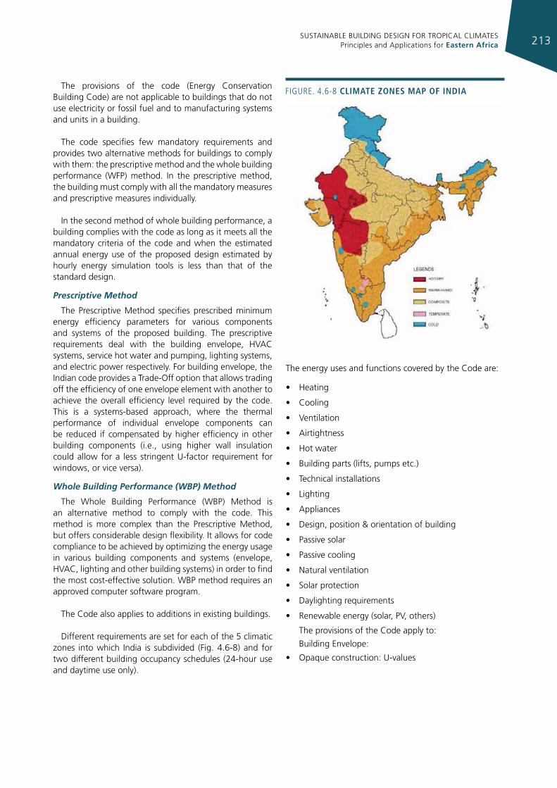
SUSTAINABLE BUILDING DESIGN FOR TROPICAL CLIMATES Principles and Applications for Eastern Africa 213
The provisions of the code (Energy Conservation Building Code) are not applicable to buildings that do not use electricity or fossil fuel and to manufacturing systems and units in a building.
The code specifies few mandatory requirements and provides two alternative methods for buildings to comply with them: the prescriptive method and the whole building performance (WFP) method. In the prescriptive method, the building must comply with all the mandatory measures and prescriptive measures individually.
In the second method of whole building performance, a building complies with the code as long as it meets all the mandatory criteria of the code and when the estimated annual energy use of the proposed design estimated by hourly energy simulation tools is less than that of the standard design.
Prescriptive Method
The Prescriptive Method specifies prescribed minimum energy efficiency parameters for various components and systems of the proposed building. The prescriptive requirements deal with the building envelope, HVAC systems, service hot water and pumping, lighting systems, and electric power respectively. For building envelope, the Indian code provides a Trade-Off option that allows trading off the efficiency of one envelope element with another to achieve the overall efficiency level required by the code. This is a systems-based approach, where the thermal performance of individual envelope components can be reduced if compensated by higher efficiency in other building components (i.e., using higher wall insulation could allow for a less stringent U-factor requirement for windows, or vice versa).
Whole Building Performance (WBP) Method
The Whole Building Performance (WBP) Method is an alternative method to comply with the code. This method is more complex than the Prescriptive Method, but offers considerable design flexibility. It allows for code compliance to be achieved by optimizing the energy usage in various building components and systems (envelope, HVAC, lighting and other building systems) in order to find the most cost-effective solution. WBP method requires an approved computer software program.
The Code also applies to additions in existing buildings.
Different requirements are set for each of the 5 climatic zones into which India is subdivided (Fig. 4.6-8) and for two different building occupancy schedules (24-hour use and daytime use only).
The energy uses and functions covered by the Code are:
• Heating
• Cooling
• Ventilation
• Airtightness
• Hot water
• Building parts (lifts, pumps etc.)
• Technical installations
• Lighting
• Appliances
• Design, position & orientation of building
• Passive solar
• Passive cooling
• Natural ventilation
• Solar protection
• Daylighting requirements
• Renewable energy (solar, PV, others)
The provisions of the Code apply to:
Building Envelope:
• Opaque construction: U-values
Figure. 4.6-8 clImate zones map of IndIa
SUSTAINABLE BUILDING DESIGN FOR TROPICAL CLIMATES Principles and Applications for Eastern Africa214
• Fenestration: maximum area weighted U-value and SHGC according to window-to-wall ratios (WWR) visible light transmittance, and air leakage
• Skylights: maximum U-values and SHGC
• Overhang and side-fin
• Envelope sealing details
• Cool roof with slopes of less than 20°: solar reflectance and emittance
HVAC:
• Systems and equipment and controls
• Economizer details
• Variable speed drives
• Piping insulation
• Duct sealing
• Insulation type and location
• HVAC balancing Service Hot Water and Pumping:
• Solar water heating system details
• Equipment efficiency
• Supplementary water heating systems
• Piping insulation
Lighting:
• Schedules
• Automatic lighting shutoff
• Occupancy sensors and other lighting control details
• Lamp efficacy for exterior lamps
Electrical Power:
• Transformer losses, motor efficiencies, and power factor correction devices
• Metering and monitoring system
• Power distribution systems
For each item limit values are provided and compliance forms have to be submitted to obtain the EPC with the Prescriptive Method. If the WBP approach is adopted, two simulations must be run: one with the actual building’s parameters and one with the standard building parameters (i.e. the ones required in the prescriptive approach). The actual building’s simulated energy consumption must be lower or equal to that of the simulated standard one to comply.
4.6.2 green buIldIng raTIng sysTems
Green Building Rating Systems (GBRSs) are standardised methods or tools for the assessment of the wider environmental performance of buildings; they are voluntary market-based instruments.
GBRSs use a holistic approach that goes beyond the approach underlying Energy Performance Certificates (EPCs), even though some similarities exist. GBRSs incorporate an energy performance evaluation of buildings, but at the same time also take into consideration resource efficiency, and the overall environmental impact of a building as well as its life cycle.
The assessment of energy and resource efficiency is a central objective of GBRSs. Resource efficiency refers to the management and optimisation of material flows within a building, and especially to the minimisation, re-use and re-cycling of solid and liquid wastes. Rainwater harvesting and the use of renewable energies on-site is an example of the utilisation of natural and renewable sources of energy and materials. The optimal rating for a green building should be equivalent to a minimal ecological footprint.
Most GBRSs today follow a Live Cycle Assessment (LCA) approach that means the assessment considers the entire life-cycle of a building from “cradle to grave”. It is important for the optimisation of the environmental performance of buildings to consider not just the building as it stands and as it is used, but also its production and its disposal (or demolition). The LCA approach includes therefore the design of the building, the site selection, the construction, the operation and maintenance, renovation, demolition, the selection and optimal use of building materials etc. However, the optimisation of operation and maintenance may be considered the most important feature of GBRS.
GBRS help and provide guidance in improving energy and resource efficiency of buildings as well as their environmental performance. The assessment of a building by means of GBRS can, however, be a significant cost factor. The rating systems are operated by non-profit and non-governmental organisations. The assessment as well as the certification is, however, not free of charge. The improvements and technical interventions necessary for achieving a high rating normally require additional investments as compared to the business-as-usual scenario. Improved efficiency, on the other hand, can and will translate into cost savings for operation and an increased market value of a building (for retail or lending).
GBRSs typically comprise a number of rating schemes that are tailored to the assessment of specific building types, for instance community housing and compounds, education facilities, health care facilities, private or individual homes, industrial buildings, multi-residential buildings, offices, prisons, retail facilities etc. (example: BREEAM, UK). International schemes of GBRSs offer the opportunity for their adoption in different countries and under conditions other than those of the country where the GBRS originates. GBRSs are hence not only building type specific (specific rating schemes), but are also linked to particular conditions in the countries they have been
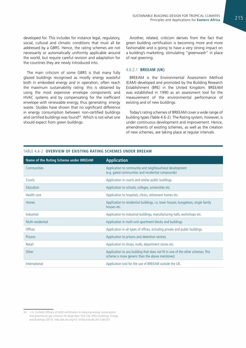
SUSTAINABLE BUILDING DESIGN FOR TROPICAL CLIMATES Principles and Applications for Eastern Africa 215
developed for. This includes for instance legal, regulatory, social, cultural and climatic conditions that must all be addressed by a GBRS. Hence, the rating schemes are not necessarily or automatically uniformly applicable around the world, but require careful revision and adaptation for the countries they are newly introduced into.
The main criticism of some GBRS is that many fully glazed buildings recognised as mostly energy wasteful both in embodied energy and in operation, often reach the maximum sustainability rating: this is obtained by using the most expensive envelope components and HVAC systems and by compensating for the inefficient envelope with renewable energy, thus generating energy waste. Studies have shown that no significant difference in energy consumption between non-certified buildings and certified buildings was found50. Which is not what one should expect from green buildings.
50 J.H. Scofield, Efficacy of LEED-certification in reducing energy consumption and greenhouse gas emission for large New York City office buildings, Energy and Buildings (2013), http://dx.doi.org/10.1016/j.enbuild.2013.08.032
Another, related, criticism derives from the fact that green building certification is becoming more and more fashionable and is going to have a very strong impact on a building’s marketing, stimulating “greenwash” in place of real greening.
4.6.2.1 breeam (uk)
BREEAM is the Environmental Assessment Method (EAM) developed and promoted by the Building Research Establishment (BRE) in the United Kingdom. BREEAM was established in 1990 as an assessment tool for the measurement of the environmental performance of existing and of new buildings.
Today’s rating schemes of BREEAM cover a wide range of building types (Table 4.6-2). The Rating system, however, is under continuous development and improvement. Hence, amendments of existing schemes, as well as the creation of new schemes, are taking place at regular intervals.
name of the rating scheme under breeam application
Communities Application to community and neighbourhood development (e.g. gated communities and residential compounds)
Courts Application in courts and similar public buildings
education Application to schools, colleges, universities etc.
Health care Application to hospitals, clinics, retirement homes etc.
Homes Application to residential buildings, i.e. town houses, bungalows, single family houses etc.
industrial Application to industrial buildings, manufacturing halls, workshops etc.
Multi-residential Application in multi-unit apartment blocks and buildings.
Offices Application in all types of offices, including private and public buildings.
Prisons Application to prisons and detention centres.
retail Application to shops, malls, department stores etc.
Other Application to any building that does not fit in one of the other schemes. This scheme is more generic than the above mentioned.
international Application tool for the use of BreeAM outside the uK.
TABLe 4.6-2 overvIeW of exIstIng ratIng schemes under breeam
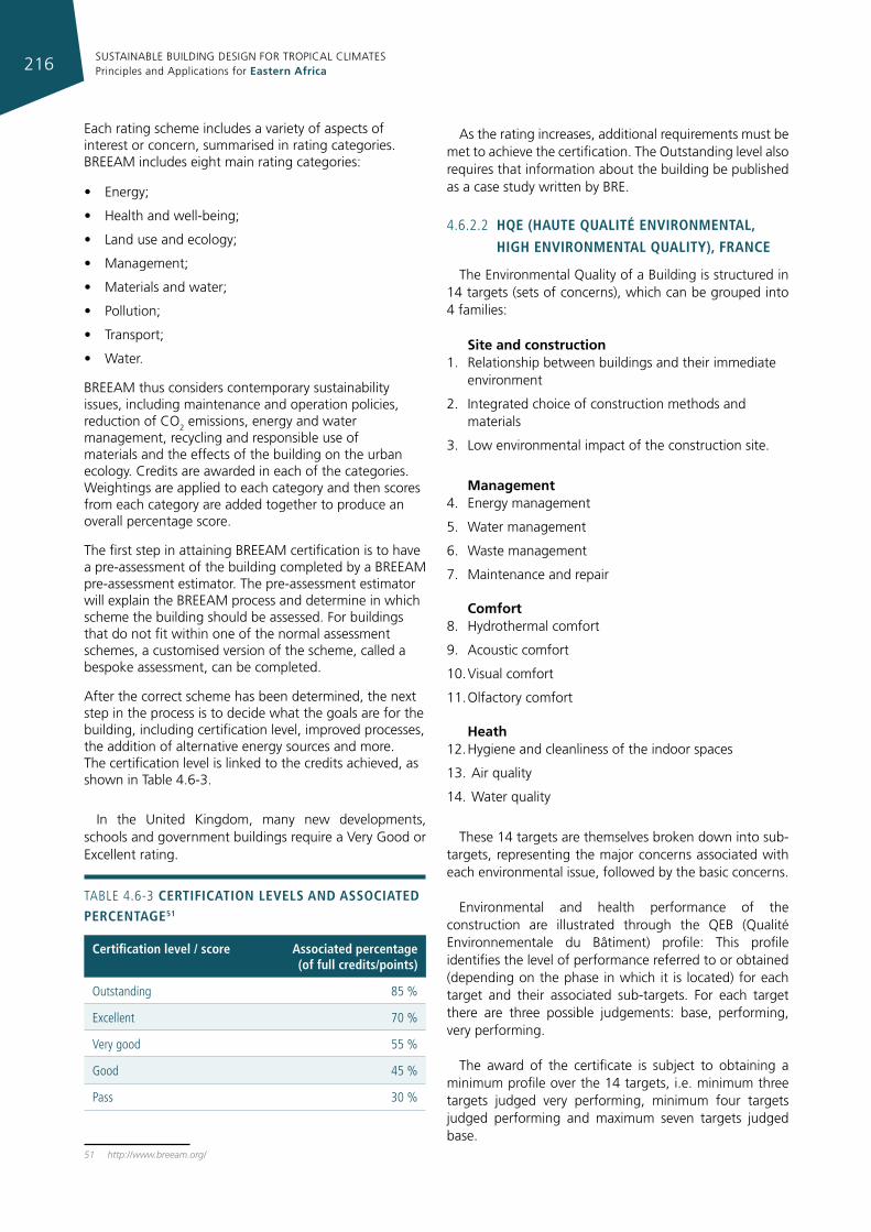
SUSTAINABLE BUILDING DESIGN FOR TROPICAL CLIMATES Principles and Applications for Eastern Africa216
Each rating scheme includes a variety of aspects of interest or concern, summarised in rating categories. BREEAM includes eight main rating categories:
• Energy;
• Health and well-being;
• Land use and ecology;
• Management;
• Materials and water;
• Pollution;
• Transport;
• Water.
BREEAM thus considers contemporary sustainability issues, including maintenance and operation policies, reduction of CO2 emissions, energy and water management, recycling and responsible use of materials and the effects of the building on the urban ecology. Credits are awarded in each of the categories. Weightings are applied to each category and then scores from each category are added together to produce an overall percentage score.
The first step in attaining BREEAM certification is to have a pre-assessment of the building completed by a BREEAM pre-assessment estimator. The pre-assessment estimator will explain the BREEAM process and determine in which scheme the building should be assessed. For buildings that do not fit within one of the normal assessment schemes, a customised version of the scheme, called a bespoke assessment, can be completed.
After the correct scheme has been determined, the next step in the process is to decide what the goals are for the building, including certification level, improved processes, the addition of alternative energy sources and more. The certification level is linked to the credits achieved, as shown in Table 4.6-3.
In the United Kingdom, many new developments, schools and government buildings require a Very Good or Excellent rating.
TABLe 4.6-3 certIfIcatIon levels and assocIated percentage51
certification level / score associated percentage (of full credits/points)
Outstanding 85 %
excellent 70 %
Very good 55 %
good 45 %
Pass 30 %
51 http://www.breeam.org/
As the rating increases, additional requirements must be met to achieve the certification. The Outstanding level also requires that information about the building be published as a case study written by BRE.
4.6.2.2 hqe (haute qualIté envIronmental,
hIgh envIronmental qualIty), france
The Environmental Quality of a Building is structured in 14 targets (sets of concerns), which can be grouped into 4 families:
Site and construction1. Relationship between buildings and their immediate
environment
2. Integrated choice of construction methods and materials
3. Low environmental impact of the construction site.
Management4. Energy management
5. Water management
6. Waste management
7. Maintenance and repair
Comfort8. Hydrothermal comfort
9. Acoustic comfort
10. Visual comfort
11. Olfactory comfort
Heath12. Hygiene and cleanliness of the indoor spaces
13. Air quality
14. Water quality
These 14 targets are themselves broken down into sub-targets, representing the major concerns associated with each environmental issue, followed by the basic concerns.
Environmental and health performance of the construction are illustrated through the QEB (Qualité Environnementale du Bâtiment) profile: This profile identifies the level of performance referred to or obtained (depending on the phase in which it is located) for each target and their associated sub-targets. For each target there are three possible judgements: base, performing, very performing.
The award of the certificate is subject to obtaining a minimum profile over the 14 targets, i.e. minimum three targets judged very performing, minimum four targets judged performing and maximum seven targets judged base.
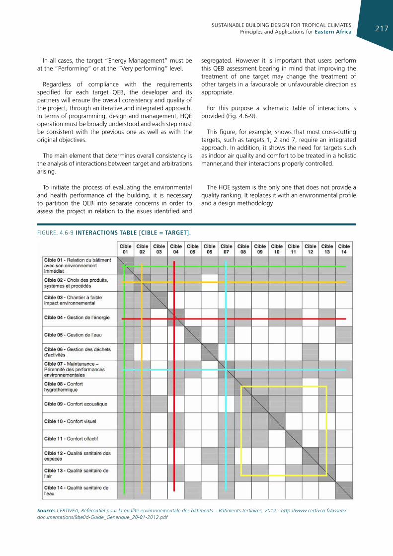
SUSTAINABLE BUILDING DESIGN FOR TROPICAL CLIMATES Principles and Applications for Eastern Africa 217
In all cases, the target “Energy Management” must be at the “Performing” or at the “Very performing” level.
Regardless of compliance with the requirements specified for each target QEB, the developer and its partners will ensure the overall consistency and quality of the project, through an iterative and integrated approach. In terms of programming, design and management, HQE operation must be broadly understood and each step must be consistent with the previous one as well as with the original objectives.
The main element that determines overall consistency is the analysis of interactions between target and arbitrations arising.
To initiate the process of evaluating the environmental and health performance of the building, it is necessary to partition the QEB into separate concerns in order to assess the project in relation to the issues identified and
segregated. However it is important that users perform this QEB assessment bearing in mind that improving the treatment of one target may change the treatment of other targets in a favourable or unfavourable direction as appropriate.
For this purpose a schematic table of interactions is provided (Fig. 4.6-9).
This figure, for example, shows that most cross-cutting targets, such as targets 1, 2 and 7, require an integrated approach. In addition, it shows the need for targets such as indoor air quality and comfort to be treated in a holistic manner,and their interactions properly controlled.
The HQE system is the only one that does not provide a quality ranking. It replaces it with an environmental profile and a design methodology.
Figure. 4.6-9 InteractIons table [cIble = target].
Source: CERTIVEA, Référentiel pour la qualité environnementale des bâtiments – Bâtiments tertiaires, 2012 - http://www.certivea.fr/assets/documentations/9be0d-Guide_Generique_20-01-2012.pdf
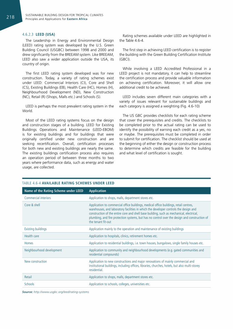
SUSTAINABLE BUILDING DESIGN FOR TROPICAL CLIMATES Principles and Applications for Eastern Africa218
4.6.2.3 leed (usa)
The Leadership in Energy and Environmental Design (LEED) rating system was developed by the U.S. Green Building Council (USGBC) between 1998 and 2000 and drew significantly from the BREEAM system. Like BREEAM, LEED also saw a wider application outside the USA, its country of origin.
The first LEED rating system developed was for new construction. Today, a variety of rating schemes exist under LEED: Commercial Interiors (CI), Core and Shell (CS), Existing Buildings (EB), Health Care (HC), Homes (H), Neighbourhood Development (ND), New Construction (NC), Retail (R) (Shops, Malls etc.) and Schools (S).
LEED is perhaps the most prevalent rating system in the World.
Most of the LEED rating systems focus on the design and construction stages of a building. LEED for Existing Buildings Operations and Maintenance (LEED-EBOM) is for existing buildings and for buildings that were originally certified under new construction and are seeking recertification. Overall, certification processes for both new and existing buildings are nearly the same. The existing buildings certification process also requires an operation period of between three months to two years where performance data, such as energy and water usage, are collected.
Rating schemes available under LEED are highlighted in the Table 4.6-4.
The first step in achieving LEED certification is to register the building with the Green Building Certification Institute (GBCI).
While involving a LEED Accredited Professional in a LEED project is not mandatory, it can help to streamline the certification process and provide valuable information on achieving certification. Moreover, it will allow one additional credit to be achieved.
LEED includes seven different main categories with a variety of issues relevant for sustainable buildings and each category is assigned a weighting (Fig. 4.6-10)
The US GBC provides checklists for each rating scheme that cover the prerequisites and credits. The checklists to be completed prior to the actual rating can be used to identify the possibility of earning each credit as a yes, no or maybe. The prerequisites must be completed in order to submit for certification. The checklist should be used at the beginning of either the design or construction process to determine which credits are feasible for the building and what level of certification is sought.
name of the rating scheme under leed application
Commercial interiors Application to shops, malls, department stores etc.
Core & shell Application to commercial office buildings, medical office buildings, retail centres, warehouses, and laboratory facilities in which the developer controls the design and construction of the entire core and shell base building, such as mechanical, electrical, plumbing, and fire protection systems, but has no control over the design and construction of the tenant fit-out
existing buildings Application mainly to the operation and maintenance of existing buildings
Health care Application to hospitals, clinics, retirement homes etc.
Homes Application to residential buildings, i.e. town houses, bungalows, single family houses etc.
Neighbourhood development Application to community and neighbourhood developments (e.g. gated communities and residential compounds)
New construction Application to new constructions and major renovations of mainly commercial and institutional buildings, including offices, libraries, churches, hotels, but also multi-storey residential.
retail Application to shops, malls, department stores etc.
Schools Application to schools, colleges, universities etc.
TABLe 4.6-4 avaIlable ratIng schemes under leed
Source: http://www.usgbc.org/leed/rating-systems
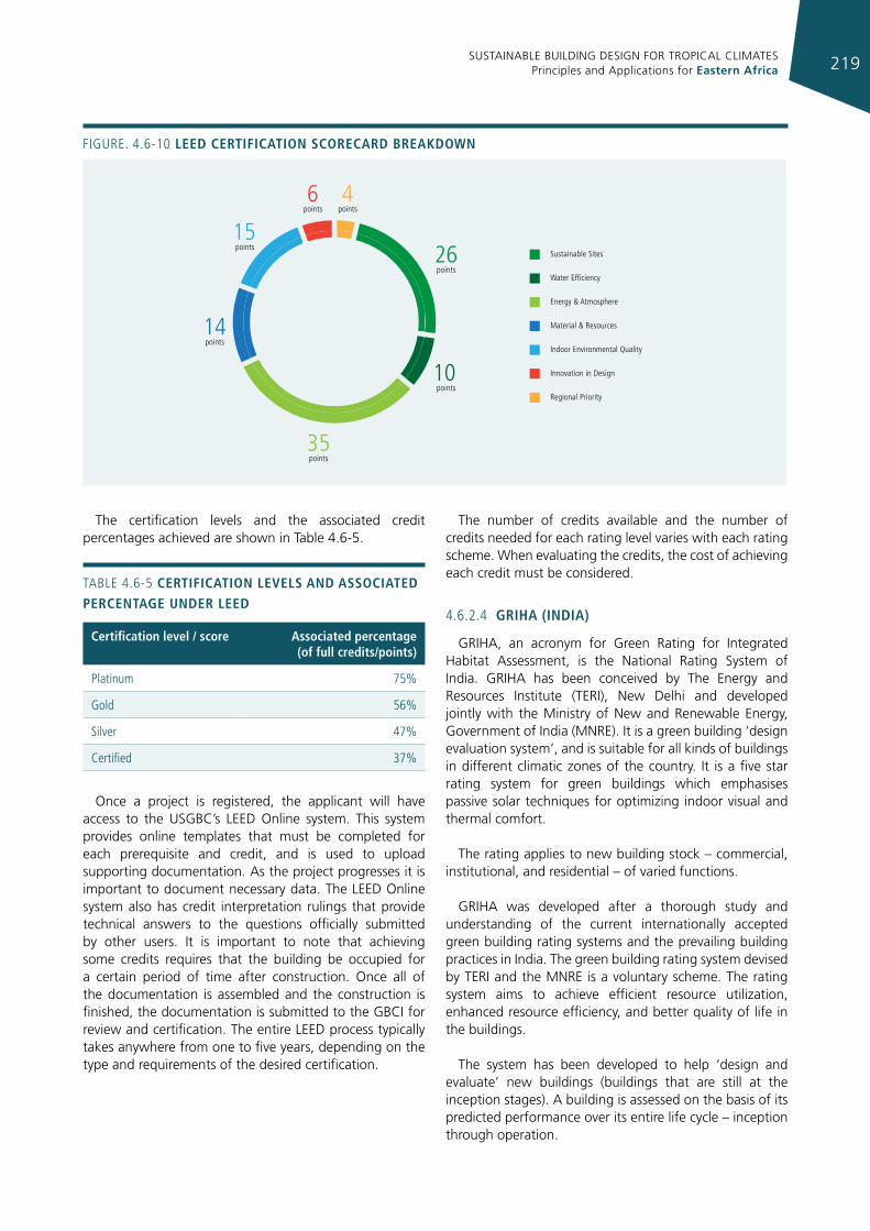
SUSTAINABLE BUILDING DESIGN FOR TROPICAL CLIMATES Principles and Applications for Eastern Africa 219
Sustainable Sites
Water Efficiency
Energy & Atmosphere
Material & Resources
Indoor Environmental Quality
Innovation in Design
Regional Priority
15points
14points
6points
4points
26points
10points
35points
Figure. 4.6-10 leed certIfIcatIon scorecard breakdoWn
The certification levels and the associated credit percentages achieved are shown in Table 4.6-5.
TABLe 4.6-5 certIfIcatIon levels and assocIated percentage under leed
certification level / score associated percentage (of full credits/points)
Platinum 75%
gold 56%
Silver 47%
Certified 37%
Once a project is registered, the applicant will have access to the USGBC’s LEED Online system. This system provides online templates that must be completed for each prerequisite and credit, and is used to upload supporting documentation. As the project progresses it is important to document necessary data. The LEED Online system also has credit interpretation rulings that provide technical answers to the questions officially submitted by other users. It is important to note that achieving some credits requires that the building be occupied for a certain period of time after construction. Once all of the documentation is assembled and the construction is finished, the documentation is submitted to the GBCI for review and certification. The entire LEED process typically takes anywhere from one to five years, depending on the type and requirements of the desired certification.
The number of credits available and the number of credits needed for each rating level varies with each rating scheme. When evaluating the credits, the cost of achieving each credit must be considered.
4.6.2.4 grIha (IndIa)
GRIHA, an acronym for Green Rating for Integrated Habitat Assessment, is the National Rating System of India. GRIHA has been conceived by The Energy and Resources Institute (TERI), New Delhi and developed jointly with the Ministry of New and Renewable Energy, Government of India (MNRE). It is a green building ‘design evaluation system’, and is suitable for all kinds of buildings in different climatic zones of the country. It is a five star rating system for green buildings which emphasises passive solar techniques for optimizing indoor visual and thermal comfort.
The rating applies to new building stock – commercial, institutional, and residential – of varied functions.
GRIHA was developed after a thorough study and understanding of the current internationally accepted green building rating systems and the prevailing building practices in India. The green building rating system devised by TERI and the MNRE is a voluntary scheme. The rating system aims to achieve efficient resource utilization, enhanced resource efficiency, and better quality of life in the buildings.
The system has been developed to help ‘design and evaluate’ new buildings (buildings that are still at the inception stages). A building is assessed on the basis of its predicted performance over its entire life cycle – inception through operation.
SUSTAINABLE BUILDING DESIGN FOR TROPICAL CLIMATES Principles and Applications for Eastern Africa220
The stages of the life cycle that have been identified for evaluation are:
• Pre-construction stage (intra- and inter-site issues like proximity to public transport, type of soil, kind of land, where the property is located, the flora and fauna on the land before construction activity starts, the natural landscape and land features);
• Building planning and construction stage (issues of resource conservation and reduction in resource demand, resource utilization efficiency, resource recovery and reuse, and provisions for occupant health and well being). The prime resources that are considered in this section are land, water, energy, air, and green cover;
• Building operation and maintenance stage (issues of operation and maintenance of building systems and processes, monitoring and recording of energy consumption, and occupant health and wellbeing, and also issues that affect the global and local environment).
On a broader scale, this system, along with the activities and processes that lead up to it, will benefit the community at large with the improvement of the environment by a reduction in greenhouse gas emissions, a reduction in energy consumption and the use of natural resources.
The GRIHA rating system consists of 34 criteria divided into four categories: site selection and site planning; building planning and construction; building operation and maintenance; and innovation. Eight of these 34 criteria are mandatory; four are partly mandatory, while the rest are optional. Each criterion has a number of points assigned to it. It means that a project intending to meet the criterion would qualify for the points. Different levels of certification (one star to five stars) are awarded, based on the number of points earned. The minimum points/percentage required for certification is 50.
The evaluation process under GRIHA includes nine distinct steps:
1. Registration;
2. Submission of documentation;
3. Preliminary evaluation by ADaRSH (Association for Development and Research of Sustainable Habitats52) technical team;
4. Evaluation by panel of experts;
5. Preliminary rating with comments sent to project team,
52 It is an independent platform for the interaction on scientific and administrative issues related to sustainable habitats in the Indian context. It was founded jointly by MNRE and TERI along with experts in the fields related to sustainability of built environment from across the country.
6. Final submission of documents;
7. Final evaluation by panel of experts;
8. Approval of rating by advisory committee;
9. Award of rating.
After online submission of documents, the preliminary evaluation is carried out by a team of professionals and experts from ADaRSH. Documentation should be complete in all respects for all criteria attempted. The ADaRSH team reviews the mandatory criteria and rejects the project in the event of non-compliance with such criteria, and then evaluates the optional criteria and estimates the total number of achievable points. All compliance documents are checked and vetted.
The evaluation summary report is sent to members of the evaluation committee for GRIHA comprising renowned experts in each sector, landscape architecture, lighting and HVAC design, renewable energy, water and waste management, and building materials. The evaluation committee members examine the points estimated by the technical team. The evaluation committee then independently reviews the documents for the award of points. The evaluation committee may use the evaluation summary report submitted by the technical team as a guiding document. The evaluation committee awards provisional points and also comments on specific criteria, if required. The evaluation report is sent to the project proponent for review and, if desired, for steps be taken to increase the score. The client is given a period of one month to resubmit the document with the necessary modifications /additions. The resubmitted document comprises only the additional documents / information desired in the evaluation report. The resubmitted documents is again put through the vetting process described above. The evaluation committee then awards the final score. The final score is presented to an advisory committee comprising eminent personalities and renowned professionals in the field for approval and award of rating. The rating is valid for a period of five years from the date of commissioning of the building. ADaRSH reserves the right to undertake a random audit of any criteria for which points have been awarded. Great emphasis is placed on the efficient use and conservation of resources, health, bioclimatic comfort and the protection of living organisms.
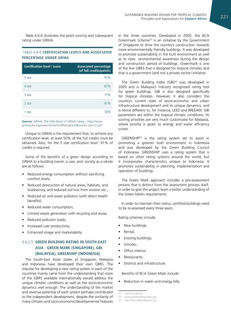
SUSTAINABLE BUILDING DESIGN FOR TROPICAL CLIMATES Principles and Applications for Eastern Africa 221
Table 4.6-6 illustrates the point scoring and subsequent rating under GRIHA.
TABLe 4.6-6 certIfIcatIon levels and assocIated percentage under grIha
certification level / score associated percentage (of full credits/points)
5 star 91%
4 star 81%
3 star 71%
2 star 61%
1 star 50%
Source: GRIHA, The little Book of GRIHA rating - http://www.grihaindia.org/static/Griha%20Rating%20Booklet_Dec12.pdf
Unique to GRIHA is the requirement that, to achieve any certification level, at least 50% of the full credits must be obtained. Also, for the 5 star certification level 91% of credits is required.
Some of the benefits of a green design according to GRIHA to a building owner, a user, and society as a whole are as follows:
• Reduced energy consumption without sacrificing comfort levels;
• Reduced destruction of natural areas, habitats, and biodiversity, and reduced soil loss from erosion etc.;
• Reduced air and water pollution (with direct health benefits);
• Reduced water consumption;
• Limited waste generation with recycling and reuse;
• Reduced pollution loads;
• Increased user productivity;
• Enhanced image and marketability.
4.6.2.5 green buIldIng ratIng In south-east
asIa - green mark (sIngapore), gbI
(malaysIa), greenshIp (IndonesIa)The South-East Asian states of Singapore, Malaysia
and Indonesia have developed their own GBRS. The impulse for developing a new rating system in each of the countries mainly came from the understanding that none of the GBRS available internationally would address the unique climatic conditions as well as the socio-economic dynamics well enough. The understanding of the market and revenue potential of each system perhaps contributed to the independent development, despite the similarity of many climatic and socio-economic/developmental features
in the three countries. Developed in 2005, the BCA Greenmark Scheme53 is an initiative by the Government of Singapore to drive the country’s construction towards more environmentally friendly buildings. It was developed to promote sustainability in the built environment as well as to raise environmental awareness during the design and construction period of buildings. Greenmark is one of the few GBRS that is designed for tropical climates and that is a government (and not a private sector) initiative.
The Green Building Index (GBI)54 was developed in 2009 and is Malaysia’s industry recognised rating tool for green buildings. GBI is also designed specifically for tropical climates. However, it also considers the country’s current state of socio-economic and urban infrastructure development and its unique dynamics, and is hence different to, for instance, LEED and BREEAM. GBI parameters are within the tropical climatic conditions. Its scoring priorities are very much customized for Malaysia, where priority is given to energy and water efficiency scores.
GREENSHIP55 is the rating system set to assist in promoting a greener built environment in Indonesia and was developed by the Green Building Council of Indonesia. GREENSHIP uses a rating system that is based on other rating systems around the world, but it incorporates characteristics unique to Indonesia. It promotes sustainability in planning, implementation and operation of buildings.
The Green Mark approach includes a pre-assessment process that is distinct from the assessment process itself, in order to give the project team a better understanding of the Green Marks requirements.
In order to maintain their status, certified buildings need to be re-assessed every three years.
Rating schemes include:
• New buildings;
• Rental;
• Existing buildings;
• Schools;
• Office interior;
• Restaurants;
• Districts and infrastructure.
Benefits of BCA Green Mark include:
• Reduction in water and energy bills;
53 www.bca.gov.sg54 www.greenbuildingindex.org55 http://www.gbcindonesia.org
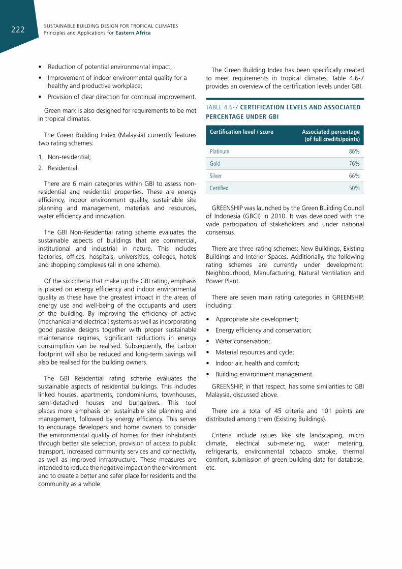
SUSTAINABLE BUILDING DESIGN FOR TROPICAL CLIMATES Principles and Applications for Eastern Africa222
• Reduction of potential environmental impact;
• Improvement of indoor environmental quality for a healthy and productive workplace;
• Provision of clear direction for continual improvement.
Green mark is also designed for requirements to be met in tropical climates.
The Green Building Index (Malaysia) currently features two rating schemes:
1. Non-residential;
2. Residential.
There are 6 main categories within GBI to assess non-residential and residential properties. These are energy efficiency, indoor environment quality, sustainable site planning and management, materials and resources, water efficiency and innovation.
The GBI Non-Residential rating scheme evaluates the sustainable aspects of buildings that are commercial, institutional and industrial in nature. This includes factories, offices, hospitals, universities, colleges, hotels and shopping complexes (all in one scheme).
Of the six criteria that make up the GBI rating, emphasis is placed on energy efficiency and indoor environmental quality as these have the greatest impact in the areas of energy use and well-being of the occupants and users of the building. By improving the efficiency of active (mechanical and electrical) systems as well as incorporating good passive designs together with proper sustainable maintenance regimes, significant reductions in energy consumption can be realised. Subsequently, the carbon footprint will also be reduced and long-term savings will also be realised for the building owners.
The GBI Residential rating scheme evaluates the sustainable aspects of residential buildings. This includes linked houses, apartments, condominiums, townhouses, semi-detached houses and bungalows. This tool places more emphasis on sustainable site planning and management, followed by energy efficiency. This serves to encourage developers and home owners to consider the environmental quality of homes for their inhabitants through better site selection, provision of access to public transport, increased community services and connectivity, as well as improved infrastructure. These measures are intended to reduce the negative impact on the environment and to create a better and safer place for residents and the community as a whole.
The Green Building Index has been specifically created to meet requirements in tropical climates. Table 4.6-7 provides an overview of the certification levels under GBI.
TABLe 4.6-7 certIfIcatIon levels and assocIated percentage under gbI
certification level / score associated percentage (of full credits/points)
Platinum 86%
gold 76%
Silver 66%
Certified 50%
GREENSHIP was launched by the Green Building Council of Indonesia (GBCI) in 2010. It was developed with the wide participation of stakeholders and under national consensus.
There are three rating schemes: New Buildings, Existing Buildings and Interior Spaces. Additionally, the following rating schemes are currently under development: Neighbourhood, Manufacturing, Natural Ventilation and Power Plant.
There are seven main rating categories in GREENSHIP, including:
• Appropriate site development;
• Energy efficiency and conservation;
• Water conservation;
• Material resources and cycle;
• Indoor air, health and comfort;
• Building environment management.
GREENSHIP, in that respect, has some similarities to GBI Malaysia, discussed above.
There are a total of 45 criteria and 101 points are distributed among them (Existing Buildings).
Criteria include issues like site landscaping, micro climate, electrical sub-metering, water metering, refrigerants, environmental tobacco smoke, thermal comfort, submission of green building data for database, etc.
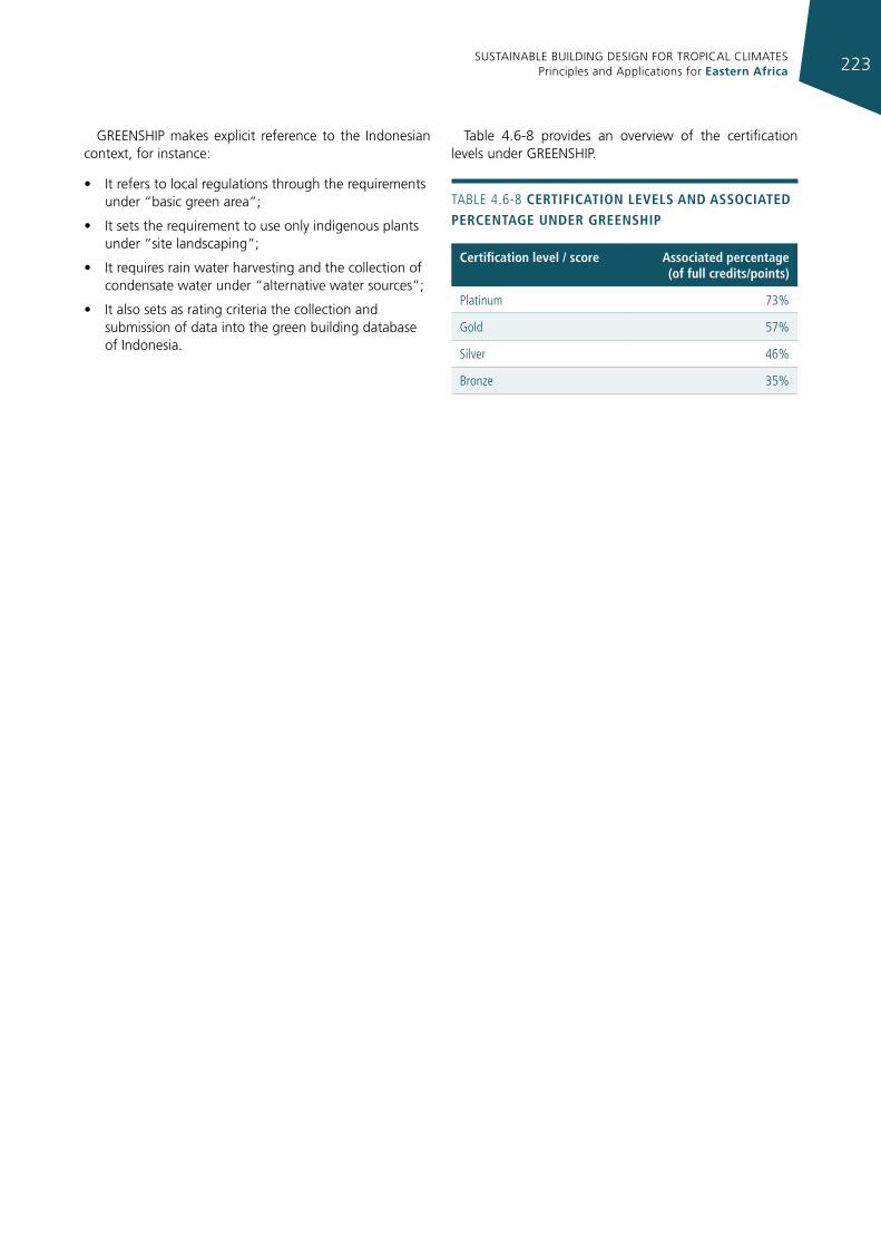
SUSTAINABLE BUILDING DESIGN FOR TROPICAL CLIMATES Principles and Applications for Eastern Africa 223
GREENSHIP makes explicit reference to the Indonesian context, for instance:
• It refers to local regulations through the requirements under “basic green area”;
• It sets the requirement to use only indigenous plants under “site landscaping”;
• It requires rain water harvesting and the collection of condensate water under “alternative water sources”;
• It also sets as rating criteria the collection and submission of data into the green building database of Indonesia.
Table 4.6-8 provides an overview of the certification levels under GREENSHIP.
TABLe 4.6-8 certIfIcatIon levels and assocIated percentage under greenshIp
certification level / score associated percentage (of full credits/points)
Platinum 73%
gold 57%
Silver 46%
Bronze 35%
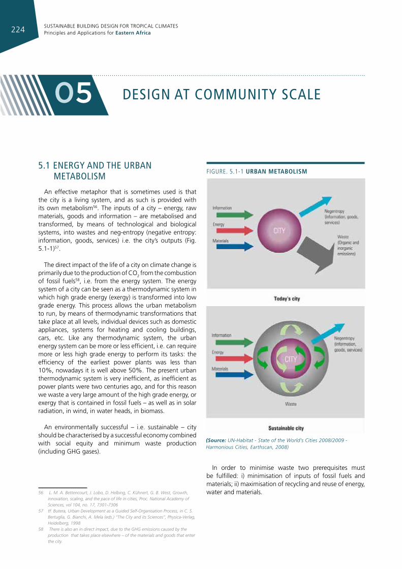
SUSTAINABLE BUILDING DESIGN FOR TROPICAL CLIMATES Principles and Applications for Eastern Africa224
desIgn aT communITy scale05
5.1 energy and The urban meTabolIsm
An effective metaphor that is sometimes used is that the city is a living system, and as such is provided with its own metabolism56. The inputs of a city – energy, raw materials, goods and information – are metabolised and transformed, by means of technological and biological systems, into wastes and neg-entropy (negative entropy: information, goods, services) i.e. the city’s outputs (Fig. 5.1-1)57.
The direct impact of the life of a city on climate change is primarily due to the production of CO2 from the combustion of fossil fuels58, i.e. from the energy system. The energy system of a city can be seen as a thermodynamic system in which high grade energy (exergy) is transformed into low grade energy. This process allows the urban metabolism to run, by means of thermodynamic transformations that take place at all levels, individual devices such as domestic appliances, systems for heating and cooling buildings, cars, etc. Like any thermodynamic system, the urban energy system can be more or less efficient, i.e. can require more or less high grade energy to perform its tasks: the efficiency of the earliest power plants was less than 10%, nowadays it is well above 50%. The present urban thermodynamic system is very inefficient, as inefficient as power plants were two centuries ago, and for this reason we waste a very large amount of the high grade energy, or exergy that is contained in fossil fuels – as well as in solar radiation, in wind, in water heads, in biomass.
An environmentally successful – i.e. sustainable – city should be characterised by a successful economy combined with social equity and minimum waste production (including GHG gases).
56 L. M. A. Bettencourt, J. Lobo, D. Helbing, C. Kühnert, G. B. West, Growth, innovation, scaling, and the pace of life in cities, Proc. National Academy of Sciences, vol 104, no. 17, 7301-7306
57 tF. Butera, Urban Development as a Guided Self-Organisation Process, in C. S. Bertuglia, G. Bianchi, A. Mela (eds.) “The City and its Sciences”, Physica-Verlag, Heidelberg, 1998
58 There is also an in direct impact, due to the GHG emissions caused by the production that takes place elsewhere – of the materials and goods that enter the city.
In order to minimise waste two prerequisites must be fulfilled: i) minimisation of inputs of fossil fuels and materials; ii) maximisation of recycling and reuse of energy, water and materials.
Figure. 5.1-1 urban metabolIsm
(Source: UN-Habitat - State of the World’s Cities 2008/2009 - Harmonious Cities, Earthscan, 2008)
SUSTAINABLE BUILDING DESIGN FOR TROPICAL CLIMATES Principles and Applications for Eastern Africa 225
To fulfil these prerequisites, the urban metabolism must be a circular metabolism, not the linear one that has characterised urban development since the beginning of the industrial revolution.
The need for sustainable urban development requires a shift from the linear to a circular metabolism and, in order to guide this transformation, it is necessary to analyse and understand present processes and their final aims, and replace them with new ones.
5.1.1 desIgnIng a low energy developmenT
To design a renewable built environment means, first of all, maximising its thermodynamic efficiency, i.e. minimising the amount of exergy that is used or, as it is more commonly expressed, the amount of primary energy consumed. Only after this has been done is it conceivable that a settlement will run mainly on renewable energy sources.
Thus, in low energy urban design, the main aim is to minimise primary energy consumption, more than two thirds of which is currently due to the residential, commercial and transport sectors. The fulfilment of this aim involves a combination of several actions i.e.:
• optimise the energy efficiency of the urban structure;
• minimise the energy demand of buildings;
• maximise the efficiency of energy supply;
• maximise the share of renewable energy sources.
This list, however, is not exhaustive, since the entire urban metabolism is based on energy or linked to it; so other actions must be taken into consideration, involving water, waste and mobility, i.e.:
• minimise primary water consumption and exploit the energy potential of sewage water;
• minimise the volume of waste being generated and sent for disposal, and use the energy content of waste;
• minimise transport needs and optimise transport systems;
• minimise the primary energy consumption of the means of transport;
• maximise the use of energy from renewable sources in transport.
The aim is to increase the energy efficiency of the urban structure, of individual buildings, of mobility and of energy supply systems and furthermore to maximise the proportion of energy from clean and renewable sources.
5.1.1.1 optImIse the energy effIcIency of the
urban structureThe manner in which the different functions of a
settlement are distributed has a great impact on energy consumption, for several reasons. The first, most obvious, is that if the three main functions, i.e. work, leisure and living, are not closely integrated, the need for transportation is greatly increased.
Another important advantage of compact mixed-use developments is that they allow energy and power to be shared between activities in a more efficient way, taking into account their use at different times, thus smoothing out power peaks.
5.1.1.2 mInImIse the energy demands of
buIldIngs
Building design has the second greatest impact on long-term energy consumption after urban design and new buildings should therefore have the best possible energy performance.
Envelopes for low energy buildingsIn recent years the use of air conditioning has begun
to create concern because of its rapid growth all over the world and the consequent increase in energy consumption.
Appropriate building shape and orientation, internal layout, the position of openings and sun shielding can improve ventilation in mid seasons and reduce the need for air conditioning in the hottest periods (see Chapter 3 and 4). Naturally, the implementation of most of these features is possible or made easier if the layout of urban settings has been properly configured.
5.1.1.3 maxImIse effIcIency of energy supply
Once the demand for energy has been minimized, with appropriate urban and building design, it is time to evaluate the use of the most energy efficient technologies for providing heating and cooling, hot water production, lighting, etc. (see Chapter 4).
5.1.1.4 maxImIse the share of energy from
reneWable sources
As energy consumption is minimised with appropriate technological systems, renewable energy can play a significant role in the energy balance of an urban settlement. There are many technologies available and already being used.
BiomassWood biomass can be used for supplying CHP
power plants directly (as pellets or wood-chips) or after
SUSTAINABLE BUILDING DESIGN FOR TROPICAL CLIMATES Principles and Applications for Eastern Africa226
gasification (see paragraph 6.4). These practices are being applied more and more frequently.
There are now many biomass CHP plants all over Europe ranging from the 37 MWe CHP plant in the Swedish town of Växjö (52,000 inhabitants) supplying 35% of the electricity and 95% of the heat needed59, to the 1.1 MWe CHP plant in the alpine town of Tirano, Italy, supplying heat and electricity to 6,900 inhabitants.
Generally, wood biomass is chipped and burnt in boilers to produce steam supplying one or more turbines coupled with generators. Some CHP systems use, instead, internal combustion engines fuelled with gas produced by a biomass gasification plant.
The Sterling engine is used in smaller (down to 10 kW) biomass fuelled CHP units that are being developed for multifamily housing.
These examples can be adapted to tropical countries, by using the waste heat for the production of hot water cooling, instead of heating, at district scale.
The popularity of biofuels is growing, mainly in cars as a substitute for or as an additive to gasoline or diesel oil; more recently, small internal combustion CHP units running on biofuels are also becoming available.
Solar energyThe most immediate and cost effective use of solar
energy is for hot water production.
Solar thermal systems equipped with evacuated tubes are also suitable for solar cooling, either by means of absorption and adsorption chillers or coupled to desiccant cooling systems60 (see paragraph 6.2).
Solar energy can be used either for DHW production or for cooling, complementing the heat produced with CHP systems, helping to balance the mismatch occurring between the electricity and cooling demand of buildings and electricity and cooling supply systems.
Photovoltaic systems, in a low energy consumption settlement, are best used when integrated in the buildings’ envelopes. In the near future, when PV systems will be competitive with fossil fuels for electricity production, they will be the main actors in the energy system of a low energy urban settlement, also providing electricity for cooling, coupled with heat pumps.
Wind energyWind power is not available everywhere, but in coastal
areas is often significant enough to make the installation
59 Energie-cités, Biomass CHP – Växjö, http://www.energie-cites.org/db/vaxjo_139_en.pdf
60 IEA Task 25, Solar Assisted Air Conditioning of Buildings, http://www.iea-shc-task25.org/
of wind turbines cost effective. Hills and ridges are also suitable locations. Offshore wind farms are becoming attractive options, due to technological improvements and the lowering of costs; besides being capable of harvesting higher speed winds, these plants have the advantage of reducing the problem of the visual impact, which often prevents or slows down the development of wind power.
Not only are large wind turbines to be taken into consideration, small wind generators, on either a horizontal or vertical axis, are also an option (see paragraph 6.3). Even if their cost-effectiveness is lower than that of the large ones, from the above mentioned perspective of rising fossil fuel costs, they are a viable option and could make a considerable contribution to the energy balance of the settlement, due to the large number that could be installed on roofs, and integrated into the urban landscape.
Mini hydro powerMini-hydro potential, including one deriving from the
water supply, is still largely unexploited, especially in developing countries; this water often collects in springs or basins up in the mountains and is delivered to the settlement’s lower level via forced conduits. The pressure available at the bottom can be exploited by means of water turbines.
Energy storageThe more CHP and renewable energy sources are used in
the energy system the more storage technologies become crucial. Thermal storage is relatively easy: it can be a more or less large and well insulated tank containing water, or ice. Phase change materials, capable of storing more heat per unit volume than water, can also be used.
It is not so easy to store electricity. The most common technology in use is the battery. In the last few years, some new types of battery have been developed, with higher storage density. Pumped hydro and compressed air, which are used by energy utilities, are also well established means of storing electricity.
Other technologies, however, are close to coming on the market, such as supercapacitors, superconductive coils and flywheels61. Hydrogen is another storage medium; electricity is used to produce it from water (hydrolysis) and then part of this electricity is recovered by using the gas to supply a fuel cell. This system is by far the least efficient for electricity storage62 (Table 5.1-1).
Small scale advanced batteries, supercapacitors, flywheels, and compressed air will be an intrinsic part of a low energy system, relying heavily on renewables.
61 D. U. Sauer, The demand for energy storage in regenerative energy systems, First International Renewable Energy Storage Conference (IRES I), Gelsenkirchen, October, 30th/31st 2006
62 U. Bossel, Physics and Economy of Energy Storage, First International Renewable Energy Storage Conference (IRES I), Gelsenkirchen, October, 30th/31st 2006
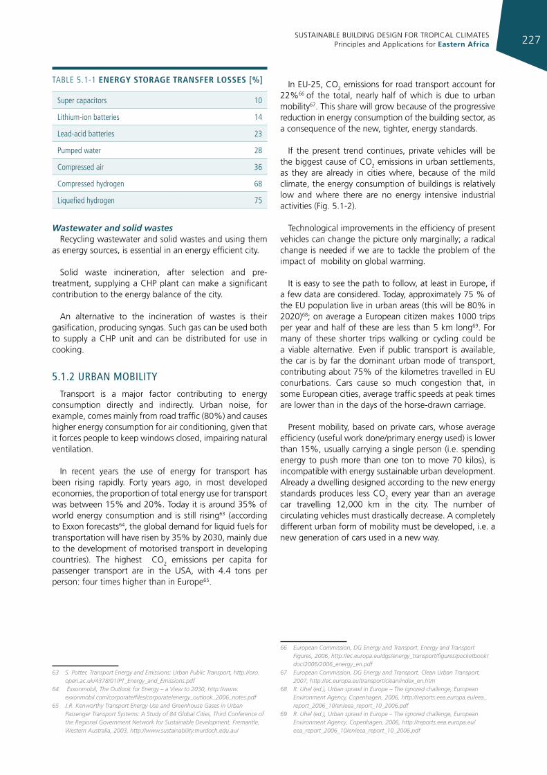
SUSTAINABLE BUILDING DESIGN FOR TROPICAL CLIMATES Principles and Applications for Eastern Africa 227
TABLe 5.1-1 energy storage transfer losses [%]
Super capacitors 10
Lithium-ion batteries 14
Lead-acid batteries 23
Pumped water 28
Compressed air 36
Compressed hydrogen 68
Liquefied hydrogen 75
Wastewater and solid wastesRecycling wastewater and solid wastes and using them
as energy sources, is essential in an energy efficient city.
Solid waste incineration, after selection and pre-treatment, supplying a CHP plant can make a significant contribution to the energy balance of the city.
An alternative to the incineration of wastes is their gasification, producing syngas. Such gas can be used both to supply a CHP unit and can be distributed for use in cooking.
5.1.2 urban mobIlITy
Transport is a major factor contributing to energy consumption directly and indirectly. Urban noise, for example, comes mainly from road traffic (80%) and causes higher energy consumption for air conditioning, given that it forces people to keep windows closed, impairing natural ventilation.
In recent years the use of energy for transport has been rising rapidly. Forty years ago, in most developed economies, the proportion of total energy use for transport was between 15% and 20%. Today it is around 35% of world energy consumption and is still rising63 (according to Exxon forecasts64, the global demand for liquid fuels for transportation will have risen by 35% by 2030, mainly due to the development of motorised transport in developing countries). The highest CO2 emissions per capita for passenger transport are in the USA, with 4.4 tons per person: four times higher than in Europe65.
63 S. Potter, Transport Energy and Emissions: Urban Public Transport, http://oro.open.ac.uk/4378/01/PT_Energy_and_Emissions.pdf
64 Exxonmobil, The Outlook for Energy – a View to 2030, http://www.exxonmobil.com/corporate/files/corporate/energy_outlook_2006_notes.pdf
65 J.R. Kenworthy Transport Energy Use and Greenhouse Gases in Urban Passenger Transport Systems: A Study of 84 Global Cities, Third Conference of the Regional Government Network for Sustainable Development, Fremantle, Western Australia, 2003, http://www.sustainability.murdoch.edu.au/
In EU-25, CO2 emissions for road transport account for 22%66 of the total, nearly half of which is due to urban mobility67. This share will grow because of the progressive reduction in energy consumption of the building sector, as a consequence of the new, tighter, energy standards.
If the present trend continues, private vehicles will be the biggest cause of CO2 emissions in urban settlements, as they are already in cities where, because of the mild climate, the energy consumption of buildings is relatively low and where there are no energy intensive industrial activities (Fig. 5.1-2).
Technological improvements in the efficiency of present vehicles can change the picture only marginally; a radical change is needed if we are to tackle the problem of the impact of mobility on global warming.
It is easy to see the path to follow, at least in Europe, if a few data are considered. Today, approximately 75 % of the EU population live in urban areas (this will be 80% in 2020)68; on average a European citizen makes 1000 trips per year and half of these are less than 5 km long69. For many of these shorter trips walking or cycling could be a viable alternative. Even if public transport is available, the car is by far the dominant urban mode of transport, contributing about 75% of the kilometres travelled in EU conurbations. Cars cause so much congestion that, in some European cities, average traffic speeds at peak times are lower than in the days of the horse-drawn carriage.
Present mobility, based on private cars, whose average efficiency (useful work done/primary energy used) is lower than 15%, usually carrying a single person (i.e. spending energy to push more than one ton to move 70 kilos), is incompatible with energy sustainable urban development. Already a dwelling designed according to the new energy standards produces less CO2 every year than an average car travelling 12,000 km in the city. The number of circulating vehicles must drastically decrease. A completely different urban form of mobility must be developed, i.e. a new generation of cars used in a new way.
66 European Commission, DG Energy and Transport, Energy and Transport Figures, 2006, http://ec.europa.eu/dgs/energy_transport/figures/pocketbook/doc/2006/2006_energy_en.pdf
67 European Commission, DG Energy and Transport, Clean Urban Transport, 2007, http://ec.europa.eu/transport/clean/index_en.htm
68 R. Uhel (ed.), Urban sprawl in Europe – The ignored challenge, European Environment Agency, Copenhagen, 2006, http://reports.eea.europa.eu/eea_report_2006_10/en/eea_report_10_2006.pdf
69 R. Uhel (ed.), Urban sprawl in Europe – The ignored challenge, European Environment Agency, Copenhagen, 2006, http://reports.eea.europa.eu/eea_report_2006_10/en/eea_report_10_2006.pdf
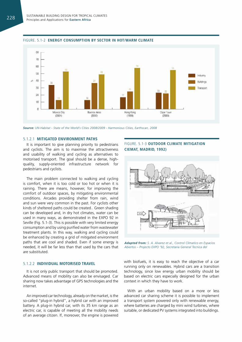
SUSTAINABLE BUILDING DESIGN FOR TROPICAL CLIMATES Principles and Applications for Eastern Africa228
5.1.2.1 mItIgated envIronment pathsIt is important to give planning priority to pedestrians
and cyclists. The aim is to maximise the attractiveness and usability of walking and cycling as alternatives to motorised transport. The goal should be a dense, high-quality, supply-oriented infrastructure network for pedestrians and cyclists.
The main problem connected to walking and cycling is comfort, when it is too cold or too hot or when it is raining. There are means, however, for improving the comfort of outdoor spaces, by mitigating environmental conditions. Arcades providing shelter from rain, wind and sun were very common in the past. For cyclists other kinds of sheltered paths could be created.. Green shading can be developed and, in dry hot climates, water can be used in many ways, as demonstrated in the EXPO 92 in Seville (Fig. 5.1-3). This is possible with very limited energy consumption and by using purified water from wastewater treatment plants. In this way, walking and cycling could be enhanced by creating a grid of mitigated environment paths that are cool and shaded. Even if some energy is needed, it will be far less than that used by the cars that are substituted.
5.1.2.2 IndIvIdual motorIsed travel
It is not only public transport that should be promoted. Advanced means of mobility can also be envisaged. Car sharing now takes advantage of GPS technologies and the internet.
An improved car technology, already on the market, is the so-called “plug-in hybrid”, a hybrid car with an improved battery. A plug-in hybrid car, with its 35 km range as an electric car, is capable of meeting all the mobility needs of an average citizen. If, moreover, the engine is powered
with biofuels, it is easy to reach the objective of a car running only on renewables. Hybrid cars are a transition technology, since low energy urban mobility should be based on electric cars especially designed for the urban context in which they have to work.
With an urban mobility based on a more or less advanced car sharing scheme it is possible to implement a transport system powered only with renewable energy, where batteries are charged by mini wind turbines, where suitable, or dedicated PV systems integrated into buildings.
Figure. 5.1-2 energy consumptIon by sector In hot/Warm clImate
Source: UN-Habitat - State of the World’s Cities 2008/2009 - Harmonious Cities, Earthscan, 2008
Figure. 5.1-3 outdoor clImate mItIgatIon cIemat, madrId, 1992)
Adapted from: S. A. Alvarez et al., Control Climatico en Espacios Abiertos – Projecto EXPO ’92, Secretaria General Tecnica del
SUSTAINABLE BUILDING DESIGN FOR TROPICAL CLIMATES Principles and Applications for Eastern Africa 229
5.1.3 urban gardens
Cities rarely produce food, and their supply of agricultural products normally comes from the rural hinterland and from the international market. This implies much energy use for transportation, as well as for cooling and storing of food. Moreover, much of this energy is wasted because of the production losses and food waste.
With the increase in urban population, more food will need to be produced and supplied from the hinterland. A seven- fold increase in food production will be needed to feed the projected population of 9 billion in 2050; this will demand higher usage of energy and land resources in an era where the existing usage already has adverse impacts on the environment and agricultural land is continuously lost through urban sprawl70.
Urban authorities can act against the reduction of agricultural land by controlling urban density and actively pursuing the reduction of food waste at the consumer and retailer end with policy measures such as awareness campaigns and charges for food waste. Promoting urban agriculture has proved to be another successful tool in addressing food shortages.
70 UN-Habitat, Sustainable Urban Energy: a sourcebook for Asia, 2012 - http://www.unhabitat.org/downloads/docs/11115_1_594431.pdf
5.2 waTer and sanITaTIon
Water is essential for the environment, food security and sustainable development. All the known civilizations flourished as long as their water sources also flourished and this is true in the present context too. Availability of drinking water and provision of sanitation facilities are the basic minimum requirements for healthy living. Water supply and sanitation, the two most important urban services, have wide ranging impacts on human health, quality of life, environment and productivity.
Water and energy are related. Water is used in the production of energy and energy is used to pump, treat and distribute water. As the population grows, so does the demand for water, and more and more energy is required.
The reliability and regularity of the water supply in low-income countries is a big problem, with poor quality water and a high price when bought from street vendors; on the sanitation front, shared toilets and pit latrines are inadequate and poorly maintained in urban areas71.
Despite technological advances, the global scenario still remains grim, as not all the inhabitants of the world have access to safe water and adequate sanitation.
71 UN-Habitat, Sustainable Urban Energy: A Sourcebook for Asia, 2012 - http://www.unhabitat.org/downloads/docs/11115_1_594431.pdf
Before the Soviet collapse, Cuba imported most of its needs. it exported sugar and tobacco to the Soviet union at agreed premium prices, and received oil in return, some of which was re-exported. This set-up created distorting incentives for large swathes of land to be given over to export crops grown in industrial monocultures, heavily dependent on oil-based inputs. Just before the collapse, in 1989, three times more land was dedicated to sugar than to growing food.
Then oil imports dropped by over half, crippling the economy and slashing foreign-exchange earnings from the re-export trade. The use of chemical pesticides and fertilisers dropped by 80 per cent, sounding a death knell to industrialised farming. The knock-on effect on people’s daily lives was dramatic. The availability of basic food staples, such as wheat and other grains, fell by half. The average Cuban’s calorie intake fell by over one-third in around five years, leading to an average weight loss of 20 pounds per person.
But in contrast to the situation that many countries find themselves in today, Cuba was in a position to respond. Serious and long-term investment in science, engineering, health and education meant the country had developed human resources, a strong social fabric and the capacity to act. Before the ‘oil shock’, Cuba was already investigating
forms of ecological farming far less dependent on fossil fuels. When the shock came, a system of regional research institutes, training centres and extension services was quickly put in place to support farmers.
Drawing on these strengths, the threat of serious food shortages was overcome within five years. At the heart of the transition after 1990 was a rapid shift to the use of biofertilisers and biopesticides, crop rotation and intercropping, and the use of animal labour and manure. in other words: a largely organic system. The success of small farms and of urban farms and gardens was also an important factor.
Shortages and rising food prices made urban farming into a very profitable activity. it also proved highly productive. Once the state backed the urban farming movement, it grew rapidly. Lots of backyards in Cuban cities became home to food crops and farm animals – grown and reared almost exclusively along organic lines. Half the food consumed in the capital, Havana, is grown in the city’s own gardens. urban gardens provide 60 per cent of the vegetables eaten in Cuba.
Source: The Green New Deal Group, A Green New Deal, new economic foundation, 2008 - http://dnwssx4l7gl7s.cloudfront.net/nefoundation/default/page/-/files/A_Green_New_Deal_1.pdf
SUSTAINABLE BUILDING DESIGN FOR TROPICAL CLIMATES Principles and Applications for Eastern Africa230
In most urban areas, the population is increasing rapidly and supplying adequate water to meet societal needs and ensuring equal access to water are the most urgent and significant challenges facing policy-makers.
As a consequence of rapid population growth, combined with industrialisation, urbanisation, intensification of agriculture and water intensive lifestyles a global water crisis has developed, exacerbated by climate change: water-related natural disasters, such as flooding, drought, and landslides, are more frequent and more severe; rising temperatures, causing increased evaporation and glacial melt, are reducing the reliability and quality of water supplies.
Problems related to falling water tables are widespread and cause serious damage, because they lead to both water shortages and, in coastal areas, to salt intrusion. Both contamination of drinking water and nitrate and heavy metal pollution of rivers, lakes and reservoirs are common problems throughout the world.
Water loss refers to the total amount of water lost through leakage in distribution networks. A conservative estimate for this has been placed at around 35 per cent of the total water supplied. For some low-income countries this loss may be as high as 80 per cent1.
This problem demands immediate attention and appropriate action to reduce avoidable stress on vital water resources. Numerous cities across the globe have already implemented programmes geared towards the step-by-step reduction of water loss and many water suppliers have developed effective strategies and applied technologies to control leakage and water loss.
5.2.1 waTer sources
Rainwater is a free source of nearly pure water and rainwater harvesting is the collection and storage of rainwater and other activities aimed at harvesting surface and ground water. It also includes prevention of losses through evaporation and seepage and all other hydrological and engineering interventions, aimed at conservation and efficient utilisation of the limited water endowment of physiographic unit such as a watershed. In general, water harvesting is the direct collection of rainwater. The rainwater collected can be stored for direct use or can be recharged into the ground water. Rain is the first form of water that we see in the hydrological cycle, hence is a primary source of water for us.
Rivers, lakes and ground water are all secondary sources of water. At the present time, we depend entirely on such secondary sources of water. In the process, generally, it is forgotten that rain is the ultimate source that feeds all these secondary sources. Water harvesting means making optimum use of rainwater at the place where it falls so as to attain self-sufficiency in water supply, without being dependent on remote water sources.
Groundwater refers to the water available underground in aquifers, and accessed by wells or boreholes.
5.2.2 ImporTance of waTer conservaTIon
Increased demand and the depletion of resources make water conservation an essential part of an efficient water management system, along with strategies for efficient reuse of water.
To that end the following three issues have to be considered: rainwater harvesting, water recycling and water conservation. For example rainwater can be stored in the earth or in cisterns for domestic use; grey and black water treated on-site can be reused; technologies for conserving water used for irrigation and domestic use can be implemented. Water efficiency measures also include reduction in losses and in overall water use.
The recommended measures for water reuse and water conservation can be summarized as follows:
• reduce the amount of potable water used for non-potable applications;
• install dual plumbing lines for the use of treated waste water for flushing applications. The treated water, which should meet the local pollution control board standards, can also be used for lawn watering;
• harvest rainwater;
• use rainwater harvested from the roof or from the site for irrigation, to whatever extent possible.
Recycling of water is another important aspect of water conservation. One way of recycling is by using aquatic plants. Raw sewage is recycled using aquatic plants (such as duckweed, water hyacinth, etc.) to produce clean water suitable for re-use in irrigation and industry.
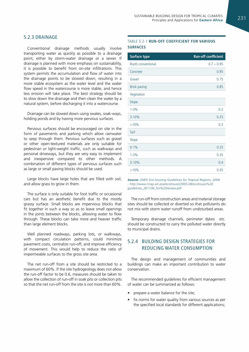
SUSTAINABLE BUILDING DESIGN FOR TROPICAL CLIMATES Principles and Applications for Eastern Africa 231
5.2.3 draInage
Conventional drainage methods usually involve transporting water as quickly as possible to a drainage point, either by storm-water drainage or a sewer. If drainage is planned with more emphasis on sustainability, it is possible to benefit from on-site infiltrations. This system permits the accumulation and flow of water into the drainage points to be slowed down, resulting in a more stable ecosystem as the water level and the water flow speed in the watercourse is more stable, and hence less erosion will take place. The best strategy should be to slow down the drainage and then clean the water by a natural system, before discharging it into a watercourse.
Drainage can be slowed down using swales, soak-ways, holding ponds and by having more pervious surfaces.
Pervious surfaces should be encouraged on site in the form of pavements and parking which allow rainwater to seep through them. Pervious surfaces such as gravel or other open-textured materials are only suitable for pedestrian or light-weight traffic, such as walkways and personal driveways, but they are very easy to implement and inexpensive compared to other methods. A combination of different types of pervious surfaces such as large or small paving blocks should be used.
Large blocks have large holes that are filled with soil, and allow grass to grow in them.
The surface is only suitable for foot traffic or occasional cars but has an aesthetic benefit due to the mostly grassy surface. Small blocks are impervious blocks that fit together in such a way so as to leave small openings in the joints between the blocks, allowing water to flow through. These blocks can take more and heavier traffic than large element blocks.
Well planned roadways, parking lots, or walkways, with compact circulation patterns, could minimize pavement costs, centralize run-off, and improve efficiency of movement. This would help to reduce the ratio of impermeable surfaces to the gross site area.
The net run-off from a site should be restricted to a maximum of 60%. If the site hydrogeology does not allow the run-off factor to be 0.6, measures should be taken to allow the collection of run-off in soak pits or collection pits so that the net run-off from the site is not more than 60%.
The run-off from construction areas and material storage sites should be collected or diverted so that pollutants do not mix with storm water runoff from undisturbed areas.
Temporary drainage channels, perimeter dykes etc. should be constructed to carry the polluted water directly to municipal drains.
5.2.4 buIldIng desIgn sTraTegIes for reducIng waTer consumpTIon
The design and management of communities and buildings can make an important contribution to water conservation.
The recommended guidelines for efficient management of water can be summarized as follows:
• prepare a water balance for the site;
• fix norms for water quality from various sources as per the specified local standards for different applications;
TABLe 5.2-1 run-off coeffIcIent for varIous surfaces
surface type run-off coefficient
roofs conventional 0.7 – 0.95
Concrete 0.95
gravel 0.75
Brick paving 0.85
Vegetation
Slope:
1-3% 0.2
3-10% 0.25
>10% 0.3
Turf
Slope:
0-1% 0.25
1-3% 0.35
3-10% 0.4
>10% 0.45
Source: UNEP, Eco-housing Guidelines for Tropical Regions, 2006 - http://www.rrcap.ait.asia/ecohouse/2005-08/ecohouse%20guidelines_261106_for%20review.pdf
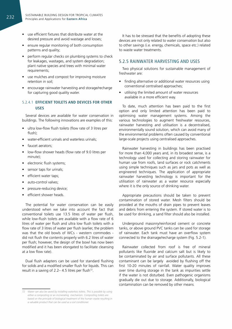
SUSTAINABLE BUILDING DESIGN FOR TROPICAL CLIMATES Principles and Applications for Eastern Africa232
• use efficient fixtures that distribute water at the desired pressure and avoid wastage and losses;
• ensure regular monitoring of both consumption patterns and quality;
• perform regular checks on plumbing systems to check for leakages, wastages, and system degradation; plant native species and trees with minimal water requirements;
• use mulches and compost for improving moisture retention in soil;
• encourage rainwater harvesting and storage/recharge for capturing good quality water.
5.2.4.1 effIcIent toIlets and devIces for other
uses
Several devices are available for water conservation in buildings. The following innovations are examples of this:
• ultra low-flow flush toilets (flow rate of 3 litres per flush);
• water-efficient urinals and waterless urinals;
• faucet aerators;
• low-flow shower heads (flow rate of 9.0 litres per minute);
• electronic flush systems;
• sensor taps for urinals;
• efficient water taps;
• auto-control valves;
• pressure-reducing device;
• efficient shower heads.
The potential for water conservation can be easily understood when we take into account the fact that conventional toilets use 13.5 litres of water per flush, while low-flush toilets are available with a flow rate of 6 litres of water per flush and ultra low flush toilets with a flow rate of 3 litres of water per flush (earlier, the problem was that the old bowls of WCs - western commodes - did not flush the contents properly with 6.2 litres of water per flush; however, the design of the bowl has now been modified and it has been elongated to facilitate cleansing at a low flow rate).
Dual flush adapters can be used for standard flushing for solids and a modified smaller flush for liquids. This can result in a saving of 2.2– 4.5 litres per flush72.
72 Water can also be saved by installing waterless toilets. This is possible by using either a composting or an incinerating mechanism. Composting toilets are based on the principle of biological treatment of the human waste resulting in a valuable product that can be used as a soil conditioner.
It has to be stressed that the benefits of adopting these devices are not only related to water conservation but also to other savings (i.e. energy, chemicals, space etc.) related to waste water treatments.
5.2.5 raInwaTer harvesTIng and uses
Two physical solutions for sustainable management of freshwater are:
• finding alternative or additional water resources using conventional centralised approaches;
• utilising the limited amount of water resources available in a more efficient way.
To date, much attention has been paid to the first option and only limited attention has been paid to optimising water management systems. Among the various technologies to augment freshwater resources, rainwater harvesting and utilisation is a decentralised, environmentally sound solution, which can avoid many of the environmental problems often caused by conventional large-scale projects using centralised approaches.
Rainwater harvesting in buildings has been practised for more than 4,000 years and, in its broadest sense, is a technology used for collecting and storing rainwater for human use from roofs, land surfaces or rock catchments using simple techniques such as jars and pots as well as engineered techniques. The application of appropriate rainwater harvesting technology is important for the utilisation of rainwater as a water resource especially where it is the only source of drinking water.
Appropriate precautions should be taken to prevent contamination of stored water. Mesh filters should be provided at the mouths of drain pipes to prevent leaves and debris from entering the system. If stored water is to be used for drinking, a sand filter should also be installed.
Underground masonry/reinforced cement or concrete tanks, or above ground PVC tanks can be used for storage of rainwater. Each tank must have an overflow system connected to the drainage/recharge system (Fig. 5.2-1).
Rainwater collected from roof is free of mineral pollutants like fluoride and calcium salt but is likely to be contaminated by air and surface pollutants. All these contaminant can be largely avoided by flushing off the first 10-20 minutes of rainfall. Water quality improves over time during storage in the tank as impurities settle if the water is not disturbed. Even pathogenic organisms gradually die out due to storage. Additionally, biological contamination can be removed by other means.
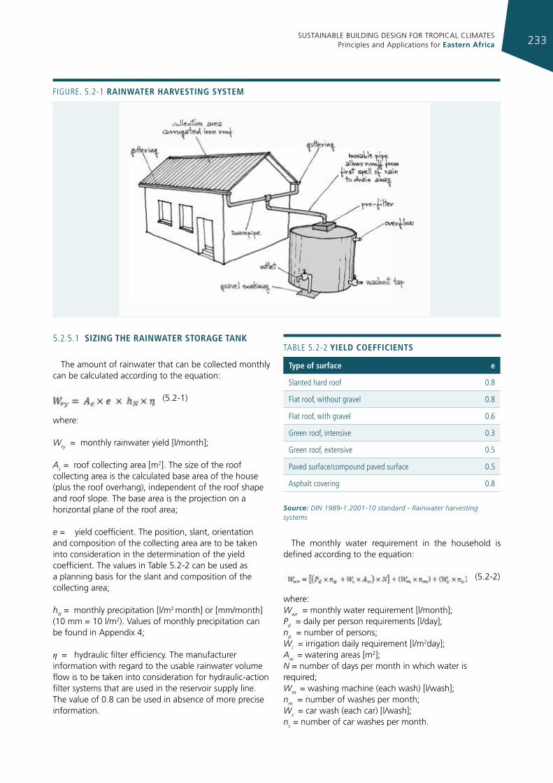
SUSTAINABLE BUILDING DESIGN FOR TROPICAL CLIMATES Principles and Applications for Eastern Africa 233
Figure. 5.2-1 raInWater harvestIng system
TABLe 5.2-2 yIeld coeffIcIents
type of surface e
Slanted hard roof 0.8
Flat roof, without gravel 0.8
Flat roof, with gravel 0.6
green roof, intensive 0.3
green roof, extensive 0.5
Paved surface/compound paved surface 0.5
Asphalt covering 0.8
Source: DIN 1989-1:2001-10 standard - Rainwater harvesting systems
5.2.5.1 sIzIng the raInWater storage tank
The amount of rainwater that can be collected monthly can be calculated according to the equation:
(5.2-1)
where:
Wry = monthly rainwater yield [l/month];
Ac = roof collecting area [m2]. The size of the roof collecting area is the calculated base area of the house (plus the roof overhang), independent of the roof shape and roof slope. The base area is the projection on a horizontal plane of the roof area;
e = yield coefficient. The position, slant, orientation and composition of the collecting area are to be taken into consideration in the determination of the yield coefficient. The values in Table 5.2-2 can be used as a planning basis for the slant and composition of the collecting area;
hN = monthly precipitation [l/m2 month] or [mm/month] (10 mm = 10 l/m2). Values of monthly precipitation can be found in Appendix 4;
η = hydraulic filter efficiency. The manufacturer information with regard to the usable rainwater volume flow is to be taken into consideration for hydraulic-action filter systems that are used in the reservoir supply line. The value of 0.8 can be used in absence of more precise information.
The monthly water requirement in the household is defined according to the equation:
(5.2-2)
where: Wwr = monthly water requirement [l/month]; Pd = daily per person requirements [l/day]; np = number of persons; Wi = irrigation daily requirement [l/m2day]; Aw = watering areas [m2]; N = number of days per month in which water is required; Wm = washing machine (each wash) [l/wash]; nm = number of washes per month; Wc = car wash (each car) [l/wash]; nc = number of car washes per month.
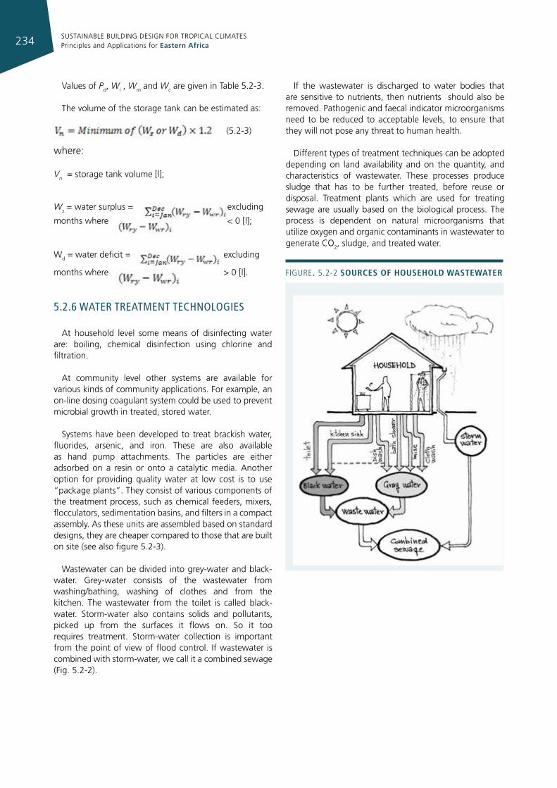
SUSTAINABLE BUILDING DESIGN FOR TROPICAL CLIMATES Principles and Applications for Eastern Africa234
Values of Pd, Wi , Wm and Wc are given in Table 5.2-3.
The volume of the storage tank can be estimated as:
(5.2-3)
where:
Vn = storage tank volume [l];
Ws = water surplus = excluding
months where < 0 [l];
Wd = water deficit = excluding
months where > 0 [l].
5.2.6 waTer TreaTmenT TechnologIes
At household level some means of disinfecting water are: boiling, chemical disinfection using chlorine and filtration.
At community level other systems are available for various kinds of community applications. For example, an on-line dosing coagulant system could be used to prevent microbial growth in treated, stored water.
Systems have been developed to treat brackish water, fluorides, arsenic, and iron. These are also available as hand pump attachments. The particles are either adsorbed on a resin or onto a catalytic media. Another option for providing quality water at low cost is to use “package plants”. They consist of various components of the treatment process, such as chemical feeders, mixers, flocculators, sedimentation basins, and filters in a compact assembly. As these units are assembled based on standard designs, they are cheaper compared to those that are built on site (see also figure 5.2-3).
Wastewater can be divided into grey-water and black-water. Grey-water consists of the wastewater from washing/bathing, washing of clothes and from the kitchen. The wastewater from the toilet is called black-water. Storm-water also contains solids and pollutants, picked up from the surfaces it flows on. So it too requires treatment. Storm-water collection is important from the point of view of flood control. If wastewater is combined with storm-water, we call it a combined sewage (Fig. 5.2-2).
If the wastewater is discharged to water bodies that are sensitive to nutrients, then nutrients should also be removed. Pathogenic and faecal indicator microorganisms need to be reduced to acceptable levels, to ensure that they will not pose any threat to human health.
Different types of treatment techniques can be adopted depending on land availability and on the quantity, and characteristics of wastewater. These processes produce sludge that has to be further treated, before reuse or disposal. Treatment plants which are used for treating sewage are usually based on the biological process. The process is dependent on natural microorganisms that utilize oxygen and organic contaminants in wastewater to generate CO
2, sludge, and treated water.
Figure. 5.2-2 sources of household WasteWater
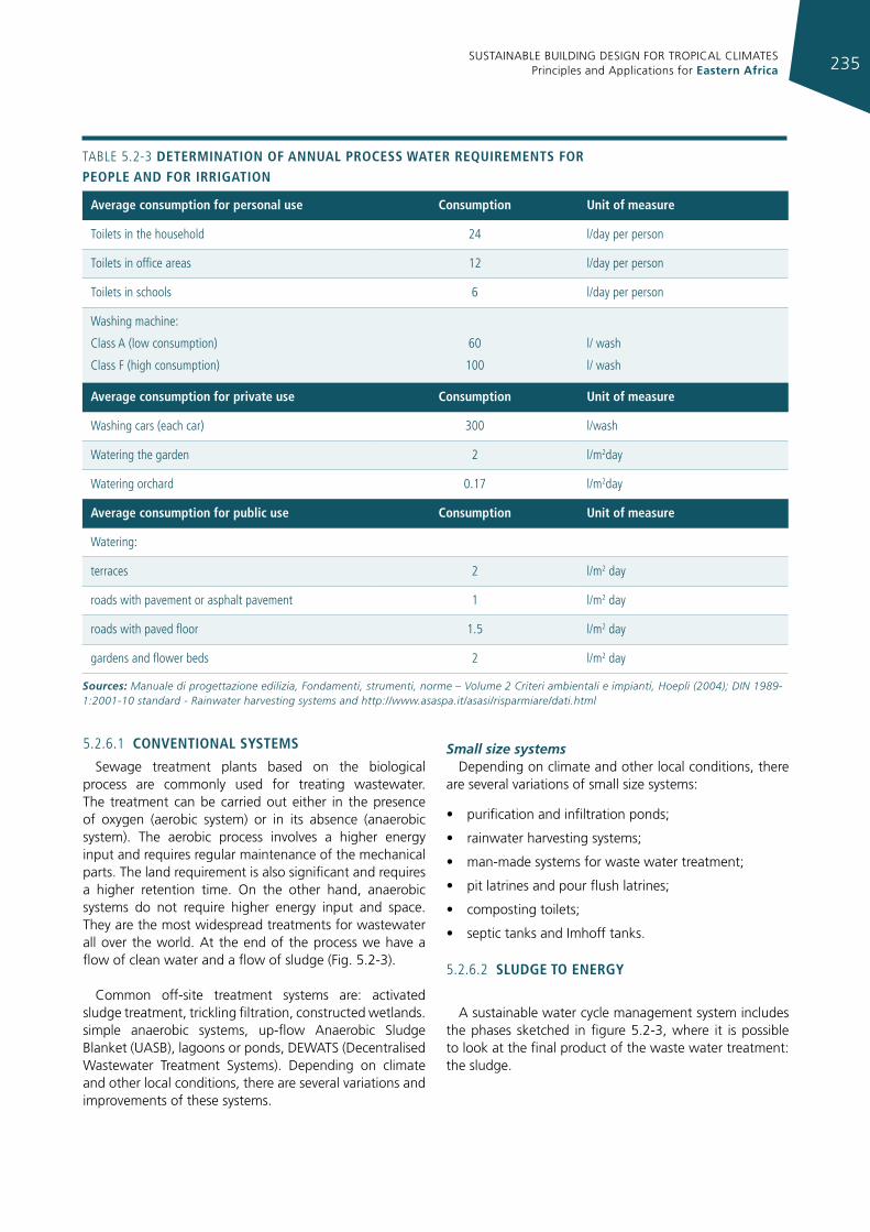
SUSTAINABLE BUILDING DESIGN FOR TROPICAL CLIMATES Principles and Applications for Eastern Africa 235
5.2.6.1 conventIonal systems
Sewage treatment plants based on the biological process are commonly used for treating wastewater. The treatment can be carried out either in the presence of oxygen (aerobic system) or in its absence (anaerobic system). The aerobic process involves a higher energy input and requires regular maintenance of the mechanical parts. The land requirement is also significant and requires a higher retention time. On the other hand, anaerobic systems do not require higher energy input and space. They are the most widespread treatments for wastewater all over the world. At the end of the process we have a flow of clean water and a flow of sludge (Fig. 5.2-3).
Common off-site treatment systems are: activated sludge treatment, trickling filtration, constructed wetlands. simple anaerobic systems, up-flow Anaerobic Sludge Blanket (UASB), lagoons or ponds, DEWATS (Decentralised Wastewater Treatment Systems). Depending on climate and other local conditions, there are several variations and improvements of these systems.
Small size systemsDepending on climate and other local conditions, there
are several variations of small size systems:
• purification and infiltration ponds;
• rainwater harvesting systems;
• man-made systems for waste water treatment;
• pit latrines and pour flush latrines;
• composting toilets;
• septic tanks and Imhoff tanks.
5.2.6.2 sludge to energy
A sustainable water cycle management system includes the phases sketched in figure 5.2-3, where it is possible to look at the final product of the waste water treatment: the sludge.
average consumption for personal use consumption unit of measure
Toilets in the household 24 l/day per person
Toilets in office areas 12 l/day per person
Toilets in schools 6 l/day per person
Washing machine:
Class A (low consumption)
Class F (high consumption)
60
100
l/ wash
l/ wash
average consumption for private use consumption unit of measure
Washing cars (each car) 300 l/wash
Watering the garden 2 l/m2day
Watering orchard 0.17 l/m2day
average consumption for public use consumption unit of measure
Watering:
terraces 2 l/m2 day
roads with pavement or asphalt pavement 1 l/m2 day
roads with paved floor 1.5 l/m2 day
gardens and flower beds 2 l/m2 day
Sources: Manuale di progettazione edilizia, Fondamenti, strumenti, norme – Volume 2 Criteri ambientali e impianti, Hoepli (2004); DIN 1989-1:2001-10 standard - Rainwater harvesting systems and http://www.asaspa.it/asasi/risparmiare/dati.html
TABLe 5.2-3 determInatIon of annual process Water requIrements for people and for IrrIgatIon
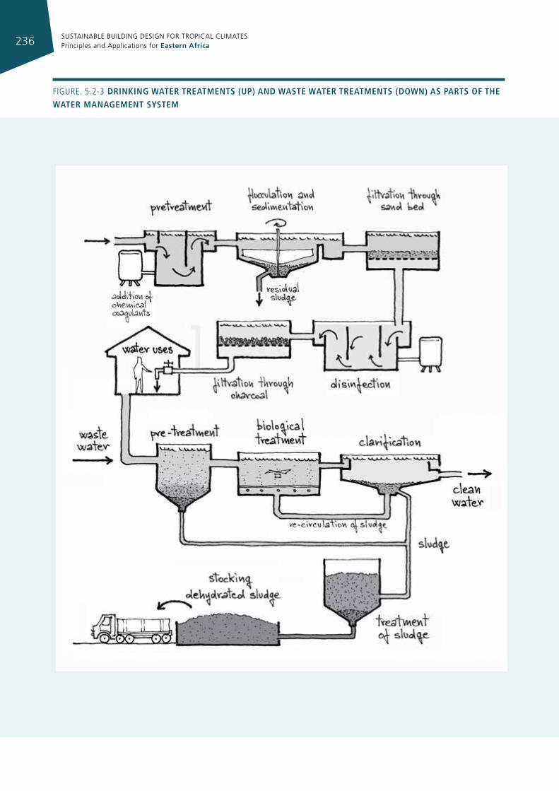
SUSTAINABLE BUILDING DESIGN FOR TROPICAL CLIMATES Principles and Applications for Eastern Africa236
Figure. 5.2-3 drInkIng Water treatments (up) and Waste Water treatments (doWn) as parts of the Water management system
SUSTAINABLE BUILDING DESIGN FOR TROPICAL CLIMATES Principles and Applications for Eastern Africa 237
Figure. 5.2-4 bIogas productIon from seWage Water at neIghbourhood level
Before the final disposal, sludge has to be treated. Also in this case, treatments can be bio-chemical or thermal and the most common are anaerobic digestion and gasification.
Biogas production is very promising because it could represent a very important energy source for the future and there are examples that demonstrate that it could also be used for cooking and transportation.
Application of biogas technology in urban settlements may be on-site (household level, see section 6.4) or off-site (neighbourhood level), figure 5.2-4.
The factors to consider in providing and siting of a biogas system at neighbourhood level are:
• availability of land for the construction of a plant and reuse of the effluents;
• urbanization patterns and population density;
• adaptability of existing sewerage systems (separate from incompatible industrial waste);
• socio–cultural and socio-economic constraints, and opportunities for community participation in construction, operation, maintenance and access to benefits;
• financial analysis.
When biogas is upgraded, bio-methane can be obtained. The possible uses of bio-methane into a network are equivalent to those of natural gas and can be summarized as follows:
• domestic hot water, cooking, heat production;
• cogeneration and micro-cogeneration plants, industrial use;
• fuel for motor vehicles.
5.2.7 waTer cycle: maIn crITIcIsms and soluTIons
In many cities sewerage systems are not available or are not managed correctly. A century ago the same was true in a large number of cities in today’s developed countries.
At that time, even when a sewerage system was available, wastewater was discharged directly into rivers, lakes or the sea. Later, slowly, water treatment started to be implemented, but with the open cycle approach: no energy was recovered with biogas plants and no treated water was reused. It is still like this in cities in most developed countries.
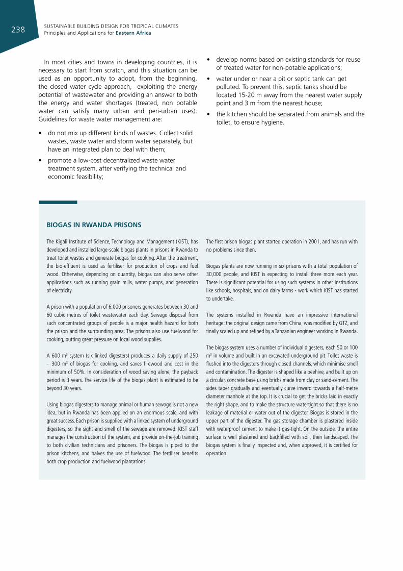
SUSTAINABLE BUILDING DESIGN FOR TROPICAL CLIMATES Principles and Applications for Eastern Africa238
In most cities and towns in developing countries, it is necessary to start from scratch, and this situation can be used as an opportunity to adopt, from the beginning, the closed water cycle approach, exploiting the energy potential of wastewater and providing an answer to both the energy and water shortages (treated, non potable water can satisfy many urban and peri-urban uses).Guidelines for waste water management are:
• do not mix up different kinds of wastes. Collect solid wastes, waste water and storm water separately, but have an integrated plan to deal with them;
• promote a low-cost decentralized waste water treatment system, after verifying the technical and economic feasibility;
• develop norms based on existing standards for reuse of treated water for non-potable applications;
• water under or near a pit or septic tank can get polluted. To prevent this, septic tanks should be located 15-20 m away from the nearest water supply point and 3 m from the nearest house;
• the kitchen should be separated from animals and the toilet, to ensure hygiene.
bIogAS In RwAnDA pRISonS
The Kigali institute of Science, Technology and Management (KiST), has developed and installed large-scale biogas plants in prisons in rwanda to treat toilet wastes and generate biogas for cooking. After the treatment, the bio-effluent is used as fertiliser for production of crops and fuel wood. Otherwise, depending on quantity, biogas can also serve other applications such as running grain mills, water pumps, and generation of electricity.
A prison with a population of 6,000 prisoners generates between 30 and 60 cubic metres of toilet wastewater each day. Sewage disposal from such concentrated groups of people is a major health hazard for both the prison and the surrounding area. The prisons also use fuelwood for cooking, putting great pressure on local wood supplies.
A 600 m3 system (six linked digesters) produces a daily supply of 250 – 300 m3 of biogas for cooking, and saves firewood and cost in the minimum of 50%. in consideration of wood saving alone, the payback period is 3 years. The service life of the biogas plant is estimated to be beyond 30 years.
using biogas digesters to manage animal or human sewage is not a new idea, but in rwanda has been applied on an enormous scale, and with great success. each prison is supplied with a linked system of underground digesters, so the sight and smell of the sewage are removed. KiST staff manages the construction of the system, and provide on-the-job training to both civilian technicians and prisoners. The biogas is piped to the prison kitchens, and halves the use of fuelwood. The fertiliser benefits both crop production and fuelwood plantations.
The first prison biogas plant started operation in 2001, and has run with no problems since then.
Biogas plants are now running in six prisons with a total population of 30,000 people, and KiST is expecting to install three more each year. There is significant potential for using such systems in other institutions like schools, hospitals, and on dairy farms - work which KiST has started to undertake.
The systems installed in rwanda have an impressive international heritage: the original design came from China, was modified by gTZ, and finally scaled up and refined by a Tanzanian engineer working in rwanda.
The biogas system uses a number of individual digesters, each 50 or 100 m3 in volume and built in an excavated underground pit. Toilet waste is flushed into the digesters through closed channels, which minimise smell and contamination. The digester is shaped like a beehive, and built up on a circular, concrete base using bricks made from clay or sand-cement. The sides taper gradually and eventually curve inward towards a half-metre diameter manhole at the top. it is crucial to get the bricks laid in exactly the right shape, and to make the structure watertight so that there is no leakage of material or water out of the digester. Biogas is stored in the upper part of the digester. The gas storage chamber is plastered inside with waterproof cement to make it gas-tight. On the outside, the entire surface is well plastered and backfilled with soil, then landscaped. The biogas system is finally inspected and, when approved, it is certified for operation.
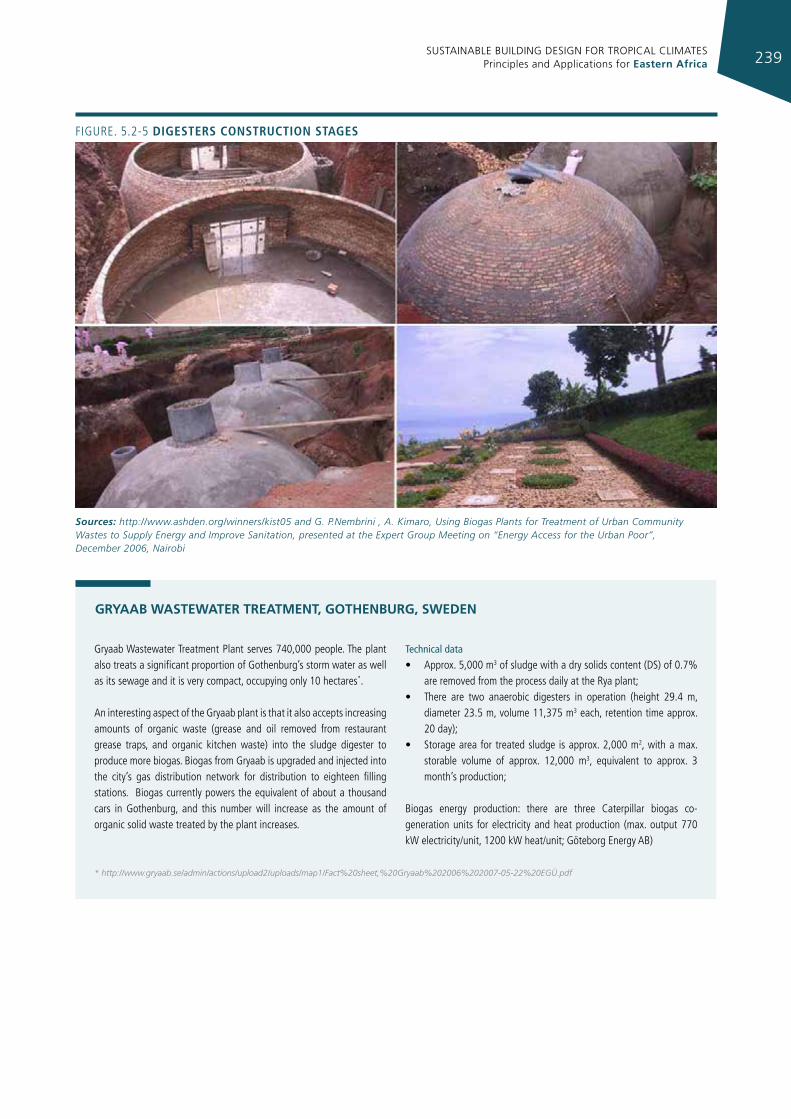
SUSTAINABLE BUILDING DESIGN FOR TROPICAL CLIMATES Principles and Applications for Eastern Africa 239
gryaab Wastewater Treatment Plant serves 740,000 people. The plant also treats a significant proportion of gothenburg’s storm water as well as its sewage and it is very compact, occupying only 10 hectares*.
An interesting aspect of the gryaab plant is that it also accepts increasing amounts of organic waste (grease and oil removed from restaurant grease traps, and organic kitchen waste) into the sludge digester to produce more biogas. Biogas from gryaab is upgraded and injected into the city’s gas distribution network for distribution to eighteen filling stations. Biogas currently powers the equivalent of about a thousand cars in gothenburg, and this number will increase as the amount of organic solid waste treated by the plant increases.
Technical data
• Approx. 5,000 m3 of sludge with a dry solids content (DS) of 0.7% are removed from the process daily at the rya plant;
• There are two anaerobic digesters in operation (height 29.4 m, diameter 23.5 m, volume 11,375 m3 each, retention time approx. 20 day);
• Storage area for treated sludge is approx. 2,000 m2, with a max. storable volume of approx. 12,000 m3, equivalent to approx. 3 month’s production;
Biogas energy production: there are three Caterpillar biogas co-generation units for electricity and heat production (max. output 770 kW electricity/unit, 1200 kW heat/unit; göteborg energy AB)
gRYAAb wAStEwAtER tREAtMEnt, gotHEnbuRg, SwEDEn
* http://www.gryaab.se/admin/actions/upload2/uploads/map1/Fact%20sheet,%20Gryaab%202006%202007-05-22%20EGÜ.pdf
Figure. 5.2-5 dIgesters constructIon stages
Sources: http://www.ashden.org/winners/kist05 and G. P.Nembrini , A. Kimaro, Using Biogas Plants for Treatment of Urban Community Wastes to Supply Energy and Improve Sanitation, presented at the Expert Group Meeting on “Energy Access for the Urban Poor”, December 2006, Nairobi
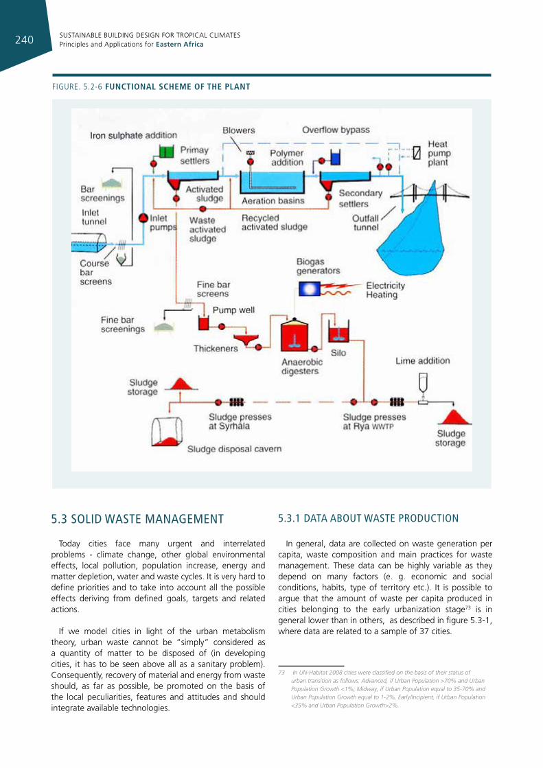
SUSTAINABLE BUILDING DESIGN FOR TROPICAL CLIMATES Principles and Applications for Eastern Africa240
Figure. 5.2-6 functIonal scheme of the plant
5.3 solId wasTe managemenT
Today cities face many urgent and interrelated problems - climate change, other global environmental effects, local pollution, population increase, energy and matter depletion, water and waste cycles. It is very hard to define priorities and to take into account all the possible effects deriving from defined goals, targets and related actions.
If we model cities in light of the urban metabolism theory, urban waste cannot be “simply” considered as a quantity of matter to be disposed of (in developing cities, it has to be seen above all as a sanitary problem). Consequently, recovery of material and energy from waste should, as far as possible, be promoted on the basis of the local peculiarities, features and attitudes and should integrate available technologies.
5.3.1 daTa abouT wasTe producTIon
In general, data are collected on waste generation per capita, waste composition and main practices for waste management. These data can be highly variable as they depend on many factors (e. g. economic and social conditions, habits, type of territory etc.). It is possible to argue that the amount of waste per capita produced in cities belonging to the early urbanization stage73 is in general lower than in others, as described in figure 5.3-1, where data are related to a sample of 37 cities.
73 In UN-Habitat 2008 cities were classified on the basis of their status of urban transition as follows: Advanced, if Urban Population >70% and Urban Population Growth <1%; Midway, if Urban Population equal to 35-70% and Urban Population Growth equal to 1-2%, Early/Incipient, if Urban Population <35% and Urban Population Growth>2%.
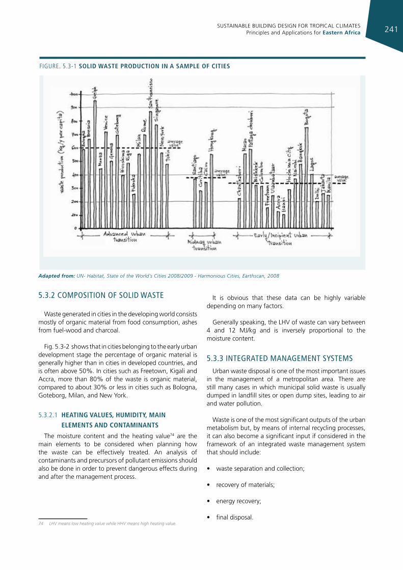
SUSTAINABLE BUILDING DESIGN FOR TROPICAL CLIMATES Principles and Applications for Eastern Africa 241
5.3.2 composITIon of solId wasTe
Waste generated in cities in the developing world consists mostly of organic material from food consumption, ashes from fuel-wood and charcoal.
Fig. 5.3-2 shows that in cities belonging to the early urban development stage the percentage of organic material is generally higher than in cities in developed countries, and is often above 50%. In cities such as Freetown, Kigali and Accra, more than 80% of the waste is organic material, compared to about 30% or less in cities such as Bologna, Goteborg, Milan, and New York.
5.3.2.1 heatIng values, humIdIty, maIn
elements and contamInants
The moisture content and the heating value74 are the main elements to be considered when planning how the waste can be effectively treated. An analysis of contaminants and precursors of pollutant emissions should also be done in order to prevent dangerous effects during and after the management process.
74 LHV means low heating value while HHV means high heating value.
It is obvious that these data can be highly variable depending on many factors.
Generally speaking, the LHV of waste can vary between 4 and 12 MJ/kg and is inversely proportional to the moisture content.
5.3.3 InTegraTed managemenT sysTems
Urban waste disposal is one of the most important issues in the management of a metropolitan area. There are still many cases in which municipal solid waste is usually dumped in landfill sites or open dump sites, leading to air and water pollution.
Waste is one of the most significant outputs of the urban metabolism but, by means of internal recycling processes, it can also become a significant input if considered in the framework of an integrated waste management system that should include:
• waste separation and collection;
• recovery of materials;
• energy recovery;
• final disposal.
Figure. 5.3-1 solId Waste productIon In a sample of cItIes
Adapted from: UN- Habitat, State of the World’s Cities 2008/2009 - Harmonious Cities, Earthscan, 2008
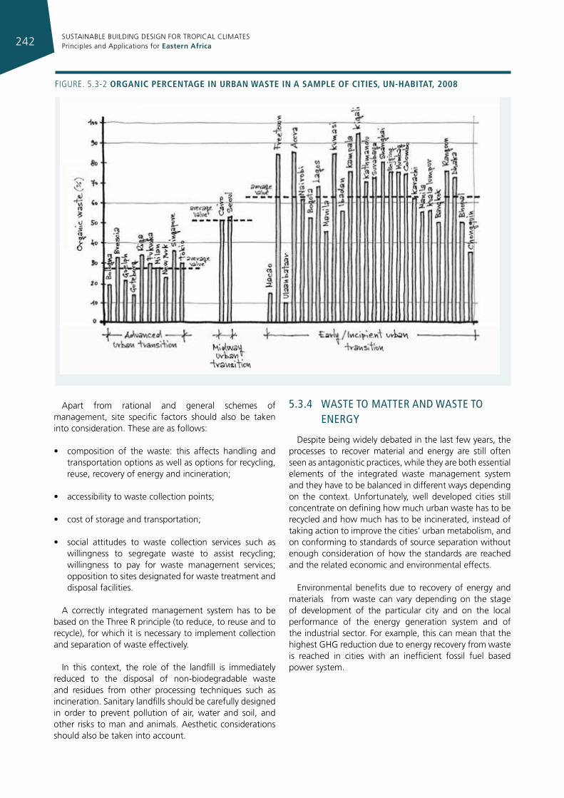
SUSTAINABLE BUILDING DESIGN FOR TROPICAL CLIMATES Principles and Applications for Eastern Africa242
Apart from rational and general schemes of management, site specific factors should also be taken into consideration. These are as follows:
• composition of the waste: this affects handling and transportation options as well as options for recycling, reuse, recovery of energy and incineration;
• accessibility to waste collection points;
• cost of storage and transportation;
• social attitudes to waste collection services such as willingness to segregate waste to assist recycling; willingness to pay for waste management services; opposition to sites designated for waste treatment and disposal facilities.
A correctly integrated management system has to be based on the Three R principle (to reduce, to reuse and to recycle), for which it is necessary to implement collection and separation of waste effectively.
In this context, the role of the landfill is immediately reduced to the disposal of non-biodegradable waste and residues from other processing techniques such as incineration. Sanitary landfills should be carefully designed in order to prevent pollution of air, water and soil, and other risks to man and animals. Aesthetic considerations should also be taken into account.
5.3.4 wasTe To maTTer and wasTe To energy
Despite being widely debated in the last few years, the processes to recover material and energy are still often seen as antagonistic practices, while they are both essential elements of the integrated waste management system and they have to be balanced in different ways depending on the context. Unfortunately, well developed cities still concentrate on defining how much urban waste has to be recycled and how much has to be incinerated, instead of taking action to improve the cities’ urban metabolism, and on conforming to standards of source separation without enough consideration of how the standards are reached and the related economic and environmental effects.
Environmental benefits due to recovery of energy and materials from waste can vary depending on the stage of development of the particular city and on the local performance of the energy generation system and of the industrial sector. For example, this can mean that the highest GHG reduction due to energy recovery from waste is reached in cities with an inefficient fossil fuel based power system.
Figure. 5.3-2 organIc percentage In urban Waste In a sample of cItIes, un-habItat, 2008
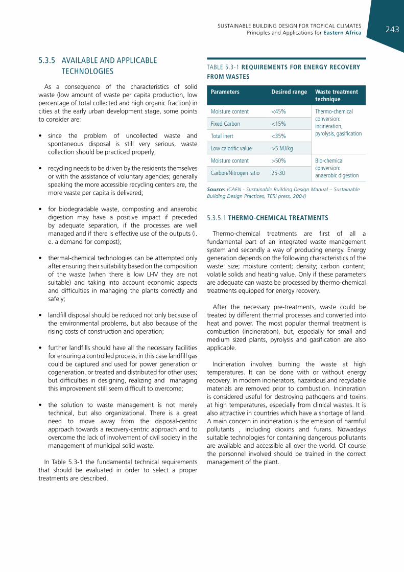
SUSTAINABLE BUILDING DESIGN FOR TROPICAL CLIMATES Principles and Applications for Eastern Africa 243
5.3.5 avaIlable and applIcable TechnologIes
As a consequence of the characteristics of solid waste (low amount of waste per capita production, low percentage of total collected and high organic fraction) in cities at the early urban development stage, some points to consider are:
• since the problem of uncollected waste and spontaneous disposal is still very serious, waste collection should be practiced properly;
• recycling needs to be driven by the residents themselves or with the assistance of voluntary agencies; generally speaking the more accessible recycling centers are, the more waste per capita is delivered;
• for biodegradable waste, composting and anaerobic digestion may have a positive impact if preceded by adequate separation, if the processes are well managed and if there is effective use of the outputs (i. e. a demand for compost);
• thermal-chemical technologies can be attempted only after ensuring their suitability based on the composition of the waste (when there is low LHV they are not suitable) and taking into account economic aspects and difficulties in managing the plants correctly and safely;
• landfill disposal should be reduced not only because of the environmental problems, but also because of the rising costs of construction and operation;
• further landfills should have all the necessary facilities for ensuring a controlled process; in this case landfill gas could be captured and used for power generation or cogeneration, or treated and distributed for other uses; but difficulties in designing, realizing and managing this improvement still seem difficult to overcome;
• the solution to waste management is not merely technical, but also organizational. There is a great need to move away from the disposal-centric approach towards a recovery-centric approach and to overcome the lack of involvement of civil society in the management of municipal solid waste.
In Table 5.3-1 the fundamental technical requirements that should be evaluated in order to select a proper treatments are described.
5.3.5.1 thermo-chemIcal treatments
Thermo-chemical treatments are first of all a fundamental part of an integrated waste management system and secondly a way of producing energy. Energy generation depends on the following characteristics of the waste: size; moisture content; density; carbon content; volatile solids and heating value. Only if these parameters are adequate can waste be processed by thermo-chemical treatments equipped for energy recovery.
After the necessary pre-treatments, waste could be treated by different thermal processes and converted into heat and power. The most popular thermal treatment is combustion (incineration), but, especially for small and medium sized plants, pyrolysis and gasification are also applicable.
Incineration involves burning the waste at high temperatures. It can be done with or without energy recovery. In modern incinerators, hazardous and recyclable materials are removed prior to combustion. Incineration is considered useful for destroying pathogens and toxins at high temperatures, especially from clinical wastes. It is also attractive in countries which have a shortage of land. A main concern in incineration is the emission of harmful pollutants , including dioxins and furans. Nowadays suitable technologies for containing dangerous pollutants are available and accessible all over the world. Of course the personnel involved should be trained in the correct management of the plant.
TABLe 5.3-1 requIrements for energy recovery from Wastes
parameters desired range Waste treatment technique
Moisture content <45% Thermo-chemical conversion: incineration, pyrolysis, gasification
Fixed Carbon <15%
Total inert <35%
Low calorific value >5 MJ/kg
Moisture content >50% Bio-chemical conversion: anaerobic digestion Carbon/Nitrogen ratio 25-30
Source: ICAEN - Sustainable Building Design Manual – Sustainable Building Design Practices, TERI press, 2004)
SUSTAINABLE BUILDING DESIGN FOR TROPICAL CLIMATES Principles and Applications for Eastern Africa244
Technologies for pyrolysis and gasification of urban wastes are also available at commercial scale in this field. Pyrolysis and gasification are technically and economically feasible if they are combined with the integrated waste management systems of small regions (20-80 kt/year). Compared with combustion, pyrolysis and gasification could bring benefits such as smaller space occupation, more acceptability, fewer additives, less (and more inert) slag, fuels available for storage, transportation and different uses (including gas turbine combined cycle or co-combustion). Despite the small number of commercial applications, the energy and mass balance of existing plants can deliver performances that are nearly comparable to those of combustion plants.
5.3.5.2 mechanIcal bIologIcal treatment (mbt)
These are a flexible mix of mechanical and biological treatment methods that are used to recover all types of resources from a mixed waste stream. The recovered materials can then be recycled. The mechanical part is similar to the MRF (Materials Recovery Facility75) and the biological treatment normally consists of anaerobic digestion or composting. The process may also produce a fuel from the waste, known as Refuse Derived Fuel (RDF).
5.3.5.3 bIo-chemIcal treatments: compostIng
and anaerobIc dIgestIon
Anaerobic digestion Biogas generation could have important effects in terms
of reduction of green house gases and use of renewable energies. Depending on the end use, different biogas treatments are necessary. For some applications, where it is important to have a high energy content in the gas, e. g. as vehicle fuel or for grid injection, the gas needs to be upgraded. Upgrading technologies have various advantages, most notably the production of an alternative source for methane (biomethane) which may help to reduce dependence on natural gas, which in the long run may result in a monetary profit.
CompostingWhen anaerobic digestion is not feasible, wet organic
waste can be treated by composting. This is an aerobic process, where bacteria act on the sludge to produce more stable organic material (humus), which is very good as a soil conditioner.
75 MRF is a specialized plant that receives, separates and prepares recyclable materials for marketing to end-user manufacturers
5.3.6 maIn crITIcIsms and soluTIons
According to technical literature it is possible to argue that urban waste is an underutilized source of materials and energy and, in developing cities, a dangerous source of pollutants and diseases.
Further, although waste management has an important role as a source of energy and materials and it creates new net employment, there can be many obstacles to the introduction of new urban policies: an ill-defined institutional framework, insufficient financial resources, uncertainty related to the available data, lack of skill and of specialists capable of putting policies into action , lack of information of the citizens, resistance to change. All these are obstacles that are difficult to predict.
5.3.7 basIc guIdelInes
Although waste management should be planned with solutions that are strictly dependent on the local situation, the following guidelines should be followed in order to overcome many of the previously mentioned problems:
• provide facilities for collection of segregated waste;
• identify facilities for the recycling of non-biodegradable wastes such as plastics, glass, and paper;
• develop norms for disposal of non-degradable and inert waste in landfills based on local standards, to ensure a safe environment in the surrounding areas. Sanitary landfills need to be carefully designed and people need to be trained in managing and maintaining them (a common mistake is to provide the infrastructure, but neglect the managerial aspects);
• establish an efficient waste reduction, recycling, and reuse (3R) programme;
• avoid or reduce toxic and hazardous materials. Recycle items such as ballasts, mercury-based lighting products, used oil, unusable batteries, etc.
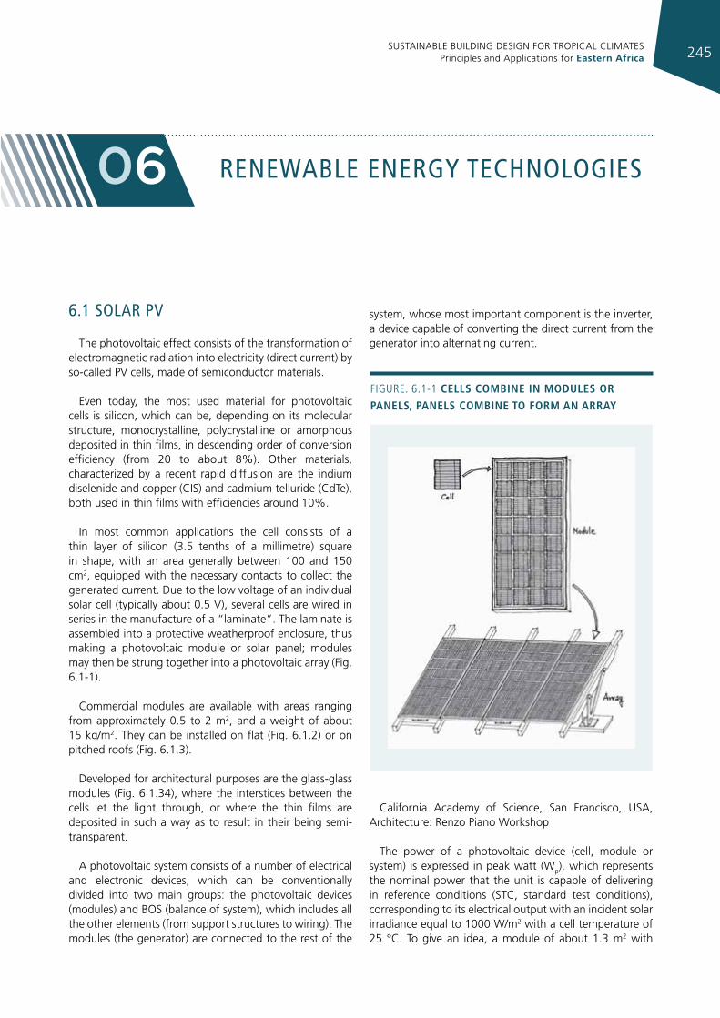
SUSTAINABLE BUILDING DESIGN FOR TROPICAL CLIMATES Principles and Applications for Eastern Africa 245
renewable energy TechnologIes06
6.1 solar pv
The photovoltaic effect consists of the transformation of electromagnetic radiation into electricity (direct current) by so-called PV cells, made of semiconductor materials.
Even today, the most used material for photovoltaic cells is silicon, which can be, depending on its molecular structure, monocrystalline, polycrystalline or amorphous deposited in thin films, in descending order of conversion efficiency (from 20 to about 8%). Other materials, characterized by a recent rapid diffusion are the indium diselenide and copper (CIS) and cadmium telluride (CdTe), both used in thin films with efficiencies around 10%.
In most common applications the cell consists of a thin layer of silicon (3.5 tenths of a millimetre) square in shape, with an area generally between 100 and 150 cm2, equipped with the necessary contacts to collect the generated current. Due to the low voltage of an individual solar cell (typically about 0.5 V), several cells are wired in series in the manufacture of a “laminate”. The laminate is assembled into a protective weatherproof enclosure, thus making a photovoltaic module or solar panel; modules may then be strung together into a photovoltaic array (Fig. 6.1-1).
Commercial modules are available with areas ranging from approximately 0.5 to 2 m2, and a weight of about 15 kg/m2. They can be installed on flat (Fig. 6.1.2) or on pitched roofs (Fig. 6.1.3).
Developed for architectural purposes are the glass-glass modules (Fig. 6.1.34), where the interstices between the cells let the light through, or where the thin films are deposited in such a way as to result in their being semi-transparent.
A photovoltaic system consists of a number of electrical and electronic devices, which can be conventionally divided into two main groups: the photovoltaic devices (modules) and BOS (balance of system), which includes all the other elements (from support structures to wiring). The modules (the generator) are connected to the rest of the
system, whose most important component is the inverter, a device capable of converting the direct current from the generator into alternating current.
California Academy of Science, San Francisco, USA, Architecture: Renzo Piano Workshop
The power of a photovoltaic device (cell, module or system) is expressed in peak watt (Wp), which represents the nominal power that the unit is capable of delivering in reference conditions (STC, standard test conditions), corresponding to its electrical output with an incident solar irradiance equal to 1000 W/m2 with a cell temperature of 25 °C. To give an idea, a module of about 1.3 m2 with
Figure. 6.1-1 cells combIne In modules or panels, panels combIne to form an array
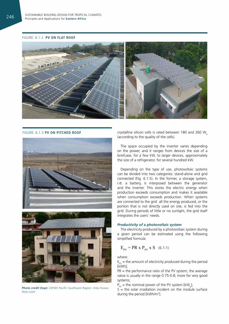
SUSTAINABLE BUILDING DESIGN FOR TROPICAL CLIMATES Principles and Applications for Eastern Africa246
crystalline silicon cells is rated between 180 and 260 Wp (according to the quality of the cells).
The space occupied by the inverter varies depending on the power, and it ranges from devices the size of a briefcase, for a few kW, to larger devices, approximately the size of a refrigerator, for several hundred kW.
Depending on the type of use, photovoltaic systems can be divided into two categories: stand-alone and grid connected (Fig. 6.1.5). In the former, a storage system, i.e. a battery, is interposed between the generator and the inverter. This stores the electric energy when production exceeds consumption and makes it available when consumption exceeds production. When systems are connected to the grid all the energy produced, or the portion that is not directly used on site, is fed into the grid. During periods of little or no sunlight, the grid itself integrates the users’ needs.
Productivity of a photovoltaic systemThe electricity produced by a photovoltaic system during
a given period can be estimated using the following simplified formula:
EPV = PR x PPV x S (6.1-1)
where:EPV = the amount of electricity produced during the period [kWh];PR = the performance ratio of the PV system; the average value is usually in the range 0.75-0.8; more for very good systems;PPV = the nominal power of the PV system [kWp];S = the solar irradiation incident on the module surface during the period [kWh/m2].
Figure. 6.1-2 pv on flat roof
Figure. 6.1-3 pv on pItched roof
Photo credit (top): USFWS Pacific Southwest Region -http://www.flickr.com/
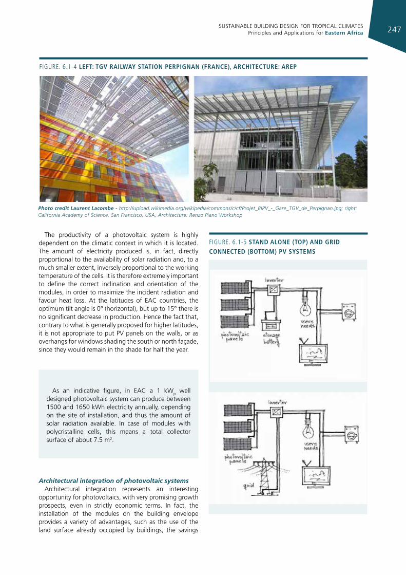
SUSTAINABLE BUILDING DESIGN FOR TROPICAL CLIMATES Principles and Applications for Eastern Africa 247
Figure. 6.1-4 left: tgv raIlWay statIon perpIgnan (france), archItecture: arep
Photo credit Laurent Lacombe - http://upload.wikimedia.org/wikipedia/commons/c/cf/Projet_BIPV_-_Gare_TGV_de_Perpignan.jpg; right: California Academy of Science, San Francisco, USA, Architecture: Renzo Piano Workshop
The productivity of a photovoltaic system is highly dependent on the climatic context in which it is located. The amount of electricity produced is, in fact, directly proportional to the availability of solar radiation and, to a much smaller extent, inversely proportional to the working temperature of the cells. It is therefore extremely important to define the correct inclination and orientation of the modules, in order to maximize the incident radiation and favour heat loss. At the latitudes of EAC countries, the optimum tilt angle is 0° (horizontal), but up to 15° there is no significant decrease in production. Hence the fact that, contrary to what is generally proposed for higher latitudes, it is not appropriate to put PV panels on the walls, or as overhangs for windows shading the south or north façade, since they would remain in the shade for half the year.
Architectural integration of photovoltaic systemsArchitectural integration represents an interesting
opportunity for photovoltaics, with very promising growth prospects, even in strictly economic terms. In fact, the installation of the modules on the building envelope provides a variety of advantages, such as the use of the land surface already occupied by buildings, the savings
As an indicative figure, in EAC a 1 kWp well designed photovoltaic system can produce between 1500 and 1650 kWh electricity annually, depending on the site of installation, and thus the amount of solar radiation available. In case of modules with polycristalline cells, this means a total collector surface of about 7.5 m2.
Figure. 6.1-5 stand alone (top) and grId connected (bottom) pv systems
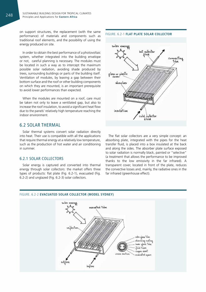
SUSTAINABLE BUILDING DESIGN FOR TROPICAL CLIMATES Principles and Applications for Eastern Africa248
on support structures, the replacement (with the same performance) of materials and components such as traditional roof elements, and the possibility of using the energy produced on site.
In order to obtain the best performance of a photovoltaic system, whether integrated into the building envelope or not, careful planning is necessary. The modules must be located in such a way as to intercept the maximum possible solar radiation, avoiding shade produced by trees, surrounding buildings or parts of the building itself. Ventilation of modules, by leaving a gap between their bottom surface and the roof or other building components on which they are mounted, is an important prerequisite to avoid lower performances than expected.
When the modules are mounted on a roof, care must be taken not only to leave a ventilated gap, but also to increase the roof insulation, to avoid a significant heat flow due to the panels’ relatively high temperature reaching the indoor environment.
6.2 solar ThermalSolar thermal systems convert solar radiation directly
into heat. Their use is compatible with all the applications that require thermal energy at a relatively low temperature, such as the production of hot water and air conditioning in summer.
6.2.1 solar collecTors
Solar energy is captured and converted into thermal energy through solar collectors: the market offers three types of products: flat plate (Fig. 6.2-1), evacuated (Fig. 6.2-2) and unglazed (Fig. 6.2-3) solar collectors.
The flat solar collectors are a very simple concept: an absorbing plate, integrated with the pipes for the heat transfer fluid, is placed into a box insulated at the back and along the sides. The absorber plate surface exposed to solar radiation is normally black, painted or “selective” (a treatment that allows the performance to be improved thanks to the low emissivity in the far infrared). A transparent cover, located in front of the plate, reduces the convective losses and, mainly, the radiative ones in the far infrared (greenhouse effect).
Figure. 6.2-1 flat plate solar collector
Figure. 6.2-2 evacuated solar collector (model sydney)
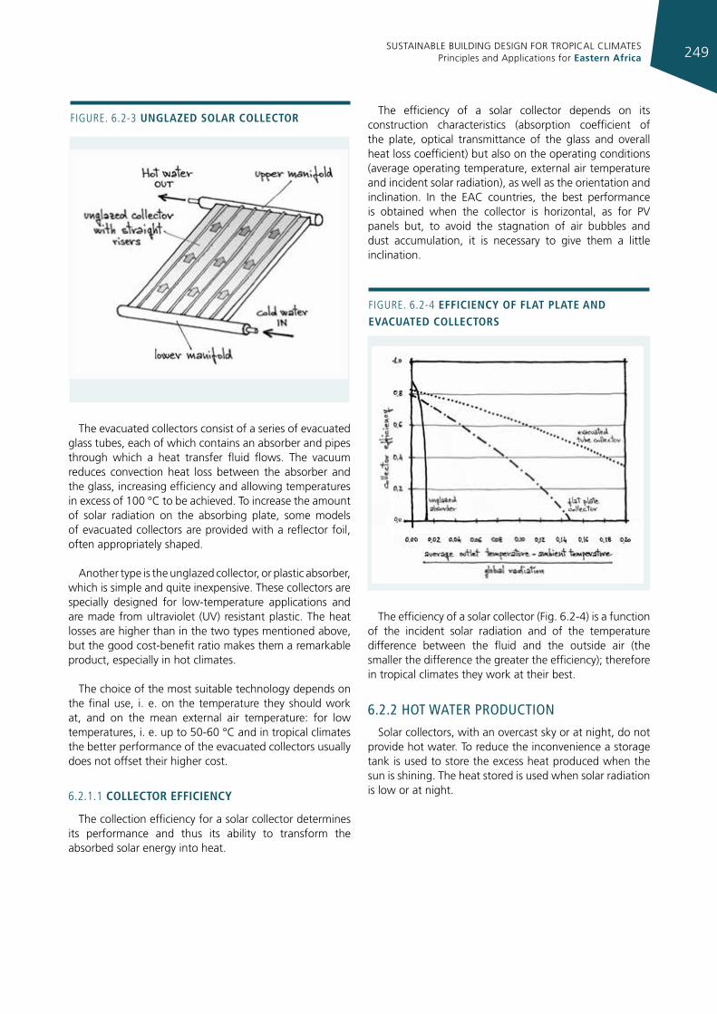
SUSTAINABLE BUILDING DESIGN FOR TROPICAL CLIMATES Principles and Applications for Eastern Africa 249
The evacuated collectors consist of a series of evacuated glass tubes, each of which contains an absorber and pipes through which a heat transfer fluid flows. The vacuum reduces convection heat loss between the absorber and the glass, increasing efficiency and allowing temperatures in excess of 100 °C to be achieved. To increase the amount of solar radiation on the absorbing plate, some models of evacuated collectors are provided with a reflector foil, often appropriately shaped.
Another type is the unglazed collector, or plastic absorber, which is simple and quite inexpensive. These collectors are specially designed for low-temperature applications and are made from ultraviolet (UV) resistant plastic. The heat losses are higher than in the two types mentioned above, but the good cost-benefit ratio makes them a remarkable product, especially in hot climates.
The choice of the most suitable technology depends on the final use, i. e. on the temperature they should work at, and on the mean external air temperature: for low temperatures, i. e. up to 50-60 °C and in tropical climates the better performance of the evacuated collectors usually does not offset their higher cost.
6.2.1.1 collector effIcIency
The collection efficiency for a solar collector determines its performance and thus its ability to transform the absorbed solar energy into heat.
The efficiency of a solar collector depends on its construction characteristics (absorption coefficient of the plate, optical transmittance of the glass and overall heat loss coefficient) but also on the operating conditions (average operating temperature, external air temperature and incident solar radiation), as well as the orientation and inclination. In the EAC countries, the best performance is obtained when the collector is horizontal, as for PV panels but, to avoid the stagnation of air bubbles and dust accumulation, it is necessary to give them a little inclination.
The efficiency of a solar collector (Fig. 6.2-4) is a function of the incident solar radiation and of the temperature difference between the fluid and the outside air (the smaller the difference the greater the efficiency); therefore in tropical climates they work at their best.
6.2.2 hoT waTer producTIon
Solar collectors, with an overcast sky or at night, do not provide hot water. To reduce the inconvenience a storage tank is used to store the excess heat produced when the sun is shining. The heat stored is used when solar radiation is low or at night.
Figure. 6.2-3 unglazed solar collector
Figure. 6.2-4 effIcIency of flat plate and evacuated collectors
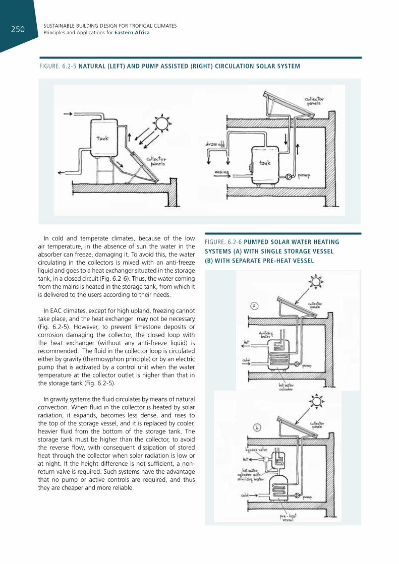
SUSTAINABLE BUILDING DESIGN FOR TROPICAL CLIMATES Principles and Applications for Eastern Africa250
In cold and temperate climates, because of the low air temperature, in the absence of sun the water in the absorber can freeze, damaging it. To avoid this, the water circulating in the collectors is mixed with an anti-freeze liquid and goes to a heat exchanger situated in the storage tank, in a closed circuit (Fig. 6.2-6). Thus, the water coming from the mains is heated in the storage tank, from which it is delivered to the users according to their needs.
In EAC climates, except for high upland, freezing cannot take place, and the heat exchanger may not be necessary (Fig. 6.2-5). However, to prevent limestone deposits or corrosion damaging the collector, the closed loop with the heat exchanger (without any anti-freeze liquid) is recommended. The fluid in the collector loop is circulated either by gravity (thermosyphon principle) or by an electric pump that is activated by a control unit when the water temperature at the collector outlet is higher than that in the storage tank (Fig. 6.2-5).
In gravity systems the fluid circulates by means of natural convection. When fluid in the collector is heated by solar radiation, it expands, becomes less dense, and rises to the top of the storage vessel, and it is replaced by cooler, heavier fluid from the bottom of the storage tank. The storage tank must be higher than the collector, to avoid the reverse flow, with consequent dissipation of stored heat through the collector when solar radiation is low or at night. If the height difference is not sufficient, a non-return valve is required. Such systems have the advantage that no pump or active controls are required, and thus they are cheaper and more reliable.
Figure. 6.2-5 natural (left) and pump assIsted (rIght) cIrculatIon solar system
Figure. 6.2-6 pumped solar Water heatIng systems (a) WIth sIngle storage vessel (b) WIth separate pre-heat vessel
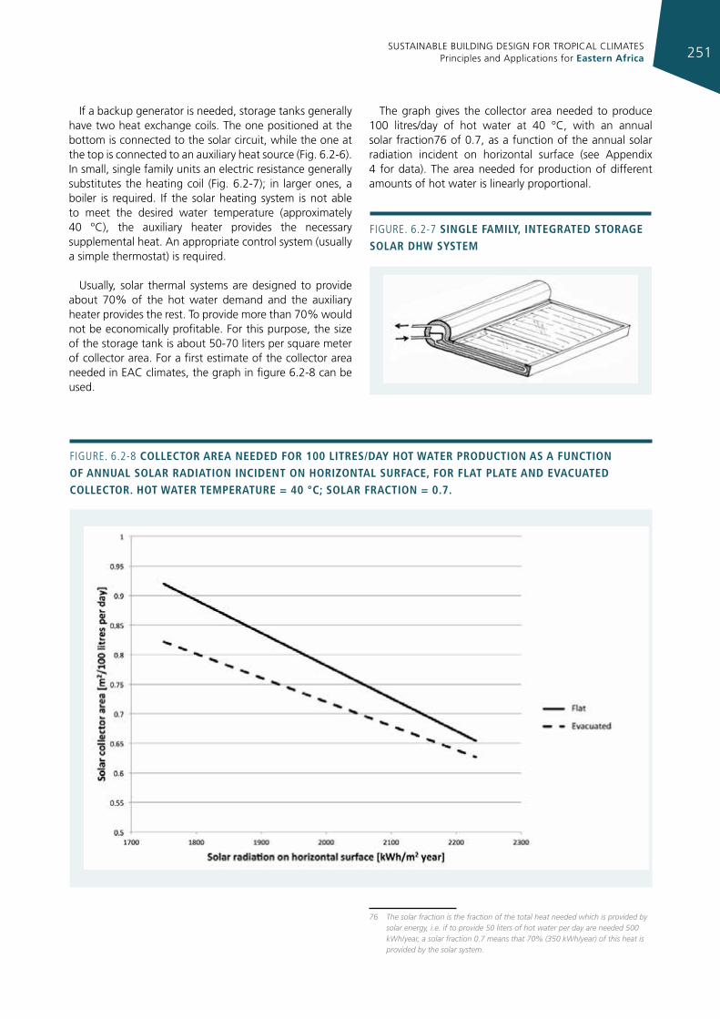
SUSTAINABLE BUILDING DESIGN FOR TROPICAL CLIMATES Principles and Applications for Eastern Africa 251
If a backup generator is needed, storage tanks generally have two heat exchange coils. The one positioned at the bottom is connected to the solar circuit, while the one at the top is connected to an auxiliary heat source (Fig. 6.2-6). In small, single family units an electric resistance generally substitutes the heating coil (Fig. 6.2-7); in larger ones, a boiler is required. If the solar heating system is not able to meet the desired water temperature (approximately 40 °C), the auxiliary heater provides the necessary supplemental heat. An appropriate control system (usually a simple thermostat) is required.
Usually, solar thermal systems are designed to provide about 70% of the hot water demand and the auxiliary heater provides the rest. To provide more than 70% would not be economically profitable. For this purpose, the size of the storage tank is about 50-70 liters per square meter of collector area. For a first estimate of the collector area needed in EAC climates, the graph in figure 6.2-8 can be used.
The graph gives the collector area needed to produce 100 litres/day of hot water at 40 °C, with an annual solar fraction76 of 0.7, as a function of the annual solar radiation incident on horizontal surface (see Appendix 4 for data). The area needed for production of different amounts of hot water is linearly proportional.
76 The solar fraction is the fraction of the total heat needed which is provided by solar energy, i.e. if to provide 50 liters of hot water per day are needed 500 kWh/year, a solar fraction 0.7 means that 70% (350 kWh/year) of this heat is provided by the solar system.
Figure. 6.2-8 collector area needed for 100 lItres/day hot Water productIon as a functIon of annual solar radIatIon IncIdent on horIzontal surface, for flat plate and evacuated collector. hot Water temperature = 40 °c; solar fractIon = 0.7.
Figure. 6.2-7 sIngle famIly, Integrated storage solar dhW system
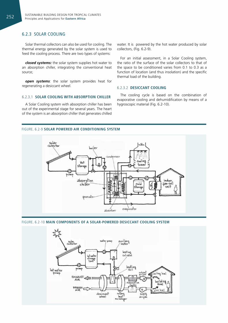
SUSTAINABLE BUILDING DESIGN FOR TROPICAL CLIMATES Principles and Applications for Eastern Africa252
Figure. 6.2-9 solar poWered aIr condItIonIng system
6.2.3 solar coolIng
Solar thermal collectors can also be used for cooling. The thermal energy generated by the solar system is used to feed the cooling process. There are two types of systems:
closed systems: the solar system supplies hot water to an absorption chiller, integrating the conventional heat source;
open systems: the solar system provides heat for regenerating a desiccant wheel.
6.2.3.1 solar coolIng WIth absorptIon chIller
A Solar Cooling system with absorption chiller has been out of the experimental stage for several years. The heart of the system is an absorption chiller that generates chilled
water. It is powered by the hot water produced by solar collectors, (Fig. 6.2-9).
For an initial assessment, in a Solar Cooling system, the ratio of the surface of the solar collectors to that of the space to be conditioned varies from 0.1 to 0.3 as a function of location (and thus insolation) and the specific thermal load of the building.
6.2.3.2 desIccant coolIng
The cooling cycle is based on the combination of evaporative cooling and dehumidification by means of a hygroscopic material (Fig. 6.2-10).
Figure. 6.2-10 maIn components of a solar-poWered desIccant coolIng system
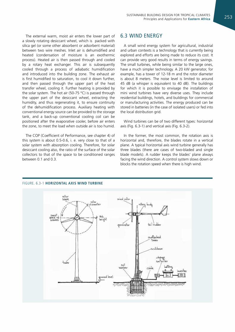
SUSTAINABLE BUILDING DESIGN FOR TROPICAL CLIMATES Principles and Applications for Eastern Africa 253
The external warm, moist air enters the lower part of a slowly rotating desiccant wheel, which is packed with silica gel (or some other absorbent or adsorbent material) between two wire meshes. Inlet air is dehumidified and heated (condensation of moisture is an exothermic process). Heated air is then passed through and cooled by a rotary heat exchanger. This air is subsequently cooled through a process of adiabatic humidification and introduced into the building zone. The exhaust air is first humidified to saturation, to cool it down further, and then passed through the upper part of the heat transfer wheel, cooling it. Further heating is provided by the solar system. The hot air (50-75 °C) is passed through the upper part of the desiccant wheel, extracting the humidity, and thus regenerating it, to ensure continuity of the dehumidification process. Auxiliary heating with conventional energy source can be provided to the storage tank, and a back-up conventional cooling coil can be positioned after the evaporative cooler, before air enters the zone, to meet the load when outside air is too humid.
The COP (Coefficient of Performance, see chapter 4) of this system is about 0.5-0.6, i. e. very close to that of a solar system with absorption cooling. Therefore, for solar desiccant cooling also, the ratio of the surface of the solar collectors to that of the space to be conditioned ranges between 0.1 and 0.3.
6.3 wInd energy
A small wind energy system for agricultural, industrial and urban contexts is a technology that is currently being explored and efforts are being made to reduce its cost. It can provide very good results in terms of energy savings. The small turbines, while being similar to the large ones, have a much simpler technology. A 20 kW generator, for example, has a tower of 12-18 m and the rotor diameter is about 8 meters. The noise level is limited to around 45 dB (a whisper is equivalent to 40 dB). The buildings for which it is possible to envisage the installation of mini wind turbines have very diverse uses. They include residential buildings, hotels, and buildings for commercial or manufacturing activities. The energy produced can be stored in batteries (in the case of isolated users) or fed into the local distribution grid.
Wind turbines can be of two different types: horizontal axis (Fig. 6.3-1) and vertical axis (Fig. 6.3-2).
In the former, the most common, the rotation axis is horizontal and, therefore, the blades rotate in a vertical plane. A typical horizontal axis wind turbine generally has three blades (there are cases of two-bladed and single blade models). A rudder keeps the blades’ plane always facing the wind direction. A control system slows down or blocks the rotation speed when there is high wind.
Figure. 6.3-1 horIzontal axIs WInd turbIne
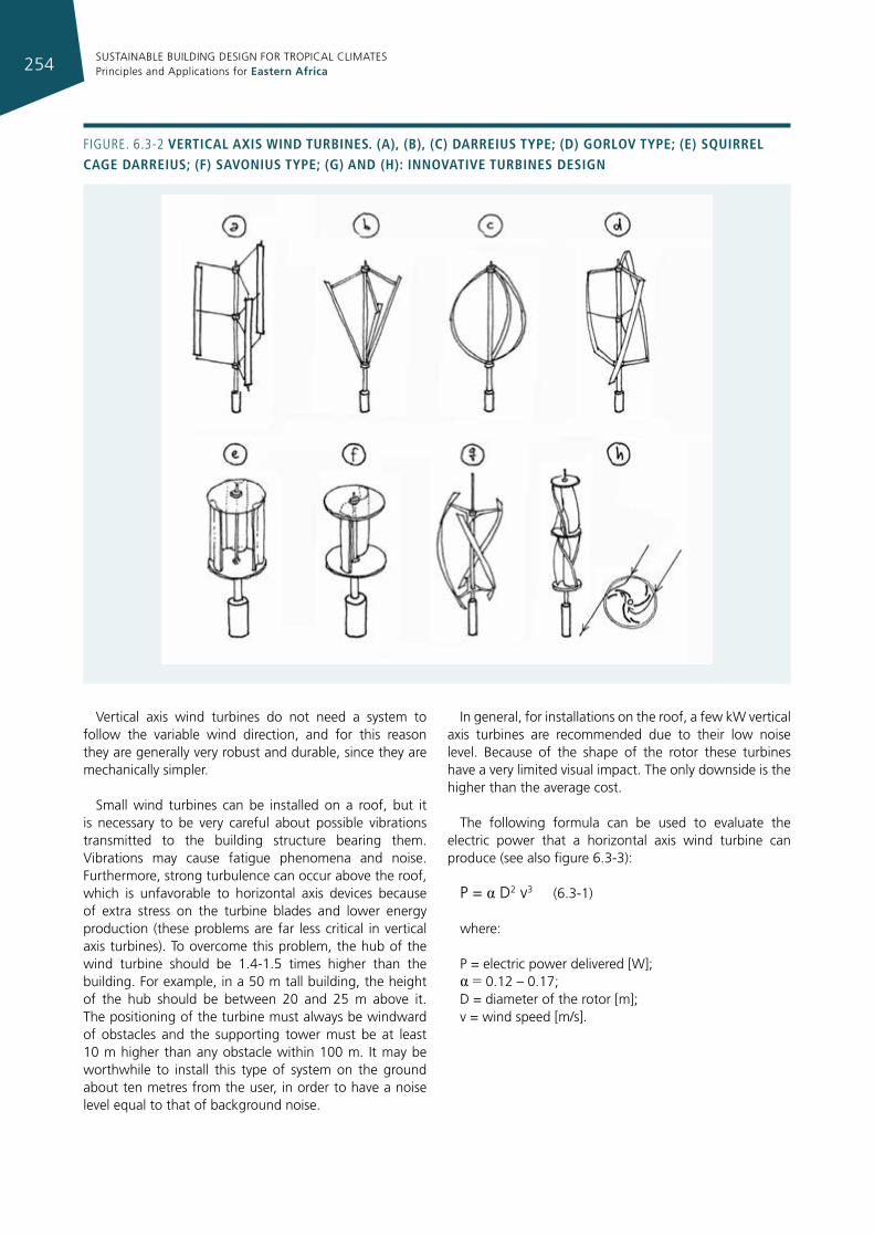
SUSTAINABLE BUILDING DESIGN FOR TROPICAL CLIMATES Principles and Applications for Eastern Africa254
Figure. 6.3-2 vertIcal axIs WInd turbInes. (a), (b), (c) darreIus type; (d) gorlov type; (e) squIrrel cage darreIus; (f) savonIus type; (g) and (h): InnovatIve turbInes desIgn
Vertical axis wind turbines do not need a system to follow the variable wind direction, and for this reason they are generally very robust and durable, since they are mechanically simpler.
Small wind turbines can be installed on a roof, but it is necessary to be very careful about possible vibrations transmitted to the building structure bearing them. Vibrations may cause fatigue phenomena and noise. Furthermore, strong turbulence can occur above the roof, which is unfavorable to horizontal axis devices because of extra stress on the turbine blades and lower energy production (these problems are far less critical in vertical axis turbines). To overcome this problem, the hub of the wind turbine should be 1.4-1.5 times higher than the building. For example, in a 50 m tall building, the height of the hub should be between 20 and 25 m above it. The positioning of the turbine must always be windward of obstacles and the supporting tower must be at least 10 m higher than any obstacle within 100 m. It may be worthwhile to install this type of system on the ground about ten metres from the user, in order to have a noise level equal to that of background noise.
In general, for installations on the roof, a few kW vertical axis turbines are recommended due to their low noise level. Because of the shape of the rotor these turbines have a very limited visual impact. The only downside is the higher than the average cost.
The following formula can be used to evaluate the electric power that a horizontal axis wind turbine can produce (see also figure 6.3-3):
P = α D2 v3 (6.3-1)
where:
P = electric power delivered [W];α = 0.12 – 0.17;D = diameter of the rotor [m];v = wind speed [m/s].
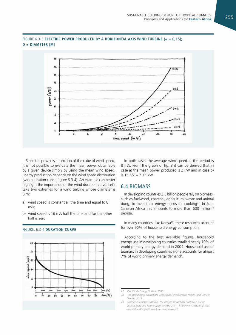
SUSTAINABLE BUILDING DESIGN FOR TROPICAL CLIMATES Principles and Applications for Eastern Africa 255
Since the power is a function of the cube of wind speed, it is not possible to evaluate the mean power obtainable by a given device simply by using the mean wind speed. Energy production depends on the wind speed distribution (wind duration curve, figure 6.3-4). An example can better highlight the importance of the wind duration curve. Let’s take two extremes for a wind turbine whose diameter is 5 m:
a) wind speed is constant all the time and equal to 8 m/s;
b) wind speed is 16 m/s half the time and for the other half is zero.
In both cases the average wind speed in the period is 8 m/s. From the graph of fig. 3 it can be derived that in case a) the mean power produced is 2 kW and in case b) is 15.5/2 = 7.75 kW.
6.4 bIomassIn developing countries 2.5 billion people rely on biomass,
such as fuelwood, charcoal, agricultural waste and animal dung, to meet their energy needs for cooking77. In Sub-Saharan Africa this amounts to more than 600 million78 people.
In many countries, like Kenya79, these resources account for over 90% of household energy consumption.
According to the best available figures, household energy use in developing countries totalled nearly 10% of world primary energy demand in 2004. Household use of biomass in developing countries alone accounts for almost 7% of world primary energy demand1.
77 IEA, World Energy Outlook 200678 The World Bank, Household Cookstoves, Environment, Health, and Climate
Change, 201179 Winrock International/USAID, The Kenyan Household Cookstove Sector:
Current State and Future Opportunities, 2011 - http://www.relwa.org/sites/default/files/Kenya-Stoves-Assessment-web.pdf
Figure. 6.3-4 duratIon curve
Figure 6.3-3 electrIc poWer produced by a horIzontal axIs WInd turbIne (α = 0,15); d = dIameter [m]
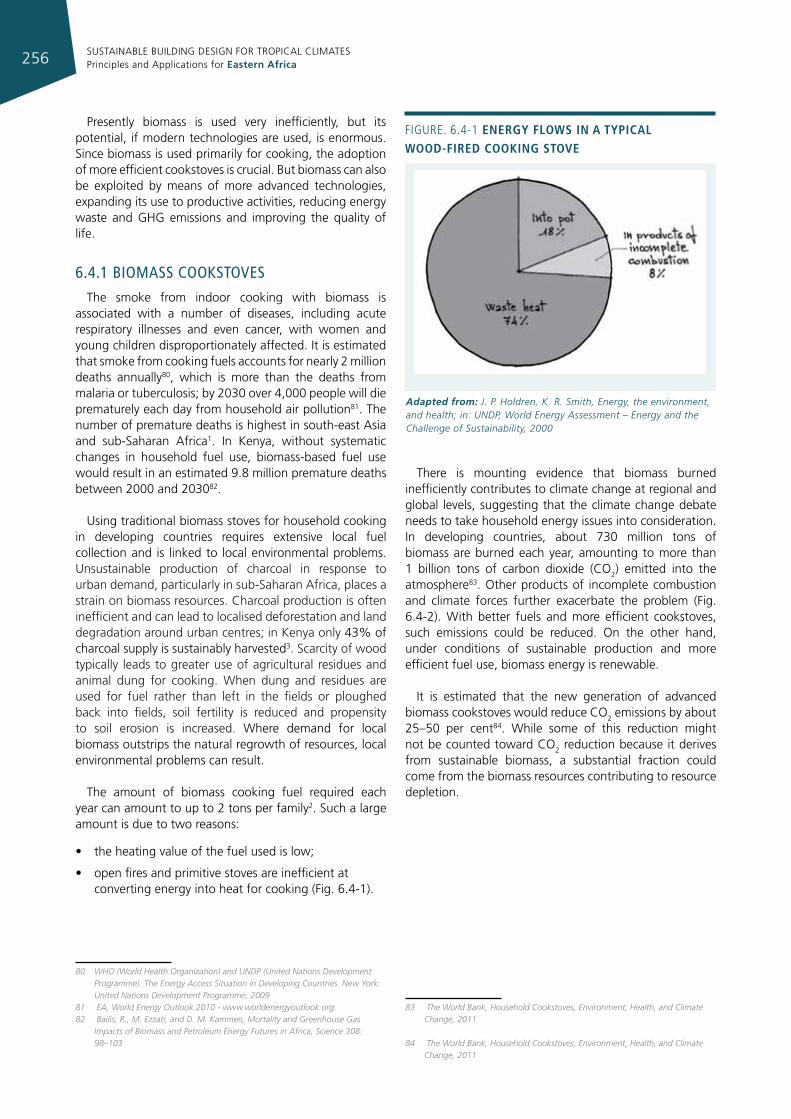
SUSTAINABLE BUILDING DESIGN FOR TROPICAL CLIMATES Principles and Applications for Eastern Africa256
Presently biomass is used very inefficiently, but its potential, if modern technologies are used, is enormous. Since biomass is used primarily for cooking, the adoption of more efficient cookstoves is crucial. But biomass can also be exploited by means of more advanced technologies, expanding its use to productive activities, reducing energy waste and GHG emissions and improving the quality of life.
6.4.1 bIomass cooksToves
The smoke from indoor cooking with biomass is associated with a number of diseases, including acute respiratory illnesses and even cancer, with women and young children disproportionately affected. It is estimated that smoke from cooking fuels accounts for nearly 2 million deaths annually80, which is more than the deaths from malaria or tuberculosis; by 2030 over 4,000 people will die prematurely each day from household air pollution81. The number of premature deaths is highest in south-east Asia and sub-Saharan Africa1. In Kenya, without systematic changes in household fuel use, biomass-based fuel use would result in an estimated 9.8 million premature deaths between 2000 and 203082.
Using traditional biomass stoves for household cooking in developing countries requires extensive local fuel collection and is linked to local environmental problems. Unsustainable production of charcoal in response to urban demand, particularly in sub-Saharan Africa, places a strain on biomass resources. Charcoal production is often inefficient and can lead to localised deforestation and land degradation around urban centres; in Kenya only 43% of charcoal supply is sustainably harvested3. Scarcity of wood typically leads to greater use of agricultural residues and animal dung for cooking. When dung and residues are used for fuel rather than left in the fields or ploughed back into fields, soil fertility is reduced and propensity to soil erosion is increased. Where demand for local biomass outstrips the natural regrowth of resources, local environmental problems can result.
The amount of biomass cooking fuel required each year can amount to up to 2 tons per family2. Such a large amount is due to two reasons:
• the heating value of the fuel used is low;
• open fires and primitive stoves are inefficient at converting energy into heat for cooking (Fig. 6.4-1).
80 WHO (World Health Organization) and UNDP (United Nations Development Programme). The Energy Access Situation in Developing Countries. New York: United Nations Development Programme, 2009
81 EA, World Energy Outlook 2010 - www.worldenergyoutlook.org.82 Bailis, R., M. Ezzati, and D. M. Kammen, Mortality and Greenhouse Gas
Impacts of Biomass and Petroleum Energy Futures in Africa, Science 308: 98–103
There is mounting evidence that biomass burned inefficiently contributes to climate change at regional and global levels, suggesting that the climate change debate needs to take household energy issues into consideration. In developing countries, about 730 million tons of biomass are burned each year, amounting to more than 1 billion tons of carbon dioxide (CO2) emitted into the atmosphere83. Other products of incomplete combustion and climate forces further exacerbate the problem (Fig. 6.4-2). With better fuels and more efficient cookstoves, such emissions could be reduced. On the other hand, under conditions of sustainable production and more efficient fuel use, biomass energy is renewable.
It is estimated that the new generation of advanced biomass cookstoves would reduce CO2 emissions by about 25–50 per cent84. While some of this reduction might not be counted toward CO2 reduction because it derives from sustainable biomass, a substantial fraction could come from the biomass resources contributing to resource depletion.
83 The World Bank, Household Cookstoves, Environment, Health, and Climate Change, 2011
84 The World Bank, Household Cookstoves, Environment, Health, and Climate Change, 2011
Figure. 6.4-1 energy floWs In a typIcal Wood-fIred cookIng stove
Adapted from: J. P. Holdren, K. R. Smith, Energy, the environment, and health; in: UNDP, World Energy Assessment – Energy and the Challenge of Sustainability, 2000
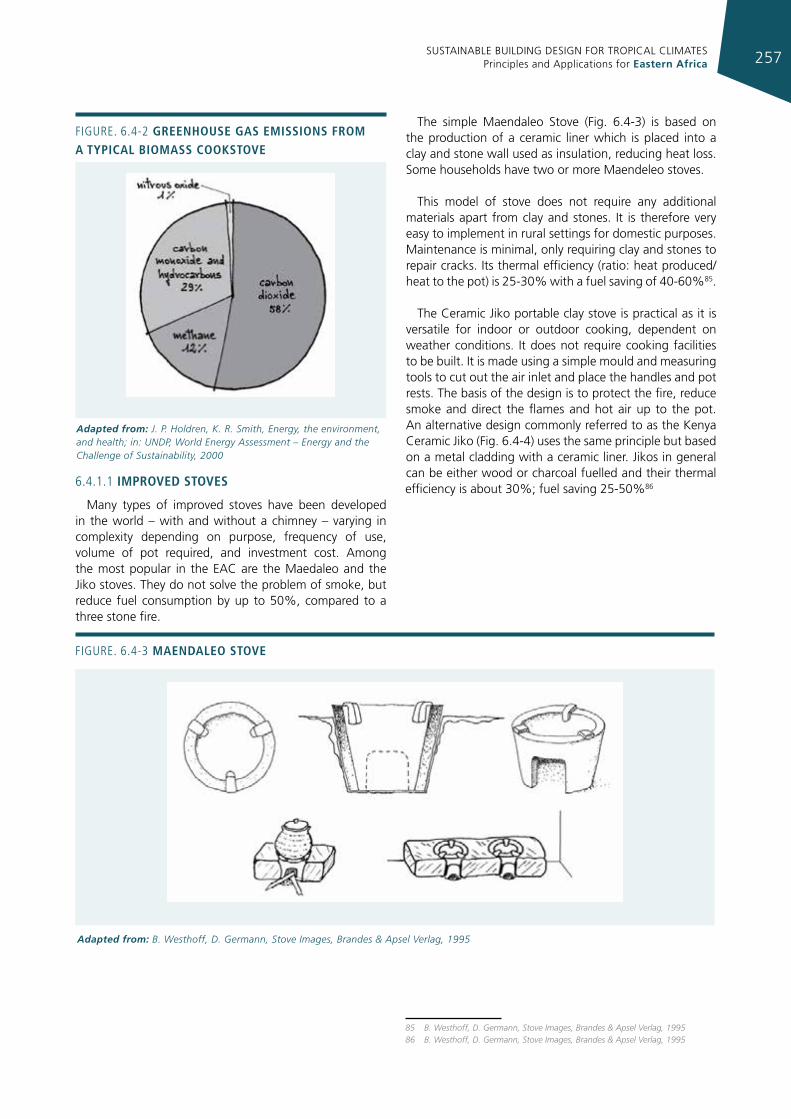
SUSTAINABLE BUILDING DESIGN FOR TROPICAL CLIMATES Principles and Applications for Eastern Africa 257
Figure. 6.4-2 greenhouse gas emIssIons from a typIcal bIomass cookstove
Adapted from: J. P. Holdren, K. R. Smith, Energy, the environment, and health; in: UNDP, World Energy Assessment – Energy and the Challenge of Sustainability, 2000
6.4.1.1 Improved stoves
Many types of improved stoves have been developed in the world – with and without a chimney – varying in complexity depending on purpose, frequency of use, volume of pot required, and investment cost. Among the most popular in the EAC are the Maedaleo and the Jiko stoves. They do not solve the problem of smoke, but reduce fuel consumption by up to 50%, compared to a three stone fire.
The simple Maendaleo Stove (Fig. 6.4-3) is based on the production of a ceramic liner which is placed into a clay and stone wall used as insulation, reducing heat loss. Some households have two or more Maendeleo stoves.
This model of stove does not require any additional materials apart from clay and stones. It is therefore very easy to implement in rural settings for domestic purposes. Maintenance is minimal, only requiring clay and stones to repair cracks. Its thermal efficiency (ratio: heat produced/heat to the pot) is 25-30% with a fuel saving of 40-60%85.
The Ceramic Jiko portable clay stove is practical as it is versatile for indoor or outdoor cooking, dependent on weather conditions. It does not require cooking facilities to be built. It is made using a simple mould and measuring tools to cut out the air inlet and place the handles and pot rests. The basis of the design is to protect the fire, reduce smoke and direct the flames and hot air up to the pot. An alternative design commonly referred to as the Kenya Ceramic Jiko (Fig. 6.4-4) uses the same principle but based on a metal cladding with a ceramic liner. Jikos in general can be either wood or charcoal fuelled and their thermal efficiency is about 30%; fuel saving 25-50%86
85 B. Westhoff, D. Germann, Stove Images, Brandes & Apsel Verlag, 199586 B. Westhoff, D. Germann, Stove Images, Brandes & Apsel Verlag, 1995
Figure. 6.4-3 maendaleo stove
Adapted from: B. Westhoff, D. Germann, Stove Images, Brandes & Apsel Verlag, 1995
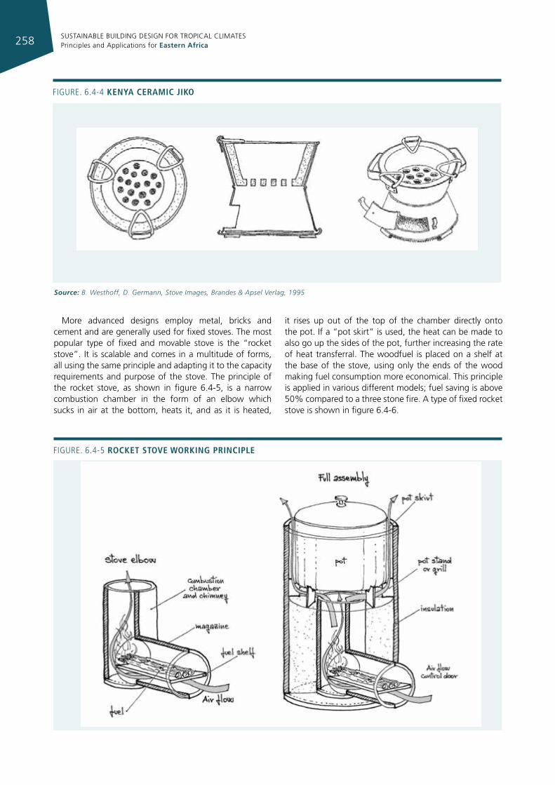
SUSTAINABLE BUILDING DESIGN FOR TROPICAL CLIMATES Principles and Applications for Eastern Africa258
Figure. 6.4-5 rocket stove WorkIng prIncIple
Figure. 6.4-4 kenya ceramIc jIko
Source: B. Westhoff, D. Germann, Stove Images, Brandes & Apsel Verlag, 1995
More advanced designs employ metal, bricks and cement and are generally used for fixed stoves. The most popular type of fixed and movable stove is the “rocket stove”. It is scalable and comes in a multitude of forms, all using the same principle and adapting it to the capacity requirements and purpose of the stove. The principle of the rocket stove, as shown in figure 6.4-5, is a narrow combustion chamber in the form of an elbow which sucks in air at the bottom, heats it, and as it is heated,
it rises up out of the top of the chamber directly onto the pot. If a “pot skirt” is used, the heat can be made to also go up the sides of the pot, further increasing the rate of heat transferral. The woodfuel is placed on a shelf at the base of the stove, using only the ends of the wood making fuel consumption more economical. This principle is applied in various different models; fuel saving is above 50% compared to a three stone fire. A type of fixed rocket stove is shown in figure 6.4-6.
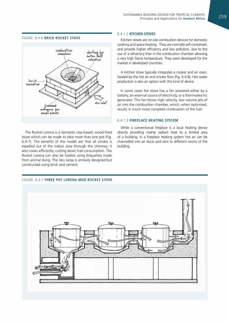
SUSTAINABLE BUILDING DESIGN FOR TROPICAL CLIMATES Principles and Applications for Eastern Africa 259
The Rocket Lorena is a domestic clay-based, wood-fired stove which can be made to take more than one pot (Fig. 6.4-7). The benefits of the model are that all smoke is expelled out of the indoor area through the chimney; it also cooks efficiently, cutting down fuel consumption. The Rocket Lorena can also be fuelled using briquettes made from animal dung. The Jiko Janja is similarly designed but constructed using brick and cement.
6.4.1.2 kItchen stoves
Kitchen stoves are on-site combustion devices for domestic cooking and space heating. They are normally self-contained, and provide higher efficiency and low pollution, due to the use of a refractory liner in the combustion chamber allowing a very high flame temperature. They were developed for the market in developed countries.
A kitchen stove typically integrates a cooker and an oven, heated by the hot air and smoke flow (Fig. 6.4-8). Hot water production is also an option with this kind of device.
In some cases the stove has a fan powered either by a battery, an external source of electricity, or a thermoelectric generator. This fan blows high velocity, low volume jets of air into the combustion chamber, which, when optimized, results in much more complete combustion of the fuel.
6.4.1.3 fIreplace heatIng system
While a conventional fireplace is a local heating device directly providing mainly radiant heat to a limited area of a building, in a fireplace heating system hot air can be channelled into air ducts and sent to different rooms of the building.
Figure. 6.4-6 brIck rocket stove
Figure. 6.4-7 three pot lorena mud rocket stove
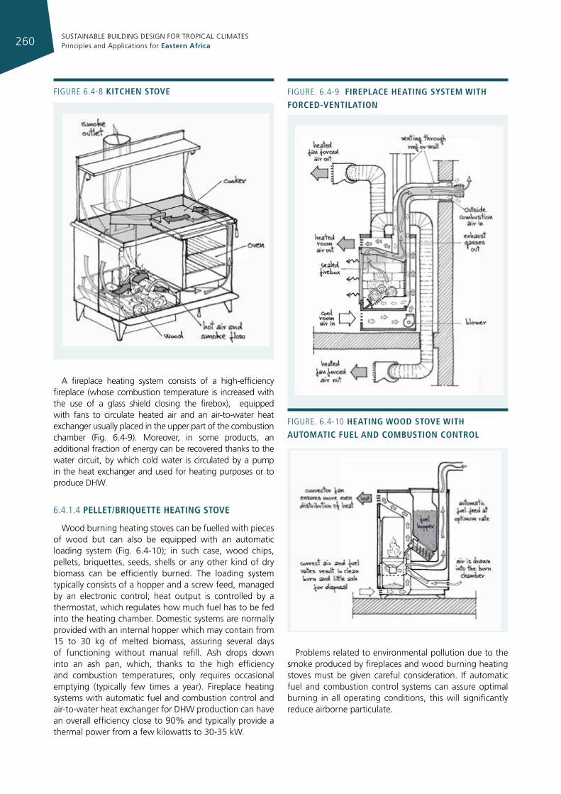
SUSTAINABLE BUILDING DESIGN FOR TROPICAL CLIMATES Principles and Applications for Eastern Africa260
A fireplace heating system consists of a high-efficiency fireplace (whose combustion temperature is increased with the use of a glass shield closing the firebox), equipped with fans to circulate heated air and an air-to-water heat exchanger usually placed in the upper part of the combustion chamber (Fig. 6.4-9). Moreover, in some products, an additional fraction of energy can be recovered thanks to the water circuit, by which cold water is circulated by a pump in the heat exchanger and used for heating purposes or to produce DHW.
6.4.1.4 pellet/brIquette heatIng stove
Wood burning heating stoves can be fuelled with pieces of wood but can also be equipped with an automatic loading system (Fig. 6.4-10); in such case, wood chips, pellets, briquettes, seeds, shells or any other kind of dry biomass can be efficiently burned. The loading system typically consists of a hopper and a screw feed, managed by an electronic control; heat output is controlled by a thermostat, which regulates how much fuel has to be fed into the heating chamber. Domestic systems are normally provided with an internal hopper which may contain from 15 to 30 kg of melted biomass, assuring several days of functioning without manual refill. Ash drops down into an ash pan, which, thanks to the high efficiency and combustion temperatures, only requires occasional emptying (typically few times a year). Fireplace heating systems with automatic fuel and combustion control and air-to-water heat exchanger for DHW production can have an overall efficiency close to 90% and typically provide a thermal power from a few kilowatts to 30-35 kW.
Problems related to environmental pollution due to the smoke produced by fireplaces and wood burning heating stoves must be given careful consideration. If automatic fuel and combustion control systems can assure optimal burning in all operating conditions, this will significantly reduce airborne particulate.
Figure 6.4-8 kItchen stove Figure. 6.4-9 fIreplace heatIng system WIth forced-ventIlatIon
Figure. 6.4-10 heatIng Wood stove WIth automatIc fuel and combustIon control
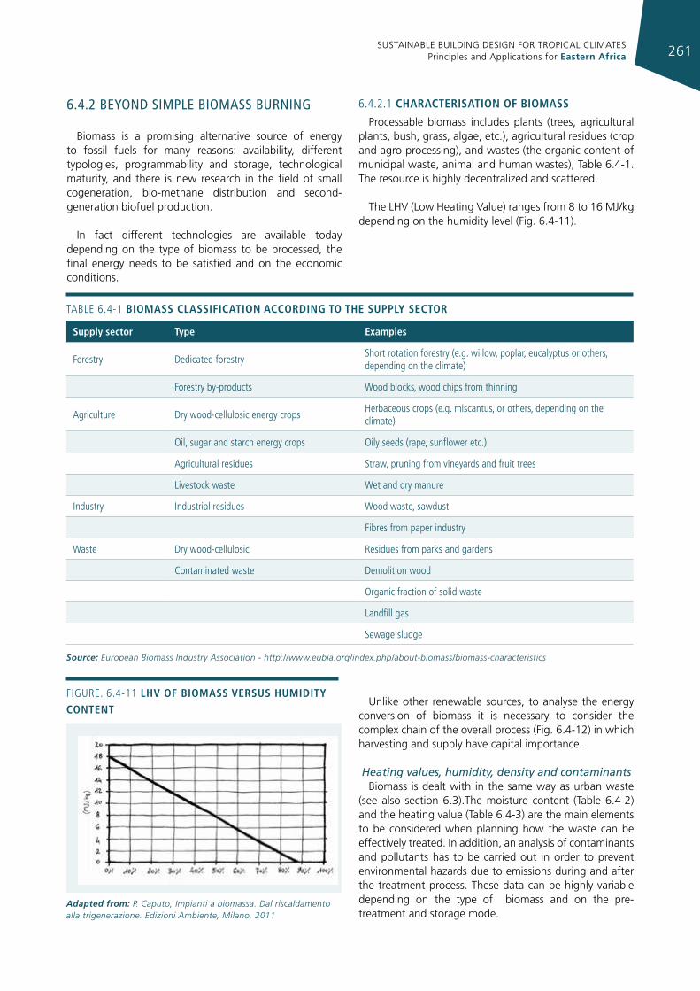
SUSTAINABLE BUILDING DESIGN FOR TROPICAL CLIMATES Principles and Applications for Eastern Africa 261
6.4.2 beyond sImple bIomass burnIng
Biomass is a promising alternative source of energy to fossil fuels for many reasons: availability, different typologies, programmability and storage, technological maturity, and there is new research in the field of small cogeneration, bio-methane distribution and second-generation biofuel production.
In fact different technologies are available today depending on the type of biomass to be processed, the final energy needs to be satisfied and on the economic conditions.
6.4.2.1 characterIsatIon of bIomass
Processable biomass includes plants (trees, agricultural plants, bush, grass, algae, etc.), agricultural residues (crop and agro-processing), and wastes (the organic content of municipal waste, animal and human wastes), Table 6.4-1. The resource is highly decentralized and scattered.
The LHV (Low Heating Value) ranges from 8 to 16 MJ/kg depending on the humidity level (Fig. 6.4-11).
Figure. 6.4-11 lhv of bIomass versus humIdIty content
Adapted from: P. Caputo, Impianti a biomassa. Dal riscaldamento alla trigenerazione. Edizioni Ambiente, Milano, 2011
supply sector type examples
Forestry Dedicated forestry Short rotation forestry (e.g. willow, poplar, eucalyptus or others, depending on the climate)
Forestry by-products Wood blocks, wood chips from thinning
Agriculture Dry wood-cellulosic energy crops Herbaceous crops (e.g. miscantus, or others, depending on the climate)
Oil, sugar and starch energy crops Oily seeds (rape, sunflower etc.)
Agricultural residues Straw, pruning from vineyards and fruit trees
Livestock waste Wet and dry manure
industry industrial residues Wood waste, sawdust
Fibres from paper industry
Waste Dry wood-cellulosic residues from parks and gardens
Contaminated waste Demolition wood
Organic fraction of solid waste
Landfill gas
Sewage sludge
TABLe 6.4-1 bIomass classIfIcatIon accordIng to the supply sector
Source: European Biomass Industry Association - http://www.eubia.org/index.php/about-biomass/biomass-characteristics
Unlike other renewable sources, to analyse the energy conversion of biomass it is necessary to consider the complex chain of the overall process (Fig. 6.4-12) in which harvesting and supply have capital importance.
Heating values, humidity, density and contaminantsBiomass is dealt with in the same way as urban waste
(see also section 6.3).The moisture content (Table 6.4-2) and the heating value (Table 6.4-3) are the main elements to be considered when planning how the waste can be effectively treated. In addition, an analysis of contaminants and pollutants has to be carried out in order to prevent environmental hazards due to emissions during and after the treatment process. These data can be highly variable depending on the type of biomass and on the pre-treatment and storage mode.
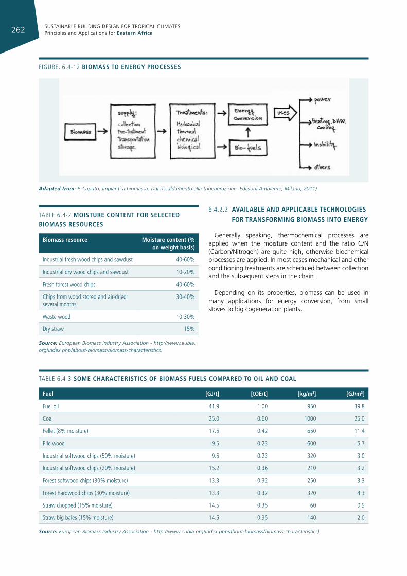
SUSTAINABLE BUILDING DESIGN FOR TROPICAL CLIMATES Principles and Applications for Eastern Africa262
Figure. 6.4-12 bIomass to energy processes
Adapted from: P. Caputo, Impianti a biomassa. Dal riscaldamento alla trigenerazione. Edizioni Ambiente, Milano, 2011)
6.4.2.2 avaIlable and applIcable technologIes
for transformIng bIomass Into energy
Generally speaking, thermochemical processes are applied when the moisture content and the ratio C/N (Carbon/Nitrogen) are quite high, otherwise biochemical processes are applied. In most cases mechanical and other conditioning treatments are scheduled between collection and the subsequent steps in the chain.
Depending on its properties, biomass can be used in many applications for energy conversion, from small stoves to big cogeneration plants.
fuel [gj/t] [toe/t] [kg/m3] [gj/m3]
Fuel oil 41.9 1.00 950 39.8
Coal 25.0 0.60 1000 25.0
Pellet (8% moisture) 17.5 0.42 650 11.4
Pile wood 9.5 0.23 600 5.7
industrial softwood chips (50% moisture) 9.5 0.23 320 3.0
industrial softwood chips (20% moisture) 15.2 0.36 210 3.2
Forest softwood chips (30% moisture) 13.3 0.32 250 3.3
Forest hardwood chips (30% moisture) 13.3 0.32 320 4.3
Straw chopped (15% moisture) 14.5 0.35 60 0.9
Straw big bales (15% moisture) 14.5 0.35 140 2.0
TABLe 6.4-3 some characterIstIcs of bIomass fuels compared to oIl and coal
Source: European Biomass Industry Association - http://www.eubia.org/index.php/about-biomass/biomass-characteristics)
TABLe 6.4-2 moIsture content for selected bIomass resources
biomass resource moisture content (% on weight basis)
industrial fresh wood chips and sawdust 40-60%
industrial dry wood chips and sawdust 10-20%
Fresh forest wood chips 40-60%
Chips from wood stored and air-dried several months
30-40%
Waste wood 10-30%
Dry straw 15%
Source: European Biomass Industry Association - http://www.eubia.org/index.php/about-biomass/biomass-characteristics)
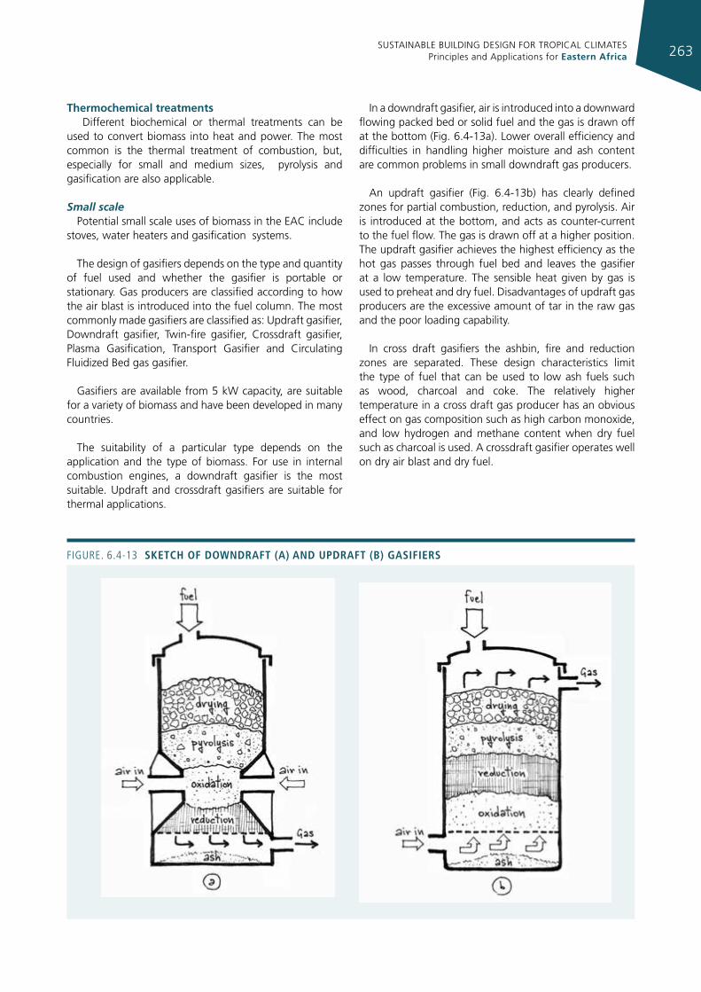
SUSTAINABLE BUILDING DESIGN FOR TROPICAL CLIMATES Principles and Applications for Eastern Africa 263
thermochemical treatments Different biochemical or thermal treatments can be
used to convert biomass into heat and power. The most common is the thermal treatment of combustion, but, especially for small and medium sizes, pyrolysis and gasification are also applicable.
Small scalePotential small scale uses of biomass in the EAC include
stoves, water heaters and gasification systems.
The design of gasifiers depends on the type and quantity of fuel used and whether the gasifier is portable or stationary. Gas producers are classified according to how the air blast is introduced into the fuel column. The most commonly made gasifiers are classified as: Updraft gasifier, Downdraft gasifier, Twin-fire gasifier, Crossdraft gasifier, Plasma Gasification, Transport Gasifier and Circulating Fluidized Bed gas gasifier.
Gasifiers are available from 5 kW capacity, are suitable for a variety of biomass and have been developed in many countries.
The suitability of a particular type depends on the application and the type of biomass. For use in internal combustion engines, a downdraft gasifier is the most suitable. Updraft and crossdraft gasifiers are suitable for thermal applications.
In a downdraft gasifier, air is introduced into a downward flowing packed bed or solid fuel and the gas is drawn off at the bottom (Fig. 6.4-13a). Lower overall efficiency and difficulties in handling higher moisture and ash content are common problems in small downdraft gas producers.
An updraft gasifier (Fig. 6.4-13b) has clearly defined zones for partial combustion, reduction, and pyrolysis. Air is introduced at the bottom, and acts as counter-current to the fuel flow. The gas is drawn off at a higher position. The updraft gasifier achieves the highest efficiency as the hot gas passes through fuel bed and leaves the gasifier at a low temperature. The sensible heat given by gas is used to preheat and dry fuel. Disadvantages of updraft gas producers are the excessive amount of tar in the raw gas and the poor loading capability.
In cross draft gasifiers the ashbin, fire and reduction zones are separated. These design characteristics limit the type of fuel that can be used to low ash fuels such as wood, charcoal and coke. The relatively higher temperature in a cross draft gas producer has an obvious effect on gas composition such as high carbon monoxide, and low hydrogen and methane content when dry fuel such as charcoal is used. A crossdraft gasifier operates well on dry air blast and dry fuel.
Figure. 6.4-13 sketch of doWndraft (a) and updraft (b) gasIfIers
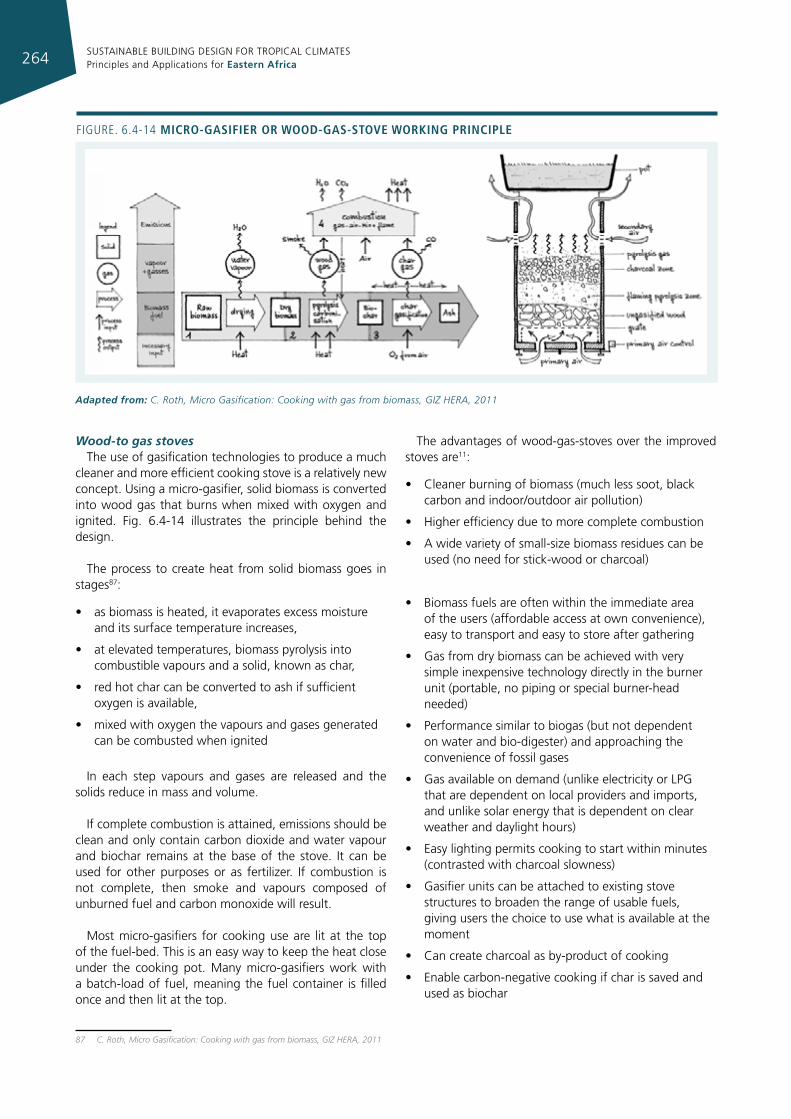
SUSTAINABLE BUILDING DESIGN FOR TROPICAL CLIMATES Principles and Applications for Eastern Africa264
Figure. 6.4-14 mIcro-gasIfIer or Wood-gas-stove WorkIng prIncIple
Adapted from: C. Roth, Micro Gasification: Cooking with gas from biomass, GIZ HERA, 2011
Wood-to gas stovesThe use of gasification technologies to produce a much
cleaner and more efficient cooking stove is a relatively new concept. Using a micro-gasifier, solid biomass is converted into wood gas that burns when mixed with oxygen and ignited. Fig. 6.4-14 illustrates the principle behind the design.
The process to create heat from solid biomass goes in stages87:
• as biomass is heated, it evaporates excess moisture and its surface temperature increases,
• at elevated temperatures, biomass pyrolysis into combustible vapours and a solid, known as char,
• red hot char can be converted to ash if sufficient oxygen is available,
• mixed with oxygen the vapours and gases generated can be combusted when ignited
In each step vapours and gases are released and the solids reduce in mass and volume.
If complete combustion is attained, emissions should be clean and only contain carbon dioxide and water vapour and biochar remains at the base of the stove. It can be used for other purposes or as fertilizer. If combustion is not complete, then smoke and vapours composed of unburned fuel and carbon monoxide will result.
Most micro-gasifiers for cooking use are lit at the top of the fuel-bed. This is an easy way to keep the heat close under the cooking pot. Many micro-gasifiers work with a batch-load of fuel, meaning the fuel container is filled once and then lit at the top.
87 C. Roth, Micro Gasification: Cooking with gas from biomass, GIZ HERA, 2011
The advantages of wood-gas-stoves over the improved stoves are11:
• Cleaner burning of biomass (much less soot, black carbon and indoor/outdoor air pollution)
• Higher efficiency due to more complete combustion
• A wide variety of small-size biomass residues can be used (no need for stick-wood or charcoal)
• Biomass fuels are often within the immediate area of the users (affordable access at own convenience), easy to transport and easy to store after gathering
• Gas from dry biomass can be achieved with very simple inexpensive technology directly in the burner unit (portable, no piping or special burner-head needed)
• Performance similar to biogas (but not dependent on water and bio-digester) and approaching the convenience of fossil gases
• Gas available on demand (unlike electricity or LPG that are dependent on local providers and imports, and unlike solar energy that is dependent on clear weather and daylight hours)
• Easy lighting permits cooking to start within minutes (contrasted with charcoal slowness)
• Gasifier units can be attached to existing stove structures to broaden the range of usable fuels, giving users the choice to use what is available at the moment
• Can create charcoal as by-product of cooking
• Enable carbon-negative cooking if char is saved and used as biochar
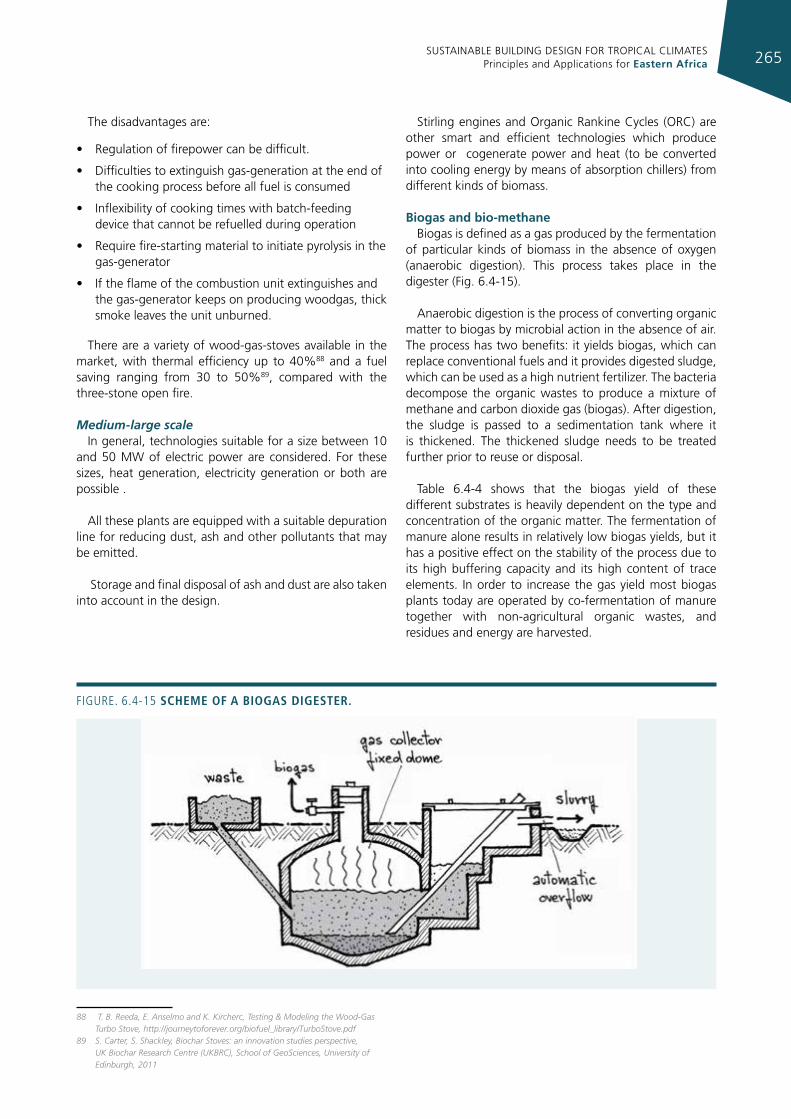
SUSTAINABLE BUILDING DESIGN FOR TROPICAL CLIMATES Principles and Applications for Eastern Africa 265
The disadvantages are:
• Regulation of firepower can be difficult.
• Difficulties to extinguish gas-generation at the end of the cooking process before all fuel is consumed
• Inflexibility of cooking times with batch-feeding device that cannot be refuelled during operation
• Require fire-starting material to initiate pyrolysis in the gas-generator
• If the flame of the combustion unit extinguishes and the gas-generator keeps on producing woodgas, thick smoke leaves the unit unburned.
There are a variety of wood-gas-stoves available in the market, with thermal efficiency up to 40%88 and a fuel saving ranging from 30 to 50%89, compared with the three-stone open fire.
Medium-large scaleIn general, technologies suitable for a size between 10
and 50 MW of electric power are considered. For these sizes, heat generation, electricity generation or both are possible .
All these plants are equipped with a suitable depuration line for reducing dust, ash and other pollutants that may be emitted.
Storage and final disposal of ash and dust are also taken into account in the design.
88 T. B. Reeda, E. Anselmo and K. Kircherc, Testing & Modeling the Wood-Gas Turbo Stove, http://journeytoforever.org/biofuel_library/TurboStove.pdf
89 S. Carter, S. Shackley, Biochar Stoves: an innovation studies perspective, UK Biochar Research Centre (UKBRC), School of GeoSciences, University of Edinburgh, 2011
Stirling engines and Organic Rankine Cycles (ORC) are other smart and efficient technologies which produce power or cogenerate power and heat (to be converted into cooling energy by means of absorption chillers) from different kinds of biomass.
biogas and bio-methaneBiogas is defined as a gas produced by the fermentation
of particular kinds of biomass in the absence of oxygen (anaerobic digestion). This process takes place in the digester (Fig. 6.4-15).
Anaerobic digestion is the process of converting organic matter to biogas by microbial action in the absence of air. The process has two benefits: it yields biogas, which can replace conventional fuels and it provides digested sludge, which can be used as a high nutrient fertilizer. The bacteria decompose the organic wastes to produce a mixture of methane and carbon dioxide gas (biogas). After digestion, the sludge is passed to a sedimentation tank where it is thickened. The thickened sludge needs to be treated further prior to reuse or disposal.
Table 6.4-4 shows that the biogas yield of these different substrates is heavily dependent on the type and concentration of the organic matter. The fermentation of manure alone results in relatively low biogas yields, but it has a positive effect on the stability of the process due to its high buffering capacity and its high content of trace elements. In order to increase the gas yield most biogas plants today are operated by co-fermentation of manure together with non-agricultural organic wastes, and residues and energy are harvested.
Figure. 6.4-15 scheme of a bIogas dIgester.
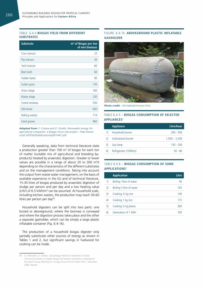
SUSTAINABLE BUILDING DESIGN FOR TROPICAL CLIMATES Principles and Applications for Eastern Africa266
Generally speaking, data from technical literature state a production greater than 100 m3 of biogas for each ton of matter (suitable mix of agricultural and breeding by-products) treated by anaerobic digestion. Greater or lower values are possible in a range of about 20 to 300 m3/t depending on the characteristics of the different substrates and on the management conditions. Taking into account the output from waste water management, on the basis of available experience in the EU and of technical literature, 15-30 litres of biogas produced by anaerobic digestion of sludge per person and per day and a low heating value (LHV) of 6.5 kWh/m3 can be assumed. At household scale, including kitchen wastes, the production may reach 30-60 litres per person per day90.
Household digesters can be split into two parts: one buried or aboveground, where the biomass is conveyed and where the digestion process takes place and the other a separate gasholder, which can be simply a large plastic inflatable container (Fig. 6.4-16).
The production of a household biogas digester only partially substitutes other sources of energy as shown in Tables 1 and 2, but significant savings in fuelwood for cooking can be made.
90 G. P.Nembrini, A. Kimaro, Using Biogas Plants for Treatment of Urban Community Wastes to Supply Energy and Improve Sanitation, presented at the Expert Group Meeting on “Energy Access for the Urban Poor”, December 2006, Nairobi
TABLe 6.4-4 bIogas yIeld from dIfferent substrates
substrate m3 of biogas per ton of wet biomass
Cow manure 25
Pig manure 30
Yard manure 60
Beet leafs 60
Fodder beets 90
Sudan grass 130
grass silage 160
Maize silage 230
Cereal residues 550
Old bread 600
Baking wastes 714
used grease 960
Adapted from: F. Cotana and D. Giraldi, Renewable energy for agricultural companies: a biogas micro-chp project - http://www.ciriaf.it/ft/File/Pubblicazioni/pdf/1447.pdf
TABLe 6.4-5 – bIogas consumptIon of selected applIances1
appliance litre/hour
1) Household burner 200 - 500
2) institutional burner 1,500 – 2,500
3) gas lamp 150 - 200
4) refrigerator (100litre) 50 - 80
TABLe 6.4-6 – bIogas consumptIon of some applIcatIons1
application litre
1) Boiling 1litre of water 40
2) Boiling 5 litre of water 165
3) Cooking ½ kg rice 140
4) Cooking 1 kg rice 175
5) Cooking ½ kg beans 300
6) generation of 1 kWh 700
Figure. 6.4-16 aboveground plastIc Inflatable gasholder
Photo credit: UN-Habitat/Vincent Kitio
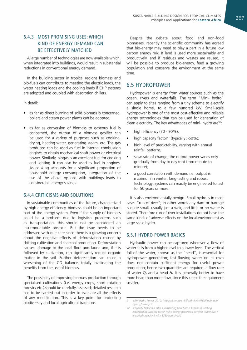
SUSTAINABLE BUILDING DESIGN FOR TROPICAL CLIMATES Principles and Applications for Eastern Africa 267
6.4.3 mosT promIsIng uses: whIch kInd of energy demand can be effecTIvely maTched
A large number of technologies are now available which, when integrated into buildings, would result in substantial reductions in conventional energy demand.
In the building sector in tropical regions biomass and bio-fuels can contribute to meeting the electric loads, the water heating loads and the cooling loads if CHP systems are adopted and coupled with absorption chillers.
In detail:
• as far as direct burning of solid biomass is concerned, boilers and steam power plants can be adopted;
• as far as conversion of biomass to gaseous fuel is concerned, the output of a biomass gasifier can be used for a variety of purposes such as cooking, drying, heating water, generating steam, etc. The gas produced can be used as fuel in internal combustion engines to obtain mechanical shaft power or electrical power. Similarly, biogas is an excellent fuel for cooking and lighting. It can also be used as fuel in engines. As cooking accounts for a significant proportion of household energy consumption, integration of the use of the above options with buildings leads to considerable energy savings.
6.4.4 crITIcIsms and soluTIons
In sustainable communities of the future, characterized by high energy efficiency, biomass could be an important part of the energy system. Even if the supply of biomass could be a problem due to logistical problems such as transportation, this should not be considered an insurmountable obstacle. But the issue needs to be addressed with due care since there is a growing concern about the negative effects of deforestation caused by shifting cultivation and charcoal production. Deforestation causes damage to the local flora and fauna and, if it is followed by cultivation, can significantly reduce organic matter in the soil. Further deforestation can cause a worsening of the CO2 balance, totally invalidating the benefits from the use of biomass.
The possibility of improving biomass production through specialised cultivations (i.e. energy crops, short rotation forestry etc.) should be carefully assessed; detailed research has to be carried out in order to evaluate all the effects of any modification. This is a key point for protecting biodiversity and local agricultural traditions.
Despite the debate about food and non-food biomasses, recently the scientific community has agreed that bio-energy may need to play a part in a future low carbon energy mix. If land is used more sustainably and productively, and if residues and wastes are reused, it will be possible to produce bio-energy, feed a growing population and conserve the environment at the same time.
6.5 hydropowerHydropower is energy from water sources such as the
ocean, rivers and waterfalls. The term “Mini- hydro” can apply to sites ranging from a tiny scheme to electrify a single home, to a few hundred kW. Small-scale hydropower is one of the most cost-effective and reliable energy technologies that can be used for generation of clean electricity. The key advantages of mini- hydro are91:
• high efficiency (70 - 90%);
• high capacity factor92 (typically >50%);
• high level of predictability, varying with annual rainfall patterns;
• slow rate of change; the output power varies only gradually from day to day (not from minute to minute);
• a good correlation with demand i.e. output is maximum in winter; long-lasting and robust technology; systems can readily be engineered to last for 50 years or more.
It is also environmentally benign. Small hydro is in most cases “run-of-river”; in other words any dam or barrage is quite small, usually just a weir, and little or no water is stored. Therefore run-of-river installations do not have the same kinds of adverse effects on the local environment as large-scale hydro.
6.5.1 hydro power basIcs
Hydraulic power can be captured wherever a flow of water falls from a higher level to a lower level. The vertical fall of the water, known as the “head”, is essential for hydropower generation; fast-flowing water on its own does not contain sufficient energy for useful power production; hence two quantities are required: a flow rate of water Q, and a head H. It is generally better to have more head than more flow, since this keeps the equipment smaller.
91 Mini-Hydro Power, 2010, http://w3.tm.tue.nl/fileadmin/tm/TDO/Indonesie/Hydro_Power.pdf
92 Capacity factor is a ratio summarizing how hard a turbine is working, expressed as:Capacity factor (%) = Energy generated per year (kWh/year) / {Installed capacity (kW) x 8760 hours/year}
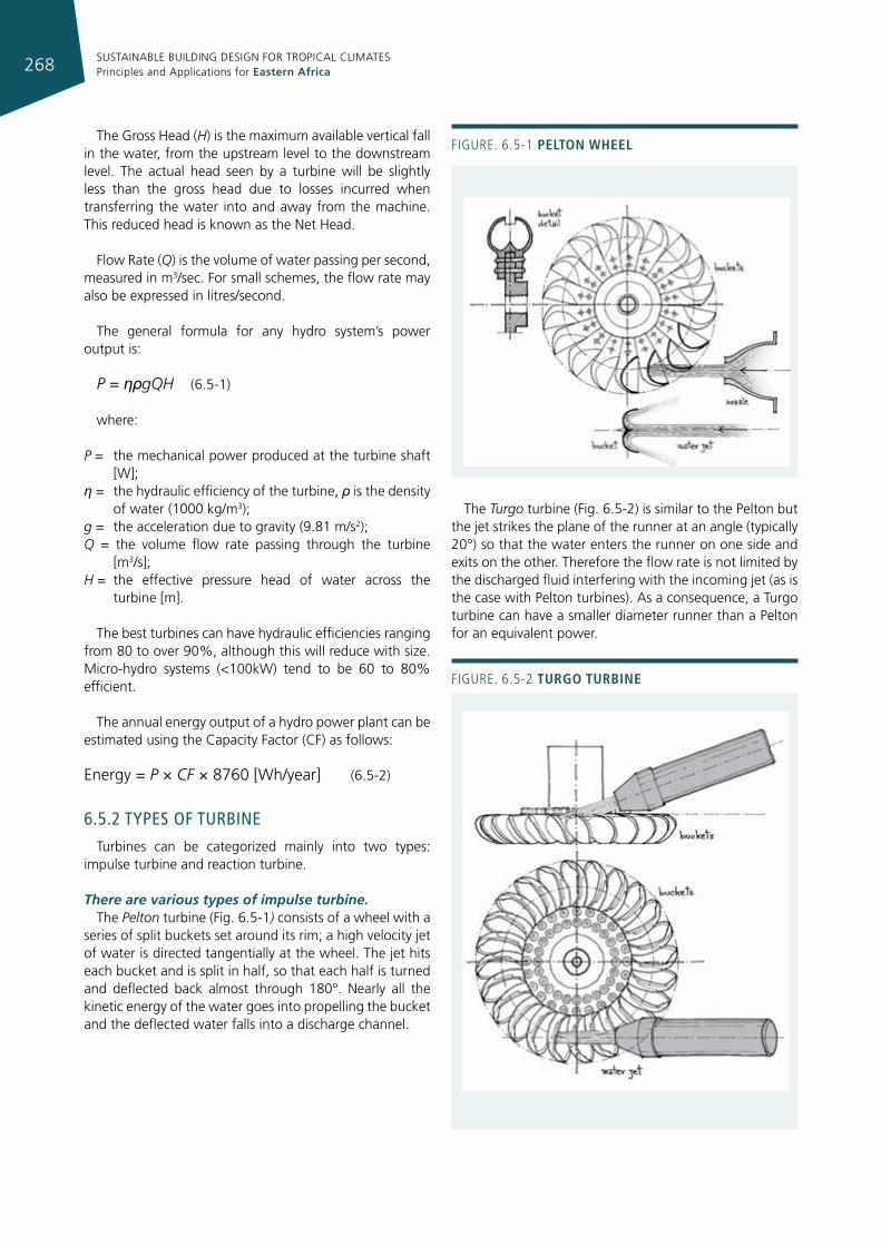
SUSTAINABLE BUILDING DESIGN FOR TROPICAL CLIMATES Principles and Applications for Eastern Africa268
The Gross Head (H) is the maximum available vertical fall in the water, from the upstream level to the downstream level. The actual head seen by a turbine will be slightly less than the gross head due to losses incurred when transferring the water into and away from the machine. This reduced head is known as the Net Head.
Flow Rate (Q) is the volume of water passing per second, measured in m3/sec. For small schemes, the flow rate may also be expressed in litres/second.
The general formula for any hydro system’s power output is:
P = ηρgQH (6.5-1)
where:
P = the mechanical power produced at the turbine shaft [W];
η = the hydraulic efficiency of the turbine, ρ is the density of water (1000 kg/m3);
g = the acceleration due to gravity (9.81 m/s2);Q = the volume flow rate passing through the turbine
[m3/s];H = the effective pressure head of water across the
turbine [m].
The best turbines can have hydraulic efficiencies ranging from 80 to over 90%, although this will reduce with size. Micro-hydro systems (<100kW) tend to be 60 to 80% efficient.
The annual energy output of a hydro power plant can be estimated using the Capacity Factor (CF) as follows:
Energy = P × CF × 8760 [Wh/year] (6.5-2)
6.5.2 Types of TurbIne
Turbines can be categorized mainly into two types: impulse turbine and reaction turbine.
There are various types of impulse turbine.The Pelton turbine (Fig. 6.5-1) consists of a wheel with a
series of split buckets set around its rim; a high velocity jet of water is directed tangentially at the wheel. The jet hits each bucket and is split in half, so that each half is turned and deflected back almost through 180°. Nearly all the kinetic energy of the water goes into propelling the bucket and the deflected water falls into a discharge channel.
The Turgo turbine (Fig. 6.5-2) is similar to the Pelton but the jet strikes the plane of the runner at an angle (typically 20°) so that the water enters the runner on one side and exits on the other. Therefore the flow rate is not limited by the discharged fluid interfering with the incoming jet (as is the case with Pelton turbines). As a consequence, a Turgo turbine can have a smaller diameter runner than a Pelton for an equivalent power.
Figure. 6.5-2 turgo turbIne
Figure. 6.5-1 pelton Wheel
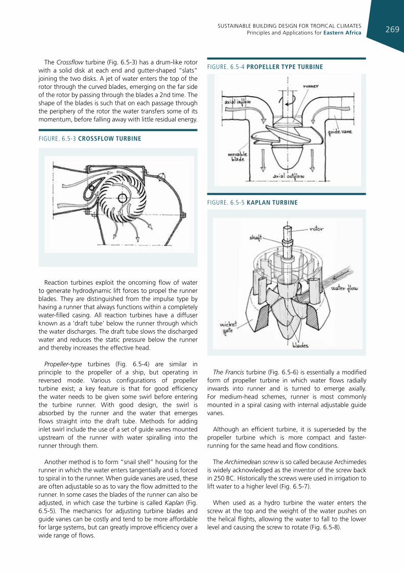
SUSTAINABLE BUILDING DESIGN FOR TROPICAL CLIMATES Principles and Applications for Eastern Africa 269
The Crossflow turbine (Fig. 6.5-3) has a drum-like rotor with a solid disk at each end and gutter-shaped “slats” joining the two disks. A jet of water enters the top of the rotor through the curved blades, emerging on the far side of the rotor by passing through the blades a 2nd time. The shape of the blades is such that on each passage through the periphery of the rotor the water transfers some of its momentum, before falling away with little residual energy.
Reaction turbines exploit the oncoming flow of water to generate hydrodynamic lift forces to propel the runner blades. They are distinguished from the impulse type by having a runner that always functions within a completely water-filled casing. All reaction turbines have a diffuser known as a ‘draft tube’ below the runner through which the water discharges. The draft tube slows the discharged water and reduces the static pressure below the runner and thereby increases the effective head.
Propeller-type turbines (Fig. 6.5-4) are similar in principle to the propeller of a ship, but operating in reversed mode. Various configurations of propeller turbine exist; a key feature is that for good efficiency the water needs to be given some swirl before entering the turbine runner. With good design, the swirl is absorbed by the runner and the water that emerges flows straight into the draft tube. Methods for adding inlet swirl include the use of a set of guide vanes mounted upstream of the runner with water spiralling into the runner through them.
Another method is to form “snail shell” housing for the runner in which the water enters tangentially and is forced to spiral in to the runner. When guide vanes are used, these are often adjustable so as to vary the flow admitted to the runner. In some cases the blades of the runner can also be adjusted, in which case the turbine is called Kaplan (Fig. 6.5-5). The mechanics for adjusting turbine blades and guide vanes can be costly and tend to be more affordable for large systems, but can greatly improve efficiency over a wide range of flows.
The Francis turbine (Fig. 6.5-6) is essentially a modified form of propeller turbine in which water flows radially inwards into runner and is turned to emerge axially. For medium-head schemes, runner is most commonly mounted in a spiral casing with internal adjustable guide vanes.
Although an efficient turbine, it is superseded by the propeller turbine which is more compact and faster-running for the same head and flow conditions.
The Archimedean screw is so called because Archimedes is widely acknowledged as the inventor of the screw back in 250 BC. Historically the screws were used in irrigation to lift water to a higher level (Fig. 6.5-7).
When used as a hydro turbine the water enters the screw at the top and the weight of the water pushes on the helical flights, allowing the water to fall to the lower level and causing the screw to rotate (Fig. 6.5-8).
Figure. 6.5-3 crossfloW turbIne
Figure. 6.5-4 propeller type turbIne
Figure. 6.5-5 kaplan turbIne
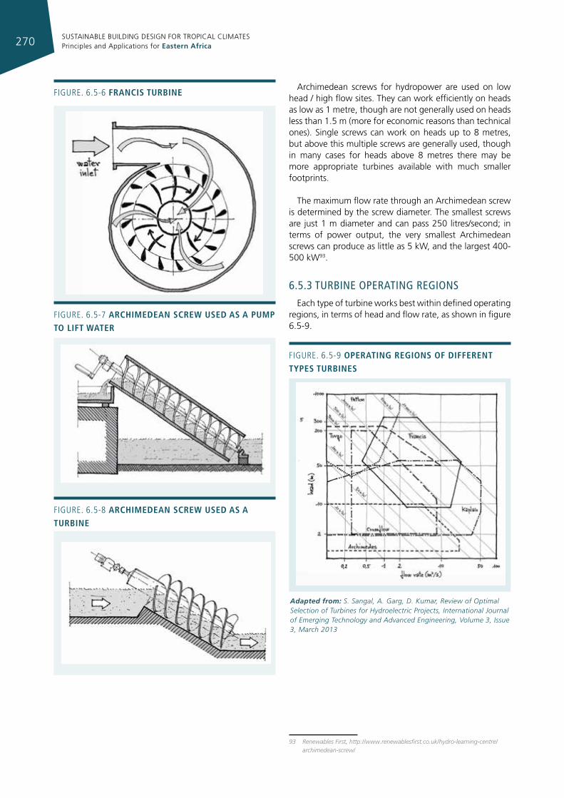
SUSTAINABLE BUILDING DESIGN FOR TROPICAL CLIMATES Principles and Applications for Eastern Africa270
Figure. 6.5-6 francIs turbIne
Figure. 6.5-7 archImedean screW used as a pump to lIft Water
Figure. 6.5-8 archImedean screW used as a turbIne
Figure. 6.5-9 operatIng regIons of dIfferent types turbInes
Adapted from: S. Sangal, A. Garg, D. Kumar, Review of Optimal Selection of Turbines for Hydroelectric Projects, International Journal of Emerging Technology and Advanced Engineering, Volume 3, Issue 3, March 2013
Archimedean screws for hydropower are used on low head / high flow sites. They can work efficiently on heads as low as 1 metre, though are not generally used on heads less than 1.5 m (more for economic reasons than technical ones). Single screws can work on heads up to 8 metres, but above this multiple screws are generally used, though in many cases for heads above 8 metres there may be more appropriate turbines available with much smaller footprints.
The maximum flow rate through an Archimedean screw is determined by the screw diameter. The smallest screws are just 1 m diameter and can pass 250 litres/second; in terms of power output, the very smallest Archimedean screws can produce as little as 5 kW, and the largest 400-500 kW93.
6.5.3 TurbIne operaTIng regIons
Each type of turbine works best within defined operating regions, in terms of head and flow rate, as shown in figure 6.5-9.
93 Renewables First, http://www.renewablesfirst.co.uk/hydro-learning-centre/archimedean-screw/
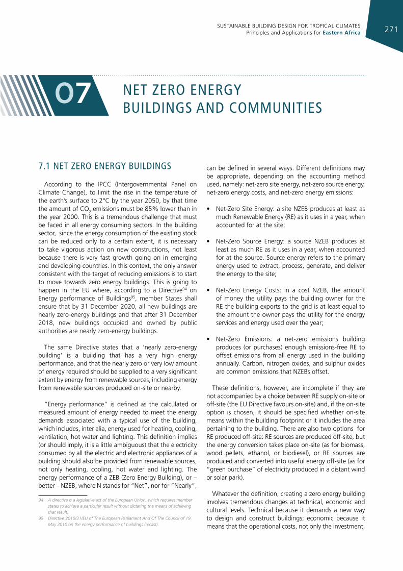
SUSTAINABLE BUILDING DESIGN FOR TROPICAL CLIMATES Principles and Applications for Eastern Africa 271
neT Zero energy buIldIngs and communITIes
07
7.1 neT Zero energy buIldIngs
According to the IPCC (Intergovernmental Panel on Climate Change), to limit the rise in the temperature of the earth’s surface to 2°C by the year 2050, by that time the amount of CO2 emissions must be 85% lower than in the year 2000. This is a tremendous challenge that must be faced in all energy consuming sectors. In the building sector, since the energy consumption of the existing stock can be reduced only to a certain extent, it is necessary to take vigorous action on new constructions, not least because there is very fast growth going on in emerging and developing countries. In this context, the only answer consistent with the target of reducing emissions is to start to move towards zero energy buildings. This is going to happen in the EU where, according to a Directive94 on Energy performance of Buildings95, member States shall ensure that by 31 December 2020, all new buildings are nearly zero-energy buildings and that after 31 December 2018, new buildings occupied and owned by public authorities are nearly zero-energy buildings.
The same Directive states that a ‘nearly zero-energy building’ is a building that has a very high energy performance, and that the nearly zero or very low amount of energy required should be supplied to a very significant extent by energy from renewable sources, including energy from renewable sources produced on-site or nearby.
“Energy performance” is defined as the calculated or measured amount of energy needed to meet the energy demands associated with a typical use of the building, which includes, inter alia, energy used for heating, cooling, ventilation, hot water and lighting. This definition implies (or should imply, it is a little ambiguous) that the electricity consumed by all the electric and electronic appliances of a building should also be provided from renewable sources, not only heating, cooling, hot water and lighting. The energy performance of a ZEB (Zero Energy Building), or – better – NZEB, where N stands for “Net”, nor for “Nearly”,
94 A directive is a legislative act of the European Union, which requires member states to achieve a particular result without dictating the means of achieving that result.
95 Directive 2010/31/EU of The European Parliament And Of The Council of 19 May 2010 on the energy performance of buildings (recast).
can be defined in several ways. Different definitions may be appropriate, depending on the accounting method used, namely: net-zero site energy, net-zero source energy, net-zero energy costs, and net-zero energy emissions:
• Net-Zero Site Energy: a site NZEB produces at least as much Renewable Energy (RE) as it uses in a year, when accounted for at the site;
• Net-Zero Source Energy: a source NZEB produces at least as much RE as it uses in a year, when accounted for at the source. Source energy refers to the primary energy used to extract, process, generate, and deliver the energy to the site;
• Net-Zero Energy Costs: in a cost NZEB, the amount of money the utility pays the building owner for the RE the building exports to the grid is at least equal to the amount the owner pays the utility for the energy services and energy used over the year;
• Net-Zero Emissions: a net-zero emissions building produces (or purchases) enough emissions-free RE to offset emissions from all energy used in the building annually. Carbon, nitrogen oxides, and sulphur oxides are common emissions that NZEBs offset.
These definitions, however, are incomplete if they are not accompanied by a choice between RE supply on-site or off-site (the EU Directive favours on-site) and, if the on-site option is chosen, it should be specified whether on-site means within the building footprint or it includes the area pertaining to the building. There are also two options for RE produced off-site: RE sources are produced off-site, but the energy conversion takes place on-site (as for biomass, wood pellets, ethanol, or biodiesel), or RE sources are produced and converted into useful energy off-site (as for “green purchase” of electricity produced in a distant wind or solar park).
Whatever the definition, creating a zero energy building involves tremendous changes at technical, economic and cultural levels. Technical because it demands a new way to design and construct buildings; economic because it means that the operational costs, not only the investment,
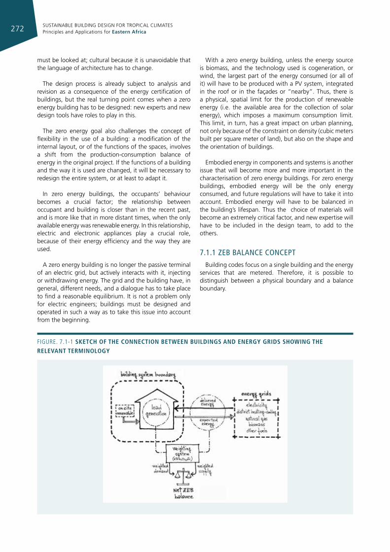
SUSTAINABLE BUILDING DESIGN FOR TROPICAL CLIMATES Principles and Applications for Eastern Africa272
must be looked at; cultural because it is unavoidable that the language of architecture has to change.
The design process is already subject to analysis and revision as a consequence of the energy certification of buildings, but the real turning point comes when a zero energy building has to be designed: new experts and new design tools have roles to play in this.
The zero energy goal also challenges the concept of flexibility in the use of a building: a modification of the internal layout, or of the functions of the spaces, involves a shift from the production-consumption balance of energy in the original project. If the functions of a building and the way it is used are changed, it will be necessary to redesign the entire system, or at least to adapt it.
In zero energy buildings, the occupants’ behaviour becomes a crucial factor; the relationship between occupant and building is closer than in the recent past, and is more like that in more distant times, when the only available energy was renewable energy. In this relationship, electric and electronic appliances play a crucial role, because of their energy efficiency and the way they are used.
A zero energy building is no longer the passive terminal of an electric grid, but actively interacts with it, injecting or withdrawing energy. The grid and the building have, in general, different needs, and a dialogue has to take place to find a reasonable equilibrium. It is not a problem only for electric engineers; buildings must be designed and operated in such a way as to take this issue into account from the beginning.
With a zero energy building, unless the energy source is biomass, and the technology used is cogeneration, or wind, the largest part of the energy consumed (or all of it) will have to be produced with a PV system, integrated in the roof or in the façades or “nearby”. Thus, there is a physical, spatial limit for the production of renewable energy (i.e. the available area for the collection of solar energy), which imposes a maximum consumption limit. This limit, in turn, has a great impact on urban planning, not only because of the constraint on density (cubic meters built per square meter of land), but also on the shape and the orientation of buildings.
Embodied energy in components and systems is another issue that will become more and more important in the characterisation of zero energy buildings. For zero energy buildings, embodied energy will be the only energy consumed, and future regulations will have to take it into account. Embodied energy will have to be balanced in the building’s lifespan. Thus the choice of materials will become an extremely critical factor, and new expertise will have to be included in the design team, to add to the others.
7.1.1 Zeb balance concepT
Building codes focus on a single building and the energy services that are metered. Therefore, it is possible to distinguish between a physical boundary and a balance boundary.
Figure. 7.1-1 sketch of the connectIon betWeen buIldIngs and energy grIds shoWIng the relevant termInology
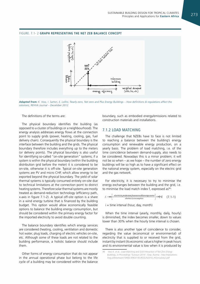
SUSTAINABLE BUILDING DESIGN FOR TROPICAL CLIMATES Principles and Applications for Eastern Africa 273
The definitions of the terms are:
The physical boundary identifies the building (as opposed to a cluster of buildings or a neighbourhood). The energy analysis addresses energy flows at the connection point to supply grids (power, heating, cooling, gas, fuel delivery chain). Consequently the physical boundary is the interface between the building and the grids. The physical boundary therefore includes everything up to the meters (or delivery points). The physical boundary is also useful for identifying so-called “on-site generation” systems; if a system is within the physical boundary (within the building distribution grid before the meter) it is considered to be on-site, otherwise it is off-site. Typical on-site generation systems are PV and micro CHP, which allow energy to be exported beyond the physical boundary. The yield of solar thermal systems is typically consumed entirely on-site due to technical limitations at the connection point to district heating systems. Therefore solar thermal systems are mostly treated as demand-reduction technology (efficiency path, x-axis in figure 7.1-2). A typical off-site option is a share in a wind energy turbine that is financed by the building budget. This option would allow economically feasible options to balance the building energy consumption, but should be considered within the primary energy factor for the imported electricity to avoid double counting.
The balance boundary identifies which energy services are considered (heating, cooling, ventilation and domestic hot water, plug loads, charging of electric vehicles on-site, etc. Although some of these loads are not related to the building performance, a holistic balance should include them.
Other forms of energy consumption that do not appear in the annual operational phase but belong to the life cycle of a building may be considered within the balance
boundary, such as embodied energy/emissions related to construction materials and installations.
7.1.2 load maTchIng
The challenge that NZEBs have to face is not limited to reaching a balance between the building’s energy consumption and renewable energy production, on a yearly basis. The problem of load matching, i.e. of the time coincidence between demand-supply, also needs to be considered. Nowadays this is a minor problem; it will not be so when – as we hope – the number of zero energy buildings will be so high as to have a significant effect on the national energy system, especially on the electric grid and the gas network.
For electricity, it is necessary to try to minimise the energy exchanges between the building and the grid, i.e. to minimise the load match index f, expressed as96:
(7.1-1)
i = time interval (hour, day, month)
When the time interval (yearly, monthly, daily, hourly) is diminished, the index becomes smaller, down to values lower than 30% when the hourly time interval is chosen.
There is also another type of coincidence to consider, regarding the value (economical or environmental) of electricity that is supplied to or received from the grid, instant by instant (its economic value is higher in peak hours and its environmental value is low when it is produced by
96 Voss K. et al., Load Matching and Grid Interaction of Net Zero Energy Buildings, in Proceedings “Eurosun 2010”, Graz, Austria - http://repositorio.lneg.pt/bitstream/10400.9/963/1/EUROSUN2010_HGoncalves2.pdf
Figure. 7.1- 2 graph representIng the net zeb balance concept
Adapted from: K. Voss, I. Sartori, E. Lollini, Nearly-zero, Net zero and Plus Energy Buildings – How definitions & regulations affect the solutions, REHVA Journal – December 2012
SUSTAINABLE BUILDING DESIGN FOR TROPICAL CLIMATES Principles and Applications for Eastern Africa274
Building system boundary The boundary at which to compare energy flows flowing in and out the system. it includes:
Physical boundary: can encompass a single building or a group of buildings; determines whether renewable resources are ‘on-site’ or ‘off-site’;
Balance boundary: determines which energy uses (e.g. heating, cooling, ventilation, hot water, lighting, appliances) are included in the balance.
energy grids (or simply ‘grids’) The supply system of energy carriers such as electricity, natural gas, thermal networks for district cooling, biomass and other fuels. A grid may be a two-way grid, delivering energy to a building and occasionally receiving energy back from it. This is normally the case for electricity grid and thermal networks.
Delivered energy energy flowing from the grids to buildings, specified per each energy carrier in [kWh/y] or [kWh/m2y]. This is the energy imported by the building. However, it is established practice in many countries to name this quantity ‘delivered energy’.
exported energy energy flowing from buildings to the grid, specified per each energy carrier in [kWh/y] or [kWh/m2y].
Load Building’s energy demand, specified per each energy carrier in [kWh/y] or [kWh/m2 y]. The load may not coincide with delivered energy due to self-consumption of energy generated on-site.
generation Building’s energy generation, specified per each energy carrier in [kWh/y] or [kWh/m2 y]. The generation may not coincide with exported energy due to self-consumption of energy generated on site.
Weighting system A weighting system converts the physical units into other metrics, for example accounting for the energy used (or emissions released) to extract, generate, and deliver the energy. Weighting factors may also reflect political preferences rather than purely scientific or engineering considerations.
Weighted demand The sum of all delivered energy (or load), obtained by adding together all energy carriers each multiplied by its respective weighting factor.
Weighted supply The sum of all exported energy (or generation), obtained by adding together all energy carriers each multiplied by its respective weighting factor.
Net ZeB balance A condition that is satisfied when weighted supply meets or exceeds weighted demand over a period of time, nominally a year. The net zero energy balance can be determined either from the balance between delivered and exported energy or between load and generation. The former is called import/export balance and the latter load/generation balance. A third option is possible, using monthly net values of load and generation and it is called monthly net balance.
The Net ZeB balance is calculated as:
NetZeB balance : |weighted supply|−|weighted demand| = 0
where absolute values are used simply to avoid confusion over whether supply or demand is considered as positive. The Net ZeB balance can be represented graphically as in figure 7.1-2, plotting the weighted demand on the x-axis and the weighted supply on the y-axis.
TABLe 7.1-1 gIves an overvIeW of relevant termInology addressIng energy use In buIldIngs and the connectIon betWeen buIldIngs and energy grIds.
Adapted from: K. Voss, I. Sartori, E. Lollini, Nearly-zero, Net zero and Plus Energy Buildings – How definitions & regulations affect the solutions, REHVA Journal – December 2012
a fuel mix that – at that moment – is generating more CO2 per kWh than the average). The ideal is that a ZEB should not only minimise the load match index, but should also supply energy to or absorb it from the grid at the time that is most convenient (economically or environmentally).
In a ZEB some form of electricity storage (physical or virtual) has to be provided. Physical storage could be thermal , which is already used for both heating and cooling. Or it could be the storage of the energy that can be obtained by the integration of non-predictable energy production systems, like solar and wind, with systems that
can be modulated according to the needs, such as gas or biomass CHP. In the case of gas, the fossil primary energy consumed can be balanced with the surplus production from the renewable energy system.
Virtual storage is that obtainable by means of sophisticated control systems, enabling the operation (on/off) of the electrical appliances and of the HVAC system, according to the weather, the needs of the grid, instantaneous kWh cost, etc., minimising the supply-demand mismatch as much as possible.
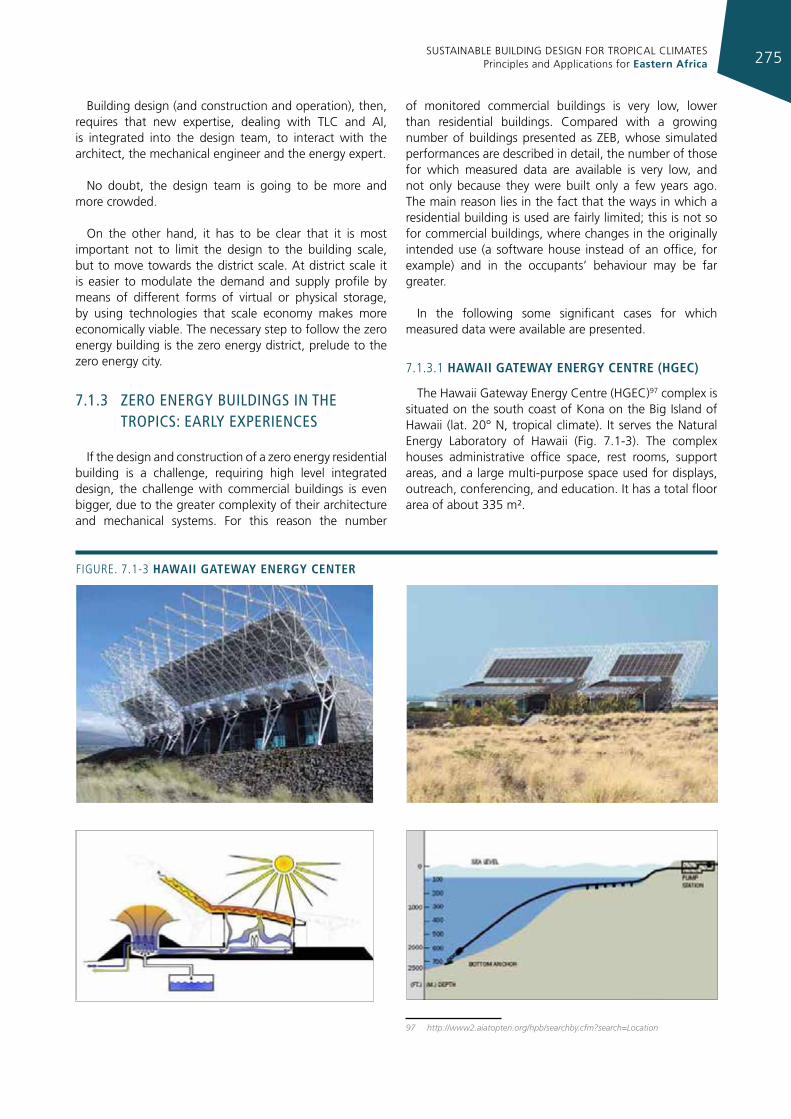
SUSTAINABLE BUILDING DESIGN FOR TROPICAL CLIMATES Principles and Applications for Eastern Africa 275
Building design (and construction and operation), then, requires that new expertise, dealing with TLC and AI, is integrated into the design team, to interact with the architect, the mechanical engineer and the energy expert.
No doubt, the design team is going to be more and more crowded.
On the other hand, it has to be clear that it is most important not to limit the design to the building scale, but to move towards the district scale. At district scale it is easier to modulate the demand and supply profile by means of different forms of virtual or physical storage, by using technologies that scale economy makes more economically viable. The necessary step to follow the zero energy building is the zero energy district, prelude to the zero energy city.
7.1.3 Zero energy buIldIngs In The TropIcs: early experIences
If the design and construction of a zero energy residential building is a challenge, requiring high level integrated design, the challenge with commercial buildings is even bigger, due to the greater complexity of their architecture and mechanical systems. For this reason the number
of monitored commercial buildings is very low, lower than residential buildings. Compared with a growing number of buildings presented as ZEB, whose simulated performances are described in detail, the number of those for which measured data are available is very low, and not only because they were built only a few years ago. The main reason lies in the fact that the ways in which a residential building is used are fairly limited; this is not so for commercial buildings, where changes in the originally intended use (a software house instead of an office, for example) and in the occupants’ behaviour may be far greater.
In the following some significant cases for which measured data were available are presented.
7.1.3.1 haWaII gateWay energy centre (hgec)
The Hawaii Gateway Energy Centre (HGEC)97 complex is situated on the south coast of Kona on the Big Island of Hawaii (lat. 20° N, tropical climate). It serves the Natural Energy Laboratory of Hawaii (Fig. 7.1-3). The complex houses administrative office space, rest rooms, support areas, and a large multi-purpose space used for displays, outreach, conferencing, and education. It has a total floor area of about 335 m².
97 http://www2.aiatopten.org/hpb/searchby.cfm?search=Location
Figure. 7.1-3 haWaII gateWay energy center
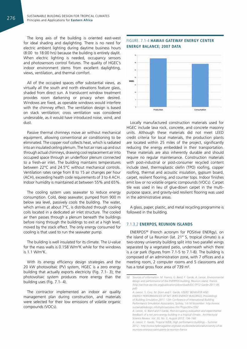
SUSTAINABLE BUILDING DESIGN FOR TROPICAL CLIMATES Principles and Applications for Eastern Africa276
The long axis of the building is oriented east-west for ideal shading and daylighting. There is no need for electric ambient lighting during daytime business hours (8:00 to 18:00 hrs) because the building is entirely daylit. When electric lighting is needed, occupancy sensors and photosensors control fixtures. The quality of HGEC’s indoor environment stems from excellent daylighting, views, ventilation, and thermal comfort.
All of the occupied spaces offer substantial views, as virtually all the south and north elevations feature glass, shaded from direct sun. A translucent window treatment provides room darkening or privacy when desired. Windows are fixed, as operable windows would interfere with the chimney effect. The ventilation design is based on stack ventilation; cross ventilation was considered undesirable, as it would have introduced noise, wind, and dust.
Passive thermal chimneys move air without mechanical equipment, allowing conventional air conditioning to be eliminated. The copper roof collects heat, which is radiated into an insulated ceiling plenum. The hot air rises up and out through actual chimneys, drawing cool replacement air into occupied space through an underfloor plenum connected to a fresh-air inlet. The building maintains temperatures between 22°C and 24.5°C without mechanical controls. Ventilation rates range from 8 to 15 air changes per hour (ACH), exceeding health code requirements of 3 to 4 ACH. Indoor humidity is maintained at between 55% and 65%.
The cooling system uses seawater to reduce energy consumption. Cold, deep seawater, pumped from 900 m below sea level, passively cools the building. The water, which arrives at about 7°C, is distributed through cooling coils located in a dedicated air inlet structure. The cooled air then passes through a plenum beneath the buildings before rising through the buildings to exit at a high level, moved by the stack effect. The only energy consumed for cooling is that used to run the seawater pump.
The building is well insulated for its climate. The U-value for the mass walls is 0.158 W/m2K while for the windows is 1.1 W/m2K.
With its energy efficiency design strategies and the 20 kW photovoltaic (PV) system, HGEC is a zero energy building that actually exports electricity (Fig. 7.1- 3); the photovoltaic system produces more energy than the building uses (Fig. 7.1- 4).
The contractor implemented an indoor air quality management plan during construction, and materials were selected for their low emissions of volatile organic compounds (VOCs).
Locally manufactured construction materials used for HGEC include lava rock, concrete, and concrete masonry units. Although these materials did not meet LEED credit criteria for local materials, the production plants are located within 25 miles of the project, significantly reducing the energy embedded in their transportation. These materials are also inherently durable and should require no regular maintenance. Construction materials with post-industrial or post-consumer recycled content include steel, thermoplastic olefin (TPO) roofing, copper roofing, thermal and acoustic insulation, gypsum board, carpet, resilient flooring, and counter tops. Indoor finishes emit low or no volatile organic compounds (VOCs). Carpet tile was used in lieu of glue-down carpet in the multi-purpose space, and gravity-laid resilient flooring was used in the administrative areas.
A glass, paper, plastic, and metal recycling programme is followed in the building.
7.1.3.2 enerpos, reunIon Islands
ENERPOS98 (French acronym for POSitive ENERgy), on the island of La Reunion (lat. 21° S, tropical climate) is a two-storey university building split into two parallel wings separated by a vegetated patio, underneath which there is a car park (figures from 7.1-5 to 7.1-8). The building is composed of an administration zone, with 7 offices and a meeting room, 2 computer rooms and 5 classrooms and has a total gross floor area of 739 m².
98 Sources of information: M. Franco, G. Baird, F. Garde, A. Lenoir, Environmental design and performance of the ENERPOS building, Reunion island, France. (http://archive.iea-shc.org/publications/downloads/DC-TP12-Garde-2011-06.pdf)
A. Lenoir, S. Cory, M. Donn and F. Garde, USERS’ BEHAVIOR AND ENERGY PERFORMANCES OF NET ZERO ENERGY BUILDINGS,.Proceedings of Building Simulation 2011: 12th Conference of International Building Performance Simulation Association, Sydney, 14-16 November. http://www.sustainabledesign.info/hpb/overview.cfm?ProjectID=1592
A. Lenoir, G. Baird and F.Garde, Post-occupancy evaluation and experimental feedback of a net zero-energy building in a tropical climate.. Architectural Science Review. Vol. 55, No. 3, August 2012, 156–168
A. Lenoir, F. Garde, Tropical NZEB, High performance buildings – Summer 2012 - http://www.hpbmagazine.org/case-studies/educational/university-of-la-reunions-enerpos-saint-pierre-la-reunion-france
Figure. 7.1-4 haWaII gateWay energy center energy balance; 2007 data
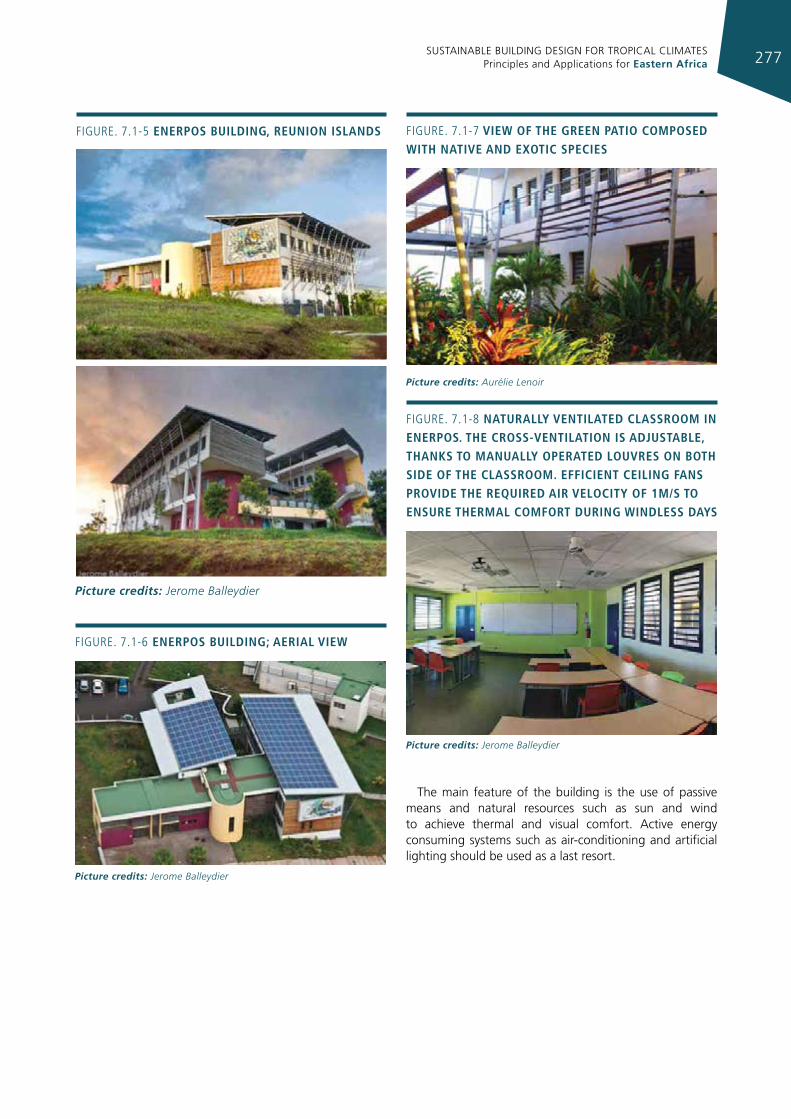
SUSTAINABLE BUILDING DESIGN FOR TROPICAL CLIMATES Principles and Applications for Eastern Africa 277
Figure. 7.1-5 enerpos buIldIng, reunIon Islands
Picture credits: Jerome Balleydier
Figure. 7.1-7 vIeW of the green patIo composed WIth natIve and exotIc specIes
Picture credits: Aurélie Lenoir
Figure. 7.1-8 naturally ventIlated classroom In enerpos. the cross-ventIlatIon Is adjustable, thanks to manually operated louvres on both sIde of the classroom. effIcIent ceIlIng fans provIde the requIred aIr velocIty of 1m/s to ensure thermal comfort durIng WIndless days
Picture credits: Jerome Balleydier
Figure. 7.1-6 enerpos buIldIng; aerIal vIeW
Picture credits: Jerome Balleydier
The main feature of the building is the use of passive means and natural resources such as sun and wind to achieve thermal and visual comfort. Active energy consuming systems such as air-conditioning and artificial lighting should be used as a last resort.
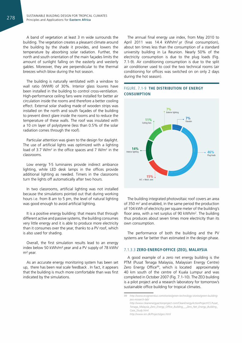
SUSTAINABLE BUILDING DESIGN FOR TROPICAL CLIMATES Principles and Applications for Eastern Africa278
A band of vegetation at least 3 m wide surrounds the building. The vegetation creates a pleasant climate around the building by the shade it provides, and lowers the temperature by absorbing solar radiation. Further, the north and south orientation of the main façades limits the amount of sunlight falling on the easterly and westerly gables. Moreover, they are perpendicular to the thermal breezes which blow during the hot season.
The building is naturally ventilated with a window to wall ratio (WWR) of 30%. Interior glass louvres have been installed in the building to control cross-ventilation. High-performance ceiling fans were installed for better air circulation inside the rooms and therefore a better cooling effect. External solar shading made of wooden strips was installed on the north and south façades of the building to prevent direct glare inside the rooms and to reduce the temperature of these walls. The roof was insulated with a 10 cm layer of polystyrene (less than 0.5% of the solar radiation comes through the roof).
Particular attention was given to the design for daylight. The use of artificial lights was optimized with a lighting load of 3.7 W/m2 in the office spaces and 7 W/m2 in the classrooms.
Low energy T-5 luminaires provide indirect ambiance lighting, while LED desk lamps in the offices provide additional lighting as needed. Timers in the classrooms turn the lights off automatically after two hours.
In two classrooms, artificial lighting was not installed because the simulations pointed out that during working hours i.e. from 8 am to 5 pm, the level of natural lighting was good enough to avoid artificial lighting.
It is a positive energy building: that means that through different active and passive systems, the building consumes very little energy and it is able to produce more electricity than it consumes over the year, thanks to a PV roof, which is also used for shading.
Overall, the first simulation results lead to an energy index below 50 kWh/m².year and a PV supply of 78 kWh/m².year.
As an accurate energy monitoring system has been set up, there has been real scale feedback . In fact, it appears that the building is much more comfortable than was first indicated by the simulations.
The annual final energy use index, from May 2010 to April 2011 was 14.4 kWh/m2.yr (final consumption), about ten times less than the consumption of a standard university building in La Reunion. Nearly 50% of the electricity consumption is due to the plug loads (Fig. 7.1-9). Air conditioning consumption is due to the split air conditioner used to cool the two technical rooms (air conditioning for offices was switched on on only 2 days during the hot season).
The building integrated photovoltaic roof covers an area of 350 m2 and enabled, in the same period the production of 104 kWh of electricity per square meter of the building’s floor area, with a net surplus of 90 kWh/m2. The building thus produces about seven times more electricity than its own consumption.
The performance of both the building and the PV systems are far better than estimated in the design phase.
7.1.3.3 zero-energy-offIce (zeo), malaysIa
A good example of a zero net energy building is the PTM (Pusat Tenaga Malaysia, Malaysian Energy Centre) Zero Energy Office99, which is located approximately 40 km south of the centre of Kuala Lumpur and was completed in October 2007 (Fig. 7.1-10). The ZEO building is a pilot project and a research laboratory for tomorrow’s sustainable office building for tropical climates.
99 http://www.ecogreen4us.com/stories/green-technology-stories/green-building-zeo-research-lab/ http://www.cleanenergyactionproject.com/CleanEnergyActionProject/CS.Pusat_Tenaga_Malaysia_Zero_Energy_Office_Building___Zero_Net_Energy_Building_Case_Study.html
http://www.ien.dk/Projects/geo.html
46% Plug loads
7% Elavator
7% Exterior lighting
11%Ceiling fans
15% A/C + Mech. vent
14%Interior lighting
Figure. 7.1-9 the dIstrIbutIon of energy consumptIon
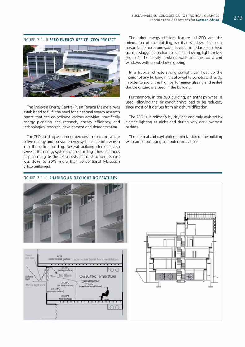
SUSTAINABLE BUILDING DESIGN FOR TROPICAL CLIMATES Principles and Applications for Eastern Africa 279
Figure. 7.1-10 zero energy offIce (zeo) project
The Malaysia Energy Centre (Pusat Tenaga Malaysia) was established to fulfil the need for a national energy research centre that can co-ordinate various activities, specifically energy planning and research, energy efficiency, and technological research, development and demonstration.
The ZEO building uses integrated design concepts where active energy and passive energy systems are interwoven into the office building. Several building elements also serve as the energy systems of the building. These methods help to mitigate the extra costs of construction (its cost was 20% to 30% more than conventional Malaysian office buildings).
The other energy efficient features of ZEO are: the orientation of the building, so that windows face only towards the north and south in order to reduce solar heat gains; a staggered section for self-shadowing; light shelves (Fig. 7.1-11); heavily insulated walls and the roofs; and windows with double low-e glazing.
In a tropical climate strong sunlight can heat up the interior of any building if it is allowed to penetrate directly. In order to avoid, this high performance glazing and sealed double glazing are used in the building.
Furthermore, in the ZEO building, an enthalpy wheel is used, allowing the air conditioning load to be reduced, since most of it derives from air dehumidification.
The ZEO is lit primarily by daylight and only assisted by electric lighting at night and during very dark overcast periods.
The thermal and daylighting optimization of the building was carried out using computer simulations.
Figure. 7.1-11 shadIng an daylIghtIng features
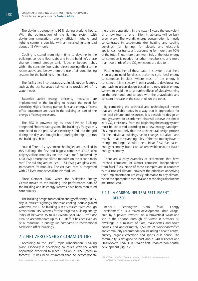
SUSTAINABLE BUILDING DESIGN FOR TROPICAL CLIMATES Principles and Applications for Eastern Africa280
The daylight autonomy is 95% during working hours. With the optimization of the lighting system with daylighting simulation, energy efficient lighting and lighting control is possible, with an installed lighting load about of 5 W/m2 only.
Cooling is stored from night time to daytime in the building’s concrete floor slabs and in the building’s phase change thermal storage tank. Tubes embedded tubes within the concrete floor slabs release cooling effect to the rooms above and below them the use of air conditioning systems for the building is minimised.
The facility also incorporates sustainable design features such as the use harvested rainwater to provide 2/3 of its water needs.
Extensive active energy efficiency measures are implemented in the building to reduce the need for electricity. High efficiency pumps, fans and energy efficient office equipment are used in the building as part of the energy efficiency measures.
The ZEO is powered by its own BIPV or Building Integrated Photovoltaic system. The building’s PV system is connected to the grid. Solar electricity is fed into the grid during the day, and bought back during the night, to run the building’s chiller.
Four different PV systems/technologies are installed in this building. The first and biggest comprises 47.28 kWp polycrystalline modules on the main roof, followed by 6.08 kWp amorphous silicon modules on the second main roof. The building atrium uses 11.64 kWp glass-glass semi-transparent PV modules. The car park roof is integrated with 27 kWp monocrystalline PV modules.
Since October 2007, when the Malaysian Energy Centre moved to the building, the performance data of the building and its energy systems have been monitored continuously.
The building design focussed on energy efficiency (100% day-lit, efficient lightings, floor slab cooling, double-glazed windows, etc.). The building is self-sufficient with enough power from BIPV systems for the targeted building energy index of between 35 to 40 kWh/m2/year (4200 m2 floor area, to accommodate up to 111 staff. It has achieved an 85% reduction in energy use compared to conventional Malaysian office buildings).
7.2 neT Zero energy communITIesAccording to the UN100, rapid urbanisation is taking
place, especially in developing countries, with the world population expected to reach 9 billion in 2050 (medium forecast). It has been estimated that, to accommodate
100 United Nations, Urban and rural areas 2003, New York, 2004
the urban population, in the next 45 years the equivalent of a new town of one million inhabitants will be built every week. The world’s energy consumption is mostly concentrated in settlements (for heating and cooling buildings, for lighting, for electric and electronic appliances, for transport), accounting for more than 70% of the total. Thus, more than two thirds of the total energy consumption is needed for urban metabolism, and more than two thirds of the CO2 emissions are due to it.
Putting together all these data, it is evident that there is an urgent need for drastic action to curb fossil energy consumption in cities, where most of the energy is consumed. It is necessary, in other words, to develop a new approach to urban design based on a new urban energy system, to avoid the catastrophic effects of global warming on the one hand, and to cope with the unavoidable and constant increase in the cost of oil on the other.
By combining the technical and technological means that are available today in a way that is appropriate for the local climate and resources, it is possible to design an energy system for a settlement that will achieve the aim of zero CO2 emissions. From the beginning the energy system must be conceived according to a new energy paradigm. This implies not only that the architectural design process for the individual buildings has to change, but also – and mainly – that the planning rules of the community have to change: no longer should it be a linear, fossil fuel based, energy economy, but a circular, renewable resource based energy economy.
There are already examples of settlements that have reached complete (or almost complete) independence from fossil fuels. None of these examples are in countries with a tropical climate, however the principles underlying their implementation are easily adaptable to any climate, when the appropriate technical and technological solutions are introduced.
7.2.1 a carbon neuTral seTTlemenT: bedZed
BedZED [Beddington ‘Zero (fossil) Energy Development]101 is a mixed development urban village, built by a private investor; on a brownfield wasteland site in the London Borough of Sutton it provides 82 dwellings in a mixture of flats, maisonettes and town houses, and approximately 2,500m² of workspace/office and community accommodation including a health centre, nursery, organic café/shop and sports club house. The community is designed to host about 240 residents and 200 workers. BedZED is Britain’s first urban carbon-neutral development (Fig. 7.2-1).
101 C. Twinn, BedZed, The Arup Journal, 1/2003, http://www.arup.com/DOWNLOADBANK/download68.pdf
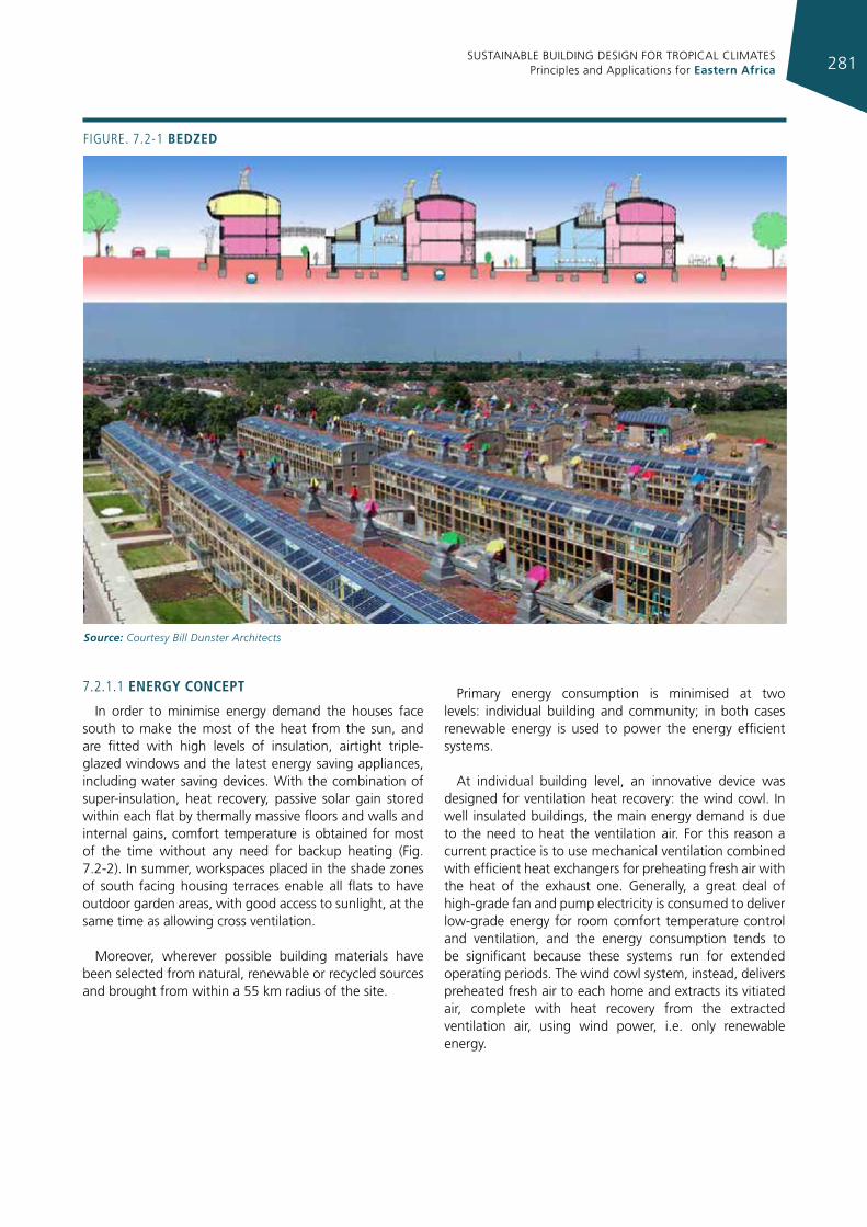
SUSTAINABLE BUILDING DESIGN FOR TROPICAL CLIMATES Principles and Applications for Eastern Africa 281
7.2.1.1 energy concept
In order to minimise energy demand the houses face south to make the most of the heat from the sun, and are fitted with high levels of insulation, airtight triple-glazed windows and the latest energy saving appliances, including water saving devices. With the combination of super-insulation, heat recovery, passive solar gain stored within each flat by thermally massive floors and walls and internal gains, comfort temperature is obtained for most of the time without any need for backup heating (Fig. 7.2-2). In summer, workspaces placed in the shade zones of south facing housing terraces enable all flats to have outdoor garden areas, with good access to sunlight, at the same time as allowing cross ventilation.
Moreover, wherever possible building materials have been selected from natural, renewable or recycled sources and brought from within a 55 km radius of the site.
Primary energy consumption is minimised at two levels: individual building and community; in both cases renewable energy is used to power the energy efficient systems.
At individual building level, an innovative device was designed for ventilation heat recovery: the wind cowl. In well insulated buildings, the main energy demand is due to the need to heat the ventilation air. For this reason a current practice is to use mechanical ventilation combined with efficient heat exchangers for preheating fresh air with the heat of the exhaust one. Generally, a great deal of high-grade fan and pump electricity is consumed to deliver low-grade energy for room comfort temperature control and ventilation, and the energy consumption tends to be significant because these systems run for extended operating periods. The wind cowl system, instead, delivers preheated fresh air to each home and extracts its vitiated air, complete with heat recovery from the extracted ventilation air, using wind power, i.e. only renewable energy.
Figure. 7.2-1 bedzed
Source: Courtesy Bill Dunster Architects
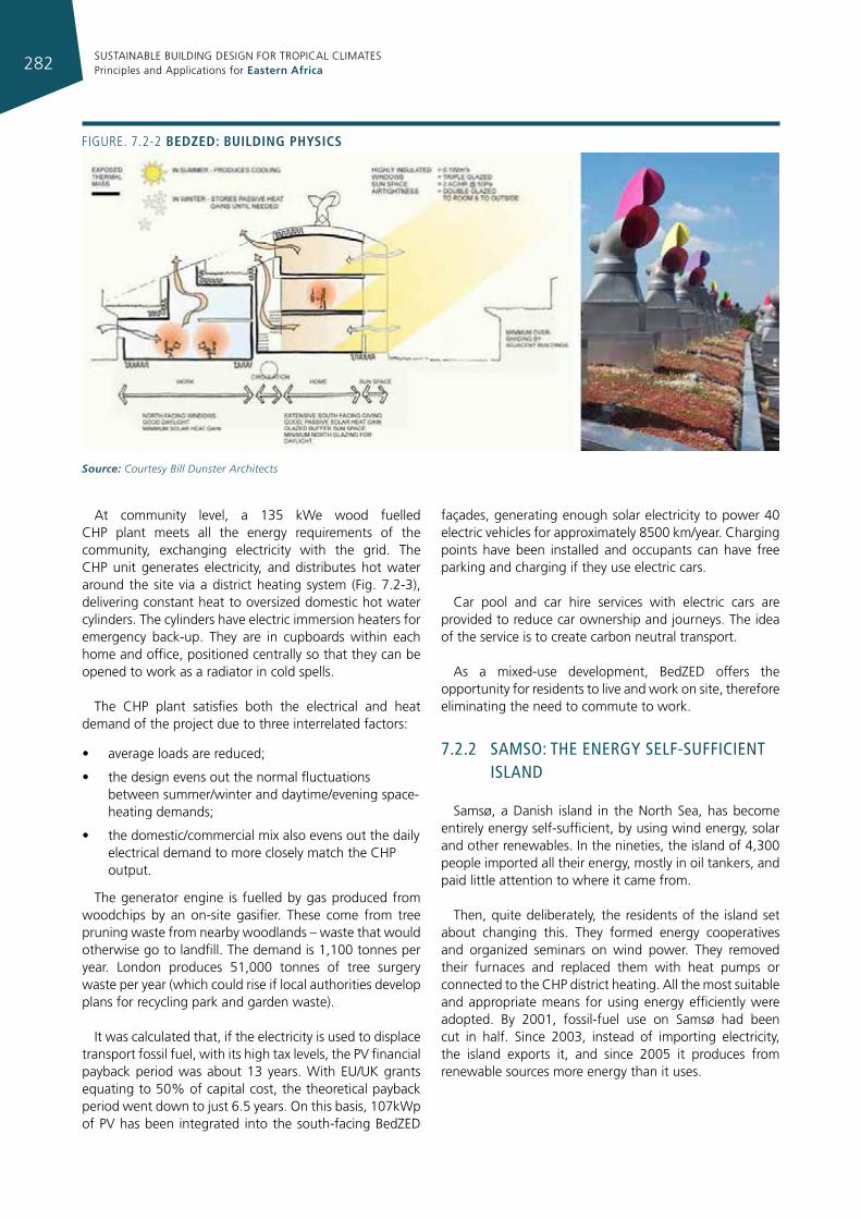
SUSTAINABLE BUILDING DESIGN FOR TROPICAL CLIMATES Principles and Applications for Eastern Africa282
Figure. 7.2-2 bedzed: buIldIng physIcs
Source: Courtesy Bill Dunster Architects
At community level, a 135 kWe wood fuelled CHP plant meets all the energy requirements of the community, exchanging electricity with the grid. The CHP unit generates electricity, and distributes hot water around the site via a district heating system (Fig. 7.2-3), delivering constant heat to oversized domestic hot water cylinders. The cylinders have electric immersion heaters for emergency back-up. They are in cupboards within each home and office, positioned centrally so that they can be opened to work as a radiator in cold spells.
The CHP plant satisfies both the electrical and heat demand of the project due to three interrelated factors:
• average loads are reduced;
• the design evens out the normal fluctuations between summer/winter and daytime/evening space-heating demands;
• the domestic/commercial mix also evens out the daily electrical demand to more closely match the CHP output.
The generator engine is fuelled by gas produced from woodchips by an on-site gasifier. These come from tree pruning waste from nearby woodlands – waste that would otherwise go to landfill. The demand is 1,100 tonnes per year. London produces 51,000 tonnes of tree surgery waste per year (which could rise if local authorities develop plans for recycling park and garden waste).
It was calculated that, if the electricity is used to displace transport fossil fuel, with its high tax levels, the PV financial payback period was about 13 years. With EU/UK grants equating to 50% of capital cost, the theoretical payback period went down to just 6.5 years. On this basis, 107kWp of PV has been integrated into the south-facing BedZED
façades, generating enough solar electricity to power 40 electric vehicles for approximately 8500 km/year. Charging points have been installed and occupants can have free parking and charging if they use electric cars.
Car pool and car hire services with electric cars are provided to reduce car ownership and journeys. The idea of the service is to create carbon neutral transport.
As a mixed-use development, BedZED offers the opportunity for residents to live and work on site, therefore eliminating the need to commute to work.
7.2.2 samso: The energy self-suffIcIenT Island
Samsø, a Danish island in the North Sea, has become entirely energy self-sufficient, by using wind energy, solar and other renewables. In the nineties, the island of 4,300 people imported all their energy, mostly in oil tankers, and paid little attention to where it came from.
Then, quite deliberately, the residents of the island set about changing this. They formed energy cooperatives and organized seminars on wind power. They removed their furnaces and replaced them with heat pumps or connected to the CHP district heating. All the most suitable and appropriate means for using energy efficiently were adopted. By 2001, fossil-fuel use on Samsø had been cut in half. Since 2003, instead of importing electricity, the island exports it, and since 2005 it produces from renewable sources more energy than it uses.
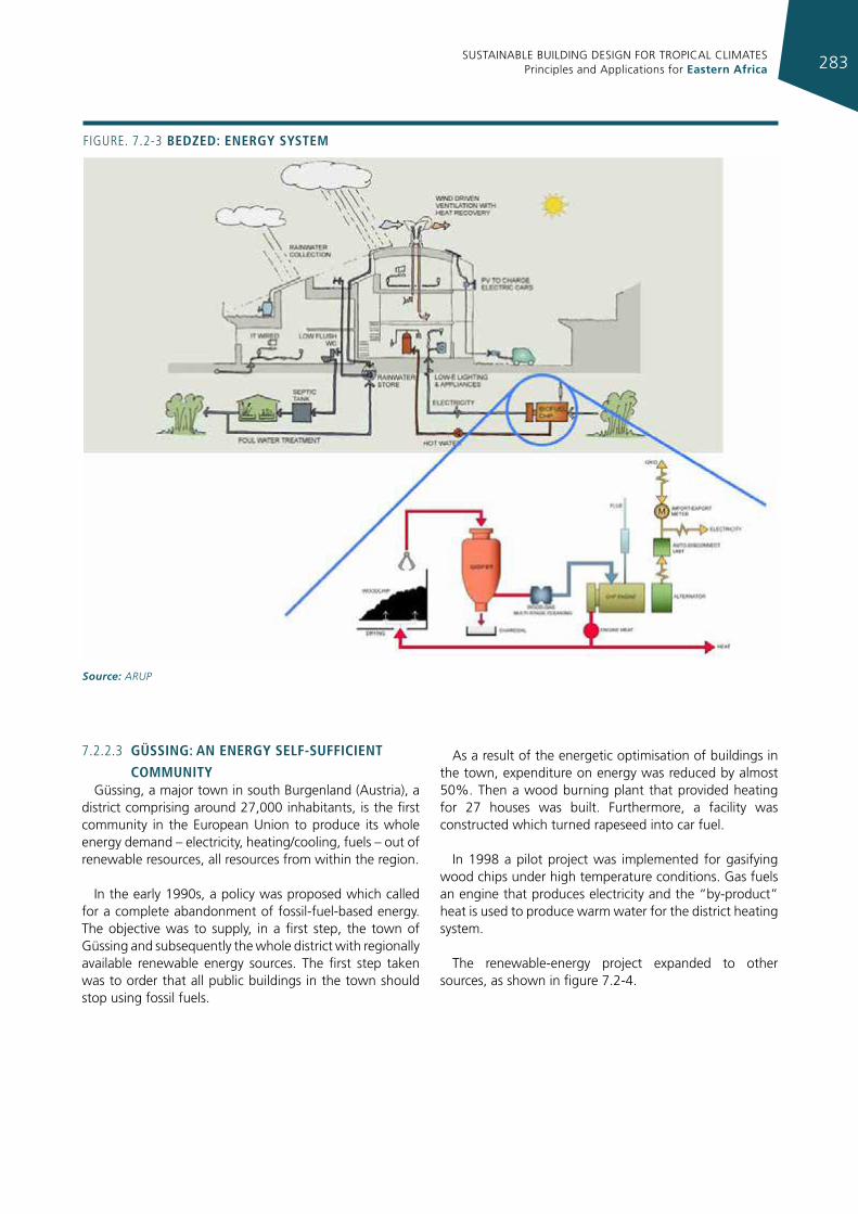
SUSTAINABLE BUILDING DESIGN FOR TROPICAL CLIMATES Principles and Applications for Eastern Africa 283
Figure. 7.2-3 bedzed: energy system
Source: ARUP
7.2.2.3 güssIng: an energy self-suffIcIent
communItyGüssing, a major town in south Burgenland (Austria), a
district comprising around 27,000 inhabitants, is the first community in the European Union to produce its whole energy demand – electricity, heating/cooling, fuels – out of renewable resources, all resources from within the region.
In the early 1990s, a policy was proposed which called for a complete abandonment of fossil-fuel-based energy. The objective was to supply, in a first step, the town of Güssing and subsequently the whole district with regionally available renewable energy sources. The first step taken was to order that all public buildings in the town should stop using fossil fuels.
As a result of the energetic optimisation of buildings in the town, expenditure on energy was reduced by almost 50%. Then a wood burning plant that provided heating for 27 houses was built. Furthermore, a facility was constructed which turned rapeseed into car fuel.
In 1998 a pilot project was implemented for gasifying wood chips under high temperature conditions. Gas fuels an engine that produces electricity and the “by-product” heat is used to produce warm water for the district heating system.
The renewable-energy project expanded to other sources, as shown in figure 7.2-4.
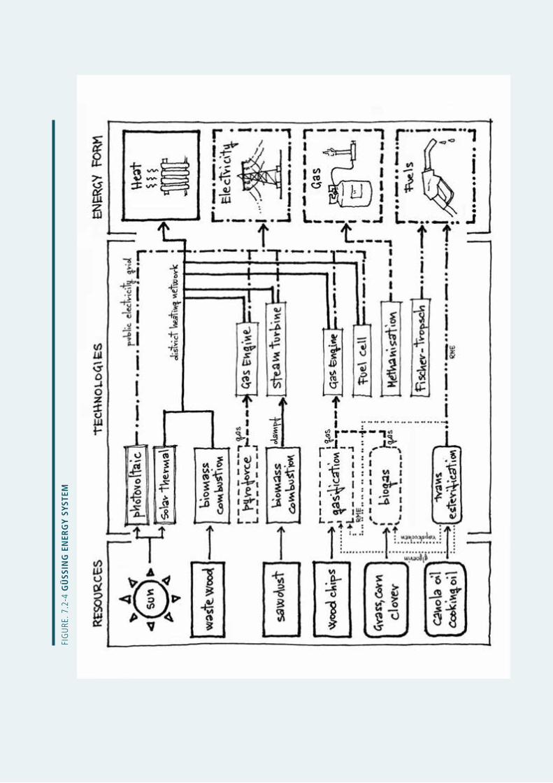
SUSTAINABLE BUILDING DESIGN FOR TROPICAL CLIMATES Principles and Applications for Eastern Africa284
Fig
ure
. 7.2
-4 g
üss
Ing
en
erg
y s
yste
m
SUSTAINABLE BUILDING DESIGN FOR TROPICAL CLIMATES Principles and Applications for Eastern Africa 285
glossary
Absolute humidity (humidity ratio) – the weight of water vapour per unit volume of dry air.
Absorber – the blackened surface in a solar collector that absorbs solar radiation and converts it to heat.
Absorptance – the ratio of the radiation absorbed by a surface to the total energy falling on that surface.
Active solar energy system – a system that requires auxiliary energy for its operation, e.g., energy to operate fans and pumps.
Air change – the replacement of a quantity of air in a volume within a given period of time. This is expressed in number of changes per hour. If a house has 1 air change per hour, all the air in the house will be replaced in a 1-hour period.
Air change per hour [ach] – a unit that denotes the number of times a house exchanges its entire volume of air with outside air in an hour.
Air pressure – the pressure exerted by air. This may refer to static (atmospheric) pressure, or dynamic components of pressure arising from airflow, or both acting together.
Air tightness – the degree to which unintentional openings have been avoided in a buildings structure.
Air, ambient – surrounding air.
Air, saturated – moist air in which the partial pressure of water vapour equals the vapour pressure of water at the existing temperature. This occurs when dry air and saturated water vapour co-exist at the same dry-bulb temperature.
Altitude angle – the angular height of a point above the horizontal plane, i.e. solar altitude – the angle between the line joining the centre of the sun and its projection on the horizontal plane.
Anemometer – an instrument for measuring the velocity of air.
Angle of incidence – the angle that the sun’s rays subtend with a line perpendicular to a surface.
Atomize – reduce to fine spray.
Awning – an exterior, movable and usually flexible element. Protects detaining or diffusing solar radiation at certain angles.
Azimuth angle, solar – the angle on a horizontal surface between true south and the projection of sun’s ray on the horizontal surface (negative before noon, positive after noon.)
beam or direct radiation – radiation coming directly from the sun without its direction undergoing any change.
berm – a man-made mound or small hill of earth.
black body – a perfect absorber and emitter of radiation. A cavity is a perfect black body. Lampblack is close to a black body, while aluminium (polished) is a poor absorber and emitter of radiation.
brightness – the subjective human perception of luminance.
building orientation – the siting of a building on a plot, generally used to refer to solar orientation.
Calorific value – the energy content per unit mass (or volume) of a fuel, which will be released in combustion. [kWh/kg, MJ/kg, kWh/m3, MJ/m3]
Candela [cd] – an SI unit of luminous intensity . An ordinary candle has a luminous intensity of one candela .
Chimney effect – the tendency of air or gas in a duct or other vertical passage to rise when heated, due to its lower density in comparison with that of the surrounding air or gas. In buildings, the tendency towards displacement (caused by the difference in temperature) of heated internal air by unheated outside air, due to the difference in their densities.
Clear sky – A sky condition with few or no clouds, usually taken as 0-2 tenths covered with clouds. Clear skies have high luminance and high radiation, and create strong shadows relative to more cloudy conditions. The sky is brightest nearest the sun, whereas away from the sun, it is about three times brighter at the horizon then at the zenith.
Clerestory – a window that is placed vertically (or near vertical) in a wall above one’s line of vision to provide natural light in a building.
Clo – clothing factor , a measure of the insulating value of clothing. For example, 0.3 clo is typical for light summer clothing and 0.8 is typical for heavy winter clothing.
SUSTAINABLE BUILDING DESIGN FOR TROPICAL CLIMATES Principles and Applications for Eastern Africa286
Collector, flat plate – an assembly containing a panel of metal or other suitable material, usually a flat and black in colour on its sun side, that absorbs sunlight and converts it into heat. This panel is usually in an insulated box covered with glass or plastic on the sun side to take advantage of the greenhouse effect. In the collector, the heat transfers to a circulating fluid such as air, water, oil or antifreeze.
Collector, focusing – a collector that has a parabolic or other reflector which focuses sunlight onto a small area for collection. A reflector of this type can obtain considerably higher temperatures but will only work with direct beam sunlight.
Collector, solar – a device for capturing solar energy, ranging from ordinary windows to complex mechanical devices.
Comfort chart – a chart showing dry-bulb temperatures and humidities (and sometimes air motion) by which the effects of various air conditions on human comfort may be compared.
Comfort zone – on the bioclimatic chart , the area of combined temperatures and humidities that 80% of people find comfortable. People are assumed to be in the shade, fully protected from wind, engaged in light activity, and wearing moderate levels of clothing that increases slightly in winter.
Condensation – the process of vapour changing into the liquid state. Heat is released in the process.
Conditioned and unconditioned spaces - conditioned spaces need air treatment such as heat addition , heat removal, moisture removal, or pollution removal. Unconditioned spaces do not need such air conditioning , and no effort is made to control infiltration.
Conductance (C) - a measure of the ease with which heat flows though a specified thickness of a material by conduction. Units are W/m2 °C.
Conduction – the process by which heat energy is transferred through materials (solids, liquids or gases) by molecular excitation of adjacent molecules.
Conductivity – the quantity of heat that will flow through one square metre of material, one metre thick, in one second, when there is a temperature difference of 1oC between its surfaces.
Convection – the transfer of heat between a moving fluid medium (liquid or gas) and a surface, or the transfer of heat within a fluid by movements within the fluid.
Cooling load – a load with net cooling required.
Cross ventilation – ventilative cooling of people and spaces driven by the force of wind. When the outside air is cooler than the inside air, heat can be transferred from the space to the ventilation air. Cross ventilation also removes heat from people by convection and by increasing the rate of sweat evaporation . The cooling rate from cross ventilation is determined by wind speed , opening sizes and temperature
difference between the inside and outside. See also, stack ventilation.
Daylight – illuminance from radiation in the visible spectrum from the diffuse sky, reflected light, and direct sun that lights a room.
Daylight factor (DF) – the proportion of interior horizontal illuminance (usually taken on the work plane) to exterior horizontal illuminance under an unobstructed sky . It is sum of the sky component and the internal reflected component. The range is 0-100%, but for most rooms it is usually limited to 1-10%.
Decrement factor – ratio of the maximum outer and inner surface temperature amplitudes taken from the daily mean.
Density – the mass of a substance, expressed in kilograms per cubic metre.
Diffuse radiation – radiation that has travelled an indirect path from the sun because it has been scattered by particles in the atmosphere such as air molecules, dust and water vapour. Indirect sunlight comes from the entire skydome.
Direct gain – the transmission of sunlight through glazing directly in to the spaces to be heated , where it is converted to heat by absorption on interior mass surfaces.
Direct sunlight – the component of visible spectrum radiation that comes directly from the sun without being diffused or reflected.
Direct radiation – the component of solar radiation that comes directly from the sun without being diffused or reflected.
Diffuse reflectance – reflectance is the ratio of reflected radiation to incident radiation. Diffuse reflectance spreads the incident flux over a range of reflected angles/directions.
Diurnal – relating to a 24-hr cycle. A diurnal temperature swing is the cycle of temperatures over the course of one 24-hr period.
Downdraft evaporative cooling tower - a cooling system that humidifies and cools warm dry air by passing it though a wetted pad at the top of a tower. The cooled air being denser, falls down the tower and into the occupied spaces below, drawing in more air through the pads in the process. Consequently, no distribution fans are required.
Dry bulb temperature – the temperature of a gas of mixture or gases indicated by an accurate thermometer after correction for radiation.
Emissivity – the property of emitting heat by radiation, possessed by all materials to a varying extent. “Emittance” is the numerical value of this property.
Envelope heat gain or loss – heat transferred through the skin of a building or via infiltration /ventilation.
SUSTAINABLE BUILDING DESIGN FOR TROPICAL CLIMATES Principles and Applications for Eastern Africa 287
Equinox – meaning equal light. The dates during the year when the hours of daylight are equal to the hours of darkness. On the equinox, the sun rises from the horizon at due east and sets due west. The equinoxes fall on March 21 and September 21.
Evaporation – phase change of a material from liquid to vapour at a temperature below the boiling point of the liquid. Cooling occurs during the process of evaporation.
Evaporative cooling - A heat removal process in which water vapour is added to air, increasing its humidity while lowering its temperature. The total amount of heat in the air stays constant, but is transferred from sensible heat in the air to latent heat in the moisture. In the process of changing from liquid to vapour (evaporating), the water must absorb large amount of heat.
Evaporative cooling, Direct – a cooling process where the warm and dry air moves through a wetted medium to evaporate moisture in the air. The cool humid air is then used to cool a place.
Evaporative cooling, Indirect – a cooling process where the evaporative process is remote from the conditioned space. The cooled air is then used to lower the temperature of the building surface, such as in a roof spray, or is passed through a heat exchanger to cool indoor air. The indirect process has the advantage of lowering temperatures without adding humidity to the air, thus extending the climate conditions and regions in which evaporate cooling is effective.
glare – the perception caused by a very bright light or a high contrast of light, making it uncomfortable or difficult to see.
glazing – Transparent or translucent materials, usually glass or plastic, used to cover an opening without impeding (relative to opaque materials) the admission of solar radiation and light.
greenhouse effect – refers to the characteristic tendency of some transparent materials such as glass to transmit shortwave radiation and block radiation of longer wavelengths.
Heat exchanger – a device usually consisting of a coiled arrangement of metal tubing used to transfer heat through the tube walls from one fluid to another.
Heat gain – an increase in the amount of heat contained in a space, resulting from direct solar radiation and the heat given off by people, lights, equipment, machinery and other sources.
Heat island – the increased temperatures, relative to surrounding open load, found in the centre cities and areas of high development density. Heat islands are caused by concentrations of heat sources, decreased vegetation cover, increased massive and dark surfaces , decreased wind flows , and narrow sky view angles.
Heat loss – a decrease in the amount of heat contained in a space, resulting from heat flow through walls, windows, roof and other building envelope components.
Heat pump – a thermodynamic device that transfers heat from one medium to another; the first medium cools while the second warms up.
Humidity – water vapour within a given space.
HvAC – mechanical system for heating, ventilating and air-conditioning that controls temperature, humidity , and air quality.
Hygroscopic – absorptive of moisture , readily absorbs and retains moisture.
Illuminance – the measure of light intensity striking a surface . Specifically, the concentration of incident luminous flux, measured in foot –candle (I-P) or Lux (SI).
Illumination – lighting of the surface by daylight or electric light.
Infiltration – the uncontrolled movement of outdoor air into the interior of a building through cracks around windows and doors or in walls, roofs and floors. This may work by cold air leaking in during winters, or the reverse in summers.
Infrared radiation – Electromagnetic radiation having wavelength above the wavelength range of visible light. This is the predominant form of radiation emitted by bodies with moderate temperatures such as the elements of a passive building.
Internal gains – the energy dissipated inside the heated space by people and appliances. A portion of this energy contributes to the space heating requirement.
Isothermal – an adjective used to indicate a change taking place at constant temperature. A Jalousie window or louvre window (UK) is a window which consists of parallel glass, acrylic, or wooden louvers set in a frame. The louvers are locked together onto a track, so that they may be tilted open and shut in unison, to control airflow through the window. They are usually controlled by a crank mechanism.
Latitude – the angular distance north (+) or south (-) of the equator, measured in degrees of arc.
Latent heat – change of enthalpy during a change of state , usually expressed in J/kg (Btu per lb). With pure substances, latent heat is absorbed or rejected at constant temperature at any pressure.
Lighting, diffused – lighting in which the light on a working plane or on an object is not incident predominantly from a particular direction.
SUSTAINABLE BUILDING DESIGN FOR TROPICAL CLIMATES Principles and Applications for Eastern Africa288
Longwave radiation – radiation emitted between roughly 5 and 30 m wavelength , as in thermal radiation from the surface of a room, or from the outside surface of the roof.
Longitude – the arc of the equator between the meridian of a place and Greenwich meridian measured in degrees east or west.
Louvre - an assembly of sloping vanes intended to permit air to pass through and to inhibit transfer of water droplets
Lumen – SI unit of luminous flux; it is the luminous flux emitted in unit solid angle by a uniform point source having a luminous intensity of 1 candela.
Lux – SI unit of illuminance; it is the illuminance produced on a surface of unit area (square metre) by a luminous flux of 1 lumen uniformly distributed over that surface.
Masonry – concrete, concrete block, brick, adobe, stone, and similar other building materials.
negative pressure – a pressure below the atmospheric. In residential construction, negative pressure refers to pressure inside the house envelope that is less than the outside pressure. Negative pressure will encourage infiltration.
night ventilation of mass - a cooling process whereby a building is closed during the hot daytime hours. Its heat gains are stored during that time in the building’s structure or other thermal mass. At night, the building is opened and cooler outdoor air is used to flush heat from the mass, lowering its temperature, to prepare for another cycle.
night sky radiation - a reversal of the day time insolation principle. Just as the sun radiates energy during the day through the void of space, so also heat energy can travel unhindered at night from the earth’s surface back into space. On a clear night, any warm object can cool itself by radiating longwave heat energy to the cooler sky. On a cloudy night, the cloud cover acts as an insulator and prevents the heat from travelling to the cooler sky.
opaque - not able to transmit light; for example, unglazed walls.
passive system - a system that uses non-mechanical and non-electrical means to satisfy heating, lighting, or cooling loads. Purely passive systems use radiation, conduction, and natural convection to distribute heat, and daylight for lighting.
pressure – the normal force exerted by a homogenous liquid or gas, per unit area, on the wall of container.
pressure difference – the difference in pressure between the volume of air enclosed by the building envelope and the air surrounding the envelope.
pressure , vapour – the pressure exerted by the molecules of a given vapour.
Radiant heat transfer – the transfer of heat by radiation. Heat radiation is a form of electromagnetic radiation. Radiant heating due to infrared radiation is commonly employed in passive systems.
Radiant temperature - the average temperature of surfaces surrounding a person or surface, with which the person or surface can exchange thermal radiation.
Reflectance - the ratio of radiation reflected by a surface to the radiation incident on it. The range is 0-1.0.
Reflection – process by which radiation is returned by a surface or a medium, without change of frequency of its monochromatic component.
Relative humidity - the percentage of water vapour in the atmosphere relative to the maximum amount of water vapour that can be held by the air at a given temperature.
Resistivity – the thermal resistance of unit area of a material of unit thickness to heat flow caused by a temperature difference across the material.
Selective coating – finishes applied to materials to improve their performance in relation to radiation of different wavelengths. Those applied to solar absorbers have a high absorptance of solar radiation accompanied by a low emittance of long wave radiation, while those for glazing have a high transmittance to solar radiation and high reflectance of long wavelengths.
Selective surface - a surface used to absorb and retain solar heat in a solar heating system such as a solar collector. Selective surfaces have high absorptance and low emittance.
Sensible heat - heat that results in a change in air temperature, in contrast with latent heat.
SI units - Standard International units; the metric system.
Sky component - the portion of the daylight factor (at a point indoors) contributed by luminance from the sky, excluding direct sunlight.
Sky cover - a measure of the fraction of the sky covered in clouds. Range is 0-10 tenths.
Sol-air temperature – an equivalent temperature which will produce the same heating effect as the incident radiation in conjunction with the actual external air temperature.
Solar absorptance - the fraction of incident solar radiation that is absorbed by a surface. The radiation not absorbed by an opaque surface is reflected. The range is 0-1.0.
Solar gain - heat transferred to a space by solar radiation through glazing.
SUSTAINABLE BUILDING DESIGN FOR TROPICAL CLIMATES Principles and Applications for Eastern Africa 289
Solar heat gain coefficient (SHgC) - the fraction of incident solar radiation (for the full spectrum) which passes though an entire window assembly, including the frame, at a specified angle. Range is 0-0.85. A higher SHGC is preferred in solar heating applications to capture maximum sun, whereas in cooling applications, a low SHGC reduces unwanted solar heat gain.
Solar load - the demand for energy required at any moment to compensate for the difference between desired indoor conditions and heat gains from solar radiation.
Solar radiation - radiation emitted by the sun, including infrared radiation, ultraviolet radiation, and visible light. The radiation received without change of direction is called beam or direct radiation. The radiation received after its direction has been changed by scattering and reflection is called diffuse radiation. The sum of the two is referred to as global or total radiation.
Specific heat – a measure of the ability of a material to store heat. Specifically, the quantity of heat required to raise the temperature of unit mass of a substance by one degree. [kJ/kg °C]
Stack ventilation - the cooling process of natural ventilation induced by the chimney effect, where a pressure differential occurs across the section of a room. Air in the room absorbs heat gained in the space, loses density, thus rising to the top of the space. When it exits through high outlet openings, a lower pressure is created low in the space, drawing in cooler outside air from low inlets.
Sunlight - beam daylight from the sun only, excluding diffuse light from the sky dome.
Surface resistance – the surface resistance is the resistance to heat flow at the surface of a material. It has two components , the surface resistance for convection and for conduction.
task light - lighting on a specific area used for a specific task. Task lighting is usually from an electric source and is of a higher illuminance level than the surrounding ambient light level. It is a good strategy to combine task light with ambient daylight.
temperature swing – the range of indoor temperatures in the building between the day and night.
thermal break (thermal barrier) – an element of low thermal conductivity placed within a composite envelope construction in such a way as to reduce the flow of heat across the assembly.
thermal conductivity (k) - a measure of the ease with which heat flows though a unit thickness of a material by conduction; specifically, the heat flow rate in Watt per metre of material thickness, and degree of temperature difference. Units is W/m°C
thermal radiation - energy transfer in the form of electromagnetic waves from a body by virtue of its temperature, including infrared radiation, ultraviolet radiation, and visible light.
thermal resistance - a measure of the insulation value or resistance to heat flow of building elements or materials; specifically, the reciprocal of the thermal conductance.
thermal storage mass - high-density building elements, such as masonry or water in containers, designed to absorb solar heat during the day for later release when heat is needed.
thermocirculation - the circulation of a fluid by convection. For example, the convection from a warm zone (sunspace or Trombe wall air space) to a cool zone through openings in a common wall.
thermosyphon – the convective circulation of a fluid which occurs in a closed system where warm fluid rises and is replaced by a cooler fluid in the same system.
tilt – the angle of a plane relative to a horizontal plane.
time-lag – the period of time between the absorption of solar radiation by a material and its release into a space. Time-lag is an important consideration in sizing a thermal storage wall or Trombe wall.
transmittance – the ratio of the radiant energy transmitted through a substance to the total radiant energy incident on its surface.
ultraviolet radiation – electromagnetic radiation having wavelengths shorter than those of visible light. This invisible form of radiation is found in solar radiation and plays a part in the deterioration of plastic glazing materials, paint and furnishing fabrics.
u-value (coefficient of heat transfer) - the number of Watts that flow through one square metre of building component (e.g. roof, wall, floor, glass), in one second, when there is a 1 °C difference in temperature between the inside and outside air, under steady state conditions. The U-value is the reciprocal of the resistance.
ventilation load - the energy required to bring outdoor air to the desired indoor conditions. In this book, ventilation load refers to fresh air ventilation, which may be provided either naturally or by a mechanical system. The rate of required ventilation varies with the use of the space and the number of occupants. Ventilation load depends on the rate of fresh air ventilation and on the temperature difference between inside and outside. It may be reduced by pre-tempering or the use of heat exchangers.
ventilation losses – the heat losses associated with the continuous replacement of cool, stale air by fresh warm outdoor air.

SUSTAINABLE BUILDING DESIGN FOR TROPICAL CLIMATES Principles and Applications for Eastern Africa290
ventilation (natural) - air flow through and within a space stimulated by either the distribution of pressure gradients around a building, or thermal forces caused by temperature gradients between indoor and outdoor air.
visible spectrum – that part of the solar spectrum which is visible to the human eye; radiation with wavelength roughly between 380 and 700 nm.
visible transmittance (vt or tvis) - the fraction of incident visible light that passes though glazing.
watt [w] - a measure of power commonly used to express heat loss or heat gain, or to specify electrical equipment. It is the power required to produce energy at the rate of one joule per second.
wet-bulb temperature - the air temperature measured using a thermometer with a wetted bulb moved rapidly through the air to promote evaporation. The evaporating moisture and changing phase lowers the temperature measured relative to that measured with a dry bulb. Wet bulb temperature accounts for the effects of moisture in the air. It can be used along with the dry-bulb temperature on a psychrometric chart to determine relative humidity.
Zenith - the top of the sky dome. A point directly overhead, 90° in altitude angle above the horizon.

SUSTAINABLE BUILDING DESIGN FOR TROPICAL CLIMATES Principles and Applications for Eastern Africa 291
A
Abungu G., A challenging task in developing countries: the experience of managing immovable cultural property along the Kenya coast, National Museums of Kenya.
Alexander L., European Planning Ideology in Tanzania, Habitat International 7, pp. 17-36, Pergamon Press, 1983.
Allard F., Santamouris M., Natural Ventilation in Buildings: A Design Handbook, Routledge, 1998.
Aziz T.A., New strategy of upgrading slum areas in developing countries using vernacular trends to achieve a sustainable housing development, Energy Procedia 6, pp. 228-235, 2011.
b
Baker H., Architecture and Personalities, Country Life, London, 1944.
Baker N.V., Passive and low energy building design for tropical island climates, Commonwealth Secretariat Publications, London, 1987.
Baldinelli G., Double skin façades for warm climate regions: Analysis of a solution with an integrated movable shading system, Building and Environment 44, pp. 1107-1118, 2009.
Bansal N. K., Hauser G., Minke G., Passive building design: a handbook of natural climatic control, Elsevier science, 1994.
Barnard N., Thermal Mass and Night Ventilation – Utilising “Hidden” Thermal Mass, Faber Maunsell.
Bay J., Ong B., Tropical sustainable architecture. Social and environmental dimensions, Architectural Press, 2006.
Bettencourt L.M.A., Lobo J., Helbing D., Kühnert C., West G.B., Growth, innovation, scaling, and the pace of life in cities, Proc. National Academy of Sciences, Vol. 104, n. 17, pp. 7301-7306, 2007.
Bittencourt L., Cândido C., Introdução à ventilação natural, EDUFAL Universidade Federal de Alagoas, Brasil, 2006.
Brennan J., Burton Y.L.A, The Emerging Metropolis: A history of Dar es Salaam, circa 1862-2000, African Books Collective, 2007.
Brown G.Z., DeKay M., Sun, Wind & Light. Architectural design strategies, Wiley, 2001.
Burssens P., Almeida A.B., Modern architecture in Tanzania between 1950 and 1975. Architecture serving colonial and post colonial politics?, Degree Thesis at Katholieke Universiteit Leuven, Faculteit Toegepaste Wetenschappen, Departement Architectuur, Stedenbouw en Ruimtelijke Ordening, 2005.
Bustos Romeror M.A., Princípios Bioclimáticos para o desenho urbano, CopyMarket.com, 2000.
C
CCAA T58, Climate-responsive house design with concrete, Cement Concrete & Aggregates, Australia, 2007.
CIB, UNEP – IETC, “Agenda 21 for Sustainable Construction in Developing Countries”, South Africa, 2002.
Coch H., Chapter 3 - Bioclimatism in vernacular architecture, Renewable and Sustainable Energy Reviews 2, pp. 67-87, 1998.
D
DBEDT, Hawaii Commercial Building Guidelines for Energy Efficiency, The Department of Business, Economic Development and Tourism. Energy, Resources & Technology Division, State of Hawaii, 2004.
Development Advisory Group ApS, Concevoir avec la Nature: Guide de planification et de conception active sous climat chaud et sec ou chaud humide, Ministére des Affaires Étrangères du Denmark,
bIblIography
SUSTAINABLE BUILDING DESIGN FOR TROPICAL CLIMATES Principles and Applications for Eastern Africa292
Programme DANIDA (Danish International Developpement Assistance), 1999.
Dinesen I., Out of Africa (Karen Blixen), Puthan, London, 1937.
Dominguez S.A., et al., Control climatico en espacios abiertos, Ciemat, 1992.
Dreyfus J., Le confort dans l’habitat en pays tropical. La protection des constructions contre la chaleur. Problèmes de ventilation, Eyrolles Editeur Paris.
E
eMiEA, Architectural Design Guide, Emi East Africa, Engineering Ministries International East Africa.
F
Fathy H., Natural Energy and Vernacular Architecture: Principles and Examples with Reference to Hot Arid Climates, edited by Walter Shearer and Abd-el-rahman Ahmed Sultan, Published for The United Nations University by The University of Chicago Press, Chicago, 1986.
Freeman D.B., A City of Farmers, McGill Queen’s University Press, 1991.
g
Gaetani Dell’Acqua D’aragona I. I., Energy saving potential of night natural ventilation in the urban environment: the effect of wind shielding and solar shading, Relatore Dott.sa A. Angelotti, Co relatore Ing. R. Ramponi, Corso di Laurea in Ingegneria Energetica, Facoltà di Ingegneria Industriale, Politecnico di Milano, AA 2012-2013.
Gallo C., Sala M., Sayigh A.A.M., Architecture, Comfort and Energy, Elsevier, 1988.
Generalitat de Catalunya, Sustainable Building, Vol. 2, Design Manual: Sustainable Building Design Practices, ICAEN (Institut Català d’Energia), 2004.
González Couret D., Arquitectura bioclimatica, Editorial Científico Técnica, La Habana Cuba, 2010.
Government of Kenya, Kenya: An Official Handbook, East African Publishing House, 1973.
Gut P., Ackerknecht D., Climate responsive building: appropriate building construction in tropical and subtropical regions, SKAT, Switzerland, 1993.
H
Hake A., African Metropolis, Sussex University Press, 1977.
Huxley E., White Man’s Country: Lord Delamere and the Making of Kenya, Chatto and Windus, London, 1953.
I
ICCROM, Traditional Conservation Practices in Africa, edited by Thierry Joffroy, 2005.
ICOMOS, Vernacular Architecture. A bibliography, UNESCO-ICOMOS Documentation Centre, 2011.
IEA, Passive and hybrid solar low energy buildings design context 2. Design booklet number two, International Energy Agency: Solar Heating and Cooling Program Task-8, 1989.
IEA, Passive and hybrid solar low energy buildings. Design guidelines: an international summary. Design information booklet number three, International Energy Agency: Solar Heating and Cooling Program, Task-8, 1990.
IEPF, Efficacite energetique de La Climatisation en Region Tropicale, Tome 1: Conception des nouveaux batiments, Institut de l’énergie et de l’environnement de la Francophonie.
IEPF, Efficacite Energetique de La Climatisation en Region Tropicale, Tome 2: Exploitation des installations existantes, Institut de l’énergie et de l’environnement de la Francophonie.
International Living Future Institute, Living Building Challenge 2.1. A Visionary Path to a Restorative Future, 2012.
k
Khedari J., Yamtraipat N., Pratintong N., Hirunlabh J., Thailand ventilation comfort chart, Energy and Buildings 32, pp. 245-249, 2000.
King A.D., Colonial Urban Development, Routledge and Keegan Paul, London, 1976.
Kintingu S.H., Design of interlocking bricks for enhanced wall construction flexibility, alignment accuracy and load bearing, The University of Warwick, School of Engineering, 2009.
SUSTAINABLE BUILDING DESIGN FOR TROPICAL CLIMATES Principles and Applications for Eastern Africa 293
Kitio V. N., Architettura bioclimatica nei tropici. Analisi di alcuni progetti realizzati in Africa, Tesi di Laurea, Relatori Prof. M. Balbo, Prof. G. De Giorgio, Istituto Universitario di Architettura di Venezia – Corso di Laurea in Architettura, 1992.
Koenigsberger O.H., Ingersoll T. G., Mayhew A., Szokolay S.V., Manual of tropical housing and building, Orient Longman Private Limited, London, United Kingdom, 1975.
Konyam A., Vandenberg M., Design Primer for Hot Climate, Archimedia Press Limited, Waevers Cottage Clay Lane, Beenham, United Kingdom, 2011.
Krüger E., Givoni B., Thermal monitoring and indoor temperature predictions in a passive solar building in an arid environment, Building and Environment 43, pp. 1792–1804, 2008.
L
Lamberts R., Dutra L., Pereira F.O.R., Eficiência Energética na Arcquitetura, PW Editores, São Paulo, Brasil, 1997.
Lippsmeier G., Kluska M.W., Edrich C.G., Tropenbau/Building in the Tropics, Callwey Verlag München, 1969.
Lupala J.M., Urban Types in rapidly urbanising cities: Analysis of Formal and Informal settlements in Dar es Salaam, Tanzania, Doctoral thesis Kungl Tekniska Hogskolan Royal Institute of Technology, Department of Infrastructure and Planning, 2002.
M
Manuale di progettazione edilizia. Fondamenti, strumenti, norme – Volume 2 Criteri ambientali e impianti, Hoepli, 2004.
Masonry Advisory Council, Design Guide for Taller Cavity Walls, Masonry Advisory Council, Park Ridge, IL, 2002.
May J., Buildings without architects a global guide to everyday architecture, Rizzoli International Publications, New York, 2010.
Metcalf T.R., An Imperial Vision, Faber and Faber, London, 1989.
Mwakyusa A.T.H., Traditional and Contemporary Building Styles Used In Tanzania and to Develop Models for Current Needs, A dissertation submitted in partial fulfillment of the requirements for the award of the degree doctor of philosophy St. Clements University British West Indies, 2006.
Mweu M., Colonial public architecture in Nairobi, Kenya: an environmental analysis, M. Phil. Essay 01, Architecture and History of Art Library (The Martin Centre), 2001.
n
Nayak J.K., Prajapati J.A., Handbook on energy conscious buildings, Pilot Edition, 2006.
o
Oke T.R., City size and the urban heat island. Atmospheric Environment 7, pp. 769-779, 1973.
Olgyay V., Design with climate, Princeton University Press, 1963.
Oliveira Neves L. de, Arquitetura Bioclimática e a obra de Severiano Porto: Estratégias de ventilação natural, Dissertação apresentada à Escola de Engenharia de São Carlos de Universidade de São Paula, como parte dos requisitos para a obtenção do titulo de Mestre em Arquitetura e Urbanismo, Área de Arquitetura, Urbanismo e Tecnologia, São Carlos, 2006.
Oliver P., Encyclopedia of Vernacular Architecture of the World, Volume 3, Cambridge University Press, 1997.
p
Plessis C. du, Agenda 21 for Sustainable Construction in Developing Countries, CSIR Building and Construction Technology, 2002.
R
Rahman M., Multiple courtyard mansions of Old Dhaka, Journal of research in architecture and planning, Vol. 2, pp. 7-32, 2003.
Rapoport A., House Form and Culture, Prentice Hall, Inc., Englewood Cliffs, N.J., 1969.
SUSTAINABLE BUILDING DESIGN FOR TROPICAL CLIMATES Principles and Applications for Eastern Africa294
Renping W., Zhenyu C., An ecological assessment of the vernacular architecture and of its embodied energy in Yunnan, China, Building and Environment 41, pp. 687–697, 2006.
Romero M.A.B., Princípios Bioclimáticos para o Desenho Urbano, CopyMarket.com, 2000.
S
Safarzadeh H., Bahadori M.N., Passive cooling effects of courtyards, Building and Environment 40, pp. 89–104, 2005.
Sanjay N., Chand P., Passive Cooling Techniques of Buildings: Past and Present – A Review, ARISER 4, pp. 37-46, 2008.
Sharma M.R., Ali S., Tropical Summer Index – a Study of Thermal Comfort of Indian Subjects, Building and Environment 21, pp. 11-24, 1986.
Stacey M., Prototyping Architecture: The Conference Papers, Published by Building Centre Trust, London, 2013.
Steyn G., The Lamu House: A East African architectural enigma, University of Pretoria, Library Services Department of Architecture of Technikon Pretoria, 2002.
Szokolay S.V., Introduction to architectural science. The basis of sustainable design, Architectural Press, 2004.
t
Tablada A., De la Peña A.M., De Troyer F., Thermal Comfort of Naturally Ventilated Buildings in Warm-Humid Climates: field survey, PLEA2005 - The 22nd Conference on Passive and Low Energy Architecture. Beirut, Lebanon, 13-16 November, 2005.
Tantasavasdi C., Srebric J., Chen Q., Natural ventilation design for houses in Thailand, Energy and Buildings 33, pp. 815-824, 2001.
The Aga Khan Trust for Culture, Sustainable Landscape Design In Arid Climate, the Aga Khan trust for culture a symposium, Dunbarton Oaks, Washington D.C., 1996.
Torcellini P., Judkoff R., Hayter S., Zion National Park Visitor Center: Significant Energy Savings Achieved through a Whole-Building Design Process, proc. ACEEE, 2002.
u
UNEP, Basic Principles and Guidelines in Design and Construction to Reduce Greenhouse Gases in Buildings, Sustainable Building and Construction, United Nations Environment Programme Division of Technology, Industry and Economics International Environmental Technology Centre (UNEP DTIE IETC), Japan.
UNEP, Eco Housing Guidelines for Tropical Regions, United Nations Environment Programme Regional Resource Centre for Asia and the Pacific (UNEP RRC.AP), Bangkok, Thailand, 2006.
UN-Habitat, Low-cost sustainable housing, materials + building technology in developing countries, Shelter initiative for climate change mitigation (SICCM), 2008.
UN-Habitat, Sustainable Urban Energy: A Sourcebook for Asia, 2012.
v
Voss K., Sartori I., Lollini E., Nearly-zero, Net zero and Plus Energy Buildings – How definitions & regulations affect the solutions, REHVA Journal, December, 2012.
w
Western SUN Arizona and Western Solar Utilization Network, Passive Solar Heating & Cooling Manual, Published by Rodale Press, Inc., 1980.
Williams D.E., Sustainable Design: Ecology, Architecture, and Planning, John Wiley & Sons, 2007.
Z
Zhai Z., Previtali J.M., Ancient vernacular architecture: characteristics categorization and energy performance evaluation, Energy and Buildings 42, pp. 357–365, 2010.
SUSTAINABLE BUILDING DESIGN FOR TROPICAL CLIMATES Principles and Applications for Eastern Africa 295
Index
A
Absorber 159 , 160 , 245 , 246
Absorptance 210
Air
pressure 23 , 202, 282
quality 214 , 157 , 192
systems 147 , 152 , 188 , 198
systems 152
temperature,11 , 23 , 24 , 26 , 29 , 30 , 32 , 35 , 36 , 37 , 39 , 41 , 43 , 49 , 52 , 56 , 58 , 62 , 67 , 100 , 103 , 113 , 138 , 139 , 141 , 142 , 145 , 146 , 151 , 152 , 153 , 156 , 158 , 162 , 191 , 192 , 194 , 198 , 200 , 246
terminal units 155
tightness 282
velocity 56 , 64 , 67 , 71 , 72 , 103 , 274
Anemometer 282
Angle,
altitude 287
Altitude 282
azimuth 13
sky 81 , 82 , 83
Awning 64 , 99 , 282
b
Berm 282
Bioclimatic building design 38
Bioclimatic charts 33 , 39
Biogas 234 , 235 , 236 , 241 , 261 , 263, 261 , 262 , 263
Biomass 4 , 9 , 66 , 105 , 192 , 221 , 223 , 253 , 257 , 259 , 261 , 263 , 264 , 269 , 271
BreeAM 213 -215 , 219
Brightness 79 , 107 , 142 , 185, 282
Building services 187 , 190
C
Carbon neutral 277 , 280
Chilled beams 148 , 150 , 188
Chiller
absorption, 161 , 164
multi-compressor 187
vapour compression 161
Chimney effect 273 , 286
Clerestory 102, 143 , 282
Climate zone,
great Lakes 123
high upland 122
hot-arid 36 , 123
Hot semi-arid/savannah 124
upland and High upland 121
Collector 283
flat plate and evacuated 246, 248
solar 167 , 245 , 246
Colour
rendering 144 , 168 , 170
temperature 138 , 168 , 169 , 170 , 183
Comfort
thermal 134 , 135 , 145 , 198 , 202
visual 52 , 80 , 140 , 196
zone 37 , 39
Condensation 249
Conductivity 113 , 283 , 286
Conservation, water 228
Cooling,
evaporative 35 , 39 , 43 , 46 , 77 , 283
load 141, 283
natural 77 , 100
natural air 100
tower 102 , 283
Courtyard 49 , 53 , 80 , 114 , 119 , 120 , 121
D
Daylight
autonomy 276
factor 142
Daysim 205
Decrement factor 61 , 283
Degree days 35 , 36
Dehumidification 141 , 148 , 153 , 187 , 249 , 276
Density 17 , 19 , 24 , 29 , 30 , 49 , 68 , 73 , 193 , 223 , 226 , 234 , 240 , 258 , 264 , 269 , 286
Desiccant cooling 223 , 249 , 250
Diffuse radiation 19
Direct gain 283
Dual-duct systems 152 , 188
E
ecotect 205
eldoret 37 , 46 , 48
emissivity 24 , 56 , 57 , 107 , 136 , 245, 283
emittance 211 , 285
energies, renewable 241
energy
balance 32 , 63 , 67 , 71 , 136 , 193 , 222 , 223 , 224
embodied 4 , 53 , 105 , 106 , 107 , 212 , 270
Performance Certificates 205
renewable 7 , 10 , 192 , 206 , 218 , 222 , 223 , 225 , 269 , 270 , 271 , 278 , 280
saving 277
storage 223
energyPlus 202 , 203 , 205
eQueST 203
evaporative
condenser 162
coolers 162 , 163 , 166
cooling 35 , 39 , 43 , 46 , 100 , 102 , 104 , 162 , 163 , 164 , 249
F
Fan-coils 148 , 149
Fenestration 72 , 130 , 139 , 141 , 142 , 195 , 203
Fireplace 165 , 166 , 189 , 256 , 257
Flat plate 283
Flyscreen 65 , 72 , 116 , 119
Focusing 283
Fuel 4 , 9 , 10 , 66 , 165 , 202 , 210 , 221 , 223 , 234 , 239 , 241 , 252 – 262 , 271 , 280
SUSTAINABLE BUILDING DESIGN FOR TROPICAL CLIMATES Principles and Applications for Eastern Africa296
g
gBi 219 , 220
glass
architecture 139
double skin 140
green Building rating Systems 205 , 217 , 212
greenhouse effect 63 , 117 , 134 , 135 , 186 , 283
green mark 219
greenship 219 , 220
griHA 217 , 218
H
Heat
exchanger 150 , 153 , 155 , 159 , 160 , 163 , 256
gain 43 , 54 , 56 , 61 , 65 , 111 , 112 , 116 , 136 , 139 , 141 , 144 , 145 , 191 , 192 , 193 , 202 , 203 , 276
island 24 , 49
pump 153 , 158 , 160 , 187 , 280
specific 24 , 161 , 286
transfer 156 , 284
HQe 214 , 215
Humidity, relative 11 , 36 , 37 , 41 , 52 , 287
HVAC 102 , 141 , 145 , 146 , 147 , 148 , 156 , 158 , 185
HVAC systems 7 , 145 , 147 , 156 , 186 , 187 , 191 , 197 , 198 , 199 , 200 , 202 , 212
Hydronic systems 148
Hydropower 264 , 267
I
illuminance 79 , 81 , 128 , 130 , 142 , 183 , 205 , 283
illuminance 204 , 284
induction units 149
infiltration 165 , 228 , 232 , 283 , 284
insulation materials 107 , 194
integrated design 145 , 190 , 272 , 276
interlocking Stabilised-Soil Brick 109
irradiance 17 , 20 , 21 , 242
irradiation 17 , 18 , 19 , 57 , 243
k
Kakamega 36 , 122
Kampala 36 , 46 , 47
Kigali 36 , 235 , 238
Kisumu 36
Kitale 36
L
Lamps,
fluorescent 169 , 170 , 176
incandescent 168 , 169 , 172
metal halide 170
Tungsten halogen 169
Lamu 128 , 133
LeeD 215 , 216 , 217 , 219 , 273
Light emitting diode (LeD) 168 , 172
Lighting control 183 , 185
Lodwar 21 , 22 , 35 , 46
Louvre 86 , 99 , 113 , 115 , 120 , 145
Luminance 79 , 80 , 142 , 185 , 204
Luminous
efficacy 168 , 169 , 170 , 172
intensity 282
M
Malindi 35
Masonry 57 , 106 , 108 , 109 , 114 , 129 , 229 , 273
Mbeya 36 , 121 , 124
Mean radiant temperature 39 , 100 , 151
Microclimate 11 , 50
Mombasa 35 , 128
Multi-compressor chiller 187
Multi-spilt system 156
Multi-zone 152
Multi-zone systems 152
Mwanza 36 , 125
n
Nakuru 36
Net Zero energy Building 268 , 270
NeT ZerO eNergY BuiLDiNg 274
o
OpenStudio 203
Orientation 19 , 50 , 52 , 56 , 75 , 78 , 85 , 114 , 208 , 211 , 222 , 230 , 244 , 246 , 269 , 274 , 276
Overhang,
horizontal 69 , 91 , 92 , 93 , 94 , 96 , 141
shading calculation 96
vertical 92 , 93 , 96
p
Passive
design 39 , 43 , 79 , 192 , 219
heating 46 , 116 , 117 , 129 , 208
system 145 , 275 , 285
Photometric curves 173 , 174
pressure difference 30 , 67 , 159 , 190
psychrometric chart 39 , 100 , 287
R
radiance 204 , 205
radiant ceiling 148 , 151
radiation,
diffuse 17 , 19
direct 17 , 19
infrared 172
Longwave 285
night sky 285
solar 15 , 18 , 192 , 193 , 194 , 221 , 248
ultraviolet 170
visible 170
rainwater 164 , 228 , 229 , 230 , 232 , 276
reflectance 57 , 82 , 175 , 185 , 204 , 211
reflection 24 , 52 , 80 , 107 , 114 , 175 , 176
refrigerating machine 100 , 158
renewable energy 10
resistivity 285
roof ventilation 61
SUSTAINABLE BUILDING DESIGN FOR TROPICAL CLIMATES Principles and Applications for Eastern Africa 297
S
Selective coating 285
Selectivity index 138
Shading
design 141
device 79 , 83 , 84 , 96 , 99 , 102 , 113 , 129 , 133 , 137 , 140 , 141 , 144 , 185 , 195 , 203 , 205
protractor 91
Simergy 203
Simulation tools 6 , 81 , 207 , 211
Single-duct systems 152 , 188
Site planning 217 , 219 , 220
sky
angle 81 , 82 , 83
component 283 , 285cover 285
Solar
absorptance 210 , 285
chimney 74 , 77
collectors 167 , 248 , 249 , 250
control 141 , 144 , 194 , 195
cooling 223 , 248 , 249
energy 13 , 17 , 38 , 54 , 56 , 57 , 63 , 74 , 137 , 140 , 261 , 269
gain 53 , 63 , 72 , 84 , 102 , 103 , 116
heat gain coefficient 135 , 138 ,139 , , 207 , 286
rradiance 21 , 242
load 129 , 195 , 286
protection 54 , 56 , 61 , 86 , 99 , 127 , 128 , 129 , 130 , 134 , 141 , 144 , 145 , 208
radiation 11 , 15 , 246
spectrum 17 , 57 , 137 , 138 , 139
thermal 160 , 192 , 200 , 247 , 270
time 13
Solid waste 10 , 238 , 240
Specific heat 24 , 161
Stabilized compressed earth blocks 108
Stack effect 59 , 66 , 68 , 74 , 104 , 113 , 273
Sundial 89
Sunlight 58 , 80 , 81 , 87 , 112 , 139 , 141 , 202 , 274 , 276 , 277
Surface to volume ratio 53 , 54 , 56 , 123
t
Tabora 36 , 46
Tanga 35
Temperature,
dry bulb 39 , 100 , 102
mean radiant 39 , 151
Sol-air 285
swing 35 , 37 , 43 , 53 , 56 , 62 , 119
wet-bulb 287
Test reference Year 30 , 32
thermal
conductivity 113 , 286
insulation 62 , 107 , 108 , 109 , 113 , 122 , 123 , 125
mass 38 , 41 , 43 , 46
radiation 135 , 186 , 285 , 286
resistance 61 , 63 , 99 , 107 , 108 , 194 , 285
storage mass 286
transmittance 38 , 56 , 192
Thermochemical treatments 259
Time-lag 286
Tower, cooling 283
Transmission
coefficient 142 , 173
thermal 56 , 192
visible 143
Tri-generation systems 164
turbine 164 , 223 , 225 , 241
u
urban
gardens 226
layout 10 , 49 , 51 , 127 , 128
metabolism 221 , 222 , 237 , 238 , 277
mobility 224 , 225
u-value 192 , 194 , 210 , 211 , 273
v
Venetian blinds 80 , 87 , 99 , 114 , 117 , 120 , 140 , 205
Ventilation
airflow 76
cross 114 , 116 , 118 , 119 , 125 , 131 , 133
hybrid 190 , 191
induced 77
load 286
losses 286
mechanical 142 , 190 , 278
natural 78 , 103 , 104 , 113 , 116 , 126 , 128
night 78 , 114 , 115
roof 59 , 61
Vernacular architecture 66 , 120 , 121 , 125 , 127
Visible,
spectrum 138 , 283 , 287
transmittance 143 , 287
w
Wall,
ventilated 62
wing 69 , 79 , 111, 118
Water,
conservation 227 , 229
consumption 218 , 222 , 228
sources 220 , 226 , 264
treatment technologies 231
Wind
catchers 75 , 77
energy 223 , 250 , 270 , 280
Window,
design 80 , 141
shape 64 , 142
smart 138
types 65
Wind
speed 23 , 29 , 30 , 71 , 72 , 76 , 114 , 251
turbines 223 , 225 , 250
Wood stoves 166
Z
Zenith 13 , 14 , 79 , 287
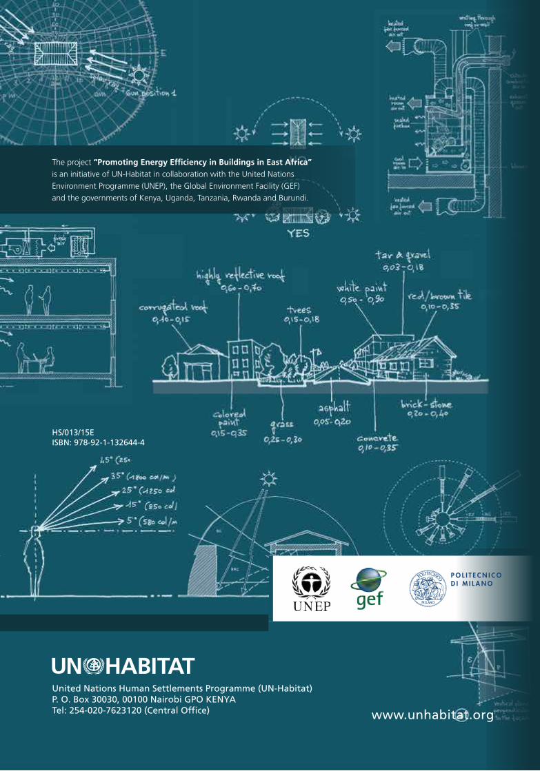
SUSTAINABLE BUILDING DESIGN FOR TROPICAL CLIMATESPrinciples and Applications for Eastern Africa
SUSTA
INA
BLE
BU
ILDIN
G D
ESIG
N FO
R T
RO
PIC
AL C
LIMA
TE
S
PR
INC
IPLE
S AN
D A
PP
LICA
TIO
NS FO
R E
AS
TE
RN
AFR
ICA
United Nations Human Settlements Programme (UN-Habitat) P. O. Box 30030, 00100 Nairobi GPO KENYA Tel: 254-020-7623120 (Central Office)
HS/013/15E ISBN: 978-92-1-132644-4
www.unhabitat.org
The project “Promoting Energy Efficiency in Buildings in East Africa” is an initiative of UN-Habitat in collaboration with the United NationsEnvironment Programme (UNEP), the Global Environment Facility (GEF) and the governments of Kenya, Uganda, Tanzania, Rwanda and Burundi.