SURVEYING (ACE002) · THEODOLITE AND TRAVERSE SURVEYING: Theodolite, description of transit...
98
LECTURE NOTES ON SURVEYING (ACE002) B. Tech III SEMESTER B SURESH Assistant Professor, CE Dept CIVIL ENGINEERING INSTITUTE OF AERONAUTICALENGINEERING (Autonomous) DUNDIGAL, HYDERABAD - 500043
Transcript of SURVEYING (ACE002) · THEODOLITE AND TRAVERSE SURVEYING: Theodolite, description of transit...

LECTURE NOTES
ON
SURVEYING
(ACE002)
B. Tech III SEMESTER
B SURESH
Assistant Professor, CE Dept
CIVIL ENGINEERING
INSTITUTE OF AERONAUTICALENGINEERING (Autonomous)
DUNDIGAL, HYDERABAD - 500043

SYLLABUS
UNIT – I
INTRODUCTION, LINEAR AND ANGULAR MEASUREMENTS:
Definitions, primary divisions of surveying, objectives, principles and classifications, plan and map, error due to wrong scale Linear and angular measurements; Direct and in direct methods, use of chain and tape, errors
in chaining, meridians, azimuths and bearings, declination, dip, computation of angle, errors due to local
attraction.
UNIT - II
LEVELING AND CONTOURING.
Leveling: Concept and terminology, temporary and permanent adjustments, method of leveling, height of
instrument and rise and fall method; Contouring: Characteristics and uses of contours; Methods of conducting
contour surveys and their plotting.
UNIT - III
COMPUTATION OF AREAS AND VOLUMES: Computation of areas directly from field measurements methods, computation of areas along irregular
boundaries and regular boundaries Embankments and cutting for a level section and two level sections with
and without transverse slopes, determination of the capacity of reservoir, volume of barrow pits.
UNIT - IV
THEODOLITE AND TRAVERSE SURVEYING:
Theodolite, description of transit theodolite, definitions and terms, temporary and permanent adjustments,
measurement of horizontal and vertical angles Trigonometrical leveling height and distance problems,
traverse survey and methods of traversing, closing errors in traversing.
UNIT – V
TACHEOMETRIC AND ADVANCED SURVEYING:
Tachometry: Stadia and tangential methods of tachometry. Distance elevation and depression formulae for
staff held in vertical and inclined position. Curves: Definition, types of curves, design and setting out, simple
and compound curves. Advanced Surveying: Basic principles of total station, global positioning system and
geographic information system List of Text Books / References / Websites / Journals / Others
Text Books:
1. Chandra A M, “Plane Surveying” and “Higher Surveying” New age International Pvt.Ltd., Publishers,
New Delhi, 2002.
2. Duggal S K, “Surveying (Vol – 1 & 2)”, Tata Mc.Graw Hill Publishing Co. Ltd. New Delhi, 2004.
Reference Books:
1. Surveying and Leveling by R. Subramanian, Second Edition Oxford University Press – 2012
2. Surveying Theory and Practice Seventh edition by James M. and Andeson Edward M. Mikhail
TATA McGraw Hill.
3. Arthur R Benton and Philip J Taety, Elements of Plane Surveying, McGraw Hill- 2000.
4. “Advanced Surveying Total Station GIS and Remote Sensing by SatheeshGopi, R. Sathi Kumar
and N.Madhu.
UNIT-1
INTRODUCTION
LECTURE 1
General:
Surveying is defined as “taking a general view of, by observation and
measurement determining the boundaries, size, position, quantity, condition, value etc. of
land, estates, building, farms mines etc. and finally presenting the survey data in a suitable
form”. This covers the work of the valuation surveyor, the quantity surveyor, the building
surveyor, the mining surveyor and so forth, as well as the land surveyor.
Another school of thought define surveying “as the act of making measurement
of the relative position of natural and manmade features on earth‟s surface and the
presentation of this information either graphically or numerically.
The process of surveying is therefore in three stages namely:
This part of the definition is important as it indicates the need to obtain an overall
picture of what is required before any type of survey work is undertaken. In land
surveying, this is achieved during the reconnaissance study.
Observation and Measurement
This part of the definition denotes the next stage of any survey, which in land
surveying constitutes the measurement to determine the relative position and sizes of
natural and artificial features on the land.
Presentation of Data:
The data collected in any survey must be presented in a form which allows the
information to be clearly interpreted and understood by others. This presentation may take
the form of written report, bills of quantities, datasheets, drawings and in land surveying
maps and plan showing the features on the land.
Types of Surveying
On the basis of whether the curvature of the earth is taken into account or not,
surveying can be divided into two main categories:
Plane surveying:
The type of surveying where the mean surface of the earth is considered as a plane
All angles are considered to be plane angles. For small areas less than 250 km2
plane
surveying can safely be used. For most engineering projects such as canal, railway,
highway, building, pipeline, etc constructions, this type of surveying is used. It is worth
noting that the difference between an arc distance of 18.5 km and the subtended chord
lying in the earth‟s surface is 7mm. Also the sum of the angles of a plane triangle and the
sum of the angles in a spherical triangle differ by 1second for a triangle on the earth‟s
surface having an area of 196km2

Geodetic surveying:
It is that branch of surveying, which takes into account the true shape of the earth
(spheroid).
Introduction
For easy understanding of surveying and the various components of the subject, we need
a deep understanding of the various ways of classifying it.
Objective
To enable the students have understanding of the various ways of classifying surveying
Classification Of Surveying
Surveying is classified based on various criteria including the instruments used, purpose,
the area surveyed and the method used.
Classification on the Basis of Instruments Used.
Based on the instrument used; surveys can be classified into;
i) Chain tape surveys
ii) Compass surveys
iii) Plane table surveys
iv) Theodolite surveys
Classification based on the surface and the area surveyed
i) Land survey
Land surveys are done for objects on the surface of the earth. It can be subdivided into:
(a) Topographic survey:
This is for depicting the (hills, valleys, mountains, rivers, etc) and manmade
features (roads, houses, settlements…) on the surface of the earth.
(b) Cadastral survey
It is used to determining property boundaries including those of fields, houses,
plots of land, etc.
(c) Engineering survey
It is used to acquire the required data for the planning, design and Execution of
engineering projects like roads, bridges, canals, dams, railways, buildings, etc.

City surveys:
The surveys involving the construction and development of towns including roads,
drainage, water supply, sewage street network, etc, are generally referred to as city
survey.
Marine or Hydrographic Survey:
Those are surveys of large water bodies for navigation, tidal monitoring, the
construction of harbors etc.
Astronomical Survey:
Astronomical survey uses the observations of the heavenly bodies (sun, moon, stars etc)
to fix the absolute locations of places on the surface of the earth
LECTURE 2
CLASSIFICATION ON THE BASIS OF PURPOSE
i) Engineering survey
ii) Control Survey:
Control survey uses geodetic methods to establish widely spaced vertical and
horizontal control points.
iii) Geological Survey
Geological survey is used to determine the structure and arrangement of rock
strata. Generally, it enables to know the composition of the earth.
iv) Military or Defense Survey
It is carried out to map places of military and strategic importance
iv) Archeological survey is carried out to discover and map ancient/relies of antiquity.
Classification Based On Instrument Used
i. Chain/Tape Survey:
This is the simple method of taking the linear measurement using a chain or tape
with no angular measurements made.
ii. Compass Survey:
Here horizontal angular measurements are made using magnetic compass with
the linear measurements made using the chain or tape.
iii. Plane table survey:
This is a quick survey carried out in the field with the measurements and drawings
made at the same time using a plane table.
iv. Leveling
This is the measurement and mapping of the relative heights of points on the
earth‟s surface showing them in maps, plane and charts as vertical sections or with
conventional
symbols.
Vi. Theodolite Survey:
Theodolite survey takes vertical and horizontal angles in order to establish
controls
CLASSIFICATION BASED ON THE METHOD USED
1. Triangulation Survey
In order to make the survey, manageable, the area to be surveyed is first covered
with series of triangles. Lines are first run round the perimeter of the plot, then the
details fixed in relation to the established lines. This process is called triangulation. The
triangle is preferred as it is the only shape that can completely over an irregularly shaped
area with minimum space left.
ii. Traverse survey:
If the bearing and distance of a place of a known point is known: it is possible to
establish the position of that point on the ground. From this point, the bearing and
distances of other surrounding points may be established. In the process, positions of
points linked with lines linking them emerge. The traversing is the process of
establishing these lines, is called traversing, while the connecting lines joining two
points on the ground. Joining two while bearing and distance is known as traverse A
traverse station is each of the points of the traverse, while the traverse leg is the straight
line between consecutive stations. Traverses may either be open or closed.
1. Closed Traverse:
When a series of connected lines forms a closed circuit, i.e. when the
finishing point coincides with the starting point of a survey, it is called as a „closed
traverse‟, here ABCDEA represents a closed traverse. (Fig 2.1 (a))
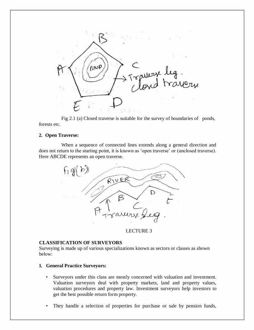
Fig 2.1 (a) Closed traverse is suitable for the survey of boundaries of ponds,
forests etc.
2. Open Traverse:
When a sequence of connected lines extends along a general direction and
does not return to the starting point, it is known as „open traverse‟ or (unclosed traverse).
Here ABCDE represents an open traverse.
LECTURE 3
CLASSIFICATION OF SURVEYORS
Surveying is made up of various specializations known as sectors or classes as shown
below:
1. General Practice Surveyors:
• Surveyors under this class are mostly concerned with valuation and investment.
Valuation surveyors deal with property markets, land and property values,
valuation procedures and property law. Investment surveyors help investors to
get the best possible return form property.
• They handle a selection of properties for purchase or sale by pension funds,

insurance companies, charities and other major investors. They also specialize in
housing policy advice, housing development and management.
2. Planning and Development Surveyors
• They are concerned with preparing planning applications and negotiating with
local authorities planners to obtain planning permission.
3. Building Surveyors
• Their work involves advising on the construction, maintenance, repair of all types
of residential and commercial property.
• The analysis of building defects is an important part of a building surveyor‟s
discipline.
4. The Quantity Surveyors
• They evaluate project cost and advice on alternative proposals. They also
mensure that each element of a project agrees with the cost plan allowance and that the
overall project remains within budget.
5. Rural Practice Surveyors:
• Surveyors in rural practice advice land owners, farmers and others with interests
in the countryside.
• They are responsible for the management of country estates and farms, the
planning and execution of development schemes for agriculture, forestation,
recreation, sales of properties and livestock.
6. Mineral Surveyors
• They plan the development and future of mineral workings. They work with local
authorities and the land owners on planning applications and appeals, mining
laws and working rights, mining subsidence and damage, the environmental
effects of land and deep underground mines.

7. Land surveyors:
• They measure land and its physical features accurately and record them in the
form of a map or plan for the purpose of planning new building and by local
authorities in managing roads, housing estates, and other facilities.
• They also undertake the positioning and monitoring for construction works.
LECTURE 4
BRANCHES OF SURVEYING
1. Aerial Surveying
Aerial surveys are undertaken by using photographs taken with special cameras
mounted in an aircraft viewed in pairs. The photographs produce three-
dimensional images of ground features from which maps or numerical data can be
produced usually with the aid of stereo plotting machines and computers.
2. Hydrographic Surveying (Hydro-Survey)

Hydro survey is undertaken to gather information in the marine environment such
as mapping out the coast lines and sea bed in order to produce navigational
charts.
• It is also used for off shore oil exploration and production, design, construction
and maintenance of harbors, inland water routes, river and sea defense, and
pollution control and ocean studies.
3. Geodetic Survey:
• In geodetic survey, large areas of the earth surface are involved usually on
national basis where survey stations are precisely located large distances apart.
Account is taken of the curvature of the earth, hence it involves advanced

Mathematical theory and precise measurements are required to be made.
• Geodetic survey stations can be used to map out entire continent, measure the
size and shape of the earth or in carrying out scientific studies such as
determination of the Earth‟s magnetic field and direction of continental drifts.
4. Plane Surveying
• In plane surveying relatively small areas are involved and the area under
consideration is taken to be a horizontal plane. It is divided into three branches.
- Cadastral surveying
- Topographical surveying
- Engineering surveying
5. Cadastral surveying
• These are surveys undertaken to define and record the boundary of properties,
legislative area and even countries.
• It may be almost entirely topographical where features define boundaries with the
topographical details appearing on ordinance survey maps.
• In the other hand, markers define boundaries corner or line points and little
account may be taken of the topographical features.

6. Topographical Survey
• These are surveys where the physical features on the earth are measured and
maps/plans prepared to show their relative positions both horizontally and
vertically.
• The relative positions and shape of natural and man –made features over an area
are established usually for the purpose of producing a map of the area of for
establishing geographical information system.

8. Engineering Survey
• These are surveys undertaken to provide special information for construction of
Civil Engineering and building projects.
.LECTURE 5
Reconnaissance:
• This is an exhaustive preliminary survey of the land to be surveyed. It may be
either ground reconnaissance or aerial reconnaissance survey.
• Reconnaissance is made on arrival to site during which an overall picture or view
of the area is obtained. The most suitable position of stations is selected, the
purpose of the survey and the accuracy required will be drawn, and finally the
method of observation will be established.
Objectives of reconnaissance
1. To ascertain the possibility of building or constructing route or track through the
area.
2. To choose the best one or more routes and record on amp
3. To estimate probable cost and draft airport.
The basic principles and process surveying
Introduction
So far, we have discussed the meaning, object and major classifications of surveying.
Now let us move further to discuss the basic principles and process of surveying.
Objectives.
· To enable students understand the basic principles of surveying.
· To expose the students to the process of surveying.

LECTURE 6
BASIC PRINCIPLES IN SURVEYING
PRINCIPLE OF WORKING FROM WHOLE TO PART
• It is a fundamental rule to always work from the whole to the part. This implies a
precise control surveying as the first consideration followed by subsidiary detail
surveying.
• This surveying principle involves laying down an overall system of stations whose
positions are fixed to a fairly high degree of accuracy as control, and then the survey
of details between the control points may be added on the frame by less elaborate
methods.
• Once the overall size has been determined, the smaller areas can be surveyed in the
knowledge that they must (and will if care is taken) put into the confines of the main
overall frame.
• Errors which may inevitably arise are then contained within the framework of the
control points and can be adjusted to it.
Surveying is based on simple fundamental principles which should be taken into
consideration to enable one get good results.
(a) Working from the whole to the part
It is achieved by covering the area to be surveyed with a number of
spaced out control point called primary control points called primary control points whose
pointing have been determined with a high level of precision using sophisticated
equipments. Based on these points as theoretic, a number of large triangles are drawn.
Secondary control points are then established to fill the gaps with lesser precision than the
primary control points. At a more detailed and less precise level, tertiary control points at
closer intervals are finally established to fill in the smaller gaps. The main purpose of
surveying from the whole to the part is to localize the errors as working the other way
round would magnify the errors and introduce distortions in the survey. In partial terms,
this principle involves covering the area to be surveyed with large triangles. These are
further divided into smaller triangles and the process continues until the area has been
sufficiently covered with small triangles to a level that allows detailed surveys to be made
in a local level. Error is in the whole operation as the vertices of the large triangles are
fixed using higher precision instruments.
(b) Using measurements from two control parts to fix other points.
Given two points whose length and bearings have been accurately
determined, a line can be drawn to join them hence surveying has control reference
points. The locations of various other points and the lines joining them can be fixed by
measurements made from these two points and the lines joining them. For an example, if
A and B are the control points, the following operations can be performed to fix other
points.
i) Using points A and B as the centers ascribe arcs and fix (where they intersect).
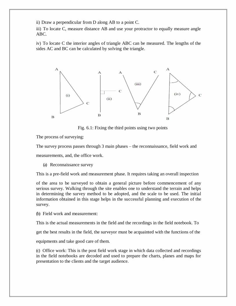
ii) Draw a perpendicular from D along AB to a point C.
iii) To locate C, measure distance AB and use your protractor to equally measure angle
ABC.
iv) To locate C the interior angles of triangle ABC can be measured. The lengths of the
sides AC and BC can be calculated by solving the triangle.
Fig. 6.1: Fixing the third points using two points
The process of surveying:
The survey process passes through 3 main phases – the reconnaissance, field work and
measurements, and, the office work.
(a) Reconnaissance survey
This is a pre-field work and measurement phase. It requires taking an overall inspection
of the area to be surveyed to obtain a general picture before commencement of any
serious survey. Walking through the site enables one to understand the terrain and helps
in determining the survey method to be adopted, and the scale to be used. The initial
information obtained in this stage helps in the successful planning and execution of the
survey.
(b) Field work and measurement:
This is the actual measurements in the field and the recordings in the field notebook. To
get the best results in the field, the surveyor must be acquainted with the functions of the
equipments and take good care of them.
(c) Office work: This is the post field work stage in which data collected and recordings
in the field notebooks are decoded and used to prepare the charts, planes and maps for
presentation to the clients and the target audience.

LECTURE 7
IMPORTANCE OF SCIENTIFIC HONESTY
• Honesty is essential in booking notes in the field and when plotting and
computations in the office. There is nothing to be gained from cooking the survey
or altering dimensions so that points will tie-in on the drawing. It is utterly
unprofessional to betray such trust at each stage of the survey.
• This applies to the assistants equally as it does to the surveyor in charge.
Assistants must also listen carefully to all instructions and carry them out to the
later without questions.
CHECK ON MEASUREMENTS
• The second principle is that; all survey work must be checked in such a way that
an error will be apparent before the survey is completed.
• Concentration and care are necessary in order to ensure that all necessary
measures are taken to the required standard of accuracy and that nothing is
omitted. Hence they must be maintained in the field at all times.
• Surveyor on site should be checking the correctness of his own work and that of
others which is based on his information.
• Check should be constantly arranged on all measurements wherever possible.
Check measurements should be conducted to supplement errors on field. Pegs
can be moved, sight rails etc
• Survey records and computations such as field notes, level books, field books,
setting out record books etc must be kept clean and complete with clear notes and
diagrams so that the survey data can be clearly understood by others. Untidy and
anonymous figures in the field books should be avoided.
• Like field work, computations should be carefully planned and carried out in a
systemic manner and all field data should be properly prepared before
calculations start. Where possible, standardized tables and forms should be used
to simplify calculations. If the result of a computation has not been checked, it is
considered unreliable and for this reason, frequent checks should be applied to
every calculation procedure.
• As a check, the distances between stations are measured as they are plotted, to
see that there is correspondence with the measured horizontal distance. Failure to
match indicates an error in plotting or during the survey.
• If checks are not done on observations, expensive mistake may occur. It is always
preferable to take a few more dimensions on site to ensure that the survey will
resolve itself at the plotting stage.

ACCURACY AND PRECISION
These terms are used frequently in engineering surveying both by manufacturers when
quoting specifications for their equipments and on site by surveyors to describe results
obtained from field work.
• Accuracy allows a certain amount of tolerance (either plus or minus) in a
measurement, while;
• Precision demands exact measurement. Since there is no such things as an
absolutely exact measurement, a set of observations that are closely grouped
together having small deviations from the sample mean will have a small
standard error and are said to be precise.
ECONOMY OF ACCURACY AND ITS INFLUENCE ON CHOICE OF
EQUIPMENTS
• Survey work is usually described as being to a certain standard of accuracy which
in turn is suited to the work in hand. Bearing in mind the purpose for which the
survey is being made, it is better to achieve a high degree of accuracy than to aim
for precision (exactness) which if it were to be altered would depend not only on
the instrument used but also on the care taken by the operator to ensure that his
work was free from mistake.
• Always remember that, the greater the effort and time needed both in the field
and in the office, the more expensive survey will be for the client. The standard
accuracy attained in the field must be in keeping with the size of the ultimate
drawings.
• The equipment selected should be appropriate to the test in hand. An important
factor when selecting equipment is that the various instruments should produce
roughly the same order of precision. A steel chain best at an accuracy of 1/500 to
1/1000 would be of little use for work requiring an accuracy of 1/1000. Similarly,
the Theodolite reading to one second would be pointless where a reading to one
minute insufficient.
• Having selected the equipment necessary, the work should be thoroughly
checked and if found wanting should be adjusted, repaired or replaced or have
allowance calculated for its deficiencies. This task will be less tedious if field
equipment is regularly maintained.
Horizontal Distance Measurement
One of the basic measurements in surveying is the determination of the
distance between two points on the earth‟s surface for use in fixing position, set
out and in scaling. Usually spatial distance is measured. In plane surveying, the
distances measured are reduced to their equivalent horizontal distance either by the

procedures used to make the measurement or by applying numerical corrections
for the slope distance (spatial distance). The method to be employed in measuring
distance depends on the required accuracy of the measurement, and this in turn
depends on purpose for which the measurement is intended.
Pacing: –
Where approximate results are satisfactory, distance can be obtained by pacing
(the number of paces can be counted by tally or pedometer registry attached to one leg)
Average pace length has to be known by pacing a known distance several times and
taking the average. It is used in reconnaissance surveys& in small scale mapping
Odometer of a vehicle: -
Based on diameter of tires (no of revolutions X wheel diameter); this method gives
a fairly reliable result provided a check is done periodically on a known length. During
each measurement a constant tyre pressure has to be maintained.
Tachometry:
Distance can be can be measured indirectly by optical surveying instruments like
Theodolite. The method is quite rapid and sufficiently accurate for many types of
surveying operations.
Taping (chaining): - this method involves direct measurement of distances with a tape or
chain. Steel tapes are most commonly used .It is available in lengths varying from 15m
to 100m. Formerly on surveys of ordinary precision, lengths of lines were measured
with chains.
Electronic Distance Measurement (EDM): - are indirect distance measuring instruments
that work using the invariant velocity of light or electromagnetic waves in vacuum. They
have high degree of accuracy and are effectively used for long distances for modern
surveying operations.
LECTURE 8
CHAIN SURVEYING
This is the simplest and oldest form of land surveying of an area using linear
measurements only. It can be defined as the process of taking direct measurement,
although not necessarily with a chain.
EQUIPMENTS USED IN CHAIN SURVEYING
These equipments can be divided into three, namely
(i) Those used for linear measurement. (Chain, steel band, linear tape)
(ii) Those used for slope angle measurement and for measuring right angle (Eg.
Abney level, clinometers, cross staff, optical squares)
(iii) Other items (Ranging rods or poles, arrows, pegs etc).
1. Chain:-
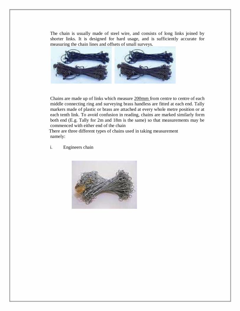
The chain is usually made of steel wire, and consists of long links joined by
shorter links. It is designed for hard usage, and is sufficiently accurate for
measuring the chain lines and offsets of small surveys.
Chains are made up of links which measure 200mm from centre to centre of each
middle connecting ring and surveying brass handless are fitted at each end. Tally
markers made of plastic or brass are attached at every whole metre position or at
each tenth link. To avoid confusion in reading, chains are marked similarly form
both end (E.g. Tally for 2m and 18m is the same) so that measurements may be
commenced with either end of the chain
There are three different types of chains used in taking measurement
namely:
i. Engineers chain

ii. Günter‟s chain
2 Steel Bands:
This may be 30m, 50m or 100m long and 13mm wide. It has handles similar to
those on the chain and is wound on a steel cross. It is more accurate but less
robust than the chain. The operating tension and temperature for which it was
graduated should be indicated on the band.
3 Tapes:
Tapes are used where greater accuracy of measurements are required, such as the
setting out of buildings and roads. They are 15m or 30m long marked in metres,
centimeter and millimeters. Tapes are classified into three types;

i. Linen or Linen with steel wire woven into the fabric;
These tapes are liable to stretch in use and should be frequently tested for
length. They should never be used on work for which great accuracy is
required.
ii. Fibre Glass Tapes: These are much stronger than lines and will
not stretch in use.
iii. Steel tapes: These are much more accurate, and are usually used for
setting out buildings and structural steel works. Steel tapes are available in
various lengths up to 100m (20m and 30m being the most common)
encased in steel or plastic boxes with a recessed winding lever or mounted
on open frames with a folding winding lever.
4. Arrows:
Arrow consists of a piece of steel wire about 0.5m long, and is used for marking
temporary stations. A piece of colored cloth, white or red ribbon is usually
attached or tied to the end of the arrow to be clearly seen on the field.

5. Pegs
Pegs are made of wood 50mm x 50mm and some convenient length. They are
used for points which are required to be permanently marked, such as intersection
points of survey lines. Pegs are driven with a mallet and nails are set in the tops.
6. Ranging Rod:
These are poles of circular section 2m, 2.5m or 3m long, painted with
characteristic red and white bands which are usually 0.5m long and tipped with a
pointed steel shoe to enable them to be driven into the ground. They are used in
the measurement of lines with the tape, and for marking any points which need to
be seen.
7. Optical Square:
This instrument is used for setting out lines at right angle to main chain line. It is
used where greater accuracy is required. There are two types of optical square,
one using two mirrors and the other a prism.

• The mirror method is constructed based on the fact that a ray of light is reflected
from a mirror at the same angle as that at which it strikes the mirror.
• The prism square method is a simplified form of optical square consisting of a
single prism. It is used in the same way as the mirror square, but is rather more
accurate.
8 Cross Staff:
This consists of two pairs of vanes set at right angle to each other with a wide and
narrow slit in each vane. The instrument is mounted upon a pole, so that when it is
set up it is at normal eye level. It is also used for setting out lines at right angle to the
main chain line.
9. Clinometers
This instrument is used for measuring angles of ground slopes (slope angle). They
are of several form, the common form is the WATKING‟S CLINOMETER, which
consist of a small disc of about 60mm diameter. A weighted ring inside the disc can
be made to hang free and by sighting across this graduated ring angle of slopes can
be read off. It is less accurate than Abney Level.

9 Abney Level
This instrument is generally used to obtain roughly the slope angle of the ground.
It consists of a rectangular, telescopic tube (without lenses) about 125mm long
with a graduated arc attached. A small bubble is fixed to the vernier arm, once
the image of the bubble is seen reflected in the eyepiece the angle of the line of
sight can be read off with the aid of the reading glass.
LECTURE 9
NECESSARY PRECAUTIONS IN USING CHAIN SURVEYING
INSTRUMENTS
1. After use in wet weather, chains should be cleaned, and steel tapes should be
dried and wiped with an oily rag.
2. A piece of colored cloth should be tied to arrow (or ribbon – attached) to enable
them to be seen clearly on the field.
3. Ranging rods should be erected as vertical as possible at the exact station point.
4. The operating tension and temperature for which steel bands/tapes are graduated
should be indicated.
5. Linen tapes should be frequently tested for length (standardized) and always after
repairs.
6. Always keep tapes reeled up when not in use.
GENERAL PROCEDURE IN MAKING A CHAIN SURVEY
1. Reconnaissance: Walk over the area to be surveyed and note the general layout, the
position of features and the shape of the area.
2. Choice of Stations: Decide upon the framework to be used and drive in the station
pegs to mark the stations selected.
3. Station Marking: Station marks, where possible should be tied - in to a permanent
objects so that they may be easily replaced if moved or easily found during the

survey. In soft ground wooden pegs may be used while rails may be used on roads
or hard surfaces.
4. Witnessing: This consists of making a sketch of the immediate area around the
station showing existing permanent features, the position of the stations and its
description and designation. Measurements are then made from at least three
surrounding features to the station point and recorded on the sketch.
The aim of witnessing is to re-locate a station again at much later date even by
others after a long interval.
5. Offsetting:-Offsets are usually taken perpendicular to chain lines in order to dodge
obstacles on the chain line.
6. Sketching the layout on the last page of the chain book, together with the date and
the name of the surveyor, the longest line of the survey is usually taken as the base
line and is measured first.
CRITERIA FOR SELECTING A SURVEY LINES/OFFSETS
During reconnaissance, the following points must be borne in mind
as the criteria to provide the best arrangement of survey lines,
a. Few survey lines: the number of survey lines should be kept to a minimum but must
be sufficient for the survey to be plotted and checked.
b. Long base line: A long line should be positioned right across the site to form a base
on which to build the triangles.
c. Well conditioned triangle with angles greater than 30o
and not exceeding 150o: It
is preferable that the arcs used for plotting should intersect as close as 90o
in order to
provide sharp definition of the stations point.
d. Check lines: Every part of the survey should be provided with check lines that are
positioned in such a way that they can be used for off- setting too, in order to save
any unnecessary duplication of line.
e. Obstacles such as steep slopes and rough ground should be avoided as far as
possible.
f. Short offsets to survey lines (close feature preferably 2m) should be selected: So
that measuring operated by one person can be used instead of tape which needs two
people.
g. Stations should be positioned on the extension of a check line or triangle. Such
points can be plotted without the need for intersecting arcs.

Ranging:
Ranging involves placing ranging poles along the route to be measures so as to
get a straight line. The poles are used to mark the stations and in between the stations.
LECTURE 10
ERRORS IN SURVEYING
• Surveying is a process that involves observations and measurements with a wide
range of electronic, optical and mechanical equipment some of which are very
sophisticated.
• Despite the best equipments and methods used, it is still impossible to take
observations that are completely free of small variations caused by errors which
must be guided against or their effects corrected.
TYPES OF ERRORS
1. Gross Errors
• These are referred to mistakes or blunders by either the surveyor or his assistants
due to carelessness or incompetence.
• On construction sites, mistakes are frequently made by in – experienced
Engineers or surveyors who are unfamiliar with the equipment and method they
are using.
• These types of errors include miscounting the number of tapes length, wrong
booking, sighting wrong target, measuring anticlockwise reading, turning
instruments incorrectly, and displacement of arrows or station market.
• Gross errors can occur at any stage of survey when observing, booking,
computing or plotting and they would have a damaging effect on the results if
left uncorrected.
• Gross errors can be eliminated only by careful methods of observing booking
and constantly checking both operations.
2. Systematic or Cumulative Errors
• These errors are cumulative in effect and are caused by badly adjusted instrument
and the physical condition at the time of measurement must be considered in this
respect. Expansion of steel, frequently changes in electromagnetic distance
(EDM) measuring instrument, etc are just some of these errors.
• Systematic errors have the same magnitude and sign in a series of measurements
that are repeated under the same condition, thus contributing negatively or
positively to the reading hence, makes the readings shorter or longer.
• This type of error can be eliminated from a measurement using corrections (e.g.
effect of tension and temperature on steel tape).
• Another method of removing systematic errors is to calibrate the observing
equipment and quantify the error allowing corrections to be made to further
observations.
• Observational procedures by re-measuring the quantity with an entirely different
method using different instrument can also be used to eliminate the effect of
systematic errors.
3. Random or Compensating Errors
• Although every precaution may be taken certain unavoidable errors always exist
in any measurement caused usually by human limitation in reading/handling of
instruments.
• Random errors cannot be removed from observation but methods can be adopted
to ensure that they are kept within acceptable limits.
• In order to analyze random errors or variable, statistical principles must be used
and in surveying their effects may be reduced by increasing the number of
observations and finding their mean. It is therefore important to assume those
random variables are normally distributed.
LECTURE 11
Corrections to Linear Measurement and their Application:-
The following corrections are to be applied to the linear measurements with
a chain or a tape where such accuracy is required.
(i) Pull correction,
(ii) Temperature correction
(iii) Standard length correction
(iv) Sag correction
(v) Slope correction
(vi) Mean sea level correction.
Pull Correction:-
A chain or tape of nominal length „L‟ having cross sectional area of the link
F
or that of a tape, as the case may be, equal to A and standardized under a pull Ps is
employed to measure a length at a pull PF. If Young‟s modulus of elasticity of the
(PF PS )L material is E the extension of its length is =
AE
The recorded length is less than the actual by this extension. The error is
here, -ve, the actual length is obtained by adding the extension to L. The correction is
+ ve. If PF is less than PS the error will be +ve and correction –ve.
Temperature Correction:-
A chain or a tape of nominal length „L‟ standardized at temperature TS and
having cross sectional area A is employed to measured length at temperature TF
being the coefficient of linear expansion of the material of the chain or tape per unit rise
of temperature, –TS)L.
If TF is more than TS, recorded length is less than the actual by the amount
of extension. The error is –ve and the correction to the length L is +ve by the amount
of extension. If the field temperature TF is less than TS the error is =+ve and the
corrections is–ve.
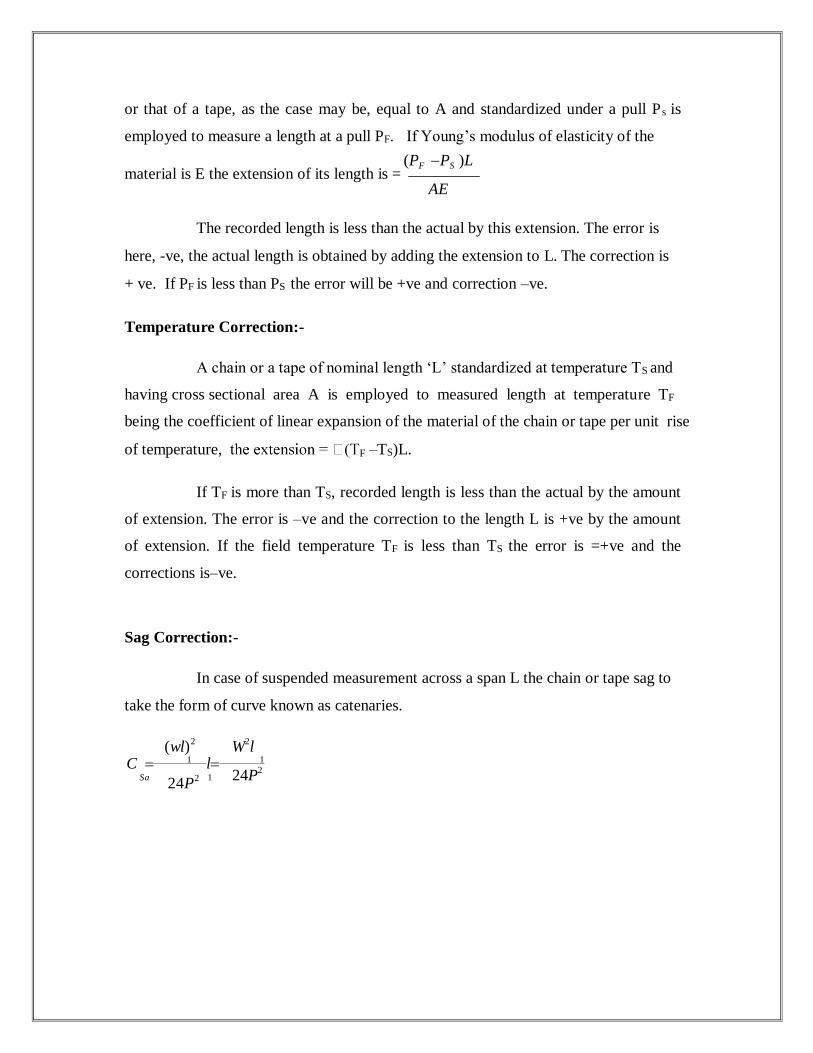
Sag Correction:-
In case of suspended measurement across a span L the chain or tape sag to
take the form of curve known as catenaries.
(wl)2
W2l
C 1 l 1
Sa 24P
2 1 24P2

Where w= weight of the tape per metre length W=
Total weight of the tape
P=pull applied (in N)
l1 = The length of tape suspended between two supports
l = length of the tape = n l1 (in m) Sag
correction is always negative.
LECTURE 12
TRIANGULATION
Because, at one time, it was easier to measure angles than it was distance, triangulation was
the preferred method of establishing the position of control points.
Many countries used triangulation as the basis of their national mapping system. The
procedure was generally to establish primary triangulation networks, with triangles having
sides ranging from 30 to 50 km in length. The primary trig points were fixed at the corners of
these triangles and the sum of the measured angles was correct to ±3. These points were
usually established on the tops of mountains to afford long, uninterrupted sight lines. The
primary network was then noted with points at closer intervals connected into the primary
triangles. This secondary network had sides of 10– 20 km with a reduction in observational
accuracy. Finally, a third order net, adjusted to the secondary control, was established at 3–5-
km intervals and fourth-order points fixed by intersection. Figure 12.2 illustrates such a
triangulation system established by the Ordnance Survey of Great Britain and used as control
for the production of national maps. The base line and check base line would be measured by
invar tapes in catenary and connected into the triangulation by angular extension procedures.
This approach is classical triangulation, which is now obsolete. The more modern approach
would be to measure the base lines with EDM equipment and to include many more
measured lines in the network, to afford greater control of scale error. Although the areas
involved in construction are relatively small compared with national surveys (resulting in the
term „micro triangulation‟) the accuracy required in establishing the control surveys is
frequently of a very high order, e.g. long tunnels or dam deformation measurements.

The principles of the method are illustrated by the typical basic figures shown in Figure
If all the angles are measured, then the scale of the network is obtained by the
measurement of one side only, i.e. the base line. Any error, therefore, in the measurement
of the base line will result in scale error throughout the network. Thus, in order to control
this error, check baseline should be measured at intervals the scale
Error is defined as the difference between the measured and computed check base.
Using the base line and adjusted angles the remaining sides of the triangles may be
found and subsequently the coordinates of the control stations. Triangulation is best
suited to open, hilly country, affording long sights well clear of intervening terrain. In
urban areas, roof- top triangulation is used, in which the control stations are situated on
the roofs of accessible buildings. (a) Chain of simple triangles, (b) braced quadrilaterals
and (c) polygons with central points

LECTURE 13
General procedure:
(1) Reconnaissance of the area, to ensure the best possible positions for stations and base
lines.
(2) Construction of the stations.
(3) Consideration of the type of target and instrument to be used and also the method of
observation.
All of these depend on the precision required and the length of sights involved.
(4) Observation of angles and base-line measurements. (5) Computation: base line reduction, station and figural adjustment, coordinates of
stations by direct methods.
A general introduction to triangulation has been presented, aspects of which will now
be dealt with in detail.
(1) Reconnaissance is the most important aspect of any well-designed surveying project.
Its main function is to ensure the best positions for the survey stations commensurate
with well-conditioned figures, ease of access to the stations and economy of observation.
A careful study of all existing maps or plans of the area is essential. The best position for
the survey stations can be drawn on the plan and the overall shape of the network
studied. While chains of single triangles are the most economic to observe, braced
quadrilaterals provide many more conditions of adjustment and are at their strongest
when square shaped. Using the contours of the plan, profiles between stations can be
plotted to ensure indivisibility. Stereo-pairs of aerial photographs, giving a three-
dimensional view of the terrain, are useful in this respect. Whilst every attempt should
be made to ensure that there are no angles less than 25°, if a small angle cannot be
avoided it should be situated opposite a side which does not enter into the scale
computation. When the paper triangulation is complete, the area should then be visited
and the site of every station carefully investigated. With the aid of binoculars,
indivisibility between stations should be checked and ground-grazing rays avoided.
Since the advent of EDM, base-line sitting is not so critical. Soil conditions should be
studied to ensure that the ground is satisfactory for the construction of long-term survey
stations. Finally, whilst the strength of the network is a function of its shape, the purpose
of the survey stations should not be forgotten and their position located accordingly.
(2) Stations must be constructed for long-term stability .A complete referencing of the
station should then be carried out in order to ensure its location at a future date.
(3) As already stated, the type of target used will depend on the length of sight involved
and the accuracy required for highly precise networks, the observations may be carried
out at night when refraction is minimal. In such a case, signal lamps would be the only
type of target to use. For short sights it may be possible to use the precise targets shown
in Figure 13.1 Whatever form the target takes, the essential considerations are that it
should be capable of being accurately centered over the survey point and afford the
necessary size and shape for accurate bisection at the observation distances used.
(4) In triangulation the method of directions would inevitably be used and the horizon
closed.Anappropriatenumberofsetswouldbetakenoneachface.Thebaselineand

check base would most certainly be measured by EDM, with all the necessary
corrections made to ensure high accuracy.
(5) Since the use of computers is now well established, there is no reason why a least
squares adjustment using the standard variation of coordinates method should not be
carried out. Alternatively the angles may be balanced by simpler, less rigorous methods
known as „equal shifts‟. On completion, the sides may be computed using the sine rule
and finally the coordinates of each survey point obtained. If the survey is to be
connected to the national mapping system of the country, then all the baseline
measurements must be reduced to MSL and multiplied by the local scale factor. As
many of the national survey points as possible should be included in the scheme.
Interchangeable target and tribatch

LECTURE 14
Overcoming obstacles during chaining:
Agor (1993) classified the various types of obstacles encountered in the course of
chaining into three
· Obstacles which obstruct ranging but not chaining
· Obstacles which obstruct chaining but not ranging
· Obstacle which obstruct both ranging and chaining
Obstacles that obstruct ranging but not chaining
Such a problem arises when a rising ground or a jungle area interrupts the
chain line. Here the end stations are not interred visible.
There may be two cases:-
Case I :
The end stations may be visible from some intermediate points on the rising
ground. In this case, reciprocal ranging is resorted to and the chaining is done by the
stepping method.
Case II:
The end stations are not visible from intermediate points when a jungle area
comes across the chain line. In this case the obstacle may be crossed over using a
random line as explained below:

Fig 14.1 (1.14)
Let „AB‟ be the actual chain line which can be ranged and extended because
of interruption by a jungle. Let the chain line be extended up to „R‟. A point „P‟ is
selected on the chain line and a random line „PT‟ is taken in a suitable direction. Points
C , D and E are selected on the random line and perpendicular are projected from them.
The perpendicular at „C‟ meets the chain line at C1.
Theoretically, the perpendiculars at „D‟ and „E‟ will meet the chain line at D1
and E1. Now the distances PC, PD, PE and CC1 are measured (Fig 14.1(1.14)) from
triangles PDD1 and PCC1.
DD1 CC1
PD PC
DD1 CC1 PD
PC
---- (1)
Again, from triangles PEE1 and PCC1 –
EE1 CC1
PE PC

EE1 CC1 PE
PC
----- (2)
From (1) and (2), the lengths DD1 and EE1 are calculated. These calculated
distances are measured along the perpendiculars at ‘D’ and ‘E’. Points D1 and E1should
lie in the chain line AB, which can be extended accordingly.
Distance PE1 =
Obstacles which obstruct chaining but not ranging:
Water bodies like lakes, ponds and rivers are typical examples of obstacles in this
category. It is possible to chain around these obstacles by using the following methods.
i. By constructing rectangles: Chaining had reached A and encountered an obstacle. To
get to B, mark A and B with an arrow. Set of perpendiculars AC and BD high enough to
clear the obstacles. Join and measure DC which now equals AB. This allows chaining to
continue from B.
ii. By constructing similar triangles:
To continue chaining from B, fix a point C away from the obstacle. Range a pole at D to
align with AC hence AC = CD. In line with BC range another point E in line with BC.
Hence BC= CE.
Measure ED which equals AB hence chaining can continue from B.
PE 2 EE
2
1

Obstacle which obstruct both ranging and chaining
GD = (FC x GA) / FA
HE = ( FC x HA ) / FA

LECTURE 15
UNIT 2
COMPASS SURVEYING
Introduction:
Another type of survey instrument that forms the subject of this section is the compass.
Here, we will explain the meaning, types of compass survey and also introduce and
discus the concept of bearing.
Objectives
• To introduce the students to the meaning and types of compass survey
• To enable students understand the concept of
bearing
Meaning and types of compass survey
In compass survey, the direction of the survey line is measured by the use
of a magnetic compass while the lengths are by chaining or taping. Where the area
to be surveyed is comparatively large, the compass survey is preferred, whereas if
the area is small in extent and a high degree of accuracy is desired, then chain
survey is adopted. However, where the compass survey is used, care must be taken
to make sure that magnetic disturbances are not present. The two major primary
types of survey compass are: the prismatic compass and surveyors compass
Compass surveys are mainly used for the rapid filling of the detail in larger surveys and
for explanatory works. It does not provide a very accurate determination of the bearing
of a line as the compass needle aligns itself to the earth‟s magnetic field which does not
provide a constant reference point.

LECTURE 16
THE PRISMATIC COMPASS
This is an instrument used for the measurement of magnetic bearings. It is small and
portable usually carried on the hand. This Prismatic Compass is one of the two main
kinds of magnetic compasses included in the collection for the purpose of measuring
magnetic bearings, with the other being the Surveyor's Compass. The main difference
between the two instruments is that the surveyor's compass is usually larger and more
accurate instrument, and is generally used on a stand or tripod.
• The prismatic compass on the other hand is often a small instrument which is
held in the hand for observing, and is therefore employed on the rougher
classes of work. The graduations on this prismatic compass are situated on a
light aluminum ring fastened to the needle, and the zero of the graduations
coincides with the south point of the needle. The graduations therefore remain
stationary with the needle, and the index turns with the sighting vanes. Since
the circle is read at the observer's (rather than the target's) end, the graduations
run clockwise from the south end of the needle (0º to 360º), whereas in the
surveyor's compass, the graduations run anti-clockwise from north.
• The prismatic attachment consists of a 45º reflecting prism with the eye and
reading faces made slightly convex so as to magnify the image of the
graduations. The prism is carried on a mounting which can be moved up and
down between slides fixed on the outside of the case.
• The purpose of this up-and-down movement is to provide an adjustment for
focusing. The image of the graduations is seen through a small circular aperture
in the prism mounting, and immediately above this aperture is a small V cut on

top of the mounting, over which the vertical wire in the front vane may be
viewed. Using the V cut, the vertical wire and the station whose bearing is
required are viewed in one line, the bearing is directly read off the graduated
arc at the point immediately underneath the vertical wire.
• The mirror located in front of the forward vane slides up and down the vane,
and is hinged to fold flat over it or to rest inclined at any angle with it. This
mirror is used for solar observations, or for viewing any very high object, and
is not a normal fitting to a compass. The two circular discs in front of the back
vane are dark glasses which can be swung in front of the vane when solar
observations are being taken.
COMPONENTS OF A PRISMATIC COMPASS
Prismatic compass consists of a non-magnetic metal case with a glass top and
contain the following:
Elements of prismatic compass
Cylindrical metal box:
Cylindrical metal box is having diameter of 8to 12 cm. It protects the compass
and forms entire casing or body of the compass. It protect compass from dust,

rain etc.
Pivot:
pivot is provided at the center of the compass and supports freely
suspended magnetic needle over it.
lifting pin and lifting lever: lifting pin is provided just below the sight vane. When the sight vane is
folded, it presses the lifting pin. The lifting pin with the help of lifting lever then
lifts the magnetic needle out of pivot point to prevent damage to the pivoted.
Magnetic needle: Magnetic needle is the heart of the instrument. This needle
measures angle of a line from magnetic meridian as the needle always remains
pointed towards north South Pole at two ends of the needle when freely
suspended on any support.
Graduated circle or ring:
This is an aluminum graduated ring marked with 0o
to 360o
to
measures all possible bearings of lines, and attached with the magnetic needle.
The ring is graduated to half degree.
Prism :
prism is used to read graduations on ring and to take exact reading
by compass. It is placed exactly opposite to object vane. The prism hole is
protected by prism cap to protect it from dust and moisture.
Object vane:
Object vane is diametrically opposite to the prism and eye vane.
The object vane is carrying a horse hair or black thin wire to sight object in line
with eyesight.
Eye vane:
Eye vane is a fine slit provided with the eye hole at bottom to bisect
the object from slit.
Glass cover: It covers the instrument box from the top such that needle and
graduated ring is seen from the top.
Sun glasses:
These are used when some luminous objects are to be bisected.
Reflecting mirror:
It is used to get image of an object located above or below the
instrument level while bisection. It is placed on the object vane.
Spring break or brake pin: to damp the oscillation of the needle before taking a reading and to
bring it to rest quickly, the light spring break attached to the box is brought in
contact with the edge of the ring by gently pressing inward the brake pin

LECTURE 17
Temporary adjustment of prismatic compass
The following procedure should be adopted after fixing the prismatic compass on
the tripod for measuring the bearing of a line.
Centering :
Centering is the operation in which compass is kept exactly over
the station from where the bearing is to be determined. The centering is checked
by dropping a small pebble from the underside of the compass. If the pebble falls
on the top of the peg then the centering is correct, if not then the centering is
corrected by adjusting the legs of the tripod.
Leveling :
Leveling of the compass is done with the aim to freely swing the
graduated circular ring of the prismatic compass. The ball and socket
arrangement on the tripod will help to achieve a proper level of the compass.
This can be checked by rolling round pencil on glass cover.
Focusing: The prism is moved up or down in its slide till the graduations on
the aluminum ring are seen clear, sharp and perfect focus. The position of the
prism will depend upon the vision of the observer.
OPERATION PROCEDURE
• Remove the corner and open out the prism and window, holding the
compass as level as possible.
• Then focus the prism by raising or lowering its case until the divisions
appear sharp and clear. If necessary with the needle on to its pivot.
• Holding the compass box with the thumb under the prism and the
forefinger near the stud, sight through the objector station lowering the eye
to read the required bearing as soon as the needle comes to rest naturally.
• The bearing read will be a forward bearing and normally a “whole circle”
bearing clockwise angle between 0o to360
o.

LECTURE 18
VARIATION IN DECLINATION
The position of the magnetic poles is not fixed and the North magnetic pole tends
to wander more than the south causing alterations in the positions of the isogonic
lines from time to time. The angle of declination at any point is therefore not
constant subject to the following variations;
1. Secular Variation:
This causes the largest variation in magnetic declination. It is a slow
continuous swing with a cycle of about 400 to 500 years. Because of this
large movement, the date, the declination and the approximate rate of
annual change should be given for any magnetic orientation of survey.
2. Diurnal Variation:
This is a swing of the compass needle about its mean daily position.
3. Periodic Variation:
This is a minor variation of the magnetic meridian during the week, a lunar
month, year, eleven years, etc.
4. Irregular Variation: These are caused by magnetic storms which can
produce sudden variations of the magnetic meridian.
Magnetic Bearing
The magnetic bearing of a survey line is the angle between the direction of the line
and the direction of the magnetic meridian at the beginning of the line.
Magnetic Meridian
• The magnetic meridian at any place is the direction obtained by observing the
position of a freely supported magnetized needle when it comes to rest uninfluenced
by local attracting forces.
• Magnetic meridians run roughly north –south and follow the varying trend of the
earth‟s magnetic field. The direction of a magnetic meridian does not coincide with
the true or geographical meridian which gives the direction of the true North pole
except in certain places.
Angle of Declination:
It is defined as the angle between the direction of the magnetic meridian and the true
meridian at any point.

LECTURE 19
Surveyor’s Compass:
Similar to the prismatic compass but with few modifications, the surveyors compass is
an old form of compass used by surveyors. It is used to determine the magnetic bearing
of a given line and is usually used in connection with the chain or compass survey.
Bearing
The bearing is the angular direction measured clockwise starting from North with
reference to the observer. The reference North may be true or magnetic. While the true
bearing is the angular direction measured in a place with the direction of true or
geographical north; the magnetic bearing is the angle which it makes with the direction
of Magnetic North measured in the clockwise direction.

LECTURE 20
Back and Fore bearing:
Introduction:
In this section, we will examine the back and fore bearing; and the steps to be taken
when traversing with compass survey.
Back and fore bearing
Fore bearing is the compass bearing of a place taken from a status to the other in the
direction that the survey is being carried out. The back bearing in the other hand is the
bearing in the opposite direction i.e. the bearing taken backwards from the next station
to its preceding station that the fore bearing was taken. The difference between BB and
FB is always 1800.
Back and fore bearing
If B is sighted from an observer at A, and the NS and N1S1 are the magnetic NS lines,
then Forward bearing (FB) = < N A S + < S A B
Back bearing BA = < N1 B A
:. Back Bearing BA = Forward Bearing AB - 1800
If the observer relocates to B and observers B, then forward bearing (FB) BA = < N1 BA and back bearing (AB) = < NAS + SAB. Hence, we can conclude that Forward
Bearing = < N1 B A + 1800. As a general rule, if the Fore Bearing is less than 180
0, add
1800
to get the Back. Bearing, and if the Fore Bearing is greater than 1800, then subtract
1800 to get the Back Bearing.

LECTURE 21
Traversing and plotting with the compass survey:
Traversing with the compass involves taking the bearing along a series of connecting
straight lines and in the same time measuring the distances with the tape. The compass is
read at each point and a back bearing is equally taken to serve as a check. This continues
until the traverse closes.
Choosing a suitable scale, the traverse is then plotted taking into consideration the
general shape of the area.
Observing Bearing of Line
Consider a line AB of which the magnetic bearing is to betaken.
By fixing the ranging rod at station B we get the magnetic bearing of needle
with respect to North Pole.
The enlarged portion gives actual pattern of graduations marked on
ring. Designation of bearing
The bearing are designated in the following two system:-
1) Whole Circle Bearing System.(W.C.B)
2) Quadrant Bearing System.(Q.B)
Whole circle bearing system(W.C.B.)
The bearing of a line measured with respect to magnetic meridian in clockwise
direction is called magnetic bearing and its value varies between 0ᴼ to360ᴼ.
The quadrant start from north and progress in a clockwise direction as the first
quadrant is 0ᴼ to 90ᴼ in clockwise direction, 2nd
90ᴼ to 180ᴼ, 3rd
180ᴼ to 270ᴼ, and
up to 360ᴼ is 4thone.
Quadrantal bearing system (Q.B.)
In this system, the bearing of survey lines are measured with respect to north line
or south line whichever is the nearest to the given survey line and either in
clockwise direction or in anti clockwise direction.
Reduced bearing (R.B)
When the whole circle bearing is converted into Quadrantal bearing, it is termed
as “REDUCEDBEARING”.
Thus , the reduced bearing is similar to the Quadrantal bearing.

Its values lies between 0ᴼ to 90ᴼ, but the quadrant should be
mentioned for proper designation.
The following table should be remembered for conversion of WCB to RB.
W.C.B OF ANY
LINE
QUADRANT IN
WHICH IT LIES
RULES FOR
CONVERSION
QUADRANT
0 TO 90 I RB=WCB N-E
90 TO 180 II RB=180-WCB S-E
180 TO 270 III RB =WCB-180ᴼ S-W
270 TO 360 IV RB=360ᴼ - WCB N-W
LECTURE 22
Error in compass survey (Local attraction & observational error):
Local attraction is the influence that prevents magnetic needle pointing to magnetic
north pole
Unavoidable substance that affect are
Magnetic ore
Underground iron pipes
High voltage transmission line
Electric pole etc.
Influence caused by avoidable magnetic substance doesn‟t come under local
attraction such as instrument, watch wrist, key etc
Detection of Local attraction
By observing the both bearings of line (F.B. & B.B.) and noting the
difference (1800
in case of W.C.B. & equal magnitude in case of R.B.)
We confirm the local attraction only if the difference is not due to
observational errors.

If detected, that has to be eliminated two methods of elimination
First method
Second method
First method
Difference of B.B. & F.B. of each lines of traverse is checked to note if
they differ by correctly or not.
The one having correct difference means that bearing measured in those
stations are free from local attraction
Correction is accordingly applied to rest of station.
If none of the lines have correct difference between F.B. & B.B., the one
with minimum error is balanced and repeat the similar procedure.
Diagram is good friend again to solve the numerical problem.
LECTURE 23
Second method
Based on the fact that the interior angle measured on the affected station
is right.
All the interior angles are measured
Check of interior angle – sum of interior angles = (2n-4) x right angle,
where n is number of traverse side
Errors are distributed and bearing of lines are calculated with the
corrected angles from the lines with unaffected station.
Checks in closed Traverse
Errors in traverse is contributed by both angle and distance measurement
Checks are available for angle measurement but
There is no check for distance measurement
For precise survey, distance is measured twice, reverse direction second
time
Checks for angular error are available
Interior angle, sum of interior angles = (2n-4) x right angle, where n is
number of traverse side
Exterior angle, sum of exterior angles = (2n+4) x right angle, where n is number
of traverse side

Deflection angle – algebraic sum of the deflection angle should be 00
or
3600.
Bearing – The fore bearing of the last line should be equal to its back
bearing ± 1800
measured at the initialstation.
ß should be = θ + 1800

LECTURE 24
Checks in open traverse
No direct check of angular measurement is available
Indirect checks
Measure the bearing of line AD from A and bearing of DA from
D
Take the bearing to prominent points P & Q from consecutive
station and check in plotting.

Methods
Compass rule(Bowditch)
When both angle and distance are measured with same precision
Transit rule
When angle are measured precisely than the length
Graphical method
Graphical rule
Used for rough survey
Graphical version of Bowditch rule without numerical computation
Geometric closure should be satisfied before this.
LECTURE 25
PLANE TABLE SURVEYING
Principle:-
The principle of plane tabling is parallelism, meaning that the rays drawn
from stations to objects on the paper are parallel to the lines from the stations to the
objects on the ground. The relative positions of the objects on the ground are represented
by their plotted positions on the paper and lie on the respective rays. The table is always
placed at each of the successive stations parallel to the position it occupied at the starting
station. Plane tabling is a graphical method of surveying there the field work and
plotting are done simultaneously and such survey does not involve the use of a field
book.
Plane table survey is mainly suitable for filling interior details when
traversing is done by Theodelite sometimes traversing by plane table may also be done.
But this survey is recommended for the work where great accuracy is not required. As
the fitting and fixing arrangement of this instrument is not perfect, most accurate work
cannot be expected.
Accessories of Plane Table:-
1. The Plane Table:-
The plane table is a drawing board of size 750 mm x 600 mm made of well
seasoned wood like teak, pine etc. The top surface of the table is well leveled. The
bottom surface consists of a threaded circular plate for fixing the table on the tripod
stand by a wing nut.
The plane table is meant for fixing a drawing sheet over it. The positions of
the objects are located on this sheet by drawing rays and plotting to any suitable scale.
2. The Alidade:-
There are two types of alidade.

(i) Plain
(ii) Telescopic.
(a) Plain Alidade:-
The plain alidade consists of a metal or wooden ruler of length about 50 cm.
One of its edge is beveled and is known as the fiducially edge. It consists of two vanes at
both ends which are hinged with the ruler. One is known as the „object vane‟ and carries
a horse hair, the other is called the „sight vane‟ and is provided with a narrow slit.
(b) Telescopic Alidade:-
The telescopic alidade consists of a telescope meant for inclined sight or
sighting distant objects clearly. This alidade has no vanes at the ends, but is provided
with fiducially edge. The function of the alidade is to sight objects. The rays should be
drawn along the fiducially ends.
3. The Spirit Level:-
The spirit level is a small metal tube containing a small bubble of spirit. The
bubble is visible on the top along a graduated glass tube. The spirit level is meant for
leveling the plane table.
4. The Compass:-
There are two kinds of compass.
(a) Trough compass and
(b) Circular box compass.
(a) The Trough Compass:-
The trough compass is a rectangular box made of non-magnetic metal
containing a magnetic needle pivoted at the centre. This compass consists of a „D‟ mark
at both ends to locate the N-S direction
(b) The Circular Box Compass:-

It carries a pivoted magnetic needle at the centre. The circular box is fitted
on a square base plate sometimes two bubble tubes are fixed at right angles to each other
on the base plate. The compass is meant for marking the north direction of themap.
5. U-fork or plumbing fork with plumb bob:-
The U-fork is a metal strip bent in the shape of a „U‟ (hair pin) having equal
arm lengths, the top arm is pointed and the bottom arm carried a hook for suspending a
plumb bob. This is meant for centering the table over a station.
LECTURE 26
Methods of Plane Table Surveying
• Four classes of plane tabling surveys are
recognized: Radiation method;
• Intersection method
Traversing method,
Resection method
Radiation Method
Here, the plane table is set up at one station which allows the other station to be
accessed. The points to be plotted are then located by radiating rays from the plane table
station to the points. After reducing the individual ground distances on the appropriate
scale, the survey is then plotted. This method is suitable for small area surveys. It is
rarely used to survey a complete project but is used in combination with other methods
for filing in details within a chain length.

Plane Tabling using Radiation Method

The following steps are taken:
1. Select a point O such that all the points are visible
2. Set up and level the instrument at O
3. From O align the Alidade and draw radial lines towards. The stations A, B, C, D and
E.
4. Measure the distances OA, OB, OC, OD and OE: scale and draw Oa, Ob, Oc, Od and
Oe on the paper.
5. Join the point a, b, c, d, and e to give the outline of the survey.
LECTURE 27
Intersection Method
In this method, two instrument stations are used with the distance between them called
based line serving as the base to measure and plot the other locations:
1. 2 points A and B are selected from which the rest of the stations can be seen.
2. Set up and level the plane table at A and mark it as a in the paper to coincide with A
on the ground.
3. Sight B, C, D and E with the Alidade from a and draw rays which forwards them.
4. Measure AB, AC, AD and AE and using appropriate scale draw the corresponding
paper distance.
5. Remove the equipment from A to B and repeat the procedure using B as the
measuring station.

Plane Tabling using Intersection Method

TRAVERSING METHOD
This is similar to that of Compass Survey or Transit Traversing. It is used for running
survey lines between stations, which have been previously fixed by other methods of
survey, to locate the topographic details. It is also suitable for the survey of roads, rivers,
etc.
Plane Tabling using Traversing Method
.
LECTURE 28
Resection :-
Resection is the process of determining the plotted position of the station
occupied by the plane table, by means of sights taken towards known points, locations of
which have been plotted.
The method consists in drawing two rays to the two points of known location
on the plan after the table has been oriented. The rays drawn from the un-plotted
location of the station to the points of known location are called resectors, the
intersection of which gives the required location of the instrument stations. If the table
is not correctly oriented at the station to be located on the map, the intersection of the
two resectors will not give the correct location of the station. The problem, therefore,
lies in orienting table at the stations and can be solved by the following four methods of
orientation.
(i) Resection after orientation bycompass.
(ii) Resection after orientation by back sighting.
(iii) Resection after orientation by three point problem.
(iv) Resection after orientation by two-point problem.
(i) Resection after orientation by compass:-
The method is utilized only for small scale or rough mapping for which the
relatively large errors due to orienting with the compass needle would not impair the
usefulness of the map. The method is as follows:

1. Let „C‟ be the instrument station to be located on the plan. Let „A‟ and „B‟ be two
visible stations which have been plotted on the sheet as „a‟ and „b‟. set the table at
„c‟ and orient it with compass. Clamp the table.
2. Pivoting the alidade about „a‟, draw a resector (ray) towards „A‟; similarly, sight „B‟
from „b‟ and draw a resectors. The intersection of the two resectors will give „C‟, the
required point.
(ii) Resection after orientation by back sighting:-
If the table can be oriented by back sighting along a previously plotted back
sight line, the station can be located by the intersection of the back sight line and the
resectors drawn through another known point. The method is as follows :
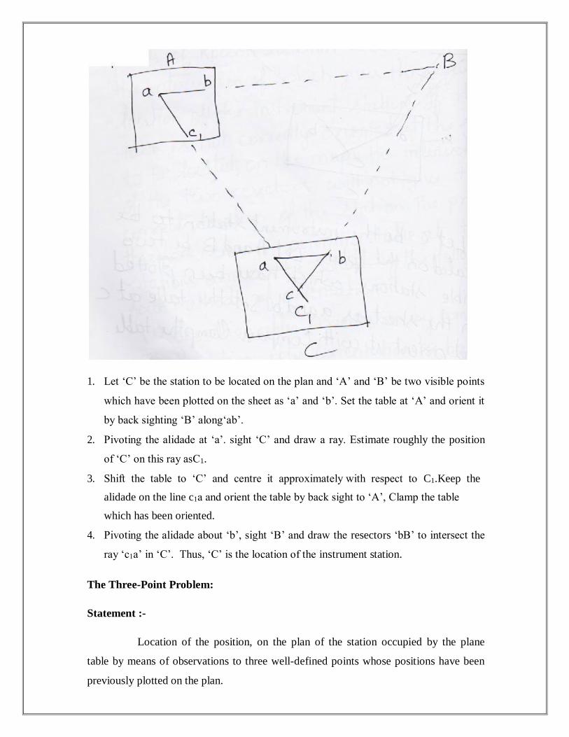
1. Let „C‟ be the station to be located on the plan and „A‟ and „B‟ be two visible points
which have been plotted on the sheet as „a‟ and „b‟. Set the table at „A‟ and orient it
by back sighting „B‟ along„ab‟.
2. Pivoting the alidade at „a‟. sight „C‟ and draw a ray. Estimate roughly the position
of „C‟ on this ray asC1.
3. Shift the table to „C‟ and centre it approximately with respect to C1.Keep the
alidade on the line c1a and orient the table by back sight to „A‟, Clamp the table
which has been oriented.
4. Pivoting the alidade about „b‟, sight „B‟ and draw the resectors „bB‟ to intersect the
ray „c1a‟ in „C‟. Thus, „C‟ is the location of the instrument station.
The Three-Point Problem:
Statement :-
Location of the position, on the plan of the station occupied by the plane
table by means of observations to three well-defined points whose positions have been
previously plotted on the plan.

The following are some of the important methods available for the solution
of the problem.
(a) Mechanical Method (Tracing Paper Method)
(b) Graphical Method
(c) Lehmann‟s Method (Trial and Error Method)
(a) Mechanical Method (Tracing Paper method)
The method involves the use of a tracing paper and is, therefore also known
as tracing paper method.
Procedure :
Let A, B, C be the known points and a, b, c be their plotted positions. Let „P‟
be the position of the instrument station to be located on the map.
(1) Set the table on P. Orient the table approximately with eye so that „ab‟ is
parallel to AB.
(2) Fix a tracing paper on the sheet and mark on it P‟ as the approximately location
of „P‟ with the help of plumbing fork.

(3) Pivoting the alidade at „P‟, sight A, B, C in turn and draw the corresponding
lines P‟a‟, P‟b‟ and P‟c‟ on the tracing paper. These lines will not pass through
a, b and c as the orientation is approximate.
(4) Loose the tracing paper and rotate it on the drawing paper in such a way that the
lines p‟a‟, p‟b‟ and p‟c‟ pass through a, b and c respectively. Transfer p‟ on to
the sheet and represent it as p. Remove the tracing paper and join pa, pb and pc.
(5) Keep the alidade on pa. The line of sight will not pass through „A‟ as the
orientation has not yet been corrected. To correct the orientation, loose the
clamp and rotate the plane table so that the line of sight passes through „A‟.
Clamp the table. The table is thus oriented.
(6) To test the orientation keep the alidade along pb. If the orientation is correct, the
line of sight will pass through B. similarly, the line of sight will pass through
„C‟ when the alidade is kept on pc.
Lehmann’s Method:-
This is the easiest and quickest solution. The principles of the method are as
follows:
(a) When the board is properly oriented and the alidade sighted to each control
signals A, B and C, rays drawn from their respective signals will interest at a
unique point.
(b) When rays are drawn from control signals, the angles of their intersections are
true angles whether or not the board is properly oriented.
Procedure :-
1. Set the table over new station p and approximately orient it.
2. With alidade on a sight A, similarly sight B and C. The three rays Aa, Bb and
Cc will meet at a point if the orientation is correct. Usually, however, they will
not meet but will form a small triangle known as the triangle of error.
3. To reduce the triangle of error to zero, another point „p‟ is chosen as per
Lehmann‟s rule.
4. Keep the alidade along p‟a and rotate the table to sight A. Clamp the table. This
will give next approximate orientation (but more accurate than the previous one).

Then sight „B‟ with alidade at b and „C‟ with alidade at c. The rays will again
form a triangle of error but much smaller.
5. The method has to be repeated till the triangle of error reduces to zero.
Lehmann’s Rules :-
There are three rules to help in proper choice of the point p‟.
1. If the plane table is set up in the triangle formed by the three points (i.e. p lies
within the triangle ABC) then the position of the instrument on the plan will be
inside the triangle of error, if not it will be outside.
2. The point P‟ should be so chosen that its distance from the rays Aa, Bb and Cc is
proportional to the distance of p from A, B and C respectively. Since the
rotation of the table must have the same effect on each ray.
3. The point p‟ should be so chosen that it lies either to the right of all three rays or
to the left of all three rays, since the table is rotated in one direction to locate P.
Referring to the figure below :
By rule 1 p is outside the small triangle as p is outside the triangle ABC.
By rule 2, using the proportions for the perpendiculars given by scaling the
distances PA, PB and PC, it must be in the left hand sector as shown.
By rule 3, it cannot be in either of the sectors contained by the rays PA, PB
and PC.

Indeterminate solution if point occupied at the circum circle of the three
control points :-
Alternative Graphical Solution :-
(1) Draw a line „ae‟ perpendicular to „ab‟ at „a‟. Keep the alidade a long „ea‟ and
rotate the plane Table till „A‟ is bisected. Clamp the table with „b‟ as centre, direct
the alidade to sight B and draw the ray be to cut „ae‟ in „e‟ Fig 28.1(a)
(2) Similarly, draw „cf‟ perpendicular to „bc‟ at „c‟. Keep the alidade along „FC‟ and
rotate the plane table till „c‟ is bisected clamp the table. With „b‟ as centre, direct
the alidade to sight „B‟ and draw the ray „bf‟ to cut „cf‟ in F Fig 28.1(b)
(3) Join „e‟ and „F‟. Using a set set square, draw „bp‟ perpendicular to „ef‟. Then „p‟
represents on the plane the position „p‟ of the table on the ground.
(4) To orient the table, keep the alidade along „pb‟ rotate the plane table till „B‟ is
bisected. To check the orientation draw rays aA, cC both of which should pass
through „p‟ as shown in Fig. 28.1(c).
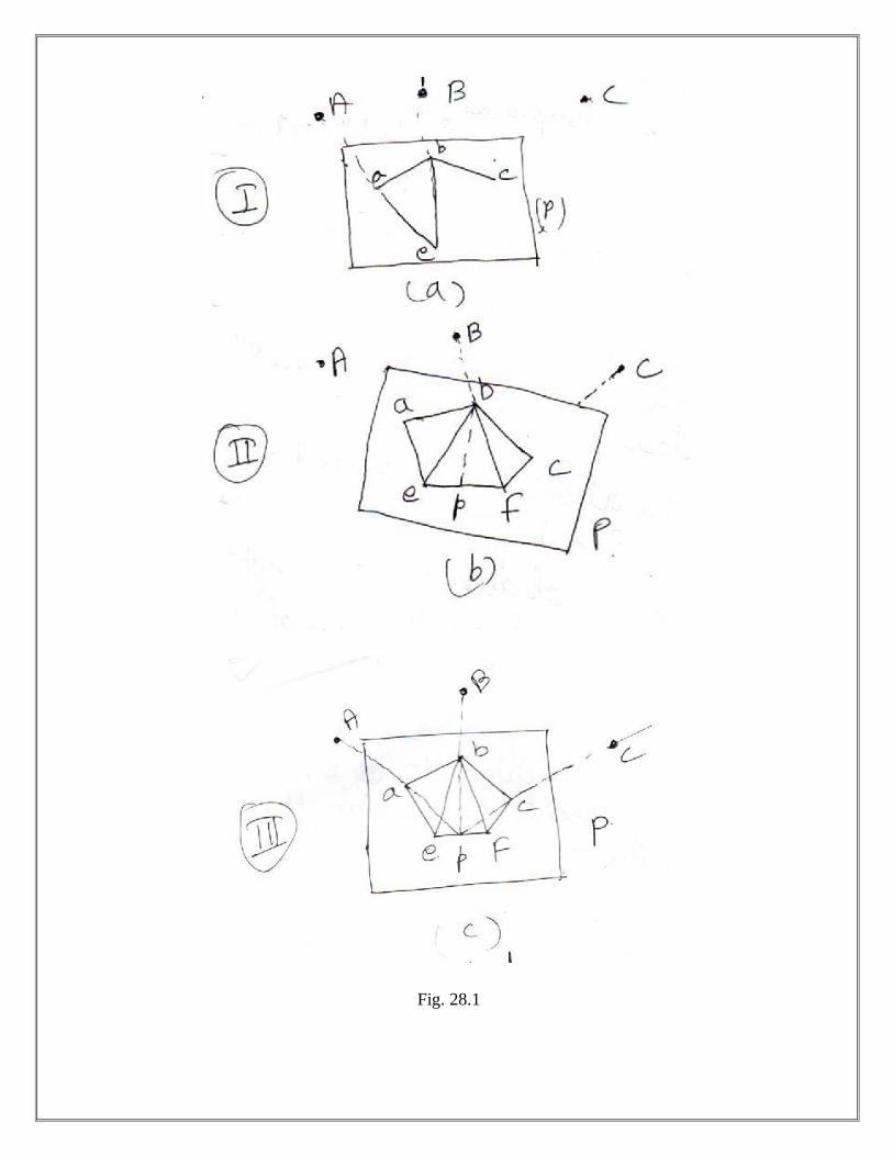
Fig. 28.1

Graphical Method :-
There are several graphical methods available, but the method given by
Bessel is more suitable and is described first.
Bessel’s Graphical Solution :-
(1) After having set the table at station „P‟, keep the alidade on „ba‟ and rotate the table
so that „A‟ is bisected. Clamp the table.
(2) Pivoting the alidade about „b‟, sight to „C‟ and draw the ray „xy‟ along the edge of
the alidade. [Fig28.2(a)]
(3) Keep the alidade along „ab‟ and rotate the table till „B‟ is bisected clamp the table.
(4) Pivoting the alidade about „a‟, sight to „C‟. Draw the ray along the edge of the
alidade to interest the ray „xy‟ in „cf‟. [Fig 28.2 (b)] Join cc‟.
(5) Keep the alidade along c‟c and rotate the table till „C‟ is bisected. Clamp the table.
The table is correctly oriented [Fig 28.2(c)].
(6) Pivoting the alidade about „b‟, sight to „B‟. Draw the ray to intersect cc‟ in „p‟.
Similarly, if alidade is pivoted about „a‟ and „A‟ is sighted, the ray will pass
through „p‟ if the work inaccurate.
Fig 28.2

Fig 28.2
The points a, b, c‟ and „p‟ form a quadrilateral and all the four points lie along the
circumference of a circle. Hence, this method is known as “Bessel‟s method of Inscribed
Quadrilateral”.
In the first four steps, the sightings for orientation was done through „a‟ and
„b‟ and rays were drawn, through „c‟. However, any two points may be used for
sighting and the rays drawn towards the third point, which is then sighted in steps 5 and
6.
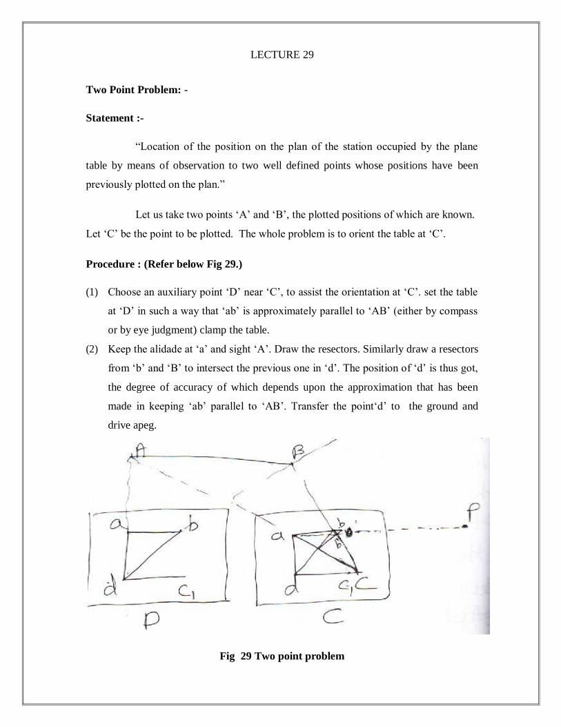
LECTURE 29
Two Point Problem: -
Statement :-
“Location of the position on the plan of the station occupied by the plane
table by means of observation to two well defined points whose positions have been
previously plotted on the plan.”
Let us take two points „A‟ and „B‟, the plotted positions of which are known.
Let „C‟ be the point to be plotted. The whole problem is to orient the table at „C‟.
Procedure : (Refer below Fig 29.)
(1) Choose an auxiliary point „D‟ near „C‟, to assist the orientation at „C‟. set the table
at „D‟ in such a way that „ab‟ is approximately parallel to „AB‟ (either by compass
or by eye judgment) clamp the table.
(2) Keep the alidade at „a‟ and sight „A‟. Draw the resectors. Similarly draw a resectors
from „b‟ and „B‟ to intersect the previous one in „d‟. The position of „d‟ is thus got,
the degree of accuracy of which depends upon the approximation that has been
made in keeping „ab‟ parallel to „AB‟. Transfer the point„d‟ to the ground and
drive apeg.
Fig 29 Two point problem

(3) Keep the alidade at „d‟ and sight „C‟. Draw the ray. Mark a point c1 on the ray by
estimation to represent the distance „DC‟.
(4) Shift the table to C, orient it (tentatively) by taking backside to „D‟ and centre it
with reference to c1. The orientation is, thus the same as it was at „D‟.
(5) Keep the alidade pivoted at „a‟ and sight it to „A‟. Draw the ray to interest with the
previously drawn ray from „D‟ in „c‟. thus, „c‟ is the point representing the station
C1 with reference to the approximate orientation made at „D‟.
(6) Pivoting the alidade about „c‟, sight „B‟. Draw the ray to intersect with the ray
drawn from „D‟ to „B‟ in b‟. Thus b‟ is the approximate representation of „B‟ with
respect to the orientation made at „D‟.
(7) The angle between ab and ab‟ is the error in orientation and must be corrected for.
So that „ab‟ and ab‟ may coincide (or may become parallel) keep a pole „P‟ in line
with ab‟ and at a great distance. Keeping the alidade along „ab‟, rotate the table till
„P‟ is bisected. Clamp the table. The table is thus correctly oriented.
(8) After having oriented the table as above, draw a resectors from „a‟ to „A‟ and
another from „b‟ to „B‟, the intersection of which will give the position „C‟
occupied by the table.
It is to be noted here that unless the point „P‟ is chosen infinitely distant, „ab‟
and ab‟ cannot be made parallel since the distance of „p‟ from „C‟ is limited due to other
considerations two-point problem does not give much accurate results. At the same
time, more labour is involved because the table is also to be set on one more station to
assist the orientation.

Unit 3
COMPUTATION OF AREAS AND VOLUMES
Introduction
Areas and Volumes are often required in the context of design, eg. We might need
the surface area of a lake, the area of crops, of a car park or a roof, the volume of a dam
embankment, or of a road cutting. Volumes are often calculated by integrating the area at
regular intervals eg. along a road centre line, or by using regularly spaced contours. We
simply use what you already know about numerical integration from numerical methods).
Objectives
After completing this topic you should be able to calculate the areas of polygons and
irregular figures and the volumes of irregular and curved solid
Triangles if s = (a + b + c) / 2 then area = S.(S-a)(S-b)(S-c)
Calculating area of a polygon from Coordinates: If the coordinate points are numbered
clockwise: area = 1 2 ∑ i=1 n ( Ni . Ei+1 - Ei . Ni+1 ) This formula is not easy to
remember, so let's look at a practical application
The computation of volumes of various quantities from the measurements done in the
field is required in the design and planning on many engineering works. The volume of
earth work is required for suitable alignment of road works, canal and sewer lines, soil
and water conservation works, farm pond and percolation pond consent. The computation
of volume of various materials such as coal, gravel and is required to check the stock
files, volume computations are also required for estimation of capacities of bins tanks etc.
For estimation of volume of earth work cross sections are taken at right angles to a fixed
line, which runs continuously through the earth work. The spacing of the cross sections
will depend upon the accuracy required. The volume of earth work is computed once the

various cross-sections are known, adopting Prismoidal rule and trapezoidal rule.

Volumes can be calculated in a number of ways. It is common to calculate the area of
each of several equally spaced slices (either vertical cross-sections, or horizontal
contours), and integrate these using Simpson's Rule or similar. A second method is to use
spot levels, and calculate the volume of a series of wedges or square cells. Cross-sections
are well suited for calculating volumes of roads, pipelines, channels, dam embankments,
etc. Formulae are given below for the most common cross-section cases.
Computation of area using different methods


Midpoint-ordinate rule
The rule states that if the sum of all the ordinates taken at midpoints of each division
multiplied by the length of the base line having the ordinates (9 divided by number of
equal parts).

The following perpendicular offsets were taken at 10m interval from a survey line to an
irregular boundary line. The ordinates are measured at midpoint of the division are 10, 13,
17, 16, 19, 21, 20 and 18m. Calculate the are enclosed by the midpoint ordinate rule.
Given:
Ordinates
O1 = 10
O2 = 13
O3 = 17
O4 = 16
O5 = 19
O6 = 21
O7 = 20
O8 = 18
Common distance, d =10m
Number of equal parts of the baseline, n = 8
Length of baseline, L = n *d = 8*10 = 80m
Area = [(10+13+17+16+19+21+20+18)*80]/8
Average Ordinate Rule
The rule states that (to the average of all the ordinates taken at each of the division of
equal length multiplies by baseline length divided by number of ordinates)
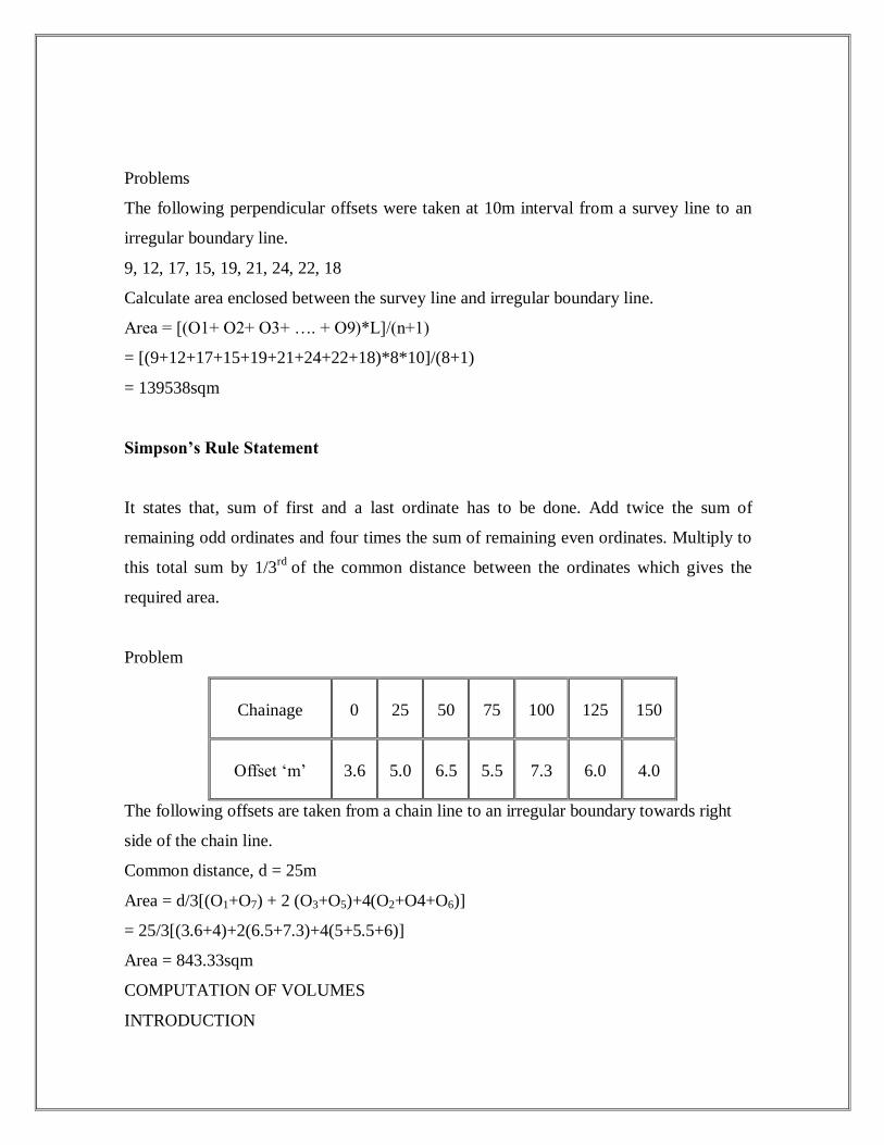
Problems
The following perpendicular offsets were taken at 10m interval from a survey line to an
irregular boundary line.
9, 12, 17, 15, 19, 21, 24, 22, 18
Calculate area enclosed between the survey line and irregular boundary line.
Area = [(O1+ O2+ O3+ …. + O9)*L]/(n+1)
= [(9+12+17+15+19+21+24+22+18)*8*10]/(8+1)
= 139538sqm
Simpson’s Rule Statement
It states that, sum of first and a last ordinate has to be done. Add twice the sum of
remaining odd ordinates and four times the sum of remaining even ordinates. Multiply to
this total sum by 1/3rd
of the common distance between the ordinates which gives the
required area.
Problem
Chainage 0 25 50 75 100 125 150
Offset „m‟ 3.6 5.0 6.5 5.5 7.3 6.0 4.0
The following offsets are taken from a chain line to an irregular boundary towards right
side of the chain line.
Common distance, d = 25m
Area = d/3[(O1+O7) + 2 (O3+O5)+4(O2+O4+O6)]
= 25/3[(3.6+4)+2(6.5+7.3)+4(5+5.5+6)]
Area = 843.33sqm
COMPUTATION OF VOLUMES
INTRODUCTION

The computation of volumes of various quantities from the measurements done in the
field is required in the design and planning on many engineering works. The volume of
earth work is required for suitable alignment of road works, canal and sewer lines, soil
and water conservation works, farm pond and percolation pond consent. The computation
of volume of various materials such as coal, gravel and is required to check the stock
files, volume computations are also required for estimation of capacities of bins tanks etc.
For estimation of volume of earth work cross sections are taken at right angles to a fixed
line, which runs continuously through the earth work. The spacing of the cross sections
will depend upon the accuracy required. The volume of earth work is computed once the
various cross-sections are known, adopting Prismoidal rule and trapezoidal rule
Problem
Compute the cost of earth work involved in cutting open a trench of following size.
Length 200 m, side slope 2: 1, depth of trench 4 m, bottom, width of trench 1.5 m. Cost of
earth work Rs. 50 per m3 . Cross sectional area of trench, A = (b + sh)*h
A = (1.5 + 2*4)*4 A = 9.5 * 4 = 38 m2
∴ Volume of earth work, V = A*L = 38 * 200 = 7600 m3
∴ Cost of earth work = 7600 * 50 = Rs. 3,80,000.00
Compute the volume of earth work involved in constructing a farm pond of the following
size: size, at bottom 6 x 4 m. Side slope 2: 1, depth of pond 4 m work out the cost of earth
work also if it costs Rs. 50 per cubic metre.

An embankment of width 10 m and side slopes 1 ½:1 is required to be made on a ground
which is level in a direction transverseto the centre line. The central heights at 40 m
intervals are as follows:
0.90,1.25,2.15,2.50,1.85,1.35, and 0.85
Calculate the volume of earth work according to
i) Trapezoidal formula
ii) Prismoidal formula


A level section, two level section and respective problems
Measurement of Volume of Earth work from Cross-Sections
The length of the project along the centre line is divided into a series of solids
known as Prismoidal by the planes of cross-sections. The spacing of the sections should
depend upon the character of ground and the accuracy required in measurement. They are
generally run at 20m or 30m intervals, but sections should also be taken at points of
change from cutting to filling, if these are known, and at places where a marked change of
slop occurs either longitudinally or transversely. The areas of the cross-sections which
have been taken are first calculated and the volumes of the Prismoidal between successive
cross- sections are then obtained by using the Trapezoidal formula or the Prismoidal
formula. The former is used in the preliminary estimates and for ordinary results, while
the latter is employed in the final estimates and for precise results. The Prismoidal
formula can be used directly or indirectly. In the indirect method, the volume is firstly
calculated by trapezoidal formula and the Prismoidal correction is then applied to this
volume so that the corrected volume is equal to that as if it has been calculated by
applying the Prismoidal formula directly. The indirect method being simpler is more

commonly used.
When the centre line of the project is curved in plan, the effect of curvature is also taken
into account specially in final estimates of earthwork where much accuracy is needed. It is
the common practice to calculate the volumes as straight as mentioned above and then to
apply the correction for curvature to them.
Another method of finding curved volumes is to apply the correction for curvature to the
areas of cross-sections, and then to compute the required volumes from the corrected
areas from Prismoidal formula
The following are the various cross-sections usually met with whose areas are to be
computed:
1. Level section.
2. Two-level section.
3. Side-hill two-level section.
4. Three-level section.
5. Multi-level section


Formula
Let Σ F= sum of the product of the co-ordinates joined by full lines.
Σ D= sum of the products of the co-ordinates joined by dotted lines.
Then, A= 1/2 (ΣF- ΣD)
Volume of a reservoir
Formulae for volume:
• To calculate die volumes of the solids between sections, it must be assumed that
they have some geometrical from. They must nearly take the form of Prismoidal
and therefore, in calculation work, they are considered to be Prismoidal.
• Let A1, A2, A3…………….. An = the areas at the 1st, 2nd, 3rd……………… last
cross-section.
• D = the common distance between the cross-section.
V = the volume of cutting or filling
Measurement of Volumes from contours:
• Mass Diagram:
• The mass diagram is a graph plotted between distances along centre line, taken as
base and algebraic sum of the mass of the earth work, taken as ordinates. The
volume of cutting is considered as positive where as that of filling as negative.
For determining in advance, the proper distribution of excavated material and the
amount of waste and borrow, a mass diagram is commonly used. From the mass
diagram, it is possible to determine by trial, the earthwork distribution plan that
will result in the minimum cost of overhaul and the economical expenditure for
overhaul and borrow
Lift and Lead:
• Lift:
• Vertical distance through which the excavated earth is lifted beyond a certain
depth is called lift. Excavation up to 1.5m depth below ground level and excavated
material deposited on the ground shall be included in the item of work as
specified. The lift shall be measured from the C.G. of the excavated earth to that
of the deposited earth. Extra lift shall be measured in unit of 1.5m or as per pre-
accepted condition.
• Lead:

• The horizontal distance from borrow pit to the site of work is called lead. It shall
be measured from the centre of the area of excavation to the centre of the placed
earth. Normally a lead up to 30m or as per pre- accepted condition is not paid-
extra.
Beyond a lead of 30m and lift of 1.5m rates will be different for every unit of 30m
lead and 1.5m lift or fraction thereof
Converting Lift into lead:
• The lift is converted into lead by the following rules:
• 1. The lift up to 3 .6m is multiplied by 10
• 2. Lift more than 3.6m and less than 6m is squared and multiplied by 3.3.
Lift more than 6m is multiplied by 20
THEODOLITE AND TRAVERSE SURVEYING
Types of Theodolite
There are two different kinds of Theodolite: digital and non digital. Non digital
Theodolite are rarely used anymore. Digital Theodolite consists of a telescope that is
mounted on a base, as well as an electronic readout screen that is used to display
horizontal and vertical angles. Digital Theodolite are convenient because the digital
readouts take the place of traditional graduated circles and this creates more accurate
readings.
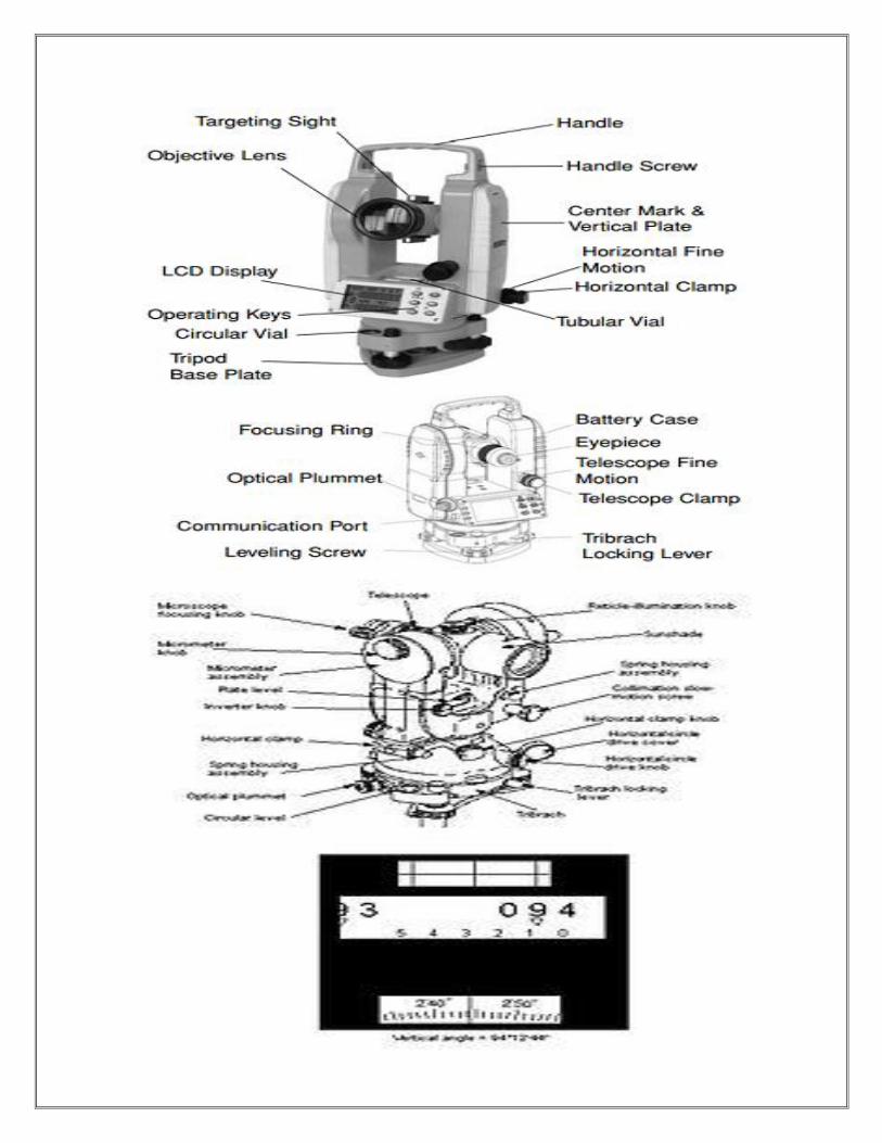

How Does a Theodolite Work
A Theodolite works by combining optical plummets (or plumb bobs), a spirit (bubble
level), and graduated circles to find vertical and horizontal angles in surveying. An optical
plummet ensures the Theodolite is placed as close to exactly vertical above the survey
point. The internal spirit level makes sure the device is level to the horizon. The graduated
circles, one vertical and one horizontal, allow the user to actually survey for angles
• Theodolite are mainly used for surveying, but they are also useful in these
applications:
• Navigating
• Meteorology
• Laying out building corners and lines
• Measuring and laying out angles and straight lines
• Aligning wood frame walls
• Forming panels
• Plumbing a column or building corner
Terminology of Theodolite It is important to clearly understand the terms associated with the Theodolite and its use
and meaning. The following are some important terms and their definitions.
Vertical axis
It is a line passing through the centre of the horizontal circle and perpendicular to it.
The vertical axis is perpendicular to the line of sight and the trunnion axis or the
horizontal axis. The instrument is rotated about this axis for sighting different points
Horizontal axis
It is the axis about which the telescope rotates when rotated in a vertical plane. This
axis is perpendicular to the line of collimation and the vertical axis.
Telescope axis It is the line joining the optical centre of the object glass to the centre of
the eyepiece
Line of collimation
It is the line joining the intersection of the cross hairs to the optical centre of the object
glass and its continuation. This is also called the line of sight.
Axis of the bubble tube
It is the line tangential to the longitudinal curve of the bubble tube at its centre

Unit-5
Tacheometric and advanced surveying It is a method of angular surveying in which the horizontal distance from the
instrument to the staff stations and the elevations of the staff stations concerning the
line of collimation of the instrument are determined from instrumental observations
only
• Thus the chaining operations are eliminated. Field Work can be completed very
rapidly Tachometry is mainly used for preparing the contour plans of areas
Methods of Tachometric Survey • Various methods of tachometry survey are based on the principle that the
horizontal distance between an instrument Station “A” and a staff station “B” and
the elevation of point “B” with reference to the line of sight of the instrument at
point “A” depend on the angle subtended at point “A” by a known distance at
point “B” and the vertical angle from point “B” to point “A” respectively.
• This principle is used in different methods in different ways. Mainly there are two
methods of tachometry survey
(1)Stadia system, and
(2) Tangential system
Stadia System of Tachometry;
In the stadia system, the horizontal distance to the staff Station from the
instrument station and the elevation of the staff station concerning the line of sight
of the instrument is obtained with only one observation from the instrument
Station
• In the stadia method, there are mainly two systems of surveying.
• (1) fixed hair method and,
• (2) Movable hair method.
• (i) Fixed Hair Method:
In the fixed hair method of tachometric surveying, the instrument employed for
taking observations consist of a telescope fitted with two additional horizontal
cross hairs one above and the other below the central hair. These are placed
equidistant from the central hair and are called stadia hairs
• When a staff is viewed through the telescope, the stadia hairs are seen to intercept
a certain length of the staff and this varies directly with the distance between the
instrument and the stations.
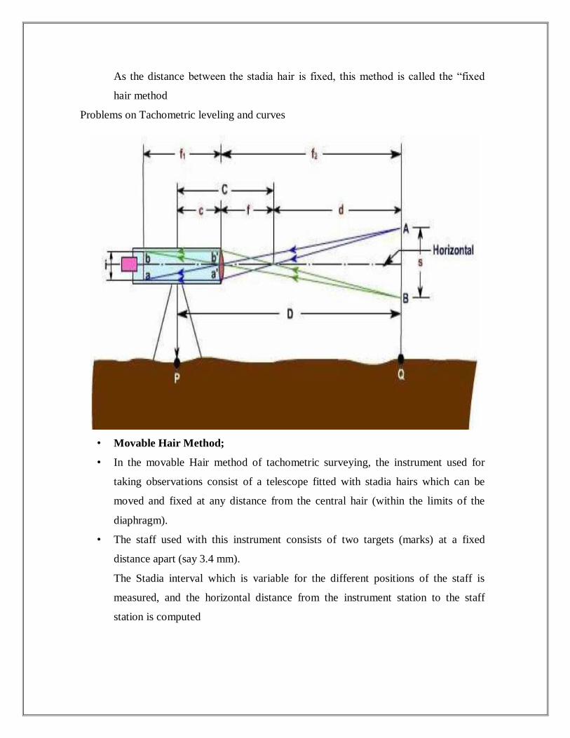
As the distance between the stadia hair is fixed, this method is called the “fixed
hair method
Problems on Tachometric leveling and curves
• Movable Hair Method;
• In the movable Hair method of tachometric surveying, the instrument used for
taking observations consist of a telescope fitted with stadia hairs which can be
moved and fixed at any distance from the central hair (within the limits of the
diaphragm).
• The staff used with this instrument consists of two targets (marks) at a fixed
distance apart (say 3.4 mm).
The Stadia interval which is variable for the different positions of the staff is
measured, and the horizontal distance from the instrument station to the staff
station is computed

Tangential System of Tacheometric Surveying:
In this system of tachometric surveying, two observations will be necessary from
the instrument station to the staff station to determine the horizontal distance and
the difference in the elevation between the line of collimation and the staff station

ADVANCED SURVEYING