Survey of Software Assurance Techniques for Highly ... · NASA/CR-2004-212805 Survey of Software...
67
NASA/CR-2004-212805 Survey of Software Assurance Techniques for Highly Reliable Systems Stacy Nelson February 2004 https://ntrs.nasa.gov/search.jsp?R=20040034185 2018-08-08T13:55:14+00:00Z
Transcript of Survey of Software Assurance Techniques for Highly ... · NASA/CR-2004-212805 Survey of Software...

NASA/CR-2004-212805
Survey of Software Assurance Techniques for HighlyReliable Systems
Stacy Nelson
February 2004
https://ntrs.nasa.gov/search.jsp?R=20040034185 2018-08-08T13:55:14+00:00Z

Since its founding, NASA has been dedicated to theadvancement of aeronautics and space science. TheNASA Scientific and Technical Information (STI)Program Office plays a key part in helping NASAmaintain this important role.
The NASA STI Program Office is operated byLangley Research Center, the Lead Center forNASA’s scientific and technical information. TheNASA STI Program Office provides access to theNASA STI Database, the largest collection ofaeronautical and space science STI in the world.The Program Office is also NASA’s institutionalmechanism for disseminating the results of itsresearch and development activities. These resultsare published by NASA in the NASA STI ReportSeries, which includes the following report types:
• TECHNICAL PUBLICATION. Reports ofcompleted research or a major significant phaseof research that present the results of NASAprograms and include extensive data or theoreti-cal analysis. Includes compilations of significantscientific and technical data and informationdeemed to be of continuing reference value.NASA’s counterpart of peer-reviewed formalprofessional papers but has less stringentlimitations on manuscript length and extentof graphic presentations.
• TECHNICAL MEMORANDUM. Scientific andtechnical findings that are preliminary or ofspecialized interest, e.g., quick release reports,working papers, and bibliographies that containminimal annotation. Does not contain extensiveanalysis.
• CONTRACTOR REPORT. Scientific andtechnical findings by NASA-sponsoredcontractors and grantees.
The NASA STI Program Office . . . in Profile
• CONFERENCE PUBLICATION. Collectedpapers from scientific and technical confer-ences, symposia, seminars, or other meetingssponsored or cosponsored by NASA.
• SPECIAL PUBLICATION. Scientific, technical,or historical information from NASA programs,projects, and missions, often concerned withsubjects having substantial public interest.
• TECHNICAL TRANSLATION. English-language translations of foreign scientific andtechnical material pertinent to NASA’s mission.
Specialized services that complement the STIProgram Office’s diverse offerings include creatingcustom thesauri, building customized databases,organizing and publishing research results . . . evenproviding videos.
For more information about the NASA STIProgram Office, see the following:
• Access the NASA STI Program Home Page athttp://www.sti.nasa.gov
• E-mail your question via the Internet [email protected]
• Fax your question to the NASA Access HelpDesk at (301) 621-0134
• Telephone the NASA Access Help Desk at(301) 621-0390
• Write to:NASA Access Help DeskNASA Center for AeroSpace Information7121 Standard DriveHanover, MD 21076-1320

NASA/CR-2004-212805
Survey of Software Assurance Techniques for HighlyReliable Systems
Stacy NelsonAmes Research Center, Moffett Field, California
February 2004
National Aeronautics andSpace Administration
Ames Research CenterMoffett Field, California 94035-1000

Available from:
NASA Center for AeroSpace Information National Technical Information Service7121 Standard Drive 5285 Port Royal RoadHanover, MD 21076-1320 Springfield, VA 22161(301) 621-0390 (703) 487-4650

Survey of Software Assurance Techniques for Highly Reliable Systems Prepared by: Stacy Nelson August 27, 2003
Ames Research Center Moffett Field, California
Jet Propulsion Laboratory Pasadena, California

Survey of Software Assurance Techniques for Highly Reliable Systems Page 2
TABLE OF CONTENTS 1 EXECUTIVE SUMMARY......................................................................................................................4 2 SUMMARY OF TECHNIQUES ............................................................................................................7
2.1 Accepted V&V Techniques..........................................................................................................7 2.2 Other Techniques ......................................................................................................................10 2.3 Artificial Intelligence ...................................................................................................................10
3 INTRODUCTION................................................................................................................................11 4 WHY STANDARDS?..........................................................................................................................12
4.1 Comparison of SEI SW-CMM, ISO 9001 with ISO 9000-3 and IEC SILs17...............................13 4.2 Comparison of SEI SW-CMM and DO-178B.............................................................................14
5 AEROSPACE INDUSTRY..................................................................................................................15 5.1 FAA Safety-Critical Certification Techniques.............................................................................15 5.2 DFRC Intelligent Flight Control System (IFCS) .........................................................................17 5.3 NASA Software Assurance Standards ......................................................................................19 5.4 NASA ARC Deep Space One....................................................................................................23 5.5 DS1 Formal V&V of Remote Agent 13........................................................................................27 5.6 NASA Space Shuttle25 ...............................................................................................................30
6 DEFENSE INDUSTRY .......................................................................................................................35 6.1 Military Standards ......................................................................................................................35 6.2 Wearable Computers.................................................................................................................38 6.3 MIL-STD-882D...........................................................................................................................39 6.4 DEF STAN 00-55.......................................................................................................................40
7 NUCLEAR POWER INDUSTRY17......................................................................................................42 8 MEDICAL DEVICES INDUSTRY .......................................................................................................45 9 TRANSPORTATION INDUSTRY14 ....................................................................................................47 10 APPENDIX A - SOFTWARE INTEGRITY LEVELS (SILs).................................................................55 11 APPENDIX B – SAFETY CASE.........................................................................................................56 12 DEFINITIONS and ACRONYMS........................................................................................................57
12.1 Definitions ..................................................................................................................................57 12.2 Acronyms...................................................................................................................................60
13 REFERENCES...................................................................................................................................61
August 27, 2003
Survey of Software Assurance Techniques for Highly Reliable Systems Page 3
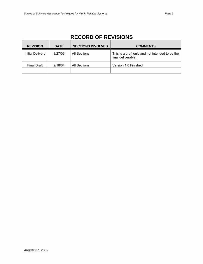
RECORD OF REVISIONS REVISION DATE SECTIONS INVOLVED COMMENTS
Initial Delivery
8/27/03
All Sections This is a draft only and not intended to be the final deliverable.
Final Draft 2/18/04 All Sections Version 1.0 Finished
August 27, 2003

Survey of Software Assurance Techniques for Highly Reliable Systems Page 4
1 EXECUTIVE SUMMARY Software plays an increasing crucial role in all aspects of modern life from flight to driving to power generation to weapons to medical devices, etc. Therefore, we must be able to trust that software is reliable and will act according to intended design rather than exhibiting errant behaviors.
Highly Reliable Software Required
Transportation
Aerospace
Defense
Medical DevicesNuclear Power
Currently, key facets of reliable software depend upon trust and thoroughness of the software development process, called the software life cycle. Software life cycles vary across industries and across projects within the same industry, but the overall idea is the same: assemble a team of competent software developers to determine the intended software behaviors (requirements) then develop code to accomplish these behaviors. Submit the requirements and code to a team of verification and validation specialists who check them via a variety of techniques ranging from testing to simulation to formal methods.
Then this code is evaluated by an independent team of software development experts who review the software during formal review sessions to decide whether it meets its objectives. If the software is deemed safety critical (has potential for loss of life), the reviewers generally ask themselves whether they would be willing to use the software. They consider questions such as: Would I risk my life to fly on an airplane with this digital flight control system? Would I drive an automobile with anti-lock brakes? If the answer is yes then the software
is submitted for system certification. Generally, software does not receive a standalone certification. Only integrated components including hardware and software are certified. If the software is mission-critical (potential for loss of spacecraft, lab, mission data, etc) then reviewers consider whether test results indicate a significant likelihood of mission success. If yes, then the software is approved for implementation. Approving software is a difficult task. To make the approval decision, reviewers must believe, based on the facts presented, that the software has been thoroughly and rigorously checked.
August 27, 2003

Survey of Software Assurance Techniques for Highly Reliable Systems Page 5
This paper summarizes key processes used across industry and government in the United States and Europe to determine whether software is safe and reliable. These processes reveal the following common themes:
• Standards exist containing lessons learned from prior development projects to promote safer, more reliable software
• Review boards make decisions about the software safety and reliability based on trust in the development team, demonstration of key software capabilities in high-fidelity simulators and rigorous and thorough verification and validation (includes testing)
• Software sometimes fails despite best efforts to verify and validate capabilities
• Formal methods can uncover hard-to-find errors like race conditions
• Software reliability metrics generally consist of keeping track of the number of issues (bugs). For example, the Space Shuttle IV&V team computes the following metrics:
o Number of Issue Tracking Reports (ITRs) per software release
o Number of Days an ITR remained open – a measure of complexity
o Severity of Open and Closed ITRs
o Open ITRs by Severity Level The following techniques have proven to be necessary for developing safety-critical software across all industries:
• Testing based on key scenarios designed to check that software works as intended
• Simulation beginning on low fidelity testbeds and occurring on higher-fidelity testbeds until final tests occur on the actual hardware. This promotes cost containment by allowing developers to find and correct anomalies early in development before exposing expensive hardware to possible failures
• Demonstrations of working software to qualified review boards in accordance with industry standards. Certification or approval by review boards is consistent across all industries. Therefore, individual projects succeed or fail based on the aptitude of these review boards.
While ANSI/IEEE 982.1-1989 and 982.2-1989: Measures to Produce Reliable Software contain a plethora of metrics, review boards in the United States currently emphasize the following to determine whether software is safe and reliable:
• Test results
• Demonstration of software in high-fidelity testbeds
• Trust in the experience and expertise of the development and verification/validation teams
Review boards in Europe and Canada supplement reliance upon experienced teams and demonstrations with effective use of formal methods to prove software correctness properties.
Unfortunately, software errors still occur. According to the summary in Section 2, the following additional techniques (listed in alphabetical order) were used across at least three industries. The industries are noted in parentheses:
• Formal Methods (Canada and European nuclear power and transportation)
• Information Flow Analysis (aerospace, defense and nuclear power)
• Partitioning (aerospace, nuclear power and transportation)
August 27, 2003

Survey of Software Assurance Techniques for Highly Reliable Systems Page 6
• Risk/hazard assessment based on severity and likelihood (aerospace, defense and transportation)
The aerospace, nuclear power and transportation industries rely upon Fault Detection and Diagnosis as a safety net to respond in the event of an unforeseen error resulting from either V&V oversight or unexpected environmental conditions.
To supplement the traditional life cycle, the FAA and SAE recommend building safety or reliability case (justification) as part of software development.
As software becomes more sophisticated, more software failures are likely. The following advanced techniques (listed in alphabetical order) have been used in experiments (NASA, industry and academia) to improve verification and validation of highly reliable software with promising results:
• Architecture Design and Analysis (LTSA, ACME, Rapide)
• Automated test case generation
• Automated test data and test data vector generation
• Automatic Code Generation (Rhapsody, Matlab/Simulink)
• Model Checking (SPIN, SMV, FeaVer, Pathfinder, LPF)
• Requirements Definition Tools (UBET)
• Requirements Modeling and Analysis (PVS, Alloy, SCR, RSML)
• Runtime analysis (PathExplorer, Temporal Rover, Prospec)
• Static analysis (Coverity)
• Theorem proving (Certifiable Software Synthesis)
August 27, 2003

Survey of Software Assurance Techniques for Highly Reliable Systems Page 7
2 SUMMARY OF TECHNIQUES This section summarizes techniques and measures accepted across industry for development of safety-critical and embedded, real-time mission-critical software. It contains three sections:
• Accepted V&V Techniques
• Other Techniques
• Artificial Intelligence
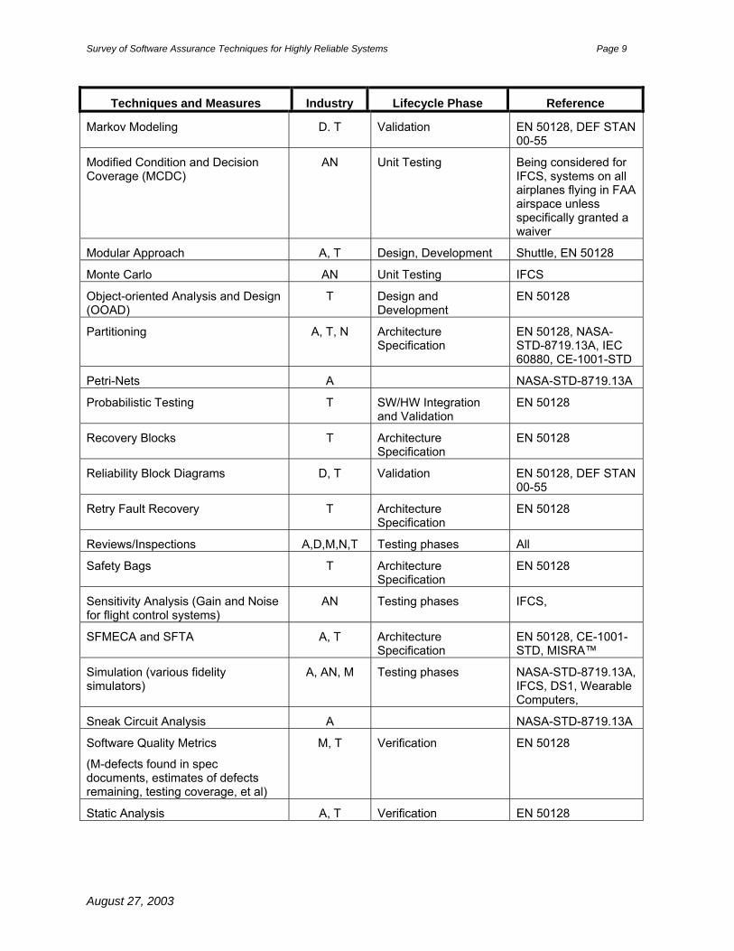
2.1 Accepted V&V Techniques The following table summarizes V&V techniques and measures. It lists the technique, industry code (A- Aerospace for spacecraft with subcategory AN- Aeronautical for aircraft, D-Defense, N-Nuclear Power, M-Medical Devices, T-Transportation), general life cycle phase or phases and reference to the standard or project supporting the technique. Table 1: Techniques Used Across Industries Developing Safety-Critical Software
Techniques and Measures Industry Lifecycle Phase Reference
Automated Regression Testing A, AN, D, Testing IFCS, DS1, Wearable Computers
Cause Consequence Diagrams D, T Validation EN 50128, DEF STAN 00-55
Checklists T Validation EN 50128
Common Cause Failure Analysis D, T Validation EN 50128, DEF STAN 00-55
Control Flow Analysis A, D NASA-STD-8719.13A, DEF STAN 00-55
Data checked by plausibility checks, reasonableness checks, parameter type verification and range check on input variables, output variables, intermediate parameters and array bounds.
N Unit testing IEC 60880
Data Recording and Analysis T, D Design, Development and Maintenance
EN 50128, DEF STAN 00-55
Defensive Programming T Architecture Specification
EN 50128
Defensive Programming, Defense in Depth
T, N Architecture Specification
EN 50128, IEC 60880
Design and coding standards T Design, Development and Maintenance
EN 50128
Diverse Programming T Architecture Specification
EN 50128
Dynamic Analysis (Runtime Monitoring)
T Verification EN 50128
August 27, 2003

Survey of Software Assurance Techniques for Highly Reliable Systems Page 8
Techniques and Measures Industry Lifecycle Phase Reference
Dynamic Reconfiguration (neural networks)
AN Architecture Specification
IFCS
Ensure arrays have fixed, predefined length
N Unit testing IEC 60880
Ensure branches in case statement should be exhaustive and preferably mutually exclusive
N Unit testing IEC 60880
Ensure constants and variables separated in memory
N Unit testing IEC 60880
Ensure no more than 50-100 executable lines per module
N Unit testing IEC 60880
Error Detection A, T Architecture Specification
EN 50128
Event Tree Analysis T Validation EN 50128
Failure Assertion A, T Architecture Specification
EN 50128
Fault Detection and Diagnosis A, N, T Architecture Specification
DS1, EN 50128, IEC 60880, MISRA™
Field Trials T Validation EN 50128
FMECA and FTA A, D, N, T Architecture Specification
EN 50128, NASA-STD-8719.13A, DEF STAN 00-55, CE-1001-STD, MISRA™
Formal Methods - Model Checking A (experimental)
Design and testing phases
DS1
Formal Methods (CCS, CSP, HOL, LOTOS, OBJ, Temporal Logic, VDM, Z, formal specification…)
A, T, N Requirements, Specification, Design, Development and Verification
DS1, EN 50128, IEC 60880
Formal Proofs D, N Requirements phases DEF STAN 00-55, CE-1001-STD
Ground-based twin software to mirror onboard software
A Testing phases DS1
Hierarchy Analysis A NASA-STD-8719.13A
Independence (different teams developing different algorithms)
A All NASA-STD-8719.13A
Independence between development and test teams
A, N Testing phases Shuttle, CE-1001-STD
Information Flow Analysis A, D, N NASA-STD-8719.13A, DEF STAN 00-55, CE-1001-STD
August 27, 2003
Survey of Software Assurance Techniques for Highly Reliable Systems Page 9
Techniques and Measures Industry Lifecycle Phase Reference
Markov Modeling D. T Validation EN 50128, DEF STAN 00-55
Modified Condition and Decision Coverage (MCDC)
AN Unit Testing Being considered for IFCS, systems on all airplanes flying in FAA airspace unless specifically granted a waiver
Modular Approach A, T Design, Development Shuttle, EN 50128
Monte Carlo AN Unit Testing IFCS
Object-oriented Analysis and Design (OOAD)
T Design and Development
EN 50128
Partitioning A, T, N Architecture Specification
EN 50128, NASA-STD-8719.13A, IEC 60880, CE-1001-STD
Petri-Nets A NASA-STD-8719.13A
Probabilistic Testing T SW/HW Integration and Validation
EN 50128
Recovery Blocks T Architecture Specification
EN 50128
Reliability Block Diagrams D, T Validation EN 50128, DEF STAN 00-55
Retry Fault Recovery T Architecture Specification
EN 50128
Reviews/Inspections A,D,M,N,T Testing phases All
Safety Bags T Architecture Specification
EN 50128
Sensitivity Analysis (Gain and Noise for flight control systems)
AN Testing phases IFCS,
SFMECA and SFTA A, T Architecture Specification
EN 50128, CE-1001-STD, MISRA™
Simulation (various fidelity simulators)
A, AN, M Testing phases NASA-STD-8719.13A, IFCS, DS1, Wearable Computers,
Sneak Circuit Analysis A NASA-STD-8719.13A
Software Quality Metrics
(M-defects found in spec documents, estimates of defects remaining, testing coverage, et al)
M, T Verification EN 50128
Static Analysis A, T Verification EN 50128
August 27, 2003

Survey of Software Assurance Techniques for Highly Reliable Systems Page 10
Techniques and Measures Industry Lifecycle Phase Reference
Structured methodologies (JSD, MASCOT, SADT, SDL, SSADM, Yourdon)
T Requirements, Specification, Design and Development
EN 50128
Telemetry testing A Testing phases DS1
Testing – Functional testing including Operational Scenarios and Performance testing
A,D,M,N,T Testing phases All
A- Aerospace for spacecraft with subcategory AN- Aeronautical for aircraft, D-Defense, N-Nuclear Power, M-Medical Devices, T-Transportation Note: This list is not intended to be comprehensive, but is based on review of industry standards conducted within the time allotted by the Mars Science Laboratory (MSL) mission and personal project/mission experience.
2.2 Other Techniques The following table summarizes other techniques. It lists the technique, industry code (A- Aerospace, D-Defense, N-Nuclear Power, M-Medical Devices, T-Transportation), activity and reference to the standard or project supporting the technique. Table 2: Other Techniques
Techniques and Measures Industry Activity Reference
Change Impact Analysis T Maintenance EN 50128
Hazard reports A, D Risk Assessment NASA-STD-8719.13A MIL-STD-882D, DEF STAN 00-55
Risk Assessment A, M, D, T Risk Assessment NASA-STD-8719.13A, MIL-STD-882D, IEC 601-1-4, EN 50126
Software Reliability Plan and Case T Software Reliability SAE JA 1002 A- Aerospace, D-Defense, N-Nuclear Power, M-Medical Devices, T-Transportation Note: This list is not intended to be comprehensive, but is based on review of industry standards conducted within the time allotted by the Mars Science Laboratory (MSL) mission and personal project/mission experience.
2.3 Artificial Intelligence Artificial Intelligence software is not recommended by any industries although successful flight experiments have been conducted in the aerospace industry including Deep Space One and the Intelligent Flight Control System.
August 27, 2003
Survey of Software Assurance Techniques for Highly Reliable Systems Page 11
3 INTRODUCTION This document provides a survey of software assurance techniques for highly reliable systems including a discussion of relevant safety standards for various industries in the United States and Europe, as well as examples of methods used during software development projects. It contains one section for each industry surveyed.
Each section provides an overview of applicable standards and examples of a mission or software development project, software assurance techniques used and reliability achieved. It is organized as follows:
• Why Standards? – overview of key U. S. standards that govern software development and provide the basis for industry standards and comparison of Software Engineering Institute Software Capability Maturity Model (SW-CMM) to ISO 9001 with ISO 9000-3 and International Electro-technical Commission (IEC) Safety Integrity Levels (SILs)
• Aerospace Industry
o Overview of FAA enforced RTCA DO-178B Certification Standards
Discussion of NASA Dryden Flight Research Center (DRFC) Intelligent Flight Control System (IFCS) for F-15 (Collaboration with Boeing)
o Overview of NASA Safety Assurance Standards
Description of NASA Ames Research Center (ARC) Deep Space One (both traditional testing and formal methods experiments)
Description of NASA Space Shuttle
• Defense Industry
o Overview of MIL-STD 498
o Overview of MIL-STD-882D, Mishap Risk Management (System Safety)
o Overview of DEF STAN 00-55, Requirements for Safety Related Software in Defence Equipment Part 1: Requirements and Part 2: Guidance, U.K. Ministry of Defence.
o Description of Advanced Weapons System
• Nuclear Power Industry
o Overview of IEC 60880:1986-09, Software for Computers in Safety Systems of Nuclear Power Stations
o Overview of CE-1001-STD Rev. 1, Standard for Software Engineering of Safety Critical Software, CANDU Computer Systems Engineering Centre for Excellence, January 1996
• Medical Device Industry
o Overview of IEC 601-1-4
• Transportation Industry
o Overview of EN (European Norms) 50128:1997, Railway Applications: Software for Railway Control and Protection Systems, the European Committee for Electrotechnical Standardisation (CENELEC)
o Overview of Development Guidelines for Vehicle-Based Software, The Motor Industry Software Reliability Association (MISRA™), November 1994
o Overview of JA 1002 Software Reliability Program Standard, Society of Automotive Engineers (SAE), 1998
August 27, 2003

Survey of Software Assurance Techniques for Highly Reliable Systems Page 12
4 WHY STANDARDS?
In an effort to produce safe, reliable software, high-level standards have been written containing the lessons learned by trial and error on government and commercial software projects. They serve as a foundation to prevent known mistakes from being repeated and provide processes to help uncover unforeseen problems. These high-level standards have guidelines that can be tailored to address specific challenges faced by different industries. Specific industry standards are described in subsequent sections.
History of Key USA Standards
2167A
7935A
498
ISO 12207 IEEE Stds
IEEE/EIA12207016
DOD-STD-7935A “DoD Automated Information Systems (AIS) Documentation Standards”Oct 88
DOD-STD-2167A “Defense System Software Development”Feb 88
ISO/IEC 12207 “Software Life Cycle Processes” Aug 95
J-STD-016-1995(Trial Use)“Software Life Cycle Processes, Software Development” Sep 95
IEEE/EIA 12207.0-1996IEEE/EIA 12207.1-1997IEEE/EIA 12207.2-1997“Software Life Cycle Processes”Mar/Apr 98
MIL-STD-498“Software Development and Documentation” Dec 94
Introduction to IEEE/EIA 12207 presentation by Jim Wells
Figure 1: History of Key USA Standards1
Figure 1 depicts on overview of the history of key U. S. standards. Reading from left to right, DOD-STD 2167A and DOD-STD-7935A were combined to form MIL-STD 498 which is currently used for military software development. Information from ISO/IEC 12207 in combination with J-STD-016-1995 and various IEEE standards was updated and clarified in IEEE/EIA 12207. IEEE/EIA 12207 contains concepts and guidelines to foster better understanding and application. It is divided into three volumes:
• 12207.0 – Software Life Cycle Processes
• 12207.1 – Software Life Cycle Processes Life Cycle Data
• 12207.2 – Software Life Cycle Processes Implementation Considerations
Each of these U. S. Standards has at least one European counterpart.
August 27, 2003

Survey of Software Assurance Techniques for Highly Reliable Systems Page 13
4.1 Comparison of SEI SW-CMM, ISO 9001 with ISO 9000-3 and IEC SILs17 In addition to the standards, the Software Engineering Institute (SEI) Software Capability Maturity Model (SW-CMM) and ISO 9001 with ISO 9000-3 are two of the most well-known approaches to basic “good” software engineering practices. SW-CMM consists of five graded maturity levels representing more rigorous software engineering processes. The overall goal is defect prevention accomplished, in theory, through repeatable software engineering processes that produce a product of predictable quality. ISO 9001 with ISO 9000-3 roughly equates to SW-CMM level 2.5.
However, basic “good” software engineering practices do not address safety or reliability issues. These practices are geared toward commercial grade software that executes in an office environment. The emphasis is on functionality rather than safety. There is no provision for conducting hazard analyses or risk assessments. The criticality of software modules is generally not determined. There is no concept of designing a system to fail safe or fail operational to prevent hazardous consequences; instead it is assumed that the end user will simply reboot if their system crashes.
Therefore, the following table based on work by Debra Herrmann and Nancy Leveson provides a hypothetical relationship between SW-CMM and International Electro-technical Commission (IEC) Safety Integrity Levels (SIL):
5Optimizing
5Optimizing
4Managed
4Managed
3Defined
3Defined
2Repeatable
2Repeatable
1Initial/Chaos
1Initial/Chaos
SIL 4Very High
SIL 4Very High
SIL 3High
SIL 3High
SIL 2Medium SIL 2
Medium
SIL 1LOW
SIL 1LOW
0NONE
0NONE ISO 9001
ISO 9000-3ISO 9001
ISO 9000-3
SEI SW-CMM Levels
IEC Safety Integrity Levels
~= ~=
Figure 2: Hypothetical Relationship between CMM and SILs17
For more information on SILs, see Appendix A.
August 27, 2003

Survey of Software Assurance Techniques for Highly Reliable Systems Page 14
4.2 Comparison of SEI SW-CMM and DO-178B Dr. Samuel Keene developed a model to predict latent fault density by correlating the Software Engineering Institute (SEI) Software Capability Maturity Model (CMM) development process with DO-178B2. Dr. Keene points out that SEI ratings apply to a company’s process capability, generally for the entire company. The Do-178B safety certification levels are applicable to a particular product that has been produced under rigorous development life cycle.
Table 3: Predicting Software Fault Density from Process Maturity
SEI SW CMM Level DO-178B Latent Design Fault Density per KSLOC* (all severity levels)
V A 0.5 IV B 1.0 III C 2.0 II D 3.0 I E 5.0
Not Rated Not Rated 6.0 or higher Source: Table 2, p. 28, Keene, SJ. “Modeling Software Reliability and Maintainability Characteristics,” Reliability Review, Part 1, Vol. 17 No. 2, June 1997, as updated March 17, 1998) *KSLOC – thousands of lines of code Interestingly, the comparisons in Sections 4.1 and 4.2 differ. Dr. Keene believes SEI SW-CMM Level V equates to safety critical software (DO-178B Level A). Drs. Herrmann and Leveson believe that safety critical software (IEC SIL 4) is beyond the scope of SW-CMM.
August 27, 2003

Survey of Software Assurance Techniques for Highly Reliable Systems Page 15
5 AEROSPACE INDUSTRY The aerospace industry includes commercial, military, government and science applications related to flight or the ground operations supporting flight. Both aircraft and spacecraft have safety-critical systems with ultra-high reliability requirements. There are four key organizations that address safety and reliability of aerospace software:
• Requirements and Technical Concepts in Aviation (RTCA), Inc.
• European Space Agency (ESA)
• U.S. National Aeronautics and Space Administration (NASA)
• American Institute of Aeronautics and Astronautics (AIAA)
This section provides an overview of FAA enforced RTCA DO-178B Certification Standards and a description of V&V of NASA Dryden Flight Research Center (DRFC) Intelligent Flight Control System (IFCS). It also includes an overview of NASA Safety Assurance Standards and a description of the NASA Ames Research Center (ARC) Deep Space One formal methods experiment.
5.1 FAA Safety-Critical Certification Techniques
The cornerstone of the FAA safety-critical certification process is RTCA DO-178B, “Software Considerations in Airborne Systems and Equipment Certification” which contains guidance for determining that software aspects of airborne systems and equipment comply with airworthiness certification requirements. DO-178B classifies software into the following five levels depending upon the potential for loss of life:
• Level A – software whose anomalous behavior would cause or contribute to a catastrophic failure that would prevent safe flight and landing
• Level B - software whose anomalous behavior would cause or contribute to a hazardous/severe-major failure condition. Hazardous/Severe-Major is defined as failure conditions that reduce the capability of the aircraft or crew to cope with adverse operating conditions to the extent that safety is jeopardized, the physical demands on the crew are excessive to the point of being impossible and serious or fatal injuries may occur.
• Level C - software whose anomalous behavior would cause or contribute to a major failure with significant reduction in safety, increase in crew workload or conditions impairing crew efficiency or discomfort or injury to occupants
• Level D - software whose anomalous behavior would cause or contribute to a minor failure that would not significantly reduce aircraft safety and where crew actions would not be impaired but the crew might be inconvenienced
• Level E - software whose anomalous behavior would have no effect on operational capability of the aircraft and would not increase crew workload 23
Certification may be obtained through a process where the supplier of aerospace software builds a safety case (See Appendix B) and presents it to the certification authority who decides whether the software is safe. Verification and validation methods recommended by DO-178B include testing and simulation with a provision for the use of formal methods. In addition to these V&V techniques, Level A software must also pass Modified Condition and Decision Coverage (MCDC) testing. MCDC is a structural coverage criterion that addresses exercising of Boolean expressions throughout the software.23
August 27, 2003

Survey of Software Assurance Techniques for Highly Reliable Systems Page 16
For More Information:
• Nelson, S.D., Certification Processes for Safety-Critical and Mission-Critical Aerospace Software, June 30, 2003 NASA/CR-2003-212806
• Software Considerations in Airborne Systems and Equipment Certification, Document No RTCA (Requirements and Technical Concepts for Aviation) /DO-178B, December 1, 1992. (Copies of this document may be obtained from RTCA, Inc., 1140 Connecticut Avenue, Northwest, Suite 1020, Washington, DC 20036-4001 USA. Phone: (202) 833-9339 )
Reliability Achieved
Strengths:
• All software onboard commercial aircraft has been certified and we routinely fly based on the assurance provided by the above-described software certification process
• DO-178B is a comprehensive standard developed by broad base of industry and governments
• DO-178B focuses on processes in addition to software development life cycle
• Failure condition categories and software levels are linked with required verification activities and independence requirements
• Written to facilitate use with national and international standards and regulations
Areas for Improvement:
• During the last 30 years, at least 10 aircraft have experienced major flight control system failures claiming more than 1100 lives!
• Focuses on qualitative failure conditions and software levels rather than quantitative time-related software reliability models
• More guidance about linking software and system safety requirements would be helpful
August 27, 2003

Survey of Software Assurance Techniques for Highly Reliable Systems Page 17
5.2 DFRC Intelligent Flight Control System (IFCS) Using neural networks that allow the flight control system to adapt to changes in the aircraft, the Intelligent Flight Control System (IFCS) makes it possible for a pilot to fly and land a damaged aircraft. There are two generations of IFCS software. The first generation IFCS utilizes a static, pre-trained neural network and a Dynamic Cell Structure (DCS) online NN, and is currently btested in flight on the NASA F-15B fighter jet. This aircraft has been highly modified from a standard F-15 configuration to include canard control surfaces. In test flights, the canards are used to dynamically change the airflow over the wing, thus simulating wing damage. Initial tests
revealed that the neural networks did learn about failures. Flight-testing the second generation IFCS with real-time adaptive neural network is scheduled for the same aircraft beginning near the end of 2003.
eing
Safety-Critical Assurance Techniques NASA Dryden denotes safety-critical software as Class A and mission critical software as Class B. Failure of Class A software could result in loss of pilot and/or crew. Failure of Class B software might result in inability to collect data for a research project, but the pilot could safely fly and land the aircraft.3 Testing involved in certification of Class A software is more stringent than for Class B. 3
When seeking approval to fly, the IFCS team followed the NASA Dryden Flight Research Center airworthiness and flight safety review standards. These standards are contained in Dryden Center Policies (DCP) and Handbooks (DHB) and can be found at http://www.dfrc.nasa.gov/DMS/dms/html. Figure 2 below provides an overview of the DFRC certification process:
Test Readiness Review (TRR)
AFSRB Board Review with DIR Review
X “No-Go” Software Certified
Flight Operational Readiness Review (ORR)
Returned to SW Development
Figure 3: Overview of DFRC Certification Process for Class A Software
August 27, 2003

Survey of Software Assurance Techniques for Highly Reliable Systems Page 18
When software is ready for certification it is reviewed at the Test Readiness Review (TRR) by the internal project team. In order to pass the TRR, software must have passed rigorous testing on various fidelity testbeds from simulators to different types of hardware-in-the-loop (HIL) simulators. Once the software passes this internal review, it is reviewed by an independent team of engineers who have not worked on the project called the Operational Readiness Review Panel (ORRP).
The ORRP conducts a Flight Operational Readiness Review (ORR). When the software passes the ORR, the ORRP notifies the DFRC Chief Engineer.4 Then, the Project or Mission Manager presents project plans and preparations to the Chair of the AFSRB, Air-worthiness Flight Safety Review Board. After careful review and consideration, the AFSRB makes a “go” or “no-go” decision. If the software receives a “go” then it is certified and loaded onto the aircraft. If the software is lacking in some regard, and receives a “no-go” decision, then it returns to development for further work and the certification process starts over.5
In order to adequately test the neural networks in IFCS, new tools were required. The following new tools were developed to verify and validate the neural network technology:
• VericoNN – tool based on statistical confidence measures that provides capability to assess how the network performing at a given moment. The tool was developed at NASA ARC in Matlab/Simulink.
• Gain And Noise Sensitivity Analysis Tool – tool developed at DFRC in Matlab/Simulink that tests the sensitivity of the neural network learning algorithm and bounding techniques based on Lyapunov Stability Criteria
• Neural Flight Control System Test Tool (NFCT) - testing tool developed in Matlab/Simulink including Monte Carlo analysis, automated test case generation, automated regression testing, etc.
For More Information
• Mackall, D., Nelson, S., and Schumann, J., NASA/CR 2002-211409 - Verification & Validation of Neural Networks for Aerospace Applications by Reliability Achieved, June 12, 2002
• Nelson, S.D., Certification Processes for Safety-Critical and Mission-Critical Aerospace Software, June 30, 2003, 2003 NASA/CR-2003-212806
Reliability Achieved Strengths:
• Thorough testing in high fidelity simulations in the Advanced Concepts Flight Simulator at ARC revealed that in all but one of the past 10 major flight control system failures, if IFCS had been on board, the pilot could have safely landed the airplane. The only scenario that IFCS could not handle was loss of the entire tail because the airplane did not have enough remaining control surfaces to mitigate this failure.
• Initial flight successful experiments on actual F-15 revealed that the first generation IFCS learned about failures during flight. Subsequent flight experiments are scheduled.
• Initial V&V experiments found a bug that had eluded developers and test engineers in the Gen 2 software.
Areas for Improvement:
Areas for improvement exist in cost savings and technical advancements:
• Cost savings: even with high-fidelity simulation and rigorous adherence to standards by a diligent, highly-skilled team, a divide-by-zero error was not caught until HIL (Hardware in the loop)
August 27, 2003

Survey of Software Assurance Techniques for Highly Reliable Systems Page 19
testing. Additional time and funding was required to fix the bug than if it had been caught earlier in the process.
• Two new mid-level TRL V&V tools were developed to test real-time adaptive neural network software. Initial tests indicate that maturation and use of these tools will promote more reliable software.
5.3 NASA Software Assurance Standards The National Aeronautics and Space Administration (NASA) safety guideline has evolved since first issued July 19, 1994 as interim standard, NASA GB-1740.13-96, with mandatory use not required until August 1995. The following list reveals this evolution:
• NASA GB-1740.13-96: NASA Guidebook for Safety Critical Software – Analysis and Development, NASA Glenn Research Center, Office of Safety and Mission Assurance, 1996. Addresses how to perform software safety planning, development and analysis
• NASA-STD-8719.13A: Software Safety, NASA Technical Standard, September 15, 1997. Addresses the what and why of software safety planning, development and analysis
• NASA-STD-87xxx: Draft Standard for Software Assurance NASA Technical Standard, 2003
Original Safety Standard – NASA GB-1740.13-96 and NASA-STD-8719.13A
The original safety standard was issued in response to National Research Council recommendations about the shuttle flight software development process. It includes safety planning at project inception to describe:
• Software development and safety activities to be performed
• Interrelationships between system and software safety
• How safety-critical requirements will be generated, implemented, tracked and verified
• List of software products and a schedule of activities and milestone reviews
Requirements are categorized based on hazard severity and probability according to the following table:
Table 4: Hazard Severity and Probability
Hazard Probability
Hazard Severity Probable Occasional Remote Improbable
Catastrophic 1 1 2 3
Critical 1 2 4 4
Marginal 2 3 4 5
Negligible 3 4 5 5
Key:
1 – Prohibited state
2 – Full safety analysis needed
3 – Moderate safety analysis needed
4 – Minimal safety analysis needed
5 – No safety analysis needed
August 27, 2003

Survey of Software Assurance Techniques for Highly Reliable Systems Page 20
A risk index is established, as shown below:
Table 5: Risk Index
Risk Index Degree of Oversight
1 N/A – prohibited
2 Fully independent IV&V plus full in house V&V
3 Full in house V&V
4 Minimal in house V&V
5 None
Hazard elimination priority for risk indices 2-4 are listed below:
1st – eliminate hazard by inherent safe (re) design
2nd – mitigate failure consequences by inherent safe (re) design
3rd – install safety devices and interlocks, both hardware and software
4th – implement thorough cautions and warnings
5th – develop safety procedures and administrative controls
A hazard report is required per hazard/cause combination describing the hazard and associated detection and control measures. The standard warns against casual use of COTS software and software re-use. It requires that all used software be verified and certified according to this standard. Flight tests on the X-31 demonstrated some pitfalls of software reuse. The reused air-data logic which originated in the 1960s contained a divide by zero error that was never caught until testing of the X-31. These standards also recommend the following techniques to analyze software architecture:
• Block Recovery – refers to design features that provide correct functional operation in the presence of one or more errors. There are two main types of block recovery: forward and n-block. In forward block recovery, if an error is detected the current state of the system is manipulated or forced into a known future state. This is useful for real-time systems with small amounts of data and fast changing internal states. In n-block recovery, several different program segments are written which perform the same function. The first or primary segment is executed first. An acceptance test validates the results form this segment. If the test passes, the second segment (first alternative) is executed. Another acceptance test evaluates the second result. If the test passes, the result and control is passed to subsequent parts of the program. This process is repeated for two to n alternatives, as specified.
• Independence – having unique algorithms developed, verified and validated by different project teams in order to minimize the likelihood of common cause failures stemming from requirements errors, design errors, coding errors, etc.
• Partitioning – refers to isolating safety-critical, safety-related and non-safety-related software. The intent is to partition the software design and functionality to prevent nonsafety-related software from interfering with or corrupting safety-critical and/or safety-related software and data.
August 27, 2003

Survey of Software Assurance Techniques for Highly Reliable Systems Page 21
• Petri Nets – often used to model relevant aspects of system behavior at a wide range of abstract levels. They are a class of graph theory models which represent information and control flow in systems that exhibit concurrency and asynchronous behavior. Petri Nets may be defined in purely mathematical terms which facilitate automated analysis. Extended Petri Nets allow timing features of the system to be modeled and incorporated data flow into the model. They are useful for identifying face and nondeterministic conditions that could affect safety and reliability.
• SFMECA – follows the same procedure as hardware or system FMECA as follows:
1. Break software into logical components such as functions or tasks
2. Predict the potential failure modes for each component
3. Postulate causes of these failure modes and their effect on system behavior
4. Conduct risk analyses to determine the severity and frequency of these failures
• SFTA – follows the same procedure as hardware FTA to identify the root cause(s) of a major undesired event. SFTA begins at an event which would be the immediate cause of a hazard then the analysis is “carried” backward along a path to find the root cause. Combinations of causes are described with logical operations (AND, OR, IOR, EOR). Intermediate causes are analyzed in the same way as root causes.
• Simulation – various fidelity simulators range from simulated hardware to a combination of simulated and real hardware to real hardware
• Sneak circuit analysis – used to detect an unexpected path or logic flow within a program. Sneak circuits are latent conditions that are inadvertently designed into a system which may cause it to perform contrary to specifications. Categories of sneak circuits include: unintended outputs, incorrect timing, undesired actions and misleading messages. The first step of sneak circuit analysis is to convert the software into a topological network tree and identify each node of the network. The use and interrelationships of instructions are examined to identify potential “sneak circuits”. The last step is to recommend appropriate corrective action to resolve any unintended anomalies discovered.17
August 27, 2003

Survey of Software Assurance Techniques for Highly Reliable Systems Page 22
2003 Update: NASA-STD-87xxx Later drafts of the standard define Software Assurance as consisting of the following disciplines:
Software Quality - consists of a planned and systematic set of activities to assure quality is built into the software
Software Safety - provides a systematic approach to identifying, analyzing, tracking, mitigating and controlling software hazards and hazardous functions (data and commands) to ensure safer software operation within a system
Software Reliability - concerned with incorporating and measuring reliability in the products produced by each process of the life cycle. Measures may be found in IEEE Std. 982.1.
Software Verification and Validation (V&V) - concerned with ensuring that software being developed or maintained satisfies functional and other requirements and that each process of the development process yields the right products
Independent Verification and Validation (IV&V) – deals with V&V activities performed by an organization independent of the development team6
Software is categorized as follows:
1. Catastrophic mission failure: Loss of vehicle or total inability to meet remaining mission objectives
Classification Criteria Software Classes A B C D
Potential for:
Loss of Life X Serious Injury X
Potential for: Catastrophic Mission Failure1 X
Partial Mission Failure2 X Potential for waste of resource investment:
Greater than 200 work-years on software X Greater than 100 work-years on software X Greater than 20 work-years on software X
Less than 20 work-years on software X Potential for loss of equipment or facility:
Greater than $100M X Greater than $20M X Greater than $2M X
Less than $2M X Software Safety Software Control Category3
IA X IIA and IIB X IIIA and IIIB X
IV X
August 27, 2003

Survey of Software Assurance Techniques for Highly Reliable Systems Page 23
2. Partial mission failure: Inability to meet one or more mission objectives Software Control Categories are defined in the NASA Software Safety Guidebook, NASA-GB 8719.13. Note: Potentials listed above can apply to both test and operational scenarios where software is a controlling factor. Reliability Achieved Strengths of Original Standard:
• Not tied to specific software life cycle or development methodology
• Focuses on the information needed to monitor progress toward meeting safety goals and objectives rather than life cycle artifacts.
• Comprehensive approach to risk analysis and control
Areas for Improvement for Original Standard:
• Little guidance about integrating software and hardware safety programs
• Focuses on dynamic analysis techniques and could provide more guidance on static analysis
Note: The new, revised standard is still in draft format so no reliability information is available at this time.
5.4 NASA ARC Deep Space One7 Software Description The objective of the DS1 mission was to test 12 advanced technologies in deep space so these technologies could be used to reduce the cost and risk of future missions. 1 One of the 12 technologies on DS1 was called Remote Agent (RA). RA is an artificial intelligence (AI) software product designed to operate a spacecraft with minimal human assistance. RA was flight validated between May 17 and May 21, 1999 8 RA is unique and differs from traditional spacecraft commanding because ground operators can communicate with it using goals like “during the next week take pictures of the following asteroids and thrust 90% of the time”. It is a model-based system composed of the three AI technologies listed below:
• Planner-Scheduler - generates plans that RA uses to control the spacecraft
• Smart Executive (EXEC) - requests and executes plans from the planner and requests/executes failure recoveries from MIR
• Livingstone or MIR (Mode Identification and Reconfiguration) – a model-based fault diagnosis and recovery system 9
Artist Rendering of DS18
5.4.1.1.1.1
Verification Methods 9 RA was verified to prove it could autonomously command a system as complex as a spacecraft for an extended period of time. In order to achieve the verification objectives, the DS1 team used the following verification methods:
o Informal Reviews as needed:
August 27, 2003

Survey of Software Assurance Techniques for Highly Reliable Systems Page 24
o The RAX team was organized horizontally so team members specialized in one of the Planner-Scheduler, EXEC or MIR engines and each team was responsible for modeling all spacecraft subsystems for their engine. Test Engineers had to meet with individuals from each team to gain a complete understanding of how a subsystem was commanded by RA.
o Due to time constraints and the experimental nature of this mission, Official Reviews were limited to the following:
• Issues or change requests were recorded via Problem Reports.
• The Change Control Board (CCB) reviewed Problem Reports and made “go/no go” decisions.
Throughout 1998, the goal of testing was to discover bugs so they could be repaired. Beginning January 1999, the discovery of a bug did not automatically imply it would be fixed. Instead, a CCB composed of senior RAX project members reviewed every bug and the proposed fix in detail including specific lines of code to be changed. The CCB voted on whether of not to fix the bug depending upon the associated risk. Closer to flight, the DS1 instituted another CCB to review RAX changes. The CCB became increasingly conservative near mission launch date. 9
Validation Methods Validation of RA was very rigorous in order to qualify to run onboard DS1.9 Validation Methods included:
• Operations Scenarios to test nominal and off-nominal events. Three scenarios were developed including a 12 hour scenario to test imaging of asteroids, a six day scenario to test onboard planning and a two day scenario that compressed activities from the six-day scenario into a shortened time frame
• Testing Environment described below
• Testing Tools explained below
• Testing Methods and Procedures - Testing included operations scenarios, Operational Readiness Tests and “safety net” tests. To cope with time and resource limitations, a “baseline” testing approach was used to reduce the number of tests. Baseline tests were developed for each operational scenario and run on lower fidelity testbeds until there was a high confidence that test results would extend to higher-fidelity situations. RAX was designed with a “safety net’ that allowed it to be completely disabled with a single command sent either by ground or by onboard flight software. The only way RAX could affect spacecraft health was by consuming excessive resources (memory, downlink bandwidth and CPU) or by issuing improper commands. These two items were tested as follows:
• Executing a LISP script that consumed resources tested resource consumption
• Subsystem engineers reviewed the execution traces of the nominal scenarios and performed automated flight rule checking to test issuing of improper commands10
August 27, 2003

Survey of Software Assurance Techniques for Highly Reliable Systems Page 25
Testing Environment Tests were distributed among low, medium and high-fidelity testbeds described in Figure 5 below: Figure 5 - Deep Space One – Remote Agent Testbeds 9 & 10
Testbed Fidelity CPU Hardware Availability Speed Dates of RAX
Readiness on Testbeds
Spacecraft Highest Rad6000 Flight 1 for DS1 1:1 05/99 DS1 Testbed High Rad6000 Flight spares + DS1 sims 1 for DS1 1:1 04/99 Hotbench High Rad6000 Flight spares + DS1 sims 1 for DS1 1:1 03/99 Papabed Medium Rad6000 Flight spares + DS1 sims 1 for DS1 1:1 11/98 Radbed Low Rad6000 RAX Simulators 1 for RAX 1:1 04/98 Babybed Lowest PowerPC RAX Simulators 2 for RAX 7:1 02/98 Unix Lowest SPARC
UNIX RAX Simulators only Unlimited 35:1 08/97
Unix Testing 11 The Planner-Scheduler team used the Unix testbed for unit testing. They repeatedly ran a batch of 269 functional tests with several variations of initial states, goals for the planner and model parameters. 9 Babybed and Radbed Testing The following tests were run on Babybed and Radbed 10
• About 200 variations of the initial state and goals of the Planner-Scheduler while exercising Livingstone in hundreds of the likeliest failure contexts
• Planner-Scheduler and Livingstone tests exercised the EXEC
• System level interaction of all modules was tested with a suite of 20 additional test scenarios
• Total of more than 300 tests repeated for 6 software releases
These tests were run rapidly because Babybed and Radbed used simulators that permitted faster than real-time execution. Even with simulators, testing was time consuming; therefore, to alleviate the time-consuming and error-prone nature of these tests, an automated testing tool was developed. Total Run Time: about one week for all tests since tests could be scheduled overnight with no monitoring Test Schedule: Tests run after each major RAX software release10 Papabed Testing Once RA code was “frozen”, six off-nominal system test scenarios were run on Papabed. These scenarios corresponded to the most likely and highest-impact scenarios. No bugs were detected in these scenarios. A total of ten tests were run once on Papabed. 9 Hotbench and Testbed Testing Reserved for testing nominal scenarios and a few requirements for spacecraft health and safety10 A total of ten tests were run once on Hotbench. Two tests were run on Testbed for the final release. 9 Testing Tools 9 The following testing tools were used:
• Planner-Scheduler test suite including a Planner-Scheduler Test Generator that used Planner-Scheduler model knowledge to generate tests corresponding to plans starting at, near, or between boundary times. Boundary times were manually identified and indicate the topology at which the plans would change.
August 27, 2003

Survey of Software Assurance Techniques for Highly Reliable Systems Page 26
• Custom-built Automated Test Running Capability tool that allowed the team to quickly evaluate a large number of off-nominal scenarios
The following ground tools were also used:
• To provide adequate coverage and visibility into RA’s onboard workings, a ground tools suite was designed to interface with the real-time RA-generated telemetry
• To allow the DS1 team to gain confidence in the onboard planner, the RAX team used a ground twin of the planner. It was identical to the onboard planner and could duplicate the onboard twin by tapping into real-time telemetry.
• PS-Graph displayed the problem-solving trajectory by Planner-Scheduler for each of the plans generated by the onboard planner
• A version of Stanley and Livingstone (MIR) was run on the ground to infer MIR’s full internal representation of the spacecraft state from the telemetry
For More Information
• Deep Space One Website: http://nmp.jpl.nasa.gov/ds1/
• Douglas E. Bernard, Edward B. Gamble, Jr., Nicolas F. Rouquette, Ben Smith, Yu-Wen Tung, Nicola Muscettola, Gregory A. Dorais, Bob Kanefsky, James Kurien, William Millar, Pandu Nayak, Kanna Rajan, Will Taylor. Remote Agent Experiment DS1 Technology Validation Report. Jet Propulsion Laboratory, California Institute of Technology and NASA Ames Research Center, Moffett Field. http://nmp-techval-reports.jpl.nasa.gov
• Nelson, S., and Pecheur, C., NASA/CR 2002-211401 – Survey of NASA V&V Processes/Methods
• Nelson, S., and Pecheur, C., NASA/CR 2002-211402 – V&V of Advanced Systems at NASA
• Nelson, S., and Pecheur, C., NASA/CR 2002-211403 – New V&V Tools for DME Reliability Achieved Strengths: The V&V process for Deep Space One resulted in the following:
• The effectiveness of the testing process was analyzed through the Problem Reports filed between April 1997 and April 1999. Problem reports were grouped into categories and analyzed.
• Successful V&V process contributed to the DS1-Remote Agent team becoming co-winners of the NASA 1999 Software of the Year Award
• Operations Scenarios were used effectively to test nominal and off-nominal events.
• Baseline testing and effective use of different fidelity testbeds resulted in project team agility and reduced testing costs
• Operational Readiness Tests resulted in identifying procedural problems during “dress rehearsal” so they could be corrected before the actual mission
• Formal Verification was also conducted. It included tools and processes to analyze and verify complex dynamic systems such as advanced flight software, using mathematically sound analysis techniques. Formal Methods applied to RAX are described below.
Areas for Improvement: The following list summarizes the Lessons Learned by the DS1 team performing V&V.
August 27, 2003

Survey of Software Assurance Techniques for Highly Reliable Systems Page 27
• Educate mission operators about autonomous onboard planning technology in order to move beyond the mindset of predictability from an autonomous system and to provide a basis for acceptance of rigorous V&V as appropriate for certification so Advanced IVHM Software can fly onboard 2nd Generation RLV.
• Organize modeling teams with responsibility for entire sub-systems to ensure internal coherence of the resulting model and communication about models to the V&V team
• Evaluate testing coverage of autonomous software
• Develop tools to mitigate the effect of late changes to requirements, because the V&V effort for changes is currently a laborious process. The DS1 RA team was forced to forego some late changes because there was insufficient time for V&V.
• Develop ground tools early and use them during testing
• Design telemetry early and use during testing
• Develop better model validation processes and tools (some tools under development at NASA)
• Use new graphical tools being developed to provide visual inspection and modification of mission profiles, as well as constraint checking
• Develop tools and simplify the modeling languages so spacecraft experts can encode models themselves and explain the models to test engineers more effectively.
• Simplify the specification of goals (New graphical tools being developed at NASA) and automate consistency checking
5.5 DS1 Formal V&V of Remote Agent 1312 Two Formal Verification experiments were conducted on Deep Space One Remote Agent EXEC: one before flight and another after a deadlock occurred during flight. The Remote Agent Architecture is shown in the figure below:
Figure 4: Remote Agent Architecture
Diagram from Validating the DS1 Remote Agent Experiment 10
August 27, 2003

Survey of Software Assurance Techniques for Highly Reliable Systems Page 28
Why Formal V&V? With the increasing power of flight-qualified microprocessors, NASA is experimenting with a new generation of non-deterministic flight software that provides enhanced mission capabilities. A prime example is the Deep Space One Remote Agent (RA) autonomous spacecraft controller. RA is a complex concurrent software system employing several automated reasoning engines using artificial intelligence technology. The verification of this complex software is critical to its acceptance by NASA mission managers. Formal V&V13 Two different Formal Verification efforts were conducted on RA, before and after flight, using different technologies in very different contexts. Formal Methods – Before Flight In April-May, 1997 (while RA was in the developmental stages) a model was created for the RA EXEC using the SPIN model checker. SPIN is a tool for analyzing the correctness of finite state concurrent systems. To use SPIN, a concurrent software system must be modeled using the PROMELA modeling language. The SPIN Model Checker examines all program behaviors to decide whether the PROMELA model satisfies the stated properties. If a property is not satisfied, an error trace is generated to show the sequence of executed statements from the initial state to the state that violates the property. The RA modeling effort took about 12 person-weeks during a six calendar week period. The verification effort took one week. Between 3,000 and 200,000 states were explored using between 2-7 MB of memory and running between 0.5 and 20 seconds. This test resulted in discovery of the five errors listed below:
• One error breaking the release property (defined as “a task releases all of its locks before it terminates”)
• Three errors breaking the abort property (defined as “if an inconsistency occurs between the database and an entry in the lock table, then all tasks that rely on the lock will be terminated, either by themselves or by the daemon in terms of an abort”)
• One non-serious efficiency problem where code was executed twice rather than once Four of these errors were classic concurrency errors because they arise due to processes interleaving in unexpected ways. One error was similar to the error that deadlocked DS1 in flight. That error caused the abort property to be violated. The SPIN error trace demonstrated the following situation:
The daemon is prompted to perform a check of the lock table. It finds everything consistent and checks the event counters to see whether there have been any new events while it was running. If not, the daemon decides to call wait-for-events. However, at this point an inconsistency is introduced and a signal sent by the environment causing the event counter for the database event to be increased. This is not detected by the daemon since it has already made the decision to wait. The daemon waits and the inconsistency is not discovered.
Proposed solution to the problem: Enclose the test and wait within a critical section that does not allow scheduling interrupts to occur between the test and the wait. Formal Methods – After Flight Shortly after the anomaly occurred during RAX on Tuesday May 18, 1999, the ASE team at NASA Ames decided to run a “clean room” experiment to determine whether technology currently used and under development could have discovered the bug. The experiment was set up as follows:
August 27, 2003

Survey of Software Assurance Techniques for Highly Reliable Systems Page 29
• A “front-end” group tried to spot the error by human inspection. They identified about 700 lines of problematic code of tractable size for a model checker
• Problematic code was handed over to a “back-end” group with no hint regarding the error
• “Back-end” group further scrutinized the code and created a model of suspicious parts in Java. They used the Java Pathfinder (a translator from Java to a PROMELA model) and SPIN to expose the error.
The error was a missing critical section around a conditional wait on an event. It is a loop that starts with a when statement whose condition is a sequential-or statement that states if the event counter has not been changed (*1*) then wait else proceed (*2*). This behavior is supposed to avoid waiting on the event queue if events were received while the process was active; however, if the event occurs between (*1*) and (*2*) it is missed and the process goes to sleep. Because the other process that produces those events is itself activated by events created by this one, both end up waiting for each other – a deadlock situation. For More Information
• S. Nelson and C. Pecheur, NASA/CR 2002-211402 – V&V of Advanced Systems at NASA
• Klaus Havelund, Mike Lowry, SeungJoon Park, Charles Pecheur, John Penix, Willem Visser, Jon L. White. “Formal Analysis of the Remote Agent Before and After Flight”. Proceedings of 5th NASA Langley Formal Methods Workshop, Williamsburg, Virginia, 13-15 June 2000. http://ase.arc.nasa.gov/pecheru/publi.html
Reliability Achieved Strengths: All involved parties regarded the formal methods verification effort before flight as a very successful application of model checking. According to the RA programming team, the effort had a major impact, locating errors that would probably not have been located otherwise and identifying a major design flaw prior to the in-flight Remote Agent experiment. Formal Methods testing using the SPIN Model Checker had the following results:
• Original verification (occurred at the beginning of development) found five concurrency errors early in the design cycle that developers acknowledge could not have been found through traditional testing methods
• Quick-response verification performed after a deadlock occurred during the 1999 space mission resulted in finding a concurrency error. Because this error was similar to the errors found before flight (original verification), it proves that Formal Methods testing can improve the safety and reliability of future missions by finding errors that traditional testing methods cannot.13
Areas for Improvement Tools for automatically generating a model will make model checking easier and more accurate. See NASA/CR 2002-211403, New V&V Tools for Diagnostic Modeling Environment (DME) for more information.
August 27, 2003

Survey of Software Assurance Techniques for Highly Reliable Systems Page 30
5.6 NASA Space Shuttle25 This section summarizes a paper by Marvin V. Zelkowitz and Ioana Rus: The Role of Independent Verification and Validation in Maintaining a Safety Critical Evolutionary Software in a Complex Environment: The NASA Space Shuttle Program Software Description Core functionality of the NASA Space Shuttle software consists of 765 software modules written in High-order Software Language for Shuttle (HAL/S) for a total of 450K DSLOC (Delivered Source Line of Code). It executes on legacy hardware with limited memory: General Purpose Computers (GPCs) with a semiconductor memory of 256K 32-bit words. The Shuttle has two main flight control software subsystems:
• Primary Avionics Software System (PASS) which uses four on-board computers
• Back-up Flight System (BFS) running on one on-board computer
Space Shuttle Shuttle software is released in operational increments (OIs) that are used for repeated missions on all four of the shuttle spacecraft, called orbiters. Between 1981 and 1999, there have been over 22 operational increments. Each new release averages 19K DSLOC of modified mission-specific functionality and 26K DSLOC of modified core functionality. For each OI, new functionality is carefully weighed against the memory requirements of the existing functionality before any changes are made.
Figure 5: Overview of Shuttle Software Development Process The figure above shows the shuttle software development process. Rectangles represent the various processes for building a new OI; whereas ovals represent the main data that tracks development:
Flight SoftwareNeeds
CRsDRs
RequirementsAnalysis for
new OI
Risk and safetyImpact analysis
SASCBApproval
Design andCode of OI
Evaluationof OI
EvaluationBy NASA & Others Flight
Certification
IV&Vof OI
RequirementsAnalysis for
new OINoncritical CRs & DRs
FACI Milestone
CI Milestone – Release Date for IO
SRR Milestone
August 27, 2003

Survey of Software Assurance Techniques for Highly Reliable Systems Page 31
• First, the flight software community identifies flight software needs
• The flight software community (including the IV&V contractor) performs a risk assessment on the flight software needs and generates a set of requirements for the new software release
• The Shuttle Avionics Software Control Board (SASCB) approves these requirements and a new operational increment is scheduled
• The developer of the Shuttle software uses these requirements to upgrade Shuttle software. This typically takes about 8 months for initial development during which time anomalies (i.e., Discrepancy Reports [DRs] and Change Requests [CRs]) are tracked. The key point at this stage is that CRs and DRs are tracked by the ITRs and become part of the traceability of defects across multiple OIs.
• The developer must add all new functionality and makes the required corrections in order to meet the milestone called: First Article Configuration Inspection (FACI). At FACI the developers hand the product over to the independent V&V contractor and to the developer’s embedded V&V team.
• About 8 months later, at the Configuration Inspection (CI) milestone, software is released to NASA, where it undergoes further evaluation before is ready for use on a mission. The CI milestone is called the release date for the software, even though the process can take another year before the software actually flies on the Shuttle.
• After mission preparation and undergoing operational testing, the software undergoes a Software Readiness Review (SRR) and is certified for flight on the Shuttle.
Shaded rectangles in the above figure refer to the major Independent Verification and Validation activities for Shuttle. What is Independent Verification and Validation (IV&V) and how is it different than V&V? According to the definition by the NASA Safety and Mission Quality Office, IV&V is “a process whereby the products of the software development life cycle phases are independently reviewed, verified, and validated by an organization that is neither the developer nor the acquirer of the software. IV&V differs from V&V only in that it is performed by an independent organization." What constitutes an independent organization? The IEEE Standard for Software Verification and Validation identifies three parameters for defining independence: technical, managerial, and financial. Depending upon the independence achieved along these three dimensions, there are many forms of IV&V, most prevalent being: classical, modified and internal and embedded:
• Classical - embodies all three parameters
• Modified - preserves technical and financial independence, while the managerial parameter is compromised. This is the model used for the Space Shuttle software because both the development team and IV&V team report to a prime integrator responsible for ensuring shuttle software safety.
• Internal and embedded IV&V - performed by personnel from the developer’s organization; therefore, all three independence aspects are compromised. The difference between internal and embedded is who manages the team. Internal V&V teams report to a different management level than the development team. Embedded V&V teams report to the development manager.
In the complex Shuttle software environment, the IV&V team acts to objectively ensure that the required functionality is implemented (given inherent hardware constraints) with minimum risk, preserving the architectural integrity and safety of the software. In order to accomplish this, the IV&V team performs the following:
• Requirements analysis: Risk analysis and risk reduction activities such as Hazard Analysis and Change Impact Analysis for safety, hardware and development resources lead to problem detection in the early development phases. The IV&V team considers historical records of issues raised from earlier OIs to help judge the impact of any proposed change.
August 27, 2003

Survey of Software Assurance Techniques for Highly Reliable Systems Page 32
• Product evaluation: Analyzes the implemented code, evaluates the tests conducted by the developer, and proposes changes where warranted. The IV&V team generally does not test the software except in certain situations. Most of its activity is in evaluating the results of the developer's own testing process.
• Flight certification: At the end of an OI, IV&V reviews all the DRs and CRs and certify that they were adequately implemented, corrected, and tested, that there are no issues relevant to safety that remained open, and there are no reactivated dormant code anomalies.
Ideally, IV&V would be performed on the entire system; however, budget and resource constraints usually require a focused effort on the most critical phases of flight – ascent and descent. Tracking Changes An overall guiding principle in OI development is that changing any module, regardless of the reason, puts code at risk of errors. Therefore, non-critical changes (e.g., a mistyped comment) are often not made until the module must be changed for other more important programmatic reasons. This explains why pending changes often remain open across multiple releases of the software. In fact, some changes have remained unresolved for over 3,000 days (over 9 years)! Managing these pending changes over multiple releases is one of the most important tasks performed by the IV&V team. They use a tracking and reporting system called Issue Tracking Reports (ITRs). From 1988 through mid-1999 almost 800 ITRs were generated. Once discovered, an issue is tracked until it is resolved and the ITR is closed. Issues can be handled in several ways:
• After a discussion between the developer and the IV&V team, the issue is deemed not to be an error and the ITR is closed with no subsequent action. In some cases the source code implements a correct, but different, algorithm than what has been specified, and a decision is made to accept what has been developed.
• If the problem is serious (e.g., mission safety is at risk), a discrepancy report (DR) is created. At this point the ITR is closed and the developer's DR tracking mechanism assures that the problem will be tracked and ultimately fixed.
• For a relatively minor error that will not affect the safety of the current mission, a change request (CR) is generated. CRs will be scheduled for implementation for a subsequent OI. This represents almost half of the ITRs that have been generated. With multiple OIs under concurrent development, an ITR will often cause a change to the requirements of the following OIs in the schedule.
Approximately one third of the ITRs represent documentation errors, e.g., the implemented software and the documentation do not agree. ITRs are tracked by severity number:
• Severity 1. A problem can cause loss of control, explosion, or other hazardous effect.
• Severity 2. A problem can cause inability to achieve mission objectives, e.g., launch, mission duration, payload deployment.
• Severity 3. A problem is visible to the user (crew), which is not a safety or mission issue. It is usually waived and a CR for a later OI is opened.
• Severity 4. A problem is not visible to the user (crew). It is an insignificant violation of the requirements. This includes documentation and paperwork errors (e.g. typo’s), intent of requirements met, insignificant waivers.
• Severity 5. An issue is not visible to user (crew) and is not a flight, training, simulation or ground issue.
August 27, 2003

Survey of Software Assurance Techniques for Highly Reliable Systems Page 33
ITR Tracking Metrics The IV&V team also computes the following metrics. The figures provided are examples from Zelkowitz and Rus.
• Number of ITRs per OI release
Figure 6: ITRs Across OI Releases
• Number of Days an ITR remained open – a measure of complexity
Figure 7: Days an ITR Remained Open
• Severity of Open and Closed ITRs
August 27, 2003

Survey of Software Assurance Techniques for Highly Reliable Systems Page 34
• Open ITRs by Severity Level
For More Information
• Marvin V. Zelkowitz and Ioana Rus, The Role of Independent Verification and Validation in Maintaining a Safety Critical Evolutionary Software in a Complex Environment: The NASA Space Shuttle Program
Reliability Achieved Strengths:
• Process carefully weighs the value of IV&V against the high costs of providing verification to all work products in the development.
• Provides capability of managing a large database of issues across multiple releases of the software without losing integrity of the product was a major goal of the process
• Shuttle software is highly reliable, and the number of defects is down substantially from the pre-IV&V 1980s
Challenges:
• In the Shuttle process, there are several competing players - NASA as the customer, several vendors building the software and other contractors evaluating the software. Keeping track effectively is challenging.
August 27, 2003

Survey of Software Assurance Techniques for Highly Reliable Systems Page 35
6 DEFENSE INDUSTRY Because weapons are designed for destructive purposes, safe, reliable operation is paramount. MIL-STD 498 is the overall standard for development of military software in the United States. It is very comprehensive containing a detailed lifecycle and Data Item Descriptions (DIDs) with specific instructions for completing required documentation.
In addition to MIL-STD 498, two standards specifically address safety and risk management:
• MIL-STD-882D, Mishap Risk Management (System Safety)
• DEF STAN 00-55, Requirements for Safety Related Software in Defence Equipment Part 1: Requirements and Part 2: Guidance, U.K. Ministry of Defence.
6.1 Military Standards MIL-STD-498 contains comprehensive guidelines for documentation at each stage of the life cycle. However, for purposes of example, the paper focuses on the three DIDs for testing: STR, STP and STD. The thorough nature of DIDs makes them very useful to ensuring completeness of the activity described therein. However, DIDs focus on the process and leave specific testing methods up to the test team.
Figure 8: Software Test Report (STR)
The STR contains:
• Cover page instructions
• Scope – identification, system overview, etc.
• Referenced documents
• Overview of test results (including recommendations for bug fixes)
• Detailed test results
• Test log
• Instructions for Notes – glossary, acronyms, etc.
• Instructions for Appendices – proper content and referencing guidelines
August 27, 2003

Survey of Software Assurance Techniques for Highly Reliable Systems Page 36
Figure 9: Sample Software Test Plan (STP)
The STP contains:
• General Instructions
• Preparation Instructions – title/report identifier, Table of Contents, page numbering, etc.
• Content Requirements -
• Scope – identification, system overview, etc.
• Software Test Environment
• Test Identification
• Test Schedules
• Requirements Traceability
• Instructions For Addition Of Notes – glossary, acronyms, etc.
• Instructions For Appendices – proper content and referencing guidelines
August 27, 2003

Survey of Software Assurance Techniques for Highly Reliable Systems Page 37
Figure 10: Sample Software Test Description (STD) The STD includes:
• Cover Page instructions
• Scope – identification, system overview, etc.
• Referenced documents
• Test preparation
• Software preparation
• Hardware preparation
• Other pre-test preparation
• Test Descriptions (detailed instructions for numbering and describing tests)
• Requirements for traceability
• Instructions for Notes – glossary, acronyms, etc.
• Instructions for Appendices – proper content and referencing guidelines
August 27, 2003

Survey of Software Assurance Techniques for Highly Reliable Systems Page 38
6.2 Wearable Computers
For purposes of example, consider testing of wearable computers used by ground forces during war. While implementation details are secret, wearable computers consist of small computers housed in special pockets in the uniform with components placed on the weapon and helmet. Using a GPS feed, soldiers are able to locate one another (and not get lost) via a handheld device containing maps of the war zone. The wearable computers also provide some advanced techniques for locating targets.
Testing of wearable computers relied on traditional testing techniques including test cases and automated regression testing. Artifacts included: Software Test Description (STD), Software Test Plan (STP), Software Test Report (STR). The following section describes the traditional testing techniques and shows the DIDs for the testing artifacts. Subsequent sections discuss additional techniques from MIL-STD-882D and DEF STAN 00-55. Testing Techniques Used Software tests conducted on wearable computers included informal tests, formal tests and software release testing. The informal test allowed software engineers and testers to evaluate the software without having to provide official documentation (bug reports). It also provided an opportunity for both development and testing teams to practice the testing process.
Informal testing included the following steps:
• Wearable computer software was transferred from Configuration Management to the testbed (sometimes called “sandbox testing”)
• A “Demo script” (script of salient tests to demonstrate minimal capabilities) was run (generally a manual process)
• The Demo script test usually failed the first time
• Upon failure, the software was returned to the software engineer for retooling
Formal testing followed almost the same procedure as informal testing; however, official documents recorded test results. These official test results were provided to a review board.
• Wearable computer software was transferred from Configuration Management to the testbed
• Ran the Demo script
• Demo script test passed
• Ran the automated, Formal Test Cases
• At least one Formal Test Case generally failed (the first time)
• Software returned to Review Board for formal bug tracking
• Software was released when a sufficient number of bugs were fixed. Software release was contingent upon other factors that may include political or time critical factors.
Formal testing before a software release included the following tests:
August 27, 2003

Survey of Software Assurance Techniques for Highly Reliable Systems Page 39
• Wearable computer software was transferred from Configuration Management
• Ran Demo script
• Demo script test passed
• Sufficient number of automated test cases passed
• Software was released
• Software Test Report (STR) was written and sent to Project Office along with copies of the test cases
The weapons were also field tested by computer scientists and soldiers who ran through special scripts designed to check key aspects of the weapon system. Reliability Achieved Strengths:
• Pragmatic, “brute force” testing approach
• Tested key scenarios
• Subject matter expert required to provide advice regarding scenarios
• Regression testing included automated windows GUI testing
Areas for Improvement:
• Slow, mostly manual process
• Difficult to consider all possible scenarios
• Automated regression testing difficult to change
• No metrics
6.3 MIL-STD-882D The first version of MIL-STD 882 called 882A was issued by Department of Defense (DoD) in 1977 with revisions in 1984 (882B), 1993 (882C) and 1998 (882D).
MIL-STD-882B was the first DoD standard to mention software safety. It includes a separate task (212) for ongoing software hazard analysis to ensure that system safety requirements accurately translate into software requirements and to ensure that software specification clearly identifies the appropriate safe response to a situation including: fail safe, fail operational or recover. It recommends identifying and analyzing safety-critical software functions, modules and interfaces during development to make sure software does not cause hazardous situations to occur.
MIL-STD-882C deleted the software hazard analysis task and defined system safety engineering tasks and activities to be performed but did not assign them to specific components such as hardware, software or human computer interfaces.
MIL-STD-882D made significant changes including the title of the standard. It does not provide specific guidance for software safety or reliability issues. To fill this gap, the DoD issued two handbooks:
Software System Safety Handbook: A Technical and Managerial Team Approach, Joint Software Safety Committee, U.S. DoD, September 1997
System and Software Reliability Assurance, Reliability Analysis Center (RAC) U.S. DoD, September 1997.
August 27, 2003

Survey of Software Assurance Techniques for Highly Reliable Systems Page 40
Additionally, the new SAE Recommended Best Practices for FMECA Procedures replaced MIL-STD-1629A and provides guidance on how to perform a software FMECA and integrate results with hardware and system level FMECAs. MIL-STD-882D, the above mentioned handbooks and the best practices guideline are meant to be used in conjunction with each other. They rely heavily on the following:
Software hazard categories including severity (catastrophic, critical, marginal and negligible) and likelihood (frequent, probable, occasional, remote and improbable)
Risk assessment based on severity and likelihood,
Hazard reports based on severity and likelihood and describing mitigation strategy
Three types of software FMECA/FTA performed as ongoing tasks during the life cycle:
Functional FMECA conducted during conceptual design to identify failure modes by function and their recovery requirements
Interface FMECA conducted to identify vulnerability to interface errors, hardware/software and software/software, timing dependencies and transient failures
Detailed design FMECA to find failure modes, single points of failure, error detection and recovery requirements and the degree of fault isolation needed.
Reliability Achieved
Recognizes safety engineering as a specialty
Requires comprehensive set of risk management activities to be performed throughout the life cycle
Software, hardware and system safety activities fully integrated
Permits flexibility for hazard severity categories and quantitative or qualitative hazard likelihood categories
Areas for Improvement
To be consistent with IEEE 12207 and CMM, it would be more appropriate to discuss processes and activities rather than listing numbered tasks
Written for large organization, helpful to provide guidance for implementing in a small organization
Discuss techniques other than FTA, FMECA and testing
Limited guidance for COTS and software reuse
6.4 DEF STAN 00-55 DEF STAN 00-55 was written to capture the current best practices for developing and analyzing safety-related software. It defines software as either safety-critical that deals with safety integrity level (SIL) 4 or safety-related to handle SILs 1-4. Safety Integrity Levels are explained in Appendix A.
Safety integrity is a measure of confidence that all safety features will function correctly as specified. The degree of safety integrity drives the design, development and assessment activities. DEF STAN 00-55 depends upon formal methods, formal specifications and formal proofs as part of the ongoing verification of completeness, consistency, correctness and unambiguousness of software engineering artifacts, particularly safety-related functions and features.
August 27, 2003

Survey of Software Assurance Techniques for Highly Reliable Systems Page 41
The life cycle for DEF STAN 00-55 consists of only six primary processes:
• Planning the system safety program
• Defining system safety requirements
• Performing a series of hazard analyses:
Functional analysis to identify hazards, associated with normal operations, degraded-mode operations, incorrect usage, inadvertent operation, absence of functions and human error which causes functions to be activated too fast, too slow or in the wrong sequence
Zonal analysis to find hazards associated with usability on the part of the end users
Component Failure Analysis to find failure modes and rates of software components and the hardware where they operate
Operating and support hazard analysis to identify hazardous tasks which must be performed by end users and maintenance staff and ways to reduce potential for errors
• Allocating safety targets/requirements to system components
• Assessing achievement of safety targets
• Verifying the resultant systems safety is adequate and its individual and composite residual risk is acceptable
Four hazard severity categories (catastrophic, fatal, severe and minor) and six likelihood categories (frequent, probable, occasional, remote, improbable and implausible). A risk assessment matrix based on the hazard severity and likelihood into three levels (intolerable, undesirable and tolerable).
Formal proof (based on formal specification, design description and source code) and static analysis techniques including control flow, information flow, data usage, FTA, FMECA HAZOP studies, event tree analysis, cause consequence analysis, common mode failure analysis, Markov modeling and developing reliability block diagrams. Reliability Achieved
Fully integrated with system safety management lifecycle
Specific guidance provided because software reliability is different than hardware reliability
Explains how to conduct a HAZOP study
Focuses on critical software components
First standard to rely upon formal methods and effectiveness studies are underway. Initial results indicate most benefit gained from analysis required to generate the formal specification [25, 35] making it uncertain whether formal methods are required throughout the life cycle or only during the requirements phase [38, 39, 41]
Areas for Improvement
Need more substantial guidance for COTS and software reuse. At present, this type of software must be re-engineered in order to comply with the standard
August 27, 2003

Survey of Software Assurance Techniques for Highly Reliable Systems Page 42
7 NUCLEAR POWER INDUSTRY1714
Gundremmingen Nuclear Power Plant, Germany1815 Palo Verde Arizona Nuclear Power Plant1916 Nuclear power plants supply 30% or more of the electricity used in most western countries. However, as evidenced by the Three Mile Island accident in 1979 and the Chernobyl accident in 1986, the potential exists for catastrophic hazards with long lasting impact. There are two dominant standards that reflect current approaches to safe and reliable operation of software in nuclear power plants:
• IEC 60880:1986-09, Software for Computers in Safety Systems of Nuclear Power Stations – widely used around the world particularly in Europe
• CE-1001-STD Rev. 1, Standard for Software Engineering of Safety Critical Software, CANDU Computer Systems Engineering Centre for Excellence, January 1996 – used in Canada
Adopted in 1986, IEC 60880 was one of the first national or international consensus standards to address software safety and reliability in the nuclear power industry. It prescribes a comprehensive set of product and process requirements. IEC 60880 introduces the following terms:
• Defense in depth - a provision of several overlapping subsequent limiting barriers with respect to one threshold, such that the threshold can only be surpassed if all barriers have failed.
• Fault tolerance – built-in capability of a system to provide continued correct execution in the presence of a limited number of hardware or software faults
Emphasis is placed on requirements which are divided into the following categories to support completeness:
• Functional requirements
• System performance requirements
• Reliability requirements
• Error handling requirements
• Continuous monitoring requirements
• Human computer interface (HCI) requirements
• System Interface requirements
• Operational environment constraints
• Data requirements
The standard provides guidance on specific issues for each category.
In order to accomplish error-free design, the following techniques are recommended:
August 27, 2003

Survey of Software Assurance Techniques for Highly Reliable Systems Page 43
• Formal design notation, set theory, mathematical notation, pseudo code, decision tables, logic diagrams, truth tables, etc. to enhance clarity and completeness of the design
• Design for testability and reliability including a strong recommendation for:
o Design of defense in depth, fault tolerance, software diversity, information hiding, partitioning based on criticality (safety critical, safety related and non-safety related) to increase reliability while decreasing the potential for common mode failures
o Prohibiting recursion and discouraging the use of nested macros and use of interrupts for safety-critical sequences.
o Extensive error handling.
• Data checked by plausibility checks, reasonableness checks, parameter type verification and range check on input variables, output variable, intermediate parameters and array bounds. Data elements should be defined and used for a single purpose.
• Constants and variables should be separated in different parts of memory. Only one addressing technique should be used for each data type. Memory should be monitored to prevent and protect it from unauthorized reading, writing or changing.
• Arrays should have a fixed, predefined length; dynamic structures should be avoided. Use of local variables should be maximized and the use of global variables minimized.
• No more than 50-100 executable statements per module. Modules have one entry point, one exit point (except for error handling) and one return point.
• Branches in a case statement should be exhaustive and preferably mutually exclusive; otherwise clauses should be used to trap error conditions.
IEC 60880 emphasizes that the design should control the execution of critical sequences and verify that the software execution is synchronized with external programs and system functions. The design should also be robust enough so the system performs correctly under low, normal, peak and abnormal loading conditions.
A top down software development methodology and bottom up verification activities are recommended. Each phase of the life cycle ends with a critical review of products and certification. A verification report is written explaining the analyses performed and the conclusions reached. Adopted in 1990, CE-1001-STD Rev. 1 was derived from IEC 60880 and focuses on three categories of special safety systems in a nuclear power plant: shutdown systems, emergency coolant injection systems and nuclear generating containment systems. It levies a minimum set of requirements on the software development, verification and support processes (planning, configuration management and training). The standard identifies specific quality objectives, quality attributes and fundamental principles that must apply to safety-critical software. Primary quality objectives are safety, functionality, reliability, maintainability and reviewability. Secondary quality objectives are portability, usability and efficiency. The overall system, including software, must meet these quality objectives. Quality attributes are also defined for safety-critical software including completeness, correctness, consistency, modifiability, modularity, predictability, robustness, structured, traceability, verifiability and understandability. Fundamental principles include:
• Information hiding and partitioning – software design techniques in which the interface to each software module is designed to reveal as little as possible about the module’s inner workings. This facilitates changing the function as necessary
August 27, 2003

Survey of Software Assurance Techniques for Highly Reliable Systems Page 44
• Use of formal methods – use of formal mathematical notation to specify system behavior and to verify or prove that the specification, design and code are correct and hence safe and reliable
• Specific reliability goals for safety-critical software
• Independence between development and verification teams The verification process includes hazard analysis via FMECA, FTA and HAZOP. Reliability Achieved
Strengths of IEC 60880:
• Acknowledges authority of national regulatory bodies which facilitates use of IEC 60880
• Promotes comprehensive approach to requirements analysis and specification because about 80% of software defects result from an erroneous requirement
Strengths of CE-1001-STD:
• Addresses both software safety and reliability concerns integrated with life cycle
• Endorses use of formal specifications and proofs
Areas for Improvement for IEC 60880:
• Hard to use if doing an object-oriented analysis and design or following a spiral lifecycle model
• Guidance for new engineering techniques would be useful
• Only applies to safety-critical software. Guidance for safety-related or nonsafety-related software is needed
Areas for Improvement for CE-1001-STD:
• Describe information that software engineering feeds back to the system engineering process
• Maps the quality attributes to outputs of development but not to support of verification
• Software Development Plan is mentioned in passing and more guidance in planning for sub-processes would be beneficial
August 27, 2003
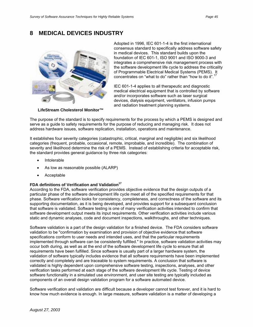
Survey of Software Assurance Techniques for Highly Reliable Systems Page 45
8 MEDICAL DEVICES INDUSTRY
Adopted in 1996, IEC 601-1-4 is the first international consensus standard to specifically address software safety in medical devices. This standard builds upon the foundation of IEC 601-1, ISO 9001 and ISO 9000-3 and integrates a comprehensive risk management process with the software development life cycle to address the criticality of Programmable Electrical Medical Systems (PEMS). It concentrates on “what to do” rather than “how to do it”.17 IEC 601-1-4 applies to all therapeutic and diagnostic medical electrical equipment that is controlled by software and/or incorporates software such as laser surgical devices, dialysis equipment, ventilators, infusion pumps and radiation treatment planning systems.
LifeStream Cholesterol Monitor™ The purpose of the standard is to specify requirements for the process by which a PEMS is designed and serve as a guide to safety requirements for the purpose of reducing and managing risk. It does not address hardware issues, software replication, installation, operations and maintenance. It establishes four severity categories (catastrophic, critical, marginal and negligible) and six likelihood categories (frequent, probable, occasional, remote, improbable, and incredible). The combination of severity and likelihood determine the risk of a PEMS. Instead of establishing criteria for acceptable risk, the standard provides general guidance by three risk categories:
• Intolerable
• As low as reasonable possible (ALARP)
• Acceptable FDA definitions of Verification and Validation17 According to the FDA, software verification provides objective evidence that the design outputs of a particular phase of the software development life cycle meet all of the specified requirements for that phase. Software verification looks for consistency, completeness, and correctness of the software and its supporting documentation, as it is being developed, and provides support for a subsequent conclusion that software is validated. Software testing is one of many verification activities intended to confirm that software development output meets its input requirements. Other verification activities include various static and dynamic analyses, code and document inspections, walkthroughs, and other techniques. Software validation is a part of the design validation for a finished device. The FDA considers software validation to be "confirmation by examination and provision of objective evidence that software specifications conform to user needs and intended uses, and that the particular requirements implemented through software can be consistently fulfilled." In practice, software validation activities may occur both during, as well as at the end of the software development life cycle to ensure that all requirements have been fulfilled. Since software is usually part of a larger hardware system, the validation of software typically includes evidence that all software requirements have been implemented correctly and completely and are traceable to system requirements. A conclusion that software is validated is highly dependent upon comprehensive software testing, inspections, analyses, and other verification tasks performed at each stage of the software development life cycle. Testing of device software functionality in a simulated use environment, and user site testing are typically included as components of an overall design validation program for a software automated device. Software verification and validation are difficult because a developer cannot test forever, and it is hard to know how much evidence is enough. In large measure, software validation is a matter of developing a
August 27, 2003

Survey of Software Assurance Techniques for Highly Reliable Systems Page 46
"level of confidence" that the device meets all requirements and user expectations for the software automated functions and features of the device. Measures such as defects found in specifications documents, estimates of defects remaining, testing coverage, and other techniques are all used to develop an acceptable level of confidence before shipping the product. The level of confidence, and therefore the level of software validation, verification, and testing effort needed, will vary depending upon the safety risk (hazard) posed by the automated functions of the device. Reliability Achieved Strengths:
• Scales well
• Not overly prescriptive when levying requirements. Relies upon implementation by qualified and competent people
• Builds upon ISO 9000 and many companies are moving toward or already have ISO certification
• Comprehensive risk management process that is integral with software life cycle
• Adopted by the FDA
Areas for Improvement:
• Expand scope to include software that is used to control the manufacture of pharmaceuticals, blood banks and other biological products
• Analysis of recalls of medical devices by Siemens AG applications indicate that 61% of problems were due to deficient software engineering and risk management processes.
August 27, 2003

Survey of Software Assurance Techniques for Highly Reliable Systems Page 47
9 TRANSPORTATION INDUSTRY14
The transportation industry includes passenger vehicles, trucks, buses, off-highway vehicles and trains. Operators of these vehicles range from teen-age drivers to railroad engineers. These vehicles must operate safely under various weather and road/track conditions. Railroads require sophisticated railway control and protection systems for scheduling trains so they do not collide. These systems rely heavily on correct data including track layout, signal locations, speed limitations and signaling control tables. The following standards contain best practices based on lessons learned in development of transportation industry software.
• EN (European Norms) 50128:1997, Railway Applications: Software for Railway Control and Protection Systems, the European committee for Electrotechnical Standardisation (CENELEC)
• Development Guidelines for Vehicle-Based Software, The Motor Industry Software Reliability Association (MISRA™), November 1994
• JA 1002 Software Reliability Program Standard, Society of Automotive Engineers (SAE), 1998 Each standard is described below including overall effectiveness and areas for improvement. EN 50128
EN 50126Railway Applications – Dependability
for Guided Transport Systems –Part 2: Safety
TC 256Mechanical Safety
EN 50155Vehicle
Electronics Safety
EN 50128Software Railway
Control and ProtectionSystems
ETSI/CMGTelecom
Dependability
EN 50129Safety-Related
Electronic Railway Control and
Protection Systems
Figure 11: Structure of CENELEC Railway Dependability Standards
August 27, 2003

Survey of Software Assurance Techniques for Highly Reliable Systems Page 48
EN50128 identifies “methods which need to be used in order to provide software which meets the demands for safety and integrity”. It is organized around the concept of Software Integrity Levels explained in Appendix A. All modules belong to the highest SIL unless partitioning can be demonstrated. Since SILs correspond to risk, EN 50126 defines a detailed risk classification scheme which utilizes a combination of qualitative and quantitative measures. EN 50126 defines six probability levels (incredible, improbable, remote, occasional, probable, frequent) and four safety hazard severity levels (catastrophic, critical, marginal, insignificant). It then correlates the hazard probability levels and safety hazard severity levels into four risk regions (intolerable, undesirable, tolerable and negligible). The standard provides a response for each region, for example: risk in the intolerable region “shall be eliminated”. EN 50128 assigns activities, techniques and measures to be performed throughout the lifecycle based on the SIL to be achieved and assessed as shown in the table below. It defines seven lifecycle phases (requirements, specification, architecture specification, design and development, software/hardware integration, validation, assessment and maintenance). Two activities are ongoing throughout the lifecycle including: verification and quality assurance. Development begins only after system-level performance, safety, reliability and security requirements have been allocated to software. Table 6: EN 50128 Assignment of Techniques and Measures By SIL and Lifecycle Phase
Techniques and Measures SIL 1-2
(Lower)
SIL 3-4
(Higher)
Lifecycle Phase
Structured methodologies (JSD, MASCOT, SADT, SDL, SSADM, Yourdon)
HR HR Requirements, Specification, Design and Development
Formal Methods (CCS, CSP, HOL, LOTOS, OBJ, Temporal Logic, VDM, Z)
R HR Requirements, Specification, Design, Development and Verification
AI, Dynamic Reconfiguration NR NR Architecture Specification
Safety Bags, Recovery Blocks, Retry Fault Recovery
R R Architecture Specification
Partitioning, Defensive Programming, Fault Detection and Diagnosis, Error Detection, Failure Assertion, Diverse Programming, SFMECA, SFTA
R HR Architecture Specification
Design and coding standards
Data Recording and Analysis
HR M Design, Development and Maintenance
Object-oriented Analysis and Design (OOAD) R R Design and Development
Modular Approach M M Design, Development
Static Analysis
Dynamic Analysis
HR HR Verification
August 27, 2003

Survey of Software Assurance Techniques for Highly Reliable Systems Page 49
Software Quality Metrics R R Verification
Functional Testing HR HR SW/HW Integration and Validation
Probabilistic Testing
Performance Testing
R HR SW/HW Integration and Validation
Modeling R R Validation
Checklists
Static Analysis
Field Trials
HR HR Assessment
Dynamic Analysis
SFMECA, SFTA
Common Cause Failure Analysis
R HR Assessment
Cause Consequence Diagrams
Event Tree Analysis
Markov Modeling
Reliability Block Diagrams
R R Assessment
Change Impact Analysis HR M Maintenance M – mandated, HR – Highly Recommended, R – Recommended, NR – not recommended, F - forbidden Reliability Achieved Strengths:
• Guidance about the techniques and measures to use to achieve specified SILs
• Informal industry consensus of best practices
• Allows developers to select the lifecycle model and development methodology appropriate for the application
• Provides common approach across the European community to achieve and assess software dependability in railway applications
• Simplifies railway regulatory tasks of both the Railway authorities and railway support industry
• Facilitates collection and analysis of consistent metrics for improvement of railway software products and processes used to develop them
Areas for Improvement:
• Requires several data items to be developed and assessed throughout the system lifecycle
• Provide more guidance on how to assemble and present adequate evidence or proof that a system is safe and reliable
MISRA™
August 27, 2003

Survey of Software Assurance Techniques for Highly Reliable Systems Page 50
The Motor Industry Software Reliability Association (MISRA™) Consortium was created in response to an initiative of the U.K. Safety Critical System Research Programme. The controlling members include Ford Motor Company, Jaguar Cars Ltd, Rolls Royce and Associates, et al. MISRA™ guidelines compare software to other automobile components and acknowledge that software is not physical, is complex and easily changed and
software errors are systematic not random. Additionally, automotive software is different than other software because it emphasizes data-driven algorithms, parameter optimization, adaptive control and on-board diagnostics. The goal of MISRA™ is to promote a unified approach across the automotive industry. Examples of automotive software applications include:
• Power train systems (engine management, transmission control, cruise control)
• Body systems (exterior lights, wiper systems, central locking, electric seat controls and windows and security systems)
• Chassis systems (anti-lock braking, active suspension)
• Other systems (air bags, sound systems, instrument pack, heating and ventilation, etc)
MISRA™ defines seven lifecycle activities (project planning, integrity, requirements specification, design, programming, testing and product support). During the integrity phase, an integrity level is assigned that corresponds to the inherent risk from using the system. These integrity levels are the same as the SILs described in Appendix A.
Automotive software failure management techniques are based on the concept of controllability. Controllability is defined as “the ability of vehicle occupants to control the situation following a failure”. There are five controllability categories (uncontrollable, difficult to control, debilitating, distracting and nuisance). The SIL is determined by correlating the controllability of a hazard with the outcome and acceptable failure rate as shown below:
Table 7: Correlation Between Controllability and SILS
Controllability Category
Definition Most Likely Outcome
Acceptable Failure Rate
SIL
Uncontrollable Human action has no effect
Extremely severe Extremely improbable
4
Difficult to Control
Potential for human action
Likely very severe Very remote 3
Debilitating Sensible human response
At worst severe Remote 2
Distracting Operational limitations, normal human response
At worst minor Unlikely 1
Nuisance Safety not an issue Customer Dissatisfaction
Reasonably possible 0
August 27, 2003

Survey of Software Assurance Techniques for Highly Reliable Systems Page 51
Software should be designed to support extensive fault management features. Safety analysis of default states should consider driving situations and how combinations of default states interact with those situations. It should also consider the effects of system reset, so as to maintain a safe state.
MISRA™ recommends robust onboard diagnostics for both the driver and the maintenance personnel. SFTA and SFEMCA should be used as the basis for developing onboard diagnostic strategy. The diagnostic software should relay information about failures such as incorrect sensor signals or actuators not performing as intended on demand, but not in a manner that would overload the driver with information thereby alarming or distracting him or her.
Automotive systems operate in demand-mode and continuous mode scenarios. For example, luxury class automobiles feature more than 50 electronic control units with microprocessors that assist and protect by intervening in operational and driving processes, but there is no central computer controlling, monitoring or coordinating these functions. Reliability Achieved Strengths:
• Represent a wealth of domain specific knowledge and insight
• Contain information and recommendations in a logical, easy to use format
• Include guidance on risk mitigation strategies
Areas for Improvement:
• Adoption is voluntary
• Used mostly in the U. K., but beginning to gain acceptance in the United States SAE JA 1002 The G-11 Reliability, Maintainability, Supportability and Logistics (RMSL) division of the Society of Automotive Engineers (SAE) was established to develop international consensus standards for reliability, maintainability, supportability and logistics in response to DoD acquisition forms. The G-11 committee was chartered to develop two task guides: one for software reliability and another for software supportability. SAE JA 1002 is the Software Reliability Program Standard developed as part of task one, the software reliability guide. JA 1002 defines requirements for and structure of an effective software reliability program. It has two key components: Software Reliability Plan and Software Reliability Case. The plan-case framework identifies tasks and activities needed to achieve and assess a given level of software reliability, then closes the loop by providing proof that such software reliability was achieved. Sample Software Reliability Plan, Software Reliability Case and Case Evidence are shown below:
August 27, 2003

Survey of Software Assurance Techniques for Highly Reliable Systems Page 52
Figure 12: Sample Outline for a Software Reliability Plan
1. MANAGING THE SOFTWARE RELIABILITY PROGRAM ACTIVITIES
1.1 Define purpose, scope of plan and program reliability goals and objectives
1.2 Nomenclature and project references
1.3 Program management functions, responsibility, authority, interaction between system and software reliability programs
1.4 Resources needed, quantity and type
1.4.1 Personnel education, experience and certification
1.4.2 Equipment
1.4.3 Schedule showing when resources are needed
1.4.4 Training Requirements
1.5 Definition and approval of lifecycle processes
1.6 Plan approval and maintenance
1.7 Acquirer interaction/involvement
1.8 Subcontractor management
2. PERFORMING SOFTWARE RELIABILITY PROGRAM ACTIVITIES
2.1 Define lifecycle model and methodology, interaction with systems engineering
2.2 Identify specific static and dynamic analyses to be performed throughout lifecycle
2.2.1 Metrics to be collected and analyzed
2.2.2 Metrics to be reported
2.3 Analysis of pre-existing software
2.4 SQM and SCM roles and responsibilities
2.5 Training end users, operations and support staff
2.6 Decommissioning
3. DOCUMENTING SOFTWARE RELIABILITY PROGRAM ACTIVITES
3.1 Lifecycle artifacts
3.2 Software Reliability Case
August 27, 2003
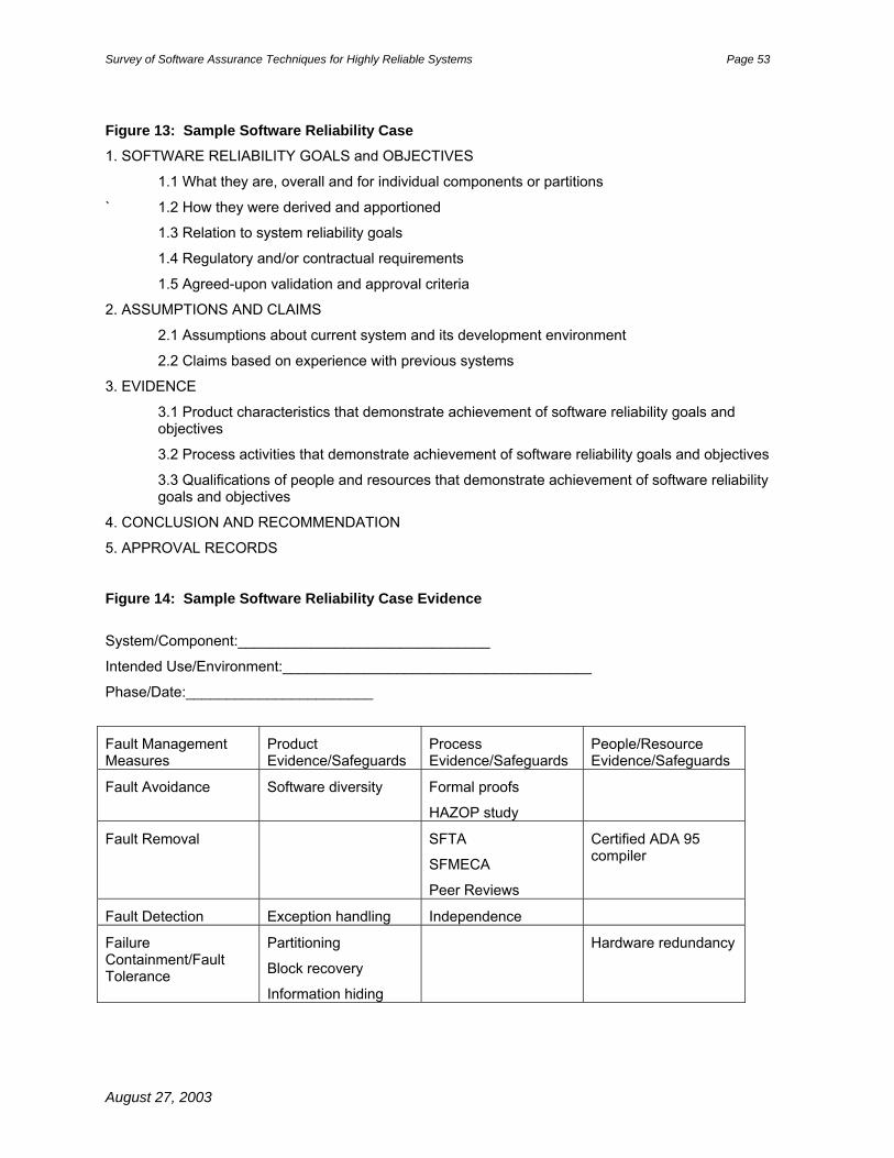
Survey of Software Assurance Techniques for Highly Reliable Systems Page 53
Figure 13: Sample Software Reliability Case
1. SOFTWARE RELIABILITY GOALS and OBJECTIVES
1.1 What they are, overall and for individual components or partitions
` 1.2 How they were derived and apportioned
1.3 Relation to system reliability goals
1.4 Regulatory and/or contractual requirements
1.5 Agreed-upon validation and approval criteria
2. ASSUMPTIONS AND CLAIMS
2.1 Assumptions about current system and its development environment
2.2 Claims based on experience with previous systems
3. EVIDENCE
3.1 Product characteristics that demonstrate achievement of software reliability goals and objectives
3.2 Process activities that demonstrate achievement of software reliability goals and objectives
3.3 Qualifications of people and resources that demonstrate achievement of software reliability goals and objectives
4. CONCLUSION AND RECOMMENDATION
5. APPROVAL RECORDS Figure 14: Sample Software Reliability Case Evidence
System/Component:_______________________________
Intended Use/Environment:______________________________________
Phase/Date:_______________________
Fault Management Measures
Product Evidence/Safeguards
Process Evidence/Safeguards
People/Resource Evidence/Safeguards
Fault Avoidance Software diversity Formal proofs
HAZOP study
Fault Removal SFTA
SFMECA
Peer Reviews
Certified ADA 95 compiler
Fault Detection Exception handling Independence
Failure Containment/Fault Tolerance
Partitioning
Block recovery
Information hiding
Hardware redundancy
August 27, 2003

Survey of Software Assurance Techniques for Highly Reliable Systems Page 54
Reliability Achieved Strengths:
• SAE JA 1002 is meant to be used within the context of an overall system reliability program as defined in SAE JA 1000, System Reliability Program Standard.
• Comprehensive, yet practical
• Progressive – promotes the definition and assessment of software reliability throughout the entire lifecycle
Areas for Improvement:
• Doesn’t scale well – must complete a plan and case for each component
• Doesn’t address issue of compliance assessment
August 27, 2003
Survey of Software Assurance Techniques for Highly Reliable Systems Page 55
10 APPENDIX A - SOFTWARE INTEGRITY LEVELS (SILs) Software Integrity Levels (SILs) describe the level of risk associated with the use of the software:
0. Non-safety related
1. Low
2. Medium
3. High
4. Very high
August 27, 2003

Survey of Software Assurance Techniques for Highly Reliable Systems Page 56
11 APPENDIX B – SAFETY CASE In order to meet some regulatory guidelines, developers must build a safety case as a means of documenting the safety justification of a system. The safety case is a record of all safety activities associated with a system throughout its life. Items contained in a safety case include the following:
• Description of the system/software
• Evidence of competence of personnel involved in development of safety critical software and any safety activity
• Specification of safety requirements
• Results of hazard and risk analysis
• Details of risk reduction techniques employed
• Results of design analysis showing that the system design meets all required safety targets
• Verification and validation strategy
• Results of all verification and validation activities
• Records of safety reviews
• Records of any incidents which occur throughout the life of the system
• Records of all changes to the system and justification of its continued safety18
August 27, 2003

Survey of Software Assurance Techniques for Highly Reliable Systems Page 57
12 DEFINITIONS and ACRONYMS The references for the definitions in this Standard are NASA documents and consensus standards.
12.1 Definitions Acquirer: The entity or individual who specifies the requirements and accepts the resulting software products. The acquirer is usually NASA or an organization within the Agency. Audit: An independent examination of a work product or set of work products to assess compliance with specifications, standards, contractual agreements, or other criteria. [IEEE 610.12] Assessment: A systematic examination to determine whether a software product meets its specified requirements.
Certification: Legal recognition by the certification authority that a software product complies with the requirements19 Formal Review: The test, inspection, or analytical processes by which a group of configuration items comprising a system are verified to have met specific contractual performance requirements. Functional Configuration Audit (FCA): An audit conducted to verify that the development of a configuration item has been completed satisfactorily, that the item has achieved the performance and functional characteristics specified in the functional or allocated configuration identification, and that its operational and support documents are complete and satisfactory. Independent Verification and Validation (IV&V): Verification and validation performed by an organization that is technically, managerially, and financially independent. IV&V, as a part of Software Assurance, plays a role in the overall NASA software risk mitigation strategy applied throughout the life cycle, to improve the safety and quality of software systems. In addition to performing a second check on the requirements traceability and general process and product reviews, IV&V is used to apply additional analyses to safety critical products. Insight: Surveillance mode requiring the monitoring of customer-identified metrics and contracted milestones. Insight is a continuum that can range from low intensity, such as reviewing quarterly reports, to high intensity, such as performing surveys and reviews.[NPG 8735.2]
Mission critical: Mission critical means the loss of capability leading to possible reduction in mission effectiveness20 Examples of mission critical software can be found in unmanned space missions like Deep Space One and others. Also called Class B software at NASA Dryden Flight Research Center (DFRC). Nonconformance: A deviation from specified standards, procedures, plans, requirements, or designs. Oversight: Surveillance mode that is in line with the supplier's processes. The customer retains and exercises the right to concur or nonconcur with the supplier's decisions. Nonconcurrence must be resolved before the supplier can proceed. Oversight is a continuum that can range from low intensity, such as customer concurrence in reviews (e.g., PDR, CDR), to high intensity oversight, in which the customer has day-today involvement in the supplier's decision-making process (e.g., software inspections). [NPG 8735.2] Peer Review: A review of a software work product, following defined procedures, by peers of the producers of the product for the purpose of identifying defects and improvements. [CMM-SW] Physical Configuration Audit (PCA): An audit conducted to verify that a configuration item, as built, conforms to the technical documentation that defines it.
August 27, 2003

Survey of Software Assurance Techniques for Highly Reliable Systems Page 58
Process: A set of interrelated activities, which transform inputs into outputs. [ISO 12207] Process Assurance: Activities to assure that all processes involved with the project comply with the contract and adhere to plans. Product Assurance: Activities to assure that all required plans are documented, and that the plans, software products, and related documentation comply with the contract and adhere to the plans. Provider: The entity or individual that designs, develops, implements, and tests the software products. The provider may be a contractor, a separate organization within NASA, or the acquirer and provider may be the same organization. Quality Record: A record that provides objective evidence of the extent of the fulfillment of the requirements for quality. Review: A process or meeting during which a software product or related documentation is presented to project personnel, customers, managers, software assurance personnel, users or user representatives or other interested parties for comment or approval. [IEEE 610.12] Reviews include, but are not limited to, requirements review, design review, code review, test readiness review. Other types may include peer review and formal review.
Safety: A property of a system/software meaning that the system/software will not endanger human life or the environment.
Safety-critical: Means failure or design error could cause a risk to human life.20 Examples of safety-critical software can be found in nuclear reactors, automobiles, chemical plants, aircraft, spacecraft, et al. Also called Class A software at NASA Dryden Flight Research Center (DFRC). Software: Computer programs, procedures, rules, and associated documentation and data pertaining to the operation of a computer system. Includes programs and operational data contained in hardware. [NASA-STD-2202-93] Software Assurance: The planned and systematic set of activities that ensure that software life cycle processes and products conform to requirements, standards, and procedures. [IEEE 610.12] For NASA this includes the disciplines of Software Quality (functions of Software Quality Engineering, Software Quality Assurance, Software Quality Control), Software Safety, Software Reliability, Software Verification and Validation, and IV&V. Program Metrics: Metrics related to the activities defined in the Software Assurance Program. Examples include number of reviews/audits planned vs. reviews/audits performed, software assurance effort planned vs. software assurance effort actual, and corrective actions opened vs. corrective actions closed. Software Life Cycle: The period of time that begins when a software product is conceived and ends when the software is no longer available for use. The software life cycle typically includes a concept phase, requirements phase, design phase, implementation phase, test phase, installation and checkout phase, operation and maintenance phase, and sometimes, retirement phase. [IEEE 610.12] Software Product Quality: A measure of software that combines the characteristics of low defect rates and high user satisfaction. Software Quality: The discipline of software quality is a planned and systematic set of activities to ensure quality is built into the software. It consists of software quality assurance, software quality control, and software quality engineering. As an attribute, software quality is (1) the degree to which a system, component, or process meets specified requirements. (2) The degree to which a system, component, or process meets customer or user needs or expectations. [IEEE 610.12]
August 27, 2003

Survey of Software Assurance Techniques for Highly Reliable Systems Page 59
Software Quality Assurance: The function of software quality that assures that the standards, processes, and procedures are appropriate for the project and are correctly implemented. Software Quality Control: The function of software quality that checks that the project follows its standards, processes, and procedures and produces the required internal and external (deliverable) products. Software Quality Engineering: The function of software quality that assures that quality is built into the software, that is, that reliability, maintainability, and other quality factors are built into the software. This function will often perform more in depth analyses, trade studies, and investigations on the requirements, design, code and verification processes. Software Quality Metrics: Metrics are quantitative values that measure the quality of software or the processes used to develop the software, or some attribute of the software related to the quality. Software Reliability: The discipline of software assurance that assures the optimization of the software through emphasis on requiring and building in software error prevention, fault detection, isolation, recovery, and/or reduced functionality states. It also includes a process for measuring and analyzing defects in the software products during development activities in order to find and address possible problem areas within the software. Software Safety: The discipline of software assurance that is a systematic approach to identifying, analyzing, tracking, mitigating and controlling software hazards and hazardous functions (data and commands) to ensure safer software operation within a system. Verification: The process of evaluating a system or component to determine whether the products of a given development phase satisfy the conditions imposed at the start of that phase [IEEE 610.12]. Validation: The process of evaluating a system or component during or at the end of the development process to determine whether it satisfies the specified requirements [IEEE 610.12].
August 27, 2003

Survey of Software Assurance Techniques for Highly Reliable Systems Page 60
12.2 Acronyms AA-SMA Associate Administrator for Safety and Mission Assurance CMM® Capability Maturity Model CMMISM Capability Maturity Model Integration COTS Commercial off-the-shelf software
FAA Federal Aviation Authority GOTS Government off-the-shelf software IV&V Independent Verification and Validation MOA Memorandum of Agreement MOTS Modified off-the-shelf software NPD NASA Policy Directive NPG NASA Policy Guidance RFP Request for Proposals SA Software Assurance
SAE Society of Automotive Engineers SMA Safety and Mission Assurance SOW Statement of Work SQA Software Quality Assurance V&V Verification and Validation
August 27, 2003

Survey of Software Assurance Techniques for Highly Reliable Systems Page 61
13 REFERENCES 1 Introduction to IEEE/EIA 12207 presentation by Jim Wells - Software Engineering Process Office (SEPO - D12), Software Process Improvement Working Group (SPIWG), October 13, 1999 2 Keene, S.J. “Modeling Software Reliability and maintainability Characteristics”, Reliability Review, Part I Vol. 17, No. 2, June 1997, as updated March 17, 1998. 3 NASA/CR-2002-211409 Verification & Validation of Neural Networks for Aerospace Systems, Dale Mackall, Stacy Nelson and Johann Schumann, July 2002 4 Dryden Flight Research Center Policy: Flight Operational Readiness Review (ORR) and Operational Readiness Review Panel (ORRP), DCP-X-020 Revision A 5 Dryden Handbook Code X - Airworthiness and Flight Safety Review, Independent Review, Mission Success Review, Technical Brief and Mini-Tech Brief Guidelines DHB-X-001 Revision D 6 NASA-STD-87xxx: Draft Standard for Software Assurance NASA Technical Standard, 2003 7 S. Nelson, C. Pecheur, NASA/CR 2002-211401 – Survey of NASA V&V Processes/Methods 8 Deep Space One Website: http://nmp.jpl.nasa.gov/ds1/ 9 Douglas E. Bernard, Edward B. Gamble, Jr., Nicolas F. Rouquette, Ben Smith, Yu-Wen Tung, Nicola Muscettola, Gregory A. Dorais, Bob Kanefsky, James Kurien, William Millar, Pandu Nayak, Kanna Rajan, Will Taylor. Remote Agent Experiment DS1 Technology Validation Report. Jet Propulsion Laboratory, California Institute of Technology and NASA Ames Research Center, Moffett Field. http://nmp-techval-reports.jpl.nasa.gov 10 P. Pandurang Nayak, Douglas E. Bernard, Gregory Dorais, Edward B. Gamble Jr., Bob Kanefsky, James Kurien, William Millar, Nicola Muscettola, Kanna Rajan, Nicolas Rouquette, Benjamin D. Smith, William Taylor, Yu-wen Tung. “Validating the DS1 Remote Agent Experiment”. Proceedings of the 5th International Symposium on Artificial Intelligence, Robotics and Automation in Space (iSAIRAS-99) http://rax.arc.nasa.gov/publications.html 11 Interview with Nicola Muscettola, NASA ARC, August 3, 2001 12 Reference not used
13 S. Nelson and C. Pecheur, NASA/CR 2002-211402 – V&V of Advanced Systems at NASA 14 Klaus Havelund, Mike Lowry, SeungJoon Park, Charles Pecheur, John Penix, Willem Visser, Jon L. White. “Formal Analysis of the Remote Agent Before and After Flight”. Proceedings of 5th NASA Langley Formal Methods Workshop, Williamsburg, Virginia, 13-15 June 2000. http://ase.arc.nasa.gov/pecheru/publi.html 15 Reference not used 17 Herrmann, D. S., Software Safety and Reliability, IEEE Computer Society Press Order Number BP00299, 1999.
August 27, 2003

Survey of Software Assurance Techniques for Highly Reliable Systems Page 62
18 http://encarta.msn.com/encnet/refpages/RefMedia.aspx?artrefid=761558960&refid=461541459&sec=-1&pn=1, Peter Arnold, Inc./Helga Lade The first of three boiling-water nuclear reactors at Germany's Gundremmingen plant began operating in 1966 but was permanently shut down after being decommissioned in 1983. Additional cooling systems were installed for the remaining two operational reactors at the plant in 1995. 19 http://www.delange.org/PV/PV.htm, GeorgeDeLange, June 14, 2002 20 “FDA definitions of Verification and Validation”, General Principles of Software Validation; Final Guidance for Industry and FDA Staff Document issued on: January 11, 2002 by:
U.S. Department Of Health and Human Services Food and Drug Administration Center for Devices and Radiological Health Center for Biologics Evaluation and Research
21 Neil Storey, Safety-Critical Computer Systems Addison-Wesley Longman, 1996 24 Stephen H. Kan, Metrics and Models in Software Quality Engineering Second Edition, Addison-Wesley, 2003. 23 Software Considerations in Airborne Systems and Equipment Certification, Document No RTCA (Requirements and Technical Concepts for Aviation) /DO-178B, December 1, 1992. (Copies of this document may be obtained from RTCA, Inc., 1140 Connecticut Avenue, Northwest, Suite 1020, Washington, DC 20036-4001 USA. Phone: (202) 833-9339 ) 24 Interview with Dale Mackall, Sr. Dryden Flight Research Center Verification and Validation engineer on January 16, 2003 25 Marvin V. Zelkowitz and Ioana Rus: The Role of Independent Verification and Validation in Maintaining a Safety Critical Evolutionary Software in a Complex Environment: The NASA Space Shuttle Program
August 27, 2003

REPORT DOCUMENTATION PAGE
8. PERFORMING ORGANIZATION REPORT NUMBER
10. SPONSORING/MONITORING AGENCY REPORT NUMBER
Form ApprovedOMB No. 0704-0188
12b. DISTRIBUTION CODE12a. DISTRIBUTION/AVAILABILITY STATEMENT
7. PERFORMING ORGANIZATION NAME(S) AND ADDRESS(ES)
4. TITLE AND SUBTITLE 5. FUNDING NUMBERS
6. AUTHOR(S)
1. AGENCY USE ONLY (Leave blank)
9. SPONSORING/MONITORING AGENCY NAME(S) AND ADDRESS(ES)
2. REPORT DATE 3. REPORT TYPE AND DATES COVERED
15. NUMBER OF PAGES
16. PRICE CODE
20. LIMITATION OF ABSTRACT19. SECURITY CLASSIFICATION OF ABSTRACT
18. SECURITY CLASSIFICATION OF THIS PAGE
17. SECURITY CLASSIFICATION OF REPORT
14. SUBJECT TERMS
13. ABSTRACT (Maximum 200 words)
Standard Form 298 (Rev. 2-89)Prescribed by ANSI Std. Z39-18298-102
NSN 7540-01-280-5500
Public reporting burden for this collection of information is estimated to average 1 hour per response, including the time for reviewing instructions, searching existing data sources,gathering and maintaining the data needed, and completing and reviewing the collection of information. Send comments regarding this burden estimate or any other aspect of thiscollection of information, including suggestions for reducing this burden, to Washington Headquarters Services, Directorate for information Operations and Reports, 1215 JeffersonDavis Highway, Suite 1204, Arlington, VA 22202-4302, and to the Office of Management and Budget, Paperwork Reduction Project (0704-0188), Washington, DC 20503.
11. SUPPLEMENTARY NOTES
Unclassified Unclassified
Unclassified — UnlimitedSubject Category 61 Distribution: StandardAvailability: NASA CASI (301) 621-0390
NASA CR-2004-212805
February 2004
Nelson ConsultingMS 269-1Ames Research CenterMoffett Field, CA 94035-1000
National Aeronautics and Space AdministrationWashington, DC 20546-0001
67
Survey of Software Assurance Techniques for Highly Reliable Systems
Stacy Nelson (Nelson Consulting)
Software Certification, Aerospace Software, Verification and Validation;SoftwareSafety, Software Development
Contractor Report
Point of Contact: Stacy Nelson Ames Research Center, MS 269-1, Moffett Field, CA 94035-1000 (650) 604-3588
QSS NAS2-00065, 3006-NEL-001
This document provides a survey of software assurance techniques for highly reliable systems including a discus-sion of relevant safety standards for various industries in the United States and Europe, as well as examples ofmethods used during software development projects. It contains one section for each industry surveyed: Aero-space, Defense, Nuclear Power, Medical Devices and Transportation. Each section provides an overview ofapplicable standards and examples of a mission or software development project, software assurance techniquesused and reliability achieved.