![Routing Protocols for Vehicular Adhoc Networks …cisjournal.org/journalofcomputing/archive/vol5no1/vol5no1_4.pdf · reactive approaches for routing [17]. Proactive approaches maintain](https://static.fdocuments.in/doc/165x107/5ac806c47f8b9a42358bf316/routing-protocols-for-vehicular-adhoc-networks-approaches-for-routing-17.jpg)
Survey of Reactive and Hybrid Routing Protocols for Mobile ... · Survey of Reactive and Hybrid...
24
193 International Journal of Communication Networks and Information Security (IJCNIS) Vol. 3, No. 3, December 2011 Survey of Reactive and Hybrid Routing Protocols for Mobile Ad Hoc Networks Haseeb Zafar 1,2 , Nancy Alhamahmy 1 , David Harle 1 and Ivan Andonovic 1 1 Department of Electronic & Electrical Engineering University of Strathclyde, Glasgow, UK 2 Department of Computer Systems Engineering University of Engineering & Technology, Peshawar, Pakistan [email protected] Abstract: Mobile Ad Hoc Networks (MANETs) are wireless communication networks that operate without the need for any infrastructure. They are characterized by challenging environments; where the nodes are in constant motion, bandwidth and other resources are limited and the transmission medium prone to errors and collisions. Since wireless transmission ranges are limited, data often has to be relayed through multiple hops, which is why routing protocols are necessary to determine the best routes to send data across. There are numerous MANET routing protocols, categorized in different ways. This paper presents an overview of MANETs routing issues as well as a detailed discussion of the operating principles behind a few selected routing protocols and their relative performance. Keywords: mobile ad hoc networks, reactive routing protocols, hybrid routing protocols, performance comparison. 1. Introduction Mobile Ad Hoc Networks (MANETs) are wireless networks formed by several nodes communicating on a peer-to-peer basis without being connected to any fixed infrastructure. These nodes could be laptop computers, personal digital assistants, mobile phones or sensors dispersed in an area to measure certain data and send the information to a larger node. Where a source node and a destination node are not within direct range, they communicate through multi-hop routing, i.e. nodes in between them relay messages between source and destination. There are numerous situations in which MANETs can be very useful, some of these are: emergency and rescue situations, military applications, conferences and sensor networks [1,2]. There are characteristics of MANETs that make their operations more complicated than ordinary infrastructure networks, these include: mobility, limited resources, high error rates due to broadcast nature of radio channel, limited bandwidth, hidden and exposed terminal problem and of particular interest here routing [1,3,12,21]. The rest of the paper is organized as follows. Section 2 presents routing in MANETs. A closer look at the selected protocols is discussed in Section 3. Comparison of the selected protocols is presented in Section 4 and concluding remarks are made in Section 5. 2. Routing in MANETs Routing protocols in MANETs are responsible for deciding on the best (multi-hop) paths to send data across from source to destination. Soon after the introduction of MANETs, it became evident that routing protocols used for wired networks are not suitable for MANET applications, because of the constraints described in Section 1. Initially, MANET- versions of popular wired network routing protocols were introduced, but these were not very efficient. Examples include Destination-Sequenced Distance Vector (DSDV) protocol and Optimized Link State (OLSR) protocol, which are optimized versions of distance vector and link state routing protocols commonly used in wired networks. Numerous MANET-specific routing protocols were later developed to provide more efficient routing. In the remainder of this section, the different ways of classifying MANET routing protocols will be discussed, as well as the main routing approaches commonly used. Because there are so many routing protocols used in MANETs, using different operating principles, there are several ways of classifying them, and each protocol does not necessarily have to belong to only one category. A detailed hierarchical categorization is presented in [4], based on the communication model (whether the protocol is multi channel or single channel), structure in terms of whether all nodes are treated uniformly, state information (i.e. whether nodes maintain information about the whole network topology, or a limited amount of information about their neighbors) and finally routing information update mechanism. This classification approach is illustrated in Figure 1. 2.1 Communication Model A routing protocol can be either designed for single channel or multi channel communications. Multi channel communications are used mainly in Time Division Multiple Access (TDMA) and Code Division Multiple Access (CDMA). Single channel communications refer to networks that use Carrier Sense Multiple Access – Collision Avoidance (CSMA/CA), such as IEEE 802.11 wireless networks. The scope of this paper is limited to single channel networks [4].
Transcript of Survey of Reactive and Hybrid Routing Protocols for Mobile ... · Survey of Reactive and Hybrid...
193
International Journal of Communication Networks and Information Security (IJCNIS) Vol. 3, No. 3, December 2011
Survey of Reactive and Hybrid Routing Protocols for Mobile Ad Hoc Networks
Haseeb Zafar1,2, Nancy Alhamahmy1, David Harle1 and Ivan Andonovic1
1Department of Electronic & Electrical Engineering
University of Strathclyde, Glasgow, UK 2Department of Computer Systems Engineering
University of Engineering & Technology, Peshawar, Pakistan [email protected]
Abstract: Mobile Ad Hoc Networks (MANETs) are wireless
communication networks that operate without the need for any infrastructure. They are characterized by challenging environments; where the nodes are in constant motion, bandwidth and other resources are limited and the transmission medium prone to errors and collisions. Since wireless transmission ranges are limited, data often has to be relayed through multiple hops, which is why routing protocols are necessary to determine the best routes to send data across. There are numerous MANET routing protocols, categorized in different ways. This paper presents an overview of MANETs routing issues as well as a detailed discussion of the operating principles behind a few selected routing protocols and their relative performance.
Keywords: mobile ad hoc networks, reactive routing protocols, hybrid routing protocols, performance comparison.
1. Introduction Mobile Ad Hoc Networks (MANETs) are wireless networks formed by several nodes communicating on a peer-to-peer basis without being connected to any fixed infrastructure. These nodes could be laptop computers, personal digital assistants, mobile phones or sensors dispersed in an area to measure certain data and send the information to a larger node. Where a source node and a destination node are not within direct range, they communicate through multi-hop routing, i.e. nodes in between them relay messages between source and destination. There are numerous situations in which MANETs can be very useful, some of these are: emergency and rescue situations, military applications, conferences and sensor networks [1,2]. There are characteristics of MANETs that make their operations more complicated than ordinary infrastructure networks, these include: mobility, limited resources, high error rates due to broadcast nature of radio channel, limited bandwidth, hidden and exposed terminal problem and of particular interest here routing [1,3,12,21].
The rest of the paper is organized as follows. Section 2 presents routing in MANETs. A closer look at the selected protocols is discussed in Section 3. Comparison of the selected protocols is presented in Section 4 and concluding remarks are made in Section 5.
2. Routing in MANETs Routing protocols in MANETs are responsible for deciding on the best (multi-hop) paths to send data across from source to destination. Soon after the introduction of MANETs, it became evident that routing protocols used for wired
networks are not suitable for MANET applications, because of the constraints described in Section 1. Initially, MANET-versions of popular wired network routing protocols were introduced, but these were not very efficient. Examples include Destination-Sequenced Distance Vector (DSDV) protocol and Optimized Link State (OLSR) protocol, which are optimized versions of distance vector and link state routing protocols commonly used in wired networks. Numerous MANET-specific routing protocols were later developed to provide more efficient routing. In the remainder of this section, the different ways of classifying MANET routing protocols will be discussed, as well as the main routing approaches commonly used.
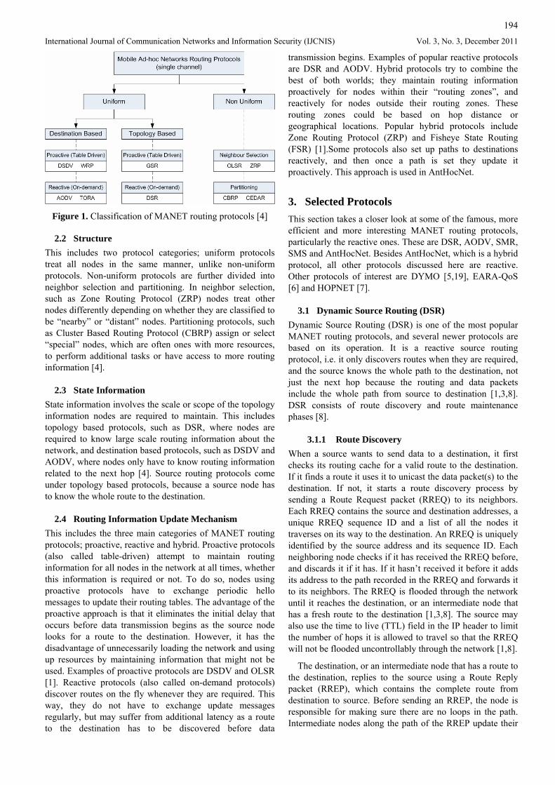
Because there are so many routing protocols used in MANETs, using different operating principles, there are several ways of classifying them, and each protocol does not necessarily have to belong to only one category. A detailed hierarchical categorization is presented in [4], based on the communication model (whether the protocol is multi channel or single channel), structure in terms of whether all nodes are treated uniformly, state information (i.e. whether nodes maintain information about the whole network topology, or a limited amount of information about their neighbors) and finally routing information update mechanism. This classification approach is illustrated in Figure 1.
2.1 Communication Model A routing protocol can be either designed for single channel or multi channel communications. Multi channel communications are used mainly in Time Division Multiple Access (TDMA) and Code Division Multiple Access (CDMA). Single channel communications refer to networks that use Carrier Sense Multiple Access – Collision Avoidance (CSMA/CA), such as IEEE 802.11 wireless networks. The scope of this paper is limited to single channel networks [4].
194
International Journal of Communication Networks and Information Security (IJCNIS) Vol. 3, No. 3, December 2011
Figure 1. Classification of MANET routing protocols [4]
2.2 Structure This includes two protocol categories; uniform protocols treat all nodes in the same manner, unlike non-uniform protocols. Non-uniform protocols are further divided into neighbor selection and partitioning. In neighbor selection, such as Zone Routing Protocol (ZRP) nodes treat other nodes differently depending on whether they are classified to be “nearby” or “distant” nodes. Partitioning protocols, such as Cluster Based Routing Protocol (CBRP) assign or select “special” nodes, which are often ones with more resources, to perform additional tasks or have access to more routing information [4].
2.3 State Information State information involves the scale or scope of the topology information nodes are required to maintain. This includes topology based protocols, such as DSR, where nodes are required to know large scale routing information about the network, and destination based protocols, such as DSDV and AODV, where nodes only have to know routing information related to the next hop [4]. Source routing protocols come under topology based protocols, because a source node has to know the whole route to the destination.
2.4 Routing Information Update Mechanism This includes the three main categories of MANET routing protocols; proactive, reactive and hybrid. Proactive protocols (also called table-driven) attempt to maintain routing information for all nodes in the network at all times, whether this information is required or not. To do so, nodes using proactive protocols have to exchange periodic hello messages to update their routing tables. The advantage of the proactive approach is that it eliminates the initial delay that occurs before data transmission begins as the source node looks for a route to the destination. However, it has the disadvantage of unnecessarily loading the network and using up resources by maintaining information that might not be used. Examples of proactive protocols are DSDV and OLSR [1]. Reactive protocols (also called on-demand protocols) discover routes on the fly whenever they are required. This way, they do not have to exchange update messages regularly, but may suffer from additional latency as a route to the destination has to be discovered before data
transmission begins. Examples of popular reactive protocols are DSR and AODV. Hybrid protocols try to combine the best of both worlds; they maintain routing information proactively for nodes within their “routing zones”, and reactively for nodes outside their routing zones. These routing zones could be based on hop distance or geographical locations. Popular hybrid protocols include Zone Routing Protocol (ZRP) and Fisheye State Routing (FSR) [1].Some protocols also set up paths to destinations reactively, and then once a path is set they update it proactively. This approach is used in AntHocNet.
3. Selected Protocols This section takes a closer look at some of the famous, more efficient and more interesting MANET routing protocols, particularly the reactive ones. These are DSR, AODV, SMR, SMS and AntHocNet. Besides AntHocNet, which is a hybrid protocol, all other protocols discussed here are reactive. Other protocols of interest are DYMO [5,19], EARA-QoS [6] and HOPNET [7].
3.1 Dynamic Source Routing (DSR) Dynamic Source Routing (DSR) is one of the most popular MANET routing protocols, and several newer protocols are based on its operation. It is a reactive source routing protocol, i.e. it only discovers routes when they are required, and the source knows the whole path to the destination, not just the next hop because the routing and data packets include the whole path from source to destination [1,3,8]. DSR consists of route discovery and route maintenance phases [8].
3.1.1 Route Discovery When a source wants to send data to a destination, it first checks its routing cache for a valid route to the destination. If it finds a route it uses it to unicast the data packet(s) to the destination. If not, it starts a route discovery process by sending a Route Request packet (RREQ) to its neighbors. Each RREQ contains the source and destination addresses, a unique RREQ sequence ID and a list of all the nodes it traverses on its way to the destination. An RREQ is uniquely identified by the source address and its sequence ID. Each neighboring node checks if it has received the RREQ before, and discards it if it has. If it hasn’t received it before it adds its address to the path recorded in the RREQ and forwards it to its neighbors. The RREQ is flooded through the network until it reaches the destination, or an intermediate node that has a fresh route to the destination [1,3,8]. The source may also use the time to live (TTL) field in the IP header to limit the number of hops it is allowed to travel so that the RREQ will not be flooded uncontrollably through the network [1,8].
The destination, or an intermediate node that has a route to the destination, replies to the source using a Route Reply packet (RREP), which contains the complete route from destination to source. Before sending an RREP, the node is responsible for making sure there are no loops in the path. Intermediate nodes along the path of the RREP update their
195
International Journal of Communication Networks and Information Security (IJCNIS) Vol. 3, No. 3, December 2011
routing caches with the routing information included in the RREP. When the source receives the RREP, it stores the route in its routing cache, and starts sending data packets.
In DSR, nodes store routing information in routing caches. A routing cache lists all routing information the node gathers about the network. This information can be gathered when the node receives or forwards routing messages (such as RREQ or RREP) received from other nodes. RFC 4728 suggests two methods of organizing the routing cache; a path cache organization or a link cache organization. In the former, routing information is listed by destination address, along with the corresponding path or paths to the destination. In link cache, the node breaks up any paths it knows of into links, and uses these links to establish a graph which reflects the topology of the network as seen by the node. To determine paths from the links stored in the routing cache, an algorithm such as Djikstra’s algorithm has to be used to determine an optimal path to the destination. Clearly, the path cache approach is simpler to implement and use, while the link cache approach is more complex, and requires more processing and resources. However, the link cache approach may be more efficient in the sense that it allows the selection of the ‘best’ paths through the network [8].
Whichever way the routing information is arranged in the cache, it is preferable to assign a timeout to each entry in the routing cache so that it expires if not used within a certain time [8]. However, DSR does not require cache entries to expire, and so they may remain in the cache for a long time [3]. Requiring cache entries to expire prevents the use of stale routes, and reduces caching capacity required. Since nodes store routing information in routing caches rather than routing tables, it is possible to store more than one route per source and destination, i.e. DSR supports multipath operation [3,8;9], in which case any method or metric can be used to choose from amongst different routes available to a destination, for instance least number of hops [8].
3.1.2 Route Maintenance Route maintenance in DSR does not involve periodic “Hello” messages, i.e. DSR is beaconless. The responsibility of making sure the link is functional lies with the sending node [8]. Which is why if a link breaks, the upstream node sends a route error packet (RERR) to the source and to any other nodes sending data on paths that include the broken link. The node generating the RERR and all nodes receiving (and overhearing) it remove the broken link from their route caches. The source can then either use an alternative route to the destination, if it has one in its routing cache, or it can discover a new one by initiating a new route discovery process [1,8].
A link is considered broken if the sending node does not receive an acknowledgement after sending a packet a certain number of times. Acknowledgement can be active, such as acknowledgement messages exchanged by the MAC protocols, or passive for example when the sending node overhears the receiving node transmitting the packet to the next hop on the path. In some cases the sending node may specifically request an acknowledgement [8].
If an intermediate node that has detected a broken link has an alternative route in its routing cache it should salvage the packet, after sending the RERR to the source. Salvaging the packet involves sending it over the alternative route to the node at the other end of the broken link, instead of just dropping it [8].
3.1.3 Additional Options / Optimizations There are several optimizations that can be used to improve the performance of DSR. There include the following:
• Allowing intermediate nodes to use routing data in data packets they forward to populate their routing caches [1].
• Promiscuous listening. This allows nodes to listen, receive and process packets that are not sent to them and extract useful information about the network, such as broken links, that do not directly affect any of their data transmissions [1;3].
• DSR allows piggybacking data and routing packets to reduce overhead [1].
• Flow state extension. This is an extension to DSR that allows most packets to be routed through intermediate nodes without being required to carry the whole route from source to destination, reducing overhead [3;8].
3.2 Ad Hoc On-Demand Distance Vector (AODV) The Ad Hoc On-Demand Distance Vector (AODV) routing protocol seems very similar to DSR in many respects, but there are some important differences in the operation of the two protocols. Both protocols are on-demand, and both use route discovery and route maintenance procedures. However, AODV is not a source routing protocol, and it uses periodic “Hello” messages to maintain routes. Furthermore, AODV uses sequence numbers to prevent loops in routes, which is not required in DSR. Moreover, AODV uses routing tables to store routing information, where only one route is allowed per destination, and entries expire if they are not used for a certain time. Finally, AODV does not support multipath operation, but it supports multicasting [1,3,10,19,20,21,22].
AODV uses routing tables to store routing information, rather than the routing caches used in DSR. AODV’s routing tables can only accommodate one entry per destination. Since AODV is not a source routing protocol, the routing table lists the destinations the node is aware of and the next hop IP address to each, not the complete path. Each entry also has a timeout assigned to it, its latest known sequence number, and a set of precursors (also called predecessors), which are nodes that may be using that link, i.e. nodes that receive or sent control packets concerning the destination. In case of an error on the link, the node will forward the RERR message to all relevant precursors as well, so that they may remove the broken link from their routing tables [3,11]. Finally, a routing table entry also indicates the number of hops to the destination, i.e. hop count.
196
International Journal of Communication Networks and Information Security (IJCNIS) Vol. 3, No. 3, December 2011
AODV uses sequence numbers to prevent the use of outdated routing information. Each node must have a monotonically increasing sequence number, which it is responsible for incrementing as required. A node has to increase its own sequence number before it initiates a route discovery process, and before it replies to a route request [11]. As mentioned earlier, for each destination node in the routing table, the last known sequence number is stored. Whenever a node receives routing messages (called control packets) relating to a destination node, it decides whether to use the information in the control packet or discard it by comparing the destination sequence number in the control packet to the last known sequence number stored in its routing table. It updates its routing table with the information contained in the control packet if the sequence number in the control packet is higher than that stored in the routing table, or if the sequence numbers are equal, but the hop count to the destination in the control packet is smaller than the hop count in the routing table minus one, or if the sequence number is not known [11].
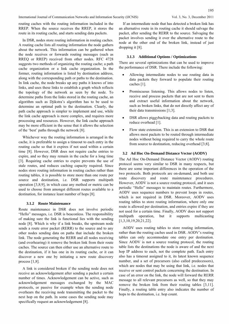
3.2.1 Route Discovery Route discovery in AODV is quite similar to than in DSR. A source node generates a RREQ packet when it needs to send information to a destination it has no route for. The format of an AODV RREQ is shown in Figure 2.
It identifies the Type of the control packet, which is always 1 for RREQ messages. The letters J, R, G, D, U are flags. J and R are used for multicast messages. G indicates whether a gratuitous RREP should be sent to the destination, this is set when it is important for the destination to be aware of a route to the source, even if an intermediate node replies to the RREQ. If it is set, the intermediate node would send two RREPs, one to the source and one to the destination. Flag D is set when the source requires that only the destination node replies with an RREP, not an intermediate node, and flag U is used when the sequence number is unknown. The ‘Reserved’ field is set to zero, and the hop count is initially set to zero at the source node, and incremented at each hop.
Rather than flooding the RREQ message, an expanding ring search is usually preferred. In an expanding ring search the source attempts to search for the destination within a limited area within its neighborhood, which is incrementally increased if the destination is not found. This prevents uncontrolled flooding of RREQ messages throughout the network. The “search area” and “neighborhood” are defined in terms of the hop count from the source, and the expanding ring search is implemented using the TTL field in the IP header of the RREQ packet [11].
When a source node generates an RREQ, it is required to wait for a certain time (determined depending on the network) before generating another RREQ for the same destination. After a number of retries (also determined depending on the network) it can declare the destination unreachable, drop packets waiting to be sent and notify the application [11].
A node receiving an RREQ discards it if it has received an RREQ with the same ID from the same source recently (“recently” would depend on the definition of “path discovery time” specified for the network). Otherwise it processes the RREQ. Processing the RREQ by the node involves incrementing the hop count in the RREQ by one, searching for a route to the RREQ source in the routing table. If an entry is found it is updated with the source’s sequence number, next hop to the source (which is the source IP address in the IP header) and hop count to the source. Also, the lifetime field of the entry (its expiry timeout) is refreshed. If no entry is found a new one is created to include the same information. Now that the node has a reverse path to the source, it proceeds to determine whether it will send an RREP or forward the RREQ. A node can reply with an RREP if it is the destination, or if its routing table contains a route to the destination. Otherwise, it checks that the TTL field in the IP header is greater than 1. If it is, it decrements the TTL field by one, updates the destination sequence number in the RREQ if the destination sequence number in its routing table is larger, and having already incremented the hop count in the RREQ, it broadcasts it to all nodes in range using the IP address 255.255.255.255.
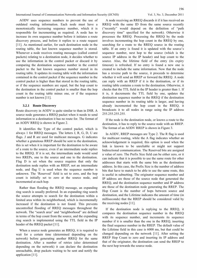
If the node is the destination node, or knows a route to the destination, it has to reply to the source node with an RREP. The format of an AODV RREP is shown in Figure 3.
In AODV, RREP messages are Type 2. The R flag is used for multicast routing, while the A flag indicates whether an acknowledgement is required, this option is used when the link is known to be unreliable or might not support bidirectional communication. The Reserved bits are assigned a value of zero. The Prefix Size field can be either zero, or it can indicate that it is possible to use the same route for other addresses that starts with the same bits as the destination address. In this case, the Prefix Size is the number of address bits that have to match to be able to use the same route, this is useful in subnetting. The originator sequence number and IP address are those of the source node that generated the RREQ, and the destination sequence number and IP address are those of the destination node generating the RREP. The Hop Count is the number of hops between source and destination, and the Lifetime indicates the amount of time (in milliseconds) that the RREP should be considered valid by the receiving nodes [11].
If the destination node is replying to the RREQ, it compares the destination sequence number in the RREQ with its sequence number, and increments its sequence number if it is smaller than the one in the RREQ, inserting the final sequence number in the RREP. The default value of the Lifetime field in this case is 6000 ms, but that could be changed depending on the network [11]. After setting the RREP Hop Count to zero and inserting its IP address and that of the originator, the destination can send the RREP to the next hop towards the source node.
197
International Journal of Communication Networks and Information Security (IJCNIS) Vol. 3, No. 3, December 2011
Figure 2. AODV RREQ message format. The top row shows the number of bits for each field [11].
Figure 3. Format of AODV RREP packet [11]
If an intermediate node is replying to the RREQ, then the Hop Count field in the RREP is the number of hops from itself to the destination, and the Destination Sequence Number field is the most recent sequence number it knows for the destination. The Lifetime in this case is remaining time for which its routing table entry for the destination will be valid. The RREP is ready to be sent once the originator and source IP addresses are entered. In addition to sending the RREP, the intermediate node will have to update the precursors in its routing table by adding the next hop to the destination in the set of precursors corresponding to the destination’s entry, and the next hop to the source in the set of precursors corresponding to the source’s entry. Finally, if the ‘G’ flag in the RREQ is set, the intermediate node would also have to send an unsolicited Gratuitous Reply. This has the same format and carries the same information as an ordinary RREP message, but the Hop Count is the number of hops from the intermediate node to the source, the Destination IP address and Sequence Number refer to the source node (the node that generated the RREQ) and the Originator IP address refers to the destination to which the Gratuitous RREP is addressed [11].
Each intermediate node along the path to the originator increments the hop count by one and forwards the RREP to the next hop. It also updates its routing table by adding a forward path entry, which includes the IP address of the destination and the previous hop (the node from which it received the RREP), the hop count to the destination and the lifetime of the entry, which is equal to the Lifetime field of the RREP. If an intermediate node receives more than one RREP for the same source and destination, it forwards the first RREP it receives, and only forwards any other RREPs if the destination sequence number is greater than the one stored in its routing table, or the hop count is less. Once the RREP reaches the source, it can start sending data. If more RREPs reach the source later, it can select the best route and
use that for the data transmission. However, each entry in the routing table can only have one route associated with it [12].
3.2.2 Route Maintenance In AODV, if any link along the established route breaks the upstream node has to send a RERR to the source node. The RERR message contains the IP address of the link on the other side of the broken link. An advantage of AODV is that the upstream node (the node that failed to send data over a link towards the destination) also forwards the RERR to any other nodes it thinks are using the broken link (i.e. the link’s precursors). These nodes in turn update their routing tables, setting the hop count to the destination to infinity and forward the RERR to any other nodes using the broken link, if there are any. This way, concerned nodes know very quickly when a link breaks. However, an entry for a broken link is not immediately removed from routing tables, as it often contains useful information. After receiving the RERR, the source can send a new RREQ to find a new route if it still has data to send [12].
The other situation where a node generates a RERR is when it receives a data packet destined for a node it does not have a routing table entry for. In this case, the RERR contains the IP address of the destination, and it is sent to the previous hop, i.e. the node that the data packet was received from [12].
AODV nodes send periodic “Hello” messages to their neighbors (TTL field is set to 1). These are used to confirm that neighbors a node is aware of are still within range, and to know if any new nodes have moved to the vicinity recently. Not all nearby nodes have to send “Hello” messages; these messages are not required if the node has sent any data packets within the past “Hello Interval”, which is by default 1 second. A Hello message is a special RREP message, unprompted by an RREQ that contains the sending node’s IP address and sequence number [12].
198
International Journal of Communication Networks and Information Security (IJCNIS) Vol. 3, No. 3, December 2011
3.2.3 Rebooting nodes When a node reboots, it loses information about its own sequence number and that of some of its routing table entry. To avoid that, a “delete period” is specified for the network during which a node that was rebooted has to ignore any control packets it receives, and send out RERR messages whenever it receives data packets. Using the “delete period” approach also ensures that no routing loops would result if the node was part of an active path before rebooting [12].
3.3 Split Multipath Routing (SMR) Split multipath routing, SMR, [13] attempts to improve performance of on-demand routing protocols by allowing the destination (receiving node) to select multiple paths to the source that are as disjoint as possible, to avoid overloading some (popular) nodes, and to make the paths as robust as possible by avoiding the weakness introduced by using different paths that use common nodes or links. SMR can be seen as a development on DSR, in that it is a source routing on-demand protocol, even though it does not use DSR’s aggressive caching approach. Its operation is divided into route discovery and route maintenance phases.
3.3.1 Route Discovery Just like in DSR and AODV, the route discovery process is initiated by a source node when it wants to send data to a destination for which it has no route. The source floods a RREQ packet, which traverses the network until it reaches the destination. Unlike DSR and AODV, however, an intermediate node cannot reply to RREQs, even if it knows a path to the destination. It is important that only the destination node replies to the RREQ since it is required to select maximally disjoint paths, and so it has to know the complete available routes to the source.
On determining that an RREQ it received is a duplicate, an intermediate node does not immediately discard it, instead it checks the previous node from which the RREQ was received and the hop count to the source. The duplicate RREQ is forwarded if it arrived on a different link, travelling through an equal or smaller number of hops than the previous RREQ. If the second RREQ arrived from the same previous hop, or travelled through more hops it is discarded. This approach helps find more maximally disjoint paths, although it means that more RREQs travel through the network. Thus, since it cannot generate RREP messages, the role of an intermediate node is now limited to determining whether a RREQ is a duplicate or not, and forwarding it where appropriate.
Once a destination receives an RREQ it quickly replies with an RREP, so that the path can be established and data transmission can begin. In the meantime, the destination also receives other RREQs from other routes. The destination waits for a certain amount of time, then selects from among the alternative routes it knows of. In [13], the algorithm is limited to selecting two maximally disjoint paths, such that the first corresponds to the first RREQ received by the destination, and the second is as disjoint as possible
compared to the first path. However, the number of paths can be increased as required.
The destination “selects” a second path by sending the source another RREP containing the addresses of all intermediate nodes along the second path. On receiving the second RREP, the source adds the new route to its routing table. It can now split the load over the two paths. Although more complex load balancing schemes can be used, in [13] a simple per packet allocation approach is used. This is a simple approach that avoids the need for complex processing, and does not require additional information about the state of the network (for instance available bandwidth) but has the disadvantage of the packets arriving out of order at the destination, requiring resequencing.
3.3.2 Route Maintenance SMR does not require periodic Hello messages to maintain active paths. Like DSR, route maintenance here is limited to dealing with a broken link along a route. When a node is unable to send a packet across a link, it generates a RERR message and sends it to the source node. The RRER includes the addresses of all nodes along the path from the node discovering the broken link to the source node, as well as the addresses of the two nodes on either side of the broken link. On receiving a RERR message, the source node deletes all occurrences of the broken link from its routing table, even if they are being used to send data to another destination.
At this point there are two approaches: the source can either immediately search for another route, while it uses the remaining route to transmit data, or it can continue sending data along the remaining path to the destination without initiating a route discovery process until that second route breaks as well. The first approach, referred to as SMS-1, results in more route discoveries being initiated, and more overhead, but ensures that data transmission is less likely to be interrupted if the second route breaks. The second approach, SMS-2, is less resilient, but reduces the load on the network resulting from control packets.
3.4 Shortest Multipath Source (SMS) routing The Shortest Multipath Source (SMS) routing protocol is another reactive source routing scheme that is designed to build on the strengths of DSR and SMR, while reducing the restrictions on the route selection scheme used in SMR to increase the number of multipaths possible. Rather than selecting routes that are node disjoint throughout as in SMR, SMS increases the number of routes possible between a source and destination by requiring that the alternative routes be partially disjoint only, i.e. that they “bypass at least one intermediate node on the primary path” [14]. The primary path here is simply the first path to be established, i.e. the path for which the source receives the first route reply message. Increasing the number of paths possible between a source and a destination makes the protocol more resistant to faults, and helps speed up recovery when a link along the path breaks. In [14], a mathematical analysis is used to prove that using a larger number of partially disjoint paths increases the network’s tolerance to faults, compared to link
199
International Journal of Communication Networks and Information Security (IJCNIS) Vol. 3, No. 3, December 2011
or node disjoint multiple paths. The operation of SMS is also divided into route discovery and route maintenance phases.
3.4.1 Route Discovery When a source node wants to send data to a destination node it first checks its cache for a route. If it finds a route it can start sending data directly. Otherwise it will have to initiate a route discovery process by sending out several route request messages (RREQ) to its neighbors [14].
In SMS not all duplicate RREQs are discarded, instead an intermediate node only forwards an RREQ if the number of hops the RREQ has traversed from the source to itself is less than or equal to the number of hops traversed by the first RREQ it received. On deciding whether to forward a duplicate RREQ, SMS nodes do not consider the incoming link on which the RREQ was received (as in SMR), since the protocol aims to build partially disjoint paths. Instead, it compares the number of hops from the source to itself in the route of the previous RREQ to the number of hops of the new RREQ, and only forwards the RREQ if the latter is less than or equal to the former [14].
In SMS, as in SMR, only the destination is allowed to reply to a RREQ. Again, this limits the role of intermediate nodes to determining whether to forward a RREQ or not, and actually forwarding the control messages. However, in SMS it is the source node that selects the paths, not the destination node. The destination node simply replies to the first few RREQs it receives. In [15], this threshold value is five, although a different threshold could be set, as mentioned in the paper. The RREP contains the path the RREQ has traversed to reach the destination, including the destination address. The destination node also saves the route path for each RREP it sends in its cache, and finally unicasts the RREP to source. When the source receives the RREP, it adds the new route to its cache and can now start sending data [14].
When the source receives more than one RREP, it is responsible for selecting paths that are partially disjoint, i.e. that are at least different in one link. It records these routes in its routing cache, after which it can start sending data. Once the source node has two or more paths to a destination, it can divide the traffic load amongst the two. In [14] a simple per-packet allocation scheme is used.
3.4.2 Route Maintenance SMS is beaconless, like DSR and SMR. When an intermediate node along a route is unable to send data to the node on the other end of the link, it declares the link broken and generates a RERR message destined to the source node. The intermediate node does not attempt to use an alternative to the broken link. When the source receives the RERR message, it removes the broken link from its routing cache, even if it is used to route data to another destination. It then randomly selects another route from the remaining alternative routes and uses it to send data.
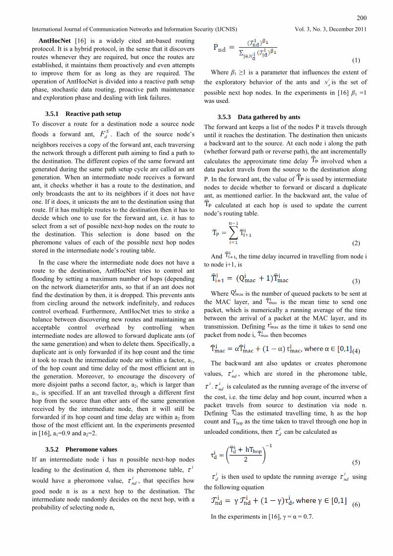
3.5 Ant based routing protocols This category of MANET routing approaches includes a wide variety of protocols that are inspired by swarm intelligence, i.e. the way ants co-operate to find the shortest path to a destination, even when faced with an obstacle. Ants communicate with each other indirectly by modifying their surroundings, this is called stigmergy. Specifically, they modify their environment by dropping off substances called pheromones as they travel through a path. This way, other ants can follow them. When ants have to crawl around some obstacle to get to their destination, which could be their nest or food source, they initially choose a random path, leaving pheromone trails. The ants that reach the destination first travel back in the reverse direction, leaving off more pheromones, encouraging other ants to use that path. This way, the shorter path soon has a higher pheromone concentration, so that ants arriving later can tell which route to take [2]. This process is illustrated in Figure 4.
Figure 4. Stigmergy in ants. In (a), ants take a straight path
between the food site and their nest. In (b), an obstacle blocks the way. Initially ants choose their path around the obstacle randomly. In (c) ants are more likely to select the
shorter path because of pheromones deposited by other ants that reached the destination quicker. As more ants travel
through a path, they deposit more pheromones, indicating the shorter path to other ants [6].
Despite some differences between the different protocols, the basic approach behind ant-based routing protocols is the use of small control packets, referred to as ants, to discover new routes and gather information about the network, then return to the node that generated them. These ants are referred to as forward ants as they travel on the forward path to discover the network, and backward ants as they travel along the reverse path with the information they gathered. This information is used to populate routing tables or other data structures where information is stored and later on used to determine the best paths through the network [16].
Ant based protocols also define ways of calculating artificial pheromone concentration along a path as a measure of how good it is. Pheromone concentrations, along with other factors such as congestion or distance, determine which path is selected from amongst several available alternatives. In ant based protocols, it is important to define the data structures (i.e. the metrics used, routing tables etc) as well as the operation of the protocol. In what follows, the principles behind AntHocNet will be presented.
200
International Journal of Communication Networks and Information Security (IJCNIS) Vol. 3, No. 3, December 2011
AntHocNet [16] is a widely cited ant-based routing protocol. It is a hybrid protocol, in the sense that it discovers routes whenever they are required, but once the routes are established, it maintains them proactively and even attempts to improve them for as long as they are required. The operation of AntHocNet is divided into a reactive path setup phase, stochastic data routing, proactive path maintenance and exploration phase and dealing with link failures.
3.5.1 Reactive path setup To discover a route for a destination node a source node floods a forward ant, . Each of the source node’s neighbors receives a copy of the forward ant, each traversing the network through a different path aiming to find a path to the destination. The different copies of the same forward ant generated during the same path setup cycle are called an ant generation. When an intermediate node receives a forward ant, it checks whether it has a route to the destination, and only broadcasts the ant to its neighbors if it does not have one. If it does, it unicasts the ant to the destination using that route. If it has multiple routes to the destination then it has to decide which one to use for the forward ant, i.e. it has to select from a set of possible next-hop nodes on the route to the destination. This selection is done based on the pheromone values of each of the possible next hop nodes stored in the intermediate node’s routing table.
SdF
In the case where the intermediate node does not have a route to the destination, AntHocNet tries to control ant flooding by setting a maximum number of hops (depending on the network diameter)for ants, so that if an ant does not find the destination by then, it is dropped. This prevents ants from circling around the network indefinitely, and reduces control overhead. Furthermore, AntHocNet tries to strike a balance between discovering new routes and maintaining an acceptable control overhead by controlling when intermediate nodes are allowed to forward duplicate ants (of the same generation) and when to delete them. Specifically, a duplicate ant is only forwarded if its hop count and the time it took to reach the intermediate node are within a factor, a1, of the hop count and time delay of the most efficient ant in the generation. Moreover, to encourage the discovery of more disjoint paths a second factor, a2, which is larger than a1, is specified. If an ant travelled through a different first hop from the source than other ants of the same generation received by the intermediate node, then it will still be forwarded if its hop count and time delay are within a2 from those of the most efficient ant. In the experiments presented in [16], a1=0.9 and a2=2.
3.5.2 Pheromone values If an intermediate node i has n possible next-hop nodes leading to the destination d, then its pheromone table, would have a pheromone value, , that specifies how good node n is as a next hop to the destination. The intermediate node randomly decides on the next hop, with a probability of selecting node n,
iτindτ
(1)
Where β1 ≥1 is a parameter that influences the extent of the exploratory behavior of the ants and is the set of possible next hop nodes. In the experiments in [16] β
i
dN
1 =1 was used.
3.5.3 Data gathered by ants The forward ant keeps a list of the nodes P it travels through until it reaches the destination. The destination then unicasts a backward ant to the source. At each node i along the path (whether forward path or reverse path), the ant incrementally calculates the approximate time delay involved when a data packet travels from the source to the destination along P. In the forward ant, the value of is used by intermediate nodes to decide whether to forward or discard a duplicate ant, as mentioned earlier. In the backward ant, the value of
calculated at each hop is used to update the current node’s routing table.
(2)
And , the time delay incurred in travelling from node i to node i+1, is
(3)
Where is the number of queued packets to be sent at the MAC layer, and is the mean time to send one packet, which is numerically a running average of the time between the arrival of a packet at the MAC layer, and its transmission. Defining as the time it takes to send one packet from node i, then becomes
(4)
The backward ant also updates or creates pheromone values, , which are stored in the pheromone table,
. is calculated as the running average of the inverse of the cost, i.e. the time delay and hop count, incurred when a packet travels from source to destination via node n. Defining
indτ
iτ indτ
as the estimated travelling time, h as the hop count and Thop as the time taken to travel through one hop in unloaded conditions, then can be calculated as i
dτ
(5)
idτ is then used to update the running average using
the following equation
indτ
(6)
In the experiments in [16], γ = α = 0.7.
201
International Journal of Communication Networks and Information Security (IJCNIS) Vol. 3, No. 3, December 2011
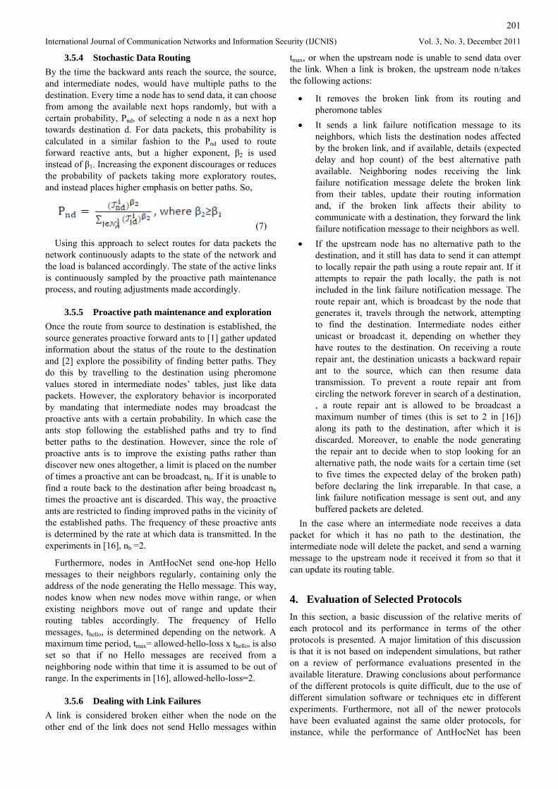
3.5.4 Stochastic Data Routing By the time the backward ants reach the source, the source, and intermediate nodes, would have multiple paths to the destination. Every time a node has to send data, it can choose from among the available next hops randomly, but with a certain probability, Pnd, of selecting a node n as a next hop towards destination d. For data packets, this probability is calculated in a similar fashion to the Pnd used to route forward reactive ants, but a higher exponent, β2 is used instead of β1. Increasing the exponent discourages or reduces the probability of packets taking more exploratory routes, and instead places higher emphasis on better paths. So,
(7)
Using this approach to select routes for data packets the network continuously adapts to the state of the network and the load is balanced accordingly. The state of the active links is continuously sampled by the proactive path maintenance process, and routing adjustments made accordingly.
3.5.5 Proactive path maintenance and exploration Once the route from source to destination is established, the source generates proactive forward ants to [1] gather updated information about the status of the route to the destination and [2] explore the possibility of finding better paths. They do this by travelling to the destination using pheromone values stored in intermediate nodes’ tables, just like data packets. However, the exploratory behavior is incorporated by mandating that intermediate nodes may broadcast the proactive ants with a certain probability. In which case the ants stop following the established paths and try to find better paths to the destination. However, since the role of proactive ants is to improve the existing paths rather than discover new ones altogether, a limit is placed on the number of times a proactive ant can be broadcast, nb. If it is unable to find a route back to the destination after being broadcast nb times the proactive ant is discarded. This way, the proactive ants are restricted to finding improved paths in the vicinity of the established paths. The frequency of these proactive ants is determined by the rate at which data is transmitted. In the experiments in [16], nb =2.
Furthermore, nodes in AntHocNet send one-hop Hello messages to their neighbors regularly, containing only the address of the node generating the Hello message. This way, nodes know when new nodes move within range, or when existing neighbors move out of range and update their routing tables accordingly. The frequency of Hello messages, thello, is determined depending on the network. A maximum time period, tmax= allowed-hello-loss x thello, is also set so that if no Hello messages are received from a neighboring node within that time it is assumed to be out of range. In the experiments in [16], allowed-hello-loss=2.
3.5.6 Dealing with Link Failures A link is considered broken either when the node on the other end of the link does not send Hello messages within
tmax, or when the upstream node is unable to send data over the link. When a link is broken, the upstream node n/takes the following actions:
• It removes the broken link from its routing and pheromone tables
• It sends a link failure notification message to its neighbors, which lists the destination nodes affected by the broken link, and if available, details (expected delay and hop count) of the best alternative path available. Neighboring nodes receiving the link failure notification message delete the broken link from their tables, update their routing information and, if the broken link affects their ability to communicate with a destination, they forward the link failure notification message to their neighbors as well.
• If the upstream node has no alternative path to the destination, and it still has data to send it can attempt to locally repair the path using a route repair ant. If it attempts to repair the path locally, the path is not included in the link failure notification message. The route repair ant, which is broadcast by the node that generates it, travels through the network, attempting to find the destination. Intermediate nodes either unicast or broadcast it, depending on whether they have routes to the destination. On receiving a route repair ant, the destination unicasts a backward repair ant to the source, which can then resume data transmission. To prevent a route repair ant from circling the network forever in search of a destination, , a route repair ant is allowed to be broadcast a maximum number of times (this is set to 2 in [16]) along its path to the destination, after which it is discarded. Moreover, to enable the node generating the repair ant to decide when to stop looking for an alternative path, the node waits for a certain time (set to five times the expected delay of the broken path) before declaring the link irreparable. In that case, a link failure notification message is sent out, and any buffered packets are deleted.
In the case where an intermediate node receives a data packet for which it has no path to the destination, the intermediate node will delete the packet, and send a warning message to the upstream node it received it from so that it can update its routing table.
4. Evaluation of Selected Protocols In this section, a basic discussion of the relative merits of each protocol and its performance in terms of the other protocols is presented. A major limitation of this discussion is that it is not based on independent simulations, but rather on a review of performance evaluations presented in the available literature. Drawing conclusions about performance of the different protocols is quite difficult, due to the use of different simulation software or techniques etc in different experiments. Furthermore, not all of the newer protocols have been evaluated against the same older protocols, for instance, while the performance of AntHocNet has been
Different metrics are used to compare protocol performance, the most common ones are:
compared to that of AODV, both SMR and SMS have been compared to DSR. Such factors, and their potential effects, will be pointed out.
International Journal of Communication Netw
• Packet delivery ratio (also referred to as Goodput): ratio of data packets delivered to their destination, to the data packets generated by the sources.
• Routing overhead: The number of routing (control) packets sent during the simulation. This is used in [17]. An alternative measure of protocol efficiency is normalized routing load, which is the number of routing packets sent divided by the total number of data packets received during the simulation. This is used in [10,13,14,16]. When routing overhead is measured in packets (not bytes), then the additional routing load caused by source routing (i.e. control and data packets are larger because they include the addresses of every node along the path to the destination) is not directly considered, in which case source routing protocols may not appear to load the network as much as they actually do, and a feature of non-source routing protocols is unaccounted for. However, the counter argument to that is that the effect of bigger packets may not have a very significant effect on overall performance, since nodes mainly compete for the wireless medium in MANETs, once a node has access to it and no collisions occur, the actual cost of sending a few extra address bytes is not that significant.
• Packet Loss: Packets that are transmitted by the source, but do not reach the destination, measured in /percent and used in [14] only.
• Average end-to-end delay: This is the sum of all delay experienced by a packet from the time it is generated by the source, till it is received by the destination. It includes delay experienced at the send buffer while the packet waits for a route to be established, delays experienced as the packet is queued at the interface queue, delays at the MAC layer caused by retransmission due to errors and propagation delay [10, 14].
• Path Optimality: This compares the distance a packet travelled from source to destination in hops, to the shortest route available at the time. This metric is used in [17] only.
• Delay Jitter: Usually used in Quality of Service (QoS) applications and can be used to quantify a protocol’s response to changes in network topology in terms of stability. It is measured by taking the average of the time gap between the arrival of three packets; for three packets arriving at times t1, t2 and t3, the delay jitter is the arithmetic average of (t3-t2)-(t2-t1) calculated for each three consecutive packets received in a session. This metric is only considered in AntHocNet experiments [16].
202
orks and Information Security (IJCNIS) Vol. 3, No. 3, December 2011
This section is based on the experiments carried out in [17] using Network Simulator-2, in which the performance of TORA, DSDV, DSR and AODV are evaluated in terms of packet delivery ratio, routing overhead and path optimality. The experiments are carried out with 50 nodes moving at an average speed of 10m/s (maximum speed 20m/s) and the results discussed when there are 10 sources, 20 sources and 30 sources. Next the experiments are repeated with 20 sources and a maximum speed of 1m/s. Details of the experiment set up are provided in [17]. Table 3 tabulates the results of the experiments, along with possible justifications and comments on factors that might affect the performance of the protocols. Since TORA and DSDV were not discussed in detail in this paper, they will be excluded from this discussion.
In experiments used to evaluate the performance of routing protocols, different scenarios are used to test the protocol’s performance in terms of some performance metrics. The aim is to determine whether the strengths of the protocol’s design will enable it to perform better in different situations, for instance, whether DSR’s aggressive caching strategy is advantageous in realistic situations, when is the additional overhead required for “Hello” messages justified etc. In this report, the results of experiments carried out in [10;13;14;16;17] are presented and discussed. Only minimum details of how the simulations were carried out are considered, and instead, the focus of this report is how each protocol performs when compared to other protocols.
Justifying protocol performance in terms of specific performance metrics above becomes easier if these metrics are related to certain characteristics of the protocols in question. Table 1 and Table 2 list the specific characteristics (positive and negative) that would affect each protocol’s performance in terms of each of the above metrics. In some cases, features of a protocol that usually result in favorable results may end up hindering its performance, for instance, DSR’s aggressive routing approach often enables it to know more about the network, thus saving some route requests and quickly shifting packets to be transmitted to an alternative route when the original one breaks etc. However, if the routing cache data is stale, (which is likely since DSR does not use lifetimes or sequence numbers to identify and remove outdated information) a source node may try to send data to a destination over a route that is no longer valid. After several failed attempts, the source would declare the link or route invalid, and will either send data over an alternative path or initiate a route request. In a situation like this DSR’s aggressive routing strategy and its inability to distinguish outdated routing data, would result in unnecessary delays and possibly packet loss, instead of speeding up the process. The same applies for periodic “Hello” messages used in AODV and AntHocNet; they help ensure routing data is up to date, but at the same time they increase overhead. Where the same characteristic can have positive and negative effect, both are shown on the same row in the respective tables.
4.1 DSR Vs. AODV
203
International Journal of Communication Networks and Information Security (IJCNIS) Vol. 3, No. 3, December 2011
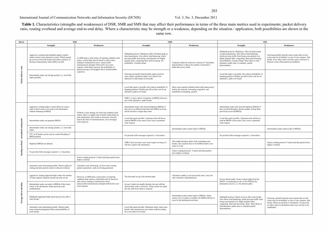
Table 1. Characteristics (strengths and weaknesses) of DSR, SMR and SMS that may affect their performance in terms of the three main metrics used in experiments; packet delivery ratio, routing overhead and average end-to-end delay. Where a characteristic may be strength or a weakness, depending on the situation / application, both possibilities are shown in the
same row.
Metric DSR SMR SMS
Strengths Weaknesses Strengths Weaknesses Strengths Weaknesses
Aggressive caching and multipath support enables nodes to know more alternative routes. Which speeds up recovery from link breaks and reduces chances of having to drop packets when buffers are full.
Multipath protocol. Minimizes effect of broken path on data transmission. Also allows load balancing, which prevents traffic from being concentrated over highly popular links, congesting them and increasing the probability of packet drops.
Multipath protocol. Minimizes effect of broken path on data transmission. Also allows load balancing, which prevents traffic from being concentrated over highly popular links, congesting them and increasing the probability of packet drops. More likely to find alternative paths since it considers partial disjointedness.
Selecting partially disjoint routes means that several routes may be invalidated at once if one common link breaks. If no other routes exist the source will have to find new route while packets are buffered.
Intermediate nodes can salvage packets, i.e. local link repair possible.
As DSR lacks a clear policy of expiring outdated cache entries, cached data may be based on stale routes, leading to transmission errors, unsuccessful retransmission attempts followed by new route requests. Such delays increase the probability of packets having to be dropped due to limited buffer capacities.
Selecting maximally disjoint paths makes protocol more robust; alternative path is less likely to be affected if a link breaks on first path.
Using the relatively restrictive criterion of "maximum disjointedness" reduces the number of alternative paths that can be found.
Local link repair is possible, this reduces probability of dropping packets if buffers get full as they wait for an alternative path to be found.
Local link repair is possible, this reduces probability of dropping packets if buffers get full as they wait for an alternative path to be found.
More route requests initiated which add (unnecessary) load to the network, increasing congestion and probability of dropping packets.
Pack
et d
eliv
ery
ratio
SMR-1 is more robust; it launches an RREQ whenever one of the alternative paths breaks.
Aggressive caching makes it more likely for source node to find a route in its cache to the destination without initiating an RREQ.
Intermediate nodes only forward duplicate RREQs if they arrive on different link than first RREQ received, and do not have a larger hop count.
Intermediate nodes only forward duplicate RREQs if they travelled through a shorter number of hops than previously-received RREQs.
Intermediate nodes can generate RREPs. Local link repair possible. Upstream node still has to send an RRER to the source, but it saves a potential route request.
Local link repair possible. Upstream node still has to send an RRER to the source, but it saves a potential route request.
Intermediate nodes can salvage packets, i.e. local link repair.
Without a clear strategy for removing outdated cache entries, there is a higher risk of nodes acting based on stale information, this results in increased network load in the form of retransmissions, error messages, route setup etc.
Intermediate nodes cannot reply to RREQs. Intermediate nodes cannot reply to RREQs.
TTL in IP header can be used to control flooding of RREQ packets. No periodic hello messages required i.e. beaconless. No periodic hello messages required i.e. beaconless.
Duplicate RREQs are deleted. SMR-2 does not start a new route request as long as it still has a path to the destination.
This might introduce delay if the remaining route breaks, since packets have to be buffered until a new route is set up.
Source routing protocol. Control and data packets have higher overhead.
No periodic hello messages required i.e. beaconless. Source routing protocol. Control and data packets have higher overhead.
Source routing protocol. Control and data packets have higher overhead.
Rou
ting
over
head
/ n
orm
aliz
ed r
outin
g lo
ad
Automatic route shortening possible. Shorter paths for routing and data packets result in reduced overhead.
Automatic route shortening involves more routing packets (gratuitous reply etc) being generated.
Aggressive caching approach helps reduce the number of route requests required; speeds up route set up. The first path set up is the shortest path. Alternative path(s) is not necessarily short, since the
only criterion is disjointed-ness.
Intermediate nodes can reply to RREQs if they know routes to the destination; helps speed up route establishment.
However, as DSR lacks a clear policy of expiring outdated cache entries, cached data may be based on stale routes, leading to transmission errors, unsuccessful retransmission attempts followed by new route requests.
In case 2 paths are equally disjoint, the one with the shortest hop count is selected. If hop counts are equal, the one with lower delay is selected.
Favors shorter paths. Source selects paths from the RREPs corresponding to the 1st few RREQs the destination receives, i.e. the shortest paths.
Multipath supported; helps speed up recovery after a route breaks.
Intermediate nodes cannot reply to RREQs, which means even if a path is available, the RREQ still has to travel to the destination and back.
Ave
rage
end
-to-
end
dela
y
Automatic route shortening possible. Shorter paths mean reduced propagation delay and probability of route breaks.
Local link repair possible. Minimizes delay when route breaks; data transmission can resume without waiting for a new path to be found.
Multipath protocol. Quick recovery after route breaks. Also allows load balancing, which prevents traffic from being concentrated over highly popular links, congesting them and increasing delay. More likely to find alternative paths since it considers partial disjointedness.
Selecting partially disjoint routes means that several routes may be invalidated at once if one common link breaks. Route set up delay is introduced if source has no other routes to destination and a new one has to be established.
204
International Journal of Communication Networks and Information Security (IJCNIS) Vol. 3, No. 3, December 2011
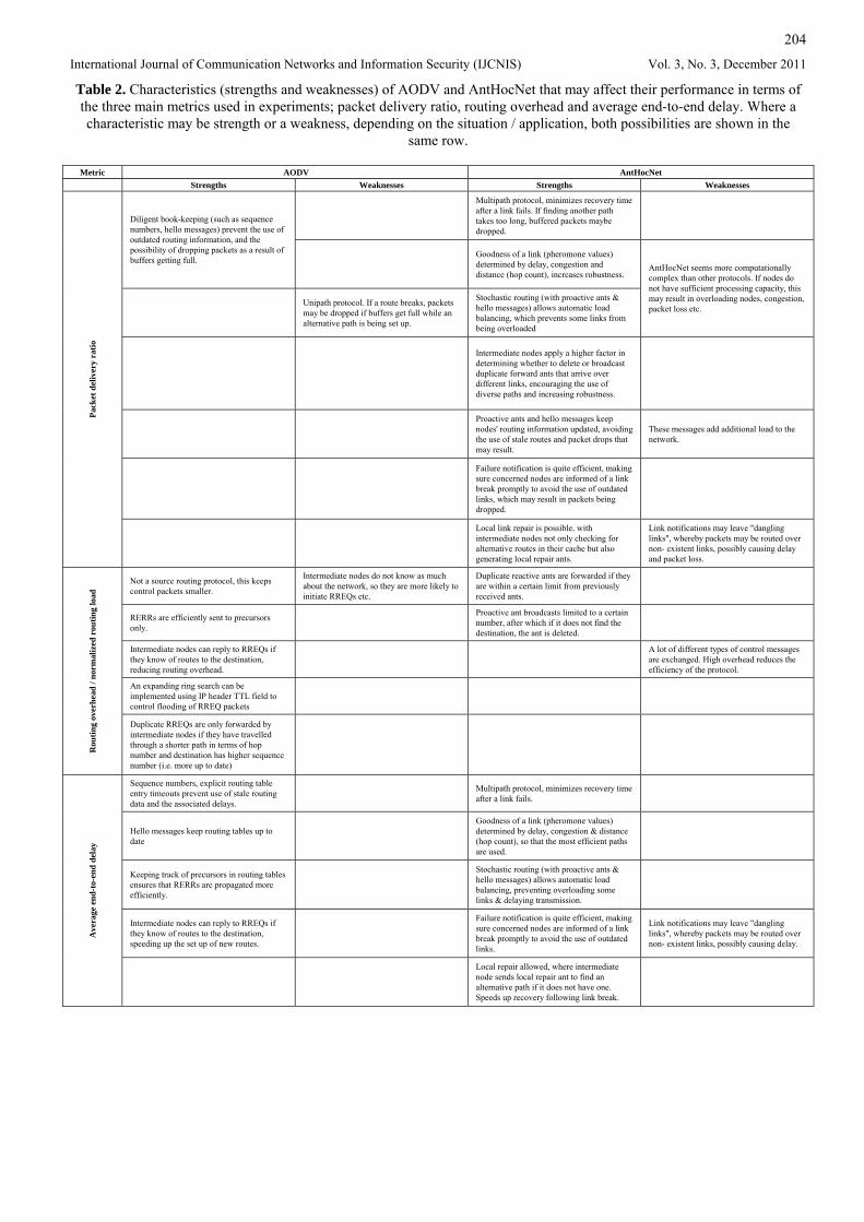
Table 2. Characteristics (strengths and weaknesses) of AODV and AntHocNet that may affect their performance in terms of the three main metrics used in experiments; packet delivery ratio, routing overhead and average end-to-end delay. Where a characteristic may be strength or a weakness, depending on the situation / application, both possibilities are shown in the
same row.
Metric AODV AntHocNet Strengths Weaknesses Strengths Weaknesses
Multipath protocol, minimizes recovery time after a link fails. If finding another path takes too long, buffered packets maybe dropped.
Diligent book-keeping (such as sequence numbers, hello messages) prevent the use of outdated routing information, and the possibility of dropping packets as a result of buffers getting full.
Goodness of a link (pheromone values) determined by delay, congestion and distance (hop count), increases robustness.
Unipath protocol. If a route breaks, packets may be dropped if buffers get full while an alternative path is being set up.
Stochastic routing (with proactive ants & hello messages) allows automatic load balancing, which prevents some links from being overloaded
AntHocNet seems more computationally complex than other protocols. If nodes do not have sufficient processing capacity, this may result in overloading nodes, congestion, packet loss etc.
Intermediate nodes apply a higher factor in determining whether to delete or broadcast duplicate forward ants that arrive over different links, encouraging the use of diverse paths and increasing robustness.
Proactive ants and hello messages keep nodes' routing information updated, avoiding the use of stale routes and packet drops that may result.
These messages add additional load to the network.
Failure notification is quite efficient, making sure concerned nodes are informed of a link break promptly to avoid the use of outdated links, which may result in packets being dropped.
Pack
et d
eliv
ery
ratio
Local link repair is possible, with intermediate nodes not only checking for alternative routes in their cache but also generating local repair ants.
Link notifications may leave "dangling links", whereby packets may be routed over non- existent links, possibly causing delay and packet loss.
Not a source routing protocol, this keeps control packets smaller.
Intermediate nodes do not know as much about the network, so they are more likely to initiate RREQs etc.
Duplicate reactive ants are forwarded if they are within a certain limit from previously received ants.
RERRs are efficiently sent to precursors only.
Proactive ant broadcasts limited to a certain number, after which if it does not find the destination, the ant is deleted.
Intermediate nodes can reply to RREQs if they know of routes to the destination, reducing routing overhead.
A lot of different types of control messages are exchanged. High overhead reduces the efficiency of the protocol.
An expanding ring search can be implemented using IP header TTL field to control flooding of RREQ packets
Rou
ting
over
head
/ no
rmal
ized
rou
ting
load
Duplicate RREQs are only forwarded by intermediate nodes if they have travelled through a shorter path in terms of hop number and destination has higher sequence number (i.e. more up to date)
Sequence numbers, explicit routing table entry timeouts prevent use of stale routing data and the associated delays.
Multipath protocol, minimizes recovery time after a link fails.
Hello messages keep routing tables up to date
Goodness of a link (pheromone values) determined by delay, congestion & distance (hop count), so that the most efficient paths are used.
Keeping track of precursors in routing tables ensures that RERRs are propagated more efficiently.
Stochastic routing (with proactive ants & hello messages) allows automatic load balancing, preventing overloading some links & delaying transmission.
Intermediate nodes can reply to RREQs if they know of routes to the destination, speeding up the set up of new routes.
Failure notification is quite efficient, making sure concerned nodes are informed of a link break promptly to avoid the use of outdated links.
Link notifications may leave "dangling links", whereby packets may be routed over non- existent links, possibly causing delay.
Ave
rage
end
-to-
end
dela
y
Local repair allowed, where intermediate node sends local repair ant to find an alternative path if it does not have one. Speeds up recovery following link break.
205
International Journal of Communication Networks and Information Security (IJCNIS) Vol. 3, No. 3, December 2011
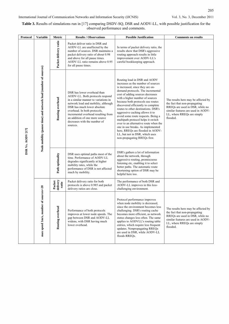
Table 3. Results of simulations run in [17] comparing DSDV-SQ, DSR and AODV-LL, with possible justification for the observed performance and comments.
Protocol Variable Metric Results / Observations Possible Justification Comments on results
Pack
et d
eliv
ery
ratio
Packet deliver ratio in DSR and AODV-LL are unaffected by the number of sources. DSR maintains a packet delivery ratio of about 0.98 and above for all pause times. AODV-LL ratio remains above 0.95 for all pause times.
In terms of packet delivery ratio, the results show that DSR's aggressive routing approach results in little improvement over AODV-LL's careful bookkeeping approach.
R
outin
g ov
erhe
ad
DSR has lower overhead than AODV-LL. Both protocols respond in a similar manner to variations in network load and mobility, although DSR has much lower absolute overhead. In both protocols, incremental overhead resulting from an addition of one more source decreases with the number of sources.
Routing load in DSR and AODV increases as the number of sources is increased, since they are on-demand protocols. The incremental cost of adding sources decreases with a higher number of sources because both protocols use routes discovered efficiently to complete routes to other destinations. DSR's aggressive caching allows it to avoid some route requests. Being a multipath protocol helps it switch over to an alternative route when the one in use breaks. As implemented here, RREQs are flooded in AODV-LL, but not in DSR, which uses non-propagating RREQs first.
The results here may be affected by the fact that non-propagating RREQs are used in DSR, while no similar features are used in AODV-LL, where RREQs are simply flooded.
Nod
e m
obili
ty (p
ause
tim
e) a
nd n
etw
ork
load
(num
ber
of so
urce
s)
Path
opt
imal
ity
DSR uses optimal paths most of the time. Performance of AODV-LL degrades significantly at higher mobility rates, while the performance of DSR is not affected much by mobility.
DSR's gathers a lot of information about the network, through aggressive routing, promiscuous listening etc, enabling it to select better paths. The automatic route shortening option of DSR may be helpful here too.
Pack
et
deliv
ery
ratio
Packet delivery ratio for both protocols is above 0.985 and packet delivery ratios are close.
The performance of both DSR and AODV-LL improves in this less-challenging environment.
DSR
Vs.
AO
DV
[17]
max
spee
d 1m
/s, n
umbe
r of
sour
ces=
20
Rou
ting
over
head
Performance of both protocols improves at lower node speeds. The gap between DSR and AODV-LL widens, with DSR having much lower overhead.
Protocol performance improves when node mobility is decreased, since the environment becomes less challenging. DSR's routing cache becomes more efficient, as network status changes less often. The same applies to AODVLL's routing table entries, which require less frequent updates. Nonpropagating RREQs are used in DSR, while AODV-LL floods RREQs.
The results here may be affected by the fact that non-propagating RREQs are used in DSR, while no similar features are used in AODV-LL, where RREQs are simply flooded.
206
International Journal of Communication Networks and Information Security (IJCNIS) Vol. 3, No. 3, December 2011
4.1.1 Notes on protocol implementation The implementation of AODV is referred to as AODV-LL, since it only relies on link layer feedback in 802.11, i.e. it does not use periodic Hello messages. AODV-LL also uses a RREP_WAIT_TIME of 6 seconds instead of 120 seconds as specified in [11]. As reported in [17], these modifications were found to improve performance.
4.1.2 Notes on simulation results As indicated in Table 3, AODV-LL as implemented in the simulations does not use expanding ring search, which was later specified in [11] to control the flooding of RREQs, while DSR source nodes use the TTL field in the IP header to send out non-propagating RREQ to their neighbors first to see if they have routes to the destination. If they don’t a propagating RREQ is used. This helps keep routing overhead low. Enabling the expanding ring search feature in AODV is expected to reduce its routing overhead.
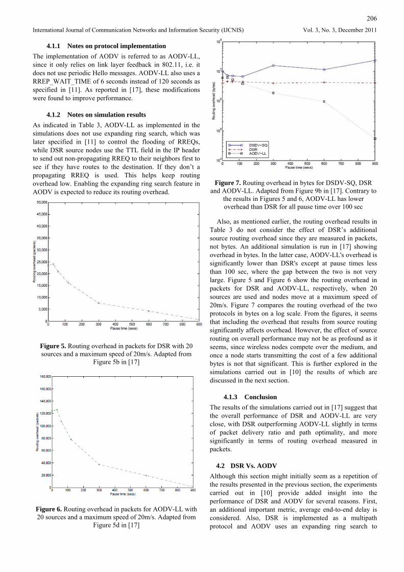
Figure 5. Routing overhead in packets for DSR with 20 sources and a maximum speed of 20m/s. Adapted from
Figure 5b in [17]
Figure 6. Routing overhead in packets for AODV-LL with 20 sources and a maximum speed of 20m/s. Adapted from
Figure 5d in [17]
Figure 7. Routing overhead in bytes for DSDV-SQ, DSR and AODV-LL. Adapted from Figure 9b in [17]. Contrary to
the results in Figures 5 and 6, AODV-LL has lower overhead than DSR for all pause time over 100 sec
Also, as mentioned earlier, the routing overhead results in Table 3 do not consider the effect of DSR’s additional source routing overhead since they are measured in packets, not bytes. An additional simulation is run in [17] showing overhead in bytes. In the latter case, AODV-LL's overhead is significantly lower than DSR's except at pause times less than 100 sec, where the gap between the two is not very large. Figure 5 and Figure 6 show the routing overhead in packets for DSR and AODV-LL, respectively, when 20 sources are used and nodes move at a maximum speed of 20m/s. Figure 7 compares the routing overhead of the two protocols in bytes on a log scale. From the figures, it seems that including the overhead that results from source routing significantly affects overhead. However, the effect of source routing on overall performance may not be as profound as it seems, since wireless nodes compete over the medium, and once a node starts transmitting the cost of a few additional bytes is not that significant. This is further explored in the simulations carried out in [10] the results of which are discussed in the next section.
4.1.3 Conclusion The results of the simulations carried out in [17] suggest that the overall performance of DSR and AODV-LL are very close, with DSR outperforming AODV-LL slightly in terms of packet delivery ratio and path optimality, and more significantly in terms of routing overhead measured in packets.
4.2 DSR Vs. AODV Although this section might initially seem as a repetition of the results presented in the previous section, the experiments carried out in [10] provide added insight into the performance of DSR and AODV for several reasons. First, an additional important metric, average end-to-end delay is considered. Also, DSR is implemented as a multipath protocol and AODV uses an expanding ring search to
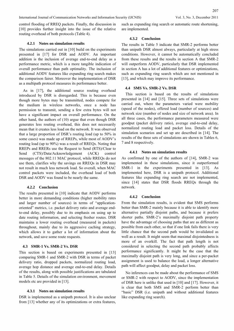
207
International Journal of Communication Networks and Information Security (IJCNIS) Vol. 3, No. 3, December 2011
control flooding of RREQ packets. Finally, the discussion in [10] provides further insight into the issue of the relative routing overhead of both protocols (Table 4).
4.2.1 Notes on simulation results The simulations carried out in [10] build on the experiments presented in [17] for DSR and AODV. An important addition is the inclusion of average end-to-end delay as a performance metric, which is a more tangible indication of overall performance than path optimality. The inclusion of additional AODV features like expanding ring search makes the comparison fairer. Moreover the implementation of DSR as a multipath protocol measures its performance better.
As in [17], the additional source routing overhead introduced by DSR is disregarded. This is because even though more bytes may be transmitted, nodes compete for the medium in wireless networks, once a node has permission to transmit, sending a few extra bytes will not have a significant impact on overall performance. On the other hand, the authors of (10) argue that even though DSR generates less routing overhead, this does not necessarily mean that it creates less load on the network. It was observed that a large proportion of DSR’s routing load (up to 50% in some cases) was made up of RREPs, while most of AODV’s routing load (up to 90%) was a result of RREQs. Noting that RREPs and RRERs use the Request to Send (RTS)/Clear to Send (CTS)/Data/Acknowledgement (ACK) control messages of the 802.11 MAC protocol, while RREQs do not use them, clarifies why the savings on RREQs in DSR may not result in much less network load. So overall, when MAC control packets were included, the overhead load of both DSR and AODV was found to be nearly the same.
4.2.2 Conclusion The results presented in [10] indicate that AODV performs better in more demanding conditions (higher mobility rates and larger number of sources) in terms of “application-oriented” metrics, i.e. packet delivery ratio and average end-to-end delay, possibly due to its emphasis on using up to date routing information, and selecting fresher routes. DSR maintains a lower routing overhead (measured in packets) throughout, mainly due to its aggressive caching strategy, which allows it to gather a lot of information about the network, and save some route requests.
4.3 SMR-1 Vs. SMR-2 Vs. DSR This section is based on experiments presented in [13] comparing SMR-1 and SMR-2 with DSR in terms of packet delivery ratio, dropped packets, normalized routing load, average hop distance and average end-to-end delay. Details of the results, along with possible justifications are tabulated in Table 5. Details of the simulation environment, movement models etc are provided in [13].
4.3.1 Notes on simulation results DSR is implemented as a unipath protocol. It is also unclear from [13] whether any of its optimizations or extra features,
such as expanding ring search or automatic route shortening, are implemented.
4.3.2 Conclusion The results in Table 5 indicate that SMR-2 performs better than unipath DSR almost always, particularly at high stress conditions. However, it cannot be automatically concluded from these results and the results in section A that SMR-2 will outperform AODV, particularly that DSR implemented in section A has a lot of additional features or optimizations, such as expanding ring search which are not mentioned in [13], and which may improve its performance.
4.4 SMS Vs. SMR-2 Vs. DSR This section is based on the results of simulations
presented in [14] and [15]. Three sets of simulations were carried out, where the parameters varied were mobility (speed of the nodes), offered load (number of sources) and network size (number of nodes and size of network area). In all three cases, the performance parameters measured were goodput (packet delivery ratio), average end-to-end delay, normalized routing load and packet loss. Details of the simulation scenarios and set up are described in [14]. The results of the three sets of simulations are shown in Tables 6, 7 and 8 respectively.
4.4.1 Notes on simulation results As confirmed by one of the authors of [14], SMR-2 was implemented in these simulations, since it outperformed SMR-1 in the experiments presented in [13]. As implemented here, DSR is a unipath protocol. Additional features like expanding ring search are not implemented, since [14] states that DSR floods RREQs through the network.
4.4.2 Conclusion From the simulation results, is evident that SMS performs better than SMR-2 mainly because it is able to identify more alternative partially disjoint paths, and because it prefers shorter paths. SMR-2’s maximally disjoint path property have the advantage of choosing paths that are as different as possible from each other, so that if one link fails there is very little chance that the second path would be invalidated as well as a result. It might seem that maximal disjointedness is more of an overkill. The fact that path length is not considered in selecting the second path probably affects performance significantly. It might be the case that the maximally disjoint path is very long, and since a per-packet assignment is used to balance the load, a longer alternative path will affect goodput, delay and packet loss.
No inferences can be made about the performance of SMS or SMR-2 with respect to AODV, since the implementation of DSR here is unlike that used in [10] and [17]. However, it is clear that both SMS and SMR-2 perform better than “basic” DSR (i.e. unipath and without additional features like expanding ring search).
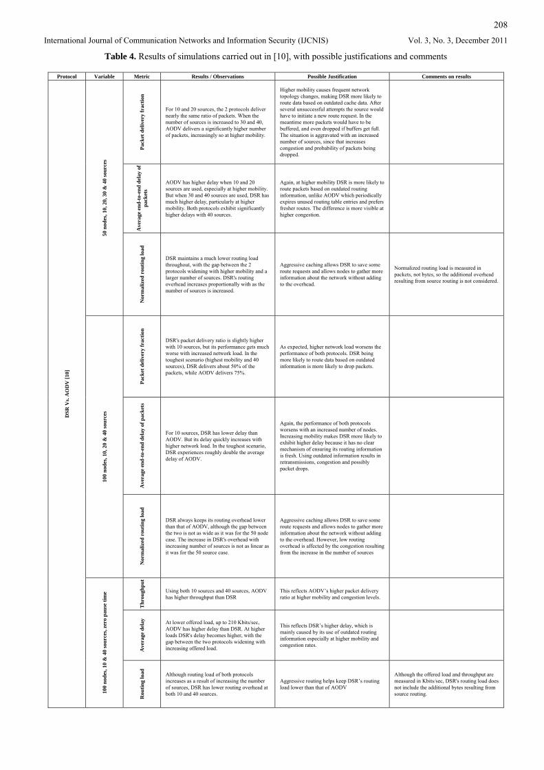
208
International Journal of Communication Networks and Information Security (IJCNIS) Vol. 3, No. 3, December 2011
Table 4. Results of simulations carried out in [10], with possible justifications and comments
Protocol Variable Metric Results / Observations Possible Justification Comments on results
Pack
et d
eliv
ery
frac
tion
For 10 and 20 sources, the 2 protocols deliver nearly the same ratio of packets. When the number of sources is increased to 30 and 40, AODV delivers a significantly higher number of packets, increasingly so at higher mobility.
Higher mobility causes frequent network topology changes, making DSR more likely to route data based on outdated cache data. After several unsuccessful attempts the source would have to initiate a new route request. In the meantime more packets would have to be buffered, and even dropped if buffers get full. The situation is aggravated with an increased number of sources, since that increases congestion and probability of packets being dropped.
Ave
rage
end
-to-
end
dela
y of
pa
cket
s
AODV has higher delay when 10 and 20 sources are used, especially at higher mobility. But when 30 and 40 sources are used, DSR has much higher delay, particularly at higher mobility. Both protocols exhibit significantly higher delays with 40 sources.
Again, at higher mobility DSR is more likely to route packets based on outdated routing information, unlike AODV which periodically expires unused routing table entries and prefers fresher routes. The difference is more visible at higher congestion.
50 n
odes
, 10,
20,
30
& 4
0 so
urce
s
Nor
mal
ized
rou
ting
load
DSR maintains a much lower routing load throughout, with the gap between the 2 protocols widening with higher mobility and a larger number of sources. DSR's routing overhead increases proportionally with as the number of sources is increased.
Aggressive caching allows DSR to save some route requests and allows nodes to gather more information about the network without adding to the overhead.
Normalized routing load is measured in packets, not bytes, so the additional overhead resulting from source routing is not considered.
Pack
et d
eliv
ery
frac
tion
DSR's packet delivery ratio is slightly higher with 10 sources, but its performance gets much worse with increased network load. In the toughest scenario (highest mobility and 40 sources), DSR delivers about 50% of the packets, while AODV delivers 75%.
As expected, higher network load worsens the performance of both protocols. DSR being more likely to route data based on outdated information is more likely to drop packets.
Ave
rage
end
-to-
end
dela
y of
pac
kets
For 10 sources, DSR has lower delay than AODV. But its delay quickly increases with higher network load. In the toughest scenario, DSR experiences roughly double the average delay of AODV.
Again, the performance of both protocols worsens with an increased number of nodes. Increasing mobility makes DSR more likely to exhibit higher delay because it has no clear mechanism of ensuring its routing information is fresh. Using outdated information results in retransmissions, congestion and possibly packet drops.
100
node
s, 10
, 20
& 4
0 so
urce
s
Nor
mal
ized
rou
ting
load
DSR always keeps its routing overhead lower than that of AODV, although the gap between the two is not as wide as it was for the 50 node case. The increase in DSR's overhead with increasing number of sources is not as linear as it was for the 50 source case.
Aggressive caching allows DSR to save some route requests and allows nodes to gather more information about the network without adding to the overhead. However, low routing overhead is affected by the congestion resulting from the increase in the number of sources
Thr
ough
put
Using both 10 sources and 40 sources, AODV has higher throughput than DSR
This reflects AODV’s higher packet delivery ratio at higher mobility and congestion levels.
Ave
rage
del
ay
At lower offered load, up to 210 Kbits/sec, AODV has higher delay than DSR. At higher loads DSR's delay becomes higher, with the gap between the two protocols widening with increasing offered load.
This reflects DSR’s higher delay, which is mainly caused by its use of outdated routing information especially at higher mobility and congestion rates.
DSR
Vs.
AO
DV
[10]
100
node
s, 10
& 4
0 so
urce
s, ze
ro p
ause
tim
e
Rou
ting
load
Although routing load of both protocols increases as a result of increasing the number of sources, DSR has lower routing overhead at both 10 and 40 sources.
Aggressive routing helps keep DSR’s routing load lower than that of AODV
Although the offered load and throughput are measured in Kbits/sec, DSR's routing load does not include the additional bytes resulting from source routing.
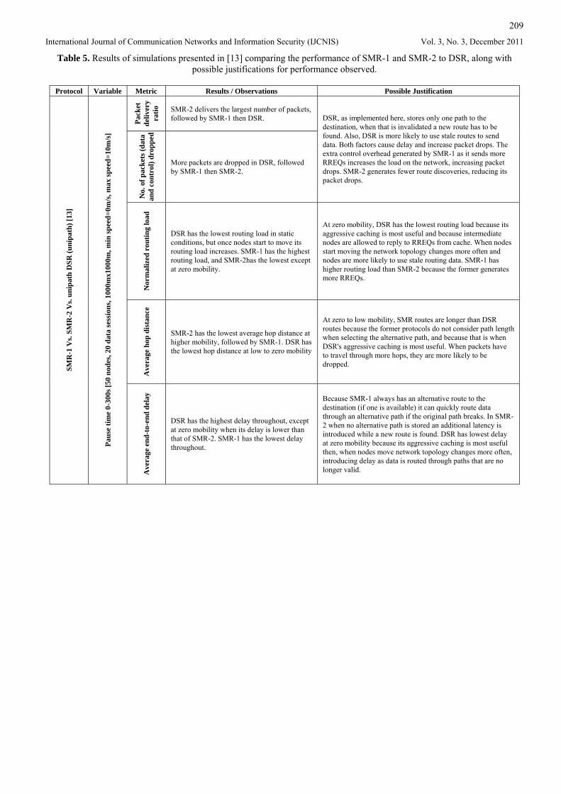
209
International Journal of Communication Networks and Information Security (IJCNIS) Vol. 3, No. 3, December 2011
Table 5. Results of simulations presented in [13] comparing the performance of SMR-1 and SMR-2 to DSR, along with possible justifications for performance observed.
Protocol Variable Metric Results / Observations Possible Justification
Pack
et
deliv
ery
ratio
SMR-2 delivers the largest number of packets, followed by SMR-1 then DSR.
No.
of p
acke
ts (d
ata
and
cont
rol)
drop
ped
More packets are dropped in DSR, followed by SMR-1 then SMR-2.
DSR, as implemented here, stores only one path to the destination, when that is invalidated a new route has to be found. Also, DSR is more likely to use stale routes to send data. Both factors cause delay and increase packet drops. The extra control overhead generated by SMR-1 as it sends more RREQs increases the load on the network, increasing packet drops. SMR-2 generates fewer route discoveries, reducing its packet drops.
Nor
mal
ized
rou
ting
load
DSR has the lowest routing load in static conditions, but once nodes start to move its routing load increases. SMR-1 has the highest routing load, and SMR-2has the lowest except at zero mobility.
At zero mobility, DSR has the lowest routing load because its aggressive caching is most useful and because intermediate nodes are allowed to reply to RREQs from cache. When nodes start moving the network topology changes more often and nodes are more likely to use stale routing data. SMR-1 has higher routing load than SMR-2 because the former generates more RREQs.
Ave
rage
hop
dis
tanc
e
SMR-2 has the lowest average hop distance at higher mobility, followed by SMR-1. DSR has the lowest hop distance at low to zero mobility
At zero to low mobility, SMR routes are longer than DSR routes because the former protocols do not consider path length when selecting the alternative path, and because that is when DSR's aggressive caching is most useful. When packets have to travel through more hops, they are more likely to be dropped. SM
R-1
Vs.
SMR
-2 V
s. un
ipat
h D
SR (u
nipa
th) [
13]
Paus
e tim
e 0-
300s
[50
node
s, 20
dat
a se
ssio
ns, 1
000m
x100
0m, m
in sp
eed=
0m/s
, max
spee
d=10
m/s
]
Ave
rage
end
-to-
end
dela
y
DSR has the highest delay throughout, except at zero mobility when its delay is lower than that of SMR-2. SMR-1 has the lowest delay throughout.
Because SMR-1 always has an alternative route to the destination (if one is available) it can quickly route data through an alternative path if the original path breaks. In SMR-2 when no alternative path is stored an additional latency is introduced while a new route is found. DSR has lowest delay at zero mobility because its aggressive caching is most useful then, when nodes move network topology changes more often, introducing delay as data is routed through paths that are no longer valid.
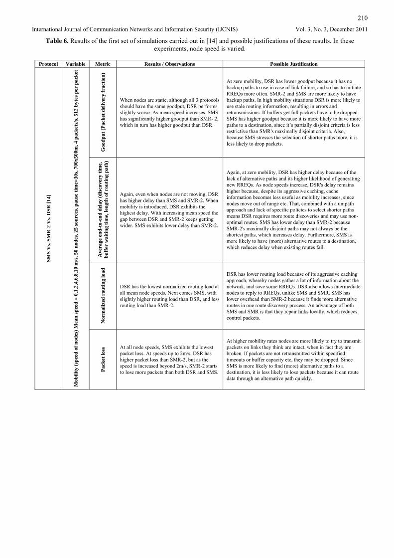
210
International Journal of Communication Networks and Information Security (IJCNIS) Vol. 3, No. 3, December 2011
Table 6. Results of the first set of simulations carried out in [14] and possible justifications of these results. In these experiments, node speed is varied.
Protocol Variable Metric Results / Observations Possible Justification
Goo
dput
(Pac
ket d
eliv
ery
frac
tion)
When nodes are static, although all 3 protocols should have the same goodput, DSR performs slightly worse. As mean speed increases, SMS has significantly higher goodput than SMR- 2, which in turn has higher goodput than DSR.
At zero mobility, DSR has lower goodput because it has no backup paths to use in case of link failure, and so has to initiate RREQs more often. SMR-2 and SMS are more likely to have backup paths. In high mobility situations DSR is more likely to use stale routing information, resulting in errors and retransmissions. If buffers get full packets have to be dropped. SMS has higher goodput because it is more likely to have more paths to a destination, since it’s partially disjoint criteria is less restrictive than SMR's maximally disjoint criteria. Also, because SMS stresses the selection of shorter paths more, it is less likely to drop packets.
Ave
rage
end
-to-
end
dela
y (d
isco
very
tim
e,
buff
er w
aitin
g tim
e, le
ngth
of r
outin
g pa
th)
Again, even when nodes are not moving, DSR has higher delay than SMS and SMR-2. When mobility is introduced, DSR exhibits the highest delay. With increasing mean speed the gap between DSR and SMR-2 keeps getting wider. SMS exhibits lower delay than SMR-2.
Again, at zero mobility, DSR has higher delay because of the lack of alternative paths and its higher likelihood of generating new RREQs. As node speeds increase, DSR's delay remains higher because, despite its aggressive caching, cache information becomes less useful as mobility increases, since nodes move out of range etc. That, combined with a unipath approach and lack of specific policies to select shorter paths means DSR requires more route discoveries and may use non-optimal routes. SMS has lower delay than SMR-2 because SMR-2's maximally disjoint paths may not always be the shortest paths, which increases delay. Furthermore, SMS is more likely to have (more) alternative routes to a destination, which reduces delay when existing routes fail.
Nor
mal
ized
rou
ting
load
DSR has the lowest normalized routing load at all mean node speeds. Next comes SMS, with slightly higher routing load than DSR, and less routing load than SMR-2.
DSR has lower routing load because of its aggressive caching approach, whereby nodes gather a lot of information about the network, and save some RREQs. DSR also allows intermediate nodes to reply to RREQs, unlike SMS and SMR. SMS has lower overhead than SMR-2 because it finds more alternative routes in one route discovery process. An advantage of both SMS and SMR is that they repair links locally, which reduces control packets.
SMS
Vs.
SMR
-2 V
s. D
SR [1
4]
Mob
ility
(spe
ed o
f nod
es) M
ean
spee
d =
0,1,
2,4,
6,8,
10 m
/s, 5
0 no
des,
25 so
urce
s, pa
use
time=
30s,
700x
500m
, 4 p
acke
ts/s
, 512
byt
es p
er p
acke
t
Pack
et lo
ss At all node speeds, SMS exhibits the lowest
packet loss. At speeds up to 2m/s, DSR has higher packet loss than SMR-2, but as the speed is increased beyond 2m/s, SMR-2 starts to lose more packets than both DSR and SMS.
At higher mobility rates nodes are more likely to try to transmit packets on links they think are intact, when in fact they are broken. If packets are not retransmitted within specified timeouts or buffer capacity etc, they may be dropped. Since SMS is more likely to find (more) alternative paths to a destination, it is less likely to lose packets because it can route data through an alternative path quickly.
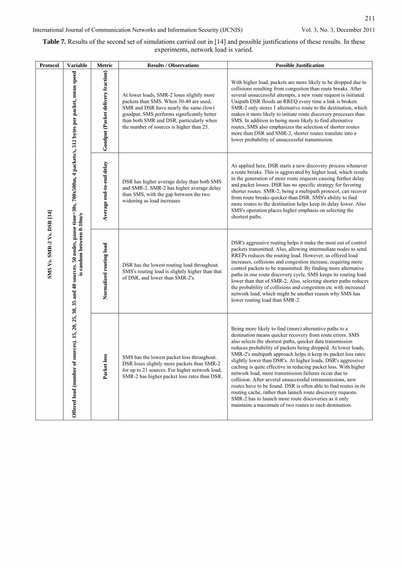
211
International Journal of Communication Networks and Information Security (IJCNIS) Vol. 3, No. 3, December 2011
Table 7. Results of the second set of simulations carried out in [14] and possible justifications of these results. In these experiments, network load is varied.
Protocol Variable Metric Results / Observations Possible Justification
Goo
dput
(Pac
ket d
eliv
ery
frac
tion)
At lower loads, SMR-2 loses slightly more packets than SMS. When 30-40 are used, SMR and DSR have nearly the same (low) goodput. SMS performs significantly better than both SMR and DSR, particularly when the number of sources is higher than 25.
With higher load, packets are more likely to be dropped due to collisions resulting from congestion than route breaks. After several unsuccessful attempts, a new route request is initiated. Unipath DSR floods an RREQ every time a link is broken. SMR-2 only stores 1 alternative route to the destination, which makes it more likely to initiate route discovery processes than SMS. In addition to being more likely to find alternative routes, SMS also emphasizes the selection of shorter routes more than DSR and SMR-2, shorter routes translate into a lower probability of unsuccessful transmission.
Ave
rage
end
-to-
end
dela
y
DSR has higher average delay than both SMS and SMR-2. SMR-2 has higher average delay than SMS, with the gap between the two widening as load increases
As applied here, DSR starts a new discovery process whenever a route breaks. This is aggravated by higher load, which results in the generation of more route requests causing further delay and packet losses. DSR has no specific strategy for favoring shorter routes. SMR-2, being a multipath protocol, can recover from route breaks quicker than DSR. SMS's ability to find more routes to the destination helps keep its delay lower. Also SMS's operation places higher emphasis on selecting the shortest paths.
Nor
mal
ized
rou
ting
load
DSR has the lowest routing load throughout. SMS's routing load is slightly higher than that of DSR, and lower than SMR-2's.
DSR's aggressive routing helps it make the most out of control packets transmitted. Also, allowing intermediate nodes to send RREPs reduces the routing load. However, as offered load increases, collisions and congestion increase, requiring more control packets to be transmitted. By finding more alternative paths in one route discovery cycle, SMS keeps its routing load lower than that of SMR-2. Also, selecting shorter paths reduces the probability of collisions and congestion etc with increased network load, which might be another reason why SMS has lower routing load than SMR-2.
SMS
Vs.
SMR
-2 V
s. D
SR [1
4]
Off
ered
load
(num
ber
of so
urce
s). 1
5, 2
0, 2
5, 3
0, 3
5 an
d 40
sour
ces.
50 n
odes
, pau
se ti
me=
30s,
700x
500m
, 4 p
acke
ts/s
, 512
byt
es p
er p
acke
t, m
ean
spee
d is
ran
dom
bet
wee
n 0-
10m
/s
Pack
et lo
ss
SMS has the lowest packet loss throughout. DSR loses slightly more packets than SMR-2 for up to 21 sources. For higher network load, SMR-2 has higher packet loss rates than DSR.
Being more likely to find (more) alternative paths to a destination means quicker recovery from route errors. SMS also selects the shortest paths, quicker data transmission reduces probability of packets being dropped. At lower loads, SMR-2's multipath approach helps it keep its packet loss rates slightly lower than DSR's. At higher loads, DSR's aggressive caching is quite effective in reducing packet loss. With higher network load, more transmission failures occur due to collision. After several unsuccessful retransmissions, new routes have to be found. DSR is often able to find routes in its routing cache, rather than launch route discovery requests. SMR-2 has to launch more route discoveries as it only maintains a maximum of two routes to each destination.
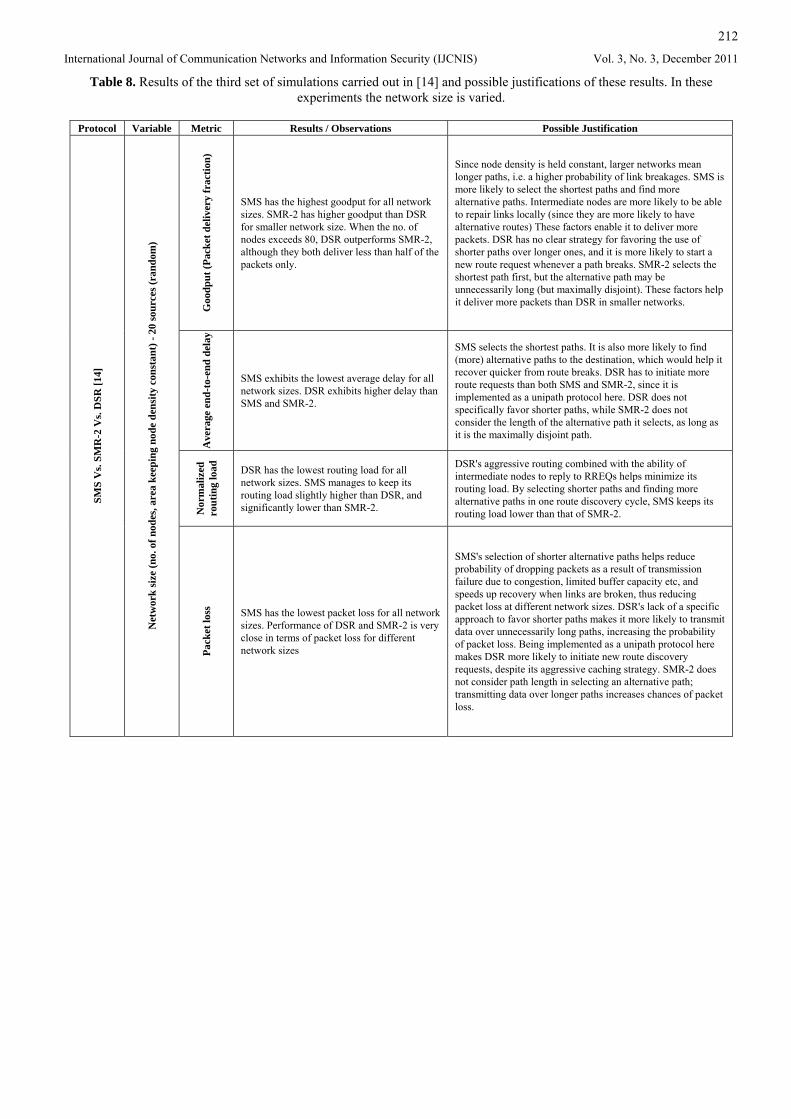
212
International Journal of Communication Networks and Information Security (IJCNIS) Vol. 3, No. 3, December 2011
Table 8. Results of the third set of simulations carried out in [14] and possible justifications of these results. In these experiments the network size is varied.
Protocol Variable Metric Results / Observations Possible Justification
Goo
dput
(Pac
ket d
eliv
ery
frac
tion)
SMS has the highest goodput for all network sizes. SMR-2 has higher goodput than DSR for smaller network size. When the no. of nodes exceeds 80, DSR outperforms SMR-2, although they both deliver less than half of the packets only.
Since node density is held constant, larger networks mean longer paths, i.e. a higher probability of link breakages. SMS is more likely to select the shortest paths and find more alternative paths. Intermediate nodes are more likely to be able to repair links locally (since they are more likely to have alternative routes) These factors enable it to deliver more packets. DSR has no clear strategy for favoring the use of shorter paths over longer ones, and it is more likely to start a new route request whenever a path breaks. SMR-2 selects the shortest path first, but the alternative path may be unnecessarily long (but maximally disjoint). These factors help it deliver more packets than DSR in smaller networks.
Ave
rage
end
-to-
end
dela
y
SMS exhibits the lowest average delay for all network sizes. DSR exhibits higher delay than SMS and SMR-2.
SMS selects the shortest paths. It is also more likely to find (more) alternative paths to the destination, which would help it recover quicker from route breaks. DSR has to initiate more route requests than both SMS and SMR-2, since it is implemented as a unipath protocol here. DSR does not specifically favor shorter paths, while SMR-2 does not consider the length of the alternative path it selects, as long as it is the maximally disjoint path.
Nor
mal
ized
ro
utin
g lo
ad
DSR has the lowest routing load for all network sizes. SMS manages to keep its routing load slightly higher than DSR, and significantly lower than SMR-2.
DSR's aggressive routing combined with the ability of intermediate nodes to reply to RREQs helps minimize its routing load. By selecting shorter paths and finding more alternative paths in one route discovery cycle, SMS keeps its routing load lower than that of SMR-2.
SMS
Vs.
SMR
-2 V
s. D
SR [1
4]
Net
wor
k si
ze (n
o. o
f nod
es, a
rea
keep
ing
node
den
sity
con
stan
t) -
20 so
urce
s (ra
ndom
)
Pack
et lo
ss
SMS has the lowest packet loss for all network sizes. Performance of DSR and SMR-2 is very close in terms of packet loss for different network sizes
SMS's selection of shorter alternative paths helps reduce probability of dropping packets as a result of transmission failure due to congestion, limited buffer capacity etc, and speeds up recovery when links are broken, thus reducing packet loss at different network sizes. DSR's lack of a specific approach to favor shorter paths makes it more likely to transmit data over unnecessarily long paths, increasing the probability of packet loss. Being implemented as a unipath protocol here makes DSR more likely to initiate new route discovery requests, despite its aggressive caching strategy. SMR-2 does not consider path length in selecting an alternative path; transmitting data over longer paths increases chances of packet loss.
213
International Journal of Communication Networks and Information Security (IJCNIS) Vol. 3, No. 3, December 2011
4.5 AntHocNet Vs. AODV This section is based on experiments carried out in [16]. Two sets of simulations are carried out; in the first, a sparse network is used where 100 nodes move within an area of 3000x1000m2 and both the random way point model and Gauss-Markov model are used. In the second set, the number of nodes and network areas are varied while keeping the overall network density constant. The setup of both sets of simulations is described in more detail in [16]. The performance metrics considered are packet delivery ratio, average end-to-end delay, delay jitter and routing overhead.
4.5.1 Sparse Network, random way point model Mobility is varied both by varying the speed at which nodes move and by varying the pause times. The results for varying node speeds are shown in Figures 8 and 9, while the results for varying pause times are shown in Figures 10 and 11. AntHocNet performs better than AODV in both cases in terms of packet delivery ratio, average-end-to-end delay and average delay jitter particularly at higher mobility levels. However, it generates much more routing overhead as a result of the different types of ants generated, and because it maintains paths proactively. Performance when speed is varied is as expected; it worsens with increasing speed. On the other hand, the results for varying pause times seem to be strange; performance is better at lower pause times (higher mobility). This seems to be a result of using a sparse network; when a node is out of range, at higher pause times it remains so for a longer time, increasing packet drops, delay, jitter and overhead.
4.5.2 Sparse Network, Gauss-Markov model Compared to the varying node speed results obtained with the random waypoint model, in the Gauss-Markov model packet delivery ratios decrease while delays increase, with AntHocNet outperforming AODV. Also, the gap between the two seems to widen. This indicates that AntHocNet’s learning approach allows it to exploit the inherent correlation in the node movements of the Gauss-Markov model. The results are shown in Figure 12.
4.5.3 Increasing network size, random waypoint model
The results in terms of packet delivery ratio and average end-to-end delay when the network size is varied as detailed in [16] are shown in Figure 13. In terms of packet delivery ratio, while AODV delivers slightly higher fraction of packets with the smallest network size (100 nodes), AntHocNet delivers more packets in larger networks, with the gap between the two widening as the network size is increased. In terms of average end-to-end delay AntHocNet has lower delay for all network sizes, with the gap widening between the two as the network size increases. This indicates that AntHocNet has good scalability as a result of its multipath approach, information gathering, link maintenance features etc.
4.5.4 Conclusion The above experiment results show that AntHocNet performs better than AODV in terms of packet delivery ratio, average end-to-end delay, and average jitter, but at the cost of higher routing overhead. It is also more scalable than AODV. However, it would be more challenging for AntHocNet, being an ant-based hybrid routing algorithm, to have its performance compared with another hybrid and/or ant-based routing protocol, to really see its strengths and weaknesses.
5. Conclusion and Future Work This paper started with an overview of MANET routing
protocols and their classification, followed by a detailed discussion of the operation and performance of selected protocols. The discussion started with DSR and AODV, which are two of the oldest and most popular reactive routing protocols designed for MANETs. Comparing DSR and AODV shows that although their performance is very close, each one of them has strengths and weaknesses which are visible depending on the network or application. This was followed by a discussion of the principles behind SMR, a source routing reactive protocol designed to improve on DSR. Next, the principles behind SMS, which was designed to improve on SMR, were presented. On comparing SMR and SMS, it is evident that SMS can outperform SMR in a lot of applications. Next, AntHocNet was discussed and compared to AODV. AntHocNet is a hybrid ant-based protocol, it is relatively complex in terms of processing requirements, and has higher overhead than AODV, but its performance in terms of packet delivery ratio and delay is much better in most scenarios. In conclusion, it is evident that each protocol has advantages and disadvantages and there is no one “best” routing protocol. Moreover, protocol characteristics that may be an advantage in one situation may also turn into a disadvantage in other situation. A clear example of that is DSR’s aggressive caching approach, which helps it gather a lot of information about the network, but can turn into a liability if the network topology changes too often. The same applies to the different types of ants used in AntHocNet, which usually strengthen the protocol, but can also increase overhead significantly.
As a next stage, it would be interesting to compare the performance of AntHocNet with that of other ant-based protocols, such as EARA-QoS and HOPNET.
Following a review of MANET routing protocols it is also important to note that in some situations routing may not always be advantageous and alternatives such as Key Based Broadcast Routing (KBBR) [18] may be more efficient, particularly in sensor networks. Another area with potential for future work is the design and implementation of simulations to compare the performance of KBBR to some of the popular routing protocols which may be used in sensor networks to help determine the type of situations in which routing would be beneficial, and when it would not be.
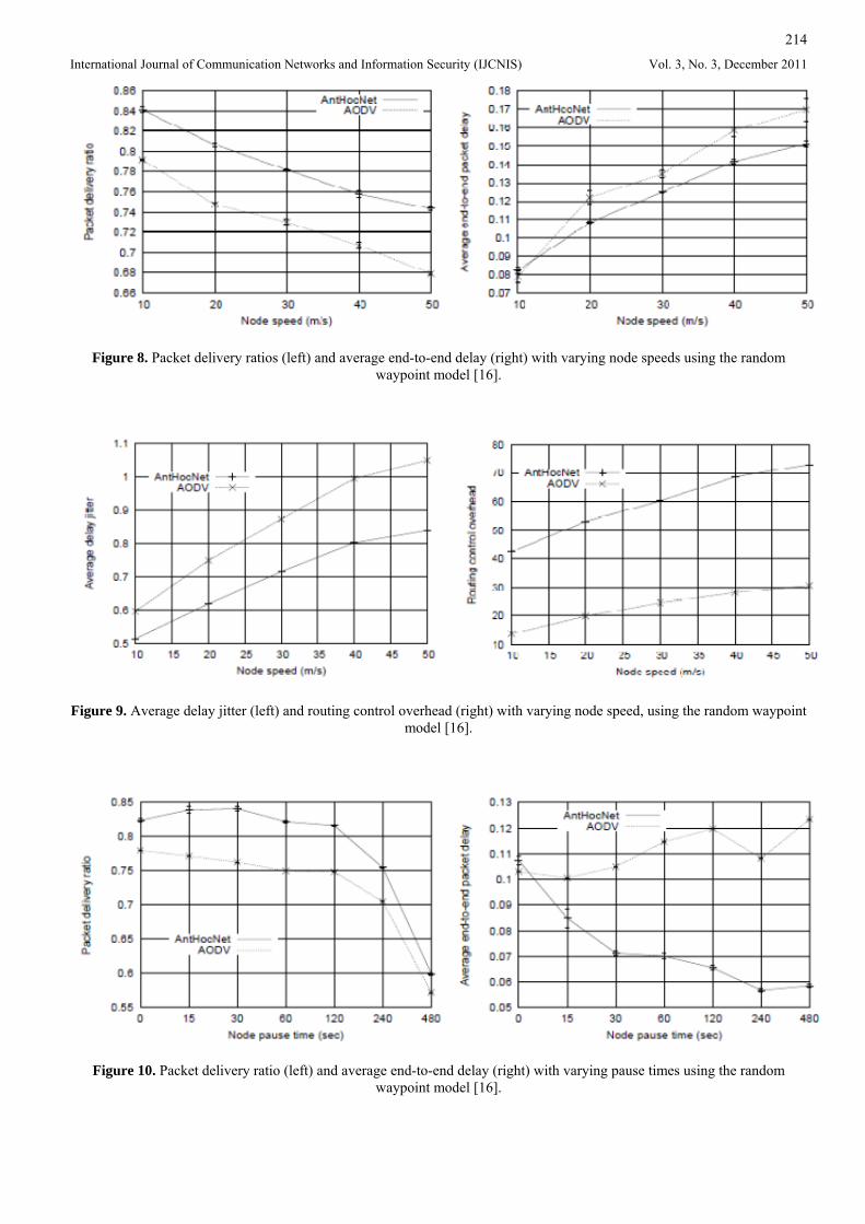
214
International Journal of Communication Networks and Information Security (IJCNIS) Vol. 3, No. 3, December 2011
Figure 8. Packet delivery ratios (left) and average end-to-end delay (right) with varying node speeds using the random waypoint model [16].
Figure 9. Average delay jitter (left) and routing control overhead (right) with varying node speed, using the random waypoint model [16].
Figure 10. Packet delivery ratio (left) and average end-to-end delay (right) with varying pause times using the random waypoint model [16].
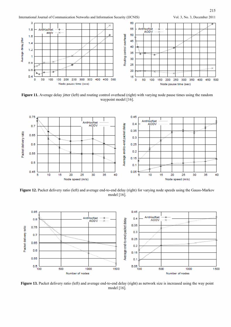
215
International Journal of Communication Networks and Information Security (IJCNIS) Vol. 3, No. 3, December 2011
Figure 11. Average delay jitter (left) and routing control overhead (right) with varying node pause times using the random waypoint model [16].
Figure 12. Packet delivery ratio (left) and average end-to-end delay (right) for varying node speeds using the Gauss-Markov model [16].
Figure 13. Packet delivery ratio (left) and average end-to-end delay (right) as network size is increased using the way point model [16].
216
International Journal of Communication Networks and Information Security (IJCNIS) Vol. 3, No. 3, December 2011
References [1] C.S. Murthy, B.S. Manoj, Ad hoc Wireless Networks
Architectures and Protocols, Prentice Hall, NJ, USA, 2004.
[2] A. Boukerche, Algorithms and Protocols for Wireless and Mobile Ad Hoc Networks. John Wiley & Sons, Inc., Hoboken, New Jersey, 2009.
[3] S. Basagni, M. Conti, S. Giordano, I. Stojmenovic, Mobile Ad Hoc Networking, John Wiley & Sons, Inc., Hoboken, New Jersey, 2004.
[4] L.M. Feeney, “A Taxonomy for Routing Protocols in Mobile Ad hoc Networks”, SICS Technical Report T99/07, October 1999.
[5] I. Chakeres, C.E. Perkins, “Dynamic MANET On-demand Routing Protocol (DYMO)”, Internet Draft <draft-ietf-manet-dymo-21.txt>, July 2010.
[6] Z. Liu, M. Kwiatkowska, C. Constantinou, “A Biologically Inspired QoS Routing Algorithm for Mobile Ad Hoc Networks”. International Journal of Wireless and Mobile Computing. vol. 4, no. 2, 2010, pp. 64–75.
[7] J. Wang, E. Osagie, P. Thulasiraman, R.K. Thulasiram, “HOPNET: A hybrid ant colony optimization routing algorithm for mobile ad hoc network”, Ad Hoc Networks, vol. 7, no. 4, June 2009, pp. 690–705.
[8] D.B. Johnson, Y. Hu, D.A. Maltz, “Dynamic Source Routing in Ad hoc Wireless Networks”, RFC 4728, February 2007.
[9] H. Zafar, D. Harle, I. Andonovic, M. Ashraf, “Performance Evaluation of On-demand Multipath Routing Protocols for Mobile Ad hoc Networks”, Proc. Seventh IASTED International Conference of Wireless & Optical Communications (WOC), Montreal, Canada, May 2007, pp. 325–329.
[10] S.R. Das, C.E. Perkins, E.M. Royer, “Performance comparison of two on-demand routing protocols for ad hoc networks”, Proc. INFOCOM 2000 Conference, Tel-Aviv, Israel, March 2000.
[11] C.E. Perkins, E.M. Royer, S. Das, “Ad hoc On-demand Distance Vector (AODV) Routing”, RFC 3561, July 2003.
[12] C.E. Perkins, Ad hoc Networking, Addison-Wesley, 2001.
[13] S. Lee, M. Gerla, “Split Multipath Routing with Maximally Disjoint Paths in Ad hoc Networks”, Proc. IEEE International Conference on Communication, Helsinki, June 2001, pp. 3201–3205.
[14] H. Zafar, D. Harle, I. Andonovic, Y. Khawaja, “Performance Evaluation of Shortest Multipath Source Routing Scheme”, IET Communications in Special Issue on Wireless Ad hoc Networks, vol. 3, no. 5, May 2009, pp. 700–713.
[15] H. Zafar, D. Harle, I. Andonovic, M. Ashraf, “SMS: Shortest Multipath Source Routing for Mobile Ad hoc Networks”, Proc. 2007 IEEE International Conference on Signal Processing and Communications (ICSPC), Dubai, UAE, November 2007, pp. 97–100.
[16] G. Di Caro, F. Ducatelle, L. Gambardella, “AntHocNet: An Adaptive Nature-inspired Algorithm for Routing in Mobile Ad Hoc Networks”, European Transactions on Telecommunications, vol. 15, no. 4, 2005.
[17] J. Broch, D.A. Maltz, D.B. Johnson, Y. Hu, J. Jetcheva, “A performance comparison of multi-hop wireless ad hoc network routing protocols”, Proc. Fourth Annual ACM/IEEE International Conference on Mobile Computing and Networking, Dallas, TX, October 1998, pp. 85–97.
[18] A.G. Jamieson, “A novel systems design approach to wireless sensor networks for industrial applications”, PhD. thesis, Department of Electrical & Electronic Engineering, University of Strathclyde, Glasgow, 2008.
[19] E. Spaho, L. Barolli, G. Mino, F. Xhafa, V. Kolici, R. Miho, “Implementation of CAVENET and its usage for performance evaluation of AODV, OLSR and DYMO protocols in vehicular networks”, Mobile Information Systems, vol. 6, no. 3, 2010, pp. 213–237.
[20] E. Kulla, M. Hiyama, M. Ikeda, L. Barolli, V. Kolici, R. Miho, “MANET performance for source and destination moving scenarios considering OLSR and AODV protocols”, Mobile Information Systems, vol. 6, no. 4, 2010, pp. 325–339.
[21] S. Misra, I. Woungang, S.C. Misra (Eds.), Guide to Wireless Ad Hoc Networks, Springer, 2009.
[22] N. Meghanathan, “Survey of Topology-based Multicast Routing Protocols for Mobile Ad hoc Networks”, International Journal of Communication Networks and Information Security (IJCNIS), vol. 3, no. 2, August 2011, pp. 124–137.


![Journal of Technology Survey of Routing Protocols for ... of Routing Protocols for... · Dynamic source routing protocol [7] is a reactive protocol. DSR requires no periodic updates](https://static.fdocuments.in/doc/165x107/5f37c487d286fb5893336dad/journal-of-technology-survey-of-routing-protocols-for-of-routing-protocols-for.jpg)