Survey o Modular Military Vehicles:...
26
Survey of Modular Military Vehicles: BENEFITS and BURDENS Jean M. Dasch and David J. Gorsich Modularity in military vehicle design is generally considered a positive attribute that promotes adaptability, resilience, and cost savings. The benefits and burdens of modularity are considered by studying historical programs dating back to World War II. Using a taxonomy developed at the U.S. Army Tank Automotive Research, Development and Engineering Center, vehicles were considered based on horizontal modularity, vertical modularity, and distributed modularity. Examples were given for each type, including the most extensive attempt at horizontal modularity in the 1980s, known as the Armored Family of Vehicles. Following these examples, various cost/benefit studies over the life cycle of the vehicle are reviewed with differing conclusions depending on the initial assumptions. Finally, a number of design factors are included that should be considered in any program on modular vehicles, as well as some recent initiatives that guide the path forward. Keywords: military vehicles, modularity, modular, armored family of vehicles (AFV), cost benefit
Transcript of Survey o Modular Military Vehicles:...
Survey of Modular Military Vehicles:
BENEFITS and BURDENS
Jean M. Dasch and David J. Gorsich
Modularity in military vehicle design is generally considered a positive attribute that promotes adaptability, resilience, and cost savings. The benefits and burdens of modularity are considered by studying historical programs dating back to World War II. Using a taxonomy developed at the U.S. Army Tank Automotive Research, Development and Engineering Center, vehicles were considered based on horizontal modularity, vertical modularity, and distributed modularity. Examples were given for each type, including the most extensive attempt at horizontal modularity in the 1980s, known as the Armored Family of Vehicles. Following these examples, various cost/benefit studies over the life cycle of the vehicle are reviewed with differing conclusions depending on the initial assumptions. Finally, a number of design factors are included that should be considered in any program on modular vehicles, as well as some recent initiatives that guide the path forward.
Keywords: military vehicles, modularity, modular, armored family of vehicles (AFV), cost benefit

lead image by Diane Fleischer
4 Defense ARJ, January 2016, Vol. 23 No. 1 : 2–27
A Publication of the Defense Acquisition University http://www.dau.mil
Modularity and adaptability are considered desirable, cost-saving attri-butes for military vehicles. Army Chief of Staff Raymond Odierno has stated that, “We need to become more agile, adaptable, and responsive to a wide variety” of threats (Ackerman, 2011, para. 9). Modularity also corresponds with an Army definition of a resilient system as one that “is easily adapted to many others through reconfiguration or replacement” (Holland, 2013, p. 3). Finally, the expected cost benefits fit well with the DoD initiative promoting Better Buying Power, which emphasizes the need for Modular Open Systems Architecture in program planning.
But the definition of modularity can cover a large design range. On one end of the spectrum, the purpose of modularity is to lower costs by using com-mon components or a common chassis over a number of vehicle variants. On the other end of the spectrum, modular vehicles are those that can be interchanged in theater to accomplish different purposes. Thus, modularity may have different end states/cost savings due to commonality or greater operational flexibility to perform multiple missions.
Past attempts at modularity since World War II will be reviewed throughout this article. Historically, modularity usually involved producing variants on a single chassis, defined as horizontal modularity in a subsequent section of this article. Newer attempts at modularity incorporate more ambitious designs that strive for agile and adaptable vehicles. Following the examples, past studies on the benefits and burdens of modularity over a vehicle’s life cycle will be reviewed.
The ultimate question of whether a new system should be modularized cannot be answered here due to the many variables at play. However, this article will lay out some of the past successes and failures, and provide design points for consideration. Finally, two current efforts to determine modularity benefits and burdens for specific scenarios will be described—one through a U.S. Army Tank Automotive Research, Development and Engineering Center (TARDEC)-sponsored Automotive Research Center (ARC) project, and the other through the Office of Naval Research (ONR).
Definitions of Modular SystemsAs mentioned earlier, modularity can include a wide range of vehicle
platforms that can fulfill a variety of missions. Modular vehicles might be considered the opposite of unique vehicles in which each vehicle is designed and built for a specific purpose. Somewhere between unique and modular
5Defense ARJ, January 2016, Vol. 23 No. 1 : 2–27
January 2016
lies the concept of commonality in which different vehicle platforms share common components. Commonality for military equipment was explored by a Rand Corporation study sponsored by the Army Capabilities Integration Center (Held, Newsome, & Lewis, 2008). As expected, commonality was found to be desirable, for it can increase operational flexibility and reduce procurement, logistical, and training burdens. But, perhaps less expected, it can also decrease design freedom and may increase costs due to excess functionality. So it is with modularity—the perceived benefits of modularity can sometimes be offset by the negative aspects.
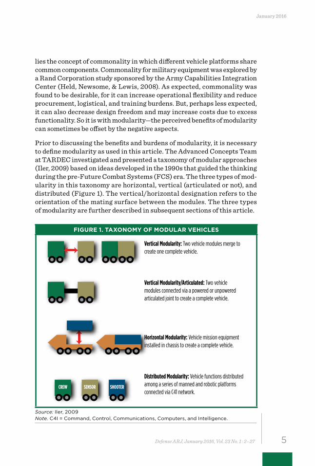
Prior to discussing the benefits and burdens of modularity, it is necessary to define modularity as used in this article. The Advanced Concepts Team at TARDEC investigated and presented a taxonomy of modular approaches (Iler, 2009) based on ideas developed in the 1990s that guided the thinking during the pre-Future Combat Systems (FCS) era. The three types of mod-ularity in this taxonomy are horizontal, vertical (articulated or not), and distributed (Figure 1). The vertical/horizontal designation refers to the orientation of the mating surface between the modules. The three types of modularity are further described in subsequent sections of this article.
FIGURE 1. TAXONOMY OF MODULAR VEHICLES
Vertical Modularity: Two vehicle modules merge to create one complete vehicle.
Vertical Modularity/Articulated: Two vehicle modules connected via a powered or unpowered articulated joint to create a complete vehicle.
Horizontal Modularity: Vehicle mission equipment installed in chassis to create a complete vehicle.
Distributed Modularity: Vehicle functions distributed among a series of manned and robotic platforms connected via C41 network.
CREW SENSOR SHOOTER
Source: Iler, 2009 Note. C4I = Command, Control, Communications, Computers, and Intelligence.
6 Defense ARJ, January 2016, Vol. 23 No. 1 : 2–27
A Publication of the Defense Acquisition University http://www.dau.mil
Horizontal Modularity (Family of Vehicles)
By far the most common form of modularity to date is that of horizontal modularity, also described as a Family of Vehicles (FOV). An FOV usually shares a common chassis including a powertrain, suspension, and wheels or tracks with a unique “box” on top consisting of associated mission-specific equipment. This type of modularity was used during World War II when the chassis from the M4 Sherman tank was used for self-propelled artillery, tank destroyers, and numerous tracked carriers (Hunnicutt, 1990, p. 281). Other examples include the M60 series of tanks and the M107, M108, M109, and M110 artillery systems in the 1950s. In general, the variants come from a production facility and are not interchangeable in theater. Probably the most ambitious examples of an entire FOV being designed simultaneously are the Armored Family of Vehicles (AFV) from the 1980s (Lopez, 1987) and the FCS from the 2000s.
Armored Family of Vehicles—1980sThe goal of the AFV was to have a common chassis and components
integrated with various mission modules. A minimum number of chassis and a maximum number of common system components were planned. “Reduction in cost will be achieved through modularity, component com-monality, and multiple systems capabilities combined so as to achieve required effectiveness with more survivable, cost-effective systems” (Sunell et al, 1987, p. VI–7). Army studies had indicated that using a common chas-sis and common components could reduce future operational and support (O&S) costs.
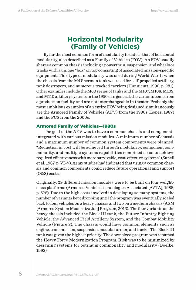
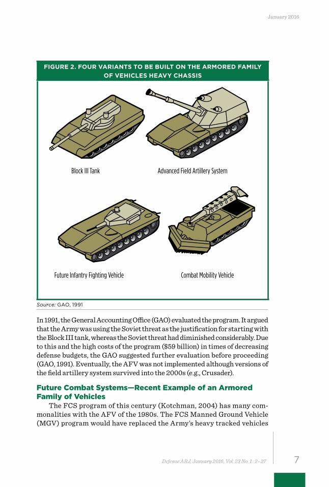
Originally, 29 different mission modules were to be built on four weight-class platforms (Armored Vehicle Technologies Associated [AVTA], 1988, p. 578). Due to the high costs involved in developing so many systems, the number of variants kept dropping until the program was eventually scaled back to four vehicles on a heavy chassis and two on a medium chassis (ASM [Armored System Modernization] Program, 2013). The four variants on the heavy chassis included the Block III tank, the Future Infantry Fighting Vehicle, the Advanced Field Artillery System, and the Combat Mobility Vehicle (Figure 2). The chassis would have common elements such as engine, transmission, suspension, modular armor, and tracks. The Block III tank was given the highest priority. The downsized program was renamed the Heavy Force Modernization Program. Risk was to be minimized by designing systems for optimum commonality and modularity (Boelke, 1992).
7Defense ARJ, January 2016, Vol. 23 No. 1 : 2–27
January 2016
FIGURE 2. FOUR VARIANTS TO BE BUILT ON THE ARMORED FAMILY OF VEHICLES HEAVY CHASSIS
Block III Tank Advanced Field Artillery System
Future Infantry Fighting Vehicle Combat Mobility Vehicle
Source: GAO, 1991
In 1991, the General Accounting Office (GAO) evaluated the program. It argued that the Army was using the Soviet threat as the justification for starting with the Block III tank, whereas the Soviet threat had diminished considerably. Due to this and the high costs of the program ($59 billion) in times of decreasing defense budgets, the GAO suggested further evaluation before proceeding (GAO, 1991). Eventually, the AFV was not implemented although versions of the field artillery system survived into the 2000s (e.g., Crusader).
Future Combat Systems—Recent Example of an Armored Family of Vehicles
The FCS program of this century (Kotchman, 2004) has many com-monalities with the AFV of the 1980s. The FCS Manned Ground Vehicle (MGV) program would have replaced the Army’s heavy tracked vehicles
8 Defense ARJ, January 2016, Vol. 23 No. 1 : 2–27
A Publication of the Defense Acquisition University http://www.dau.mil
developed in the 1960s and 1970s with lighter, more mobile combat vehi-cles. MGV included eight variants of tracked vehicles built on a common chassis: a mounted combat system, a reconnaissance and surveillance vehicle, a non-line-of-sight cannon, a non-line-of-sight mortar, a recovery and maintenance vehicle, an infantry carrier vehicle, a command and con-trol vehicle, and a medical vehicle. The common chassis included the crew station, propulsion, vetronics, and suspension. They touted commonality in development, training, maintenance, tools, logistics approach, production, and computing. In all, over 70 percent of the components were designed for commonality among the variants (Zanini, 2009).
As described in a RAND report, FCS was the “largest and most ambi-tious planned acquisition program in the Army’s history” (Pernin et al., 2012, p. xvii). However, in April 2009 then-Secretary of Defense Robert Gates cancelled most of the program. Many reasons have been given for the cancellation, which were captured in the RAND report and a subsequent Government Accountability Office (2009) report. As the vehicle weight increased from the original 19 to 30 tons due to increasing requirements, the common chassis had to be replaced with three different chassis. As with the 1980s’ program, the reasons for cancellation were not directly attributable to the modular approach.
Horizontal Modularity/Common Chassis—Vehicles in Production
Despite the cancellation of the ambitious AFV and the FCS programs, many other military vehicles have evolved into families, such as the Bradley, Abrams, Stryker, and many others (Science Applications International Corporation [SAIC], 2008). In most cases, the families were not planned from the outset, but rather a unique vehicle was designed and built for a single purpose. Later the original chassis was used for variants. This had the advantage of lower initial Research, Development, Testing and Evaluation (RDT&E) costs in that only requirements for a single vehicle needed to be considered rather than trying to design a chassis to fit many roles. On the downside, the original chassis might not meet the requirements for vehicles planned later. The following discussion cites four examples of horizontal modularity.
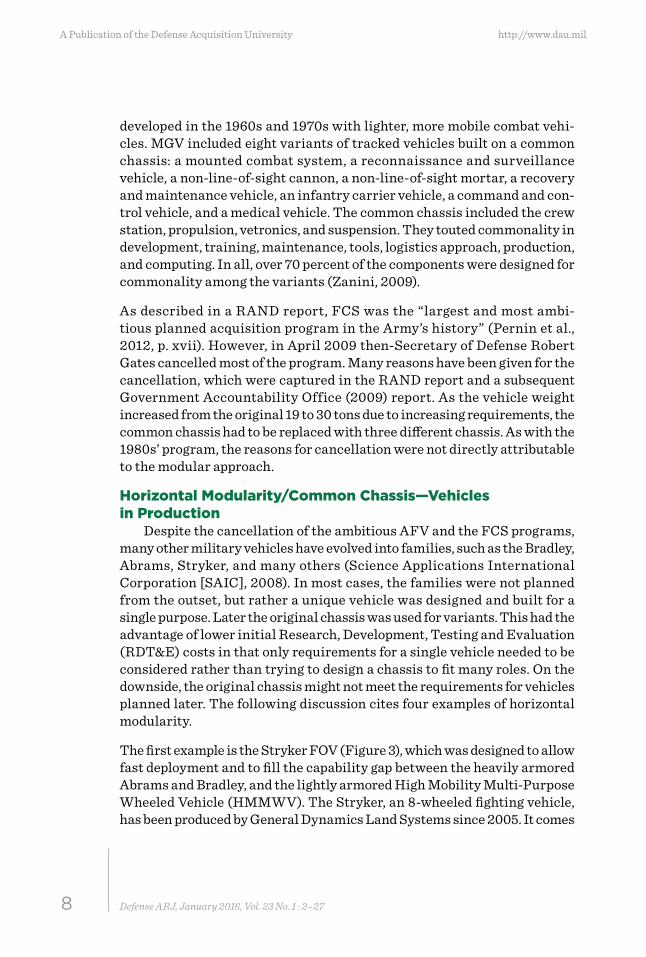
The first example is the Stryker FOV (Figure 3), which was designed to allow fast deployment and to fill the capability gap between the heavily armored Abrams and Bradley, and the lightly armored High Mobility Multi-Purpose Wheeled Vehicle (HMMWV). The Stryker, an 8-wheeled fighting vehicle, has been produced by General Dynamics Land Systems since 2005. It comes
9Defense ARJ, January 2016, Vol. 23 No. 1 : 2–27
January 2016
in several variants that share a common engine, transmission, hydraulics, wheels, tires, differential, and transfer case. Variants include an infantry carrier vehicle; a reconnaissance vehicle; a mobile gun system; a mortar carrier; a command vehicle; a fire support vehicle; an engineer squad vehi-cle; a medical evacuation vehicle; an anti-tank guided missile vehicle; and a nuclear, biological, and chemical reconnaissance vehicle (army-technology.com, n.d.; Stryker, 2015).
FIGURE 3. STRYKER
Source: Department of Defense
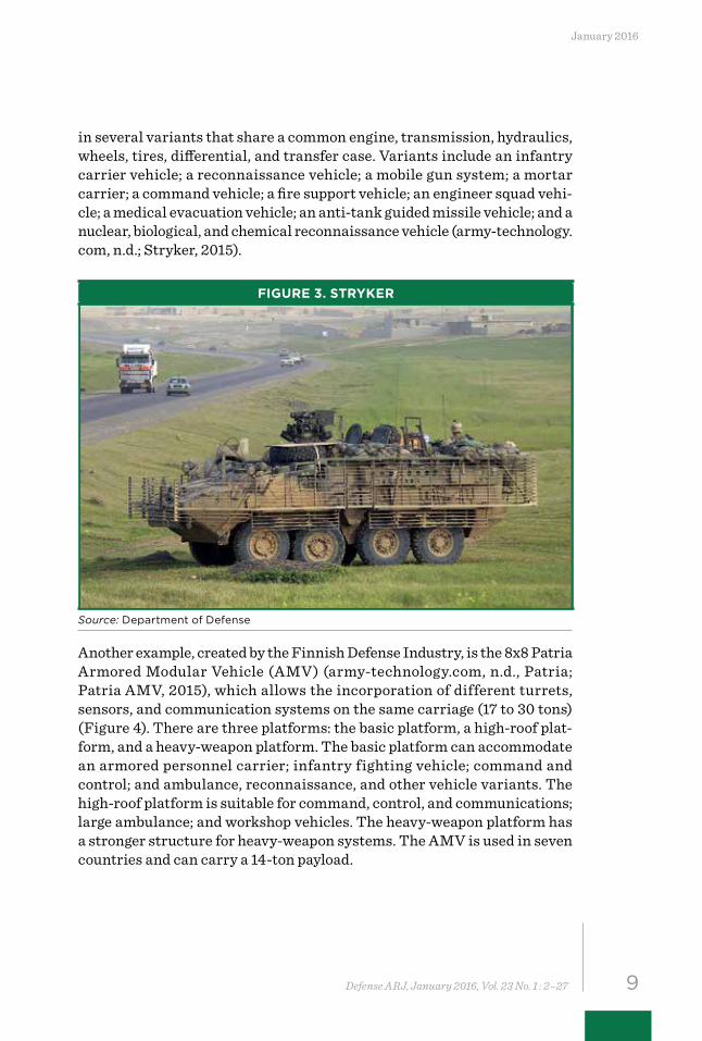
Another example, created by the Finnish Defense Industry, is the 8x8 Patria Armored Modular Vehicle (AMV) (army-technology.com, n.d., Patria; Patria AMV, 2015), which allows the incorporation of different turrets, sensors, and communication systems on the same carriage (17 to 30 tons) (Figure 4). There are three platforms: the basic platform, a high-roof plat-form, and a heavy-weapon platform. The basic platform can accommodate an armored personnel carrier; infantry fighting vehicle; command and control; and ambulance, reconnaissance, and other vehicle variants. The high-roof platform is suitable for command, control, and communications; large ambulance; and workshop vehicles. The heavy-weapon platform has a stronger structure for heavy-weapon systems. The AMV is used in seven countries and can carry a 14-ton payload.
10 Defense ARJ, January 2016, Vol. 23 No. 1 : 2–27
A Publication of the Defense Acquisition University http://www.dau.mil
FIGURE 4. PATRIA ARMORED MODULAR VEHICLE
Source: United States Navy
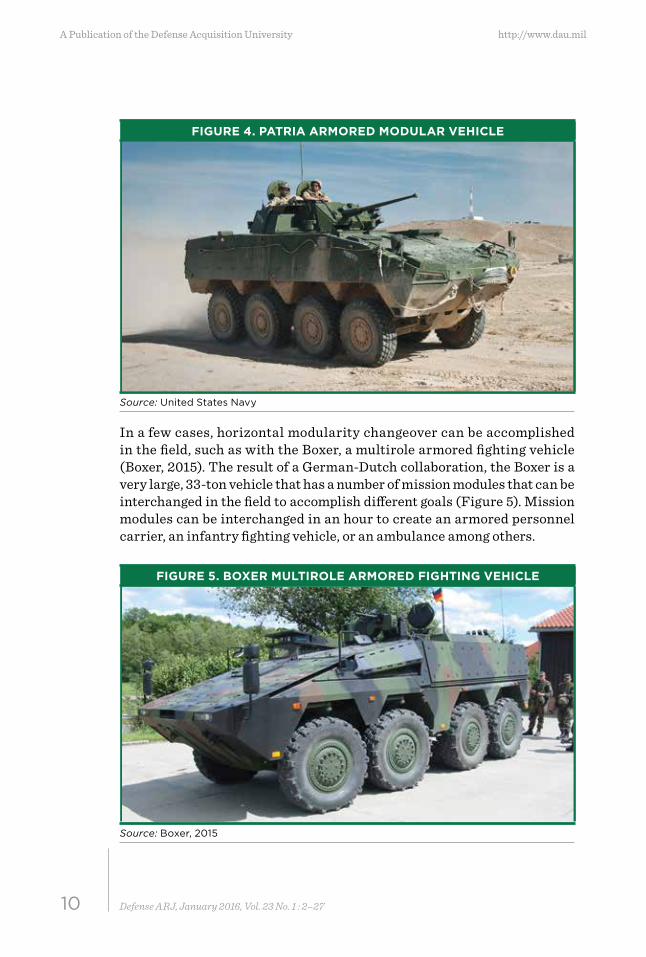
In a few cases, horizontal modularity changeover can be accomplished in the field, such as with the Boxer, a multirole armored fighting vehicle (Boxer, 2015). The result of a German-Dutch collaboration, the Boxer is a very large, 33-ton vehicle that has a number of mission modules that can be interchanged in the field to accomplish different goals (Figure 5). Mission modules can be interchanged in an hour to create an armored personnel carrier, an infantry fighting vehicle, or an ambulance among others.
FIGURE 5. BOXER MULTIROLE ARMORED FIGHTING VEHICLE
Source: Boxer, 2015
11Defense ARJ, January 2016, Vol. 23 No. 1 : 2–27
January 2016
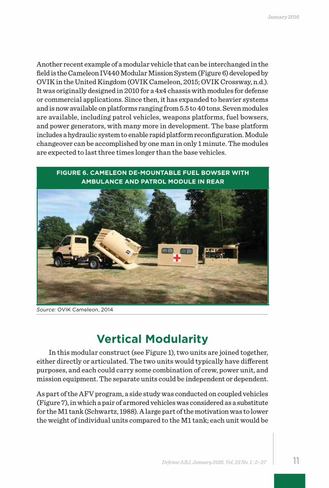
Another recent example of a modular vehicle that can be interchanged in the field is the Cameleon IV440 Modular Mission System (Figure 6) developed by OVIK in the United Kingdom (OVIK Cameleon, 2015; OVIK Crossway, n.d.). It was originally designed in 2010 for a 4x4 chassis with modules for defense or commercial applications. Since then, it has expanded to heavier systems and is now available on platforms ranging from 5.5 to 40 tons. Seven modules are available, including patrol vehicles, weapons platforms, fuel bowsers, and power generators, with many more in development. The base platform includes a hydraulic system to enable rapid platform reconfiguration. Module changeover can be accomplished by one man in only 1 minute. The modules are expected to last three times longer than the base vehicles.
FIGURE 6. CAMELEON DE-MOUNTABLE FUEL BOWSER WITH AMBULANCE AND PATROL MODULE IN REAR
Source: OVIK Cameleon, 2014
Vertical ModularityIn this modular construct (see Figure 1), two units are joined together,
either directly or articulated. The two units would typically have different purposes, and each could carry some combination of crew, power unit, and mission equipment. The separate units could be independent or dependent.
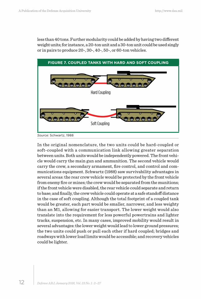
As part of the AFV program, a side study was conducted on coupled vehicles (Figure 7), in which a pair of armored vehicles was considered as a substitute for the M1 tank (Schwartz, 1988). A large part of the motivation was to lower the weight of individual units compared to the M1 tank; each unit would be
12 Defense ARJ, January 2016, Vol. 23 No. 1 : 2–27
A Publication of the Defense Acquisition University http://www.dau.mil
less than 40 tons. Further modularity could be added by having two different weight units; for instance, a 20-ton unit and a 30-ton unit could be used singly or in pairs to produce 20-, 30-, 40-, 50-, or 60-ton vehicles.
FIGURE 7. COUPLED TANKS WITH HARD AND SOFT COUPLING
Hard Coupling
Soft Coupling
Source: Schwartz, 1988
In the original nomenclature, the two units could be hard-coupled or soft-coupled with a communication link allowing greater separation between units. Both units would be independently powered. The front vehi-cle would carry the main gun and ammunition. The second vehicle would carry the crew, a secondary armament, fire control, and control and com-munications equipment. Schwartz (1988) saw survivability advantages in several areas: the rear crew vehicle would be protected by the front vehicle from enemy fire or mines; the crew would be separated from the munitions; if the front vehicle were disabled, the rear vehicle could separate and return to base; and finally, the crew vehicle could operate at a safe standoff distance in the case of soft coupling. Although the total footprint of a coupled tank would be greater, each part would be smaller, narrower, and less weighty than an M1, allowing for easier transport. The lower weight would also translate into the requirement for less powerful powertrains and lighter tracks, suspension, etc. In many cases, improved mobility would result in several advantages: the lower weight would lead to lower ground pressures; the two units could push or pull each other if hard coupled; bridges and roadways with lower load limits would be accessible; and recovery vehicles could be lighter.
13Defense ARJ, January 2016, Vol. 23 No. 1 : 2–27
January 2016
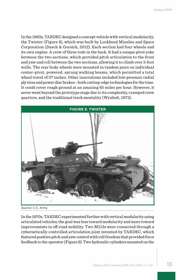
In the 1960s, TARDEC designed a concept vehicle with vertical modularity, the Twister (Figure 8), which was built by Lockheed Missiles and Space Corporation (Dasch & Gorsich, 2012). Each section had four wheels and its own engine. A crew of three rode in the back. It had a unique pivot yoke between the two sections, which provided pitch articulation to the front and yaw and roll between the two sections, allowing it to climb over 3-foot walls. The rear body wheels were mounted in tandem pairs on individual center-pivot, powered, sprung walking beams, which permitted a total wheel travel of 27 inches. Other innovations included low-pressure radial ply tires and power disc brakes—both cutting-edge technologies for the time. It could cover rough ground at an amazing 65 miles per hour. However, it never went beyond the prototype stage due to its complexity, cramped crew quarters, and the traditional track mentality (Wynbelt, 1972).
FIGURE 8. TWISTER
Source: U.S. Army
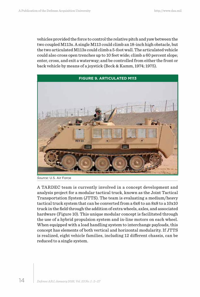
In the 1970s, TARDEC experimented further with vertical modularity using articulated vehicles; the goal was less toward modularity and more toward improvements in off-road mobility. Two M113s were connected through a cybernetically controlled articulation joint invented by TARDEC, which featured positive pitch and yaw control with roll freedom that provided force feedback to the operator (Figure 9). Two hydraulic cylinders mounted on the
14 Defense ARJ, January 2016, Vol. 23 No. 1 : 2–27
A Publication of the Defense Acquisition University http://www.dau.mil
vehicles provided the force to control the relative pitch and yaw between the two coupled M113s. A single M113 could climb an 18-inch high obstacle, but the two articulated M113s could climb a 5-foot wall. The articulated vehicle could also cross open trenches up to 10 feet wide; climb a 60 percent slope; enter, cross, and exit a waterway; and be controlled from either the front or back vehicle by means of a joystick (Beck & Kamm, 1974; 1975).
FIGURE 9. ARTICULATED M113
Source: U.S. Air Force
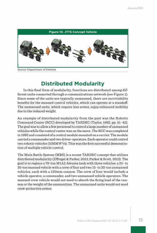
A TARDEC team is currently involved in a concept development and analysis project for a modular tactical truck, known as the Joint Tactical Transportation System (JTTS). The team is evaluating a medium/heavy tactical truck system that can be converted from a 6x6 to an 8x8 to a 10x10 truck in the field through the addition of extra wheels, axles, and associated hardware (Figure 10). This unique modular concept is facilitated through the use of a hybrid propulsion system and in-line motors on each wheel. When equipped with a load handling system to interchange payloads, this concept has elements of both vertical and horizontal modularity. If JTTS is realized, eight vehicle families, including 12 different chassis, can be reduced to a single system.
15Defense ARJ, January 2016, Vol. 23 No. 1 : 2–27
January 2016
Figure 10. JTTS Concept Vehicle
Source: Department of Defense
Distributed ModularityIn this final form of modularity, functions are distributed among dif-
ferent units connected through a communications network (see Figure 1). Since some of the units are typically unmanned, there are survivability benefits for the manned control vehicles, which can operate at a standoff. The unmanned units, which require less armor, enjoy enhanced mobility due to the reduced weight.
An example of distributed modularity from the past was the Robotic Command Center (RCC) developed by TARDEC (Taylor, 1992, pp. 41–42). The goal was to allow a few personnel to control a large number of unmanned vehicles while the control center was on the move. The RCC was completed in 1992 and consisted of a control module mounted on a carrier. The module carried a commander and two driver-operators. Each operator could control two robotic vehicles (HMMWVs). This was the first successful demonstra-tion of multiple vehicle control.
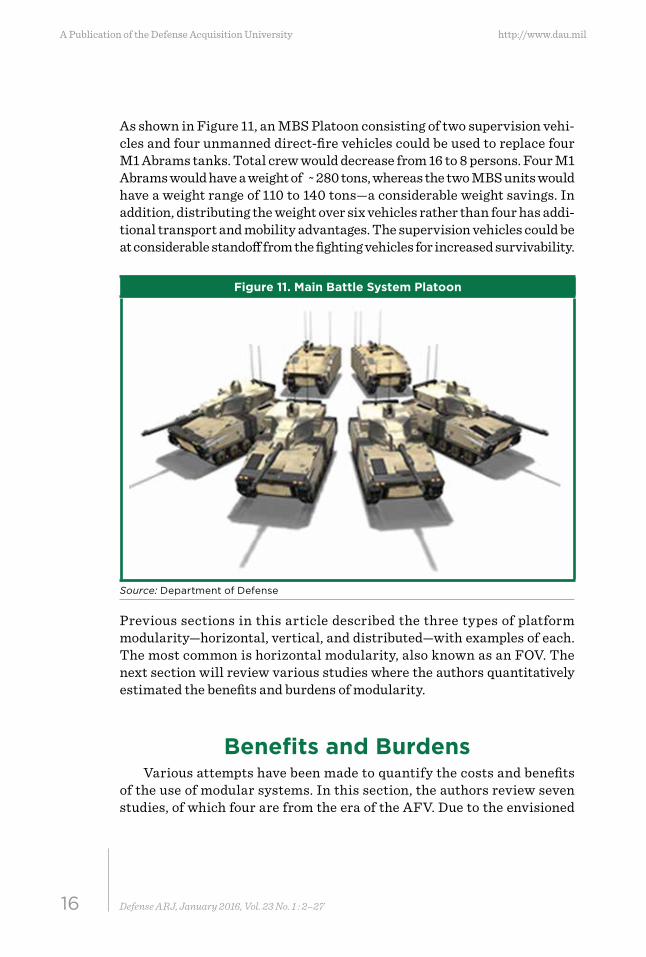
The Main Battle System (MBS) is a recent TARDEC concept that utilizes distributed modularity (Effinger & Parker, 2013; Parker & Scott, 2013). The goal is to replace a 70-ton M1A2 Abrams tank with three vehicles: a 25- to 30-ton manned vehicle with a crew of four and two 15- to 20-ton unmanned vehicles, each with a 120mm cannon. The crew of four would include a vehicle operator, a commander, and two unmanned vehicle operators. The manned crew vehicle would not need to absorb the firing load of the can-non or the weight of the ammunition. The unmanned units would not need crew-protective armor.
16 Defense ARJ, January 2016, Vol. 23 No. 1 : 2–27
A Publication of the Defense Acquisition University http://www.dau.mil
As shown in Figure 11, an MBS Platoon consisting of two supervision vehi-cles and four unmanned direct-fire vehicles could be used to replace four M1 Abrams tanks. Total crew would decrease from 16 to 8 persons. Four M1 Abrams would have a weight of ~ 280 tons, whereas the two MBS units would have a weight range of 110 to 140 tons—a considerable weight savings. In addition, distributing the weight over six vehicles rather than four has addi-tional transport and mobility advantages. The supervision vehicles could be at considerable standoff from the fighting vehicles for increased survivability.
Figure 11. Main Battle System Platoon
Source: Department of Defense
Previous sections in this article described the three types of platform modularity—horizontal, vertical, and distributed—with examples of each. The most common is horizontal modularity, also known as an FOV. The next section will review various studies where the authors quantitatively estimated the benefits and burdens of modularity.
Benefits and BurdensVarious attempts have been made to quantify the costs and benefits
of the use of modular systems. In this section, the authors review seven studies, of which four are from the era of the AFV. Due to the envisioned
17Defense ARJ, January 2016, Vol. 23 No. 1 : 2–27
January 2016
size of the AFV program, considerable effort went into evaluating costs. The final three studies are from analyses of more modern modular vehicles and concepts.
The costs/benefits of the AFV were evaluated by the Advanced Vehicle Testing Activity (AVTA) made up of Food Machinery Corporation, General Dynamics, and smaller companies. They conducted a Life Cycle Cost Analysis of the AFV (AVTA, 1988). The AVTA concluded that “the total costs shown for the Development, Production, Fielding, and Sustainment of the AFV Family of Vehicles (Heavy, Medium, and Light, Wheeled, and Trailer groups) provide a very adequate baseline for the quantification of Life Cycle Cost savings” (AVTA, 1988, p. 578). Most of the savings came from common functional packages leading to savings in development, pro-curement, training, and support costs. Average savings from the packages were in the 15–30 percent range, distributed across the entire life cycle. These are very significant savings since the O&S costs typically dwarf the research and design costs.
A second 1988 study on battle damage assessment and repair found that dam-aged vehicles could be repaired and returned to battle more quickly in the case of commonality (Kane, 1988). A final 1988 study found a negative impact from a modular AFV fleet; it compared the costs of combat service support, supply, maintenance, and transportation between an AFV fleet in theater and a conventional armored fleet upgraded to an expected 2005 configura-tion (Cunningham, Tollefson, & Malcolm, 1988). They found that the AFV fleet would be more expensive in theater, primarily because the overall fleet weight would be greater. When using a single chassis for all heavy vehicles, the chassis has to be big enough and powerful enough to support the heaviest vehicle in the class. They found the weight of all heavy tracked vehicles was 50 percent greater in the AFV case, which led to higher fuel usage and more maintenance personnel, as required, for heavier tracked vehicles.
In the study of coupled vehicles discussed earlier, a cost model known as TREAD was used to estimate production costs of a fleet of coupled tanks rel-ative to a fleet of M1 tanks (Schwartz, 1988). Certain costs would be higher such as armor due to more surface area, and sensors and communication equipment between the two units. Other costs would be lower due to the common chassis and the fact that fewer reserve units would be required. The final estimate was that in a coupled fleet with less armor on the front, an unmanned unit would cost 2–5 percent more than a tank fleet unit. If
18 Defense ARJ, January 2016, Vol. 23 No. 1 : 2–27
A Publication of the Defense Acquisition University http://www.dau.mil
both units were produced with armor comparable to the M1, costs would be 14–19 percent higher for the coupled vehicles. Other costs such as research and development (R&D) and O&S were not considered.
During FCS Phase I, SAIC evaluated the conventional unique vehicle con-cept versus a modular concept for an 18-ton platform (SAIC, 2000). Using TARDEC’s taxonomy, they determined that horizontal modularity was more efficient than vertical modularity due to poor mobility and surviv-ability characteristics of independent modules and the need for a complex and heavy mating joint. However, the horizontally modular platform was also not ideal because it required a heavier hull structure to implement; the structure would have to be heavy enough to accommodate the largest, heaviest variant, meaning that the powertrain, suspension, tracks, etc., would be overdesigned for lighter variants. In addition, the modules would require a ballistic joint that would be difficult to seal. Overall, they calcu-lated that unique hulls are 10–30 percent more weight/volume efficient than a horizontally modular platform.
19Defense ARJ, January 2016, Vol. 23 No. 1 : 2–27
January 2016
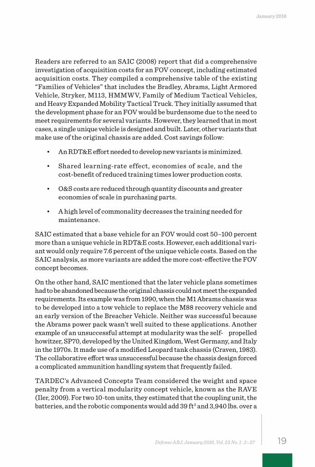
Readers are referred to an SAIC (2008) report that did a comprehensive investigation of acquisition costs for an FOV concept, including estimated acquisition costs. They compiled a comprehensive table of the existing “Families of Vehicles” that includes the Bradley, Abrams, Light Armored Vehicle, Stryker, M113, HMMWV, Family of Medium Tactical Vehicles, and Heavy Expanded Mobility Tactical Truck. They initially assumed that the development phase for an FOV would be burdensome due to the need to meet requirements for several variants. However, they learned that in most cases, a single unique vehicle is designed and built. Later, other variants that make use of the original chassis are added. Cost savings follow:
• An RDT&E effort needed to develop new variants is minimized.
• Shared learning-rate effect, economies of scale, and the cost-benefit of reduced training times lower production costs.
• O&S costs are reduced through quantity discounts and greater economies of scale in purchasing parts.
• A high level of commonality decreases the training needed for maintenance.
SAIC estimated that a base vehicle for an FOV would cost 50–100 percent more than a unique vehicle in RDT&E costs. However, each additional vari-ant would only require 7.6 percent of the unique vehicle costs. Based on the SAIC analysis, as more variants are added the more cost-effective the FOV concept becomes.
On the other hand, SAIC mentioned that the later vehicle plans sometimes had to be abandoned because the original chassis could not meet the expanded requirements. Its example was from 1990, when the M1 Abrams chassis was to be developed into a tow vehicle to replace the M88 recovery vehicle and an early version of the Breacher Vehicle. Neither was successful because the Abrams power pack wasn’t well suited to these applications. Another example of an unsuccessful attempt at modularity was the self- propelled howitzer, SP70, developed by the United Kingdom, West Germany, and Italy in the 1970s. It made use of a modified Leopard tank chassis (Craven, 1983). The collaborative effort was unsuccessful because the chassis design forced a complicated ammunition handling system that frequently failed.
TARDEC’s Advanced Concepts Team considered the weight and space penalty from a vertical modularity concept vehicle, known as the RAVE (Iler, 2009). For two 10-ton units, they estimated that the coupling unit, the batteries, and the robotic components would add 39 ft3 and 3,940 lbs. over a
20 Defense ARJ, January 2016, Vol. 23 No. 1 : 2–27
A Publication of the Defense Acquisition University http://www.dau.mil
unique vehicle—an increase of about 10 percent in weight. In addition, two structural walls were needed at the connection point, whereas one or none are needed in a unique vehicle.
Table 1 summarizes the studies described in this section. Some studies were evaluating only one facet of modularity such as repair costs. Overall, three studies found a net benefit, three found a net burden, and one found it could go either way depending on the assumptions. So many variables are affected by modularity during the different phases of design, engineering, production, usage, repair, and sustainment that a definitive answer will depend on circumstances.
TABLE 1. VARIOUS MODULARITY STUDIES AND DECISION AS TO BENEFIT OR BURDEN
Vehicle Group Reference Benefit or Burden
Comments
AFV AVTA Benefit 15–30% savings in development, procurement, support
AFV repair Kane Benefit Due to commonality
AFV Cost in Theater
Cunningham, Tollefson, & Malcolm
Burden Higher fleet weight due to common chassis
Coupled Vehicles Schwartz Benefit or Burden
Depends on whether front vehicle is fully armored
FCS Phase I SAIC Burden Overdesign; parasitic hull weight
Families of Vehicles
SAIC Benefit Reduced costs in design, commonality, economies of scale
RAVE weight analysis
TARDEC Burden 10% increase in weight
Summary and DiscussionBased on the taxonomy developed by TARDEC’s Advanced Concepts
Team, three types of modularity were considered: horizontal, vertical, and distributed. By far, the most common today is horizontal, also described as an FOV, in which a common chassis and powertrain are used for a number of variants. An important aspect of structural modularity is the ease of changing from one vehicle variant to another. Can it be done in the field,
21Defense ARJ, January 2016, Vol. 23 No. 1 : 2–27
January 2016
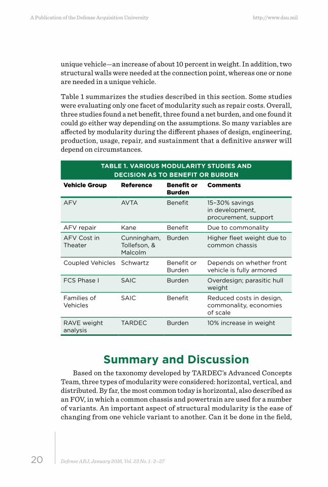
or at a depot, or only in a production facility? In the vast majority of cases, these variants are purchased as is from the manufacturer and are not inter-changeable in the field. A summary of the advantages and disadvantages of each type of modularity is captured in Table 2.
TABLE 2. ADVANTAGES AND DISADVANTAGES OF VARIOUS FORMS OF MODULARITY
Type of Modularity Advantages DisadvantagesHorizontal Modularity
• Reduced design for later vehicles
• Commonality is built in
• Designing entire family from scratch may be impossible
• Variants usually from production facility
• Must be overdesigned to accommodate largest variant
Vertical Modularity • Decreased weight of each module
• More transportable• Reconfigurable in field• Unmanned modules
need less protection• Articulated has greater
mobility
• Overall weight greater• Some parts must be
duplicated in each module
Distributed Modularity
• Decreased weight of each module
• More transportable• Reconfigurable in field• Most flexible of all
systems• Unmanned modules
need less protection
• Overall weight greater• Greatest need for semi-
autonomous modules• Some parts must be
duplicated in each module
• Need good communications networks
• Greatest complexity
From the previous discussion, there are obviously some advantages and disadvantages to modular vehicles. Held et al. (2008, p. 3) determined that “nuanced decision making is required” to gain a significant benefit from commonality. The same can be said of modularity. Some points to consider are captured in the following discussion:
Design Considerations• For any modular vehicle, design and RDT&E considerations
will be more extensive than for a unique vehicle.
22 Defense ARJ, January 2016, Vol. 23 No. 1 : 2–27
A Publication of the Defense Acquisition University http://www.dau.mil
• If the chassis for a unique vehicle is used later for additional vehicles, design and R&D requirements will be less for suc-ceeding variants. Conversely, the original chassis might not support requirements of succeeding variants.
• Attempts to design an entire FOV can easily become over-whelmed by competing requirements for the variants.
Weight• In many forms of modularity, the total weight of the modular
vehicle will be greater than that of a unique vehicle, due to overdesign for some variants, parasitic structure, and possible extra sensors, powertrains, communication devices, etc., if the modules are capable of independent mobility.
• In the case of vertical or distributed modularity, the individ-ual modules each weigh less than the total vehicle, which has benefits for transport and mobility.
23Defense ARJ, January 2016, Vol. 23 No. 1 : 2–27
January 2016
• In the FOV example, the chassis will need to be heavy and powerful enough to support all variants. This overdesign requirement would increase vehicle size/weight for some variants.
Adaptability• Since the vast majority of today’s horizontally modular/
common chassis vehicles are factory-produced, no gain in operational adaptability occurs.
• Vehicle variants that can be interchanged in the field are excep-tional today. However, two recent examples were provided: the German-Dutch Boxer and the United Kingdom Cameleon, which can be rapidly changed from one variant to another.
Costs/Benefits• The use of the modular approach in vehicles is a potential solu-
tion to address combat developer and program requirements for supportability, cost, and adaptable and flexible vehicles.
• The modular approach comes at a price in trade-offs, which must be considered when applying it to a vehicle development effort.
Path ForwardModularity undoubtedly has strong potential benefits in lowered costs
and a more adaptable force. However, the survey of successful and failed modularity attempts does not present a clear picture to assess the benefits of modularity. As quoted in a recent study, “the effect of modularity on the entire fleet must be considered with a careful analysis of both performance and life-cycle cost implications” (Bayrak et al., 2015, p. 2). Two studies have recently been initiated to delve deeper into these issues.
TARDEC has initiated a study through the ARC to establish a modeling framework for assessing the adaptability and costs of a modular military vehicle fleet (Bayrak et al, 2015). Their efforts center on model simulations of powertrain demands, fleet operations, transportation costs, operating costs, and acquisition costs, with a comparison of a modular fleet versus a conventional fleet. Unlike earlier examples, the design of the individual modular vehicle is not being considered. Rather, its modeling framework includes the following items:
24 Defense ARJ, January 2016, Vol. 23 No. 1 : 2–27
A Publication of the Defense Acquisition University http://www.dau.mil
• Function Selection and Attributes
• Conventional and Modular Fleet Models
• Mobility and Fuel: Powertrain Models
• Fleet Operation Models
• Cost Models
° Transportation
° Acquisition Considering Manufacturing
° Fleet Operation
Building on the ARC effort, the ONR announced a Vehicle Agnostic Modularity Project Plan (VAM, 2014, p. 28), with a goal of understand-ing and demonstrating modular vehicles. The hypothesis of VAM is that a well-structured application of modularity will “extend tactical range, extend operational reach and increase endurance in the field, reduce excess capacity and reduce logistic footprint/burden, enhance small unit effectiveness, lighten the Marine Air-Ground Task Force load, enhance commonality, and reduce Total Owner Cost” (VAM, 2014, p. 41). Over the course of several years, VAM will explore the benefits of vehicle modularity as well as its challenges.
An underlying premise of these studies is that a unique vehicle geared to a specific mission will always outperform a modular vehicle. However, over a set of varied missions over a longer timeframe, the modular fleet may offer cost and agility benefits compared to a conventional fleet. These efforts by ONR and TARDEC are providing decision makers a framework to determine the value of modular fleets in operational environments.
25Defense ARJ, January 2016, Vol. 23 No. 1 : 2–27
January 2016
ReferencesAckerman, S. (2011, July). Next Army chief isn’t so cool with a smaller force. Wired.
Retrieved from http://www.wired.com/2011/07/next-army-chief-isnt-so-cool-with-a-smaller-force
Ajlouny, J., Atkinson, R. V., Barragato, A. R., Boismier, J. D., & Bolon, M. D. (1988). Armored family of vehicles concept design study (Vol. 1). DTIC Accession No. ADB121266. Warren, MI: U.S. Army Tank Automotive Research, Development and Engineering Center.
army-technology.com. (n.d.). Patria AMV armoured modular vehicle, Finland. Retrieved from http://www.army-technology.com/projects/patria/
army-technology.com. (n.d.). Stryker armoured combat vehicle family, United States of America. Retrieved from http://www.army-technology.com/projects/stryker
ASM Program. (2013, October). In Wikipedia [Online encyclopedia]. Retrieved from https://en.wikipedia.org/wiki/ASM_Program
Bayrak, E., Egilmez, M., Kuang, H., Li, X., Park, J. M., Papalambros, P., … Anderson, E. (2015, August). MARVEL—A modular vehicle fleet simulation tool. Paper presented at the NDIA Ground Vehicle Systems Engineering and Technology Symposium, Novi, MI.
Beck, R. R., & Kamm, I. O. (1974). Cybernetically coupled research vehicle: An interim report (Technical Report 11870). Warren, MI: U.S. Army Tank-Automotive and Armaments Command.
Beck, R. R., & Kamm, I. O. (1975). Cybernetically coupled M113 APC’s. Paper presented at 5th International Conference, International Society for Terrain-Vehicle Systems, Vol. III, Detroit, MI, June 1975, pp. 857–901.
Boelke, R. D. (1992). A historical summary of the armored systems modernization program and the lessons learned from its interactions with the acquisition environment [Master’s thesis]. Retrieved from http://calhoun.nps.edu/handle/10945/30593
Boxer. (2015). In Wikipedia [Online encyclopedia]. Retrieved from https://en.wikipedia.org/wiki/Boxer_(armoured_fighting_vehicle)
Craven, R. C. F. (1983, May-June). A 70 for the 90s. Field Artillery Journal, 51(3), 26–31.Cunningham, A., Tollefson, E., & Malcolm, M. (1988). Armored family of vehicles (AFV)
supportability sub-analysis (DTIC Accession Number SV 26777). Fort Eustis, VA: Armored Family of Vehicles Task Force.
Dasch, J. M. & Gorsich, D. J. (2012). The TARDEC story, sixty-five years of innovation. Warren, MI: U.S. Army Tank Automotive Research, Development and Engineering Center.
Effinger, C. & Parker, J. (2013, March). Main battle system (MBS) concept [TARDEC White Paper]. Warren, MI: U.S. Army Tank Automotive Research, Development and Engineering Center.
General Accounting Office. (1991). Armored systems modernization: Program inconsistent with current threat and budgetary constraints (Report No. GAO/NSIAD-91-254). Washington, DC: Author.
Government Accountability Office. (2009). Defense acquisitions: Key considerations for planning future Army combat systems (Report No. GAO-09-410T). Washington, DC: Author.
Held, T., Newsome, B., & Lewis, M. W. (2008). Commonality in military equipment (Report No. RAND_MG719). Santa Monica, CA: RAND Arroyo Center.
26 Defense ARJ, January 2016, Vol. 23 No. 1 : 2–27
A Publication of the Defense Acquisition University http://www.dau.mil
Holland, J. P. (2013). Engineered Resilient Systems (ERS) overview [Powerpoint slides]. Retrieved from http://www.defenseinnovationmarketplace.mil/resources/ERS_Overview_2DEC2013-Final.pdf
Hunnicutt, R. P. (1990). A history of the American main battle tank. Novato, CA: Presidio Press.
Iler, C. (2009). Modular vehicle concept studies. Briefing to DARPA Tactical Technology Office, Washington, DC.
Kane, J. J. (1988, January). The impact of commonality on battle damage assessment and repair in the armored family of vehicles. Proceedings of the IEEE Annual Reliability and Maintainability Symposium, Los Angeles, CA. doi: 10.1109/ARMS.1988.196418
Kotchman, D. P. (2004, January-February). Manned ground vehicles—Redefining system development. Army AL&T, 44–49.
Lopez, R. L. (1987). The US Armoured family of vehicles (DTIC Accession No. WSTIAC-PA-54111). International Defense Review, 53–55.
OVIK Cameleon IV440 Modular Mission Vehicle. (2015). In Wikipedia [Online encyclopedia]. Retrieved from https://en.wikipedia.org/wiki/OVIK_Cameleon_IV440_Modular_Mission_Vehicle
OVIK Crossway. (n.d.). World class armoured vehicle manufacturers. Retrieved from http://www.ovik-crossway.com/ovik-vehicle9.php
Parker, J., & Scott, J. (2013, March). Main battle system (MBS) operational scenarios [TARDEC White Paper]. Warren, MI: U.S. Army Tank Automotive Research, Development and Engineering Center.
Patria AMV. (2015). In Wikipedia [Online encyclopedia]. Retrieved from https://en.wikipedia.org/wiki/Patria_AMV
Pernin, C. G., Axelband, E., Drezner, J. A., Dille, B. B., Gordon, J. IV, Held, B. J., … Sollinger, J. M. (2012). Lessons from the Army’s Future Combat Systems program. Santa Monica, CA: RAND Arroyo Center.
Schwartz, R. E. (1988). Coupled vehicle tanks and the armored family of vehicles (DTIC Accession No. AD-B122 923). Alexandria, VA: Institute for Defense Analyses.
Science Applications International Corporation. (2000). Modularity study. Unpublished manuscript, Tysons Corner, VA.
Science Applications International Corporation (2008, July). Acquisition cost estimating relationships for a family of vehicles (Delivery Order 9, Task 2a DASW01-02-A-0022). Tysons Corner, VA: Wheeled and Tracked Vehicle Support.
Stryker. (2015). In Wikipedia [Online encyclopedia]. Retrieved from https://en.wikipedia.org/wiki/Stryker
Sunell, R. J., Logan, J. A., Inman, S. E., Greene, L. F., Gibson, J. W., Hallissey, S. C., ... Williamson, E. W. Jr. (1987). Armored family of vehicles (AFV) phase 1 report. Fort Eustis, VA: Armored family of vehicles (AFV) phase 1 report. Fort Eustis, VA: Armored Family of Vehicles Task Force.
Taylor, G. (1992, September-October). TARDEC gets robot vehicle control system.Army Research, Development & Acquisition Bulletin. Alexandria, VA: U.S. ArmyMateriel Command.Vehicle Agnostic Modularity (VAM). (2014). Program executive officer land systems
advanced technology investment plan (Vol. V). Arlington, VA: Office of Naval Research Science and Technology.
27Defense ARJ, January 2016, Vol. 23 No. 1 : 2–27
January 2016
Wynbelt, W. P. (1972). Twister vs tracks: A comparative evaluation (Technical Report No. WSTIAC-PA42061). Warren, MI: U.S. Army Tank-Automotive and Armaments Command.
Zanini, D. (2009). MGV preliminary design review. Warren, MI: PM Future Combat Systems (Brigade Combat Team).
BiographiesDr. Jean M. Dasch is a principal scientist with Alion Science and Technology and works at the U.S. Army Tank Automotive Research, Development and Engineering Center (TARDEC), Office of the Chief Scientist. Formerly, she was a Technical Fellow at General Motors Research & Development Center where she conducted research on environmental issues with vehicles and manufacturing plants. Dr. Dasch holds a PhD from the University of Maryland in Nuclear and Atmospheric Chemistry.
(E-mail address: [email protected])
Dr. David J. Gorsich serves as TARDEC’s Chief Scientist as well as the Army’s Senior Research Scientist (ST) for Ground Systems. He has a technical specialization in modeling and simu-lation. His current research interests are vehicle dynamics and structural analysis, vehicle design/optimization, reliability, underbody blast analy-sis, and terrain modeling. Dr. Gorsich is a Fellow with the Society of Automotive Engineers and holds a PhD from the Massachusetts Institute of Technology in Applied Mathematics.
(E-mail address: [email protected])