Survey Guidelines for Tankers
164
GD26-2013 CHINA CLASSIFICATION SOCIETY SURVEY GUIDELINES FOR OIL TANKERS IN SERVICE 2014 Implementation date: July 1, 2014
-
Upload
reetam-bose -
Category
Documents
-
view
15 -
download
0
description
Survey Guidelines for Tankers
Transcript of Survey Guidelines for Tankers

7/21/2019 Survey Guidelines for Tankers
http://slidepdf.com/reader/full/survey-guidelines-for-tankers 1/164
GD26-2013
CHINA CLASSIFICATION SOCIETY
SURVEY GUIDELINES FOR OIL
TANKERS IN SERVICE
2014
Implementation date: July 1, 2014

7/21/2019 Survey Guidelines for Tankers
http://slidepdf.com/reader/full/survey-guidelines-for-tankers 2/164
Survey Guidelines for Oil Tankers in Service
Catalogue
Preamble ............................................................................................................................................ ‐ 1 ‐
Chapter 1, General ............................................................................................................................. ‐ 2 ‐
Section 1 Type of Oil Tanker ........................................................................................................... ‐ 2 ‐
Section 2 Additional Requirement of Oil Tanker ............................................................................ ‐ 4 ‐
Section 3 Typical ARRANGEMENTS and Structural Type of Oil Tanker .......................................... ‐ 5 ‐
Chapter 2, Safety of Survey and Inspection ..................................................................................... ‐ 10 ‐
Section 1 General Information ..................................................................................................... ‐ 10 ‐
Section 2 Survey Preparations and Means of Access ................................................................... ‐ 15 ‐
Chapter 3, Surveys and Services Provided by Class on Oil Tanker ................................................... ‐ 17 ‐
Section 1 Definitions about Surveys to Oil Tanker ....................................................................... ‐ 17 ‐
Section 2 Class Characters and Notations .................................................................................... ‐ 18 ‐
Section 3 Preparations to Survey Questionnaire ......................................................................... ‐ 19 ‐
Section 4 Preparation of Survey Programme ............................................................................... ‐ 20 ‐
Section 5 Brief INSTRUCTIONS to Class Survey After Construction ............................................. ‐ 21 ‐
Section 6 Statutory Surveys .......................................................................................................... ‐ 26 ‐
Section 7 CAP Survey .................................................................................................................... ‐ 27 ‐
Chapter 4, Inspections to Structures of Oil Tanker .......................................................................... ‐ 28 ‐
Section 1 Inspection
to
Hull
Structure
..........................................................................................
‐28
‐
Section 2 Coating Protection ........................................................................................................ ‐ 43 ‐
Section 3 Safe Access of Oil Tankers ............................................................................................ ‐ 47 ‐
Section 4 Repairs of Hull ............................................................................................................... ‐ 51 ‐
Chapter 5, Fire Protection, Fire Detection and Fire Extinction ........................................................ ‐ 62 ‐
Section 1 Fire Structural Protection ............................................................................................. ‐ 62 ‐
Section 2 Fire Extinction SYSTEMS ............................................................................................... ‐ 65 ‐
Section
3
Venting
System
............................................................................................................. ‐
67 ‐
Section 4 Additional Requirements for Cargo Area ..................................................................... ‐ 68 ‐
Section 5 Additional Requirements of Cargo Pump Room .......................................................... ‐ 82 ‐
Section 6 Inert Gas System ........................................................................................................... ‐ 82 ‐
Section 7 Fire‐fighting Appliances ................................................................................................ ‐ 85 ‐
Section 8 Maintenance of Fire‐Fighting Equipment ..................................................................... ‐ 85 ‐
Section 9 Equivalence of Design and Arrangements of the Fire‐Fighting Equipment ................. ‐ 86 ‐
Chapter 6, Pollution Prevention of Oil Tanker ................................................................................. ‐ 87 ‐
Section 1 Crude Oil Washing System ............................................................................................ ‐ 87 ‐

7/21/2019 Survey Guidelines for Tankers
http://slidepdf.com/reader/full/survey-guidelines-for-tankers 3/164
Survey Guidelines for Oil Tankers in Service
Section 2 Oil Discharge Monitoring and Control System ............................................................. ‐ 88 ‐
Section 3 Oil/Water Interface Detector ....................................................................................... ‐ 90 ‐
Section 4 Oily Water Discharge Control ....................................................................................... ‐ 91 ‐
Section 5 Vapor Emission Control System .................................................................................... ‐ 92 ‐
Chapter 7, Additional Requirements Related to Oil Tankers ........................................................... ‐ 94 ‐
Section 1 Steering Gear System ................................................................................................... ‐ 94 ‐
Section 2 Emergency Towing Arrangements ................................................................................ ‐ 95 ‐
Section 3 Watch Windows in Ballast Tank ................................................................................... ‐ 96 ‐
Section 4 Life‐Saving Appliances for Oil Tankers .......................................................................... ‐ 96 ‐
Section 5 Others ........................................................................................................................... ‐ 97 ‐
Chapter 8, Brief Introduction of the Inspection Raised by OilCompanies ....................................... ‐ 98 ‐
Appendix ........................................................................................................................................... ‐ 99 ‐
Annex 1 Minimum REQUIREMENT of the Internal Examinations to all the tanks of self ‐propelled
integrated Oil Tankers .................................................................................................................. ‐ 99 ‐
Appendix 2: Inspections to Critical Structural Areas .................................................................. ‐ 106 ‐
Appendix 3 Typical Structure Details Failures and Recommended Repairs ............................... ‐ 115 ‐
Annex 4 Appendix I of MARPOL Annex I .................................................................................... ‐ 160 ‐

7/21/2019 Survey Guidelines for Tankers
http://slidepdf.com/reader/full/survey-guidelines-for-tankers 4/164
Survey Guidelines for Oil Tankers in Service
- 1 -
PREAMBLE
Oil Tanker is attributed to the high-risk vessel for the flammability and explosibility features of thecargoes carrying on it. Once the oil spill occurs on an Oil Tanker, the ocean circumstance will encounter a
serious pollution, especially as the oil tankers have become larger and larger, the oil spill after damage ofoil tanker might lead to a great hazard to the ocean and the adjacent coastlands. Therefore, International
Maritime Organization (IMO), Flag States, Port States, Members of International Association ofClassification Societies (IACS), Organizations of Oil Companies, etc. have to place the Safety of Oil
Tankers on a very important position, and provide more and more requirements through Conventions,Regulations, Uniform Requirements of IACS, Various Rules of classification societies, Inspection
Questionnaires of Oil Companies, etc. to request strictly inspections to Oil tanker with high safetystandards.
As an important component of Maritime Risk Management System, Surveys on ships are well controlled by China Classification Society (CCS) to ensure safety shipping and clean ocean. Having been aware of
that finding out risk elements during surveys are always depending on judgments or experiences ofsurveyor himself, CCS makes a lot of efforts to improve the ability of surveyors by adequate training,
sharing the experiences of the whole organization, periodical review of rules, and in-time efficienttechnical supporting, etc. Realizing the developing direction of larger Oil Tankers, CCS investigated the
structural features of oil tankers and compiled this Book of Survey Guidelines.This book combines in one document the various sources of information from IMO, IACS or
Organizations of Oil Companies, necessary for directing how to conduct surveys or inspections on oiltankers, and incorporates with the experiences and practices of CCS.
In this book, guidance is given firstly on survey preparation, including a review of requirements, safetyaspects, equipment, and details of carrying out and reporting different types of surveys. The analysis ofstructure failure data follows with the interpretation of wastage and structural defects in terms of the
effects on local strength or overall structural integrity. Basic maintenance and repair guidelines are
provided along with sketches of experienced structural failures and proposed repairs. The book alsoincorporates the experiences of IACS and CCS about inspection and maintenance of oil tanker equipment.The guidelines in this book are only applicable to self-propelled classed oil tankers in worldwide service,
with integrated cargo tanks, and with the additional class notation of ESP.
The guidelines in this book are incorporated based upon relevant IMO Conventions, IACS uniformrequirements and the Rules of CCS, which are in force prior to the September of 2013. Any amendmentsto these documents are to be noted when using the guidelines of this book to instruct inspection or
maintenance to oil tankers.

7/21/2019 Survey Guidelines for Tankers
http://slidepdf.com/reader/full/survey-guidelines-for-tankers 5/164
Survey Guidelines for Oil Tankers in Service
- 2 -
CHAPTER 1, GENERAL
SECTION 1 TYPE OF OIL TANKER
Oil tanker means a ship constructed or adapted primarily to carry oil in bulk in its cargo spaces, oil means
petroleum in any form including crude oil, fuel oil, sludge, oil refuse and refined products (other than
those petrochemicals), the specific name of the oil refer to the Appendix to the Annex of MARPOL 73/78.According to the requirements of MARPOL 73/78 Annex I, oil tanker means a ship primarily to carry oilin bulk in its cargo spaces and includes combination carries, any “NLS tanker” as defined in Annex II of
the present Convention and any gas carrier as defined in SOLAS 74 (as amended) Reg. II-1/3.20, whencarrying a cargo or part cargo of oil in bulk.
According to the above definition, the oil tanker can be subdivided into:
Crude Oil Tanker
Crude Oil/Product Carrier
Product Carrier
Combination Carrier
Chemical Tanker/Product Carrier
Liquefied Gas/Product Carrier
1. Typical Arrangement and Feature of Crude Oil Tanker
Crude oil tanker means an oil tanker engaged in the trade of carrying crude oil, the deadweight of which is
generally from 20,000 to 60,000 tonnes. The oil tanker can be divided into five categories based on DWT by world shipbuilding and ship industry:
(1) Panamax: The type of ship is terms for the size limits for ships traveling through the Panama Canal(such as the allowable size is limited by the width and length by the Canal), which are with displacement
between 50,000 and 80,000 DWT.(2) Aframax: The type of ship is the Average Freight Index(AFRA) highest ship, which have the best
economic and was the optimum tanker which suitable for the Baltic Sea ice class sailing. This type ofships is with displacement between 80,000 and 120,000 DWT.
(3) Suezmax: The type of ship is terms for the size limits for ships traveling through the Suez Canal, whichare with displacement between 120,000 and 200,000 DWT.
(4) VLCC: The very large crude oil carrier which are with displacement between 200,000 and 320,000DWT.
(5) ULCC: The ultra large crude oil carrier which are with displacement over 320,000 DWT.The crude oil tanker generally equipped with Crude Oil Washing system (COW), Inert Gas System (IGS),
Oil Discharge Monitoring system (ODME), Deck Foam system and etc. Currently, the VAPOUR recoverysystem is required to installed on oil tanker in some port or oil terminals (such as U.S. port), theappropriate technical requirements has been given in CCS rules.
The crude oil tankers currently have single-hull and double-hull types in the aspect of structure, single-hull
oil tanker is required to converse to double-hull in accordance with the requirements of MARPOL Annex I,the specific time refer to section 3.2 of this Chapter. The crude oil tanks also have middle cross tie and sidecross tie types in the aspect of different cross tie installation. Due to some crude oil tankers loading high
sulfur content products, and at the request by ship’s owner, an additional corrosion protective coating was
painted on the deck side and/or lower part and floor in cargo tank for more protecting the internal structureof cargo tank.
2. Typical Arrangement and Feature of Product Carrier
Product carrier means an oil tanker engaged in the trade of carrying oil other than crude oil and which arewith displacement less than tens of thousands DWT. Product carriers have more than one longitudinal bulkheads and few additional internal corrosion protective coating in the cargo tank in aspect of structure.
3. Typical Arrangement and Feature of Crude Oil/Product Carrier
Crude oil/product oil combination carrier means the tanker which has the crude oil carrier characteristics,the system is equipped both to meet the requirements of crude oil carrier and the requirements of other oil
products in accordance with MAROPL Annex I.
4. Typical Arrangement and Feature of Combination Carrier
7/21/2019 Survey Guidelines for Tankers
http://slidepdf.com/reader/full/survey-guidelines-for-tankers 6/164
Survey Guidelines for Oil Tankers in Service
- 3 -
Combination carrier means a ship designed to carry either oil or solid cargoes in bulk, which normally
includes Ore/Oil carrier and Ore/Bulk/Oil carrier, the system is equipped to meet the requirements of oilcarried in bulk. The combination carrier has the characteristics of bulk carrier in aspect of structure that
has topside tank, hopper tank and single deck structure, usually with longitudinal bulkheads around thecargo area and coating protection in the cargo tanks.
5.
Typical arrangement and feature of Chemical Tanker/Product Carrier
Chemical tanker/product carrier is the ship used for the carriage in bulk of chemical and oil, the cargomaintenance system can meet the requirement of carrying oil in bulk. The structure is similar with that ofoil tanker, in general, a certain cargo tank is designated as a slop tank and dedicated cargo oil slop tank is
unnecessary to be equipped.
6. Typical Arrangement and Feature of Liquefied Gas/Product Carrier
Liquefied gas/product carrier is the ship used for the carriage in bulk of any liquefied gas and oil, the cargo
maintenance system can meet the requirements of carrying oil in bulk. The structure is similar with that of
oil tanker; in general, a certain cargo tank is designated as a slop tank.

7/21/2019 Survey Guidelines for Tankers
http://slidepdf.com/reader/full/survey-guidelines-for-tankers 7/164
Survey Guidelines for Oil Tankers in Service
- 4 -
SECTION 2 ADDITIONAL REQUIREMENT OF OIL TANKER
Compared with bulk carrier, survey to oil tanker has its particularities which including:(1) Structural safety of oil tankers, including oil tanker structural details, arrangement and compartment of
cargo tank and mariner spaces, cargo tanks of double-hull protection, arrangement of pump rooms, safety
access to tanker bows, safety access to cargo oil area and its vicinity area, arrangement of permanentmeans of access (PMA) and the requirement of oil tanker cargo area sea water ballast tank coating whichrequired by CSR of Tanker, etc.
(2) Pollution prevention requirements of the cargo area of oil tankers (including crude oil washing system(COW), oil discharge monitoring system (ODME), oil water interface detector and bilge water/oil residue
discharge control, vapor recovery system (VCS/VCT-S), etc.)(3) Fire protection and fire-fighting safety requirements, including fire-resisting divisions and openings of
accommodation bulkheads which facing cargo oil area, arrangement of fire-fighting equipments (fixeddeck foam system in cargo area, water spray system, IGS), the protection of fire and explosion of pumproom, emergency towing arrangements, etc.
(4) Technical requirement of cargo maintenance, including fixed tank gauging and alarm system,
arrangement of venting system, etc.
(5) Protection of explosion of oil tankers, including hazardous area classification and arrangement offlammable gas detector, etc.
(6) Arrangement and requirement of steering gears.
(7) Arrangement and requirement of life-saving equipment.(8) The requirement of OCIMF and oil companies.The above mentioned will be described in details in the following sections.

7/21/2019 Survey Guidelines for Tankers
http://slidepdf.com/reader/full/survey-guidelines-for-tankers 8/164
Survey Guidelines for Oil Tankers in Service
- 5 -
SECTION 3 TYPICAL ARRANGEMENTS AND STRUCTURAL TYPE OF OIL
TANKER
According to the structural type, oil tanker can be divided into single-hull oil tanker, double-hull oil tankerand the oil tanker with independent tanks. Since the oil tanker with independent tanks, such as asphalt ship,
chemical/product carrier and combination ship and liquefied gas carrier/oil tanker combination ship havenot been involved enhanced survey plan, it is unnecessary to meet the requirements of IACS URZ10.1 andURZ10.4 which are not included in this guidelines.
1. Typical Arrangement of Oil Tanker
Oil tankers are normally stern-engined ships, according to the requirements of SOLAS, bridge wings on
both sides of the tankers which keel laid on or after 1 July 1998 are to extend to both port and starboard
sides, from each bridge wing the horizontal field of vision is to extend over an arc of at least 225°, both
sides are to be visible from the bridge wing. And according to the requirements of oil companies, bridge
wing is to extend to ship sides, where it is difficult to arrange, at least the discharging tanker while in STSoperation is to be so arranged that the bow deck is to be raised slightly or forecastle is to be fitted. . For
the oil tankers with the flash point ≤60℃it is to be forbidden to fit the forecastle on the cargo tanks,
arrange the entrance for the forecastle in front of the gas hazardous area, and arrange bridge higher thanmain deck at the middle part of the oil tanker. The cargo area was isolated from machinery space by cargo
pump rooms, oil fuel bunker tanks or cofferdams, etc. The ballast piping, bilge piping, ventilation piping,
piping of cargo handling and maintenance system in cargo areas are to be fully independent / isolated frommachinery space. The pumps in cargo areas may be locally controlled in the cargo pump rooms, whichdriven by shaft of generator or ejector in machinery space through pump room bulkheads where the shaft
seal is to be fitted. The cargo pump was driven by saturated steam on some part of oil tankers, the
bulkhead between machinery space and cargo pump room may not fit the shaft seal where the this kind ofdrive system arranged in cargo pump rooms.
Generally, the cargo area and ballast tanks in bow are isolated by cofferdams. Where the cofferdam is notfitted between fore peak and cargo area, such fore peak area is to be capable of entrancing from gas safetyzone on the weather deck directly.
2. Double Hull Oil Tanker
The oil tankers1 of 5,000 tonnes deadweight and above delivered on or after 6 July 1996 are to comply
with the requirements of double structure (double hull and double bottom), double structure is to comply
with the requirements of CCS rules and MARPOL Annex I, the detail requirements are as follows:Oil tanker of 5,000 tonnes deadweight and above:
(1) The breadth of wing tanks or spaces: w = 0.5 + DW/20,000 (m), or w = 2.0 m, whichever is the lesser.The minimum value of w = 1.0 m.
(2) The height of double bottom tanks or spaces: h = B/15 (m) or h = 2.0 m, whichever is the lesser. The
minimum value of h = 1.0 m.Oil tanker of less than 5,000 tonnes deadweight:

7/21/2019 Survey Guidelines for Tankers
http://slidepdf.com/reader/full/survey-guidelines-for-tankers 9/164
Survey Guidelines for Oil Tankers in Service
- 6 -
(1) The wing tanks and double bottom tanks may be fitted as the requirements of oil tanker of 5,000 tonnes
deadweight and above, or(2) At least be fitted with double bottom tanks or spaces having such a depth that: h = B/15 (m), with a
minimum value of h = 0.76 m, and(3) be provided with cargo tanks so arranged that the capacity of each cargo tank does not exceed 700 m3
unless wing tanks or spaces are arranged: w = 0.4 + 2.4 DW / 20,000 (m) with a minimum value of w =
0.76 m.It is to be noted that, for oil tankers of 20,000 tonnes deadweight and above delivered on or after 6 July1996, the damage assumptions are to be supplemented by the following assumed bottom raking damage:Longitudinal extent:
(1) Ships of 75,000 tonnes deadweight and above: 0.6L measured from the forward perpendicular;
(2) Ships of less than 75,000 tonnes deadweight: 0.4L measured from the forward perpendicular;Transverse extent: B/3 anywhere in the bottom;Vertical extent: breach of the outer hull.
It is to be noted that in accordance with IACS URZ10.4, if the oil tanker actually fitted with double hull,
but which does not comply with the above spacing requirement, that the oil tanker may be surveyed as adouble hull oil tanker and been assigned with “Single Hull” class notation, meanwhile, the relevant classmemorandum has been given in Survey Status of CCS Ship Service Information Management System.
Some part of the oil tanker which delivered on or before 6 July 1996, as defined in Reg. 1.28.5 ofMARPOL Annex I met the requirement of double structure oil tanker while in new construction; for theoil tanker of 5,000 deadweight or above which do not comply with this requirements (including the oiltanker which double structure spacing do not comply with this requirements
3), except for which the
following ships are to be phased-out or conversion according to the following schedule, the oil tanker of
the rest have already been phased-out or conversed to double-hull oil tankers which comply with theapplicable requirements of in Reg. 19 and 28.6 (other than the oil tankers only navigating in the domesticsea waters in that country with the special consent by the Administration):
(1) Oil tankers complying with the new-built oil tankers requirements defined in 1.28.4 of MARPOL
Annex I;(2) Oil tankers of 20,000 DWT carrying crude oil, fuel oil, heavy diesel oil or lubricating oil as cargoesor oil tankers less than 30,000 DWT carrying oils other than the above-mentioned, not complying with the
new-built oil tankers requirements defined in 1.28.4 of MARPOL Annex I.The phase-out and conversion schedule for the oil tankers mentioned in (1) and (2) are as followings:Date required for meeting the double-hull requirements
Oil tankers of 5,000 DWT orabove
the anniversary date of delivery in 2009 for the oil tankers delivered in 1983the anniversary date of delivery in 2010 for the oil tankers delivered in 1984 or later
Despite of the above-mentioned provisions, the Administration may allow the oil tankers of 5,000DWT or
above delivered on 1st June 1982 or later4 to operate till the 25th anniversary other than double-hull
conversion, provided that:1) The oil tanker only fitted with the double- bottom or double-side or double-hull which not carryingoils and extending to the whole length of cargo tank, it is to be noted that such arrangement is to be
verified and consented by the Administration.
2) The oil tankers were still under operating conditions till 1st July 2001.3) The oil tankers are in normal order.
In addition to, the oil tankers of 5,000DWT carrying heavy oils5 and above are to comply with thedouble-hull requirements (such double-hull is to fully meet the requirements of Reg. 18 of MARPOLAnnex I). The oil tankers of 600~5,000DWT carrying heavy oils are to meet the requirements of Reg.
19.3.1 and 19.6.3 of MARPOL Annex I at the anniversary of delivery date in 2008 (i.e. not fully meetingthe double hull requirements in MARPOL), except those only operating in domestic sea waters of the
country with the special consent by the Administration.The typical structural arrangement of double-hull oil tankers are longitudinal frames for double bottom,
double side, single deck structure, Between the internal and external hull in cargo areas are to be watertanks or cofferdams. The oil tankers with the length of 190m and above which comply with the CSR are
the typical double-hull structure, the difference is that the loading analysis and structure calculation aremore reasonable. The figure of typical cross section for large double-hull oil tankers are as following:
(1) One central cargo tank and two side cargo tanks are fitted, cross ties are located in the central cargo
tanks, and the longitudinal bulkhead is the plane type:

7/21/2019 Survey Guidelines for Tankers
http://slidepdf.com/reader/full/survey-guidelines-for-tankers 10/164
Survey Guidelines for Oil Tankers in Service
- 7 -
(2) One central cargo tank and two side cargo tanks are fitted, cross ties are located in side cargo tank,and the longitudinal bulkhead is the plane type:
(3) Two side cargo tanks are fitted, the longitudinal bulkhead is corrugated type, the deck structure islocated outside the cargo tank, and there is no cross tie in the cargo tank:

7/21/2019 Survey Guidelines for Tankers
http://slidepdf.com/reader/full/survey-guidelines-for-tankers 11/164
Survey Guidelines for Oil Tankers in Service
- 8 -
Note1:
1. The oil tankers with construction contract signed on 6th July 1993 or later; or2. Where it had no construction contract, the oil tankers with keel laid on 6th January 1994 or at similar
construction stage; or3. The oil tankers delivered on 6th July 1996 or later; or
4. The oil tankers subject to major conversion2:1) The oil tankers with conversion contract signed on 6th July 1993 or later; or2) Where it had no conversion contract, the oil tankers was commenced to converse on 6th January 1994 or
later; or3) The oil tankers completed the conversion on 6th July1996 or later.
Note 2:
The conversion which is arranged to meet the double-hull requirements in MARPOL is excluded. Note 3:
For the oil tankers fitted with double-hull, but the space between the two hulls does not fully meet the minimum space
requirements between cargo tank boundary and side plating and bottom plating, where the side space has met therequirement of chemical carriers Type 2 or II and the protective distance of bottom central line has been in compliance
with the requirement of 18.15.2 in MARPOL, i.e. the side distance is not less than 760mm and the height of double bottom is not less than B/15 or 2m, whichever is the less, it is unnecessary to converse to the double-hull structure.
Note 4:1. Oil tankers with the construction contract signed on 1st June 1979 or later; or
2. Where it had no construction contract, the oil tankers with keel laid on 1st January 1980 or at similarconstruction stage; or3. Oil tankers delivered on 1st June 1982 or later; or
4. Oil tankers subject to major conversion 2:4) Oil tankers with conversion contract signed on 1st June 1979 or later; or
5)
Where it had no conversion contract, the oil tankers was commenced to converse on 1st January 1980 orlater; or6) The oil tankers completed the conversion on 1st June 1982 or later.
Note 5:The definition of heavy oil is as follows:
1. Crude oil with the density more than 900kg/m3 at 15℃;
2. Fuel oil with the density more than 900kg/m3 at 15℃ or the Kinematic viscosity more than 180mm2/s;
3. Asphalt, coke tar and its emulsion.
3. Single Hull Oil Tanker
Except the above-mentioned in 1 of this Section, single hull may be fitted for all oil tankers.The oil tankers of 600~5,000DWT delivered on 6th July 1996 or later are to be fitted with double bottom
tanks or spaces, and meanwhile the capacity of each single cargo tank is to be less than 700m3, double bottom and double hull may not be fitted for the oil tankers less than 600DWT. The single hull oil tankers
are arranged different from the characteristics of double hull structure. In general, the single hull oiltankers have the single deck, longitudinal frame structure of independent double bottom or independent

7/21/2019 Survey Guidelines for Tankers
http://slidepdf.com/reader/full/survey-guidelines-for-tankers 12/164
Survey Guidelines for Oil Tankers in Service
- 9 -
sides. The figure of typical cross section for single hull oil tankers is as follows:
4. Double Bottom Protection of Cargo Pump Room (Applicable to Oil Tankers Constructed on or
after 1st January 2007)
It is stipulated in Reg. 22 of MARPOL that all of oil tankers of 5,000DWT constructed on 1st January 2007
or after are to be provided with double bottoms in cargo pump rooms with the height of h=b/15m, or
h=2.0m, whichever is the less, but the minimum h=1.0m. Where the structure of oil tanker ensures the bottom of cargo pump room is higher than value required in MARPOL, double bottom may be exempted
to fit in the cargo pump room.Cofferdam, ballast tank and fuel tank are allowed to fit in the double bottom (for the oil tankers delivered
on 1st August 2010 or after 6, the fuel oil tank is to be so arranged to comply with the double hull protection requirements of Reg.12 in MARPOL Annex I). Where the operation of ballast pump is not
affected by the damage of double bottom, the ballast piping may penetrate the double hull. Bilge well isallowed to fit in the double bottom area, however, the dimension of bilge well is to be as small as possible,
and height between well bottom and shell plating is not to be less than 0.5h. Note 6:
1. Oil tankers with the construction contract signed on 1st August 2007 or later; or2. Where it had no construction contract, the oil tankers with keel laid on 1st February 2009 or at similarconstruction stage; or
3. Oil tankers delivered on 1st August 2010 or after; or4. Oil tankers subject to major conversion2;
1)
Oil tankers with the conversion contract signed on 1st August 2007 or after; or
2) Where it had no conversion contract, the oil tankers was commenced to converse on 1st February 2008
or later; or3) The oil tankers completed the conversion on 1st August 2010 or later.

7/21/2019 Survey Guidelines for Tankers
http://slidepdf.com/reader/full/survey-guidelines-for-tankers 13/164
Survey Guidelines for Oil Tankers in Service
- 10 -
CHAPTER 2, SAFETY OF SURVEY AND INSPECTION
SECTION 1 GENERAL INFORMATION
For all surveys, following safety factors are to be considered, e.g. fire protection, explosion prevention,
fall prevention, toxicity and asphyxiation prevention, harmful radiation prevention and prevention of otherdangerous factors which will affect health and safety. During survey of oil tankers, in addition to abovesafety factors, special attention is to be paid to the requirements for specific safety factors of oil tankers.
1 Toxicity of oil gas
The toxicity of oil gas depends on the composition of hydrocarbon in crude oil, and the existing of gasessuch as aromatic hydrocarbon (e.g. benzene) and hydrogen sulfide will substantially increase its toxicity
and cause great harm to human body health. Typical responses of human body under higher concentrationare shown in Table 1.1 and Table 1.2.
Table 1.1 Harm of H2S concentration (volume ratio) to human bodyH2S concentration
(volume ratio)
Undesirable effects
0.1-0.5ppm With unpleasant smell
10ppm With minor discomfort for human body and slight hurt to eye25ppm With strong smell as well as strong stimulation to eye and respiratory tract
50-100ppm With burning pain to eye and respiratory tract after 1 hour
200-300ppm With hurt to eye and respiratory tract after 1 hour
500-700ppm Human body will feel dazed, headache and nausea within 15 minutes and lose consciousnesswithin 30 to 60 minutes
700-900ppm Person will lose consciousness and die within a few minutes
1000-2000ppm Person will fall quickly and stop breathing
Once it is found that someone is exposed to H2S, he is to be moved to area with fresh air as quickly as possible andmeasures are to be taken to save life and minimize the effects of H 2S.
Table 12 Harm of oil gas concentration (volume ratio) to human bodyOil gas concentration
(volume ratio)
%LEL Undesirable effects
1000ppm 10% With burning pain to eye within1 hour
2000ppm 20% With burning pain to eye, nose and throat within half an hour as well asdizziness and overbalance
7000ppm 70% With symptom of “drunkenness” within 15 minutes
10000ppm 100% Being drunken quickly and losing consciousness, person will die if noimmediate measures are taken
20000ppm 200% Causing paralysis and death quickly
The critical value of toxicity of oil gas is substantially lower than LEL. Instruments for detecting
flammable gases cannot detect the concentration of toxicity accurately. Before entering oil tank, oil tank is
to be ventilated to below 1% LEL and it is to be ensured that the critical values of toxicity of H2S, benzeneand other aromatic hydrocarbon are below 10ppm. Distinction is to be drawn between PPM concentrationof H2S in the atmosphere (volume ratio) and PPM concentration of H2S in liquid-state oil (weigh ratio),
e.g. when crude oil with 70PPM (weight ratio) H2S is released to top of oil tank, the concentration of H2S
has been proved to reach 7000PPM.In addition, inert gases also include toxic gases, e.g. nitrogen oxide, SO2, CO, etc., and it is safe todecrease the concentration of hydrocarbon of 2% (volume ratio) in the tank to 1% LEL and make oxygen
concentration to 21%(volume ratio).
In general, instruments for detecting toxic gases can only detect certain toxic gas, and as time goes on, thesensitivity of instruments will decrease, so satisfactory detection does not mean absolutely safe. Onceabnormality occurs, survey is to be stopped and person is to be evacuated quickly to open area.
Since toxin in oil gas can accumulate in human body, inhalation of oil gas is to be avoided during survey.It is better for a person not to be below ventilation openings of oil tank, and when he is near oil tank door,
measuring holes in use and open degassing openings, it is necessary for him to be located at side of winddirection and near upper wind direction. For details, see following figures.

7/21/2019 Survey Guidelines for Tankers
http://slidepdf.com/reader/full/survey-guidelines-for-tankers 14/164
Survey Guidelines for Oil Tankers in Service
- 11 -
2 Safe content of O2 in survey environment

7/21/2019 Survey Guidelines for Tankers
http://slidepdf.com/reader/full/survey-guidelines-for-tankers 15/164
Survey Guidelines for Oil Tankers in Service
- 12 -
Before entering confined spaces to carry out inspection, it is to be confirmed that relevant spaces have been fully ventilated. Continuous mechanical ventilation is to be arranged during survey. Prior to survey, it
is to be confirmed that O2 content of relevant tanks has been tested to meet intended requirements. Themembers of survey group are to carry portable oxygen analyzers and stop survey when alarm occurs or
being uncomfortable.
3 Procedure for safe entry into confined spaces
Confined spaces mean area where ventilation and passage are confined. For oil tankers, confined spaces
mainly include some types of tanks, and special attention is to be paid to tanks in cargo area, including
pump tank, liquid cargo tank, ballast tank and all kinds of void spaces, as shown in the following figure.
Before entering confined spaces, precautions for following conditions are to be considered and followed:
1) Entry into tank is to be permitted by the master. During ship repair, shipyard/shipyard consignor isto be required to provide qualification certificate provided by the qualified organization and hang striking
signboard at the entrance of confined space;
2)
Air in the tank is to be inspected to ensure that there is no oil gas of toxic concentration, i.e.concentration is below critical limit;

7/21/2019 Survey Guidelines for Tankers
http://slidepdf.com/reader/full/survey-guidelines-for-tankers 16/164
Survey Guidelines for Oil Tankers in Service
- 13 -
3) Air in the tank is to be inspected to ensure enough oxygen content (at least above 18%), for oil tank,
it is recommended to be above 21%, under such condition, the content of toxic gas will not hurt human body;
4) Person on watch is to be arranged outside tank, and enough and necessary rescue aids (includingcommunication equipment, personnel lifting equipment, respiratory resuscitation equipment and antidote)
are to be provided to provide aid when necessary;
5) When someone is in the tank, ventilation equipment is to be opened to keep continuous mechanicalventilation.;6) It is to confirm whether IGS pressure in adjacent cargo oil tanks meets requirements (slight positive pressure).
Checklist related to entry into confined spaces is as follows:
Yes No Ventilation
□ □ Has the space been ventilated before entry?
□ □ Will ventilation be continued during entry?
□ □ Is the air intake for the ventilation system located in an area that is free of
combustible dusts and vapours and toxic substances?
□ □ If atmosphere was found unacceptable and then ventilated, was it re-tested
before entry? Isolation
□ □ Has the space been isolated from other systems?
□ □ Has electrical equipment been locked out?
□ □ Have disconnects been used where possible?
□ □ Has mechanical equipment been blocked, chocked, and disengaged where
necessary?
□ □ Have lines under pressure been blanked and bled?
□ □ Have the necessary Notice boards been placed in the operations locations
and at the confined space entry point?
Clothing/Equipment
□ □ Is special clothing required (boots, chemical suits, glasses, etc.)?
□ □ Is special equipment required (e.g. rescue equipment, communications equipment,
heavy duty raft, life vests, etc.)?
□ □ Are special tools required (e.g. spark proof, intrinsically safe)?
Training
□ □ Have you been trained in confined space entry and do you know what to
look for?Standby/rescue
□ □ Will there be a standby person on the outside in constant visual or auditory
communication with the person on the inside?
□ □ Will the standby person be able to see and/or hear the person inside at all
times?
Permit (The permit is an authorization, usually in writing, that states that
the space has been tested by a qualified person and that the space is safe for
entry; what precautions, equipment, etc. are required; and what work is to
be done.)
□ □ Has a confined space entry permit been issued?
□ □ Is the permit up to date?
□ □ Will someone accompany you into the space?
Verification
□ □ Are the instruments used in atmospheric testing properly calibrated?
□ □ Was the person performing the tests a certified Marine Chemist, aCompetent Person, or equivalent?
7/21/2019 Survey Guidelines for Tankers
http://slidepdf.com/reader/full/survey-guidelines-for-tankers 17/164
Survey Guidelines for Oil Tankers in Service
- 14 -
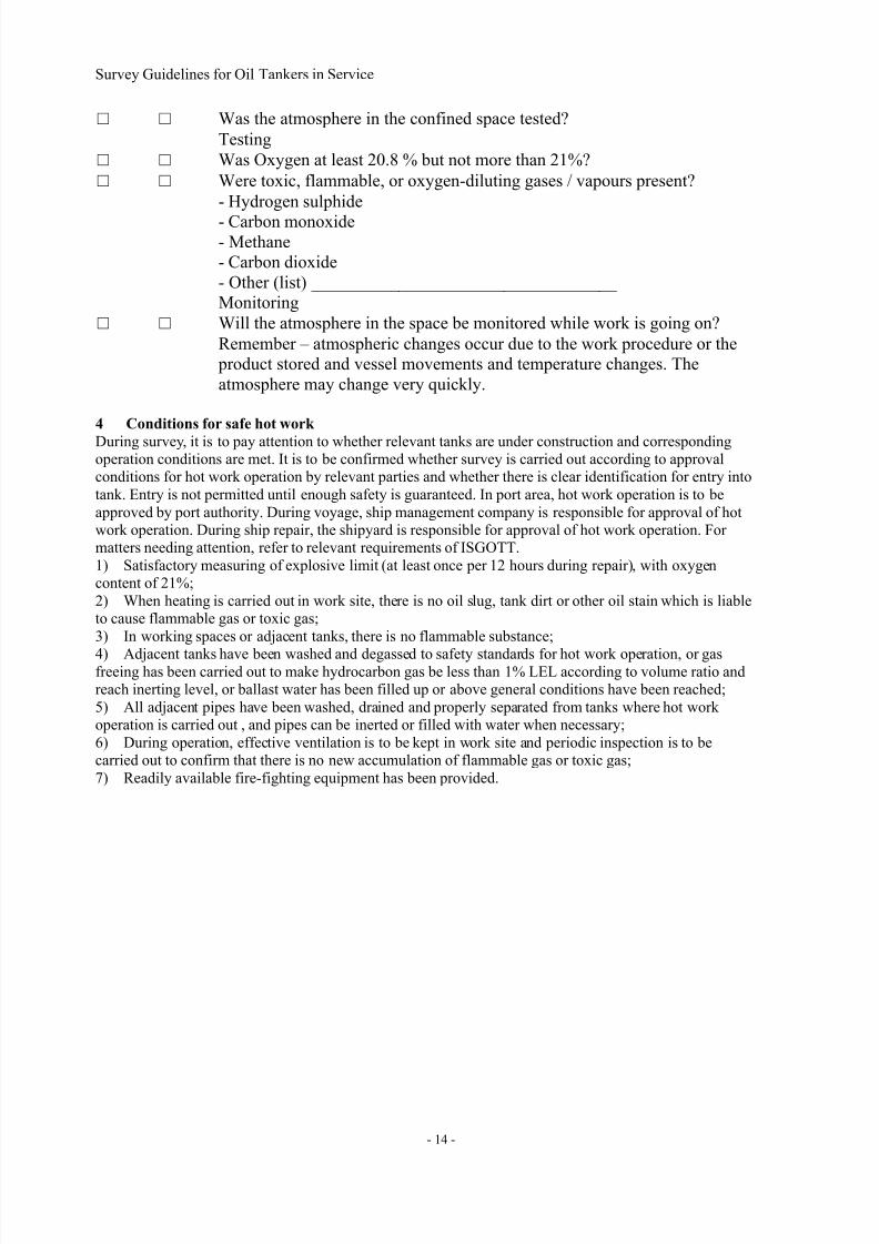
□ □ Was the atmosphere in the confined space tested?
Testing
□ □ Was Oxygen at least 20.8 % but not more than 21%?
□ □ Were toxic, flammable, or oxygen-diluting gases / vapours present?
- Hydrogen sulphide
- Carbon monoxide- Methane
- Carbon dioxide
- Other (list) ___________________________________
Monitoring
□ □ Will the atmosphere in the space be monitored while work is going on?
Remember – atmospheric changes occur due to the work procedure or the
product stored and vessel movements and temperature changes. The
atmosphere may change very quickly.
4 Conditions for safe hot work
During survey, it is to pay attention to whether relevant tanks are under construction and correspondingoperation conditions are met. It is to be confirmed whether survey is carried out according to approvalconditions for hot work operation by relevant parties and whether there is clear identification for entry into
tank. Entry is not permitted until enough safety is guaranteed. In port area, hot work operation is to be
approved by port authority. During voyage, ship management company is responsible for approval of hotwork operation. During ship repair, the shipyard is responsible for approval of hot work operation. Formatters needing attention, refer to relevant requirements of ISGOTT.
1) Satisfactory measuring of explosive limit (at least once per 12 hours during repair), with oxygencontent of 21%;
2) When heating is carried out in work site, there is no oil slug, tank dirt or other oil stain which is liableto cause flammable gas or toxic gas;
3) In working spaces or adjacent tanks, there is no flammable substance;
4) Adjacent tanks have been washed and degassed to safety standards for hot work operation, or gasfreeing has been carried out to make hydrocarbon gas be less than 1% LEL according to volume ratio andreach inerting level, or ballast water has been filled up or above general conditions have been reached;
5) All adjacent pipes have been washed, drained and properly separated from tanks where hot workoperation is carried out , and pipes can be inerted or filled with water when necessary;
6) During operation, effective ventilation is to be kept in work site and periodic inspection is to becarried out to confirm that there is no new accumulation of flammable gas or toxic gas;
7) Readily available fire-fighting equipment has been provided.

7/21/2019 Survey Guidelines for Tankers
http://slidepdf.com/reader/full/survey-guidelines-for-tankers 18/164
Survey Guidelines for Oil Tankers in Service
- 15 -
SECTION 2 SURVEY PREPARATIONS AND MEANS OF ACCESS
It is Owner’s responsibility to provide the necessary facilities for a safe execution of the survey, whichincluding but not limited to the following:1. Tanks are to be completely and thoroughly cleaned, including free from sundries, rust and keep dry, to
reveal corrosion, deformation, fractures, damages, or other structural deterioration, if the area in which
the structures to cropped certainly, requirement of clean in which can be exempted2. Make sure it is safety in tanks, including sufficient oxygen, explosion safe, non-toxicant and provides
sufficient illumination and ventilation. Illumination is sufficient to found structural deterioration,which is confirmed by attending surveyor. Ventilation is to ensure good loop, for that general way is
take place blower fan at the entrance, which is particularly important for the L type or J type ballasttanks and in case of cargo or cargo residues in the cargo hold.
Sufficient and safe means of access is a premise of survey completing in good way, the surveyor is todetermine which way of access.
1. Permanent arrangement. Structure Access Manual is to be recognized by CCS or administration.During survey, existing structure access facility to be used as far as possible.
2. Temporary staging.3. Lifts and movable platforms.
4. Boats or rafts5. Other equivalent means, for example portable Ladders.
Before entering the tank, the following safety measures must be paid enough attention:1. The oxygen content in the tank is sufficient (at least more than 19.6%), there is a security team stead
by at tank entrance, who are responsible for communication and emergency. Every one of inspectorshould take flashlights. When inspection for oil tank or its adjacent spaces is carried out, the torchshould be explosion-proof type.
2. The inspector should be careful not to fall.3. The inspector should pay attention to the impact of falling objects, such as rust, goods adheres at the
top and other damage to the eyes. If necessary, the rust cleaning is to required again.4. Before any examination, all means of access are to be overall inspection. Only one person is allowed
to pass a ladder on time.
5. Attention is paid on slide of temporary. For details, please refer to IACS REC.78.6. Ensure that the means of access has enough support during survey for structural repair in process or
complete repair.
In addition to the above requirements, the following issues are to pay attention when close-up survey
carried out in way of craft:1. During the ship is sailing, mooring, berthing and repair in shipyard, close-up survey for applicable
tanks can carried out in way of craft.2. Only in the case of the surveyor agree, the inspection using of craft is acceptable. surveyor safety
assessment, including weather forecast for the next 2 hours is good weather, the water sloshing in tankcaused by the ship movement no more than 0.25 meters. Prior to inspection, craft should be carefully
checked to ensure that in the case of a gas chamber damaged, craft still have sufficient buoyancy andstability.
3. Ballast water in tanks, in which inspection is carried out using craft should be clean, does not containany traces of oil.
4. Communications systems internal and external of tanks are in good condition, ballast pumps is timelyavailability.
5. During inspection’s process, inspector team must carry oxygen measuring device, measuringinstrument burst, respirators, safety rope, whistle and wear lifejackets in good.
6. Using craft for inspection only applies to tanks in which the deck web frame height is not more than1.5 meters, if the height of deck web frame exceeds this value, this way can be accepted only at the highest
water level, ceiling height under tank top is not less than 3 meters and tank’s coat is in good condition orentrances and access ladder is fitted at each region of between deck web frame.
7. In case of using craft for inspection of structures in area between the deck web frame, the ladderunder the deck at about 2 meters or horizontal platform in way of a higher level than detection water level
and between the fore and rear bulkhead, which is not more than 3m from the deck and have safe passagesto the deck is fitted certainly.

7/21/2019 Survey Guidelines for Tankers
http://slidepdf.com/reader/full/survey-guidelines-for-tankers 19/164
Survey Guidelines for Oil Tankers in Service
- 16 -
During inspection’s process, inspector must be equipped with adequate personal safety equipment:1. Labor suit is worn in good, which is difficult to fire and overall (usually orange).
2. Gloves, if inspection in oil tank, it is recommended to wear plastic gloves.3. Flashlight, which can be backed.
4. As necessary, oxygen measuring / explosive measuring device are took.

7/21/2019 Survey Guidelines for Tankers
http://slidepdf.com/reader/full/survey-guidelines-for-tankers 20/164
Survey Guidelines for Oil Tankers in Service
- 17 -
CHAPTER 3, SURVEYS AND SERVICES PROVIDED BY CLASS ON OIL TANKER
Surveys and Services Provided by Class on Oil Tanker include both classification survey and statutory
survey.The purpose of classification survey is to confirm the effectiveness of hull structural strength and
structural integrity, design requirement fulfillment of electromechanical equipment arrangement and
energy efficiency. IACS URZ10.1 and URZ10.4 have stated the classification survey minimumrequirement of oil tanker hull structure. Similar survey by ship owner or interested party is the measure to promote risk management level, which ought to be encouraged. Nevertheless this survey cannot take place
of related classification survey.What brings to the attention is CCS rule and IACS UR just put forward the basic requirements of
classification survey. Under condition of rule fulfillment, according to the practical situation of ship,surveyor can enlarge the survey scope and extent on occasion. Carry out the survey as much as possible
and make details meticulous, for the purpose of safety operation.Statutory survey is on the basis of authorization, in accordance with international convention andgovernment rules, laws and regulations which are accepted by the flag country, classification society carry
out the survey to ensure the ship fulfill related statutory requirements. To carry out the statutory survey,
special concentration should be paid on the commencement date of convention, tonnage of ship, date of
construction and date of detail requirement.
SECTION 1 DEFINITIONS ABOUT SURVEYS TO OIL TANKER
(a) A Ballast Tank is a tank, which is used solely for the carriage of salt water ballast.(b) A Combined Cargo/Ballast Tank is a tank, which is used for the carriage of cargo, or ballast water as a
routine part of the vessel’s operation and will be treated as a Ballast Tank. Cargo tanks in which water ballast might be carried only in exceptional cases per MARPOL I/13(3) are to be treated as cargo tanks.
(c) An Overall Survey is a survey intended to report on the overall condition of the hull structure anddetermine the extent of additional Close-up Surveys.
(d) A Close-up Survey is a survey where the details of structural components are within the close visualinspection range of the Surveyor, i.e. normally within reach of hand.
(e) A Transverse Section includes all longitudinal members such as plating, longitudinals and girders at thedeck, sides, bottom, inner bottom and longitudinal bulkheads.
(f) Representative Tanks are those, which are expected to reflect the condition of other tanks of similartype and service and with similar corrosion prevention systems. When selecting Representative Tanks
account is to be taken of the service and repair history onboard and identifiable Critical Structural Areasand/or Suspect Areas.(g)Critical Structural Areas are locations which have been identified from calculations to require
monitoring or from the service history of the subject ship or from similar or sister ships to be sensitive to
cracking, buckling or corrosion which would impair the structural integrity of the ship.(h) Suspect Areas are locations showing Substantial Corrosion and/or are considered by the Surveyor to be prone to rapid wastage.
(i) Substantial Corrosion is an extent of corrosion such that assessment of corrosion pattern indicates
wastage in excess of 75% of allowable margins, but within acceptable limits. For vessels built under theIACS Common Structural Rules, substantial corrosion is an extent of corrosion such that the assessment ofthe corrosion pattern indicates a gauged (or measured) thickness between Tnet + 0.5mm and Tnet.
(j) A Corrosion Prevention System is normally considered a full hard coating. Hard Protective Coating is
usually to be epoxy coating or equivalent. Other coating systems may be considered acceptable asalternatives provided that they are applied and maintained in compliance with the manufacturer’sspecification.
(k) Coating condition:
• GOOD condition with only minor spot rusting,• FAIR condition with local breakdown at edges of stiffeners and weld connections and/or light rustingover 20% or more of areas under consideration, but less than as defined for POOR condition,
• POOR condition with general breakdown of coating over 20% or more, or hard scale at 10% or more, of
areas under consideration.Reference is made to IACS Recommendation No.87 “Guidelines for Coating Maintenance & Repairs forBallast Tanks and Combined Cargo / Ballast Tanks on Oil Tankers” which contains clarification of the

7/21/2019 Survey Guidelines for Tankers
http://slidepdf.com/reader/full/survey-guidelines-for-tankers 21/164
Survey Guidelines for Oil Tankers in Service
- 18 -
above.
(l) Cargo Area is that part of the ship which contains cargo tanks, slop tanks and cargo/ballast pump-rooms,cofferdams, ballast tanks and void spaces adjacent to cargo tanks and also deck areas throughout the entire
length and breadth of the part of the ship over the above mentioned spaces.(m) Special consideration or specially considered (in connection with close-up surveys and thickness
measurements) means sufficient close-up survey and thickness measurements are to be taken to confirm
the actual average condition of the structure under the coating.(n) A Prompt and Thorough Repair is a permanent repair completed at the time of survey to thesatisfaction of the Surveyor, therein removing the need for the imposition of any associated condition ofclassification, or recommendation.
(o) General corrosion is defined as IACS REC77, in the reference area, with general breakdown of coating
or hard scale over 70% or more, including pitting corrosion, together with thickness reduction which needto thickness measurement. (p)Excessive corrosion is the corrosion extent exceeding the allowable corrosion limitation.
(q)General Corrosion is presenting unprotected and inattentive scale, uniformly generating in the
no-coating steel structure surface, scale fall off sequent with further corrosion in the exposed steel. Normally after serious thickness damage, the damage could be seen from the exterior.(r)Pitting corrosion is a localized corrosion often found in the water flowing structure or on horizontal
surfaces, especially in cargo oil tanks and in the bottom plating of ballast tanks. Pitting corrosion isnormally initiated due to local breakdown of coating. For coated surfaces the attack produces deep andrelatively small diameter pits that can lead to hull penetration in isolated random places in the tank. Pittingof uncoated tanks, as it progresses, forms shallow but very wide scabby patches (e.g. 300 mm diameter);
the appearance resembles a condition of general corrosion.
(s)Grooving corrosion is a general corrosion normally localized in the adjacent stiffener & plate filletwelding seam and butt welding seam.(t) Confined Space is the location which has the character as follows, used for in and out with no natural
ventilation or not designed for continuously occupation restricted opening.
(u)DWT refers to the deduction of corresponding summer freeboard displacement and light displacementin the water of specific gravity of 1.025, calculated in ton.
SECTION 2 CLASS CHARACTERS AND NOTATIONS
Due to the Specificity of oil tanker, China classification Society provide corresponding different ClassCharacters and Notations
1. Notations Assigned to Type of Oil Tanker
Oil Tanker: Award to single hull oil tankers and double hull oil tankers which not meet the requirement ofdouble hull space. For those double hull oil tankers which not meet the arrangement requirement of rulesand convention, the enhanced survey and thickness measuring requirement should follow the guidance of
IACS URZ10.4.
Oil Tanker, Double Hull: Award to the double hull oil tankers which fulfill the regulation of rules andMARPOL ANNEX I for the double hull arrangement.
Oil Tanker/Chemical Tanker or Chemical Tanker/Oil Tanker: Award to tankers which is available for bothoil production and chemical production.
Oil Tanker/LPG Carrier or LPG Carrier/Oil Tanker: Award to the ships which is available for both LPGand oil production.Ore/Oil Carrier: Award to the ships has two longitudinal bulkheads in the single shell and single deck
along the cargo length area. In addition, most or the whole mid-cargo hold is for ore, the part of the rest
and side tank is for oil.Oil/Bulk/Ore Carrier: Award to ships with double shell, single deck, double bottom, topside tank andhopper tank, and mainly for transporting oil production and bulk dry cargo, such as ore.
2. Notations Assigned to Cargo Feature
F.P.≤60℃ or F.P.> 60℃: Allowable for loading and transporting goods with closed-cup flash point no
more than/ over 60 degree.3. Notations Assigned to Additional Equipment

7/21/2019 Survey Guidelines for Tankers
http://slidepdf.com/reader/full/survey-guidelines-for-tankers 22/164
Survey Guidelines for Oil Tankers in Service
- 19 -
COW: Equipped with crude oil washing. For ships equipped with crude oil washing, pay attention to the
memo and check whether it has been removed in the survey status, which can be found in the Form B.IGS: Equipped with inert gas system.
CBT: Equipped with clean ballast tank, which apply for oil tankers delivered before 6th
July 1996.SBT: Equipped with segregated ballast tank, which apply for oil tankers delivered before 6
th July 1996.
Emergency Towing Arrangements: Equipped with Emergency Towing Arrangements (for oil tankers over
20,000DWT, in consideration of present large oil companies’ requirement, for those over 5,000DWT withthis kind of equipment, special attention on the survey as well)Loading Computer S, I, D: Award to ships equipped with loading computer (strength, intact stability, anddamage stability).
VCS: Vapor control system, award to the ships equipped with cargo tank vapor control system which is in
accordance with the rule requirement.VCT-S: Vapor control system-transit, award to the ships equipped with cargo tank vapor control systemwhich is in accordance with the rule requirement.
Single Point Mooring: Mooring and operation equipment, provide a connection between subsea pipeline
and mooring vessels (FSO, oil tankers, etc.) In case of need, it can be used for transporting fluid. Ship isattached on the topside, with the environmental loading effect, the ship moves round the mooring point.
4.
Notations Assigned to Additional Features PSPC (B,D): Protective coatings in seawater ballast tanks comply with the IMO performance standard,awarded with PSPC (B) notation. Protective coatings in double sides comply with the IMO performancestandard, awarded with PSPC (D) notation. If both standards are fulfilled, the PSPC (B, D) are awarded.
ERS: Emergency Response Service. Award to ships whose owner has sign the emergency response service
agreement with CCS, CCS is responsible for providing the list emergency response service.(1) Pre-establish the database related to ship stability and structural strength;(2) Provide instant assessment of stability, strength and oil spillage when collision at sea, stranding and
oil spillage, etc.
(3) Propose the emergency processing advice to help the ship get rid of danger.
5. Notations Related to Survey ESP: Award to ships carried out of enhanced survey plan based on revised A.744 (18).
In-Water Survey: Award to the ships to the satisfaction of Rules for Classification of Sea-going SteelShips in chapter 12, part5. Under certain conditions, the docking survey can be replaced with it.
SECTION 3 PREPARATIONS TO SURVEY QUESTIONNAIRE
Ensuring the safe operation is the responsibilities and obligations of ship owner. Qualified survey control
is the important part of ship operating risk management. Sufficient preparation is the requirement tocomplete the survey. Before the start of survey, the owner should understand the survey requirement and
make the survey scheme, then submit the survey plan Questionnaire and ESP survey plan, meanwhile prepare to be ready for survey.
Before the survey, surveyor should read the related data of the ship, including ship type character, surveyguidelines, historical damage record and similar data analysis of the ship type history. Together with the
detail “survey guidelines”(if possible), review the survey plan and confirm survey scope, survey key pointand survey implementation model.When doing special survey or intermediate survey following the scope of special survey (for over 10 years
of age) for all oil tankers with ESP notation, ship owner need to submit survey questionnaire which should
provide to CCS 3 months in advance. In order to make the survey plan precisely and instruct thedevelopment of survey, the content of the questionnaire should be detailed. Preparation refers to CASsurvey questionnaire see CCS Guidelines for Surveys of Condition Assessment Scheme (CAS) for
Existing Oil Tankers.
Survey questionnaire includes at least following contents:1. Particulars of ship2. Provide access for thickness measurement and close-up survey
3. Cargo stowage history, especially for the goods contains plenty of sulphur, heat-needed and tank
washing history, related data like goods character, loading time, washing medium and washingtemperature should be the efficient part of the questionnaire.

7/21/2019 Survey Guidelines for Tankers
http://slidepdf.com/reader/full/survey-guidelines-for-tankers 23/164
Survey Guidelines for Oil Tankers in Service
- 20 -
4. Ship owner self-checklist should cover the coating protection, coating condition, structural defect and
structural damage history of all ballast tank and cargo oil tank (cargo oil /ballast tank is regarded as ballasttank ). Structural defect and structural damage history should be detailed description and be the valid part
of the questionnaire. To be concerned that the survey result should be filled in the questionnaire, no matterthe fore peak is ballast tank or not.
5. Detail report of hull structural defect found in the past 3 years.
6. Detail report of non-conformance term in the past 3 year’s safety management system.7. Contact details of TM companies.8. Other necessary documents provided by shipping company.
SECTION 4 PREPARATION OF SURVEY PROGRAMME
1 month before the planed survey, ship owner should finish the writing of survey plan and put forward to
classification society for approval. According to the application, CCS could participate in the survey planwriting. Preparation refers to CAS survey questionnaire see CCS Guidelines for Surveys of Condition
Assessment Scheme (CAS) for Existing Oil Tankers.After the approval of survey plan, the survey is on start. The survey plan includes at least following
contents:1. Particulars of ship
2. Hull structural drawings and related reference, the reference should be as detailed as possible, includessurvey information, survey status, report of condition assessment /thickness measurement of last survey,
classification survey report in the past 3 years, survey questionnaire and IGS system information, etc.3. Arrangement of Crew Accommodation4. Coating and corrosion protective system status.
5. Provide good survey condition, which need to be clean, ventilated, non-poisonous and well-lit.6. Access for the structural survey and access auxiliary facilities should follow the CCS rules and make the
arrangement. Before the survey, access should been checked and assessed to ensure the safety and positioned.
7. Related testing equipment such as thickness measuring instrument, NDT equipment, Oxygen meter,
flammable gas detector, breather and so on.8. Survey scope and requirement: CCS rules bring out the basic survey scope requirement of completeinspection and close-up examination. On the basis of survey questionnaire, if bad coating condition,
structure defects and repair record show that structure defects were found several times and may occur insome other same type ships, the complete inspection and close-up examination should expanded and this
part should be listed.9. Compartment structures test requirement: CCS rules bring out the basic survey scope and requirement
of compartment structures test, if deformation, buckling, crack, excessive corrosion or large scale repairwere witnessed on board, the scope should be expanded and this part should be listed.
10. Thickness measurement: CCS rules bring out the basic survey scope requirement of thicknessmeasurement. On the basis of survey questionnaire, if a structure has been found to be general corroded,
substantially corroded, buckling deformation and may occur in some other same type ships, the completeinspection and close-up examination should expanded and this part should be listed.
11. Corrosion and wastage control of hull structure: CCS brings out all kinds of the predetermined limitsof structure corrosion.
12. Contact details of TM companies: CCS has established a perfect evaluation system of TM companies’qualification, capacity and integrity. List of recognized TM companies can be obtained in the website of
CCS.13. The historical structural damage data of the ship and similar ships: this data is the major part to ensure
the key point of survey. As a result, ship owner should collect this data as much as possible. MeanwhileCCS will provide guidance.
14. The structure substantially corroded showing in historical survey: CCS will assist the owner tocomplete this part.15. Structure critical area and suspicious area: CCS will assist the owner to complete this part
16. Other related documents

7/21/2019 Survey Guidelines for Tankers
http://slidepdf.com/reader/full/survey-guidelines-for-tankers 24/164
Survey Guidelines for Oil Tankers in Service
- 21 -
SECTION 5 BRIEF INSTRUCTIONS TO CLASS SURVEY AFTER
CONSTRUCTION
1. Class Survey Planning
Class survey for oil tanks is to ensuring the hull structures, machinery equipments and electrical
equipments to be in normal condition, enhanced survey programme (ESP) is mainly to evaluate the
coating condition and corrosion of structural members, to forecast when the coating will not be in goodcondition and substantial corrosion will be occurred.Appropriate survey arrangements are to carry out a survey well.
1.1 Documentations ReviewPrior to survey, the Surveyor is to collect and examine the documentation onboard as far as possible as a
basis for the survey. The information as following:
1) Ship drawings, including loading manual and loading computer manual;2) Survey reports, owner’s inspection report, checking records by oil company and other relevantinspection reports;
3) Repairing history and alternating records etc.
4) PSC records;5) SMS audit reports;6) Approved ESP, including categories and particulars of loaded cargo, ballast history, detailed
information of crude oil washing tanks and sea water washing tanks, structural corrosion standard and so
on;7) The latest EHS report;8) CAS statement and CAS report;
9) CAP report;
10) Any other information that will help identify suspect areas and critical structural areas.11) Besides above, due to high risk of oil tanks, CCS and other RO have made some detailed provisionsmore than general cargo ships. Relevant information regarding to inspection for oil tanks to be kept on
board as following:
1. As the request of ship’s owner and under the authority of Administration, CCS can approve relevantmanuals, such as following:
1) Ship oil pollution emergency plan(SOPEP)/ Ship marine pollution emergency plan(SOMEP);2) Oil record book;
3) Crude oil washing manual, as applicable;4) ERS documents, as applicable;5) ODME manual;
2. Statement1) Cargo hose pipe/ cargo piping test reports(every year);
2) Periodical inspection report of Oil content meter and ODEM;3) Pressure adjusting of PV valves;
4) Product certificates of emergency towing equipments;3. Survey Status provided by CCS
4. Unscheduled test records of Alcohol and drugs;
5. Oil company requires the ship to be provided class and statutory certificates with at least twomonths validity before loading the cargo.6. Refer to chapter eight of this guideline for requirements of oil company.
1.2 Survey Planning MeetingPrior to commencement of any part of the special and intermediate survey, a survey planning
meeting is to be held between the attending surveyor(s), the owner’s representative in attendance, thethickness measurement company operator (as applicable) and the master of the ship or an appropriately
qualified representative appointed by the master or Company for the purpose to ascertain that all thearrangements envisaged in the survey programme are in place, so as to ensure the safe and efficient
conduct of the survey work to be carried out. Main contents of the meeting are as following:1) The work to be developed at the next stage;2) Instruction of survey team;
3) Co-operation of relevant parties;4) Requirements of ensuring the safe conduct of the survey work;5) Questions raised at previous stages and rectification;

7/21/2019 Survey Guidelines for Tankers
http://slidepdf.com/reader/full/survey-guidelines-for-tankers 25/164
Survey Guidelines for Oil Tankers in Service
- 22 -
6) Survey content of next stage, such as overall/close-up survey items, structural test, thickness
measurement, efficiency of relevant inspecting equipments etc.;7) Environment requirements, such as lighting, cleaning, ventilation, means of safe access etc.
8) Repairing techniques and technical standards to be provided beforehand;9) Other point to note;
Survey planning meeting to be achieved in line with a record as far as possible, and the record to be
confirmed by each other.1.3 Requirements of Internal Examinations to TanksRequirements of internal examinations to tanks corresponding to different kinds of survey are not the same,for more details please refer to the annex one- Minimum Requirements of the Internal Examinations to all
the tanks of self-propelled integrated Oil Tankers. If ship’s condition found poorly, such as coating is poor,
structural defects found, repairing records shown structural defects found frequently or indicated somedefects may be occurred in other same type ships , scope of overall survey and close-up survey to beextended and recorded;
1.4 Requirements of Thickness Measurements
Requirements of thickness measurements to be seen in annex one, and more attention to
thickness measurements of general corrosion, substantial corrosion and close-up area to be paid,
for more details, please refer to CCS <Rules for Classification of Sea-going Steel Ships > and
<Guidelines for thickness measurements>. If general corrosion, substantial corrosion, buckleddeformation found in the tanks or indicated excessive corrosion in some spaces may be occurred
in other same type ships, scope of thickness measurements to be extended and recorded.
2. Notes of class surveyClass survey including annual survey, intermediate survey, special survey, external inspection of ship bottom(docking survey), damage and repair survey.
2.1 Annual survey
Compare with general cargo ship, more attention to be paid to inspection of cargo maintenance and
handling systems for oil tanker ,such as following:
2.1.1 Inspection of exposed deck area
1 Cargo tank openings including gaskets, covers, coamings and flame screens. Examination of theintactness of gaskets, corrosion condition of hatch coamings, completeness of closing devices, provision ofmeasures to prevent sparkle caused by collision and the intactness of flame screen of inspection hole.
Generally speaking, flash screens is made up of stainless steel or copper, it is acceptable if the flowingarea is 1.5 times of pipe section area and the flash screens can prevent fire going through. The standard of
the flash screens used at present is Chinese shipping industry standard- holes of flash screens for oil tankto be at least 12x12/cm2, if double flash screens used, the quantity of holes to be at least 8x8/cm2, that is a
little less than the requirement of USCG. USCG requires at least 30 holes per square inches, if the holesare 20 and less, double flash screens to be used, the gap of two flash screens to be between 12.7~38.1mm.
2 Examination of cargo tank pressure/vacuum valves and flame screens. The adjusting record of PVvalves to be kept on board.
3 Examination of cargo tank venting, purging, gas-freeing and other ventilation systems. Pay attention
that crude oil tankers and tankers carrying other petroleum products in bulk, of 500 gross tonnage or above,loaded with cargo having a flashpoint not exceeding 60ºC and whose Reid vapour pressure is below thatof atmospheric pressure are to be provided with an auxiliary venting system. Visual inspection is to be
given for main and auxiliary venting system and their venting heads.4 Examination of flame screens on vents to all bunker, oily ballast, oily slop tanks and d cofferdam.
5 Examination of cargo, crude oil washing, ballast and stripping systems both on deck and in cargo pump rooms, and bunker and vent piping systems on deck including vent masts and headers. Conductvisual inspections for the above-mentioned pip systems, including valves on pipes, discharges and ground
strap for the purpose of preventing hazard of electrostatic discharge
6 Inspection of fast cut of cargo oil pipes and its valves;7 Oil tanker of 500 gross tonnage or above, loaded with cargo having a flashpoint not exceeding 60ºC,integrality of safe access fitted to bow to be inspected, such as handrails, supporting pillars and wire ropes
etc., the material of access to be noncombustible;
8 Oil tanker of 20,000 gross tonnage or above, emergency towing equipments to be inspected to normalwork condition, including inspection of recovery installation, short towing ropes, leading rope equipments,

7/21/2019 Survey Guidelines for Tankers
http://slidepdf.com/reader/full/survey-guidelines-for-tankers 26/164
Survey Guidelines for Oil Tankers in Service
- 23 -
towing points and brackets of that, ensuring the floating marks with indicator light in good working
condition;
2.1.2 Examination of cargo pump rooms and pipe tunnels,1. Confirming that no potential sources of ignition such as loose gear, excessive bilge accumulated oil,
excessive oily vapour and combustible materials, etc., are present in or near the cargo pump room and thataccess ladders are in good condition.
2. Confirming that installed pressure gauges on cargo discharge lines and level indicator systems areoperational: conduct visual inspection and check if the pressure gauges are regularly calibrated
3. Examination of the condition of all piping systems in the cargo pump room so far as practicable:including visual inspections for cargo, ballast, slot and vapour piping, etc
4. Confirming that the pump room ventilation system is operational, ducting intact, dampers operationaland screens are clean.
5. Examination, so far as practicable, of cargo, bilge, ballast and stripping pumps in the cargo pumproom for excessive gland seal leakage, verification of proper operation of electrical and mechanical remote
operating and shutdown devices and operation of pump room bilge system, including the remote systemand local operating systems and checking that pump foundations are intact.
6. Examination of all pump room bulkheads for signs of leakage or fractures, and in particular, thesealing arrangements of all penetrations in these bulkheads
7. Oil tanker of 500 gross tonnage or above, loaded with cargo having a flashpoint not exceeding 60ºC ,confirming that temperature sensing devices and audible and visible alarms in pump rooms are in goodcondition, if applicable.
8. In the pump room, and the cargo, ballast and striping pumps driven by shaft passing through pump
room bulkheads, the bulkhead shaft glands, bearings and pump casings are to be fitted with temperaturesensing devices which are capable of initiating continuous audible alarm signals arranged in cargo controlrooms or pump rooms
9. Oil tanker of 500 gross tonnage or above, loaded with cargo having a flashpoint not exceeding 60ºC ,
confirming that bilge level monitoring devices and alarms in pump rooms are in good condition (ifapplicable). All pump rooms are to be installed with bilge level monitoring devices and alarm devices atappropriate positions. Bilge high level alarm is acceptable as a substitute for bilge level monitoring device
10. Oil tanker of 500 gross tonnage or above, loaded with cargo having a flashpoint not exceeding 60ºC ,
examination of systems for continuously monitoring concentration of hydrocarbon gas (if applicable). Asystem for continuous monitoring of the concentration of hydrocarbon gases is to be fitted on all oiltankers constructed before 1 July 2002. Sampling points or detector heads are to be located in suitable
positions in order that potentially dangerous leakages are readily detected. When the hydrocarbon gas
concentration reaches a pre-set level which is not to be higher than 10% of the lower flammable limit, acontinuous audible and visual alarm signal is to be automatically effected in the pump-room and cargocontrol room to alert personnel to the potential hazard. However, existing monitoring systems already
fitted having a pre-set level not greater than 30% of the lower flammable limit may be accepted. A system
for continuous monitoring of the concentration of hydrocarbon gases is to be fitted on all tankersconstructed on or after 1 July 2002. Sampling points or detector heads are to be located in suitable positions in order that potentially dangerous leakages are readily detected. When the hydrocarbon gas
concentration reaches a pre-set level which is not to be higher than 10% of the lower flammable limit, acontinuous audible and visual alarm signal is to be automatically effected in the pump-room, machinery
control room, cargo control room and navigational bridge to alert personnel to the potential hazard.11. Oil tanker of 500 gross tonnage or above, loaded with cargo having a flashpoint not exceeding 60ºC ,
checking interlock between lighting and ventilation (if applicable): For oil tankers constructed on or after1 July 2002, except emergency lighting, the lightings in all cargo pump rooms are to be interlocked with
ventilation so that the turn on of lighting will activate ventilation. The failure of ventilation system is notto put out lighting.
12. Examination of the fixed fire-fighting system for cargo pump rooms, and confirming, as far as practicable and when appropriate, the operation of the remote means for closing the various openings.
2.1.3 Others
1. Checking last ESP document and relevant files such as EHS report, confirming the extent of internalinspection of tanks;
2. Checking the deck foam system, including the supplies of foam concentrate and testing that the
minimum number of jets of water at the required pressure in the fire main is obtained, when the system isin operation, and confirming that deck sprinkler system is in good working condition.

7/21/2019 Survey Guidelines for Tankers
http://slidepdf.com/reader/full/survey-guidelines-for-tankers 27/164
Survey Guidelines for Oil Tankers in Service
- 24 -
3. Confirming that a corrosion prevention system is fitted in dedicated ballast water tanks of oil tankers.
4. Oil tankers of 500 gross tonnage or above, the keels of which are laid on or after January 1, 2005,confirming that permanent means of access in tanks is to be in good condition;
5. Confirming, when appropriate, the measures provided for a ship to regain steering capability in theevent of a single failure;
6. Examining the pressure indicator of main cargo piping and level indicator systems including manual
sounding devices in the cargo tanks;7. Examination of all electrical equipment in dangerous zones, piping and stopping valves of cargotanks.8. Checking inert gas overboard discharge devices;
9. Examination of the fixed fire-fighting system for cargo pump rooms, and confirming, as far as
practicable and when appropriate, the operation of the remote means for closing the various openings;10. Examining two portable instruments for measuring oxygen and flammable vapour concentration, andconfirming the periodical inspection records kept on board;
11. Examining portable or fixed instruments for measuring flammable vapour concentration in fore peak
tank and double hull spaces;12. Other appropriate system, such as vapour recovery system etc.
2.2 Intermediate Survey
Since the intermediate survey replaces one annual survey, the requirement of annual survey should befulfilled. Besides, the compartment internal examination should be approved, detail see the annex 1.
For Oil tanker which is 10 years and upward, the cargo area structural survey should follow the specialsurvey scope. Unless the surveyor consider there is a need, as if many structural defects or strength
allowance not fulfilled in the last longitudinal strengthen assessment, otherwise the longitudinal strengthassessment and apartment structural test are not compulsory.
The survey according to special survey scope for oil tankers of 20,000 DWT and forwards should becompleted by two surveyors.
Survey scope and extent1. Oil tanker, which are less than 10 years of age.
1.1 Inspect all the pipe systems, including the cargo handling pipe system, crude oil pipe system, fuel pipesystem, ballast pipe system, steam heating pipe system, cargo ventilation/vent piping(including mast risers
and vent pipe head and ventilation pipe system’s emptier where applicable). If obvious defects areobserved, such as partially serious thickness diminution and pitting corrosion, related pipe system pressure
test or thickness measurement should be carried out and make the record.1.2 The ventilation system spares in cargo area should be inspected, including duplicated system, spare
motor and impeller, etc.1.3 The survey of electrical equipment in gas-hazardous zones, if the ship operator has kept the continuousinsulation measurement record and the result is fine, the survey is not compulsory.
1.4 Windlass verification process
1.5 Inspection and simulation test of fixed fire-extinguishing systems1.6 Internal examinations in all ballast tanks are required for single hull oil tankers aged 5-10 years. Ifapartment is in bad coating condition, meanwhile the structural defects and repair record shows that
structural defects had been seen for several times as well as in the same type ships, necessary thicknessmeasurement and structural test should be arranged, verified and recorded.1.7 Internal examinations in all ballast tanks are required for double hull oil tankers aged 5-10 years. If noobvious defects are found during the survey, the hard coating can be confirmed as “good” condition. If
apartment is in bad coating condition, meanwhile the structural defects and repair record shows that
structural defects had been seen for several times as well as in the same type ships, close-up inspectionshould be arranged and recorded. If following situations are happened in the ballast tank, memo is requiredto suggest internal examination in the sequent annual surveys. Besides, thickness measurement should be
decided after the internal examination result.※Hard coating is not applied during construction.※Soft coating has been applied.※Substantial corrosion is found within the tank
※The hard protective coating is found to be in less than GOOD condition and the hard protective coatingis not repaired to the satisfaction of “Guidelines for coating survey, assessment and repair of hull

7/21/2019 Survey Guidelines for Tankers
http://slidepdf.com/reader/full/survey-guidelines-for-tankers 28/164
Survey Guidelines for Oil Tankers in Service
- 25 -
structures”.※Except for the above requirement, the suspicious area stated in the former survey should be inspected.1.8 Inspection of coating condition, if the coating condition is changed, the surveyor need to reissue the
summary report of coating conditions of tanks.1.9 Arrange inspection and thickness measurement in the suspicious area of structure which is mentioned
in the past survey. Meanwhile confirm the new suspicious area and high potential corrosion acceleration
area based on the survey.
2.3 Docking Survey (Outside Bottom’s Survey)There should be two docking survey during one periodical survey, the maximum interval should not
exceed 36 months.
Dry-docking survey is the part of the special surveyThe intermediate survey is normally carried out with docking survey. For oil tankers no more than 15years, if awarded with “In-Water Survey” class notation, the docking survey can be replace with In-Water
Survey, otherwise the permission of CCS Headquarter is in need. For oil tankers over 15 years, the
docking survey must be dry-docking survey.Special survey or intermediate survey under the special survey scope are allowed to be carried out instages, close-up inspections and thickness measurements of the space under light waterline should be
finished together within the docking survey period. If some compartment is divided by the light loadingline, the close-up inspections and thickness measurements should be finished before the end of dockingsurvey.The docking survey of oil tankers should not only fulfill normal docking survey, much more concentration
should be focused on the detailed inspection of IGS washing tower and underwater discharge outlet under
deck water seal.
2.4 Special Survey and the Survey in Scope of Last Special Survey
Except for the annual survey items, special survey should combine with docking survey. Thence docking
survey is the efficient part of special survey, thickness measurement should follow the thicknessmeasurement guidance and Minimum Requirements of the Internal Examinations to all the tanks inappendix 1. Be concerned that in the thickness measurement of 4
th special survey and sequence special
survey, the regulation “cargo area loading waterline and exterior loading waterline shell plate” is amendedto “all loading waterline shell plate”. 15 months before the due date of special survey, the thicknessmeasurement report could be accepted if confirmed by surveyor.Oil tanker with 10 years and upward, if L is over 65m, the longitudinal strength assessment should
combine with special survey. Section modulus calculation should base on the CCS recognized softwareCOMPASS. Assessment detail techniques refer to the CCS rules part 1 chapter 5 appendix 2.
Beam section modulus required by rules should be the minimum value W0 in mid-ship and sectionmodulus combined by wave bending moment and still water bending moment. In consideration of the
historical evolution of structure standard, ships built before 1996 and L no more than 90m should use themid-ship minimum section modulus W0 as the rule required section modulus.
The oil tanker with L over 130m should calculate the deck section static moment based on the thicknessmeasurement report, if design value is 10% less than the smaller value, there is no need to check the
section modulus. If any deck section static moment no meet the requirement (namely less than the 90% ofthe rule required value). Within the 0.5L of the mid-ship, choose several section which covers ballast tank
and cargo tank in the cargo area, when cut for change, the longitudinal renew length should not less than 2strengthened frame. If choose cover plate method under the special consideration, the plate in the original
substantial corrosion area should get prior replacement.When doing longitudinal strength assessment of single hull oil tanker, based on the requirement of
MEPC.147 (54), check the deck longitudinal fillet welding seam and make sure the effective height no lessthan plate or component surface, recommendation for using UT.
For the section structural thickness measurement carried out for longitudinal strength assessment, theresult should fulfill the rules for classification of sea-going steel ships, the section should be the suspiciousthickness losing area, and avoid the partially renewed or strengthened area, especially for deck girder or
bottom girder within the 0.1D area. Each plate need to be measured at least one point in one frame space.
For oil tankers of 10 years and upwards with deadweight over 20000, the special survey should be taken by 2 surveyors. In order to check the condition, during the special survey or same scope survey that all

7/21/2019 Survey Guidelines for Tankers
http://slidepdf.com/reader/full/survey-guidelines-for-tankers 29/164
Survey Guidelines for Oil Tankers in Service
- 26 -
ventilator head in the hull open air need to be overhauled.
2.5 Damage Survey and Repair Survey
When the ship is damaged, owner should inform classification in time, then classification society decideswhether carrying out the damage survey or not. Inappropriate delay or missing report may result in the
suspending, canceling of ship class, as well as the non-conformity of ISM system. The description of
defects should be detailed and accompanied by sketch, drawing and photos. Any corrosion exceedingstandard or buckling, serious groove corrosion and crack that may result in hull structural strength need to be repaired in time. Focus on the following area:1) Bottom structure
2) Side structure
3) Watertight bulkhead4) Hatch cover and coaming of Crude oil /Core combination carrier5) Deck structure
Double hull oil tanker also includes the following structure:
1) Inner bottom structure2) Inside structure3) Longitudinal bulkhead structure
After observing the defects in survey, try to do further check in the similar components or location in caseof the defects exist. If possible, MT and PT should be used for the checking. If the repair condition islimited, after the necessary measurement like assessment, providing sailing restricted condition, unloadingor interim repair, the ship is allowed a single trip to next harbor for repair.
If the structural defects belong to the inappropriate ship management and maintenance, surveyor will
report the defects to the Headquarter. If the ISM certificate is issued by CCS, the defect report will beanalyzed furthermore, the result will tell whether an ISM additional verification is needed. If the ISMcertificate is not issued by CCS, the defect will forward to ISM certificate issuing organization.
SECTION 6 STATUTORY SURVEYS
At present, CCS has accepted various countries’ authorization of statutory survey, the scope covers every
part of SOLAS convention, LL convention, COLREG convention, ILO convention and MARPOLconvention.According to the classification rules: Classification survey is in accordance with the statutory survey
simultaneously. As a result, classification survey is taken when doing statutory survey. As if the
classification special survey cycle are restricted in less than 5 years for the reason of technical condition orstructural condition, statutory survey renewal survey should in accordance with classification specialsurvey, related statutory regular survey should adjust to it as well.
The anniversary date of statutory survey determine the date of annual survey, intermediate survey and
renewal survey, as if the annual survey, intermediate survey and renewal survey are completed beforespecified time limit(namely before 3 months of the anniversary date), the anniversary date need to getrevised to ensure all kinds of regular survey not exceeding the specified period.
To ensure the safety, IMO bring out CAS requirement for present oil tanker, namely all 5000DWT orinternational shipping oil tankers contracted, keel laid or delivered before 6
th July 1996 should take CAS
survey combined with intermediate survey, except for the oil tankers as follows:1. Oil tankers which fulfilled the double hull requirements of MARPOL convention.
2. Except for the side tank breadth and minimum height of double bottom space which not meet therequirement of MARPOL convention 19.3.1, 19.3.2, 19.4 and 19.5, under this situation, the protective
height in double bottom central line should be B/15 or 2m, the protective distance of side tank should be760mm.
3. In accordance with the hydrostatic balance loading requirement of MARPOL convention 19.4 ormethod in 19.5 which is confirmed by MEPC. In terms of the detail requirement of CAS survey, refer to
the “CCS Guidelines for Surveys of Condition Assessment Scheme (CAS) for Existing Oil Tankers”

7/21/2019 Survey Guidelines for Tankers
http://slidepdf.com/reader/full/survey-guidelines-for-tankers 30/164
Survey Guidelines for Oil Tankers in Service
- 27 -
SECTION 7 CAP SURVEY
The aim of CAP is to provide applicant a ship status technical document and declaration of structural
strength, mechanical equipment and ship life maintaining, which is to confirm the ship fulfill the CCStechnical standard of present rules, this is to be provided to the cargo owner when renewing the lease or
for a new lease. CAP is technical service for the applicant, which is appropriate for the tankers of 15 years
and upwards. In terms of the detail requirement of CAP survey, refer to the Guidelines for ConditionAssessment Procedure (CAP) for Existing Ships.

7/21/2019 Survey Guidelines for Tankers
http://slidepdf.com/reader/full/survey-guidelines-for-tankers 31/164
Survey Guidelines for Oil Tankers in Service
- 28 -
CHAPTER 4, INSPECTIONS TO STRUCTURES OF OIL TANKER
In recent years, with the deepening of structural studies, technology of structural inspection has been
considerable development. And fully understand the structural mechanical characteristics and structuralcorrosion mechanism, accurately understand the structural inspection’s requirements, it is a prerequisite to
carry out inspection of the hull structure.
SECTION 1 INSPECTION TO HULL STRUCTURE
1. Loads
The deck structures of oil tank mainly resist longitudinal bending stress and lateral load caused by cargoand waves. Due to deck area is farther from the neutral axis, bending stress suffered is higher. For
machinery and equipment fitted on deck, the waves on deck, wave slamming loads and other local loadsalso be considered.
The bottom structure is mainly resist itself bending stress of longitudinal hull girder, as well as cargo , ballast , water pressure, etc. cyclical local loads. Due to the bottom area is farther from the neutral axis,
bending stress suffered is higher too. Bottom structure suffered lateral load obviously when alternate usingof side tank and centre tank.
Side shell, longitudinal and transverse bulkheads mainly resist attacked load in internal tank as well asexternal attack wave loads and other dynamic loads. And side shell, longitudinal bulkheads as the web of
hull girder also withstand shear forces and pass along ship length, and the transverse bulkheads andtransverse web frame withstand and pass the lateral shear forces.Bow structures mainly resist attack and deck wave, the area in way of light waterline to forecastle deck or
forecastle deck plating should be paid more attention in survey. For stern structures, the effects of
vibration and cavitation erosion are more considered, structural corrosion and outlet of various types of pipeline should be paid more attention in survey.The force of the hull structure is usually combined effects of various factors, fully aware of this is great
benefit for inspection.
Accurately understand and grasp the force in structure is very important for accurately determining the key point of structural inspection, critical structural areas, structural hard points and hot spots. Duringinspection, under analysis in accordance with rules of the China Classification Society, combined with the
ship's "Inspection instructions" (if any ), maintenance and repair history, discovery and judgment regionalwhere structural defects may produced, type of structural defect, the causes of defect and defect
treatment’s requirements. Following figure is a stress cloud chart as example showing mid-sectionstructure of VLCC tanker in different set of cross tie. The chart shows stress cloud of mid-section of some
two ships. The the high stress areas in chart should be focused on.

7/21/2019 Survey Guidelines for Tankers
http://slidepdf.com/reader/full/survey-guidelines-for-tankers 32/164
Survey Guidelines for Oil Tankers in Service
- 29 -
2. Structure’s Defects Analysis
Major job for structural inspection of oil tank is to confirm the structural strength of the hull, structural
integrity and tightness. The key is to accurately understand the force in structure, the injury patterns andinjury reasons. Focus on grasping the fatigue damage, especially fatigue damage characteristics of highstrength steel.
Causes of structural defects are variety. There are excessive corrosion , design defects, material defects ,
workmanship defects, welding defects , yield , fatigue, bad weather , unreasonable and incorrect loadingand unloading ballast water operations at sea, collision , etc. Above defects are usually caused due touncertain external loads such as wave loads, unreasonable operations by crew, using unreasonable
construction / repair standards and lack of quality control in shipyard construction process.For manifestation of defects, there are material wastage, buckling, dents, deformation and crack damage.These defects are usually caused by a variety of factors working together and which affect each other, suchas cracks commonly appear at the beginning or end of a run, or rounding corners at the end of a stiffener
or at an intersection; After structure excessive corrosion, the structure of reduced thickness is ability to
crack and drop when subjected to external force, resulting in a large number of cracks and buckling appear;Material which have buckled severely is easy to make coating layered, break, thus resulting in seriouscorrosion.
The Typical Defects Types are as following table:
Table 4.1 Typical Defects TypesItems Corrosion Buckling Cracks
Longitudinal material -upper deck plating and decklongitudinals
-welding connections betweenstructural elements, deck
longitudinal to deck plating in particular-scallops and openings for
drainage-webs of longitudinals on long. bulkheads, longitudinal, high
rates and localized corrosion(grooving)
-flanges of bottom longitudinal-bottom plating, erosion near
suction-longitudinal bulkhead plating
-upper deck plating-upper deck longitudinal
-bottom plating-bottom longitudinals
-upper and lower part oflongitudinal bulkhead plating
-girder in deck and bottom
- at discontinuities-at openings, notches
-at connections withtransverse elements
Transverse webframes
-Upper part, connection to deck-Just below top coating
-web plating-Brackets
-Connections with longi.Elements
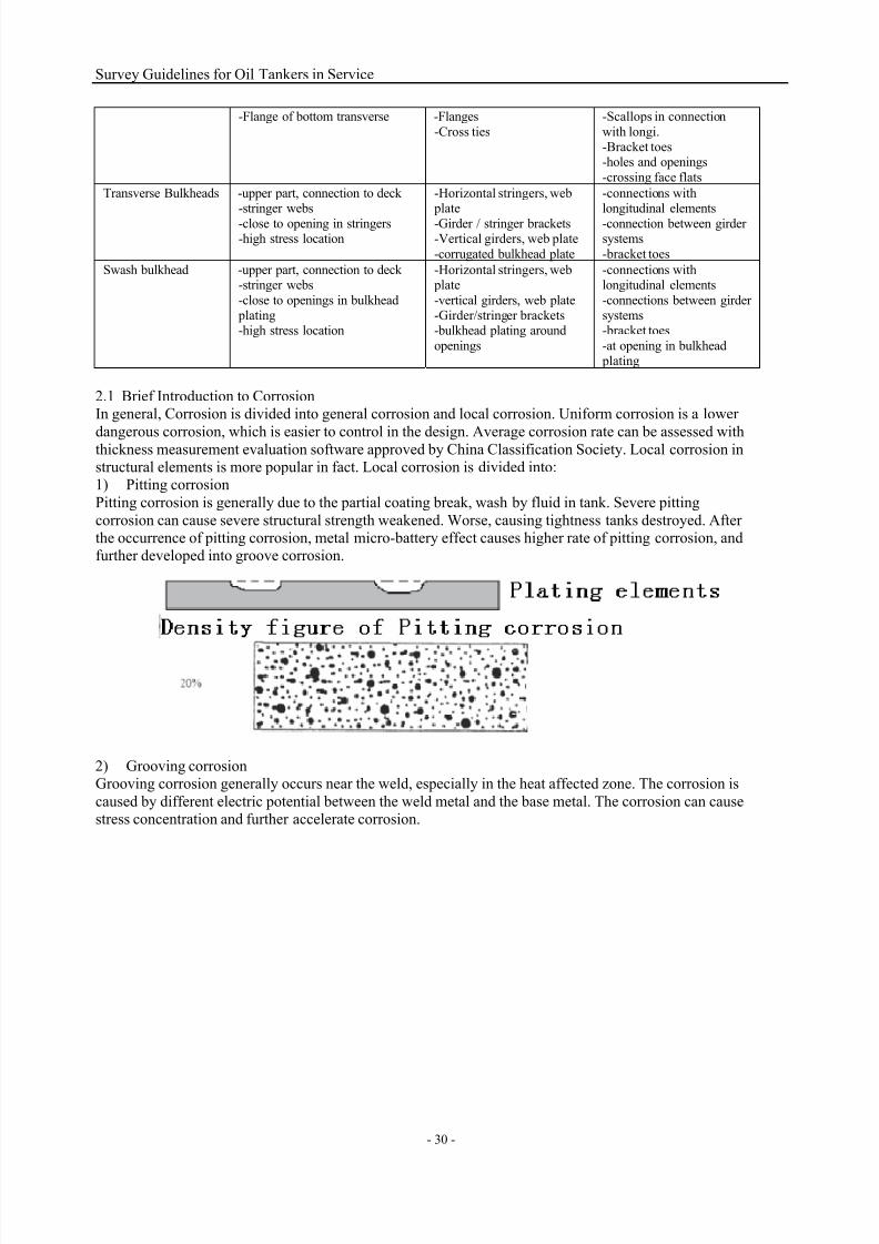
7/21/2019 Survey Guidelines for Tankers
http://slidepdf.com/reader/full/survey-guidelines-for-tankers 33/164
Survey Guidelines for Oil Tankers in Service
- 30 -
-Flange of bottom transverse -Flanges
-Cross ties
-Scallops in connection
with longi.-Bracket toes-holes and openings
-crossing face flats
Transverse Bulkheads -upper part, connection to deck-stringer webs
-close to opening in stringers-high stress location
-Horizontal stringers, web plate
-Girder / stringer brackets-Vertical girders, web plate
-corrugated bulkhead plate
-connections withlongitudinal elements
-connection between girdersystems
-bracket toes
Swash bulkhead -upper part, connection to deck-stringer webs
-close to openings in bulkhead plating-high stress location
-Horizontal stringers, web plate
-vertical girders, web plate-Girder/stringer brackets-bulkhead plating around
openings
-connections withlongitudinal elements
-connections between girdersystems-bracket toes
-at opening in bulkhead plating
2.1 Brief Introduction to CorrosionIn general, Corrosion is divided into general corrosion and local corrosion. Uniform corrosion is a lower
dangerous corrosion, which is easier to control in the design. Average corrosion rate can be assessed withthickness measurement evaluation software approved by China Classification Society. Local corrosion instructural elements is more popular in fact. Local corrosion is divided into:1) Pitting corrosion
Pitting corrosion is generally due to the partial coating break, wash by fluid in tank. Severe pitting
corrosion can cause severe structural strength weakened. Worse, causing tightness tanks destroyed. Afterthe occurrence of pitting corrosion, metal micro-battery effect causes higher rate of pitting corrosion, andfurther developed into groove corrosion.
2) Grooving corrosionGrooving corrosion generally occurs near the weld, especially in the heat affected zone. The corrosion is
caused by different electric potential between the weld metal and the base metal. The corrosion can causestress concentration and further accelerate corrosion.

7/21/2019 Survey Guidelines for Tankers
http://slidepdf.com/reader/full/survey-guidelines-for-tankers 34/164
Survey Guidelines for Oil Tankers in Service
- 31 -
3) Edge Corrosion
Edge corrosion often found at the free edges of structural elements, around openings etc.
Comprehensive comparison of the various factors affecting the structural safety of oil tankers, corrosion isthe greatest impact for tanker hull structure. Due to its characteristics of tanker and the loading cargo, the
corrosion is relatively common. To understand the corrosion mechanism of the structure can efficiently
complete inspection of the ship's structure, and also provide the necessary information for the owner’smaintenance and repair of structures.Corrosion of the hull structure is divided into the following three stages:

7/21/2019 Survey Guidelines for Tankers
http://slidepdf.com/reader/full/survey-guidelines-for-tankers 35/164
Survey Guidelines for Oil Tankers in Service
- 32 -
In the first stages of ship’s service life, due to the coat is in good condition, the structure is essentially nocorrosion. Following time pass, face the second stage of structure corrosion, effect of protection coatingsis diminished. Corrosion rate of structure is rapidly increasing in exponential function. The third stage, the
protective coating is completely damaged, and the structure reaches a maximum corrosion rate. According
to analysis of thickness measurement of lots of older ships, the first stage is at age of 0-10.54/11.49, thesecond stage is 10.54/11.49 -19.73/28.10.A particular problem should be noted that the maximum permissible limit for corrosion structure is not the
same required by the various classification societies, which is be related to rule’s calculation methods andmargin used in the ship’s design and construction. It is related to rule which the ship structure was applied
with.The corrosion protection is the key point of structural maintenance for oil tankers. After the analysis of its
regularities, it could be benefit for formulating of daily maintenance programme and implementing thetargeted inspection in order to ensure the structural safety. In conclusion, the factors affecting the oil
tanker structures mainly include the followings:1) Tank washing frequency. The frequent tank washing will damage the protective film of crude oil left
on the surface of members in cargo tanks, increase the corrosion rate, the areas directly injected by
washing injectors in cargo tanks are often appear obvious strip corrosion. The washing medium isgenerally divided into seawater at high-temperature, seawater under ambient temperature, crude oil, etc,all of the mediums will damage the protective film left on the surface of members in cargo tanks, and
among them, the seawater at high-temperature has the worst effects while the crude oil has the least.2) Type and category of cargo oil. The cohesiveness of crude oil is stronger, it will be left on the surface
of members inside the cargo tanks after discharging, then to form the protective film, reducing thecorrosion, however, the cohesiveness of gasoline is poor, it is difficult to form the protective film. Where
the sulphur content is more in the crude oil, it will combine with water to form the acidic materials withstronger corrosion, especially after the discharge of crude oil, the acidic water in the tank bottom has
stronger corrosive property, and this is the main cause to form the pitting corrosion on the tank bottom plating. The more water, oxygen (such as gasoline) exists, the stronger corrosive property is.
3) Ballasting time and quality of ballast water. In general, the longer ballasting time of tanks, thestronger corrosion, in addition to, the pollutant ballast water has higher microorganism content and quicker
corrosion rate.4) Activity of microorganism SRB1 (anaerobic bacteria) and SRB2 (aerobic bacteria), especially at the
boundary of different metals.5) Humidity of cofferdam. The greater the humidity in cofferdam, the quicker corrosion occurs,
especially the anodic protection device could not take the anti-corrosion function under the anhydrousstate.
6) Coating condition. In a tank fully coated, where the coating in local area has pealed, the corrosionrate in such area will even exceed the average rate of members in tank without fully coated under the same
condition.7) Tank structure. The structure is to be so designed to avoid quick flow or passing through the flowstagnation area, and also to prevent the local coating peal caused by plating deformation due to insufficient
rigidity during design.
8) Oxygen content and sulphur content of inert gas in tanks.

7/21/2019 Survey Guidelines for Tankers
http://slidepdf.com/reader/full/survey-guidelines-for-tankers 36/164
Survey Guidelines for Oil Tankers in Service
- 33 -
9) Numbers and locations of sacrificed anode. The anodic protection device only could take the
protective function under the water, so it could provide obvious protection for the middle and lower partsof tanks, and has less protection for the members in deck areas, the anodic blocks are to be arranged in
accordance with the design, meanwhile, it is to be noted that the installation surface is clean, to avoid theoil film and coating cover as far as possible so as to effect the corrosion protection effects.
10) Navigating areas. The different seawater areas have the different salt content, electrical conductivity
and oxygen solution of seawater, the corrosion rate also has big difference.11) Tank heating has the large effect to corrosion rate. Only considering of temperature, it demonstrates by the laboratory that the corrosion rate will be raised once time quick for each 10℃ temperature rise.In summary, the tanks of oil tankers have the following corrosive properties:
1) Cargo tanks: In general, the corrosion of cargo tanks is concentrated in the following locations:
a) Due to the sulphur content of loaded crude oil is more, under the effect of temperature change ofday and night, a vapor layer with corrosive property has been formed between cargo oil and deck tocause the layered homogeneous corrosion under the deck structure. It has been counted that the
corrosion rate is about 0.1mm for each year.
b) Water in cargo oil often accumulates at the tank bottom, but the oil residue causes the localenclosure of water so that the obvious pitting corrosion will appear on the bottom plating, in a severecondition, the corrosion rate is about 1.5~2.5mm.
c) In the suction of cargo oil piping, obvious pitting corrosion will occur on the bottom plating inthe said area due to flushing effect.
d) Heating pipes are generally to be provided in cargo tanks, heat conduction in way of bracket ofheating pipe on bottom is greater than that in other areas, so it is easy to cause the coating damage
and rapid the corrosion.
e) Obvious pitting corrosion/grooving corrosion are easy to occur due to liquid surface impact, thecombination function of corrosive gas and vapor in way of alternative location of liquid surface incargo tanks.
The corrosion rate of structure under deck is about: 0.1mm/year
Corrosion rate of inner bottom plating is about: 1.5~2.5mm/year
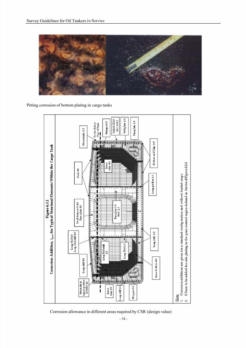
7/21/2019 Survey Guidelines for Tankers
http://slidepdf.com/reader/full/survey-guidelines-for-tankers 37/164
Survey Guidelines for Oil Tankers in Service
- 34 -
Pitting corrosion of bottom plating in cargo tanks
Corrosion allowance in different areas required by CSR (design value)

7/21/2019 Survey Guidelines for Tankers
http://slidepdf.com/reader/full/survey-guidelines-for-tankers 38/164
Survey Guidelines for Oil Tankers in Service
- 35 -
2) Seawater ballast tank: obvious grooving corrosion is easy to occur in vicinity of weld connections
between longitudinals and bulkheads, especially buckling is easy to appear in way of bulkhead plating andlongitudinal by the periodical alternative function of cargo oil and ballast water in adjacent tanks, again,
by the accumulation of water, sludge and rust block, it aggravates the corrosion, such two alternativefactors make the corrosion worse. With the increasing age of the tanker, not only the strength of structural
members, but also the rigidity will be influenced by the corrosion, the buckling and deformation will make
the coating layering and pealing to reduce the corrosion protection so as to form the worst circulation; fortanks often partially ballasted, impacting effect will occur due to shocking in way of level of ballast water,then to aggregate the corrosion; if unclear ballast water is loaded, the lower part of tanks will easy causeacidic materials to damage the coating due to water stoppage, sludge accumulation; vertical girder on
longitudinal bulkhead and cross tie on ring web bear the stronger shearing stress so as to aggregate the
corrosion; the ballast tank in the bow is also to take in consideration of stress corrosion caused by localstress concentration due to impacting of sea wave.3) Cargo oil/arrival ballast tank: Due to the fact that more frequent tank washing is carried out for such
tanks, oil film is damaged, meanwhile, the ballast water left in tanks erodes the horizontal and vertical
level of structural members to cause pitting corrosion, grooving corrosion and scar corrosion. Quickerflow impacting also erodes the edges of structural members, such as inspection hole, cutting of stiffener,edge of stiffener, bracket, etc.
4) Cargo oil/departure ballast tank: Due to the fact that not more frequent tank washing is carried out forsuch tanks, cargo oil left in tanks could protect the structural members slightly, but the ballast water left intanks will cause the pitting corrosion and grooving corrosion in the horizontal and vertical levels ofstructural members.
5) Slop tanks in cargo areas are easy to occur corrosion in way of level of liquid and tank bottom.
Table 4.2 shows the hazardous level of each type of corrosion in various tanks for reference duringinspection.
Table 2.1 Hazardous level of various tanks on oil tankersType of tanks Full-co
ated
protection
Onlycoating
protection onthe upper tank
Coating protection on the
upper and lowertank
Withanode
protection
Withoutany protection
Permanent ballast tank L H+ H+ M-H 1)H++
Cargo oil/arrival ballasttank
Lp H Hp M 2)H+
Cargo oil/departure ballast
tank
Lp M Mp M-L M-H
Cargo oil/heavy ballast
tank
(L) L L X L-H
Cargo tank X L L X L
Explanation:H=high hazard H+= higher hazard X=not considered
M= moderate hazardL=low hazard L-=lower hazard ()=could be negligibleP=pitting corrosion
Remark:
1) Structural members to be given special attention:-horizontal girder -longtidinals and longitudinal bulkhead -longitudinal bulkhead plating-location near the longitudinal bulkhead on the upper edge of web frame
-cross tie -upper part of transverse bulkhead plating2) Area easily subject to pitting corrosion
-level of girder -bottom plating -bottom longitudinals face plating and flanging
3) Other related factors effecting the corrosion hazard-heating of adjacent tank -local coating peal due to poor technology-unreasonable structural design in view of protected coating -local high stress area
-quicker flow area -ejecting area of nozzle for tank washer
2.2 Key points of structural inspection considering of stress influenceThe hull structures will bear the longitudinal bending, static and dynamic loads for both inner liquid andseawater, such loads reflect the low-cycle alternating stress.
Special attention is to be paid to the stress concentration, hard point of structure and hot point areas duringthe structural inspection of oil tankers. Risks will occur because that hull structure defects could not be

7/21/2019 Survey Guidelines for Tankers
http://slidepdf.com/reader/full/survey-guidelines-for-tankers 39/164
Survey Guidelines for Oil Tankers in Service
- 36 -
handled in time due to uncleanness, insufficient lighting, unreachable or illegible cracks because of being
pressured, attention is to be paid. Any doubts, close-up inspection is to be carried out in way of shell plating of light or heavy loading lines, bilge, platform and high stress area where longitudinals penetrate
and connecting bracket, frame toe, etc. a certain number of members are to be sampled for NDT testing,such as PT or MT.
The areas need special attention are to be as followings, for the details, refer to Attachment II – Inspection
for Structural Critical Zones:1) Longitudinal and transverse structures (located in shell plating, deck and bulkhead), web frame and
ends of cross tie, including connecting bracket, especially for the bracket toe end;2) Connection between shall plating, deck, bulkhead longitudinal and web frame, especially for the
inspection of shell plating connection between light and heavy load lines (including the bow area);
3) Inspection for the structural alignment, such as connection of upper and lower longitudinal andtransverse bulkheads in way of inner plating, cross tie in way of bulkhead connection, effectiveextending of longitudinal members in fore and aft locations in cargo tank areas, etc.
4) Opening edges;
5) History information/reference demonstrating the structural critical area, hard point of structure and hot point areas.
In addition to, hull structure will lose its stability by the effect of longitudinal bending stress, lots of HTS
are applied for oil tankers due to the less thickness of plating materials, greater longitudinal span, etc, so itis easy to cause local stability loss. After the panel loses its stability, stress on the same level could notkeep even distribution along the plate width, the stress of partial plating width in way of longitudinalframe beam connection is higher, the stress in middle part of plating width is lower, the hull plating could
not be fully resist the longitudinal bending. When the critical stress of panel XXXXX and corrosion of
members attach a certain degree, the partial structural members included in the longitudinal strength,especially for those plating materials are far away from the natural axis, the critical stress will be reducedgreatly so as to increase the risk of member’s stability loss. The structural members which loss stability
can not meet the Euler Law further, the loading of members will reduce rapidly to 30%~70% of the design
value, then it will cause the extension of structural damage. In addition to, the surface of structuralmembers onboard aged oil tankers will be unsmooth due to wear result by corrosion. The stability of panels are to be calculated by Euler stress, the unevenness of penal surface makes the Euler stress raise a
little than the flat. If the surface unevenness caused by corrosion is 10%, the Euler stress will be raisedabout 3%, if the surface unevenness achieves 25%, the corresponding Euler stress will increase about15%~20%.In general, when the critical stress of plating is determined, the effect to stability due to incompliance with
the Hooke's Law must be taken into consideration, i.e. renewal or proper strengthening is to be carried outunder the instruction of Society as soon as possible.
Through the comparison of similar areas, such as symmetrical locations in port and starboard, inspectionof similar locations of similar tanks and inspection of structures in vicinity in same tanks during the survey,
the reason of defects is to be determined by combining the force analysis and further repairing measures isto be taken.
2.3 Fatigue damage
The fatigue damage will cause cracks, when the crack develops to a certain degree, it will cause suddenstructural failure, therefore, fatigue damage is a defect with great hazard. The fatigue damage occurs in the
form of crack in way of members with great force, the crack occurs in high stress concentration area, andthe damage concentrates in the midship of tanker. The extension rate of fatigue crack under various loads
and the critical length of crack depend on property of steel materials, in the case of stable circular loadingstatus and the initial sharp cutting condition, the time for crack extending to a quiet length exceeds that of
the crack generation.For the moment of visible crack generation, it is found that the ratio of durability of polished specimen and
surface corrosive specimen is within the range of 1.75~2.50 through the testing. Therefore, the corrosivewear of hull structural welds and stress concentration in form of cutting caused in adjacent area of weldswith a quiet length will make the crake generation time shorter, i.e. the obvious reduction of structural
fatigue life. Once the crack forms, i.e. extending till to broke in a stable speed, the extending speed of
subcritical crack is about 10~10.5mm/h. The appearance of stress corrosion reflects that the crack is
vertical to the direction of main pulling stress macroscopically, cracks often have branches, brittle rupturealways occurs in way of fracture, plastic deformation appears microcosmically, it maybe looks like sugar

7/21/2019 Survey Guidelines for Tankers
http://slidepdf.com/reader/full/survey-guidelines-for-tankers 40/164
Survey Guidelines for Oil Tankers in Service
- 37 -
candy, shell pattern, feather, etc.
2.3.1 Areas easily to cause fatigue damage
The structural fatigue damage easily to cause in the following areas:1) Shell plating structure between light and heavy load lines;
2) Connection between deck and deck web frame;
3)
Connection between transverse stool and upper/lower stool seats;4) Connection between bottom slope plating and inner bottom plating.
2.3.2 Effect of HTS to structural fatigue strength
Currently, HTS is widely applied for construction of hull structure in order to reduce the weight of hull,
the mainly applied locations are decks within the range of cargo tanks and deck longitudinal, shear strakeand its attached longitudinals, bilge strake and its longitudinals, top of longitudinal bulkhead, bottom plating and bottom longitudinal, double bottom girder and its longitudinal structural member such as
longitudinal stiffeners, etc. Compared with the general hull structure steel, the widely application of HTS
makes the scantling more smaller, amplification of structural deformation is more greater, and this willincrease the internal stress level to further lead to the increase of possibility of fatigue damage, necessaryverification of toughness reserve at the structural nodes which apply the HTS is to be carried out in order
to ensure the extension rate could be within the foreseeable range once the crack occurs. The oilcompanies prohibit the large amount usage of HTS, where the HTS is used exceeding 30% of the totalsteel materials or above, structural assessment including fatigue analysis is to be carried out by Societywith approval.
Generally, the side structure is more easily damaged due to insufficient fatigue strength, to reduce stress
concentration level is the effective means to control the fatigue damage, during the survey, attention is to be paid to the details of structural nodes, refer to the Attachment III – Typical Damage Cases andRecommended Treatment Requirements.
3. Typical Locations for Structure Inspection
The reliability of strength for hull structures is to be verified by inspection and thickness measurement,currently, the strength criteria mainly includes longitudinal strength and local strength, of which the
longitudinal strength is checked during the special survey through the comparison of ratio between crosssectional area and cross sectional modulus of hull beams in way of main deck (deck and decklongitudinals) and bottom plating (bottom plating and bottom longitudinals) in amidship area with thespecified value in rules. The longitudinal strength criteria of hull beam for oil tankers are to meet all the
requirements of Attachment 2, Chapter 5, PART ONE of CCS Rules.Hull structure also has some rigidity criteria, various deformations of structural members, such as fold,
buckling, dent, etc. will reduce the loading capability of structures.Here introduces defect inspection and analysis for structures in typical areas in order to provide reference
for surveyors and related persons. It shows different defects and recommended treatments in AttachmentIII – Typical Damage Cases and Recommended Treatment Requirements.
3.1 Exposed Deck Area

7/21/2019 Survey Guidelines for Tankers
http://slidepdf.com/reader/full/survey-guidelines-for-tankers 41/164
Survey Guidelines for Oil Tankers in Service
- 38 -
In general, the main deck for oil tankers is in longitudinal frame type to keep the structure continuous
within the cargo areas and being capable of bearing the bending moment and shearing force oflongitudinal strength due to cargo loading or sea conditions. Based on the structural arrangement
characteristics, compared with the other locations, the pull stress or pressure stress of deck is themaximum under the longitudinal bending moment. Meanwhile, it also bears the large loads due to green
water. In addition to, certain parts of main deck will bear the compression stress caused by additional
impacting and attacking in bow under worst weather conditions, it is possible to cause the deck stabilityloss or dilacerations. Currently, most of the decks of oil tankers apply HTS to reduce the scantling ofstructural members and weight and increase the shipbuilding economical efficiency, however, it weakensthe deck rigidity and lead to stability loss.
Corrosion defect is very easily to occur due to the fact that the main deck is influenced by humidity
environment caused by seawater and the cargo vapour, and the sulphur content in cargo oil and heatingeffect to deck by sunlight also quicken the corrosion of steel plate and stiffener. Therefore, crew membersare to clean the slops in such locations frequently, inspection and maintenance working is to be carried out.
Corrosion and crack of the longitudinal members on deck are to be fully noted during the survey,
especially in the butt welds, where leads to fracture with high risk due to improper loading or potentialdefects during construction.
The key points for inspection in deck areas are as followings:
(1)
Obvious pitting corrosion always occurs on the surface of main deck, concentrated pitting corrosionwill finally lead to whole thickness reduction of steel plate, so the effective preventive means is to
periodically carry out rust removal on the surface of corroded steel plates and apply the coating.(2) The other common issue for the main deck is the grooving corrosion, it is to be noted that the
condition of side ballast tank under main deck is worse than that of deck, therefore, the grooving corrosionin way of welds of lower surface of main deck is generally worse than the upper surface.
(3) The deck longitudinal and web beam for oil product tankers are arranged on the upper surface of deck,lots of slops will accumulate in the trunk formed by beam and longitudinal, and this will cause severe
corrosion to deck at the structural roots. For the oil product tankers, in order to be facilitate for tankcleaning, sometimes the deck members are installed on the upper surface of deck plating, because the deck
members stop the slops flow, it will make the water accumulation in the root of members and lead tosevere corrosion.

7/21/2019 Survey Guidelines for Tankers
http://slidepdf.com/reader/full/survey-guidelines-for-tankers 42/164
Survey Guidelines for Oil Tankers in Service
- 39 -
(4) There three common sectional types for sheer strakes onboard the oil tankers, the first is the arc-typed,
oil baffle is provided in the arc; the second is the sheer strake is higher than the main deck, it is to besmooth due to such type sheer bearing the large loads, it is to be capability to effectively pass the stress, if
there is opening or deformation, it will be possible to be fracture or buckling. During the service,sometimes it will be opened or cutting by mistake during repairing, crewmembers are to carry out theinspection in these locations and take measures as early as possible. The third is the deck side plating is
connected with sheer strake in right angles, the upper surfaces of sheer strake and plywood are smooth.
Such type ahs the same requirements of force and maintenance as the second type.(5) In the location where the deck web beam and deck longitudinals connect, in general, concentratedstress will be occur in way of mutational interfaces due to load transmit, at this moment, the stress will
increase suddenly in a minor area and make the weak point cause crack.
(6) Outfitting and fittings of decks, such as bollard, air pipe, vent, base of deck machinery, crane post and penetrating hole of deck piping, etc., except the external corrosion of such equipment, the corrosion and
crack at the roots are to be paid attention.(7) Bulwark and handrail are the means to protect crew members. If the case of a certain deformation,they are not to be regarded as a defect provided that they could still provide such protection. Where the
excessive corrosion or crack occurs on the bulwark bracket or handrail bracket, repair is to be carried outin time, especially such defects occur at the toe end, it will greatly reduce the strength. Under the major
wind and wave loads, stress concentration will occur at the toe ends of bulwark and handrail, therefore,crack on the bulwark root is to be inspected. In addition to, mooring equipment and supporting bracket on
bulwark always rust, rust removal is to be carried out for daily maintenance.
3.2 Cargo areaLocations where longitudinal and transverse structures connect in cargo tanks are the stress concentration
areas due to load transmit. Such areas will occur crack, buckling, etc. due to the function of alternating
loads, therefore, careful inspection is to be carried out to find the defects and eliminate.(1) Lower surface of deck will occur coating peal, especially for the welds in the edge of structuralmembers. For the oil tankers carrying product with high-content sulphur, due to H2S stronger corrosive
property, severe pitting corrosion is easy to occur on the top of cargo tanks, grooving corrosion may occurin heat effect area of welds connecting structural member and deck, the severe grooving corrosion will
lead to the deck crack along the structure or make the deck stability loss, attention is to be paid during thesurvey, and it could be realized by measuring the effective height of fillet welds of deck longitudinal, the
effective height of throat is to be more than 0.8K 0. The node of toe end type for deck web beam has beenoptimized during the construction, and formed a well transition structure, it is to ensure to maintain theoriginal toe end type during the repair. Where the crack damages, repair program is to be determined by
the IACS recommendation of toe end types or through FEM analysis and direct calculation for non-typical
structures.(2) Crack is easy to occur on the stiffeners under deck where fitted with lifting equipment, especially the bracket connecting with deck longitudinal, such case has verified by few oil tankers and attention is to be
paid during the inspection.

7/21/2019 Survey Guidelines for Tankers
http://slidepdf.com/reader/full/survey-guidelines-for-tankers 43/164
Survey Guidelines for Oil Tankers in Service
- 40 -
(3) Where the cutting angle of web and face plating at the end of bracket is less, it will form an abrupt
change of cross-section at the toe and stress concentration will occur and lead to fatigue crack. Meanwhile,there is no necessary supporting at the end web to form an insufficient rigidity of end, then to lead to
repeat deformation and quicken the generation of fatigue crack. The preventive measures includes toincrease the bevel angle of face plating, carry out the second softening treatment for web toe end, increase
the plate thickness and fit tripping bracket, etc.
(4) Where the common bracket is used to connect cross tie and longitudinal, cracks always occur at thecutting of root of cross tie and toe end of bracket due to connecting hard point. The preventive measures isto use arc bracket with free-edge soft toe end to instead of common bracket, both sides of bracket arearranged symmetrically. Buckling will occur on web in the connecting corner between cross tie and
vertical girder due to insufficient plate thickness, preventive measures is generally to change the plate with
local stiffeners.(5) Between the longitudinal bulkhead and inner bottom plating, the toe end of bracket at longitudinal bulkhead is a high stress area. Where the longitudinal of bulkhead is penetrating the vertical girder, cutting
is to be made. The cutting near the bracket toe end is the weakest part of the structure, and crack is easy to
occur at the edge of cutting, attention is to be paid during the daily inspection. The preventive measuresincludes local renewal, increase of new plate thickness, filling the cutting with watertight patching andincrease of structural strength of secondary location.
(6) Triangle bracket is to be used to connect the vertical girder of longitudinal bulkhead with bulkheadlongitudinal on certain level, if the triangle bracket is a common one, crack is easy to cause at the toe enddue to the similar reasons as connecting bracket between cross tie and bulkhead longitudinal. During therepair, soft toe type is to be applied at the bracket toe end, for the detailed specifications, refer to the
requirements in Part 3, Chapter 4 in this Chapter.
(7) In general, the big bracket at the end of horizontal girder of transverse bulkhead is a place wherestress concentrates. For larger oil tankers, more attention is paid for the structural design in such locations.However, due to the improper radio of free-edge arc for the bracket, crack will occur at the bracket toe end
sometimes, attention is to be paid during inspection. The preventive measures include to increase the arm
length of bracket, to fit smaller bracket on the basis of the original one or to use bracket with larger ratio offree-edge arc, to further soften the bracket toe end.(8) Where the horizontal girder of transverse bulkhead is transmitting to a longitudinal bulkhead, a
vertical girder type penetrating longitudinal bulkhead is always used, connecting bracket is to be fitted between the horizontal girder and vertical girder. Sometimes, short girder is fitted at the longitudinal bulkhead end to be as a transmit to the horizontal girder of transverse bulkhead, however, connecting bracket is also fitted between the vertical girder and short girder. Whichever type is selected, the force of
bracket is large and crack is easy to occur.If the damage occurs, the measures include to increase thestrength of bracket, to use bracket with soft toe end, etc. Where there is major difference between
longitudinal girder web and horizontal girder web, the web height of short girder is to be increased, and itis also a good method to maintain the web height of other horizontal girder as the same as that of short
girder.(9) Compared the oil product tankers with crude oil tankers, the major difference are that the longitudinal
and transverse bulkheads isolating the tanks are corrugated bulkheads. Currently, less new-built oil product tankers use such type, and such bulkheads also are required to arrange vertical girders for
strengthening. The convenient tank washing advantage for corrugated bulkhead could not be reflected onthe maximum degree. Cracks sometimes will occur in vicinity of toe ends of bracket of vertical girder for
bulkhead due to stress concentration, therefore, careful inspection is to be carried out during inspection.The measures are to cut the plating with crack firstly, meanwhile, to increase small transmitting bracket as
at the end of original vertical girder.(10) For the oil tankers with smaller tonnage, upper and lower stools are not fitted for the corrugated
bulkhead, the bulkhead is directly connected with inner plating and deck. Cracks have occurred in way ofroot of bulkhead for partial oil tankers, the main reason is there are no strengthened structures under the
side plating, the inner plating in the vicinity of bulkhead root damage by repeated pulling of bulkhead.Therefore, the measures are to provide the corresponding strengthened bracket under the corrugated side plating. For the corrugated bulkhead structure used for oil product tankers, cracks occur on the surface
plate due to the same reason as that mentioned above, the measures are the same, to provide the
corresponding bracket to the corrugated side plating. Due to the larger dimension of the oil tankers, the
stress in such location is relative larger. Therefore, the fillet welds on the surfaces of upper/lower stools,

7/21/2019 Survey Guidelines for Tankers
http://slidepdf.com/reader/full/survey-guidelines-for-tankers 44/164
Survey Guidelines for Oil Tankers in Service
- 41 -
side plating and corrugated bulkhead are used full penetration type, Z-directional steel is to be used for
surface plating of upper/lower stools as far as possible.(11) Due to the fact that both the inner bottom plating and surface plating of lower stool are forced, crack
will occur at the inner plating in the vicinity of root of lower stool. The recommended repairing proceduresare: to renew the steel plate with defects, to change the connecting welds of inner bottom plating, lower
stool side plating and frame corresponding to stool to full penetration type, to add the watertight patching
on the opening of frame.(12) At the bottom of cargo tanks, heating pipe is always arranged, this will cause the temperaturedifference between the tank bottom and adjacent areas and lead to quicken the corrosion in such location,therefore, corrosion of tank bottom structure is always to be noted, where necessary, thickness
measurement is to be taken. Suction/groove is easy to occur pitting crack due to effect of water flow, the
measures include bead welding or plate renewal, if necessary, proper thickening is to be carried out.(13) Pressure test is to be carried out for the butterfly valve on the bottom of single hull oil tankers inorder to confirm if it leaks.
3.3 Bilge areaThe inclined plating at bilge is the primary composition of hull girder, it is to be included in longitudinalstrength calculation, which is a supporting structure for inner bottom plating and side inner shell plating.
The intersect location where inclined plating of double hull oil tankers and inner bottom plating is alsosubject to major fatigue stress besides the corrosion, the center lines of bilge inclined plating, inner bottom plating and bottom side girder are intersected at one point. If there is a large error, stress concentration willoccur, and the same issue will apply to three plates (nodes) at the top of inclined plating.
(1) Due to the fact that the lower end of inner bottom plating is subject to larger stress, crack will always
occur in the vicinity of opening of web frame. The repairing method is to renew the damaged plate, thenthe opening is covered by semi-watertight patching.(2) The inner bottom plating will be dilacerated due to stress concentration and fatigue at lower end of
inclined plating. The measures are to change the damaged steel plate to Z-directional steel, and change the
fillet weld to full penetration type and ensure that the central lines of three plates intersects at one point.
(3) As the same as above-mentioned, due to the stress concentration and fatigue, crack occurs at the
cutting of transverse structure in the vicinity of ends of inclined bottom. The measures are to cover thecutting by watertight patching, to connect the web frame stiffener and bracket with soft toe.
3.4 Side structureSide structure is the primary composition of hull. The structural corrosion is the important defect type for

7/21/2019 Survey Guidelines for Tankers
http://slidepdf.com/reader/full/survey-guidelines-for-tankers 45/164
Survey Guidelines for Oil Tankers in Service
- 42 -
side structures, especially at the top of side, due to the fact that most of time the structure is not immersed
in the ballast water, the corrosion of top structure will be worse. The corrosion of side structures andtransverse bulkheads mainly reflect on the level of various structural members, such as web and face plate
of longitudinal, butt welds, lightening hole and drain hole and thickness transmit zone are to be noted.On the side of stiffeners fitting for side plating and transverse bulkhead, cracks are easy to occur in way of
intersection locations for various members, and such cracks are easy to spread due to function of
periodical loads inside or outside tanks, and it has certain hazard. Cracks always occur on theunsymmetrical members, such as L-shaped section bar, bracket toe end and bulkhead member in way of penetration. For large oil tankers, fatigue crack in way of connecting location of longitudinal andtransverse structures in sides above light load line is also defects which always occur, in general, crack
occurs in way of intersection between horizontal girder of transverse bulkhead and longitudinal bulkhead,
and cutting of penetrating vertical stiffener for horizontal girder of transverse bulkhead.(1) Bracket between side longitudinal of side structure and web frame is very important, and the force islarge, especially in the vicinity of heavy load line, crack damage possibly occurs. The measures are to
increase the bracket between stiffener ends, to optimize toe end type, meanwhile, to fit connecting bracket
with soft toe at the other side of web frame.(2) The web frame near the bilge at sides is subject to larger force, which is a key location to transmitloads between sides and double bottom. In order to meet the needs of ballast tank structure inspection, it
must make a lightening hole in this location on web frame, therefore, buckling will occur sometimes in thevicinity of lightening hole. The better method is to fit stiffeners around the lightening hole.(3) The horizontal girder in the vicinity of transverse bulkhead at sides is the locations bearing largerforce, and is a key location to transmit loads between sides and transverse bulkhead. In order to meet the
needs of ballast tank structure inspection, it must make a lightening hole in this location on horizontal
girder at sides, therefore, buckling will occur sometimes in the vicinity of lightening hole. The bettermethod is to fit stiffeners around the lightening hole.
3.5 Bottom structure
The bottom structure is also an important part, it is included in the longitudinal strength calculation, and provides supporting and protection for the cargo tanks. The corrosion of bottom structure is an importantdefect type, the bottom structures of oil tankers are to be regarded as key inspection area, for the tanks
with coating protection, the main corrosion type is pit and scar corrosions; for coating mainly containingof Inorganic zinc, the corrosion type is generally in blocky, the thickness loss is not great, for the epoxycoating, the corrosive pit always appears in deep circular. For tanks without any coating protection, thecorrosion is always very common, mainly concentrates at the cutting of web frame, lightening hole of
longitudinal or water outlet, etc. The trimming design will make the water accumulation at the after part oftanks, and the corresponding drainage device is difficult to discharge all the water, therefore, full attention
is to be paid to the bottom plating at the after part of each tanks during the inspection. For the oil tankerswith heating system in cargo tanks, inner bottom and its structural member will quicken the corrosion rate
due to heat influence of tanks, and grooving corrosion always occurs at the root of longitudinal.(1) During the load transmit between transverse bulkhead and bottom structure, if the structural transmit
is insufficient, it is easy to occur stress concentration in way of longitudinals of inner bottom, and this willlead to crack at the toe end structure between inner bottom longitudinal and floor frame. The measures are
change the vicinity bracket to transmitting bracket with soft toe, and the same bracket with soft toe is fittedat the other side of floor frame.
(2) The bottom girder in the vicinity of transverse bulkhead at bottom is a location to bear large force,and is a key location to transmit loads between transverse bulkhead and double bottom. In order to meet
the needs of ballast tank structure inspection, it must make a lightening hole in this location on bottomgirder, therefore, buckling will occur sometimes in the vicinity of lightening hole. The better method is to
fit stiffeners around the lightening hole.(3) During the load transmit between longitudinal bulkhead and bottom structure, the bracket at the ends
of vertical girder is the key location to transmit load, where bear large force, cracks will occur when thestress of penetrating hole of longitudinals at floor frame is large. In order to solve this problem, in general,watertight patching is to be provided for the penetrating hole in the vicinity of bracket toe end. And
watertight patching is also to be provided for the penetrating hole near the lightening hole.
(4) Cut through is easy to occur due to the fact that the shell plating at lower part of sounding pipe is
always impacted, attention is to be paid during the inspection.

7/21/2019 Survey Guidelines for Tankers
http://slidepdf.com/reader/full/survey-guidelines-for-tankers 46/164
Survey Guidelines for Oil Tankers in Service
- 43 -
(5) Due to the flow function at the lower part of suction, it is easy to corrode, during the inspection, the
suction is to be removed, if it is not facilitate, it is to be inspected by manual or by thickness measurement.
3.6 Bow areaThe bow area is directly affected by liquid shacking and wave impacting loads, for the oil tankers with
larger curvature of stem post, such effect is especially obvious.
(1) Corrosion is easy to occur at the foundation of anchor gear, base of out-fittings, such as vent,ventilating pipe, etc. on the bow deck;(2) Buckling at the lower bracket of side frame at forecastle;(3) Depressed deformation is easy to occur at the connection between bow platform plating and shell
plating, especially in the larger linear change areas. It is to be noted to inspect the corrosion caused by
abrupt change of cross-section in way of platform plating and chain locker;(4) Penetrating holes of longitudinals of inner or outer plating in forepeak tanks and large stiffened brackets are easy to occur cracks, attention is to be paid during the inspection.
3.7 Engine room areaThe main inspection areas of engine room are as follows:(1) Shell plating at bilge. Especially for the area under pumps, local corrosion is easy to occur in the shell
plating due to the effect of oil and water drip.(2) Shell plating under the foundation of main engine. Some oil tankers have occurred local penetrativecorrosion with the characteristics is that the thickness of plating is good, holes with diameter about 10mmappear in the middle. Such defects have occurred for few times for the aged oil tankers, especially for the
tankers arranged to voyage repair or repair by the shipping companies.
(3) Severe corrosion, even rotten wear at the web root in vicinity of floor at shell plating frame before orafter the foundation of main engine.(4) Where ballast tank is provided at port or starboard of engine room, due to the fact the longitudinal or
transverse bulkhead in ballast tank near the engine room, the temperature difference cause the bulkhead
and its stiffeners to corrode quickly, in general, the corrosion occurs in the ballast tanks, attention is to be paid during the inspection.(5) There are more overboard discharges in the engine room area, corrosion and crack will occur at the
shell plating of overboard discharge and its side tubes, attention is to be paid.
3.8 Stern areaDue to the effects of vibration, cavitation, impacting, etc. in the stern area, the shell plating is easy to occur
cavitation corrosion, homogeneous corrosion, etc.
3.9 Pump roomThe following areas in pump room are to be noted during inspection:
(1) Locations in vicinity of shell plating at the ends of fore bulkhead of pump room is possibly to occurcracks and local deformation due to wave beating, robbing at sea, etc.;
(2) Structures within 1/3 moulded height of fore and aft bulkheads in pump room occur severe corrosiondue to temperature difference;
(3) Foundations of various pumps in pump room;(4) Corrosion at the end of boundary between fuel oil tank and pump room;
(5) Attention is to be paid during inspection if there is no doubling plate/thickened plate provided at thelower structure of swash opening of SLOP scavenge pipe.
(6) The suction inlet of sea chest valve and the valve body on the attached tubes are to be inspected forleakage (in general, the compressed air pipe is provided on the attached tube, it could be verified by
inspecting the compressed air pressure or whether the overboard is bubbling) .
SECTION 2 COATING PROTECTION
Corrosion is one of the important factors that cause structural damage. In recent years, IMO, IACS and theindustry were paid more and more attention about the corrosion of structure. IACS issued the REC.87 as
early as June 2004- “Guidelines for Coating Maintenance & Repairs for Ballast tanks and CombinedCargo/Ballast tanks on Oil Tankers”, IMO adopted “Performance Standard for Protective Coatings for

7/21/2019 Survey Guidelines for Tankers
http://slidepdf.com/reader/full/survey-guidelines-for-tankers 47/164
Survey Guidelines for Oil Tankers in Service
- 44 -
Dedicated Seawater Ballast Tanks in All Types of Ships and Double-Side Skin Spaces of Bulk Carriers”
(MSC.215(82), hereinafter as PSPC) on December 8, 2006. In order to implement PSPC in advance forship applied with the common rules, IACS adopted PR34-“Procedural Requirement on Application of the
IMO Performance Standard for Protective Coatings (PSPC), Resolution MSC.215(82), under IACSCommon Structural Rules for Bulk Carriers and Oil Tankers”.
1.
Requirements Raised by SOLAS Convention and Societies
(1) SOLASⅡ-1/3-2: For Oil tanker which the building contract is placed on or after 1 July 2008 and not
less than 500 gross tonnage, all dedicated seawater ballast tanks shall have an efficient corrosion prevention system, such as hard protective coatings or equivalent. The coatings should preferably be of a
light color. The scheme for the selection, application and maintenance of the system shall be approved by
the Administration, based on “Guidelines for The Selection, Application and Maintenance of CorrosionPrevention Systems of Dedicated Seawater Ballast Tanks” adopted by A.798(19) , sacrificial anodes shallalso be used.
(2) IACS PR34: For the oil tanker constructed under IACS Common Structural Rules (150 m in lengthand upwards), contracted on December 8,2006 or later but before applicable date of Reg. SOLASⅡ-1/3-2
adopted by MSC.216(82) (Date mentioned at below No.3), all dedicated seawater ballast tanks shallcomply with PSPC.
(3) SOLASⅡ-1/3-2.1 apply to ships of not less than 500 gross tonnage and: 1. for which the buildingcontract is placed on or after 1 July 2008; or 2.in the absence of a building contract, the keels of which are
laid or which are at a similar stage of construction on or after 1 January 2009; or 3. the delivery of whichis on or after 1 July 2012. all dedicated seawater ballast tanks shall comply with PSPC.
2. Type of Coating
In accordance with its protective performance, coating is divided to following type:Hard coating is a coating which chemically converts during its curing process, normally used for new
constructions or non-convertible air drying coating which may be used for maintenance purposes. Hardcoating can be either inorganic or organic.
The most common hard coating is base line of the epoxy resin. If proved by the relevant tests and obtainedan equivalent protective effect, other paint can also be defined as a hard coating. The standard of
environment and process required by hard coating is very high, and the adhesion strength is usually notless than 3MPa.
Hard coating required by PSPC Code should be epoxy coating system. the performance of other coatingsystems should pass the test procedure stated in PSPC Annex 1. The multi-coat systems is proposed, each
layer coating is different color. Surface coating should be light-colored, in order to be easy to check duringservice life.Semi-hard coatings: are coatings that, after drying, remain flexible and hard enough to be touched and
walked upon without damaging them and that are not affected by water erosion during de-ballasting
operations.Soft coatings: are coatings that do not dry, but remain permanently soft. Soft coatings are notrecommended. Where Soft Coatings have been applied, safe access is to be provided for the surveyor to
verify the effectiveness of the coating and to carry out an assessment of the conditions of internal
structures which may include spot removal of the coating
3. Coating Condition Assessment
GOOD: Condition with spot rusting on less than 3% of the area under consideration without visible failureof the coating. Rusting at edges or welds, must be on less than 20 % of edges or weld lines in the area
under consideration.FAIR: Condition with breakdown of coating or rust penetration on less than 20 % of the area under
consideration. Hard rust scale rust penetration must be less than 10 % of the area under consideration.Rusting at edges or welds must be on less than 50 % of edges or weld lines in the area under
consideration.POOR: Condition with breakdown of coating or rust penetration on more than 20% or hard rust scale on
more than 10% of the area under consideration or local breakdown concentrated at edges or welds on morethan 50 % of edges or weld lines in the area under consideration.

7/21/2019 Survey Guidelines for Tankers
http://slidepdf.com/reader/full/survey-guidelines-for-tankers 48/164
Survey Guidelines for Oil Tankers in Service
- 45 -
Means of Coating Evaluated:Recognizing that different areas in the tank experience different coating breakdown and corrosion patterns,the intent is to subdivide the planar boundaries of the tank for evaluation of coating, into areas small
enough to be readily examined and evaluated by the Surveyor. Each area is then rated (GOOD, FAIR or
POOR) and the tank rating is then to be not higher than the rating of its “area under consideration” having
the lowest rating. Special attention should be given to coating in Critical Structural Areas, Each CriticalStructural Area is rated (GOOD, FAIR or POOR) and the rating of each “area under consideration” is then
to be not higher than the rating of its Critical Structural Area (if present) having the lowest rating.
The “area under consideration” with the poorest coating condition will determine whether examination of ballast tanks is required at subsequent Annual Surveys. Hence, it is not intended to “average” the coatingcondition for all “areas under consideration” within a tank, to determine an “average” coating condition
for the entire tank.Definitions of “areas under consideration” are as follows:
Single Hull Tanker - Wing Ballast Tanks:
Deck and bottom
Areas of deck and bottom plating with attached structure (one (1) area to consider for deck and one (1)area to consider for bottom).
Side shell and longitudinal bulkheads
Areas of side shell and longitudinal bulkheads with attached structure, in lower, middle and upper third
(three (3) areas to consider for side shell and three (3) areas to consider for longitudinal bulkhead).
Transverse bulkheads (forward and aft)
Areas of transverse bulkhead and attached stiffeners, in lower, middle and upper third (three (3) areas toconsider for forward transverse bulkhead and three (3) areas to consider for aft transverse bulkhead).
Double Hull Tanker
Double bottom ballast tank:Areas of tank boundaries and attached structure, in lower and upper half of tank (two (2) areas to
consider).
Double hull side tank:Deck and bottomAreas of deck and bottom plating with attached structure (one (1) area to consider for deck and one (1)
area to consider for bottom).Side shell and longitudinal bulkheadsAreas of side shell and longitudinal bulkheads with attached structure, in lower, middle and upper third(three (3) areas to consider for side shell and three (3) areas to consider for longitudinal bulkhead).
Transverse bulkheads (forward and aft)
Areas of transverse bulkhead and attached stiffeners, in lower, middle and upper third (three (3) areas toconsider for forward transverse bulkhead and three (3) areas to consider for aft transverse bulkhead). Note: For the L-side tanks, should be considered separately as sides and double bottom tanks.
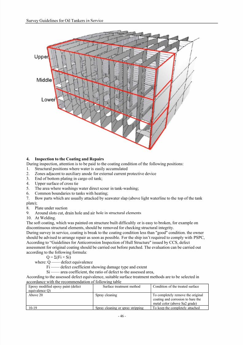
7/21/2019 Survey Guidelines for Tankers
http://slidepdf.com/reader/full/survey-guidelines-for-tankers 49/164
Survey Guidelines for Oil Tankers in Service
- 46 -
4. Inspection to the Coating and Repairs
During inspection, attention is to be paid to the coating condition of the following positions:1. Structural positions where water is easily accumulated
2. Zones adjacent to auxiliary anode for external current protective device3. End of bottom plating in cargo oil tank;
4.
Upper surface of cross tie5. The area where washings water direct scour in tank-washing;
6. Common boundaries to tanks with heating;7. Bow parts which are usually attacked by seawater slap (above light waterline to the top of the tank
plate);8. Plate under suction
9. Around slots cut, drain hole and air hole in structural elements10. At Welding.
The soft coating, which was painted on structure built difficultly or is easy to broken, for example ondiscontinuous structural elements, should be removed for checking structural integrity.
During survey in service, coating is break to the coating condition less than "good" condition. the ownershould be advised to arrange repair as soon as possible. For the ship isn’t required to comply with PSPC,
According to “Guidelines for Anticorrosion Inspection of Hull Structure" issued by CCS, defectassessment for original coating should be carried out before patched. The evaluation can be carried out
according to the following formula:Q = Σ(Fi × Si)
where: Q —— defect equivalenceFi —— defect coefficient showing damage type and extent
Si —— area coefficient, the ratio of defect to the assessed area,According to the assessed defect equivalence, suitable surface treatment methods are to be selected in
accordance with the recommendation of following tableEpoxy modified epoxy paint (defectequivalence Q)
Surface treatment method Condition of the treated surface
Above 20 Spray cleaning To completely remove the original
coating and corrosion to bare the
metal color (above Sa2 grade)10-19 Spray cleaning or spray stripping To keep the completely attached

7/21/2019 Survey Guidelines for Tankers
http://slidepdf.com/reader/full/survey-guidelines-for-tankers 50/164
Survey Guidelines for Oil Tankers in Service
- 47 -
original coating, and completely
remove the corrosion and unsecuredattached original coating (Sa2grade)
5-9 Spray stripping or power toolgrinding
To keep the completely attachedoriginal coating, and completelyremove the corrosion and unsecured
attached original coating (St3 gradeor Sa2 grade)
4 and below 4 Power tool grinding To remove the corrosion andunsecured attached original coatingand keep the others (St2-3 grade)
Defect coefficient Fi
Area coefficient Si
For ship complied with PSPC, coating repair shall comply with the IMO "Guidelines for coatingmaintenance and repair". The informations of maintenance, repair and partial re-coating are to be
recorded in the Coating Technical File.In case of coating condition of tank is less than "good", and the owner will not repair or restore to the
"good" condition, then internal inspection for the tanks is to be carry out and thickness measurements asnecessary in annual survey.
SECTION 3 SAFE ACCESS OF OIL TANKERS
For the purpose of crew safety and enhancement of structure survey, IMO has adopted several resolutions
to give detailed requirements for structural access of oil takers.
1 Safe access to bow
Oil tankers constructed on or after 1 July 1998 are to be provided with means to enable the crew to gain
safe access to the bow even in severe weather conditions. The arrangement of safe access is to beapproved in accordance with Resolution MSC.62(67) Guidelines for Safe Access to Tanker Bows.
Detailed technical specifications include following points:For tankers constructed on or after 1 July 1998, the access is to be by means of either a walkway on the
deck or a permanently constructed gangway of substantial strength at or above the level of the
superstructure deck or the first tier of a deckhouse which is to:(1) be not less than 1 m in width, situated on or as near as practicable to the centre line of the ship and

7/21/2019 Survey Guidelines for Tankers
http://slidepdf.com/reader/full/survey-guidelines-for-tankers 51/164
Survey Guidelines for Oil Tankers in Service
- 48 -
located so as not to hinder easy access across working areas of the deck;
(2) be fitted at each side throughout its length with a footstop and guard rails supported by stanchions.Such rails are to consist of no less than 3 courses, the lowest being not more than 230 mm and the
uppermost being at least 1 m above the gangway or walkway, and no intermediate opening is to be morethan 380mm in height. Stanchions are to be at intervals of not more than 1.5 m;
(3) be constructed of fire resistant and non-slip material;
(4) have openings, with ladders where appropriate, to and from the deck. Openings are not to be morethan 40 m apart;(5) if the length of exposed deck to be traversed exceeds 70 m, have shelters of substantial constructionset in way of the gangways or walkways at intervals not exceeding 45 m. Every such shelter is to be
capable of accommodating at least one person and be so constructed as to afford weather protection on the
forward, port and starboard sides; and(6) if obstructed by pipes or other fittings of a permanent nature, be provided with means of passage oversuch obstruction.
Alternative or modified arrangements for tankers with space constraint are acceptable, provided
that such alternative or modified arrangements achieve an equivalent level of safety for access tothe bow. Arrangements already approved for the tankers constructed before 1 July 1998 may be accepted, provided
that such existing arrangements achieve an equivalent level of safely for access to the bow. For oil tankerswith length 100m or below, arrangements of access width not less than 600mm are acceptable, and inaddition, other requirements are the same as those in above 1.
2 Hull structural access
According to the requirements of SOLAS Convention, for oil tankers constructed on or after 1 October
1994, safe access to cofferdams, ballast tanks, cargo tanks and other spaces in the cargoarea is to be direct from the open deck and such as to ensure their complete inspection. If access
to double bottom spaces is from cargo pump room, pump-room, deep cofferdam, pipe tunnel or similarcompartments, proper ventilation is to be considered. For access through horizontal openings, hatches ormanholes, the dimensions are to facilitate the hoisting of an injured person from the bottom of the space.
The minimum effective opening is not to be less than 600 mm x 600 mm.
For access through vertical openings or manholes providing passage through the length and breadth of thespace, the minimum effective opening is to be not less than 600 mm x 800 mm at a height of not morethan 600 mm from the bottom shell plating unless gratings or other foot holds are provided.
For oil tankers of less than 5,000 tonnes deadweight, the Administration may approve smaller dimensions
for the openings, if the ability to traverse such openings or to remove an injured person can be proved tothe satisfaction of the Administration.Oil tankers of 500 gross tonnage and over constructed on or after 1 January 2005, safe access to cargo
holds, cofferdams, ballast tanks, cargo tanks and other spaces in the cargo area is to be direct from the
open deck and such as to ensure their complete inspection. Safe access to double bottom spaces may befrom a pump-room, deep cofferdam, pipe tunnel, cargo hold, double hull space or similar compartment notintended for the carriage of oil or hazardous cargoes.
Tanks and subdivisions of tanks having a length of 35 m or more are to be fitted with at least two access
hatchways and ladders, as far apart as practicable. Tanks less than 35 m in length are to beserved by at least one access hatchway and ladder. When a tank is subdivided by one or more swash bulkheads or similar obstructions which do not allow ready means of access to the other parts of the tank,
at least two hatchways and ladders are to be fitted.
Each cargo hold is to be provided with at least two means of access as far apart as practicable. In general,these accesses are to be arranged diagonally, for example one access near the forward bulkhead on the port side, the other one near the aft bulkhead on the starboard side.
Each space is to be provided with means of access to enable, throughout the life of a ship, overall andclose-up inspections and thickness measurements of the ship’s structures to be carried out by the
Administration, the company, and the ship’s personnel and others as necessary. Where a permanent meansof access may be susceptible to damage during normal cargo loading and unloading operations or where it
is impracticable to fit permanent means of access, the Administration may allow, in lieu thereof, the
provision of movable or portable means of access, as specified in the Technical provisions, provided thatthe means of attaching, rigging, suspending or supporting the portable means of access forms a permanent part of the ship’s structure. All portable equipment is to be capable of being readily erected or deployed by

7/21/2019 Survey Guidelines for Tankers
http://slidepdf.com/reader/full/survey-guidelines-for-tankers 52/164
Survey Guidelines for Oil Tankers in Service
- 49 -
ship’s personnel. The construction and materials of all means of access and their attachment to the ship’s
structure are to be to the satisfaction of the Administration.A ship’s means of access to carry out overall and close-up inspections and thickness measurements are to
be described in a Ship Structure Access Manual approved by the Administration, an updated copy ofwhich is to be kept on board. The Ship Structure Access Manual is to include the following for each space:
.1 plans showing the means of access to the space, with appropriate technical specifications
and dimensions;.2 plans showing the means of access within each space to enable an overall inspection to be carried out,with appropriate technical specifications and dimensions. The plans are to indicate from where each areain the space can be inspected;
.3 plans showing the means of access within the space to enable close-up inspections to be
carried out, with appropriate technical specifications and dimensions. The plans are to indicate the positions of critical structural areas, whether the means of access is permanent or portable and from whereeach area can be inspected;
.4 instructions for inspecting and maintaining the structural strength of all means of access
and means of attachment, taking into account any corrosive atmosphere that may be within the space;.5 instructions for safety guidance when rafting is used for close-up inspections and thicknessmeasurements;
.6 instructions for the rigging and use of any portable means of access in a safe manner;
.7 an inventory of all portable means of access; and
.8 records of periodical inspections and maintenance of the ship’s means of access.Requirements for dimensions of openings of hull structural access
For access through horizontal openings, hatches or manholes, the dimensions are to be sufficient to allow a person wearing a self-contained air-breathing apparatus and protective equipment to ascend or descendany ladder without obstruction and also provide a clear opening to facilitate the
hoisting of an injured person from the bottom of the space. The minimum clear opening is not to be less
than 600 mm x 600 mm. When access to a cargo hold is arranged through the cargo hatch, the top of theladder is to be placed as close as possible to the hatch coaming. Access hatch coamings having a heightgreater than 900 mm are also to have steps on the outside in conjunction with the ladder.
For access through vertical openings, or manholes, in swash bulkheads, floors, girders and web frames
providing passage through the length and breadth of the space, the minimum opening is to be not less than600 mm x 800 mm at a height of not more than 600 mm from the bottom shell plating unless gratings orother foot holds are provided. Openings of 600 mm x 800 mm may include round angles with radius of
300mm. For girders and floors in double bottom, if large opening is not good for structural strength,
openings of 600 mm x 800 mm (height x width) may be adopted.In order to facilitate rescue of the injured person with stretcher, in addition to traditional 600 mm x 800 mmopenings with angular radius of 300mm, vertical opening of 850mm x 620mm can be adopted , with width ofupper half part exceeding 600mm, width of lower half part less than 600mm and total height not less than850mm.
For oil tankers of less than 5,000 tonnes deadweight, smaller dimensions for the openings may be accepted,if the ability to traverse such openings or to remove an injured person can be proved.Requirements for hull structural access of oil tankers:
Cargo oil tanks and water ballast tanks, except
those specified in the right column
Wing water ballast tanks of less than 5 m width
forming double side spaces and their bilge hoppersections
Access to the structure below deck and vertical structure
For tanks of which the height is 6 m and over,
containing internal structures, permanent means ofaccess are to be provided in accordance with .1 to .6:.1 continuous athwartship permanent access arranged
at the transverse bulkheads, at a minimum of 1.6 m to amaximum of 3m below the deck top;.2 at least one longitudinal permanent means of
access, one at a minimum of 1.6 m to a maximum of 6m below the deck top, another at a minimum of 1.6 m
to a maximum of 3 m below the deck top;.3 access between the arrangements specified in .1
and .2 and from the main deck to either .1 or .2;.4 Continuous longitudinal permanent access is to beon structure of longitudinal bulkhead at stiffener side,
2.1 For double hull spaces above the upper knuckle point of
bilge hopper section, permanent means of access are to be provided according to following .1 to .3:.1 if vertical distance between horizontal uppermost platform
and deck is 6m and above, continuous longitudinal permanentmeans of access are to be provided within full tank length, anda means of access is allowed to pass through transverse web at
1.6~3m below deck, and vertical ladder is to be provided at both sides of the tank;
.2 Vertical distance between continuous longitudinal permanent means of access on the structure is not to be more
than 6m; and.3 The platform is to be connected with horizontal girder oftransverse bulkhead as far as possible.

7/21/2019 Survey Guidelines for Tankers
http://slidepdf.com/reader/full/survey-guidelines-for-tankers 53/164
Survey Guidelines for Oil Tankers in Service
- 50 -
and connected with horizontal girder of transverse
bulkhead when possible, and there is access fromcontinuous longitudinal permanent access to transverseweb, unless permanent means are provided at highest
platform to facilitate inspection at middle height withreplaceable equipment defined in 3.9 of technical
provisions;
.5 For ships with supports not less than 6m above bottom, transverse permanent means of access are to be provided on the support to facilitate inspection of big
brackets at both sides of the tank, and the transverse permanent means of access can connect with alongitudinal permanent means of access specified
in .4;and.6 For small ship of which the height is less than 17m,replaceable equipment defined in 3.9 of technical
provisions can be connected to means of accessspecified in .4 as replaceable measure.For structure as part of means of access, the
Administration gives tolerance of 10%
1.2 For tanks of which the height is less than 6 m,
replaceable equipment defined in 3.9 of technical provisions or portable means may be utilized in lieu ofthe permanent means of access.
2.2 For bilge section with vertical distance of 6m and above
from bottom to upper knuckle point, a longitudinal permanentmeans of access is to be provided within full tank length.Vertical permanent means of access is to be provided at both
side of tank.2.2.1 Longitudinal continuous permanent means of access are
to be provided at 1.6~3m below top of bilge tank. Under suchcondition, the extension platform at web on longitudinal
permanent means of access may be used as means of access forinspecting structural hazardous area.
2.2.2 Same plan may be adopted. Longitudinal continuous permanent means of access are to be located at 1.2m below ringribs, and portable means of access is allowed for entering
hazardous area.
Forepeak tank
1.3 For forepeak tank at centerline of collision bulkhead with tank depth more than 6m, suitable meansof access shall be provided to reach hazardous area
such as structure below deck, platform, collision bulkhead and hull structure.1.3.1 For platform with vertical height less than 6m
from deck top, considering condition of using portablemeans of access, suitable means of access are to be
provided.1.3.2 If the distance between deck top and platform,distance between platforms or distance between lowest
platform and bottom are 6m and above, replaceableequipment defined in 3.9 of technical provisions can be
used.
2.3 Where the vertical distance referred to in 2.2 is
less than 6 m, portable means of access defined in 3.9 oftechnical provisions may be utilized in lieu of the permanentmeans of access. To facilitate the operation of the portable
means of access, in-line openings in horizontal stringers are to be provided. The openings are to be of an adequate diameterand are to have suitable protective railings.
Note: 3.9 of technical provisions means paragraph 3.9 of Resolution MSC.133(76) Technical Provisions for Means ofAccess for Inspections.
During survey to oil tankers in service, considering that hull structural accesses will deteriorate due to
corrosion for a long time, ship motion force and liquid sloshing in the tank, the surveyors are to examine
access prior to entering compartment/space to confirm that access is in good working condition. Survey procedures are as follows:1 Inspection of all accesses of the tanker is to be recorded according to requirements of ship’s safety
management system. The surveyors are to consult these records prior to inspecting permanent access.
Access manual is attached with record form and the updated record of inspected access part is to include atleast inspection date, inspector name and post, signature for confirmation, inspected access part,confirmation of service condition or any deterioration or substantial damage found. The issued license
must be kept for check.
2 It is to inspect access carefully. If damage, corrosion or deterioration is found, it is to evaluate
whether damage or deterioration will affect safety of access. The deterioration that will affect safety ofaccess is called substantial damage, and measures are to be taken to ensure that affected parts will not be

7/21/2019 Survey Guidelines for Tankers
http://slidepdf.com/reader/full/survey-guidelines-for-tankers 54/164
Survey Guidelines for Oil Tankers in Service
- 51 -
used until proper repair is carried out.
For survey of movable means of access, refer to annex of IACS UI SC191 “Guidelines forApproval/Acceptance of Alternative Means of Access”.Alternative means of access (including movable and portable) generally include but are not limited to followingequipment:a) hydraulic arm (vehicle lift platform);
b) wire lift platform;c) portable platform;d) scaffold;e) raft;
f) portable ladder (portable ladders more than 5 m long may only be utilized if fitted with a mechanicaldevice to secure the upper end of the ladder ); g) other means of access approved by the Administration.Methods for safe application of alternative means of access and methods for installing such means of access areto be clearly stated in the Manual of Ship Structural Access. The surveyors are to check not only periodicinspection and maintenance record of portable means of access but also periodic inspection and maintenance
record of movable means of access provided by the shore-based manufacturer. If problems are found, theequipment may be refused to use.
SECTION 4 REPAIRS OF HULL
1 Principles
Ship repair is generally carried out according to the principles of resuming. If it is found that parts ofstructure damage repeatedly, modification of node type of structure or increase of structural dimension
may be considered. Modification of node type of main structure is to be approved by CCS Plan ApprovalCenter. General principles for hull repair are as follows:
1) principle of resuming;2) steel plate section and welding consumables for hull repair are to comply with relevant requirements
of CCS Rules for Materials and Welding. The shipyard is to submit material qualification certificate andthe grade of material is not to be lower than that of raw material;
3) the construction technology of hull repair is to be approved;
4) repair of each kind of structure is to avoid weld at stress concentration, the spacing of parallel buttweld of hull structure is to be not less than 100mm, and sharp angle intersection is to be avoided. The parallel distance between butt welds and fillet welds is not to be less than 50mm;
5) hull plate butt welds are to be double-side welded with bevel or one-side welded with back formationto ensure full thickness penetration. On completion of construction, X ray examination or ultrasonic
examination is to be carried out to ensure weld quality. The weld type of such members as frame, stiffenerand bracket are to be same as former weld type;
6) It is not allowed to remove or move hull strength member or establish temporary opening on mainstrength members such as strength deck, side shell plating and watertight bulkhead;
7) after repair, hull watertight structure is to be subject to tightness test;8) in general, repair of compensating plate of main hull structure is not acceptable and is only used in
emergency to allow ship to reach appropriate port for permanent repair.
Pitting corrosion and groove corrosion are popular in oil tanker structure and the handling is important. Inactual application, the assessment of pitting corrosion is to follow following principles:1) the reference area of pitting corrosion is single panel area, with diameter less than 150mm;
2) for section or bracket, if pitting corrosion density is more than 20%, even corrosion criteria is to beadopted. For pitting corrosion of panel with density less than 20%, minimum residual thickness of 75%construction thickness is acceptable and plate thickness at any point is not to be less than 6mm;
3) for plates as primary members, if pitting corrosion density is more than 20%, even corrosion criteria is
to be adopted. For pitting corrosion of panel with density less than 20%, minimum residual thickness of 70%construction thickness is acceptable;4) acceptable standards for groove corrosion are to meet the requirements of pitting corrosion as well as
requirements of groove width not more than 30mm;5) for area with only coating bubbling, corrosion will not occur inside and only random check is needed;
6) for primary members designed and constructed according to common rules, if pitting corrosiondensity is more than 20%, even corrosion criteria is to be adopted. For pitting corrosion of panel with
density less than 20%, minimum residual thickness of 75% design thickness is acceptable and plate

7/21/2019 Survey Guidelines for Tankers
http://slidepdf.com/reader/full/survey-guidelines-for-tankers 55/164
Survey Guidelines for Oil Tankers in Service
- 52 -
thickness at any point is not to be less than 6mm and tren-0.5mm;
7) for plates of oil tanker designed and constructed according to common rules, if pitting corrosiondensity is more than 20%, even corrosion criteria is to be adopted. For pitting corrosion of panel with
density less than 20%, minimum residual thickness of 70% design thickness is acceptable and platethickness at any point is not to be less than 6mm and tren-1mm.During survey, if local pitting corrosion and groove corrosion are found, corresponding handling is to be
carried out even though corrosion is within limit. Detailed requirements are as follows:1) for pitting corrosion/groove corrosion within corrosion limit, local derusting is to be arranged andcoating is to be reapplied;2) if pitting corrosion exceeds corrosion limit but residual thickness is more than 6mm, deposit repair is
allowed. For high strength steel, input energy is to be controlled strictly during welding. The party
carrying out repair is to submit approved WPS, run arrangement, effective run cleaning method, startingweld tab for welding or equivalent measures, if environmental temperature for construction is below 0
oC,
requirements for preheating prior to welding and heat insulation after welding are to be considered. If
residual thickness after pitting corrosion is less than 6mm, repair method of local change is to be adopted
and the change area is to be over single panel and in no way less than 200mm;3) for structure with pitting corrosion density 15% and thickness measurement showing withinremarkable corrosion area, local change is to be used for repair. The change method is the same as 2);
4) for structure with pitting corrosion density less than 15% and within remarkable corrosion area, repair polishing or sand blasting is to be used to apply hard coating. During annual survey, coating condition isto be checked and thickness measurement is to be carried out;5) In addition, for local corrosion caused by microorganism SRB, complete cleaning and derusting are to
be required;
6) groove corrosion is the extension of pitting corrosion. For strength deck and side top strake, thestandard for longitudinal groove corrosion is the same as that for pitting corrosion and the standard fortransverse groove corrosion is the same as that for even corrosion. Once groove corrosion of that area
exceeds limit, local change is to be carried out;
7) for continuous groove corrosion with residual thickness not less than 50% construction thickness andnot less than 6mm and width not more than 25mm as well as discontinuous groove corrosion with residualthickness not less than 6mm, width not more than 30mm and length less than 600mm, deposit repair is
allowed and polishing is needed after welding. The requirements for construction technology are to beconsidered during welding;8) welding repair is not allowed for structural high stress area, and strength deck outside opening line isnot to be subject to overhead welding for transverse groove corrosion.
2 Requirements for welding
Welding is to meet the requirements for safe operation, and welders are to have correspondingqualification certificate.
Shipyard’s welding procedure WPS is to be assessed to confirm that welding methods adopted by theshipyard can reach design objective. The shipyard is to carry out welding test according to approved
welding procedure plan to form welding test procedure report and complete approval of welding procedures. Approved WPS gives detailed parameters for welding, including parent material, welding
consumables, welding equipment, welding bevel and bevel processing requirements, run arrangement andwelding order, welding position, welding current/voltage and temperature control. For approved WPS, if
welding parameters of the shipyard change, application for reapproval by the classification society is to becarried out.
Aiming at hull structure at different position, the shipyard is to develop welding specification and submit itto surveyor for approval.
Prior to welding, runs are to be examined, e.g. whether bevel type meets the requirements of approvedWPS document, and the run surface is to be clean and dry without rust, paint or water stain. The welding
rods are to be kept dry, and common low hydrogen rods such as H507 are to be dried in advance and keptin vacuum bottle to keep dry. Acid welding rods are also to be kept dry, to be dried if being exposed tomoisture and use in time.
During welding, attention is to be paid to control of welding line input energy V=ηUI/v, i.e. control of
welding current and welding voltage. Excessive line energy input is liable to cause hot crack. For outdoor
operation, if ambient temperature is lower than 0oC, attention is to be paid to preheating requirements andinterlayer temperature control during welding (in general, interlayer temperature is not to be lower than

7/21/2019 Survey Guidelines for Tankers
http://slidepdf.com/reader/full/survey-guidelines-for-tankers 56/164
Survey Guidelines for Oil Tankers in Service
- 53 -
preheating temperature).
After welding, if defects exceeding standard are found, repair is to be arranged in time. Because restraintdegree at repair part is quite big which is liable to cause high welding stress and crack, special attention is
to be paid to welding procedure and operation, e.g. section reverse welding. Certain big defects such ascracks are not to be welded repeatedly for more than 3 times.
For quality survey after welding, more focus is to be on examination of weld surface quality and weld
internal quality. Defects such as insufficient weld height, overlap, crack, gas cavity, slag and seriousundercut are not allowed on weld surface. The undercut is to be controlled with depth not exceeding0.5mm and length not exceeding 100mm. Special attention is to be paid to high stress area. After welding,important structures such as shell plating, strength deck, longitudinal and girder are to be subject to
non-destructive examination, generally X ray with ratio of 3~5%. Fillet welds in high stress area (such as
fillet welds between sheer strake and main deck and fillet welds of inner bottom plate and bulkhead) arealso to be subject to non-destructive examination. X ray is preferred, and if condition is limited, ultrasonicexamination can also be adopted.
Structural deformation found after welding is to be repaired and repeat heating at the same position is not
to be more than 3 times.
3 Modifications to Hull’s Conjunctions
About repair requirements of structural fatigue damage, refer to Annex - Typical Structure Details Failuresand Recommended Repairs. Except for minor cracks at surface, the crack does not allow to repair in wayof welding. The crack at high- stress areas is to be rectified directly in way of polish only as temporaryrepair, which is to be repaired / strengthened as soon as possible.
In case of Bracket toe cracks, bracket soft toe is usually to be increased with length longer 100mm than the
original one. Then pay attention to match with the nearby structures, such as opposite backstay brackets isto fitted accordingly etc. After repair, the toe welding and corners of welding is to be ground smooth.Tankers showed a lot of fatigue damage as bracket toe cracks. The following is a typical technical details
optimized for bracket toe. When connectional bracket fitted between web frames such as girder/web
cannot be extended due to no space, deep penetration welding generally is to comply. After welding, NTDis to be carried out. Brackets are to be cropped and renewed generally following next two principles:1 ) The distance from any welding isn’t less 200mm;
2 ) If possible, the length of the weld is to be increased, in order to reduce impact of weld on the hullstructure ;3 ) Reinforcement plate is arranged at right angles should be avoided in high- stress zone.
Figure 4.1 Technical Requirements for Connection Bracket In Location of Web Frame / Side Longitudinal(No Bracket at Back)

7/21/2019 Survey Guidelines for Tankers
http://slidepdf.com/reader/full/survey-guidelines-for-tankers 57/164
Survey Guidelines for Oil Tankers in Service
- 54 -
Notes: For a slope at toes max. 1:3, R=(b-h)×1.6 Soft toe bracket to be welded first to longitudinal
Scallop in bracket to be as small as possible, recommended max. 35 mm If toes of brackets are ground smooth, full penetration welds in way to be provided
Maximum length to thickness ratio = 50 : 1 for unstiffened bracket edge
Toe height to be as small as possible (10 -15 mm) If necessary ‘b' is to be increased to obtain cross section of bracket at 'c' equivalent to that of the stiffener.

7/21/2019 Survey Guidelines for Tankers
http://slidepdf.com/reader/full/survey-guidelines-for-tankers 58/164
Survey Guidelines for Oil Tankers in Service
- 55 -
Figure 4.2 : Technical Requirements for Connection Bracket In Location of Web Frame/Side Longitudinal
(Bracket fitted at Back)
Notes:
For a slope at toes max. 1 :3, R1 = (b1 - h) x 1.6 and R2 = (b2 - h) x 1.6 Soft toe bracket to be welded first to longitudinal
Scallop in bracket to be as small as possible, recommended max. 35 mm If toes of brackets are ground smooth, full penetration welds in way to be provided
Maximum length to thickness ratio = 50 : 1 for unstiffened bracket edge Toe height to be as small as possible (10 -15 mm)

7/21/2019 Survey Guidelines for Tankers
http://slidepdf.com/reader/full/survey-guidelines-for-tankers 59/164
Survey Guidelines for Oil Tankers in Service
- 56 -
Figure 4.3: Technical Requirements for Connection Bracketl / Reverse side of Tripping Bracket in
location of Web Frame / Side Longitudinal (Stiffener fitted)
Notes: For a slope at toes max. 1 :3, R = (b - h) x 1.6
Soft toe bracket to be welded first to longitudinal Scallop in bracket to be as small as possible, recommended max. 35 mm
If toes of brackets are ground smooth, full penetration welds in way to be provided
Toe height to be as small as possible (10 -15 mm)
Maximum length/thickness ratio of unsupported bracket edge 50: 1. Edge stiffener to be sniped

7/21/2019 Survey Guidelines for Tankers
http://slidepdf.com/reader/full/survey-guidelines-for-tankers 60/164
Survey Guidelines for Oil Tankers in Service
- 57 -
Figure 4.4: Technical Requirements for Web Stiffener in location of Web Frame / Side Longitudinal
Notes: Toe height as small as possible (h=10 -15 mm)
For a slope at toe max. 1 :3, R1 = 1.5 x d and R3 = 1.5 x c
Depth ‘d' of key hole notch as small as possible, max. 30 mm

7/21/2019 Survey Guidelines for Tankers
http://slidepdf.com/reader/full/survey-guidelines-for-tankers 61/164
Survey Guidelines for Oil Tankers in Service
- 58 -
Figure 4.5 Detail Type of Bracket Toe, Symmetrical Flange Plate in location of Web Frame connections
Notes: Face plate should be tampered with a total angle of 20 degree or less (i.e. taper 1 :3)
Breadth of face plate at tip should be as small as possible (approx. t + 20 mm, t= toe thickness)
Face plate tip should be tapered in thickness down to 10 mm with a max slope of 1:3 Toe of web should be of increased thickness Toe height should be as small as possible (10 -15 mm)
Toe cross sectional area, ref. measure ‘a' should be approx. 60 % of flange cross sectional area
Welds connecting toe web to plating and to face plate to be full penetration over the length of the snipe or radiuses part whichever is greater and grinding flush of toe recommended
Tripping bracket should be fitted as indicated to reduce flexing of the bracket and face plate
Collar plates welded to the plating should be fitted in way of toe. Tip of toe clear of cut-outs 10- Slope of toe to bemax 1:3 at face plate end
Correct alignment of bracket with web on the other side is essential.

7/21/2019 Survey Guidelines for Tankers
http://slidepdf.com/reader/full/survey-guidelines-for-tankers 62/164
Survey Guidelines for Oil Tankers in Service
- 59 -
Figure 4.6: Detail Type of Bracket Toe, Asymmetrical Flange Plate in location of Web Frame connections
Notes: Face plate should be tampered with a total angle of 20 degree or less (i.e. taper 1 :3)
Face plate toe to be as small as possible (10 -15 mm) Toe of web should be of increased thickness
Toe height should be as small as possible (10 -15 mm) Toe cross sectional area, ref. measure ‘a' should be approx. 60 % of flange cross sectional area
Welds connecting toe web to plating and to face plate to be full penetration over the length of the snipe or radiuses part whichever is greater and grinding flush of toe recommended
Tripping bracket should be fitted as indicated to reduce flexing of the bracket and face plate
Collar plates welded to the plating should be fitted in way of toe. Tip of toe clear of cut-outs Slope of toe to be max 1:3 at face plate end
Correct alignment of bracket with web on the other side is essential

7/21/2019 Survey Guidelines for Tankers
http://slidepdf.com/reader/full/survey-guidelines-for-tankers 63/164
Survey Guidelines for Oil Tankers in Service
- 60 -
Figure 4.7: Recommended Way of Bracket Cropped
When deck web frame deformed or face plating of which is severely locally corroded, Web and face plating of deck web frame are to partially cropped and renewed in accordance with the basic principles.
After then, stiffeners can be fitted in the web as "well" type and the original stiffeners can be changed to bigger ones as possible.
4 Others
4.1 Electro-corrosionEffect of electro-corrosion is an important factor for the aging ship, which can’t be ignored. Due to various
reasons, such as collisions, wear or other reasons, repair in wharf or dock is to be arranged. DC weldingmachine using make the hull structure occur anodic dissolution. If attention not paid, great external stray
currents may occur, which cause serious electrical corrosion, and then serious accident may happen.Characteristics of Electro-corrosion are summed up as following:
1) The corrosion rate is quite high, which can be determined by Faraday's law (V = 1.14I). The results ofexperiment showed that in case of leakage current is 1mA/cm^2, depth corroded can reach about 10mm
one year later.2) Electro-corrosion is obvious local, and in sign of pitting or local hole, with sharp edges and as the
same with corrosion caused by coating broken.3) Electro-corrosion usually occur at the underwater hull where coating broken or leakage painted,
protruding parts of the hull, hull welding and part where layer of coating is thin.4) Due to large external current, cathodic protection can not prevent this corrosion.Some shipyard supply shore power to ship lied on wharf with single-line method, so that electric is
transmitted only by mooring rope and accommodation ladder between ship hull and wharf. In general,
connection of mooring rope with ship hull/wharf is to be bad condition for electrical transfer, so there isgreat resistance between ship hull – mooring rope/accommodation ladder-wharf. A direct result of the caseis that electric is to be transmit flowing through the hull - the sea - the wharf. According to Faraday's law,
the worse the ship and shore contacts , the faster the hull electro- corrosion .In addition, during the voyage repair , welding machine is placed on the repair ‘s ship, inevitably there is a
Cropped and Renewed
Shell plating

7/21/2019 Survey Guidelines for Tankers
http://slidepdf.com/reader/full/survey-guidelines-for-tankers 64/164
Survey Guidelines for Oil Tankers in Service
- 61 -
balance between the repair ship and ship repaired. Electrical line be set irrationally that may caused great
current flowing through the ship hull - the water - earth, which cause severe local electro-corrosion. If theship is fitted with a sacrificial anode protection system, the anode will be severe corroded. In the case of
sacrificial anode protection system failure, hull with coating protection missed will inevitably producecorrosion to hole. When ship in docking, in fact, hull in way of docking block is to usually miss painted,
the harm for the hull is particularly serious.
During practical work, welding grounding should be carefully examined and can be checked in way of thehull potentiometric method. General the hull underwater part allow the current density is 0.1mA/m2. Inthis case, the hull structural corrosion rate caused by an external electro-corrosion is 0.1mm /years, so thatthe corrosion rate is in safety.
4.2 Precautions in local structural elements cropped for oil tankerHull structural rigidity of oil tanker is weak. When large area is to be cropped, appropriate stiffeners are tofitted for purpose of preventing the monolithic structure from deformation, otherwise easily lead to
assembly problems of toe.

7/21/2019 Survey Guidelines for Tankers
http://slidepdf.com/reader/full/survey-guidelines-for-tankers 65/164
Survey Guidelines for Oil Tankers in Service
- 62 -
CHAPTER 5, FIRE PROTECTION, FIRE DETECTION AND FIRE EXTINCTION
For oil tanker ,the requirement for setting the fire safety and fire-fighting facilities is under its various
deadweight, including effective fire integrity and Insulation separated,oil spill prevention impacting on
the safety of the ship, the cargo area cooling system (sprinkler system), static Electricity eliminate, cargoinerting requirements (IGS system), reasonable Procedures for Cleaning, Purging and Gas free
Operation, foam extinguishing system, water fire system, Emergency Towing Arrangement , to achievethe fire safety objectives and functional requirements. Ship structural fire protection and fire fighting
facilities should reference the approved fire control plans.Application of requirements for tankers is Depending on the cargo flashpoint ,Tankers carrying petroleum
products with a flashpoint exceeding 60℃ (closed cup test, as determined by an approved flashpoint
apparatus, )shall comply with the requirements provided in Section 2,3,7,8,9 and the requirements for
cargo ships other than tankers, except the fixed fire extinguishing system, All requirements of this chapter
are applicable to tankers carrying crude oil or petroleum products having a flashpoint not exceeding 60℃
(closed cup test, as determined by an approved flashpoint apparatus).According to the requirements of OCIMF, tankers also need to meet additional requirements, please refer
to “Instruction for issue Statement of Compliance with Guidelines of Oil Organizations for Structure andEquipment of Tanker” released by CCS.
All ships which undergo repairs, alterations, modifications and outfitting related thereto should be possible
to meet the current requirements of the requirements of the current Convention,at least need to meet the
requirements previously applicable to these ships.
SECTION 1 FIRE STRUCTURAL PROTECTION
Fire Structural protections mainly include the following five areas:
1 the ship shall be subdivided by thermal and structural boundaries; including:machinery space of
Category A,stern/ AFT superstructure area,Cargo area, forward/stem area, etc.;
2 separate Accommodation spaces separate and greater fire risk area;3 effectively maintain the integrity of fire -resisting divisions in case of Penetration and opening;
4
Restrictions of Combustible Materials;5 Protection of escape the effectiveness of the fire Structural cannot be destroy by repair of hullstructure fire, following content should be to pay attention:(1) fire Structural protection materials, including non-combustible materials should be approved by
China Classification Society;
(2) integrity of fire resisting division can be destroy by Penetration and opening.
(3) The size of stairways (including doors) is not to be less than that required in ship design.
(4) Since the 1st of July 2002, the installation of materials that contain asbestos has, under SOLAS Ch.II-1,Regulation 3.5.2, been prohibited for all ships, except fori. vanes used in rotary vane compressors and rotary vane vacuum pumps;
ii. watertight joints and linings used for the circulation of fluids when, at high temperature (in excess of
350℃) or pressure (in excess of 7 x 10 6 Pa), there is a risk of fire, corrosion or toxicity; and
iii. supple and flexible thermal insulation assemblies used for temperatures above 1000℃.(From the 1st of January 2011, any installation of materials that contain asbestos will, under SOLAS Ch.
II-1,Regulation 3.5.2, be prohibited, for all ships without exceptions.)Special attention should pay to
confirm whether the ship have been undergone a major conversion.
1 Insulation of Cargo Tanks
For tankers carrying crude oil or petroleum products having a flashpoint not exceeding 60℃,Cargo
pump-rooms, cargo tanks, slop tanks and cofferdams shall be positioned forward of machinery spaces.
However, oil fuel bunker tanks need not be forward of machinery spaces. Cargo tanks and slop tanks shall be isolated from machinery spaces by cofferdams, cargo pump-rooms, oil bunker tanks or ballast tanks.This kind of isolation Equivalent to A-60.
Main cargo control stations, control stations, accommodation and service spaces (excluding isolated cargo
handling gear lockers) shall be positioned aft of cargo tanks, slop tanks, and spaces which isolate cargo or

7/21/2019 Survey Guidelines for Tankers
http://slidepdf.com/reader/full/survey-guidelines-for-tankers 66/164
Survey Guidelines for Oil Tankers in Service
- 63 -
slop tanks from machinery spaces, but not necessarily aft of the oil fuel bunker tanks and ballast tanks ,
except for permit by the Administration.and shall be arranged in such a way that a single failure of a deck or bulkhead shall not permit the entry of
gas or fumes from the cargo tanks into an accommodation space, main cargo control stations, controlstation, or service spaces.
Machinery spaces other than those of category A, such as Thruster room,may be permitted forward of the
cargo tanks and slop tanks provided they are isolated from the cargo tanks and slop tanks by cofferdams,
cargo pump-rooms, oil fuel bunker tanks or ballast tanks,In combination carriersThe slop tanks shall be surrounded by cofferdams except where the boundaries of the slop tanks, where
slop may be carried on dry cargo voyages, are part of the hull, main cargo deck, cargo pump-room
bulkhead or oil fuel bunker tank.These cofferdams shall not be open to a double bottom, pipe tunnel, pump-room or other enclosed space,nor shall they be used for cargo or ballast and shall not be connected to piping systems serving oil cargo or
ballast. Means shall be provided for filling the cofferdams with water and for draining them. Where the boundary of a slop tank is part of the cargo pump-room bulkhead, the pump-room shall not be open to the
double bottom, pipe tunnel or other enclosed space; however, openings provided with gastight boltedcovers may be permitted;
Where the fitting of a navigation position above the cargo area is shown to be necessary, it shall be fornavigation purposes only and it shall be separated from the cargo tank deck by means of an open space
with a height of at least 2 m.The fire protection requirements for such a navigation position shall be that required for control stations,
as specified in regulation 9.2.4.2 and other provisions for tankers, as applicable.Means shall be provided to keep deck spills away from the accommodation and service areas. This may be
accomplished by provision of a permanent continuous coaming of a height of at least 300 mm, extending
from side to side. continuous coaming shall be positioned fore of super structure,in some tanker ,
The forward bulkhead of super structure will be a part of the continuous coaming.
The relevant requirement of Oil Companies would be stricter, the OCIMF proposed that the height ofcoamings at least400 mm in aft main deck, at both side the height of coamings is 250mm in the fore part
and progressively rise to 400 mm aft.
Exxon have the same requirement about tanker over 100,000T deadweight, less 100,000T deadweight , at both side the height of coamings is 100mm in the fore part and progressively rise to 250 mm aft.air inlets and openings to accommodation spaces, service spaces, control stations and machinery spaces
shall not face the cargo area. They shall be located on the transverse bulkhead not facing the cargo area oron the outboard side of the superstructure or deckhouse at a distance of at least 4% of the length of the
ship but not less than 3 m from the end of the superstructure or deckhouse facing the cargo area. Thisdistance need not exceed 5 m.
Wheelhouse doors and windows may be located within the limits specified in above mentioned area solong as they are designed to ensure that the wheelhouse can be made rapidly and efficiently gas and
vapour tight. Wheelhouse windows shall be of the fixed (non-opening) type.The main cargo control stations and to such service spaces used as provision rooms, store-rooms and
lockers, would be arranged in above mention area
The boundary of such a space shall be insulated to "A-60" standard.In some tanker, there are access doors in boundary bulkheads facing the cargo area, to fore castle, poop,and middle Mast house
※ if access doors directly to fore castle ,should confirm that there is no Ignition source,means that all
Electrical Installations should be Explosion-Proof type. It is not necessary for the boundary of fore castleshall be insulated to "A-60" standard.
※ if access doors directly to Mast house, should confirm that there is no Ignition source,means that all
Electrical Installations should be Explosion-Proof type.It is not necessary for the boundary of fore castle shall be insulated to "A-60" standard. But vapour
Accumulations should be effectively prevented.
※ if access doors directly to poop deck / aft deck house ,they are designed to ensure air lock system and
The air lock in the vice-pressure ventilation should be used.
The boundary of such a space shall be insulated to "A-60" standard.

7/21/2019 Survey Guidelines for Tankers
http://slidepdf.com/reader/full/survey-guidelines-for-tankers 67/164
Survey Guidelines for Oil Tankers in Service
- 64 -
It is not permit Ignition source in cargo area, means that any Electrical Installations cannot be direct
exposure to the atmosphere.All cargo area cable in cargo spaces should be approved intrinsically safe type or sleeve type, and use
insulation gasket in the way of flange connections.For switches, lights and other requirements should be intrinsically safe.
It is not necessary for the boundary of fore castle shall be insulated to "A-60" standard.
For tankers carrying crude oil or petroleum products having a flashpoint not exceeding 60℃, It is not
allowed any parts of the fore castle does on the cargo oil tank.
2 Fire Protection in Accommodations
For tankers, the keel laid on or after 1september 1984, method IC shall be used in aft super structure and
deck house.Method IC –The construction of internal divisional bulkheads of non-combustible “B” or“C” class divisions generally
without the installation of an automatic sprinkler. All linings, ceilings, draught stops and their associatedgrounds in accommodation spaces, services spaces and control station to be of non-combustible material
(Reg. 5.3.1.2 and 5.3.2.1). a fixed fire detection and fire alarm system of an approved type is to be soinstalled and arranged as to provide protection by smoke detection and manual alarm button in all
corridors, stairways and escape routes within accommodation spaces. Fire detection and fire alarm systemin the accommodation and service spaces (2000 as amended to SOLAS Reg. II-2/2.3.1.1.1).
A smoking room with electrically heated cigarette lighter would be specially arranged in the superstructure,In some companies, smoking is prohibited on board.
Exterior boundaries of superstructures and deckhouses enclosing accommodation, including anyoverhanging decks which support such accommodation, are to be insulated to A–60 standard for all parts
which face the gas-hazardous zones and for 3 m aft or forward thereof (except for nav.deck).Means for preventing deck spill from spreading to the accommodation and service areas.
Accesses, air inlets and openings to accommodation spaces, service spaces, control stations and machineryspaces are not to face the cargo areas. Windows and side scuttles facing the cargo areas are to be of fixed
type.For tankers, the keel laid on or after 1st July 1998, the windows in above mention area and space are to be
insulated to A–60 standard. For first floor in super structure/Deck House, It is prohibited to arrange thewindows of facing to cargo area.
Fire resisting performance of the doors is required to be equivalent to that of the divisions fitted in way ofthe doors. Doors and door frames are constructed of steel in “A” class divisions; Doors and doorframes are
constructed of non-combustible in “B” class divisions; Doors required to be self-closing shall not be fittedwith hold-back hooks. However, hold-back arrangements fitted with remote release devices of the fail-safetype may be utilized. It is not required to be insulated for watertight doors. In corridor bulkheads
ventilation openings may be permitted in and under the doors of cabins and public spaces.
Ventilation openings are also permitted in "B" class doors leading to lavatories, offices, pantries, lockersand store rooms. The openings shall be provided only in the lower half of a door (Except as permitted).Where super structure Fire resisting "A" class divisions are penetrated, such penetrations shall be tested in
accordance with the Fire Test Procedures Code,
However, where a pipe penetration is made of steel or equivalent material having a thickness of 3mm orgreater and a length of not less than 900 mm (preferably 450 mm on each side of the division), and noopenings, testing is not required. Such penetrations shall be suitably insulated by extension of the
insulation at the same level of the division.When super structure fire resisting "B" class divisions are penetrated, where a pipe penetration is made of
a steel sleeve, having a thickness of not less than 1.8 mm and a length of not less than 900 mm for pipediameters of 150 mm or more and not less than 600 mm for pipe diameters of less than 150 mm
(preferably equally divided to each side of the division). The pipe shall be connected to the ends of thesleeve by flanges or couplings; such penetrations shall be suitably insulated by extension of the insulation
at the same level of the division.Where a thin plated duct with a free cross-sectional area equal to, or less than, 0.02 m
2 passes through "A"
class bulkheads or decks, the opening shall be lined with a steel sheet sleeve having a thickness of at least3 mm and a length of at least 200 mm, divided preferably into 100 mm on each side of the bulkhead or, in
the case of the deck, wholly laid on the lower side of the decks pierced. Where ventilation ducts with afree cross-sectional area exceeding 0.02 m
2 pass through "A" class bulkheads or decks, the opening shall

7/21/2019 Survey Guidelines for Tankers
http://slidepdf.com/reader/full/survey-guidelines-for-tankers 68/164
Survey Guidelines for Oil Tankers in Service
- 65 -
be lined with a steel sheet sleeve. However, where such ducts are of steel construction and pass through a
deck or bulkhead, the ducts and sleeves shall comply with the following:
3 Escape Route
Unless expressly provided otherwise in this regulation, at least two widely separated and ready means of
escape shall be provided from all spaces or group of spaces.
Lifts shall not be considered as forming one of the means of escape as required by this regulation.For tankers, the keel laid on or after 1July 2002, stairways and corridors used as means of escape shall benot less than 700 mm in clear width and shall have a handrail on one side. Stairways and corridors with aclear width of 1,800 mm and over shall have handrails on both sides.
The angle of inclination of stairways should be, in general, 45° but not greater than 50° and in machinery
spaces and small spaces not more than 60°Doorways which give access to escape route shall be not less than 700 mm in clear width.
two means of escape shall be provided from each machinery space of category A,In addition to one
un-enclosed steel laddersOne of these ladders shall provide continuous fire shelter from the lower part of the space to a safe
position outside the machinery space,and the
The ladder shall be fixed in such a way that heat is not transferred into the enclosure through non-insulated
fixing points.The enclosure shall have minimum internal dimensions of at least 800 mm x 800 mm,Ladders and frames can be set in this net openings provided without any problems when passing.
It is may be accepted for escape from each machinery space of category A by passing a steel doorcapable of being operated from each side , and provides access to a safe escape route from the lower part
of the space to the open deck.In a ship of less than 1,000 gross tonnages, the Administration may dispense with one of the means of
escape.A single escape route may be accepted for spaces that are entered only occasionally, and for spaces where
the maximum travel distance to the door is 5 m or less.In the steering gear space, a second means of escape shall be provided when the emergency steering
position is located in that space unless there is direct access to the open deck.
For tankers, the keel laid on or after 1July 2002, the width, number and angle of inclination of escaperoutes shall be in accordance with the requirements of the Administration.On all ships, within the machinery spaces, emergency escape breathing devices shall be situated ready for
use, the location of emergency escape breathing devices shall take into account the layout of themachinery space and the number of persons normally working in the spaces.
The number and location of these devices shall be indicated in the fire control plan.Also one set train used emergency escape breathing devices need to be placed on board for emergency
escape breathing apparatus.
SECTION 2 FIRE EXTINCTION SYSTEMS
1. Water Fire-fighting System
Water Fire extinguishing system must be equipped with all ship on board, and is one of the most basic andeffective fire extinguishing systems.
Water Fire extinguishing system including fire pump, fire pumps, fire pipe, hydrants hoses and nozzles ofwater Fire systems are often used for deck wash, ejector supply and chain flush and other purposes, and
sometimes used for ballast in 500 gross tonnage and upwards Oil tankers: at least two fire pump should beinstalled, the quantity of water is not less than four thirds of the quantity of the independent bilge pumps.For cargo ships of 1,600 gross tonnage and upwards , with a periodically unattended machinery space or
when only one person is required on watch, one of the main fire pumps can be remote start from theoutside of machinery space.
In ships of 1,000 gross tonnage and upwards, independently driven power source shall be must be provided for 2 main fire pumps.
In ships of 500 gross tonnage and upwards but less than 1,000 gross tonnage, at least two power pumps areto be provided, one of which is to be an independent pump;
Isolating valves shall be fitted in an easily accessible and tenable position outside the machinery spaces.

7/21/2019 Survey Guidelines for Tankers
http://slidepdf.com/reader/full/survey-guidelines-for-tankers 69/164
Survey Guidelines for Oil Tankers in Service
- 66 -
In tankers, isolation valves shall be fitted in the fire main at poop front in a protected position and on the
tank deck at intervals of not more than 40 m to preserve the integrity of the fire main system in case of fireor explosion.
The number of fire hoses to be provided shall be one for each 30 m length of the ship and at least onefire hose for each of the hydrants
In machinery space of category A.
In open deck area within the cargo area, fire hose connector cannot be made of aluminum or plastic.Fire hoses shall have a length of at least 10 m, but not more than:.1 15 m in machinery spaces;.2 20 m in other spaces and open decks; and
.3 25 m for open decks on ships with a maximum breadth in excess of 30 m.
Each fire hose fire hose nozzles need to be equipped, in open deck area within the cargo area, fire watercannot be made of aluminum alloy.
2. Fixed Deck Foam System
The principle of foam extinguishing is produce foam by mixed with air, sea water and foam concentrates,So that combustion and air separation, and then cooling to achieve the purpose of fire fighting. Fixed foamfire-extinguishing systems shall be capable of generating foam suitable for extinguishing oil fires.
The expansion ratio of the deck foam is generally not more than 12:1.The foam expansion ratio shall not generally exceed 12 to 1. Where systems essentially produce lowexpansion foam but at an expansion ratio slightly in excess of 12 to 1 the quantity of foam solutionavailable shall be calculated as for 12 to 1 expansion ratio systems.
When medium expansion ratio foam is employed the application rate of the foam and the capacity of a
monitor installation shall be to the satisfaction of the Class.By proportioned the foam concentrate mixed with seawater in accordance with the proportion of 3% -6%,forming a complete mixture through the pipe, then spray the mixture by pressure and Mixed air bubbles
formed. Seawater and foam concentrate common fixed deck foam system hybrid approach mixed foam
concentrate with sea water as following common two methods:1. Pressure mixing2. Mixing in the pipeline
For tankers of 500 tonnes deadweight and upwards, carrying products having a flashpoint not exceeding60℃,or tankers of 2000 tonnes deadweight and upwards, carrying products having a flashpoint
exceeding 60℃,a fixed deck foam system shall be provided.
For tankers of 20,000 tonnes deadweight and upwards, a fixed deck foam system shall be provided.Tankers of less than 20,000 tonnes deadweight shall be provided with a deck foam system complying withthe requirements of the Fire Safety Systems Code.
On tankers of less than 4,000 tonnes deadweight a hose connection for a foam applicator shall be situated
both port and starboard at the front of the poop or accommodation spaces facing the cargo deck.The arrangements for providing foam shall be capable of delivering foam to the entire cargo tanks area aswell as into any cargo tank the deck of which has been ruptured.
The rate of supply of foam solution is not to be less than the greatest of the following:
a) 0.6 liter /min per square metre of cargo tank deck area b) 6 liter /min per square meter of the horizontal sectional area of the single tank having the largest sucharea; or
c) 3 liter /min per square meter of the area protected by the largest monitor, such area being entirely
forward of the monitor, but not less than 1,250 l/min;
Sufficient foam concentrate shall be supplied to ensure at least 20 minutes of foam generation in tankersfitted with an inert gas installation or 30 minutes of foam generation in tankers not fitted with an inert gas
installation.The deck foam system shall be capable of simple and rapid operation. The main control station for thesystem shall be suitably located outside the cargo tank area, adjacent to the accommodation spaces and
readily accessible and operable in the event of fire in the areas protected.
Valves shall be provided in the foam main, and in the fire main when this is an integral part of the deckfoam system, immediately forward of any monitor position to isolate damaged sections of those mains.The Foam use for cargo area must be Alcohol resistant foam; The validity of foam concentrate would be
determined by the foam products factory in accordance with the instructions , generally sampling test was

7/21/2019 Survey Guidelines for Tankers
http://slidepdf.com/reader/full/survey-guidelines-for-tankers 70/164
Survey Guidelines for Oil Tankers in Service
- 67 -
conducted once every two years and renewed after expiration, except as otherwise required by the
competent authorities.The foam concentrate should be maintained at more than 98%, resulting to prevent deterioration of foam.
Figure 6.1 Example of a fixed deck foam system
SECTION 3 VENTING SYSTEM
Ventilation system is divided into natural ventilation and power ventilation,and power ventilation can be
divided into mechanical ventilation and air condition.
AS ventilation ducts penetrate the fire-resisting subdivision, and Extended to other space, which willdirectly affect the effectiveness of the fire-resisting subdivision if the fire occur, specific fire protection
requirements propose by CCS for the ventilation system of the ship which mainly reflected in:(1) According to the degree of fire risk, set up multiple separate ventilation systems, such as category A
machinery spaces, accommodation spaces and service spaces, kitchen, cargo areas, etc.;(2) Ventilation system can be effective control, including The main inlets and outlets of all ventilation
systems shall be capable of being closed and stop the ventilation from outside the spaces being ventilated ;
(3) the duct to be of non-combustible material,except short pipe (not generally exceeding 2m in length
and with a cross-section not exceeding 0.02 m2 --SOLAS 1981 Chapter II-1 Regulation 16).
In tankers carrying products having a flashpoint not exceeding 60 ,℃ the fixed mechanical ventilationsystem to be fitted for the cargo pump room and ballast tank in cargo area. The ventilation system to be
independent mechanical ventilation or a ventilating arrangement isolated from other ventilation,
and The ventilation shall be of the suction type using fans of the non-sparking type ( with sufficientspare)flammable vapours discharged from the exhaust fans shall be led to a safe place on the open deck,
which cannot effect the Dangerous Zone arrangement.Power ventilation of accommodation spaces, service spaces, cargo spaces, control stations and machinery
spaces shall be capable of being stopped from an easily accessible position outside the space being served.This position should not be readily cut off in the event of a fire in the spaces served. The means provided
for stopping the power ventilation of the machinery spaces shall be entirely separate from the means provided for stopping ventilation of other spaces.
The main inlets and outlets of all ventilation systems shall be capable of being closed from outside thespaces being ventilated.
Ducts with a free cross-sectional area exceeding 0.075m2,or Ducts pass through accommodation spaces,
service spaces or control stations, shall be fitted with fire dampers, the fire damper shall operate
automatically but shall also be capable of being closed manually from both sides of the bulkhead or deck.The damper shall be provided with an indicator which shows whether the damper is open or closed.

7/21/2019 Survey Guidelines for Tankers
http://slidepdf.com/reader/full/survey-guidelines-for-tankers 71/164
Survey Guidelines for Oil Tankers in Service
- 68 -
Fire dampers are not required, however, where ducts pass through spaces surrounded by "A" class
divisions, without serving those spaces, provided those ducts have the same fire integrity as the divisionswhich they pierce.
SECTION 4 ADDITIONAL REQUIREMENTS FOR CARGO AREA
1.
Gas--hazardous zones
1.1 Division of gas-hazardous zones
(1) interiors of Cargo tank, slop tank, piping and equipment Containing the cargo oil;
(2) void spaces adjacent to cargo tanks;(3) cargo pump room;
(4) enclosed or semi-enclosed spaces immediately above the cargo tanks, or having bulkhead above andin line with the cargo tank bulkheads; immediately above the cargo pump room or enclosed or
semi-enclosed spaces adjacent to void spaces vertical above the cargo tanks without isolation from eachother by Airtight plate , and no proper mechanical ventilation;
(5) enclosed or semi-enclosed spaces in which pipes containing cargoes are located;(6) Spaces ,other than cofferdam ,adjacent to and below the top of a cargo tank , and the double bottom
tank under the cargo tank;
(7) Open deck area within 3m of any tank outlet ,gas or vapors outlet;(8) On Open deck area, in the vicinity of any cargo gas outlet intended for the passage of large volumesof gas vapor mixture during cargo loading and ballasting or during discharging, with a vertical cylinder of
unlimited height and 6 m radius centered upon the centre of the outlet;(9) Plus 3m fore and aft of the forward -most and aft-most cargo tank bulkhead ,up to height of 2.4m
above the deck;(10) Open deck space 2m beyond the hemisphere of 3m centered upon the centre of the other outlet oroutlet where intended for the passage of small volumes of gas vapor mixture;
(11) Open deck spaces 4m beyond the hemisphere of 6m centered upon the centre of the outlet where
intended for the passage of large volumes of gas vapor mixture;(12) The spaces with the entrance facing to the cargo tank area ( the opening within hazardous zones);(13) enclosed or semi-enclosed spaces immediately with the with the entrance to above mentioned
-hazardous area;(14) The fore peak tank is considered as a hazardous area.1.2 Dangerous Zone Plan

7/21/2019 Survey Guidelines for Tankers
http://slidepdf.com/reader/full/survey-guidelines-for-tankers 72/164

7/21/2019 Survey Guidelines for Tankers
http://slidepdf.com/reader/full/survey-guidelines-for-tankers 73/164
Survey Guidelines for Oil Tankers in Service
- 70 -

7/21/2019 Survey Guidelines for Tankers
http://slidepdf.com/reader/full/survey-guidelines-for-tankers 74/164
Survey Guidelines for Oil Tankers in Service
- 71 -
Figure 6.4 Top view of the Stem Area
Figure 6.5 Top view of the cargo Area

7/21/2019 Survey Guidelines for Tankers
http://slidepdf.com/reader/full/survey-guidelines-for-tankers 75/164
Survey Guidelines for Oil Tankers in Service
- 72 -
Figure 6.6 Side View of Stern Area Figure 6.6 Top View of Stern Area
Figure 6.7A top view of Stern Area

7/21/2019 Survey Guidelines for Tankers
http://slidepdf.com/reader/full/survey-guidelines-for-tankers 76/164
Survey Guidelines for Oil Tankers in Service
- 73 -
Figure 6.8 Top view of cargo Area Note:
1)Shadowed area means gas hazardous areas
2)hazardous areas:with a vertical cylinder of unlimited height and 10 m radius centered upon the centre of the high velocity
p/v valves outlet , area on open deck, within a cycle with radius 3m centered upon the centre outlet(these outlet including:
Tank washing hole, sounding outlet, cargo tank outlet, cargo pipe outlet).
2. Cargo Tank Venting System
2.1 The venting arrangements should be fitted for each cargo tank. The venting systems of cargo tanks are
to be entirely distinct from the air pipes of the other compartments of the ship.The venting arrangements in each cargo tank may be independent .or combined with other cargo tanks andmay be incorporated into the inert gas piping.
The venting arrangements shall be connected to the top of each cargo tank and shall be self-draining to thecargo tanks under all normal conditions of trim and list of the ship. Where it may not be possible to provide self-draining lines permanent arrangements shall be provided to drain the vent lines to a cargo
tank.The arrangements and position of openings in the cargo tank deck from which emission of flammable
vapours can occur shall be such as to minimize the possibility of flammable vapours being admitted toenclosed spaces containing a source of ignition, or collecting in the vicinity of deck machinery and
equipment which may constitute an ignition hazard.
2.2 The venting arrangements shall be so designed and operated as to ensure that neither pressure norvacuum in cargo tanks shall exceed design parameters and be such as to provide for:

7/21/2019 Survey Guidelines for Tankers
http://slidepdf.com/reader/full/survey-guidelines-for-tankers 77/164
Survey Guidelines for Oil Tankers in Service
- 74 -
.1 the flow of the small volumes of vapour, air or inert gas mixtures caused by thermal variations in a
cargo tank in all cases through pressure/vacuum valves; and.2 the passage of large volumes of vapour, air or inert gas mixtures during cargo loading and ballasting, or
during discharging.3 a secondary means is to be provided in the event of failure of the arrangements in (1). to discharge all
of the gas mixture and prevent overpressure or vacuum.
Outlets from vent pipes and, where necessary, outlets/inlets from pressure/vacuum valves are to be provided with readily renewable wire gauze or Devices to Prevent the Passage of Flame into Cargo Tanks.Closed sounding devices with self-closed cover and the pipe outlet do not permit be use to balance the pressure. And the sounding outlet cannot be fitted with the wire gauze or fire flame screens
2.2.1 The flow of the small volumes of vapour, air or inert gas mixtures caused by thermal variations in a
cargo tank in all cases through pressure/vacuum valves; The valve to set at pressures in excess of 0.021MPa (positive pressure) and a negative pressure of less than 0.007 MPa, and requirements should be notedaccording to the following chart:
Arrangement of vapor outlets.1 have as great a height as is practicable above the cargo tank deck to obtain maximum dispersal of
flammable vapours but in no case less than 2 m above the cargo tank deck;.2 be arranged at the furthest distance practicable but not less than 5 m from the nearest air intakes and
openings to enclosed spaces containing a source of ignition and from deck machinery and equipmentwhich may constitute an ignition hazard.
Where the position of mooring machine and the opening of chain locker dealt as a fire hazard space2.2.2 Arrangement of vapor outlets for the passage of large volumes of vapour, air or inert gas mixtures
during cargo loading and ballasting, or during discharging, that divided into free flow and high velocitydischarge. High velocity discharge consists of high velocity valve, anti-flame devices, and vent outlets.
Arrangement of vapor outlets for the passage of large volumes of vapour, air or inert gas mixtures duringcargo loading and ballasting, or during discharging, that divided into free flow and high velocitydischarge.
High velocity discharge consists of high velocity valve, anti-flame devices, vent outlets, the arrangement
permit the throttling of the discharge of the vapor mixtures to achieve a velocity of not less than 30 m/s.They are also to be so arranged that the vapor mixture is discharged vertically upwards.Where the method is by high-velocity discharge, the outlets are to be located at a height not less than 2 m
above the cargo tank deck and not less than 10 m measured horizontally from the nearest air intakes andopenings to enclosed spaces containing a source of ignition and from deck machinery and equipment
which may constitute an ignition hazard.Free flow type consists of P/V valve, ventilator head anti-flame devices, vent outlets, the arrangement
permit the free flow of vapor mixtures,
Where the method is by free flow of vapor mixtures, the arrangement is to be such that the outlet is not to be less than 6 m above the cargo tank deck or fore and aft gangway if situated within 4 m of the gangway

7/21/2019 Survey Guidelines for Tankers
http://slidepdf.com/reader/full/survey-guidelines-for-tankers 78/164
Survey Guidelines for Oil Tankers in Service
- 75 -
and located not less than 10 m measured horizontally from the nearest air intakes and openings to enclosed
spaces containing a source of ignition and from deck machinery and equipment which may constitute anignition hazard.
The arrangement as follows:
Secondary Means of Venting Cargo TanksIf Secondary Means of Venting Cargo Tanks adopted,
1. Additional Venting outlet should be fitted;
2. Uses approved safety diaphragm;3. A P/V breaker fitted on the IG main may be utilised as the required secondary means to of ventingwhere the cargo is homogenous or for multiple cargoes where the vapours are compatible and do not
require isolation.
.1 a positive pressure in excess of the test pressure of the cargo tank if the cargo were to be loaded at themaximum rated capacity and all other outlets are left shut, and
.2 a negative pressure in excess of 700 mm water gauge if cargo were to be discharged at the maximum
rated capacity of the cargo pumps and the inert gas blowers were to fail.
4. Where the venting arrangements are of the free flow type and the masthead isolation valve is closed forthe unloading condition, the inert gas system will serve as the primary under pressure protection with the pressure / vacuum breaker serving as the secondary means.
Alternatively, pressure sensors may be fitted in each tank protected by the arrangement, with a monitoring
system in the ship’s cargo control room or the position from which cargo operations are normally carriedout.Such monitoring equipment is also to provide an alarm facility which is activated by detection of
over-pressure or under-pressure conditions within a tank.
pressure sensors should be meet the following requirement :
.1 pressure sensors and system should be type approved;
.2 pressure sensors may be fitted in each tank;
.3 can be monitored in the ship’s cargo control room or the position from which cargo operations arenormally carried out;
.4 The high pressure alarm setting values not exceeding the test pressure of each tank ,and Vacuum
alarm set value should not be less-0.007MPa.
3. Explosion-proof equipment
3.1 Definition of explosion-proof equipment
1) flameproof enclosure(type d)
Flameproof Enclosure means an enclosure which can withstand the pressure
developed during an internal explosion of inflammable gas or vapour placed in it andwhich can prevent the transmission of the explosion through surface in contact orstructural pores to the inflammable gas or vapour surrounding the enclosure

7/21/2019 Survey Guidelines for Tankers
http://slidepdf.com/reader/full/survey-guidelines-for-tankers 79/164
Survey Guidelines for Oil Tankers in Service
- 76 -
Commonly used on board is generally flameproof explosion-proof
equipment.Common equipment: Ex-proof device has signs, explosion-proof
category, and temperature classes on the nameplate,This kind light category for ExdIIBT4, housing cover be fixed by hex
bolts
Anti-Explosion Motor
2) pressurization (type p)
Pressurized Enclosure means an enclosure which can maintain the atmosphere (orother inflammable gas) therein at a pressure above that of the external atmosphereso as to guard against the ingress of the external inflammable gas or vapors. rare
used on board
Following figure show an positive pressure ventilation Certificated pressurized box,
positive values below the lower limit (70Pa) automatically cut off the power supply,and the signal light ‘P low limited ’turn on,when over the upper limit (1600Pa),
the signal light ‘P high limited ’turn on
if necessary, the duty officer to open the emergency spare exhaust to vent.3) Intrinsically safe (category ‘ia’)
Intrinsically Safe means the circuit or a part of the circuit in which any spark orany
thermal effect produced in the conditions specified, which include normaloperation such as opening and closing and fault conditions such as short
circuit or earthing, is not capable of causing ignition of specifiedinflammable gas or vapour, is called intrinsically safe.
PT-100 temperature sensor are commonly used Intrinsically safe equipment.
Anti-Explosion Lamp

7/21/2019 Survey Guidelines for Tankers
http://slidepdf.com/reader/full/survey-guidelines-for-tankers 80/164
Survey Guidelines for Oil Tankers in Service
- 77 -
4) Sand filled type (type “Exq”)
Means the electrical equipment in which all the current-carrying parts are completely surrounded by
powder material and the electrical arc produced cannot cause the ignition of external inflammable mixturethrough spread of flame or overheating of enclosure wall.
5) Oil Immersed Type (type “Exo”)Oil Immersed Type of electrical equipment means the electrical equipment in which all the parts likely to
produce arc in normal operation are immersed in oil of adequate depth so as not to cause ignition of theexplosive gas mixture above the oil. The current-carrying parts of such equipment which cannot produce
arc in normal condition may be immersed in oil or use other approved explosion-proof types.
6) increase safety type (‘Exe’ )
Means a type of protection applied to general electrical apparatus in which additional measures are appliedso as to give increased security against the possibility of excessive temperatures and the occurrence of arcs
and sparks in normal service.
7) Sintered flame arrestor
A flameproof enclosure, made by sintering,the external flammable gas can penetrate into the interior of
the enclosure, can cause combustion and explosion,however ,the generated energy is insufficient to
detonate the external flammable gas. Mainly Used for gases detection.

7/21/2019 Survey Guidelines for Tankers
http://slidepdf.com/reader/full/survey-guidelines-for-tankers 81/164
Survey Guidelines for Oil Tankers in Service
- 78 -
The metal oxide sintered body for the sensor, is multiphase polycrystalline structure similar to the ceramic,after sintering to produce lattice defects, cation distribution in a non-equilibrium state, despite aging, such
non-equilibrium state has not completely eliminated.Long-term use, the unstable non-equilibrium state slowly transformed to equilibrium, the dimension of
crystals , diameter and depth of the hole , grain boundary barrier etc will be changed,which to cause the
drift of sensor and sensitivity of the sensor will be reduced.3.2 Notes for equipment in hazardous areas
. Earth connection and static electricity protection
The metal casings of all electrical equipment in any hazardous zones or spaces, regardless of the workingvoltage, are to be reliably earthed to ensure the all cargo piping and inert gas line and ventilation duct arecontinuous electrical connection with the hull
Copper/ stainless steel bonding straps or bolted to the hull will be used to ensure continuous electricalconnection.
Cargo tanks, process plants and piping systems are to be earthed.All ventilator should be non-sparking type, and when closed / open fire dampers cannot cause spark .
All rigging is to be effectively bonded to ship’s hull.
3.3 Cables and their installation in hazardous areas
Cables installed on deck or cargo pump room are to be suitably protected against mechanical damage. anon-metallic impervious sheath is to be applied over the metal meshwork.
Normally Cables installed on deck, the cable duct and Cable trays/protective casings is to be applied,where note the duct should be used for branch cable, and suggested that Cable trays should be used for
main cables when new building as considering the duct corrosion to be replace is a trouble problem inoperation
Flexible cables or wires for portable electrical appliances are not to pass through hazardous zones orspaces, with the exception of flexible cables or wires of intrinsically safe type.
Cable runs are to be kept at an adequate distance from decks, bulkheads, cargo tanks or pipes. Whencables pass through bulkheads, the distance of the cables from steam pipe flanges is not to be less than 450

7/21/2019 Survey Guidelines for Tankers
http://slidepdf.com/reader/full/survey-guidelines-for-tankers 82/164
Survey Guidelines for Oil Tankers in Service
- 79 -
mm for steam pipes having a diameter greater than 75 mm, and not less than 300 mm for steam pipes
having a diameter equal to or less than 75 mm.Cables of intrinsically safe circuits must be exclusively used for the equipment and are to be laid
separately with other cables with a distance of at least 50mm.Marine cables
Cables installed Outdoor generally with impervious sheath, as shown below
Cables of intrinsically safe circuitsWith low capacitance and low inductance characteristics, also covered strengthening shield, it has
excellent shielding properties, so resistance to external electromagnetic interference and radio frequencyinterference and resistance to anti-electric coupling is strong, and thus can be used as and so normally used
as transmission cable to transit a weak signal for distribution systems and control systems, automatic
detection ( rated voltage of 450/750) in explosive atmospheres such as chemical and oil and other
industrial.
3.4 The type of explosion-proof electrical equipment in gas-hazardous zones

7/21/2019 Survey Guidelines for Tankers
http://slidepdf.com/reader/full/survey-guidelines-for-tankers 83/164
Survey Guidelines for Oil Tankers in Service
- 80 -
1) The explosion-proof electrical equipment on oil tankers is to meet at least following requirements:
Temperature class T3; Equipment group IIA.2) The sensors are to be the type of Ex “ia” or Ex “ib” which are intrinsically safe.
3) The electrical lights are to be the Ex “d”, Ex “p” or Ex “e” type, normally Ex “d” or EE “x” “d”, or Ex“d” “e”, or EE “x”, “d”, “e”.
4) The electrical motors are usually to be EE “x”, “d”, “e”.
5) The non-suction type of the sensor of flammable gas detector are generally divided into ionic type orchemical burn type, for the position of where the high accuracy not required, the ionic type is to be used,and for the position of where the high accuracy required, the chemical burn type is to be used.6) The internal of the general alarm producer is to be ensure the absence of sparks, like the type of
electronic contactor.
7) For the electrical equipment which voltage is not exceed 1.2V, current is not exceed 0.1A, the energy isnot more than 20 micro-joule or the power is not exceed 25 mW, it does not need to be authenticated oridentified in accordance with IEC 60079 publications which is to be considered as intrinsically safe. If this
type of electrical equipment connect with the power source or energy storage device which is capable
changing the above electrical parameters, the requirements of IEC 600079 is to be complied with. Thecircuit of working voltage not exceed 24V and current not exceed 20mA is to be considered asintrinsically safe by EU. A simple end circuit under 24 V with no energy storage element after safety
barrier is considered as intrinsically safe circuit.8) An ordinary PT-100 senor which operating voltage is less than 24 V and current is less than 20mA is to be considered as intrinsically safe equipment.3.5 Precautions
1) Make sure electrical transfer is continuous in pipeline of cargo, inert gas and stripping, viz. that check
connection of the ground lug or wire or pad is in good condition.2) Make sure non-metallic outer sheath of the cable in dangerous zone is not injured.3) Make sure explosion-proof lamp power is less than maximum power marked in lamp shell in dangerous
zone. And it is necessary that confirming the type and temperature class is IIA, T3 or more.
4) Confirming that type and temperature class of electrical devices in battery room is not less than IIC, T1,and it is not less than IIC, T2 in acetylene room.5) Make sure that explosion-proof cloth core of cable in explosion-proof equipment is in good condition,
junction boxes are to be airtight, cloth core with cables are matched in good condition and cables are notloosened.6) Make sure that shell of devices in dangerous zone are ground in good condition.7) In case of being replaced, the explosion-proof type and temperature of devices in dangerous zone is not
less than the original equipment.8) Note that interlock between fan and lighting. Fan and lighting in the pump room are to be interlocked
normally. (including lighting powered from emergency switchboard. Under normal circumstances, theemergency switchboard is distributor of the main switchboard). The lighting is not interlocked with fan In
case of emergency, such as in the case of an emergency power generator is started.

7/21/2019 Survey Guidelines for Tankers
http://slidepdf.com/reader/full/survey-guidelines-for-tankers 84/164
Survey Guidelines for Oil Tankers in Service
- 81 -
4. Cargo Tank Gauging and Alarm System
4.1 Requirement of SOLASEach cargo tank is to be fitted with a high-level alarm and an independently high-high-level alarm. In
general, the setting of high level alarm is not to exceed 95% of the tank capacity and that of high-highlevel alarm not to exceed 98%( for VCS/VCT-S tanker),. From the time a high-level alarm is sounded to
the time the overfill control device shuts down filling operation; the control is to be stable in general. The
duration generally is over 30 s but is not to exceed 1 min.According to the requirement of SOLAS Chapter II-2 Reg. 4.5 closing type of level measurement systemsalso be provided for tankers with fixed inert gas system. Currently radar level gauging system is commonused which can show the level cargo volume and pressure.
4.2 Note:
1) The system is intrinsically safe, transmission signal is the 4-20mA, a dedicated cable wire withcompensation is used, separated with other cable, to prevent its transmission signal interference, not todamage the cable while installation;
2) Note that the lower part of the sensor should not be damaged;
3) Cable connection sequence must be correct, otherwise it may result in damage the sensor and controlcomponents;4) Well fixed the related components, location of cable entry and the upper of the sensor would be well
fixed to prevent progress damage the equipment;5) After installation, need to adjust system according to the tank capacity table and setting the level gaugeaccording to oil-water interface meter.6) Adjust the pressure system
7) In operations, pay attention to the display of tank capacity according to the tank capacity table, check
the level gauge, re- calibration should be done if the error exceeds the requirements of the specification8) Do not damage the sensor and cable during repairing.

7/21/2019 Survey Guidelines for Tankers
http://slidepdf.com/reader/full/survey-guidelines-for-tankers 85/164
Survey Guidelines for Oil Tankers in Service
- 82 -
SECTION 5 ADDITIONAL REQUIREMENTS OF CARGO PUMP ROOM
Pump-rooms containing pumps and their accessories for ballasting those spaces situated adjacent to cargo
tanks and slop tanks and pumps for oil fuel transfer, shall be considered as equivalent to a cargo pump-room within the context of this regulation provided that such pump-rooms have the same safety
standard as that required for cargo pump-rooms. Pump-rooms intended solely for ballast or oil fuel transfer,
however, need not comply with the requirements of this section.The lower portion of the pump-room may be recessed into machinery spaces of category A toaccommodate pumps, provided that the deck head of the recess is in general not more than one third of the
molded depth above the keel, except that in the case of ships of not more than 25,000 tonnes deadweight,where it can be demonstrated that for reasons of access and satisfactory piping arrangements this is
impracticable, the Administration may permit a recess in excess of such height, but not exceeding one halfof the molded depth above the keel.
Each cargo pump-room shall be provided with one of the following fixed fire-extinguishing systemsA carbon dioxide system, A high-expansion foam system or A fixed pressure water-spraying system.As the CO2system can cause electrostatic detonated, It only be used for fire-fighting purposes, not for
inert . Steel skylight or hatch cover for external cargo pump room can be closed outside.
According to the requirement of SOLAS II-2/4.5.4, Cargo pump-rooms shall be mechanically ventilated
and discharges from the exhaust fans shall be led to a safe place on the open deck. The ventilation of theserooms shall have sufficient capacity to minimize the possibility of accumulation of flammable vapours.
The number of air changes shall be at least 20 per hour, based upon the gross volume of the space. The air
ducts shall be arranged so that all of the space is effectively ventilated. The ventilation shall be of thesuction type using fans of the non-sparking type.For ship which keel laid after 1
st July ,2002, lighting in cargo pump-rooms, except emergency lighting,
shall be interlocked with ventilation such that the ventilation shall be in operation when switching on the
lighting. Failure of the ventilation system shall not cause the lighting to go out;According to the requirements of OCIMF, before turning on the light, ventilation running at least to 20minutes and after the light turn on it cannot be effected to turn off by the ventilation system failure.
a system for continuous monitoring of the concentration of hydrocarbon gases shall be fitted. Sampling
points or detector heads shall be located in suitable positions in order that potentially dangerous leakagesare readily detected.( OCIMF suggested that it will be fitted at 1m above the floor and upper of the cargo pump room.
All pump-rooms shall be provided with bilge level monitoring devices together with appropriately located
alarms.Cargo pumps, ballast pumps and stripping pumps, installed in cargo pump-rooms and driven by shafts passing through pump-room bulkheads shall be fitted with temperature sensing devices for bulkhead shaft
glands, bearings and pump casings. A continuous audible and visual alarm signal shall be automaticallyaffected in the cargo control room or the pump control station;
sliding watertight doors shall be provided if cargo pump room have an access to tunnel ,the door should be keep ,and can be control at local site or remote on bridge.
Where this tunnel is used as a passageway for pump room, further the requirement of damage controlshould be meted.
Regardless where an opening arranged for tunnel, the watertight doors should be fitted.
About the cargo pump rooms furnished double bottom requirements, please see chapter III "cargo pump-room double bottom protection" related content.The requirement of double bottom protection of cargo pump room please refers the Chapter One Section 3
SECTION 6 INERT GAS SYSTEM
For tankers of 20,000 tonnes deadweight and upwards with cows system, the protection of the cargo
tanks shall be achieved by a fixed inert gas system(Keel laid before 1
st September 1984, for tankers of 40,000 tonnes deadweight).
the Administration, after having given consideration to the ship's arrangement and equipment, may acceptother fixed installations if they afford protection equivalent to the above.
Noted: For 20,000 DWT-to 40, 000DWT tanker may be fitted only water fighting in the cargo area andfixed low expansion foam fire extinguishing systems to meet requirements of IGS system.

7/21/2019 Survey Guidelines for Tankers
http://slidepdf.com/reader/full/survey-guidelines-for-tankers 86/164
Survey Guidelines for Oil Tankers in Service
- 83 -
Inert gases mainly from the boiler exhaust gas after scrubbers or directly from the inert gas generator such
as N2.Oxygen content of inert gas should be less than 8% within the scope of the explosion will not be ignited.

7/21/2019 Survey Guidelines for Tankers
http://slidepdf.com/reader/full/survey-guidelines-for-tankers 87/164
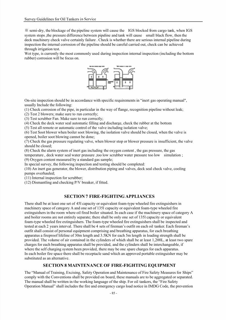
7/21/2019 Survey Guidelines for Tankers
http://slidepdf.com/reader/full/survey-guidelines-for-tankers 88/164
Survey Guidelines for Oil Tankers in Service
- 85 -
※ semi-dry, the blockage of the pipeline system will cause the IGS blocked from cargo tank, when IGS
system stops ,the pressure difference between pipeline and tank will cause small black flow, then the
deck machinery check valve certainly failure . Check is whether there are serious internal pipeline during
inspection the internal corrosion of the pipeline should be careful carried out, check can be achievedthrough irrigation test.Wet type, is currently the most commonly used during inspection internal inspection (including the bottom
rubber) corrosion will be focus on.
On-site inspection should be in accordance with specific requirements in “inert gas operating manual",usually Include the following:
(1) Check corrosion of the pipe, in particular in the way of flange, recognition pipeline without leak;
(2) Test 2 blowers; make sure to run correctly;(3) Test scrubber Fan. Make sure to run correctly;(4) Check the deck water seal automatic filling and discharge, check the rubber at the bottom
(5) Test all remote or automatic control of the valve including isolation valve;(6) Test Soot blower when boiler soot blowing, the isolation valve should be closed, when the valve is
opened, boiler soot blowing cannot be done;(7) Check the gas pressure regulating valve, when blower stop or blower pressure is insufficient, the valve
should be closed;(8) Check the alarm system of inert gas including the oxygen content , the gas pressure, the gas
temperature , deck water seal water pressure ,too low scrubber water pressure too low simulation ;(9) Oxygen content measured by a standard gas sample;
In special survey, the following inspection and testing should be completed:
(10) An inert gas generator, the blower, distribution piping and valves, deck seal check valve, cooling pumps overhauled;(11) Internal inspection for scrubber;
(12) Dismantling and checking P/V breaker, if fitted.
SECTION 7 FIRE-FIGHTING APPLIANCES
There shall be at least one set of 45l capacity or equivalent foam-type wheeled fire extinguishers inmachinery space of category A and one set of 135l capacity or equivalent foam-type wheeled fire
extinguishers in the room where oil fired boiler situated. In each case if the machinery space of category Aand boiler rooms are not entirely separate; there shall be only one set of 135l capacity or equivalent
foam-type wheeled fire extinguishers. The foam-type wheeled fire extinguishers shall be inspected andtested at each 2 years interval. There shall be 4 sets of fireman’s outfit on each oil tanker. Each fireman’s
outfit shall consist of personal equipment comprising and breathing apparatus, for each breathingapparatus a fireproof lifeline of 30m length and 3.5KN for each 5m length in loading strength shall be
provided. The volume of air contained in the cylinders of which shall be at least 1,200L, at least two sparecharges for each breathing apparatus shall be provided, and the cylinders shall be interchangeable, if
where the self charging system been provided, there may be one spare charges for each apparatus.In each boiler fire space there shall be receptacle sand which an approved portable extinguisher may be
substituted as an alternative.
SECTION 8 MAINTENANCE OF FIRE-FIGHTING EQUIPMENT
The “Manual of Training, Excising, Safety Operation and Maintenance of Fire Safety Measures for Ships”comply with the Conventions shall be provided on board, these manuals are to be aggregated or separated.
The manual shall be written in the working language of the ship. For oil tankers, the “Fire SafetyOperation Manual” shall includes the fire and emergency cargo load notice in IMDG Code, the prevention

7/21/2019 Survey Guidelines for Tankers
http://slidepdf.com/reader/full/survey-guidelines-for-tankers 89/164
Survey Guidelines for Oil Tankers in Service
- 86 -
of fire caused by the ignition of flammable vapours spreading to cargo area and the procedure of venting
and gas freeing of cargo tanks.A training manual shall be provided in each crew mess room and recreation room or in each crew cabin.
All the crew shall arrange the inspection and maintenance in accordance with the manual in time, andarrange the testing and survey in accordance with the requirements of relevant Flag Administration.
SECTION 9 EQUIVALENCE OF DESIGN AND ARRANGEMENTS OF THEFIRE-FIGHTING EQUIPMENT
According to the relevant provisions of SOLAS Convention, Fire safety design and arrangements maydeviate from the prescriptive requirements set out in Convention, provided that the design and
arrangements meet the fire safety objectives and the functional requirements. The documents approved byAdministration or CCS shall be kept on board.

7/21/2019 Survey Guidelines for Tankers
http://slidepdf.com/reader/full/survey-guidelines-for-tankers 90/164
Survey Guidelines for Oil Tankers in Service
- 87 -
CHAPTER 6, POLLUTION PREVENTION OF OIL TANKER
SECTION 1 CRUDE OIL WASHING SYSTEM
1. Requirements of crude oil washing system
Crude oil tankers of 20000 dwt and above delivered after June 1, 1982 as defined in MARPOL are to be
equipped with cargo oil tank washing systems by using crude oil washing.The equipments and arrangements of crude oil washing apparatus and associated equipment shouldcomply with the requirements of “Specifications for the Design, Operation and Control of Crude OilWashing Systems” which adopted by IMO.
The “Specifications for the Design, Operation and Control of Crude Oil Washing Systems (resolution
A.446 (XI)” has been adopted by IMO on 15 November 1979.The amendment of Resolution A.446 (XI), as amended by A.497 (XII) has been adopted by IMO on 19 November 1981.
The amendment A.897 (21) of Resolution A.446 (XI), as amended by Resolution A.497 (II) has beenadopted by IMO on 25 November 1999.
Every oil tanker operating with crude oil washing systems is to be provided with an Operations andEquipment Manual detailing the system and equipment and specifying operational procedures. Such a
Manual is to be in standard format in the Appendix of Resolution MEPC.3(XII) as amended byMEPC.81(43). If the Manual is not compiled in English or French, the text is to include a translation into
one of these languages.
2. The effectiveness verification of COW system (IMO Resolution A.897(21))
The Administration should ensure that the system complying with the requirements of Convention withinone year after the tanker was first engaged in the trade of carrying crude oil or by the end of the third
voyage carrying crude oil suitable for crude oil washing (whichever occurs later) and serves as the basis of performance survey to verify crude oil washing system and final certification (IOPP).
To confirm the effectiveness of the crude oil washing system and stripping system, the crude oil washingoperation should be witnessed to the satisfaction of the Administration.
a) For ships that comply with Convention, the crude oil washing operations are to be carried out using theapproved crude oil washing equipment and as specified in the approved Operations and Equipment
Manual. For at least one tank of a group of tanks of similar configuration, the Administration should:(i) Confirm the operation of the stripping system by observing the monitoring devices and monitoring the
oil level (by dipping or other means) during bottom washing.(ii) Monitor the proper operation of the washing machines with particular reference to supply pressure,
cycle times and machine function.On completion of washing and final draining, the tanks are to be hand dipped, as close as practical to theforward end, centre and aft end in each tank and a record of these dips should be made in the COW
Manual. An Administration may require an internal examination as described in subparagraph (b)(i) of this
section, or by an alternative method acceptable to the Administration, if deemed necessary. b) For ships other than those complying with Convention, where fitted with cargo tanks intended to beused in certain circumstances as ballast tanks, the following requirements apply in addition to those
specified in paragraph (a) of this section:
(i) To ensure that the tank is essentially free of clingage and deposits, the Administration may require that
the cleanliness of the tank be confirmed by a visual inspection made by entering the tanks after a crude oilwashing but prior to any water rinse which may be specified in the Operations and Equipment Manual. If
the tanks cannot be gas freed for safe entry of the surveyor, an internal examination should not be
conducted and the stripping test specified in paragraph (b)(ii) will be acceptable.In this case, the bottom of the tank to be inspected may be flushed with water and stripped in order toremove any wedge of liquid crude oil remaining on the tank bottom before gas-freeing for entry. If the
flushing procedure is adopted, a similar but unflushed tank must be used for the test specified in (ii) below.
(ii) To verify the effectiveness of the stripping and drainage arrangements, a measurement should be madeof the amount of oil floating on top of the departure ballast. The ratio of the volume of oil on top of thetotal departure ballast water to the volume of tanks that contain this water should not exceed 0.00085. This
test should be carried out after crude oil washing and stripping in a tank similar in all relevant respects to
the tank examined in accordance with (b)(i) above, which has not been subjected to a water rinse or to the
intervening water flushing permissible in (b)(i) above.(iii) To verify the design, installation and operation of the system, the arrival ballast, after a typical ballast

7/21/2019 Survey Guidelines for Tankers
http://slidepdf.com/reader/full/survey-guidelines-for-tankers 91/164
Survey Guidelines for Oil Tankers in Service
- 88 -
voyage before which the arrival ballast tanks have been crude oil washed and during which the tanks have
been water rinsed in accordance with the programme set out in the Operations and Equipment Manual,should be totally discharged to the loading port harbour through an Oil Discharged Monitoring and
Control (ODM) system approved by the Administration. The oil content of the effluent in this test shouldnot exceed 15 ppm. Alternatively, the option of taking ballast water samples to be analysed in a
shore-based laboratory is also acceptable.
(c) During all COW system surveys, internal visual inspections of the tanks by inspectors should not beconsidered a mandatory requirement. When an Administration considers that there is a possible failure ofthe COW system indicated by other COW survey requirements, the Administration may require an internalexamination of the tanks involved. Internal examinations may be completed using alternative methods,
e.g., video survey or other new technology, as accepted by the Administration."
SECTION 2 OIL DISCHARGE MONITORING AND CONTROL SYSTEM
1. Oil discharge monitoring and control system
Oil tankers of 150 gross tonnage and above shall be equipped with an oil discharge monitoring and control
system approved by the Administration. The oil discharge monitoring and control system shall be designedand installed in compliance with the guidelines and specifications for oil discharge monitoring and control
system for oil tankers developed by IMO, including:For oil content meters installed on oil tankers built prior to 2 October 1986, refer to the Recommendation
on international performance and test specifications for oily-water separating equipment and oil contentmeters adopted by the Organization by resolution A.393(X);For oil content meters as part of discharge monitoring and control systems installed on oil tankers built on
or after 2 October 1986, refer to the Guidelines and specifications for oil discharge monitoring and controlsystems for oil tankers adopted by the Organization by resolution A.586(14);
For oil content meters as part of discharge monitoring and control systems installed on oil tankers the keelof which are laid or which are in a similar stage of construction on or after 1 January 2005, refer to the
revised Guidelines and specifications for oil discharge monitoring and control systems for oil tankersadopted by the Organization by resolution MEPC.108(49).
Oil Discharge Monitoring and Control Systems for Oil Tankers Implementation Requirements List
Feature CategoryI II III IV(a) IV(b) V(a) V(b)
Applicability On or after 1January 2005
New≥4k
New≥4k
New
<4k
Existing≥20k
Existing≥20k
Input data
PPmDischarge flow rate
Ship speedTime and date
Starting interlockOverboard discharge valvecontrol
A A A A A A A A
A A M M M M A/M A/M
A A M M M M A/M A/M
A A A A A A M M
A A A A
A A A
Input data
Litres/Knot
Total quantity of oildischargedTime and date
PPm
A A A A A A A/M A/M
A A A A A A AM M
A A A A A A M MA A A A A A A
System comprises Control unit Computing unit Calculating unit
After 2 October 1986 A B
Note:
New—Ships delivered on or after 31 December 1979 as defined in ConventionExisting—Ships delivered before 31 December 1979 as defined in ConventionK---1,000 deadweight tones
A---Automatic inputM---Manual input of the date from system
2. Operational manuals for oil discharge monitoring and control systems
The operational instruction book of oil discharge monitoring and control system is to be complied withapproved operational manuals.

7/21/2019 Survey Guidelines for Tankers
http://slidepdf.com/reader/full/survey-guidelines-for-tankers 92/164
Survey Guidelines for Oil Tankers in Service
- 89 -
The Oil Discharge Monitoring and Control System Operational Manual is to contain all the details
necessary to operate and maintain the system and should include at least the following information. Theinformation may be grouped as indicated, or in an equivalent manner.
Introduction: Particulars of the ship, together with the date on which the system was/is to be installed andindex to remainder of manual.
Section 1: Manufacturer's equipment manuals for major components of the system. These may include
installation, commissioning, operating and fault finding procedures for the oil content monitor.Section 2: Operations manual comprising a description of the ship's cargo ballast systems, designatedoverboard discharges with sampling points, normal operational procedures, automatic inputs, manualinputs (as applicable), starting interlock and discharge valve control (as applicable), override system,
audible and visual alarms, outputs recorded and, where required for manual input, flow rate when
discharging by gravity and when pumping ballast overboard. It should also include instructions for thedischarge of oily water following mal-function of the equipment. The above information is to be supported by copies of relevant approved diagrams. Reference may be made to Section 1, where applicable.
Section 3: Technical manual comprising fault finding schedules, maintenance record and electrical,
pneumatic and hydraulic schematic diagrams and descriptions of the complete system.Reference may be made to Section 1, where applicable.Section 4: Test and check-out procedures to include a functional test at installation and guidance notes for
the Surveyors carrying out initial and in-service surveys. Reference may be made to Section 1, whereapplicable.Appendix I: Technical installation specification including location and mounting of components,arrangements for maintaining integrity of 'safe' zones, safety requirements for electrical equipment
installed in hazardous zones supported by copies of approved drawings, sample piping layout and sample
delay calculations, design and arrangements of sampling probes, flushing arrangements and zero setting.Reference may be made to Section 1, where applicable.Appendix II: Copy of Type Approval Certificate and Workshop Certificates for major components.
3. Installation requirements of Oil Discharge Monitoring and Control System
1. Basic principles1.1 The basic safety principle for the installation of cargo oil discharge monitoring and control system on
board oil tankers is that the parts of the system containing cargo oily-water mixture and oil vapour are to be completely, physically separated from all sources of ignition including the parts of the systemcontaining electric and electronic components.1.2 The parts of the system containing cargo oily-water mixture and oil vapour are to be entirely contained
within cargo area (for instance, cargo pump room), unless expressly provided otherwise in theseGuidelines.
1.3 The electric and electronic components are to be entirely contained in gas safe spaces, unless they areof certified intrinsically safe type1.
2. ApplicationAt the present the following types of systems are known to be available and are considered for the purpose
of these Guidelines as far as their installation on board is concerned:(a) Systems utilising transmission of light through bulkhead between dangerous spaces and gas safe spaces
and with the measuring cell located in gas dangerous spaces. The transmission of the light may be made by means of:
(i) optic fibres, or(ii) lens fitted in the above bulkhead;
(b) systems where the entire measuring instrument is located in gas safe spaces.3. Fire safety provisions
3.1 Systems utilizing optic fibersBy their conception and when properly installed these systems meet the basic principle stated under 1.1.
3.2 Systems utilizing bulkhead lensThe bulkhead lens shall comply with F9 in so far its protection against mechanical damage, its strengthand its resistance to fire are concerned. Additionally the lens and the parts of the system located in the gas
safe spaces shall be protected by a steel casing constructed to at least A-O Standard having doors which
are gas-tight. These doors shall be provided with a notice which requires that they be kept closed at all
times when the system is not in use.1 See Recommendations published by International Electro technical Commission and, in particular, Publication 92

7/21/2019 Survey Guidelines for Tankers
http://slidepdf.com/reader/full/survey-guidelines-for-tankers 93/164
Survey Guidelines for Oil Tankers in Service
- 90 -
"Electrical Installation in Ships."
3.3 Systems where the entire measuring instrument is located in gas safe spaces3.3.1 Sampling lines passing through bulkhead or deck between gas dangerous and gas safe spaces shall
have, as a rule, a maximum inside diameter of 12 mm. If such a diameter needs to be greater, thearrangement is to be specially considered on case by case basis. The relevant pipes are to be heavy gauge
steel or of other metallic material resistant to sea water corrosion.
3.3.2 Any bulkhead penetration for pipes shall be welded on both sides.3.3.3 Any bulkhead penetration for shaft driving pumps shall comply with F13.3.3.4 The entire measuring instrument shall be located as close as possible to the bulkhead and the
sampling lines shall be kept as short as possible.3.3.5 The entire measuring instrument which is directly connected with the sampling lines shall be fitted in
a gas-tight casing.3.3.6 Such a casing shall be fitted with mechanical ventilation, of exhaust type, arranged to the satisfaction
of the Classification Society. Provision shall be made to ventilate the casing prior to putting the systeminto operation and a warning notice requiring the use of such a ventilation shall be placed outside thecasing.
3.3.7 The compartment of the instrument containing the oily-water components shall be separated from the
compartment containing the electric and electronic components by means of a gas-tight division.
3.3.8 Stop valves shall be fitted in the sampling lines (both suction and return line) on the gas safe spaceside as close to the bulkhead penetration as possible. The following notice shall be fitted at the valves: "To
be closed when the measuring instrument is not in use." In addition, on the return line a water-seal deviceshall be fitted on the gas dangerous space side.
3.3.9 The casing shall be fitted with system suitable for the detection of vapour or gases of oils. Thearrangement of the system shall be to the satisfaction of the Classification Society.
3.3.10 Whenever the casing is opened, the oily-water sampling pumps shall be automatic all stopped.3.3.11 Oily-water samples taken from gas dangerous spaces shall be returned to these spaces.
3.3.12 If fitted, the safety valve in the sampling line shall be located on the gas dangerous space side.3.3.13 The system shall be hydrostatically tested with pressure not less than the opening pressure of the
safety valve. If safety valve is not arranged, the whole system shall be hydrostatically tested with at least1.5 times the working pressure of cargo/ballast pump.
4.
OthersThe accuracy of Oil Discharge Monitoring Equipment which complied with MEPC.108 (49) should be
verified by manufacturer or persons authorized by the manufacturer at the IOPP renewal surveys. Thecalibration certificate certifying date of last calibration check should be retained on board for inspection
purposes.The recording device of a control section should include a digital printer, which may be formatted
electronically if preferred. The recorded parameters should be explicitly identified on the printout. The printout should be legible and should remain so once removed from the recording device and should be
retained for at least three years.
SECTION 3 OIL/WATER INTERFACE DETECTOR
Oil tankers of 150 gross tonnage and above shall be provided with effective oil/water interface detectors
approved by the Administration for a rapid and accurate determination of the oil/water interface in sloptanks and shall be available for use in other tanks where the separation of oil and water is effected and
from which it is intended to discharge effluent direct to the sea.The oil/water interface detectors usually are potable, and type of UTI is commonly used on board which
shown as below:

7/21/2019 Survey Guidelines for Tankers
http://slidepdf.com/reader/full/survey-guidelines-for-tankers 94/164
Survey Guidelines for Oil Tankers in Service
- 91 -
SECTION 4 OILY WATER DISCHARGE CONTROL
1. Oily water discharge
1.1 Discharges outside special areasAny discharge into the sea of oil or oily mixtures from the cargo area of an oil tanker except the discharge
of clean or segregated ballast, shall be prohibited except when all the following conditions are satisfied:.1 the tanker is not within a special area;
.2 the tanker is more than 50 nautical miles from the nearest land;
.3 the tanker is proceeding en route;
.4 the instantaneous rate of discharge of oil content does not exceed 30 litres per nautical mile;
.5 the total quantity of oil discharged into the sea does not exceed for tankers delivered on or before 31
December 1979, as defined in regulation 1.28.1, 1/15,000 of the total quantity of the particular cargo ofwhich the residue formed a part, and for tankers delivered after 31 December 1979, as defined in
regulation 1.28.2, 1/30,000 of the total quantity of the particular cargo of which the residue formed a part;and.6 the tanker has in operation an oil discharge monitoring and control system and a slop tank arrangement
as required by regulations 29 and 31 of this Annex.
1.2 Discharges in special areasAny discharge into the sea of oil or oily mixture from the cargo area of an oil tanker except the dischargeof clean or segregated ballast shall be prohibited while in a special area. Nothing in this regulation shall
prohibit a ship on a voyage only part of which is in a special area from discharging outside the special area
in accordance with paragraph 1 of this regulation.
1.3
For oil tankers of less than 150 gross tonnage, the control of discharge of oil under this regulationshall be effected by the retention of oil on board with subsequent discharge of all contaminated washings
to reception facilities. The total quantity of oil and water used for washing and returned to a storage tank
shall be discharged to reception facilities unless adequate arrangements are made to ensure that anyeffluent which is allowed to be discharged into the sea is effectively monitored to ensure that the provisions of this regulation are complied with.
1.4 The oil residues which cannot be discharged into the sea in compliance with the regulation shall be
retained on board for subsequent discharge to reception facilities.
2. Oil Record Book (Cargo/ballast operations)
2.1 Every oil tanker of 150 gross tonnage and above shall be provided with an Oil Record Book Part II
(Cargo/Ballast Operations). The Oil Record Book Part II, whether as a part of the ship's official logbook or
otherwise, shall be in the Form specified in appendix III to this Annex.2.2 The Oil Record Book Part II shall be completed on each occasion, on a tank-to-tank basis if

7/21/2019 Survey Guidelines for Tankers
http://slidepdf.com/reader/full/survey-guidelines-for-tankers 95/164
Survey Guidelines for Oil Tankers in Service
- 92 -
appropriate, whenever any of the following cargo/ballast operations take place in the ship:
.1 loading of oil cargo;
.2 internal transfer of oil cargo during voyage;
.3 unloading of oil cargo;
.4 ballasting of cargo tanks and dedicated clean ballast tanks;
.5 cleaning of cargo tanks including crude oil washing;
.6 discharge of ballast except from segregated ballast tanks;
.7 discharge of water from slop tanks;
.8 closing of all applicable valves or similar devices after slop tank discharge operations;
.9 closing of valves necessary for isolation of dedicated clean ballast tanks from cargo and stripping lines
after slop tank discharge operations; and
.10 disposal of residues.2.3 For oil tankers with COW system, the total quantity of oil and water used for washing and returned toa storage tank shall be recorded in the Oil Record Book Part II.
2.4 In the event of such discharge of oil or oily mixture as is referred to in regulation 4 of this Annex or
in the event of accidental or other exceptional discharge of oil not excepted by that regulation, a statementshall be made in the Oil Record Book Part II of the circumstances of, and the reasons for, the discharge.2.5 Each operation described in paragraph 2 of this regulation shall be fully recorded without delay in the
Oil Record Book Part II so that all entries in the book appropriate to that operation are completed. Eachcompleted operation shall be signed by the officer or officers in charge of the operations concerned andeach completed page shall be signed by the master of ship. The entries in the Oil Record Book Part II shall be at least in English, French or Spanish. Where entries in an official language of the State whose flag the
ship is entitled to fly are also used, this shall prevail in case of dispute or discrepancy.
2.6 Any failure of the oil discharge monitoring and control system shall be noted in the Oil Record BookPart II.2.7 The Oil Record Book shall be kept in such a place as to be readily available for inspection at all
reasonable times and, except in the case of unmanned ships under tow, shall be kept on board the ship. It
shall be preserved for a period of three years after the last entry has been made.2.8 The competent authority of the Government of a Party to the Convention may inspect the Oil RecordBook Part II on board any ship to which this Annex applies while the ship is in its port or offshore
terminals and may make a copy of any entry in that book and may require the master of the ship to certifythat the copy is a true copy of such entry. Any copy so made which has been certified by the master of theship as a true copy of an entry in the ship's Oil Record Book Part II shall be made admissible in any judicial proceedings as evidence of the facts stated in the entry. The inspection of an Oil Record Book Part
II and the taking of a certified copy by the competent authority under this paragraph shall be performed asexpeditiously as possible without causing the ship to be unduly delayed.
2.9
SECTION 5 VAPOR EMISSION CONTROL SYSTEM
The Vapor Emission Control System is only still the requirement of a part of port and CCS Rules hasgiven a detailed technical requirements. It is taken into account that the system will be required by more
ports, a brief introduction has been made here.1. Plan and documents
The following plans and documents are to be submitted for approval by ships and which are to be kept on board for the inspection of the relevant port:(1) Diagrammatic plan of vapor emission control system, means connection of venting/IGS, drainage
arrangements;
(2) Calculation sheet, including cargo load and un-load rate, the setting of P/V valve.(3) Cargo tank gauging system, overfilling system and setting, alarm system;(4) Hazardous area locations
2. The vapor collection system is not to interfere with the proper operation of the cargo tank venting
system. When inert gas distribution piping is used for vapor collection piping, means to isolate the inertgas supply from the vapor collection system are to be provided, the valve can be used to isolate the inertgas supply. a draining and recovery device is to be fitted on the vapor emission control system. If a tanker
simultaneously collects vapor from incompatible cargoes, it is to keep these incompatible vapors separate
throughout the entire vapor collection system.Shore connection should be as close as the side area of loading station, where a manual quick-close valve

7/21/2019 Survey Guidelines for Tankers
http://slidepdf.com/reader/full/survey-guidelines-for-tankers 96/164
Survey Guidelines for Oil Tankers in Service
- 93 -
should be installed. The flange of the shore connection is to be complied with standard of ANSI B16.5
Class 150, the connection flange is to be fitted with a permanently protruding stud (diameter 12.7mm,length less than 25.4mm) for the alignment with steam hose, the diameter of 16mm hole in the steam hose
flange is to be fitted relatively. Each vapor manifold is to be for the last 1m in front of external connectionflange painted on its exterior surfaces with red/yellow/red. The red bands are 100 mm wide and the yellow
in the center is 800mm wide and labeled “VAPOUR” in black letters at least 50 mm high.
The connection hose is to be complied with:(1) a maximum working pressure of at least 0.034 MPa;(2) the capacity of withstanding at least 0.014 MPa vacuum without collapsing or constricting;(3) qualified with 5 times burst pressure test;
(4) effective electrical continuity;
(5) resistance to abrasion and kinking.The closed gauging arrangement should be fitted in the cargo tank, if the portable gauging system has beenfitted, the quantity of which should meet the needs of all cargo tanks which loading and unloading
simultaneously and two extra spare.
The high level alarms and overfill alarms are to be fitted in cargo tanks, which are to be capable of givingaudible and visual alarm indications at the cargo transfer control room, the overfill alarm is to be givenaudible and visual alarm indications at the cargo transfer control room and in the deck cargo area.

7/21/2019 Survey Guidelines for Tankers
http://slidepdf.com/reader/full/survey-guidelines-for-tankers 97/164
Survey Guidelines for Oil Tankers in Service
- 94 -
CHAPTER 7, ADDITIONAL REQUIREMENTS RELATED TO OIL TANKERS
SECTION 1 STEERING GEAR SYSTEM
1. Requirements of steering gear
For every ship, two separate steering gears shall be fitted, which can fitted with:
(1) Main steering gear and auxiliary steering gear, or(2) Where main steering gear power units are fitted in duplicate, no auxiliary steering gear need berequired, but each steering gear should be independently and can be operated in parallel.
Where the main steering gear comprises two or more identical power units, an auxiliary steering gear neednot be fitted, the two sets of independent steering system are to be fitted; Each steering gear has a
independent steering gear control system, which are as following:(1) Mode A: 2 sets steering gears have been fitted, each steering gear system can be controlled solely from
bridge house and steering gear room, and each steering gear meets the requirement of “28s”, that is the 2sets main steering gear which meets the requirements of steering operation independently.
(2) Mode B: 2 sets steering gears have been fitted, each steering gear system can be controlled solely from bridge house and steering gear room, but each steering gear system cannot meet the requirements of “28s”
when in solely operation, only two sets of steering gear system operate in parallel can meet therequirements of “28s”.
(3) C Mode: 2 sets or more steering gears have been fitted, each steering gear system can be controlledsolely from bridge house and steering gear room, but each steering gear system cannot meet therequirements of “28s” when in solely operation, only two sets of steering gear system operate in parallel
can meet the requirements of “28s”. If 3 sets identical steering gears fitted, every two sets of steering gears
operate in parallel, which is mean that 3 sets steering gears can meet the requirements of “28s”, comparedwith 2 sets steering gears fitted, the power of a single steering gear can be reduced by 50%.Oil tanker of 10,000 GT and above only can adopted the steering gear arrangement of Model A and Model
C, which is capable of putting the rudder over from 35oon one side to 30
o not more than 28s. Oil tanker
under 10,000 GT can adopted Model A, Model B and Model C which can comply with SOLAS, because
of the steering gear is capable putting the rudder over from 35°on one side to 30°not more than 28
while all the power unit in operation which required by SOLAS. It also can fit with main steering gear and
auxiliary steer gear that both of them meet the required steering time.

7/21/2019 Survey Guidelines for Tankers
http://slidepdf.com/reader/full/survey-guidelines-for-tankers 98/164
Survey Guidelines for Oil Tankers in Service
- 95 -
SECTION 2 EMERGENCY TOWING ARRANGEMENTS
An emergency towing arrangement shall be fitted at both ends on board all tankers of not less than 20,000
tonnes deadweight as defined in regulation II-1/3.21 constructed on or after 1 January 1996. For tankersconstructed before 1 January 1996, such an arrangement shall be fitted at the first scheduled dry-docking
after 1 January 1996 but not later than 1 January 1999. The emergency towing arrangements which fitted
at fore usually used as bow single point mooring. The following figure is the typical constitute of bothends emergency towing arrangement on oil tanker:
The pick-up rope of stern emergency towing arrangement described as pick-up gear in CCS rules, and
which for the convenience of picking up the towing rope of tug.
Requirements of Major Components of Towing Arrangements Table of CCS Rules
Major components Location Strength requirements
Fore Aft
Pick-up gear Optional Yes /
Towing pennant Optional Yes Yes
Chafing gear Yes Depending on design Yes
Fairlead Yes Yes Yes
Strongpoint Yes Yes Yes
Roller pedestal Yes Depending on design /
Safe Working Load of ComponentsDeadweight of ship (t) Safe working load (KN)
20,000 to 50,000 1000
≥50,000 2000
The components of emergency towing arrangement should be inspected according to the design drawingsand the consistency with drawings should be confirmed and the component should be maintained. The
condition of reinforced side and their reinforced member under deck of emergency towing arrangementsshould be inspected and kept in good condition, no serious corrosion and exceeded surface defects.

7/21/2019 Survey Guidelines for Tankers
http://slidepdf.com/reader/full/survey-guidelines-for-tankers 99/164
Survey Guidelines for Oil Tankers in Service
- 96 -
SECTION 3 WATCH WINDOWS IN BALLAST TANK
In accordance with the requirements of Oil Companies, the watch windows are to be fitted on the manhole
cover of oil tanker ballast tank. From the technical point of manhole, it should not undermine the strengthand watertight integrity of manhole covers. No specific provisions have been made in CCS rules, the
actual design of the watch windows are generally based on the JIS F2317-1981. The specific parameters of
the watch windows which fitted in the manhole cover with coaming are as follows:DN Inner Dia. of
holeInner Dia. ofcover groove
OD ofcover
Thicknessof cover
Height ofcoaming
Thickness ofcoaming
Lockingmeans
200 200 190 250 10 180 10 Center
spiral,locking
downward
260 260 250 310 10 180 10 Center
spiral,locking
downward
SECTION 4 LIFE-SAVING APPLIANCES FOR OIL TANKERS
The life-saving appliances for oil tankers and general cargo ships are approximately the same, the specificdifferences are as follows:
1. Oil tankers apply to 1960 SOLAS (Keel laid before 25 May 1980):
one or more motor lifeboats of such aggregate capacity on each side of the ship as will accommodate thetotal number of persons on oil tanker, one of the lifeboat carried on oil tankers less than 1,600 GT may benon-motor type, additionally, the liferaft is to be carried as will accommodate the half number of persons
on board.
2. Oil tankers apply to 1974 SOLASCompared with 1960 SOLAS, there is a little changes in the requirements of life saving appliances: Everytanker of 3,000 GT and upwards shall carry not less than four lifeboats, two lifeboats shall be carried aft
and two amidships, except that in tankers which have no amidships superstructure all lifeboats shall becarried aft. Provided that, if in the case of tankers with no amidships superstructure it is impracticable to
carry four lifeboats aft, the Administration may permit instead the carriage aft of one lifeboat on each sideof the ship. In such a case:
(1) each stern side of the ship should be carried one lifeboat;(2) each such lifeboat shall not exceed 8 meters(26 feet) in length;
(3) each such lifeboat shall be stowed as far as practicable, but at least so far forward that the after end ofthe lifeboat is one-and-a-half times the length of the lifeboat forward of the propeller;
(4) each lifeboat shall be stowed as near the sea level as is safe and practicable;3. Oil tankers apply to 1974 SOLAS, 1981 amendment(Keel laid on or after 1 September 1984)
Compared with 1974 SOLAS, the arrangement of life saving appliance did not changed, only therequirement of the lighting shall be capable of being supplied for at least three hours by the emergency
source of power at the position of lifeboat embarkation stations been added.4. Oil tankers apply to 1974 SOLAS, 1983 amendment (Keel laid on or after 1 July 1986)
Compared with 1974 SOLAS, the arrangements of life saving appliance have undergone major changes,and the requirements are as follows:
(1) One or more fire-protected lifeboats of such aggregate capacity on each side of the ship as willaccommodate the total number of persons on oil tankers which carrying cargoes having a flashpoint not
exceeding 60℃(closed cup test). In addition to complying with the requirements of total enclosed lifeboats,
a self-contained air support system and a water spray system shall be arranged for fire-protected lifeboat.(2) Cargo ships where the survival craft are stowed in a position which is more than 100 m from the stem
or stern shall carry a liferaft stowed as far forward or aft, or one as far forward and another as far aft inaddition, as is reasonable and practicable.
(3) At least one rescue boat shall be carried on oil tankers, a lifeboat may be accepted as a rescue boat, provided that is also complies with the requirements for a rescue boat.
(4) One or more liferafts of such aggregate capacity as will accommodate the total number of persons on
board.(5) The lifebuoy self-igniting lights on tankers shall be a battery type.

7/21/2019 Survey Guidelines for Tankers
http://slidepdf.com/reader/full/survey-guidelines-for-tankers 100/164
Survey Guidelines for Oil Tankers in Service
- 97 -
(6) For a period of 3h, emergency lighting at every at muster and embarkation station and over sides as
required.5. Oil tankers apply to 1974 SOLAS, 1996 amendment (Keel laid on or after 1 July 1998)
6. 1974 SOLAS 1996 amendment introduced LSA Code which required that all life-saving appliancesand arrangements shall comply with the applicable requirements of the Code. No great changes have been
taken for life saving appliance, but the details requirement of technology standard of life saving appliance
has been made as follows:(1) The requirements of free-fall launched over the stern of the ship in lieu of the lifeboat which shall becarried on each side have been added.(2) For a period of 18h, emergency lighting at every at muster and embarkation station and over sides as
required.
The life saving appliances equipped on board shall meet the requirements of current conventions, the shipis to meet the requirements of conventions which applied on the period of shipbuilding at least, if it isconsidered impracticable. The life saving appliances which are vulnerable or have expiry date are to
comply with the current conventions. The equipments new installed or renewed during repairing are to
comply with the current conventions, if the life boat has been renewed but the original lifeboat davit has been kept, the original type of lifeboat was acceptable.
SECTION 5 OTHERS
The flammable gas in the segregate ballast tanks of cargo area double hull and double bottom is to bedetected which applied to oil tankers constructed (Keel Laid) on or after 1 October 1994. The means ofdetection can be as fixed flammable gas detection system in segregate ballast tank or portable flammable
gas detector which is capable for wet environments.In addition, two(2) sets of portable oxygen/flammable gas detectors and flammable vapor detectors are to
be provided on oil tankers, which are to be tested periodically. For periodical testing of the detectors, theconventions does not mandate the intervals, but ship companies are to arrange this testing every year as
required by Oil Industries Organizations. It is taking into account that the gas risk of cargo area, theself-igniting light of lifebuoy in cargo area is battery type as required by SOLAS, and aluminum gangway
is to avoid connecting to the hull directly.

7/21/2019 Survey Guidelines for Tankers
http://slidepdf.com/reader/full/survey-guidelines-for-tankers 101/164
Survey Guidelines for Oil Tankers in Service
- 98 -
CHAPTER 8, BRIEF INTRODUCTION OF THE INSPECTION RAISED BY
OILCOMPANIES
To ensure that the safety of terminal facilities, personnel, cargo, oil tankers and marine environment, the
world’s main oil industries organizations and oil companies carries out the inspection for third partyoperated tankers (oil tanker, chemical tanker and liquefied gas carrier), including their chartered tankers,
tankers calling at their wharfs, tankers carrying their cargoes or to which they have an interest in. The oiltankers inspection carried by Oil Industries Organizations and Oil Companies not only related to ship’sdesign, construction and other aspects, but also related to ship company management and ship
management closely. Therefore, the Oil Industries Organizations/major Oil Companies have found theirown vetting or Inspection institutes, the inspectors of them include the experienced captain and chief
engineer, or experienced ship survey, shipbuilding and marine staff.

7/21/2019 Survey Guidelines for Tankers
http://slidepdf.com/reader/full/survey-guidelines-for-tankers 102/164
Survey Guidelines for Oil Tankers in Service
- 99 -
APPENDIX
ANNEX 1 MINIMUM REQUIREMENT OF THE INTERNAL EXAMINATIONS TO
ALL THE TANKS OF SELF-PROPELLED INTEGRATED OIL TANKERS
1 Requirements of annual survey
Shipage Internal examination Close up survey Structural test
1. Suspect areas in tanks;2. Required at last Special/intermediate survey;
3. Ballast tanks boundaries facing cargo tankswith heat means or fuel oil tanks within cargolength, coating condition of which is less than
good at previous special/intermediatesurvey.[Note 1]
-- --
Note 1:1 Double side space within the cargo length can only be water tank or void space, and fuel oil tank can be in the cargo
area.
2 Ballast tank means sea water ballast tank.3 In the cargo area, ballast tanks boundaries facing cargo tanks with heat means or fuel oil tanks, coating condition of
which is less than good at previous special/intermediate survey, internal examination to such ballast tanks are to be
carried out and thickness measurements are to be carried out as deemed necessary by the attending surveyor.
2 Requirements of intermediate survey(Beyond the requirements of annual survey, the following
to be included)Ship age Overall examination Close up survey Structural test
5~10 years All ballast tanks
>10 years In scope of last special survey
Note: Ballast tank means sea water ballast tank
3 Minimum Requirements for Close-Up Survey and thickness measurements at special survey of
oil tank
3.1 Minimum Requirements for Close-up Surveys at Hull Special Surveys of Oil Tankers, Ore/Oil Ships
and etc.

7/21/2019 Survey Guidelines for Tankers
http://slidepdf.com/reader/full/survey-guidelines-for-tankers 103/164
Survey Guidelines for Oil Tankers in Service
- 100 -
Special Survey No.1
Age ≤ 5
Special Survey No. 2
5 < Age ≤ 10
Special Survey No. 3
10 < Age ≤ 15
Special Survey No.4 and
Subsequent Age >
15
A) One web framering (in a ballastwing tank, if any,
or a cargo wingtank used primarily
for water ballast).B) One decktransverse (in a
cargo oil tank).D) One transverse
bulkhead (in a ballast tank).
D) One transverse bulkhead (in a
cargo oil tank).D) One transverse bulkhead (in a
cargo oil centretank)
A) All web frame rings (in a ballastwing tank, if any, or a in cargowing tank, used primarily for water
ballast).B) One deck transverse (in each of
the remaining ballast tanks, if any).B) One deck transverse (in a cargowing tank).
B) One deck transverse (in twocargo centre tanks).
C) Both transverse bulkheads (in awing ballast tank, if any, or a cargo
wing tank used primarily for water ballast.
D) One transverse bulkhead (ineach remaining ballast tank).D) One transverse bulkhead (in a
cargo oil wing tank).D) One transverse bulkhead (intwo cargo centre tanks)
A) All web frame rings (in all ballast tanks).A) All web frame rings (in a
cargo wing tank).A) A minimum of 30% (to be
rounded up to next whole integer) of all complete transverse webframe rings in each remaining
cargo wing tank.C) All transverse bulkheads (in all
cargo and ballast tanks.E) A minimum of 30%(to be
rounded up to next whole integer)
of deck and bottom transverses
including adjacent structuralmembers in each cargo centre tank.F) As considered necessary by the
Surveyor
The following structuralmembers subject toclose-up survey;
additional transversesincluded as deemed
necessary by CCS:A) All web frame rings(in all ballast tanks).
A) All web frame rings(in a
cargo wing tank).A) A minimum of 30%(to
be rounded up to next
whole integer) of all
complete transverse webframe rings in eachremaining cargo wing
tank.C) All transverse bulkheads (in all cargo
and ballast tanks.E) A minimum of 30%(to
be rounded up to next
whole integer) of deck
and bottom transversesincluding adjacent
structural members ineach cargo centre tank.F) As considered
necessary by the Surveyor
Notes:
A) Complete transverse web frame ring including adjacent structural members.B) Deck transverse including adjacent deck structural members.
C) Transverse bulkhead complete-including girder system and adjacent structural members.
D) Transverse bulkhead lower part-including girder system and adjacent structural members.
E) Deck and bottom transverse-including adjacent structural members.
F) Additional complete transverse web frame ring.
3.2 Minimum Requirements for Thickness Measurements at Hull Special Surveys of Oil Tankers, Ore/OilShips and etc.
Special Survey No. 1
Age ≤ 5 Special Survey No.
2
5 < Age ≤ 10
Special Survey No. 3
10 < Age ≤ 15 Special Survey No. 4 and
Subsequent
Age > 15
1) One section of deck plating for the full beam ofthe ship within the cargoarea (in way of a ballast
tank, if any, or a cargo tankused primarily for water
ballast)2) Measurements, for
general assessment andrecording of corrosion
pattern, of those structuralmembers subject toclose-up survey:
A) One web frame ring (in a
ballast wing tank, if any, ora cargo wing tank used primarily for water ballast).
1) Within the cargoarea:A) Each deck plate;B) One transverse
section.2) Measurements,
for generalassessment and
recording ofcorrosion pattern, of
those structuralmembers subject toclose-up survey:
A) All web frame
rings (in a ballastwing tank, if any, ora in cargo wing
1) Within the cargo area:A) Each deck plate;B) Two transverse sections;C) All wind and water strakes.
2) Measurements, for generalassessment and recording of
corrosion pattern, of thosestructural members subject to
close-up survey:A) All web frame rings (in all
ballast tanks).A) All web frame rings (in acargo wing tank).
A) A minimum of 30%(to be
rounded up to next wholeinteger) of all completetransverse web frame rings in
1) Within the cargo area:A) Each deck plate;B) Three transverse sections;C) Each bottom plate.
2) Measurements, for generalassessment and recording of
corrosion pattern, of those structuralmembers subject to
close-up survey:A) All web frame rings (in all ballast
tanks).A) All web frame rings (in a cargowing tank).
A) A minimum of 30%(to be
rounded up to next whole integer)
of all complete transverse webframe rings in each remaining cargo

7/21/2019 Survey Guidelines for Tankers
http://slidepdf.com/reader/full/survey-guidelines-for-tankers 104/164
Survey Guidelines for Oil Tankers in Service
- 101 -
B) One deck transverse (in
a cargo oil tank).D) One transverse bulkhead(in a ballast tank).
D) One transverse bulkhead(in a cargo oil tank).
D) One transverse bulkhead
(in a cargo oil centre tank)3) Suspect areas
tank, used primarily
for water ballast).B) One decktransverse (in each
of the remaining ballast tanks, if
any).
B) One decktransverse (in acargo wing tank).
B) One decktransverse (in twocargo centre tanks).
C) Both transverse bulkheads (in awing ballast tank, if
any, or a cargo wingtank used primarilyfor water ballast.
D) One transverse bulkhead (in each
remaining ballasttank).
D) One transverse bulkhead (in a cargo
oil wing tank).D) One transverse bulkhead (in two
cargo centre tanks)3) Suspect areas.
4) Selected windand water strakesoutside the cargo
area
each remaining cargo wing
tank.C) All transverse bulkheads (inall cargo and ballast tanks.
E) A minimum of 30%(to be
rounded up to next whole
integer) of deck and bottom
transversesincluding adjacent structuralmembers in each cargo centre
tank.F) As considered necessary bythe Surveyor
3) Suspect areas.4) Selected wind and waterstrakes outside the cargo area.
5) Internals in forepeak andafter peak tanks
wing tank.
C) All transverse bulkheads (in allcargo and ballast tanks.E) A minimum of 30%(to be
rounded up to next whole integer) ofdeck and bottom transverses
including adjacent structural
members in each cargo centre tank.F) As considered necessary by theSurveyor
3) Suspect areas.4) All wind and water strakes, fulllength
5) Internals in forepeak andafterpeak tanks6) All exposed main deck plating
outside the cargo area.7) Representative exposedsuperstructure deck plating (poop,
bridge, and forecastle deck)8) All keel plates full length. Also,
additional bottom plates in way ofcofferdams, machinery space, and
aft end of tanks9) Plating of sea chests. Shell
plating in way of overboarddischarges as considered necessary by the attending Surveyor
Notes:A) Complete transverse web frame ring including adjacent structural members.
B) Deck transverse including adjacent deck structural members.
C) Transverse bulkhead complete-including girder system and adjacent structural members.
D) Transverse bulkhead lower part-including girder system and adjacent structural members.
E) Deck and bottom transverse-including adjacent structural members.
F) Additional complete transverse web frame ring.
Remark: Thickness measurements of structures in areas where close-up surveys are required shall be carried out
simultaneously with close-up surveys.
3.3 Minimum Requirements for Close-up Surveys at Hull Special Surveys of Double Hull Oil Tankers
Special Survey No.
1
Age ≤ 5
Special Survey No. 2
5 < Age ≤ 10 Special Survey No. 3
10 < Age ≤ 15 Special Survey No.4 and Subsequent
Age > 15

7/21/2019 Survey Guidelines for Tankers
http://slidepdf.com/reader/full/survey-guidelines-for-tankers 105/164
Survey Guidelines for Oil Tankers in Service
- 102 -
(A) One web
frame(1), in a ballast tank (see Note 1)
(B) One decktransverse, in a
cargo oil tank (2)
(C) One transverse bulkhead(4), in acomplete ballast
tank(see Note 1)(D) One transverse
bulkhead (5) in acargo oil centre tank(E) One transverse
bulkhead(5), in acargo oil wing tank(see Note 2)
(A) All web frames (1), in a
ballast tank (see Note 1).(B) The knuckle area and theupper part (5 m
approximately) of one webframe in each remaining
ballast tank (6)
(C) One deck transverse, intwo cargo oil tanks (2)(D) One transverse
bulkhead(4), in each ballasttank(see Note 1)(E) One transverse
bulkhead(5), in two cargo oilcentre tanks(F) One transverse
bulkhead(5), in a cargo oilwing tank(see Note 2)
(A) All web frames (1), in
all ballast tanks(B) All web frames (7),
including deck transverseand cross ties, if fitted, in a
cargo oil tank.
(C) One web frame (7),including deck transverseand cross ties, if fitted, in
each remaining cargo oiltank(D) All transverse
bulkheads, in all cargo oil(3) and ballast(4) tanks
The following structural members
subject to close-up survey; additionaltransversesincluded as deemed necessary by
CCS:(A) All web frames (1), in all
ballast tanks
(B) All web frames (7),including deck transverse and crossties, if fitted, in a cargo oil tank.
(C) One web frame (7),including deck transverse and crossties, if fitted, in each remaining cargo
oil tank(D) All transverse bulkheads, in allcargo oil (3) and ballast
(4) tanks
(1) Web frame in a ballast tank means vertical web in side tank, hopper web in hopper tank, floor in double bottom tank and
deck transverse in double deck tank (where fitted), including adjacent structural members. In fore and aft peak tanks, webframe means a complete transverse web frame ring including adjacent structural members.(2) Deck transverse, including adjacent deck structural members (or external structure on deck in way of the tank, where
applicable).(3) Transverse bulkhead complete in cargo tanks, including girder system, adjacent structural members (such as longitudinal
bulkheads) and internal structure of lower and upper stools, where fitted.(4) Transverse bulkhead complete in ballast tanks, including girder system and adjacent structural members, such as
longitudinal bulkheads, girders in double bottom tanks, inner bottom plating, hopper side, connecting brackets.(5) Transverse bulkhead lower part in cargo tanks, including girder system, adjacent structural members (such as
longitudinal bulkheads) and internal structure of lower stool, where fitted.(6) The knuckle area and the upper part (5 m approximately), including adjacent structural members. Knuckle area is thearea of the web frame around the connections of the slope hopper plating to the inner hull bulkhead and the inner bottom
plating, up to 2 m from the corners both on the bulkhead and the double bottom.(7) Web frame in a cargo oil tank means deck transverse, longitudinal bulkhead vertical girder and cross ties, where fitted,including adjacent structural members.
Note 1: Ballast tank means double bottom tank plus double side tank plus double deck tank, as applicable, even if these
tanks are separate. Note 2: Where no centre cargo tanks are fitted (as in the case of center longitudinal bulkhead), transverse bulkheads in wing
tanks are to be surveyed.
3.4 Minimum Requirements for Thickness Measurements at Hull Special Surveys of Double Hull OilTankers
Special Survey No.1
Age ≤ 5
Special Survey No. 2
5 < Age ≤ 10 Special Survey No. 3
10 < Age ≤ 15 Special Survey No. 4 and Subsequent
Age > 15

7/21/2019 Survey Guidelines for Tankers
http://slidepdf.com/reader/full/survey-guidelines-for-tankers 106/164
Survey Guidelines for Oil Tankers in Service
- 103 -
1) One section of
deck plating for the full beam of the ship
within the cargoarea
2) Measurements,
forgeneral assessmentand
recording ofcorrosion pattern, of those
structural memberssubject to close-upsurvey:
(A) One webframe(1), in a ballast tank (see
Note 1)(B) One deck
transverse, in acargo oil tank (2)
(C) One transverse bulkhead(4), in a
complete ballasttank(see Note 1)
(D) One transverse bulkhead (5) in a
cargo oil centre tank(E) One transverse bulkhead(5), in a
cargo oil wing tank(see Note 2)
3) Suspect areas
1) Within the cargo area:
A) Each deck plate;B) One transverse section.2) Measurements, for general
assessment and recording ofcorrosion pattern, of those
structural members subject to
close-up survey:(A) All web frames (1), in a ballast tank (see Note 1).
(B) The knuckle area and theupper part (5 mapproximately) of one web
frame in each remaining ballast tank (6)(C) One deck transverse, in
two cargo oil tanks (2)(D) One transverse bulkhead(4), in each ballast
tank(see Note 1)(E) One transverse
bulkhead(5), in two cargo oilcentre tanks
(F) One transverse bulkhead(5), in a cargo oil
wing tank(see Note 2)3) Suspect areas.4) Selected wind and water
strakes outside the cargo area
1) Within the cargo area:
A) Each deck plate;B) Two transverse sections
(at least one section is to
include a ballast tank within
0.5 L amidships)
C) All wind and waterstrakes.
2) Measurements, forgeneral assessment and
recording of corrosion pattern, of those structuralmembers subject to
close-up survey:(A) All web frames (1), inall
ballast tanks(B) All web frames (7),including deck transverse
and cross ties, if fitted, in acargo oil tank.
(C) One web frame (7),including deck transverse
and cross ties, if fitted, ineach remaining cargo oil
tank(D) All transverse bulkheads, in all cargo oil
(3) and ballast(4) tanks 3) Suspect areas.4) Selected wind and waterstrakes outside the cargo
area.5) Internals in forepeak and
afterpeak tanks
1) Within the cargo area:
A) Each deck plate;
B) Three transverse sections(at least
one section is to include a ballast tank
within 0.5 L amidships) C) Each bottom plate.
2) Measurements, for generalassessment and recording of corrosion
pattern, of those structural memberssubject to
close-up survey:(A) All web frames (1), in all ballasttanks
(B) All web frames (7), includingdeck transverse and cross ties, iffitted, in a cargo oil tank.
(C) One web frame (7), includingdeck transverse and cross ties, iffitted, in each remaining cargo oil
tank(D) All transverse bulkheads, in all
cargo oil (3) and ballast(4) tanks3) Suspect areas.
4) All wind and water strakes,fulllength
5) Internals in forepeak and afterpeaktanks6) All exposed main deck plating
outside the cargo area.7) Representative exposed
superstructure deck plating (poop, bridge, and forecastle deck)8) All keel plates full length. Also,
additional bottom plates in way ofcofferdams, machinery space, and aft
end of tanks9) Plating of sea chests. Shell plating
in way of overboard discharges asconsidered necessary by the attending
Surveyor
(1) Web frame in a ballast tank means vertical web in side tank, hopper web in hopper tank, floor in double bottom tank anddeck transverse in double deck tank (where fitted), including adjacent structural members. In fore and aft peak tanks, web
frame means a complete transverse web frame ring including adjacent structural members.(2) Deck transverse, including adjacent deck structural members (or external structure on deck in way of the tank, where
applicable).(3) Transverse bulkhead complete in cargo tanks, including girder system, adjacent structural members (such as longitudinal
bulkheads) and internal structure of lower and upper stools, where fitted.(4) Transverse bulkhead complete in ballast tanks, including girder system and adjacent structural members, such as
longitudinal bulkheads, girders in double bottom tanks, inner bottom plating, hopper side, connecting brackets.(5) Transverse bulkhead lower part in cargo tanks, including girder system, adjacent structural members (such aslongitudinal bulkheads) and internal structure of lower stool, where fitted.
(6) The knuckle area and the upper part (5 m approximately), including adjacent structural members. Knuckle area is thearea of the web frame around the connections of the slope hopper plating to the inner hull bulkhead and the inner bottom
plating, up to 2 m from the corners both on the bulkhead and the double bottom.(7) Web frame in a cargo oil tank means deck transverse, longitudinal bulkhead vertical girder and cross ties, where fitted,including adjacent structural members.
Note 1: Ballast tank means double bottom tank plus double side tank plus double deck tank, as applicable, even if thesetanks are separate.
Note 2: Where no centre cargo tanks are fitted (as in the case of center longitudinal bulkhead), transverse bulkheads in wing
tanks are to be surveyed.Remark: Thickness measurements of structures in areas where close-up surveys are required shall be carried out

7/21/2019 Survey Guidelines for Tankers
http://slidepdf.com/reader/full/survey-guidelines-for-tankers 107/164

7/21/2019 Survey Guidelines for Tankers
http://slidepdf.com/reader/full/survey-guidelines-for-tankers 108/164
Survey Guidelines for Oil Tankers in Service
- 105 -
Ship
age
Overall examination Close up survey Structural test
≤5 years
(1st
special
survey)
All tanks within cargo area, ballast tanks,including double bottom tanks, pump
rooms, pipe tunnels, cofferdams, voidspaces, duck keel, dry space, machinery
space and super structures to be internalinspected.
One web frame(1), in a ballasttank (see Note 3)
One deck transverse, in a cargo oiltank (2)
One transverse bulkhead(4), in acomplete ballast tank(see Note 3)
One transverse bulkhead (5) in acargo oil centre tank
One transverse bulkhead(5), in acargo oil wing tank (see Note 4)
All ballast tank boundariesCargo tank boundaries
facing ballast tanks,void spaces, pipe tunnels,
pump-rooms orcofferdams[note 2]
5<age≤10
years
(2nd
special
survey)
3. Same as the requirements for oiltank 5 years and below;
4. One fresh water tank
All web frames (1), in a ballasttank (see Note 3).
The knuckle area and theupper part (5 m approximately) of
one web frame in each remaining ballast tank (6)One deck transverse, in two cargo
oil tanks (2)One transverse bulkhead(4), ineach ballast tank(see Note 3)
One transverse bulkhead(5), intwo cargo oil centre tanksOne transverse bulkhead(5), in a
cargo oil wing tank(see Note 4)
All ballast tank boundariesAll cargo tank bulkheads
[note 2]
≥10
years
4. Same as the requirements for oiltank 5 years and below;
5. One fuel oil tank in engine room
6. All fresh water tanks
All web frames (1), in all ballast tanksAll web frames (7),
including deck transverse andcross ties, if fitted, in a cargo oil
tank.
One web frame (7),including deck transverse andcross ties, if fitted, in each
remaining cargo oil tankAll transverse bulkheads, in allcargo oil (3) and ballast tanks(4)
Same as above
(1) Web frame in a ballast tank means vertical web in side tank, hopper web in hopper tank, floor in double bottom tank anddeck transverse in double deck tank (where fitted), including adjacent structural members. In fore and aft peak tanks, web
frame means a complete transverse web frame ring including adjacent structural members.(2) Deck transverse, including adjacent deck structural members (or external structure on deck in way of the tank, where
applicable).(3) Transverse bulkhead complete in cargo tanks, including girder system, adjacent structural members (such as longitudinal bulkheads) and internal structure of lower and upper stools, where fitted.
(4) Transverse bulkhead complete in ballast tanks, including girder system and adjacent structural members, such aslongitudinal bulkheads, girders in double bottom tanks, inner bottom plating, hopper side, connecting brackets.
(5) Transverse bulkhead lower part in cargo tanks, including girder system, adjacent structural members (such aslongitudinal bulkheads) and internal structure of lower stool, where fitted.(6) The knuckle area and the upper part (5 m approximately), including adjacent structural members. Knuckle area is the
area of the web frame around the connections of the slope hopper plating to the inner hull bulkhead and the inner bottom plating, up to 2 m from the corners both on the bulkhead and the double bottom.
(7) Web frame in a cargo oil tank means deck transverse, longitudinal bulkhead vertical girder and cross ties, where fitted,including adjacent structural members.
Note 3: Ballast tank means double bottom tank plus double side tank plus double deck tank, as applicable, even if these
tanks are separate. Note 4: Where no centre cargo tanks are fitted (as in the case of center longitudinal bulkhead), transverse bulkheads in wingtanks are to be surveyed.

7/21/2019 Survey Guidelines for Tankers
http://slidepdf.com/reader/full/survey-guidelines-for-tankers 109/164
Survey Guidelines for Oil Tankers in Service
- 106 -
APPENDIX 2: INSPECTIONS TO CRITICAL STRUCTURAL AREAS
1. Critical Structural Areas of double hull oil tanks with transverse supporting members in center
oil tanks (more attention paid to cut-outs for deck longitudinal of Single side oil tank)
2. Critical Structural Areas of double hull oil tanks with transverse supporting members in center
oil tanks (more attention paid to cut-outs for deck longitudinal of Single side oil tank)
3. Critical Structural Areas of transverse web structural members (more attention paid to cut-outs
for deck longitudinal of Single side oil tank)
No scallop
Stress concentration area
Not in line area
Collar plating at opposite side of bracket toe
Not in line area

7/21/2019 Survey Guidelines for Tankers
http://slidepdf.com/reader/full/survey-guidelines-for-tankers 110/164
Survey Guidelines for Oil Tankers in Service
- 107 -
4. Critical Structural Areas of double bottom structures of Slop tanks( Special attention to
inspection of not in line area)
Stress concentration area

7/21/2019 Survey Guidelines for Tankers
http://slidepdf.com/reader/full/survey-guidelines-for-tankers 111/164
Survey Guidelines for Oil Tankers in Service
- 108 -

7/21/2019 Survey Guidelines for Tankers
http://slidepdf.com/reader/full/survey-guidelines-for-tankers 112/164
Survey Guidelines for Oil Tankers in Service
- 109 -

7/21/2019 Survey Guidelines for Tankers
http://slidepdf.com/reader/full/survey-guidelines-for-tankers 113/164
Survey Guidelines for Oil Tankers in Service
- 110 -

7/21/2019 Survey Guidelines for Tankers
http://slidepdf.com/reader/full/survey-guidelines-for-tankers 114/164
Survey Guidelines for Oil Tankers in Service
- 111 -
5. Critical Structural Areas of horizontal girder of transverse bulkhead connection to inner shell
6. Critical Structural Areas of fore hull structures(Above light water line to freeboard deck)

7/21/2019 Survey Guidelines for Tankers
http://slidepdf.com/reader/full/survey-guidelines-for-tankers 115/164
Survey Guidelines for Oil Tankers in Service
- 112 -

7/21/2019 Survey Guidelines for Tankers
http://slidepdf.com/reader/full/survey-guidelines-for-tankers 116/164
Survey Guidelines for Oil Tankers in Service
- 113 -

7/21/2019 Survey Guidelines for Tankers
http://slidepdf.com/reader/full/survey-guidelines-for-tankers 117/164
Survey Guidelines for Oil Tankers in Service
- 114 -

7/21/2019 Survey Guidelines for Tankers
http://slidepdf.com/reader/full/survey-guidelines-for-tankers 118/164
Survey Guidelines for Oil Tankers in Service
- 115 -
APPENDIX 3 TYPICAL STRUCTURE DETAILS FAILURES AND
RECOMMENDED REPAIRS
Group No.1 Connection of longitudinals to transverse webs
Location: Connection of longitudinals to transverse webs No.1
Example No.1: Web and flat bar fractures at cut-outs for longitudinal stiffener connections
Typical Damage Proposed Repair
Factors which may have caused damage:
1.
Asymmetrical connection of flat bar stiffener resulting
in high peak stresses at the heel of the stiffener underfatigue loading.
2.
Insufficient area of connection of longitudinal to web
plate.3. Defective weld at return around the plate thickness.
4. High localised corrosion at areas of stressconcentration such as flat bar stiffener connections,
corners of cut-out for the longitudinal and connection
of web to shell at cut-outs.5. High shear stress in the web of the transverse.6. Dynamic sea way loads/ship motions.
Notes on repairs:
1.
Web plate cropped and partly renewed, but for
small fractures, the fracture can be ground,veed-out, welded-up, and examined by NDT.
2.
Collar plates to be fitted.
3. Backing brackets to be added.

7/21/2019 Survey Guidelines for Tankers
http://slidepdf.com/reader/full/survey-guidelines-for-tankers 119/164
Survey Guidelines for Oil Tankers in Service
- 116 -
Location: Connection of longitudinals to transverse websExample No.2: Side shell fractures at cut-outs for longitudinal stiffenerconnections
No.1
Typical Damage Proposed Repair
Factors which may have caused damage:
1.
Insufficient area of connection of longitudinal to
web plates.2. Defective weld at return around the plate thickness.
3. Localised corrosion associated with the stressconcentrations in way of the longitudinal connection
of web to shell.4. Dynamic sea way loads/ship motions.
5. High shear stress in the transverse web.
Notes on repairs:
1. Web plate cropped and partly renewed, but for
small fractures, the fracture can be ground,veed-out, welded-up, and examined by NDT.
2. Collar plates to be fitted.
3. Backing brackets to be added.

7/21/2019 Survey Guidelines for Tankers
http://slidepdf.com/reader/full/survey-guidelines-for-tankers 120/164
Survey Guidelines for Oil Tankers in Service
- 117 -
Location: Connection of longitudinals to transverse webs
Example No.3: Side shell fractures due to single lug onunderside
No.1
Typical Damage Proposed Repair
Factors which may have caused damage:
1. Single lug fitted into bosom of longitudinal (instead ofat. the heel side) resulting in greater deflections of the
longitudinal due to dynamic loads and therefore higherstress at the upper edge of the cut-out adjacent to the
shell.2. Fracture in web flat bar stiffener connection resulting
in greater deflection of longitudinal.
3. Defective weld at return around the plate thickness.4. Dynamic sea way loads/ship motions.
Notes on repairs:
1. Web plate cropped and partly renewed, but forsmall fractures, the fracture can be ground,
veed-out, welded-up, and examined by NDT.
2. Collar plates to be fitted.
3. Backing brackets to be added.

7/21/2019 Survey Guidelines for Tankers
http://slidepdf.com/reader/full/survey-guidelines-for-tankers 121/164
Survey Guidelines for Oil Tankers in Service
- 118 -
Location: Connection of longitudinals to transverse webs No.1
Example No.4: Web and flat bar fractures with face plate attached to underside of web Flat barlap welded
Typical Damage Proposed Repair
Factors which may have caused damage:
1. Asymmetrical connection of flat bar stiffener resultingin high peak stresses at the heel of the stiffener underfatigue loading.
2. Fabricated longitudinal with welding onto the exposededge of the web resulting in poor fatigue strength of
the connection of the longitudinal to the flat bar.3. Insufficient area of connection of longitudinal to web
plate.
4. Defective weld at return around the plate thickness.5. High localised corrosion at areas of stress
concentration, such as flat bar stiffener connection,corner of cut-out for longitudinal and connection of
lug to shell at cut-outs.6. High shear stress in the web of the transverse.
7. Dynamic sea way loads/ship motions.
Notes on repairs:
1. Web plate cropped and partly renewed, but forsmall fractures, the fracture can be ground,veed-out, welded-up, and examined by NDT.
2. Collar plates to be fitted.
3. Backing brackets to be added.
Not recommended

7/21/2019 Survey Guidelines for Tankers
http://slidepdf.com/reader/full/survey-guidelines-for-tankers 122/164
Survey Guidelines for Oil Tankers in Service
119
Location: Connection of longitudinals to transverse webs No.1
Example No.5: Web and longitudinal fractures. Face plate attached to underside of web. Flat bar lap welded.
Typical Damage Proposed Repair
Factors which may have caused damage:
1. Asymmetrical connection of flat bar stiffener resulting
in high peak stresses at the heel of the stiffener underfatigue loading.
2.
Higher tensile steel longitudinal resulting in greater
stresses.3. Fabricated longitudinal with welding onto the exposed
edge of the web resulting in poor fatigue strength of the
connection of the longitudinal to the flat bar.4. Insufficient area of connection of longitudinal to web
plate.5. Defective weld at return around the plate thickness.
6. High localised corrosion at areas of stress concentration,
such as flat bar stiffener connection, corner of cut-outfor longitudinal and connection of lug to shell atcut-outs.
7.
High shear stress in the web of the transverse.
8. Dynamic sea way loads/ship motions.
Notes on repairs:
1. Web plate cropped and partly renewed, but for
small fractures, the fracture can be ground,veed-out, welded-up, and examined by NDT.
2. Collar plates to be fitted.
3. Backing brackets to be added.
Not recommended

7/21/2019 Survey Guidelines for Tankers
http://slidepdf.com/reader/full/survey-guidelines-for-tankers 123/164

7/21/2019 Survey Guidelines for Tankers
http://slidepdf.com/reader/full/survey-guidelines-for-tankers 124/164
Survey Guidelines for Oil Tankers in Service
- 121 -
Location: Connection of longitudinals to transverse webs. No.1
Example No.7: Web and longitudinal fractures. Face plate attached to underside of web. Flat bar butt welded.
Typical Damage Proposed Repair
Factors which may have caused damage:
1. Asymmetrical connection of flat bar stiffener resulting
in high peak stresses at the heel of the stiffener underfatigue loading.
2. Higher tensile steel longitudinal resulting in greaterstresses.
3.
Fabricated longitudinal with welding onto the exposed
edge of the web resulting in poor fatigue strength of theconnection of the longitudinal to the flat bar.
4.
Insufficient area of connection of longitudinal to web
plate.5.
Defective weld at return around the plate thickness.
6.
High localised corrosion at areas of stress concentration,such as flat bar stiffener connection, corner of cut-out
for longitudinal and connection of lug to shell atcut-outs.
7. High shear stress in the web of the transverse.8. Dynamic sea way loads/ship motions.
Notes on repairs:
1. Web plate cropped and partly renewed, but for small
fractures, the fracture can be ground, veed-out,welded-up, and examined by NDT.
2. Collar plates to be fitted.
3. Backing brackets to be added.

7/21/2019 Survey Guidelines for Tankers
http://slidepdf.com/reader/full/survey-guidelines-for-tankers 125/164
Survey Guidelines for Oil Tankers in Service
- 122 -
Location: Connection of longitudinals to transverse webs. No.1
Example No.8: Fractured side shell longitudinal at tripping bracket connection. No backing bracket.
Typical Damage Proposed Repair
Factors which may have caused damage:
1.
Asymmetrical connection of bracket resulting in high
peak stresses at the heel of the single large bracket underfatigue loading.
2.
Higher tensile steel longitudinal resulting in greater
stresses.3. Fabricated longitudinal having the face plate attached to
the underside of the web (where fitted) and with weldingonto the exposed edge of the web. This results in poor
fatigue strength of the connection of the longitudinal webto the tripping bracket.
4. Asymmetric longitudinals resulting in additionaltorsional stresses.
5.
Defective weld at return around the plate thickness.
6. Increased stress if only a single connection is employedin way of the transverse web cut-outs.
7.
Dynamic sea way loads/ship motion.
Notes on repairs:
1.
Longitudinal to be cropped and partly renewed.
2. Backing brackets to be added.3. Additional collar plate to be fitted at the
transverse web cut-out.

7/21/2019 Survey Guidelines for Tankers
http://slidepdf.com/reader/full/survey-guidelines-for-tankers 126/164

7/21/2019 Survey Guidelines for Tankers
http://slidepdf.com/reader/full/survey-guidelines-for-tankers 127/164
Survey Guidelines for Oil Tankers in Service
- 124 -
Group No.2 Connection of longitudinals to plane transverse bulkheads.
Location: Connection of longitudinals to plane transverse bulkheads. No.2
Example No.1: Fractured side shell longitudinal. Bulkhead horizontally stiffened.
Typical Damage Proposed Repair
Factors which may have caused damage:
1.
Asymmetrical connection of bracket in associationwith a backing bracket which is too small. This resultsin high stress at the toe of the smaller bracket under
fatigue loading.2. Higher tensile steel longitudinal resulting in greater
stresses.
3. Fabricated longitudinal having the face plate attachedto the underside of the web (where fitted) and with
welding onto the exposed edge of the web. This resultsin poor fatigue strength of the connection of the
longitudinal web to the bracket.4. Asymmetric longitudinal resulting in additional
torsional stresses.5. Horizontally stiffened transverse bulkhead causing
increased end moments at the side shell longitudinal
connection resulting from loading on the transverse bulkhead.
6.
Deflection of the adjacent side shell transverse under
load.7.
Defective weld at return around the plate thickness.
8. Dynamic sea way loads/ship motions.
Notes on repairs:
1.
Longitudinal to be cropped and partly renewed.2. Backing brackets to be added.

7/21/2019 Survey Guidelines for Tankers
http://slidepdf.com/reader/full/survey-guidelines-for-tankers 128/164
Survey Guidelines for Oil Tankers in Service
- 125 -
Location: Connection of longitudinals to plane transverse bulkheads No.2
Example No.2: Fractured bulkhead end bracket at side shell. Bulkhead horizontally stiffened.
Typical Damage Proposed Repair
Factors which may have caused damage:
1. Large unconnected ending of bulkhead stiffener
associated with an asymmetrical connection resultingin high stresses at the heel of the stiffener and the
bracket.2. Horizontally stiffened transverse bulkheads causing
increased end moment at the side shell longitudinal
connection resulting from loading on the transverse bulkhead.
3.
Deflection of the adjacent side shell transverse under
load.4.
Defective weld at return around plate thickness.
5.
Dynamic sea way loads/ship motions.
Notes on repairs:
1. Fractured bulkhead repaired by weld and fractured
bracket partly renewed.2. Additional collar plate to be fitted.
3. Backing brackets to be added.

7/21/2019 Survey Guidelines for Tankers
http://slidepdf.com/reader/full/survey-guidelines-for-tankers 129/164
Survey Guidelines for Oil Tankers in Service
- 126 -
Location: Connection of longitudinals to plane transverse bulkheads
Example No.3: Fractured side shell longitudinal at forward transverse bulkhead
No.2
Typical Damage Proposed Repair
Factors which may have caused damage:
1. Under-designed end bracket.2.
Higher tensile steel side shell longitudinal resulting ingreater stresses.
3. Fabricated longitudinal having the face plate attachedto the underside of the web (where fitted) and with
welding onto the exposed edge of the web. This resultsin poor fatigue strength of the connection of the
longitudinal to the bracket.4. Deflection of the adjacent side shell transverse under
load.5. Defective weld at return around the plate thickness.6.
Dynamic sea way loads/ship motions of forward end of
ship.
Notes on repairs:
1. Longitudinal to be cropped and partly renewed.2.
Increased bracket with soft toes.

7/21/2019 Survey Guidelines for Tankers
http://slidepdf.com/reader/full/survey-guidelines-for-tankers 130/164
Survey Guidelines for Oil Tankers in Service
- 127 -
Location: Connection of longitudinals to plane transverse bulkheads.
Example No.4: Fractured side shell longitudinal at transverse bulkhead buttress
No.2
Typical Damage Proposed Repair
Factors which may have caused damage:
1. Under-designed end bracket.2.
Higher tensile steel side shell longitudinal resulting in
greater stresses.
3.
Fabricated longitudinal having the face plate attachedto the underside of the web (where fitted) and withwelding onto the exposed edge of the web. This resultsin poor fatigue strength of the connection of the
longitudinal web to the bracket.4. Deflection of the adjacent transverse web frame under
load.
5. Defective weld at return around the plate thickness.6. Dynamic sea way loads/ship motions.
7. Asymmetric longitudinal resulting in additionaltorsional stresses.
Notes on repairs:
1. Longitudinal to be cropped and partly renewed.2.
Increased bracket with soft toes.

7/21/2019 Survey Guidelines for Tankers
http://slidepdf.com/reader/full/survey-guidelines-for-tankers 131/164
Survey Guidelines for Oil Tankers in Service
- 128 -
Group No.3 Connection of longitudinals to corrugated transverse bulkheads
Location: Connection of longitudinals to corrugated transverse bulkheads No.3
Example No.1: Bulkhead fracture at toe of horizontal flat bar stiffener. Vertically corrugated
bulkhead.
Typical Damage Proposed Repair
Factors which may have caused damage:
1. Sniped stiffener ending close to corrugation knuckle
forming a hard spot under deflection of the corrugationand rotation of the longitudinal.
2.
Insufficient stiffener end connection at the knuckle in
the corrugation.3. Dynamic seaway loads/ship motions.
Notes on repairs:
1. Bulkhead to be cropped and partly renewed or
repaired by weld.2. New flat bar stiffener to be fitted.

7/21/2019 Survey Guidelines for Tankers
http://slidepdf.com/reader/full/survey-guidelines-for-tankers 132/164
Survey Guidelines for Oil Tankers in Service
- 129 -
Location: Connection of longitudinals to corrugated transverse bulkheads No.3
Example No.2: Bulkhead fractured at passage of side longitudinal. Bulkhead horizontallycorrugated.
Typical Damage Proposed Repair
Factors which may have caused damage:
1. Inadequate connection between side longitudinal andhorizontal corrugation.
2. Large span of horizontal corrugation.3. Dynamic seaway loads/ship motions.
Notes on repairs:
1. Backing brackets to be added.2.
Additional collar plate with increased thickness
(125%) to be fitted at cut-outs.

7/21/2019 Survey Guidelines for Tankers
http://slidepdf.com/reader/full/survey-guidelines-for-tankers 133/164
Survey Guidelines for Oil Tankers in Service
- 130 -
Group No.4
Connection of longitudinals to floors in the double bottom
Location: Connection of longitudinals to floors in the double bottom No.4
Example No.1: Fractured stiffener connection to bottom and inner bottom longitudinals
Typical Damage Proposed Repair
Factors which may have caused damage:
1. Asymmetric connection leading to high local stressesat the connection of vertical stiffeners of the transverse
floors to the inner and outer bottom longitudinals.2. Wide slot for longitudinal leads to inefficient lug
connection.
3. Sharp corners or flame-cut edges producing a notcheffect.
4. Incomplete/defective weld at stiffener connection tothe longitudinals.
5. Dynamic sea way loads/ship motions.
Notes on repairs:
1. Additional collar plate to be fitted.
2. Backing brackets to be added.

7/21/2019 Survey Guidelines for Tankers
http://slidepdf.com/reader/full/survey-guidelines-for-tankers 134/164
Survey Guidelines for Oil Tankers in Service
- 131 -
Group No.5
Fore Peak Tank
Location: Forepeak structure. No.5
Example No.1: Fractured vertical web at the longitudinal stiffener ending in way of the parabolic
bow structure
Typical Damage Proposed Repair
Factors which may have caused damage:
1. Stress concentrations at bracket ending due toinadequate support at bracket toes in way of
connection to web frame members.2. Localised thinning in way of coating failure at bracket
endings due to flexing of the structure.
3. Dynamic seaway loadings at bow causing flexing at bracket endings.
Notes on repairs:
1. Insert plates with increased thickness below bracketending.
2. Additional backing brackets with stiffeners to beadded.

7/21/2019 Survey Guidelines for Tankers
http://slidepdf.com/reader/full/survey-guidelines-for-tankers 135/164
Survey Guidelines for Oil Tankers in Service
- 132 -
Location: Forepeak structure No.5
Example No.2: Fractured stringer end connection in way of the parabolic bow structure
Typical Damage Proposed Repair
Factors which may have caused damage:
1. High stress concentration at connection of stringer to
stiff girder/deep web intersection due to discontinuityof face plate.
2. Localised thinning in way of coating failure at stringerconnection due to flexing of the structure.
3.
Dynamic seaway loadings at bow causing flexing in
way of detail
Notes on repairs:
1. Insert plate with increased thickness at connection.
2.
Modified face plate connection.

7/21/2019 Survey Guidelines for Tankers
http://slidepdf.com/reader/full/survey-guidelines-for-tankers 136/164
Survey Guidelines for Oil Tankers in Service
- 133 -
Location: Forepeak structure
Example No.3: Fracture at end of longitudinal at bow structure
No.5
Typical Damage Proposed Repair
Factors which may have caused damage:
1.
Inadequate brackets forming the longitudinal endingsat bow structure.
2. Localised thinning in way of coating failure at
longitudinal endings due to flexing of the structure.3. Dynamic seaway loadings at bow causing flexing at
longitudinal endings.
Notes on repairs:
1.
Modified taper of toes to a minimum of 1:3.2. Insert web plate with increased thickness with soft
toes.
3. Modified taper of face plate to a minimum of 1:3.

7/21/2019 Survey Guidelines for Tankers
http://slidepdf.com/reader/full/survey-guidelines-for-tankers 137/164
Survey Guidelines for Oil Tankers in Service
- 134 -
Location: Forepeak structure No.5
Example NO.4: Fracture at toe of web frame bracket connection to stringer platform bracket
Typical Damage Proposed Repair
Factors which may have caused damage: 1. Inadequate bracket forming the web frame connection
to the stringer.
2. Localised thinning in way of coating failure at bracketdue to flexing of the structure.
3.
Dynamic seaway loadings in way of bow flair.
Notes on repairs: 1. Modified taper of toes to a minimum of 1:3.2.
Insert web plate with increased thickness with soft
toes.3. Modified taper of face plate to a minimum of 1:3.

7/21/2019 Survey Guidelines for Tankers
http://slidepdf.com/reader/full/survey-guidelines-for-tankers 138/164
Survey Guidelines for Oil Tankers in Service
- 135 -
Location: Forepeak structure No.5
Example No.5: Fracture and buckle of bow transverse web frame in way of longitudinal cut-outs
Typical Damage Proposed Repair
Factors which may have caused damage:
1.
Localised thinning in way of coating failure at cut-outs
and sharp edges due to working of the structure.2.
Dynamic seaway loadings in way of bow flair.
Notes on repairs:
1.
Insert web plate with additional stiffeners and
increased thickness.

7/21/2019 Survey Guidelines for Tankers
http://slidepdf.com/reader/full/survey-guidelines-for-tankers 139/164
Survey Guidelines for Oil Tankers in Service
- 136 -
Location: Fore peak structure
Example No.6: Buckled and tripped breast hooks
No.5
Typical Damage Proposed Repair
Factors which may have caused damage:
1. Bow impact load.
2.
Low buckling resistance
Notes on repairs:
1. Tripping brackets to be added at breast hooks

7/21/2019 Survey Guidelines for Tankers
http://slidepdf.com/reader/full/survey-guidelines-for-tankers 140/164
Survey Guidelines for Oil Tankers in Service
- 137 -
Group No.6
Longitudinal girder end brackets
Location: Longitudinal girder end brackets No.6
Example No.1: Fractured bottom centre line girder at the end bracket connection to O.T. bulkhead
Typical Damage Proposed Repair
Factors which may have caused damage:
1. Stress concentration at bracket toe.
2. Insufficient taper on sniped end of bracket face plate.3. High shear stress level in the longitudinal girder due to
stringer reaction.
Notes on repairs:
1. Modified taper of face plate to a minimum of 1:3.
2. Insert plate at cut-outs below bracket toes.3. Backing brackets to be added.

7/21/2019 Survey Guidelines for Tankers
http://slidepdf.com/reader/full/survey-guidelines-for-tankers 141/164
Survey Guidelines for Oil Tankers in Service
- 138 -
Location: Longitudinal girder end brackets No.6
Example No.2: Fractured and buckled buttress in way of bracket connection to O.T. bulkhead.
Typical Damage Proposed Repair
Factors which may have caused damage:
1. Panel stiffening on girder web not fitted in way of bracket toe.
2.
Stress concentration at bracket toe.3. Local dry-docking loads.
Notes on repairs:
1. Increased bracket size.2. Additional panel stiffeners to be fitted.

7/21/2019 Survey Guidelines for Tankers
http://slidepdf.com/reader/full/survey-guidelines-for-tankers 142/164
Survey Guidelines for Oil Tankers in Service
- 139 -
Location: Longitudinal girder end brackets No.6
Example No.3: Fractured vertical web bracket connection to bottom centerline girder
Typical Damage Proposed Repair
Factors which may have caused damage:
1.
Inadequate end bracket to vertical web resulting in
high nominal stress.2.
Bracket toe having inadequate taper resulting in stress
concentration.3. Insufficient buckling strength of the bracket face plate.
Notes on repairs:
1.
Increased bracket size with soft toes.
2.
Full penetration weld at bracket toes.

7/21/2019 Survey Guidelines for Tankers
http://slidepdf.com/reader/full/survey-guidelines-for-tankers 143/164
Survey Guidelines for Oil Tankers in Service
- 140 -
Location: Longitudinal girder end brackets No.6
Example No.4: Buckled and fractured vertical web and bottom centre line girder bracketconnection
Typical Damage Proposed Repair
Factors which may have caused damage:
1. Insufficient panel stiffening on vertical web.2.
Stress concentration at bracket toes with sniped face
plate.
Notes on repairs:
1. Insert web plate with increased thickness.2.
Bracket toes partly renewed.
3. Additional stiffeners connected to face plate.

7/21/2019 Survey Guidelines for Tankers
http://slidepdf.com/reader/full/survey-guidelines-for-tankers 144/164
Survey Guidelines for Oil Tankers in Service
- 141 -
Location: Longitudinal girder end brackets
Example No.5: Fractured bottom girder brackets in way of pipe opening
No.6
Typical Damage Proposed Repair
Factors which may have caused damage:
1. Insufficient throat through bracket in way of pipeopening.
2.
Stress concentration at pipe opening.
Notes on repairs:
1. Enlarged bracket.2. Additional stiffeners of bracket to be fitted.3.
Insert web plate with increased thickness/additional
stiffeners4. Full penetration weld at bracket.

7/21/2019 Survey Guidelines for Tankers
http://slidepdf.com/reader/full/survey-guidelines-for-tankers 145/164
Survey Guidelines for Oil Tankers in Service
- 142 -
Location: Longitudinal girder end brackets No.6
Example No.6: Fractured and buckled bottom side girder in way of end connections to O.T. bulkhead.
Typical Damage Proposed Repair
Factors which may have caused damage: 1. Inadequately sized bracket connection at end of girder.2.
Insufficient panel stiffening on girder web in way of
end bracket.
Notes on repairs: 1. Additional panel stiffeners to be fitted.2.
Enlarged bracket and increased face plate radius.

7/21/2019 Survey Guidelines for Tankers
http://slidepdf.com/reader/full/survey-guidelines-for-tankers 146/164
Survey Guidelines for Oil Tankers in Service
- 143 -
Location: Longitudinal girder end brackets No.6
Example No.7: Fractured intercostal bottom girder fitted without an end bracket in way of thewash bulkhead.
Typical Damage Proposed Repair
Factors which may have caused damage:
1. Inadequate end connection of girder to the wash bulkhead.
Notes on repairs:
1. Insert web plate with increased thickness.2. Additional bracket to be fitted.

7/21/2019 Survey Guidelines for Tankers
http://slidepdf.com/reader/full/survey-guidelines-for-tankers 147/164
Survey Guidelines for Oil Tankers in Service
- 144 -
Group No.7
Transverse web frame end brackets
Location: Transverse web frame end brackets No.7
Example No.1: Fractured wing tank deck transverse bracket. Continuous face plate.
Typical Damage Proposed Repair
Factors which may have caused damage:
1. Abrupt reduction of face plate thickness and width.
2. Taper and butt weld in face plate located in cornerradius where high stresses exist.
3.
Stress concentration due to scallop in the web plate.
4. Defective butt weld at face plate taper.
Notes on repairs:
1. Web plate and face plate to be cropped and partly
renewed.2. Modified taper of face plate.

7/21/2019 Survey Guidelines for Tankers
http://slidepdf.com/reader/full/survey-guidelines-for-tankers 148/164
Survey Guidelines for Oil Tankers in Service
- 145 -
Location: Transverse web frame end brackets
Example No.2: Fractured wing tank deck transverse bracket. Face plate sniped.
No.7
Typical Damage Proposed Repair
Factors which may have caused damage:
1. Stress concentration at bracket face plate sniped end.2.
Defective weld or material at the face plate snipe.
Notes on repairs:
1. Web plate and face plate to be cropped and partlyrenewed.
2.
Additional backing stiffeners with tripping bracketsto be fitted.

7/21/2019 Survey Guidelines for Tankers
http://slidepdf.com/reader/full/survey-guidelines-for-tankers 149/164
Survey Guidelines for Oil Tankers in Service
- 146 -
Location: Transverse web frame end brackets No.7
Example No.3: Fractured centre tank bottom transverse end brackets. Asymmetrical face plate.
Typical Damage Proposed Repair
Factors which may have caused damage:
1. Bracket face plate in way of toe with insufficient taper.
2. Localised corrosion at bracket toe.3. Insufficient bracket size resulting in high nominal
stress.4. Deficient weld around bracket toe.
Notes on repairs:
1. Web plate and face plate to be cropped and partly
renewed with increased thickness and soft toes.2. Additional stiffeners to be fitted.
3. Additional collar plate to be fitted at cut-outs.

7/21/2019 Survey Guidelines for Tankers
http://slidepdf.com/reader/full/survey-guidelines-for-tankers 150/164
Survey Guidelines for Oil Tankers in Service
- 147 -
Group No. 8
Primary web
Location: Primary web, face plate end connection.Example No.1: Fractured centre tank deck transverse.
No. 8
Typical Damage Proposed Repair
Factors which may have caused damage:
1.
Sloshing loads on deck transverse.
2. Vibration.3. Distance between the longitudinal bulkhead and the
deck transverse tripping bracket too long.4. Defective weld at the face plate taper.
5. Insufficient taper at deck transverse face plate.
Notes on repairs:
1.
Crop and insert web plate in way of fracture and
connect adjacent stiffeners to face plate.2. Additional tripping brackets to be fitted.
3. Additional collar plate to be fitted at cut-outs.

7/21/2019 Survey Guidelines for Tankers
http://slidepdf.com/reader/full/survey-guidelines-for-tankers 151/164
Survey Guidelines for Oil Tankers in Service
- 148 -
Location: Primary web, face plate end connection.
Example No.2: Fractured centre tank, bottom transverse.
No. 8
Typical Damage Proposed Repair
Factors which may have caused damage:
1. Distance between longitudinal bulkhead and the bottom transverse tripping bracket too long.
2.
Defective weld at the face plate taper.3. Insufficient taper of the bottom transverse face plate.
Notes on repairs:
1. Crop and insert web plate in way of fracture andconnect adjacent stiffeners to face plate.
2.
Additional tripping brackets to be fitted.3. Additional collar plate to be fitted at cut-outs.

7/21/2019 Survey Guidelines for Tankers
http://slidepdf.com/reader/full/survey-guidelines-for-tankers 152/164
Survey Guidelines for Oil Tankers in Service
- 149 -
Location: Primary web, face plate end connection. No. 8
Example No.3: Fractured centre girder at intersection with the bottom transverse.
Typical Damage Proposed Repair
Factors which may have caused damage:
1. Hard spot at welded connection of transverse face plate
to girder web.2. Vibration.
3. Distance from girder to tripping bracket on bottomtransverse too great.
4.
Misalignment of face plates.
5. Defective weld of face plate to girder web.
Notes on repairs:
1. Additional flat bars to be fitted and connected to
face plate.

7/21/2019 Survey Guidelines for Tankers
http://slidepdf.com/reader/full/survey-guidelines-for-tankers 153/164
Survey Guidelines for Oil Tankers in Service
- 150 -
Group No. 9
Cross-ties
Location: Cross-ties and their end connectionsExample No.1: Fractured and buckled web plate and fractured face plate
No. 9
Typical Damage Proposed Repair
Factors which may have caused damage:
1. Face plate radius in way of the cross-tie too smallleading to high stress under bending of vertical weband cross-tie.
2. Stress concentration at notches in web plate.3. Localised corrosion of web plate particularly in ballast
tanks leading to panel flexing and fractures.4. Inadequate panel stiffening of web plate.
Notes on repairs:
1. Web plate cropped and partly renewed, fracturedface plate cropped and partly renewed with buttsclear of radius.
2. Cut-outs omitted or blanked off.
3. Additional stiffeners to be fitted.

7/21/2019 Survey Guidelines for Tankers
http://slidepdf.com/reader/full/survey-guidelines-for-tankers 154/164
Survey Guidelines for Oil Tankers in Service
- 151 -
Group No. 10
Transverse bulkhead horizontal stringer
Location: Transverse bulkhead horizontal stringer No. 10
Example No.1: Fractured face plate and web at the radiused end brackets. Vertically corrugated
bulkheads.
Typical Damage Proposed Repair
Factors which may have caused damage:
1. Stress concentration in the web plate due todiscontinuity in the face plate size and to increased
general stress level at the radius.2. Butt welds and notches in area of high stress
concentration.
3. Inadequate size of stringer end bracket resulting inhigh general stress levels.
4. Dynamic loads on the bulkhead.5. Localised corrosion at area of stress concentration.
Notes on repairs:
1.
Face plate cropped and partly renewed with heavier
stringer, face plate carried around the radius andtaper.

7/21/2019 Survey Guidelines for Tankers
http://slidepdf.com/reader/full/survey-guidelines-for-tankers 155/164
Survey Guidelines for Oil Tankers in Service
- 152 -
Location: Transverse bulkhead horizontal stringer No. 10
Example No.2: Fractured web of stringer at the radiuscd bracket in way of centre line verticalweb.
Typical Damage Proposed Repair
Factors which may have caused damage:
1. Sloshing loads where tanks are partially filled.
2.
Stress concentration in the web plate due to snipe atthe tripping bracket and high general stress levels inway of the radiused end bracket.
Notes on repairs:
1. Web plate and face plate cropped and partly
renewed, face plate carried around the radius andtaper.

7/21/2019 Survey Guidelines for Tankers
http://slidepdf.com/reader/full/survey-guidelines-for-tankers 156/164
Survey Guidelines for Oil Tankers in Service
- 153 -
Location: Transverse bulkhead horizontal stringer. No. 10
Example No.3: Fractured centre tank stringer bracket connection to the longitudinal bulkhead.
Typical Damage Proposed Repair
Factors which may have caused damage:
1. Stress concentration in the web of bracket where face
plate is sniped, particularly where taper is inadequate.2. Insufficient radius of bracket toe.
3. Insufficient thickness of web plating.4. Dynamic loads on the bulkhead.
5. Localised corrosion at bracket toe in area of stressconcentration.
6. Misalignment of bracket toe in way of longitudinal
bulkhead.7. Defective weld around plate thickness at bracket toe
and at face plate snipe.
Notes on repairs:
1. Bracket to be cropped and partly renewed with
increased thickness in way of fracture.2. Full penetration weld insert of increased thickness.

7/21/2019 Survey Guidelines for Tankers
http://slidepdf.com/reader/full/survey-guidelines-for-tankers 157/164
Survey Guidelines for Oil Tankers in Service
- 154 -
Location: Transverse bulkhead horizontal stringer No. 10
Example No.4: Fractured wing tank stringer bracket and side shell longitudinal in way
Typical Damage Proposed Repair
Factors which may have caused damage: 1. Bad design of stringer connection to web frame with
inadequate buttress size to absorb stringer end loads.
This results in high stresses in the side shelllongitudinal. This is the major contributory factor withthe design illustrated.
2. Stress concentration in the web of bracket where face bar is sniped.
3. Dynamic loads on the bulkhead and side shell.4. Localised corrosion of bracket toe at area of stress
concentration.
Notes on repairs: 1. Bracket cropped and partly renewed, and modified
the Bkts to U type.
2. Added with suitable panel stiffeners.

7/21/2019 Survey Guidelines for Tankers
http://slidepdf.com/reader/full/survey-guidelines-for-tankers 158/164
Survey Guidelines for Oil Tankers in Service
- 155 -
Location: Transverse bulkhead horizontal stringer
Example No.5: Fractured web of buttress at connection to shell
No. 10
Typical Damage Proposed Repair
Factors which may have caused damage:
1.
Vibration of stringer web.
Notes on repairs:
1.
Bracket cropped and partly renewed, and modifiedthe Bkts to U type.
2. Additional bracket to be fitted in way of fracture.

7/21/2019 Survey Guidelines for Tankers
http://slidepdf.com/reader/full/survey-guidelines-for-tankers 159/164
Survey Guidelines for Oil Tankers in Service
- 156 -
Group No. 11
Transverse bulkhead stiffener/primary web intersection
Location: Transverse bulkhead stiffener/primary web intersection
Example No.1: Fractured web at cut-outs for vertical stiffeners.
No. 11
Typical Damage Proposed Repair
Factors which may have caused damage:
1. Dynamic internal loads in full tanks due to shipmotion.
2.
Sloshing loads where tanks are partially filled.
3. High peak stresses in way of cut-out corners.4.
Insufficient area of connection for vertical stiffener.
5. Localised corrosion at areas of stress concentration.6. High shear stress in the horizontal stringer web plate.
Notes on repairs:
1. Web plate to be cropped and partly renewed.
2. Additional collar plates to be fitted at cot-outs.

7/21/2019 Survey Guidelines for Tankers
http://slidepdf.com/reader/full/survey-guidelines-for-tankers 160/164
Survey Guidelines for Oil Tankers in Service
- 157 -
Group No. 12
Lightening holes
Location: Lightening holes and openings in primary webs and swash bulkheads No. 12
Example No.1: Buckled and fractured centre line vertical web and stringer in way of intersection
Typical Damage Proposed Repair
Factors which may have caused damage:
1. Corrosion losses in way of openings, leading to buckling of stringer and centre line girder, with
fracturing in way of openings.2. Stress concentrations in way of lightening holes.
3. Inadequate shear area in the vertical web.
Notes on repairs:
1. Web plate to be cropped and partly renewed withoutlighting holes.

7/21/2019 Survey Guidelines for Tankers
http://slidepdf.com/reader/full/survey-guidelines-for-tankers 161/164
Survey Guidelines for Oil Tankers in Service
- 158 -
Location: Lightening holes and openings in primary webs and swash bulkheads No. 12
Example No.2: Fractures in way of lightening hole in stringer
Typical Damage Proposed Repair
Factors which may have caused damage:
1. Corrosion losses causing thinning and knife-edging of
plating surrounding holes.2. Lack of material associated with too many holes close
together leading to stress concentrations.
Notes on repairs:
1. Severe knife-edging plate to be cropped, fractures to be repaired by weld, and ring doublers to be fitted
around opening.

7/21/2019 Survey Guidelines for Tankers
http://slidepdf.com/reader/full/survey-guidelines-for-tankers 162/164
Survey Guidelines for Oil Tankers in Service
- 159 -
Location: Lightening holes and openings in primary webs and swash bulkheads No. 12
Example No.3: Fractured web of bottom transverse in way of lightening holes.
Typical Damage Proposed Repair
Factors which may have caused damage:
1. Unstiffened lightening holes too close to longitudinalcutouts causing stress concentrations in web plating.
2. Corrosion losses on edges of openings.
Notes on repairs:
1. Web plate cropped and partly renewed in way offracture.
2. Double plate to be fitted over adjacent lighting hole.
7/21/2019 Survey Guidelines for Tankers
http://slidepdf.com/reader/full/survey-guidelines-for-tankers 163/164
Survey Guidelines for Oil Tankers in Service
- 160 -
ANNEX 4 APPENDIX I OF MARPOL ANNEX I
Asphalt sulutions Blending stocks
Roofers flux
Straight run residue
Oils
ClarifiedCrude oilMixtures containing crude oil
Diesel oil
Fuel oil no. 4Fuel oil no. 5Fuel oil no. 6
Residual fuel oil
Road oil
Transformer oilAromatic oil (excluding vegetable oil)
Lubricating oils and blending stocksMineral oil
Motor oilPenetrating oil
Spindle oilTurbine oil
Distillates
Straight runFlashed feed stocks
Gas oilCracked
Gasoline blending stocks
Alkylates - fuelReformates
Polymer - fuel
Gasolines
Casinghead (natural)
AutomotiveAviation
Straight run
Fuel oil no. 1 (kerosene)Fuel oil no. 1-DFuel oil no. 2Fuel oil no. 2-D
Jet fuels
JP-1 (kerosene)JP-3
JP-4JP-5 (kerosene, heavy)
Turbo fuelKerosene
Mineral spirit

7/21/2019 Survey Guidelines for Tankers
http://slidepdf.com/reader/full/survey-guidelines-for-tankers 164/164
Survey Guidelines for Oil Tankers in Service
Naphtha
SolventPetroleum
Heartcut distillate oil