
Survey Data Acquisition in Bentley
60
SURVEY DATA ACQUISITION IN BENTLEY
Transcript of Survey Data Acquisition in Bentley

SURVEY DATA ACQUISITION IN BENTLEY

THE WORLD IS CHANGING

DATA ACQUISITION SS2
DATA ACQUISITION Version Requirements
•MicroStation V8i/GEOPAK SS2 (.566) or
• Power GEOPAK SS2 (.566)
Note: Version .566 is a Bentley update to version .536 (08.11.07.566)
• FDOTSS2
ISSUES AND LIMITATIONS WITH D.A. SS2
• When processing an OBS in D.A., Geodesy is NOT being applied
• D.A. SS2 does not process OBS “Taping”, “SOE”, or “Eccentricity”
• Tolerances and Error Estimates must be set in a configuration variable or defaults will be used. This includes turning on and off the Least Squares Adjustment.
• Use the latest FDOT seed file
3D vs. 2D
• Although a 2D seed file can be used for some purposes, like creating the 2D TOPORD.dgn survey deliverable, generally for surveying purposes a 3D seed file should be used.
• If a surface is to be created a 3D seed file is necessary
• The future is 3D deliverables
STYLE FILES ARE PRESET IN FDOTSS2
• A Style file is the equivalent of a feature table • For Roadway Design the style file is fdot_ss2.xml • For Right of Way Mapping the style file is fdot_ss2rw.xml • In FDOTSS2 the style files are automatically set by the configuration. •Remember this Key-in:
“dataacquisition redraw”
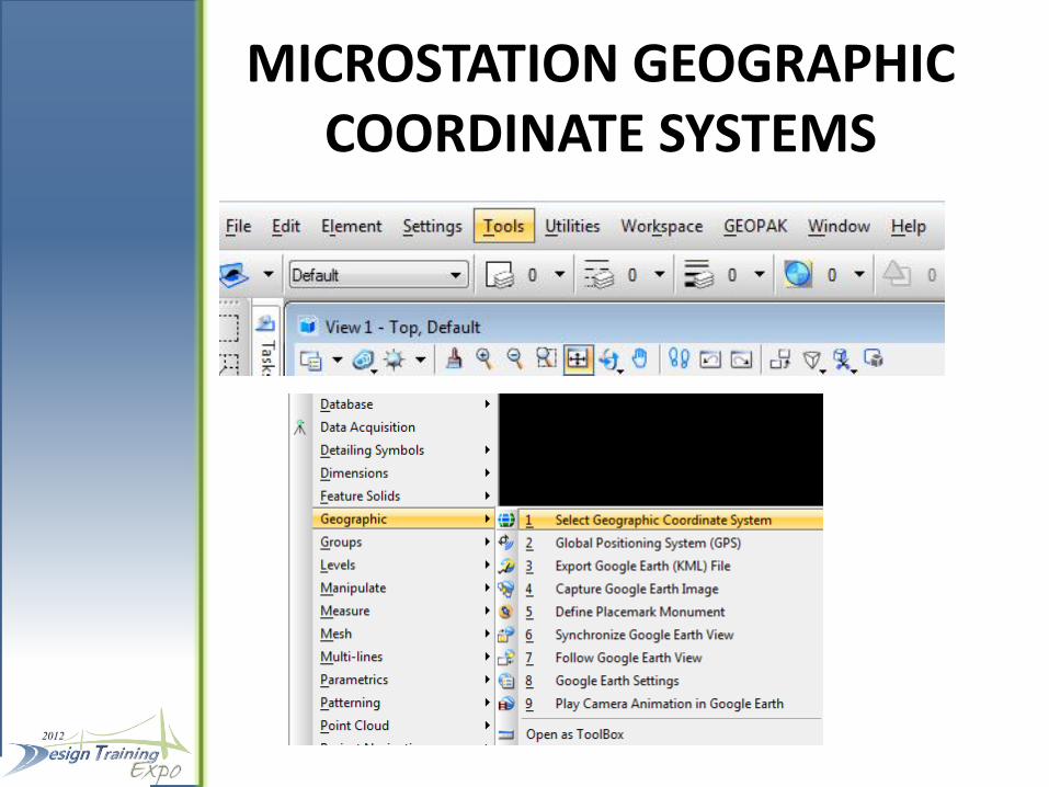
MICROSTATION GEOGRAPHIC COORDINATE SYSTEMS

ACTIVATE DATA ACQUISITION
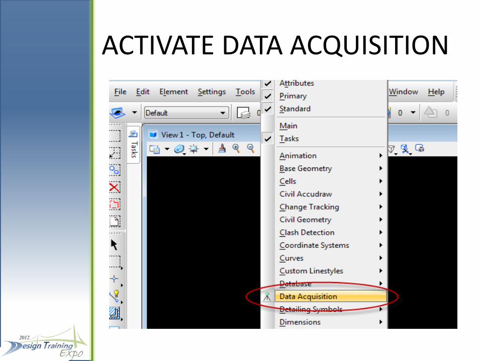
ACTIVATE DATA ACQUISITION
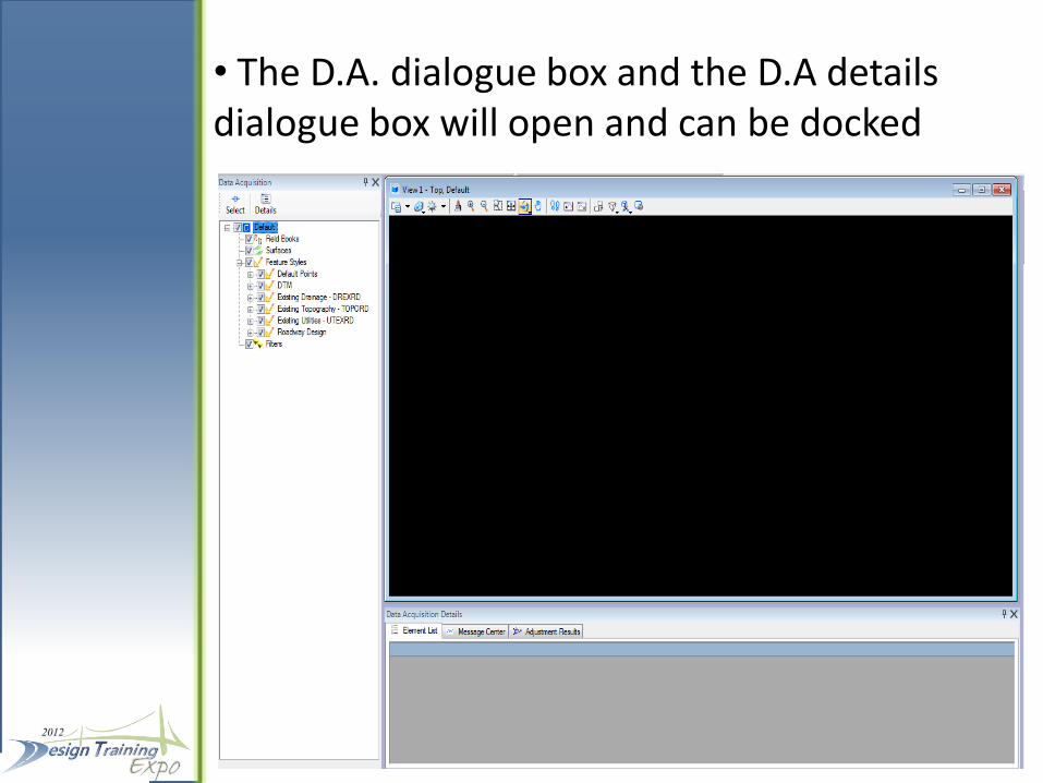
• The D.A. dialogue box and the D.A details dialogue box will open and can be docked
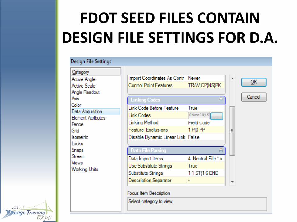
FDOT SEED FILES CONTAIN DESIGN FILE SETTINGS FOR D.A.
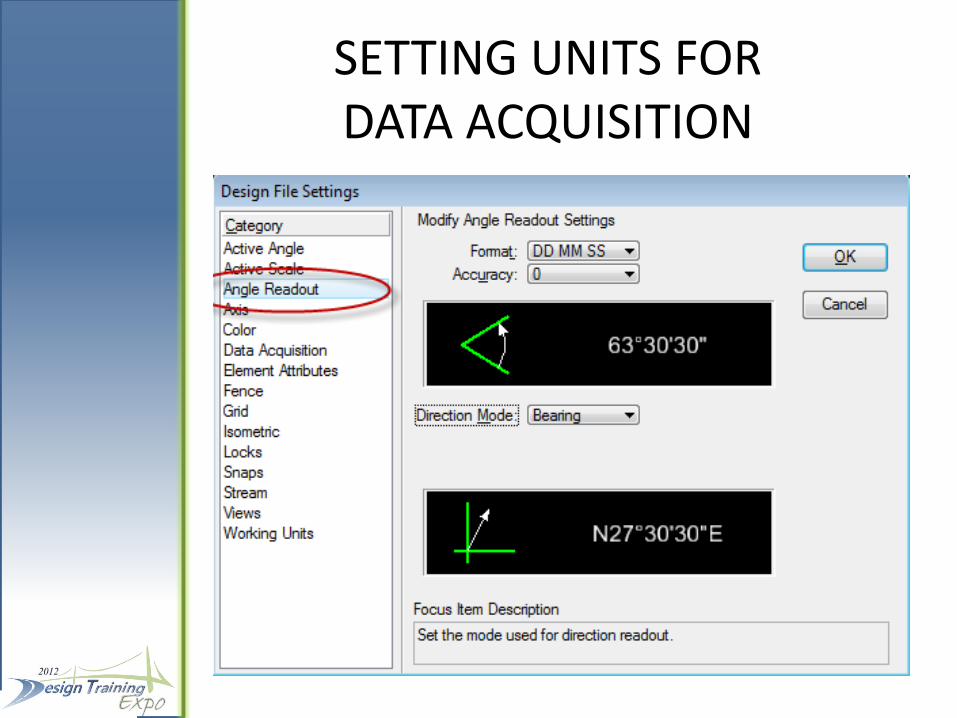
SETTING UNITS FOR DATA ACQUISITION
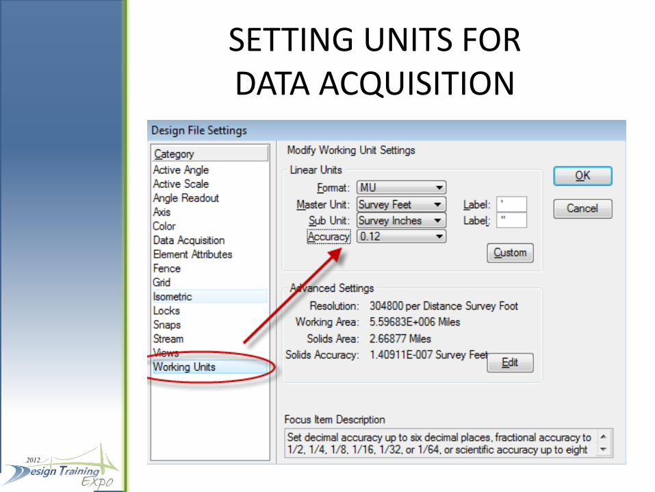
SETTING UNITS FOR DATA ACQUISITION
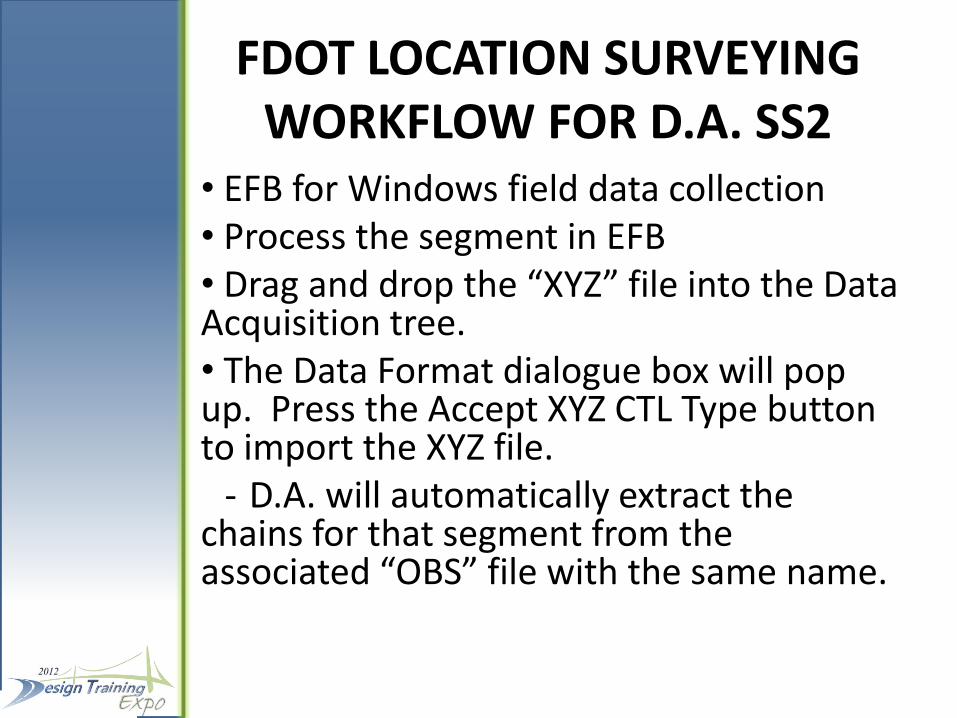
FDOT LOCATION SURVEYING WORKFLOW FOR D.A. SS2
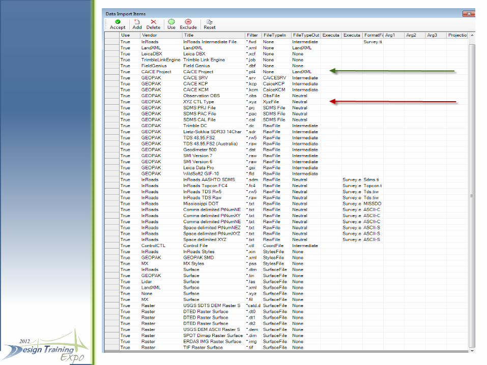
• EFB for Windows field data collection • Process the segment in EFB • Drag and drop the “XYZ” file into the Data Acquisition tree. • The Data Format dialogue box will pop up. Press the Accept XYZ CTL Type button to import the XYZ file. - D.A. will automatically extract the chains for that segment from the associated “OBS” file with the same name.
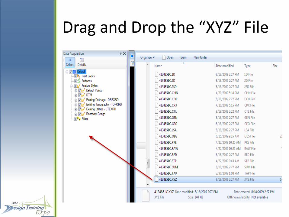
Drag and Drop the “XYZ” File
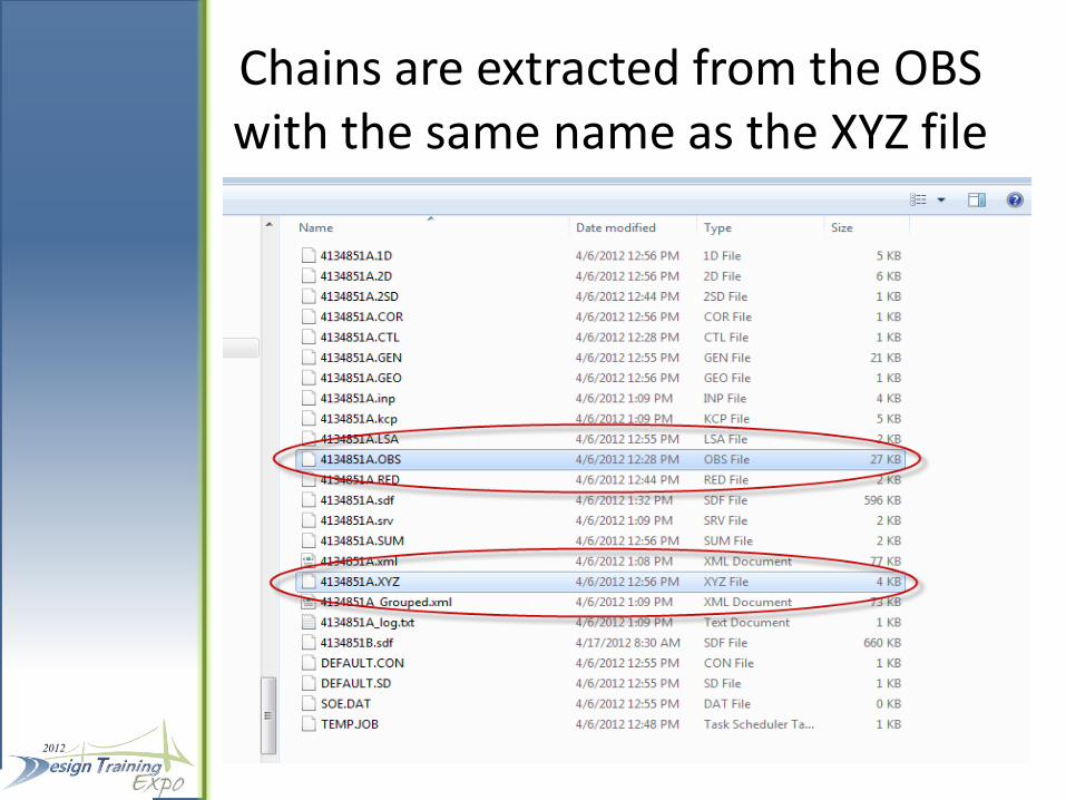
Chains are extracted from the OBS with the same name as the XYZ file
Field Books
• Continue dragging and dropping segments into D.A. until all segments have been added to the field book
• The field book can be renamed from Default 1 to an appropriate name
• Additional field books can be added by right clicking and selecting “New…”
• Data can be added to the “New field book by right clicking on that field book.

POINT SCALES ARE SET BY THE FDOT XML STYLE FILE
• Cells will be brought in at 5 times their original scale (1”=50’).
• Line styles for linear features will be brought in at a 1.00 scale factor.
- To view the line styles at a desired scale from the Models pull down, click on Model Properties and set the line style scale to the desired scale.
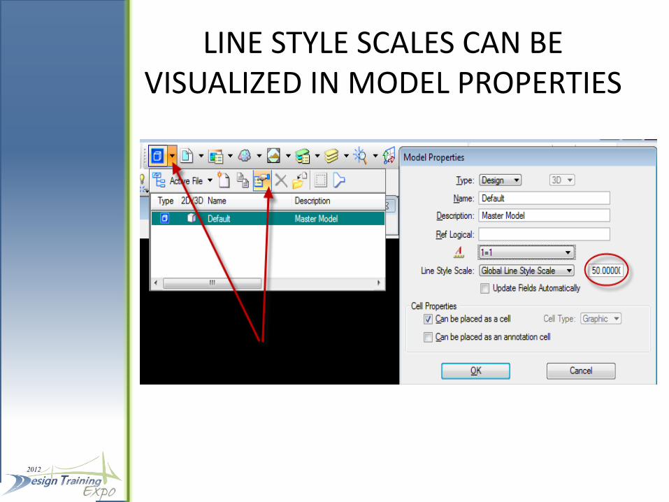
LINE STYLE SCALES CAN BE VISUALIZED IN MODEL PROPERTIES
CHAIN EDITING
• Data Acquisition has tools for building and editing linear features (chains). • Editing the OBS to add or edit collected chains is also an option and provides legacy data that can be used across multiple platforms, including CAiCE and Civil 3D. • For Data Acquisition it is a simple process to delete the field book and re-drag and drop the XYZ segments to visualize the updated chains

CHAIN EDITING
• What is the “Best Practice”?
OBS Editing or D.A. Database Editing?
At this point it is too early to tell. It may depend on the size of the job, the downstream customers’ requirements, or what the surveyor feels is most economical.
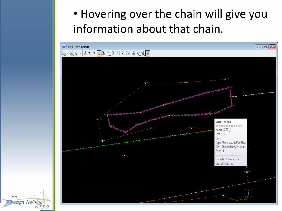
• Hovering over the chain will give you information about that chain.

• Right clicking on the chain will give access to chain editing functionality
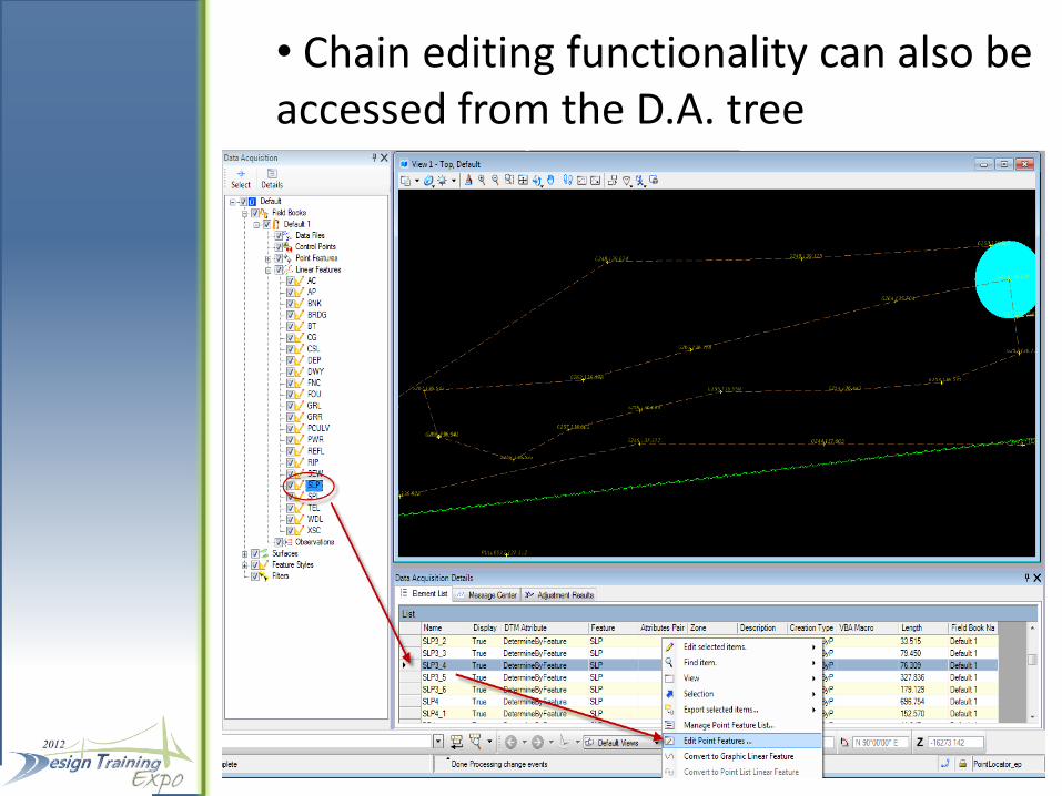
• Chain editing functionality can also be accessed from the D.A. tree
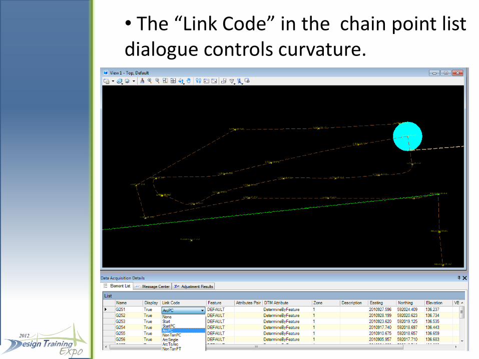
• The “Link Code” in the chain point list dialogue controls curvature.
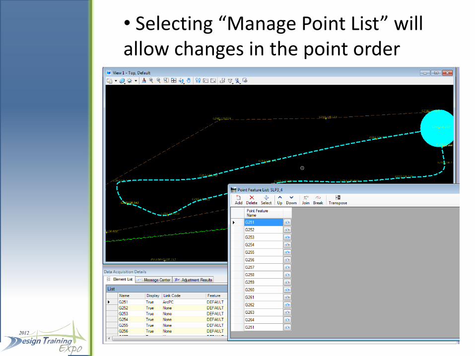
• Selecting “Manage Point List” will allow changes in the point order
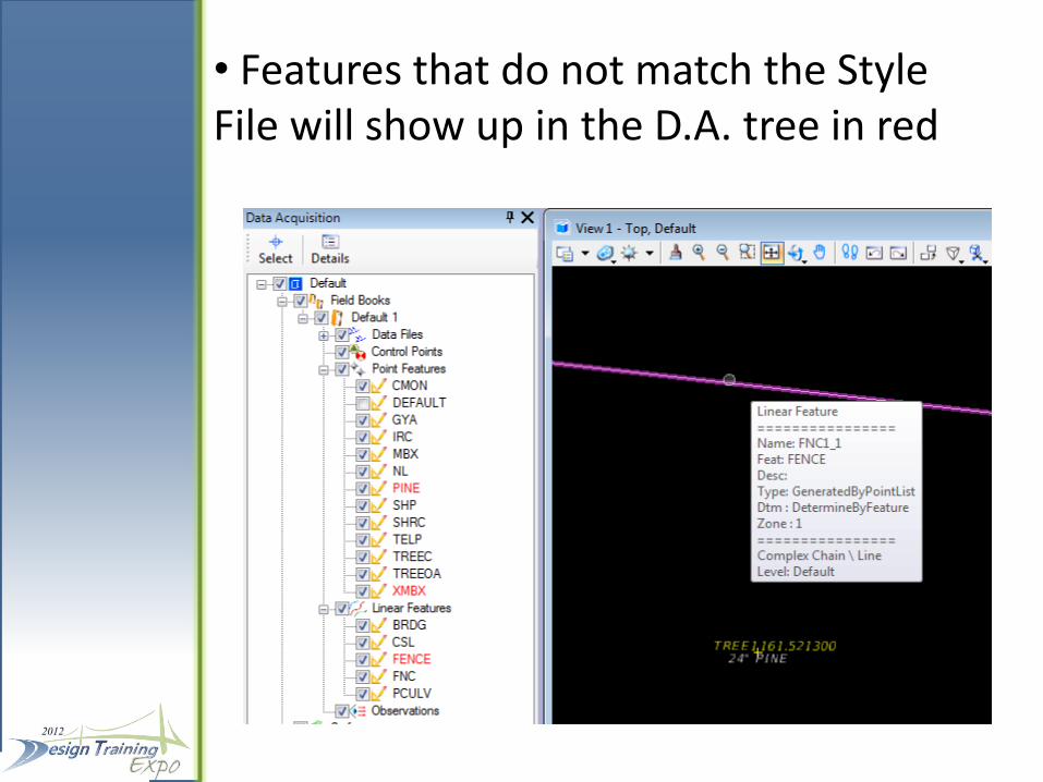
• Features that do not match the Style File will show up in the D.A. tree in red
SURFACES
• Surfaces are created automatically.
• The “All Field Books” surface is created by default. This surface is made up of all data in the database
• Checking the appropriate box in the Surface tree will show the graphics for that attribute
• Right clicking on the Surface will allow the user to export the surface to permanent graphics or a TIN file.

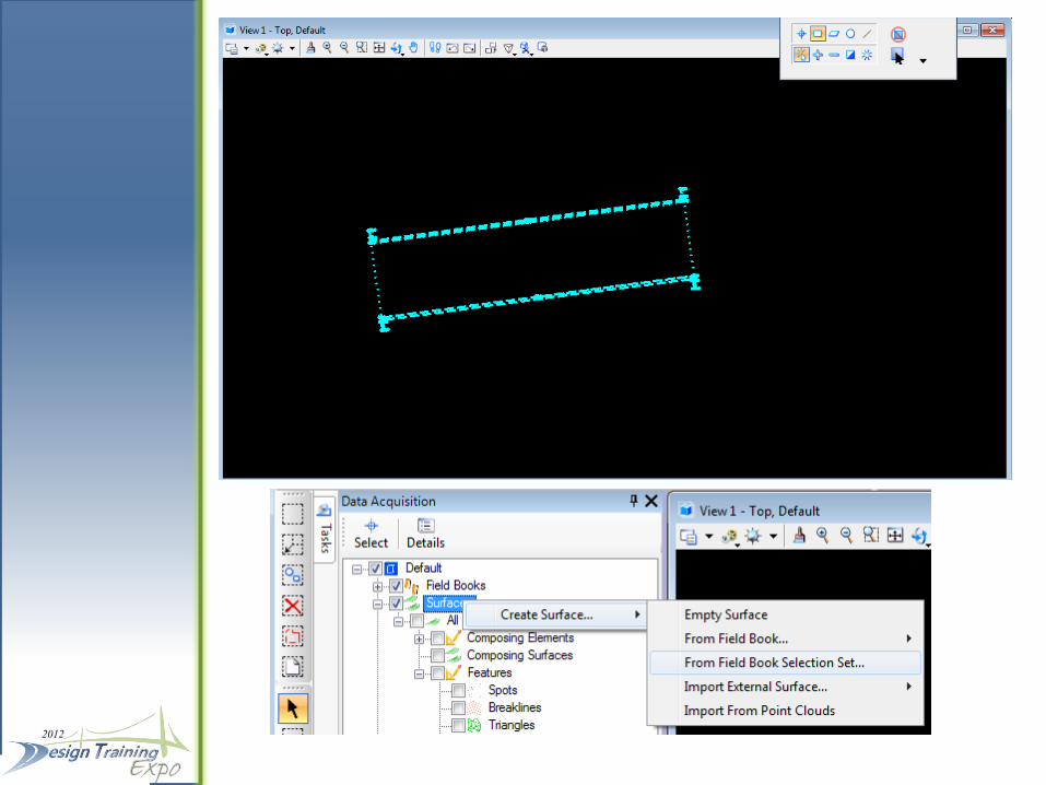
Creating Specific Surfaces
• Right Clicking on Surfaces in the DA tree will allow the user to create a new surface • Creating a surface from a selection set will allow users to create a surface in a specific area from graphical data in the current view • Select the desired data, right click on “Surfaces” and create a surface from the field book selection set • DTM point attributes can be edited by using chain editing functionality
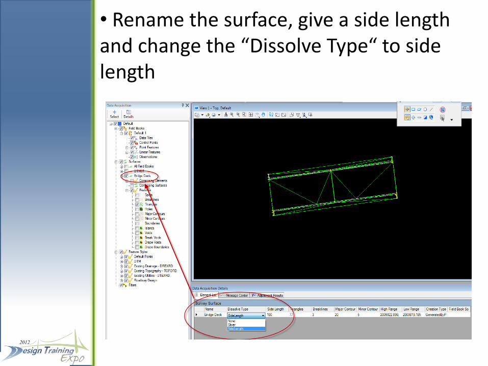
• Rename the surface, give a side length and change the “Dissolve Type“ to side length
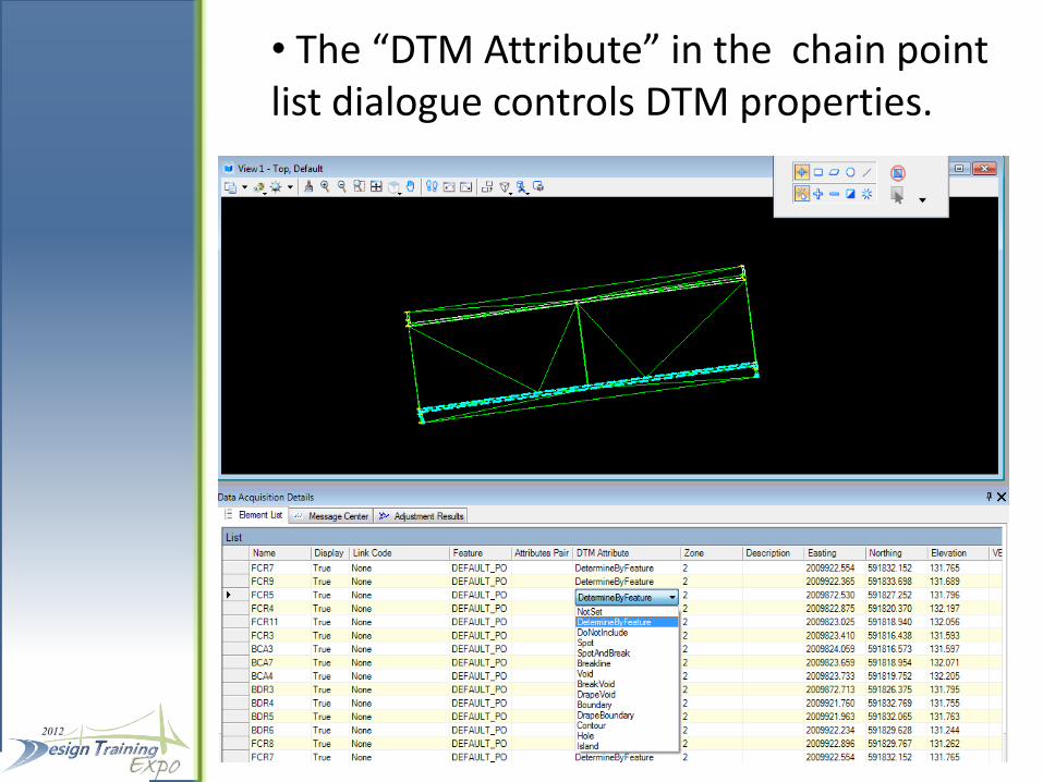
• The “DTM Attribute” in the chain point list dialogue controls DTM properties.
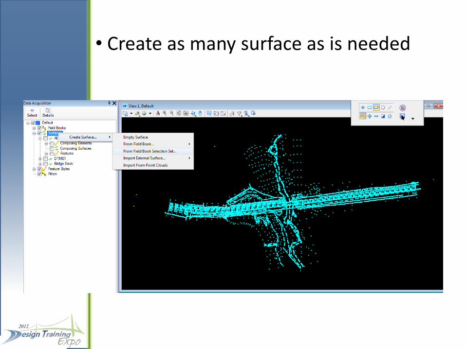
• Create as many surface as is needed
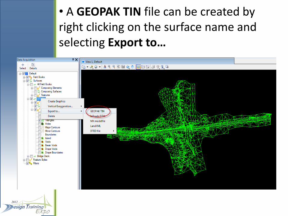
• A GEOPAK TIN file can be created by right clicking on the surface name and selecting Export to…
CREATING FDOT SURVEY DELIVERABLES
• Creating the GDTMRD file can be done using GEOPAK and the TIN file created from D.A.
• Creating the DREXRD, TOPORD, and UTEXRD files can easily be done by “visualizing” the graphics using the feature styles in the D.A. tree
• Check to visualize, uncheck to turn off visualization of groups or individual features
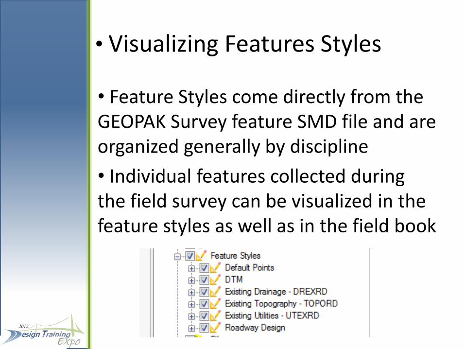
• Visualizing Features Styles
• Feature Styles come directly from the GEOPAK Survey feature SMD file and are organized generally by discipline
• Individual features collected during the field survey can be visualized in the feature styles as well as in the field book
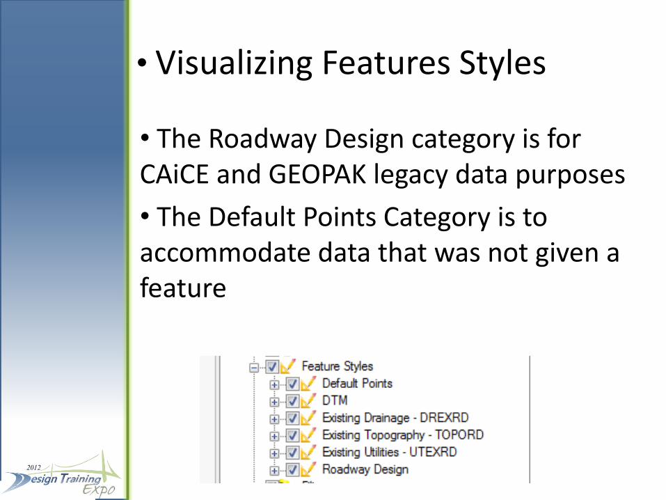
• Visualizing Features Styles
• The Roadway Design category is for CAiCE and GEOPAK legacy data purposes
• The Default Points Category is to accommodate data that was not given a feature
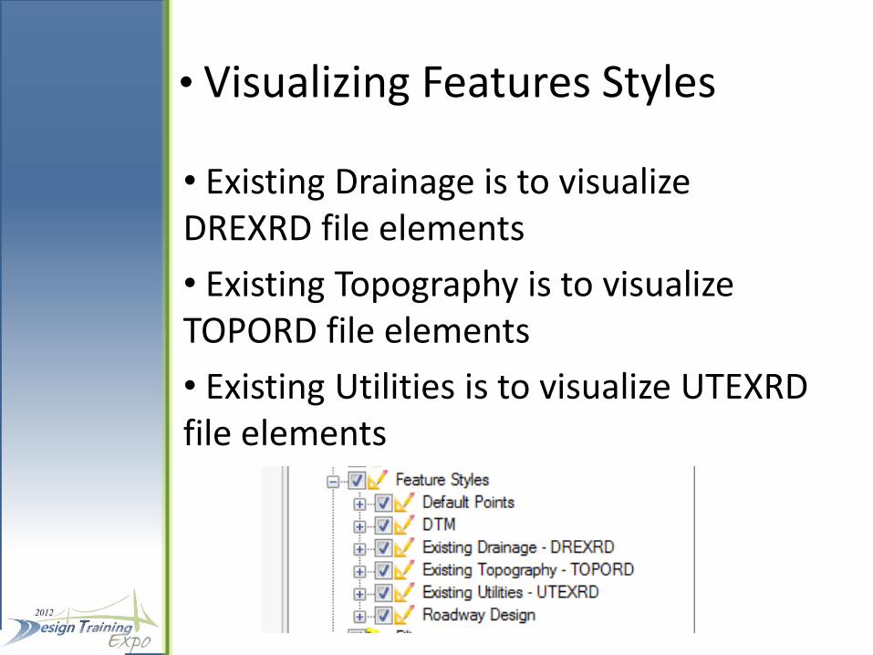
• Visualizing Features Styles
• Existing Drainage is to visualize DREXRD file elements
• Existing Topography is to visualize TOPORD file elements
• Existing Utilities is to visualize UTEXRD file elements
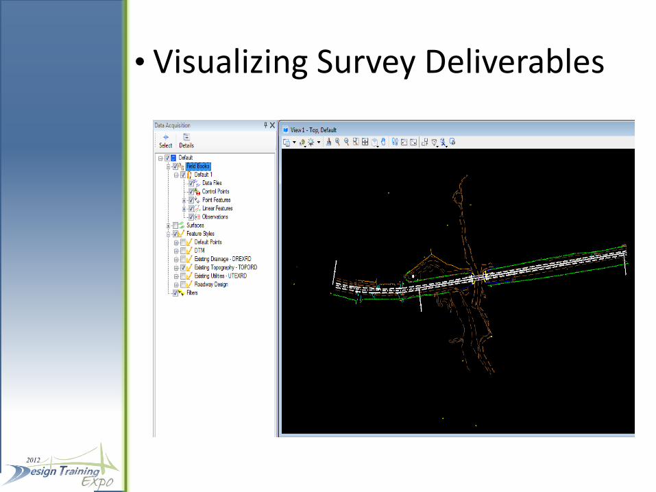
• Visualizing Survey Deliverables
• To visualize the TOPORD elements check the Existing Topography category
• Check any other categories that are desired to be included in the TOPORD
• Uncheck any categories that are not to be included in the deliverable
• The procedure for creating the DREXRD and UTEXRD files is the same
• Visualizing Survey Deliverables
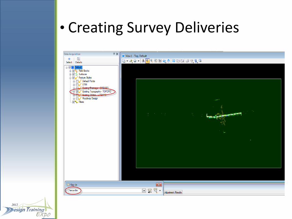
• Creating Survey Deliveries
• To create the TOPORD.dgn file put a fence around the elements in the view
• Type in the Key-in box “fence file” and the windows “Save As” dialogue box will open so a file can be saved
• Type in a file name and press “Open”. The dialogue box will close and then you must click on the view to accept the creation of the file
• Creating Survey Deliveries
• Creating Survey Deliveries
• There is one more step because this is a 3D TOPORD.dgn file
• Close the current Data Acquisition project file and open the new 3D TOPORD.dgn file.
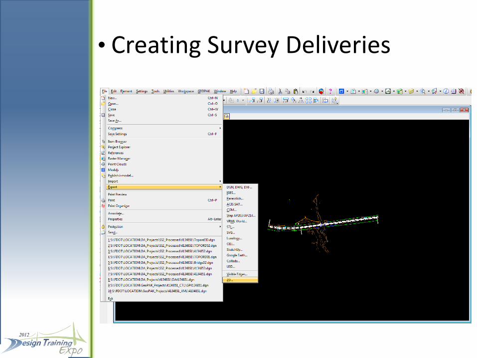
• Click on File>Export>2D… to create the TOPORD01.dgn file
• As in any survey deliverable normal MicroStation editing will be necessary to complete the deliverable for delivery to design
• Creating Survey Deliveries
CREATING FDOT RIGHT OF WAY DELIVERABLES
• In Data Acquisition there is no need to re-import or massage data to go from Surveying deliveries to Right of Way deliveries even though levels, cells, line styles and attributes are significantly different
• Change the FDOT Menu bar configuration from Roadway Design to Right of Way Mapping
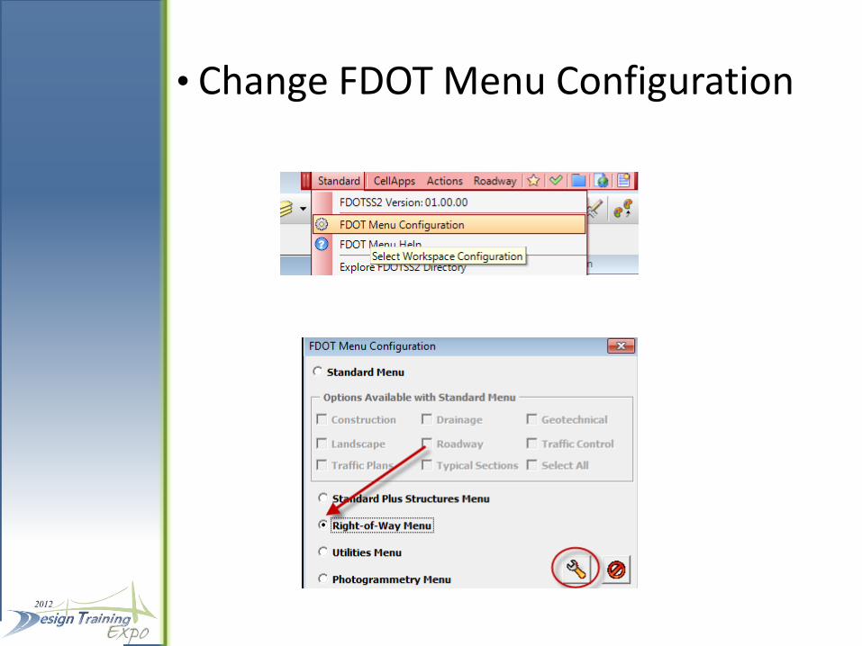
• Change FDOT Menu Configuration
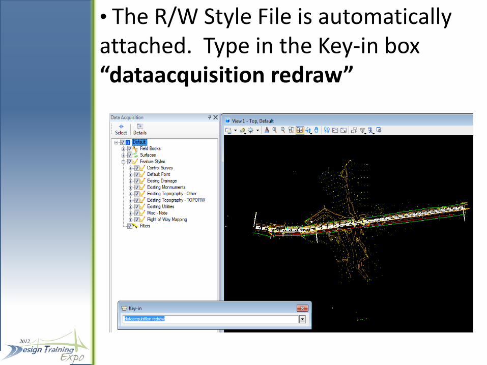
• The R/W Style File is automatically attached. Type in the Key-in box “dataacquisition redraw”
• Creating Right of Way Deliveries
• The “dataaquisition redraw” Key-in will apply the current Style File features • Note the differences are not immediately apparent however, they include: - R/W style monuments - Some cells have a mask - Many of the “dashed” lines for existing point features are now solid lines - Some custom line styles like railroad centerlines are different in right of way
• Creating The TOPORW File
• Note the difference in Categories • The process for creating a TOPORW file is similar to creating the TOPORD file - Check the box for Existing Topography - Check the box for Existing Monuments - All other boxes should be unchecked unless the feature is desired to be included in the TOPORW File • The process for creating the TOPORW deliverable is identical to creating the TOPORD (Use “fence file” and then export to a 2D)
IMPORTING CAiCE PROJECTS
• Data Acquisition will accommodate importing CAiCE projects
- Choose the appropriate configuration (Roadway or Right of Way)
- Choose the appropriate seed file
- Drag and drop the CAiCE PT4 file into Data Acquisition
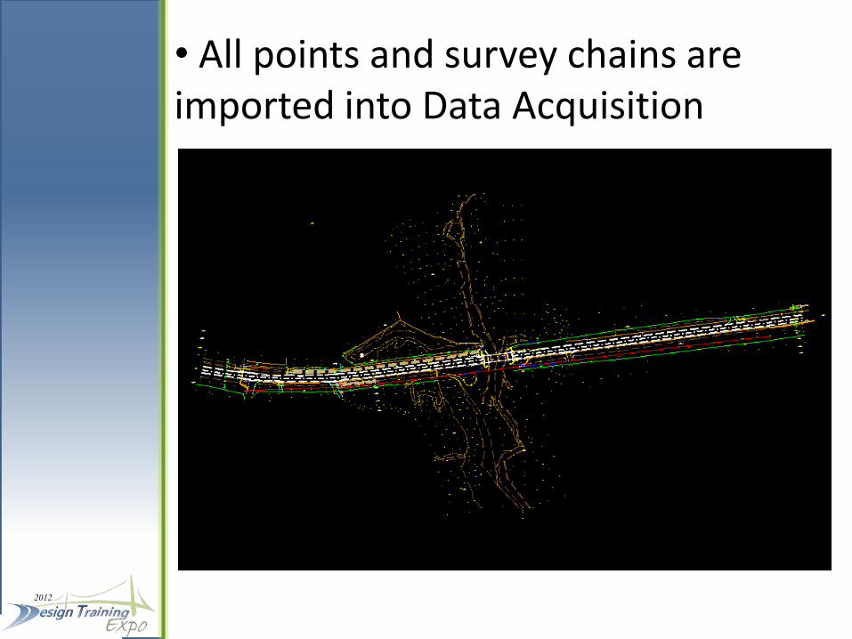
• All points and survey chains are imported into Data Acquisition
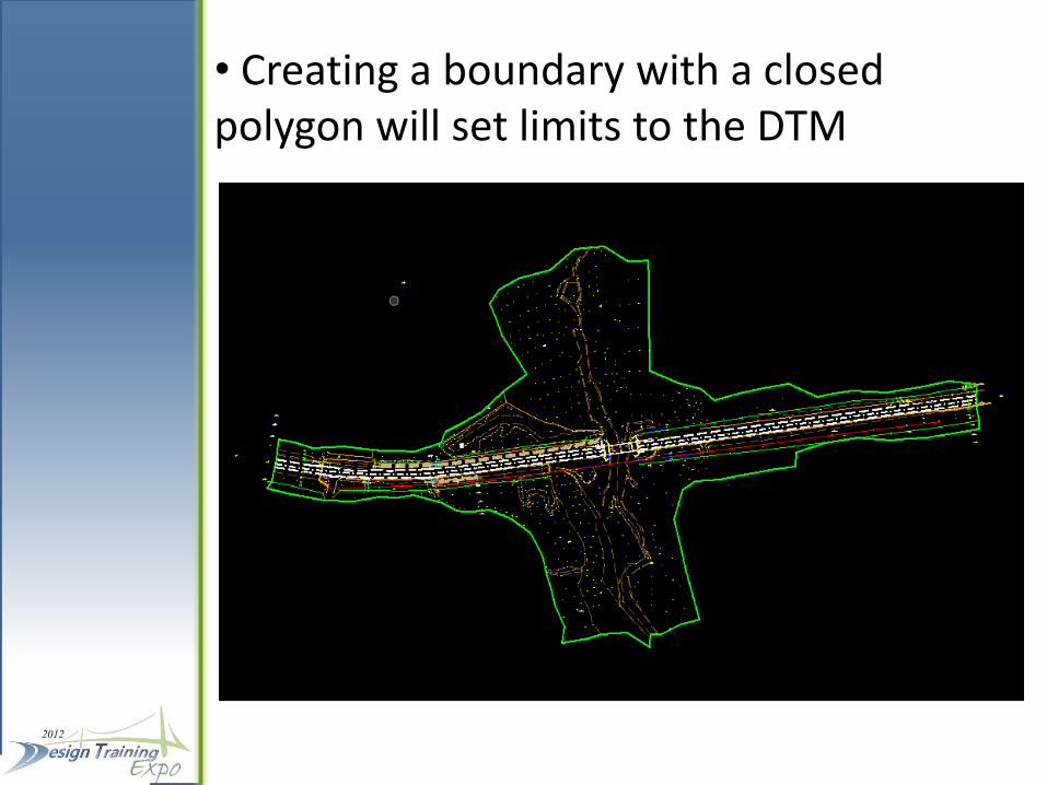
• Creating a boundary with a closed polygon will set limits to the DTM
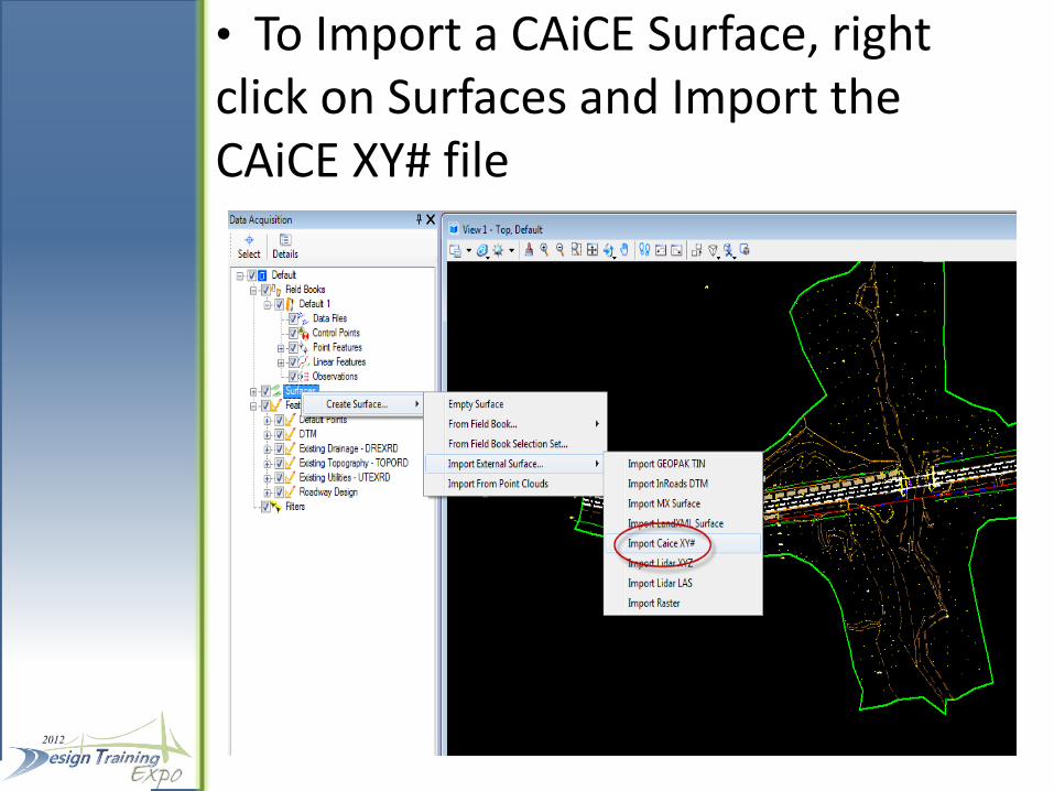
• To Import a CAiCE Surface, right click on Surfaces and Import the CAiCE XY# file
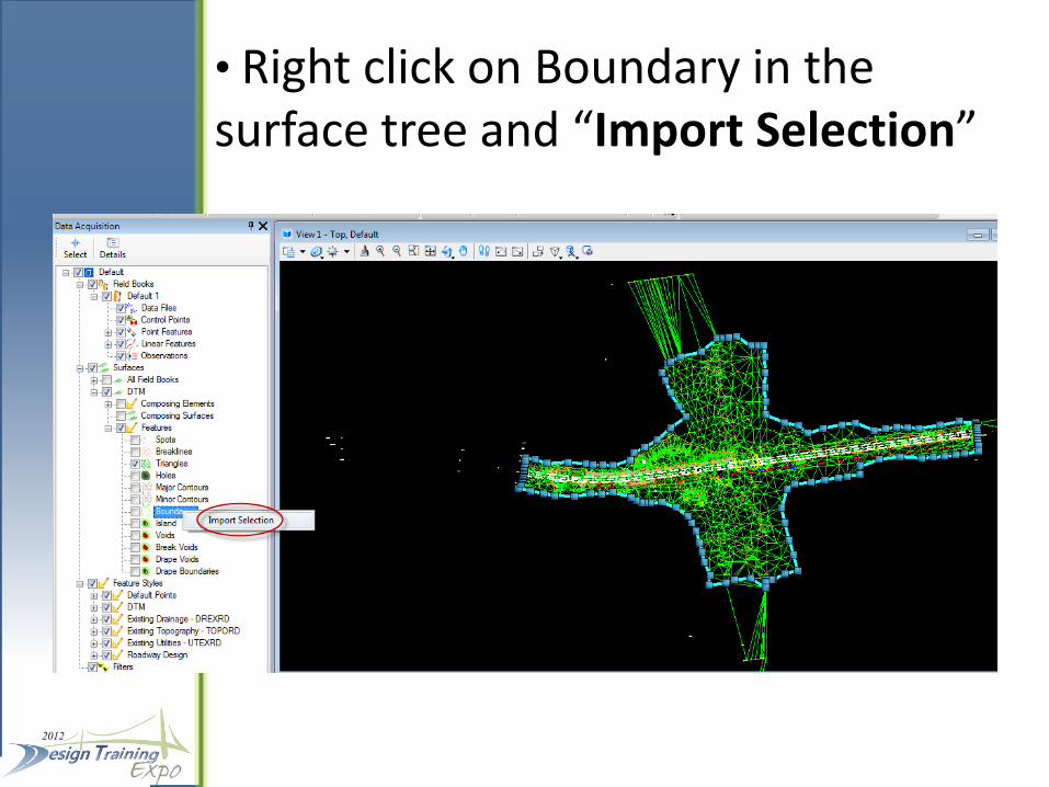
• Right click on Boundary in the surface tree and “Import Selection”
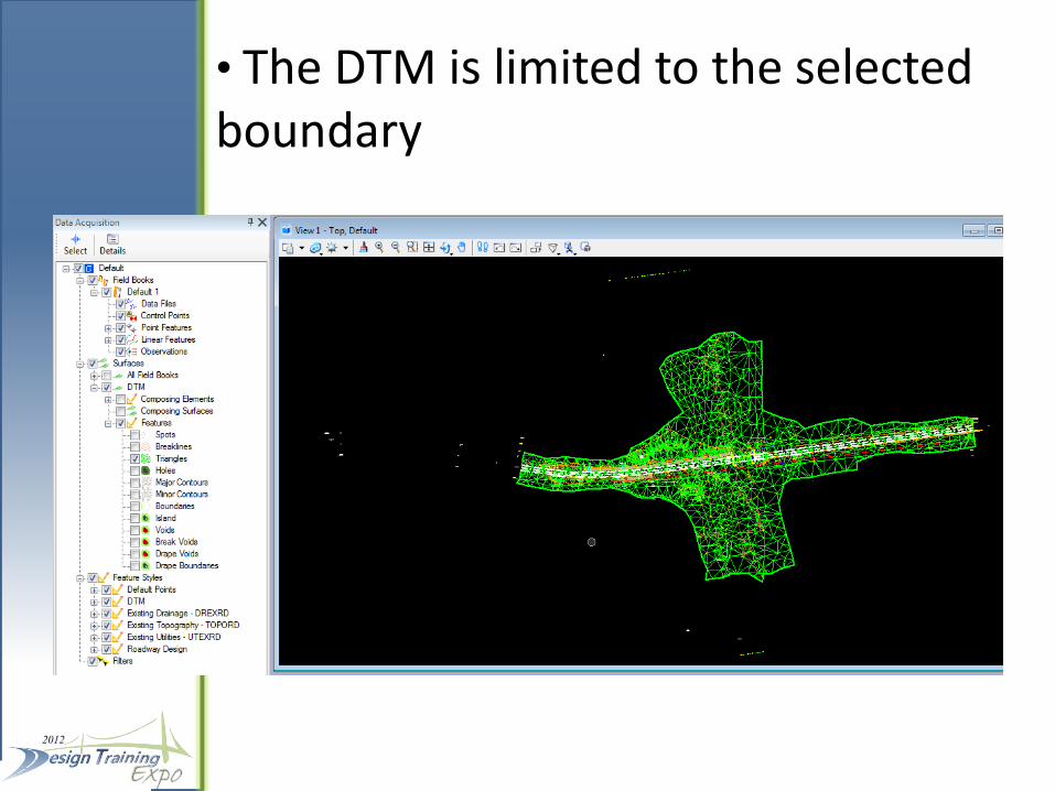
• The DTM is limited to the selected boundary
EXPORTING POINTS AND CHAINS TO GEOPAK
• Data Acquisition is a work in progress
• At some point a left turn must be made and data moved to GEOPAK
• SS3 will have improvements over SS2 and the left turn will be further down the road
• Eventually there may not be a need to use GEOPAK for surveying purposes
• Export Database to GEOPAK File
• Right Click on the Field Book in the D.A. tree and select “Export to>GEOPAK Format”
• The format is a GPK file
• Point and survey chain features along with descriptors will be included

THE END


![[XLS] · Web viewBentley PowerRebar Reinforced Concrete Detailing and Scheduling Bentley PowerSurvey Field-to-Finish Survey Data Management Bentley Rail Track Combining InRail and](https://static.fdocuments.in/doc/165x107/5aed56667f8b9a90318f8c78/xls-viewbentley-powerrebar-reinforced-concrete-detailing-and-scheduling-bentley.jpg)