SURPRISE-1 WELL COMPLETION REPORT -...
25
SURPRISE-1 WELL COMPLETION REPORT (Basic) EP 115 Amadeus Basin Northern Territory 11 th Oct. – 5 th Dec. 2010 Central Petroleum Limited
Transcript of SURPRISE-1 WELL COMPLETION REPORT -...

SURPRISE-1
WELL COMPLETION REPORT
(Basic)
EP 115
Amadeus Basin
Northern Territory
11th
Oct. – 5th
Dec. 2010
Central Petroleum Limited

Surprise-1 Well Completion Report (Basic)
i
Well Name: Surprise-1
Well Classification: Exploration
Interest Holders: Central Petroleum Limited (Operator 100%)
Petroleum License: EP 115, Northern Territory
Location: Northing: 7377073m
Easting: 601261m
Latitude: 23º 42’ 50.758S” South
Longitude: 129º 59’ 36.091”E East
Australian Map Grid Zone : GDA 94, Zone 52
Ground Level (GL): 545m asl
Kelly Bushing (KB): 550.2m asl - Datum
Total Depth (KB): 2555m (interim)
Drilling Contractor: MB Century Drilling
Drilling Rig: Century Drilling Rig 7 (See Rig Specifications in Appendix 8)
Contractors: Drilling Fluids: Australian Mud Company
Mud Logging: Weatherford
Wireline Logging: Weatherford
Cementing: Viking Energy
Earth Works/water carting: BJT Services
Spud Date: 11th
October 2010
Total Depth Reached: 2nd
December 2010
Rig Released: 5th
December 2010
Well Status: Plugged and Suspended.
Surprise-1 Well Completion Report (Basic)
ii
Table of Contents
1.0 Introduction and Summary 4
2.0 General Data 6
3.0 Drilling 7
3.1 Summary of Drilling and Related Operations 7 3.2 Particulars of Drilling 11
3.2.1 Particulars of the equipment installed in or on the well 11 3.2.2 Casing and equipment including details of suspension. 11
3.2.3 Cementing operations 13
3.2.4 Bit Records 13 3.2.5 Deviation Surveys 13 3.2.6 Drilling Fluids 13 3.2.7 Lost Time 14
3.2.8 Water Supply 15
4.0 Logging, Sampling and Testing 16
4.1 Cuttings Samples Inventory 16 4.2 Conventional Cores 16
4.3 Sidewall Cores 16
4.4 Mudlogging 16 4.5 Wireline Logging 16 4.6 Drill Stem Testing 16
5.0 Geology and Formation Evaluation 17
5.1 Regional Geological Setting and Discussion of the Surprise Prospect 17 5.1.1 Structural Elements 17 5.1.2 Lithology and Formation Tops 18
5.1.3 Undifferentiated Recent Alluvium and Pertnjara Group 19 5.1.4 Brewer Conglomerate/Hermannsburg Sandstone 19 5.1.5 Parke Siltstone (mid Devonian) 20
5.1.6 Mereenie Sandstone (early Devonian) 20 5.1.7 Stokes Siltstone (late Ordovician) 20 5.1.8 Upper Stairway Sandstone (Early Ordovician) 21 5.1.9 Middle Stairway Sandstone (Early Ordovician) 21
5.1.10 Lower Stairway Sandstone (E Ordovician) 21
5.2 Hydrocarbon Indications and Sample Analysis 22 5.2.1 Gas while drilling 22 5.2.2 Fluorescent Hydrocarbon Shows 22 5.2.3 Other Indications of Oil 23
6.0 Reference 24

Surprise-1 Well Completion Report (Basic)
iii
Tables Table 1: Surprise-1 Well Index Sheet. ............................................................................. 6
Table 2: Surprise-1 Formation tops, actual and predicted. ............................................ 18
Figures Figure 1: Surprise-1 Location and Permit Map ............................................................... 4
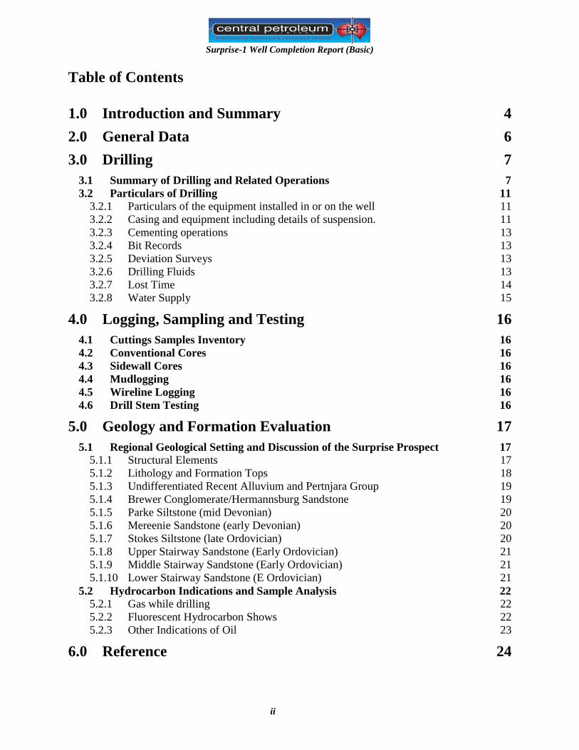
Figure 2: Surprise-1 location map and seismic lines. ...................................................... 5
Figure 3: Surprise-1 Suspension Diagram ..................................................................... 12
Figure 4: Surprise-1 Time breakdown ........................................................................... 14
Figure 5: Amadeus Basin structural elements map ........................................................ 17
Figure 6: Cross Section Surprise-1 to Johnstone West-1 ............................................... 18
Appendices 1. Daily Drilling Reports
2. Daily Geological Reports
3. Cuttings Descriptions & Coring
4. Bit records
5. Survey listing
6. Drilling Fluid Recap, RMS Pty Ltd
7. Mudlogging data
8. Rig Specifications

Surprise-1 Well Completion Report (Basic)
page4of25
1.0 Introduction and Summary
Surprise-1 was drilled by Central Petroleum Ltd in EP-115 in the western part of the Amadeus
Basin, Northern Territory, approximately 400km west of Alice Springs (Figure-1 & -2). The well
was spudded on 11th
October 2010 and reached interim TD of 2555m.
The primary aim of Surprise-1 was to test the hydrocarbon potential of a salt cored anticlinal
structure mapped at the Pacoota and Stairway Sandstones. Secondary objective was to core the
shales of the Horn Valley siltstone, a sequence which separates the Pacooota and Stairway
sandstones, in order to obtain information regarding the potential shale gas in this area.
During drilling good oil shows were encountered in the Lower Stairway Formation and a core
was cut over the interval 2546-2555m. The core recovered 8.38m of fair to good reservoir
quality sandstone with excellent oil shows and free oil.
A wireline formation tester and sampler was run but due to the rig mechanical problems whilst
attempting wireline formation testing the well was terminated, so the Horn Valley siltstone and
the Pacoota sandstone were not penetrated.
On the 2nd
December 2010 the well was halted due to mechanical problem with the rig’s mast
after attempts to rectify the problem failed. The well was plugged and suspended on the 5th
December 2010. Daily drilling and geological reports are provided in Appendices 1 and 2.
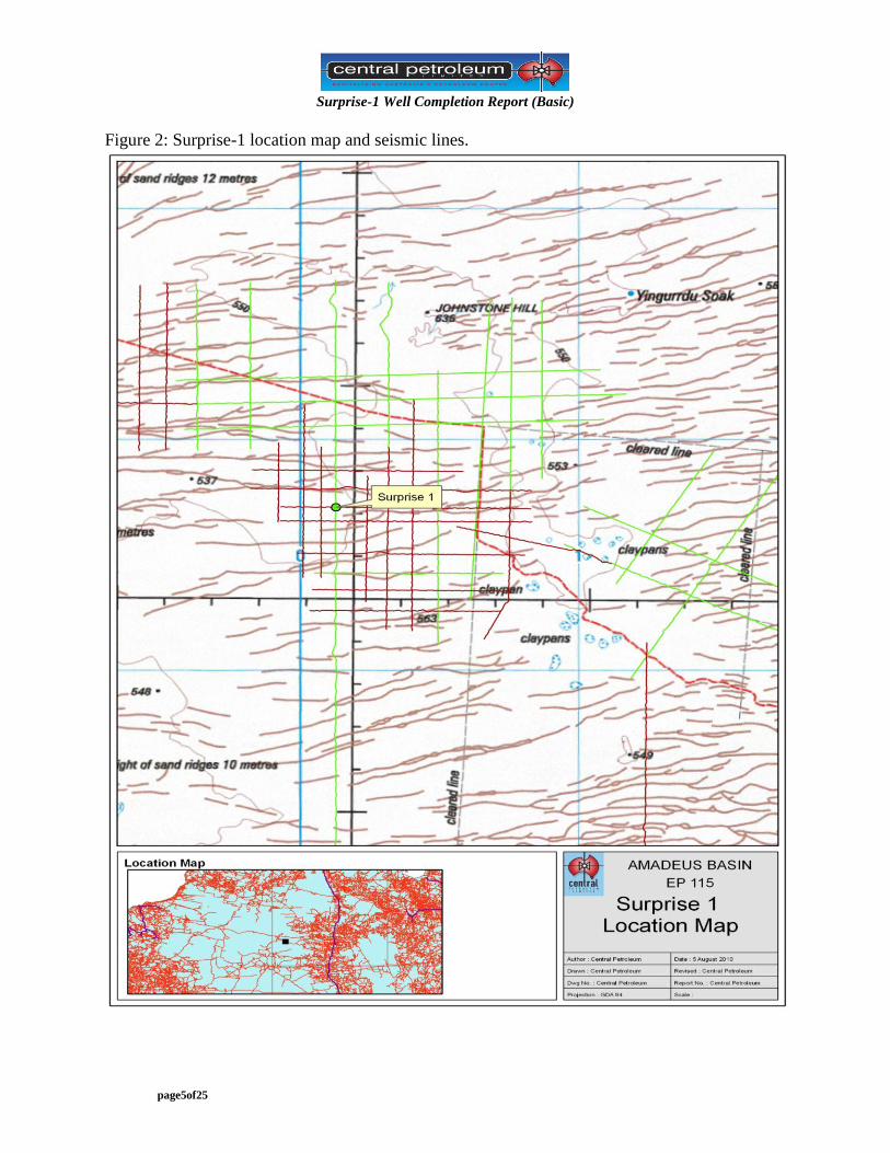
Basic well results are summarised in the Well Index Sheet (Table-1).
Figure 1: Surprise-1 Location and Permit Map
Surprise-1 Well Completion Report (Basic)
page5of25
Figure 2: Surprise-1 location map and seismic lines.
Surprise-1 Well Completion Report (Basic)
page6of25
2.0 General Data
Table 1: Surprise-1 Well Index Sheet.
WELL NAME: Surprise-1
OPERATOR: Central Petroleum Limited CLASSIFICATION : Exploration
Location: Latitude 23º 42’ 50.758”S
Longitude 129º 59’36.091”E
GDA 94 Zone 52
Rig Details:
Rig Name: MB Century Rig 7
Contractor: Century Drilling
Rig Type: land
Dates: Spud Date: 11
th Oct 2010
TD Date: 2nd Dec 2010
Rig Released: 5th
Dec 2010
Basin: Amadeus
Field: Wildcat
Permit: EP 115, Northern
Territory, Australia.
Depths:
Surface Elevation (asl): 545m
Rig Datum, KB: 5.2m agl
Total Depth: 2555m
Status:
Capped and suspended
Casing/Liner Details: Size Depth
20”Conductor 21.3m
13⅜” 493.82m
9⅝” 1443.4m
Mud Details: Mud Type
KCL polymer mud 5.2 - 2555m.
Trajectory: Vertical (3 deg @ TD)
Coring Details: Core#1: 2546.2 - 2555m rec
Sidewall Cores:
No side wall coring was executed Cuttings Interval Sample Rate 23m - 340m 10m
340m - 1300m 5m
1300m - 2546 3m
FORMATION MD
KB (m)
TVD
KB (m)
Isopach
TVD (m)
SubSea
TVD (m)
TWT
msec Comments
Undiff Recent alluvium
Undiff Pertnjara Group
Brewer/Hermannsburg
Parkes Siltstone
Mereenie Sandstone
Stokes Siltstone
Upr Stairway Sandstone
M Stairway Sandstone
Lwr Stairway Sandstone
Total Depth
5.2
70
780
1296
1768
2282
2450
2475
2542
2555
5.2
70
780
1296
1758.5
2271.5
2444.2
2488.0
2539.5
2550
64.8
710
515.6
461.4
513
172.7
43.8
51.5
19
+545.0
+478.7
-231.3
-746.9
-1208.3
-1721.3
-1894.0
-1937.8
-1989.3
-2004.8
Nd* Recent-Quaternary
Mid- Late Devonian
Mid Devonian
E Devonian
Sil-E Devonian
E. Ordovician
E. Ordovician
E Ordovician
E Ordovician
LOGGING
Date Depth (m)
Description Remarks From To
3 Dec 10 2497.2
2475
2498.9
2526
FRT-GR
(gamma interval)
Packer set 2497.2-2498.9m, tool stuck, attempt
fish. Tool retrieved by crane
Rig problems prevented further evaluation by logs
Depth at TD
2555mKB
2550mTVDKB
Latitude
S
Longitude
E
Max deviation 8.5º at 1638m
Azi 89 º
Well Testing: No tests conducted as rig derrick problems caused well to be abandoned before adequate
formation evaluation was possible.
Surprise-1 Well Completion Report (Basic)
page7of25
3.0 Drilling
3.1 Summary of Drilling and Related Operations
The MB Century Rig 7 was rigged up on 11th
October 2010 and the conductor hole was drilled to
7.2m MDRT with a 17 ½” drill bit. The mouse hole and rat hole were drilled and scabbards
installed.
Surprise-1 was spudded at 1130 hours on 11th
October 2010. The 17 ½” insert bit drilled the
conductor hole with the kelly held straight by winch lines to 23m MDRT. Approximately 45
hours were lost while waiting on the 26” hole opener which got significantly delayed. During
this period other rig up operations were completed and equipment for the future BHA’s prepared.
The conductor hole was then opened to 26” with the hole opener which was made up with an 8”
drill collar. This assembly was tripped out and the drill floor was rigged up to run the 20”
conductor pipe.
20” Casing
The 20” 133ppf K-55 LynxSA conductor casing was ran on 14th
October 2010. The casing was
landed on bottom at 21.3m MDRT. 93 sacks of Class G cement was used to cement the
conductor pipe in place.
Drilling 17 ½” Surface Hole
The 17 ½” BHA was picked up with a 9 ½” X-Treme mud motor and a 17 ½” Reed insert bit.
Drilling proceeded to 53m MDRT where a wireline survey was conducted. Drilling continued to
347m MDRT whereby a wireline survey was taken at 164m MDRT & 341m MDRT.
The BHA was tripped out due to the reduced rate of penetration and it was found that the centre
jet was missing. A new 17 ½” Reed mill tooth bit was made up with the same BHA and also an
additional 2 x 8” drill collars were picked up and tripped in. Drilling proceeded to section TD at
499m MDRT whereby a wireline survey was conducted. 50 barrels of high viscosity sweep was
pumped downhole and the 17 ½” BHA was tripped out.
13 3/8” Casing
The 13 3/8” 54.5ppf K-55 BTC surface casing was ran on 19
th October 2010. The casing was
landed on bottom at 493.8m MDRT with the float shoe at 493.5m MDRT and the float collar at
481.9m MDRT.
The surface casing was cemented in place with 194bbls of 12.8ppg lead cement and 98bbls of
15.6ppg tail cement. Cement returns at surface started when they were 151bbls into the
displacement and waited on cement for 5 hours.
The BOP’s were nippled up and pressure tested on 21st October 2010, though there was some
trouble with the BOP leaking.
Surprise-1 Well Completion Report (Basic)
page8of25
Drilling 12 ¼” Intermediate Hole
The 12 ¼” BHA was picked up with the 9 ½” X-Treme mud motor and a 12 ¼” Reed insert bit.
The shoe track was drilled out with 3m of new formation whereby a formation integrity test was
performed. With 8.6ppg water in the hole and a maximum pressure of 1500psi was recorded
without formation breakdown, gives an equivalent mud weight of 26.4ppg.
Drilling proceeded to 667m MDRT whereby a wireline survey was conducted. Drilling
continued to 739m MDRT and the BHA was tripped out for a bit change. A new 12 ¼” Reed
insert bit was picked up with an additional 6 x 6 ½” drill collars. Drilling proceeded to 971m
MDRT whereby a wireline survey was carried out. Drilling then continued to 1,162m MDRT
where the washpipe had to be replaced. The drill string was pulled to the last casing shoe.
The drill string was tripped in again and drilling recommenced to 1,210m MDRT. The drill
string was observed to be turning to the left when the mud pumps were on idle during a
connection. It was decided to trip out the drill string. The mud motor was checked at surface and
it was found that fluid was bypassing the mandrel. The valve on the mud pump, stand pipe, upper
kelly cock, lower kelly cock and full bore stabbing valve were pressure tested.
A new X-Treme mud motor was picked up with a new 12 ¼” Reed insert bit and tripped in.
Drilling proceeded to 1,296m MDRT whereby a wireline survey was taken. Drilling continued to
the section TD 1,447m MDRT whereby another wireline survey was taken. A wiper trip was
conducted to 1,150m MDRT with some tight spot encountered from 1,358m MDRT to 1,320m
MDRT. The drill string was tripped out and laid down.
9 5/8” Casing
The 9 5/8” 47ppf N-80 BTC Intermediate casing was ran on 3
rd November 2010. The casing was
landed on bottom at 1,443.44m MDRT with the float show at 1,442.9m MDRT and float collar at
1,430.9m MDRT.
The intermediate casing was cemented in place with 230bbls of 12.8ppg lead cement and 65bbls
of 15.6ppg tail cement. Bled back 3bbls of cement and waited cement for 6 hours.
The BOPs were nippled up, ‘B’ section installed and BOP was pressure tested. The secondary
seals on the ’B’ section could not be pressure tested as the pressure was not being held.
Drilling 8 ½” Production Hole
The 8 ½” BHA was picked up with the 6 ¾” X-Treme LS mud motor and an 8 ½” Reed PDC bit.
The shoe track was drilled out with 3m of new formation whereby a formation integrity test was
performed. With 9.0ppg mud in the hole and a maximum pressure of 2,497psi was recorded,
gives an equivalent mud weight of 19.9ppg.
Drilling proceeded to 1,658m MDRT whereby a wireline survey was conducted. Decision was
made to pull the bit out of the hole to check it and change the BHA since the inclination was
increasing. The bit was tripped in again with an 8 ½” stabilizer placed above the mud motor.

Surprise-1 Well Completion Report (Basic)
page9of25
Drilling commenced to 1,708m MDRT whereby a wireline survey was taken indicating
decreasing inclination. Drilling continued to 1,739m MDRT whereby another wireline survey
was taken. Another 65m was drilled to 1,804m MDRT whereby a wireline survey was taken
which indicated that inclination had decreasing further. Drilling proceeded to 1,881m MDRT
whereby the drilling assembly was tripped out.
The weekly BOP pressure test was conducted. A new 8 ½” Reed PDC bit was tripped in and
patterned with the downhole motor from 1,881-1,886m MDRT. Drilling proceeded to 2,169m
MDRT whereby 3 wireline surveys had been conducted. The drilling assembly was tripped out
and it was found that the mud motor had a 1 ¼” bearing play/movement.
A new 6 ¾” X-Treme LS mud motor was picked up and made up with an 8 ½” Reed insert bit.
This assembly was tripped in and the interval between 2,156 – 2,169m MDRT was reamed.
Drilling proceeded to 2,220m MDRT whereby the decision was made to trip the drilling
assembly out due to increased and erratic torque.
A new 8 ½” Reed insert bit was made up and tripped in. Drilling commenced to 2,225m MDRT
whereby it was decided to trip out due to low rate of penetration and to change BHA. The mud
motor was broken out and a new BHA was prepared which was subsequently tripped in. Drilling
proceeded to 228.9m MDRT whereby it was decided to trip out to pick up additional drill collars.
The weekly BOP test was conducted with the Viking cementing unit.
The new BHA was tripped in but tight spots were encountered and at one of the spots, the drill
string got stuck. The drilling jars were activated freeing the drill string and the section was
reamed though this did not clear the tight spot. The drill string was tripped out and the near bit
stabilizer was removed. The new drill bit was patterned and drilling proceeded to 2,289m MDRT
whereby a wireline survey was conducted and the drill string tripped out for a bit and BHA
change.
The 6 ¾” XL mud motor was made up with a re-run 8 ½” Reed PDC bit and tripped in. Drilling
proceeded to 2,320m MDRT whereby it was decided to trip out due to low rate of penetration.
The mud motor was laid down and an 8 ½” Halliburton Security insert bit was made up and
tripped in. Drilling continued to 2,546.2m MDRT whereby a drilling break was encountered. A
wiper trip was conducted and the drill string was tripped out to surface.
The weekly BOP pressure test was conducted. The coring assembly was picked up with the 8 ½”
Christensen BHC405 PDC core bit and was tripped in. An 8.8m core was cut from 2,546.m to
2,555m MDRT. The coring assembly was slowly tripped out to last casing shoe and then tripped
out normally to surface. The core was recovered and sectioned at surface. An operational
meeting was held with Central Petroleum management on the forward plan.
It was decided to run the flow rate tester (FRT) tool to procure a downhole sample of oil. The
wireline unit was rigged up and the FRT was calibrated and function tested. The FRT was then
tripped in and correlated to 2,500m MDRT, the first testing zone. The packers were pumped up
Surprise-1 Well Completion Report (Basic)
page10of25
but there was indication that there was a leak. Attempts were made to free the FRT tool to re-seat
it without success.
The wireline equipment and fishing tools were prepared for the FRT fishing operation. The
Weatherford fishing assembly was tripped in to 2,500m MDRT and engaged the FRT tool which
resulted in the loss of communication with the tool. It was suspected that the wireline had
separated from the FRT tool while it was engaged. The tool was then tripped out of the hole
slowly. The FRT too was laid out. It was then evident that the wireline was differentially stuck as
the wireline could not be pulled out of the hole.
In an attempt to use the travelling blocks to pull the stuck wireline, the monkey board and mast
twisted when the guy wires attached to the monkey board was removed to facilitate the removal
of the upper wireline sheave on the 5th
December 2010. Operations were halted immediately; the
guy wires secured to full pipe bins and the mud losses in the well were monitored.
The well was monitored via the trip tank while an investigation was carried out and a forward
plan formulated. 3 cranes from Mt. Isa arrived on site and commenced the removal of the racked
drill pipe in the damaged monkey board. One of the cranes was then used to pull the stuck
wireline free at 15,000 lbs, approximately 83.3% of the cables breaking strain.
The mast was scoped down and prepared for inspection. The choke manifold and BOP were
pressure tested. While the mast was inspected, the well was monitored for losses. It was then
decided to suspend the well and release the rig. An open hole packer and bridge plugs were
mobilized to site by aircraft. However decision was then made to cancel the open hole packer
and set cement plugs in the open hole section and use the bridge plug in the cased hole section.
The crane was used to pick up the drill pipe to be used as a cement stinger. The first cement plug
was set at 2,370m MDRT. This plug consisted of 11.5bbls of 15.8ppg Class G cement. The next
cement plug was set at 1,473m MDRT. This plug consisted of 14.2bbls of 15.8ppg Class G
cement. The cement plug was tagged and the cementing string was pulled out to the surface.
The Halliburton 9 5/8” EZSV bridge plug was made up with the casing collar locator (CCL) and
correlated on depth to 130m MDRT. With the CCL log giving inconclusive data, the assembly
was tripped out to change the CCL sonde. The assembly was tripped in again and the bridge plug
set on depth at 128m MDRT on 18th
December 2010. 7.3bbls of 15.8ppg Class G cement was
dumped on top of the bridge plug. Rig down operations began and the rig was released at 0900
hours on 19th
December 2010.
Surprise-1 was the last of the three wells drilled in the Central Petroleum Limited 2010
Conventional Drilling Campaign.

Surprise-1 Well Completion Report (Basic)
page11of25
3.2 Particulars of Drilling
3.2.1 Particulars of the equipment installed in or on the well
Other than casing, there is no other equipment that is installed in the well.
3.2.2 Casing and equipment including details of suspension.
Conductor Casing
- 20” conductor casing was set at 21.3m MDRT.
Surface Casing
- 13 3/8” surface casing was set at 493.8m MDRT.
Intermediate Casing
- 9 5/8” intermediate casing was set at 1,443.44m MDRT.
Suspension
The well was suspended with the setting of 3 cement plugs (2,310m – 2,360m MDRT, 1,415m –
1,475m MDRT, 100m – 130m MDRT) and a wireline bridge plug at 130m MDRT. 9.0ppg KCl
weighted fluid has been set between the plugs. A suspension flange has also been installed on the
wellhead at surface.

Surprise-1 Well Completion Report (Basic)
page12of25
Figure 3: Surprise-1 Suspension Diagram
Surprise-1 Well Completion Report (Basic)
page13of25
3.2.3 Cementing operations
The following cementing operations were performed:
Conductor Casing – A 26” hole was drilled to 23m MDRT. The 20” 133ppf K-55 BTC
conductor casing was cemented in place with 93 sacks of Class G cement on 14th
October 2010.
Surface Casing – A 17 ½” hole was drilled to 499m MDRT. On 20th
October 2010, the 13 3/8”
54.5ppf K-55 BTC surface casing was cemented in place with 12.8ppg lead cement consisting of
194bbls of Class G cement. This was followed by 98bbls of 15.6ppg tail cement consisting of
Class G cement. The plug was bumped at 420psi. There were 108bbls of cement returns.
Intermediate Casing – A 12 ¼” hole was drilled to 1,447m MDRT. On 4th
November 2010, the 9 5/8” 47ppf N-80 BTC intermediate casing was cemented in place with 12.8ppg lead cement
consisting of 230bbls of Class G cement. This was followed by 61.3bbls of 15.6ppg tail cement
consisting of Class G cement. The plug was bumped at 1,200psi. There were 15bbls of cement
returns.
3.2.4 Bit Records
A record of drilling bits used on Surprise 1 is presented in Appendix 4.
3.2.5 Deviation Surveys
Deviation surveys were taken using a Magnetic Single Shot survey tool. Survey results are
tabulated in Appendix 5. Maximum deviation was 8.5 deg at 1638m.
3.2.6 Drilling Fluids
26” Conductor Hole, 0m – 23m MDRT
Basic Gel Spud Mud
Mud weight was kept at 9.1ppg throughout this section. The mud engineer was not present on
site during this section.
17 ½” Surface Hole, 23 – 499m MDRT
Basic Gel Spud Mud
Mud weight was kept between 9.1 – 9.4ppg to the section TD. The mud engineer arrived on site
when the drilling of this section was underway.
12 ¼” Intermediate Hole, 499m – 1,447m MDRT

Surprise-1 Well Completion Report (Basic)
page14of25
KCl PHPA Mud
Mud weight was kept between 8.6 – 9.2ppg to the section TD.
8 ½” Production Hole, 1,447m – 2,555m MDRT
KCl Polymer Mud (Pac-R)
Mud weight was kept between 8.95 – 9.1ppg to the section TD. The API fluid loss had been
reduced in an attempt to reduce filtrate invasion of the reservoir. During the drilling of this
section, a dumping and diluting regime had to be practiced as solids control efficiency was
reduced without a centrifuge on site. Solids were also pulverized by the drill bit forming
colloidal solids which could only be removed through chemical means reducing the effectiveness
of the centrifuge that was brought in at a later stage.
Further detail on the Drilling Fluid composition, performance and usage can be found in the
Drilling Fluid Recap located in Appendix 6. A detailed daily record of drilling fluid properties
can be found in the daily reports supplied by RMN Pty Ltd within this document.
3.2.7 Lost Time
A total of 433.5 hours were summed as actual lost time. The big items that contributed to the lost
time were the damage of the monkey board and mast amounting to 238 hours. The next big item
would be the time taken to fish out the stuck FRT tool amounting to 57.5 hours. The third big
item would be time taken waiting on the 26” hole opener to arrive on site amounting to 45.5
hours. This is graphically illustrated on the following pie chart.
Figure 4: Surprise-1 Time breakdown
Total Time On Surprise 1
Normal Time
67%
Inefficient Work
1%
Poor Logistics
3%Equipment Problem
3%
Hole Condition
1%
Unplanned Event
25%

Surprise-1 Well Completion Report (Basic)
page15of25
3.2.8 Water Supply
Water for drilling purposes and human consumption was taken from the high flow water bore
past the Surprise 1 lease and the road side bore on the CPL private road, 30km from the Surprise
1 lease. Water from these bores was carted to the turkey’s nest built at the well site where it was
then pumped to the rig to be used as drill water. Water was also pumped to the RO plant at the
camp to be treated for human consumption as the water had a high salt content.
Surprise-1 Well Completion Report (Basic)
page16of25
4.0 Logging, Sampling and Testing
4.1 Cuttings Samples Inventory
Sample type Interval mRT frequency
Washed and air dried 24-340 10m
Washed and air dried 340-1300 5m
Washed and air dried 1300-2546 3m
4.2 Conventional Cores
One conventional core was cut in 8½” hole from 2546.2-2554.4m in aluminium sleeve. Total
recovery was 8.2m. It was cut into 1m lengths at wellsite and chips were taken for eaxamination
each meter. Rubber end plugs were placed on each tube of core and it was shipped to ACS
Laboratories in Brisbane for core analysis, photography and slabbing. The core now resides at
the Central petrleum office in South Perth, WA.
Core photos are included in Appendix 3.
4.3 Sidewall Cores
There were no Sidewall cores taken in Surprise-1
4.4 Mudlogging
Mudlogging services were provided by Weatherford, which included monitoring of drilling
parameters, continuous gas monitoring, pit level sensors and cuttings sampling and bagging. A
mud log was provided at the end of the well, refer to Appendix 7.
4.5 Wireline Logging
No wireline logs were executed in Surprise-1 due to mechanical poblems.
4.6 Drill Stem Testing
No drill stem tests were conducted.
Surprise-1 Well Completion Report (Basic)
page17of25
5.0 Geology and Formation Evaluation
5.1 Regional Geological Setting and Discussion of the Surprise Prospect
5.1.1 Structural Elements
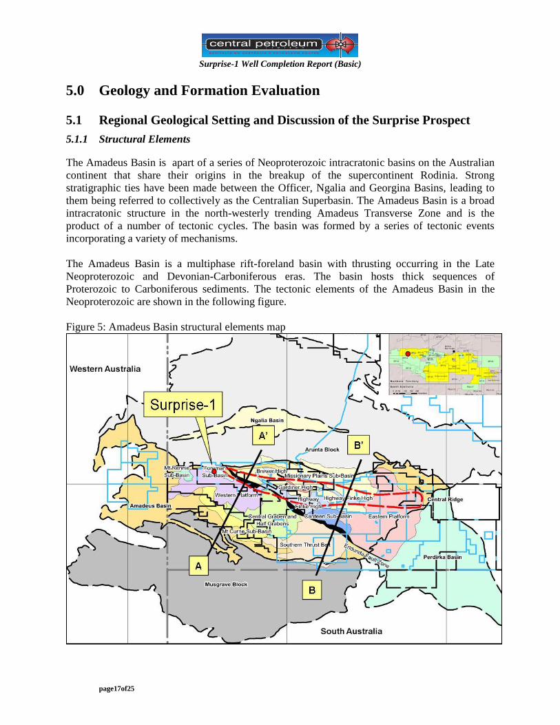
The Amadeus Basin is apart of a series of Neoproterozoic intracratonic basins on the Australian
continent that share their origins in the breakup of the supercontinent Rodinia. Strong
stratigraphic ties have been made between the Officer, Ngalia and Georgina Basins, leading to
them being referred to collectively as the Centralian Superbasin. The Amadeus Basin is a broad
intracratonic structure in the north-westerly trending Amadeus Transverse Zone and is the
product of a number of tectonic cycles. The basin was formed by a series of tectonic events
incorporating a variety of mechanisms.
The Amadeus Basin is a multiphase rift-foreland basin with thrusting occurring in the Late
Neoproterozoic and Devonian-Carboniferous eras. The basin hosts thick sequences of
Proterozoic to Carboniferous sediments. The tectonic elements of the Amadeus Basin in the
Neoproterozoic are shown in the following figure.
Figure 5: Amadeus Basin structural elements map
Surprise-1 Well Completion Report (Basic)
page18of25
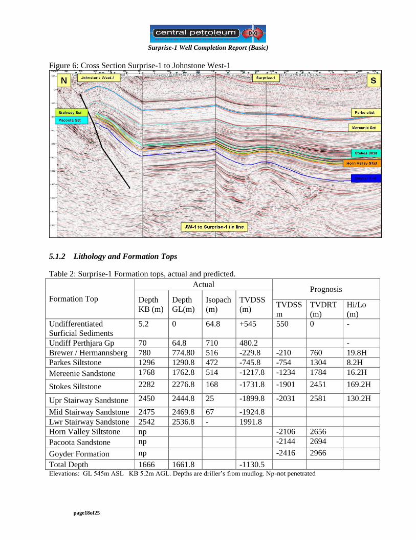
Figure 6: Cross Section Surprise-1 to Johnstone West-1
5.1.2 Lithology and Formation Tops
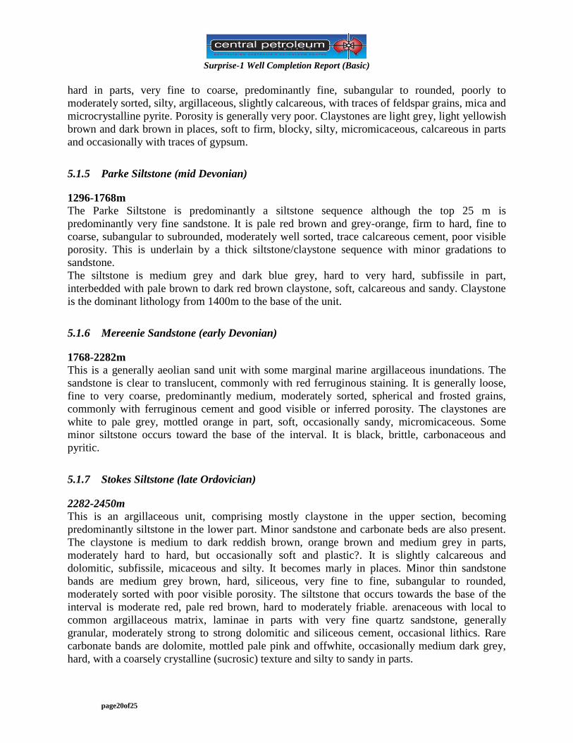
Table 2: Surprise-1 Formation tops, actual and predicted.
Formation Top
Actual Prognosis
Depth
KB (m)
Depth
GL(m)
Isopach
(m)
TVDSS
(m) TVDSS
m
TVDRT
(m)
Hi/Lo
(m)
Undifferentiated
Surficial Sediments
5.2 0 64.8 +545 550 0 -
Undiff Perthjara Gp 70 64.8 710 480.2 -
Brewer / Hermannsberg 780 774.80 516 -229.8 -210 760 19.8H
Parkes Siltstone 1296 1290.8 472 -745.8 -754 1304 8.2H
Mereenie Sandstone 1768 1762.8 514 -1217.8 -1234 1784 16.2H
Stokes Siltstone 2282 2276.8 168 -1731.8 -1901 2451 169.2H
Upr Stairway Sandstone 2450 2444.8 25 -1899.8 -2031 2581 130.2H
Mid Stairway Sandstone 2475 2469.8 67 -1924.8
Lwr Stairway Sandstone 2542 2536.8 - 1991.8
Horn Valley Siltstone np -2106 2656
Pacoota Sandstone np -2144 2694
Goyder Formation np -2416 2966
Total Depth 1666 1661.8 -1130.5 Elevations: GL 545m ASL KB 5.2m AGL. Depths are driller’s from mudlog. Np-not penetrated

Surprise-1 Well Completion Report (Basic)
page19of25
5.1.3 Undifferentiated Recent Alluvium and Pertnjara Group
5.2-70m
This section comprised aeolian alluvium down to 70m. This is essentially the Quaternary to
Recent dune deposits seen at surface, comprising white to light grey quartz grains stained
yellow-orange and common reworked grey brown siltstone grains. The grains are fine to coarse
and rounded, subspherical and frosted. There are abundant composite grains of quartz sand and
siltstone grains weakly bound with yellow-orange iron oxide cement. Many grains are irregular
and broken indicating it is possibly pebbly. Gypsum appeared in the form of white to offwhite,
chalky, soft material. It is occasionally micro to coarsely crystalline and abundant in parts,
commonly with a vuggy porosity possibly after halite crystals. it is probably distributed as
nodular clumps, and often exposed at the surface in that manner.
70-230m
Firm bedrock was observed at 70m in the form of weathered arkosic sandstone. It is white to
light grey, dark brown grey where silty and argillaceous, friable to firm, fine to coarse,
subangular to subrounded, moderately sorted, with occasional pebbly conglomeratic lags. It is
slightly calcareous and carbonaceous with common kaolin and mica flakes and lithic grains.
Porosity is poor to fair. This is variably interbedded with claystone and siltstone and becomes
predominantly interbedded sandstone and siltstone with depth.
The claystone is medium red brown, mottled greenish grey in parts, soft to firm, blocky, silty and
micaceous. The siltstone is similar being medium to dark red brown, soft, blocky to subfissile,
very argillaeous and very micaceous.
230-780m
This is predominantly a siltstone sequence with various thin interbeds of sandstone, claystone
and gypsum.
The siltstone is medium grey brown to dark grey, soft to hard, generally blocky, argillaceous and
sandy, grading to very fine sandstone in parts. It is micaceous and occasionally gypsiferous with
occasionally carbonaceous laminae and coarse sandy laminatione.
Sandstone is generally light brown to light grey with clear to translucent white quartz grains,
loose to friable, fine to very coarse, predominantly medium grained, subangular to rounded and
poorly sorted. Grains are commonly frosted. It is slightly calcareous, with argillaceous and silty
matrix, traces of mica and traces of crystalline pyrite. Porosity is generally poor. The claystone is
light to medium grey, soft, blocky, silty, micromicaceous with traces of carbonaceous specks.
Gypsum occurs as white chalky nodular material and coarsely crystalline fibrous material.
5.1.4 Brewer Conglomerate/Hermannsburg Sandstone
780-1296m
This section is stratigraphically part of the Pertnjara Group and is essentially similar to the
overlying units. It comprises predominantly siltstone with thin sandstone and claystone interbeds
and intergradations and minor limestone interbeds. The siltstone is medium brown to dark grey
brown, firm to hard, blocky, argillaceous, sandy, slightly calcareous with common dark mica
flakes. Sandstones are light grey green and dark brown, translucent in parts, loose to friable and
Surprise-1 Well Completion Report (Basic)
page20of25
hard in parts, very fine to coarse, predominantly fine, subangular to rounded, poorly to
moderately sorted, silty, argillaceous, slightly calcareous, with traces of feldspar grains, mica and
microcrystalline pyrite. Porosity is generally very poor. Claystones are light grey, light yellowish
brown and dark brown in places, soft to firm, blocky, silty, micromicaceous, calcareous in parts
and occasionally with traces of gypsum.
5.1.5 Parke Siltstone (mid Devonian)
1296-1768m
The Parke Siltstone is predominantly a siltstone sequence although the top 25 m is
predominantly very fine sandstone. It is pale red brown and grey-orange, firm to hard, fine to
coarse, subangular to subrounded, moderately well sorted, trace calcareous cement, poor visible
porosity. This is underlain by a thick siltstone/claystone sequence with minor gradations to
sandstone.
The siltstone is medium grey and dark blue grey, hard to very hard, subfissile in part,
interbedded with pale brown to dark red brown claystone, soft, calcareous and sandy. Claystone
is the dominant lithology from 1400m to the base of the unit.
5.1.6 Mereenie Sandstone (early Devonian)
1768-2282m
This is a generally aeolian sand unit with some marginal marine argillaceous inundations. The
sandstone is clear to translucent, commonly with red ferruginous staining. It is generally loose,
fine to very coarse, predominantly medium, moderately sorted, spherical and frosted grains,
commonly with ferruginous cement and good visible or inferred porosity. The claystones are
white to pale grey, mottled orange in part, soft, occasionally sandy, micromicaceous. Some
minor siltstone occurs toward the base of the interval. It is black, brittle, carbonaceous and
pyritic.
5.1.7 Stokes Siltstone (late Ordovician)
2282-2450m
This is an argillaceous unit, comprising mostly claystone in the upper section, becoming
predominantly siltstone in the lower part. Minor sandstone and carbonate beds are also present.
The claystone is medium to dark reddish brown, orange brown and medium grey in parts,
moderately hard to hard, but occasionally soft and plastic?. It is slightly calcareous and
dolomitic, subfissile, micaceous and silty. It becomes marly in places. Minor thin sandstone
bands are medium grey brown, hard, siliceous, very fine to fine, subangular to rounded,
moderately sorted with poor visible porosity. The siltstone that occurs towards the base of the
interval is moderate red, pale red brown, hard to moderately friable. arenaceous with local to
common argillaceous matrix, laminae in parts with very fine quartz sandstone, generally
granular, moderately strong to strong dolomitic and siliceous cement, occasional lithics. Rare
carbonate bands are dolomite, mottled pale pink and offwhite, occasionally medium dark grey,
hard, with a coarsely crystalline (sucrosic) texture and silty to sandy in parts.
Surprise-1 Well Completion Report (Basic)
page21of25
5.1.8 Upper Stairway Sandstone (Early Ordovician)
2450-2475m
This unit is a sandstone with interbedded siltstone claystone, dolomite and limestone. A good gas
show with a weak oil show was observed in the lower sandy unit of this sequence.
The Upper sandstone unit is patchy pale pink with clear to translucent grains, also light to
medium grey and dark reddish brown and hard. It is generally very fine to fine with some
medium, angular to subrounded, moderately sorted, silica cemented, minor silt, trace lithic grains
with poor visible porosity. This is in turn underlain by a dolomitic sandstone with dolomite
bands. The dolomitic sandstone is offwhite to pale grey, red brown in parts, hard, very fine
grained, angular to subrounded, well sorted, with strong dolomitic cement and poor visible
porosity. The middle unit of this formation is mostly siltstone and claystone interbeds. The
siltstone is described as being moderate red brown, medium grey, firm to brittle, argillaceous and
occasionally sandy, subfissile, slightly dolomitic. The claystone is medium to dark grey,
commonly red brown, moderately hard, silty to sandy, trace micromicaceous, slightly dolomitic.
The basal 10m of this unit is sandy and contains gas and displays oil fluorescence. The sandstone
is clear to translucent, light grey to pale brown, moderately hard, very fine to coarse,
predominantly fine, angular to subrounded, poor to moderate sorting, strong calcareous and
siliceous cement, slightly dolomitic, with common interstitial brown bitumen grain coatings
which were fluorescent.
5.1.9 Middle Stairway Sandstone (Early Ordovician)
2475-2542m
This unit comprises siltstone and sandstone interbeds and seems to provide an effective seal to
the hydrocarbons contained in the lower Stairway sands underlying. The siltstone is dark grey,
blocky to laminated (with fine sandstone), hard, siliceous, argillaceous, micaceous, trace pyrite
and dolomitic. The sandstones are pale to medium grey, friable to hard, very fine to fine, angular
to subrounded, well sorted, variable dolomitic cement, silty, trace pyrite, poor visible porosity.
Traces of hydrocarbon fluorescence were observed.
5.1.10 Lower Stairway Sandstone (E Ordovician)
2542-2555m
The unit is composed of sandstone. Excellent oil shows prompted a decision to core from
2542m. Full recovery was obtained. The sandstone above the cored interval is clear to
translucent and pale grey, friable to hard, fine to very coarse, angular to rounded, poorly sorted,
well cemented with silica, trace pyrite, poor to good visible porosity. Good oil shows were
observed and free oil was noted in the mud and petroliferous odour noted in the cuttings.
Note: Core was cut from 2546.2m to 2555m (driller’s depth), however the core in the laboratory
was marked from 2542 to 2554.8m.
Surprise-1 Well Completion Report (Basic)
page22of25
The core was described from chip samples tsaken at 1m intervals. It was 100% sandstone, clear
to translucent with pale brown patches and commonly light to medium grey. It is fine to very
coarse, predominantly medium grained, angular to subrounded, poorly to moderately well sorted,
generally very strong siliceous cement (quartz overgrowths), thin carbonaceous wavy laminae
indicative of bioturbation is evident, with micro pyrite in parts, common mica flakes, occasional
shale clasts, trace bituminous material, fair to good visual porosity. Good fluorescent shows were
described with weak to strong petroliferous odour. An oil sample of approximately 1 litre was
collected from the triptank after coring and a “small muddy oil sample was taken from the core
trays” (possibly from interval 2551-2554m…daily report 2 Dec 2010).
5.2 Hydrocarbon Indications and Sample Analysis
5.2.1 Gas while drilling
Background gas was generally low comprising C1 only from surface to 2480mKB.Background
gas was noted to rise steadily from this point and heavier components (up to C5+) were
observed. Gas peaks were also noted over the interval 2493-2502m in sandstones accompanied
by fluorescence in sandstones from 2497m. Components up to C5+ were recorded and it was
described as a good gas and oil show. Background gas then remained low until the Lower
Stairway Sandstone was intersected at 2542m. Gas then increased from 3 to 15 units with a peak
at 2546.2m of 20 units, C1-C5+. The drill string was then pulled and coring commenced from
2546.2-2555m.
5.2.2 Fluorescent Hydrocarbon Shows
Fluorescence was first reported in cuttings from 2493m. However no solvent cut was observed
and it was probably related to carbonate mineral fluorescence. Substantial fluorescence was then
repored from 2499-2503m where it was 100% dull to occasionally moderately bright yellow,
patchy to spotted, slow streaming pale blue cut, thin pale blue residue film. This was rated as a
fair show.
The following interval, 2,503.0-2,506.0m, displayed 40% dull to occasionally moderately patchy
to spotted bright yellow with slow streaming pale blue cut and thin pale blue residue film. This
was rated as poor show.
In the interval 2,506.0-2,509.0m, 100%, dull to occasionally moderately bright yellow, patchy to
spotted fluorescence was noted with a slow streaming to weak diffuse pale blue cut, thin pale
blue residue film in sandstone with generally poor to tight porosity. It was estimated to be a poor
to fair show. Fluorecence decreased to 10% with weak cut in the interval 2509-2512m and was a
poor show. Susequent samples to 2525m showed only traces of fluorescence.
At 2542m, a drilling break was accompanied by increased background gas and hydrocarbon
fluorescence. The fluorescence was initially 50% then 100%, dull to occasional moderately
bright yellow, patchy to even, occasionally spotted, slow blooming to weak diffuse pale blue
direct and crush cut (some samples had no direct cut), thin pale blue ring residue. This was a fair
show. From 2,544.5-2,546.2m, 70-100% as above but gradually diminished to dull and very dull
yellow, weak direct and crush cuts - a poor to fair show.

Surprise-1 Well Completion Report (Basic)
page23of25
Coring then proceeded below 2542m and incomplete cuttings were obtained during coring.
Examination of core chip samples indicted two zones of potential oil filled fractures from 2,547.
-2,550.0m and 2,551.0-2554.0m. Both zones had multiple core break points. Bioturbation
(irregular horizons) was tentatively identified.The lower zone had prominent break lines along
these possible irregualg bedding planes.
5.2.3 Other Indications of Oil
The upper part of the core had lighter, brown oil coatings and lower zone black, more viscous oil
coatings on core surface and in broken core gaps. The coring engineer interpreted fractured core
zones similar to other drilled fracture zones where the core broke down hole. Core was coated in
light brown oil from 2,547.0-2,550.0m and with black sticky oil in the slightly deeper zone from
2,551.0-2,554.0m).

Surprise-1 Well Completion Report (Basic)
page24of25
6.0 Reference