Surplus Radio Conversion Manual Vol3
89
$I]HPTI]$ COTI/TR$ION VOLUME III Conversion of 701-A AN/APN.I AN,/CRG7 AN/URg' ATA BC-442, 4s3-4s5, 456-459, ó03 696, 950, t0ó6, 1253 cBY -29125, 50083, 501 41, 52208-1r, 52232, 52302-09 ÍT-2414 (for crystol filter) SEE TABLE OF CONTENTS ON PAGE 4 For Amqfeur, Novice, Technieisn qnd Cifizen's Rqdio Service BADIO I[ANt]AT MBF (COL-430ó5) MD-7i ARC-5 R.9/APN.4 R23-R28/ARC-s RAT, RAV RM-s2 (53) RT-I9/ARC-4 scR-274N scR-522 T-t5/ARC-s to T-23,zARC-5 [, _**
-
Upload
ygiannarakis -
Category
Documents
-
view
142 -
download
11
Transcript of Surplus Radio Conversion Manual Vol3

$I]HPTI]$COTI/TR$ION
VOLUME I I I
Conversion of
701-AAN/APN.IAN,/CRG7AN/URg'ATABC-442, 4s3-4s5, 456-459, ó03
696, 950, t0ó6, 1253cBY -29125, 50083, 501 41,
52208-1r, 52232, 52302-09ÍT-2414 (for crystol filter)
SEE TABLE OF CONTENTS ON PAGE 4
For
Amqfeur, Novice, Technieisn
qnd
Cifizen's Rqdio Service
BADIOI[ANt]AT
MBF (COL-430ó5)
MD-7 i ARC-5
R.9 /APN.4
R23-R28/ARC-s
RAT, RAV
RM-s2 (53)
RT-I9/ARC-4
scR-274N
scR-522T-t5/ARC-s to T-23,zARC-5
[ , _ * *

Just like Ol' LIan Rioer swphrs equipment keeps rolling along. Thesupplv \\'axes and wanes, but never completely dries up. Untold amountsof equipment are snapped up by
"surplus hounds" only to be replaced by
new, larger amounts of equipment arriving from unknown locations. Surelythere must be some huge, hidden factory turling out tons of surplusequipment each day which will be sold to hams and others at bargainprices!
Nfodifying surplus equipment to fit the needs of the Amateur orCitizen Radio fan is interesting and exciting work. The high quality ofmost surplus equipment cannot be matched by commercial equipmentselling at many times the cost of the surplus item. The converted surplusitem can be made a piece of high-grade "ham" equipment at a moneysaving price!
However, every silver lining has a cloud. Some pieces of surplus
equipment do not have schematic diagrams. lv{anv items are modified from
the original diagram, making the conversion process akin to a crossword
puzzle. Other items are not worth the time to convert them! The enthusiast"surplus hound" must choose rvisely and well when he buys, and must be
adept at improvisation and "make-do."
Because of the time required to enter into personal correspondence,
and because of the rapid and chaotic changes in the surplus market (and
surplus equipment ) it is impossible for the editors of this Manual to answer
questions relating to conversions of equipment, to requests for schematics,
or for purchasing information. The reader is referred to CQ magazine,
which runs a surplus column. This column often contains answers to the
perplexing questions which may confront the "surplus hound,"
Good luck, and may youl conversions always workl
Special thanks are due the Arrow Sales Company, North Hollywood,
California for the use of several difficult-to-locate schematics.

q ,? 5n
Cot . No . EE-333
S U R P T U S
CONYERSION
RADIO
MAN UAtl t lVOLUME
W I L L I A M I . O R R
Editor
Copyr igh t , l9ó0 by
Ed i fo rs ond Eng ineers , l td .New Augusto , Ind iqno
Copyr igh t under Pon-Amer icon Convent ion
All rights teserved
Printed in U.S.A,
Published ond distributed to the electronics trode by
New Augus to , l nd iono

SURPLUS RADIO CONVERSION MANUAL
VOLUME I I I
L I S T O F
on which doto is
E Q U I P M E N Tgiven in this volume
Tronsmit ters/Receivers 5 snd 4l
T-15 to T-22IARC-5 )BC-45ó ro 459 & ó9ó (SCR-274N series ICBY-52000 series ,
DY-8 or DY-2A/ARR-2DM.34DBC-4538C-455BC-ó03 (SCR-508, 528, 538)AN/APN- IAN/CRC-7AN/URC-4 (RT- t 59)MD-7lARC-5BC-442RM-52, 53FT.24IAT-23lARC-5BC-458 (SCR-274N)
wE-70r-ABC-l 253BC-r 066R-9/APN-4MBF/COL-430ó5
R-28/ARC-5RT-1 9/ARC-4BC-624 (SCR-522)
BC-312 seriesBC-342 seriesBC-348 seriesBC-375/BC- l 9 lAN/ART.I3LMAN/APT.5cPR-4óACJ (ASB-5)
DynomotorsDynomotors
ReceiverReceiver for Citizens' ServiceReceiver for Ci t izens' Service -- - - - - - - - .
Al t imeter, os Trqnsmit ter - . - - - - . - . - - - - - - . - -
Tronsmit fer / Receiver
Tronsmit ter /Receiver os Hondie-Tolk ie - . - , - - . . - . - - - . - . - , . -
ModulotorReloy for ontennd chonqeoverTelephone Uni t os phone potch
Crystals to moke crystol filter
Tronsmit ter , to 50 or 144 Mc.
Tronsmit fer . conversion to S.S.B.
W. E . Te t rode Tube - . . . - - . . . . - -
Tronsmit ter qs rodio contro l receiver - - . - - . . . . . - - . - . - . - . - . - - -
ReceiverReceiverTronsmit ter , /Receiver - . - . - - - . - .24-vol t Dynomotors to I l5 v.o.c, notors - . - . - . - . - " . . - . . - . -
Receiver, Adding Vor ioble Tuning Control
Receiver/Tronsmit"ter for 2 meters
Tronsmitter,Receivers ---
TVI-proofed
t tt 31 41 7t 8l 922282930303 l3 l374243434646494952ó063
ReceiversReceiversAs ModulotorAutotune Tronsmit terPower Supply for LM Frequency Meter . - . - - . - . - - . - . . . . - - . -
Rodor Set schemot ic d iogromReceiver schemot ic d iogrom
BC-659 Receiver/Tronsmif ter schemct ic d iogrom
BC-I335A Receiver/Tronsmit te: schemot ic díogrom
AN/ARR-2 Receiver schemot ic d icArom
AN/APA-I0 Ponoromic Adopter schemot ic d iogrom
AN/APT-2 Rodsr Set schemot ic d iogrom
Other Outstanding Books from the sqme Publisher
Tnn Reoro Haxosoox
Tnn RelrorELEpHoNE LrcnNsr MeNuer,
Sunpr,us Ranro CoNvsnsroN MeNuel, Vor,uun I
Sunpr,us Reuro CoNvnnsroN MeNuer,, Vor,urte II
THn Wonr-o's RADIo Tusns (BneNs'Rerro TusB Vens Mrcurr)
Tnr Wonr-u's Tnr-nvrsroN Tusns ( BntNs' Tnr-evrsroN Tunrs Veln Mncuv )
Tun Wonr.r's Egurver,rrvr Tunrs ( BneNs' Equrv,l;,nNrs TuBE Venn Macuu )
636769707677788082858688

Sunpr-us Raoro CoNvrnsroN N{eNuel, Voruvn III
The "Commond" Sets
The "Commirnd" Sets are probirblv the rnost popu-
lar pieces of radio equipment on the surplus market.Designed in 1938, they r.vere produced in prodigiouscluantities for over a decade for the Annr', the Naw.nnd the Air Force. The virrious items oî eqr,ip*"t ithat make up ir complete set form ii multi-cliannel ra-dio transmitting nnd receiving pircktrge for use onirirplirnes equipped .w'ith a 21 volt d.c. pos'er solìr.ce.Thc e<Sripment is desígned to transmii irncl reccivevoice, tone rnodultrted, or continnous \\-A\.e siqnals.Incluclcd in the equipment rrre various rec,eir.ers, triuts-rnittcrs, modulators, and auxil iarv items, tabulirted iniigure l.
The basic circuit for i i l l Commirnd transmitte.rs isshorvn in figure 2. A master oscillat<>r erc.ites ir ltrrirof beam power amplif ier tubes connected in p,uJlel.The master oscil lator and pou'er amplif icr ttrning ca-pacitors are ganged for simplif ication of controls .{t lututz cn'stal resonrrtor (Y-50 ) is srrpplit ' t l rr. ith t 'aclrtransmitter for use u'ith a "rnirqic
eve" ttrbe to checkfrer lue.ncv cal i l t ra t ion r r t ( r r ì r s7rr r f op t l r t , c l ia l . T l recrr,strrl cloes not control transntitter fre.<1uenct.. Con-tinuotislv viuiable couplinq brtu'een the pos-er am-plifer t i ink c,ircuit lncl the .urtcnnl c.ircuit is ircli ievedbv ir rotarv lotrcling c'oil i L-51 ) ;rnd a rotan. l ink coilin t l ie arnpl i f ier t iu ik c i rcu i t .
The b:rsic circuit for the Con-rmand receir.ers isshown in figure 3. All receivers are one-band super-l'reterodvnes, and except for L-C elements forrning ther,f. and i.f. tuned cilcuits, they are essentially alikeelectrically and physically. Eacli receiver employs sixmetal 12 volt tubes.
All Command equipment is designed to mount inracks rvhich rnake electrical interconnections via built-in plugs. In general, the racks for one series of equip-ment are not interchangeable u'ith racks of other se-ries, as the plug sizes and pin connections differ forthe different brirnches of tlie Armed Forces. The useof tlie racks is not necessitn', hou'ever, for amateurservice.
The follorving information conccrns the adaptationof the Command equipmcnt for amateur use. Arldi-t ionol conuarsion infornratíon for this Ttoptúar cquip-ment is giuen inVolumes I ancl lI of this surplus con-uersion scríes. The mtrterial ilcluded hereu'itli is nerv,and does not duplicate material given in the previousmanuals.
Conver t ing the Commond Receiverto Six Meters
Technicitrns and v.h.f. operators are interested ina metliod of convcrting the Command rcceivers forv.l i.f. operation. The coiversjon involves constructingiì porver suppll', reu'inding the receiverr coils, and re-placing n tube. This conversion may be done u-ith anyreceivor, but t l ie use of the 3-6 \Ic. r 'cct,iver is recom-mended as the i,f. bandrvidth is about optimum forgeneral usage.
. Remove the top covers and the bottom plate, sav-ing the scre\4/s, Clean off the rear area of tlie receiveru'here the dynamotor rvas mounted and wire in thepo\\,er supplv shou,n in ficure 4. Note that the trvofilament rvindings of the transformer must be correct_ly pliased to produce 11.6 volts, a.c. The 12 volt tubesoperate perfectly at this voltage. N{ake sure the re_ceiver works on a.c. before you start the rest of thisconversion.
Norv, remove the coils by taking out the screws oneach side of the receiver case that hold the assemblv.Lift out the triple coil can and r.emove the t2 ,"r"*,liolcling the coils in the cans. Remove the coils fromthc base and clean the terminals. Discard the orisinalcoils. Wind the self-supporting coils shorvn in fúure5. Reasser"nble the coils in the shields and replace-theLrnit in the recciver.
\e.xt. remove the 12SK7 r.f. tube (immediatelylrcli incl thc tur.rinq capacitor.) and replace it rvith a\\ 'E-717.\, rn'rri lable at anv laree strrplls store. (Thisttrbe is rrn oc,tal basecl 6.\K5, ancl lias the same pinconnt 'c ' t ions r rs thc 1 lSK7). Rcu. i re the . .hot , ' f i lament
pin to t l i t ' s i r r . r r l t r i inc l inq of t l re f i l i rn tent t ransformer.a s s l , , , r v n i l r l i ' j r r r , { .
I n j t ' c t . r l ) \ [ t . i t n . r l i n to t hc r t , c , c i r . c r . ho ìd inq thesjqn.r ì l t ' r ' t ' l r lo , , , , n t r r p t ( . \ ' ( .1 t r t ,c . t , i r . t ' r r l . t , r lo l t { . - \ t l j r rs tt he osc i l l . r t o r p . t r k l i ng i . r 1 t . i c . i t n r C -11 ì . i i t op t he tun -ing capi rc i tor ) ur ì t i l thc 50 \ lc . s ignal appears at 5.7
C ! V h 4 A N D " T R A I J S M T T E R S
N O î E S A - q L A T E a N o s c R | E N M o o u L A r € D .B - M o D U L a r a R / N c L u D E D / N T R 4 N s M / r r E RC - P L A r € C / R c U / T o F P - A / s s È U N T F € D / i l J A ! M a D t . s
F i g u r e ICHART OF VARIOUS MODELS OF, ,COMMAND" TRANSMITTERS

ve-/50/voLrA6E 30
2f6UtATO2
/2J56f Ttle oscltL/.T,E
PECEPT4CIt /t/ lrTooulAroE L/H/T
4flD //v Pfcf /t't,e p4CÍFOe CaAté 5go8
/--..si \
/ a r a \
I t a 4 l
\.A/.,-rz
t oa
/ ? ,. 2
q L '
\ a 4 ) * *
l \
8 a
1o
. t 6 o t
4 . /
c € c ETîA C L€ 5 Uuf OOuaA r& Ufl t rAIlO 7PAN.î'I ITTEP PA CK
A Iì l
ùlu l
F
al
. / - 1 1
/ - \[ 4 , , Ò J\icl
RECEPTACLE IN,ryfoOUL ArdR UNrÍ
! 6
1 1 * l 1 l r l \ l i l\ q \ \ 5 s
/0
4. j
5
óL 7
t . e
9
z
P{Cf,PTACLES hY TIODUIATOP UN/rAllO fPANSlrî/rrfE CoNreOL &OX
FfzPUtE AeC16780NUr APC *7546
.J- 54
J-5ó. t ta \
I
\-: /tf ra2"
L l PTCTPTACLE /NrP4/15î// 7 rtP CO/a.Eo I 8&l
I)
rrP€ car-?s 243TPANSù| t rrîE CONreot aox
/yorf olv sry/rcHEs .9-.to AN o .t- 5 2 ;fHf ,YUHAEPS Otl 7HÉ Y/le/OUscoNrAcrs P€FEP rO r4f ruS/T/OîrSOF THE S'/TCH L€YEPS AI IYH/CHTHESE PAPT/CULAP CO^/TACT,9 AFEcaos€o 8r rrl€ Ac7/oît oF rHe.îw/rcH. "roú€"
/s r,7n"rg 2,4119'yo/c€" /,t J
ti f
r - - Ò,-r., \
I.r-F-l
n/C JAC<
rPA,"l5M/rr€R\. 'EL fCTlÒN
DYNAIqOTOP
,/,DU/-Ar0F C-53
CoupL/NG PtuO J-SO
couP/_/N6,?fcEP14c L€ J- 5/
c s s t l I v c - 5 7
I Q
CAPACITANCESSYMEOL 'IlCeOFAPAOS
PELAYSsiieòt- otscR/Pr/oN
//sru80L
Y?ue rANq{5_De€cqPr11ry
PF CHOK€ APPPOX/5 M/cPoH€NP/tS
/.7 Ht//P/ts
Anr. rutflflG/ NDUCTOP
Ff 5/s
,144012-50E- 5/2-52p-532-54P-55z - 1 7E-58R-592-60/e-6/e - 6 22 - 6 3P - 6 42'6s2-ó6?-672 - 6 4,Q -69
TANCfS
otu+ls4 Z./oq ooo3o4OOO9/, OOO2 0 0/5.eo3 9 05t,o&t0.00 075.oOO20/0. ooo24oOO/o0,@/5,OOO5/O5/, OOO2010o40oo
Rts/.srlíaoL
TANCES CoNrOH/+45
c - 5 0c -t/ (r,a,c)c - t 2c - 5 3c - 5 4 ( A , B )c -t5c - t6a.a)
c -586.E.C)c - 5 9c - ó oc - 6 lc - 6 zc - ó 3c - 6 4c - ó 5c ' ó óc - 6 7c ó 8c - 6 9
. o o 6
. ó 5,/o5l05
. 0 0 ó/ . 25,/2d/ . 2. t,/.5. o 505/. o5/ o5.000/8TfO PAOO|NG. 0 0 óFITfD NTUTRÈ10 rud/N6. o o 2PA rAn/flG. o /PA /'AOD/ITG. ooooo 3. ooooS
/ < - 5 0
K - 5 r
K - 5 2
K- 53
K-54
K-55
DYN'NOTOe,/NPUT
5/E70Nt, r0lCéANO rolt€
Dr'rrAÚolù? HtGkvot rA 6E (,(Ern6 )
reAllsd/' rE25€LEC702
12AîtsM/.'ltPt, ourPur
i AlrrEnilA srytîcI-/n6, eec. fo rPÀNs
L - 5 0
L - 5 l
L - S 2
,e-70R- 70P- 70,e- 7a8 . 7 0E - 7 /P - 7 2, e - 7 3P - 7 3P - 7 3P - 7 3e . / 3e . 7 4P -75P- 76P - r 7,Q-78R - 7 9et- 50P t - 5 /
/000 FoP e./-3 rlc rr./500 fo,e 3-4 hc r2./odo FoP 4-5.3nc r.?./aÒo FotJS-7Hc re./500 ro? 7-9./rlc 78./265/. ooo/5,&O Fo,a 2./-3 /+lC .'8.5,/oo foP 3 -4 Hc r2./o,ooo FoP 4-5.3nC.'R/qaoo toc 63-7 /tlc ;R.5./oo Foz 7-9.t ttc iR/5,0005/,000203ro
5/ O, OOOP/2,1s/flc SUPPPESS?PPAPAs/r/c SuPPeFssoR
Figure 2-ASCHEMATIC, "COMMAND" TRANSMITTER,. MODULATOR AND
CONTROL BOX (ATA-TYPE PLUGS).

TfP€ Cgr-Soog3 /vOOutArOp U/y/T ,ytfHTrPf caY-2/626 TRANsl+l/rrEp oyúA4oroe utytT
-
l .
; c .
narfs:
/ ALL PftAys sHotyy /N /y//y- f NfF6/ZtD pos/noN.?.ALL COUP/./N6 PIUGS ArrD F€C€PTACLTS SHO,YNAS
r/f wEo rpîM rHf ours/oE. ALt qLU6S A5 y/tr/{oFEOTí THE COEOA;C €lYD HA,/T rHf .54M8 OP/ENTAT/ONoF conDacrops A€ .HAT SHoraH Hf p€ Fo,e r/,/E/eQíSPECT/ V€ PTC€PTA C L €S
a a rrPF CAY-522/2rEANslrl/fTEe &ACK rHE S €CON O rzAN.rt, / rrtP
" CotlilECrS H.RE.
/6 29e€SOnaNcc/ilo/cATOP
F 6 7
/626 p_7?HASTER \.
O5C/LLATOR
;625RF POMP A*IPIIF/TRS
A N TruNtH6
V-;\T ' \
l , I " l\17
. / '6 l
TYPE CBY-29125ANftryl{A Etl,AY UNtf
Figure 2-ASCHEMATIC, "COMMAND"
ÍNNNS,T,TITTER, MODULATOR ANDCONTROL BOX (ATA-TYPE PLUGS).
A
5'(/c--
t-IIT-f-IIII
l--lt ll @ . - l
7YP/CAL TE,ANSI,'ITTER UlWr
J-6 0
/--l\
| , f " )\igl-
,?{ctPrAC/fS hy TeANSrl/TT€p EACKANO ANT€ilîlA P€LAY U/f lr
sfi/rgHESQr4s9llpQeePJlo,4
.5- lo Jc4o/c€ or
/v/A/N'Òt/-oFF"Al7/EEy //NE
rc4lt,t/tf /rr€eSEL€crtoN
SHUNTS MtC.gac/€SP€S/SroP
ANr cueBElf r-Narfe tl//tt/d6
r-50 i rovt o5c
i-iL I li,f"",Ti#r-53(4,8,c) mAsrfz oscr-54 A, a) ) TzAtAt. OurPuTr 55/A,8)l Ailr cuPPr/vr
I
Tp4ltSFoFtlEPSoLI DEScP/PT/ON sYtlEqL I otsee(erQ4 _
rc - tO n(éP,tOCOUpL€,, -JO A/vf Cuppfnf
/flo/cA7ve((ocAL )
K- 56 gA/Lr_/fl tEYY-50 C?YSTAL UNtr
F.so ?oA FUSEF-é/ ?o 4 Ft/st
I
l
II
i
IE 'O, 'E
3x.og rrfo
ra r-544IUIO,Y S/Oé)
E'rE 20
rBAPEt"o - t"r-r'\ ,-/ nO nXf (I l-.t s7óa ottrc
.v-A--J-oclo,rl-_,,,
alPt'ta
taPt t22
r'116ù' v l
8,qcr tzz
o
Irt-l I
l l,..J-i
o(l="+lt li lt :
llJ r
(
c-62
732/c-65
l rl l È - - - -t _ - -
SIOT /N C//A55/S BOTTO/1./ V/f W
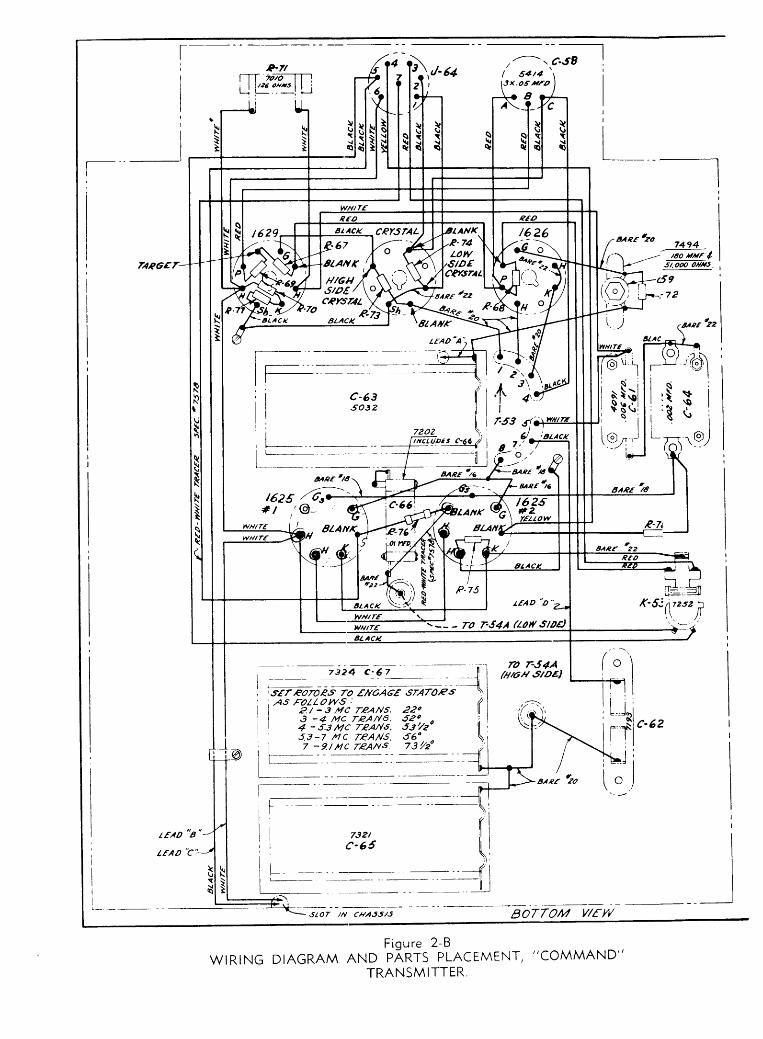
F igure 2 -BWtRtNG DTAGRAM AND pÀnrS PLACEMENT, "COMMAND"
TRANSM ITTER
c-63so32
-- - To r'54A Ao,r.îtadt
t fAD 'c ' :

70 H/6H,î/oéoF c-60
799/7 4 7 17248 |721e I72601
III
P0AR V/f W
7703
FEA_
wrRrNG DTAGRAM AND F,XITr';L.mENr,,,coMMAND,,TRANSMITTER.
( zt - a tîc rzAllsI3-+ tcTe/4ns.
< 4-.t3 mc 7e4/fs.I e g-7 /L/C rpArts.| 7 - 9./ mc TPAtrt
79?260336034603560J6
r z -52| 2/ -3 t lc reAf l î) 3 -4 îlc TpAlvS| 4-.f3r/C rP4rYSI e3-7 lVC 784^/s\7- 9./ rtc fP4ns

l0 Sunprus Reoro CoNvpnsrow
/?sK7RF A/'/P
/2K8/'//xER
snrEol z- 5cEF O'CILLATOE
SrnrEOL Z-5DPF,'/U'PLIF|EF
sYt4 BOL Z-54PF ANTEilNA
/25K7F/P5T
/F A/u/P
/ ? s K 75€CO/{O/F AlqP
/2527otT- crl 05c
/ - _ _ c A u lJ-3 C0/f rEdL
/s y/€rrED L/tlé
fP,1t ourstDE
/ 2 A 6AAo/o AtvP
eeoalfo...'.-
e - 2?
ctl o,tcsrur-oFf
I /'Yt
îrftîEol z-l/ s r . lF(2530 rc)
SYMaoL Z-22tro. lF(2830 Kc)
îYM8oL z-3e2o.lF(2830 Kc)
Sflrf 8OL Z-4ctf osct:LAToz
(28Jo Kc)
5rîr80L r-/ourPuT rP/lltSFOCúEP
-:"t.,/-lAS VIEWED
ct dtc.tHar-oFr l/nt
FPojq ourstDE
At v/twaDF20/" OaTS'/Dt
clccu/rs n PF cotL sEC /F CaUPL/N6 t/t//75,ct4 O€ClLLAfiOP,AND OUrPUT. reAÌlsFaeftrEP.
rHe |€Q/j///lAl /V,ÈrBEes oN THESE ANtrS AGPEE ty/TH T/t0sE CHowN Ar ruE CoeeESPaNDlNG
lacAno/v€ olv rH; w/E//v6 DlA6PAM.
PF CO/L s�ETsrlfaoL z-5 /F couPLtilo UN|TS
ffil \aell
ffil'<::/l
@lY-:/ |
Figure 3-ASCHEMATIC, "COMMAND" RECEIVER(ATA-TYPE PLUGS).

Maxuer-. Voluur III I I
CAPA C/TA.ICE5 /NOUCTANCfS PfSBTANC.S
c-/ I 5 ilHFc.2 /5 H4fc -3 /oo iilFc - qA n G),6A/tt (6 2,yH F.)c-t I sHFoc - 6 (A,4d
) . oJ/ oq ot tvfoc- 7 (4. q d I os/ o,/.ailtFoc-8 ) 2aOEMFc-9 | 40 rtrtFc-/o I 24OH/4Fc-// 1 3 ̂ /rrFc-/2 | reonurc-/3 | /7 HHFc-/4 | /eolrrrFctt(a, 8,c4 .ot/ot/ os xFoc16ap,c) l . 2 2/2 2/. 22 Hmc-n I tîo nnFc -tE
I t7 HnFc-19 | /80ìtHFc-zo qe,cl | . ot/ o 4 oi tFoc-zt I t7 nÈrFc-zz I rco amrc.23 | /oo*rHFc-24 | 2oohìtFC-?5 | .oo/ MFD Ic-?6 | /oo4br Ic-27 I /8o MHF Ic-za | 34HHF Ic - 2 e l . o o ó H F o Ic-to | ltHFo Ic - t t | .oo l4 ro Ic-32 I tFto IC-r' I wEtfrc cAP- l)
I actrancr(utsll
I .HAN eHMF)l
t It l tt l l
L-2, L.1L-4,L-tL- 6, L-7L.81 L-9L-/O,bL
lr2,t- tt
/../6
RF OSC
c t o d cRt cHoK4//2 rf/ceo-
3 HEUEIES
2-/P-2a-32-1t-52-6
2-8e-9210
P-t22- ttc-t12-t62-t6P - t 72-t0
P.2A2-?lE - 2 22- ?t
| 620
| 2,0@,000| 5/,OOO
I ezo| /540Oo
I no,oooI 2Òo
| ,oo
I ezo36q@O/0o,ooo5tozoolo0,ooo1t005l,0oottl ooo'tq0oo/o0,ooo2,ooqN/too ]Tooo I7000 |
68. SCz€€/t Celo6s./et). ScptEt G2lq HEX,OE SEcr/Ott6.@tc). coflr2oz éPta osc sEcnîî|P ' PtArEP(/e&. PttrE, //ExooE ,9Ec7tot1Pobad, Pl'aT€, OsC. SECT/oN6 aex2 , 64n7241 6e/D, HEXùDE 'tc|lùtt
Figure 3-A (cont inued)
rrnd the ner,v calibration rn:rrks placed on the surface\vith India ink.
A suitable "control panel" for the front of the re-
ceivcr is shown in figure 6. Rernove the auxiliary plugat the bottom of the front panel, knock off thé fnoÈand use the panel as a rnount for the components.
Moke o Novice Receiver for40 ond 80 Meters from
the 3-ó Mc. Commond Receiver!The 3-6 lvlc. Command receiver "iust
misses,, the7 NIc. Novice amatelrr band. An excellent and easy-to-perform conversion of tliis r.eceiver rvill permit lt tocover both Novice bandsl Simply rernove tfre coil rackfrom the receiver, and remove the coils from the cars.Mark the coils so you can distinguish between them,With _a pair of 'heedle-nose"
plierí pull out the micartaclip that secures the porvdered iron sluqs within thecoils. Remove the three slugs and discùd them. Becareful not to damage the coil windings or the termi-nal connections, Reassemble the coils, solder all con-nections, and install the coil rack in the receiver.
Using a sigrral generator, set the 6 Mc. dial mark_ing to a generator frequency of 2.4 Mc. by adjustingthe high frequency oscillator padder 1C-iC;.' Next]set the 3 NIc. dial rnarking to a generator frequencyof 3.4 \'Ic. Go back to 7.4 -\Ic. anà recheck this-poiní,Re-set C4-G_slightll', if necessan,. peak up the
-mixer
trimmer, and the antenna trirnmer, The rèceiver will
3or1 $ne the range of 3.4 \'Ic. to 7.4 Mc., coveringboth the 80 meter and the 40 meter Novice bands.
A Plug-in Power Supply for yourCommond Receiver
Many amateurs and experimenters have a whole"stable" of Command receivers. Not only is it ex-
pensive to purchase power transformers for each re_ceiver but it is verv difficult to adapt a receiver con_verted in such a rnAnner for mobiÈ operation. De-scribed herervith is a plug-in power unlit that fits inthe dynarnotor space of the reòeiver. The supply canbe easily removed and a converted dvnamoì6r'usedfor mobile operation.
First, wire all filaments in par.allel for 12 volt oper_ation. Locate a Commald receiver dynamotor (DV_g,or DY-2A/ARR-2) and remove the base mountinsplate. Discard the dynamotor. Remove everythin[from the base plate, including the sliding clips, buiretain the three pin connector. Nlount the-new powertransformer, rectifier tube, socket, and filter capìcitoras shown in figure 7A. Note that the capacitòr andlectifier tube socket are mounted on %,, métal spacers.The transformer is rnounted on X,, metal spacers sothat the leads rvill not be pinched between^ the coreand the plate. It is only necessary to drill holes in thebase plate for the four metal spacers nnd the 6-32screws that secure the porver transformer. The linecord is held in pltrce rvith a cable clamp secured underone of the transformer monnting bolts. A srvitch mavbe placed in tlre l ine cord.
roét setE r r€,?il/lALSà5 r'/Ít€o fRoH èorro|t
/îi\/7 aì \( " / \ ' n \\6.c" \--l
s" .7\ r G - . /\:*r9./
7U8E rtEMtNAt COOÉ5 . S | E L LH. lEATEP
K = CATHODE
Sq=SUPPQESSOF G2/OOpt-F/PST O/1OE PLAÍE
oP2! SECO|O O/ODE PIArE
6=coNrzoL 6R/o
Mc. on the tuning dial. Retune the signal generatorto 54 Mc. This should iìppear at 6 N{c. on the re-ceiver dial. Peak up the mixer trimmer (on the sideof the tuning capacitor ) and the antenna trimmer onthe front panel for maximum signal. Calibration mavbe varied by juggling the oscillalor padding capacitoiC-9 and the :ruxiliary oscillator capacitor C-4 on theside of the tuning capacitor. When the coverage iscorrect, the dial may be re-painted with white paint

Nsèùa
taì
d.LU
LUL)l.tJu.
oz
o =a à =- og nf ì(')
L L =
É.(9
ouzd.
;
IIiIII
|qìì lS !9 \
I
se lù N
i !ò-5t
,\$!i
t-:\ì
Ìú-Ù
a
(J
f
,/'l^ i r ìú \ t , t
\ r ì
:-g4i ! tÈ, \ o 5 $ . r
lsi-r ['i>
î$èS.;
s-{to."J\4;-ì'\lt -- o.\
T\--'* -Î7N \ : f f
Wtrs
-\
ì ì ) ?b i r ' U. d r . /
___l

Sunpr-us Reoro CoNvnnsroN MeNuer, Voluur III l3
Mp/N6 ABOV( 7A6f aECK
íffP taro ?aP.tlat Df26E U Afl6 COUOaUSQolEE rcZ*m
Eno y/*of6t/6 AflXlSeC
F igu re 3 -B ( con t i nued )
A/O7f5.I At. fr/3f5 k2(ao y/rH cOlO? rcar ret '22 gzto
co?pa4, */4? s?fc/a/ctT/u rtr r" a*aa", n *-rao.Z-. A,a2a U/2A tE 7/dflCO Ca2pap t/aH S/ZÍt lS tutdJ. sf,At Att sunero coNnccrrca, wn nîo àcoill4 .EPH/dAL ,yuhaeps .ruouil Aèe r,p /Détr/./CAr/OflpucposEs. rltr oonorApp€Ap on rHé ròiiimenr
ExcE T on ruaE socrEr.t ato oureuT ipa-titìapi7í'
e,/
The schematic of the supply is shown in figure 78,rrnd a photo of a tvpical supply, installed in a receiveris shown in figure 8.
A Twelve Volt Commond Dynomotorfor Mobile Service
It is often desirabìe to emplov a Comrnand receiverfor mobile or Field dav operation. When using the.r.c. power pack described in the previous section, thereceiver may be easilv po*'ered with a l2-volt dyna-motor, Although l2-volt dymamotors for Commandreceivers have occasionallr' ;rppeared on the surplusmarket, they are not generalh'available. The DM-34D(part of the BC-603 equipment ) is quite common,holever, and is the same phvsical size as a Commandset dynamotor, delivering 220 volts at 80 ma., with:r primarv druin of 12-11 volts at 9.8 irmperes. It maybe used rvith the Command receiver rvith a simpleconversion.
Obtnín a 28-volt Comrnand receiver dynamotor.Remove the mounting base, complete with slidinglatches, socket, and ground lug. Discard the dynan.o-tor. Nov', cut the DM-34 mounting brackets to
2-9/16" so that the brackets will just fit inside the up_turned fìanges of the Command dynamotor base. Drillrr small hole in each DN{-84 bracket and a correspond_ing hole in the base so that the dynamotor miy be
s r a N c o R p c - a 4 o t 6 X 4 O R I G I N A L C H O K E# 5 6 3 4
l + + l
| 20 !F I:*im-v.*
1 ' . 6 V . T O A L L O Î H E RF I L A M E N T S
6 . 3 V . T O W E - 7 1 7 AF f L A M E N T
)l - ' È - - - + r o c A i N c o N r R o L L | N E25!! l 9-4!! (e nttp , , r , t
Figure 4A.C. POWER SUPPLY FOR COMMAND RE-CEIVER. Power tronsformer del ivers 235-O-23_5 volts ot_40 mo., 5 vol ts ot 2 omperes, ondó.3 vol ts ot 2 omperes. l f ó.3 vol t winding hostwo center-top wires, cut them short ond
solder them together, then tope.

14 Sunpr,us Renro CoNvBnsroN
,er ls6c
B
- E L E C T R O L Y T r C\ M O U N I I N G G R O U N D L U G
ì P L A Î E Í O P S I D E
o s c r L L A î o R c o r L
PFl- 3 a +22 PLAST tC-C O V E R E D
s É c . - a T . + 1 6 È N A M .
@
@ + A
. 1 "+ 2
S T A N C O RP c - a 4 o t 6 X 4
A - O R I G i N A L H O L E - D R I L L O U Tf a 1 / 6 "
B - N O T U S E D I N C O N V E R S I O Nc - A o o H o L E . r / 4 4
s r a N c o P P c - 8 4 0 1P O W E R T R A N S F O R M g R
N O T E S I 4 I É C O / L S C L O S E W O U N D , I / 4 " D l A M E T E R
v / E w s L o o K / N 6 D O W N O N C O / L S
P R / M A R / E S W O U N D O V E R S E C O N D A R / E S
Figure 5COIL DATA FOR SIX METER CONVERSION
OF "COMMAND" RECEIVER.
F igure óCONTROL PANEL CONNEC.TIONS FOR "COMMAND"
RECEIVER.
A-Loyout,
/:\fó,
F i g u r e 7power supp l y moun t i ng p lo te f o rCommond rece i ve r .
B-Schemot ic , power supply. Power t rons-fo rmer i s t he some os shown i n f i ou re 4 .
t A )
T : T O P O F C O I LB : g O T T O M
A N Î E N N A C O I L M I X E R C O I L
7 T + 1 6 E N A M . P R / . - 1 0 î . + 2 2 P L A S T T C -C O V E R E D
s 6 c . - 8 a * 1 6 E N A M .
P H A S E C O R P E C T L YFOR | / .6 V . , THENS O L D E R A N O f A P E .
bolted to the base. Connect the rohite uire haoing ablack tracer and also the ushite roire haaing a red tracerto the ground lug. Connect the whíte uire to thefilament lug on the dynamotor base ( see figure 7Afor base connections). Finally, connect the uhite wireaith the blue tracer to the B-plus lug of the base.
The above connections are for automobiles havingthe positive terminal of the battery grounded. If yourcar has the negative terminal grounded, reverse thewhi,te wire with the uhite wíre harsíng a black tracer.A reworked dynamotor is shown in figure 8.
Converting o Q-S'erfor Broodcost Reception
The Q-5'er ( BC-453 ) covers 190-550 kc. and isgenernlll' used irs a selective i.f. strip for communica-tion receivers. B1,' modifving the coils it may be madeto cover the broadcast band (550-1500 kc. ) for gen-elal broadcast reception. It also can be used with aconverter for mobile u'ork, or it can serve as a Q-5'erfor receivers such iu the BC-3-18 s'hicli havt' ir 715 kc.intennediate frequencv channel.
Figure 8,,COMMAND" RECEIV-ER POWER SUPPLIES. A tlef t is converted DM-34dynomotor, ond ot r ightis the power supply of
f igure 7 .

-\ l lxuel, \roluur III t5
The coil rack is removed and the follorving altera-tions iue ruade to the coils:
l-Remove 210 tr-rrns fror.n the iuttenna coil lL_l).')-Rernove 500 turns from the mixer coil Drimarv( L - 2 ) ,
3-Rernove '220 turns from the tnixer coil secondarv( er id )
{-Remove 195 turns front the oscill:rtor coil sec_ondirn' ( L-5 ).
Do not remove itnv turns from oscil lntor coil pri_nrarr' (the grid t ' inding). \\ 'hen con.rpleted. ."pù""the coil lack. The receiver u'ill norrj tune the fre_(prencv ranse of 550 kc.-1600 kc. -{.djust liigh fre_
A U D / O
I 2 A 6
F i g u r e 9S C H E M A T I C , N O I S E L I M I T E RFOR COMMAND RECEIVER.
91el9y alignment rvith tlie oscillator shunt padders(C 1E, 9-+C) on the variable tuning capacitor. Trackthe low frequency end of the band ùitfrin" adjustablepowdered iron slug-cores in the three coils, pt", tfr"oscillator series padder (C-g) on the end of thà tuninecapacitor.A Noise Limiter for your Commond Set
Tired of automobile eRM or static on your Com_rurrnd set? A very simplà but effective noise limitercan be connected as shown in figures g and 10. A124L5 tube is used. The cathodJ of one_half of thediode is connected to the 1246 control grid. The grìàof the 1146 is slightll, negative, so the àiode does"notconduct; however, rvhen a noise peak arrives (or astrong audio peak) the diode conducts and shortì theglid, circuit out to ground. The limiting action is asgooct as the more complicated shunt_type limiter, butthe audio distortion is a little l-righer.' A s*itch'maybe incorporated to remove the liniiter from the circuíts4ren it is not required.
Automotic Volume Control forYour Commond Set
Autornatic volume control is extremely effective inpreventing distortion or overloading on strong localsigrrrr ìs. I t is ver.r ' s i rnple to add i ì . \ . .c. to the CoÀmandleceivels. ( \ote: A fe* ' 'ARC" ser ics receivers haveir.r,'.c. incorporirted ). All tl ie essential a.v.c. com_ponents rrre incorporrrted in all receivers, but there is
) t za ts
F i g u r e I 0The ì2AL5 no i se
l im i te r t ube moy bep loced i n t he unde r -choss i s o reo beh indthe pcnel of the re-
ce ive r .

Sunpr-us Ranro CoNvpnsroNt6
v î - i 3 11 2 S K 7
v f - 1 3 3 V T - l 3 l1 2 S Q 7 1 2 5 X 7 I--l:r"-: \ a - 9 | M C . )
u€ w-M / X E RS T A G E
3 0 0 K c . l - FS i G N A L
z-3
+@
O R I G I N A L
@M O D I F I E D
F i g u r e l lS C H E M A T I C , A . V . C C I R C U I T F O R
, ,COMMAND" RECEIVER.
no connection betu'een them. The purpose of this
conversion is to provicle ir.r'.c. action to the r'f' and i'f'
amplifier stages bv completing the a.v'c' circuit' It
r."qìir", tu,o.iidditional reìistors and a ca,pacitor' Refer
to i isures 11A and l1B. First, unground pin 5 of tìe
l2SÒ7 (\ 'T-133). Connect t l ie 100 ppfd. capacitor'
,."roì, pìns 4 and 5 of the tube socket' Connect the
470K ràsistor from pin 5 to an adjacent ground lug'
Connect the seconcl 470K resistor betu'een pin 5 and
the junction of C-l5A and R-11. Remove R-11 from
the i'irc'uit to increirse the effect of the a.v'c. action'
A Built-in SPeoker for YourCommond Receiver
A srnirll speaker may be mounted in the removable
aclapter platé in the front of the Command receiver'
The "tueaker" is the smirll receiver element in standard
trse in ìelephone l'randsets' It is only Lk" in diameter,
and 11116; tliick. It is :ivailable on the surplus mar-
ket, and identifiable bv the letters HA-l stamped on
the face.A blank trluminutn plate replaces the original
rdapter plate. A hole is cut in the plate -just large
enoi sh tà clear the HA-l unit. A second hole is made
for the gain control, shos'n in figure 6,If th; b.f,o. su'itch is not used, placement of parts
on the new plate is not critical. However, if a b'f'o'
switch is desired it rvill be a tight squeeze to get the
three components together on the new adapter plate'
A single layer of "Scotch" electrical tape is w-rap-
ped around the shell of the speaker to isolate it from
F i g u r e ì 3BLOCK DIAGRAM OF DOUBLE _ CONVER-SION AMATEUR BAND RECEIVER MADEFROM TWO "COMMAND" RECEIVERS. BC-455 serves os r . f . port ion, ond BC-453 serves
o s " i . f . s t r i o . "
F i g u r e l 2SCHEMATIC, HA- I SPEAKERFOR USE IN "COMMAND"
R E C E I V E R .
the chassis, trnd after placing the speaker in the hole
in the plate a second piece of terpe is r'vrapped around
the body of the speaker to hold the unit from slipping
out of the hole.\\/ire the positive side of the speaker directly to pin
#4 of J-I (the front plug in the back of the adapterplate). \Iount the gain control ' \\ ' ire the
"hot" arm of
ihe control to pin #Z of 1-t, and the other side of the
control to pin #1 of J-1. Fintrlly, counect the other
side of the ipeaker to ground. Scres'the adapter plate
to the front of the receiver, and you have a sensitive,
clean-sounding speaker, audible manv feet from the
leceiver. ThJcomplete wiring changes are shown in
figure 12.A "Double Conversion" Commond
Receiver for Single Sidebond ReceptionIt is possible to combine two Command receivers
to form à double conversion receiver, rvell suited for
single sideband reception or selective c,w. reception'
Th; BC-453 (190-550 kc.) and BC-455 (6-9.r Mc.)
receivers are used' A block diagram of the combina-
tion is shown in figure 13. The BC-455 tunes the 7 Mc'
amateur band (oiit may be modified for other bands
as described later ) and the intermediate frequency
signal of this receiver ( 2830 kc. ) is c_onverted to 300
kA, within the tuning range of the BC453. The com-
bination provides exòeleni sensitivitr', selectivity, and
freedom from bothersome "image" signals.
Only a portion of the BC-455 is used. The r"f ' am-
plifier, mixèr, and first i.f. stirge function in the usual
i.u.."., irnd are unn-rodified. The second i.f. stage( 12SK7 ) \r-5 is changed into tr mixer, and the b'f'o'
section of the l2SR7 (V-7 ) is converted to a mixing
oscillator. The 12A6 ar-rdio tube is removed'
H A - I S P E A K E R U N I f
V.rs 'c"* \
N E W 0 5 C . S r A G € - T U N E r A 2 5 3 4 k C .
éî,i 'LîJ'8f, olfi o", n,,

\fexu,c.r, Vor,uun III T7
The, first step is to lower the frequency of thel2SR7 beat oscillator until it operates 300 kilocyclesbelow the intermediate frequency of 2830 kc. The newfrequency of oscillation is therefore 2b30 kc, To effectthis change, solder a 100 ppfd. mica capacitor be-trveen the plate (pin #5) and ground (pin #f ) of thel2SR7 socket. The desired frequency of 2830 kc. maynorv_be tuned by adjusting the b.f.o. trimming capaci-tor C-28 on the side of the receiver. Check the fre-(luency by listening to it on a nearby receiver or fre-quency meter. The old b.f.o. has now been trans-formed into a suitable mixins oscillator.
The next step is to couple the new i.f. output fre-(Iuency of 300 kc. (2830 kc. minus 2530 kc. ) into theBC-453 which serves as the lorv frequency i.f. ampli-fier, Remove the third i.f, transformei from iheBC-455 (trirnsformer Z-3). Solder a 30K. l-watt re-sistor between pin #1 and pin #2 of the i.f. socket.Solder a I00 ppfd. cirp:rcitor betu'een pin #1 .rndpin #4, rvhich is used as a tie-point terminal. Finally,cut a short length of shielded rvire, long enough ioleach from pin #4 to the antenna terÀinal oT th"BC-453. Solder the center conductor to pin #4 of i.î.transformer socket Z-3 and solder the shield to a near-by ground lug (pin #5 of 12SR7 socket), Connectthe inner conductor to the antenna terminal of theBC-453, and ground the shield to the chassis of thesecond receiver.
Tune the BC-453 to 300 kc., and tune the BC-45Sto 7 Mc. You can now tune in 4O-meter signals bytuning either receiver. In general, tune the BC-455 tothe edge of the amateur band, and then cover theband on the BC-453. The i.f. bandwidth of the hishfrequency receiver is broad enough to allow yo.,
.-to
tune the BC-453 for 100 kilocycles or so without adrop in received signal strength. Use the b.f.o. in theBC-453 for s.s.b. or c.w. reception.
- As 1n example, suppose you want to tune in a sig-nal at 7150 kc. Set the BC-453 to 300 kc. and then tunethe BC-455 to 7100 kc. Next, tune up 50 kc. on theBC-453, and you are "on
the nose" at 71b0 kc. In thisway, you can read your frequency of reception to oneor two kilocycles. Alrvays remember to set the BC-459tuning dial to 300 kc. for general tuning rvith the BC-455.
Converting the BC-455 for20, 15, ond l0 Meters
Conversion for Citizens Rodio ServiceIt is possible to buy extra r,f. coil racks on the sur-
plus market for the Command sets. To change bands,it is onlv necessary to rewind these racks, and thento use them as plug-in coils in your BC-415.
To rework a rirck, the data of figure 14 mav berrsed. You will need to borrow anothei receiver oi ft"-quency meter in order to listen to the mixer oscillatorof the BC-455 during the tracking process. Removethe coils and rewind them to the specifications givenin figure 14, You can check the approximate resonant
frequencies by placing the coils in the receiver (with-out the-shields) and noting the resonant frequency ona grid-dip oscillator. Be sure to remove the iron corefrom the mixer and oscillator coils. When vou havemodified the coils, solder all connections, place themin the rack, and replace the rack in the receiver. Turnon the Command set, and then look for the sisnal of!h9 hig[ frequency oscillator in a nearbv receiver.Adjust the trimming capacitors on the or"illoto, ,""_tion of the tuning capacitor (C-48, C-4G, and C_g)until the oscil lator tuning covers the desired tange.Finally, trimmers C-2, C-4D, and C-4F are adiust*eclfor maximum strength of received signals. Tlte laststep is to cover the tuning dial with rrhit" enamel andlecalibrate the bigh frequency bands with India inkdirectly on the dial face. Only one or two markingsaue required for each band, as the main tunins is doiervith the BC-453 dial. The 28 N4c. coil data,"also ap_plies to the 27 N{c. Citizens Radio Service."Hop-Up" Your Commond Receiver for
jmprov.ed High Frequency Receptionrt ts possible to boost the gain of the Command set
and to materiallv improve recèption on the 10, 15, and20 meter riìnges. To do this, the l2SK7 i.f. amnlif iertubes irre replaced u'ith l2SG7 tubes, and tlre i:SfZr.f. i implif ier trrbe is re;tl irced u.ith a 12SG7. It is ri lsonecessary to los'cr the cathode bias resistor R_l on ther.f. tube. Shunt R-l rvith a 620 ohm, X-rvatt resistor.In^-addition, bypass socket pin #5 to ground with a0.01 pfd. disc ceramic cnpacitor. To Èoost tl,re gitinof the i.f. amplifier, shunt:the screen resistor (R_22)rvith a l0K, l0 watt resistor.
Figure ì 4COIL DATA FOR CONVERTING BC-455 TO
1 4 , 2 1 , O R 2 8 M c .
B A N D
A N T E N N A C O I L( L r )
M I X E R C O I L( L 5 )
O S C I L L A T O R C O I L( L i 3 )
! . O F T U R N S L E N G T H N ' O F Î U R N S LENGfH N O O F I U R N S L E N G T H
1 4 M C . 3 / A t 3 / E ' 7 t / z
2 l M C 5 1 n 3 6
27 MC28 MC 1 / O ' 5 l / 6 , z 1 / 2 1 / 4 4
W I N D A L L C O l L S W l T H N O I A € N A M . V / R E .
NOTE.: REMoVE w/NolNc Lz FRoM ALL HIxER coILs. (PLATE ulNoINco F t 2 S X 7 R - F S . A C E ) .P L A C E I O O ! ! F C A P A C I T O R A E T Y € E N P I N * T A N D P I N # 1 O Fu/xER co/L socKET Z_5A.l ! .4c! 6ry, t -warr REstsroR oErwEEN prN{1 aND plN * z oFTHE SAME SOCKET
( s E E F t G U n e 3 a )

18 Sunpr.us Ralro CoNvBnsroN
If the gain of the receiver is too high, instabilitymay result. It can be eliminated by experimentingwith the value of these two shunting resistors. Try1000 ohms across R-l and 15K across R-22 iÎ the re-ceiver shows signs of feedback or oscillation. See fig-ure 3 for receiver schematic and parts placement.
Conversion of the BC-603 to ql0-t t -15 MeterAM/FM Receiver
( ldeol for the Cit izen's Bqnd!)The BC-603 f.m. receiver is a component part of
Radio Sets SCR-508, 528, and 538. It provides f.m.reception over the range of 20-27 Mc., has a sensi-tivity of one microvolt, and 80 kc. bandwidth. An in-
termediate frequency of 2.65 Mc. is employed, anda self-contained audio amplifier provides 2 watts ofpower for a speaker, or 0.2 watts for headsets. On 12volts the battery drain is 4 amperes. Properly con-verted, this inexpensive surplus item makes a goodhigh frequency a.m./f.m. receiver. The original BC-603schematic is shown in figure 16.
Adding An A.C. Operoted Power SupplyThe purchaser of the BC-603 should try to obtain
both the l2-volt dynamotor (DM-34) and the 24-voltdynamotor (DlI-36). The 2S-volt unit is of littlevalue, but the base makes an excellent foundation forthe a.c. power supply. Remove all components from
Figure l5BC-ó03 F.M. RECEIVER MAKES HANDY l0- l I - ìs METER A.M./F.M. RE-CEIVER. A.c. power supply is shown mounted in dynomotor well of receiver.
\'IeNuer, Vor-uun III 19
this brrse and discard them all, except the lg-pin' 'Jones" c,orrne<,tclr. Clerrn all l trgs on ihi, "onr,""io,
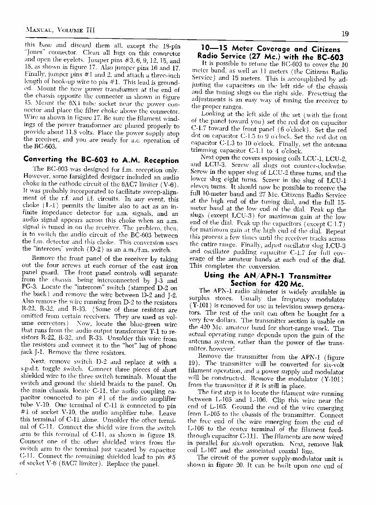
and open t l ie ey 'e lets , Jumper p in i #3, 6,g,12,15, and18, as sl.rorvrr in figure 17. Also jumper pins 16 zurd 17.Finalll', jumper pins #1 and 2, and attaòh a three-inchlength of hook-up rvire to pin #1. This lead is ground-c:d. \Iount the nerv power transformer at thJend ofthe chtrssis opposite the connector rrs shorvn in fisure15. \ft lrnt the 6X.1 tube socket ncar the porr,"r. "on_nector and place the filter choke above the connector.\Vire as shotvn in figure 17. Be sure the filament rvind_ings o{ th_e power h-ansfonner are pliased properly toprovide abont 1I.8 volts. Plirce the pos.er *ppty utopthe te_ceiver, and vou are readv foi rr.c. opàratlon o?the BC-603.
Converting the BC-ó03 to A.M. ReceptionThe BC-603 rvas designed for f.m. reception onlv.
Horvever, some farsighted designer includeà an audíoclioke in the cathode circuit of t le 6ACT limiter (V-6).It rvas probablf incorporated to facilitate srveep-align_ment of the r.f. and i.f. circuits. In any "rr"ìt. thi,cl ioke (L-1 ) permits the l imiter also to act as an in-finite impedance detector for a.m. signals, and anaudio signal appears trcross this choke il,hen an a.m.signal is tuned in orr the receiver. The ltroblem, then.is to su-itch the audio circuit of the BC-603 betweenthe f.nr. detector i ind this choke. Tli is conversion usesthe "intercom"
srvitch (D-2) as an a.m,,/f.m. switch.Remove the front panel of the receiver by taking
out the four screu's at each corner of the cast ironpanel guard. The front panel controls will separatefrom thc chassis, being inter.connected b1' J-3 andPG-S, Locate the "intercom"
srvitch (stampedD-2 onthe back ) ancl remove the rvire betrveen fj-2 and I-2.Also remove the u'ire running from D-2 to the resisiorsR-22, R-32, and R-33. (Some of these resistors areomitted fror.n certirin receivers. They are used as vol-ume correctors ). \ou', locate the blue-green wirethat runs from tlie rrudio output transformei T-l to re-sistors R-22, R-32, and R-33. Unsolder this wire fromthe resistors irnd connect it to the "hot"
lug of phonejack J-1. Remove the tlrree resistors.
Next, remove srvitch D-2 and replace it rvith as.p.d.t. toggle srvitch. Connect three pieces of shortshielded u'ire to the tlirec ss'itch terminals. N,Iount theswitch and ground the sliield braids to the panel. Onthe main chassis, locate C-ll, t l ie audio coùphng ca-pncitor connected to pin #t of the audio amplifiertube V-10. One terminal of C-11 is connected [o pin#1 of socket V-10, the audio amplif ier tube. Leàvethis terminil l of C-11 irlone, Unsolàer the other termi-nirl of C-l1. Connect the shield u'ire from the sn,itchirrm to this terrninarl of C-11, its sìron,r.r in f isure lg.Connect one of the otl ier shielded u,ires fiom theswitch arm to the terminal just vacated bv ctrpacitorC- l l . Connec. t the r .emir in ing s l r ie lded lead to i - , in +;of soc,ket \ ' -6 (6AC7 l imi ter) , Replace the p i rnei .
l0-15 Meter Coveroge ond Cit izensRodio Service (27 Mc.) wtth the BC-ó03
it is possible to retune the BC-603 to cover the 10n.reter band, as well as 11 meters (the Citizens RadioService) and 15 meters. This is accomnlished bv ad_justing the capacitors on the lt,ft sjcle ìf tn" cliassisand the tuning slugs on the right sicle. presetting theadjustments is an ensv rva1, of tuning the receivér tothe proper ranges.
^ I.ooking at the left side of the set (rvith the frontof the pnnel torvirrd vou ) set tlie red dot on capacitorC-I.7 torvard the front panel (6 o'clock). Set fhe reddot orr crrptrcitor C-l.5 tir g o'cìock. Set ihe recl clot oncapacitor C-l.3 to 10 o'clock. Fintrl ly, set the antennatrimming <.apacitor C-l. l to 4 o'cloók.
_N_e1t open the covers exposing coils LCU-I ,LCTJ_2,and LCU-3. Screrv all slugs oirt counter-clockrvise.Screrv in the upper slug of t-bU-f three turns, and thelorver slug eight turns. Screrv in the sl.rg oi LCU_Ieleven turns. It should norv be possible to-receive thefull l0-meter band and 27 Nfc. Òitizens Radio Serviceat the high end of the tuning dial, and the fuil lS_meter band at the lorv end of the dial. peak up theslugs (except LCU-3) for maximum [ain at thé lowend of the dial, Pcak up the <.apircitors (ercept C-1.7)for maximur.rl gain at the Iiieh énd of the dial. Repeaith is process u f t 'u ' t i r r r t 's r rnt i l t l re rccei r .er t racks ac^rossthe entire- range. Finrillr', irdjust oscillrrtor slug LCU-3rrnd oscillrr.tor prrdding cir.pacitor C-l.7 for Iull cov_erage of the amerteur bands at each end of the dial.This completes the conversion.
Using the AN/APN-I TronsmirterSection for 42O Mc.
The APN-I rndio altimeter is r.videly available insurplus stores. Usually the frequenóy modulator(Y-101 ) is removed for use in televiiion sweep genera-tors. The rest of tl.re unit can often be boughi for avery ferv dollars. The trtrnsmitter section is ùsable onthe 420 \Ic. amtrteur birnd for short-ranse work. Theactunl operating range depends upon the gain of theantenna s)'stem, rather than the power of the trans-mitter, ]ros'ever!
Remove the transmitter from the ApN-l (figure19). The transmitter rvill be converted for iix-'voltfilament operirtion, and u porver supply and modulatorrvil l be constructcd. Remove the modulator ly-101 )from the transmitter if it is still in place.
The first step is to locate the fila^ment rvire runninsbetrveen L-105 and L-106. Clip this rvire near théend of L-105. Ground the end of the rvire emergingfrorn L-105 to the chassis of the transmitter. Connec*tthe free end of the u'ire emerging from the end ofL-106 to the center terminal of the filament feed-through capacitor C-111. The filaments are nor,v wiredin parallel for six-volt operation. Next, remove linkcoil L-107 and the irssociated coaxial line.
The circuit of the power supply-modulator unit issliown in figure 20. It cirn be built npon one end of

20 Sunpr,us Reuo Coxvnnsrox
MOOULAÎORv2
L C U S
L C U I F L 2
f-- I R F A M P
v l
- l
Irrr ('
J )
rs * ;
I F A M P
v 4
I
I F A M P
v 5
caPAcrr0nscr . r t6uuF NIAX.c 1.3 16 UUF ffar.C l.ó 16 UUF frlAxc 1.7 t6 UUF MAIc t.a 62 uur ilaxc r .4 62 UUF l l lx .c r.6 6t uuf lfar.c r8 6l UUF taax.c t 0.006 uF fOOvc I 0.006 uF !@vc + 0006 uF300vc 5 0 0 0 6 u F ! @ vc 6 0.006 t,F !@ vct 0006 uF :toovc8 500uuF 500vc9 0.006 uF 500Yc to o.75 uuF 600Vc r I 0.006 uF 300 v
ct2 0.o l uF aoovc 13 500uuF 500vc t4 0@6 UF IOOYc 16 0.5 uF 600 vc t 6 ? u F 6 ( ) 0 Vc 17 o.ot uF 300Yc 18 0.ol uf loovc 19 C.OOa UF 5oovc 20.r 0 | uF 600vc 2 0 2 0 l u F 6 0 0 vc 20. ! o . l uF 600 vczt 0.o l uF foovc2? 0005 uF 300YQ ? t 4 O U F 2 5 vc , 2 4 t u F 6 O O Vc 2 5 2 U F C @ Yc26 0.ooo5 W 5@v
o!5 0.006 uF rOO V
c 36 l0 uuF 500vc 3 8 l 0 u u F 5 0 O vc 39 0.006 uF IOOVc 4t ?00uuf 500vc4? 200 uuF 5@V
c4J too uuF 5OOVc44 30 uur 500Y
c 4 3 t O O U U f 5 o o vc 46 ?O truF SOOVc 5t 0.006 uF Jowciz rouurÀeouuF Soovc53 souur f s€E i lorÉ ?
n?2 3qooo^ t/u vtR2:! 5,OOO j- r/2 fla ? + 5 0 ^ 1 2 tR 2 5 ? $ O O ^ t / ? wR?6 l ,aOOJl Wwe?l 2,300^ t /zwR2t 2,500^ l /2YlR29 l3 ,OO0^ 2 wn r o 5 ^ 4 wRf, l 6 .800^ lYtR 3e 50,ooo ̂ l/2 wR 13 !O,O0O ^ l/a WRl7 25O,OOO^ l/2v'R38 | .OOO^ l /a IR4r r0o,oor)^ v2f iF + t ! q o @ ^ l v 'Ra3 Sqooo^ llR3r e5o,Ooo ̂ l/? lfR 5 a I O , O O O ^ V 2 V tR53 |OO,OOOTLI/8 l fR5+ l@tooo^vzl fF6t too,ooo^l /e l |n6a o l ,000r \ l / l f ln6l t0,0oo-r"_ t/a wn 6 4 l . o o o ^ l / ? wR?t a50,o0|orl l/2f,
n?e lo,0o0 ^ t/? tfRtll rO.0O0^ l/2 lln?+ t.ooorl l/e lfR6r TOTOOO 'r l/2 Vtn82 230,ooo-r! vg I
FS3 TOTOOO rL l/l tn84 25O,OOO^ l/t vlRO5 tpoo^ l / t tRCI TOO,OOO ^ l/2lY
R92 4qooo^ l , /2 tn93 +o,ooo ̂ l,'? vl
Re.l 2,OOoPoOn 72wRe5 l5 ,OOOÀ /2wR96 3gOOOrI 12 W
fI OUfPUf ÍRAI ISFORIER
vacuuM TUIÉSv t v f - l l 2 { 6 A C 7 )u 2 V r - l l 2 ( 6 4 C 7 ì
v 3 v f - 9 4 ( 6 J 3 )
v 4 Y r - 2 0 9 ( 1 2 S G 7 )v 5 v f - 2 o g l t 2 s G 7 )v 6 v f ' l , e ( 5 A G 7 )
o ^ l -o r O i Dt J J J
v 7 v r - 9 0 ( 6 H 6 1v 0 v T . t 0 7 - A ( 6 v 6 6 1 )v 9 v r - 2 ? 9 ( 6 S L 7 6 f )v t 0 v f - a 2 t ( 6 S L 7 G T )
OY IIAMOTOR S0 M . 5 4 . O 1 2 v O L ÎcapAc | îoRsc t o r 0 0 0 3 u F t o o o vc 7 0 2 0 0 0 3 u F t o o o vc 703 0 003 uF 500 vc 7 0 4 0 . O O ! U F 5 0 O vc ? 0 3 0 . o o 3 u F r o o o vc706 0.oo5 uF tooo v
corLsL T O I H V F I L T E RL 7 O 2 L V F I L T E NL 7 O 3 X Y F I L T E RL ? 0 4 H V F I L T E R
J 7 0 r 0 Y n a l i o r o R , l A o f
x070} t?v 0Yrt^Lofoff
oL-36-O 24 YOLfc a 2 a c r l 0 P sc r o t 0 . o o 5 u F t O O 0 Vs 8 0 2 0 . 0 0 1 u F 1 0 0 0 vc 8 o 3 o . o o l u F 3 0 0 vc0o4 0.00! uF 500 vcEos 0.o0r uF looo Yc 6 0 6 0 . o o l u F t o 0 0 v
c,o rLs
L C O I F V F I L f E FLOO2 LV FILIERLOoS HV FTLTERL ! O 4 X V F I L T E R
tr80r oYt{axofoR Jaox
il6lor a4Y DYI{AMOIOR
J J o t a3ss s
t J ( f
Nn
S H
3PPARATUS LEGENO
cs4 souur-)^5,srlr6 569v l$* uMtrER cArHoo€ c|lor€c55 rouurf sEE ìofea Llz AxrErr{A couPLlt l6C56 0006 UF 3OOV LlS R F PLAT€c6t roouuF toov Lyl il(ro GRloc62 .OO|UF 300V Lal R F OSCILLAÎOnc63 SO UUr)-eOUur SOOV L 5l lsr lF GRloc64 rO uurl SEE xOrEA L5? TOÍXTLATOR pLAf€
c 6 3 , o u u r } e o u u r s o o v L 6 l 2 l l o l F G R l oc66 SOUUT]'- s€€ lroTE 2 UCa I ST lF PLIÍEc6? o.oo6uF 500v L7l L lL l fER GRIDc7t 50 UUF 5OOV L?? 2 t {0 lF PLI fEcf? .ooruF 500v L8t oETECTOR l t l9ufc?5 50uuFl.60uuF 500v 182 Llril l lER PLAÎEC74 rOuur" i SE€ NOTE 2 Lgt tFOSCILLAIORc 7 5 r o u u r j o e o u u r S o o vc?6 souuF"j" SEE xor€ 2 US, LO..,O SP€AXER
c7? 0006 uF 300vcot ?5OUUF 5OOV PoTElrTrOlr€fERSc82 ( t006 uF 300v Pl loo,ooo^
co! 0006 uF SOOV 72 2OO^c84 SUUF 500vcg5 50uuF oR 60uuF 5oovlrsÀltÍ PLUGS
C86 lOUUF OR 6OUUF5OOYJ'- - r ' - PGt RECEIVER PLUG
cE7 25l/uFìe rsuuF 5oov -
PGt DYl{atloTon PLUG
cs8 lo uuF -t'
sEE irolE 2 PGt FRot|T ÈNEL PLUG
c9t 50uuF 500vc92 50uuF 500v RESISTORSc93 TOOUUF 50OV nl l0rooo '/L lfl
c94 SOUUF SOOV n! z5qoooJal /z l rR3 500^ l/e wn4 3o,ooo ^ l/t w
surf cHEs R5 too ^ r/zvt
or REC O|r.OFf R6 IOO,O@JI l/zlv
02 RAOIO- Úrf R7 : lorooorL l l
05 cn-ofF sP€ar€R Rl ?qooo^ l /zw
04 OX-OfF solr€LcH n9 l,ooo^ t/zw
05 furE-oP€naÎE Rlo eSorooo^t /zwRrt l .oog@o^ l /av lRrZ 2,OOO^ tnVl
€t ctLL slGIlAL f,13 lqooo^ y2 IRl4 25O,OOO11 l/2 WRl5 I,OOO,OOO ^ r/2lr
Ft FUSE 15 AllP Fl6 lpoorooo^ l/zlfnl? eso.ooo^ l/8lfR l0 loo.ooo ^ l/a vl
JtcKs nt9 2,ooo,ooo-/t-l/?ìr
x PHollEs nzo loorL I Yf
J2 PXOtI€s i2 l 'o 'ooo^2$'
Jl tRotll P IIEL JACX
F i g u r e 1 6SCHEMATIC, BC-ó03 RECEIVER.
; - t

Mexuel, VoruuE III 2l
I 5 I A F A M PS r F o s cv to
-l lrurrsn
r v ó DerecToaV 7r n l ì | -
I J J J TÈD,E
vf v2 v6 v8
, I J r i o ó ó Ò ó ó ó ó ó ó ó ò ó ò ò ó ó :-J î Ir c _t_us T,r___g_ ,r_e E,r_ra re ,/u o " 5 e c r l g I g 9 I a 9 g a o o o o o o ; ; l
o O14 15t 3t2
O i
ileloI
iti ifuiíí;' giii'
U .
b - N
f
DYNAMoToR ov-ro-(*)t2 voLT
Figure | 6SCH EMATIC, BC-ó03 RECEIVER
0 3SPEAKÉR
t---| | z t 4 5 6 7 I 9 r o i l t ? t ] t 4 t 5 t 6 t 7 t 8 |
; ; o - o r- _ _ J
uf NAMOTOR Or,,l-to-(X)
e 4 VOLI
-9-. ct 6 t 7 i 6
J 2 J IPXOlrgS
I 2 NO ag9t9 aYPv 8

22 Sunplus Renro CoNvsnsroN
î__ -r
7 A
4 5
O Y N A M O T O F S O C A E T
S T A N C A RP C - 8 4 0 3
-25 DF. / 25 V.l t s c R a G u E
I r fPE rva-tzos
F i g u r e l 7SCHEMATIC, A.C, POWER SUPPLY FOR BC-ó03. Power tronsformer del ivers 250-0-250vo l ts o t 70 mo. ,5 vo l ts o t 2 omperes , ond ó .3
volts ot 2.5 omoeres.
F igure I BMODIFICATION OF BC-ó03 FOR
A . M . r F . M . R E C E P T I O N .
F i g u r e l 9SCHEMATIC, APN- I OSCILLATOR
my antenna for tuning adjustments. A suitable an-tenna for the 420 N,Ic. band is shorvn in figure 21.
Converting the AN/CRC-7 to 144 Mc.The AN/CRC-7 is a batterv operated transmitter-
receiver used for Air-Sea rescue u'ork. It is capable ofoperation in the 144 NIc. amateur band, and purchaseof components other than a set of batteries is unneces-strry, The complete unit is shou'n in figure 22, andtrn
"exploded" vierv is shou'n in figule 23. The circuitis given in figure 24.
The CRC-7 uses 1.4 volt d.c. tubes-three 3A5'sand one 3Q4. One half of a 3A5 is uscd as a super-regenerative cletector lra'" ' ing a trrning l itnge of 135-150 \Ic. The sccorrcl half <;f this ttrbc is used :rs iur
N E W " D - 2 .s w t T c H
i
6 S L 7 . G IA-F SfAGE
a 8"x10"x2" aluminum chassis. The APN-I oscil latorunit is bolted to the opposite end of the chassis.
Adjustment of the sliding bar on L-108 rvill tunethe oscillator betrveen 425 \lc. and 440 \lc. The spac-ine betrveen L-111 and L-110 rvill determine the an-tenna loading. A 6.3 volt, 150 ma. pilot lamp (brownbead ) mounted in a coaxiirl plug lvill serve as a dum-
I ro a-F osc.
| * l *t--;rr4Jt f",""#8î.fFj
ALL RESISTOR VALUES ARE€/VEN /N OHMS AND CAPACITORVALUES / i l ! 'F ,
@J l o 2
Î R A N S M I T T E RA N T E N N A
UNLESS OTHERWlSE NOT€DCAPACITANCE IN ! !F,RES/STANCE /N OHMS.
F i g u r e 2 0SCHEMATIC
POWER SUPPLY-MODULATOR
C I R C U I T A N DR E V I S E D A P N - I
OSCILLATORPower tronsformer de-l i vers 235-0-235 vo l tso t 40 mo. , 5 vo l ts o t 2qmperes , ond ó .3 vo l ts
o t 2 omperes .TANCOnc-84ot
I
Èltfl
I'r].
z s u , \ l o t o2 5 V . I I

MeNuel, Volulrn III 23
audio amplifier for reception and transmission. The3Q4 is employed as an audio power amplifier for re-ception and as a modulator for transmission.
One 3A5 section is used as a crystal oscillator on17,573 Mc., with the second section acting as a fre-quency doubler to 35.146 Mc. A second 3A5 is usedirs a dual doubler, the first section doubling to 70.292Mc., and the second section doublins to 140.58 Mc.Transmitter output is on this frequenóy.
F i g u r e 2 2
The AN CRC-7 is obottery-operoted re-ceiver eosi ly convert-ed for 2-meter omo-
teur operot ion.
F igu re 23, ,EXPLODED" V IEW OF AN CRC-7The bot tery box is cut of f , ond the top sect ionis cut open os shown. Cut top sect ion Yz- inchobove push but tons, being corefu l not to cut
too deeply in to the cose.
F i g u r e 2 lFOUR-ELEMENT BEAM ANTENNA
FOR 420 MC.
Opening A good, sharp hack-sarv is an asset inthe Cose opening the CRC-7 case. The unit is com-
pletr,ìr ' heremctic,allv sealed against mois-tttre. Sincc the lt irtteries are not at-ailrrbìe, the fi lststep is to c,rrt off thc ltattt 'n' cor.rrpirrtntent. \ leasurealong the sidc of t l ic trr.rit to thc cnd of t l ie brass buttplate. This n'i l l bc 8;í". \ lcasule volrr unit to cut justbelou'this brass plate. Do not cui too far into the in-terior of the battery, compartment or you rvill sarv offthe battery pins. Remov-e and discard the shell. In-cidentally, the antenna should be fLrlly extended toavoid sawing it off during the cr,rtting operation.
Next, remove the tr.vo screws that apTtear to holdthe tu'o halves of the unit together. Nfark a line )í-inch
MAKE €LEMENTS OFu o t 2 F . w t R E .
S H O R I L E N G T HO F R G _ 5 9 / U

J , la t Sunpr.us Raoro Cowvnnsrow
^LLC&rú85 rr r|urcC&tUf,ÉIS ONilIS rcIEO
{L ElllMÉt rx oHsuuss otHÉtur{ bfs
EPRESSING Ttr€ fRAN( € Y À r s o o E m E s s E sI A E R E C X E Y .
YHF Sa Rctcw Ttwmlacr-Racloct/lN/CRC-7, Sclrcrodc l7lrlng Dtagrom
Figure 24SCHEMATIC, AN, iCRC-7 V.H.F TRANSMITTER-RECEIVER
rbor,c thc push buttons, and scribe this line all the wayirrotrnd tl're cannister. Sa*' along this line, being care-ful not to cut into the interior of the case, particularlynear the screw mounts. Just beneath this area are theaudio trirnsformer and r.f. choke, so take care!
Nou', you can slide off the cannister. It may takeit l i tt lc j iggling, but use only moderate pressure. Re-nror.'e the insulating tape to reveal the components ofthe set. To mrrke sure that no damage has been doneclurirrg the strrving process, connect à set of batteriesas shou,r.r in figure 24. Press the "receive"
button andvou shotrld immediatelv hetrr a hissing noise in thet' irrplrone unit.
144 Mc. Operotion Tl're transmitter should be ad-of the Tronsmitter justed for I44 Mc. operation.
All of the coil slues are silver-plated ancl raise the re'son:rnt frequency óf the tunedcircuits irs tl'rey erre screu'ed clockwise into the coil.Since it is necessarv to ririse the frequency of the trans-n-ritter for 144 \"Ic. operation, it will be necessary totum rrll slugs clockrvise. This is fortunate, as the siugsare usnallv searled rvith "glyptal"
cement, and turning
the slugs counter-clockrvisc u'ill trstrallr, "freeze" them
in the cement.The first step is to relnor.e- tlie transmitter crystal,
rvhich is held underneath the 17 \lc. coil form ltheone having the most turns ). Unscreu' the coil boltsfrom the under-side of thc chirssis and remove the coiland the crvstal. Hanclle. the crvstirl u'ith care. It ispossible to mount ir r.rr strrl lr,r lder on the outside oft l ' re case, grounding, l , , , ;1 , , .1 of thc holder to the case,and connecting a sntirl l pit,ct of spring brass to pin#3 of the 3A5 oscil lator trrbc. socket. Then, when thecase is slipped on, t l ie sltring brass tvil l contact the un-grounded pin of the c.n'stir l socket. A second brassspring is soldcrecÌ to tl i t- chassis deck to miike groundccnnectiou to tìrc c.irsc for t l ic return lead, Crvstals inthe 18 \lc, ranqc rrrc uscd for 2-meter u.,ork.
'
A less e-xpensivc' c'onr.'ersion is to make use of thecrysttrl usecl in the oriqinirl ecpipment. Take a pieceof flat gliiss ancì prrt a fen' drops of rvater and a littletooth porvder on it. Place the crvstal blank on theglass and press it l ightlv but evenìi ' , taking ten or 15circultrr "su'ipes"
ircross the glass plate. Clean the

Manuer,. Voluun III 25
F igu re 25The AN/URC-4 i s o
bottery-poweredtronsm i t ter- receiversui toble for conver-s i on to t he 144 Mc .omo teu r bond . Un i tf ec tu res bu i l t - i n on -tenno ond speoke r -
m ic rophone .
cr1'stal u'ith carbon tetrachloride (Cautionl Do notbreathe the furnes! ), replace it in the liolder nnd checkthe frerluencr'. It n' i l l probablv be necessrtrv to repeirt
this procedure several t imes (retuning the crl,staloscillator coil eiich time ) until the htrrmonic of thecrl,stirl falls rrt the desired spot in the 14.1 \{c. band.
Next, c'ut holes irt appropritrte spots in the top ofthe cannistcr to gain iìccess to the tuning sh,rgs *'henthe cover is rc.plirc'e'd. It is necessrrrv to tune thetransmitter in this miìnner, since the cirnnister causesir considerable arrrount of dctuning u'hen it is re-moved. Peak the slugs of the four coils for mtrximltmsignnì strength in a nearbv receiver, u'ith the antennarvhip of the unit fully extended. This completes thetransmitter modif ications.
144 Mc. Operotion The rcceiver section of theof the Receiver CRC-7 onlv reqnires retun-
ing for 2 meter operation.Screu,ing the slug into the detector coil about t lrreeturns u'i l l hit t l ie band. Some receivers u'i l l not tuneiibove 1-17 \lc. irnd it s' i l l be necessrìrv tcl remove oncturn from the dertector coil to tune up to 148 \{c. Ifdesired, the receiver slug ctrn be rcmovcd rrnd tr }i-inchextension shaft soldered to it. Bv slotting tl"re side ofthe case, vou ciìn tunc the recciver rnanually bymeans of ir knob plnced on tlie shaft. The sensitivityof the receiver is such tliat rr signal of less than 3microvolts can easily be hetrrd and copied.
The CRC-7 requires tu'o flrrshlight batteries paral-lel-connected for the filament sr,rpply (I.4 voìts), andtwo 45 volt B-batteries series-connected for the B-nlus

26 Sunplus Renro CoNvnnsroN
u, l-= U
=*EÉ a"lo ol'"; -b ; ' lD - , l u< l : = ù - l n " l z
E : E ' h " t3 8 3 I
( lOo
@J
oú)o
(o('>l !
&,IoUt-trJoI
)o
o =o l ú
Fz)O,LO
TFÉ.ú.ou_
ú.LU
utULUú.
<^ iúlu*N F
Fd ) -
ì :Fnoi i 'z
F-q
úú.f
z
(J
F
=LUI(Ja
g *fi;
Iz < =I b 5h 5 g si F 6 3z. *^z oE = r eY z 7 ó-É
=É2ó 9 u oz + É o= i , ' , < 9
=* ;2 -Y t ! < O* f > t r J
l -
- r g 5 -
; rEEU F r . l
L a \ É s
E < , =
n à 3 ; È6 j ) 2 iz < < < o
x ^F M
! ì oE n ou > (o <, . 4; f
n P
; o5 ^ , @8 ; hF Xt t -
o X- ÈN
.O
EU N: e
d c ló > tó a
n
ul F.ó q
? n oó > to oz >N
X oY 6
e 3i > tE 3 tu
z
+
Ì-ff is,"E*j/" r-
Èo lu oE Ó
n3o O
tàl
- xN c )0 r 9
N
(,U
6 >E n
: lÀ lF I ,
o
= ) @
F of r >F
I F
F >
- i >E
N ^O o
..tf-
Yo
i -Fo

27
Lz:)
O.LO
TFd
d.oLL
É.lrJ
LUUlrJ
mry.A ú.N I.U
t-O F
ò;u -z
Fs
I
Uú.f
z
(J
F
:LUrUVI
\lexuer. Vorur,rE III
6 TE ( 9i r #J .
X A O F {- f f l p ;z
* < l o - :
P b 5 ì ti + a o G - -
H ==H !E2 K z ó = zE = ; e p :Y 2 7 , ' " I F *-É=ÉsÚ=
7rr"g i I=32' H 3X S g f f = *y 3 s E r Èi . b h d - o -9 , 9 a ó A Lr = P u . r - ì
n; È :È i35 j i 2 È ' f tz < < < o * ù
, 2 1> o là i a-+.
sci", l t ,
filloI
N
6
N
n nU
-I
O FU c ,
o ;
-ì3 *G--lP B . 1 - c l -6 * ù - l t l 1 . .' ! ? - l - l l :3 T " F I3 3 e l
E 3
n X
.O
@(D> [
E *o oÈ o
* t . ó
o <
i r
ÉJ O@ @
3 c îó > :
" o =
Í; 6
: D ;
À :z =N
; o
P XX N :ó ><*
6 -
oo(oI
6l
E
UF
órl
J -J >ooo
Í oÉ >F
Er È
t r >
r? ;E
-ì ;É
óz
F
l
F
l
ó)
i? ;ÉF
: >
r N; >
È >
ù=ól
tsa
o
o ó'l
t-
Y
o
ò n
o Y
E r t
C t - a _ _ - _ - { t O
+ 6 |r l e-JfJlrgfr __ù--; .
t+

28 Sunpr,us Ranro Cot'tvrnsroN
supply. The RCA battery pack VS-064 will work rvellwith this unit.
Using a converted CRC-7 with the self-containedantenna, contacts up to 30 miles distance have beenmade.
Converting the AN/URC-4 to o2 Meter Hondie-Tolk ie
The AN/URC-4 is a battery porvered transmitter-leceiver intended for Air-Sea rescue service like itspredt'cessor, the CRC-7. Lrnlike the CRC-7, the URC-4emplovs more "exotic"
circuits, components andsmaller construction. In addition, it is designed tooperate on two frequencies: 121,5 N{c. and 243 Mc.To convert the URC-4 to 144 \lc. it is necessary to re-u.'ind a ferv coils. purchase a new crvstal. and connect
a set of batteries. The unconverted URC-4 is shown inî . ^ -i lgures zD ano I / .The URC-4 employs eight tubes, all of which are
sub-miniature 'rvith the exception of the audio outputtube. A dual frequencv tìntenna folds completely intothe case. Telescoping the antcnna :mtomatically shortsout the v.h.f. antenna loadinq coils i ind converts therrntenna to u.h.f. use nt 243 \lc. l ior a ttvo meter con-version, the u.h.f. circuitn'and tubcs are not used.
A complete circuit of the L'lìC-4 is shor.'"'n in fig-ules 26A and 2611. T*.o seprtratc cletectors are used,one for v.h,f. and one for u.h.f. Each super-regenera-tive clctector ernplovs ir tvDe 60j0 miniirture high-ptriode. (Note: Some earlv models trse 5676 tubes).Bandsu,itch S-1 l ights the fi lanrent of t l ie tube in use.Tire dctector audicl output circuit is novel in that itincorporates a "bridge-T"
filter tuncd to the quenchfrerluency of super-regeneration. A vrrriable quenchcontrol is thus not required and improved audio re-sponse is realized. The v.h.f. detector (\ '-5) tunesonly to 144 \Ic. and must be modified for 2-meterrvork.
Tlre transmittcr section employs a CR-24/rJ cr1'stalat 10.12 NIc., gror-rnd for third-overtone operation lritha 6050 oscil lator (V-l) operating at 30.375 tvlc. Thistube drives a second 6050 doubling to 60.75 N{c. Abetun-porver pentode (type 5851 ) is used as a doublerto 121.5 \lc. For v.h.f. operation, signals are l ink-coupled out of the plate circuit of this stage. A second5851 acts as a cloubler to 243 \Ic. for u.h.f. serviceand is activated b1' t l ie u.h.f./v.h.f. sn'itch, S-1. Thislast tube rrar. be removed and kept as iì spare.
The audio section consists of n 2E3l speech amplif ier driving a 3Q4 po\\ 'er nmplif ier lrcccption). Dur-ing trirnsmission, the 3Q4 serves as rr ntodulator. Afeedback circuit is incorporated in tht' audio systemfor modulated tone transmission, opr.rated by switchS-24.The Two Meter It is :r good ick'a to cstablish firstConversion thnt the t-RC- 1 is in rvorking or-
der on 111.; \ lc'. u.hen you re-ceive it. The original brrtte.rv pack is unobtainable,but a good substitute is the RC-{ \-5-064 pack ( 1.4volts, and 90 volts). Birttcrv cables are' r-rsuallv avail-
F i g u r e 2 7AN/URC-4, WITH COVER REMOVED
At top o f cob ine t o re \ tubes V-1 , V-2 , ond V-3 .Osc i l lo to r co i l L - l i s beh ind V- l ond is tunedto 30 .375 Mc. Doub ler co i l L -2 i s beh ind V-2ond is tuned to ó0 75 Mc Doub ler co i l L -3 i sbeh ind V-3 ond is tuned to 121.5 Mc. Co i lL -4 i s beh ind copoc i to r C-19 (20 p fd . ) ond istuned to 243 Mc Tun ing copoc i to r C-21 isnex t to L -4 . Rece iver co i l s L -5 ond L-ó ore o t
bottom of cose.Coi l L- l is retuned to 3ó Mc., coi l L-2 to 72Mc., coi l L-3 to 144 Mc. Tubes V-4 ond V-ó
(under the chossis) ore removed.
\fesuer-, Vor.uur III 29
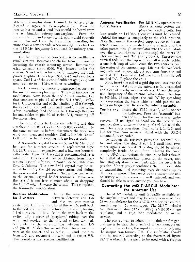
able rrt the surplus store. Connect the battery as in-dicated in figure 26 to receptacle J-1. Press thercceive button and a loud hiss should be heard fromthe combination microphone-earphone. Press thetransinit button and check for r.f. with a field strengthmeter. Do not leave the transmitter operating forrnore than a ferv seconds when making this check asthe 121.5 \Ic. frequencv is still used foi military com-munication.
The first step in the conversion is to modify thetuned circuits. Rernove tl.re chassis from the case byloosening the chassis mounting screws. Remove theu.h.f. detector (type 6050, V-6) located under thechassis. Save the tube for it sDare. Remove tl ie u.h.f.power amplif ier tube (ty'pc 5851, V-4 ) and save for aspare. Coil L-3 of the second dor,rbler stage (V-3 ) rvil lnow rescnirtz to I44 \Ic. u'ithor-rt re-u'inding.
Next, remove the neoprene waterproof cover overthe microphone-earphone grill. This u'ill improve thernodulation. Now, locate the end of coil rvinding L-lthat connects to pin #1 of socket V-l (6050, orcll l"-tor ). Unsolder this end of the u'inding, pull it throughthe e-vclet of the coil form and unrvind three turns.After unn'inding, feed the "r'ire back tlirough the eve-let and solder to pin #1 of socket V-1, trimming offthe excess rvire.
The next step is to locate coil rvinding L-2 thatirttacìres to pin # I of socket V-2 (6050, doubler ). Inthe same manner as before, disconnect the rvire, un-rvind tu'o turns, and resolder. Coil L-3 is left "as is."Coil L-4 m:r1'be removed, as it is no longer used.
A trrursmitter cn'stal betrveen 36 and 37 N,lc. mustbe used for 2 rneter service. A replacement typeCR-14/U crvstal is expensive, and a lorv-cost hermeti-cally sealed trpe F\l-1 crystal is recommended as asubstitute. This cn'stal may be obtained from Inter-national Cn'stal \ lfg. Co., 18 North Lee St., OklahomaCitv, Oklahorna. TIie neu' F\f-l crystal may be se-cured bv l ift inq the old pressure spring and slidingthe nen' crvstal into position. Solder the trvo rviresto thc oriqinirl c'rvstal holdcr terminals. \Iake surethe crvstal is not free to move abor.rt, or droppingthe CRC-7 nriqlrt fr ircture the crvstal. This completesthe t ransrr i i t t t ' r ' r r roc l i f icat ion.
Receiver Modificotion Identif l ' the r.vire runningfor 2 Meters bet*'een detector coil L-5
irnd the transmit - receivesu'itch S-1. t.Ìnsolclt 'r ' tìr is u.irer at t l 're su'itch, pull backto thi: coil, ln<ì uuu'ind one turn from the coil, leavingl-1,/6 trrrns on the l ink. Route thc u'irc bi,Lck to thesrvitch, slip n piece of
"spirghetti" tubing over the
u'ire, and resoldcr to tl ie oriqinirl su'itch terminal.Next, iclcntifr. tì ie s' ire running ltetu'een coil L-5rrnd pin #1 of detc.ctor socket \ '-5. Disconnect thisvvire at the sockct, and as before, r.rnu-ind one turnfrom L-5, rrnd rcconnect the rvire end to socket V-5.Tliis completes the receiver modification.
Antennq Modificotion For 121.5 Mc. operation thefor 2 Meters dipole antenna system em-
ploys trvo loading coils. Forbest results on 144 \Ic., these coils must be retuned.Unfold the antenna completely to the v.h.f. position.Note that one of the vertical support rods of the an-tenna structure is grounded to the chassis and theother passes through an insulrrtor into the case. N{arknear the appropriate coil (on the cap) the letters "A"
(for antenna ) and "G" (for ground ). Unscrerv thevertical rods near the cap rvith a small rvrencli. Solderir one-inch loop of tvire across the two contacts nearthe center of the antenna cap. Lift out the two load-ing coils and remove all but one turn from the coilmarked "G".
Remove all but trvo turns from the coilmarked'A". Replace the coils.
Nor,v, insert the coil of a grid-dip oscillator into theloop of rvire. Nlake sure the antenna is fully extendedand clear of nearby metallic objects. Check the reso-nant frequency of the antenna, rvhich should be closeto 145 N,Ic. If not, t'rdjust the coil "A"
by spreadingor conìpressing the turns which should put the an-tenna on frerprenc,v. Replace the antenna assembly.Testing the Insert the F\{-1 crystal, and connectUnit the batteries. Press the "transmit"
but-ton and listen for the cirrr.ier in a nearbv
teceiver. If no signal is heard on the proper fré-qucnc\/, slou'Ì1' rinscrew thc slug of coil L-l unti l theoscil l irtor stirrts operation. Peak coils L-1, L-2, andL-3 for maximrrm received signal with the URC-4antennir fu l lv extcnded.
To tune-up the receiver, press the "receive" but-
ton and adjust thc slug of coil L-5 until loctrl tu'o-metcr signals are l.reiird. The slug should be almostcompletely inside the coil form. Placing the coveron the URC-4 rvil l dctune the circuits, so Éoles shouldbe drilled at appropriatc plarces in the cover, andfinal slug adjustments nre mtrde after the cover is inposition. Under proper conditions, the unit is capableof trrrnsrnitting and rcceiving over distances up to30 miles or more. Thc porver of the transmitter andsensitivitv of t lre receiver arc u'ell miitched, and votrshotrlcl bc able to u'ork anvone r,ou can heiìr.
Converting the MD-7IARC-5 Modulotorfor Amoteur Use
The \{D-7 rnodultrtor unit is readilv available onthe surplus markct and mrrv bc errsili, converted to a75-u'trtt rnoclulator for thc ARC-S, or other transmitter,mnning up to 150 u'rrtts inptrt. The \,ID-7 includestn'o 1625 modtrlators (12 volt 807's), a VR-150 voltageregulrttor, ancl a 19J5 tone modlrlator for m.c.iv.service.
Tlie ensiest 11';1y to adtrpt the rnodulator for gen-errrl use is to strip the chassis of all components ex-cept thc tube sockets, t l ie input trtrnsformer T-1, andthe outptrt transformcr, T-2. The modulator shouldnorv be rervired according to the diagram of figure28.\ The circlrit is designed to be used v'ith a surnlus

30 Sunpr-us Reoro CoNvnnsrou
T O T R A N S M I T T E R P . A S C R € E N(COMMAi lD SETS ONLT)
Î O T R A N S M I Î T E R P . A P L A Í E C I R C U I '
s + 3 0 0 - 6 0 0 - v o L T s
r 625
AoJUsr Ri FoR 4 voLrs arPlN I oF T1 wlTH i l lcRoPHoNEo u r o F c l R c u / 7 . v a R Y R 1 t oCONTROL GAIN OF M/CROPHON€
K'r',i'o,o* | ílHlrì) l"v"l^tA#lÌl l ' ." t l^\zoF"mío
/ n ì c , u e nK _ 5 4 R E L A I
Figure 29K-54 reloy of BC-442 Antenno ControlUn i t i s mounted on o luminum p lo te .Three cooxiol receptocles ore used forreloy terminols. Coi ls moy be connected
for 6, 12, or 24,volts, d,c.
Figure 28MODIFIED MD-7/ARC-5 UNIT MAKES
MODULATOR FOR AMATEUR USET-I ond T-2 ore originol tronsformers.
carbon microphone, such as the T-17. Adjust the slid-ing tap on the cathode resistor to produce six volts asmeasured across the microphone jack with the micro-phone removed.
Rectifier V-I connected across pins #8 and 9 ofrnodulation transformer T-2 is a
"varistor" that servesas a protective device for the transformer. It is around, red unit with black caps, and is mounted be-side the two large, black 15K wire wound resistors.Pins # I and 3 are atop the modulation transformer,T-2. The empty 12J5 socket can be employed as apower socket.
Converting the Commond TronsmitterReloy for Antenno Chonge-Over UseWhen converting Command transmitters such as
the 'ARC-5" or "BC" series, the antenna switchingrelay is usually discarded. This relay may be adaptedfor either 6- or l2-volt rnobile operation.
The relay (identified as K-54 in the ARC-S units)employs two series-connected coils. The pole piecespull the armature from both directions, so to speak.The armature in turn moves a spiral-wound silver-plated contact between the antenna and ground postsof the transmitter.
Mount the relay on a small sheet of aluminum, asshown in figure 29. It may be placed on one side ofa small chassis-box, Mount the spiral to one SO-239coaxial receptacle, and permit the contact arm tomove between the old contacts which have beensoldered to two SO-239 connectors mounted on eachside of the movable arm,
As wired, the relay coils are connected in seriesand work on 24 volts. To use the coils on 6 volts, wirethe coils in parallel with the magnetic fields aidingeach other. For l2-volt operation, merely connect toone of the coils.
Converting the RM-52 (RM-53)Telephone Unit to o Phone Potch
Two pieces of military telephone equipmentreadily available on the surplus market are the RM-52remote control unit, and the RM-53 control unit. Bothof these units contain a high quality transformer suit-able for phone-patch sewice. The transformer carriesthe military part number C-280A, and the manufac-turer's part number 83718. The transformer has bal-anced 600, 150, 250, and 4000 ohm windings, and iswell suited for many other devices, such as line match-ing, isolation, impedance step-up, etc.
The phone-patch is built in a small aluminum case,and wired as shorvn in figure 30. A simple r.f. filteris placed in series rvith the telephone line to preventr.f. feedback. A d.p.d.t. toggle switch is used to dis-connect the phone line and return the microphone tonormal use. Alrval,s disconnect the patch when it isnot being used.
To use the patch, turn on the control switch andinsert the phone plug in the receiver headphone jack.If your receiver has a 500 ohm output, it can bepermanently connected to the 500 ohm terminals. At-tach your crystal microphone to the microphone jack,and run a shielded line to your speech amplifier. At-tach the phone patch to the telephone line at the baseof the phone. Receiver output u'ill norv pass overthe phone line, and the phone *'ill modulate yourtransmitter.
u r c - c - z a a aT R A N S F O R M É R F R O V R V - 5 2
\ _ _ /2 P O L E , 2 P O S . T O G G L E S W T T C H
Figure 30SCHEMATIC, PHONE PATCH MADE
FROM RM-52 TELEPHONE UNIT

\{eNuer.. Vor,unm III 8l
70 lNSERT
M I X E R T U B E R E C E I V E R I . F C A N
C R Y S T A LM A R K I N G F R E Q U E N C Y
c h A N N E L 1 4 1 5 t . A 5
CHANNEL 45 453.70c H A N N E L 3 2 6 1 5 2 . 7 7
c H A N N E L 3 2 7 4 5 4 . t 6
SCHEMATIC,455 KC
X I . L O w E R c H A N N E L ( s U c H A s 4 1 )X 2 - H T G H E R c H A N N E L ( s u c H a s 4 s )L 1 - L z ' M / L L E R t 2 - c t 4 5 5 K c . t - F
F i g u r e 3 lCRYSTAL FILTER FOR, I . F . A M P L I F I E R
Moke o Single Sidebond Crystol Filterfor Your Receiver with Surplus Crystols!
The type FT-241A crystals (used with the BC-604)are plentiful and cheap on the surplus market. Thesecrystals cover the range of 370 kc. to 500 kc. in 1.85kc. segments. The crystals are used on their 54th har-monic, and are marked 20.0 Mc. to 27.9 Mc. in 100kc. jumps. Other crystals in the same range are avail-able that are separated by a frequency difference of1.39 kc. These crystals are marked 27.0 Mc. to 34.6Mc. (Channels 270-346).
An efficient crystal filter may be made from fourof these surplus crystals. The one stage full-latticefilter is shorvn in figure 31 and may be used in anyreceiver having a 455 kc. intermediate frequencyamplifier. For everyday use it is not necessary tomatch crystals. The filter will greatly increase theselectivitv of the receiver, reducing the interferenceIevel and permitting better reception.
Anv trvo adjacent channels may be used that fallin the i.f. range of the receiver. Channels 44 to 48,and 326 to 330 all fall within the tuning range ofstandard 455 kc. i.f. transformers,
Building the The layout of the filter is determinedFilter by the available space within your re-
ceiver. In general, the filter compo-nents should be mounted on a small aluminum platehaving a small shield across the middle (on both thetop and bottom sides ) to separate the input and out-put circuits of the filter. The filter should be located
Fioure 32THÉ T-23 /ARC-s'V. H. F. TRANSMTTTER
Cooxiol connectors J-30.| ond J-302 ore otupper lef t , with connectors J-307 ond J-309ot bottom of s loping front ponel. R.f . tuningcdjustments of ompl i f ier stoge moy be oc-
compl ished through "door" on ponel.
between the mixer tube and the first i.f. transformercan in the receiver. All interconnecting leads shouldbe kept very short. The lead connecting the mixertube to the transformer is broken. and the filter is in-serted in this circuit as shown in the diagram.
Upon completion, tune a signal generator to thecenter frequency of the filter. (If channel 44 and 45crystals are used, tune the signal generator to 452.77kc. A surplus BC-22I frequency meter will come inhandy). Peak filter transformers L-l and L-2 to thisnew frequency as well as all the i.f. transformers inthe receiver. The insertion loss of the filter is onlyabout 6 decibels, so the addition of an extra tube toboost the gain of the receiver is not required. Thefilter may be used for s.s.b., a.m.-phone, and c.w. re-ception.
ConveÉing the T-23/ARC-5 Tronsmitterto 144 Mc. or 50 Mc.
The T-23/ARC-5 transmitter covers the v.h.f. rangeof 100-150 lr{c. in four channels. It is a companionpiece of equipment to the R-28/ARC-5 receiver. To-gether, these two pieces of equipment make up thev.h.f. portion of the ARC-S radio set. The equipmentis designed to operate from a 24-28 volt d.c. pow-er supply. The T-23 transmitter mounts in a MT-69/ARC-5 rack. Power output of the transmitter is10 watts into a 50 ohm antenna.
The transmitter channels cover the followinq fre-quency ranges:
Channel A: 100-124 Mc.Channel B: 122-146 Mc.Channel C: 122-146 Mc.Channel D: 132-156 Mc.
X r
X r
I
I
_l
X z

32 Sunpr-us Reoro Coxvnnsrox \îe.Nuer,. Voruun III
The crystal frequency is 1/18 of the carrier fre-quency in all cases. Front, top, and bottom views ofthe unconverted transmitter are shown in figures 32,33, and 35, and the schematic is given in figure 34,
Three of the transmitter channels (8, C, and D)u'ill function on 2 meters u'ithout alteration. ChannelA is converted to 50 \Ic. lsix metersl . The tube line-r rp of the t ransmit ter is :
1-f625 (V-301) crystal oscil latorI-i625 (V-302) first harmonic generator1-832A (V-303 ) second harmonic generator1-8324 (V-301) r.f. amplif ier
The porver amplifier is plnte and screen modulatedby the sep:rrate \'ID-7IARC-5 modulator. This unitis shou'n fully converted in another section of this\'lanual.
In order to use the original tubes, a l2-volt f i lamenttransformer is incltrded in the porver stipply unit, TheARC-5 transmitter employs six d.c. relays. These are:
K-30l-Antenna changeover relayK-302-Plate and screen voltase controlK-303-Nfodulator screen and key controlK-304-\lotor tuning controlK-305-Auxiliarl' plate and screen voltage con-
trolK-306-\Iodulator plate and voltage regulator
interlock
All relays except thc antenna changeover unit(K-301 ) arc removed in the conversion. Thc completeconversior.r is outl ined in steps to cnsure that chnngc.sare made properlv irnd ir.r the correct sequence. Checkoff each steD as vou do it.
l-Cut the u'ires going to the coil of relay K-305.Tape the leirds.
2-The rcd,/s'hite u'irer comins from one of theterrninals of K-305 ìs cut, stripped, irnd solderedto the top tcrn'rinirl of rcsistor R-315 (300ohrns ). This resistol is in the cathode circuitof the 832A an'rplif icr' 1\'-301). The top termi-inal lurs ts-o glecn ancl u'hite r.vires attachedto it. Leave these s'ires in position.
3-Rcmove tl ie qrouncl c',,nnr.ct-ion from. R-315.Tlre resistor no\\ ' scr\ '( 's onlr- as rr t ie-point.
-l-Slip the lurge, black 15.000 olinr resistor, R-329(front of chassis ncar 1615 oscil lator socket)olrt of its brackct. Sitve thc rcsistor.
5-Remove the tu'o u'ires from the birck end (to-n'ard the cr1'stirl sockct) of tlrc lrracket. Ttvistthe rvircs together. Thev n'i l l l tc attaclied to aterminrrl strip in a later operation,
fi- lìcmovc R 317 (3,600 ohms-oriuìq(.. bhre', red)fi'om thc' c'ontirct tcrminal of rcltu' K-ll0ll ancl at-terch it to the back cnd of the i;,OOO ohm re-sístor bracket.
7-Ren-rove tìie tu'o leads from the front end of thef5,000 ohm resistor britcket and tie thcn-r to-gcther. Thev u'ill be attaclied to a tern-rinalstrip in a later operation.
S-Ren-rove the green/u'hite rvire from the contacttern-rinal of rcliry K-303 and attach it to thefror"rt encl of thc 15,000 ohm rcsistor brrrcket.
9-Iìt 'plrtc'c thc 15.0ff) ohnt rt 'sistor in tl ic bri icket.10-Rt 'nrovc thc ' t l i rec le ì tvs K-303. K-302, and
K-30i fronr the siclc of the c'l i lssis Do not re-rnrtr.c tìre u'irc.s from the relavs,
Figure 33TOP VIEW OF T-23/ARC-S WITH DUST COVER REMOVED
Amp l i f i e r co i l s o re neo r f r on t pone l , nex t t o t un ing mo to r , w i t h 832 -At r i p l e r o t r eo r . Osc i l l o to r cnd mu l t i p l i e r t ubes o re nex t t o 832 -A ' s . D r i vesho f t f o r r o to ry t u r re t s runs o long the s ide o f omp l i f i e r choss i s . Eoch 832 -A
stoqe mounts in removoble sub-chossis .

Fr eE
' i f i i îs i: a : p r s È
ll ' i l ' #i. rÈp Erpb -
E3
r E; !F O
T
FPfl 3?
;;;
i3lîFF
dLUFF
=v)zú.F
l!
rJ >o L oL l
J L )9rtv
r ! <
ooN
I
F
UF
:LUIUV)
ócoc : r0oo f {@9 rv v \ - v Y . . - n v yO Z t . à r Z € - a Z Z S - B
L .lL tl
r-1 l ' ì 't l r lt r { r - 1 !
: !H,; à'X A f; g Et : g
;s: IE ì F i
;g5lo f o I
er l Ic - - l It r5ó I
LJL-t 600 s t -? r l
tl aI t
__]4-t;tîI -
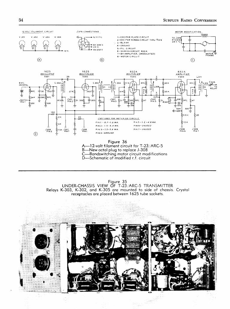
34 Sunpr,us Reoro CoNvunsrox
( A )
1 6 2 5O S C I L L A T O R
v 3 0 l
J 3 N A C O N N E C T I O N S
1 6 2 5MULTI PL I€R
v 3 0 2
@
M O Î O R M O D I F I C A f I O N
'oog
J 3 0 8P I N 7
I M C .CRYSÎAL
J 3 0 7P I N I
R F C
500
R F C
24X
200
J 307P I N 3
J 304P I N 2
J 308P I N 6
F igure 3óA-12-vol t f i loment c i rcu i t for T-231ARC-5B-New octol plug to reploce J-308C-Bondswi tch ing motor c i rcu i t modi f icot ionsD-Schemot ic of modi f ied r . f . c i rcu i t
î îl6?ll - l
J 3 O 7 U S E D F O R M E T E R I
, I - E X C I Î E R P L A T E C I R C U I T
2 - E x c r r E R S c R E E N c r R c u r r r r R u R g r g
3 - B L A N K
4 - G R O U N D
5 - F r L . C T R C U f î
6 . S C R E E N C I R C U I T 8 3 2 A
7 - B + A M P L I F I E R . ( M O D U L A T E D )
A - M O T O R C I R C U I T
8 3 2 AMULT/ PL /E R
V 3 o 3 3
I I a r 2 C 3 a 3
l-PF-íI I
R E L A Y
I=*?,î" *.'
Figure 35UNDER-CHASSIS VIEW OF T-23IARC-5 TRANSMITTER
Reloys K-303, K-302, ond K-305 ore mounted to side of chossis. Crystolreceptocles ore ploced between 1625 tube sockets.
&,il
'*

Mewuer-. Voluun III 35
ll-Install a terminal strip having îive ungroundedterminals in the space left by the removal ofthe relays.
12-Attach the two wires removed in step 5 to oneof the terminals of the strip.
l3-Attach the two wires removed in step 7 to asecond terminal of the strip.
l4-Attach the two solid white wires going to relayK-303 to a third terminal of the strip.
l5-Locate the yellow and white wire going to re-lay K-302. Locate the blue and white wire go-ing to relay K-305. Remove and solder thesewires together and attach to a fourth terminalof the strip.
l6-Locate and remove the blue and white wiregoing to relay K-302. Locate and remove thored, black, and white wire going to relay K-305.Solder these wires together and attach to thefifth terminal of the strip.
l7-Remove completely the red and white wireattached to the coil of relay K-306.
l8-Disconnect the 20 ohm resistor-fuse (R-326),and the red, green, and wlfte wire from theceramic end plate of relay K-306. Solder theresistor and rvire together. Tape the joint.
l9-Cut the other trvo leads going to relay K-306.Tape each end so they rvill not short outagainst the chassis, or to each other.
20-Remove relay K-306 from the chassis. Installa cable clamp to hold the cable next to theside of the chassis. Install a terminal strip withone ungrolrnded tie-point under the relay bolt.
2l-Attrrch the 20-ohm resistor to the tie-point.22-l-308, the 7-pin plug on the rear of the chassis,
should be replaced with an B-prong male plugfor convenience. Remove the rvires one at atime from J-308. Remove the rvire from termi-nal #t and place it on pin #1 oi the tubesocket. Do the same rvith terminal 2. Continuethis procedure until all of the wires are trans-ferred. Remove J-308 and mount the male plugin its plirce.
23-Cut all the rvires connected to relay K-304. Re-rnove from the chassis the 10-ohm resistoriR-330, blou'n, black, black) and the 15 pfd.capacitor associated with K-304. RemoveK-304 from the chassis, and in its place sub-stitute a terrninal strip having one ungroundedtie-point. T:rke the green and white wire fromthe K-304 u'iring cable and attach it to theterminal. Ttrpe the other wires separately forinsulation,
24-Install a lerrd connectins the wires on theterminal strip to terminal 8 of receptacle J-308on the front of the unit.
25-Locnte the tr.vo 0.002 pfd. bvpass capacitors(C-329A, B) at the base of the tuning motor.Disconnect the white lead, leaving the green
and white rvire connected. Tape the whitewire. Short together the two leads comingfrom the motor. The motor windings are nowconnected in parrallel instead of in series. Themotor will norv function on 24 volts. a.c.. rotat-ing the coil nssembly rvhen 24 volts tr.c. isapplied to pin #8 of J-308.
26-Remove the black and lvlrite rvire from thecoil terminal of relay K-301, the antenna re-lay. Ground this terminal. Tape the rvire,
27-'fhe sockets of \/-301 (oscillator) and V-3O4(832-4 amplifier) need not be modified forl2-volt filament operation. On socket V-303,the two solid white wires should be discon-nected and then attached to the terminal thatis occupied by the single black and white wire.The terminal formerly occupied by the twowhites wires is now jumpered to the groundterminal located next to it.
28-Now go to socket V-302 (1625 multiplier ).Remove the green and white wire from pin#7 and solder it to pin #1. Ground pin #7.Check all connections. \Iodification of thetransmitter for 144 NIc. is norv complete. Seefigure 36.
Tronsmifter Modificotion l-Remove tube V-303for 50 Mc. (832-,{ tripler) from
the transmitter. Savethe tube for a spare.
2-Set the transmitter turret on channel D.3-Remove the 20,000-ohm resistors (R-312,
R-313) and the 3 ppfd. coupling capacitors(C-315, C-3f6) from the grid circuit of tubeV-304 (8324 amplif ier).
4-Run a jumper wire from pin #6 (grid termi-nal) of socket V-303 (tripler) to grid pin #6of socket V-304 (amplif ier).
S-Run a second jumper from pin #2 ( grid termi-nal) of socket V-303 to grid pin #2 of socketv-304.
6-Remove coil turret 2-301 (front turret for B32Aamplifier stage). Mark the channel D coil,L-31r-D.
7-Remove the plate circuit winding, and replaceit with 19 turns of #18 enameled wire, close-spaced. Replace the coil in the turret. The 50Mc. conversion is complete.
A crystal having a frequency between 8.334 Mc.and 9.0 LIc. is required for six-meter operation. TubeV-301 is an oscillator doubler, producing output in the17 NIc. region. Tube V-302 is a tripler to the 50 !Ic.region and tube V-304 is a straight amplifier at sixmeters.
It is possible to return to I44 Mc. operation byreplacing the buffer tube and reworking the grid cir-cuit to the original configuration, If two-band opera-tion is desired, there is no reason why a plug-in boardcould not be adapted to replace the 832A buffer, in-
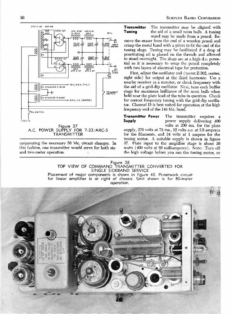
36 Sunpr-us Ranro CoNvpnstoN
Figure 37A.C. POWER SUPPLY FOR
TRANSMITTERT-23lARC-5
corporating the necessary 50 Mc. circuit changes. Inthis fashion, one transmitter would serve for both six-and two-meter operation. .)
Tronsmitter The transmitter may be aligned withTuning the aid of a small neon bulb. A tuning
wand may be made from a pencil. Re-move the eraser from the end of a wooden pencil andcrimp the metal band with a pliers to fit the end of thetuning slugs. Tuning may be facilitated if a drop ofpenetrating oil is placed on the threads and allowedto stand overnight. The slugs are at a high d.c. poten-tial so it is necessary to wrap the pencil completelywith two layers of electrical tape for protection.
First, adjust the oscillator coil (turretz-3Ù2, center,right side) for output at the third harmonic, Use anearby receiver as a monitor, or check frequency withthe aid of a grid-dip oscillator. Next, tune each bufferstage for maximum brilliance of the neon bulb whenheld near the plate lead of the tube in question. Checkfor correct frequency tuning with the grid-dip oscilla-tor. Channel D is best suited for operation at the highfrequency end of the I44lvlc. band.
Trqnsmitter Power The transmitter requires aSupply power supply delivering 400
volts at 200 ma. for the platesupply, 270 volts at 75 ma.,12 volts a.c. at 2.5 amperesfor the filaments, and 24 volts at 1 ampere for thetuning motor. A suitable supply is shown in figure37. Plate input to the amplifier stage is about 30watts (400 volts at 80 milliamperes). Note: Turn offthe high voltage before you run the tuning motor, or
uTc s- 40 250 MA.
urc s-312 0 H
3 0 H 3 0 HUTC S-27 UTC S-27
(FrL.)
rre400 v
2OO MA
T R A N S M I Îs w f T c H
R Y I
B+270V.
TOP VIEW OF
Plocement of mojorfor l ineor ompl i f ier
Figure 3BCOMMAND TRANSMITTER CONVERTED FORSINGLE SIDEBAND SERVICE
components is shown in f igure 40. Pi -network c i rcu i tis ot r ight of chossis . Uni t shown is for BO-meter
*îiidoperotion.

MANuel, Vor-uvrB III 87
it is possible to blow out the 47-ohm resistor (R-316)in the 832-A plate circuit.
Convert Your BC-458 Into oSingle Sidebond Tronsmitter!
The BC-458 is part of the SCR-274N radio equip-ment. It is a compact v.f.o. transmitter, covering
the range of 5.3-7.0 Mc. (Navy version is theT-2flARC-s). Four tubes are used in the transmitter:1626 oscillator, 1629 "magic-eye" tuning indicator, andtwo 1625 power amplifiers.
This Command transmitter may be easily con-verted to a phasing-type s.s.b. transmitter for either
AUOIO ORIVEP
v3
! . rz tv t 9 MC. OSC.
(sEE rExr, Vzsc1 S eaut
ear,a_R i l o K
6 A L 5
6 A L 5
9 MC. AUP,
I 2 8 A 6
9 MC.
La
I BC.
L 5
9 HC.
L 6
î î| /-----------\ It P 9 lt - l
5
r 2 u t - B r A s
Figure 39SCHEAAATIC, SINGLE SIDEBAND TRANSMITTER
I
9!ZL 6 J z
AALANCEO UODULATON
C-ì-3 ppfd. This copocitor moy not benecessory. Leove it out unless cor-rier bolonce con not be set withslugs of L- l ond L-2.
C-2-Originol osci l lotor tuning copoci-tor, ponel-dr iven
C-3--Originol osci l lotor poddíng copoci-tor
C-4-See coi l tobleC-5, C-ó-140 ppfd.C-7-1250 volt mico podding copocitor,
3 0 0 - l 5 0 0 p p f d .C-BA-B-C-D-ì 0-ì 0-10-10 pfd. electro-
lvt ic in metol con.
FL-l-Borker & Wil l iomson type 350phose-shift network.
T-l-20K to ó00-800 ohms. ThordorsonTR-Ì7, or Arrow Soles Co. type TR-29.
T-2, T-3-l5K to 200 ohms. ThordorsonTR-25, or Arrow Soles Co. type TR-29 (use Yz of secondory winding).
RFC-l-2.5 mh. chokeRFC-2-5 turns #18 e. wire oround 47
ohm, 2-wott composition resistor.RFC_3_2.5 mh. ,,tronsmitting type,,
chokeSee figure 43 for coil dota
B l z 5 o M A .P I L O T L A M P
TII0
6 N D .
, r i - , o r r * * , ^TW- ZSii: L_'-r
.or f625 RFc3 v E

3B Sunpr.us Raoro CowvBnsroN
80- or 4O-meter operation. Either sideband may betransmitted, and the completed transmitter includes ahigh stability v.f.o. Peak power output is about 100rvatts rvhen a 1000-volt plate supply is used.
The Sidebond The complete circuit of the convert-Circuit ed command transmitter is shown
in figure 39. The original oscillatortube and circuitry (V-10) is retained, as well as the1625 amplifier tubes and sockets (V-8, V-9). Thesideband signal is generated at a crystal controlled fre-quency of 9 Mc. Tubes V-1 and V-2A are the audiostages that develop sufficient voltage from a crystalmicrophone to drive phasing network FL-l prop-erlv. The two irudio output signals from the net-work are further amplified by tube V-3 and appliedin series with the r.f. output of the 9 Mc. crystaloscillator through circuits ^12-LL
and T3-L2. Twor.f. signals are available at points "A"
and "8". Eachsignal is amplitude modulated, but of a different r.f.phase. These trvo signals are applied to the diodebalanced modulator (V-4, V-5) through two balanc-ing potentiometers, R-2, and R-3. The signal de-veloped in the output circuit of the balanced modula-tor (L-4) is a single sideband signal at 9 N{c. The ac-tion of the modulator has balanced out the carrierand one sideband, leaving the desired single side-band. Reversing switch S-1 will change the sidebandappearing at the output of the balanced modulator.This signal is amplified by V-6.
The 9 NIc. signal must now be changed in fre-quency by a mixing process to the desired output fre-quency in either the 8O-meter or the 20-meter band.This is done by combining the 9 Mc. sideband signalwith the 5 ìvlc. output signal of the variable fre-quency oscillator, V-10. Mixing is done in tube V-7.Twenty-meter output is a summation of the two sig-nals (9 Mc. plus 5 Mc. - 14 Mc.) and eighty-meteroutput is the difference of the two signalp ( 9 Mc.minus 5 Mc. - 4 Mc.). Both signals appear in theplate circuit of Y-7, and the desired signal is obtainedby tuning the circuit C-4-L-7 to either 20 or 80 meters.Data for this circuit for either band is given in figure43,
The final step is to amplify the s.s.b. signal to ausable level. This is done in the linear amplifier,V-8, V-9. When operated at 1000 volts plate potential,s.s.b. peak output is over 100 watts, dropping to 20watts at 300 volts. The transmitter is placed on theair b,v energizing V-7 when switch S-2 is closed.
V.f.o. operation is obtained by tuning capacitorC-2. The range of 5.0-5.4 Mc. covers the 20-meterband (I4.0-I4.4 Mc.), and the range of 5.2-5.0 Mc.covers the 8O-meter band (3.8-4.0 Mc.). It is a sim-ple matter to increase the setting of the oscillatorpndding carpacitor C-3 to lower the oscillator fre-quency to 5.0 Mc. at the low frequency end of thedial.
Converting the The first job is to strip theCommond Tronsmitter Command transmitter of
all the parts you do not re-quire. Refer to figure 2 for rviring diagram of orig-inal transmitter. Remove rill of the original wiringbelow the chassis except the 1616 oscilÉtor circuiiRemove R-71, C-64, C-66, K-53, C-62 and R-76, Alsoremove C-65. Leave crrpacitor C-Gl. The amplifiercapacitor (C-67) of the tuning gang is removed, anda new tuning shaft for oscilltitor tuninq capacitor C-63is made from the knob and sh,rft fròm ihe variabÌelink coupling coil above the chassis (part of T-S4).Above the chassis, the loading coil, anteìna relav. andplate coil T-54 are removed.
The new parts, tube sockets. rrncl other com-ponents are now laid out atop the chrrssis, as shownin figure 38, and the chassis is drilled. A nerv alumi-num panel is placed over the old front panel of thetransmitter. At the rear of the chirssis rr miniaturecoaxial receptacle (J-2) is mounted, and the originalpower plug is removed and an 8-pin socket ,,ìbrti-tuted. Also mounted on the bacli apron is a hishvoltage terminal (Millen). Placemeni of t lre com-ponents is indicated in figures 40 and 41.
Wiring the S.S.B. The fi lament circuits are wirer-lTronsmitter first. Next, the oscillator coil
( L-3, figures 39 and 40, olclT-53, figure 2) is rvired. Terminal #5 of L-3 is at-tached to capacitor C-61, and the opposite termínal
V 6I 2 B A 6
v 1 1 2 4 T 7A U O I O
v 3 , 1 2 A U 7 V 2 , 1 2 A U 7A U O C D R V E R A U O ] O , X T A L O S C
n À S ! S . I O P v t E W
F iqu re 40Plocement of poi ts on chossis , top v iew
A C E M E N T O F P A R Î
F i g u r e 4 lPonel loyout ond coi l connect ions, L-3
t_ T_ r_l r t L t 2 3r r l
/ 1 6 2 5 \ / \\ v8 , / t - a - / -
C O N N E C T I O N S , L 3
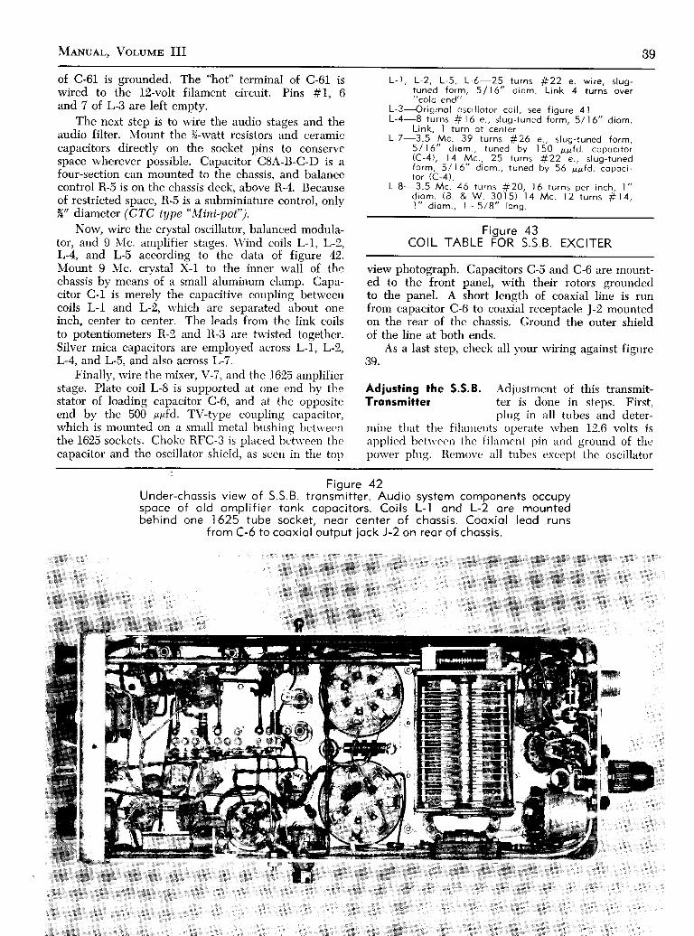
Menual, Vor-ulrr III 89
of C-61 is grounded. The "hot" terminal of C-61wired to the l2-volt filament circuit. Pins #1"and 7 of L-3 are left empty.
The next step is to wire the audio stages and theaudio filter. Nlount the )í-watt resistors and ceramiccapacitors directly on the socket pins to conservespace wherever possible. Capacitor C8A-B-C-D is afour-section can mounted to the chassis, and balancccontrol R-5 is on the chassis deck, above R-4. Becauseof restricted space, R-5 is a subminiature control, onlyX" diameter (CTC trJpe "Mini-pot").
Now, wire the crystal oscillator, balanced modula-tor, and 9 ,Vc. amplifier stnges. Wind coils L-L, L-2,L-4, and L-5 according to the data of figure 42.Nlount I IvIc. crystal X-1 to the inner wall of thechassis by means of a small aluminum clamp, Capa-citor C-I is merely the capacitive coupling betweerrcoils L-l and L-2, which are separated about oneinch, center to center. The leads from the link coilsto potentiometers R-2 and R-3 are twisted together.Silver mica capacitors are employed across L-I, L-2,L-4, and L-5, and also across L-7.
Finally, rvire the mixer, V-7, and the 1625 amplifier'stage. Plate coil L-8 is supported at one end by th.estator of loading capacitor C-6, and at the oppositeend by the 500 ppfd. TV-type coupling capacitor,which is mounted on a small metnl bushing betq'ee'nthe 1625 sockets. Choke RFC-3 is placed beiu een thecapacitor and the oscillator shield, as seen in the ton
L-' l , L-2, L-5, L,é-25 turns f i22tuned fo rm, 5 / ì ó " d iom. L ink"cold end"
L -3 - - -O r i g i no l osc i l l o t o r co i l , see f i gu re 4 lL -4 -8 t u rns $ ìó e . , s l ug - t uned f o rm , 5 /16 " d i om.
Link, I turn ot centerL -7 -3 .5 Mc . 39 t u rns f i 26 e . , s l ug - t uned f o rm ,
5 / | 6" d iom., tuned by ì 50 ppfd. copoci torr c - 4 ) , l 4 M c . , 2 5 t u r n s # 2 2 e . , s l u g - t u n e dfo rm , 5 /16 " d i om. , t uned by 56 pp fd . copoc i -t o r (C -4 ) .
L -8 -3 .5 Mc . 46 t u rns f t 2O , l ó t u rns pe r i nch , l "d i o m . ( 3 . & W 3 0 ì 5 ) 1 4 M c . 1 2 t u r n s r t 1 4 ,l " d i o m . , | - 5 / 8 " l o n g .
FigureCOIL TABLE FOR EXCITER
view photograph. Capacitors C-5 and C-6 are mount-ed to the front panel, with their rotors grounde<lto the panel. A short length of coaxial line is runfrom capacitor C-6 to coaxial receptacle J-2 mountedon the rear of the chassis. Ground the outer shieldof the line at both ends.
As a last step, check all your wiring against figrrreJì ' .
Adjusting the S.S.B. Adjustment of this transmit-Tronsmitter ter is done in steps. First,
plug in all tubes and deter-mine that the fi laurents operate rvhen 12.6 volts isnpplicd bets'ecn thc fi lrrmcnt pin and ground of theporver plug. Rcmove all tubcs except the oscillator
is6
e. wire, s lug-4 turns over
43S S . B
Figure 42Under-chossis v iew of S.S.B. t ronsmit ter . Audio system components occupyspoce of o ld ompl i f ier tonk copoci tors. Coi ls L- l ond L-2 ore mountedbehind one 1625 tube socket . neor center of chossis . Cooxio l leod runs
f rom C-ó to cooxio l output jock J-2 on reor of chossis .
w#I
IItI
t
im;
:ti::ta::ii:.l

.{0 Sunpr-us Ranro CoNvpnsroN
tube V-10 and the regulator tube, V-11. Apply 300volts to the trtrnsmitter and check v.f.o. operation bylistening to the 5 \{c. region in a nearby receiver.Acljust capacitor C-60 (atop the chassis, see figure 2)to bring tlie 5,3 \Ic. dial point down to 5 Mc. Now,plug in tube V-2 and listen at I Mc. Adjust the slugof coil L-2 until the crystirl stage oscillates.
Yon norv nced an nudio oscillator for the next acl-justment step. A high quality, low distortion oscilla-tor (such as the Heathkit AG-10 or AG-9A should beemploved ). A lorv level, 1200 cycle audio signal isinjected in microphone jack J-1. Coils L-4, L-5, andI-6 are peaked for maximum 9 Mc. signal as measuredu'ith :r viÌclrum tube voltmeter connected from pin#5 of socket V-7 to ground, or with a antenna leadof a nearby receiver held close to pin #5.
As lone as the audio signal is applied, a signalat thc sidcband fre<ltrencv u'ill iìppeitr in circuit C-4-L-7. [,et us iìssrlme, iìs iul example, that this circuitis tlrned to B0 meters. Tune your receiver to 80 metersand listen for the signal. You will hear a signal,modulated s'ith thc 1200 cycle tone at a frequencvthat is the difference betu'een 9 lvlc. (the crystal fre-rluency,) and the frequencv of the v.f.o. Adjust L-7for maximum signril. Next, turn off the audio signal,and adjust carricr baltince potentiometers R-2 andR-3 for rninimum signal.
Tlie audio baliurce controls and coils L-l andL-2 irre best adjusted rvith the aid of an oscilloscopeusing "rippler" ptrtterns. These adjustments are cov-ere'd in detail in the Reoro l{-lroeoor ( nublished bvEdi tors rLrrd Errg incc ls . Srrmmcr lLrnd. Crr l i f . ) . or in theHirndlrook Singlc Sídcbund for Radio Amateurs, pnb-lisl ied br.t lre Amcrican Radio Relay League. In brief,t l ie ve'rt ic'al pli i tcs of t l ic
'scope tube are l ink-couplcd
to coil L-ti, and oscillator tube V-10 is removed. leav-ing onlv thc 9 N{c. signal input to V-7. The 'scope
pattern u'ill have :i modulation "ripple" upon it.
Listening to the 9 \Ic. signal in a nearby receiver rvillallow you to l"rear the 1200 cvcle audio tone impressedupon the speech svstem. During adjustments, theaudio level should be helci irs lou' as possible to pre-vent overloading the phasing svstem of t l ie transmit-ter. Couple tlie rcceiver to coil L-6 and leduce thegain to prcvcnt overloacling. \rxr', adjust balancecontrols R-5 and R-4 for milin'nrnt "ripple"
on thc'scope patteln. AIso adjust the slugs of coils L-l and
L-2 for minimum ripple. Kecp the audio level aslow as possible, trnd go over the adjustr.nents severaltimes. Also rebalance the cirrrier ltalar-rce controls R-2and R-3 for minimum pattcrn. lìeve-rse sidebandsrvitch S-1 rrnd recheck 1'our adjustntents. You shoulclstrive to obtain minimum "ripple" rt 'qrrrclless of thesetting of srvitch S-I. Once this poirrt hirs beenreached, disconnect the audio qcnerrìtor and
'scope
and connect u microphone to J-1. You should hear aclean s.s.b. signal at 9 \,Ic.Lineor Amplif ier Plug in the 1625 tubes and applvAdjustment about -18 volts bias (use flash-
lislrt batteries or small "C" bat-teries ) and jurnper high voltage tern'rinal P-l to tt:e250 volt supply, plrrcing 250 r,olts on the plate circuitof the tubes. Resting plate current n'ill be about 90milliarmperes or so. Unbalance carrier control R-2 orR-3 and you rvill obtain an B0-meter carrier in theplute circuit of the linear stage. You cAn no\\r resonateiurd tune this stiige like anv otliel amplifier. For B0-mcter opcration, cirpircitor C-7 n-mst be placed acrossthe output jack J'2. Thc vlluc of t lr is c' irpircitancedcpcnds upon tlre ir.npeclrrnce' of t l ie i intenua svstem,iind rvill varv betrvee'n 300 rrpfd. nnd 1500 ppfd. As astarter, parallel tn'o scctions of a broirclciist-tvpe vari-able capacitor and use it for C-7. Sct it irt maximumcapacity.
Figure 44,,COMMAND"
TRANSMITTER MAYEASILY BE
CONVERTED INTOH I G H P O W E R S . S . B .L I N E A R A M P L I F I E R
250 wotts peok power isrun by inexpensive ìó25tubes (center). Voltogeregulotor tubes ore ot
reor of chossis.

MeNuer-, Voluur III 4l
After vou havc become familiar rvith operation at250 voìts, voLr can boost the plate voltage to 1000 voìtsor so. Tl-re bias voltage for the 1625 tubes should berrrised until the no-signnl pl:rte current is about 35ma. at 1000 r'olts. For other plate voltage values, thebias should be adjustcd so that the product of thevoltiìge and the no-signal plate current results in apo\\,er inpr-rt of 35 s'atts to the tl'o tubes. Under fullvoice input signal, tl're plate current r,vill kick up to120 mill iamperes ol so.
Conver t Your Commond Tronsmi t ter to oS.S.B. L ineor Ampl i f ier
The Command transmitter n,akes an excellentlincar rrmplifier for ,10- or S0-mcter operation, capableof lunning rr peak po\\'er input of 150 t'atts. It makesa good linear amplifier for the l0A or 20A sidebandc'xcitcr, or for any s.s.b. excitcr ciipable of deliverinq afeu' n'irtts of porver in the 40- or 60-meter amateurbnnd.
For S0-rnetel opcr:rt ion, the 3-'1 \lc. (BC-696, orT-19 ARC-5) or t l ic "1-5.5 \ lc . (BC-457, or T-20 'ARC-5) trirnsmittcr mriv be usecl. For 40 rneters, the5.3-7 \ lc . ,BC-,158, or T-21 ARC-5) or t l re 7-9.1
Fiqure 45S C H E M A T I C , S . S . É . L I N E A R A M P L I F I E R
MADE FROM A "COMMAND"
TRANSMITTERC- l-300 ppf d. Bud MC- I Bó0L-l-Adjust to tune to output frequency with
C - l n e o r l y f u l l y m e s h e d . A i r - D u x ì ó . l 0 ,or B&W 3907-l coi l stock (2" diom., l0tu rns per inch) . Ad lus t on tenno top fo rop t imum lood ing
RFC- l -2 .5 mh. choke " t ronsmi t t ing type . "
ffi
Fígure 46U N D E R - C H A S S I S V I E W O F S . S . B . L I N E A R A M P L I F I E R
Screen res is tor R- l is mounted to reor of chossis obove the vol toge regulotortube socke ts . P lo te t un ing copoc i t o r C - ì i s od j us tob le t h rough s ide o fchoss i s . Sh ie lded w i re i s emp loyed fo r f i l omen t , sc reen , ond b ios l eods .Tuning copoci tor neor d io l is not used, serv ing only os o beor ing for
extension dr ive shof t .

42 Sunplus Ranro CoNvensroN
VIc. (BC-459, or ^î-22,1ARC-5) transmitter may be
used. Power requirements are 12.6 volts at 0.9 am-peres, 350 volts at 35 ma., and 500 to 1000 volts at150 ma. plate potential.
Conversion to S.S.B. This conversion entails theService removal of the oscillator and
auxiliary equipment, and theconversion of the oscillator coil to form an amplifiergrid coil. Voltage regulator tubes are added to thescreen circuit of the final amplifier. A new amplifierplate circuit is also required.
The first step is to remove the unwanted com-ponents. Beneath the chassis, remove R-71, C-58,C-64, and all small components on the three rear tubesockets. Remove R-75, R-76, and auxiliary paddingcapacitor C-67. Remove relay K-53, and resistor R-78.Above the chassis, remove the antenna relay K-54 andthe loading coil. Remove the plate coil T--54 and therotary link control. Remove all loose leads andrvires.
Wiring the A schematic of the convertedLineor Amplif ier Command set is shown in figure
45, and top and bottom photo-graphs are given in figures 44 and 46. A five-prongsocket replaces the rear power receptacle, J-64. TheVR-150 and VR-105 regulator tubes are placed rntwo empty octal sockets at the back of the chassis.
Tap #1 on the old oscillator coil (T-53) is userlas the r.f. input circuit for the amplifier. Excitationmav be controlled bv tuning the main dial o{ thetransmitter for greatest grid drive. The plate circrritof the linear amplifier uses a new tuning capacitor,C-1. The old, ganged capacitor is not used, but isretained to act as a bearing for the oscillator tuningshaft.
Plate coil L-l is mounted above the chassis asseen in figure 44. It should be pruned so that reson-iìnce on 80 meters occurs with C-l almost fuJlvmeshed, and 4O-meter resonance occurs with C-laboutTí% meshed. The antenna tap on L-l is connect-ed to a coaxial receptacle mounted on the front pancl
of the amplifier. An external 0-250 ma. d.c. milliam-meter may be placed in the B-plus lead for tune-uppurposes. Pins #6 and #7 of each 1625 socket arègrounded to the metal shell, and the "hot"
filamentline is bypassed with a 0.01 r,fd. ceramic disc capaci-tor, Pin #3 of each socket is also bypassed to themetal shell with a similar capacitor.
Lineor Amplif ier Bias voltage is applied to theOperotion amplifier, and the
- B-plus lead
is temporarily connected to the350 volt_ supply for tune-up purposes. Bias voltageis varied (about -18 volts) untíl the no-signal platecurr-ent oJ the amplifier is about g0 milliamperes. Asmall s.s.b. signal is applied to the input and the tun-ing dial varied until a rise in the plate current of theamplifier is noted. It may be necessary to adjust pad-ding capacitor C-60 or the slug of coii T-53 io obtainresonance. Plate tuning "apacitot C-l is tuned forplate circuit resonance, and the tap on coil L-l is ad-justed for optimum antenna loading. Resistor R-lshould be adjusted for about 30 ma. oif regulator tubccurrent. When the amplifier is operating properll,,the 1625 plate voltage may be raisèd to a maximumof 1000 volts. Bias sliould be adjusted to provide ano-signal plate current of about 35 ma. únder fullexcitation, maximum average plate current rvill beabout 125 ma., providing a s.s.b. input signal of about300 peak watts. The antenna tap on coil L-l may bereadjusted at the higher value of plate voltage foroptimum antenna loading.
Using the Western Elect r ic7Ol-A Terrode
The large \Vestern.Electric 701-A tetrode is avail-able on the-surplus,market for a lou,pricc. The phy-sical size of the tube (Tó" high, 4t!,' diameter) ìug-gests that it rvould make a good high po\\'er r.î. aÀ-plif ier. The tube is a tetrode intenclecl for ltLrlse modu-lator operation. It has an indir.ectlr ìteatcd cathode.rví th t l rc p l i r te termin i r l o f the t r rbe . r t t l re ton of theglass bulb. Connections to the terminirls and theoutline of tlie fube are shou'n in figure -17. A modifiedWestern Electric 153A socket mirv bc rrsed, or theexperimenter can easily bnild his ou'n socket, ,The
tube should be mounted in a r.crticrrl position, andthere should be a free circrrlr it i 'n of ir ir around theglass envelope.
The pulse modulator ratinqs of t l.re tube are:Heater \-oltage. 8.0 r.olts. ir.c. or d.c.Heater Current, 7.5 arnpe'res.N'Iaximum plate voltiree (ptrlse), 12,b00 volts.N,Iaximum screen voltagc , 'pulse), 1,200 volts.Average plate currcnt (pulse), B0 ma.Peak pulse plate currcr.rt, l0 amperes.Plate dissipation (pulse ). 100 rvatts.Screen dissipation (pulse), 15 rvatts.The suggestt:d cli iss-C operating conditions for
amateur service are:
2l3 2
Figure 47OUTLINE DRAWING OF W,E . 70 I -A
VACUUM TUBE, SHOWING TERMINALCONNECTIONS
t tor 'C , .o ' ,n
l l[
" ' "^- ' ]
\ (ì+. r- l
H t I#^ "^U U U T T E I
> . i 6 M A X
6 0 0//,-*EAîER
/ / / - -<6\\ . \ \/ / / " \ \ \ G R | D \l l L t e . t d ' l t 9 ' � ll t r " Y / ] 1 |
G F j D \ \ \ \ . ^ ' / . " l"' \\--1l'� /\ v - H E A r E R - /
6 0 0
, * ' F - , /
g O T T O M V I E W

MeNueL, Volunan III 4iìI _ B A N D S E C T I O NG _ B A N D S E C T I O N
f E R M I N A LS T R f P
Figure 48SCHEMATIC, MODIFIED BC- I 253
METEOROLOGICAL TRANSMITTER
Filament voltage, 7,5 volts.Filament current, 7.0 amperes.Plate Voltage 2000 2500 3000 3500Plate current 350 300 250 250Power Input 750 750 750 875Plate dissipation 220 200 f60 L75Screen voltage 400 400 400 400Screen current 40 40 40 40Screen dissÍpation 20 20 20 20Grid voltase -150 -150 -f50 -150
(volts)( *a.(watts(watts(volts( ma'( watts
( * u . )used as afrom ex-
(vol tsGrid current 1,5 t5 15 15Note: It is suggested that a 6Y6-G be
screen clamper tube to protect the 701-Acessive screen dissipation.
Inter-electrode capacitances :InputOutputGrid-plate
15.6 ppfd.8.5 r,pfd.
0,16 prfd.
Converting the BC-l253 to oSensitive Rodio Control Receiver
The BC-1253 meteorological transmitter, availablein quantity in the surplus stores can easily be con-verted to an excellent radio control receiver, featuringhigh sensitivitv, good stabiìity, and light weight. Thereceiver is suitable for use in model airplanes, boats,etc. The BC-1253 r'"'as originally used inlveather bal-loons to send upper-:rtmosphere r,veather informationback to earth. Tlie transmitter is contained in a smaìI.strong cardboard box that is attached to the soundinqballoon. A lightweight battery pack accompanies thetransmitter on its flisht into the heavens.
The BC-1253 emplovs a single 955 acorn triodetube as a milliwatt oscillator, ivith the socket of theoscillator built into the end of a silver-plated tankcircuit. The converted circuit of the oscillator isshorvn in figure 48. Note that the only steps necessaryfor the conr.'ersion are to remove the unnecessary com-ponents, chtrnge the value of the 955 grid resistor, andmake the rviring changes shown.
Conversion to o Rodio The original transmitterControl Receiver circuit uses several con-
nections on a socket stripthat it is mounted on. All connections to this strip areremoved. To do n neat job, the contact pins should be
- 1 . 5 V . + 1 . 5 V . - 1 3 5 V . + 1 3 5 V
Figure 49S C H E M A T I C , M O D I F I E D B C - I O ó ó I . F . F ,
TEST SET
drilled off and the space provided used to mount theadditional parts. It is necessary to add a 3-30 ppfd.variable compression trimmer capacitor across thetuned circuit line. It will be necessary to slide thetrimmer up and down the lines while adjusting thecapacitor to hit the 2 meter ( 144 lvlc, ) amateur bancl.Varying the antenna tap and the tuning capacitor willpermit the detector to remain in oscillation across thecomplete band.
A super-regenerative detectol circuit is employedfor maximum sensitivity. For optimum results, theplate circuit relay ( Sigm:r t,vpe 4F ) should be set topull in rrt 1 milliampere of plate cr-rrrent. This can bechecked by connecting the relav coil in series rvith a50K potentiometer, tr 45 volt battery', and a milliam-meter. Adjust the point spacing of the contacts andthe spring tension so that the relay pulls in at aboutI milliampere, nnd drops out at about 0.8 ma. Nolv,insert the relay birck into the receiver circuit and ad-just the variable plate voltage control until the relavpulls in. Next, back off slightly on the control untilthe relay drops out. A nearbv 2-meter r.f. signalpicked up by the receiver should now cause the relayto pull in. Adjust the irntennil tap for maximum re-ceiver sensitivitv.
Converting the BC-l06ó to o144 Mc.-220 Mc. Receiver
The BC-1066 Test Equipment is a dual v.h.f. oscil-lator intended to check the operation of the SCR-695*I.F,F." radio equipment. The BC-1066 consists of two
6 7 . 5 V
lrlrlr
6 - A A N D é I - a A N O
1 D 8 G T / G. o 1 ! F 1 0 0 ! ! F

44 Sunprus Raoro CoNvnnsrox
IIt cl 5 l
t o 2
IST MULT
54.7-74.7UC
zND. MULT
I S T O E T E C T O R
A N T E N N AC O U P L I N G
ANTENNA
2 N D I A M P L I F I E R
A N T E N N A T U N I N Gt - S l O 3esf- -
c t 0 6utaF
aII
i 5 l
l l
! ;r l
t i6 0 i 6 0 M c
t l
f ì l -I t l o
a t -- J
K r o 4
6;q}{\ ì; el es b
TCr04=.o02
c r 8 0.o02
PANELG R O U N O
M E T E R / S t O t /s w r r c H
R F A M P L I F I E R
trlrîq)oìoA
Eo
!a,IE
E0I
Eogloi5
a\Y
II
3 R D I F A M P L I F I E R
afltioMMf-
(I
Ò
Ic rso [ooos souètcx sf NS/T/v/Ty ppf ss cp cuT seuELcH
F igure 50SCHEMATIC, NAVY TYPE COL-430ó5 (MBF)
TRANSMITTER-RECEIVER
'::oo2
M E T E Rll 'dl l +tl-o t
J t o z /
rî)\-/ier ì
eo: aov cl$
E J NeF TuI f-^' -l
R ro4 Rro53w 2 .4
fo
---c i l 2
touuF
r A L K
PELf ASEro
L / S T E N
, ,1
l o Pt \ ;
I/ 1 !13
ì
:
6CA I, v l t 4 L * c >
osc I s,o: l a
R E C E I V E RCR Y STAL
R r 4 42.4 Rtrt z2oo L -

MeNuer., VolulrE III 45
6AQ6v t 0 5
V O L U M EI A F O R I V E R A F P O W E R A M P L
--+-l s,3è
trl
0,0ìE'q
Eo
È s r v c2 N D D E T E C T O R
6 C 4v i l 6
q,fE
oU
Eogì
.9o
c t 4 ?.otI
I
= l c tl .o l
? 5 2 6v r r E
8 6..trT
R r 3 6
s r o li l 5vACi l 5 v D CJ r o 4
oz
I
úzù<
F igure 50SCHEMATIC, NAVY TYPE COL-430ó5 (MBF)
TRANSMITTER-RECEIVER
TU(\/! ì(J
R E C T I F I E R S
P O L A R I T Y R E C T T F I E R S6 C 4
t5 vl ic 7
nrao Èv*
v l l 6 v l 2 3 v l o s v l o 6 v t 0 2 v r o 3 v r o r v t 2 4 v t 2 2 v i l 5 v i l 7 v i l 4 v l t 3
HANOSET THEMATIC
(voruue coNraou)I O N - O F F
c r 5 7.oo 2
E X T E R N A L A U O I OJ r o 5
N O Î E : U N L E S S O T H E R W I S E S P E C I F I E D :A L L R E S I S T A N C E V A L U E S A R E I N O H M S ,CAPACITANCE VALUES ARE IN MICROMICRO.FARAOS ANO INOUCTANCE VALUES ARE INH E N R I E 5 .
cte6 fgoos

46 Sunpr,us Ranro CoNvnnsrox
super-regenerative detectors, tunable over the twoI.F.F. bands. The weak pulses of the detectors werepicked up by the I.F.F. set, which responded by re-turning a series of coded pulses which could be heardby the receiver portion of the BC-1066. This inexpen-sive surplus item consists of two type 957 acorn triodetubes used as v.h.f. detector-oscillators, and a 1D8-GTaudio amplifier. The two tuned circuits are tunableover ranges close to the I44 Mc. and 220 Mc. amateurbands. A panel srvitch (I-band: G-band) selects theaudio output of either detector. The audio is ampli-fied by the IDB-CT tube.
Conversion to o The BC-1066 can be converted toV.H.F. Receiver a sensitive receiver for the ama-
teur 144 Mc. and 220 Mc. bands.The original circuit of the unit is shown in figure 49.It is only necessary to unground the end of each r.f.choke in the 957 circuits. In series with this choke,connect a 10 megohm, )l-watt resistor to ground,
The G-band receiver can be tuned up to the 220N{c. band by adjusting the padding capacitor, and theI-band receiver rvill tune to 144 Mc. rvith a simpleadjustmcnt of the padder capacitor. The BC-1066draws onlv a small amount of current, and a size Dcell, plns trvo small 67)í-volt batteries rvill last for manymonths. It is an excellent receiver for "Field Day"or iìny porterble v.h,f. use. Trvo )í-rvave whip antennasmounted ntop the case and link coupled to the respec-tive tr-rned circuits rvill be satisfactory for portablervork.
Conversion oÍ R-9/APN'4 forI l5 Volt A,C. ó0 Cycle Operotion
R-9/APN-4 makes a good 160 meter receiver whenconverted for 50-60 cycle operation. The receiver op-erates on four preset channels, any one of rvhich canbe selected by the main channel switch. In this conver-sion, the power supply is adapted for operation fromyour light line, and the receiver is modified for opera-tion rvithout auxiliary equipment. The 1400-volt supplyin the receiver for the Loran'scope tube is not used.
Receiver Section Check off each step as you do theConversion conversion.
l-Remove J-f04 (red) from thepanel and install a phone jack in its hole. Solderthe center u'ire of the coaxial cable to the tip con-nection of the jact<.
2-Rerr-rove the rvires from the "Filter In-Out" srvitch.
Splice the rvires together near the 6SL7 socket.Tape the rvire joint,
3-Cut arr'i,ry the rvire betrveen pin #8 of 6SN7 socketand pin #t of 6SL7 socket.
4-Remove J-103 (blue) but leave its *' ire. Install inits hole a 3K potentiometer. Connect the rvire tothe center terminirl of the potentiometer, andground one other terminal. This is norv the audiovolume control.
Power Supply Section l-Remove J-102 (yellow)Conversion and switch 5-103 (line
voltage ).2-Remove the rvires between pins #3 and #4 ol
J-106 and the power srvitch.3-Unsolder the black rvire (rvhich goes to terminal
#l of T-105) from strrndoff insulator and resolderto terminal #3 of J-106.
4-Remove the white v'ire from terminal #3 of T-105and connect terminal #3 of T-105 to pin #4 ofJ-106. Tape the end of the *'hite rvire.
S-On T-105: Nlove blue (blue-red on Rg-B receiver)wire from terminal #2 to terminal #3. Solderother end of this wire to end-lug of spare fuseholder.
6-Connect side-lug of spiue fuse holder to one sideof old
"Filter Out-In" switch. Solder rvhite wire
rvhich rvent to S-I03 to other tcrminal of old"Filter
Out-In" switch.7-Remove blue rvire from end-lug of F-101 and con-
nect in its place the white-black lead rvhich usedto go to the line voltage switch. Tape the bluewire end.
8-Remove the voltage control potentiometer R-121together rvith its series resistor and re-insttrll in oldline voltage srvitch mounting hole. Ground theloose end of resistor R-128.
9-\Iove red-black wire from terminal #2 of T-I04to the point on the terminal board where blue(blue-rcd on R9-B receiver) rvire from R-121originallv terminiited (see step 5). Solder theother cnd of this red-black ri'ile (find correct oneof tu'o) to potcntiometer R-121 in its ner'" ' Iocation.
l0-Connect center termintrl of R-l! l to point on ter-minal boerrd rvhere green rvire 'rvrrs connected.
l l-Install srvitch 5-103 in J-102 holc-. Run n'ire fromthe center terminals to tenninal =11 of T-104.Connect los'er pair of terminrrls to
"liot" lug of
pilot lamp receptacle.l2-Protection from heavy current sulqe. rnust be used
in series rvith primarv s'incìing of porver trans-ormer. Place three 200-u'ertt. 1Ì,1 volt l ight bulbs inseries u'ith the l ine, using printarr- terminals #1and #3. Sarfe operatinq voltage for the transform-ers is indicated bv a voltirgt' of 5li across terminals#12 and #13. Ninetr'-eisht to 100 volts shouldbe indicntcd across ternriniLÌs :l and #3 for soodoperation.
Conver t ing the MBF Tronsmi t ter -Receiver Íor 6 Meters
The Navv \IBF trarrsrnitter-recciver (Navy typeCOL-43065 ) is desiqnccl to opcrirte in the 60-80 \,Ic.range. It u' i l l operate frorn 115 r'olts, a.c. or d.c. The\{BF has crvstal contlollcd rccc-iving and transmittingchannels, btit nral br: c'onverted for manual receivertuning. The schernatic of the \IBF is shorvn in figure50. The follos'ing tubcs irrc r.rsed, u'ith their filamentsconnected in series-parirllel across the 115 volt line:

MANual, Voluun III 47
6 A K 5v r o a
6 A K 5
G R E E N L E A OT O M E T E Rs w r t c H
o{ A ) @Figure 5 l
A-Modif ied osci l lo lor c ircui t for MBF receiver sect ionB-Modif ied r . f . c i rcui t for MBF receiver sect ionC-S-meter ci rcui t modif icot ion
Transmitter tubesV-101-Transmitter oscillator, 6C4V- IO2-Frequency multiplier, 6C4V-l03-Second multiplier, 6C4V-104-R.f . power amplifier, 28D7
Receiver tubesV-108-R.f. amplifier, 6AK5V-l09-N,Iixer, 6AK5V-110-5.3 N'Ic. i.f. amplifier, 6AK5V-l11-5.3 Nfc. i.f. amplif ier, 6AK5V-lf2-5.3 trfc. i.f. amplif ier, 6AK5V-113-Injection frequency multiplier, 6ClV-114-Injection crystal oscillator, 6C4V-115-A.v.c. amplif ier, 6AQ6V-116-Second detector. 6C4V-1 l7-Squelch :implifier, 6AQ6V-123-Noise l imiter, 6C4
\'Iodulator and Pos'er supplyV-105-A.f. nmplifier, 6AQ6V-106-A.f. drir.er, 6C4V-107-\Iodulator. 28D7V-1l8-Rectifier. 252;6V- I 19-Rect if ie,*. 2ó26V-190-\lodulirtor, 28D7V-191-Not uscclV-122-Rcìru' rcctif ier, 6C4V-124-Relav rectif ier, 6C4
Receiver Modificotion First, remove the N{BF fromfor 50 Mc. Operotion the case, and set it on end
s'ith the receiver section up.Remove the scrervs and cover '"r,hich is over the firsttrvo receiver stages. The long bar on the back shouldalso be removed. This bar connects the receiverchassis to the transmitter clrassis. There are also sever-al bolts holding the receiver chassis to the main chassisrvhich should be rernoved. Pìace all of the nuts. bolts.and u,ashers in a safc place as \.oLr u'ill need themlater. Nou' the receiver chassis is loose rvith the exceD-tion of the *'iring passing through a grommet to tiìernain cl'rassis. Do not turn the eqnipment on rvhen dis-assembled, for if the chassis touches the front panelyou rvill either blorv a fuse or receive a shock.
-
Remove the receiver crystal holder Y-102, the firstvariable capacitor C-192, and the capacitors and re-sistors from the first oscillator tube socket V-114. Saveall parts. Leave the 6C4 tube filaments in series withthe rest of the circuit. Leave the tube in the socket.Now, remove oscillator coil L-114, being careful notto break the forrn. Remove the solvent Irom the coilform bolts, and it rvill be easier to remove the coil.
The second 6C4 (V-113) will norv become the tun-able oscillator for the receiver. The new oscillatorcircuit is shorvn in figure 51A. Compare it with theexisting circuit of figure 50. First, take the t00K re-sistor (R-149) that you removed from the old oscil-lator stage and connect it in parallel with R-150, thegrid resistor of tube V-113. The old coupling capacitor(C-147 ) is returned to the rotor of tuning capacitorc-166.
Remove capacitor C-140 from pin #7 of socketV-If3. Remove the wire from pin #7 and clip it off.Remove capacitor C-146 attached to the coil and totuning capacitor C-166. Nou', take out the plate coil,L-113. This coil has 5 turns. Remove the rvire, andrer,vind it s'ith similar size rvire, B turns tapped approx-imatelv one turn from the bottom. Leave the coil rvireends long and run them through the eyelets on the coilform, the bottom rvire about 1" long, and the top tvireabout 3" long. Put the ncrv coil brrók in place ùd r"-wire as shorvn in figure 51,
Lead "A" is the original length of coaxial cable
coupling the stage to the mixer tube, V-109. It con-nects to its original place, at the top of the coil, or tothe varinble capacitor. The plate terminal of V-113is :rtttrched to the top of the tall stand-off insulator,rvhich is bvpassed to ground u,ith capacitor C-146rvhich was removed previously. N,fake sure that onet:rminal of the variable capacitor is grounded, andthat pin #7 of the socket is not grounded. but re-trrrns to thc coil tap. This completes the oscil latorconversion.
The r.f. input circuit is converted next. The an-tenna coil L-111 is ttrpped. It is near the r.f. amplif iertube, V-108, Note rvhere the coil leads go, thèn re-

TB Sunpr-us Renro CoxvpnsroN
@
o R t G / N A L s a c K E T J 1 a 1
.r".à'" *o" * , "
^ a2
W I R E C i D - R E D W I F E| ( R E L A Y c o N T R o L )
^ {--_8 r 4 2 ?
Í n r r 8r r o
M a o / F / E p_ _assJ!!4 !_Q î_.c!8.c u_LL
6 B H 6C r o 2 V ' o i C 1 o 2
\?/
M A A / F / E O W / r H P L - ó A J A C K
T t o l' - \ l i l . . - ---------*
I c 1 | l ) cn v = + R E D w T R E c { l l l ou - - < { l l l o
= c { 1 1 ) o- c l i l Pt , a J r r \ +
1 . 5 v O L r + -B A f T E R Y I
3-It is e:rsy to make meter position # I a "S-meter"
for the receiver. Remove the green lead attached topin #7 trnd R-144 of socket \1-114. Connect this leadto the cathode (pin #2) of thc first i.f. tube socket,V-110 through er series resistor of tK. Shunt cathoderesistor R-123 rvith a 470 ohrn, }í-u'att resistor (figure5 1 C ) .
The receiver chnssis is nou'rentounted to the frontpanel. Remember to rcplace thc phenolic insulatorthe right rvay rvith the bolt holes in the right place.\lake sure the front panel mountinq screws do nottouch the chassis since there is a potential differencebetu'een the trvo.
Testing the Place a short antenna on the receiverReceiver (use J-103), rind tunc the oscil lator
tuning capacitor unti l vou hear a sta-tion. You can probably hear TV channel ! or 3 (astrong, tt.c. buzz). Peak the other stagcs bv ear. If 1'ouhear nothing, check your squelch srvitch.
Tronsmitter Modificotion Tlie orisinal \ lBF cir--for 50 Mc. Operotion cuit uses expensive l i igh
freqlrcncv crystals. Inorder to emplol' the plentiful 6 \Ic. tvpe FT-243 cr1'-stals, the oscillator circuit must be modified as showtrin figure 52. A 6BH6 regenerative oscil lator replacesold oscil lator tube \r-I01 (6C4). The ne*' tube hasthc siime filament current iis tl're old for propel scriesstring operation. Tc.nninriìs #3, 4, and 7 are un-totrchr,:cl. iurcl terrninirl *l ol socket \ '-101 rnust beqrourrdeci. Tenninrrls :*l. 5. rrnd 6 irre leu.ired asshoul in fiqru'e 5ll l . Plate cnil L-101 tunr.s to the sec-ond hirrmonic (12 \lc. ) of t l ie cn'stal iLnd is reu'ounds'ith 26 turns of :È!6 e. u'ire, Tlit ' nrult iplier stage(\'-102) norv should turle to tl ie l-1-15 \lc. region.Coil L-10! should be altered to 17 trrrrrs of =!2 e. rvire.Space the turns to grid-dip to l l \1c,. The secondmtr l t ip l ier tubc (V-103) doubl t 's t , , 5( ) \ Ic . Rerv indl--103 to 18 turns, centcr-tappt.tì. =11 e, u'ire, )í-inchdiamctcr, turns spaced onc r', i lc cìirrnrcter. Adjustspacing to gr id-d ip the c i r i r r i t t r r l1 \1c, ,
The p late coi l o f t l r r 'pr r . l r pr r ì ì l \ l ) l is rnodi f ied to8 turns, center-ti l l tperl. : l-1 r, .,r ir, . r,ue-inch diame-terr , turns spaced tu 'o r i i rL ' - r l i . ( Ìn( t ( , Ì \ . \d just spacingto gr id-c l ip to 5 l \ f c , .
' l - l r , , r r , r , . . rn t |n [ r i r co i l , L-109 is
3 turns, #12 e. u ' i l r , . or r , , - i r r i l r i ì i . i rn l t t : r , turns spacedone rv i re d iarnct t , r .
' l ' l r i ' r , , r r r t r l t , tcs ntodi f icat ion of
the r.f . circuitrv,
Miscel lqneous Tronsmit ter 1-Change socket J-101Modificqtions to a PL-68 micro-
phone jack mountedon iìn insrrl lt inq pl. itt ' , Re'ntovc the trvo backrvires fronr tt 'nnin.Lls :l iurcl #2 of transformerT-101. Tript' t, irch sile. Run rr r"rire from thePL-68 slet,rt, c,ontirc't to tc'rn'rinirl #l of T-101, andanother ri'ile fror.r.r terminirl #2 of T-101 throuehl)í-volt f lasliì ight birtten'to ground. Tape the tuÉe
F igu re 52A-Or ig ino I MBF t ronsmi t t e r osc i I l o to r c i r cu i tB -Mod i f i ed osc i l l o to r c i r cu i t f o r use w i th
su rp lus c r ys to l sQ-Qse lq6smen t o f socke t J - ìO l w i t h m ic ro -
phone j ock
rncl'u'e tìre coil. Unsolderr the connections carefully, astl'rev rntrst be replaced later. Unr'vind the 5 tums ontho coil, and replilce rvith 7 turns of similar size u'ire,bend tlic encls irround the ey'elets and solder. Leavetlic lrole opcn in the e1,clets. Replace tl ic coil, Thebottorn tc'rnrinal goes to pin #1 of silckc't \ '-108, andto tuninq capircitor C-l!3 and padding cirpacitorC-1S9. Thc top goes to the other side of the tuningcirpircitor', ancl to C-12'1A, and R-117.
Thc antennir lcad is terminrrted near the coil trt astand-off insulator, The cirpacitor (C-I68) atttrcltedto ther insuìirtor non' goes to ther top of ir nerv trvo tnrnc'oil rvrapped uvel the top tums of coil L-111. Useinsuìirtr-d u'ire for the ucn' coil, and gror-rnd the freeencl tcl tlre c'hassis ncxt to tlic coil form. Use a l.rot iron.ancl doi'r ' t clarnaqc coil L-l11, See figure 518.
Thc final n'roclif ici it ion in the receiver r.f. section isto nrodifv mircr c'oil L-118-1i9. Both coils are n'oundon the srune form. Rcrnovc the form, rernemberingrr.hcre the conne.ctions iÌr(.' attached. The coils have 4tulns each. Rcmove tl ie u'indings. and ren'ind u'ithsi;nilal size u'ire. 6 turns c'ach. Replace tl ie coil, andsolder all lerads.
Other Receiver l-The "Press to cut Squelch"Modificotions su'itch (5-105) should be chtrnged
to a d.p.d.t. toggle srvitch, Theu'ires to the top tu'o terminals should be interchangedu'ith thc u'ircs to the Ìrottom trvo terminals on thencrv su'itch to mtrkc the piinel markings read right. Besnrc not to closs-connect the u'ires.
?-Remove the tu'o brtrckets on the panel holdingthe cover over the receiver tuning capacitors.
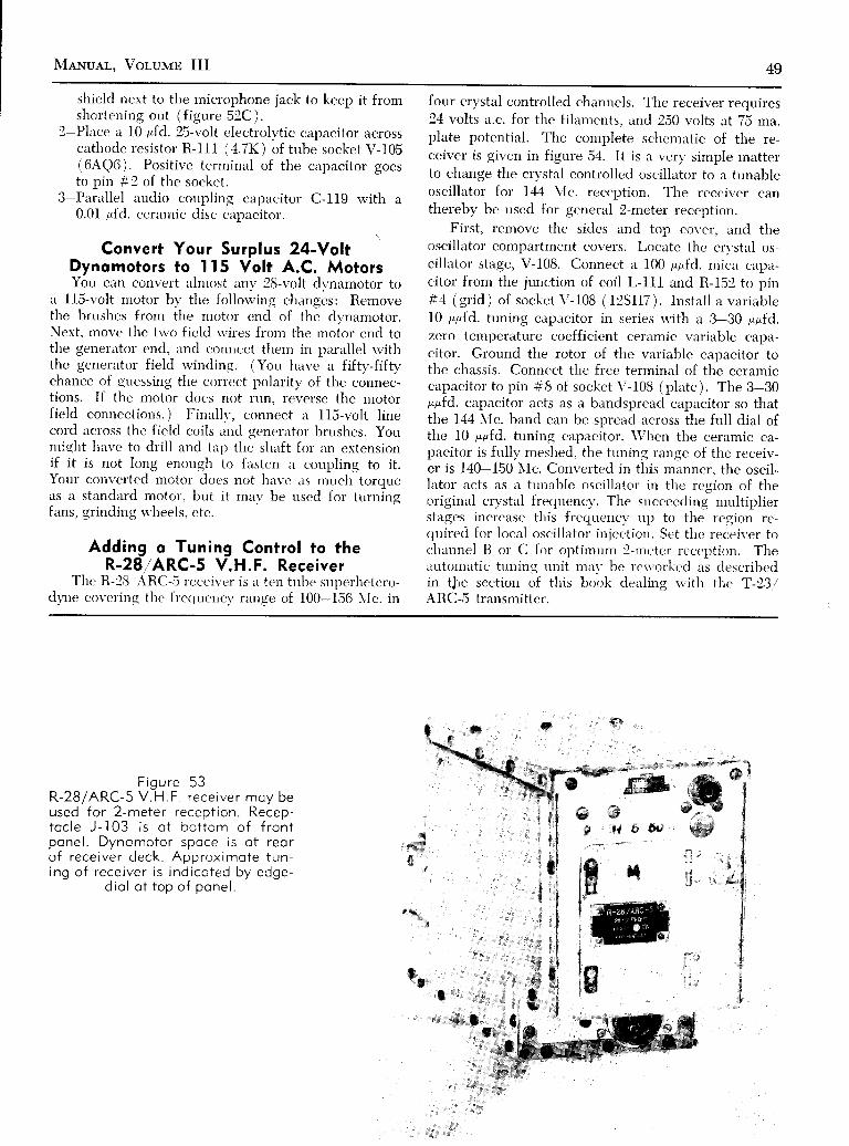
N{ewuer, Volurrn III 49
shield next to the microphone jack to keep it fromshortening out (f igure 52C).
2-Plrrce a l0 r,fd. 25-volt electrolytic capacitor acrosscathode resistor R-l11 (4.7K) of tube socket V-105(6AQ6). Positive terminal of the capacitor goesto pin #2 of the socket.
3-Parallel audio coupling capacitor C-119 rvith a0.0I gfd. ceramic dísc capacitor.
Convert Your Surplus 24-YoltDynomotors to Il5 Volt A.C. MotorsYou cirn convet't lrlmost any' 2E-vcllt dtrnamotor to
a ll5-volt motor b1' the follou'ing changcs: Removethe bmshes from the motor end of the dvnamotor.Next, move the tlvo field u'irers fron-r tl-re ,r-roior. end tothe generirtor end, and connect tliem in parallel u'iththe generator field rvinding. (You htrvc ri fiftv-fifty'chancc of guessing the correct polarity of the connec-tions. if the motor docs not run, reverse the n-rotorfield connections. ) Finallv, connect a 1l5-volt l inecord across the fielcl coils and qeneriìtor brushes. Youmight have to dri l l and tirp thc slraft fol irn extensionif it is not long enough to firsten a cor,rpling to it.Your converted motor docs not have trs much toroueas a standard motor, but it mav be uscd for turningfans. g l ind ing s ' l reels . c t r , .
Adding o Tuning Contro l to theR-28/ARC-S V.H.F. Receiver
The R-28 ARC-5 rccciver is i i ten tube snperhetcro-dy'ne covering the frccluencv lanE{e of 100-156 \lc. in
four crystal controlled channcls. The receiver requires24 volts a.c. for the filaments, iud 250 volts at 75 rna.plate potential. The complete schemirtic of the re-ceiver is given in figure 54. It is iì verv simple matterto change the crvstal controlled oscillator to a tunableoscillirtor for L44 N'Ic. reception. The receiver canthereby be used for generiil 2-meter reception.
First, remove the sides and top cover, and theoscillator compii.rtment covers. Locirte the cn'stirl os-cillator stage, V-108. Connect a 100 ppfd. ntic,a captr-citor from the jturction of coil L-lI1 and R-152 to pin#4 (gr id) of socket V-108 ( f2SFI7) . Insta l l a var iablel0 ppfd. tuning capiicitor in series rvith ar 3-30 ppfd,zero temperature coefficient cernmic variable capa-citor. Ground the rotor of the variable capacitor tothe chassis. Connect the frec terminal of the ceramiccapacitor to pin #8 of socket V-108 (plate ). The 3-30p1,fd. capacitor acts as a bandspread capacitor so thatthe 144 \Ic. band ci.rn be spread :rcross the full dial ofthe 10 ppfd. tuning cirpacitor. \\1hen the ceramic ca-pacitor is full1, meslied, the tuning rlnge of the receiv-er is 140-150 trIc. Converted in this manner, the oscil-lator acts as a tunable oscil lator in the region of theoriginal crvstal frerluencl'. The succeeding multiplierstages increasc' this frequencv up to the legion rr'-ry,rire'd for local oscilliltor injection. Set the receiver tocìrannel I l or C for optimum !-rrctcr rcception, Theltntomutic tuning nnit miu' be rcu'orked rrs clescribedin the section of this book detiling u'ith the T-23/AIìC-5 transmitter.
F i g u r e 5 3R-28 /ARC-5 V .H F rece i ve r moy beused for 2-meter recept ion. Receo-toc le J - l 03 i s o t bo t t om o f f r on tpone l . Dynomoto r spoce i s o f r eo ro f r ece i ve r deck . App rox imo te t un -i ng o f r ece i ve r i s i nd i co ted by edge -
d io l o t t op o f pone l .
,r%
I" *
*t ,,,,,,,.:l*;!&.,*

ú.ttJ
UJULUú.LO
. *Ú, À d
o \: @
óqi*-ú.
Ul-
:LUIUL'1
a
ù?gIÉ
f6*3ìi
Èl
9
J^q,
10
î rc q
t lt lL__!
r? lt r
ill li ts lI IE t
IIL
r -
o0'G(Erf, ' |?f i tgat9
1 0 I l 9 6 o - O @ ' O69tU
' 6{ U
úll I lsl l 9t < -@Ob
_ _ _cs u_ _ lflu-
t,6 J=i, (
Jig@ 6ar ?,, l i lu9?l tP x96x't .--
- ;oootsg rg tu
J n f l O € " l a g J ) O t E ' ' l l l U
-cm'sc-óru
I T
4 t-9
III
I
lI
l lt l
I s tIIIIIl r! Eqi,ifiFiISEIII| ̂ fl r'
l!àd,
- lo ;
I ssili i a w tl ' Ll - lr ll lf l
liiritI
I us r-liiEil]l:fl 1|
- - l
l lt l
i tqsr II aSi t It ; < -
Lstit__
t- IttIl\.
. ,L
t (
HÀl\
T
tÈ
g
Tin!3i ' i
EI
igI ;É o. rht r .
I
!N r l
l =s)
r'0x
trrT]'J. ZoO
f>r t {
, n n 9 9 t 9 s o r l
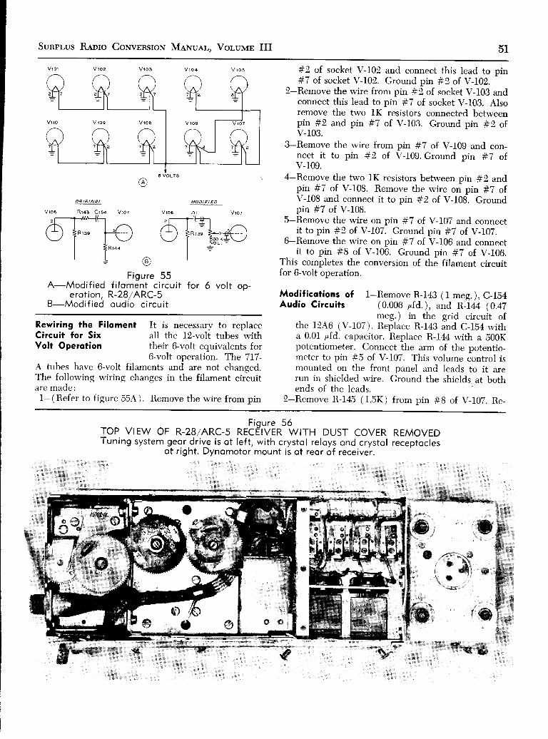
Sunpr,us R,qnro CoNvrnsroN MeNuer,. Voluur III 51
Fioure 55A-Modif ied f i lomànt circui t for ó vol t op-
erot ion. R-28/ARC-SB-Modif ied oudio circui t
#2 of socket V-102 and connect this lead to pin#7 of socket V-102. Ground pín #2 of V-102,
2-Remove the wire from pin #2 of socket V-103 andconnect this lead to pin #7 of socket V-103. Alsoremove the two lK resistors connected betweenpin #2 and pin #7 of V-103. Ground pin #2 ofv-t03.
3-Remove the wire from pin #7 of V-l0g and con-nect it to pin #2 oî V-109. Ground pin #7 ofv-109.
4-Remove the two lK resistors between pin #2 andpin #7 of V-108. Remove the wire on pin #7 ofV-108 and connect it to pin #2 of V-108. Groundpin #7 of V-108,
5-Remove the wire on pin #7 of Y-107 and connectit to pin #2 of Y-I07. Ground pin #7 of V-107.
6-Remove the rvire on pin #7 of V-100 and connectit to pin #8 of V-106. Ground pin #7 of V-106.
This completes the conversion of the filament circuitfor 6-volt operation.
Modificotions of l-Remove R-143 (1 meg.), C-lb4Audio Circuits (0.006 pfd.), and R-I44 (0.47
the 12A6 ( v-107 ) il:5i1""'ì-lX: :;'i ":iT;ll,,Ta 0.01 pfd. capacitor. Replace R-144 with a 500Kpotentiometer. Connect the arm of the potentio-meter to pin #5 of V-107. This volume control ismounted on the front panel and leads to it arerun in shielded wire. Ground the shields at bothends of the leads.
2-Remove R-145 (1.5K) from pin #8 of V-107. Re-
OR/€ I NA L
R 1 4 3 C r 5 4 V l o T v J o 6 . o l
MODI F/ ED
v 1 0 6
.r---îJG?,-r\( -
) |R ' . "\--./ |I
\9/
Rewiring the Filoment It is necessary to replaceCircuit lor Six all the l2-voli tubes rvithYolt Operotion their 6-volt equivalents for
6-volt operation. The 717-A tubes have 6-volt filaments and are not changed.The follou'ing rviring changes in the filament circuitiue maoe:
l-(Refer to figure 55A). Remove the wire from pin
K *
rop vrEw oF R-28/ARc-r *rEP'VE*tfu,r" DUSr covER REM.'EDTuning system geor.dr ive is ot lef t , with crystol reloys ond crystol receptocles
ot right. Dynomotor mount is ot reor of receiver.
$xltIf ,
' *1sr. 1!'
s
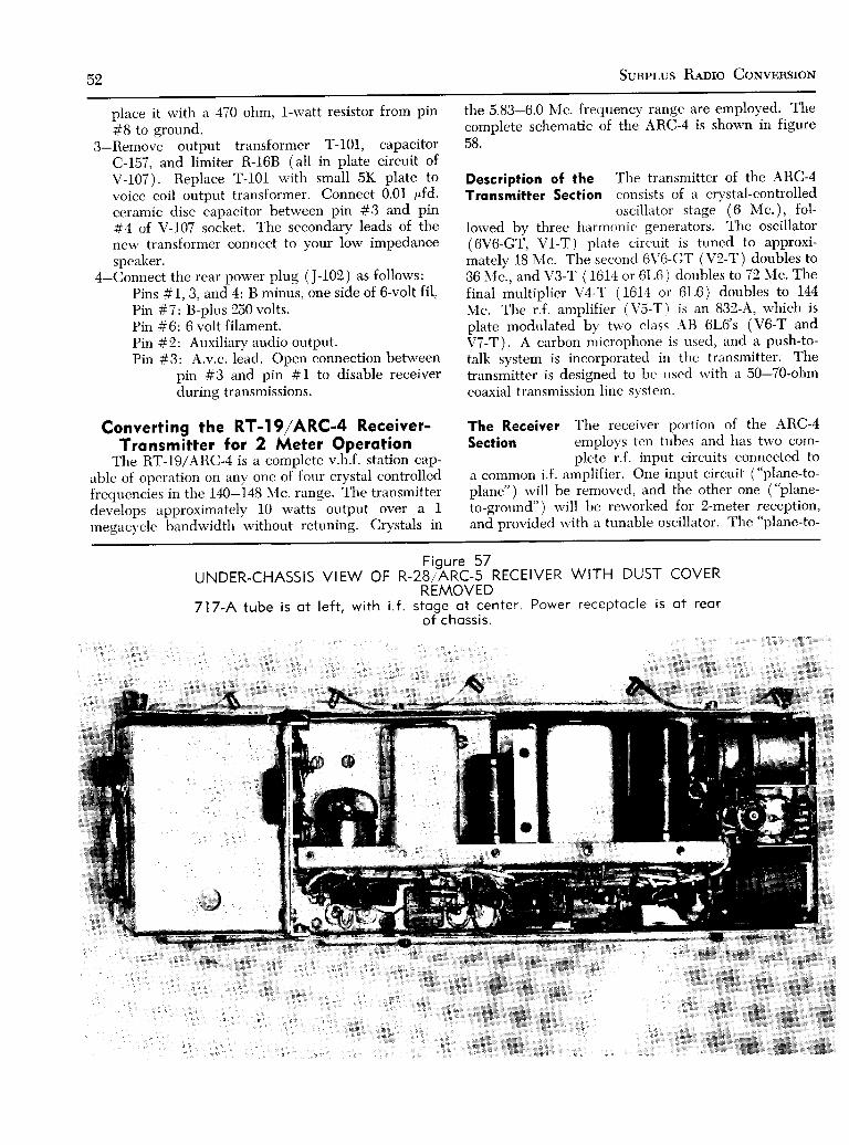
52 Sunpr-us Rerro CoNvnnsroN
place it with ir 470 ohm, l-watt resistor from pin
#8 to ground.3-Remove output transformer T-101, capacitor
C-f57, and limiter R-168 (all in plate circuit ofV-I07). Replace T-I01 rvith small 5K plate tovoice coil output transformer. Connect 0.01 r'fd.ceramic disc capacitor between pin #3 and pin
#4 oî Y-I07 socket, The secondary leads of thenew transformer connect to your low impedancespeaker.
4-Connect the rear power plug (J-102 ) as follows:Pins #1, 3, and 4: B minus, one side of 6-volt f i \Pin #7: B-pltrs 250 volts.Pin #6: 6 volt f i lament.Pin #2: Auxiliary audio outPut.Pin #3: A.v.c. lead. Open connection between
pin #3 and pin #1 to disable receiverduring transmissions.
Converting the RT-l9/ARC'4 Receiver-Tronsmitter for 2 Meter Operotion
The RT-19/ARC-4 is a complete v.h.f. station cap-able of operation on anv one of four crystal controlledfretluencies in the 140-148 N'{c. range. The transmitterdevelops approximntely 10 watts output over a Irnegac,vcle bandrvidth rvithout retuning. Crystals in
the 5.83-6.0 NIc. frecluency range are employed. Thecomplete schematic of the ARC-4 is shown in figureDó.
Description of the 'fl"re transmitter of the ARC-4
Tronsmitter Section consists of a crystal-controlledoscil lator stage (6 Mc.), fol-
lowed by three harmonic generators. The oscillator(6V6-GT, Vl-T) plrrte circuit is tuned to approxi-mately 18 Mc. The second 6\'6-GT (V2-T ) doubles to36 \ 'Ic., and VS-T (1614 or 6L6 ) doubles to 72 NIc. Thefinal multiplier V4-T (1614 or 6L6) doubles to 144lVIc. The r.f. amplifier (\'5-T) is an 832-A, which isplate modulated by trvo class -\B 6L6's (V6-T andV7-T). A carbon microphone is used, and a push-to-talk system is incorporated in the triinsmitter. Thetransmitter is designed to be used rvith a 50-70-ohmcoaxial transmission line system.
The Receiver The receiver portion of the ARC-4Section employs ten tubes and has two com-
plete r.f. input circuits connected toa common i.f . amplificr. One input circuit ("plane-to-plane" ) rvill be removed, and the other one ("plane-to-ground" ) rvill be rervorked for 2-meter reception,and provided u'ith a tunable oscillator. The "plane-to-
Figure 57UNDER-CHASS1S VtEW Or a-zeZARC-s RECEIVER WITH DUST COVER
REMOVED717-A tube is ot le f t , wi th i . f . s toge ot center . Power receptocle is ot reor
of chossis .
Menuel, Voluur III 53
ground" section employs a 6AC7 (V3-R ) mi.xer, cou-pled to three stages of 10 Nlc. i.f. amplif ication (V4-5-6-R) having a passband of about 80 kc. A i2SQ7(V7-R) is used as i in audio squelch tube, and a secondl2SQ7 (V8-R) serves as the second detector and audiostage. Trvo audio output strìges employing 12A.6 tubes(Vg-R and V10-R) are provided. The output of Vg-Rmay be taken from pins 22 trnd 23 of the plug terminalson the rear of t l ie unit (500 ohm circuit), and the out-put of V10-R appe.us trt panel jack J1-R and pins #24and 25 of the same plug.
A 6N7 double triode (VI-R) serves as a conver-sion crvstal oscillator and frequency quadrupler. Asecond 6N7 (V2-R) acts as a tandem doubler to thev.h.f. conversion frequency.
Power Supply ond The ARC-4 is powered fromControl System either 12- or 24-volts d.c., and
employs either a DY-9/ARC-Idynamotor ( 24 volts ) , or a DY-10 / LRC-1 (I2/ 24 volt)dynarnotor. Neither dvnamotor is recpired for the fol-lowing conversion. The ARC-4 is designed to be re-motely controlled from tlie C-51-/ARC-4 control boxrdrich has a chiinnel selector and audio input and out-put circuits. The control box is not rcrluired for theconversion,
Tronsmitter Cry'stals of the surplus FT-243 type areConversion used in this conversion. The two-meter
band rerluires crystals in the range of6.0 \{c. to 6.16 \Ic, For the Novice band, crystalsranging from 6.045 \lc. to 6.125 Nfc. should be em-ployed. To make tht:se cn'stals operate properly, twocapacitors in the oscilìator circuit must be chanqed.Remove C2-T (50 ppfd.) (betu'een pin #5 and pin#8) on socket \/ l-T ancl replicc u'ith a 15 irpfd. micarcapacitor. Next, re'rlove caltircitor C3-T (400 ppfd.)across oscil l irtor coíl L1-T ancl rcpìace u'ith a 100 ppfd.mica capacitor.
Microphone Voltoge -'\t thc rcrrr of the chassis onfor Tronsmitter thc transntitter sidc itre tr,vo
resis tors: l ì3-C (30 ohms,marked 230 \\ '-L), and R31-T (100 ohrrs, mirrkcd2200). Rcntove Iì3-C from thc clrassis ancl disconnectthe rvhitc n,irc rvith red-vellou' trirc,t'r' crrnnectccl to thc-�junctior-r of thc tu'o resistors. Crouncl thc ericl of R32-Tthat n'as connected to this s' irc'. Tc,nninals #1g ancl7 on thc rear chiissis plug i ire connec,ted toqethcr tocomplcte the c'ircrrit of R26-T ancl R3l-T. This pìacesR32-T irr st 'r ies u'ith R26-T, u'hich is thc urodulatorcathodc. bias rcsistor. Next, thc leird of lì19-T is dis-c'onnectecl fronr thc fi l irment circuit and attachccl tothe tcrnrinal of R32-T (fiatrre 60A ). Both tenninirls ofR29-T arc lx'piLsscd to gruuncl u'ith 50 pfd., 50 voltelectrolvtic filter capacitors.
Receiver Audio A portion of the audio signal volt-Modificotions age from the microphone is fed to
the receiver audio section for theintercom circuit. Disconnect the bare rvire lead fromthe grid (pin #5) of 6L6 tube socket V7-T that runsto the termin:rl board adjncent to the tube, and con-nects to resistor R28-T ( 250K ). Novv disconnect thervhite rvire rvith green tracer on the grid (pin #b) of12A6 tube socket Vl0-R. Disconnect the ,"vhite rvirervith red-brown tracer that connects to the junction ofR47-lR and R47-2R (10,000 ohms), which is mountedon the receiver side of the chassis. Now, connect arvire from this center tap junction to the end of R42-R(1500 ohms ) located cn the side trt the rear of thecha"ssis. The correct terminal is the one nearest thercru. This removes the B-plus from the receiver audiostirges when trirnsrnitt ing.
Reloy Circuit A Sarkes-Tarzian If-500 sil icon recti-Modificotions fic-.r is used in the circuit of f isure
608 to rectifv the filament voliagefor operation of relay S5-C. Íhe rectifier and filtércapacitor rrrc rnounted neirr the crvstal sockets. Thetu'o leads (rvhite rvith blue-green tracer) that werefonnerll. connected to R3-C (30 olims ) are attachedto the positive terminal of the rectifier. The negativeterminirl of the rectifier is attached to the 12.6-volt fila-rrent line through a 100 olim resistor. A b00 pfd., 2Evoit electrolvtic capacitor is placed betrveen the posi-tive terminal of the rectifier and ground as shorvn inthe schematic drarving. Finally. i"*o,re the crystalsrvitching relays.
Filoment Circuit To operate the fi laments from theModificotions po\\'er supply, strap the following
terminals on the rear power re-ccptircle plug in !{roups, irs follows: Group 1: l and 2.Cr<rr rp 2:5,6, 15 and 16. Group 3: J ,
and 19. Group4: 28 and 18. Croup 5: 8 trnd A1. Connect a 30K, 1-u.'irtt resistor from pin #18 to A2. Fiìament voltage isnppìie.d to pins AI and A2 (ground), as shorvn in thepo\\,er supply schematic ( f igure 65 ).
Receiver Remove tlie "plane-to-pliine" chan-
Modificqtions nel tuning unit located in the centerof the chassis by unscreu,ing the four
10-32 machinc scre\\'s beneath the ch:rssis. Removetht' top cover plate of the first i.f. transformer FLI-Rancl loosen tìre screrv inside that holds the coaxial l ineentc'ring tlie top of the trirnsformer. Pull up on theturring unit rrnd it u'ill corne free. Takc the sides offt lrrr trrning unit ald remove thc 6N7 oscil lator nlatec,oil L5-lì. This coil rniu' bc identified bv the greatnurnber of trrrns on it. -A.lso ren'ìoi'e one of the 50 lrpfd.ccrrimic ciipacitors in the unit. It u' i l l be needecl later,i i ìong u'ith tìre coiì. Finallr ' , rcmovc the platc l iolclingtlie iurxiliarv cirpacitors of tlic' tuning unit from thebrrck of t lre ARC-4 panel.

54 Sunprus Reoro CoNvnRSroN
TN]fl
ooìoèÉo
-,0)3É
atg
oI
FoL
Gtìoo
3R
[.,"
. R
ì R . n
II
r2FF I R
Figure 58SCHEMATIC, RT- 191 ARC-4

MehruAL, Vor.uvrn III IJIJ
DD
,f ar.rGf f --
J Y fan (a t .
{crÉi3 f.ra^ g r l v t l r t t t
l - -P l ' r+ - lt t l
ÉfFìI I T
,ro.l--E--r,*c'rcoi'rroffi---]
-i4t_---< |r ! oro c5, :
, - 1 ì-[- talrcror t
F igu re 58ScHEMAT|C, RT- t9 /ARC-4

F igu re 59PANEL LAYOUTOF CONVERTED
ARC-4 , SHOWINGPLACEMENT OF
MAJOR CONTROLSO - l d . c . m i l l i o m m e -t e r o n d s e l e c t o rsw i t ch o re o t l e f t o ft u n i ng d i o l . TypeF T - 2 4 3 c r y s t o lmoun ts i n ho lde r be -n e c t h d i c l P i l o tl o mp , o , c . sw i t cho n d i . f . g o i n c o n t r o l
o re obove d io l .
Coil L5-Iì is nnu' nrountccl on tl ie AlìC-4 chassis.aborrt 6li" beìrincì the' front panerl, and positione'cl asshosrr in {iqrrre ti l . Tìrc botton-r encl of the u'inclinq isgroundccl, irncl rr t0 1,pfd. ccrirrnic capircitor is cclnnect-ed across the ri ' irrding. Conncct the coil to .r 50 gpfd.cerirmic cirpacitor rr'hicli goos to tlic bottom end tenr-ri-nrrl on tìre ncrrrbv phcnolic strip irs shou'n in figure62. This coil converts the oscil l irtor from cn'stir l cxrntrolto ir tuned-plrrte ttrned-glid circrrit (f icrrre 60 C).
. \ c l t , . r runr ' t ' l ro l t ' i s nor i c l r i l l t c l t l r l r ,u { l t t l r c c l tass isn i , r r r t l r t ' s t ' c 'onr l l ro t to rn t t ' r ' n ' r in . t l o f t l r t ' p l r t ' t ro l i c s t r ip ,i rnd i i s rn i i l l c t ' r i rn r ic ' fe t 'd - th lL r i r rs r r l . t to l i s p laced in thec ' l rass is ho lc . T l i c t t : t l r i t r r t l o1 ' t1 , , ' n r . r r l . r to r i s con t te 'c tcc lt o p i n : 6 ( p l a t c ) o f t l r r ' 6 \ l ' , , r k r t \ - I - R . b e h i n c lt l re p l r t 'no l i c ' s t r ip .
A b o r r t t h i s s t a g e o t t l r , ' , J . r n r ( . . r r r t r i ' p a n e i p l i r t es l r o u l d b c c u t r ì n c l m o r u r t , ' r l i r , 1 r , , ' i t r o r r o l t t l r e f r o n t o ft l r e - L R C - - 1 . P o s i t i o n o f t l r , ' r r r . r i n r , , n t l o l s c r r n b e s e e n
@
5 - : r 'l a ! c o L
25 i>-^u \^ - - - ì | l - - l - l ìÙ \ - . : :e ! Ì ; . .- \ r
| ' , , R a , ) - a F
+ l , , a : r _ .
b J II
I
à)
F igu re ó0A-M ic rophone c i r cu i t o f ARC-4 . The m ic rophcne power i eod to R32 -T
moy be removed ond o t t oched to co thode p in =8 o f sccke t Vó -T torc i se modu lo t i on l eve l i f o l ow ou tpu t co rbon m ic rophone (T - ì7 t ype )i s emp loyed .
B-Rect i f ier system for re loy contro l .C -Rev i sed rece i ve r osc i l l o to r c i r cu i t . The l 0 sp fd . copoc i t o r i s t uned f rom
the f r on t pone l , os shown i n f i gu res ó3 ond 59 .
g +

Sunprus R luo CoNvnnsroN NleNuer,, Vorulrr III D I
V 5 - re 3 a a v 1 - î
6 V 6 G ÎA R / G / N A L C / R C U / T" N A / S € "
P i - R2 5 0 K
raov >--.ll--2 N D ' ' C a 6
RD E T E C T O R
2 N D
R2a R:
1 2 4 6A U D I OS T 4 6 E S
1 2 A 6A U D I OS T A C E 5
TC
îot 'II
8 +
E I''--l-
- t _- i '
- l _
a\,.:/@ { B
Fioure 62A-1 . f . go in con t ro l ( l obe led "no i seT ' )
f o r ARC-4B-Smo l l neon tube mokes i nexpens i ve modu lo t i on i nd i co to r .
i s moun ted i n rubbe r g rommet i n pcne l . Copoc i t once toshe l l pe rm i t s bu lb t o l i gh t ( see do f ted l i ne ) .
C -Mod i f i ed vo lume con t ro l c i r cu i t f o r ARC-4D-Cocx io l l eod fo r t r onsm i t t e r c r ys to l socke t ( see f i gu re ó l ) .
@
Neon l ompground o f
C O A X A LL E A D
r F R l - r
N E W C R T S T A Ls o c k € r M c u N T E o =A N P A N E L
M A D / F I € O C / R C U / T
a4.!.'=;-
Fiqure ó IUNDER-CHASSIS VIEW OF
-ARC-4 SHOWING CASCODE R.F
A M P L I F I E R ( R I G H T ) A N D M O D I F I E D R E C E I V E R O S C I L L A T O RCoox io l leod to pone l c rys to l ho lder posses o long center o f choss is . S i l i con
power supply for chonge-over reloy is ot lef t .
{#
w' *
fl*'*#.o.{F*Fb , "
*" lg i lGF, | * ^éffi::fì *%$i*t*,

58 Sunpr.us Renro CouvnnsroN
.ool
N O Î E :NEMOV€ CAPACITORSC1i-P ANo C1z-R tNCOUPLIN6 NETgORK
L 9 . 1 - R C 4 6 - R
L r - L s = s l T U R N s r z o E , o NS L U G I U N E D F O R M I
; f , " o ra . , j " ro re
L 2 - L 4 = l 2 î U R N S * 2 2 E .
$ 'o r r . , f ' r o rq
6 B 0 7 A- 4 3 3 9
llr
5 U 4 - G B
6T-.lF*f,geE #,.-^l _ f - 1? = : ' l f - + P l N * ! s
P r N * a 1 ( l ? v , )
P r N * A z ( c N D )r ' 6 a Q 7 Awts='oFlHr'
I .oolîo 6 .3 v , (F /6 .65)
Figure 64CIRCUIT OF CASCODE R.F. AMPLIFIER
FOR ARC-4Grid-dip coi ls L- l ond L-2 to center of 144Mc. bond. Shield is ploced ocross center ofóBQ7-A socket to reduce coupling betweenthe co i l s (see f igure ó l ) . L ink co i l s o re twoturns of hookup wire.
in figure 59. A soft aluminum plate is placed over theopening left by the removal of the auxiliary tuningtrnit, and a Nation:rl type ìvICN dial is mounted on thepanel. The shaft of tlie dial is about 4" from the topedge of the panel, and about 41A" from the left edgeof the panel. The dial drives a small l0 ppfd. "APC-
type" vruitrble air capacitor that is mounted on analtrmintrm bracket placed abort 41i" behind the frontprrnel (figure 63 ). The capacitor, therefore, is im-medirrtelv adiacent to the ceramic feed-thru insulator
ì15v tu
F igure ó5POWER SUPPLY FOR ARC-4
Tronsformer is roted ot 325-0-325 volts ot255 mo., C.C.S., 5 vol ts ot 3 omperes, ond12.ó vol ts, center-top ot 5.3 omperes. Pi lotlomp bolonces current droin of óBQ-74 cos-
code tube.
rnounted on the chassis deck. The capacitor is drivenby the dial through a phenolic rod and a shaft coupler.The rotor of the cnpacitor is grounded, and the statoris attrrched to the terminal of the feed-tluu insulator.The modified oscilltrtor circuit is shown in fieure 60C.
Ponel Controls Vrrrious other controls are placedon the front panel, as seen in figure
59. Across the top are (left to riglit) a 0-l d.c. millia-meter used as a tuning meter, an i.f. gain control(250K, see figure 62A), the a.c. po\\/er srvitch, and theantenna lotrding capacitor, CfO-T. Belorv this, at the
a4ù
F i o u r e ó 3TOP VIE:W OF ARC-4S H O W I N G T U N I N G
CAPACITORThe opening lef t by re-movo l o f oux i l io ry tun ingun i t i s covered w i th o lum-inum plote. "APC-type"
t u n i n g c o p o c i t o r i smounted to brocket otopthe olote. ond connectedto osc i I lotor c i rcu i t v ioceromic feed-thru bush-ing . Osc i l lo to r co i l i s o treor of copocitor, withslug project ing through
chossis.
&e-

MaNuar-. Vor,urras III 59left is tlie meter selector srvitch, receiver tuning con-trol, and modulation indicator (figure O9B ). Thetransrnitter amplifier tuning control is at the far right.Receiver adjustment controls, transmitter crystalsocket, transmit switch, and phones and micropúonejack are placed at the bottom panel edge.
The 500K volume control has one terminal ground-ed. Remove the wire connecting the grid of IZAOsocket V59-R to resistor R40-R ( 100K ) which is thesecond resistor from the end of the terminal boardlocated near the four relays beneath the chassis. Con-nect a wire from the grid of tube VS9-R to the centerarm of the volume control (use shielded rvire). Con-nect a rvire from the remaining terminal of the volumecontrol to resistor R40-R at the terminal where thewire was previously removed (use shielded wire ).Remove resistor R40-R by clipping the leads.
A short length of RG-59/U coaxial cable is usedto connect the crystal socket to the oscillator tubd, asshown in figure 62D. The shield is grounded to thechassis at both ends of the conductor.
A Coscode Amplif ier The sensitiviw of the ARC-4for the Receiver receiver leavés much to be
desired if stations beyondthe line of siglit are to be worked. A simple 6Be7-Acascode amplifier may be built into the rèceiver sec-tion that rvill greatly enhance the performance. Theplacernent of the amplifier can be seen in figure 61. Asmall copper shield plrrte is mounted àcross the6BQ7-A socket, and is grounded to pins #4 and gand the center stud of the socket. The neutralizingcoil L-3 passes through rr ll-inch hole drilled in thé
shield. Coils L-I and L-2 irre mounted on either sideof the shield plate. The cascode schematic is shownin figure 64.
The Power Supply The power supply is placed inthe rear chassis area, as shown
in figure 66. The wiring of the supply is shown infigure 65. To balance the filament drain, the 6Be7-Aand the pilot lrrmp 2.e rvired as shorvn in the ùhe-matic, All other filaments ar.e rvired correctly whenthe rear- po-wer connector terminals are strapped aspreviously described. It is necessary to insert a 780_ohm, 20-watt resistor in series rvith the receiaer B-phrs terminals of relay S5-C to hold the receivervoltage to 300.
Alignment of the The first step is to align the re_ARC-4 ceiver oscillaìor. The s-Íue of the
justed to res onate .h""::i:tl,?i"%'#"i:.( H;l I H5:dip oscil lator). The plate coil slug (Lt-R) shoulà beadjusted so the receiver tuning óapacitoi tunes therange 8.5 NIc. to 8.8 NIc. Set the oscillator to approxi_mately 8.65 N,Ic. and tune the harmonic generator cir_cuits for maximum meter reading as sho-wn in figure6]. The slugs in these circuits are set very closé tothe-correct adjustment when you receive tÉe ARC-4,so do not alter the setting too much! lVith an antennaon the receiver, you should norv start to hear two_rneter signals. Adjust the three r.f. trimmers (lowerleft corner of the panel ) from left to right for maxi_mum signal strength. One adjustment rvill hold over atuning range of about one megacycle. Finally adjust
F iou re ó6POWER- SUPPLY IS
INSTALLED INDYNAMOTOR AREA
OF ARC-4Tronsformer is ot left,with f i l ter copoci tor tor ight of tube. ' Extro 20pfd. , 450 vol t coooci tor isodded to output of supplyto reduce hum. Smo l lo luminum box is p locedover reor of rect i f ier tubesocket to prevent dongerof shock f rom terminols.

60 Sunpr.us Rarro CoNvnnsroN
R E C E I V E R ' I ' U N
I N G C H A R T
M E T E R P O S I I I O N Î U N I N G A D J U S f M E N I
I T U N E F O R N A X . R € A O I N G )M E T E R R E A O I N C ( O - 1 M A
o s c . G R / o L ' - R 0 . 2 - 0 . 6
2 N D U U L T . G R / D o , 1 - o . t
R O M U L T , 6 R / O o . o a - o
v . c L 4 - RU€ASUR€ WITH VTVUo N a . v . c . a u s s
t R A N S M t î î E R T U N T N G c H A R î
M E T E R P O S I Î I O NT U N I N C A O J U S T M E N T
( TUNE FOR UAX, REAOING )M E T E R R E A D T N G ( o - i M l
o s c . e R t D
I S T B U L T . 6 R / D L 1 - î - L 2 - T
2 N O M U L T , 6 R / D L 3 - f - L 4 o . 3 - 0 . 5
3 R D M U L f , G R / D
R , F . A M P . G R I D L 6 o . 2 5
P . F , A H P . G R I O L A o . 2 5
R . F . A U P . P L A T E L 9 - rI M / N . R E A D I N G )
o . 5
Figure 67METER CHART FOR TUNING RT- I9 /ARC-4
the slugs of cascode coils L-l and L-2 for best signalreception.
The crystal is norv plugged in the transmitter andthe multiplier circuits are tuned for mtrximum metercurrent, as indicated in figure 67. Load the antennaby increasing the loading capacitor (C10-T) and thentune tlie r.f. amplifier stage for minimum dip. Repeatr-rntil maximum loadine is obtained uùile still observ-ing ir pìirte crrrrent t l ip.
Modern, TVI-Proof Conversion of theSCR-522 Tronsmitter
Many conversions have been shown for the BC-624transmitter portion of the SCR-522 v.h.f. receiver-hansmitter. The conversion described in this sectionis recommended for trvo and six meters, as it elimi-nates the t.v.i. difficulties normally encountered withthis equipment. The unconverted trtrnsmitter is shownin figure 68.
First of all, remove the triinsnritter from the cabinetand strip off unnecessary componcnts, such as thetuning slides, etc. Nfove the pou'er connector to therear of the chassis as shorvn in figurer 69A. Nlake up apower cable as shown in figure 698, using #14 wirefor the filament leads, as sho*'n. Next, mount aSO-239 coaxial connector near the tripler stage, asshown in figure 69C, and run a coitxiitl lead from theconnector to the antenna link of the trar.rsmitter.
If a carbon microphone is used, it is necessary toinstall four "pen-lite" batteries in series s'ith the pri-mary rvinding of the microphone transformer. Betterstill, a crystal microphone can be emploved u'ith thetransmitter if the simple transistorized speech amplifier shor.vn in fisure 70 is installed in the transmitter,It is recommendìd over vaclrum tube amplifiers sincethere is less danger of erudio feedback. A IN34 diodercctifies the filament voltage to deliver a small nega-tive potential suitable for the transistor. Remove themicrophonc trtrnsformer and connect the output of thetransistor arnplifier to the
"l-rot" terminal of volume
contro l #1t5.
Figure óBT H E
U N M O D I F I E DBC-624
TRANSMITTERSECTION OFTHE SCR-522
V . H . F .TRANSMITTER-
R E C E I V E R
.�' \' '{t- - _
t - a - - ;
,F
:c-1ft
w
1.
$"".n*iì! ,
@,xf"l;:
& , . i
1 qî.;ia
.Pt *9
i, En } i*-.s

Mexual, Voluur III 61
AENO TA8 OY€R AND. /80Lr ro S tDE
B I A S M O U N T / NL/ NE V/TH
B + ' 2 A 6 t S \"tf , l \
\ 9,/
USE 5
C O N N E C I O R D E f A I L - T O P V I E W
@
@
Figure 69{-pe1rys1 p lug modì f icot ion , for 522 t ronsmit ter , for use wi th o.c. supply
shown in f igure 75.B-Connect ing coble between t ronsmit ter ond power supply.C-New cooxio l ontenno receptocle is mounted in corner of t ronsmit ter
chossis neor 832-A t r ip ler s toge.
C A B L E D E T A I L - X M Î R T O A N T E N N A C O N N E C I O R O E I A I L
€,/a\@
HOUNT 50-239 0N t 3 /A . P tLLARS.W/RE WlTH COAX,UP TO ANTENNA
T.V.l.-Proofing the Install a 0.001 prfd. disc ceramicTronsmitter capacitor across the filament
pins of each tube socket. By-pass all leads on the pou'er connector with 0.001 pfd.disc ceramic capacitors. In addition, bypass eachmeter lead rvith 1.5 K\/, 0.001 pfd. disc ceramic capa-citors. Use a meter rvith a metal case, or else cut asection of a tin carn to cover the rear of the meter ifa pl.renolic-cased meter is used. Ground the can tothe transmitter panel, permitting the meter terminalsto pass through holes cut in the rear disc of the can.
To shield the transmitter completely, it may bemounted in the metal case from a BC-375 tuning unit.Small, }i-inch lioles should be drilled in the case to aidventilation. The completed transmitter, mounted ona relay rack panel is shou'n in figure 71.
Circuit Modificotions The brri id straps that con-nect the plate terminals of
the 832-4 tubes to tl ie tank circuits should be removedand replnced u'ith copper strap. The braid gers warmduring operation of the transmitter because of the
2 N l o 5C R Y S T A LM I K ECON N ECTOR
high r.f. resistance. Transmitter output increases whenthe braid leads are replaced. tr'Iodulation is also im-proved when the 1246 audio tubes are replaced with12V6-GT's. No rviring changes are necessary.
A crystal-v.f.o. selector srvitch that may be in-corporated in the transmitter oscillator circuit is shown, f .rn rrgure /1.
To operate the 522 transmitter on six meters, thefollorving coil changes are necessary: Replace thetripler (first 832-A) plate coil rvith a new inductanceconsisting of 14 turns of #\4 enamel u,ire, Íé" diameter,and abotrt Ilí" long. The B-plus lead is attached tothe center of the coil. The antenna coil consists of 5turrrs of #14 insulated wire rvound over the center ofthe plate coil. The tripler stage norv acts as a six-
Î o6 5 5 7G R I D
r o o ! F
VOL. CONTROL
- - z . z Ko o rD L 5 C4 L L R E S / S T O R S 0 . 5
Fiqure 70S I M P L E T R A N S I S T ' O R S P E E C H A M P L I F I E RPERMITS USE OF CRYSTAL MICROPHONE
WITH SCR-522 TRANSMITTERSmol l ompl i f ie r moy be mounted be tweenvolume control ond the microphone jock on
the ins ide o f the choss is .
Figure 7lMODIFIED 52i TRANSMITTER IS
MOUNTED ON RELAY RACK PANELCose f rom BC-375 tun íng un i t i s s l ipped overchoss is to comple te on t i -T .V . l . sh ieLd inq . Ad-di t ionol conversion informotion is qiven in Vol.I of the "Surplus Rodio Conversio-n Monuol."
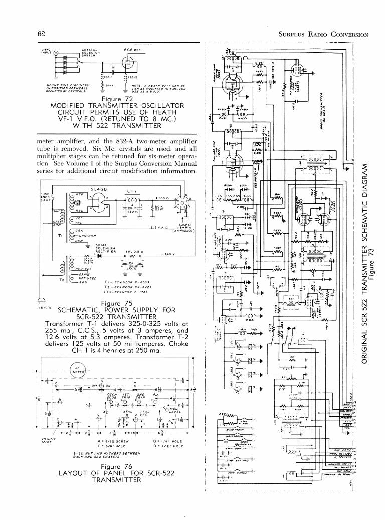
00l-.;
62
C R Y S Î A LS E L E C Î O RS W I T C H
6 G 6 o s c .
l z . E - z
N O T E : A H E A T H V F - I C A N 8 ECAN 8E MODIFIED 70 8 MC, FOR
M O U N T T H | S C I R C U I T R YI N P O S I T I O N F O R M E R L YOCCUPIED 8Y CRYSTALS. : : U S E A S A V . F , O .
Figure 72MODI F I ED TRANSMITTER OSCILLATOR
CIRCUIT PERMITS USE OF HEATHVF- I V .F .O . (RETUNED TO 8 MC. )
WITH 522 TRANSMITTER
meter amplifier, eìnd the 832-A tu'o-meter amplifiertube is removed. Six NIc. crystals are used, and allmrlltiplier stages citn be retuned for six-meter opera-tion. See Volume I of the Strrplus Conversion Nlanualseries for rìdditionrìl circuit modification information.
î =S O C K E T8 - P I N
Tueueuot)G R N
A R N
G R N - B R N
5 O M A .S E T E N I U MR E C Î I F I E R
* t ^
T r - s r A N c o R P - a J 3 9
T z - s r A N c o R P A - a 4 2 |
C H r - s r A N C o R c - t 7 o 3
Figu re 7 5
E A .?ou5 0 v
t._I
v sc H'S*1'frr'l$ild?+iiJ Fo RTronsformer T- I de I ivers 325-0 -325 vol ts ot2 5 5 f f i o . , C . C . S . , 5 v o l t s o f 3 o m p e r e s , o n d12.6 vol ts ot 5.3 omperes. Tronsformer T-2de l i ve rs 125 vo l t s o t 50 m i l l i omperes . Choke
C H - l i s 4 h e n r i e s o t 2 5 0 m o .
8 *
III
TO SU trM I K E A = a t 3 2 s c R E w
C = 3 l E " H o L E
8 / 3 2 N U T A N O W A S H E R S B E T W E E NR A C K A N D 5 2 2 C H A S S I S
Figure 76LAYOUT OF PANEL FOR SCR-522
TRANSMITTER
E A .20DF
4 5 0 V
_rI
r00 lLo . 5 w
R E D - Y E L
Sunpr,us Renro CoxvERSroN
lnt xq a
ì a\ a
!IIi t
\\\I3 tò hò qÈ s
a\str i:i
- . I'!'r i1 ! i
rr
tHI
l - J
Ia
ì:is'-
=ú,(9soUF
:LUTU(/',
#,-F t \F o )= 5ù . 9ZtJ-
ú.FNNLO
ùUv)
J
zo-d.
o
J
cì-aot 6.2ot
ffr. rl Ht,t - a e t z t e t , - t t l
h
if-l r
nIìo
I H
[ t .Ira
a
R]-lr,
1-{r'
l-tl-''
aItcl:elo
dtJyrtf*î
t - c '
ao/q f/ÌooH
doJdrnooàl,^.____^-)so -frdo
d H e o {2 / x / O 7 / d t
- -
- ( , IHozhOJ ,jJ H2
1 6
241 22r ,1zoJ ' ' '
4 ì
dtav turr os?
{Ffr ., - eo /
{ H t .O / - Z O t
. l t t 'Vu l t ' (U

MeNuer., Vor-unan III 63
I
Figure 74POWER SUPPLY
FOR SCR-522TRANSMITTERIS ASSEMBLED
ON AUXIL IARYCHASSES
See f igure 75 forschemotic
The BC-312 ond BC-342 Series ReceiversThe BC-312 and BC-342 series receivers are, with-
out modification, accept:rble communications receiv-ers. Hou'ever, their perfolmance can be greatly im-proved for amateur comrnunicrìtion rvork bv makingcertain modifications in vtrrious portions of the re-ceiver. Any one of the chirnges or iill the cl.rangesmay be made, each change adding rr certain amountto the performance .rncl flexibilitv of the receivers.The various changes u i l l be treated sepirrirtelv so thatany one or :rll the chanqes mtry be m:rde at the discre-tion of the ou'ner of tlie recciver.
Power Supply If the receiver is :r BC-312, afor the BC-3I2 po\\ 'el suppl,v must f irst be con-
.stnrc.tecl. Tlie BC-342 is ecluippedu'ith an integrtrl 1l5-r'olt po\\'er supply but the BC-312has a l2-volt dvnamotor in pl:rce of the iì.c. powersupply of the BC-3.12. Othenvise the receivers aresubstantially identical. it u'ill be irssumed throughoutthis and subsequent discussions that the owner oJ thereceiver has a copy of T\l If-850 or one of the otherinstruction books on this series of rcceiver since theseinstruction books u'ere fumished u.ith the ieceiversor \\'ere generallv rrvailable :rt tlie time the receiversrvere sold.
The Dvnnmotor must first be swrìng out on itshinges, and then the lerids from the dvnamotor to the9-terminal connection strilt removed. A porver supplysnch as shou'n in Figure 77 trnrJ diagrammed in Figure
79 must then be constructed. The one il lustrated em-plo1,s a Signnl Corps C-228 po\\'er transformer, rvhichis the same one rìs rvars used in the RA-20 power sup-ply for the BC-342. A l irrge number of these powertransfonners have been available, but if one crnnot beobtained, anv po\\,er transformer having a 650-volt to750-volt center-t:rpped high-voltrrge winding, a S-voltfilarnent rvinding for tlie 5Y3-GT, and one or trvo 6.3-volt filament windings at 1.75 amperes or gr.enter rvillbe strtisferctory, If the trilnsformer has tivo 6.3-voltf i l trment rvindings (such as the UTC tvpe R-ì2) thel'are connected in series to obtain the 12.6 volts neces-sary for heater operation of the receiver. If tlie trrrns-former has only, one 6.3-volt rvinding nn additionalver1, small 6.3-volt 2-ampcre fi lament tiansformer mustbe plrrced in the porver supplv and connected in serieslvith the 6.3-volt s'indinq on thc main pou.er trans-former to obttrin the 12.6 volts. The junctìon betu,eenthe trvo 6.3-volt filament rvindings should be groundedin tlie po\\/er supplv.
One con-rplicirtion is introduced bv the fnct thatthe dial-lamp circuit uses tu-o 6.3-volt lamps in seriesto ground, so that if the lead to the dial ltrmps is con-nected to either of the hot 6.3-volt f i lament leads thelamps u'i l l onlv receive half voltage. This may be sat-isfactorw, since the lamps give adecluate l iglit at thisvoltiìge, or the trvo lamps mnv be connected in parallelbv removíng tl ie bezeì thrrt covcrs tl ie tu'o lamps andrervirinq them.

64 Sunpr,us Reoro CoNvrnsrox
il e
FiEute 77.
FRONT VIEW OF THE CON-VERTED BC-3I2 RECEIVERWITH THE POWER SUPPLY
ALONGSIDE.The cooxiol i. l . eneryy output rit-t ing con be seen on the panel infhe position lormerly occupied bytàè power connector. Ihe swiúchmounted ot the bottom ol thevefticol row ol jocks is the noise-limìter on-oll svitch. fhe powersrtpply is notmally mounted rc-motely lrcm the .eceiYer and con-trclled hy the OFF-MVC-AVC switcrr.
The balnnce of the power s,rpply is quite conven-tionnl. The VR tube shorvn in Fisirre 79 need not beused unless desired, but its use dóes afford improvedoscillator stnbility.
Yoltoge Regulotion for The high-freqtrency oscil-H.F. Oscil lqtor l irtor used in the receiver
is qrrite stable, but rvhenoperirting on tl're 14-\'lc. bnnd there is some variationin the tonc of ir c.rv. signal *'hen thc r.f. gain is varied,or u'hen the l ine voltaqe viir ies i is ir result of a house-hold refrigerator turning on or off or from some sim-ilar cause. This condition is cured by using voltageregulation on tl're plnte supply voltage to the high-frequenclt oscillator. The incorportrtion of voltage reg-ulation on the oscillator requires thtrt a lead bebrought out of tl.re oscillator compiìrtment for separateplate-voltaqe feed to tlie tube. This operation requiresremovirl of thc cover from the oscillntor compartment,and the removirl of 30,000-ohrn resistor Ra1. This re-sistor is replrrced lry a 1000-ohm )l-rvntt carbon resistor.The r'.f. stiige chiissis is then lifted btrck, after re-moving the leads to thc' tube ciips, and the plate-voltnge terminal corning or,rt of the oscillator com-p:rrtment is bv-passed rvith tr 0.002-irfd. posterge-stampmicrr capircitol rvhich can be placed flitt against thechassis belorv the terminirl strip. The lead for platevolti igc to the oscil lator is then brought under the r.f.chtrssis ancl dou,n throush the hole rvhere the otherleads feeding the r.f. chassis pass. This plate-voltageIead then goes, of course. to the plate of the VR-105.
R.F. Chonges Thc r.f. svstem in the st:rndard re-ceiver is slightlv lacking in gnin and
signal-to-noise ratio on the highest frequency range.Tliis condition ciìn be checked tr1' removing the an-tennrr leacl from the receivcr, turning the receiver rvidoopen on \{VC, and then rotating the trirnmer APC on
the first r.f. stage through resonance. Only a veryslight increase in noise level will be noticed rvhen thistrimmer passes through resonance.
The most satisfactory rvay of correcting this condi-tion (and this method was proven best after tryinga number of other expedients ) is to replace the 6K7first r.f. stage rvith a 6SH7. It so happens that the re-cciver is laid out in sucìr ti miulner that a single-endedtube in the first r.f. stage gives much mole directleads than the doublc-c-nclcd tube originally used. Thoprocedule is irs foìlou's:
Remol'c thc trrbes from the r.f. chassis and invertthe chassis as firr irs possible. Remove the leads frompins 3, 4, 5, 6. irnd 8 of the tube socket for the first r.f.stase. Rclr.rovc tl ie old cathode-bias resistor RS-164.Run a 100-ohm l-u'att resistor from the small micartaterminal bloc'k for the \{VC lead to pin 5, and also runto pin 5 rr lcacl from the cathode b1'-pass section of thecirpacitor block for the st:rge. Install an additional0.002-pfd. postage-stamp mica capircitor as a cathode-br'-pass from termintrl 3 to terminrrl 1. Separate thescrccn-volti,rge lead tl.rat u,ent to terminal 4, shorten ituntil it fits more netrtly ancl sokler to pin 6. Norv runthe plate lead for the tube. u'hic'li dicl go to terminal 3irnd rnn it uncler nll thc l'ire's neirr tl're heater end ofthe socket and conncct tliis ìc'rrcl to terminal 8. Removethe lead rvhich u'ent to the qricl cap of the 6K7, scldera rvire abor"rt 1)í inches lonq to this terminal on themain chassis, push tl ic sub-chrrssis dorvn as far as itcan go and stilì reuch terurir.ral -l on the tube socketrvith a soldering iron. ancl solder this new lead toterminal 4. Thcn pusìr the chassis back into placegentl1,, at thr: srinrc tir.ne miiking sure that the gridlead to the tube ( ternrinal '1 ) keeps free of the chassisand bencls out tou'rrrcl the gringed tuning capacitor.
It r i ' i l l nos' ìre neccssruv to re-align tl ie r.f, stagesof thc receiver slightly (nof the h.f. oscil lator how-

Marruer.. Voluun III 65
Figure 78.
UNDERCHASSIS VIEW OF THERECEIVER AND POWER
SUPPLY.The bent-aluminum chossis holdingthe 746 noìse limìter tube can beseea óehind the power-cable recep-locle. fhe odded chossis is mounted
to the lrcnt panet.
ever). Peak up the 6L7 mixer stage first, then thesecond r.f. stage, and then the first r.f. stage. The gainwill be found to be much greater than before, and theincrease in noise when the first r.f. stase is trimmedthrough resonance will be found to te 'u"ry pro-nounced, If a tendency torvard instability is encoun-tered near maximum gain on N{VC, re-trim the mixerstage padders slightly until the instability disappears.
All these receivers have a certain amount of back-lash in the vernier tunine control. In several receiversthe amount of backlash has been reduced to a vervsmall amount by carefullv lubricating all the gearswith a small amount of vaseline, using a toothpick ora matchstick to applv the lubrica.nt. Then the back-lash, which in the receivers mentioned was caused byaxial motion of the tuning-crìp:ìcitor garìg, can be sub-stantially eliminated bv careful adjustment of the ballthrust bearing at the oscillator end of the tuning gang.This bearing is inside the oscillator compartment.
l.F. Amplif ier The i.f. amplif ier operates quite sat-Chonges isfactori lr ' . but the action of the crys-
tal filter leaves much to be desired.The reduction in set gain u'hen the cryrstal filter issrvitched into operation can be greatlv reduced by thefolloiving procedure: Remove the cover from the crys-tal-filter transformer. Scrape the stud rvhich serves asa stop for the rotation of the cr1'stal-phasing capacitorand solder a very small wire to this stud and to thesmall srvitch contact on the other side of the phasingcapacitor. Then turn the phasing control rrntil themoving contact rests firmly against the stud. Re-installthe cover of the transformer and align the slug rvhichcomes out of the toTt of the crystal-filter tranìformerfor maximum noise with the antenna removed fromthe receiver. This position of the control ( 180" from
the old position) now serves as the crystal-out posi-tion, and the reduction in gain rvhen the crystal filteris switched into the circuit rvill be very small.
A further change in the i.f. amplifier rvas made inthe receiver shorvn in Figure 77 to bring out i.f. energyfor the operation of external devices such as a panor-amic adapter, a narrow-band F.NI. adapter, or anotherexternal unit such as a single-sideband channel. Thechange consisted in merelv rvrapping 7 turns of hook-up wire around the form between the two i.f. coils in-side the last transformer, connecting one side of thiscoil to ground and the other side to the center con-ductor of a piece of RG-58/U cable. The cable isbrought into the transformer by first removing theblack wire going into the transformer and groundingthe capacitor to :r soldering lug trnder the screw adja-cent to the terminal from u'hich the black rvire tvasremoved. It mny be necessuy to ream the hole fromwhich the black rvire rvas removed sliehtlv in orderto be able to insert the insulation and Ih" irrrr", "orr-ductor of the coaxial cable. The outer conductor ofthe coaxial cable is grounded outside the transformer.The coupling connéctor for the coaxial cable wasmounted on the front panel of the receiver in theposition formerly occupied bv the power-cable con,nector, which had previously been removed.
With the i.f. energy obtained from the panel co-axial connector coupled to an external coil resonatedto the intermediate frequencv by means of a small 7-turn coupling coil, approximately 10 volts peak wasmeasured with a normal signal input and the receiveroperating on a.v.c. With the receiver on MVC, morethan 50 volts peak could be obtained. This voltage isof course quite trdequtrte to operate any of the acces-sories mentioned in the previous paragraph.

66 Sunprus Relro CoNvrnsrox
r t l l t t l
P O W E R Î R A N S F O R M E R C O L O R C O D E :F O R C . 2 2 I I Y P E
REO : I IO VOL ÎS COMMON. BLACI ( : I 20 VOLTSGR€EN = . IO5 VOL IS
BROWN: t 2 VOL ÌS , NO C .T .aLUE : l Z VOUTS, SLA IS WITH TRACER = C . r . /
B L A C K : H . V , , Y E L L O W : C . T .
Figure 79.SCHEMATIC DIAGRAM OF THE POWER SUPPLY UNIT.The color code shown of the bottom of the drowing is lor t f ieC-228 power transÍormer which may be avai loble. I l this trons-Íormer is not ovai lsble o conventionol power tronslormer hovingtwo 6.3-volt windings moy be used os described in the texl,
Cr , C : - l 6 -p fd . 450-vo l t e lec t . CH-15 henrys 100 mo.T-700 v . c . t . 100 mo. ; 5 v . 3 R1- l 2 ,500 óhms l0 l vq f ts
o . ; ó .3 v . 3 o . , ó .3 v . 3 o . Rr - l 00 ,000 ohms 2 wot tsin ser ies w i th center S-S.p .s . t . o .c . t ine swi tchgrounded, Ot 12 ,6 v . c . t . F -3-ompere fuse
Audio System Tlic audio s)'stcm of t l ie 312 and 342Chonges rcceivers le,tives muclì to be desired.
There is inaclequrìte gaìin for recep-tion of weitk signals on crystrìl filter, the frequency re-sponse is cluite poor (though intentionallv so for mili-tary use ), and the hurmonic distortion is severe. Allthese undesirable coì'ìditions wcìre overcome bv therelativcìv simple c'hirrrgc in tlrc, auclio systern shownin Figtrre 80. A 688 diode-pentode wiìs used to re-placc the 6R7 dioclc-tl iode previously used, rìnd the6F6 u'as replacecl u'itlr a 6V6. Shturt feedback from theplate of the 6V6 to 1l1c plate of the pentode section ofthe 688 \\'as used to improve the frecluency responseand rcduce l)armonic distortion. Also, the feedb:rckrìlmost completely eliminatcs the l ium in the audiosvstem of these reccivcrs. TIte cathode resistors for tlietu'o stages \\'ere left the samc, but an itclditionrìl 25-pfd. 25-r'olt electrolytic wrìs plrìced across tlie cathodelesistor of thc 688 so thitt the [arin corìtrol wouldcompletclv cut off the iurdio output s'hen ttrrned cleiu'dou,n in tl ie it.v.c. position.
Tìre audio transforn-ìc.r' tlrat u.as usc(l in thc platecircuit of the 6Iì7 is r('rnoved frorn the circrrit btrt n'asleft in placc: sir-rce the spacc wits not rc.(lrlired and itapperìr('cl to be difficult to remove. \\/he-n iì noisesilence.r, to be describcd later. is to be usecl in receiv-ers of the BC-3.12 serics, it n'orrlcl probiiblv bc best torc'lnove tliis transformer itncl institll the noisc lirniterr
CONNECT TO IH€SE NUMAERS ON RECETV€R CONNECTOR
I I 3 | 2 6 . t O I t E 7tube in the place formerly occupied by the transform-er, since the presence of the power supply inside thereceiver will preclude installing the noise silencer inthe place shown in the photogràph of the BC-812.
If desired, the volume control and gain controlsystem can be left unmodified, in which case the greenwire coming from S12 is removed from the bottom endof R4e on the Group I terminal board on the right out-side wall of the chassis and run to the noise silencer.The grid leak on the porver audio tube R33 is removedand changed to a 470K ló rvatt. Capacitor C6 has beenadded to couple to a conventional 5000 to 8000 ohmoutput transformer on the external loudspeaker. Theimpedance ratio of T2 inside the set is 7:l so that animpedance of about 1000 ohms is required on thespeaker transformer if the audio output is to be takenthrough transformer T2. Due to the voltage step downin T2 the secondury of this transformer was used tofeed the phones. The 60-ohm filament current equal-izing resistor Ra7 should be removed, and if a 7A6is used as noise limiter its heater should be placedacross the heater of the 6V6-GT. In any event it iswise to ground terminal 7 of the socket for the 688 toinsure that all the tubes will be operating at properheater voltage.
F igu re 80 .C H A N G E S I N T H E B C - 3 I 2 R E C E I V E R
Unmotked componenfs ore o l reody in the receiver and need notb e r e m o v e d o r r e p l a c e d .
C r - O . l - r f d . 4 0 0 - v o l t t u b u l o rc . , -25- l rd . 25-vo l t e lec t .C r -0 .1 -u fd . A0O-vof t tubu lo rC , - 0 . 0 5 - r r f d . 4 0 0 - v o l t t u b u l o rC : - 0 . 0 1 - r f d . 4 0 0 - v o l t t u b u l o rC i - 8 - 1 1 f d . 4 5 0 - v o l t e l e c t .Rr - l 00 ,000 ohms t r i wot tR: , R , ' - l ,0 megohm t /2 wot t
R,, R;-470,000 ohms Vz vr.t t tR , ' -1 .0 megohm /2 wot tR- - l .0 -megohm poten t iometerR ' -220,000 ohms /2 wot tR,,, Rrrr-47Q,000 ohms 1/2 wottR r r , R 1 1 - 2 2 o h m s 2 w o t t sRLr -Re loy ins ide rece iver
R 4 - R s
8 i I 05 v . REGU -LA t€O TO OSCTL-LATOR
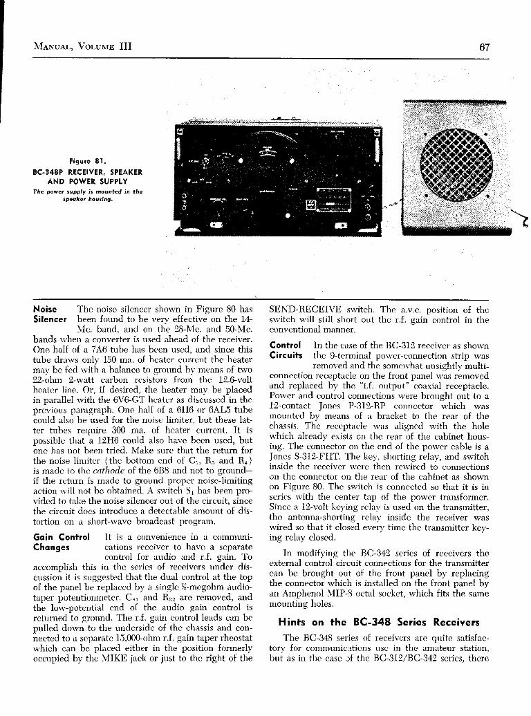
MeNuar-. Vor-uvB III 67
Figure 81 .
BC-348P RECEIVER, SPEAKERAND POWER SUPPLY
fhe pover supply is mounted in thespeoker housing.
Noise The noise silencer shown in Figure 80 hasSilencer been found to be verv effective on the 14-
N'fc. band, and on the 28-NIc. and 50-Mc.bands r.vhen a converter is used ahead of the receiver.One half of a 746 tube has been used, and since thistube drarvs only 150 ma. of heater current the heatermay be fed with a balance to ground by mearrs of two22-ohm 2-watt carbon resistors from the 12.6-voltheater line. Or, if desired, the heater may be placedin parallel with the 6V6-GT heater as discussed in theprevious paragraph. One half of a 6H6 or 6AL5 tubecould also be used for the noise limiter, but these lat-ter tubes require 300 ma. of lieater current, It ispossible that a 12H6 could also have been used, butone has not been tried. Make sure that the returt forthe noise l imiter (the bottom end of Cr, Rr and Ra)is made to the cathode of the 688 and not to ground-if the return is made to ground proper noise-limitingaction rvill not be obtained. A srr'itch Sl has been pro-vided to take the noise silencer out of the circuit. sincethe circuit does introduce a detectable amount of dis-tortion on a short-wave broadcast program.
Goin Control It is a convenience in a communi-Chonges cations receiver to have a separate
conuol for audio and r.f. eain. Toaccomplish this in the series of receivers under dis-cussion it is suggested that the dual control at the topof the panel be replaced b1, a single )ó-megohm audio-taper potentionmeter. Cir and R32 are removed, andthe low-potential end of the audio gain control isreturned to sround. The r.f. gain control leads can bepulled dorvn to the undersidé of the chassis and con-nected to a separate 15,000-ohm r.f. gain taper rheostatrvhich can be placed either in the position formerlyoccupied by the MIKE jack or just to the right of the
SEND-RECEIVE su'itch. The a.v.c. position of theswitch u'ill still short out the r.f. sain control in theconventional manner.
Control In the case of the BC-312 receiver as shorvnCircuits the 9-terminal por,ver-connection strip was
removed and the somewhat unsightly multi-connection receptacle on the front panel was removedand replaced by the "i.f. output" coaxial receptacle.Power and control connections rvere brought out to a1,2-contact Jones P-312-RP connector which wasmounted by means of a bracket to the rear of thechassis. The receptacle was aligned rvith the holewhich already exists on the rear of the cabinet hous-ing. The connector on the end of the power cable is aJones S-312-FHT. The key, shorting relay, and switchinside the receiver were then rewired to connectionson the connector on the rear of the cabinet as shownon Figure 80. The srvitch is connected so that it is inseries with the center tap of the porver transformer.Since a l2-volt keying relav is used on the transmitter,the antenna-shorting relav inside the receiver waswired so that it closéd "r,"iv ti*" the transmitter kev-ing relay closed.
In modifying the BC-342 series of receivers theexternal control circuit connections for the transmittercan be brought out of the front panel by replacingthe connector which is installed on the front panel byan Amphenol MIP-8 octal socket, which fits the samemounting holes.
Hints on the BC-348 Series ReceiversThe BC-348 series of receivers are quite satisfac-
tory for comrnunic:rticns use in the amateur station,but as in the case rf the BC-3I2/BC-342 series. there

68 Sunplus Remo Couvpnsrom
Figure 82,REAR VIEW OF THE BC-348P
ASSEMBLY.Showing the powet supply mountedin the spoker housing and theoclat poweÌ piug on the eeceiver,
are several minor modifications lvhich may be madeto improve the performance and flexibilitv of theequipments,
BC-348Q Generol The BC-348 series of receiverslnformqtion miiy be operated rvith the heater
circuits unchanged from a 26-volt a.c. supplr'. But a porver transformer rvith such afilament rvinding is not rcrrdilv availarble (erlthough theC-228 transformer mentioned in connection with theBC-3I2 may be used rvith the filament rvindings inseries ) so it is in most cases best to rervire the heat-ers for operation from 6.3 volts. This means that oneside of the heater of each tube should be sroundedand the other side should be broueht out ai a com-mon for feeding from the 6.3-r'olt line. In many casesthe orieinal "sèriesins" rvires betrveen tube socketsma.v be used either fòr the grounded side or the hotside of the l.reater circuit, recluiring addition of ferverwires and a solution to the problem of rvorking incramped spaces.
The a.c. power supply for the receiver may bemounted in tl.re space formerlv occupied bv the dyna-motor if space considerirtions and portability are veryimportant. Hor.r'ever', this procedure is not desirablefrom the stilndpoint of ventilation since an a.c. powersupply dissiprrte's .ì great deal more heat than the dy-namotor origintrlly instnlled. The spnce is more usefulfor additions to the receiver such as a noise limiter,an extri.r audio stage, or a broad-band converter.
The externarl a.c. operated pou'er supply may bemade somew'hat oversize for operation of a frequencymeter or a converter or an additional station accessory.In this event it is desirnble to be able to ground thenegative leacl of the plite supplv, rvhich is not doneon the BC-348Q. It is necessauy to change the bias
circuits of the 6K6-GT audio stage and the 65A.7 con-verter to accomplish this. The first step is to groundthe B minus and remove connections to choke 155-Band resistor 108-2. This leaves both the above stagesunbiased. A 470-ohm 2-u'att resistor should be placedin series u'ith the cathode terminal of the 6K6-GTaudio strrge. A 25-r'olt 25-pfd. electrolytic capacitorshould be pliiced ircross this cathode resistor.
About 1.8 r'olts of biirs is used on the grid of the6547 convcrter stirge. To obtain this, resistor l0B-1in the cscillirtor can should be clipped out of the re-ceiver. The contact at the junction of this resistor andresistor 87-2 is available as a projecting lug. Lrpon thislug mav be mounted a standald miniature bias cellrvith thc positÍve side grounded trnd the negative sideto the lug.
Audio Addition of a noise-limiter (seeConsiderotions Radio Hotttlbook) rvil l improvein the BC-348Q operation in the presence of igni-
tion interference on the 14-Mc.band and is almost a necessitv for use of the receiverrvith a converter on the lS-\ic. or 50-\lc. bands. Theaddition of an extra stage of auclio is also desirable.especiallv for use rvith thc cn'stal filter on 14-Mc. c.w.Tlie added tube mav be a 6SF5 triode with conven-tional circuit valuers (see iinv standard reference), ora 6SJ7 stage u,ith feeclback'mru' be added.
Difficultl'mav bc ctrcottntered rvith the audio sys-tem of the receiver afti'r the addition of the audiostage and the noise lirniter due to the common cathoderesistor on the second detector and the third i.f. stage.This trouble m:ry be avoided bv isolating these twocathode circuits. The lead betrveen the two cathodesis rernoved and resistor 105 is either removed or short-

MeNuer.. Volulrr III 69
I
ed. This leaves the third i.f. stage with resistor 102and capacitor 6l-4 in its cathode circuit to ground.The cathode of the second-detector tube is nowgrounded to the chassis. The large capacitor can 70-Aand 70-B may now be removed to make additionalroom inside the equipment. The 6-pfd. section is idealas a portion of the filter capacitance in the externalpower supply. The lead -at the low-potential side ofthe third i.f. transforrner should be opened and thenoise limiter inserted at this point. Capacitor 27-3should be left to by-pass the secondary of the trans-former. The on-off switch for the noise silencer may beplaced in a panel position in place of one of the head-phone jacks.
Mechonicol If a plug to fit the rear connectorConsiderqtions block cannot be secured, an octal
socket may be fitted into the set byliberal use of a round file and then by drilling andtapping mounting holes for the socket. If the castaluminum guide box is removed from the case it wíllnot be necessary to enlarge the rectangular hole inthe case to pass an octal power plug,
A socket punch may be used to make two holes inthe back of the case. One hole is used to pass the plugfor the speaker connection, and the other hole to reacha two-post terminal strip which is rvired to the receiv-er silencing circuit (terrninals 2 and 6 in the circuitdiagram ). These two terminals may then be shortedor wired into the transmitter control circuit in such amanner that the receiver is disabled whenever thetransmitter is on the air.
The seriesed dial lamps should be parallel andconnected to the 6.3-volt heater circuit with the dia-llight control resistors lll and 81 out of the circuit.
BC-348E, M, Changes in this series of receiversond P Receivers are generallv the same as in the
(J ) , (N ) , and (Q) se r i es o f 348 ' s ,except that onlv the porver audio stage must be modi-fied when grounding the negative lead of the powersupply. Also, tlie second detector arnd third i.f. stagecannot be isolated since they are in the same tubeenvelope.
Fisures 81 and 82 show a convenient methodwherety the power suppll' for a BC-3'18 series re'ceiver may be mounted in the housing for the loud-speaker.
A 120 to I40 Wott Modulotor from theBC-375 or BC-I9l
One way in'ivhich to solve the problem of makinggood use of the BC-375E or the BC-f91 is to dis-àssemble the tr-rning drawers for components, use thehousinss for the tuning drawers as cabinets for ac-""trory'pieces of test èquipment, and use the mainhousing of the transmitter along with the audio trans-formeri and miscellaneous other components to as-semble a modulator. Figures 83 and 84 show one suchassembly which operates quite satisfactorily.
Figure 83.
MODULATOR AS MADE FROM A BC-375E.lhe ,ront cover hos been removed lo srtov trte placement ol
componénts on úhe nev chassis.
All components on the upper deck were removed,including the chassis, and a new chassis was bent fromsheet aluminum to hold the components shown inFigure 85. The end of the main housing which heldthe antenna tuner was sawed off as unnecessary, butit might be retained to house the power supply for themodulator if components of the proper dimensionsshould be obtainable. The components mounted on theupper deck of the chassis include the power supplyfor the speech amplifier, a simple regulated bias cir-cuit for the negative 100 volts on the 2ll grids, andthe audio transformers.
The clipper-filter audio amplifier and driver ismounted in the housing for one of the tuning drawersafter alì the r.f. components had been removed' Thecircuit for the speech amplifier is shown in Figure 86.An additional panel rvas placed in front of the originalpanel to covel the multitude of holes that had beenieft by removal of the r.f. components. The clipper-filter speech amplifier is quite conventional, endingin a single-ended 684-G which acts as driver for the2ll's. Provision has been made in the input circuit of

70 Sunpr,us Renro CoNvsnsroN
AN/ART-I3 Autorune Aircroft RodioTronsmitter
The AN/ART-l3 Autotune aircraft radio trans-mitter makes a very satisfactory amateur transmitterfor phone and c,w. operation on the 80, 40, 20 and 10meter bands. Under normal conditions the transmitteroperates yery stably and puts out a cleanly modulatedor smoothly keyed signal rvhen it is running about200 watts input. The Autotune feature is a great oper-ating convenience rvhether the tr:rnsmitter is to beremotely controlled or controlled from the operatingposition. lVith the circuit modifications describeàherein the Autotune system allou's operation on l0 pre-set frequencies throughout the 80, 40 and 20 mèterbands and one additional frequencv in the l0 or Ilm^eter ba-nd. Operation with phone or c.w. on any oneof these frequencies i,s obtained simph' bv rnoving thepanel selector srvitch to the desired position-andwaiting approximately 25 seconds for the Autotunesystem to operate. If desired, several frequencies sep-arated by not more than about 50 kc. màv be set ripin the 28-Mc. band with an increasine r'eduction ilthe frequencies available for lower frequency opera-tion.
wFigure 84 .
REAR V]EW OF THE BC.375E MODULATOR.
the speech amplifier for both a single-button micro-phone and a cry'stal-microphone input, with a switchS to select either input circuit. The clipping level con-trol R1a, must be substantially full open for maximumundistorted output from the 9ll tuÈes in the outputstage.
Measurements of the complete modulator, with a1250-volt power supply feeding plate voltage to the2ll tubes, showed that it was possible to obtain 120watts of audio output from the tubes with no distor-tion discernible to the ear or noticeable on the oscillo-scope. An output of I45 rvatts rvas obtained with anamount of distortion rvhich r.vould be quite tolerablefor amateur communications work. No heatins of theoutput transformer was noticed rvith 120 watti outputfrom the stage into a 7000-ohm load resistor over atest lleriod of about one hour.
The 7000-ohm load impedance could be represent-ed by a Class C modulated r.f. amplifier operatingfrom the same plate supply as the 211's (1250 volts)at a plate current of 180 rna. This represents an inputoÎ 225 watts to the Class C stage, an amourrt whichmay be modulated without difficulty by the modula-tor unit.
P L A î E + 9 - 8 i t 5 v . ^ . c .ca4G
Î O S P E € C H A M P L I F I E R
FíEure 85 .MAIN ASSEMBLY SCHEMAT]C OF THE BC-375E
MODULATOR.C' -8-p fd . 45O-yo l t e lec t .Ct-40-pld. 35O-yolt elect.C: , Cr -8- i r fd , 450-Yo l t e lec t .Rr - l00 ,000 ohms Y ' wqt tR ' -7500 ohms Io là r tsR, -5000 ohms l0 wot tsR, -50 ,000 ohms 20 wot tsTr -Dr iver t rons . f rom 375ET"-Mod. trons. from 375ETr-10-vo l t ó .s -omp. f i l , t rons .
Tj-700 v. c.t. 90 mo., 5 v. 3o . , ó .3 vo l ts 2 omperes
C H - 1 2 - h v . 9 0 - m o . c h o k eMA-0-500 d .c . mq. f rom 375EV-Voltmeter f rom 375ESr-Phone c .w. sw i tch f rom 375ES"-Moin o .c . l ine swi tchS,-S.p.s.t. test switchSOr, SO-Twistlock receptocles
î-cr \y_,,
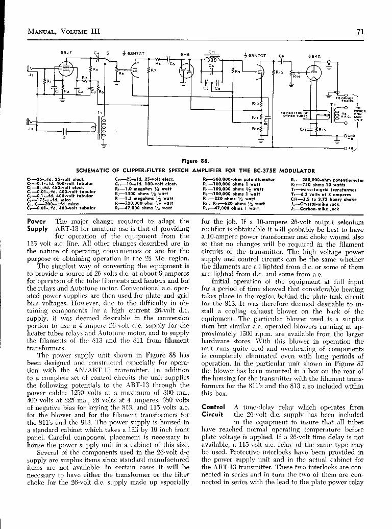
MeNuer.. Vor,uur III 7L
SCHEMATIC
Ct-25 - pÍd. 25-Yolt elst.Cu-0 .1-g fd . 400-Yo l t tubu lo lCr-8-pfd. 45O-volt elect.Cr-0.0.| -pfd. 400-volt tubulorC: -0 .1 -p f d . 400-vo l t tubu lo rQel75-ppÍcl. micoCt, Cs-2O0-ppfd. micoCr-0.01 -pfd. 400-volt tubular
{ osNzcr{ osrzcr
Figure 86.
OF CLIPPER-FILTER SPEECH AMPLIFIER FOR THE BC-375E
Rr500,000-ohm potentiometetRr - l00 ,000 ohms I wot tR\-100,000 ohms /2 ìrottR ! -100,000 ohms I wot tRre330 ohms !/2 wottRrr, Rr:-ó20 ohms y2 vottRrr--{7,000 ohms I wott
IO H€ATERS OFOTHÉR fUA€3
MODULATOR
Rrr-250,000-ohm potentiometelRrs-750 ohms l0 wottsTr-Mike-to-9rid tronsformelTr-ó.3 volts ol 3 omperesCH-3.5 to 3 .75 henry chokeJr-Crystol-míke iockJ-Corbon-mike jock
Ctr25-ufd. 25-Yolt elect.Crr-l O-pfd. I 0O-volt elect,Rr-ì.0 megohm /2 vottRr-1300 ohms 72 wottRr - I .5 megohms V2 vo t tR,-220,000 ohm 72 vottR5---47,000 ohms /2 vott
Power The major change required to adapt theSupply ART-13 for amateur use is that of providing
for operation of the equipment from the115 volt a.c. line. All other changes described are inthe nature of operating conveniences or are for thepurpose of obtaining operation in the 28 NIc. region.
The simplest way of converting the equipment isto provide a solrrce of 26 volts d.c. at about 9 amperesfor operation of the tube filaments and heaters and forthe relays and Autotune motor. Conventional a.c. oper-ated power supplies are then used for plate and gridbias voltages. Horvever, due to the difficulty in ob-taining componcnts for a high cnrrent 26-volt d.c.supply, it was deemed desirable in the conversionportion to use a rl-amperc 26-r-olt d.c. supply for theheater tubes lelal's rincl Autotune motor, and to supplytlie filaments of thc 813 and thc 811 from filamenttransformers.
The pon'er supplv unit shou.n in Figure 88 hasbeen designed and constructecl especially for opera-tion with the AN/ART-I3 transmitter. In addítionto a complete set of contlol circuits the unit suppliesthe follou'ing potentials to tl-re ART-13 through thepower cable: 1250 volts at a miìximum of 300 ma.,400 volts at 225 ma., 26 volts at 4 amperes, 350 voltsof negative bias for keying the 813, and 115 volts a.c.for the blorver and for the fil:rment transformers forthe 811's and the 813. The power supply is housed ina standard cabinet which takes a 121í bv 19 inch frontpanel, Careful component placement is necessary tohouse the power supply unit in a cabinet of this size.
Several of the components used in the 26-volt d-csupply are surplus items since standnrd manufactureditems are not available, In certain cases it rvill benecessary to have either the transformer or the filterchoke for the 26-volt d.c. supply made up especially
{or the job. If a 10-ampere 26-volt output seleniumrectifier is obtainable it will probably be best to havea l0-ampere power transformer and choke rvound alsoso that no changes will be required in the filamentcircuits of the transmitter. The high voltage powersupply and control circuits can be the same whetherthe filaments are all liehted from d.c. or some of themare l ighted from d.c. irnd some from a.c.
Initial operation of the equipment at full inputfor a period of time showed tl.rat considertrble heatingtakes place in the region behind the plate tank circuitfor the 813. It s'as therefore dcemed desirable to in-stall a cooling exhaust blorver on the back of theequipment. The particulirr blorver used is a surplusitem but similiu a.c. operated blou'ers running at ap-proximately 1500 r.p.m. are avnilable from the largerhardware stores. \\zith this blorver in operation theunit runs quite cool and overheating of componentsis completely eliminated even rvith long periods ofoperation. In the particular unit shown in Figure 87the blower has been mounted in a box on the rear ofthe housing fol the transmitter rvith the filament trans-formers foi the 811's and tlie 813 also included withinthis box.
Control A time-delay reìay rvhich operates fromCircuit the 26-volt d.c. supply has been included
in the equipment to insure that all tubeshave reached norrnal operating temperature beforeplate voltage is arpplied. If a 26-volt time delay is notavailable, a 115-volt a.c. relav of the same type maybe used. Protective interlocké have been oro.'ìd"d ittthe power suppìy unit and in the actual ìabinet forthe ART-13 transmitter. These trvo interlocks are con-nected in series and in turn the two of them are con-nected in series with the lead to the plate porver relay

72 Sunpr.us Reoro CoNvnnsroN
Figure 87.
TOP OF THE CONYERTEDAN/ART- I 3 .
The boy. contqinìng the btover dndthe l i lomenl ttonslormets lot lhe813 ond t f ie 8 t t ' s cqn be seen onthe tesr olongside the smoll boxvhich holds the 6L6 multiplier Íorthe 28-Mc, bond. I�hè 28-Mc. tanklot the 813 csn be seen inside trre
Cdbinet.
RYl so that plate voltage cannot be applied to thetransmitter if the cover has been removed from theART-13 or if the top door to the power supply boxhas been opened.
Provision has been made in the control circuit forthe transmitter so that when S111y on the front of theART-13 or its counterpart at the remote control posi-tion is moved from the off to either the voice or thec.rv. position, the transmitter will be turned on. Sincethis switch closes a circuit to ground, it was necessaryto find an isolated source of potential to operate themain control relay. This source of potential was ob-tained by leaving the small transformer Ta connectedacross the line at all times that the unit is plugged intothe socket. However, when the transmitter is switchedoff there is no power drain from any of the secondariesof this transformer.
The push-to-transmit circuit which has been in-cluded in the power supply unit is very pleasíng tooperate and relatively simple in design. It consists ofa single 6C5 tube operating from the bias supply alongwith its associated components. The complete circuitis shown in Figure 88. When the key is up relay RY;is open and the voltage drop across R; to the slideris impressed cn the grid of the 6C5 tube, cutting offits plate current. When the key is pressed RY5 closes
and the right-hand side removes the blocking grid biasfrom the 813 by shorting the grid return to groundthrough Re and CH6. These lutter tu'o componentsin conjunction rvith Cs make up .ì \'en' effective key-click filter. The effectiveness of the circuit is illustrat-ed by the fact that clicks cannot be heard from thetransmitter on a communication rcceiver tuned to thesame band for break-in c.rv. operrrtion.
At the same time that RY.; is closir.rg, the other setof contacts on this relay shorts thc grid of the 6C5to its cathode, causing full plirte current to flowtìrough RYo and Rr, thus cìosing RYa. When RYacloses the antenna chanqeover relav in the ART-13operates and plate voltage is iipplieé to the transmit-ter by RYr. Then when thc ker. is lifted RY5 opensso that plate current to the 813 is stopped, but dueto the time constant of tlie R,;-Cc combination, platecurrent still flows through RY,;. Hence the plate volt-age remains on the transmitter and the antenna relayis still in the transmit position. The transmitter re-mains in this condition until the voltage across C6 hasbuilt up to such a value thtrt RY6 drops out, changingeverything back to the receive condition. The amountof this delay is variable, by adjustment of potentio-meter R;, from a fraction of a second up to about 15seconds. The normerl setting is for about 3 seconds so

MaxuAL, Vor,urtm III 73
iI l '*)
* e '
Ct, Cr-4-pÍd. | 500-voltcopocitofs
Cs, Cr-4-pÍd. ó0O-voltcoPocitors
Cs-l O-p"Íd. óOO-volt coPocitor
Cc-0.5- pÍd, 600-volt tubulor
Cz-0. t -pfd. 400-vol t tubulorCs-0.05 -pfd, 400-volt tubulorCs-499O-p,Íd. 50-volt elect.Cro-8-rrfd. 450-volt elect.R1-50,000-ohm | OO-wott
bleederRz, Rr-22 ohms 2 wotts
R{-10,000 ohms l0 wottsRs-l 00,000-ohm PotentiometerRc-2.7 megohms y2 wottRT- !5 ,000 ohms l0 wot tsR\-50,000 ohms 20 wottsR,,-15,000 ohms 2 wottsTr- t 500 v. eoch side ot 300
rno., 400 v. eoch side ot175 lno . r common c . t .( urc PA-303)
T:r-5 v. 3 c. , 2.5 vol ts l0 o.Tr -700 v . c . t . 70 mc. , 5 v .2 o . ,
ó .3 v . 2 o . (UTC R-2)Ts-35 yol ts ot 5 q. (speciol)
CHr-250-mo. swinging chokeCHz-250-mo. f i l ter chokeCH:r, CHr-200-mo. f i l ter chokesCHs-0.05 henrys ot 4 omp.
(speciql)CHe-l 3-henry óS-mo. f i l ter
chokeRYr-28-volt d.c. 4-pole d.t.
re loyRyz-l | S-volt q.G. 2-Fole relcyRYs-ó.3-volt or 5 volt 2-Pole
reloy (RYz ond RYs mcY becombined if conto€ts aÍ
+ 2 6 V .
5 V .
STANO6Y
H . V . O N
ANTENN/C H A N G E
O N . O F F
1 f 5 V .
O-+26 V.
P L A T E
6 r 3a t A s
+400 v.
- f i3 V .A.C.
RYs con cqrry obout 8ompefes ond if 3 Gontoctsore ovo i lob le . )
Ryr-28-yolt d.c. t ime-deloy re-loy ( l lS-vol t o.c. t ime-de-loy relqy msy be usdccross Primory of Ts iÍ 28-volt reloy not ovoiJ.)
RYs-28-vol t d.p.d. t keYingfeloy
RYc-2500-ohm sensitive reloyElimstot-A.c. l ine fi l ter
C s C H t l C c C H a l C s
I NTERLOCK
Figure 88.
SCHEMATIC DIAGRAM OF THE POWER SUPPLY FOR THE AN/AR,T.I3.
that the plate voltage will remain on for the normalshort pauses in a c.lv. transmission but will drop backto the receive condition 3 seconds after a transmissionhas been completed.
Chonges in It is necess ary to make a certainART-I 3 Control number of modifications in theCircuits various circuits of the ART-13 in
order to allow the equipment tooperate from the power supply unit described before
rna illustrated in Figure 88. It is necess ary first thatthe meter switch circuit be changed in the followingmanner: Remove ground from bottom end of Rrrt(235-ohm resistor ) and connect this end of the resis-
tor to terminal A2 of Sron. Remove the wire that nowgoes to terminal Bs of Srnn and connect this wire to
lerminal Az of Sror along with the bottom end of
Rr' above. This series of changes brings the gridreturn of the BI3 tube out to terminal 2 on the mainpower Connector Jtoa.
The following changes are required in the powercontrol circuits: Ground the lead inside the cabinetwhich now goes to terminal 8 on fros. Remove thelead now going to terminal L4 of Jrra which is mountedon the side of the antenna changeover relay Kror. In-sulate this lead. Now run a lead from terminal 8 of |rosto terminal 14 of Jrru. A lead is now run from terminal2 on the loading coil relay connector jroz to terminalC in the power supply unit. This is the only leadbrought out of the transmítter which does not gothrough the main power connector Jros.
Tlie filaments of the 813 and of the 811's shouldbe re-wired to operate from separate transforrnersmounted on the rear of the equipment. One side of

74 Sunpr,us Ranro CoNvnnsrow
the filament may be left grounded on the 818 but thecenter tap of the filament supply to the 811's must begrounded in order to eliminate hum modulation onaudio peaks. The primarv of the filament transform-er and the cooling blower for the equipment shouldnow be connected to terminals 6 and g on Jros. Theseterminals are supplied rvith 115 a.c. from the powersupply unit rvhen the equipment is in operatio;. Thedriver transformer returns which formerly went to oneside of the filament of each 811 are now grounded. tothe chassis of the transmitter.
Several changes may be made in the viciniW ofthe high-frequency,/lorv-frequency relay K1,r; whetheror not the lO-meter band is to be included in thetransmitter. In [he first place the low-frequency chokeLro-c Tay as well be removed from its present positionand Cr:s mounted in the space formetly o"c.,pbd byLrosr. One additional hole must be drilled in the firervall of the equipment. It is suggested that a protectiveinterlock norv be mounted in the position formerly oc-cupied by Cr5 on the fire wall of the transmitter. Theleads to this interlock should be connected in serieswith the lead now going to terminal 3 of Jr63. Theinterlock should of course be mounted in such amanner that it is closed onlv when the cover is firm-ly in place on top of t lre transmitter.
A slight increase in operating convenience can beobtained through replacing the 0-5 r.f. ammeter witha 0-300 or a 0-500 d.c. milliammeter. The r.f. trans-former T162 ma! be removed after the leads have beenclipped by unscreu'ing it from the chassis. \Vith theinstallation of this additional milliammeter it is possi-ble to read grid current and plant current on thè 813simultaneously.
Converting for The conversion of the ART-1328-Mc. Operotion for 2B-N,Ic. operation mtry, be ac-
c'omplislred in several úifferentrvays of varying difficulty. Horvcver, in converting the
unit showrr in the photographs it was felt that a con-version method which did not involve any dis-assem-bly of the Autotune mechanism and which reouiredno changes in the exciter of the transmitter *oúld b"best. So it was felt best simply to add a 6L6 outboardtripler stage on the rear of the transmitter in the vicin-ity of the grid of the 813. The 6L6 tripler is fed energyfrom the 1625 second mr,rltiplier in tlìe ART-I3 in tÉe9-.0 to_ 10.8 Mc. frequency range. The plate circuit of1!e 6L_6 then may, be tuned to ìnv freqìency between27 and 32.4 Mc. for feeding excittrtion to tire grid ofthe 813 amplifier. In fact, il desired, the 6L6 riay beused as a doubler from the same frequency range todeliver excitation to the grid of the gi3 in lhe Zt"-Mc.range.
The 6L6 multiplier is housed in 2,, by 4,, by 4,,standard metal "cabinet"
which l"ras been mountedto the side of the cabinet which houses the blolr,er andthe filament transformers for the 811's and 813. 51 inthe circuit diagram of the multiplier, Figure gg, maybe either a double-pole double-throw ceramic srvitchor a 28-volt d.p.d.t. relay which may be operatedfrom the 28-volt supply for the transmitter. In theparticular unit shown in the photographs a switch isused but it is planned to replace [hJ switch with arelay for completely remote operation of the trans-mitter. The relay will be operated by another set ofcontacts on the channel-selector switch which rvill beclosed whenever the 28-\Ic. band is chosen. Heatervoltage for the 6L6 mav be obtained from a smalltransformer or from the suppll' for the 811's if theyare operated from a.c.
The circuit of the 6L6 multiplier is otlierwise quiteconventional except for the mìnn"r in u'hich ilatevoltage is obtained for the 6L6 multiplier. Carefúl in-spection of the circuit diagram of the ART-13 willshow that the 400 volts appliecl to the plate of the1625 multiplier appears actoss onlr- onc. scction of theptrdder capacitor C11; at a time ancl onlr. rvhen thatparticular section of the paddt'r citp.rcitor is in use.H9n9e, by connecting an r,f. chokc to padder capacitorrvhich is used to excite tlie grid of tlie 6L6 in ihe g.Oto I0.B N{c. range, 400 volts front tlie exciter powersupply may be obtained bv filtcrinq tlie r.f. out if thed.c. line rvith an r.f. choke .uid ir br -pirss capacitor. A50-irpfd. mica capacitor is the.n used to excite the eridof the 6L6 multiplier frorn tlie liot side of the r.f.choke. In this way the 6L6 multiplic'r is completely outof the circuit except rvhcn control A is in position g.
The lead from couplinq crìpacitor C116 to the gridof the 813 is broken and a lead brought out from eachside of the point rvhere tlre connéction is broken.These two leads are then connected as shown in Fie-ure 89 to the 6L6 multiplier unit. One set of contac{son 51 is used in addition to close K1s;, which switchesthe plate of the 813 from the network used on thelow-frequency bands to the separate 28-NIc. tank
1 7 4 . 2 W , , R E S T S î O R ,o L o 1 5 1 . N . 2 4 A R O U N O I t
7 î . N.J4 3/4'D I A , f " L O N C
Î o c L o s € K - t o 3
........-6.3 V. tO 6LO HE^T€R-
F igu re 89 .
SCHEMATIC OF THE 28 .MC. MULT ]PL IER STAGE.

I CMewull, Vor,uur III
Figure 90.SCHEMATIC OF THE SIMPLE
LM POWER SUPPLY.îha s-vott and 6.3-volt windings on ment voltaEe meosqres about ll.9the trdnsrormer dre connected in vot-ts on the lilomenl lead. Thisseries ro obtaìn titament vottase íi,y;.#'rt:ÍflZ|'i"Yr?!:r{!,:î il:"ior the LM. Due úo úhe lìght lo.ad ;;;i;;";"È;';;;
-i;-ii,;-ìrr;L";;i
on the lilament vindìngs the lilo- Meter.
rrgure I I
PHOTOGRAPH OFTHE SIMPLE LMPOWER SUPPIY.
An LM frequency mete' isshovn olongside the power
supply lor compoúson.
which has been placed in the position inside thecabinet of the ART-13 which was designed to holdthe low-frequency oscillator unit. In the particulartransmitter shown the 2B-Mc. tank for the BIB con-sisted of a 6-turn coil of number l0 enamelled wire lliinches in diameter and Lló inches lone. A two-turnlink feeding a piece of 300-ohm line is then run overto the left wall of the transmitter where it terminatesin a pair of terminals. With this tank the 8lS dips toabout 30 ma. on 28 Mc.
The two terminals which close K165 may be pickedup as terminals 7 and 4 on the connector Jrrs whichfeeds plate and filament supply to the multiplier unitof the ART-13. Two leads from these two termin-als are run to the 6L6 multiplier unit so that they areclosed whenever the 6L6 is in operation. With the 6L6frequency tripler as shown it is possible to obtain halfscale on the grid current meter throughout the 2B-Mc.band; this represents about 8 to g ma. of grid currenton the 813.
Note in Regord The output network ofto the Outpur the AN/iRT-I3 is de-Network of the ART-13 signed to operate as an"L"
network on freouen-cies up through about 5 Mc. This is required sincè thetransmitter was designed to feed an antenna installedon an aircraft which would have a verv low radiationresistance at these low frequencies bui would. have arelativeìy large value of capacitance to ground. Thisnetwork will not feed satisfactorily the type of an-tennas commonly used by amateurs for fixed-stationuse in the 3.5 to 4 Mc. beutd. Hence it is desirable toconvert the L network into a pi network when operat-ing on the 8O-meter band. The simplest way io dothis is merely to place a capacitor of 100 to 4b0 pg.fd.from the -COND"
terminal on the left end of thetransmitter to the ground terminal on the case. Avariable capacitor may be used to determine the bestvalue for this capacitor, and then a fixed air capacitoror a ceramic transmitting capacitor of the type usedin the transmitter may be hooked in place. Experiment

76 Sunpr,us Reoro CoNvrnsroN
showed that a value of about 200 ppfd. was best forfeeding a folded dipole with 300-ohm twin line onthe 3.5-NIc. band.
Tests of the completed transmitter have shown thatthere is no appreciable increase in output after theplate current on the 813 is increased above 160 ma.This represents a power input of 200 watts at 1250volts and the plate circuit efficiency runs from 70 to75 per cent on all bands. The out-of-resonance platecurrent rvill be from 180 to 200 ma. with normal exci-tation, and antenna coupling should be adjusted until160 ma. of plate current is drawn by the 813 tube.
Simple A.C. Power Supply for the LMFrequency Meter
Figureq 90 and 91 illustrate a very simple powersupply for operation of one of the LN,I series frequen-cy meters from the 115-volt a.c. line. Plate voltage forthe frequency meter is obtained from a small powertransformer s'ith a 6X5-GT rectifier. Due to the verylow plate current requirements of the frequency metera resistance-capacitance filter has been used on the
plate voltage supply. With ihe transformer shown andthe values of resistance and capacitance listed theplate voltage supplied to the frequency meter is 255volts. This voltage is sufficient to cause the neon regu-lator tubes to strike with certainty when the voltage-change strap in the LM is adjusted to the 200-260-voltposition.
By connecting the trvo filament windings on thepower transformer in series it is possible to obtainadequate heater voltage for the frequency meter. Dueto the light load on these two filament windings thevoltage applied to the LNI under normal operatingconditions is 11.9 volts; this value of voltase is wellwithin the plus or minus 10 per cent heatèr voltagelimit on the tubes used in the equipment. Through theuse of a 6X5-GT rectifier, rvhich has the heater wellinsulated from the catlode, the rectifier may be light-ed from the same filament rvindings, rrùich lieht thetubes in the frequency meter. No changes rvÉateverare required inside the LM frequencv meter rvhen itis used with the power supply shown in these illus-trations.
L r s T o F E Q U T P M E N Ton which dsto is given in Volume I of the
"Surplus Rodio Conversion Monuol"
BC-221 Frequency Meter
BC-342 Receiver
BC-312 Receiver
BC-348 Receiver
BC-412 Rodor Oscilloscope (Conversions forTV Receiver ond Test Oscilloscope)
BC-ó45 Tronsmitter-Receiver (420 Mc.)
BC-9468 Receiver (Conversion to Auto Receiver)
SCR-274N (BC-4534 Series) Receivers(Conversion to I O-meters)
SCR-274N ( BC-4574 Series) Tronsmilters(Conversion to V.F.O.)
SCR-522 (BC-ó25) Tronsmitter (Conversion to2 meters)
SCR-522 (BC-624) Receiver (Conversion to2 meters)
TBY Trsnsceiver (Conversion to l0 ond ó meters)
BE-1034 Dynomotor
BC-10ó8A/t ló lA Receiver (2 meters)
L t s T o F E Q U T P M E N T
on whiéh doto is given in Volume l l of the"Surplus Rodio Conversion Monuot"
ARC-5 (8-454) Receivers (Conversion to 28 Mc.)
AN/APS- I 3 Tronsmitter-Receiver(Conversion to 420 Mc.)
ARC-5 (BC-457) Tronsmitters (Conversions to28 Mc.)
Selenium-Rectifier Power Units
ARC-5 V.H.F. Trqnsmitter-Receiver Operot ion
GO-9ITBW Tronsmitter (Conversion to 28 Mc.)
BC-357 Morker Receiver (Conversion toCopocity Reloy)
BC-9468 Receiver (Conversion toHigh-Fidel i ty Tuner)
BC-375 Tronsmitter (use with externol V.F.O.)
T A-l2B / C Tronsmitter Conversion
AN/ART-13 Tronsmitter (Conversion to A.C.ond 28 Mc.)
Coi l -Winding Chorts
AVT-t l2A Tronsmitter for Light Aircroft
AM-26 / AaC Interphone Amplifier (Conversionto 9-wqtt Amplifier)
LM Frequency Meter
Beom Rotot ing Mechonisms
ARB Receiver (Schemotic only)

MeNuAL, Vor,ulrn III 77
I
I rual
. ì r |- ot -
z >1
tHot?
Iú)Iu
6aJ
< oN(vr l
a t9 9
t - s i l u
9 O t ?
tz t t u
l r
r_/\AtLJ? - 0 , ) l U
t - o i l u ! : r - g o r la r r . , r r l l I
t 0 l U
a o t c
n|I
! >; ot x
rîI
_ zr {
N 1o|ì
N:oay @
:I
; zo ?''
Ir 3 : :l ( v r I
@ { t '
l i : :. < > >
f - z
I
:c(,soIF
Ilrl-
c { ( JOl u!
o l; l
.9 lorr.
ÉÈ
z
Ful1^
coÉ
L)
r o tu9 O a u
Hr
; F-/w^- il, | '? + z ' c o r u t - t i l u y
i Z - g ' ) l U
i -Hf^-ir '.rl--,'MÀ-îl\ ît'*-iH,
t:u
r OR9Élff
f-
ú)I
IG
q+&.rff ;î ? oà O e- , -c- - J
l - t o € u z - t o c u
NN Oo at, (,J
dor'F
t ;l lI t
Il 1l 1l l
cOo'00
iI
oI
út
;
19
'r,- l
i eg t
/ órsu
Yrf r v2 o{ ;
f c - 9 0 t f4 /\ +{ }-r"*-!5!',
9 j t o t lI
.rHF'-
hr'?oTYu
î rg laìf IJ I
'ìoN-)
toN
c
J

7B Sunpr,us Reoro CoNvERsroN
-------ì
r t 0 2v r 0 t - ?a 4 6 . A
Il îl (ol ó
t ;IIl lI
L
?? ,c ,
IIIII
I2200ra
TG'ú
l. ;. Arf?Lrfre t
z l 0 l
l rII
t i lftst cAnActIoRS ARtAX nffnttr PAnT 0fTIII NSTTTLY AIO ART,IIOÎ IIIOIVIDUAtLY REPLACTAELE.
5 5 r C C o x v t R I t t
z t 0 2
H I G X T R T Q U I X C Y O S C I L L A T O R
MA&rf 0 wlTlt RtD Dorf l R S t 5 5 r C t r A u P L t F t t R
v r02- |x r04-rc A c 7
]
Z t o 5
f- -rTc,7
ì -
5 5 y C t f A u P L t t t t R
v t 0 2 - 2r | 0 4 - 26 ^ C ?" C 1 0 1 - |
< a al
I
z l 0 t
c t 0 4 - 2rl r
1 7 0 u u tqO 6
O o
J
470 uuF
\E 3
r000ulrFI tc .
r l t u l
CAIXOOT
cAftoDt r.f.coxltcÌlox
\ aq Po F_ P
!'--,, rr---- t
Y r 0 r - l4 4 6 - Ar t 0 l
Olt\
oolt'ètr0'uo:C
. I-toI
EoL
gf
.go
PLArr CAP I,PLATT R. t IcorrEcrrox i3:.T.-'�-tr'_r"i
;îtitAL Contcilots FotYto t . \Y to t -2 rv t0 t . t
ru l t w?[ 44 t .A
L-
Figure 93
RECEIVER UNIT, CPR.4óACJ, SCHEMATIC DIAGRAM
t:IIE
o
c
:.l'g:9 0ú,
!|rTLLtAst Yttì| sHo;ti6
Pt{ LocAttox
N*c
r{t9

MeNuAL, Vor,uprn III 79
t 6 t | C C 0 r { Y E R t t Ri t C O N O I 6 M C I F A M P L I F I T R
Y r 0 2 - ax t04 -4ó A C ?
I
r I R 5 T I 6 M C I F A U P L I T I E R
v t 0 2 - 5x l 0 a - J6 A C ? ['^ -l'lTrl
THIRD t6UC tT AYPLITTER
v t02 -7X l 0 / t - 76AC 7
z i l or--- :--ri 2 c t o . l - r I I
470UTF
coo:!
tîÉ
z t09v t 0 2 - 6x r 0 4 - 60 A c 7
U M F
;ao
9
4 7 0
\oo
l
470IIr
d3 E3 3 3 3 3 3 3 3 3 3 3 3 3 3 3 3 � J .
t iI| ,r.
l -!3: i
gP' _f
+ 2 ? 5 v D . c .
h3 v A .c .
Figure 93
RECEIVER UNIT, CPR-4óACJ, SCHEMATIC DIAGRAM
0.01) yî.\oo
I Io r 7
- I:-
T
- t
î ]\ lo '
3 l- l
- J7=oO No oa O -r o u
:o
r:E
a
I
c t 0 { - 3 "
? I U C O S C I L L A T O Rr t 0 4 - 3Y t 0 ? - 36 A C 7
Y t02- EI r 0 4 - 96À?.'t
f
:É.
III
I
i :r 9i -l n
o .=(É..
IIl ÌI El cI
lr
?
:e
::oo
9
I
€tl
9d.
r:l
o
8
'TI:3T'.fla \ J l r
. - : l
sT=.J-=-8
, (, Ét1' - (' e <
Y I D T O P O I T R O U l P U I
0 0 r M fR i l 3-4
Y t04x t04-t0
R i l 0 - E 0 A 6 7
\5
Io_ :
G
gÉ
n t c
0 u t

80 Sunprus Reoro CorvvrRsroN
#ff i
I
I
I
I
t- 6 rI
I
+ Nlo6 t,l (l F l
l r lI ? lT ? l
o lt ! l! l
v gv T - t 7 9R E C ' V R .
R . F A M P .
l {o . l
V 1
v T - t 8 2R . F P O I Y E R A M P
Y 2
vT - t 82TRANS. SUFFER
NOÍE:- O|IANNEL SwITCH (SrYg TO 51Y12)SHOWN IN ChANNEL 'B ' POSITION.
v5'v T - î 7 9R E C ' V R .
R . F A X PN O . 2
II
t t tGss Í '
clo
L
C : l
F
00
ooloèto
't'o3E
a -
a-toI
EoL
ol.9Ct
V 6
v T - 1 8 3R€C'VR. XTAL OSC.
1 l _s l l \TLL
g,T#
'îo-
%crJ
Figure 94
SCHEMATIC, BC-ó59 RECEIVER AND TRANSMITTER
V 9
v T - t 7 9R E C ' V R .I . F A M P

MeNuAL, Voluprc III 81
V 4
v T - t I cTRANS. REACT. ;{OO.
Vr3
v T - t 7 7R E C ' V R . O I O O € R E C T .
A OC AMP.
v 3v T - l E 5
TRANS. OSC.
I
I ICROPnOî{É Wf TH' P U S X - f 0 - î A L K '
s? lTcr {
t r tc z z
vro
v T - r 7 9R E C ' V R .I . F A M P
.lt-rf L E C Î
c A P l c t f o R
I'r
K E Y T O S Y M E O L S
F r r t o t r c ^O R C T R A X E
C A P A C T T O R
=ltrF
I
Y A N I A E L €A I R
/ ;aP/ rc t loR
IÈ-î,I
F I X E OP T P E R
c^PACt f OR
N O T E . - A L L C O I L S V I E W € D F R O MSOTTOM OF CHASSIS WITH FRONTP A N € L O N L E F Í
Figure 94
SCHEMATIC , BC .ó59 RECEIVER AND TRANSMITTER
R I Y € I

82 Sunpr,us Renro CoNvrRSroN
P - ?mAJ'JT-E-tl
S-28
L-27
240c-to
c- i l s-2 DPOWERAMPL
I xurR osc'/ v-4JAN - 3A5
REAGT TUBE
@I
J
ANTENNACONNECTOR
îr,Pl-Ú)l? l ;
;-tL
$l
ùo)
I
J
\t
òT;I
o,l I
r i- J
I M E G
R-46
,,1 DlscR
I\IAUDIO
D.C AMP|-v - t 7
JAN - IL4
st'I
(EDOUBLERv - 3
JAN-3A5
9I
3 n i
Ig 't O
--|r)TC)J . ? 240
c- r3
mlf,-f-ml
(oto
I()
R- t327K
GIq,
ooloc
Eo
'oa,tE
o -
3Eor,
EoL
ol.9o
r l - l r C )f J_(f)- G ro l oOI
=
c-56
o. r3 uFG - 9 3
-(\
POWER AMPLv - t
JAN.3A5
CRYSTALE OSC AMPLo v - t 4
; JAN- IL4
9 @
PòúìAI
CRYSTALoscv - t 5
JAN -3O4
R-36t o o K =
T O Y 4 . ? V D C
t
v-5l , r JAt t -3Q4
T O X O N J . 3 A
D I S C Rv - t 2
JAN- IA3
T O Zl /
POWERA M P L
v-2
cvP(J
L:)óo
î--JA N. 3A5
T R A N S M I T T E R F I L A M E N T S T R I N G
NOTE : CHANNEL SWITCH S-2A, S-28, S .zC, S-zD,S-zE, S-2F, S .zG, S .2H, S .2J SHOWN IN8 POSITION,
Figure 95
SCHEMATIC, 8C. I335.A, TRANSMITTER. RECEIVER
tr)G|ft
3P.: ó 7nlî.,' ( ) N
oF
Úl
?
POWERAMPL
rooc.?e s-zF
R -34I M E G
f,q;fii-1.NI
O
x'
:
-J zDRf ' l RIST RFAMPL If,
= v - 6 &JAN- IL4
- --
I S T I - F O
v - 9JAN-IL4
MIXERV-8 r\
JAN- lR5 îÉ.
5 8 5 C l 6
ilt
- \rt \)\
b.or ur
ltii
R-43 R -45
2 2 0 ; ' I v v q
flnnrr E1AS OSC=@+ R - 4 4 v - t 6 l ò'
uar.r-'iÉs +L - 2 9 =
=oJI F
; F oi lrJZl o i
3) D',BLERJAN -3A5
qql -BIAS oscV- I6 JAN-IRs
l o )I()
l!
J
ro
o

MeNuAL, Vor,ulnrn III 83
roîJ
s5frP()o
Nro
I
c
470
i l .ù, :
oCV
I(r' l 'e
ot-FtoL4
+2 DV-
J A N - I
T - 3O ) x
dÉa
5lc-f9
R-6 3 .5 x
- -- o -
UF
470 KR -50
c-?l
TO XMTR FIL STRING
R - 84 . 7 K
TO X ON TRANSMITTERFILAMENT STRING
+ { . 5 V
NEGATIVE TERMS
TO Z RECEIVERFILAMENT STRING
240c-52
DISCRv - t 2
l oINA I
I=
T-5
4 000
J - 3 8
[Ftr ]
JAN-IA33
v- t3JAN -3A5
Noo
ooì0c
EoL
r.r
't'ottr
jÉoI
EoL
olo
. I
o
-{(-l
c-38 =o . l 3 u F
-
8., -L{
B I A S C E L T 'BAT T ERY
lillllfr--:[tR -35470 K
lfo
ogtoc
Eo
!otEa-tEoI
EoL
ol.go
c-71 o o r-{Fa-
250
DISCRSECTI
T -6
J - 3 C
tFF t
M I X E Rv - 8
J A N . I R 5
lrf,
óo
oF
I
r\st&
DC AMPLv- t7
JAN - IL4
(
, ';Joscv - t 5
J A N - 3 Q 4
L I M I T E R ?D-t+ tsT l-Fv - t o v -9
J A N - I L 4 J A N - I L 4
IST R-F 2D R-Fv - 6 v - 7
JAN - I L4 JAN .IL4
XTAL AMPLv- t4
J A N - I L 4
ALLALL
v- i l= J A N - I L 4
R E C E I V E R F I L A M E N T S T R I N G
RESISTOR VALUES IN OHMSCAPACITOR VALUES IN UUF
U N L E S S O T H E R W I S E S P E C I F I E DUNLESS OTHERWISE SPECIF IED
Figure 95
BC- I335 .A , TRANSMITTER - RECEIVER
XMTR T-fYT.. REACTR-5 ?toosc I n-i . , i i " TUBE
v - 4 E I ^ l T . - I v - 5JAN_3As I u_ ru I JAN_3Q4
R - t 2470 K
F
î l
E lII
,Y i.fT: 8 =
LIMITEv - t l
JATù IL4
/ l s' E I g
3îòo l
R lI
I :F
- Yl c )nFrz
lt>t - ll -| -l -
iu;
l'-\tÒî'-GI
I(r
26
cLJ rI ,
l oJq
îòE
O)sr '& :
dhf ?'"'T- r ^ - t z I s 9 |
= \, \r\, POINT
INDICATOi lT U B Ev - t g
JA N-6AF6G
AUDIOSECTION
SCH EMATIC,

84 Sunprus Reoro CoNvERsroN
í- -
:.- -!
C --8ga I O.I UF
c -Q3B I O.I UF
L - rglc_io.t uF
'r c-82.l-' r
C-gl 55
T c-ao 53T c-79 5tIIF -
| l .co3 S lr , lN q 2
R - 6 53H- r-7
R - 6 4
3H- r-7
o,o l uFc-86
r -
S . 5 8-\
6é r w
NOTE: ALL SWITCH SEC SHOWN lN P O S I T I
f,vl \ flrzv o.3r
ì\ -/' R-66
- l
li
3s&F
VOLTAGEREGULATOR
v - tg =
JAN.OB3/VRgO
- - .1@F
I()
ilI i$ s' r
Úì)q) N
aa@
q,gloc
Eob
tar
'E'q)tEa--coI
EoL
EI.9o
) O U F
7 3F-r
I=
F- lsrto
IÉ FUSE
J
f-|É-= + t z v
tvQLUME-QUCONTROLSWITCH
s-4
- - - N E G A T I V ET E R M
P- l- +6v
Figure 95
ScHEMATIC , BC-1335 -4 ,
(cont inued)
TRANSMITTER - RECEIVER
BA-7O
5.6 K O.O2 uFR - 57 C:75
' --- NOTE :
í TERMTNALÍó. SNOES N Ar - P I V E T E D
s- 5cR EAR
FRONTs - 5 c
O I U F-87{{-_,
-l-=
oc

MeNuAL, Vor,uun III 85
ÌaI
-\ÈtI3uCIzEI
4ulàlr|Itrlc,(\|
\o oi3 T o d
e Í t E {î E t = Z- g : f <
gF
flrl-(J]t
? oq <J O
Q J
l rF -
= cr --:= 9 "x - i t
. 0 =g:EE í PgEE
- [ e l
;IL,L,o
iI
; taFE E'3
?9t{
b8 6 613agE É ; :t l / | a- ro
t
Cot-ttlrl O
EaBg t :6 ì()t{l
t9Èa
G
E^ Iti; =R:
5 63sBi ; :; '
9ssJ > 2(.t
8 r ;i=i
r . i6 g
Iis;dt
ol'N
Ptal
Éf,L
,Iilg \ ?. ' -
É 9 b _^ a ? èn*e taÉ:iFf!=*
sgÉ.(\lùI
x
IJ
oE
,oU

B6 Sunprus Renro CoNvERsroN
-
II
a sE l r3 r f rv l îY .
W H Y E L L O W
rroTEs:A S W I T C H E S
C H A N N E LS E L E C T O R
S . 2 S Y N CSELECTOR
S-3 SWEEPSPEE O
P O T E N T I O H E T E R
C O N N E C T I O N S
ALL CAPACITOR
V A L U E S G I V E N I N
utcRomtcRoFARAos
UNLESS OTHERWISESÎATED.
A L L R E S I S Î O R
V A L U E S G I V E N I N
O H M S U N L E S S
O T H E R W I S E I N D I -
CAIED,
E A
A L L R E S I S T O R S
n W A T T U N L E S S
O Î H E R W I S E I N D I .
C A T E O ,
_ _ r F l3 l N (c r rceo wr rx \\ v e a r . c a r H ( s - r /
rr -r0a '
. r t o o o
l-rrrt Aj'-r-- I
@ ^ c A T H o D E R A Y o s c r L L o s c o P E
. - , j9 - 0 -455 Mc PANoRAMTc
Y o - 5 . 4 5 M c P A N o R ^ r . r c3 0 M C T I A N U A L S W E E P
O ^ - o s f l L L A T o R Y r N r E R N A L s Y N cl x ) - o s c t u - A T o R Y T N T E R N A L S Y N C
O--p-sERvo rNrE RNAL s v t ' t c
^ ( y - S E R V O E X T E R N A U S Y N C( ? _ S E R V O p O w E R L | N E S y N c
l\@
q,oloIt
co
'oo3tr
tÉoI
EoL
oì.9oS W € E P O F F U S E H O R I Z I N P U T J A C X
C O A R S E S W E E P S P E E O
F R O I { T V l e W
ffita@)
H
F I T T E R
C x a 5 5 1 5
Figure 97
SCHEMATIC, AN/APA-IO PANORAMIC ADAPTER

MeNuAL, Vor,uvrn III 87
T - 3 o t
Y-YTrffi-1r t * 3 c H A S S t s I
; ; , . ;-ì
T - 2 0 4r5.r |{ f
r -00tI l,ooo
r - t o 7o . r r f
r - t o aO.2t r f 3
l ' 5 1 2o t S r t G
t ' 3 t 3
o r t r t 6
c . 6 0 t
l ,E -1sAw TOOÎ t l
S H A P € R6 S i l 7 - G T
v - 6 0 1 I
I c - t o t
I0 o r r t
- r . toa! 3 0t l
M A N T R l l , l M E R
\oCT'
ooloèEoL
la-
!(,!'tr
a -ùtoI
EoL
oìo
a -
o
s R . c Y ' f F ! ' t o ' ) E ,
L o r Y o L T A 6 E S W E E P , . . . 1 o . + R c - 5 9 / U
i € c î r F r € i - - - _
+ f . ! o ^ u l f o c u 3 t ' ' - 2.À-c- tolo.3,l,lF
C ' to . r
o.orl,
8 L A N K I t I G
' r A f +
c ' . o . I r ' . t 3
:t r t S
] . . ^ / - -1 .' t s Î P o t N T i x . B u u flo./"
c 7'4Ée91l\ qrr n
(
G[[ìFjX''*,.-..Yn.4'o=O ^{ir tù
F igure 97SCHEMATIC , AN /APA. IO PANORAMIC ADAPTER
l l l r | |

. t t
s ìz F v
; 5 t 6
à q É :8 = = ; H "
i i-; i! 5 9 1 6? t " " 3 nU O 4 : i
( l.J ''1
1 ' . 2 e j iu r i r Ì < f'g ct
J , - -
=--! rÉlrJ ;F r
J
F
tnÉ,u
NI
FO'
\z
Ful€ [ nOr ÉI- o.9tr. É
gF
flrlE(,ln
J(L
c:)th
ÉLJìoÀ
6 ltrJ Is l^ - l> l" ln l
; lO rt l^ ls l
z l" lu.r Iu lÉ.) l
Y I- , 1I
trJ Ia l
o lz l
I

... -;ilS: '14, r r
4i':. t.