
surgical technique shoulder resurfacing -...
16
surgical technique shoulder resurfacing
Transcript of surgical technique shoulder resurfacing -...

surgical technique shoulder resurfacing


The CAPICA® shoulder systemwas developed in cooperation
with Prof. Dr. med. Dr. h.c. J. Jerosch,Johanna-Etienne-Krankenhaus,
Neuss.
Table of contents
DESIGN FEATURES 2 PREOPERATIVE PLANNING 4SURGICAL TECHNIQUE 5IMPLANTS 11INSTRUMENTS 12
Nota Bene: The described surgical technique is the suggested treatment for the uncomplicated procedure. In the fi nal analysis the preferred treatment is that which addresses the needs of the individual patient.
Copyright Information: MUTARS®, Capica®, DiaLoc®, ACS®, AJS®, Cepthar®, GIS®, DiaLoc®, EcoFit®, WinX®, CarpoFit®,LOAD SHIFT®, implavit® and implatan® are registered trademarks of implantcast GmbH. The use and copy of the content of this
brochure are only allowed with prior permit given by the implantcast GmbH.
The Capica® design is pending for patent.
CAPICA® resurfacing shoulder system
2
CAPICA® resurfacing shoulder system
2
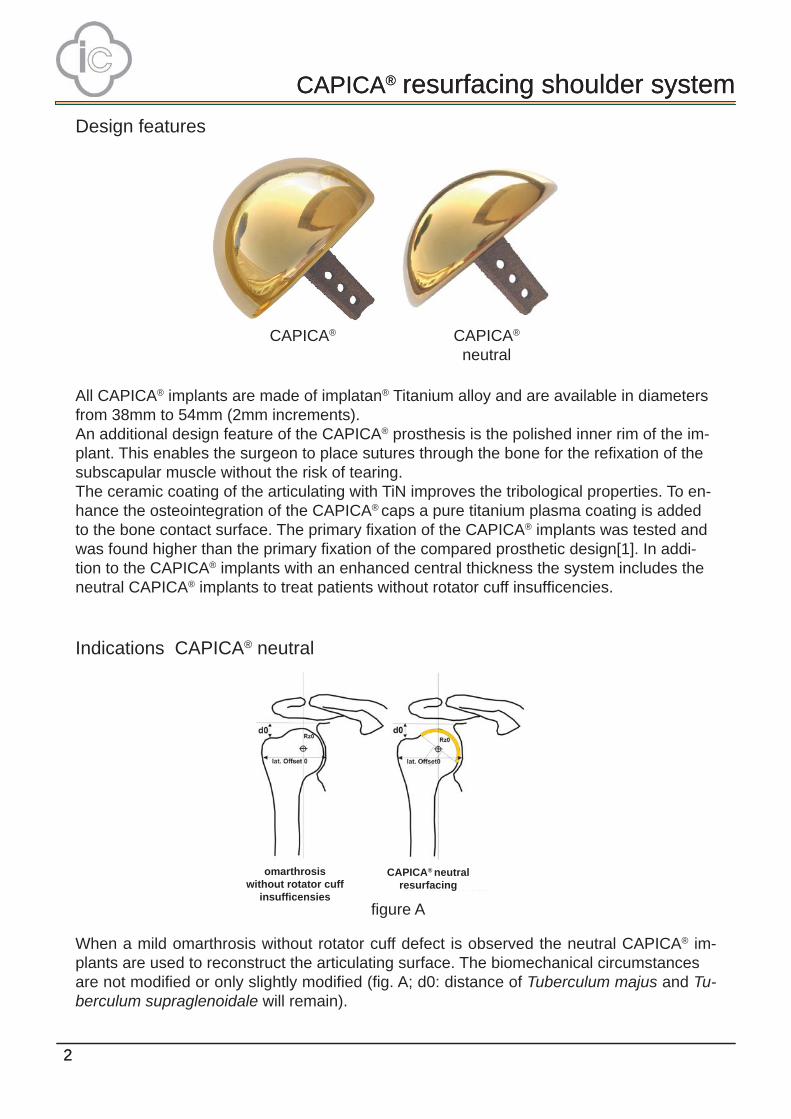
Design features
CAPICA®
neutralCAPICA®
Indications CAPICA® neutral
When a mild omarthrosis without rotator cuff defect is observed the neutral CAPICA® im-plants are used to reconstruct the articulating surface. The biomechanical circumstancesare not modifi ed or only slightly modifi ed (fi g. A; d0: distance of Tuberculum majus and Tu-berculum supraglenoidale will remain).
All CAPICA® implants are made of implatan® Titanium alloy and are available in diametersfrom 38mm to 54mm (2mm increments).An additional design feature of the CAPICA® prosthesis is the polished inner rim of the im-plant. This enables the surgeon to place sutures through the bone for the refi xation of thesubscapular muscle without the risk of tearing. The ceramic coating of the articulating with TiN improves the tribological properties. To en-hance the osteointegration of the CAPICA® caps a pure titanium plasma coating is added to the bone contact surface. The primary fi xation of the CAPICA® implants was tested and was found higher than the primary fi xation of the compared prosthetic design[1]. In addi-tion to the CAPICA® implants with an enhanced central thickness the system includes the neutral CAPICA® implants to treat patients without rotator cuff insuffi cencies.
fi gure A
CAPICA® neutralresurfacing
omarthrosis without rotator cuff
insuffi censies
CAPICA® resurfacing shoulder system
3
CAPICA® resurfacing shoulder system
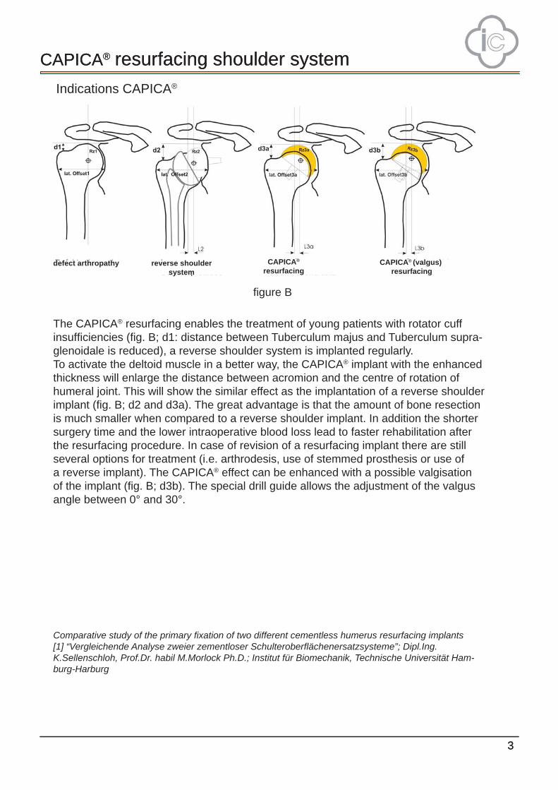
The CAPICA® resurfacing enables the treatment of young patients with rotator cuffinsuffi ciencies (fi g. B; d1: distance between Tuberculum majus and Tuberculum supra-glenoidale is reduced), a reverse shoulder system is implanted regularly.To activate the deltoid muscle in a better way, the CAPICA® implant with the enhancedthickness will enlarge the distance between acromion and the centre of rotation ofhumeral joint. This will show the similar effect as the implantation of a reverse shoulderimplant (fi g. B; d2 and d3a). The great advantage is that the amount of bone resectionis much smaller when compared to a reverse shoulder implant. In addition the shortersurgery time and the lower intraoperative blood loss lead to faster rehabilitation afterthe resurfacing procedure. In case of revision of a resurfacing implant there are stillseveral options for treatment (i.e. arthrodesis, use of stemmed prosthesis or use ofa reverse implant). The CAPICA® effect can be enhanced with a possible valgisationof the implant (fi g. B; d3b). The special drill guide allows the adjustment of the valgusangle between 0° and 30°.
Comparative study of the primary fi xation of two different cementless humerus resurfacing implants[1] “Vergleichende Analyse zweier zementloser Schulteroberfl ächenersatzsysteme”; Dipl.Ing.K.Sellenschloh, Prof.Dr. habil M.Morlock Ph.D.; Institut für Biomechanik, Technische Universität Ham-burg-Harburg
Indications CAPICA®
fi gure B
3
defect arthropathy reverse shouldersystem
CAPICA®
resurfacingCAPICA® (valgus)
resurfacing
CAPICA® resurfacing shoulder system
4
CAPICA® resurfacing shoulder system
4
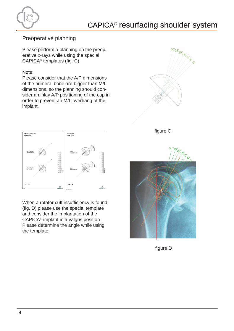
Please perform a planning on the preop-erative x-rays while using the specialCAPICA® templates (fi g. C).
Note:Please consider that the A/P dimensionsof the humeral bone are bigger than M/Ldimensions, so the planning should con-sider an inlay A/P positioning of the cap inorder to prevent an M/L overhang of theimplant.
When a rotator cuff insuffi ciency is found(fi g. D) please use the special templateand consider the implantation of theCAPICA® implant in a valgus positionPlease determine the angle while usingthe template.
Preoperative planning
fi gure C
fi gure D

CAPICA® resurfacing shoulder system
5
CAPICA® resurfacing shoulder system
5
Open the joint in the usual way, using thedeltopektoral or the anterosuperioral ap-proach.Choose the drill guide of the preoperativedetermined size and attach the cannulatedadapter to it. Place the instrument on thearticulating surface of the humerus (fi g. 1b).Align the drill guide parallel to the Collumanatomicum. This will lead to a angle ofabout 125-135°.Optionally you may lock the drill guideto the bone using the short fi xation pins.Therefore please use the pin inserter (fi g.2a).
For implantation of the CAPICA® implantin an outstanding valgus position, pleaseunlock the adapter, adjust the angle andlock the adapter again between 0° and 30°(fi g. 2b).It is recommended to determine the suitablevalgus angle from the preoperative x-rays.Insert the 3,2mm fi xation pin through thecannulated adapter until the mark hasreached the upper end of the sleeve as youcan see on the left (fi g. 3a and 3b).Remove the drill guide, but leave the fi xa-tion pin in the bone.
Surgical technique
fi gure 1a fi gure 1b
fi gure 2a fi gure 2b
fi gure 3a fi gure 3b

CAPICA® resurfacing shoulder system
6
CAPICA® resurfacing shoulder system
6
The fi xation pin is only 120mm long, so a cannulated machine is normally not needed. When you use the ic-adapters while reaming the fi xation pin will stop the reamer order to prevent over reaming.
Mount the surface reamer of the correct size(also refer to the colour coding of the instru-ments) to the ic-adapter and start reamingcarefully.The open design of the reamers allows tocheck the surface during reaming. Make surethat the reamer already rotates before itreaches the bone surface the fi rst time (fi g. and 4b).
When sclerotic bone is presentyou should lease from time to time and clean the reamer.
Note: With increased reamer depth theforces during reaming are also increased.
The open design of the reamers allow thevisual control of the bone chip removal during reaming. Please ream until the reamer has reach the collum and is stopped by the fi xation pin. While using the scale on the impactor (fi g. 5a) you can double check if the reaming is deep enough. Make sure that subchondralebone is reached (fi g. 5b and 5c).
Remove the surface reamer,but leave the fi xation pin in the bone (fi g. 5c).
Add the core reamer to the ic-adapterand ream over the fi xation pin until the reamerstops on the surface (fi g. 6a and 6b).
fi gure 4a fi gure 4b
fi gure 5a
fi gure 6a fi gure 6b
fi gure 5b fi gure 5c
CAPICA® resurfacing shoulder system
7
CAPICA® resurfacing shoulder system
7
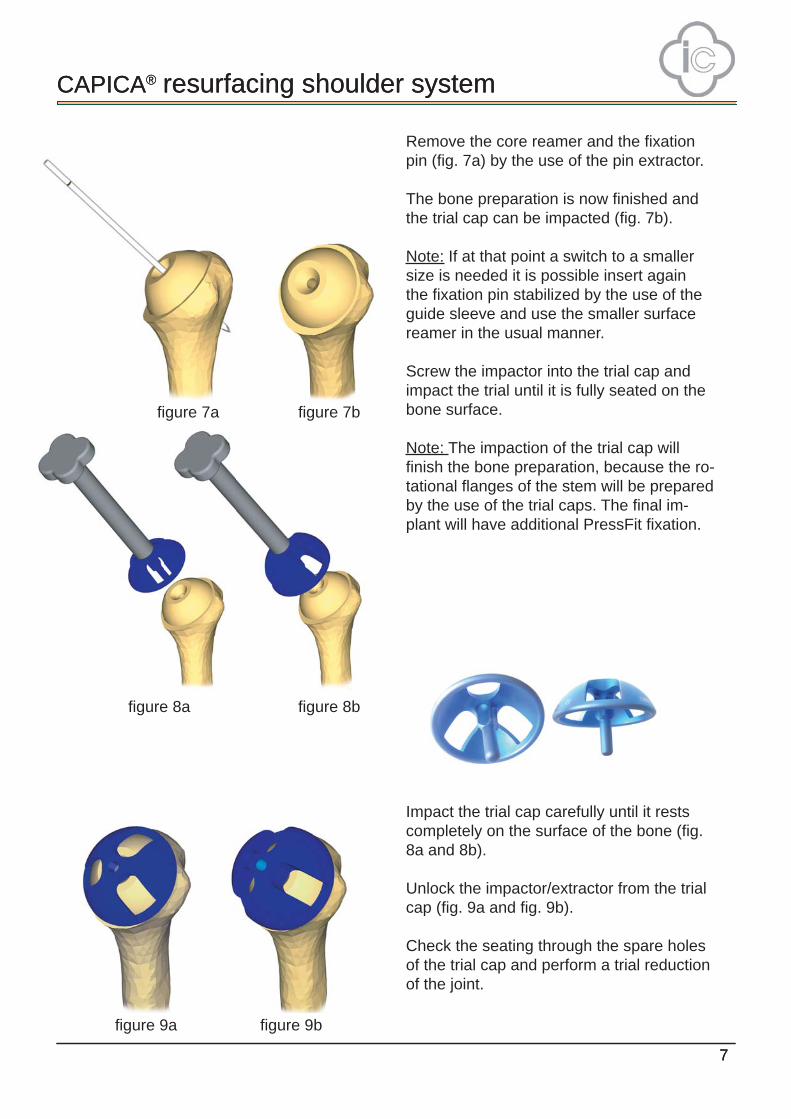
Remove the core reamer and the fi xationpin (fi g. 7a) by the use of the pin extractor.
The bone preparation is now fi nished andthe trial cap can be impacted (fi g. 7b).
Note: If at that point a switch to a smallersize is needed it is possible insert againthe fi xation pin stabilized by the use of theguide sleeve and use the smaller surfacereamer in the usual manner.
Screw the impactor into the trial cap andimpact the trial until it is fully seated on thebone surface.
Note: The impaction of the trial cap will fi nish the bone preparation, because the ro-tational fl anges of the stem will be prepared by the use of the trial caps. The fi nal im-plant will have additional PressFit fi xation.
Impact the trial cap carefully until it restscompletely on the surface of the bone (fi g.8a and 8b).
Unlock the impactor/extractor from the trialcap (fi g. 9a and fi g. 9b).
Check the seating through the spare holesof the trial cap and perform a trial reductionof the joint.
fi gure 7a fi gure 7b
fi gure 8a fi gure 8b
fi gure 9a fi gure 9b

CAPICA® resurfacing shoulder system
8
CAPICA® resurfacing shoulder system
8
After succesful trial reduction you canmount the extractor to the trial cap andremove the trial (fi g. 10a and 10b).
The fi nal implant can now be implanted.The cap is guided by the entry cross of thecentral hole (fi g. 11a).
Insert suture for the fi xation of the sub-scapularis tendon into the bone beforeinserting the implant. The polished innerrim will protect the suture material fromdamage.
Use the impactor to impact the fi nal cap(fi g. 11b).
Make sure that the implant is seated fullyon the bone surface. The gap betweenbone preparation and rim of the cap shouldbe as narrow as possible (fi g. 12a and12b).
fi gure 10b
fi gure 11a
fi gure12a fi gure 12b
fi gure 11b
fi gure 10a

CAPICA® resurfacing shoulder system
9
CAPICA® resurfacing shoulder system
9
Postoperative treatment
wound closure
Close the subscapularis muscle with absorb-able sutures.
Make sure that the rotator cuff is closed com-pletely.
The deltoid muscle should be fi xed to theacromion by the use of absorbable sutures.
postoperative treatment
Passiv mobilisation can be started 48 hourspostoperative and should be considered un-til the fi fth postoperative day.
Active mobilisation in consideration of thepain level should start from the fi fth day until 3 weeks postoperative.
The treatment of the physiotherapist shouldbe performed according to the commonregime of all prosthetic shoulder replace-ments.

1010
CAPICA® resurfacing shoulder system
11
CAPICA® resurfacing shoulder system
11
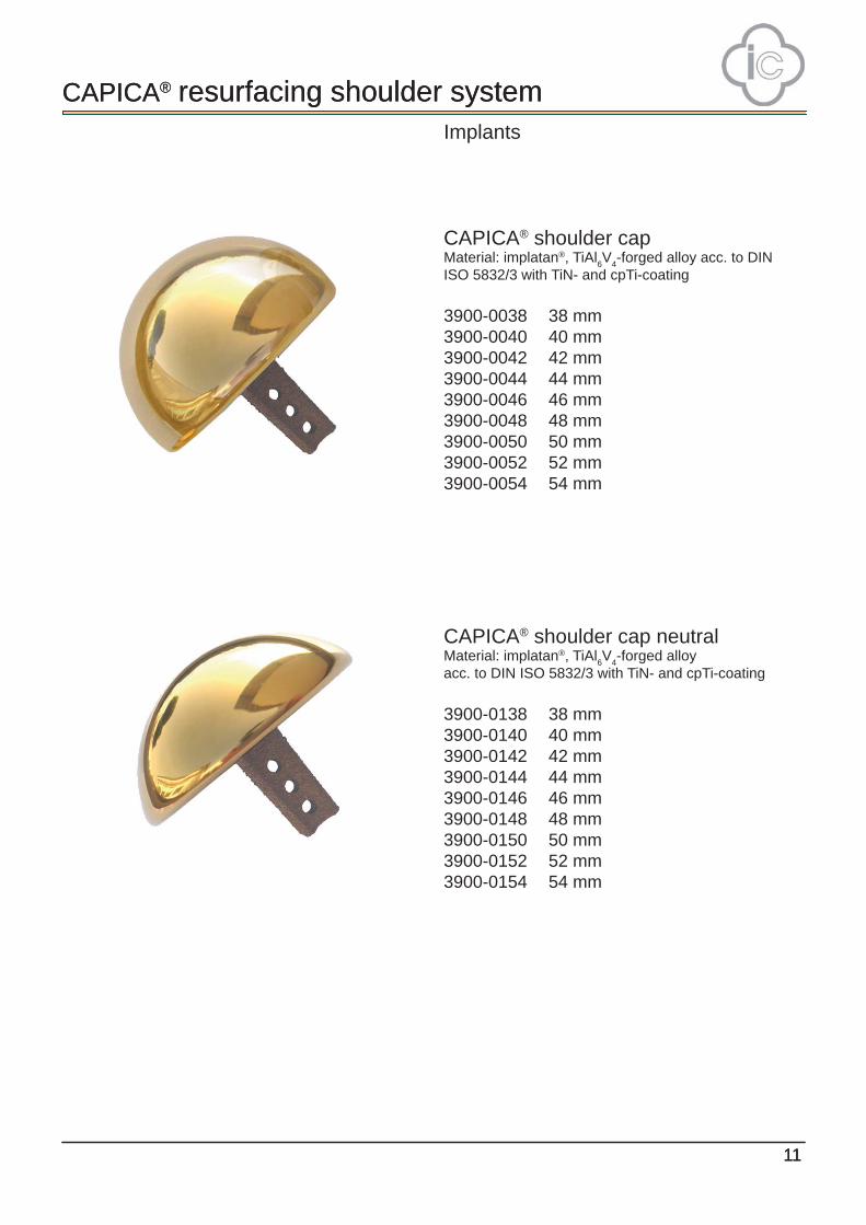
CAPICA® shoulder capMaterial: implatan®, TiAl6V4-forged alloy acc. to DIN ISO 5832/3 with TiN- and cpTi-coating
3900-0038 38 mm3900-0040 40 mm3900-0042 42 mm3900-0044 44 mm3900-0046 46 mm3900-0048 48 mm3900-0050 50 mm3900-0052 52 mm3900-0054 54 mm
CAPICA® shoulder cap neutralMaterial: implatan®, TiAl6V4-forged alloyacc. to DIN ISO 5832/3 with TiN- and cpTi-coating
3900-0138 38 mm3900-0140 40 mm3900-0142 42 mm3900-0144 44 mm3900-0146 46 mm3900-0148 48 mm3900-0150 50 mm3900-0152 52 mm3900-0154 54 mm
Implants
CAPICA® resurfacing shoulder system
12
CAPICA® resurfacing shoulder system
12
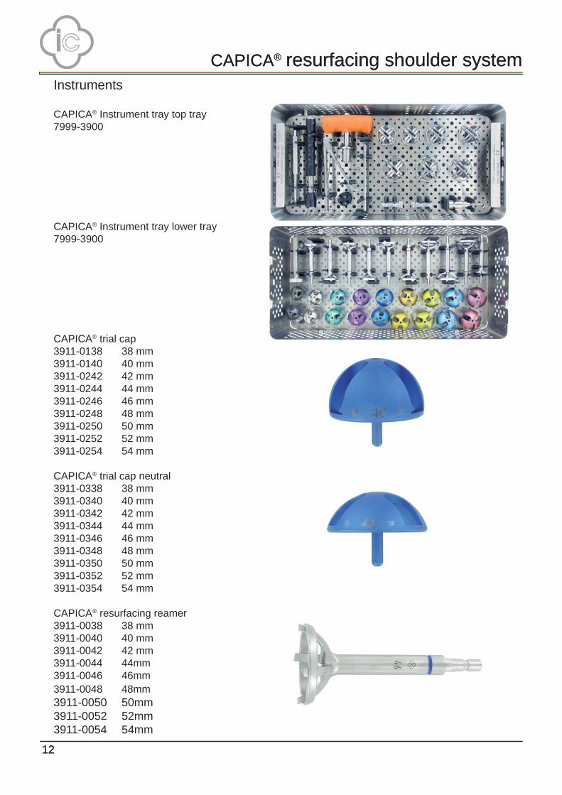
CAPICA® Instrument tray top tray7999-3900
CAPICA® Instrument tray lower tray7999-3900
CAPICA® trial cap3911-0138 38 mm3911-0140 40 mm3911-0242 42 mm3911-0244 44 mm3911-0246 46 mm3911-0248 48 mm3911-0250 50 mm3911-0252 52 mm3911-0254 54 mm
CAPICA® trial cap neutral3911-0338 38 mm3911-0340 40 mm3911-0342 42 mm3911-0344 44 mm3911-0346 46 mm3911-0348 48 mm3911-0350 50 mm3911-0352 52 mm3911-0354 54 mm
CAPICA® resurfacing reamer3911-0038 38 mm3911-0040 40 mm3911-0042 42 mm3911-0044 44mm3911-0046 46mm3911-0048 48mm3911-0050 50mm3911-0052 52mm3911-0054 54mm
Instruments

CAPICA® resurfacing shoulder system
13
CAPICA® resurfacing shoulder system
13
CAPICA® drill guide 3911-0138 38 mm3911-0140 40 mm3911-0142 42 mm3911-0144 44 mm3911-0146 46 mm3911-0148 48 mm3911-0150 50 mm3911-0152 52 mm3911-0154 54 mm
CAPICA® adapter for drill guide3911-0101 (2x)
ic-adapter4223-0022
ic-T-handle4223-0023
pin extractor4223-0007
pin inserter4223-0006
fi xation pins short4223-0029 (4x)
impactor/extractor for trial cap3911-0004
head impactor7512-4444
CAPICA® guide wire 3,2 x 120 mm3911-0000 (2x)
core reamer with stop3911-0001
guide sleeve for resurfacing reamer3911-0002
Instruments
0482
implantcast GmbHLüneburger Schanze 26
D-21614 Buxtehude Germany
phone: +49 4161 744-0 fax: +49 4161 744-200
e-mail: [email protected]: www.implantcast.de
Your local distributor is:
CA
PIC
OP
E-2
7111
1
*+E1
ICCA
PICO
PE++
**+
$$E1
IC27
1111
++*


![Humeral Resurfacing Head - University of Washingtonfaculty.washington.edu/alexbert/Shoulder/Surgery/...head [ Fig. 12 ] and through to the lateral cortex to provide stability. The](https://static.fdocuments.in/doc/165x107/60a585dbb9021c2b170943fa/humeral-resurfacing-head-university-of-head-fig-12-and-through-to-the.jpg)
