SURGICAL TECHNIQUE -...
11
SURGICAL TECHNIQUE TOTAL SHOULDER PROSTHESIS REVERSED CEMENTED AND CEMENTLESS HUMERAL STEM CEMENTLESS GLENOID Orthopaedic Implants www.aston-medical.com REVERSED
Transcript of SURGICAL TECHNIQUE -...
S U R G I C A L T E C H N I Q U E
ToTal
Shoulder
ProSTheSiS
reverSed
cemenTed and cemenTleSS
humeral STem
cemenTleSS glenoid
Orthopaedic Implants
w w w . a s t o n - m e d i c a l . c o m
R E V E R S E D

inTroducTion
Faced with the challenge of performing total shoulder arthroplasty in patients with rotator cuff tear arthropathy, Paul Grammont of Dijon (France) was the first to propose medialisation and lowering of a single, stationary centre of rotation located on the glenoid in 1981.
A team of Dijon researchers and surgeons dared to break with the tradition of exactly reproducing the rotator cuff anatomy. Using comparative anatomy data and applying the emerging concept of functional surgery they conceived a simple, new shape. This led to the development of the first modern reversed shoulder implant that required only deltoid muscle activation – the ‘Trumpet’ prosthesis. The thinking of Paul Grammont and his Dijon colleagues was to create, in essence, a ‘rotator cuff prosthesis’. The kinematics of the prosthesis would overcome the deficient rotator cuff function using only the deltoid muscle.
Always looking to improve on the original design, the Dijon team created the first modular reverse prosthesis, the Delta® (DePuy) in 1991. It is still considered the gold standard by many.
However, with longer follow-up, certain problems emerged.
The main one was scapular notching, which can lead to functional deterioration, polyethylene insert damage and loosening.
To remedy this problem, the prosthesis now has an inferior spherical rim on the glenoid baseplate. This creates a ‘second articulation’ to protect the scapular pillar. It is shaped to improve stability and use the inferior contact surface at the start of movement. The glenoid baseplate is designed to fit various glenoid neck shapes.
Furthermore, this rim improves the implant's primary stability. This ‘second articulation’ lowers the centre of rotation and restores the preload on the deltoid muscle fibres, thereby enhancing the muscle's function.
New ideas have emerged to improve the rotational performance of this type of arthroplasty.
With more than 20 years' follow-up (1st patent filed in 1986), we can safely say that Paul Grammont's theory has been proven.
Prof. Emmanuel BaulotUniversity of DijonFrance
Prof. Pierre TrouilloudUniversity of DijonFrance
And the DUOCENTRIC® team: Dr. Hugues Charles, Dr. Martin Gonzalvez, Prof. Franck Handelberg (Belgium), Prof. Richard Nyffeler (Switzerland).
p. 3 SET UP AND SURGICAL APPROACHES
p. 4 HUMERAL PREPARATION
p. 7 GLENOID PREPARATION
IMPLANTATION OF FINAL GLENOIDp. 9
TRIALSp. 11
IMPLANTATION OF FINAL HUMERAL STEMp. 12
PERSONAL FIT® SURGICAL TECHNIQUEp. 17
TYPICAL CLINICAL CASEp. 16
INSTRUMENTATIONp. 18
3
Patient Positioning
The patient is placed in a semi-seated or beach chair position, with the upper body at the edge of the operating table. The arm is wrapped with sterile drapes and must remain free to move. Full arm adduction and extension are essential for exposing the proximal humerus and inserting the centromedullary stem. An arm or elbow rest is optional. Fig. 1
suPerolateral (sl) aPProach
A skin incision is made in the frontal plane. It starts at the anterior edge of the acromioclavicular joint and extends towards the lateral deltoid. The deltoid is detached from the anterior side of the acromion and divided along its fibres no more than 5 cm distal to the acromion. A longer dissection could damage the axillary nerve and denervate the anterior deltoid. A fixation suture can be placed at the end of the deltoid's split to prevent it from propagating. Adhesions between the deltoid muscle and humeral head are released carefully. If the long head of the biceps tendon is still intact, it is detached from its glenoid insertion and its intra-articular portion is resected. The arm is adducted and extended, and portions of the deltoid are gently retracted to expose the humeral head. Fig. 2
DeltoPectoral (DP) aPProach
The skin incision starts at the lower border of the clavicle near the tip of the coracoid process, and continues along the anterior side of the deltoid muscle to where it inserts on the humeral shaft. The cephalic vein is typically retracted laterally. The conjoined tendon is identified and any adhesions around the humeral head are carefully released. The long head of the biceps is transected and tenodesis performed. The intra-articular stump is resected. The anterior humeral circumflex vessels (three sisters) at the inferior boundary of the subscapularis tendon are coagulated or ligated. The subscapularis tendon and anterior capsule are cut transversely, leaving 5–10 mm of the tendon attached to the lesser tuberosity of the humerus for later repair. The arm is rotated externally and the inferior capsule released from the humeral neck. The deltoid is then retracted, the arm extended and the humeral head dislocated from the glenoid. Fig. 3
SET UP AND SURGICAL APPROACHES
Fig. 1
Fig. 3
CLOSUREPOSTOPERATIVE CARESALVAGE PROCEDURE
p. 14
p. 15 REVISIONCONVERSION OF DUOCENTRIC ANATOMIC OR TRAUMA TO DUOCENTRIC REVERSEDWITHOUT CHANGING HUMERAL STEM
Fig. 2
54
HUMERAL PREPARATION
The numbers in brackets correspond to the various compo-nents of the instrumentation set shown on pp. 18 and 19.
Fig. 4
Fig. 5
5
48
4436 36
35
8
Ulna
Elbow at 90°
SL DP
Fig. 6
48 44
12
36 36
30
35
SL DP
Humeral head
Radius
Fig. 8
34
23
Fig. 7
34
23
SL
22
DP
Fig. 9
125°
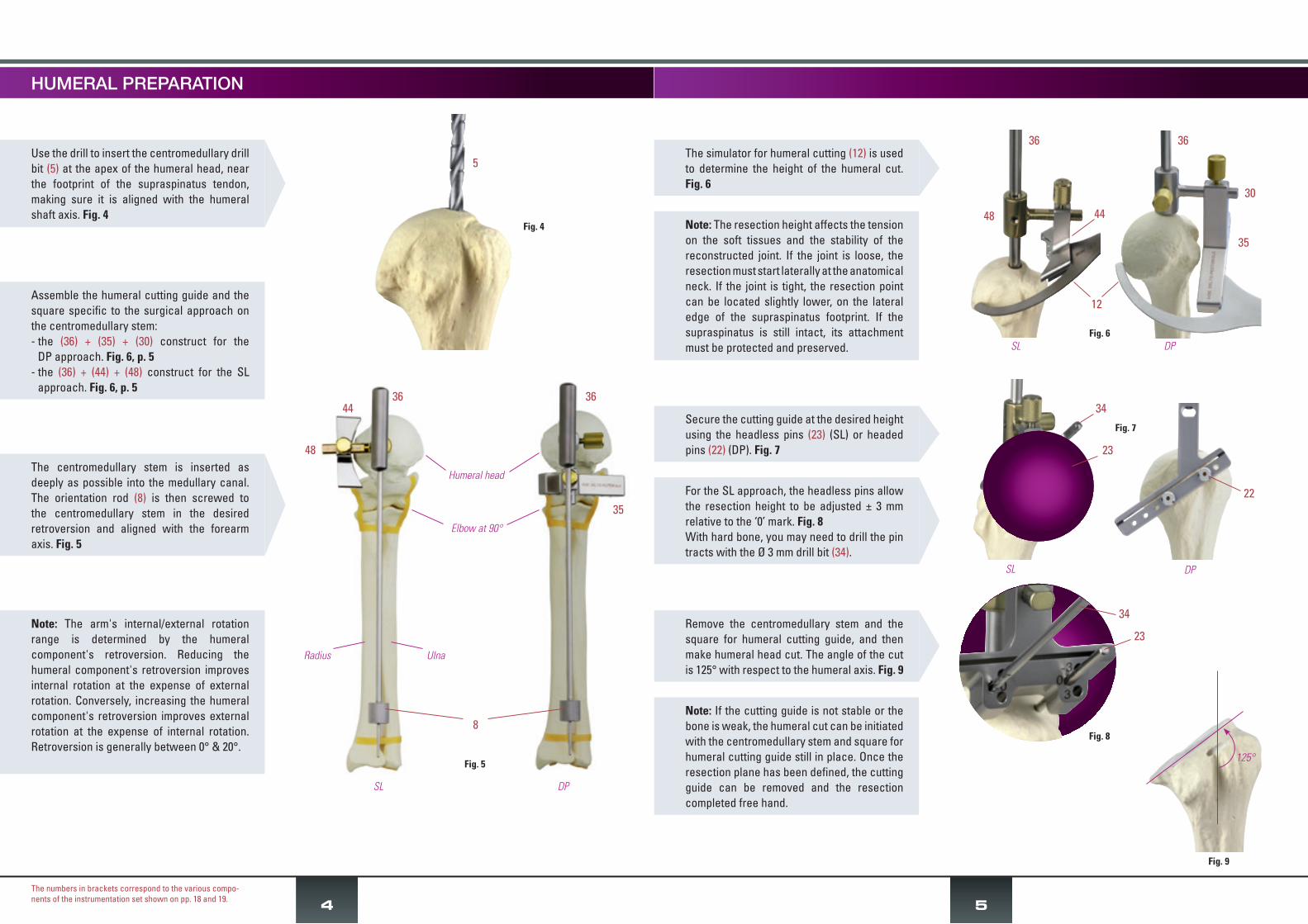
The simulator for humeral cutting (12) is used to determine the height of the humeral cut. Fig. 6
Secure the cutting guide at the desired height using the headless pins (23) (SL) or headed pins (22) (DP). Fig. 7
For the SL approach, the headless pins allow the resection height to be adjusted ± 3 mm relative to the ‘0’ mark. Fig. 8With hard bone, you may need to drill the pin tracts with the Ø 3 mm drill bit (34).
Remove the centromedullary stem and the square for humeral cutting guide, and then make humeral head cut. The angle of the cut is 125° with respect to the humeral axis. Fig. 9
Note: The resection height affects the tension on the soft tissues and the stability of the reconstructed joint. If the joint is loose, the resection must start laterally at the anatomical neck. If the joint is tight, the resection point can be located slightly lower, on the lateral edge of the supraspinatus footprint. If the supraspinatus is still intact, its attachment must be protected and preserved.
Note: If the cutting guide is not stable or the bone is weak, the humeral cut can be initiated with the centromedullary stem and square for humeral cutting guide still in place. Once the resection plane has been defined, the cutting guide can be removed and the resection completed free hand.
Use the drill to insert the centromedullary drill bit (5) at the apex of the humeral head, near the footprint of the supraspinatus tendon, making sure it is aligned with the humeral shaft axis. Fig. 4
Assemble the humeral cutting guide and the square specific to the surgical approach on the centromedullary stem:- the (36) + (35) + (30) construct for the
DP approach. Fig. 6, p. 5- the (36) + (44) + (48) construct for the SL
approach. Fig. 6, p. 5
The centromedullary stem is inserted as deeply as possible into the medullary canal. The orientation rod (8) is then screwed to the centromedullary stem in the desired retroversion and aligned with the forearm axis. Fig. 5
Note: The arm's internal/external rotation range is determined by the humeral component's retroversion. Reducing the humeral component's retroversion improves internal rotation at the expense of external rotation. Conversely, increasing the humeral component's retroversion improves external rotation at the expense of internal rotation. Retroversion is generally between 0° & 20°.
GLENOID PREPARATIONHUMERAL PREPARATION
Fig. 16
Fig. 14
32 or 46
9
6
Fig. 15
3
76
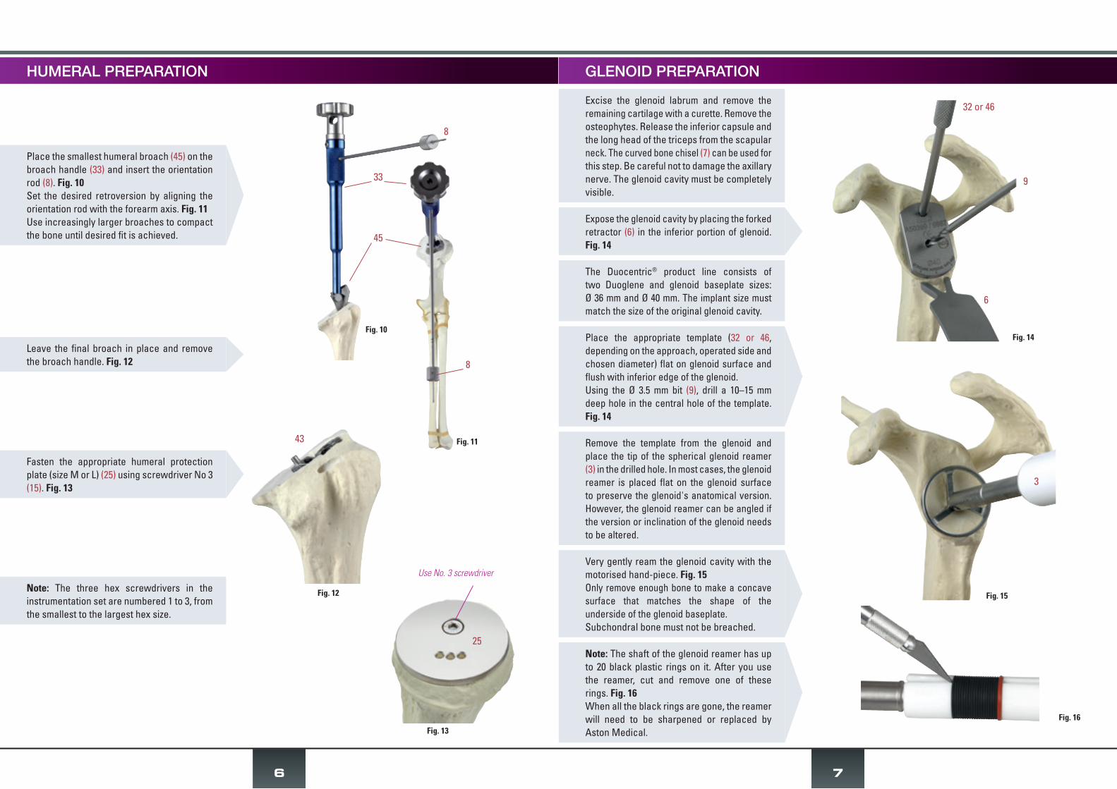
Note: The three hex screwdrivers in the instrumentation set are numbered 1 to 3, from the smallest to the largest hex size.
Fig. 10
Fig. 11
8
33
45
8
Fig. 13
25
Use No. 3 screwdriver
Fasten the appropriate humeral protection plate (size M or L) (25) using screwdriver No 3 (15). Fig. 13
Leave the final broach in place and remove the broach handle. Fig. 12
Place the smallest humeral broach (45) on the broach handle (33) and insert the orientation rod (8). Fig. 10Set the desired retroversion by aligning the orientation rod with the forearm axis. Fig. 11Use increasingly larger broaches to compact the bone until desired fit is achieved.
Fig. 12
Excise the glenoid labrum and remove the remaining cartilage with a curette. Remove the osteophytes. Release the inferior capsule and the long head of the triceps from the scapular neck. The curved bone chisel (7) can be used for this step. Be careful not to damage the axillary nerve. The glenoid cavity must be completely visible.
Expose the glenoid cavity by placing the forked retractor (6) in the inferior portion of glenoid. Fig. 14
The Duocentric® product line consists of two Duoglene and glenoid baseplate sizes: Ø 36 mm and Ø 40 mm. The implant size must match the size of the original glenoid cavity.
Place the appropriate template (32 or 46, depending on the approach, operated side and chosen diameter) flat on glenoid surface and flush with inferior edge of the glenoid. Using the Ø 3.5 mm bit (9), drill a 10–15 mm deep hole in the central hole of the template. Fig. 14
Remove the template from the glenoid and place the tip of the spherical glenoid reamer (3) in the drilled hole. In most cases, the glenoid reamer is placed flat on the glenoid surface to preserve the glenoid's anatomical version. However, the glenoid reamer can be angled if the version or inclination of the glenoid needs to be altered.
43
Very gently ream the glenoid cavity with the motorised hand-piece. Fig. 15 Only remove enough bone to make a concave surface that matches the shape of the underside of the glenoid baseplate. Subchondral bone must not be breached.
Note: The shaft of the glenoid reamer has up to 20 black plastic rings on it. After you use the reamer, cut and remove one of these rings. Fig. 16When all the black rings are gone, the reamer will need to be sharpened or replaced by Aston Medical.

IMPLANTATION OF FINAL GLENOID
9
Fig. 19
31 or 47
39
Fig. 21
31 or 47
5
Fig. 20
31 or 47
42
8
Note: In most cases, the glenoid baseplate with 20 mm peg is sufficient. If the glenoid bone is osteoporotic, the bone stock is inadequate or this is a revision procedure, it is best to use the glenoid baseplate with 40 mm peg. In these cases, a hole should be made in the medial cortex to increase the implant's stability. The 40 mm peg can be shortened to 30 mm if needed. Use bolt cutters (not supplied).
With the pin forceps (10), place the Ø3/Ø6 shouldered pin for glenoid centring (42) in the central hole. Fig. 17
Set the glenoid inferior cutting template (31 or 47, depending on the approach, operated side and chosen diameter) on the shouldered pin. Fig. 18
Forcefully strike the impactor (39) on the template, particularly its lower part, until the head of the pin sticks out. Figs. 19, 20
Remove pin (42) with the forceps (10) and drill the hole for the glenoid baseplate peg with the step drill (5) of the chosen length. Fig. 21
GLENOID PREPARATION
To optimise the size and positioning of Duocentric® Reversed implants, Aston Medical offers the Personal Fit® PSI (patient-specific instruments) (see DOC2661). This system allows the surgeon to plan the procedure pre-operatively based on the patient's CT images. The humeral and glenoid templates prepared based on the preoperative plan will be used to reproduce the planned implant position intra-operatively (see Personal Fit® surgical technique on page 17).
Fig. 18
31 or 47
Screw the glenoid baseplate impactor (4) into the chosen glenoid baseplate. Insert the baseplate peg in the peg hole. Orient the implant so its inferior edge is aligned with the glenoid's inferior edge. Fig. 22
Use light hammer taps to impact the implant. Unscrew glenoid baseplate impactor and make sure the baseplate is solidly anchored in the glenoid.
The glenoid baseplate will be secured with three screws. In most cases, the Ø 4.2 mm screws are sufficient. Cancellous bone screws (Ø 5 mm) are also available.
Bicortical purchase of the screws is recommended for optimal glenoid implant hold.
The superior screw can be angled upwards 15° into the base of the coracoid process. Make sure not to damage the suprascapular nerve at the medial base of the coracoid.
Because of the funnel shape of the scapular neck, the two inferior screws must converge to ensure adequate screw purchase. They must be in different horizontal planes to prevent their tips from touching. The anterior screw can be angled slightly up and the posterior screw slightly down, towards the scapular pillar.
Fig. 22
4
Fig. 17
42
TRIALS
Fig. 25
Fig. 27
38 or 40
Fig. 26
41
37
43
11
Use No.3 screwdriver
Fig. 23
Fig. 24
1
34 or 9
20
10
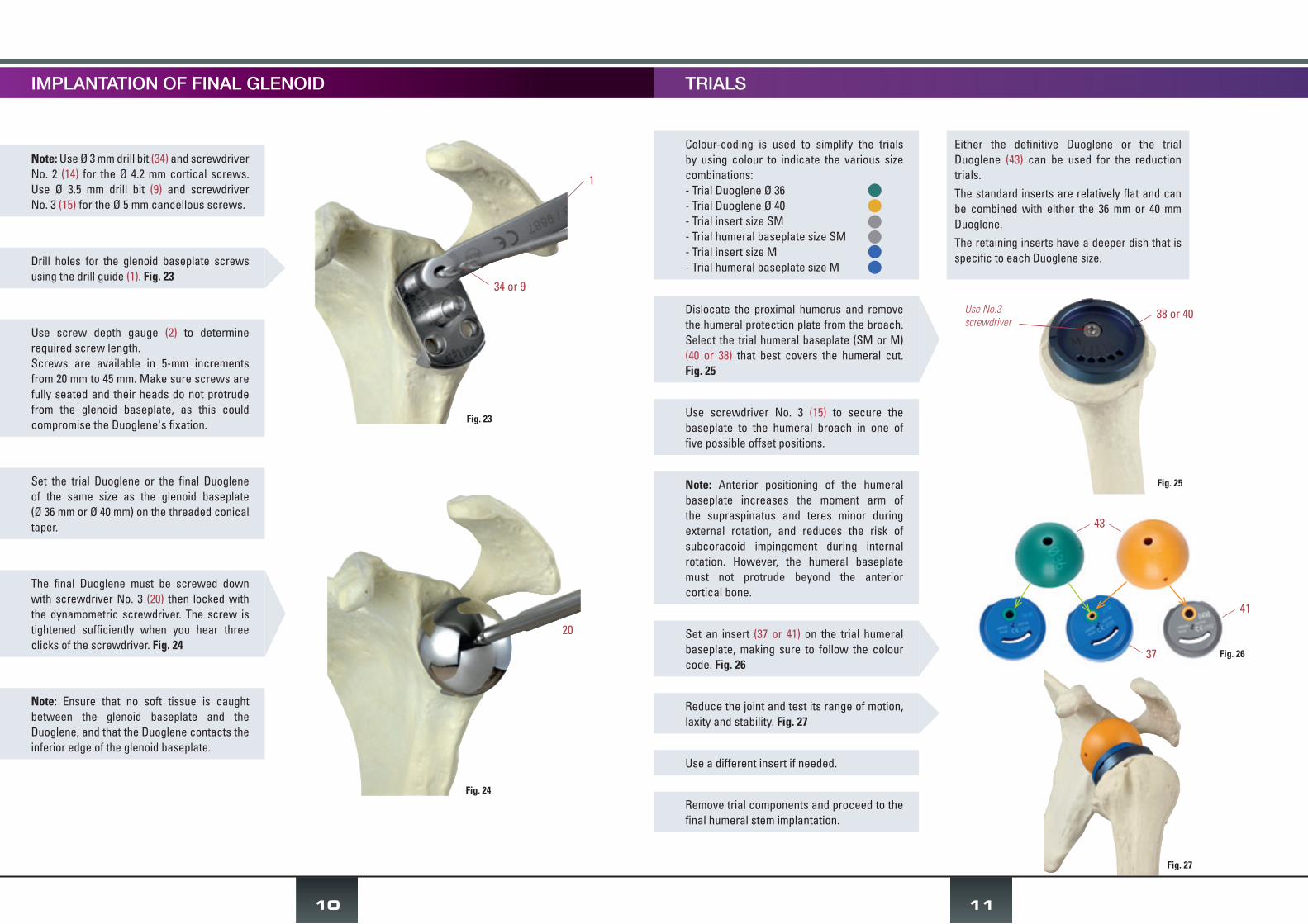
Note: Use Ø 3 mm drill bit (34) and screwdriver No. 2 (14) for the Ø 4.2 mm cortical screws. Use Ø 3.5 mm drill bit (9) and screwdriver No. 3 (15) for the Ø 5 mm cancellous screws.
Use screw depth gauge (2) to determine required screw length.Screws are available in 5-mm increments from 20 mm to 45 mm. Make sure screws are fully seated and their heads do not protrude from the glenoid baseplate, as this could compromise the Duoglene's fixation.
Set the trial Duoglene or the final Duoglene of the same size as the glenoid baseplate (Ø 36 mm or Ø 40 mm) on the threaded conical taper.
Note: Ensure that no soft tissue is caught between the glenoid baseplate and the Duoglene, and that the Duoglene contacts the inferior edge of the glenoid baseplate.
Drill holes for the glenoid baseplate screws using the drill guide (1). Fig. 23
The final Duoglene must be screwed down with screwdriver No. 3 (20) then locked with the dynamometric screwdriver. The screw is tightened sufficiently when you hear three clicks of the screwdriver. Fig. 24
IMPLANTATION OF FINAL GLENOID
Colour-coding is used to simplify the trials by using colour to indicate the various size combinations:- Trial Duoglene Ø 36- Trial Duoglene Ø 40- Trial insert size SM- Trial humeral baseplate size SM- Trial insert size M- Trial humeral baseplate size M
Either the definitive Duoglene or the trial Duoglene (43) can be used for the reduction trials.The standard inserts are relatively flat and can be combined with either the 36 mm or 40 mm Duoglene. The retaining inserts have a deeper dish that is specific to each Duoglene size.
Dislocate the proximal humerus and remove the humeral protection plate from the broach. Select the trial humeral baseplate (SM or M) (40 or 38) that best covers the humeral cut. Fig. 25
Use screwdriver No. 3 (15) to secure the baseplate to the humeral broach in one of five possible offset positions.
Note: Anterior positioning of the humeral baseplate increases the moment arm of the supraspinatus and teres minor during external rotation, and reduces the risk of subcoracoid impingement during internal rotation. However, the humeral baseplate must not protrude beyond the anterior cortical bone.
Use a different insert if needed.
Remove trial components and proceed to the final humeral stem implantation.
Set an insert (37 or 41) on the trial humeral baseplate, making sure to follow the colour code. Fig. 26
Reduce the joint and test its range of motion, laxity and stability. Fig. 27

13
If using a cemented humeral stem, make sure the press-fit is adequate to allow immediate joint reduction without having to wait for the cement to set completely.
Clean and reduce the joint.
Insert the final prosthesis into the medullary canal using the humeral impactor tip (16) and impaction handle (19), making sure to maintain the retroversion. Fig. 34
If the greater tuberosity hits the acromion during abduction, tuberoplasty can be performed. However, make sure that the infraspinatus attachment is not altered.
You may want to record the intraoperative range of motion.
Check the joint's mobility and stability. Fig. 35
Fig. 35
Fig. 34
19
16
IMPLANTATION OF FINAL HUMERAL STEM
Fig. 33
12
Note: The insert can also be joined with the humeral baseplate once it is implanted in the patient using the insert impactor tip and impaction handle (19). Since this manoeuvre requires powerful hammer strikes, it is strongly recommended to assemble the components on the table before inserting the prosthesis in the humeral canal.
On the instrument table, place the impaction base (26) on the press structure (27) so that the size of the selected baseplate is visible. Fig. 28
Place the final humeral baseplate on the impaction base (26), with the Morse taper facing up, and set the selected humeral stem in the predetermined offset position. Fig. 29
Remove prosthesis from impaction base and tighten binding screw supplied with humeral baseplate using screwdriver No. 1. Fig. 31
Place the white part of the sliding piston impactor (28) on the outer portion of the humeral stem and impact the components together by striking the piston with a hammer. Fig. 30
Set all components back on the impaction base and strike the piston with the hammer again to finalise the taper fixation.
Fully tighten the binding screw with the Allen wrench (21).
Position the final polyethylene insert on the humeral baseplate by placing the insert's large superior slot under the baseplate's metal lip - Fig. 32 - then clip the insert into place by firmly pressing the stem down against the table. Fig. 33
Fig. 28
Fig. 29
Fig. 32
Baseplate size27
27
26
26
26
Fig. 31
Use screwdriver No. 1 or Allen wrench
Fig. 30
28

For the superolateral approach, the anterior deltoid must be reattached to the acromion with non-absorbable transosseous sutures.For the deltopectoral approach, reattaching the subscapularis tendon will improve the shoulder's stability and internal rotation. One or two suction drains can be used to drain the wound.Close the wound layer by layer.
CLOSURE
POSTOPERATIVE CARE
The reinserted anterior deltoid muscle and the reattached subscapularis tendon must be protected for 6–12 weeks. This makes it necessary to immobilize the arm. Gentle passive motion exercises can be initiated once the drains are removed. Extreme movements must be avoided to reduce the risk of dislocation and rupture of the reattached structures. Active motion can be resumed after 6 weeks. Strengthening exercises are typically not needed and should not be performed within the first 3 months postoperative.
SALVAGE PROCEDURE
If it is impossible to secure the glenoid component, a Ø 50-mm prosthetic head (item 30501940) is available for a hemiarthroplasty procedure.
14
Fig. 37
Fig. 38
Fig. 39
The Ø 50 mm head can be attached to the humeral stem in two different medial offset positions and five different posterior offset positions – Fig. 36 – to provide optimal coverage of the humeral cut.
The humeral head is then placed on the stem by inserting:- the Ø 50 mm head's taper into the recess on
the stem- the stem's peg in one of the five holes used
to adjust the posterior offset. Fig. 38
The Morse taper supplied with the humeral head is placed in the most suitable medial offset hole and locked into position with screwdriver No. 3. Fig. 37
The prosthetic head must be impacted into position with the head impactor tip (24) assembled with the impaction handle (19). Fig. 39
Medial offset
Morse taper
Posterior offsetFig. 36
24
19
1) APPROACH
It is recommended that revision surgery be performed using the deltopectoral approach, which allows the distal incision to be extended without damaging the axillary nerve. Release any adhesions between the proximal humerus and the underlying surface of the deltoid muscle and conjoined tendon. If the subscapularis is still intact, detach its tendon and then release the inferior joint capsule. The axillary nerve must be protected. Lastly, dislocate the joint.
2) IMPLANT EXTRACTION
A basket with extraction instruments (A50324) is required for the revision procedure and is available upon request.
Removal of humeral prosthesis:Detach the polyethylene insert from the humeral baseplate, using either the insert extractor (29) or a pair of scissors.Unscrew the humeral baseplate using the 2 mm Allen wrench (21 or 49).Separate the baseplate from the humeral stem by tapping around it with a metal instrument.Remove the humeral stem using the extraction rod (50) assembled with the slap hammer (55) and the reversed stem disimpaction tip (52).If the stem is fixed solidly in the humeral canal, a transhumeral approach with a pectoralis major-pedicled bone window that preserves its bone insertion (Gohlke's technique) can be used.
Removal of glenoid implant:Use screwdriver No. 3 (15) to loosen the Duoglene from the glenoid baseplate.Remove the screws from the baseplate using either screwdriver No. 2 or 3 (14 or 15).Screw the glenoid baseplate disimpactor tip (53) into the glenoid baseplate and extraction rod (50) assembled with the slap hammer (55). Release the adhesions between the implant and bone using quick rotational movements.
Note: If extracting a 1st generation glenoid baseplate with expandable peg, use the specially designed extraction tip (54) that screws into the expandable peg's recess in the middle of the baseplate.
REVISION
- Extract the Anatomical or Trauma head by tapping on its periphery with an instrument (e.g. bone tamp) to release the Morse taper.
- Continue with the revision procedure described above while using the right or left trial conversion baseplate M (item A50250 or A50251 by request) which makes up the angle between the initial 140° cut and the 125° angle of the humeral baseplate for the Duocentric® reverse shoulder prosthesis.
- Use the corresponding final implant (item 30141210 or 30141230).
CONVERSION OF DUOCENTRIC ANATOMIC OR TRAUMA TO DUOCENTRIC REVERSED WITHOUT CHANGING THE HUMERAL STEMTHIS OPTION REQUIRES A SET OF TRIAL AND IMPLANTABLE HUMERAL BASEPLATES THAT MUST BE PRE-ORDERED
15
16
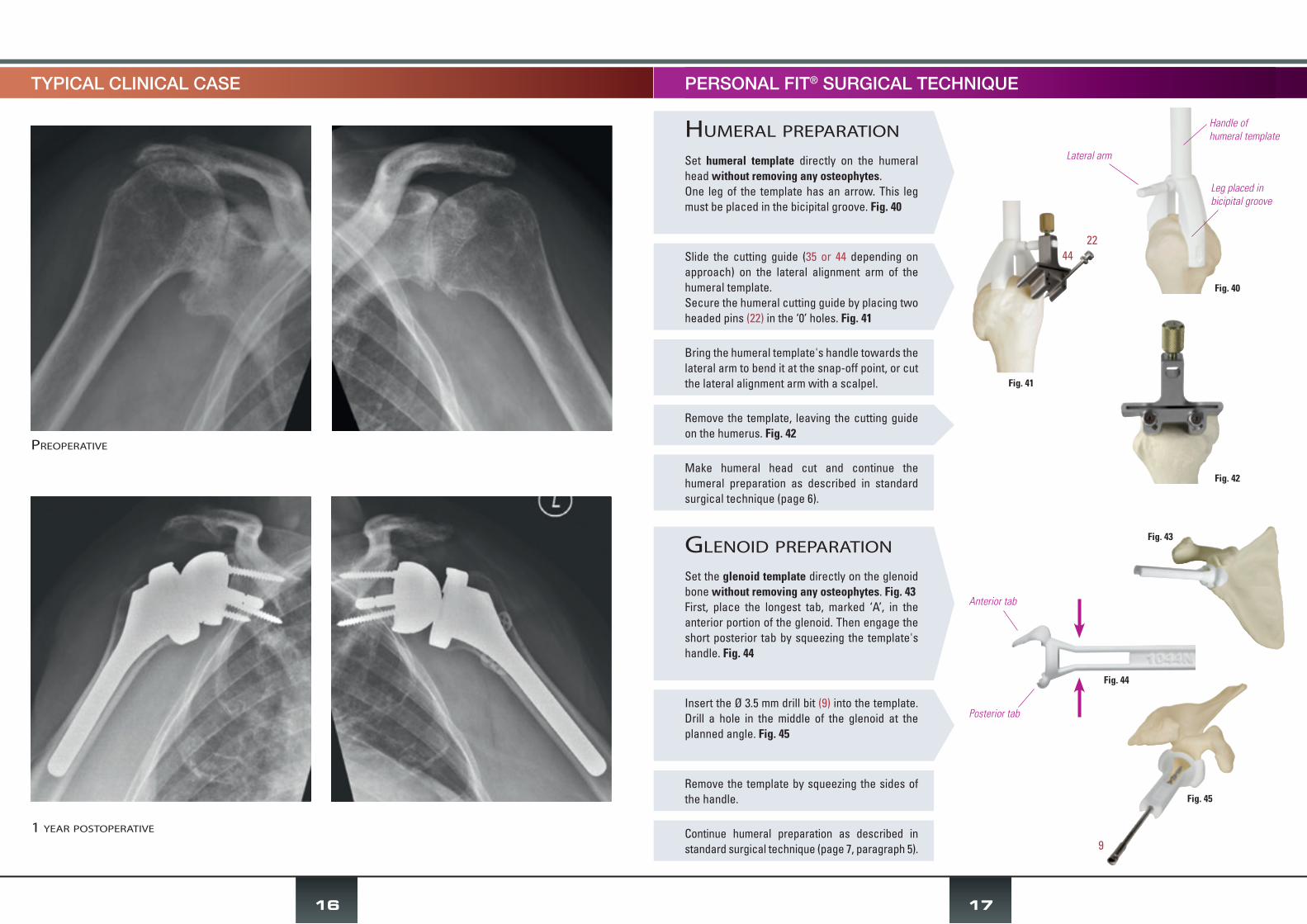
TYPICAL CLINICAL CASE
PreoPerative
1 year PostoPerative
17
Bring the humeral template's handle towards the lateral arm to bend it at the snap-off point, or cut the lateral alignment arm with a scalpel.
Make humeral head cut and continue the humeral preparation as described in standard surgical technique (page 6).
Remove the template by squeezing the sides of the handle.
Continue humeral preparation as described in standard surgical technique (page 7, paragraph 5).
humeral PreParation
Set humeral template directly on the humeral head without removing any osteophytes.One leg of the template has an arrow. This leg must be placed in the bicipital groove. Fig. 40
Slide the cutting guide (35 or 44 depending on approach) on the lateral alignment arm of the humeral template.Secure the humeral cutting guide by placing two headed pins (22) in the ‘0’ holes. Fig. 41
Remove the template, leaving the cutting guide on the humerus. Fig. 42
glenoiD PreParation
Set the glenoid template directly on the glenoid bone without removing any osteophytes. Fig. 43First, place the longest tab, marked ‘A’, in the anterior portion of the glenoid. Then engage the short posterior tab by squeezing the template's handle. Fig. 44
Insert the Ø 3.5 mm drill bit (9) into the template. Drill a hole in the middle of the glenoid at the planned angle. Fig. 45
PERSONAL FIT® SURGICAL TECHNIQUE
Fig. 40
Fig. 41
Fig. 42
Handle ofhumeral template
Leg placed in bicipital groove
Lateral arm
Fig. 43
Fig. 45
4422
9
Anterior tab
Posterior tab
Fig. 44

1: drill guide (A33553)
2: screw depth gauge (A34453)
3: glenoid reamer (A50266)
4: glenoid baseplate impactor (A50454)
5: step drill bit Ø 5.5 and Ø 8 mm for centromedullary and peg drilling (A650170)
6: forked retractor (A50216)
7: curved bone chisel (A50158)
8: orientation rod (A50328)
9: Ø 3.5 mm drill bit L 195 mm (A50175)
10: pin forceps (A33668)
11: forceps for trial Duoglene (A50432)
core basket
12: simulator for humeral cutting (A50117)
13: Hex screwdriver No. 1 (A50184)
14: Hex screwdriver No. 2 (314070)
15: Hex screwdriver No. 3 (SA105)
16: humeral impactor tip (A50191)
17: Ø 32 mm ball insert impactor tip (A50220)
18: insert impactor tip (A50105)
19: impaction handle (A50099)
20: 3.5 mm dynamometric screwdriver (A324052)
21: 2 mm hex. Allen wrench (A50421)
22: headed pins (A32192)
23: headless pins (A06912)
24: bail out head impactor tip (A50102)
25: humeral protection plates (A650129,
A650130)
26: humeral baseplate impaction base
(A650161)
27: press structure (A650167)
28: sliding piston impactor (A650166)
29: insert extractor (A30060)
inSTrumenTaTion
a650172 bottom
a650172 toP
2
14
3
4
13
5
15
7
21
23
22
8
9
10
20
29
28
27
2426
19
11
1
12
6
16
17
18
18
25
30: square for humeral cutting guide for
deltopectoral approach (A50114)
31: glenoid inferior cutting templates - DP approach (A50360 to A50363)
32: glenoid templates - DP approach
(A50401, A50400, A50354, A50355)
33: broach handle (A50339, A50452, A50325)
34: Ø 3 mm drill bit (A50214)
35: humeral cutting guide for DP approach (A50116)
36: centromedullary stem (A50453)
suPerolateral anD DeltoPectoral aPProach basket
extraction basket (by request)
37: trial inserts M (A50258, A50259, A50230, A50231, A50063, A50058, A50059)
38: trial humeral baseplates M (A50470,
A50257)
39: black impactor (A50403)
40: trial humeral baseplates SM (A50382,
A50468)
41: trial inserts SM (A50383 to A50389)
42: shouldered pins (A50420)
43: trial Duoglenes (A50474 ; A50475)
44: humeral cutting guide for SL approach (A50248)
45: humeral broaches (A50068, A50069,
A50070 and A650071)
46: glenoid templates - superior approach (A50399, A50364)
47: glenoid inferior cutting templates superior approach (A50370 ; A50369)
48: square for humeral cutting guide for superior approach (A50249)
a50482 bottom
a50482 toP
49: 2-mm hex. Allen wrench (A50421)
50: extraction rod (A50579)
51: anatomical stem disimpaction tip (A50574)
52: reversed stem disimpaction tip (A50575)
53: glenoid baseplate disimpactor tip (A50581)
54: glenoid baseplate disimpaction tip (expandable peg) (A50582)
55: slap hammer (A50577)
31
32
33
34
35
36
3033
38
39
40
41
4445
46
46
47
47
37
42
43
48
a50324
19
- 1 -
- 2 -
- 3 -
54
50
49
55
515253

I N V E R S É E
®
*DOC
2786
*
Orthopaedic Implants
Aston Medical - France - Phone 33 (0)4 77 93 00 04 - Fax 33 (0)4 77 74 35 93Z.I. Montreynaud - 19 rue V. Grignard - 42000 Saint-Etienne
This document has no contractual value as the manufacturer reserves the right to make changes to improve the quality of the product without prior notice.
For further information, refer to the product documentation and the instructions for use. This surgical technique is not valid for the United States market.
INDICATIONSTotal shoulder prosthesis for glenohumeral osteoarthritis (OA), revision arthroplasty with deficient rotator cuff, pseudoparalysis, complex fracture (3 or more fragments) of humeral head in elderly patient.
PRINCIPLES• Lowering and medialisation of the joint's centre of rotation• Extension of adduction range of motion due to resurfacing of scapular pillar• Option to convert fracture stem to reverse prosthesis without changing the stem
FEATURESThe DUOCENTRIC® product line integrates the biomechanical concepts of a reverse shoulder arthroplasty:
• Humeral stem (cemented or cementless) is available in 4 standard sizes and 2 revision sizes:- requires 125° humeral cut relative to humeral shaft axis- has a minimally invasive intramedullary shape with T-shaped cross-section and lateral fins. The lateral portion of the cemented
model has holes for tuberosity fixation for complex fracture cases• Humeral baseplate available in 2 sizes and 4 heights:
- accepts humeral insert- has 5 possible settings for anteroposterior offset- makes it possible to convert 140° cut with a fracture stem to a 125° cut required for reverse prosthesis (special model, must
be requested)• Humeral insert available as standard model (3 thicknesses) or retaining model (2 thicknesses):
- secured to baseplate through lip and antirotation lug- allows humerus height and lateralisation to be adjusted
• Duoglene in 36 mm or 40 mm diameter:- hemispheric- secured to glenoid baseplate with combination screw and Morse taper system
• Glenoid baseplate (cementless) is available in 2 sizes that match the Duoglene sizes:- anchored in bone through a snap-off peg available in different lengths, 3 screws and dual surface coating- spherical rim extends the shoulder's adduction range before the insert makes contact with the scapular pillar- positioned in the inferior portion of the glenoid using implantation guides
The instrumentation set can be used for either the deltopectoral or anterolateral approach.The Personal Fit® system, CT scan-based 3D planning software and patient-specific templates, is available for the Duocentric® Expert Reversed prosthesis.
MATERIALS• Stainless steel (ISO 5832-9) for the stem, baseplate, Duoglene and glenoid baseplate• Ultra-high molecular weight polyethylene (ISO 5834-1 and ISO 5834-2) for the humeral insert• Stainless steel (ISO 5832-9) for the Ø 5 mm and Ø 4.2 mm screws• Hydroxyapatite coating on stem; dual coating of pure titanium and hydroxyapatite on glenoid baseplate
(per manufacturer's specifications and applicable standards)
IMPLANT ITEM CODES
�ITEM CODES FOR INSTRUMENTATION SETSCore basket A650172 ; Basket for superolateral and deltopectoral approaches A50482 Extraction basket (by request) A50324
HUMERAL INSERT Size SM Size M
Standard4 mm 30136140 301400409 mm 30236140 3024004012 mm 30336140 30340040
For Ø 36 For Ø 40 For Ø 36 For Ø 40
Retaining4 mm 30536040 30540040 30436040 304400409 mm 30536940 30540940 30436940 30440940
GLENOID Ø 36 mm Ø 40 mmDuoglene 30236020 30240020
Baseplate snap-off peg 20 mm 30192924 30292924Baseplate snap-off peg 40 mm 30194924 30294924
STERILE SCREW Ø 5 mm Ø 4.2 mmL 20 mm 83502041 76042041L 25 mm 83502541 76042541L 30 mm 83503041 76043041L 35 mm 83503541 76043541L 40 mm 83504041 76044041L 45 mm 83504541 76044541
REVERSED HUMERAL STEM Cementless CementedSize 1 - 110 mm 30112594 30112584Size 2 - 120 mm 30212594 30212584
Size 2.5 - 125 mm 30252594 30252584Size 3 - 130 mm 30312594 30312584Size 1 - 160 mm - 30116584Size 2 - 170 mm - 30217584
HUMERAL BASEPLATE Size SM Size MStandard 0 mm 30300040 30200040
Standard +5 mm 30305040 30205040Standard +10 mm* 30310040* 30210040*Standard +20 mm* 30320040* 30220040*
125°/140°*Left* 30141210*
Right* 30141230** by request ** used if glenoid prosthesis cannot be implanted
SALVAGE IMPLANTRemovable taper 30796041
Diaphyseal locking screw (standard baseplate) 30451141Diaphyseal locking screw (raised baseplate) 30451341
Anatomical head Ø 50 mm / H 19 mm** 30501940**
ce
103
-201
7
Notified body
0120
R E V E R S E D