Surge Protective Devices (SPD)...UL 1449 I-nominal rating 20kA UL 1449 short circuit current rating...
18
Siemens Industry, Inc. SPEEDFAX™ 2017 Product Catalog 10-1 10 SPD Integrally Mounted SPDs External or Wall Mounted SPDs Residential SPDs Features n Per Phase Surge Current Capacity ranging from 100 kA to 1000 kA n Industry best VPRs n I n = 20 kA (most models) n Across the board UL 96A compliance (most models) n Ground Reference Monitoring (GRM) diagnostics Features n Per Phase Surge Current Capacity ranging from 50 kA to 1000 kA n Industry best VPRs n I n = 20 kA (most models) n Across the board UL 96A compliance (most models) n Ground Reference Monitoring (GRM) diagnostics (excluding TPS3 03 & TPS3 09) Features n Per Phase Surge Current Capacity of 40, 50, 60, 100 or 140 kA n Complete Service Protection for - Power - Telephone - Coax n Ground Reference Monitoring (GRM) diagnostics See pages 1-50 – 1-52 contents Siemens TPS3 family of hardwired Surge Protective Devices (formally known as Surge/Lightning Arrestors and/or Transient Voltage Surge Suppressors –TVSS) Family SPDs 10-2 SOLID Protection 10-3 BoltShield™ Surge Protective Devices 10-4 – 10-5 First Surge 10-6 – 10-7 TPS3 01 and TPS3 L1 (10 Mode) 10-8 TPS3 02 and TPS3 L2 (10 Mode) 10-9 TPS3 03 10-10 TPS3 03 DC 10-11 TPS3 05 and TPS3 L5 (10 Mode) 10-12 TPS3 06 and TPS3 L6 (10 Mode) 10-13 TPS3 09 10-14 TPS3 11 10-15 TPS3 12 and TPS3 L12 (10 mode) 10-16 TPS3 15 and TPS3 L15 (10 mode) 10-17 Frequently Asked Questions 10-18 Scan to connect online to the most up-to- date version of this Section of SPEEDFAX. Surge Protective Devices (SPD) SPEEDFAX TM 2017 Section (Section was last modified on 04/13/20)
Transcript of Surge Protective Devices (SPD)...UL 1449 I-nominal rating 20kA UL 1449 short circuit current rating...
Siemens Industry, Inc. SPEEDFAX™ 2017 Product Catalog 10-1
10
SPD
Integrally Mounted SPDs External or Wall Mounted SPDs Residential SPDs
Featuresn Per Phase Surge Current Capacity
ranging from 100 kA to 1000 kAn Industry best VPRsn In = 20 kA (most models)n Across the board UL 96A compliance
(most models)n Ground Reference Monitoring
(GRM) diagnostics
Featuresn Per Phase Surge Current Capacity
ranging from 50 kA to 1000 kAn Industry best VPRsn In = 20 kA (most models)n Across the board UL 96A compliance
(most models)n Ground Reference Monitoring
(GRM) diagnostics (excluding TPS3 03 & TPS3 09)
Featuresn Per Phase Surge Current Capacity
of 40, 50, 60, 100 or 140 kAn Complete Service Protection for
- Power
- Telephone
- Coaxn Ground Reference Monitoring
(GRM) diagnostics
See pages 1-50 – 1-52
c o n t e n t sSiemens TPS3 family of hardwired Surge Protective Devices (formally known as Surge/Lightning Arrestors and/or Transient Voltage Surge Suppressors –TVSS)
Family SPDs 10-2
SOLID Protection 10-3
BoltShield™ Surge Protective Devices 10-4 – 10-5
First Surge 10-6 – 10-7
TPS3 01 and TPS3 L1 (10 Mode) 10-8
TPS3 02 and TPS3 L2 (10 Mode) 10-9
TPS3 03 10-10
TPS3 03 DC 10-11
TPS3 05 and TPS3 L5 (10 Mode) 10-12
TPS3 06 and TPS3 L6 (10 Mode) 10-13
TPS3 09 10-14
TPS3 11 10-15
TPS3 12 and TPS3 L12 (10 mode) 10-16
TPS3 15 and TPS3 L15 (10 mode) 10-17
Frequently Asked Questions 10-18
Scan to connect online to the most up-to-date version of this Section of SPEEDFAX.
Surge Protective Devices (SPD)SPEEDFAXTM 2017 Section
(Section was last modified on 04/13/20)
Siemens Industry, Inc. SPEEDFAX™ 2017 Product Catalog10-2
10
SPD
Siemens / Speedfax Previous folio: new page From Julie at APTTVSS
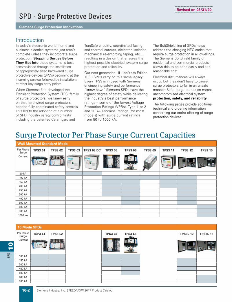
Wall Mounted Standard Mode
Per Phase Surge
Current
TPS3 01 TPS3 02 TPS3 03 TPS3 03 DC TPS3 05 TPS3 06 TPS3 09 TPS3 11 TPS3 12 TPS3 15
50 kA
100 kA
150 kA
200 kA
250 kA
300 kA
400 kA
500 kA
600 kA
800 kA
1000 kA
Surge Protector Per Phase Surge Current Capacities
In today’s electronic world, home and business electrical systems just aren’t complete unless they incorporate surge protection. Stopping Surges Before They Get Into these systems is best accomplished through the installation of appropriately sized hard-wired surge protective devices (SPDs) beginning at the incoming service followed by installations at other key surge entry points.
When Siemens first developed the Transient Protection System (TPS) family of surge protectors, we knew early on that hard-wired surge protectors needed fully coordinated safety controls. This led to the adoption of a number of SPD industry safety control firsts including the patented Ceramgard and
TranSafe circuitry, coordinated fusing and thermal cutouts, dielectric isolation, mechanical re-enforcing taping, etc… resulting in a design that ensures the highest possible electrical system surge protection and reliability.
Our next generation UL 1449 4th Edition TPS3 SPDs carry on this same legacy. Every TPS3 is infused with Siemens engineering safety and performance “know-how.” Siemens SPDs have the highest degree of safety while delivering the industry’s best performance ratings – some of the lowest Voltage Protection Ratings (VPRs), Type 1 or 2 and 20 kA I-nominal ratings (for most models) with surge current ratings from 50 to 1000 kA.
The BoltShield line of SPDs helps address the changing NEC codes that require surge protection in all dwellings. The Siemens BoltShield family of residential and commercial products allows this to be done easily and at a reasonable cost.
Electrical disturbances will always occur, but they don’t have to cause surge protectors to fail in an unsafe manner. Safer surge protection means uncompromised electrical system protection, safety, and reliability.
The following pages provide additional technical and ordering information concerning our entire offering of surge protection devices.
Introduction
10 Mode SPDs
Per Phase Surge
Current
TSP3 L1 TPS3 L2 TPS3 L5 TPS3 L6 TPS3L 12 TPS3L 15
100 kA
150 kA
300 kA
450 kA
500 kA
600 kA
900 kA
SPD - Surge Protective DevicesSiemens Surge Protection Innovations
Revised on 03/31/20

Siemens Industry, Inc. SPEEDFAX™ 2017 Product Catalog 10-3
10
SPD
Surge Arrestor Replacement Discrete or True 10 Mode Style SPDs
Low-voltage surge and lightning arrestors became obsolete when UL 1449 3rd edition went into effect in 2009.
They were replaced with Type 1 SPDs having an I-nominal (In) rating equal to 20 kA. Most all Siemens TPS3s are rated as Type 1, In=20 kA SPDs. However, the style and form factor of tra-ditional surge arrestors is best replaced using our TPS3 03.
For mission critical or high profile applications, a growing number of end users prefer the assur-ance discrete or true 10-mode SPDs provide.
When surges traverse the electrical system via phase to phase conductors, standard SPDs indirectly protect via the line to neutral or line to ground modes of protection. Siemens integral or wall mounted “Discrete” or “True” 10-mode SPDs address L-L surges by incorporating directly connected line to line surge protection elements. This style of SPD provides the “Just in Case” assurance mission critical or high pro-file projects require.
BA C N GMOVs MOVs
MOVs
MOVs
MOVs
MOVs
MOVs
MOVs
MOVs
MOVs
MOVs
= Parallel MOVs
TPS3 03Type 1 SPD
with In = 20 kA
Either at home or in the work place, nearly every electrical load is electronic infused. With today’s power quality being the same as it was 50 years ago, equipment is more susceptible to surge damage and/or disruption generated by normal electrical distribution interactions. Places where lightning activity is minimal are now experiencing more electronic failures due to surges
generated by the day to day operations of equipment like washers and dryers, copiers, chillers, etc.
In response to this susceptibility, code authorities have mandated emergency power distribution equipment now must be protected by a listed SPD. The reasoning is based upon anecdotal understating that surge protected systems are more reliable. Supported by
government studies, the most efficient way to protect electrical systems from surges is through the installation of hardwired SPDs at key points throughout the distribution system. These locations can easily be remembered by memorizing the locations of the acrostic found within the following phrase, “The best surge protected system is a SOLID one,” where each letter of the word SOLID stand for the locations on the electrical system where SPDs should be installed.
The illustration to the right shows “SOLID” locations for a school’s electrical system. Under each ‘SOLID’ location is a Siemens TPS3 model number with surge current capacities matching those to what are typically specified by consultants across North America.
SOLID Protection
ServiceEntrance
Outside loads like Parking Lot Lighting
powered from
distribution panels
Lower voltage distribution
panels powering computers and other electronics
Individual critical
equipment like servers
Data, telephone, and coaxial
cables
TPS30620or
TPS31220
TPS30110or
TPS31110
TPS31110or
TPS30910
TPS30350or
Call TPS Group
TPS30515or
TPS31215
S O L D
SPD - Surge Protective DevicesRecommending Surge Protection

Siemens Industry, Inc. SPEEDFAX™ 2017 Product Catalog10-4
10
SPD
BoltShield™ Surge Protective DevicesBSPD – Commercial Surge Protection for Panel Boards Catalog Logic
Ordering Information
Poles
2 = 2 Pole3 = 3 Pole
Series
BSPD
Voltage Code
A = 120/240V, 1Ø 3W (Fig.1)
B = 240/120V, 3Ø 4W (Fig.3)C = 208Y/120V, 3Ø 4W (Fig.2)D = 240V, 3Ø 3W (Fig.4)E = 480Y/277V, 3Ø, 4W (Fig.1)F = 480V, 3Ø, 3W (Fig.4)G = 600V, 3Ø, 3W (Fig.4)K = 380Y/220V, 3Ø, 4W (Fig.1)L = 600Y/347V, 3Ø, 4W (Fig.1)S = 400Y/230V, 3Ø, 4W (Fig.1)T = 415Y/240V, 3Ø, 4W (Fig.1)
Surge Current Rating
100 = 100kA per Mode/Phase
Catalog # BSPD – 2 – A – 100
Product specificationsGeneral specifications
Maximum surge current rating range 100 kA per phase
UL Type designation SPD Type 1b
UL 1449 I-nominal rating 20kA
UL 1449 short circuit current rating 200kA
Repetitive impulse 5,000 hits
Response time <1 ns
Design specifications
Monolithic distribution grade MOV
Integrated optimized thermal protection
Fits in footprint of BL/BQD, or xGB/3VA41c
Modes of protection (L-N or L-G, L-L)
BSPD Catalog Numbers and UL 1449 performance data
Catalog numbers System voltage L-N (L-G) L-L In SCCR MCOV Siemens breaker form factor
BSPD2A100 120/240V, 1Ø, 3W 600V 900 20kA 200kA 150V 2-P, BL/BQD or xGB/3VA41BSPD3B100 240/120V, 3Ø, 4W 600V/800V 1200 20kA 200kA 150V 3-P, BL/BQD or xGB/3VA41BSPD3C100 208Y/120V, 3Ø, 4W 600V 900 20kA 200kA 150V 3-P, BL/BQD or xGB/3VA41BSPD3D100 240V, 3Ø, 3W 800V 1500 20kA 200kA 280V 3-P, BL/BQD or xGB/3VA41BSPD3E100 480Y/277V, 3Ø, 4W 1000V 1800 20kA 200kA 320V 3-P, BL/BQD or xGB/3VA41BSPD3F100 480V, 3Ø, 3W 1800V 3000 20kA 200kA 550V 3-P, BL/BQD or xGB/3VA41BSPD3G100 600V, 3Ø, 3W 2000V 4000 20kA 200kA 700V 3-P, BL/BQD or xGB/3VA41BSPD3K100 380Y/220V, 3Ø, 4W 900V 1800 20kA 200kA 320V 3-P, BL/BQD or xGB/3VA41BSPD3L100 600Y/347V, 3Ø, 4W 1200V 2500 20kA 200kA 400V 3-P, BL/BQD or xGB/3VA41BSPD3S100 400Y/230V, 3Ø, 4W 900V 1800 20kA 200kA 320V 3-P, BL/BQD or xGB/3VA41BSPD3T100 415Y/240V, 3Ø, 4W 900V 1800 20kA 200kA 320V 3-P, BL/BQD or xGB/3V
Can also be used on 208Y/120V, 1Ø, 3W system.b Type 1 SPDs suitable for use in Type 2 applications.
Benefits of installing multiple BSPDsAdding multiple BSPDs in a single panelboard can increase modes of protection and a surge capacity. See the BoltShield brochure for more details and review an example chart below:Number of BSPDs Connection
Modes of protection
Surge current capacity per mode
Surge current capacity per phase
1 Neutral 3 100kA 100kA2 Neutral + Ground 6 100kA 200kA2 Neutral(2) 3 200kA 200kA3 Neutral(2) + Ground(1) 6 200kA(L-N) + 100kA (L-G) 300kA3 Ground(3) 3 300kA 300kA4 Neutral(2) + Ground(2) 6 200kA 400kA
c Each SPD comes with an adapter for xGB/3VA41 applications. Replacement adapter kit BSPDXGB1 is available, containing 2 and 3 pole adapters (1 each).
BSPD series for panelboards
Diagnostic monitoring specifications
Green/red visual mechanical flag failure indicators Flashing dual color LED (green/red) status indicator Audible alarm with silence switch/button Form C dry contact, 240V AC, 1A max, 48V DC, 0.5A max
Revised on 03/31/20
BSPD Series

Siemens Industry, Inc. SPEEDFAX™ 2017 Product Catalog 10-5
10
SPD
BoltShield™ Surge Protective DevicesQSPD – Residential Surge Protection for Load Centers Catalog Logic
Ordering Information
Poles
2 = 2 Pole3 = 3 Pole
Series
QSPD
Voltage Code
A = 120/240V, 1Ø 3W (Fig.1)
B = 240/120V, 3Ø 4W (Fig.3)C = 208Y/120V, 3Ø 4W (Fig.2)D = 240V, 3Ø 3W (Fig.4)
Surge Current Rating
065P = 65kA per Mode/Phase in retail blister pack packaging
Catalog # QSPD – 2 – A – 065
Product specificationsGeneral specifications
Maximum surge current rating range 65kA per phase
UL Type designation SPD Type 1b
UL 1449 I-nominal rating 20kA
UL 1449 short circuit current rating 200kA
Repetitive impulse 5,000 hits
Response time <1 ns
Design specifications
Monolithic distribution grade MOV
Integrated optimized thermal protection
Fits in footprint of Siemens QP breaker
Modes of protection (L-N or L-G, L-L)
Can also be used on 208Y/120V, 1Ø, 3W system.b Type 1 SPDs suitable for use in Type 2 applications.
Benefits of installing multiple QSPDsAdding multiple QSPDs in a single load center can increase the modes of protection and the surge capacity. See the Boltshield brochure for more details and review the example chart below:Number of QSPDs Connection
Modes of protection
Surge current capacity per mode
Surge current capacity per phase
1 Neutral 3 65kA 65kA2 Neutral + Ground 6 65kA 130kA2 Neutral 3 130kA 130kA3 Neutral(2) + Ground(1) 6 130kA(L-N) + 65kA (L-G) 195kA3 Ground 3 195kA 195kA4 Neutral(2) + Ground(2) 6 130kA 260kA
QSPD series for load centers
Diagnostic monitoring specifications
Green/red visual mechanical flag failure indicators Flashing dual color LED (green/red) status indicator Audible alarm with silence switch/button
QSPD Catalog Numbers and UL 1449 performance dataCatalog numbers System voltage L-N (L-G) L-L In SCCR MCOV Siemens breaker form factor
QSPD2A065Pc 120/240V, 1Ø, 3W 600V 1000 20kA 200kA 150V 2-P, QPQSPD3B065 240/120V, 3Ø, 4W 600V/900V 1200 20kA 200kA 150V 3-P, QPQSPD3C065 208Y/120V, 3Ø, 4W 600V 1000 20kA 200kA 150V 3-P, QPQSPD3D065 240V, 3Ø, 3W 900V 1500 20kA 200kA 280V 3-P, QP
c QSPD2A065P comes in retail style blister pack packaging.
Revised on 03/31/20
QSPD Series
Siemens Industry, Inc. SPEEDFAX™ 2017 Product Catalog10-6
10
SPD
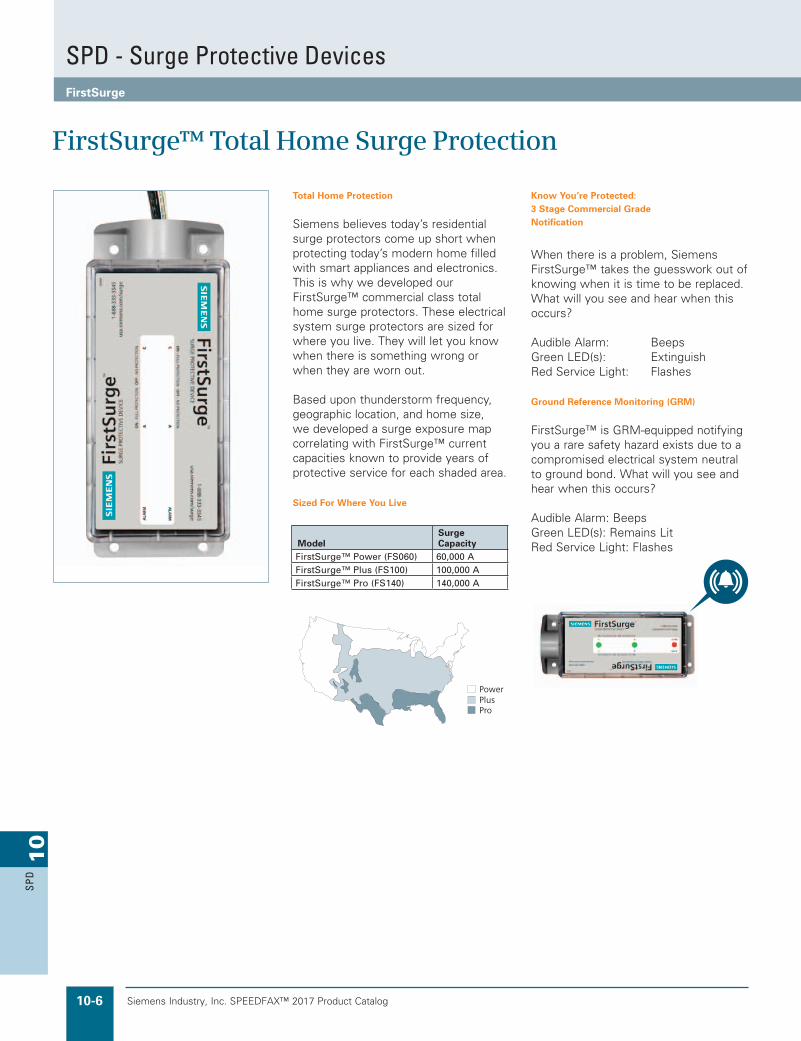
Total Home Protection
Siemens believes today’s residential surge protectors come up short when protecting today’s modern home filled with smart appliances and electronics.This is why we developed our FirstSurge™ commercial class total home surge protectors. These electrical system surge protectors are sized for where you live. They will let you know when there is something wrong or when they are worn out.
Based upon thunderstorm frequency, geographic location, and home size, we developed a surge exposure map correlating with FirstSurge™ current capacities known to provide years of protective service for each shaded area.
Sized For Where You Live
Know You’re Protected: 3 Stage Commercial Grade Notification
When there is a problem, Siemens FirstSurge™ takes the guesswork out of knowing when it is time to be replaced. What will you see and hear when this occurs?
Audible Alarm: BeepsGreen LED(s): ExtinguishRed Service Light: Flashes
Ground Reference Monitoring (GRM)
FirstSurge™ is GRM-equipped notifyingyou a rare safety hazard exists due to acompromised electrical system neutralto ground bond. What will you see andhear when this occurs?
Audible Alarm: BeepsGreen LED(s): Remains LitRed Service Light: FlashesModel
SurgeCapacity
FirstSurge™ Power (FS060) 60,000 AFirstSurge™ Plus (FS100) 100,000 AFirstSurge™ Pro (FS140) 140,000 A
FirstSurge™ Total Home Surge Protection
SPD - Surge Protective DevicesFirstSurge

Siemens Industry, Inc. SPEEDFAX™ 2017 Product Catalog 10-7
10
SPD
Features & Benefits
n UL 1449 Listed, Type 2, Surge Protective Device (SPD)n Rated for 120/240 split phase panels up to 400An Surge Current Capacities:
- 60,000 A
- 100,000 A
- 140,000 An 3 Stage Commercial Grade Notificationn Ground Reference Monitoring (GRM)n Installs onto any brand load centern Type 4 rated outdoor enclosuren 10 year product and connected equipment warranty*
*See warranty for details
Installation Instructions:
FirstSurge™ is a Type 2 SPD. It is suitable for use down-stream of the service disconnect.
Pre-Plan your installation. You need to accomplish the following:
• Meet all National and Local codes (NEC® Article 285 and UL 1449 address SPDs).
• Confirm System voltage to SPD voltage (120V SPD will fail instantly on 240V, 277V, etc.).
• Mount SPD as close to panel or equipment as possible to keep leads short. (long leads hurt performance).
• Ensure leads are as short and straight as possible, including neutral and ground. Use a breaker position that is close to the SPD and the panel’s neutral and ground.
• Recommended breaker size is 20A.
• Make sure system is grounded per NEC® and clear of faults before energizing SPD. (inadvertent system problem may fail SPD).
• Never Hi-Pot test Any SPD. (will prematurely fail SPD).
1. Use voltmeter to check voltages and ensure correct SPD. See Data Sheet for specs and wire-outs.
2. Determine Mounting location – weather resistant equipment may be required.
3. If SPD has optional Flush Mount Kit, pre-plan its installation. See Figure 3. (If flush mounting, be careful to not drop SPD into wall).
4. Remove power from panel/source. Confirm panel/source is deenergized.
5. Identify breaker location and SPD location. Position SPD such that LEDs are best visible. If Flush Mount Kit was ordered, follow Flush Mount instructions and then proceed at #6.
6. Mount SPD – weather resistant applications require additional sealing, etc. (not included)
-- Remove an appropriately sized knockout from panel.
-- Connect conductors as appropriate – short and straight as possible.
7. Label or mark conductors as appropriate (neutral: white, ground: green, energized: black).
8. Make sure system is bonded per NEC® and is clear of hazards or faults before energizing (N-G bonding not per NEC® will fail SPDs: #1 cause of SPD failures).
9. Energize and confirm proper operation of green LED indicators. If any connected phase LED does not illuminate, remove power, check all connections and test again. If any connected phase LED still does not illuminate, contact Siemens Technical Support at: 1-888-333-3545.
10.The SPD is equipped with an audible alarm which will sound in the event of an alarm condition. This indicates a problem with the SPD which requires further evaluation. There is no test or silence switch. De-energizing the SPD will silence the alarm.
Technical SpecificationsSurge Spike Capacity FirstSurge™ Power (FS060) 60,000 A
FirstSurge™ Plus (FS100) 100,000 AFirstSurge™ Pro (FS140) 140,000 A
Line Voltage 120/240 Split Phase, 50/60 HzUL 1449 3rd Ed VPR L-N: 600 V
L-G: 600 VN-G: 600 VL-L: 900 V
Rated Voltage (MCOV) 150V – L-N, L-G, and N-G; 300V – L-LResponse Time <1 nanosecondEnclosure NEMA 4X Indoor and Outdoor RatedSelection InformationFirstSurge™ Power FS060FirstSurge™ Plus FS100FirstSurge™ Pro FS140FirstSurge™ Flush Mount Kit XMFMKIT
A C
GN
BREAKER
s 1-888-333-3545usa.siemens.com/surge
s1-888-333-3545usa.siemens.com/surge
• Use closest breaker to SPD• Locate SPD close to intended breaker
• Keep Leads Short as Possible• Avoid Sharp Bends
• Outdoor installation requires appropriate weather sealing at nipple (gasket, sealing conduit, etc.)
• Rotate FirstSurge™ such that LED indicator is most visible
To Protected Loads
SPD - Surge Protective DevicesFirstSurge
Siemens Industry, Inc. SPEEDFAX™ 2017 Product Catalog10-8
10
SPD
Siemens / Speedfax Previous folio: new page From Julie at APTTVSS
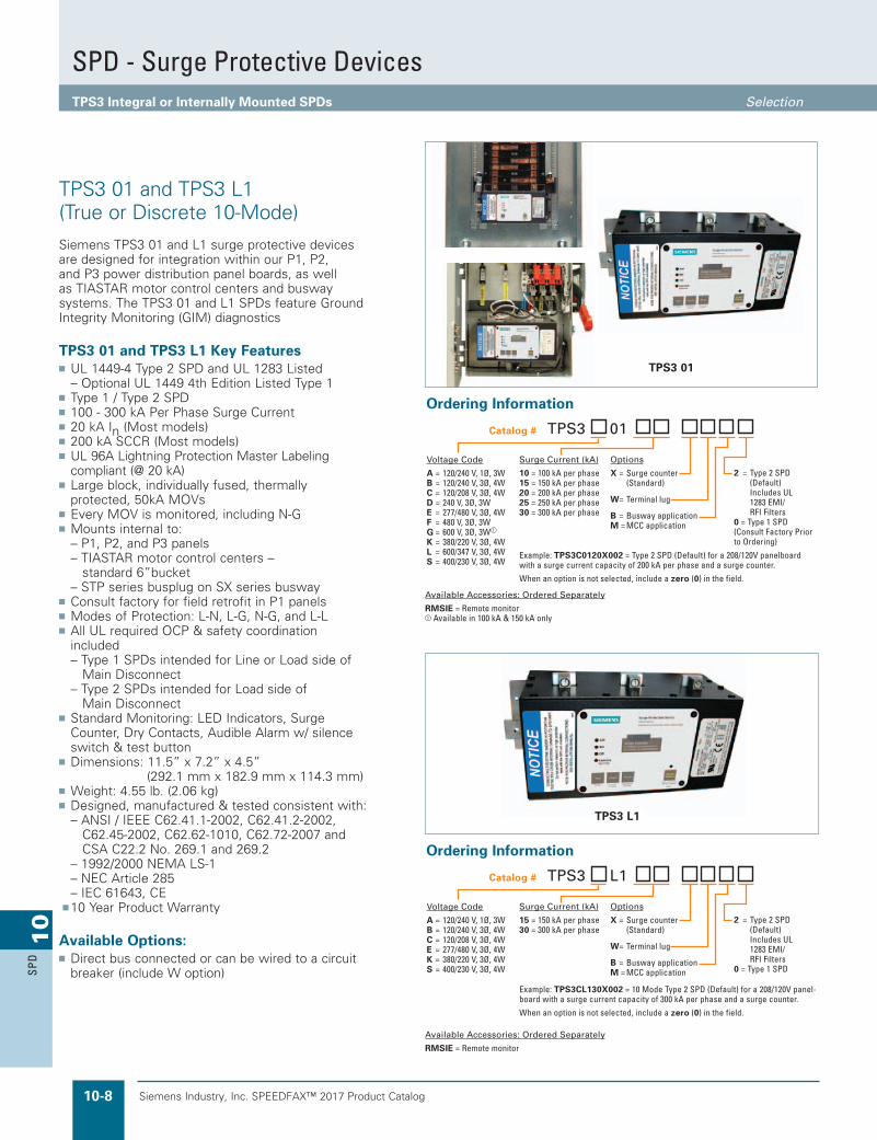
Siemens TPS3 01 and L1 surge protective devices are designed for integration within our P1, P2, and P3 power distribution panel boards, as well as TIASTAR motor control centers and busway systems. The TPS3 01 and L1 SPDs feature Ground Integrity Monitoring (GIM) diagnostics
TPS3 01 and TPS3 L1 Key Featuresn UL 1449-4 Type 2 SPD and UL 1283 Listed – Optional UL 1449 4th Edition Listed Type 1n Type 1 / Type 2 SPDn 100 - 300 kA Per Phase Surge Currentn 20 kA In (Most models)n 200 kA SCCR (Most models)n UL 96A Lightning Protection Master Labeling
compliant (@ 20 kA)n Large block, individually fused, thermally
protected, 50kA MOVsn Every MOV is monitored, including N-Gn Mounts internal to: – P1, P2, and P3 panels – TIASTAR motor control centers –
standard 6”bucket – STP series busplug on SX series buswayn Consult factory for field retrofit in P1 panelsn Modes of Protection: L-N, L-G, N-G, and L-Ln All UL required OCP & safety coordination
included – Type 1 SPDs intended for Line or Load side of Main Disconnect – Type 2 SPDs intended for Load side of
Main Disconnectn Standard Monitoring: LED Indicators, Surge
Counter, Dry Contacts, Audible Alarm w/ silence switch & test button
n Dimensions: 11.5” x 7.2” x 4.5” (292.1 mm x 182.9 mm x 114.3 mm)
n Weight: 4.55 lb. (2.06 kg)n Designed, manufactured & tested consistent with: – ANSI / IEEE C62.41.1-2002, C62.41.2-2002,
C62.45-2002, C62.62-1010, C62.72-2007 and CSA C22.2 No. 269.1 and 269.2
– 1992/2000 NEMA LS-1 – NEC Article 285 – IEC 61643, CE▪n 10 Year Product Warranty
Available Options:n Direct bus connected or can be wired to a circuit
breaker (include W option)
TPS3 01 and TPS3 L1 (True or Discrete 10-Mode)
TPS3 01
Ordering Information
Surge Current (kA)
10 = 100 kA per phase15 = 150 kA per phase20 = 200 kA per phase25 = 250 kA per phase30 = 300 kA per phase
Options
X = Surge counter (Standard)
W= Terminal lug
B = Busway applicationM = MCC application
Voltage Code
A = 120/240 V, 1Ø, 3WB = 120/240 V, 3Ø, 4WC = 120/208 V, 3Ø, 4WD = 240 V, 3Ø, 3WE = 277/480 V, 3Ø, 4WF = 480 V, 3Ø, 3WG = 600 V, 3Ø, 3W
K = 380/220 V, 3Ø, 4WL = 600/347 V, 3Ø, 4WS = 400/230 V, 3Ø, 4W
Available Accessories: Ordered Separately
RMSIE = Remote monitor Available in 100 kA & 150 kA only
Catalog # TPS3 01
Example: TPS3C0120X002 = Type 2 SPD (Default) for a 208/120V panelboard with a surge current capacity of 200 kA per phase and a surge counter.
When an option is not selected, include a zero (0) in the field.
2 = Type 2 SPD (Default) Includes UL 1283 EMI/ RFI Filters0 = Type 1 SPD (Consult Factory Prior to Ordering)
Ordering Information
Surge Current (kA)
15 = 150 kA per phase30 = 300 kA per phase
Options
X = Surge counter (Standard)
W= Terminal lug
B = Busway applicationM = MCC application
Voltage Code
A = 120/240 V, 1Ø, 3WB = 120/240 V, 3Ø, 4WC = 120/208 V, 3Ø, 4WE = 277/480 V, 3Ø, 4WK = 380/220 V, 3Ø, 4WS = 400/230 V, 3Ø, 4W
Available Accessories: Ordered Separately
RMSIE = Remote monitor
Catalog # TPS3 L1
Example: TPS3CL130X002 = 10 Mode Type 2 SPD (Default) for a 208/120V panel-board with a surge current capacity of 300 kA per phase and a surge counter.
When an option is not selected, include a zero (0) in the field.
2 = Type 2 SPD (Default) Includes UL 1283 EMI/ RFI Filters0 = Type 1 SPD
TPS3 L1
SPD - Surge Protective DevicesTPS3 Integral or Internally Mounted SPDs Selection
Siemens Industry, Inc. SPEEDFAX™ 2017 Product Catalog 10-9
10
SPD
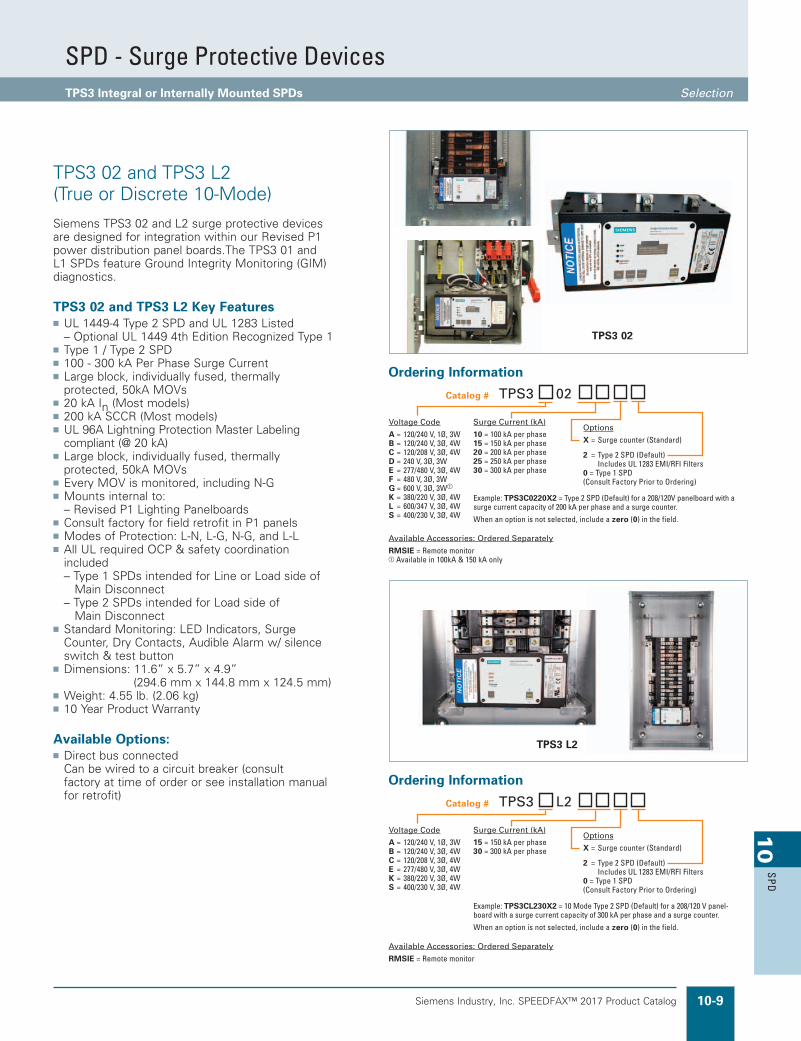
Siemens TPS3 02 and L2 surge protective devices are designed for integration within our Revised P1 power distribution panel boards.The TPS3 01 and L1 SPDs feature Ground Integrity Monitoring (GIM) diagnostics.
TPS3 02 and TPS3 L2 Key Featuresn UL 1449-4 Type 2 SPD and UL 1283 Listed – Optional UL 1449 4th Edition Recognized Type 1n Type 1 / Type 2 SPDn 100 - 300 kA Per Phase Surge Currentn Large block, individually fused, thermally
protected, 50kA MOVsn 20 kA In (Most models)n 200 kA SCCR (Most models)n UL 96A Lightning Protection Master Labeling
compliant (@ 20 kA)n Large block, individually fused, thermally
protected, 50kA MOVsn Every MOV is monitored, including N-Gn Mounts internal to: – Revised P1 Lighting Panelboardsn Consult factory for field retrofit in P1 panelsn Modes of Protection: L-N, L-G, N-G, and L-Ln All UL required OCP & safety coordination
included – Type 1 SPDs intended for Line or Load side of Main Disconnect – Type 2 SPDs intended for Load side of
Main Disconnectn Standard Monitoring: LED Indicators, Surge
Counter, Dry Contacts, Audible Alarm w/ silence switch & test button
n Dimensions: 11.6” x 5.7” x 4.9” (294.6 mm x 144.8 mm x 124.5 mm)
n Weight: 4.55 lb. (2.06 kg)n 10 Year Product Warranty
Available Options:n Direct bus connected Can be wired to a circuit breaker (consult
factory at time of order or see installation manual for retrofit)
TPS3 02 and TPS3 L2 (True or Discrete 10-Mode)
TPS3 02
Ordering Information
Surge Current (kA)
15 = 150 kA per phase30 = 300 kA per phase
Options
X = Surge counter (Standard)
2 = Type 2 SPD (Default) Includes UL 1283 EMI/RFI Filters0 = Type 1 SPD(Consult Factory Prior to Ordering)
Voltage Code
A = 120/240 V, 1Ø, 3WB = 120/240 V, 3Ø, 4WC = 120/208 V, 3Ø, 4WE = 277/480 V, 3Ø, 4WK = 380/220 V, 3Ø, 4WS = 400/230 V, 3Ø, 4W
Available Accessories: Ordered Separately
RMSIE = Remote monitor
Catalog # TPS3 L2
Example: TPS3CL230X2 = 10 Mode Type 2 SPD (Default) for a 208/120 V panel-board with a surge current capacity of 300 kA per phase and a surge counter.
When an option is not selected, include a zero (0) in the field.
Ordering Information
Surge Current (kA)
10 = 100 kA per phase15 = 150 kA per phase20 = 200 kA per phase25 = 250 kA per phase30 = 300 kA per phase
Options
X = Surge counter (Standard)
2 = Type 2 SPD (Default) Includes UL 1283 EMI/RFI Filters0 = Type 1 SPD(Consult Factory Prior to Ordering)
Voltage Code
A = 120/240 V, 1Ø, 3WB = 120/240 V, 3Ø, 4WC = 120/208 V, 3Ø, 4WD = 240 V, 3Ø, 3WE = 277/480 V, 3Ø, 4WF = 480 V, 3Ø, 3WG = 600 V, 3Ø, 3W
K = 380/220 V, 3Ø, 4WL = 600/347 V, 3Ø, 4WS = 400/230 V, 3Ø, 4W
Available Accessories: Ordered Separately
RMSIE = Remote monitor Available in 100kA & 150 kA only
Catalog # TPS3 02
Example: TPS3C0220X2 = Type 2 SPD (Default) for a 208/120V panelboard with a surge current capacity of 200 kA per phase and a surge counter.
When an option is not selected, include a zero (0) in the field.
TPS3 L2
SPD - Surge Protective DevicesTPS3 Integral or Internally Mounted SPDs Selection
Siemens Industry, Inc. SPEEDFAX™ 2017 Product Catalog10-10
10
SPD
Siemens / Speedfax Previous folio: new page From Julie at APTTVSS
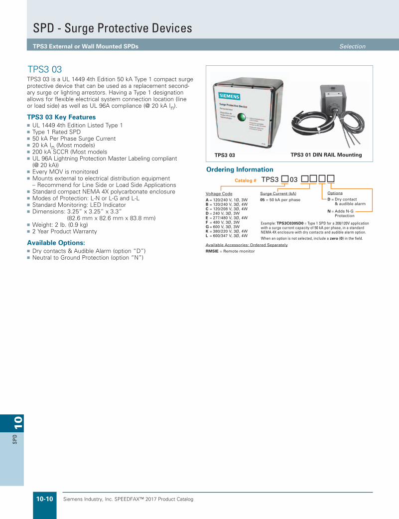
TPS3 03 is a UL 1449 4th Edition 50 kA Type 1 compact surge protective device that can be used as a replacement second-ary surge or lighting arrestors. Having a Type 1 designation allows for flexible electrical system connection location (line or load side) as well as UL 96A compliance (@ 20 kA In).
TPS3 03 Key Featuresn UL 1449 4th Edition Listed Type 1n Type 1 Rated SPDn 50 kA Per Phase Surge Currentn 20 kA In (Most models)n 200 kA SCCR (Most modelsn UL 96A Lightning Protection Master Labeling compliant
(@ 20 kA))n Every MOV is monitoredn Mounts external to electrical distribution equipment – Recommend for Line Side or Load Side Applicationsn Standard compact NEMA 4X polycarbonate enclosuren Modes of Protection: L-N or L-G and L-Ln Standard Monitoring: LED Indicatorn Dimensions: 3.25” x 3.25” x 3.3”
(82.6 mm x 82.6 mm x 83.8 mm)n Weight: 2 lb. (0.9 kg)n 2 Year Product Warranty
Available Options:n Dry contacts & Audible Alarm (option “D”)n Neutral to Ground Protection (option “N”)
TPS3 03
TPS3 01 DIN RAIL Mounting
Ordering Information
Surge Current (kA)
05 = 50 kA per phaseVoltage CodeA = 120/240 V, 1Ø, 3WB = 120/240 V, 3Ø, 4WC = 120/208 V, 3Ø, 4WD = 240 V, 3Ø, 3WE = 277/480 V, 3Ø, 4WF = 480 V, 3Ø, 3WG = 600 V, 3Ø, 3WK = 380/220 V, 3Ø, 4WL = 600/347 V, 3Ø, 4W
Available Accessories: Ordered Separately
RMSIE = Remote monitor
Catalog # TPS3 03
Example: TPS3C0305D0 = Type 1 SPD for a 208/120V application with a surge current capacity of 50 kA per phase, in a standard NEMA 4X enclosure with dry contacts and audible alarm option.
When an option is not selected, include a zero (0) in the field.
Options
D = Dry contact & audible alarm
N = Adds N-G Protection
SPD - Surge Protective DevicesTPS3 External or Wall Mounted SPDs Selection
TPS3 03

Siemens Industry, Inc. SPEEDFAX™ 2017 Product Catalog 10-11
10
SPD
TPS3 09
Performance Data
Siemens Part Number TPS3M0305 TPS3R0305 TPS3P0305Modes of Protection DC+ – DC- , DC+ – Ground, DC- – Ground
Nominal Network Voltage Un 300VDC 600VDC 1000VDC
Technology Large Block, Thermally Protected 50kA MOVs
Maximum Continuous Operating Voltage DC Uc 425VDC 760VDC 1180VDC
Maximum Surge Current (8/20 μs) Imax 50kA 50kA 50kA
Nominal Discharge Current (8/20 μs) In 20kA 20kA 10kA
Voltage Protection Level (3kA 8/20μs) Up <600V <1800V <2500V
Operating Temperature -40oC + 65oC
Response Time tA <1ns
Installation mounting method DIN Rail, Nipple or Bracket
Enclosure Material NEMA 4X Polycarbonate
Wiring (red = + , black = - , green / yellow = gnd) Pre-wired w/3’(~1m) of 8AWG + 6AWG Ground Conductor
Diagnostic circuit Low Consumption LED Indicator
Safety Disconnectors Thermal/Overcurrent Protection; Arc-Breaking Slide Gate
UL Listing UL 1449 Listed as Type 1 SPD as a DC SPD for PV and other types of DC applications
Warranty 5 Years
TPS3 03 DC TPS3 03 DC is available in 300VDC, 600VDC and 1000VDC versions, whichare designed to protect photovoltaic electrical systems. Typical PVinstallation would be on the DC solar panel side and also on the AC side ofthe inverter/converter. AC voltage TPS3 03’s are also available. SPDs arehighly recommended when lightning activity is present to protectsensitive electrical photovoltaic components.
TPS3 03 DC is designed as a stand alone device in a NEMA 4Xpolycarbonate enclosure. Large block, thermally protected 50 kA MOVsare utilized. A green LED illuminates for diagnostic monitoring. TPS3 03DC comes standard with a Tri-Mount installation kit which allows it to beNipple, DIN-rail or Bracket mounted.
Tri-Mount InstallationMounting Kit Included
Diagram Dimensions
SPD - Surge Protective DevicesTPS3 External or Wall Mounted SPDs Selection
Ordering Information
Voltage Code
M = 300 VDC P = 1000 VDC R = 600 VDC
Catalog # TPS3 0305

Siemens Industry, Inc. SPEEDFAX™ 2017 Product Catalog10-12
10
SPD
Siemens TPS3 05 and L5 surge protective devices are designed for integration within our P4 and P5 panelboards as well as distribution switchboards. The TPS3 01 and L1 SPDs feature Ground Integrity Monitoring (GIM) diagnostics.
TPS3 05 and TPS3 L5 Key Featuresn UL 1449-4 Type 2 SPD and UL 1283 Listed – Optional UL 1449 4th Edition Listed Type 1n Type 1 / Type 2 SPDn 100 - 300 kA Per Phase Surge Currentn 20 kA In (Most models)n 200 kA SCCR (Most models)n UL 96A Lightning Protection Master Labeling
compliant (@ 20 kA)n Large block, individually fused, thermally
protected, 50kA MOVsn Every MOV is monitored, including N-Gn Mounts internal to: – P4 & P5 panelboards and distribution switchboardsn Modes of Protection: L-N, L-G, N-G, and L-Ln All UL required OCP & safety coordination
included – Type 1 SPDs intended for Line or Load side of Main Disconnect – Type 2 SPDs intended for Load side of
Main Disconnectn Standard Monitoring: LED Indicators, Surge
Counter, Dry Contacts, Audible Alarm w/ silence switch & test button
n Dimensions: 10” x 17” x 6” (254 mm x 431.8 mm x 152.4 mm)
n Weight: 9.4 lb. (4.2 kg)n Designed, manufactured & tested consistent with: – ANSI / IEEE C62.41.1-2002, C62.41.2-2002,
C62.45-2002, C62.62-1010, C62.72-2007 and CSA C22.2 No. 269.1 and 269.2
– 1992/2000 NEMA LS-1 – NEC Article 285 – IEC 61643, CE▪n 10 Year Product Warranty
Panelboard Features:n Copper or aluminum bus MB or MLO
Switchboard Features:n Copper or aluminum bus 200% rated neutral bus for harmonic-rich
applications CSA, UL 891, UL 67 and NEMA PB-2
TPS3 05 and TPS3 L5 (True or Discrete 10-Mode)
TPS3 05
TPS3 L5
Ordering Information
Surge Current (kA)
10 = 100 kA per phase15 = 150 kA per phase20 = 200 kA per phase25 = 250 kA per phase30 = 300 kA per phase
Voltage Code
A = 120/240 V, 1Ø, 3WB = 120/240 V, 3Ø, 4WC = 120/208 V, 3Ø, 4WD = 240 V, 3Ø, 3WE = 277/480 V, 3Ø, 4WF = 480 V, 3Ø, 3WG = 600 V, 3Ø, 3W
K = 380/220 V, 3Ø, 4WL = 600/347 V, 3Ø, 4WS = 400/230 V, 3Ø, 4W
Available Accessories: Ordered Separately
RMSIE = Remote monitor Available in 100 kA & 150 kA only
Catalog # TPS3 05
Example: TPS3C0530X2 = Type 2 SPD (Default) for a 208/120V power panel with a surge current capacity of 300 kA per phase and a surge counter.
When an option is not selected, include a zero (0) in the field.
Options
X = Surge counter (Standard)
2 = Type 2 SPD (Default) Includes UL 1283 EMI/RFI Filters0 = Type 1 SPD(Consult Factory Prior to Ordering)
Ordering Information
Surge Current (kA)
15 = 150 kA per phase30 = 300 kA per phase
Voltage Code
A = 120/240 V, 1Ø, 3WB = 120/240 V, 3Ø, 4WC = 120/208 V, 3Ø, 4WE = 277/480 V, 3Ø, 4WK = 380/220 V, 3Ø, 4WS = 400/230 V, 3Ø, 4W
Available Accessories: Ordered Separately
RMSIE = Remote monitor
Catalog # TPS3 L5
Example: TPS3C0530X2 = Type 2 SPD (Default) for a 208/120V power panel with a surge current capacity of 300 kA per phase and a surge counter.
When an option is not selected, include a zero (0) in the field.
Options
X = Surge counter (Standard)
2 = Type 2 SPD (Default) Includes UL 1283 EMI/RFI Filters0 = Type 1 SPD(Consult Factory Prior to Ordering)
BA C N GMOVs MOVs
MOVs
MOVs
MOVs
MOVs
MOVs
MOVs
MOVs
MOVs
MOVs
= Parallel MOVs
“True” or “Discrete”10-Mode SPD
SPD - Surge Protective DevicesTPS3 Integral or Internally Mounted SPDs Selection
Siemens Industry, Inc. SPEEDFAX™ 2017 Product Catalog 10-13
10
SPD
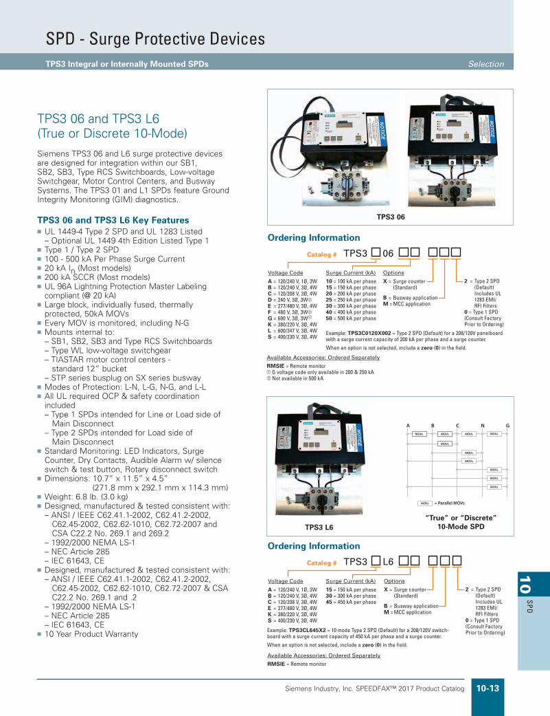
Siemens TPS3 06 and L6 surge protective devices are designed for integration within our SB1, SB2, SB3, Type RCS Switchboards, Low-voltage Switchgear, Motor Control Centers, and Busway Systems. The TPS3 01 and L1 SPDs feature Ground Integrity Monitoring (GIM) diagnostics.
TPS3 06 and TPS3 L6 Key Featuresn UL 1449-4 Type 2 SPD and UL 1283 Listed – Optional UL 1449 4th Edition Listed Type 1n Type 1 / Type 2 SPDn 100 - 500 kA Per Phase Surge Currentn 20 kA In (Most models)n 200 kA SCCR (Most models)n UL 96A Lightning Protection Master Labeling
compliant (@ 20 kA)n Large block, individually fused, thermally
protected, 50kA MOVsn Every MOV is monitored, including N-Gn Mounts internal to: – SB1, SB2, SB3 and Type RCS Switchboards – Type WL low-voltage switchgear – TIASTAR motor control centers -
standard 12” bucket – STP series busplug on SX series buswayn Modes of Protection: L-N, L-G, N-G, and L-Ln All UL required OCP & safety coordination
included – Type 1 SPDs intended for Line or Load side of Main Disconnect – Type 2 SPDs intended for Load side of
Main Disconnectn Standard Monitoring: LED Indicators, Surge
Counter, Dry Contacts, Audible Alarm w/ silence switch & test button, Rotary disconnect switch
n Dimensions: 10.7” x 11.5” x 4.5” (271.8 mm x 292.1 mm x 114.3 mm)
n Weight: 6.8 lb. (3.0 kg)n Designed, manufactured & tested consistent with: – ANSI / IEEE C62.41.1-2002, C62.41.2-2002,
C62.45-2002, C62.62-1010, C62.72-2007 and CSA C22.2 No. 269.1 and 269.2
– 1992/2000 NEMA LS-1 – NEC Article 285 – IEC 61643, CEn Designed, manufactured & tested consistent with: – ANSI / IEEE C62.41.1-2002, C62.41.2-2002, C62.45-2002, C62.62-1010, C62.72-2007 & CSA C22.2 No. 269.1 and .2 – 1992/2000 NEMA LS-1 – NEC Article 285 – IEC 61643, CEn 10 Year Product Warranty
TPS3 06 and TPS3 L6 (True or Discrete 10-Mode)
Ordering Information
Surge Current (kA)
10 = 100 kA per phase15 = 150 kA per phase20 = 200 kA per phase25 = 250 kA per phase30 = 300 kA per phase40 = 400 kA per phase50 = 500 kA per phase
Options
X = Surge counter (Standard)
B = Busway applicationM = MCC application
Voltage Code
A = 120/240 V, 1Ø, 3WB = 120/240 V, 3Ø, 4WC = 120/208 V, 3Ø, 4WD = 240 V, 3Ø, 3Wb
E = 277/480 V, 3Ø, 4WF = 480 V, 3Ø, 3Wb
G = 600 V, 3Ø, 3W
K = 380/220 V, 3Ø, 4WL = 600/347 V, 3Ø, 4WS = 400/230 V, 3Ø, 4W
Available Accessories: Ordered Separately
RMSIE = Remote monitor G voltage code only available in 200 & 250 kAb Not available in 500 kA
Catalog # TPS3 06
Example: TPS3C0120X002 = Type 2 SPD (Default) for a 208/120V panelboard with a surge current capacity of 200 kA per phase and a surge counter.
When an option is not selected, include a zero (0) in the field.
2 = Type 2 SPD (Default) Includes UL 1283 EMI/ RFI Filters0 = Type 1 SPD(Consult Factory Prior to Ordering)
Ordering Information
Options
X = Surge counter (Standard)
B = Busway applicationM = MCC application
2 = Type 2 SPD (Default) Includes UL 1283 EMI/ RFI Filters0 = Type 1 SPD(Consult Factory Prior to Ordering)
Surge Current (kA)
15 = 150 kA per phase30 = 300 kA per phase45 = 450 kA per phase
Voltage Code
A = 120/240 V, 1Ø, 3WB = 120/240 V, 3Ø, 4WC = 120/208 V, 3Ø, 4WE = 277/480 V, 3Ø, 4WK = 380/220 V, 3Ø, 4WS = 400/230 V, 3Ø, 4W
Available Accessories: Ordered Separately
RMSIE = Remote monitor
Catalog # TPS3 L6
Example: TPS3CL645X2 = 10 mode Type 2 SPD (Default) for a 208/120V switch-board with a surge current capacity of 450 kA per phase and a surge counter.
When an option is not selected, include a zero (0) in the field.
TPS3 06
BA C N GMOVs MOVs
MOVs
MOVs
MOVs
MOVs
MOVs
MOVs
MOVs
MOVs
MOVs
= Parallel MOVs
“True” or “Discrete”10-Mode SPDTPS3 L6
SPD - Surge Protective DevicesTPS3 Integral or Internally Mounted SPDs Selection
Siemens Industry, Inc. SPEEDFAX™ 2017 Product Catalog10-14
10
SPD
TPS3 09
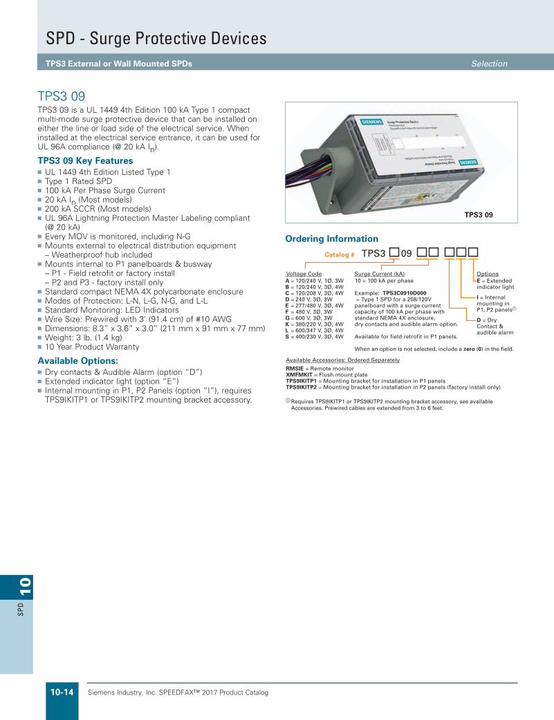
TPS3 09
TPS3 09 is a UL 1449 4th Edition 100 kA Type 1 compact multi-mode surge protective device that can be installed on either the line or load side of the electrical service. When installed at the electrical service entrance, it can be used for UL 96A compliance (@ 20 kA In).
TPS3 09 Key Featuresn UL 1449 4th Edition Listed Type 1n Type 1 Rated SPDn 100 kA Per Phase Surge Currentn 20 kA In (Most models)n 200 kA SCCR (Most models)n UL 96A Lightning Protection Master Labeling compliant
(@ 20 kA)n Every MOV is monitored, including N-Gn Mounts external to electrical distribution equipment – Weatherproof hub includedn Mounts internal to P1 panelboards & busway – P1 - Field retrofit or factory install – P2 and P3 - factory install onlyn Standard compact NEMA 4X polycarbonate enclosuren Modes of Protection: L-N, L-G, N-G, and L-Ln Standard Monitoring: LED Indicatorsn Wire Size: Prewired with 3’ (91.4 cm) of #10 AWGn Dimensions: 8.3” x 3.6” x 3.0” (211 mm x 91 mm x 77 mm)n Weight: 3 lb. (1.4 kg)n 10 Year Product Warranty
Available Options:n Dry contacts & Audible Alarm (option “D”)n Extended indicator light (option “E”)n Internal mounting in P1, P2 Panels (option “I”), requires
TPS9IKITP1 or TPS9IKITP2 mounting bracket accessory.
Ordering Information
OptionsE = Extended indicator light
I = Internal mounting in P1, P2 panels
D = Dry Contact & audible alarm
10 = 100 kA per phase
Example: TPS3C0910D000 = Type 1 SPD for a 208/120V panelboard with a surge current capacity of 100 kA per phase with standard NEMA 4X enclosure, dry contacts and audible alarm option.
Available for field retrofit in P1 panels.
When an option is not selected, include a zero (0) in the field.
A = 120/240 V, 1Ø, 3W B = 120/240 V, 3Ø, 4WC = 120/208 V, 3Ø, 4WD = 240 V, 3Ø, 3WE = 277/480 V, 3Ø, 4WF = 480 V, 3Ø, 3WG = 600 V, 3Ø, 3WK = 380/220 V, 3Ø, 4WL = 600/347 V, 3Ø, 4WS = 400/230 V, 3Ø, 4W
Voltage Code Surge Current (kA)
Available Accessories: Ordered Separately
RMSIE = Remote monitorXMFMKIT = Flush mount plateTPS9IKITP1 = Mounting bracket for installation in P1 panelsTPS9IKITP2 = Mounting bracket for installation in P2 panels (factory install only)
Catalog # TPS3 09
Requires TPS9IKITP1 or TPS9IKITP2 mounting bracket accessory, see available Accessories. Prewired cables are extended from 3 to 6 feet.
SPD - Surge Protective DevicesTPS3 External or Wall Mounted SPDs Selection

Siemens Industry, Inc. SPEEDFAX™ 2017 Product Catalog 10-15
10
SPD
Siemens / Speedfax Previous folio: new page From Julie at APTTVSS
TPS3 11 is a UL 1449 3rd Edition Listed multi-mode Type 1 surge protective device with a per phase surge current capacity that can be increased to 200 kA. In addition, this unit provides UL 1283 listed EMI/RFI or Sine Wave tracking filtering that will condition low energy L-N coupled noise. When installed at the electrical service entrance, it can be used for UL 96A compli-ance (@ 20 kA In).
Standard monitoring includes protection status indication LEDs. Complete protection is intact when the status indicators are illuminated. When protection is lost, the status indicator will extinguish and the red service light will illuminate. An audible alarm and dry contacts are available monitoring options.
A new diagnostic feature integrated within the TPS3 11 is Ground Integrity Monitoring or (GIM) diagnostic indication cir-cuit. Ground Integrity Monitoring or (GIM) diagnostics monitors the health of the electrical system’s neutral to ground bond. If voltage is seen across neutral and ground, the phase indicators will remain illuminated, while the red service light begins to flash alerting the end user that the electrical system grounding needs to be checked and serviced. This feature can be remote-ly monitored when the optional dry contacts are included. Siemens TPS3s are one of the first in the industry to offer this power quality safety and performance indication.
TPS3 11 Key Featuresn UL 1449-4 Type 2 SPD and UL 1283 Listed – Optional UL 1449 4th Edition Listed Type 1n Type 1 / Type 2 SPDn 100, 150, 200 kA Per Phase Surge Currentn 20 kA In (Most models)n 200 kA SCCR (Most models)n UL 96A Lightning Protection Master Labeling compliant
(@ 20 kA)n Every MOV is monitored, including N-Gn Mounts external to electrical distribution equipmentn Standard NEMA 4X polycarbonate enclosure (UL 746C (f1),
UL 94-5VA)n Modes of Protection: L-N, L-G, N-G, and L-Ln Standard Monitoring: LED Indicators and Ground Integrity
Monitoring diagnosticsn Wire size: #8 AWG to #10 AWGn Dimensions: 6” x 6” x 4” (152 mm x 152 mm x 102 mm)n Weight: 5 lb. (2.27 kg)n 10 Year Product Warranty
Available Options:n Dry contacts & Audible Alarm (option “D”)
TPS3 11
TPS3 11
Ordering Information
Example: TPS3C1110D2 = Type 2 SPD (Default) for a 208/120V application with a surge current capacity of 100 kA per phase, in a standard NEMA 4X enclosure with dry contacts and audible alarm option.
When option D is NOT selected, include a zero (0) in the field.
Voltage Code
A = 120/240 V, 1Ø, 3W B = 120/240 V, 3Ø, 4WC = 120/208 V, 3Ø, 4WD = 240 V, 3Ø, 3WE = 277/480 V, 3Ø, 4WF = 480 V, 3Ø, 3WG = 600 V, 3Ø, 3W
K = 380/220 V, 3Ø, 4WL = 600/347 V, 3Ø, 4WS = 400/230 V, 3Ø, 4W
Surge Current (kA)
10 = 100 kA per phase15 = 150 kA per phase20 = 200 kA per phase
Options
2 = Type 2 SPD (Default) Includes UL 1283 EMI/RFI Filters0 = Type 1 SPD(Consult Factory Prior to Ordering)
D = Dry Contacts & audible alarm
Available Accessories: Ordered Separately
RMSIE = Remote monitorKITFMXF = Flush mount plate
Available in 100 kA per phase only
Catalog # TPS3 11
SPD - Surge Protective DevicesTPS3 External or Wall Mounted SPDs Selection
Revised on 01/10/18

Siemens Industry, Inc. SPEEDFAX™ 2017 Product Catalog10-16
10
SPD
Siemens / Speedfax Previous folio: new page From Julie at APTTVSS
TPS3 12 and TPS3 L12 are UL 1449-4 Type 2 and Optional UL 1449 4th Edition surge protective device with a per phase surge current capacity that can be increased to 500 kA (TPS3 L12 up to 450 kA). For mission critical or high profile applications, the TPS3 L12 is our “True” or “Discrete” 10-mode style SPD providing the “Just in Case” assurance of directly connected L-L MOVs.
Both TPS3 12 and TPS3 L12 are UL 1283 Listed incorporating EMI/RFI or Sine Wave tracking filtering designed to condition low energy L-N coupled noise. When installed at the electrical service entrance, it can be used for UL 96A compliance (@ 20 kA In).
Standard monitoring includes protection status indication LEDs, audible alarm, and dry contacts. Complete protection is intact when the status indicators are illuminated. When protection is lost, the status indicator will extinguish, the red service light will illuminate, and the dry contacts will change state. An optional surge counter is available.
A new diagnostic feature integrated within the TPS3 12 and TPS3 L12 is Ground Integrity Monitoring or (GIM) diagnostic indication circuit. Ground Integrity Monitoring or (GIM) diagnostics monitors the health of the electrical system’s neutral to ground bond. If voltage is seen across neutral and ground, the phase indicators will remain illuminated, while the red service light begins to flash alerting the end user that the electrical system grounding needs to be checked and serviced. This feature can be remotely monitored via the dry contact outputs. Siemens TPS3s are one of the first in the industry to offer this power quality safety and performance indication.
TPS3 12 and TPS3 L12 Key Featuresn UL 1449-4 Type 2 SPD and UL 1283 Listed – Optional UL 1449 4th Edition Listed Type 1n Type 1 / Type 2 SPDn TPS3 12: 100 – 500 kA Per Phase Surge Currentn TPS3 L12: 150, 300, 450 kA Phase Surge Currentn 20 kA In (Most models)n 200 kA SCCR (Most models)n UL 96A Lightning Protection Master Labeling compliant
(@ 20 kA)n Every MOV is monitored, including N-Gn Mounts external to electrical distribution equipment – Recommended for line side or load side applicationsn Standard NEMA 1/12/3R/04 ANSI 61 steel enclosuren TPS3 12 Modes of Protection – L-N, L-G, N-G, and L-L n TPS3 L12 Modes of Protection – L-N, L-G, N-G, and L-L
(directly connected L-L elements)n Standard Monitoring: – LED Indicators – Ground Integrity Monitoring diagnostics – Dry Contacts – Audible alarm with silence switch and test buttonn Wire size: #8 AWG to 1/0n Dimensions: 12” x 12” x 7” (305 mm x 305 mm x 178 mm)c
n Weight: 20 lb. (9.07 kg)c
n 10 Year Product Warranty
Available Options:n Internal rotary disconnectn Thru-door disconnect
TPS3 12 and TPS3 L12 (True or Discrete 10-Mode)
TPS3 12
Ordering Information
Ordering Information
TPS3 L12
BA C N GMOVs MOVs
MOVs
MOVs
MOVs
MOVs
MOVs
MOVs
MOVs
MOVs
MOVs
= Parallel MOVs
“True” or “Discrete”10-Mode SPD
Surge Current (kA)
10 = 100 kA per phase15 = 150 kA per phase20 = 200 kA per phase25 = 250 kA per phase30 = 300 kA per phase40 = 400 kA per phase50 = 500 kA per phase
Enclosure
0 = Standard NEMA 1/12/3R/4 SteelV = NEMA 4X non- metallicS = NEMA 4X stainless steelF = NEMA 1 flush mountP = NEMA 1 screwcover pullbox with extended display on 6ft cable for line side mounting in SWBD/SWGR
Voltage Code
A = 120/240 V, 1Ø, 3W B = 120/240 V, 3Ø, 4WC = 120/208 V, 3Ø, 4WD = 240 V, 3Ø, 3W
E = 277/480 V, 3Ø, 4WF = 480 V, 3Ø, 3W
G = 600 V, 3Ø, 3Wb
K = 380/220 V, 3Ø, 4WL = 600/347 V, 3Ø, 4WS = 400/230 V, 3Ø, 4W
Options
2 = Type 2 SPD (Default) Includes UL 1283 EMI/ RFI Filters0 = Type 1 SD(Consult Factory Prior to Ordering)
D = Internal rotary disconnectT = Thru-door disconnect
X = Surge Counter (Standard)Available Accessories: Ordered Separately
RMSIE = Remote monitor Not available in 500 kAb Available in 100 kA, 150 kA, 200 kA & 250 kA only
Catalog # TPS3 12
Example: TPS3C12100XD2 = Type 2 SPD (Default) for a 208/120V application with a surge current capacity of 100kA per phase, in a standard NEMA 1/12/3R/4 enclosure with a surge counter and internal rotary disconnect option.
When option X, T, or D are NOT selected, include a zero (0) in the field.
Surge Current (kA)
15 = 150 kA per phase30 = 300 kA per phase45 = 450 kA per phase
Enclosure
0 = Standard NEMA 1/12/3R/4 SteelV = NEMA 4X non- metallicS = NEMA 4X stainless steelF = NEMA 1 flush mountP = NEMA 1 screwcover pullbox with extended display on 6ft cable for line side mounting in SWBD/SWGR
Voltage Code
A = 120/240 V, 1Ø, 3W B = 120/240 V, 3Ø, 4WC = 120/208 V, 3Ø, 4WE = 277/480 V, 3Ø, 4WK = 380/220 V, 3Ø, 4WS = 400/230 V, 3Ø, 4W
Options
2 = Type 2 SPD (Default) Includes UL 1283 EMI/ RFI Filters0 = Type 1 SD(Consult Factory Prior to Ordering)
D = Internal rotary disconnectT = Thru-door disconnect
X = Surge Counter (Standard)Available Accessories: Ordered Separately
RMSIE = Remote monitor
Catalog # TPS3 L12
Example: TPS3CL12150XD2 = 10 Mode, Type 2 SPD (Default) for a 208/120V application with a surge current capacity of 150kA per phase, in a standard NEMA 1/12/3R/4 enclosure with a surge counter and internal rotary disconnect option.
When an option is NOT selected, include a zero (0) in the field.
c Internal disconnect options and other NEMA ratings may increase enclosure size and weight
SPD - Surge Protective DevicesTPS3 External or Wall Mounted SPDs Selection

Siemens Industry, Inc. SPEEDFAX™ 2017 Product Catalog 10-17
10
SPD
Siemens / Speedfax Previous folio: new page From Julie at APTTVSS
TPS3 15 and TPS3 L15 are UL 1449-4 Type 2 and Optional UL 1449 4th Edition surge protective device with a per phase surge current capacity that can be increased to 1000 kA (TPS3 L15 up to 900 kA). For mission critical or high profile applications, the TPS3 L15 is our “True” or “Discrete” 10-mode style SPD providing the “Just in Case” assurance of directly connected L-L MOVs.
Both TPS3 15 and TPS3 L15 are UL 1283 Listed incorporating EMI/RFI or Sine Wave tracking filtering designed to condition low energy L-N coupled noise. When installed at the electrical service entrance, it can be used for UL 96A compliance (@ 20 kA In).
Standard monitoring includes protection status indication LEDs, audible alarm, and dry contacts. Complete protection is intact when the status indicators are illuminated. When protection is lost, the status indicator will extinguish, the red service light will illuminate, and the dry contacts will change state. An optional surge counter is available.
A new diagnostic feature integrated within the TPS3 15 and TPS3 L15 is Ground Integrity Monitoring or (GIM) diagnostic indication circuit. Ground Integrity Monitoring or (GIM) diagnostics monitors the health of the electrical system’s neutral to ground bond. If voltage is seen across neutral and ground, the phase indicators will remain illuminated, while the red service light begins to flash alerting the end user that the electrical system grounding needs to be checked and serviced. This feature can be remotely monitored via the dry contact outputs. Siemens TPS3s are one of the first in the industry to offer this power quality safety and performance indication.
TPS3 15 and TPS3 L15 Key Featuresn UL 1449-4 and UL 1283 Listed – Optional UL 1449 4th Edition Listed Type 1n Type 1 / Type 2 SPDn TPS3 15: 400 – 1000 kA Per Phase Surge Currentn TPS3 L15: 600 and 900 kA Phase Surge Currentn 20 kA In (Most models)n 200 kA SCCR (Most models)n UL 96A Lightning Protection Master Labeling compliant
(@ 20 kA)n Every MOV is monitored, including N-Gn Mounts external to electrical distribution equipment – Recommended for line side or load side applicationsn Standard NEMA 1/12/3R/04 ANSI 61 steel enclosuren TPS3 15 Modes of Protection – L-N, L-G, N-G, and L-L n TPS3 L15 Modes of Protection – L-N, L-G, N-G, and L-L
(directly connected L-L elements)n Internal rotary disconnect switch included n Standard Monitoring: – LED Indicators – Ground Integrity Monitoring diagnostics – Dry Contacts – Audible alarm with silence switch and test buttonn Wire size: #8 AWG to 1/0n Dimensions: 20” x 20” x 7” (508 mm x 508 mm x 178 mm)
n Weight: 64 lb. (29 kg)
n 10 Year Product Warranty
Available Options:n Thru-door disconnect
TPS3 15 and TPS3 L15 (True or Discrete 10-Mode)
TPS3 15
Ordering Information
Surge Current (kA)
40 = 400 kA per phase
50 = 500 kA per phase
60 = 600 kA per phase80 = 800 kA per phase1K = 1000 kA per phase
Enclosure
0 = Standard NEMA 1/12/3R/4 SteelV = NEMA 4X non- metallicS = NEMA 4X stainless steelF = NEMA 1 flush mountP = NEMA 1 screwcover pullbox with extended display on 5ft cable for line side mounting in SWBD/SWGR
Voltage Code
A = 120/240 V, 1Ø, 3W B = 120/240 V, 3Ø, 4WC = 120/208 V, 3Ø, 4WD = 240 V, 3Ø, 3Wb
E = 277/480 V, 3Ø, 4WF = 480 V, 3Ø, 3Wb
G = 600 V, 3Ø, 3Wc
K = 380/220 V, 3Ø, 4WL = 600/347 V, 3Ø, 4WS = 400/230 V, 3Ø, 4W
Options
2 = Type 2 SPD (Default) Includes UL 1283 EMI/ RFI Filters0 = Type 1 SD(Consult Factory Prior to Ordering)
T = Thru-door disconnect
X = Surge Counter (Standard)
Available Accessories: Ordered Separately
RMSIE = Remote monitor Available in G voltage code onlyb Available in 600 kA & 800 kA onlyc Available in 400 kA & 500 kA only
Catalog # TPS3 15
Example: TPS3C1560SX02 = Type 2 SPD (Default) for a 208/120V application with a surge current capacity of 600 kA per phase, in a NEMA 4X stainless steel enclosure with a surge counter and standard disconnect switch.
When an option is NOT selected, include a zero (0) in the field.
Ordering Information
TPS3 L15
BA C N GMOVs MOVs
MOVs
MOVs
MOVs
MOVs
MOVs
MOVs
MOVs
MOVs
MOVs
= Parallel MOVs
“True” or “Discrete”10-Mode SPD
Surge Current (kA)
60 = 600 kA per phase90 = 900 kA per phase
Enclosure
0 = Standard NEMA 1/12/3R/4 SteelV = NEMA 4X non- metallicS = NEMA 4X stainless steelF = NEMA 1 flush mountP = NEMA 1 screwcover pullbox with extended display on 5ft cable for line side mounting in SWBD/SWGR
Voltage Code
A = 120/240 V, 1Ø, 3W B = 120/240 V, 3Ø, 4WC = 120/208 V, 3Ø, 4WE = 277/480 V, 3Ø, 4WK = 380/220 V, 3Ø, 4WS = 400/230 V, 3Ø, 4W
Options
2 = Type 2 SPD (Default) Includes UL 1283 EMI/ RFI Filters0 = Type 1 SD(Consult Factory Prior to Ordering)
T = Thru-door disconnect
X = Surge Counter (Standard)
Available Accessories: Ordered Separately
RMSIE = Remote monitor
Catalog # TPS3 L15
Example: TPS3CL15600X02 = 10 Mode, Type 2 SPD (Default) for a 208/120V application with a surge current capacity of 600 kA per phase, in a standard NEMA 1/12/3R/4 enclosure with a surge counter.
When an option is NOT selected, include a zero (0) in the field.
Other NEMA ratings may increase enclosure size and weight.
SPD - Surge Protective DevicesTPS3 External or Wall Mounted SPDs Selection
Siemens Industry, Inc. SPEEDFAX™ 2017 Product Catalog10-18
10
SPD
What is a surge protective device or SPD? A Surge Protective Device is a device that attenuates (reduces in magnitude) random, high energy, short duration overvoltages caused by lightning, utilities, switching, etc. Such anomalies occur in the form of voltage and current spikes with a duration of less than half an ac voltage cycle. These high energy power spikes can damage sensitive electronic equipment, such as computers, instrumentation, and process controllers.
How do SPDs work? Surge Suppressors divert high energy power away from a load by providing a lower impedance path to common point earth ground. This is similar in concept to pressure relief valves that protect water heaters from overpressure. Surge suppressors used most often for protection of AC Power have metal oxide varistors (MOVs) connected in parallel.
Where are SPDs installed? AC voltage surge suppressors are typically installed in these three areas: at a utility service entrance for protection of an entire facility, in distribution panelboards and switchboards for protection of sensitive downstream loads; connected to a wall outlet for individual protection of a specific piece of equipment, such as a computer or solid-state controller.
What is clamping voltage? Clamping voltage, also referred to as peak let through or suppressed voltage rating, is the amount of voltage a surge suppressor permits to pass through it to the attached load during a transient event. Clamping voltage is a performance measurement of a surge suppressor’s ability to attenuate a transient. For example, a surge suppressor might limit a 6,000V surge so that only 700V is ‘visible’ to the load. The Voltage Protection Rating is 700V, commonly called Clamping Voltage. This performance value is confirmed by Underwriters Laboratories during tests conducted while evaluating a surge suppressor for listing.
What is surge current capacity? Surge current capacity is the maximum amount of surge current that a surge suppressor can pass for a single transient event. This level is used to indicate the protection capacity of a particular surge suppressor design, and when specifying surge suppressors. For example, in a high exposure application with very large transients present from lightning, a higher level surge current capacity might be desired. Be aware that surges have natural limitations and that larger surge current capacity tends to add redundancy rather than the implied ability to handle an extremely large surge. For
example, an entire lightning strike cannot go through wire; it is much like trying to put the output from a fire hose through a soda straw. Consequently, suppressors do not need to be sized for entire lightning strikes. There are valid reasons for adding excess surge current capacity for redundancy reasons.
What types of components make up a SPD? The device most commonly used in AC voltage surge suppressors are MOVs, a solid-state device made of zinc oxide materials. MOVs are voltage sensitive semiconductors, which change from high impedance to low impedance when sensing an overvoltage condition. MOVs are packaged for specific voltages and current handling capacities. Other devices (more typically found in DC applications) include single junction diodes and gas tubes that ionize at preset voltages.
What features should be considered when selecting SPDs? Two important areas to consider during the selection of a surge suppressor are performance and safety, and include the following criteria: Performance: 1) surge current capacity; and 2) clamping voltage. Safety: 1) the individual suppression circuit should be fused to clear an inoperative MOV during an extreme transient event, and 2) provide overcurrent protection for the surge suppressor during a fault condition.
What surge current capacity is required? Surge current capacity is dependent on the application and the amount of required protection. The selection of the proper surge suppressor is not an exact science and cannot be scien-tifically calculated from a standard algorithm.
Questions to consider when specifying the proper surge current capacity for a surge suppressor include:
n What is the geographic location of the facility and it’s susceptibility to lightning? (For example, Florida is a high-lightning area; California is a low lightning area.)
n Is the facility in a rural or urban setting?
n Is the facility the tallest building around?
n Is the facility at the end of the utility grid?
n If it is an existing facility, what is its power quality history?
Based on the above information, and taking into account the cost of protection, the following is a good rule of thumb: a surge suppressor with a surge current capacity in the range of 100kA to 300kA would be used in conjunction with a service entrance panelboard or switchboard. A surge suppressor with a surge current capacity in the range of 100kA to 200kA would be used in conjunction with a downstream panelboard
Frequently Asked Questions
SPD - Surge Protective DevicesSurge Protective Devices FAQ