SURGE CONDITIONS IN A 30” FORCE MAIN Bo Copeland, … · Copeland Proving that Bladder Surge...
6
Copeland Proving that Bladder Surge Tanks Cured Excessive Surge Conditions in a 30” Force Main Page 1 of 6 PROVING THAT BLADDER SURGE TANKS CURED EXCESSIVE SURGE CONDITIONS IN A 30” FORCE MAIN Bo Copeland, P.E., Hazen and Sawyer, P.C. Sean FitzGerald, P.E., Hazen and Sawyer, P.C. Background The Sanitation District No. 1 of Northern Kentucky (SD1) provides wastewater collection and treatment for approximately 350,000 people in Campbell, Kenton, and Boone Counties. SD1’s system includes about 140 pump stations, 75 miles of force mains and about 1,500 feet of gravity sanitary sewers. The Lakeview Pump Station (PS) in Fort Wright, Kentucky, which was constructed in the mid 1970s, is a wet well-dry well PS with 8 centrifugal pumps (4 parallel sets of 2 pumps in series) with a combined pumping capacity of 21 MGD. The Lakeview force main (FM), which is primarily 30-inch-diameter prestressed concrete cylinder pipe (PCCP), is over 3 miles long. The system operates at pressures over 200 psi and was experiencing transient pressures (surge) up to 500 psi. Full vacuum conditions and subsequent vapor cavity collapse were also occurring in the higher portions of the FM (Figure 1) during surge events, which had routinely generated vibrations and noise at nearby homes resulting in customer complaints. In June 2009, a power outage at the PS created surge conditions that split a 14” gate valve in the PS (Figure 2), flooded the dry well and submerged the pumps and motors. Evaluation of the Problem To alleviate both the vapor cavity collapse and high-pressure surge conditions resulting from power outages and other emergency pump shutdowns as well as normal pump starts and stops, SD1 contracted with Hazen and Sawyer (H&S) to evaluate alternatives for a permanent solution. The evaluation included development and detailed calibration of a surge model using KYPipe’s PIPE2008 Surge software. A unique feature of the calibration was the use of transient pressure recorders capable of capturing dynamic pressure readings up to 1,000 Hz during surge
Transcript of SURGE CONDITIONS IN A 30” FORCE MAIN Bo Copeland, … · Copeland Proving that Bladder Surge...
Copeland Proving that Bladder Surge Tanks Cured Excessive Surge Conditions in a 30” Force Main Page 1 of 6
PROVING THAT BLADDER SURGE TANKS CURED EXCESSIVE SURGE CONDITIONS IN A 30” FORCE MAIN
Bo Copeland, P.E., Hazen and Sawyer, P.C.
Sean FitzGerald, P.E., Hazen and Sawyer, P.C. Background
The Sanitation District No. 1 of Northern Kentucky (SD1) provides wastewater collection
and treatment for approximately 350,000 people in Campbell, Kenton, and Boone Counties.
SD1’s system includes about 140 pump stations, 75 miles of force mains and about 1,500 feet of
gravity sanitary sewers. The Lakeview Pump Station (PS) in Fort Wright, Kentucky, which was
constructed in the mid 1970s, is a wet well-dry well PS with 8 centrifugal pumps (4 parallel sets
of 2 pumps in series) with a combined pumping capacity of 21 MGD. The Lakeview force main
(FM), which is primarily 30-inch-diameter prestressed concrete cylinder pipe (PCCP), is over 3
miles long. The system operates at pressures over 200 psi and was experiencing transient
pressures (surge) up to 500 psi. Full vacuum conditions and subsequent vapor cavity collapse
were also occurring in the higher portions of the FM (Figure 1) during surge events, which had
routinely generated vibrations and noise at nearby homes resulting in customer complaints. In
June 2009, a power outage at the PS created surge conditions that split a 14” gate valve in the PS
(Figure 2), flooded the dry well and submerged the pumps and motors.
Evaluation of the Problem
To alleviate both the vapor cavity collapse and high-pressure surge conditions resulting
from power outages and other emergency pump shutdowns as well as normal pump starts and
stops, SD1 contracted with Hazen and Sawyer (H&S) to evaluate alternatives for a permanent
solution. The evaluation included development and detailed calibration of a surge model using
KYPipe’s PIPE2008 Surge software. A unique feature of the calibration was the use of transient
pressure recorders capable of capturing dynamic pressure readings up to 1,000 Hz during surge

Copeland Proving that Bladder Surge Tanks Cured Excessive Surge Conditions in a 30” Force Main Page 2 of 6
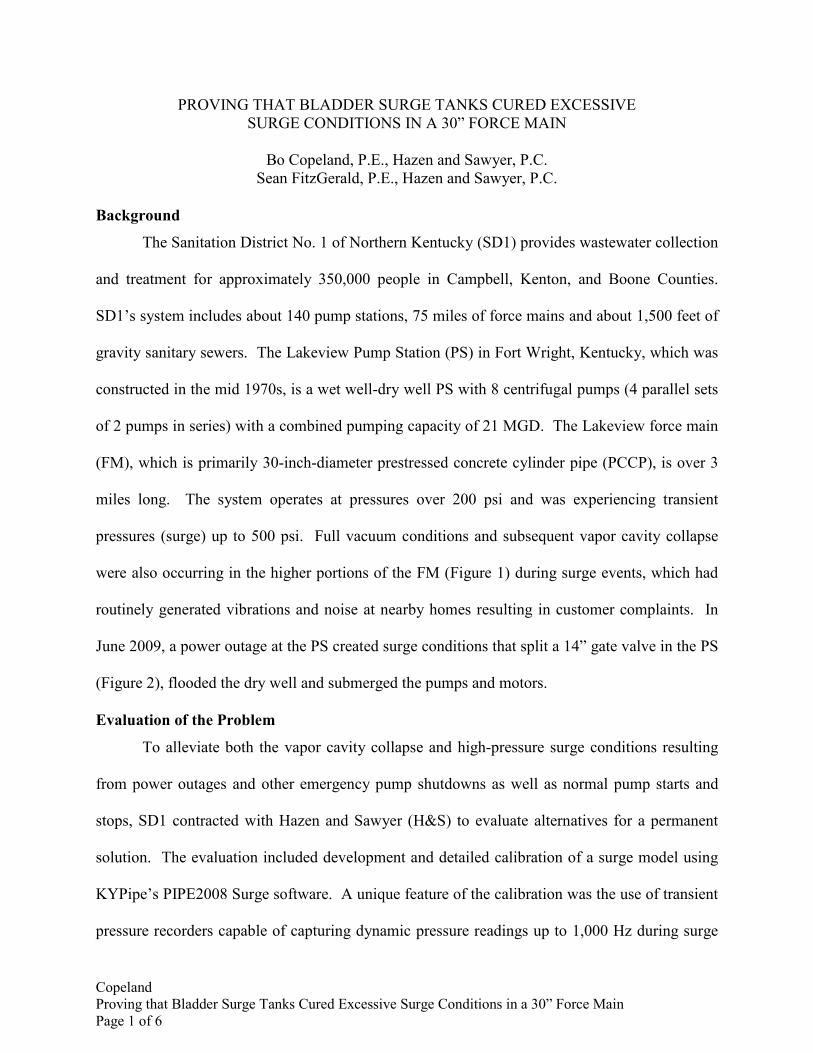
events that may only last for a few milliseconds (Figure 3). Pressure recorders were placed at the
PS and on the problematic section of the FM to monitor normal pump operation and emergency
pump shutdown scenarios (Figures 4 & 5). The calibration yielded a good understanding of the
root causes of transients in the system, including vapor cavity collapse in the FM.
Once the model was developed and calibrated (Table 1), alternatives were evaluated to
address transients at the PS and in the FM. These alternatives included installation of one or
more bladder surge tanks at several locations in various combinations with pump control valves,
fast-closing check valves, surge relief valve and/or combination air/vacuum valves.
Implementation of the Solution
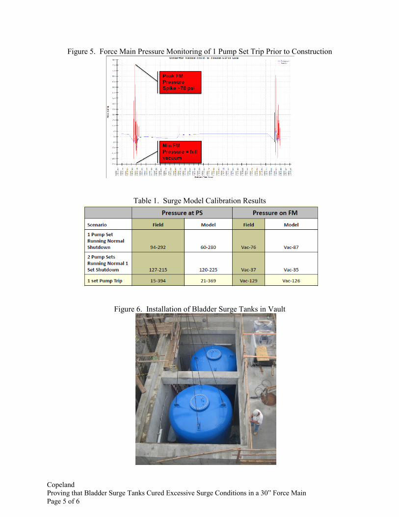
Installation of two 7,500-gallon bladder surge tanks and four fast-closing check valves
was selected as the most reliable, cost-effective solution to control surge conditions in the pump
station and force main. Due to space constraints, the surge tanks were installed in a below-
ground vault (Figure 6) outside of the pump station. Various instrumentation and controls were
installed to monitor operation of the surge tanks, protect the tank components, and monitor surge
pressures. These devices were used during and subsequent to startup to assess the effectiveness
of the improvements and to more precisely calibrate the surge model. H&S coordinated with the
contractor, surge tank manufacturer and SD1 to conduct several rounds of startup testing and
performance monitoring, which were completed in January 2011.
The performance monitoring consisted of monitoring the flow rates from each pump set,
water levels in the two bladder surge tanks, and transient pressures at multiple locations in the PS
and on the FM. The data were analyzed and compared to pre-construction conditions and to the
specified design criteria and performance conditions. Results showed successful control of
pressures in the FM (Figure 7) and dramatic improvement in the PS (Figure 8). However, under
pump trip conditions, check valve slam was resulting in pressure spikes in the PS that exceeded

Copeland Proving that Bladder Surge Tanks Cured Excessive Surge Conditions in a 30” Force Main Page 3 of 6
the specified performance criteria. Thus, the project team coordinated with the manufacturers of
the surge tanks and check valves to make modifications to the check valves that resulted in a
significant reduction of these pressure spikes. Further operational adjustments brought the surge
pressures within the specified limits—even under worst-case conditions (Figure 9).
The refined surge model that resulted from this effort has been used to evaluate
alternatives for future PS and FM upgrades. The primary transient pressure monitor and other
instrumentation at the PS will remain for long-term performance evaluation, and the data
collected during the first year will be used as a baseline against which to evaluate future system
performance. SD1 will continue to monitor operating data so that any problems can be promptly
identified and addressed to ensure long-term reliability of the improvements.
Conclusion
This project demonstrates a successful approach to implementing and evaluating the
effectiveness of surge improvements in an existing pumping system. It teaches important lessons
on the implementation of surge improvements, including the value of performance monitoring
and the importance of coordination among the owner, engineer, and equipment manufacturers
throughout design and construction. This paper will discuss the following topics:
• Surge model calibration, including modeling challenges and limitations • Design considerations for use of bladder surge tanks and check valves to control surge • Performance monitoring procedures, results and subsequent equipment modifications • Comparison of pre- and post-construction surge conditions • Comparison of post-construction surge conditions to model-predicted surge conditions • Evaluation of equipment performance vs. manufacturers’ literature & specified criteria • Challenges and lessons learned from the project.
Through the successes and lessons learned from this project, participants will gain a better
understanding of transient pressure concerns, surge attenuation, bladder surge tanks, and
transient pressure monitoring.

Copeland Proving that Bladder Surge Tanks Cured Excessive Surge Conditions in a 30” Force Main Page 4 of 6
Figure 1. Lakeview Force Main Profile
Figure 2. 14” Gate Valve at Lakeview
Pump Station after June 2009 Surge Event
Figure 3. TP-1 Transient Pressure Monitor Data Recording Functionality (Courtesy of
Pipetech International)
Figure 4. Pump Station Pressure Monitoring of 1 Pump Set Trip Prior to Construction
Copeland Proving that Bladder Surge Tanks Cured Excessive Surge Conditions in a 30” Force Main Page 5 of 6
Figure 5. Force Main Pressure Monitoring of 1 Pump Set Trip Prior to Construction
Table 1. Surge Model Calibration Results
Figure 6. Installation of Bladder Surge Tanks in Vault

Copeland Proving that Bladder Surge Tanks Cured Excessive Surge Conditions in a 30” Force Main Page 6 of 6
Figure 7. Force Main Pressure Monitoring of 1 Pump Set Trip with Surge Tanks In Service
Figure 8. Pump Station Pressure Monitoring of 1 Pump Set Trip with Surge Tanks in Service
Figure 9. Pump Station Pressure Monitoring of 4 Pump Sets Trip with Surge Tanks in Service,
After Additional Modifications