SurfCAM 2000 Primer for AAE 490t Micro Air Vehicles 2 · The SHADE button displays the surface as...
12
SurfCAM 2000 Primer for AAE 490t Micro Air Vehicles by Joseph Harber Purdue University
Transcript of SurfCAM 2000 Primer for AAE 490t Micro Air Vehicles 2 · The SHADE button displays the surface as...

SurfCAM 2000 Primer
for
AAE 490t Micro Air Vehicles
by
Joseph Harber
Purdue University

2
Introduction While several SurfCAM tutorials currently exist, none specifically address the needs of the Micro Air Vehicles group. This primer’s aim is to minimize the time needed for new students to learn the basics of the CNC process and to provide a practical introduction to the techniques used to produce wings for future MAV research. Airfoils Airfoil contour data is available in several places such as books and more conveniently on the Internet. Websites often list the coordinates with an x-column and a y-column. The easiest way to create a useable airfoil is to use AutoCAD, which requires the coordinates be in ordered pairs. While this process is always tedious, the fastest way yet found is to copy the coordinates from the page and past them into WordPad. Use the EDIT>REPLACE command to find spaces and replace with nothing. Using the comma an arrow keys, go down the center of the column separating the pairs with a column and no space. Useable coordinates should look like those in figure 1.1.
Figure 1.1: Airfoil Coordinates SHOW/HIDE is on to emphasize that there are NO spaces in the file. To import the data into AutoCAD, select all of the coordinates and copy them. Begin the POLYLINE command in AutoCAD and click the cursor on the command line. Paste the ordered pairs in the box and an airfoil will be created. If there is a point that is obviously not where is

3
DXF file. In the open menu of SurfCAM, change the file type to .dxf before opening the proper directory. Figure 1.2 shows a rotated airfoil.
Figure 1.2: An airfoil in AutoCAD. Views and Navigation Now in SurfCAM, a look at viewing and navigation is in order. On the toolbar, one will notice two kinds of views: VIEW and construction view, or CVIEW. View describes the viewpoint of the observer and does not change anything on the drawing. CView is similar to the UCS of AutoCAD but one will notice that there are two sets of unit vectors displayed. The large, blue axis in the lower left corner is what the CNC router will use when it cuts the part, while the small the CVIEW changes the colored one on the drawing. The button on the toolbar called Coord: dictates which set is used to make the drawing and later to set tool paths. It is easiest to just set this one to View, meaning locations are relative to the colored CVIEW set of axis. The upper toolbar contains five buttons for viewing. Their uses are best explained by their names as shown in figure 1.3.

4
Because SurfCAM has a rather threadbare toolbar, most commands are initiated through the menu bar at the top of the screen and continued on the action toolbar, which displays the options of the activated command. For example, to create a surface one goes to CREATE>SURFACE on the menu bar, then chooses the remaining parameters on the action toolbar. Creating a Wing Outline To create a surface such as a wing requires two airfoils, three if it is not a simple rectangle. The following example will demonstrate how to create a swept, tapered wing with several degrees of dihedral and geometric twist. The first step is to set the coordinate system. Set the COORD button to View and then click on the VIEW toolbar button, with the eye. It is easiest to do most of the construction using the isometric view and the top construction view, so type 7 [TAB] 1 and [ENTER]. Zoom out using the toolbar once or twice to get a better view. This wing will have a root chord of 4 inches. Because the airfoil is of unit length, the desired chord can be obtained using the scale function. Use EDIT>TRANSFORM on the menu bar. This brings up the transform action toolbar. For this set the move button and then click on scale. Instructions are displayed on the lower left of the screen. Select the airfoil and a dialog box asks for the scale factor. In this case enter 4 for the chord. The instruction bar will ask for a point to scale about; click on the keyboard button on the action toolbar and enter the point (0,0,0). Click OK and then fit to screen. It is now necessary to create the airfoils at the wing tips. Go to EDIT>TRANSFORM and change move back to copy and select distance. When prompted, select the airfoil. The dialog box that comes up will copy the object a distance relative to the selected object, not the origin. Enter the coordinate ( 7 , 1 , 0.5 ) to set half the span, sweep and dihedral respectively. It will then ask how many copies to make: select 1. Keep in mind that while SurfCAM can keep track of 8 decimal places, the CNC router only works using three places. To add taper to the wing, another TRANSFORM command must be used. Select the BACK button on the action toolbar and select MOVE>SCALE. Select the tip airfoil and enter a scale factor of 0.5 to get a taper ration of 0.5. When prompted to select a point to scale about, select end point from the action bar and click on the wing tip airfoil either at the trailing or leading tip, as shown in figure 1.4.
5
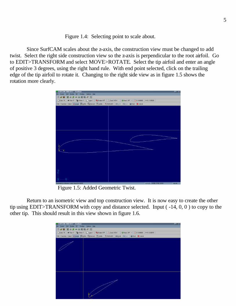
Figure 1.4: Selecting point to scale about. Since SurfCAM scales about the z-axis, the construction view must be changed to add twist. Select the right side construction view so the z-axis is perpendicular to the root airfoil. Go to EDIT>TRANSFORM and select MOVE>ROTATE. Select the tip airfoil and enter an angle of positive 3 degrees, using the right hand rule. With end point selected, click on the trailing edge of the tip airfoil to rotate it. Changing to the right side view as in figure 1.5 shows the rotation more clearly.
Figure 1.5: Added Geometric Twist. Return to an isometric view and top construction view. It is now easy to create the other tip using EDIT>TRANSFORM with copy and distance selected. Input ( -14, 0, 0 ) to copy to the other tip. This should result in this view shown in figure 1.6.

6
Wing Surfaces It is now time to create the wing surfaces. Surfaces are created using the airfoil contours but once created are independent of them. Select only two surfaces at a time to create the wing; selecting all three airfoils will create an unintended creature, usually a crescent. Go to CREATE>SURFACES and then select cross section and then section. Select the root airfoil and one of the tip airfoils, then select done. A surface joining them is created. Select section from the action menu and create the other side of the wing. The result is a wire frame wing. Before continuing, there are some issues to consider concerning surfaces. A brief scan of the menus reveals that SurfCAM does not have an undo button. If there is a problem with a created surface, the surface must be deleted from the edit menu and then recreated. This is possible because creating or deleting a surface does not affect the airfoil contours. It is easy to forget the delete tool is active so fortunately it is provided with an undo function. There are also yellow arrows attached to the surface; these denote which side of the surface is active but do not usually have an affect for this application. The SHADE button displays the surface as shaded but does not show the contours or UCS, as in figure 1.7.
Figure 1.7: Shaded view. To attach this wing to a fuselage requires a flat surface to be carved under the lower surface of the wing using a rectangular prism. Select CREATE>SURFACE and then PRIMITIVES and then CUBOID. Change construction view to front. To enter the side lengths, remember that height is the z-axis, width is the y-axis and length is the x-axis. Enter ( 2, -.25, -4) to create the box. Use EDIT>TRANSFORM>MOVE>DISTANCE to move the box one inch in the negative x-direction. Moving the box will create gaps that will distort the drawing; select the REPAINT icon, which looks like a paintbrush, to remedy this. The drawing should now be similar to figure 1.8 and is now ready to post to a file the router can read.

7
Figure 1.8: Completed wing. Posting Considerations Before posting, verify that the construction view is on top view and the coordinate system is set to view. There are several other limitations to keep in mind. The first is the orientation of the wing. The wing should be oriented so that the span is along the x-axis. If it is not use the transform>rotate command to make it so.
The second limitation is that the pieces of foam are only 2 inches thick. Carving the wing is also easiest if the origin is centered in the part. Using the EDIT>TRANSFORM>MOVE> DISTANCE>WITHIN function, center the construction UCS along each axis. Using the ANALYZE>LOCATION command, click on the trailing edge of the wing tip to find its y-axis location to center along the y-axis with formula 1.1.
504.22008.5
20
distancey Move −=−
=−
=−location
(1.1)
To center along the z-axis requires a different formula. Using the ANALYZE>DISTANCE command, find the height of the wing by clicking on the top of the tip and bottom of the box, making sure it is under two inches. Figure 1.9 demonstrates the use of the analyze functions.

8
Figure 1.9: Analyzing distance. Using EDIT>TRANSFORM>MOVE>DISTANCE>WITHIN function, move the entire wing assemblies down using formula 1.2. The ANALYZE>LOCATION tool can be used to verify that the wing is centered as in figure 1.10.
188.025.2875.0
origin below distance2
distance zdistance-z move −=
−−=
−−= (1.2)
Figure 1.10: Wing centered about origin.

9
Select NC>3 AXIS>PLANAR and change MULTI SELECT OFF to ON by clicking on it. Select the two wing surfaces and click DONE.
Figure 1.11: Defining the tool path.
A dialog box will come up concerning the tool path, as shown in figure 1.11. Here are the parameters of concern and what they should be set at. Tool Control Tool Set to tool #6, a ½ inch ball nose bit. Spindle speed 10,000 Feed rate 125 - 140 Plunge rate 65 Cut control Rapid plane 1.2 Step size 0.01 for rough cut, 0.005 for fine cut Cut waterfall ends Yes for top surface, No for bottom surface Click “apply” and then OK. Click the trailing edge of the wing tip to start, click the leading edge for direction, and then click on one of the wing surfaces. SurfCAM will begin tracing out a tool path, which must be allowed to complete for the entire part to be cut out. To speed up the process, hit the [TAB] key twice. Accept the path, which should follow the upper surface of the wing as shown in figure 1.12.

10
Figure 1.12: A tool path for the upper surface. Click on the operations manager button, which is circled in figure 1.12. the OPERATIONS MANAGER dialog box is pictured in figure1.13. Click on the element name THREE AXIS PLANER and rename it TOP. Also HIDE the tool path using the button with a drill bit next to a block. Click OK and change the view to axonometric and the construction view to bottom. It is interesting to note that the UCS rotates around the y-axis. This means that after the top surface is done, the block of foam must be flipped around the center chord line of the wing.
Figure 1.13: Operations Manager box Repeat the process of the top wing for the bottom, this time selecting the box and turning CUT WATERFALL ENDS to OFF. WATERFALL ENDS plunges the bit down at the leading

11
Exit this function and in the operations manager box click on the top name and in the top box on the right highlight CNC ROUTER and click the POST button. After a few seconds a text editor will come up with the code for the router. Save this on a 3¼-inch disk as “top.tap.” Repeat for the bottom and name it “low.tap.” Take this disk to the 3-axis router’s computer.

12
Other Helpful Commands
• CREATE>SURFACE>REVOLVE works much the same as in AutoCAD, creating a surface by revolving a line or arc around a defined axis.
• CREATE>SURFACE>FILLET creates a fillet where two points join. Using this greatly
increases file size and the time needed to create a tool path. Using a ½ inch drill bit will create a fillet where points are joined.
• EDIT>TRANSFORM>SCALE XYZ allows the user to scale the part differently along each axis.
This is particularly useful to extend wingspans by scaling just along the x-axis.
• CREATE>SURFACE>PRIMITIVE>PLANAR can also be used to create the mating surface. Additional Notes and Tips
• Elliptical wings can be created using the surface>mesh command. SurfCAM help contains a video file concerning this function.
• When generating a tool path, only the outermost surface will be carved. This means that
joining parts, such as in AutoCAD, is not necessary.
• There can be gaps between parts and the router will not try to make them. Appendix SurfCAM primers http://roger.ecn.purdue.edu/~wulf/Surfcam Airfoil Databases http://www.nasg.com/afdb/index-e.phtml http://www.moon-sun.com/cad/airfoil/foildata.htm