Surface w5 Sample
37
Advanced Surfaces Pro/ENGINEER Wildfire 5.0 Introduction to Surface Modeling Page 98 COPYRIGHT 2010 CADQUEST INC. Advanced Surfaces Introduction Several advanced surface types are available as listed below. Variable Section Sweep A surface is created by sweeping a single section along one or more trajectories. The section can vary along the trajectory. Boundary Blend A surface is created by selecting existing curves to define the boundaries of the geometry. Section to Surfaces Blend A surface is created by blending from an existing set of tangent surfaces to a sketched section. Surface to Surface Blend A surface is created by blending between two existing surfaces. The icons for the variable section sweep and the boundary blend are shown below. The other two surface types listed on this page do not have icons associated with them and must be created using the Insert, Advanced menu. Variable Section Sweep Boundary Blend Variable Section Sweep Boundary Blends
-
Upload
sathish-kumar -
Category
Documents
-
view
19 -
download
0
description
vb
Transcript of Surface w5 Sample
Advanced Surfaces Pro/ENGINEER Wildfire 5.0 Introduction to Surface Modeling
Page 98 COPYRIGHT 2010 CADQUEST INC.
Advanced Surfaces
Introduction
Several advanced surface types are available as listed below.
Variable Section Sweep A surface is created by sweeping a single section along one or more trajectories. The section can vary along the trajectory.
Boundary Blend A surface is created by selecting existing curves to define the boundaries of the geometry.
Section to Surfaces Blend A surface is created by blending from an existing set of tangent surfaces to a sketched section.
Surface to Surface Blend A surface is created by blending between two existing surfaces.
The icons for the variable section sweep and the boundary blend are shown below. The other two surface types listed on this page do not have icons associated with them and must be created using the Insert, Advanced menu.
Variable Section Sweep
Boundary Blend
Variable Section Sweep Boundary Blends
Pro/ENGINEER Wildfire 5.0 Introduction to Surface Modeling Advanced Surfaces
COPYRIGHT 2010 CADQUEST INC. Page 99
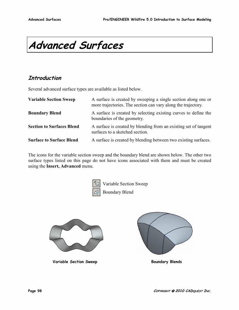
Variable Section Sweep
The Variable Section Sweep feature sweeps a single section along one or more trajectories. The section’s dimensions can vary as the section travels along the trajectories. The trajectories must be selected from existing datum curves. There are three types of variable section sweeps:
• Normal to Trajectory (see page 101). • Normal to Projection (see page 102). • Constant Normal Direction (see page 102).
Regardless of the type, every variable section sweep requires at least one ‘origin’ trajectory. In addition, each type has a special system parameter assigned to the trajectory, called trajpar (see page 103. When using this feature type, you have the choice of creating ‘surface’ or ‘solid’ geometry.
Several examples of variable section sweeps are shown below.
Advanced Surfaces Pro/ENGINEER Wildfire 5.0 Introduction to Surface Modeling
Page 100 COPYRIGHT 2010 CADQUEST INC.
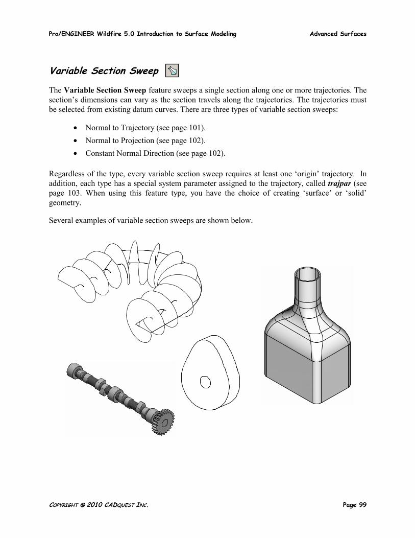
The Variable Section Sweep Tool
The Variable Section Sweep dashboard tool is used to create all types of variable section sweep features including solids, thins, surfaces, protrusions, and cuts. Pick Insert, Variable Section Sweep or pick the icon shown above. The Variable Section Sweep dashboard tool is shown below.
Use the right mouse button popup menu for shortcuts
Solid or Surface
Define the Sketch
Protrusion or cut
Create Thin
Make the section variable or constant in the Options panel
The References panel contains all the references for the feature
Set the section behavior here
Pro/ENGINEER Wildfire 5.0 Introduction to Surface Modeling Advanced Surfaces
COPYRIGHT 2010 CADQUEST INC. Page 101
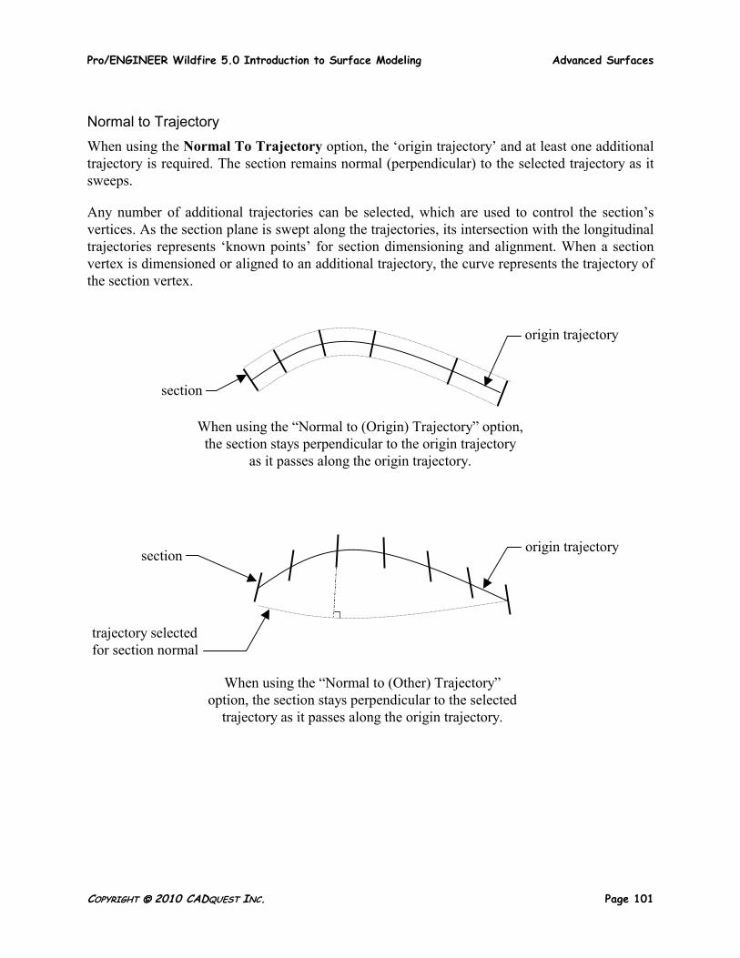
Normal to Trajectory
When using the Normal To Trajectory option, the ‘origin trajectory’ and at least one additional trajectory is required. The section remains normal (perpendicular) to the selected trajectory as it sweeps.
Any number of additional trajectories can be selected, which are used to control the section’s vertices. As the section plane is swept along the trajectories, its intersection with the longitudinal trajectories represents ‘known points’ for section dimensioning and alignment. When a section vertex is dimensioned or aligned to an additional trajectory, the curve represents the trajectory of the section vertex.
When using the “Normal to (Origin) Trajectory” option, the section stays perpendicular to the origin trajectory
as it passes along the origin trajectory.
origin trajectory
section
When using the “Normal to (Other) Trajectory” option, the section stays perpendicular to the selected
trajectory as it passes along the origin trajectory.
origin trajectory section
trajectory selected for section normal
Advanced Surfaces Pro/ENGINEER Wildfire 5.0 Introduction to Surface Modeling
Page 102 COPYRIGHT 2010 CADQUEST INC.
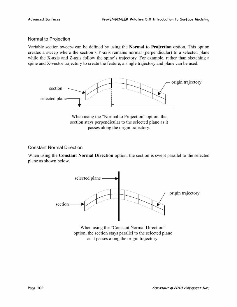
Normal to Projection
Variable section sweeps can be defined by using the Normal to Projection option. This option creates a sweep where the section’s Y-axis remains normal (perpendicular) to a selected plane while the X-axis and Z-axis follow the spine’s trajectory. For example, rather than sketching a spine and X-vector trajectory to create the feature, a single trajectory and plane can be used.
Constant Normal Direction
When using the Constant Normal Direction option, the section is swept parallel to the selected plane as shown below.
When using the “Normal to Projection” option, the section stays perpendicular to the selected plane as it
passes along the origin trajectory.
origin trajectory section
selected plane
When using the “Constant Normal Direction” option, the section stays parallel to the selected plane
as it passes along the origin trajectory.
origin trajectory
section
selected plane
Pro/ENGINEER Wildfire 5.0 Introduction to Surface Modeling Advanced Surfaces
COPYRIGHT 2010 CADQUEST INC. Page 103
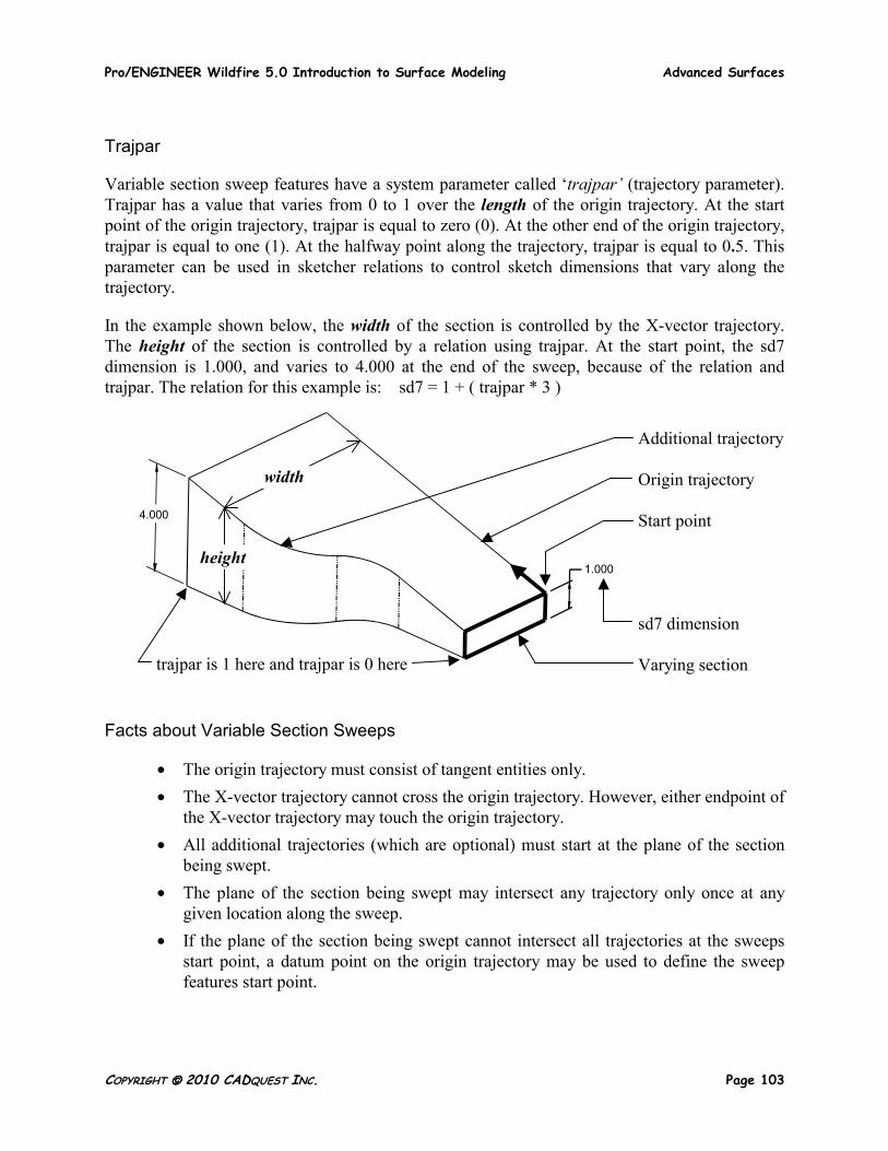
Trajpar
Variable section sweep features have a system parameter called ‘trajpar’ (trajectory parameter). Trajpar has a value that varies from 0 to 1 over the length of the origin trajectory. At the start point of the origin trajectory, trajpar is equal to zero (0). At the other end of the origin trajectory, trajpar is equal to one (1). At the halfway point along the trajectory, trajpar is equal to 0.5. This parameter can be used in sketcher relations to control sketch dimensions that vary along the trajectory.
In the example shown below, the width of the section is controlled by the X-vector trajectory. The height of the section is controlled by a relation using trajpar. At the start point, the sd7 dimension is 1.000, and varies to 4.000 at the end of the sweep, because of the relation and trajpar. The relation for this example is: sd7 = 1 + ( trajpar * 3 )
Facts about Variable Section Sweeps
• The origin trajectory must consist of tangent entities only. • The X-vector trajectory cannot cross the origin trajectory. However, either endpoint of
the X-vector trajectory may touch the origin trajectory. • All additional trajectories (which are optional) must start at the plane of the section
being swept. • The plane of the section being swept may intersect any trajectory only once at any
given location along the sweep. • If the plane of the section being swept cannot intersect all trajectories at the sweeps
start point, a datum point on the origin trajectory may be used to define the sweep features start point.
Additional trajectory Origin trajectory Start point sd7 dimension Varying section
trajpar is 1 here and trajpar is 0 here
width
height
4.000
1.000
Advanced Surfaces Pro/ENGINEER Wildfire 5.0 Introduction to Surface Modeling
Page 104 COPYRIGHT 2010 CADQUEST INC.
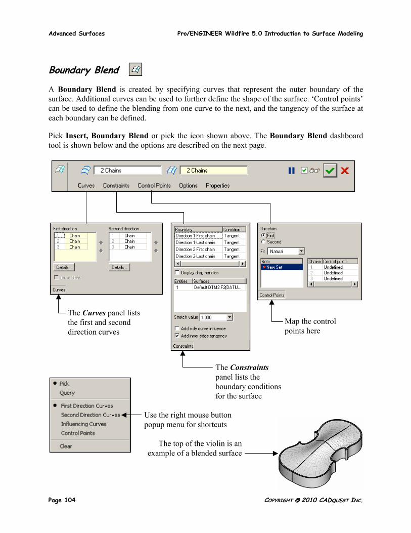
Boundary Blend
A Boundary Blend is created by specifying curves that represent the outer boundary of the surface. Additional curves can be used to further define the shape of the surface. ‘Control points’ can be used to define the blending from one curve to the next, and the tangency of the surface at each boundary can be defined.
Pick Insert, Boundary Blend or pick the icon shown above. The Boundary Blend dashboard tool is shown below and the options are described on the next page.
Use the right mouse button popup menu for shortcuts
The top of the violin is an example of a blended surface
The Curves panel lists the first and second direction curves
Map the control points here
The Constraints panel lists the boundary conditions for the surface
Pro/ENGINEER Wildfire 5.0 Introduction to Surface Modeling Advanced Surfaces
COPYRIGHT 2010 CADQUEST INC. Page 105
Boundary Blend (continued)
The Boundary Blend feature has many options as listed below.
First Direction Curves The curves or edges that define the boundary of the surface in the first direction.
Second Direction Curves Additional curves or edges that define the boundary of the surface in the second direction. Second direction curves are optional for some blended surfaces.
Side Curve Influence For surfaces with ‘first direction curves’ only, the system changes the resulting surface by examining the curves that are adjacent to the selected boundary curves.
Influencing Curves Additional curves that define an approximate boundary for the surface. This is not related to ‘side curve influence’.
Control Points Used to control the internal tangent edges of the blended surface.
Boundary Conditions One of the following four choices defines the surface’s topology at each of the selected boundary curve.
Free No tangency condition is set.
Tangent The surface is tangent to a selected reference entity.
Normal The surface is perpendicular to a selected reference entity.
Curvature The surface has continuous curvature (C2) to a selected reference entity.
Advanced Surfaces Pro/ENGINEER Wildfire 5.0 Introduction to Surface Modeling
Page 106 COPYRIGHT 2010 CADQUEST INC.
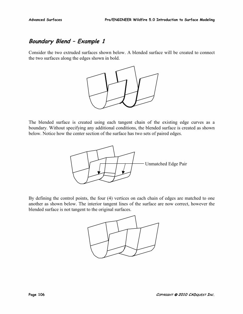
Boundary Blend – Example 1
Consider the two extruded surfaces shown below. A blended surface will be created to connect the two surfaces along the edges shown in bold.
The blended surface is created using each tangent chain of the existing edge curves as a boundary. Without specifying any additional conditions, the blended surface is created as shown below. Notice how the center section of the surface has two sets of paired edges.
By defining the control points, the four (4) vertices on each chain of edges are matched to one another as shown below. The interior tangent lines of the surface are now correct, however the blended surface is not tangent to the original surfaces.
Unmatched Edge Pair
Pro/ENGINEER Wildfire 5.0 Introduction to Surface Modeling Advanced Surfaces
COPYRIGHT 2010 CADQUEST INC. Page 107
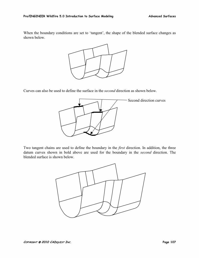
When the boundary conditions are set to ‘tangent’, the shape of the blended surface changes as shown below.
Curves can also be used to define the surface in the second direction as shown below.
Two tangent chains are used to define the boundary in the first direction. In addition, the three datum curves shown in bold above are used for the boundary in the second direction. The blended surface is shown below.
Second direction curves
Advanced Surfaces Pro/ENGINEER Wildfire 5.0 Introduction to Surface Modeling
Page 108 COPYRIGHT 2010 CADQUEST INC.
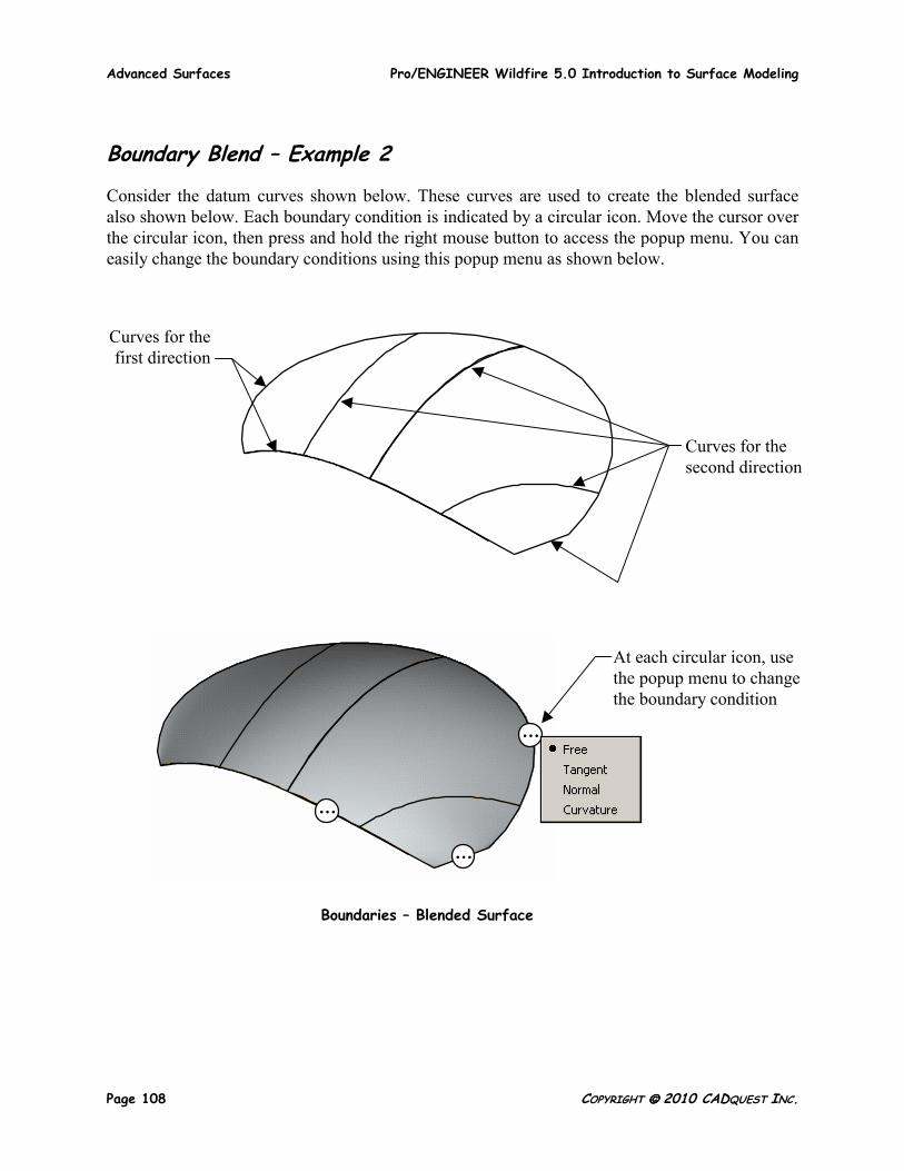
Boundary Blend – Example 2
Consider the datum curves shown below. These curves are used to create the blended surface also shown below. Each boundary condition is indicated by a circular icon. Move the cursor over the circular icon, then press and hold the right mouse button to access the popup menu. You can easily change the boundary conditions using this popup menu as shown below.
Curves for the second direction
Curves for the first direction
Boundaries – Blended Surface
…
…
…
At each circular icon, use the popup menu to change the boundary condition
Pro/ENGINEER Wildfire 5.0 Introduction to Surface Modeling Advanced Surfaces
COPYRIGHT 2010 CADQUEST INC. Page 109
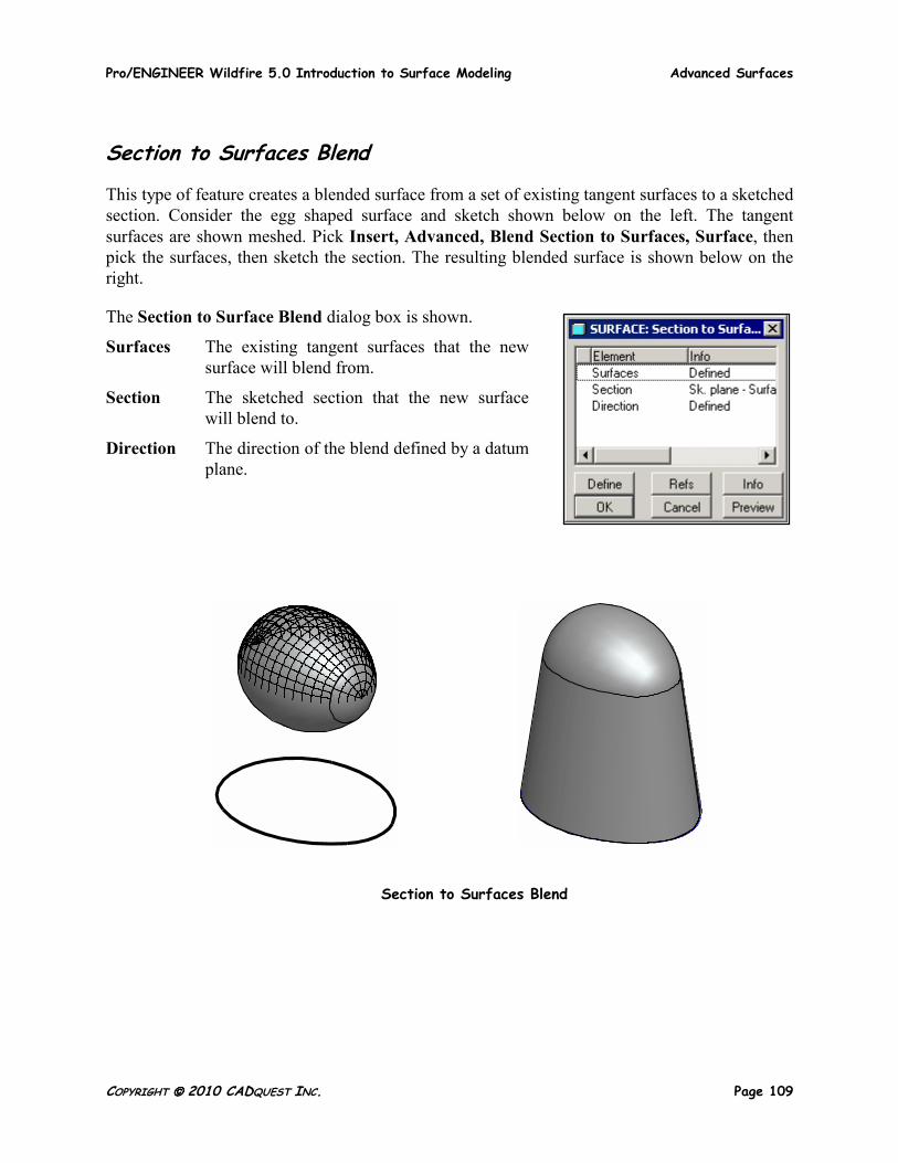
Section to Surfaces Blend
This type of feature creates a blended surface from a set of existing tangent surfaces to a sketched section. Consider the egg shaped surface and sketch shown below on the left. The tangent surfaces are shown meshed. Pick Insert, Advanced, Blend Section to Surfaces, Surface, then pick the surfaces, then sketch the section. The resulting blended surface is shown below on the right.
The Section to Surface Blend dialog box is shown.
Surfaces The existing tangent surfaces that the new surface will blend from.
Section The sketched section that the new surface will blend to.
Direction The direction of the blend defined by a datum plane.
Section to Surfaces Blend
Advanced Surfaces Pro/ENGINEER Wildfire 5.0 Introduction to Surface Modeling
Page 110 COPYRIGHT 2010 CADQUEST INC.
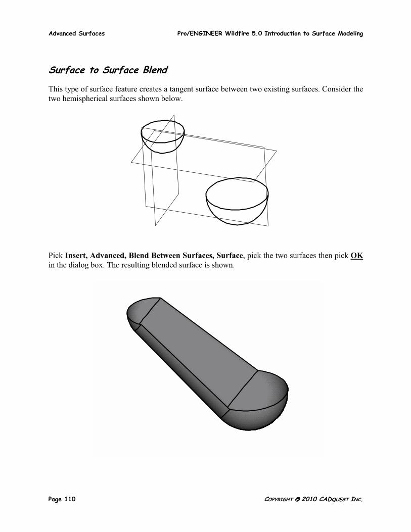
Surface to Surface Blend
This type of surface feature creates a tangent surface between two existing surfaces. Consider the two hemispherical surfaces shown below.
Pick Insert, Advanced, Blend Between Surfaces, Surface, pick the two surfaces then pick OK in the dialog box. The resulting blended surface is shown.
Pro/ENGINEER Wildfire 5.0 Introduction to Surface Modeling Advanced Surfaces
COPYRIGHT 2010 CADQUEST INC. Page 111
EXERCISE 3 – ADVANCED SURFACES
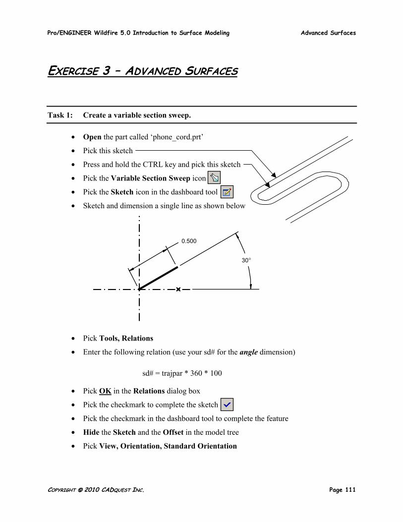
Task 1: Create a variable section sweep.
• Open the part called ‘phone_cord.prt’
• Pick this sketch
• Press and hold the CTRL key and pick this sketch
• Pick the Variable Section Sweep icon
• Pick the Sketch icon in the dashboard tool
• Sketch and dimension a single line as shown below
• Pick Tools, Relations
• Enter the following relation (use your sd# for the angle dimension)
sd# = trajpar * 360 * 100
• Pick OK in the Relations dialog box
• Pick the checkmark to complete the sketch
• Pick the checkmark in the dashboard tool to complete the feature
• Hide the Sketch and the Offset in the model tree
• Pick View, Orientation, Standard Orientation
30°
0.500
Advanced Surfaces Pro/ENGINEER Wildfire 5.0 Introduction to Surface Modeling
Page 112 COPYRIGHT 2010 CADQUEST INC.
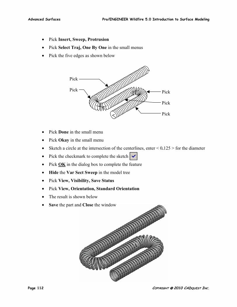
• Pick Insert, Sweep, Protrusion
• Pick Select Traj, One By One in the small menus
• Pick the five edges as shown below
• Pick Done in the small menu
• Pick Okay in the small menu
• Sketch a circle at the intersection of the centerlines, enter < 0.125 > for the diameter
• Pick the checkmark to complete the sketch
• Pick OK in the dialog box to complete the feature
• Hide the Var Sect Sweep in the model tree
• Pick View, Visibility, Save Status
• Pick View, Orientation, Standard Orientation
• The result is shown below
• Save the part and Close the window
Pick Pick Pick
Pick Pick
Pro/ENGINEER Wildfire 5.0 Introduction to Surface Modeling Advanced Surfaces
COPYRIGHT 2010 CADQUEST INC. Page 113
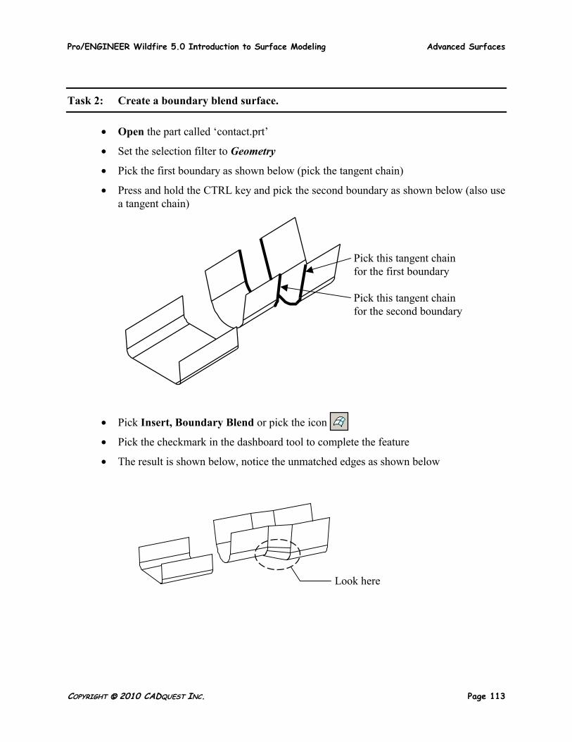
Task 2: Create a boundary blend surface.
• Open the part called ‘contact.prt’
• Set the selection filter to Geometry
• Pick the first boundary as shown below (pick the tangent chain)
• Press and hold the CTRL key and pick the second boundary as shown below (also use a tangent chain)
• Pick Insert, Boundary Blend or pick the icon
• Pick the checkmark in the dashboard tool to complete the feature
• The result is shown below, notice the unmatched edges as shown below
Pick this tangent chain for the first boundary Pick this tangent chain for the second boundary
Look here
Advanced Surfaces Pro/ENGINEER Wildfire 5.0 Introduction to Surface Modeling
Page 114 COPYRIGHT 2010 CADQUEST INC.
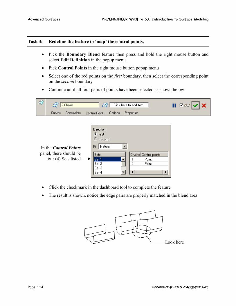
Task 3: Redefine the feature to ‘map’ the control points.
• Pick the Boundary Blend feature then press and hold the right mouse button and select Edit Definition in the popup menu
• Pick Control Points in the right mouse button popup menu
• Select one of the red points on the first boundary, then select the corresponding point on the second boundary
• Continue until all four pairs of points have been selected as shown below
• Click the checkmark in the dashboard tool to complete the feature
• The result is shown, notice the edge pairs are properly matched in the blend area
Look here
In the Control Pointspanel, there should be
four (4) Sets listed
Pro/ENGINEER Wildfire 5.0 Introduction to Surface Modeling Advanced Surfaces
COPYRIGHT 2010 CADQUEST INC. Page 115
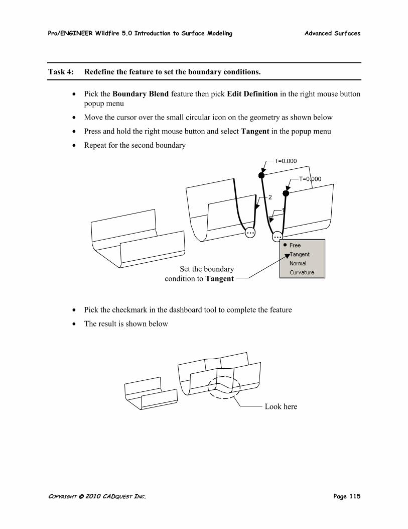
Task 4: Redefine the feature to set the boundary conditions.
• Pick the Boundary Blend feature then pick Edit Definition in the right mouse button popup menu
• Move the cursor over the small circular icon on the geometry as shown below
• Press and hold the right mouse button and select Tangent in the popup menu
• Repeat for the second boundary
• Pick the checkmark in the dashboard tool to complete the feature
• The result is shown below
Set the boundary condition to Tangent
… …
T=0.000
T=0.000
1
2
Look here
Advanced Surfaces Pro/ENGINEER Wildfire 5.0 Introduction to Surface Modeling
Page 116 COPYRIGHT 2010 CADQUEST INC.
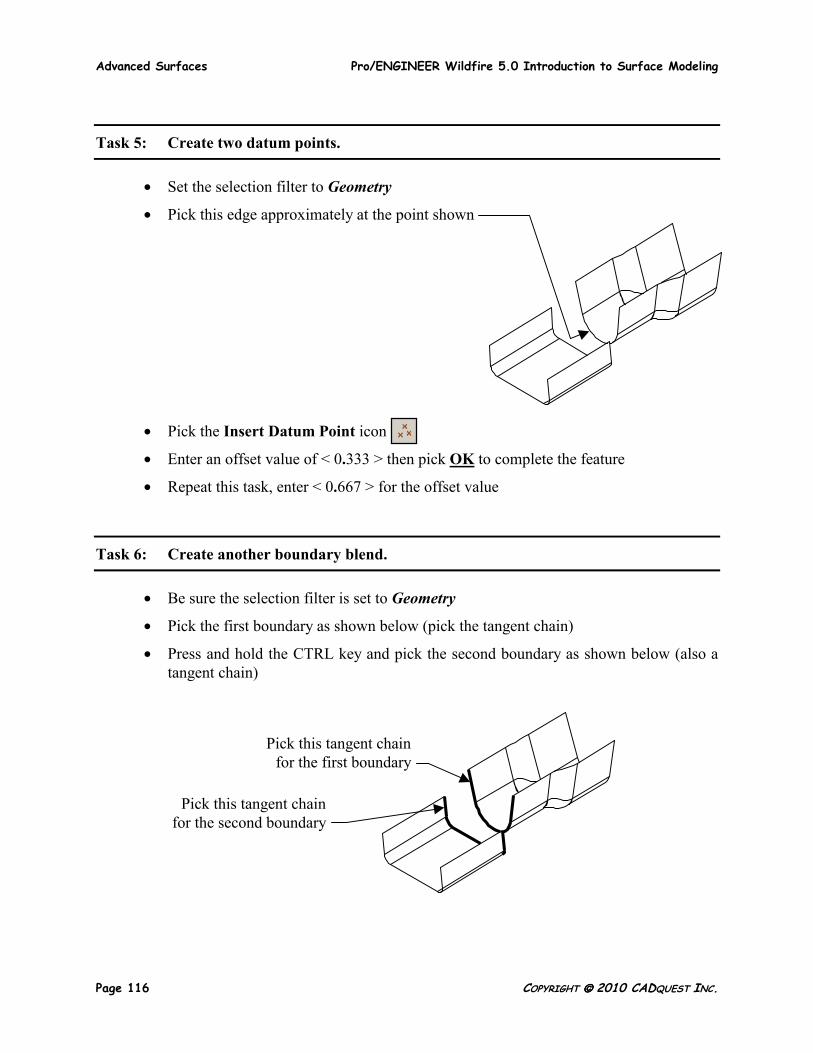
Task 5: Create two datum points.
• Set the selection filter to Geometry
• Pick this edge approximately at the point shown
• Pick the Insert Datum Point icon
• Enter an offset value of < 0.333 > then pick OK to complete the feature
• Repeat this task, enter < 0.667 > for the offset value
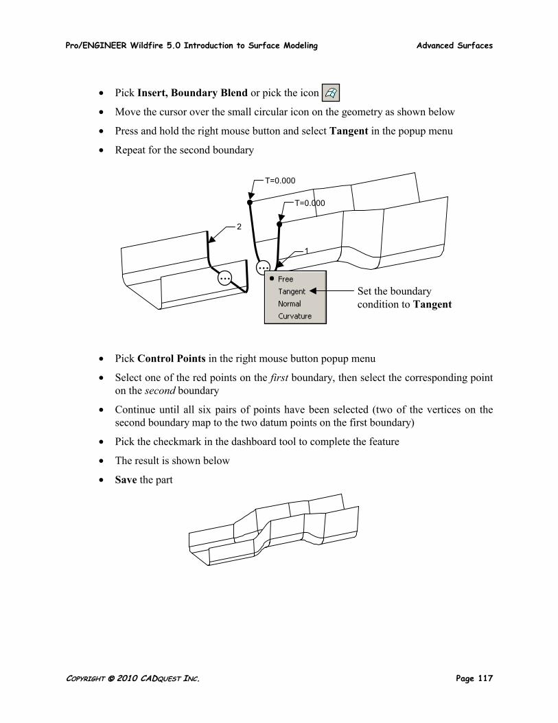
Task 6: Create another boundary blend.
• Be sure the selection filter is set to Geometry
• Pick the first boundary as shown below (pick the tangent chain)
• Press and hold the CTRL key and pick the second boundary as shown below (also a tangent chain)
Pick this tangent chain for the first boundary
Pick this tangent chain for the second boundary
Pro/ENGINEER Wildfire 5.0 Introduction to Surface Modeling Advanced Surfaces
COPYRIGHT 2010 CADQUEST INC. Page 117
• Pick Insert, Boundary Blend or pick the icon
• Move the cursor over the small circular icon on the geometry as shown below
• Press and hold the right mouse button and select Tangent in the popup menu
• Repeat for the second boundary
• Pick Control Points in the right mouse button popup menu
• Select one of the red points on the first boundary, then select the corresponding point on the second boundary
• Continue until all six pairs of points have been selected (two of the vertices on the second boundary map to the two datum points on the first boundary)
• Pick the checkmark in the dashboard tool to complete the feature
• The result is shown below
• Save the part
… …
T=0.000
1
2
T=0.000
Set the boundary condition to Tangent
Advanced Surfaces Pro/ENGINEER Wildfire 5.0 Introduction to Surface Modeling
Page 118 COPYRIGHT 2010 CADQUEST INC.
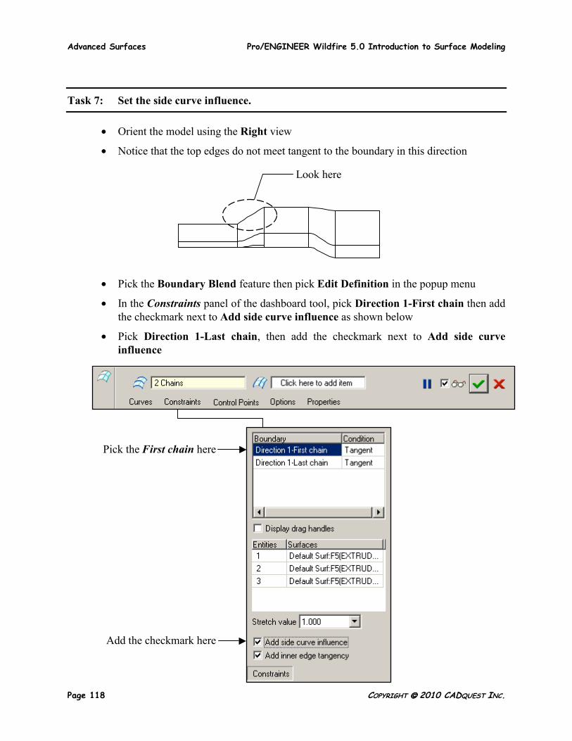
Task 7: Set the side curve influence.
• Orient the model using the Right view
• Notice that the top edges do not meet tangent to the boundary in this direction
• Pick the Boundary Blend feature then pick Edit Definition in the popup menu
• In the Constraints panel of the dashboard tool, pick Direction 1-First chain then add the checkmark next to Add side curve influence as shown below
• Pick Direction 1-Last chain, then add the checkmark next to Add side curve influence
Look here
Pick the First chain here
Add the checkmark here
Pro/ENGINEER Wildfire 5.0 Introduction to Surface Modeling Advanced Surfaces
COPYRIGHT 2010 CADQUEST INC. Page 119
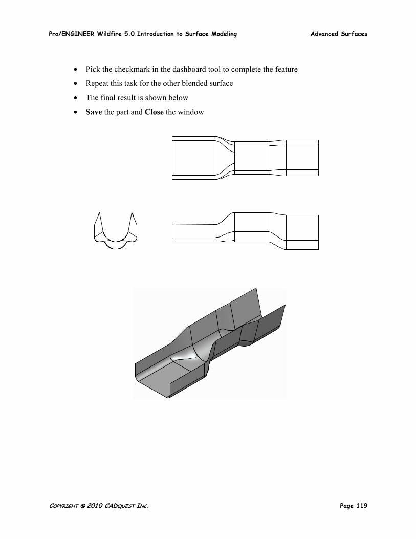
• Pick the checkmark in the dashboard tool to complete the feature
• Repeat this task for the other blended surface
• The final result is shown below
• Save the part and Close the window
Advanced Surfaces Pro/ENGINEER Wildfire 5.0 Introduction to Surface Modeling
Page 120 COPYRIGHT 2010 CADQUEST INC.
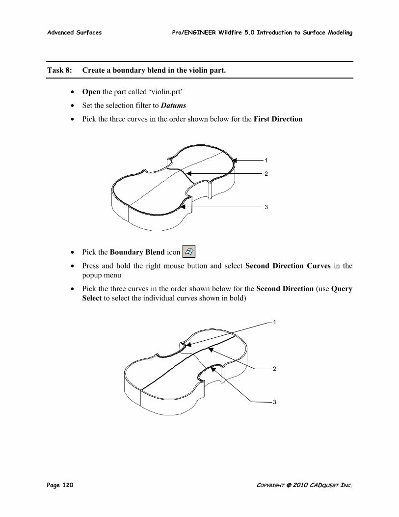
Task 8: Create a boundary blend in the violin part.
• Open the part called ‘violin.prt’
• Set the selection filter to Datums
• Pick the three curves in the order shown below for the First Direction
• Pick the Boundary Blend icon
• Press and hold the right mouse button and select Second Direction Curves in the popup menu
• Pick the three curves in the order shown below for the Second Direction (use Query Select to select the individual curves shown in bold)
1 2 3
1 2 3
Pro/ENGINEER Wildfire 5.0 Introduction to Surface Modeling Advanced Surfaces
COPYRIGHT 2010 CADQUEST INC. Page 121
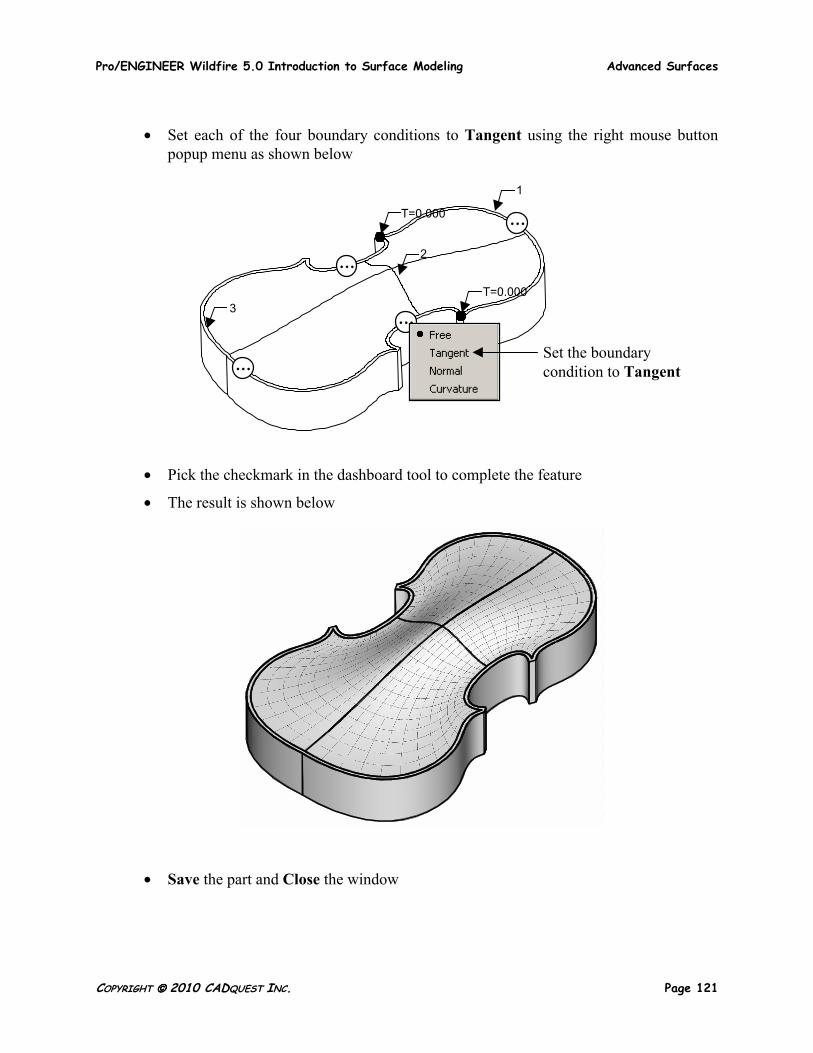
• Set each of the four boundary conditions to Tangent using the right mouse button popup menu as shown below
• Pick the checkmark in the dashboard tool to complete the feature
• The result is shown below
• Save the part and Close the window
…
…
…
… 3
2
1
T=0.000
T=0.000
Set the boundary condition to Tangent
Advanced Surfaces Pro/ENGINEER Wildfire 5.0 Introduction to Surface Modeling
Page 122 COPYRIGHT 2010 CADQUEST INC.
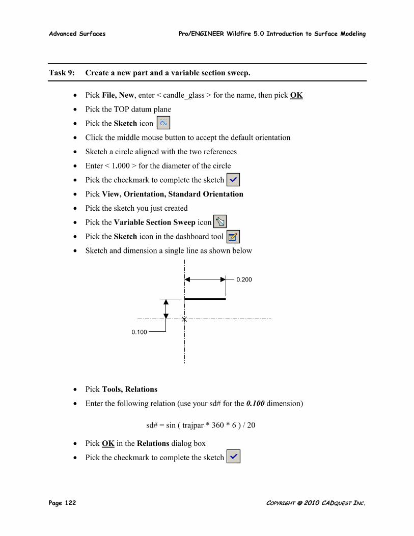
Task 9: Create a new part and a variable section sweep.
• Pick File, New, enter < candle_glass > for the name, then pick OK
• Pick the TOP datum plane
• Pick the Sketch icon
• Click the middle mouse button to accept the default orientation
• Sketch a circle aligned with the two references
• Enter < 1.000 > for the diameter of the circle
• Pick the checkmark to complete the sketch
• Pick View, Orientation, Standard Orientation
• Pick the sketch you just created
• Pick the Variable Section Sweep icon
• Pick the Sketch icon in the dashboard tool
• Sketch and dimension a single line as shown below
• Pick Tools, Relations
• Enter the following relation (use your sd# for the 0.100 dimension)
sd# = sin ( trajpar * 360 * 6 ) / 20
• Pick OK in the Relations dialog box
• Pick the checkmark to complete the sketch
0.200
0.100
Pro/ENGINEER Wildfire 5.0 Introduction to Surface Modeling Advanced Surfaces
COPYRIGHT 2010 CADQUEST INC. Page 123
• Pick the checkmark in the dashboard tool to complete the feature
• Hide the Sketch in the model tree
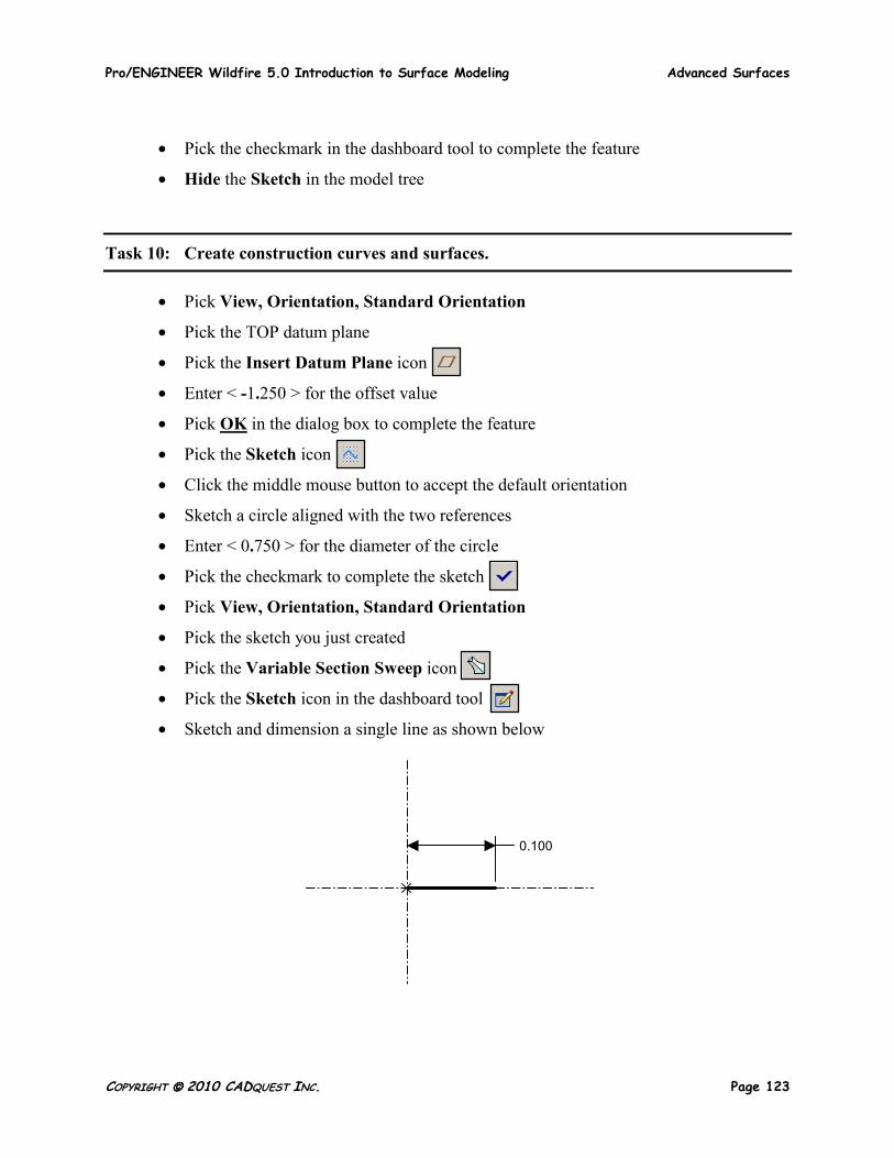
Task 10: Create construction curves and surfaces.
• Pick View, Orientation, Standard Orientation
• Pick the TOP datum plane
• Pick the Insert Datum Plane icon
• Enter < -1.250 > for the offset value
• Pick OK in the dialog box to complete the feature
• Pick the Sketch icon
• Click the middle mouse button to accept the default orientation
• Sketch a circle aligned with the two references
• Enter < 0.750 > for the diameter of the circle
• Pick the checkmark to complete the sketch
• Pick View, Orientation, Standard Orientation
• Pick the sketch you just created
• Pick the Variable Section Sweep icon
• Pick the Sketch icon in the dashboard tool
• Sketch and dimension a single line as shown below
0.100
Advanced Surfaces Pro/ENGINEER Wildfire 5.0 Introduction to Surface Modeling
Page 124 COPYRIGHT 2010 CADQUEST INC.
• Pick Tools, Relations
• Enter the following relation (use your sd# for the 0.100 dimension)
sd# = 0.030 + ( sin ( trajpar * 360 * 6 ) / 50 )
• Pick OK in the Relations dialog box
• Pick the checkmark to complete the sketch
• Pick the checkmark in the dashboard tool to complete the feature
• Pick View, Orientation, Standard Orientation
• Hide the Sketch in the model tree
• Save the part
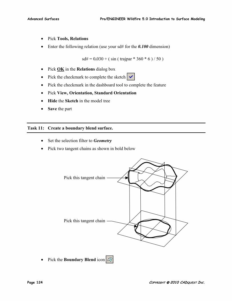
Task 11: Create a boundary blend surface.
• Set the selection filter to Geometry
• Pick two tangent chains as shown in bold below
• Pick the Boundary Blend icon
Pick this tangent chain Pick this tangent chain

Pro/ENGINEER Wildfire 5.0 Introduction to Surface Modeling Advanced Surfaces
COPYRIGHT 2010 CADQUEST INC. Page 125
• Pick the checkmark in the dashboard tool to complete the feature
• Hide both Var Sect Sweep features in the model tree
• Pick View, Visibility, Save Status
• Pick View, Orientation, Standard Orientation
• The result is shown below
• Save the part and Close the window

Advanced Surfaces Pro/ENGINEER Wildfire 5.0 Introduction to Surface Modeling
Page 126 COPYRIGHT 2010 CADQUEST INC.
Task 12: Create a boundary blend surface.
• Open the part called ‘container.prt’
• Hide the extruded surface in the model tree
• Hide the flat surface in the model tree
• Pick the two curves as shown below for the First Direction
• Pick the Boundary Blend icon
• Press and hold the right mouse button and select Second Direction Curves in the popup menu
• Pick the three curves as shown below for the Second Direction
• Press and hold the right mouse button and select Control Points in the popup menu
• Select one of the red points on the first boundary, then select the corresponding point on the second boundary
1
2
1
2
3
Pro/ENGINEER Wildfire 5.0 Introduction to Surface Modeling Advanced Surfaces
COPYRIGHT 2010 CADQUEST INC. Page 127
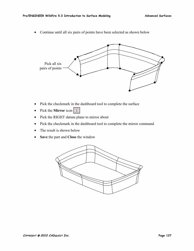
• Continue until all six pairs of points have been selected as shown below
• Pick the checkmark in the dashboard tool to complete the surface
• Pick the Mirror icon
• Pick the RIGHT datum plane to mirror about
• Pick the checkmark in the dashboard tool to complete the mirror command
• The result is shown below
• Save the part and Close the window
Pick all six pairs of points
Advanced Surfaces Pro/ENGINEER Wildfire 5.0 Introduction to Surface Modeling
Page 128 COPYRIGHT 2010 CADQUEST INC.
Task 13: Create four boundary blend surfaces.
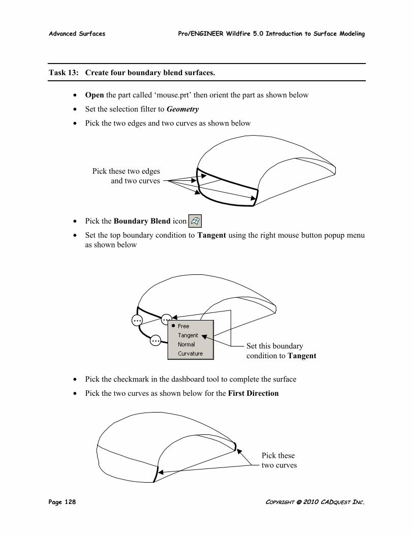
• Open the part called ‘mouse.prt’ then orient the part as shown below
• Set the selection filter to Geometry
• Pick the two edges and two curves as shown below
• Pick the Boundary Blend icon
• Set the top boundary condition to Tangent using the right mouse button popup menu as shown below
• Pick the checkmark in the dashboard tool to complete the surface
• Pick the two curves as shown below for the First Direction
… …
… Set this boundary condition to Tangent
Pick these two edges and two curves
Pick these two curves
Pro/ENGINEER Wildfire 5.0 Introduction to Surface Modeling Advanced Surfaces
COPYRIGHT 2010 CADQUEST INC. Page 129
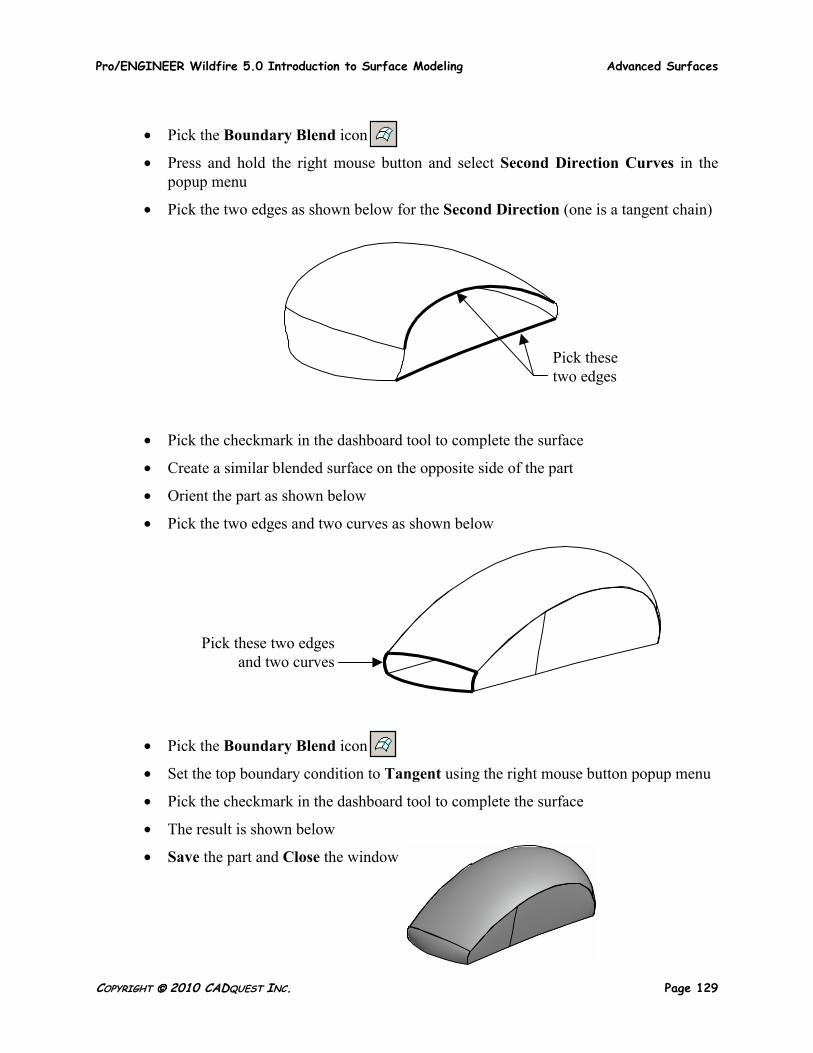
• Pick the Boundary Blend icon
• Press and hold the right mouse button and select Second Direction Curves in the popup menu
• Pick the two edges as shown below for the Second Direction (one is a tangent chain)
• Pick the checkmark in the dashboard tool to complete the surface
• Create a similar blended surface on the opposite side of the part
• Orient the part as shown below
• Pick the two edges and two curves as shown below
• Pick the Boundary Blend icon
• Set the top boundary condition to Tangent using the right mouse button popup menu
• Pick the checkmark in the dashboard tool to complete the surface
• The result is shown below
• Save the part and Close the window
Pick these two edges
Pick these two edges and two curves
Advanced Surfaces Pro/ENGINEER Wildfire 5.0 Introduction to Surface Modeling
Page 130 COPYRIGHT 2010 CADQUEST INC.
Task 14: Create four boundary blend surfaces.
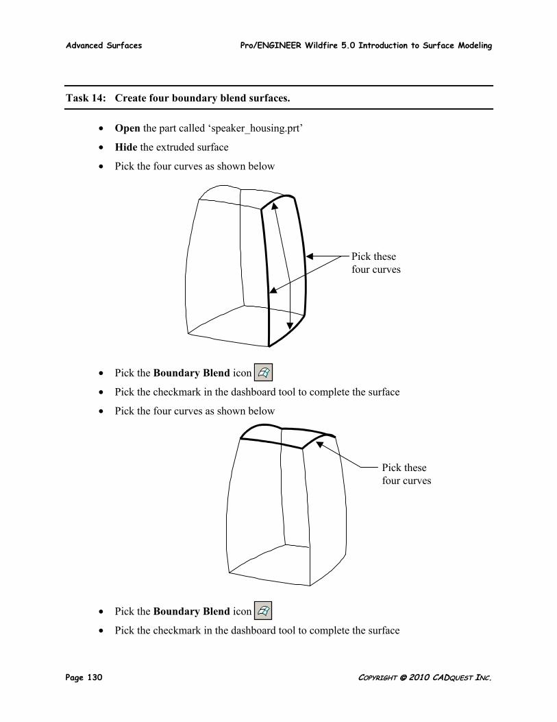
• Open the part called ‘speaker_housing.prt’
• Hide the extruded surface
• Pick the four curves as shown below
• Pick the Boundary Blend icon
• Pick the checkmark in the dashboard tool to complete the surface
• Pick the four curves as shown below
• Pick the Boundary Blend icon
• Pick the checkmark in the dashboard tool to complete the surface
Pick these four curves
Pick these four curves
Pro/ENGINEER Wildfire 5.0 Introduction to Surface Modeling Advanced Surfaces
COPYRIGHT 2010 CADQUEST INC. Page 131
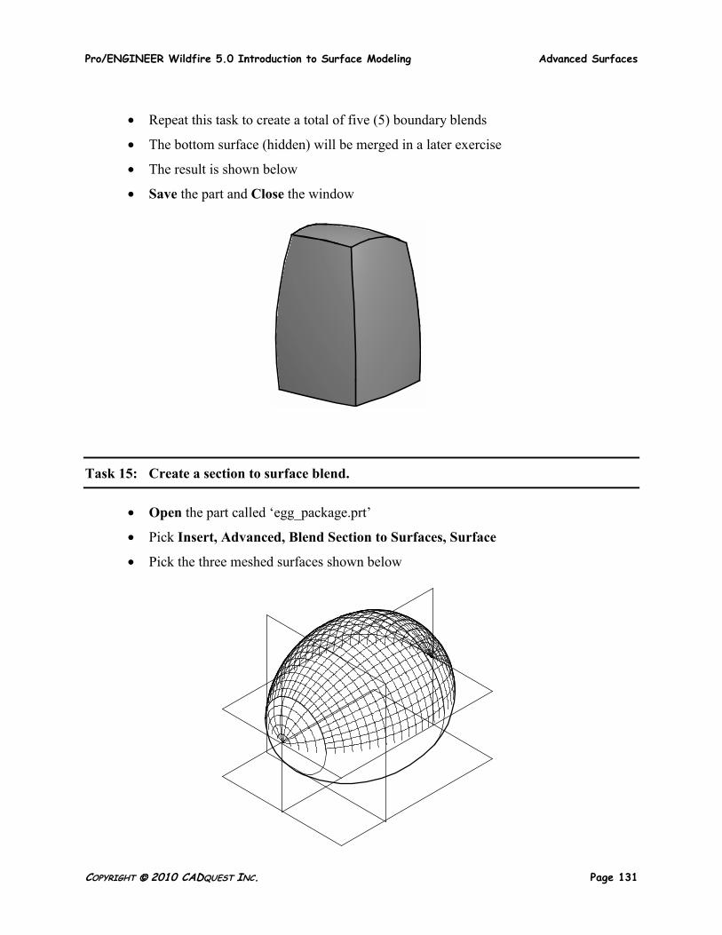
• Repeat this task to create a total of five (5) boundary blends
• The bottom surface (hidden) will be merged in a later exercise
• The result is shown below
• Save the part and Close the window
Task 15: Create a section to surface blend.
• Open the part called ‘egg_package.prt’
• Pick Insert, Advanced, Blend Section to Surfaces, Surface
• Pick the three meshed surfaces shown below
Advanced Surfaces Pro/ENGINEER Wildfire 5.0 Introduction to Surface Modeling
Page 132 COPYRIGHT 2010 CADQUEST INC.
• Pick OK in the Select dialog box
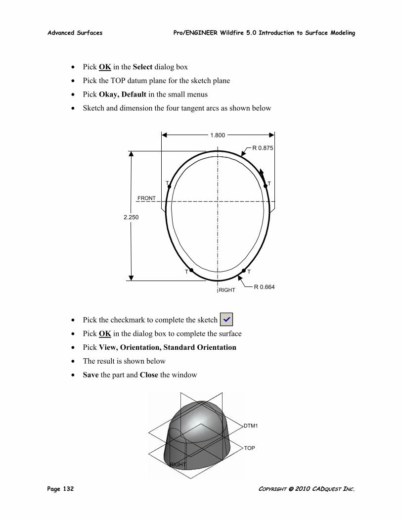
• Pick the TOP datum plane for the sketch plane
• Pick Okay, Default in the small menus
• Sketch and dimension the four tangent arcs as shown below
• Pick the checkmark to complete the sketch
• Pick OK in the dialog box to complete the surface
• Pick View, Orientation, Standard Orientation
• The result is shown below
• Save the part and Close the window
DTM1
TOP
RIGHT
1.800
R 0.875
2.250
R 0.664 RIGHT
FRONT
T T
T T
Pro/ENGINEER Wildfire 5.0 Introduction to Surface Modeling Advanced Surfaces
COPYRIGHT 2010 CADQUEST INC. Page 133
Task 16: Create boundary blend surfaces.
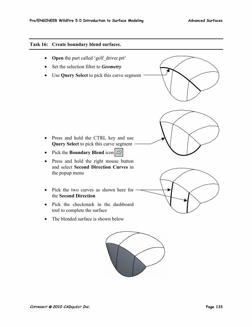
• Open the part called ‘golf_driver.prt’
• Set the selection filter to Geometry
• Use Query Select to pick this curve segment
• Press and hold the CTRL key and use Query Select to pick this curve segment
• Pick the Boundary Blend icon
• Press and hold the right mouse button and select Second Direction Curves in the popup menu
• Pick the two curves as shown here for the Second Direction
• Pick the checkmark in the dashboard tool to complete the surface
• The blended surface is shown below
Advanced Surfaces Pro/ENGINEER Wildfire 5.0 Introduction to Surface Modeling
Page 134 COPYRIGHT 2010 CADQUEST INC.
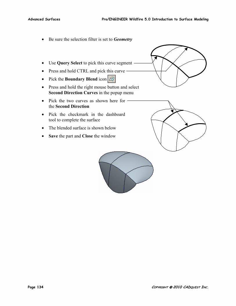
• Be sure the selection filter is set to Geometry
• Use Query Select to pick this curve segment
• Press and hold CTRL and pick this curve
• Pick the Boundary Blend icon
• Press and hold the right mouse button and select Second Direction Curves in the popup menu
• Pick the two curves as shown here for the Second Direction
• Pick the checkmark in the dashboard tool to complete the surface
• The blended surface is shown below
• Save the part and Close the window


![W5 abdomen[1]](https://static.fdocuments.in/doc/165x107/577d2e9e1a28ab4e1eaf8a9e/w5-abdomen1.jpg)