Surface Mount Thin-Film Filters
4
Notes A. Performance and quality attributes and conditions not expressly stated in this specification document are intended to be excluded and do not form a part of this specification document. B. Electrical specifications and performance data contained in this specification document are based on Mini-Circuit’s applicable established test performance criteria and measurement instructions. C. The parts covered by this specification document are subject to Mini-Circuits standard limited warranty and terms and conditions (collectively, “Standard Terms”); Purchasers of this part are entitled to the rights and benefits contained therein. For a full statement of the Standard Terms and the exclusive rights and remedies thereunder, please visit Mini-Circuits’ website at www.minicircuits.com/MCLStore/terms.jsp Mini-Circuits ® www.minicircuits.com P.O. Box 350166, Brooklyn, NY 11235-0003 (718) 934-4500 [email protected] Page 1 of 4 The Big Deal • Low passband insertion loss • High rejection • Good power handling • Temperature stability -55°C to 125°C • High repeatability • RoHS complaint • Small size Product Overview Mini-Circuits’ Surface Mount Thin-Film filters offer low insertion loss and high rejection realized via Thin-Film on Alumina substrate, using a sputtering process that can guarantee a enhanced Q and repeatable performance. Low pass, high pass and bandpass surface mount thin-film designs can be realized with this technology. Using thin-film manufacturing, we can guarantee repeatability on large batches of filters. Thin-film filters are small in size with high-quality, precise machining for applications where size is critical. Key Features 50Ω DC to 40 GHz Feature Advantages Low insertion loss High Q material and sputtering process results in lower insertion loss, better SNR is obtained. Fast roll-off (steeper skirts) High selectivity results in better adjacent channel rejection and dynamic range Wider stopband Wide spur-free stopband results in better adjacent channel rejection and dynamic range Temperature stability Very minimal change in electrical performance across temperature makes these filters suitable for a wide range of operating conditions. Small Size Various design techniques are employed to realize small size. Surface Mount Thin-Film Filters
Transcript of Surface Mount Thin-Film Filters

NotesA. Performance and quality attributes and conditions not expressly stated in this specification document are intended to be excluded and do not form a part of this specification document. B. Electrical specifications and performance data contained in this specification document are based on Mini-Circuit’s applicable established test performance criteria and measurement instructions. C. The parts covered by this specification document are subject to Mini-Circuits standard limited warranty and terms and conditions (collectively, “Standard Terms”); Purchasers of this part are entitled to the rights and benefits contained therein. For a full statement of the Standard Terms and the exclusive rights and remedies thereunder, please visit Mini-Circuits’ website at www.minicircuits.com/MCLStore/terms.jsp
Mini-Circuits®
www.minicircuits.com P.O. Box 350166, Brooklyn, NY 11235-0003 (718) 934-4500 [email protected] Page 1 of 4
The Big Deal• Low passband insertion loss• High rejection• Good power handling• Temperature stability -55°C to 125°C • High repeatability• RoHS complaint • Small size
Product OverviewMini-Circuits’ Surface Mount Thin-Film filters offer low insertion loss and high rejection realized via Thin-Film on Alumina substrate, using a sputtering process that can guarantee a enhanced Q and repeatable performance.
Low pass, high pass and bandpass surface mount thin-film designs can be realized with this technology. Using thin-film manufacturing, we can guarantee repeatability on large batches of filters. Thin-film filters are small in size with high-quality, precise machining for applications where size is critical.
Key Features
50Ω DC to 40 GHz
Feature Advantages
Low insertion loss High Q material and sputtering process results in lower insertion loss, better SNR is obtained.
Fast roll-off (steeper skirts) High selectivity results in better adjacent channel rejection and dynamic range
Wider stopband Wide spur-free stopband results in better adjacent channel rejection and dynamic range
Temperature stability Very minimal change in electrical performance across temperature makes these filters suitable for a wide range of operating conditions.
Small Size Various design techniques are employed to realize small size.
Surface Mount Thin-Film Filters
NotesA. Performance and quality attributes and conditions not expressly stated in this specification document are intended to be excluded and do not form a part of this specification document. B. Electrical specifications and performance data contained in this specification document are based on Mini-Circuit’s applicable established test performance criteria and measurement instructions. C. The parts covered by this specification document are subject to Mini-Circuits standard limited warranty and terms and conditions (collectively, “Standard Terms”); Purchasers of this part are entitled to the rights and benefits contained therein. For a full statement of the Standard Terms and the exclusive rights and remedies thereunder, please visit Mini-Circuits’ website at www.minicircuits.com/MCLStore/terms.jsp
Mini-Circuits®
www.minicircuits.com P.O. Box 350166, Brooklyn, NY 11235-0003 (718) 934-4500 [email protected]
Surface mount Thin Film
ABF-15R75G+
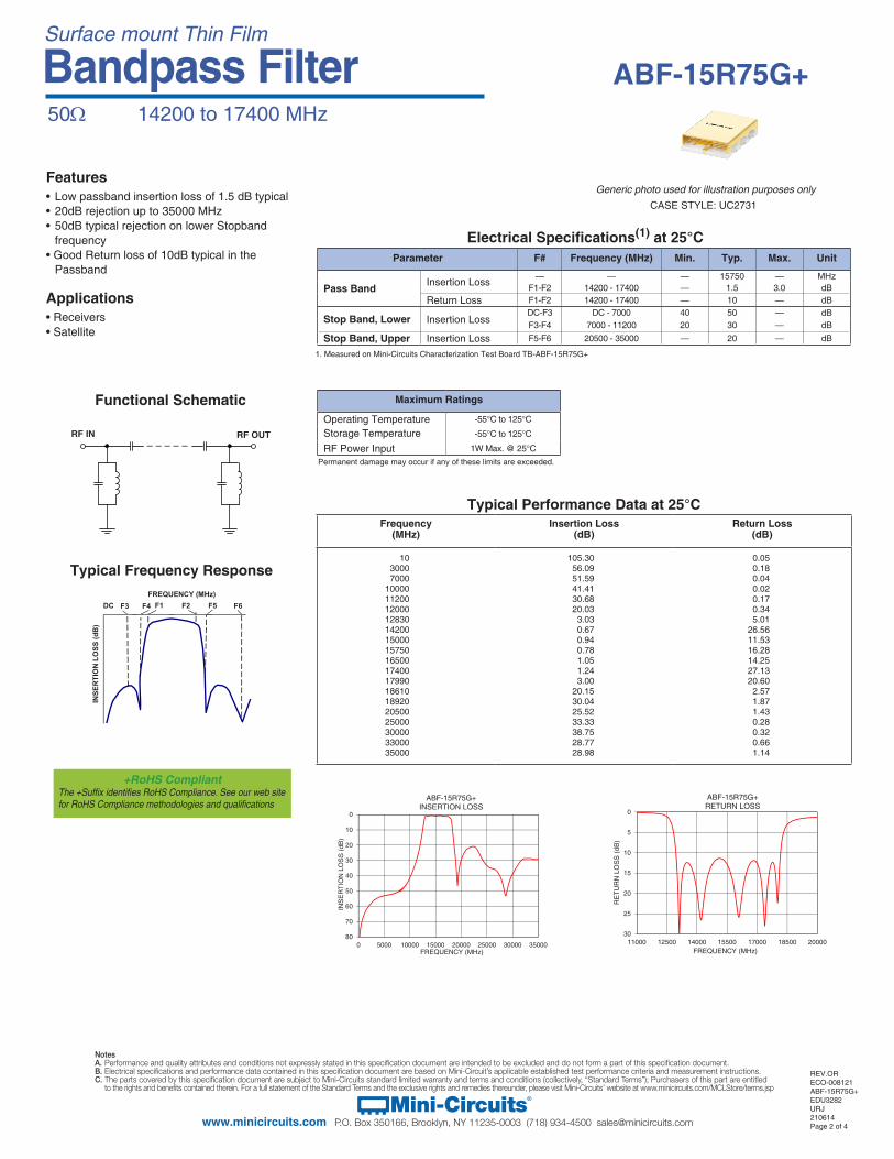
Electrical Specifications(1) at 25°C
Maximum Ratings
Operating Temperature -55°C to 125°C
Storage Temperature -55°C to 125°C
RF Power Input 1W Max. @ 25°C
REV.ORECO-008121ABF-15R75G+EDU3282URJ210614Page 2 of 4
Typical Frequency Response
Functional Schematic
Typical Performance Data at 25°C
50Ω 14200 to 17400 MHz
Bandpass Filter
Applications• Receivers• Satellite
Features• Low passband insertion loss of 1.5 dB typical• 20dB rejection up to 35000 MHz• 50dB typical rejection on lower Stopband frequency• Good Return loss of 10dB typical in the Passband
RF IN RF OUT
Parameter F# Frequency (MHz) Min. Typ. Max. Unit
Pass Band Insertion Loss — — — 15750 — MHzF1-F2 14200 - 17400 — 1.5 3.0 dB
Return Loss F1-F2 14200 - 17400 — 10 — dB
Stop Band, Lower Insertion LossDC-F3 DC - 7000 40 50 — dBF3-F4 7000 - 11200 20 30 — dB
Stop Band, Upper Insertion Loss F5-F6 20500 - 35000 — 20 — dB
F1 F2FREQUENCY (MHz)
INSE
RTI
ON
LO
SS (d
B)
F5F4 F6DC F3
+RoHS CompliantThe +Suffix identifies RoHS Compliance. See our web site for RoHS Compliance methodologies and qualifications
Permanent damage may occur if any of these limits are exceeded.
1. Measured on Mini-Circuits Characterization Test Board TB-ABF-15R75G+
0
5
10
15
20
25
3011000 12500 14000 15500 17000 18500 20000
RE
TUR
N L
OS
S (d
B)
FREQUENCY (MHz)
ABF-15R75G+RETURN LOSS
0
10
20
30
40
50
60
70
800 5000 10000 15000 20000 25000 30000 35000
INS
ER
TIO
N L
OS
S (d
B)
FREQUENCY (MHz)
ABF-15R75G+INSERTION LOSS
Frequency (MHz)
Insertion Loss(dB)
Return Loss(dB)
10 105.30 0.05 3000 56.09 0.18 7000 51.59 0.04 10000 41.41 0.02 11200 30.68 0.17 12000 20.03 0.34 12830 3.03 5.01 14200 0.67 26.56 15000 0.94 11.53 15750 0.78 16.28 16500 1.05 14.25 17400 1.24 27.13 17990 3.00 20.60 18610 20.15 2.57 18920 30.04 1.87 20500 25.52 1.43 25000 33.33 0.28 30000 38.75 0.32 33000 28.77 0.66 35000 28.98 1.14
CASE STYLE: UC2731
Generic photo used for illustration purposes only
Bandpass Filter
NotesA. Performance and quality attributes and conditions not expressly stated in this specification document are intended to be excluded and do not form a part of this specification document. B. Electrical specifications and performance data contained in this specification document are based on Mini-Circuit’s applicable established test performance criteria and measurement instructions. C. The parts covered by this specification document are subject to Mini-Circuits standard limited warranty and terms and conditions (collectively, “Standard Terms”); Purchasers of this part are entitled to the rights and benefits contained therein. For a full statement of the Standard Terms and the exclusive rights and remedies thereunder, please visit Mini-Circuits’ website at www.minicircuits.com/MCLStore/terms.jsp
Mini-Circuits®
www.minicircuits.com P.O. Box 350166, Brooklyn, NY 11235-0003 (718) 934-4500 [email protected]
ABF-15R75G+
Page 3 of 4
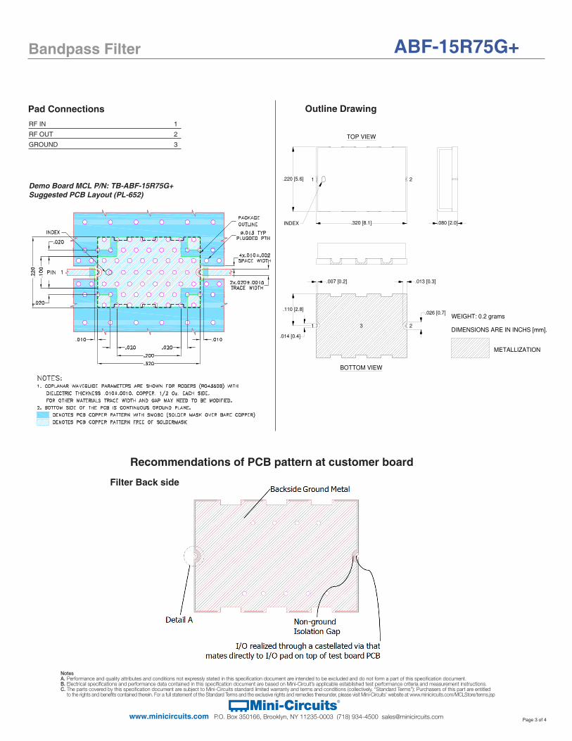
Outline Drawing
Demo Board MCL P/N: TB-ABF-15R75G+Suggested PCB Layout (PL-652)
.013 [0.3]
BOTTOM VIEW
TOP VIEW
INDEX
METALLIZATION
.026 [0.7]
DIMENSIONS ARE IN INCHS [mm].
WEIGHT: 0.2 grams
.320 [8.1]
.220 [5.6]
.080 [2.0]
21
21 3
.110 [2.8]
.007 [0.2]
.014 [0.4]
RF IN 1
RF OUT 2
GROUND 3
Recommendations of PCB pattern at customer board
Filter Back side
Pad Connections

Bandpass Filter
NotesA. Performance and quality attributes and conditions not expressly stated in this specification document are intended to be excluded and do not form a part of this specification document. B. Electrical specifications and performance data contained in this specification document are based on Mini-Circuit’s applicable established test performance criteria and measurement instructions. C. The parts covered by this specification document are subject to Mini-Circuits standard limited warranty and terms and conditions (collectively, “Standard Terms”); Purchasers of this part are entitled to the rights and benefits contained therein. For a full statement of the Standard Terms and the exclusive rights and remedies thereunder, please visit Mini-Circuits’ website at www.minicircuits.com/MCLStore/terms.jsp
Mini-Circuits®
www.minicircuits.com P.O. Box 350166, Brooklyn, NY 11235-0003 (718) 934-4500 [email protected] Page 4 of 4
1) Customer PCB’s ground pattern length (dimension A) can be similar to filter length.2) Customer PCB’s ground pattern width (dimension B) can be similar filter width.3) Dimensions C and D on Filter RF I/O detail and Customer PCB pattern can be closely match. The dimensions of C and D on the Customer PCB pattern can be slightly larger to account for component alignment tolerance (ground metal can be pulled back from RF I/O trace).4) Recommend to use Solder mask at Customer PCB at outer area of filter pattern/ footprint without any clearance.5) Recommended to use Solder mask at I/O of Customer PCB with 5mil clearance from filter I/O edge (dimension E).
Comments on component handling and solder attach
1) Avoid using soldering iron directly to the ceramic filter. This would lead to development of crack in the component due to thermal shock.2) Vacuum pick-up tool or plastic tweezers are recommended for handling the components. Extra care should be taken not to scratch the filter or metal area.3) Use 2-3 mil thickness stencil plate and screen print the solder. Refer below picture for recommended stencil pattern to get the best solder attachment.
4) Plugged ground vias in the PWB will improve attachment consistency.5) Recommended to have a similar or closer test board material and thickness (refer Mini-Circuits evaluation board for details) to minimize the CTE over the temperature range.
Stencil opening drawing Solder location after screen print

![[H.a. Macleod] Thin-Film Optical Filters](https://static.fdocuments.in/doc/165x107/553ff9e8550346096e8b4989/ha-macleod-thin-film-optical-filters.jpg)