Surface modification of armos fibers with oxygen plasma treatment for improving interfacial adhesion...
8
Surface Modification of Armos Fibers with Oxygen Plasma Treatment for Improving Interfacial Adhesion with Poly(phthalazinone ether sulfone ketone) Resin Jing Wang, 1 Ping Chen, 1,2 Wei Liu, 3 Hong Li, 1 Caixia Jia, 1 Chun Lu, 2 Baichen Wang 2 1 State Key Laboratory of Material Surface Modification by Laser, Ion and Electronic Beams, School of Chemical Engineering, Dalian University of Technology, Dalian 116012, China 2 Center for Composite Materials, Shenyang Institute of Aeronautical Engineering, Shenyang 110034, China 3 Dalian Education University, Dalian 116021, China Received 24 August 2009; accepted 23 November 2010 DOI 10.1002/app.33847 Published online 29 March 2011 in Wiley Online Library (wileyonlinelibrary.com). ABSTRACT: We introduce in this article oxygen plasma treatment as a convenient and effective method for the surface modification of Armos fibers. The effects of oxy- gen-plasma-treatment power on both the Armos fiber surface properties and Armos-fiber-reinforced poly(phtha- lazinone ether sulfone ketone) composite interfacial adhe- sion were investigated. The Armos fiber surface chemical composition, surface morphology and roughness, and sur- face wettability as a function of oxygen-plasma-treatment power were measured by X-ray photoelectron spectros- copy, scanning electronic microscopy, atomic force micros- copy, and dynamic contact angle analysis. The results show that oxygen plasma treatment introduced a lot of reactive functional groups onto the fiber surface, changed the surface morphology, increased the surface roughness, and enhanced the surface wettability. Additionally, the effect of the oxygen-plasma-treatment power on the com- posite interfacial adhesion was measured by interlaminar shear strength with a short-beam bending test. Oxygen plasma treatment was an effective method for improving the composite interfacial properties by both chemical bonding and physical effects. V C 2011 Wiley Periodicals, Inc. J Appl Polym Sci 121: 2804–2811, 2011 Key words: adhesion; composites; fibers; interfaces; surface INTRODUCTION Advanced polymer–matrix composites made from aramid fibers have been widely used in many appli- cations, such as aircraft, automobiles, sporting goods, and medical devices, because the fibers com- bine a high specific modulus and strength. 1 To exert the excellent mechanical properties of Aramid fibers in composite systems, the optimization of the inter- facial adhesion properties between the fiber and the matrix seems to be more necessary. It is well known that the interfacial region plays a major role in the overall mechanical performance of composite materi- als for transferring stress from the matrix to the fiber under load-bearing conditions. Recently, a few researchers have focused on the analysis of the com- posite interfacial properties. 2,3 Poly(phthalazinone ether sulfone ketone) (PPESK) is one kind of novel thermoplastic resin with excel- lent mechanical properties, high damage tolerance, and remarkable thermal and chemical resistance. Compared with traditional thermoplastic resins, it is provided with the higher heat-resistant grade and better solubility; it can be dissolved in some usual solvents. Thus, fiber-reinforced PPESK composites can be prepared through a solution impregnation technique. 2 However, the Aramid fiber has poor adhesion with the matrix in the composite system because of its inert chemical structure and smooth surface; this limits the exertion of the composite properties. At this point, several methods have been developed to modify the fiber surface, such as chemical treatment (including coupling agent and chemical grafting methods), surface coating methods, and plasma treatment. 4–10 Low-temperature plasma treatment has been shown to be an effective method for modifying or- ganic fiber surfaces. 11,12 This method offers several advantages, including the selection modification of only the outer atomic layers of the substrate, the Correspondence to: P. Chen ([email protected]). Contract grant sponsor: National Natural Science Foundation of China; contract grant number: 50743012. Contract grant sponsor: National Defense 11th 5-Year Program of the Foundational Research Program; contract grant number: A3520060215. Contract grant sponsor: Innovative Research Team Program in University of Liaoning Education Department; contract grant number: LT2010083. Journal of Applied Polymer Science, Vol. 121, 2804–2811 (2011) V C 2011 Wiley Periodicals, Inc.
Transcript of Surface modification of armos fibers with oxygen plasma treatment for improving interfacial adhesion...

Surface Modification of Armos Fibers with Oxygen PlasmaTreatment for Improving Interfacial Adhesion withPoly(phthalazinone ether sulfone ketone) Resin
Jing Wang,1 Ping Chen,1,2 Wei Liu,3 Hong Li,1 Caixia Jia,1 Chun Lu,2 Baichen Wang2
1State Key Laboratory of Material Surface Modification by Laser, Ion and Electronic Beams, School of ChemicalEngineering, Dalian University of Technology, Dalian 116012, China2Center for Composite Materials, Shenyang Institute of Aeronautical Engineering, Shenyang 110034, China3Dalian Education University, Dalian 116021, China
Received 24 August 2009; accepted 23 November 2010DOI 10.1002/app.33847Published online 29 March 2011 in Wiley Online Library (wileyonlinelibrary.com).
ABSTRACT: We introduce in this article oxygen plasmatreatment as a convenient and effective method for thesurface modification of Armos fibers. The effects of oxy-gen-plasma-treatment power on both the Armos fibersurface properties and Armos-fiber-reinforced poly(phtha-lazinone ether sulfone ketone) composite interfacial adhe-sion were investigated. The Armos fiber surface chemicalcomposition, surface morphology and roughness, and sur-face wettability as a function of oxygen-plasma-treatmentpower were measured by X-ray photoelectron spectros-copy, scanning electronic microscopy, atomic force micros-copy, and dynamic contact angle analysis. The resultsshow that oxygen plasma treatment introduced a lot of
reactive functional groups onto the fiber surface, changedthe surface morphology, increased the surface roughness,and enhanced the surface wettability. Additionally, theeffect of the oxygen-plasma-treatment power on the com-posite interfacial adhesion was measured by interlaminarshear strength with a short-beam bending test. Oxygenplasma treatment was an effective method for improvingthe composite interfacial properties by both chemicalbonding and physical effects. VC 2011 Wiley Periodicals, Inc.J Appl Polym Sci 121: 2804–2811, 2011
Key words: adhesion; composites; fibers; interfaces;surface
INTRODUCTION
Advanced polymer–matrix composites made fromaramid fibers have been widely used in many appli-cations, such as aircraft, automobiles, sportinggoods, and medical devices, because the fibers com-bine a high specific modulus and strength.1 To exertthe excellent mechanical properties of Aramid fibersin composite systems, the optimization of the inter-facial adhesion properties between the fiber and thematrix seems to be more necessary. It is well knownthat the interfacial region plays a major role in theoverall mechanical performance of composite materi-als for transferring stress from the matrix to the fiberunder load-bearing conditions. Recently, a few
researchers have focused on the analysis of the com-posite interfacial properties.2,3
Poly(phthalazinone ether sulfone ketone) (PPESK)is one kind of novel thermoplastic resin with excel-lent mechanical properties, high damage tolerance,and remarkable thermal and chemical resistance.Compared with traditional thermoplastic resins, it isprovided with the higher heat-resistant grade andbetter solubility; it can be dissolved in some usualsolvents. Thus, fiber-reinforced PPESK compositescan be prepared through a solution impregnationtechnique.2
However, the Aramid fiber has poor adhesionwith the matrix in the composite system because ofits inert chemical structure and smooth surface; thislimits the exertion of the composite properties. Atthis point, several methods have been developed tomodify the fiber surface, such as chemical treatment(including coupling agent and chemical graftingmethods), surface coating methods, and plasmatreatment.4–10
Low-temperature plasma treatment has beenshown to be an effective method for modifying or-ganic fiber surfaces.11,12 This method offers severaladvantages, including the selection modification ofonly the outer atomic layers of the substrate, the
Correspondence to: P. Chen ([email protected]).Contract grant sponsor: National Natural Science
Foundation of China; contract grant number: 50743012.Contract grant sponsor: National Defense 11th 5-Year
Program of the Foundational Research Program; contractgrant number: A3520060215.
Contract grant sponsor: Innovative Research TeamProgram in University of Liaoning Education Department;contract grant number: LT2010083.
Journal of Applied Polymer Science, Vol. 121, 2804–2811 (2011)VC 2011 Wiley Periodicals, Inc.

selection of the desired functional groups, the mini-mization of thermal degradation, and a rapid treat-ment time.13 In recent years, plasma treatments havebeen more popular than other methods of surfacetreatment because increasing concern about environ-mental pollution problems has limited chemical sur-face treatments.14
The objective of this study was to investigate theeffects of oxygen-plasma-treatment power on boththe Armos fiber surface and Armos-fiber-reinforcedPPESK composite interfacial adhesion. The surfacechemical composition, surface morphology androughness, and surface wettability before and afteroxygen plasma treatment under different powerswere measured by X-ray photoelectron spectroscopy(XPS), scanning electronic microscopy (SEM), atomicforce microscopy (AFM), and dynamic contact angleanalysis (DCAA), respectively. The influence of oxy-gen plasma treatment on the composite interfacialadhesion was measured by interlaminar shearstrength (ILSS) with a short-beam bending test.
EXPERIMENTAL
Materials
Armos fibers, one kind of high-performance aramidfibers supplied by Tverchimovolokno, J.-S., Russia,were used as the reinforcement in our experiment.They were cleaned successively with acetone anddistilled water and then dried in a vacuum oven.The matrix was PPESK supplied by Dalian PolymerNew Material Co., Ltd. (Dalian, China). The charac-teristic viscosity was 0.53, the glass-transition tem-perature was 284�C, and the molecular structurewas reported previously.2
Plasma treatment
The plasma was excited by an inductive-coupling,radio-frequency generator (13.56 MHz). The systemcontained a mass flow controller for an oxygen gasinlet, a pressure gauge, a vacuum pump, and a radiosource. Oxygen was fed into the vacuum chamber ata flow rate of about 30–40 cm3/min. The operationpressure was set at 30 Pa. Fibers were rolled on aglass frame and fixed in a quartz obturator 30 cm inheight and 26 cm in inner diameter. After oxygenplasma treatment of the fibers for 10 min under dif-ferent power levels from 120 to 240 W, the fiberswere immediately transferred to a dry box to mini-mize potential contamination.
Composite specimen preparation
Armos-fiber-reinforced PPESK composites were pre-pared through a solution impregnating technique
according to Chen et al.15 PPESK resin was dis-solved in N,N-dimethylacetamide (DMAc) solvent(15 wt %), and then, both the untreated and plasma-treated fibers were soaked with the PPESK/DMAcsolution. Monolayer impregnating samples wereused to vaporize the DMAc solvent (120�C/1 h,175�C/3 h, oven) and then made by a compression-molding technique. The volume fraction of Armosfibers in the composite was controlled at about 55%.
Morphology observation by SEM and AFM
The single-fiber surface morphologies were observedby SEM (QUANTA 200, FEI, Netherlands). Thechamber pressure was evacuated to a pressure lowerthan 60 Pa through a molecule pump. The magnifi-cation of the image for single fibers was set at5000�. In addition, the fiber surface morphologieson a microscopic scale (4 � 4 lm2) were observedby AFM (Picoplus II, America) in tapping (noncon-tact) mode, and the surface roughnesses, includingthe root mean square roughness (Rq) and arithmeticmean roughness (Ra), were calculated from eqs. (1)and (2) by the instrument software:
Rq ¼
ffiffiffiffiffiffiffiffiffiffiffiffiffiffiffiffiffiffiffiffiffiffiffiffiffiffiffiffiffiffiffiffiffiffiffiffiffiffiffiffiffiffiffiffi1
N2
XN
i¼1
XN
j¼1
ðzij � zavÞ2vuut (1)
Ra ¼1
N
XN
i¼1
XN
j¼1
zij � zcp
�� �� (2)
where N is the number of data points in the image, iand j are pixel locations on the AFM image, zij is theheight value at i and j locations, zav is the averageheight value within the given area, and zcp is theheight value from the center plane.16
Chemical composition analysis by XPS
The fiber surface chemical composition of the Armosfibers were determined by XPS (ESCALAB 250,Thermo, America), with the use of a monochromaticAl Ka (hm ¼ 1486.6 eV) X-ray radiation source (volt-age ¼ 15 kV, wattage ¼ 250 W) from a dual Al–Mganode. The vacuum chamber was pumped to lowerthan 3.0 � 10�9 Torr. Spectra were acquired at atakeoff angle of 90� relative to the sample surface.An electron kinetic energy analyzer plotted the in-tensity of the emitted photoelectrons according totheir binding energies. The analyzer was operated inconstant-energy mode with a pass energy of 50 eVfor elemental quantification purposes. The surfacechemical composition was calculated from the areasof relevant spectral peaks. The sampling depth wasless than 5 nm.
SURFACE MODIFICATION OF ARMOS FIBERS 2805
Journal of Applied Polymer Science DOI 10.1002/app
Wettability measured by DCAA
The dynamic contact angle was measured by a CahnDCA-322 (Thermo, America) analysis system accord-ing to the Wilhelmy technique.17 The fiber samplewas cut to about 1 cm in length, fixed indirectly to a
wire suspended from a microbalance, and thenimmersed in the testing liquid medium by anincrease in the elevating stage at a constant speed of1 mm/min. The contact angles were calculated witha computer system with eq. (3). The surface free
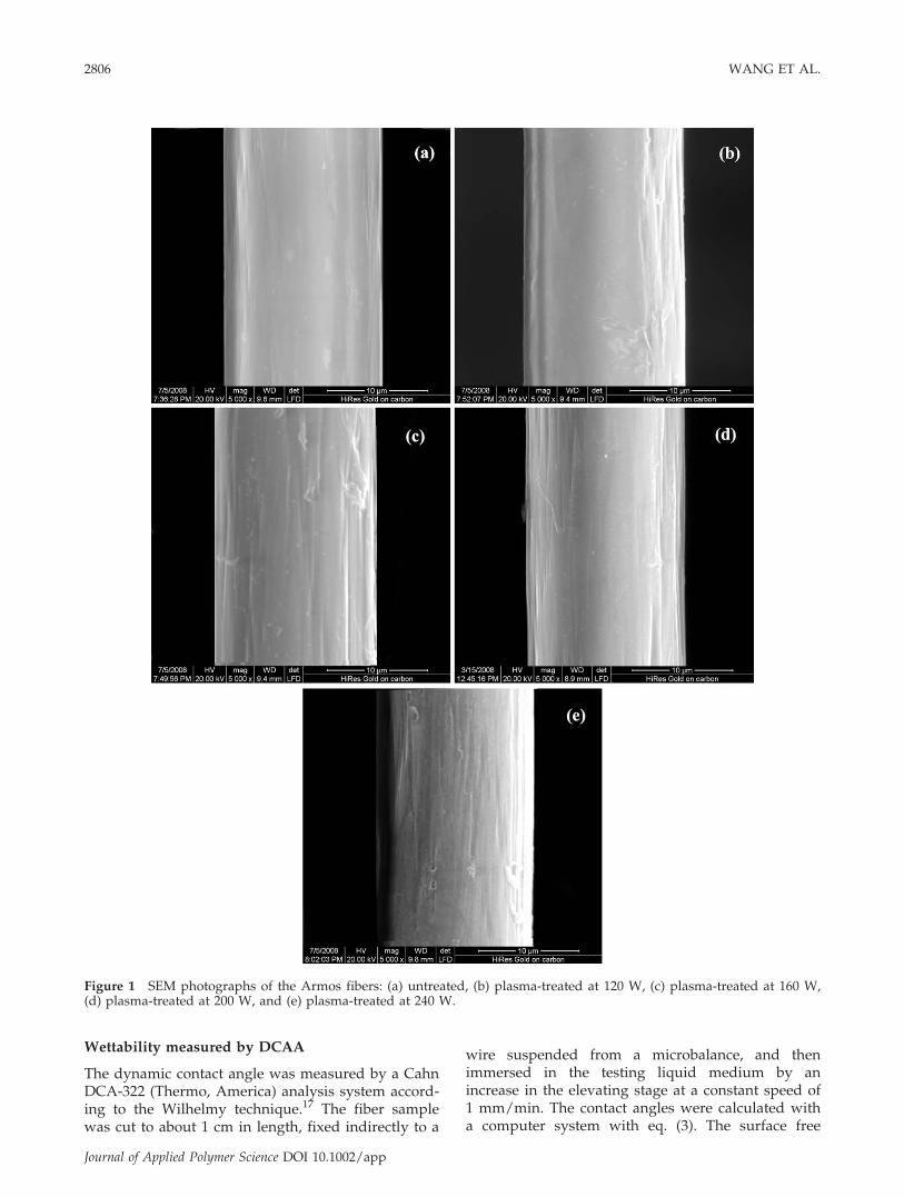
Figure 1 SEM photographs of the Armos fibers: (a) untreated, (b) plasma-treated at 120 W, (c) plasma-treated at 160 W,(d) plasma-treated at 200 W, and (e) plasma-treated at 240 W.
2806 WANG ET AL.
Journal of Applied Polymer Science DOI 10.1002/app

energy was calculated from the Owens–Wendt equa-tions [eqs. (4) and (5)]:
F ¼ cp cos h: (3)
clð1þ cos hÞ ¼ 2ffiffiffiffiffiffiffiffifficp
s cpl
qþ 2
ffiffiffiffiffiffiffiffifficd
s cdl
q(4)
cTotal ¼ cps þ cd
s (5)
where F is the wetting force measured by the micro-balance, c is surface free energy, p is the wetted pe-rimeter, y is the contact angle between the fiber andthe liquid, cl is the surface tension of the testing liq-uid, cTotal is the surface free energy of the fiber, andcp
s is the polar component and cds is the dispersive
Figure 2 AFM photographs of the Armos fibers: (a) untreated, (b) plasma-treated at 120 W, (c) plasma-treated at 160 W,(d) plasma-treated at 200 W, and (e) plasma-treated at 240 W. [Color figure can be viewed in the online issue, which isavailable at wileyonlinelibrary.com.]
SURFACE MODIFICATION OF ARMOS FIBERS 2807
Journal of Applied Polymer Science DOI 10.1002/app

component of the surface free energy of the fiber.
ILSS measurement
ILSS was measured on a Shimadzu, Japan universaltesting machine with a three-point short-beam bend-ing test method according to GB3357-82. The speci-men dimensions were 25 � 6 � 2 mm3, with a span-to-thickness ratio of 5. The specimens were tested ata constant crosshead movement rate of 2 mm/min.ILSS was calculated according to the followingexpression:
C ¼ 3Pb
4bh(6)
where C is the interlaminar shear strength (MPa), Pb
is the maximum compression load at fracture (N), bis the width of the specimen (mm), and h is thethickness of the specimen (mm). Each ILSS valuereported was the average of five tested specimens.
RESULTS AND DISCUSSION
Influence of the oxygen-plasma-treatment poweron the Armos fiber surface morphology andsurface roughness
Figure 1 shows the single-fiber surface morphologiesobserved by SEM. Compared with the untreatedfiber sample in Figure 1(a), the surfaces were rough-ened after oxygen plasma treatment, as shown inFigure 1(b–e). Furthermore, AFM was used to detectthe surface changes on a microscopic scale. Thethree-dimensional morphological images of theuntreated and oxygen-plasma-treated samples underdifferent powers are shown in Figure 2. The resultsseemed to consistent with the SEM photographs.The fiber surface was clean and smooth for theuntreated sample shown in Figure 2(a) and left somestreaks caused by the intrinsic structure of theArmos fiber.18 After plasma treatment at 120 W,some small protrusions were evident, as shown inFigure 2(b); with increasing plasma-treatment power,more and more granules emerged and were well-distributed on the surface, as shown in Figure 2(c,d).
The results indicate that oxygen plasma treatmentroughened the fiber surface and led to increases inthe contact area with the matrix and the frictionbetween the fiber and the matrix to improve thecomposite interfacial adhesion. However, as theplasma-treatment power reached 240 W, some biggrooves were observed on the surface, as shown inFigure 2(e). This may have been the result of etchingeffects by the oxygen plasma treatment with pro-longed power.
The surface roughnesses, including Rq and Ra,were changed after oxygen plasma treatment, andthe results are shown in Table I. Rq increased from197 nm for the untreated sample to 279 nm for theplasma-treated sample with a power of 200 W. How-ever, with the plasma-treatment power increasing to240 W, the surface roughness began to decrease; thismay have been due to surface ablation under thehigh plasma-treatment power because the higherplasma-treatment power brought more reactive par-ticles with higher energies and thermal effects onthe fiber surface.19 From the results of SEM andAFM, we found that the oxygen plasma treatmentchanged the fiber surface morphology and enhancedthe surface roughness under the proper power.
Influence of the oxygen-plasma-treatment poweron the Armos fiber surface chemical composition
XPS was used to analyze the chemical compositionof the Armos fiber surface. Because the samplingdepth was less than 5 nm, the surface compositioncould be very different from the bulk composition.Through calculation of the peak areas of carbon,oxygen, and nitrogen, we obtained the relative
TABLE ISurface Roughnesses (Rq and Ra) of the Armos Fibers
Under Different Plasma-Treatment Powers
Sample Rq (nm) Ra (nm)
Untreated 197 180Plasma-treated at 120 W 229 218Plasma-treated at 160 W 226 216Plasma-treated at 200 W 279 261Plasma-treated at 240 W 195 177
TABLE IISurface Chemical Compositions of the Armos Fibers Under Different Plasma-Treatment Powers
Sample
Chemical composition (at %) Atomic ratio
C1s O1s N1s O1s/C1s N1s/C1s
Untreated 81.9 11.1 7.0 0.14 0.09Plasma-treated at 120 W 69.1 23.3 7.6 0.34 0.11Plasma-treated at 160 W 71.6 17.4 11.0 0.24 0.15Plasma-treated at 200 W 73.7 15.2 11.1 0.21 0.15Plasma-treated at 240 W 71.3 16.3 12.4 0.23 0.17
2808 WANG ET AL.
Journal of Applied Polymer Science DOI 10.1002/app

TABLE IIIContents of the Functional Groups of the Armos Fibers Under Different Plasma-Treatment Powers
Sample
Contents of the functional groups (%)
ACACA (284.5 eV) ACANA (285.5 eV) ACAOA (286.5 eV) AC¼¼O (287.7 eV) ACOOA (289.2 eV)
Untreated 71.9 12.3 6.7 6.0 3.1Plasma-treated at 120 W 71.9 11.5 5.0 5.8 5.8Plasma-treated at 160 W 62.5 16.2 6.9 8.8 5.6Plasma-treated at 200 W 61.9 13.4 6.6 10.9 7.2Plasma-treated at 240 W 65.4 8.5 11.1 8.5 6.5
Figure 3 C1s spectra of the Armos fibers: (a) untreated, (b) plasma-treated at 120 W, (c) plasma-treated at 160 W,(d) plasma-treated at 200 W, and (e) plasma-treated at 240 W.
SURFACE MODIFICATION OF ARMOS FIBERS 2809
Journal of Applied Polymer Science DOI 10.1002/app
chemical compositions; these are listed in Table II.The surface carbon and oxygen concentrations were81.9 and 11.1%, and the O/C ratio was 0.14 for theuntreated sample. With a plasma-treatment powerof 120 W, the surface carbon concentration decreasedsharply to 69.1%, the surface oxygen concentrationincreased obviously to 23.3%, and the O/C ratioincreased to 0.34. An explanation is that the oxygenplasma treatment introduced oxygen-containingfunctional groups onto the fiber surface at lowerplasma-treatment powers. Nitrogen seemed to expe-rience a small change before and after plasma treat-ment under different powers.
Figure 3 shows the C1s spectra of the Armosfibers before and after oxygen plasma treatmentunder different powers. According to the calculationof each peak area, we obtained the relative contentof functional groups, as shown in Table III. Obviouschanges in AC¼¼O and ACOOA concentrations weredetected after oxygen plasma-treatment at more than160 W; this improved the surface chemical reactivityand then enhanced the chemical bonding betweenthe fiber and the matrix in the composite system.20
However, with the plasma-treatment power increasingto 240 W, these two functional group concentrationsdecreased. We suggest that there existed an optimumplasma-treatment power.
Influence of the oxygen-plasma-treatment poweron the Armos fiber surface wettability
The effect of the oxygen-plasma-treatment power onthe fiber surface wettability was revealed bydynamic contact angle measurement. From the datain Table IV, we observed that the oxygen plasmatreatment was quite effective in modifying the fibersurface. The contact angle with water decreasedsharply after plasma treatment, whereas the diiodo-methane contact angle increased. Moreover, the po-lar component for the plasma-treated sample washigher than that of the untreated one. This phenom-enon may have been due to many active functionalgroups introduced onto the fiber surface by plasma,as shown in XPS analysis. The high polar componentof the total surface free energy was expected to con-tribute to good wettability and adhesion betweenthe fiber and the matrix.14
Influence of the oxygen-plasma-treatment poweron the Armos-fiber-reinforced PPESK compositeinterfacial adhesion
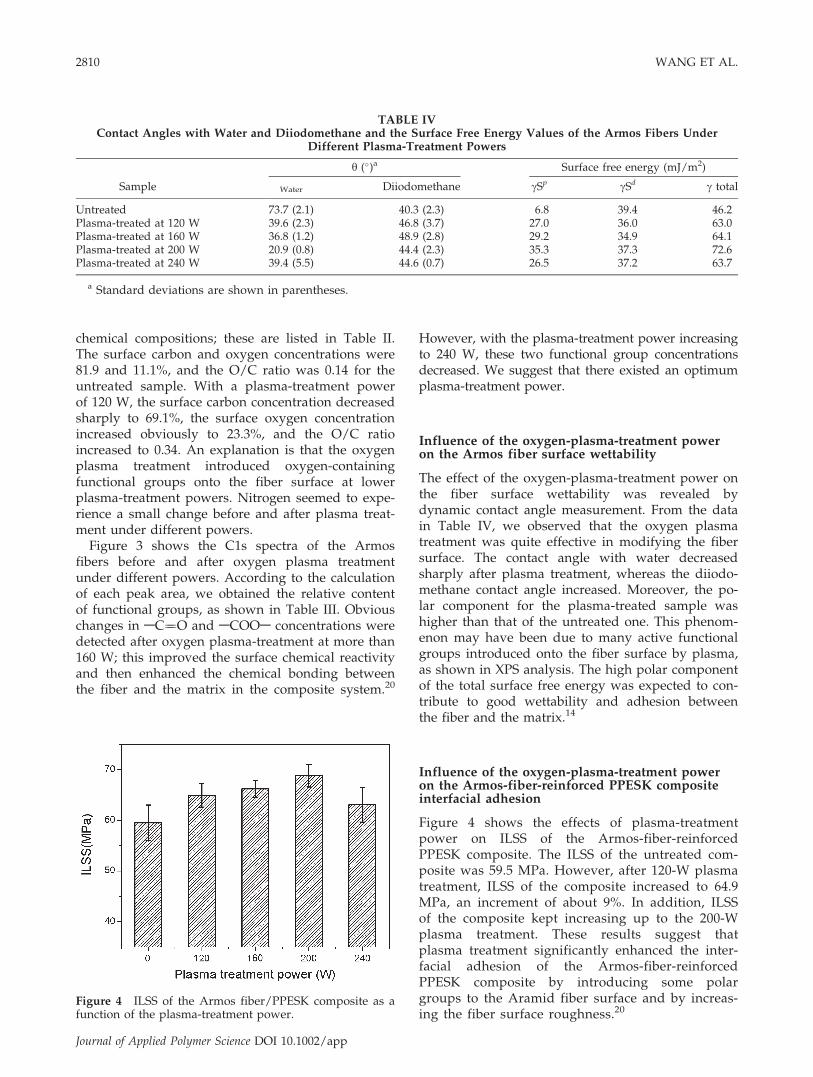
Figure 4 shows the effects of plasma-treatmentpower on ILSS of the Armos-fiber-reinforcedPPESK composite. The ILSS of the untreated com-posite was 59.5 MPa. However, after 120-W plasmatreatment, ILSS of the composite increased to 64.9MPa, an increment of about 9%. In addition, ILSSof the composite kept increasing up to the 200-Wplasma treatment. These results suggest thatplasma treatment significantly enhanced the inter-facial adhesion of the Armos-fiber-reinforcedPPESK composite by introducing some polargroups to the Aramid fiber surface and by increas-ing the fiber surface roughness.20
TABLE IVContact Angles with Water and Diiodomethane and the Surface Free Energy Values of the Armos Fibers Under
Different Plasma-Treatment Powers
Sample
y (�)a Surface free energy (mJ/m2)
Water Diiodomethane cSp cSd c total
Untreated 73.7 (2.1) 40.3 (2.3) 6.8 39.4 46.2Plasma-treated at 120 W 39.6 (2.3) 46.8 (3.7) 27.0 36.0 63.0Plasma-treated at 160 W 36.8 (1.2) 48.9 (2.8) 29.2 34.9 64.1Plasma-treated at 200 W 20.9 (0.8) 44.4 (2.3) 35.3 37.3 72.6Plasma-treated at 240 W 39.4 (5.5) 44.6 (0.7) 26.5 37.2 63.7
a Standard deviations are shown in parentheses.
Figure 4 ILSS of the Armos fiber/PPESK composite as afunction of the plasma-treatment power.
2810 WANG ET AL.
Journal of Applied Polymer Science DOI 10.1002/app

CONCLUSIONS
Oxygen plasma treatment was applied to modify theArmos fiber surface for improving the interfacial ad-hesion between the high-performance fiber and akind of advanced thermoplastic matrix, PPESK. Dif-ferent plasma-treatment powers on the fiber surfaceand the composite interfacial properties were inves-tigated. The SEM and AFM results show that thefiber surface morphology was roughened and thatthe surface roughness increased after oxygen plasmatreatments with powers lower than 200 W. XPS anal-ysis indicated that surface carbon concentrationdecreased and the oxygen concentration increasedafter oxygen plasma treatment. The introduced oxy-gen element reacted with the fiber surface atomsand then formed oxygen-containing functionalgroups, such as AC¼¼O and ACOOA, whichimproved the fiber surface wettability and enhancedthe composite interfacial adhesion. DCAA resultsproved that surface wettability improved largely af-ter oxygen plasma treatment. The contact angleswith water decreased obviously and the surface freeenergy increased accordingly. The ILSS values of theplasma-treated fiber samples under various plasma-treatment powers were enhanced. However, greaterpowers, as high as 240 W, did not improve ILSS fur-ther. Therefore, we concluded that there existed anoptimum plasma treatment condition.
References
1. Coffey, A. B.; Bradaigh, C. M. O.; Young, R. J. J Mater Sci2007, 42, 8053.
2. Chen, P.; Wang, J.; Wang, B. C.; Li, W.; Zhang, C. S.; Li, H.;Sun, B. L. Surf Interface Anal 2009, 41, 38.
3. Seo, M. K.; Park, S. J. J Colloid Interface Sci 2009, 330, 237.4. Wu, J.; Cheng, X. H. J Appl Polym Sci 2006, 102, 4165.5. Wu, S. R.; Sheu, G. S.; Shyu, S. S. J Appl Polym Sci 1996, 62, 1347.6. De Lange, P. J.; Akker, P. G.; Mader, E. Compos Sci Technol
2007, 67, 2027.7. Day, R. J.; Hewson, K. D.; Lovell, P. A. Compos Sci Technol
2002, 62, 153.8. Maity, J.; Jacob, C.; Das, C. K. J Appl Polym Sci 2008, 107,
3739.9. Liu, L.; Jiang, Q.; Zhu, T. J Appl Polym Sci 2006, 102, 242.
10. Yip, J.; Chan, K.; Sin, K. M. Polym Int 2004, 53, 634.11. Brown, J. R.; Mathys, Z. J Mater Sci 1997, 32, 2599.12. Wang, J.; Chen, P.; Li, H.; Li, W.; Wang, B. C.; Zhang, C. S.;
Ren, N. Surf Interface Anal 2008, 40, 1299.13. Yip, J.; Chan, K.; Sin, K. M. Appl Surf Sci 2006, 253, 2493.14. Park, J. M.; Kim, D. S.; Kim, S. R. J Colloid Interface Sci 2003,
264, 431.15. Chen, P.; Zhang, C. S.; Wang, J. Chin. Pat. 2006, ZL200610134662.3.16. Zukiene, K.; Jankauskaite, V.; Petraitiene S. Appl Surf Sci
2006, 253, 966.17. Lu, C.; Chen, P.; Yu, Q.; Ding, Z. F.; Lin, Z. W.; Li, W. J Appl
Polym Sci 2007, 106, 1733.18. Zhang, Y. H.; Huang, Y. D.; Liu, L.; Wu, L. N. J Appl Polym
Sci 2007, 106, 2251.19. Chen, P.; Zhang, C. S.; Zhang, X. Y.; Wang, B. C.; Li, W.; Lei,
Q. Q. Appl Surf Sci 2008, 255, 3153.20. Wang, J.; Chen, P.; Li, H.; Zhang, C. S.; Sun, B. L.; Zhang, X.
Y. Surf Coat Technol 2008, 202, 4986.
SURFACE MODIFICATION OF ARMOS FIBERS 2811
Journal of Applied Polymer Science DOI 10.1002/app


![Crystal structure of bis[bis(4-azaniumylphenyl) sulfone ......[bis(4,40-diazaniumylphenyl) sulfone] tetranitrate monohydrate}, the cations are conformationally similar, with comparable](https://static.fdocuments.in/doc/165x107/60b0786ebd8ffd67d34c0b4e/crystal-structure-of-bisbis4-azaniumylphenyl-sulfone-bis440-diazaniumylphenyl.jpg)


![MEMBRANES FOR FLUE GAS TREATMENT DISSERTATION · Poly styrene PS 970 388 [3, 6] Sulfonated poly ether sulfone ... Sulfonated poly ether ether ketone (S-PEEK) can be obtained by sulfonation](https://static.fdocuments.in/doc/165x107/6121e88d85512935481dfaa9/membranes-for-flue-gas-treatment-dissertation-poly-styrene-ps-970-388-3-6-sulfonated.jpg)