Surface Modification of AISI 1020 Mild Steel by Electrical ... · coating deposited on AISI 1020...
53
Surface Modification of AISI 1020 Mild Steel by Electrical Discharge Coating with Tungsten and Copper Mixed Powder Green Compact Electrodes Vipin Richhariya Department of Mechanical Engineering National Institute of Technology Rourkela Rourkela – 769 008, INDIA
Transcript of Surface Modification of AISI 1020 Mild Steel by Electrical ... · coating deposited on AISI 1020...
Surface Modification of AISI 1020 Mild Steel by Electrical
Discharge Coating with Tungsten and Copper Mixed
Powder Green Compact Electrodes
Vipin Richhariya
Department of Mechanical Engineering
National Institute of Technology Rourkela
Rourkela – 769 008, INDIA

Surface Modification of AISI 1020 Mild Steel by Electrical
Discharge Coating with Tungsten and Copper Mixed Powder
Green Compact Electrodes
THIS THESIS IS SUBMITTED
IN
THE PARTIAL FULLFILLMENT OF THE REQUIREMNT FOR THE DEGREE
OF
Master of Technology
in
Production Engineering
by
VIPIN RICHHARIYA
(Roll No.- 211ME2177)
Under the supervision of
Dr. MANOJ MASANTA
Department of Mechanical Engineering
National Institute of Technology Rourkela
Rourkela – 769 008, INDIA

Dedicated to my Family,
who always inspired me to do something beyond the reach
&
my Guru Raja Raghuraj Singh Ju Dev,
who not only taught me astrology, but also made me proficient in understanding the engineering of destiny
Page iii
Mechanical Engineering
National Institute of Technology Rourkela
Rourkela - 769 008, INDIA. www.nitrkl.ac.in
Dr. Manoj Masanta
Assistant Professor
Certificate
This is to certify that the thesis entitled “Surface Modification of AISI 1020 Mild Steel by
Electrical Discharge Coating with Tungsten and Copper Mixed Powder Green Compact
Electrodes” being submitted by Vipin Richhariya (211ME2177) for the partial fulfillment of the
requirements of Master of Technology degree in Production Engineering is a bonafide thesis
work done by him under my supervision during the academic year 2012-2013, in the Department of
Mechanical Engineering, National Institute of Technology Rourkela, India.
The results presented in this thesis have not been submitted elsewhere for the award of any other
degree or diploma.
Date: Dr. Manoj Masanta

Page iv
Acknowledgment
I would like to express my sincere gratitude to my guide Dr. Manoj Masanta, Mechanical
Engineering, NIT Rourkela, for giving us the opportunity to work with him and also
providing excellent guidance and continuous assistance throughout the project work. His
constant advice, assertions, appreciation were very vital and irrevocable, giving us that boost
without which it wouldn‟t have been possible for us to finish our project. I am thankful to
him for his encouragement throughout the project.
I also wish to express my deep sense of gratitude to Dr. K.P. Maity, HOD, Mechanical
Engineering, N.I.T. Rourkela for giving us an opportunity to work on this project and
valuable departmental facilities. I would be highly obliged to extend our thanks to Dr. B.C.
Ray, HOD, Metallurgy and Materials Science Engineering for his support and help rendered
by giving us the permissions to use their laboratory for carrying out our experiments, without
which the completion of this project would have been at stake . I would also like to thank all
the staff members of Mechanical Engineering Department., NITR. I would like to show my
gratitude to my very dear friends Mayank Agrawal, V Rakesh Kumar and Jyoti Singh Parihar
for their consistent support, immense help and continuous encouragement for the completion
of this project work.
Vipin Richhariya

Page v
Abstract
Electro discharge machining (EDM) is a non- conventional machining process, which is
widely used for machining of very hard materials used for engineering purposes. In Electrical
Discharge Coating (EDC) process tool electrode which is manufactured by powder
metallurgy (P/M) technique, connected to anode and work-piece (on which coating is to be
done) is selected as cathode in electro discharge machine (polarity opposite to the electrical
discharge machining). In presence of dielectric, tool electrode is worn out during EDM and
the material removed from the surface of electrode deposited over the work-piece surface.
This project work describes an advanced method of surface modification by Electrical
Discharge Coating (EDC). In this work Tungsten carbide and Copper (WC- Cu) composite
coating deposited on AISI 1020 mild steel substrate. Tungsten (W) and Copper (Cu) powder
in different weight percentages has been used for preparation of tool electrode by P/M
process. Effect of compact pressure, proportions of powder of materials (during tool
preparation) and peak current (during EDC) on deposition rate of the coating and tool wear
rate has been investigated.
By using X-Ray Diffraction (XRD) technique different phases formed in the deposited
layer during the process has been identified. Scanning Electron Microscopy (SEM) has been
done to reveal the microstructure of the coated surface. Vickers‟ Micro hardness testing has
been performed on the coating to measure the hardness values of coated surface.
Keywords: Electrical Discharge Coating (EDC); Electrical Discharge Machining (EDM);
Powder Metallurgy (P/M) Green Compact electrode; SEM; Vickers hardness; WC- Cu
composite coating; XRD
Page iii
Table of Contents
Certificate ............................................................................................................................................... iii
Acknowledgment ................................................................................................................................... iv
Abstract ................................................................................................................................................... v
Chapter 1 ................................................................................................................................................. 1
Introduction ......................................................................................................................................... 1
1.1 Various Coating Techniques .................................................................................................. 1
1.1.1 Physical Vapour Deposition (PVD) ................................................................................ 1
1.1.2 Chemical Vapour Deposition (CVD) ............................................................................. 2
1.1.3 Plasma arc coating .......................................................................................................... 2
1.1.4 Sputtering ........................................................................................................................ 2
1.1.5 Electroplating ................................................................................................................... 2
1.1.6 LASER coating .................................................................................................................. 3
1.1.7 Electron-beam Irradiation ............................................................................................... 3
1.1.8 Electrical discharge coating (EDC) ................................................................................... 3
1.2 Advantages of Electric Discharge Coating .............................................................................. 4
1.3 Applications of EDC ................................................................................................................ 4
1.4 Basic mechanism of EDC ........................................................................................................ 5
1.5 Different types of EDC ............................................................................................................ 7
{a} EDC by green powder compact electrode .......................................................................... 7
{b} Powder suspension EDC ..................................................................................................... 8
{c} Wire brush or Bundle brush EDC......................................................................................... 8
{d} Solid electrode EDC ............................................................................................................. 9
1.6 Parameters of EDC ................................................................................................................. 9
1.6.1 Electrode preparation parameters .................................................................................. 9
1.6.2 EDM parameters ........................................................................................................... 10
Chapter 2 ............................................................................................................................................... 12
Literature Review .............................................................................................................................. 12
2.1 Objective of the present work.............................................................................................. 16
Chapter 3 ............................................................................................................................................... 17
Experimental planning and procedure .............................................................................................. 17
Page iv
3.1 Properties of substrate and powder of tool electrode ........................................................ 17
3.2 Preliminary experiment ........................................................................................................ 18
3.2.1 Outcomes of preliminary experiments ......................................................................... 19
3.3 Final experiment ................................................................................................................... 20
3.3.1 Electrode preparation ................................................................................................... 20
3.3.2 Electro-discharge coating process ................................................................................. 22
3.3.3 Preparation of sample for SEM, XRD and micro hardness analysis .............................. 25
Chapter 4 ............................................................................................................................................... 26
Results and Discussions .................................................................................................................... 26
4.1 Experimental results.............................................................................................................. 26
4.2 Effects of different parameters on material deposition rate (MDR) ................................... 28
4.2.1 Effect of electrode composition .................................................................................... 28
4.2.2 Effect of compaction pressures ..................................................................................... 31
4.3 Effects of different parameters on tool wear rate (TWR) .................................................... 33
4.3.1 Effect of electrode composition .................................................................................... 33
4.3.2 Effect of compaction pressures ..................................................................................... 34
4.3.3 Effect of current ............................................................................................................ 34
4.4 SEM analysis of the coating .................................................................................................. 34
4.4.1 Effect of electrode composition .................................................................................... 34
4.4.2 Effect of compaction pressure ...................................................................................... 35
4.4.3 Effect of current ............................................................................................................ 35
4.5 XRD analysis .......................................................................................................................... 36
4.6 Microhardness ...................................................................................................................... 38
Chapter 5 ............................................................................................................................................... 40
Conclusions ....................................................................................................................................... 40
Future scope of project work ............................................................................................................ 40
Chapter 6 ............................................................................................................................................... 41
References ......................................................................................................................................... 41

Page v
List of Figures
Figure 1 : Basic mechanism of Electro-discharge processing ................................................................. 6
Figure 2 : Electrode and dielectric reaction kind EDC ............................................................................. 7
Figure 3 : Surface alloying by EDC without reaction between tool and dielectric metal ....................... 7
Figure 4 : Principle of powder suspension EDC....................................................................................... 8
Figure 5 : Wire brush EDC ....................................................................................................................... 9
Figure 6 : P/M compacted tool electrode tips ...................................................................................... 18
Figure 7 : Mild steel tool extension and brazed tool electrode ready to mount on EDM .................... 19
Figure 8 : Flow chart of manufacturing P/M product .......................................................................... 21
Figure 9 : P/M compacted tool electrode tips prepared with various % of W and Cu and with
different compact pressure .......................................................................................................... 21
Figure 10 : Electro-discharge coating process ...................................................................................... 24
Figure 11 : Experimental set-up of EDM machine tool ......................................................................... 24
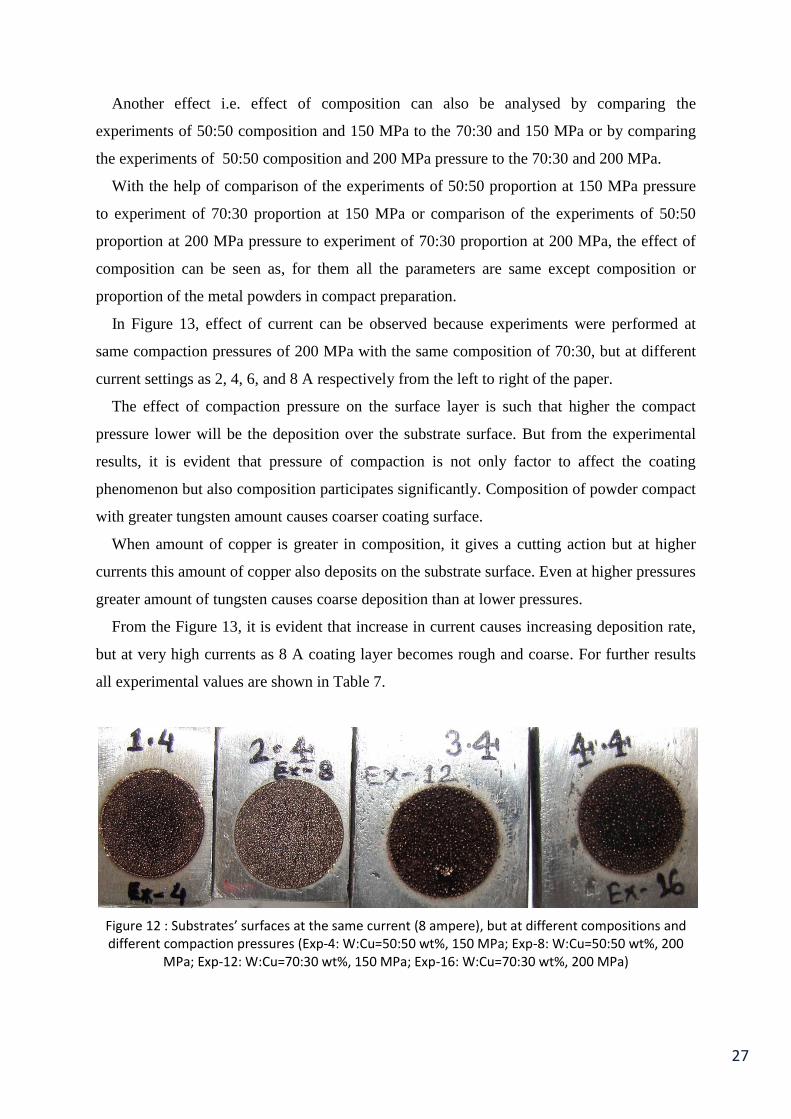
Figure 12 : Substrates’ surfaces at the same current (8 ampere), but at different compositions and
different compaction pressures (Exp-4: W:Cu=50:50 wt%, 150 MPa; Exp-8: W:Cu=50:50 wt%,
200 MPa; Exp-12: W:Cu=70:30 wt%, 150 MPa; Exp-16: W:Cu=70:30 wt%, 200 MPa) ................. 27
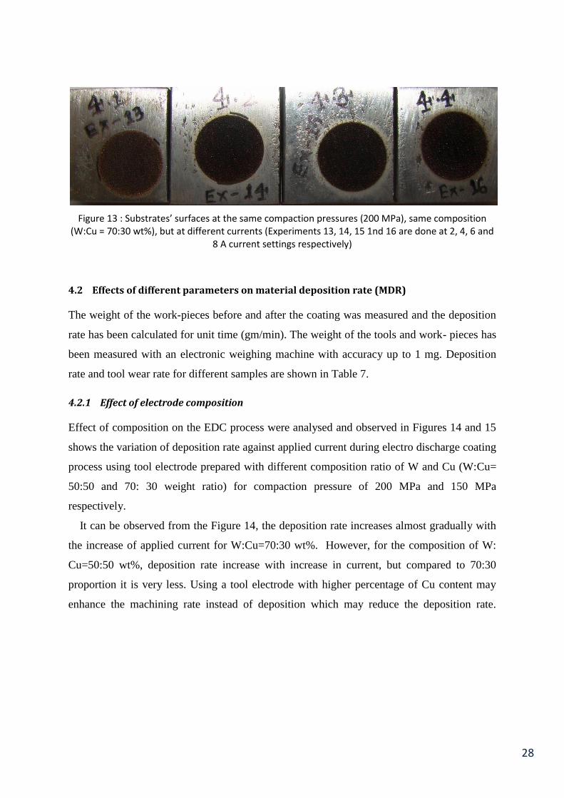
Figure 13 : Substrates’ surfaces at the same compaction pressures (200 MPa), same composition
(W:Cu = 70:30 wt%), but at different currents (Experiments 13, 14, 15 1nd 16 are done at 2, 4, 6
and 8 A current settings respectively) .......................................................................................... 28
Figure 14 : Deposition rate against applied current for different tool electrode prepared with
composition ratio of W:Cu = 50:50 and 70:30 by wt% and compact pressure of 200 MPa ......... 30
Figure 15 : Deposition rate against applied current for different tool electrode prepared with
composition ratio of W:Cu = 50:50 and 70:30 by wt% and compact pressure of 150 MPa ......... 30
Figure 16 : Deposition rate against applied current for different tool electrode prepared with
different compact pressure (150 Mpa and 200 MPa) and composition ratio of W: Cu =50:50
wt%. .............................................................................................................................................. 32
Figure 17 : Deposition rate against applied current for different tool electrode prepared with
different compact pressure (150 Mpa and 200 MPa) and composition ratio of W: Cu =70:30 wt%
...................................................................................................................................................... 32
Figure 18 : Tool wear rate against applied current for different tool electrode prepared with different
compact pressure (150 Mpa and 200 MPa) and different composition ratio of W: Cu i.e., W: Cu
= 50:50 and 70:30 by wt% ............................................................................................................. 33

Page vi
Figure 19 : SEM image of sample at 200 MPa compaction pressure, 4 A current and 50:50 (W:Cu)
proportion of metal powder by wt% ............................................................................................ 35
Figure 20 : SEM image of sample at 200 MPa compaction pressure, 4 A current and 70:30 (W:Cu)
proportion of metal powder by wt% ............................................................................................ 35
Figure 21 : SEM image of sample at 150 MPa compaction pressure, 6 A current and 50:50 (W:Cu)
proportion of metal powder by wt% ............................................................................................ 35
Figure 22 : SEM image of sample at 200 MPa compaction pressure, 6 A current and 50:50 (W:Cu)
proportion of metal powder by wt% ............................................................................................ 35
Figure 23 : SEM image of sample at 200 MPa compaction pressure, 2 A current and 70:30 (W:Cu)
proportion of metal powder by wt% ............................................................................................ 36
Figure 24 : SEM image of sample at 200 MPa compaction pressure, 4 A current and 70:30 (W:Cu)
proportion of metal powder by wt% ............................................................................................ 36
Figure 25 : XRD graph of sample with 50:50 proportion by wt% of W:Cu, 150 MPa and 8 A current . 37
Figure 26 : XRD graph of sample with 70:30 proportion by wt% of W:Cu, 150 MPa and 8 A current . 37
Figure 27 : XRD graph of sample with 50:50 proportion by wt% of W:Cu, 200 MPa and 8 A current . 38

Page vii
List of Tables
Table 1 : Properties of metal powders and mild steel as substrate ..................................................... 17
Table 2 : Parameters used for preliminary experimentation ............................................................... 18
Table 3 : Experimental results of preliminary experiments .................................................................. 19
Table 4 : Detailed parameters for P/M tool electrode preparation for final experiments .................. 21
Table 5 : Machining parameters .......................................................................................................... 23
Table 6 : Detailed experimental parameters ........................................................................................ 23
Table 7 : Experimental data for deposition rate and tool wear rate of EDC ........................................ 29
Table 8 : Readings of hardness’ and average hardness ........................................................................ 38
1
Chapter 1
Introduction
Surface coating is a process to alter the surface of engineering components to achieve
improvement properties such as high hardness, wear resistance, high-temperature resistance
and corrosion resistance, without making any significant change to bulk characteristics of the
structure.
Surface modification by material transfer during EDM has emerged as a key research area
in the last decade. Electric Discharge Coating (EDC) is one of the emerging coating
processes due to its ease, simplicity, reliability and cost effectiveness. Electric Discharge
Machining (EDM) is a non- conventional machining process, which is widely used for
machining various engineering materials. EDC is a coating process, which is reverse of the
EDM process. In the EDC a tool electrode made up of different materials (materials used for
electrode are the coating or alloying materials) and method of manufacturing the electrode is
powder metallurgy. Surface modification by EDM is one of the many methods to improve a
material work- piece‟s surface.
1.1 Various Coating Techniques
There are many surface modification methods through which a ceramic layer coating is
created on the surface of material and these coating techniques existing in the present
manufacturing world such as Physical vapour deposition (PVD), Chemical vapour deposition
(CVD), Electroplating, LASER coating, Electron-Beam Irradiation and Sputtering etc.
depending on their requirements.
1.1.1 Physical Vapour Deposition (PVD)
These processes are carried out in high vacuum and at temperatures in the range of 473-773
K. The particles to be deposited are transported physically to the work-piece, rather than by
chemical reactions, as in chemical vapour deposition.
In vacuum deposition, the metal to be deposited is evaporated at high temperatures in a
vacuum and deposited on the substrate, which is usually at room temperature or slightly
2
higher. Uniform coatings can be obtained on complex shapes with this method. In this
method of deposition a vacuum apparatus is required and maintaining complete vacuum is
not a easy deed.
1.1.2 Chemical Vapour Deposition (CVD)
This is a thermo-chemical process. In this process a thin-film is formed as a result of
reactions between various gaseous phases and the heated surface of substrates within the
CVD reactor. In a typical application, such as for coating cutting tools with titanium nitride
(TiN), the tools are placed on a graphite tray and heated to 1223-1323 K in an inert
atmosphere. Titanium tetrachloride (a vapour), hydrogen, and nitrogen are then introduced
into the chamber. The resulting chemical reactions form a thin coating of titanium nitride on
the tool‟s surfaces. Coatings obtained by CVD are usually thicker than those obtained via
PVD. In this method a very complicated coating environment is to be maintained, more
precisely an inert gas atmosphere. By virtue of this limitation, this process is limited to small
part sizes.
1.1.3 Plasma arc coating
This is the technique for spraying ceramic coatings for high temperature and electrical-
resistance applications. Powders of hard metals and ceramics are used as spraying materials.
Plasma-arc temperatures may reach 15,273 K, which is much higher than those obtained
using flames. Typical applications are nozzles for rocket motors and wear-resistant parts. In
this technique, temperature of spraying is very high and the materials, which are to be coated,
must withstand high temperatures.
1.1.4 Sputtering
In sputtering, an electric field ionizes an inert gas (usually argon). The positive ions bombard
the coating material (cathode) and cause sputtering (ejecting) of its atoms. These atoms then
condense on the work-piece, which is heated to improve bonding. In sputtering technique of
coating, maintenance of inert gas environment and at the time of bombardment/spraying,
control over the dispersion of coating materials‟ ions are very complicated factors to control.
1.1.5 Electroplating
In this process work-piece is plated with a different metal while both are suspended in a bath
containing a water-base electrolyte solution. The anode (metal to be deposited) metal ions are
3
discharged under the potential from the external source of electricity and then combine with
the electrolyte ions and are deposited on the cathode (work-piece). As the method is plated
from the solution, it has to be periodically replenished and the materials of plating must be
conductive. Moreover, electroplating is limited to coating the surfaces with materials like
gold, silver, and platinum etc., which cannot be used for tool and mould coatings.
1.1.6 LASER coating
Laser coating can be used to produce hard surfaces on a wide variety of engineering
materials. In this technique, hard ceramic powders like tungsten, titanium, tantalum, and
chromium is alloyed onto the surface of substrate. After preparing the work-piece surface
powder of one of the mentioned materials is dispersed over the substrate and then a high
energy laser beam of specified power, beam spot size and intensity is applied over the work-
piece substrate with a specific scanning speed. Due to the high kinetic energy of the laser
beam several thousand Kelvin temperature generates and the surface of work-piece melts and
mixed with the dispersed powder of the surface. By this procedure alloying of the surface
occurs. The process occurs at high speed, so little distortion of the surface and due to high
heating of the work-piece residual stresses (compressive) are left on the surface.
1.1.7 Electron-beam Irradiation
This process is similar to laser coating, where instead of using a high energy beam of laser,
high energy beam of electrons is used. Charged particles can be focused and directed by
means of electromagnetic controls. Electrons cannot travel in air, so the entire operation must
be performed in a high vacuum, and this is the major limitation of this process.
1.1.8 Electrical discharge coating (EDC)
EDC is a coating technique in which tool electrode manufactured by powder of materials,
such as Ti, W, Ta, Cr etc. The tool electrode is made by powder compaction in power press at
certain pressures. Maintaining the tool as anode and work-piece as cathode, in the presence of
dielectric fluid, material is decomposed from the tool electrode and compiled over the work-
piece surface in several minutes.
In this method of coating, there is no need of vacuum apparatus, or any special apparatus
with complicated set-up. Simple EDM set-up could be used to deposit coating and by
selecting coating parameters carefully and appropriately, thickness and coating characteristics
can be controlled.

4
1.2 Advantages of Electric Discharge Coating
In the manufacturing work-shops, several materials are used as cutting tool, mould and
pattern materials, forging dies and forming materials, shear materials etc. These materials
must have superior qualities than machining or job materials. Different properties on
materials impart by coating techniques. Even though there are several methods of coatings,
but EDC method has its own surplus advantages over the others.
PVD & CVD are widely used in cutting tools can improve the whole surface finish and the
performance of the materials, but these methods of coating required special apparatus such as
vacuum chamber. The coating area and thickness of coating layer is limited and cannot be
controlled as well. Due to these reasons the above processes do not find wide application in
tool and mould workshops.
The major advantage of EDC is that, it does not require any complicated apparatus‟ or
equipments like other coating techniques. With only an ordinary EDM machine tool, hard
ceramic layer can be formed easily on the work-piece. In EDC process, ceramic layer can be
provided in the different places of the work-piece with different areas of coating. Unlike the
other coating techniques, EDC provides a well controlled thickness of coated layer and the
coating speed is comparatively fast.
The range of material is used by the EDC method is wide, and the operation is very simple,
so this method has better application prospects. The fact that EDC reduces the cost of using
pure and entire amount of materials like Ti, W, Cr etc. and only a layer of these materials is
used for surface alloying.
EDC provides higher degree of hardness on the materials‟ surfaces (depending on the
coating material used), the hardness minimally increased by 2 to 4 times or even higher. The
alloying material sometimes fills the micro-voids of the work piece surface and surface
texture becomes improved. Wear resistance of the coated substrate surface has also been
enhanced several times and the surface integrity improves.
The above reasons are sufficient and postulate for the success of EDC method, its
worldwide acceptance and its wide applications in industries such as tool and mould
workshops.
1.3 Applications of EDC
EDC is used worldwide because of its simplicity, less cost of operation, satisfactory results
and easy set-up. With a general set-up of EDM machine, coating can be done. Some of the

5
major applications of EDC are as follows:
Roll texturing
This is a specific application of EDC process and popularly known as Electric Discharge
Texturing (EDT). In EDT process a roll is mounted and spins about its axis, then powder
metallurgy compact of Ti/W/Cr is set on servo-control. Roll rotates and sparking between the
roll and P/M compact disintegrates powder of harder material from the tool electrode and
compiles over the roll with integration of dielectric carbides.
Tool, die and mould
The major application of EDC is in tool and mould preparation work-shops. As the tool and
moulds should be of hard materials with high corrosion resistance, EDC provides the surfaces
of same properties and by virtue of these qualities EDC becomes very much favourite method
of coating for tool, die and mould making firms.
Industrial applications
EDC is used in tool, die and mould making industries and in aerospace applications. In
aerospace industries light weight and quality of metal used is very high, so EDC is applied in
different forms and provides these characteristics in lower costs.
1.4 Basic mechanism of EDC
EDC is the reverse method of EDM. In EDM metal is removed from the material of work-
piece or substrate and washed away by dielectric fluid‟s flushing, however in EDC the
material of tool electrode is decomposed from the tool and deposited over the substrate. Fig.
1 shows the principle of EDC. The electrodes employed are generally produced by powder
metallurgy (P/M) route, in order to achieve the necessary combination of operating
characteristics. In general, material like Ti, W, Ta with some binder materials like Co, Cu,
etc. are used as tool compact. The tool electrode compacts made from the powder
compaction method uses as tool electrode because it enables the forming of loose metal
powders into required shapes with sufficient strength. However during electro discharge
loose powder can easily come out from tool electrode and deposit on the work piece. In
general, compaction is done without the application of heat. Specific type hydrocarbon i.e.
transformer oil or kerosene are used as dielectric during the process.

6
The tool electrode which is manufactured by P/M technique connected to anode and work-
piece (on which coating is to be done) is selected as cathode in electro discharge machine
(polarity opposite to the electrical discharge machining).
During EDC process a spark is generated between work piece and tool and due to negative
polarity, evaporation of the anode is higher than the cathode. This evaporated tool material
after the melting rushes towards the cathode (work-piece/substrate) and deposited over the
surface. By setting the different parameters of coating thickness of the layer with some more
characteristics can be altered. During EDC process Ti, W or other metallic materials used as
electrode form a kind of hard carbide such as TiC or WC through chemical reaction between
worn electrode material and the carbon particles decomposed from the hydrocarbon fluid
under high temperature. The carbide is piled up on the work-piece and produces a hard layer
in specified time. The parameters should be controlled in such way that the cutting rate of the
work-piece must be lower than the wear rate of electrode.
Figure 1 : Basic mechanism of Electro-discharge processing
A wide range of powders with alternative compositions can be used for the manufacture of
tool electrodes. These tend to be materials which can form / transfer hard particles such as
carbides and may incorporate a secondary binder phase, e.g. WC/Co, TiC/WC/Co, W/Cr
C/Cu, etc. By using electrodes made from different materials, the possibility exists to
„engineer‟ one or more alloyed layers (which may be functionally graded) with different
mechanical properties. The compacting and sintering conditions under which the P/M
electrodes are produced greatly affect their performance.
7
1.5 Different types of EDC
Furutani et al. [1] classified the surface modification in the EDM process into four types;
{a} EDC by green powder compact electrode
In this technique of EDC, there are mainly two parts of process; firstly we have to make a
powder compact tool electrode and this electrode is used as anode in EDM machine tool.
Figure 1 shows this type of arrangement of coating. Basic mechanism of this type EDC
described in previous section. Green compacted tool electrode EDC can be of two types;
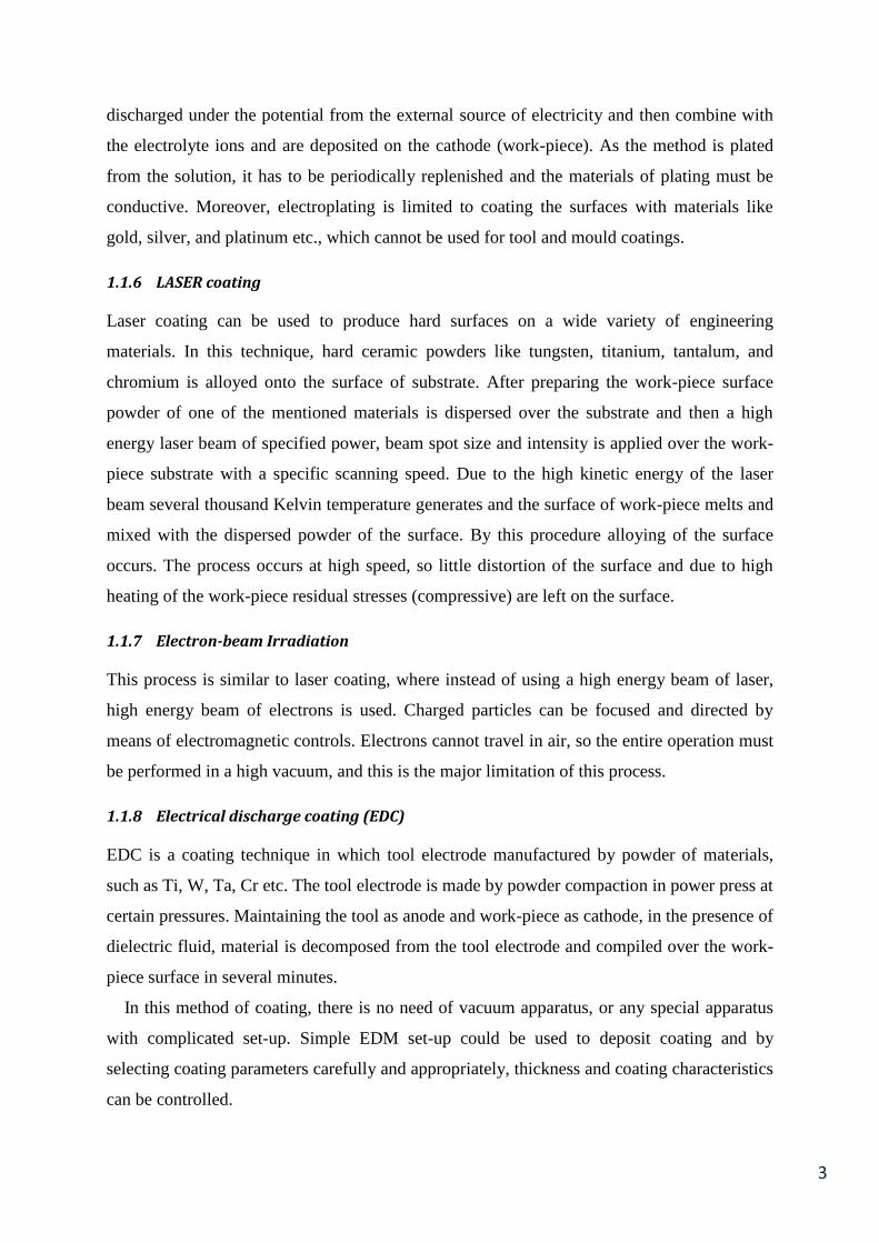
In first type, tool electrode material disintegrated and reacted with carbons (which is the
result of decomposition of hydrocarbon/dielectric fluid) and deposited over the surface of the
substrate. First type of green compacted tool electrode EDC mechanism is shown in Figure 2.
Figure 2 : Electrode and dielectric reaction kind EDC
(Ref. : Wang et al. [2])
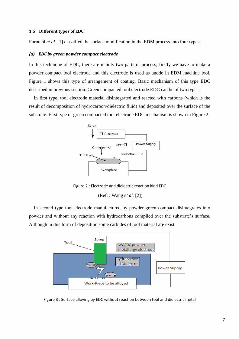
In second type tool electrode manufactured by powder green compact disintegrates into
powder and without any reaction with hydrocarbons compiled over the substrate‟s surface.
Although in this form of deposition some carbides of tool material are exist.
Figure 3 : Surface alloying by EDC without reaction between tool and dielectric metal

8
Second type of green compacted tool electrode EDC with principle and figure is shown in
Figure 3.
{b} Powder suspension EDC
In this method powder of desired coating material is mixed with dielectric fluid and electric
spark between copper electrode and substrate charged the powder of coating metal, in turn
deposition over the work-piece surface. Figure 4 shows the principle of EDC by powder
suspension.
This technique of EDC is very simple, but the real problem in this method is the quantity
of powder needed is large, which is not economical for small size work. Moreover the
parameters affecting the process are also more in number.
Figure 4 : Principle of powder suspension EDC
(Ref. : Janmanee and Muttamara [3])
{c} Wire brush or Bundle brush EDC
In this method of EDC a bunch of electrodes of thinner size (small diameter) of coating
material are stacked together to make a electrode of large diameter. This pile in electrode is
used for deposition in EDM machine tool. Figure 5 shows the principle of this method.

9
Figure 5 : Wire brush EDC
{d} Solid electrode EDC
In this EDC technique, a solid electrode of silicon or some copper metal is used for coating
and the deposition of electrode material over the surface is done by the ordinary EDC
process. Figure 1 shows the complete outline of this method when P/M compacted tool is
assumed as solid metal electrode.
1.6 Parameters of EDC
1.6.1 Electrode preparation parameters
The parameters used in tool electrode preparation are very significant in this research point of
view. Moreover appropriate values of these parameters help in imparting good qualities in
powder green compact tool electrode, which further enhances the quality of the coating. The
major parameters for tool preparation are:
Composition of tool electrode
Composition of powder or powder mixture is a very important factor, because it decides the
properties of the developed coating i.e. hardness, wear resistance, density, melting point,
thermal conductivity, specific heat etc. Sometimes two or more powders are mixed to
produce some composite coating which enhances the mechanical properties of the coating.

10
Mesh size or particle size
In compaction, if mesh size increases particles of compact squeezed properly and in turn
occurs a well compacted compact and due to these reasons mesh size is a very important
parameter of powder used for preparing the green compacted electrode.
Compaction pressure
This is the most valuable parameter, when preparing a powder compact. Depending on the
size of the die the loads in tons are calculated and compact is prepared. Higher the
compaction pressure, higher will be the bonds between the particle and compact will be more
dense and with higher strength. However higher strength of compact sometimes reduces the
tool wear during EDC process and deposition rate decreases.
Sintering temperature
Sometime to enhance the strength of the compact sintering is done. If sintering temperature
exceeds or reached up to the melting or recrystallization temperature of metal‟s powder, some
properties of the material change. High sintering temperature refines and annealed the grains,
and compact becomes hard.
1.6.2 EDM parameters
Parameters applicable in EDC process have very specific effects on the machining/coating of
the work-piece surface. The major EDM parameters which affect the EDC process are as
follows:
Polarity
Polarity refers to the direction of current flow through the circuit. Polarity can be positive or
negative depending on the flow i.e. if, in EDM, tool electrode is set at positive (anode) and
work-piece is at negative (cathode) called reverse polarity and vice-versa is called straight
polarity. Anode of circuit melts faster than cathode and due to this reason in EDC process
generally reverse polarity is used.
Current
The current (average) is the average of the amperage in the spark gap measured over a
complete cycle of machining/coating process. By changing the current setting the
characteristics of process like machining in EDM, surface layer in EDC can be changed.

11
Theoretically average current can be measured by multiplying the duty cycle and the peak
current (maximum current available for each pulse from the power supply /generator).
Voltage
The voltage used is usually of 40 to 400 volts of a DC power source. An AC power source
can also be used if DC rectifier is coupled with it. The preset voltage determines the width of
the spark gap between the tip of the electrode and the work piece surface.
Duty factor
Duty factor is an important parameter in the EDM process and this is given by the following
relation;
Duty factor is important in respect of deciding the time of spark and the time the spark
terminates. High duty factor means the pulse on time will be higher and spark prevails for
longer time and process of EDM/EDC i.e. erosion of work-piece/erosion of tool electrode.
Pulse-on time
Electro discharge operation is done during pulse on time. The electrode spark gap is bridged,
current is generated between the work-piece surface and tool electrode and the work is
accomplished. Longer the spark is sustained more is the material removed from the electrode
in EDC. Higher the pulse on time means higher will be the duty factor causes fast erosion of
anode. In our set-up is half of the total pulse time.
Pulse-off time
While most of the machining takes place during the pulse on time, the pulse off time during
which the pulse relaxes and the re-ionization of the dielectric takes place. During the pulse
off time the temperature of inter-electrode gap drops and process efficiency increases
otherwise it would have been a failure due to drastic temperature between the tool and work-
piece. The pulse off time also governs the stability of the process or it leads to the erratic
behaviour of servo control process.
12
Chapter 2
Literature Review
Several research papers have been studied and analysed for the understanding of EDC
technique. Some of them are reviewed and described in the following paragraphs. Gangadhar et al. [4] observed that during electro-discharge machining (EDM) the
topography, metallurgical and physicochemical properties of the surface layer change
significantly. Under certain circumstances, the metal transfer from the tool electrode to the
machined surface is also appreciable. It has been found that, using suitable process
parameters, surface alteration for desired functional behavior is feasible by EDM. The
authors performed some experimentation using bronze compacts having 90% copper and
10% tin as tool electrode and mild steel as work-piece. It has also been found that, the metal
transfer from the tool electrode to the work surface can be enhanced using powder compact
tools with reverse polarity. The experiment was carried for 3 minutes with peak current range
of 2.3 to 18.0 amp and frequencies in the range 5- 80 kHz. The authors studied the metal
transfer from the tool electrode by cross-sectional examination, electron spectroscopy and X-
ray diffraction analysis of the work surface. The associated changes in the surface topography
are analyzed by SEM. Surface modification for desired functional behavior during electro-
discharge machining (EDM) was correlated by suitable selection of process parameters.
Shunmugan et al. [5] uses tungsten carbide compact as tool electrode and experimented on
HSS by EDM with reverse polarity. The tool used was of 10mm diameter and 20 mm length
prepared with 40%WC and 60% iron at a compaction pressure of 700 MPa. During EDM, the
duty factor and peak voltage were 70% and 120-130 V respectively. It has been found that
WC-coated HSS tools exhibit improved wear resistance even under the extreme pressure and
temperature conditions encountered in metal cutting. 25%-60% improvement in abrasive
wear resistance and 20%-50% reduction in cutting forces are observed with WC-coated HSS
tools. This investigation opens up the possibility of EDC for wear-resistant coating.
Samuel et al. [6] has been studied the performance of P/M electrodes on various aspects of
EDM operation. It has been found that, materials with high thermal and electrical

13
conductivity coupled with considerable mechanical strength can function as good electrodes.
The study revealed that P/M electrodes are technologically viable in EDM and that EDM
properties of these electrodes can be controlled by varying compaction and sintering
parameters. P/M electrodes are found to be more sensitive to pulse current and pulse duration
than conventional solid electrodes. Under certain processing conditions P/M electrodes can
cause material addition rather than removal.
Zaw et al. [7] suggested some electrode materials for electrical-discharge machining i.e.
graphite, copper, copper alloys, copper-tungsten, brass, silver-tungsten and steel. Materials
having good electrical and thermal conductivity with a high melting point are preferred to be
used for fabricating electrodes. Compounds of ZrB2 and TiSi with Cu at various
compositions are investigated for EDM electrodes by either solid-state sintering or liquid
phase sintering. The performance of this electrode is compared with the conventional
electrode materials such as Cu, Graphite, CuW.
Simao et al. [8] modify the surface of hardened AISI D2 Sendzimir rolls, by electrical
discharge texturing (EDT). It has been revealed that, by using powder metallurgy (PM) green
compact and sintered electrodes of TiC/WC/Co and WC/Co, life and performance of rolls
have been improved significantly. Analysis shows that Ti and W contained in the PM
electrodes, together with C decomposed from the dielectric medium made various
compounds which were transferred to the work-piece surface during sparking. An increase in
the roll white layer micro hardness was observed (up to 950 HK0.025) on employing sintered
TiC/WC/Co tool electrodes. This value was much higher than either that of the heat-treated
AISI D2 roll matrix or the measured typical roll white layer hardness by using conventional
tool electrodes.
Simao et al. [9] summarized the process as deliberate surface alloying of various work-
piece materials using EDM. The operations involving powder metallurgy tool electrodes and
the use of powders suspended in the dielectric fluid, typically aluminium, nickel, titanium,
etc. Following this, experimental results are presented on the surface alloying of AISI H13
hot work tool steel during a die sink operation using partially sintered WC / Co electrodes
operating in a hydrocarbon oil dielectric. An L8 Taguchi experiment was carried out to
identify the effect of key operating factors on output measures (electrode wear, work-piece
surface hardness, etc.). It has been found that with respect to micro-hardness, the percentage
contribution ratios (PCR) for peak current, electrode polarity and pulse on time were ~24, 20
14
and 19%, respectively. Typically, changes in surface metallurgy were measured up to a depth
of ~30 μm and increase in the surface hardness up to ~1350 HK0.025 observed.
Lee H.G. et al. [10] studied the surface alloying of titanium alloy i.e. gamma Ti-Al (Ti–
46.5Al–4(Cr, Nb, Ta, B)) and Ti alloy (Ti–6Al–4V) sheet during wire cutting using
deionised water as dielectric with nickel and copper wires. The authors further observed that
utilization of partially sintered powder metallurgy (PM) electrodes, where the binding energy
between grains is reduced as compared to fully dense products, can encourage surface
alloying. some textured and alloyed layers on the roll material were over 900HK0.025 when
using WC/Co electrodes as compared to surfaces produced with standard Cu/graphite tools of
500–740HK0.025.
Limitation of Physical Vapor Deposition (PVD) or Chemical Vapor Deposition (CVD)
with a carbon titanium (TiC) was highlighted, and an alternative method to improve cutting
tool life was studied by Moro et al. [11] namely electrical discharge coating (EDC). The
author deposited TiC coating on S45C (JIS) substrate material using tool electrode prepared
by semi-sintering of TiC powder at 900 oC for 1 hour. The experiment were carried out for 16
min with discharge current of 8 amps, Ton time of 8 µs, and duty factor as 5.9%. The relation
between a wear rate of an electrode and maximum thickness has been investigated.
Patowari et al.[12] performed EDC on steel substrate with W–Cu P/M sintered electrodes
having composition 75% tungsten and 25% Copper. Experimentation was carried out with
negative polarity and with Peak current in the range of 4- 12 amp, Pulse duration of 19 to 386
µs in different steps and Duty factor at lower Ton setting of 50% and at higher Ton setting of
70 %. Gap control between the tool and the workpiece is adjusted so that at around 40-45
volts throughout the processing time of 5 minutes. During the manufacture of electrode
compaction pressure were taken in the range of 120-300MPa, and sintering temperature 700
and 900 oC. The authors also made an attempt to model the process by artificial neural
networks. Two output measures, namely material transfer rate and average layer thickness,
have been correlated with different input parameters.
Kumar and Batra [13] investigated the surface modification by EDM method with
tungsten powder mixed in the dielectric medium. Peak current, pulse on-time and pulse off
time were taken as variable factors and micro-hardness of the machined surface was taken as
the response parameter. The machining process is carried out at a sparking voltage 135 V and
a peak current of 2, 4 and 6 amps. Pulse-on time and pulse–off time used during the
15
machining process were 5, 10, 20 µs and 38, 57, 85 µs respectively. The process was carried
out in commercial grade kerosene as dielectric and 10 minutes machining time in reverse
polarity condition. X-ray diffraction (XRD) and spectrometric analysis show substantial
transfer of tungsten and carbon to the workpiece surface. An improvement of more than
100% in micro-hardness has been observed. The authors also observe that the impact pressure
and high thermal stresses generated by the discharge produces the craters and micro cracks in
the machining surface.
Furutani et al. [1] classified the surface modification in the EDM process into four types.
The first type of surface modification gives a green compact electrode or semi-sintered
electrode, which is made from titanium carbide or tungsten carbide. The second type of
surface modification gives a wire brush or bundle wire electrode. The third type of surface
modification consists of a powder suspended in a dielectric fluid for the EDM process, which
serves mainly as a removal of material process. The fourth type of surface modification gives
a solid electrode for the EDM removal process such as a silicon electrode or a tungsten
carbide electrode.
Janmanee and Muttamara [3] experimented the surface modification of tungsten carbide
by electrical discharge coating (EDC) using a titanium powder suspension method of EDC.
The current and duty cycles were varied resulting in a change in the titanium coating layer
thickness. Analysis of the chemical composition using energy dispersive spectroscopy (EDS)
revealed that a titanium coating layer was formed on tungsten carbide substrate. The
microstructure of the surface was evaluated using scanning electron microscopy (SEM). It
has been found that, high concentration of carbon increases the amount of Ti and C
combination and TiC was formed, which enhanced the surface hardness of the coated layer
up to 1750 HV.
Wang et al. [2] have done the surface modification by electrical discharge coating with a
Ti powder green compact electrode. Approximately 20 microns of ceramic layer deposited on
the substrate (Fe) surface. The parameters of coating are taken as current varying from 2.2 to
10 ampere, discharge duration varying from 2 to 12 microseconds, duty factor as 5.88 %,
machining time as 18 min and machining area as 12 mm2. After the experimentation
composition, hardness and microstructure of the coated layer were analysed.
Hwang et al. [14] deposited coating of TiC on the surface of nickel by electric discharge
coating (EDC) using a multi-layer electrode. In this study bundle or wire brush method was
16
used for EDC compare the characteristics with conventional electrode. The experimental
results indicate elements of carbon with high concentration could increase the combination of
titanium (Ti) and carbon (C) to become titanium carbide (TiC), which enhance surface
hardness of the coated layer, decrease surface roughness, reduce formation of micro-cracks,
and enhance the stability of electric discharge and coating speed.
Aspinwall et al. [15] has been studied electrical discharge surface alloying of Ti and Fe
work-piece using different refractory powders. The experimentation was carried out by two
different techniques of EDC; in first method, TiC and WC powder compact were used as tool
electrode whereas in other method copper is used as electrode and, Ti and W powder is
suspended in the hydrocarbon dielectric.
2.1 Objective of the present work
A mixture of Tungsten (W) and copper (Cu) powder in different weight has been used to
prepare the green compact powder metallurgy (P/M) tool electrode. Using reverse polarity
(tool as anode and work-piece as cathode) in electro discharge machine and AISI 1020 mild
steel as work piece material a composite layer of WC-Cu has been deposited on the work-
piece. The objectives of the present work are as follows;
1. Main objective is to develop a hard, wear resistance coating of WC-Cu coating on
AISI 1020 mild steel.
2. Material transfer rate on changing the various parameters in EDM and powder
metallurgy compaction process such as current, compaction pressure, composition of
powder mixture has been studied.
3. The microstructure of the coating layer and the compounds present in the coating
were analyzed by SEM (Scanning Electron Microscope) and XRD (X-Ray
Diffraction) technique respectively.
4. The hardness of the coating was also being measured by Vickers‟ Micro hardness
Tester.

17
Chapter 3
Experimental planning and procedure
This part of project work includes properties of materials used in experiment such as
properties of work-piece, tool electrode powders, preparation of powder compacted green
electrode, preliminary experiment and final experimentation. 3.1 Properties of substrate and powder of tool electrode
For the present project work, two powders (W and Cu) are mixed and used for making tool
electrodes with different proportions. AISI 1020 mild steel is used as work-piece (substrate).
Properties of these materials are shown in the Table 1.
Table 1 : Properties of metal powders and mild steel as substrate
Material Density
(gm/cm3 )
Melting
point
temp.
(K)
Specific
heat
(J/kg K)
Thermal
conductivity
(W/m K)
Coefficient
of thermal
expansion
(*10-6/ K)
Particle
size
(microns)
Mesh size
Cu powder 8.97 1355 385 393 16.5 44 325
W powder 19.29 3683 138 166 4.5 44 325
Mild Steel 6.92 1644 490 20 12 - -
Experimentation of Electro discharge coating (EDC) has been done mainly in two steps;
(i) Green compact sintered powder metallurgy (P/M) tool preparation
(ii) Electro Discharge coating (EDC) with P/M tool on mild steel by using EDM
Prior to final experimentation some preliminary experiments have been conducted to find out
the range of processing parameters.

18
3.2 Preliminary experiment
For these experiments, four electrodes were made by powder metallurgy (P/M) method. Two
electrodes were made up of pure copper and other two with the mixture of copper and
tungsten. The mixture proportions taken are 50:50 by weight percentage. After calculation it
is found the for 10 mm diameter and 5 mm height, pure copper electrodes require 8 to 10 gm
of copper powder and for the same dimensions mixture (50:50 by weight) requires 2.5 to 3
gm of powders of each copper and tungsten powder for mixed tool compacts. Using ceramic
mortar and pestle powders of tungsten and copper were mixed properly. Compaction was
done with a power press of capacity 15-25 tons maximum pressure. Compaction die of 10
mm diameter was used and electrodes were prepared. Initially 250 MPa compaction pressure
was used to prepare powder compact tool electrode. Table 2 shows the parameters used and
their values for this preliminary experimentation. In Figures 6 and 9 green powder compact
tool electrode tips prepared by P/M method are shown.
Table 2 : Parameters used for preliminary experimentation
Parameters Available values
Dimensions of compact 10 mm diameter & 5 mm height
Compaction pressure 250 MPa (2 tons)
Holding/ Stand up time 2 min.
Powder proportion 50:50 weight %
Figure 6 : P/M compacted tool electrode tips
Due to the fact that large height of powder compact with the given compaction pressure
(which is very low) is prone to yield and amount of powder required for heighted tool compact
tool electrode extensions were used. Extensions of tool electrodes with proper dimension have
been prepared with mild steel to accommodate in the EDM machine and P/M green compacted

19
electrodes are brazed on the tip of the extensions by gas brazing method with silver braze.
Figure 7 shows the extension rod of mild steel and brazed tool electrode.
Figure 7 : Mild steel tool extension and brazed tool electrode ready to mount on EDM
For the preliminary experiments, pure copper and copper and tungsten mixed (50:50 by wt%)
P/M tool at 250 MPa compact pressure have been prepared. The fixed parameters of coating
were selected as voltage of 40 volt, duty factor as 50 % and operating time of 20 minutes.
Table 3 shows the different experimental condition and obtained results of the preliminary
experimentation.
Table 3 : Experimental results of preliminary experiments
Exp.
No.
Tool material polarity Ip
Amp
Ton
µs
Remarks
1 Pure Cu +Ve 4 100 No deposition (machining)
2 Pure Cu -Ve 4 150 Very less deposition at the edges with
machining
3 Pure Cu -Ve 8 200 Very less deposition at the edges with
higher machining
4 W: Cu
(50:50 wt%)
-Ve 4 100 Deposition on substrate
5 W:Cu
(50:50 wt%)
-Ve 8 100 Deposition on substrate as well as very less
machining
3.2.1 Outcomes of preliminary experiments
When experiments were performed by the prepared green compacted electrode of pure Cu
deposition of the electrode material on the substrate surface did not take place, instead
machining on the substrate surface observed.
20
In the case of mixed powder tool electrode (W: Cu =50:50 wt %) very small amount of
coating has been observed and there also cutting of work-piece took place. The above results
are evident by visual inspection of the sample and measured weight of the work piece and
tool before and after experiments.
Following are the outcomes of preliminary experiments, which bound us for further
changes in process parameters;
1. The compaction pressure (250 MPa) selected for powder compaction is too high and
this restricts the disintegration of powder from the tool at the time of coating.
2. Higher amount of copper in powder compact causes the properties of cutting the
material as Cu is one of the best cutting tool material in EDM process. So Cu impairs
the coating phenomenon significantly.
3. Only higher current settings and larger pulse on time help to coat the substrate to
some extent, but if compaction pressure is high or amount of Cu is more, cutting of
substrate surface will also be rigorous.
4. Brazing temperature at the time of joining the extension rod with powder compact
was a worrying factor, because the highest temperature of brazing by silver and its
alloys goes typically up to 895 K-1425 K (average temperature of 1160 K), which is
almost same as the sintering temperature of Cu powder (even though the sintering
temperature of W is 2675 K). Due to this fact partial sintering of compact takes place
and it becomes harder and difficult to disintegrate.
3.3 Final experiment
From the feedback of the preliminary experiments final experiments has been performed.
3.3.1 Electrode preparation
In this set of experiment four tool electrodes of composition 50:50 and 50:70 (Cu:W by
weight percentage) at two different pressures 150 MPa and 200 MPa prepared by the powder
metallurgy process. The diameter of the tool electrode is kept 15 mm and height as 10 mm.
Method is similar as described in 3.2. Details of the electrode preparation parameters are
given in Table 4. Figure 8 shows the flow chart of P/M electrode preparation method.

21
Table 4 : Detailed parameters for P/M tool electrode preparation for final experiments
Proportions of powders (W:Cu) 50:50 and 70:30 wt.%
Compaction pressures 150& 200 MPa
Dimensions of compact 15 mm diameter & 10 mm height
Holding / Stand- up time 2 min
Figure 8 : Flow chart of manufacturing P/M product
As in the process of powder compaction the powder is mixed with desired additives to
make bonding between the particles, but in the present study copper itself works as a binding
material for tungsten powder. No blending is used and sintering of compact is not done due to
the fact that sintered compact is somewhat strengthen the compact and restrict decomposition
of powder during electro discharge coating process.
Figure 9 : P/M compacted tool electrode tips prepared with various % of W and Cu and with different compact pressure
Green powder compact electrode prepared with W: Cu=70:30 wt % and compact pressure
200 MPa (number 1) and 150 MPa (number 2) respectively, W: Cu=50:50 wt % and 200

22
MPa pressure (number 3) are shown in Figure 9. Another compact prepared with W:
Cu=50:50 wt % and 150 MPa compact pressure is not shown in the figure. Extensions of tool
electrodes have been prepared from mild steel rod with required dimension to accommodate
in the EDM machine and P/M green compacted electrodes are brazed on the tip of the
extensions.
Substrate preparation
AISI 1020 mild steel of size 20 mm x 20 mm x 5 mm has been taken as Work- piece for the
present experiments. Total 16 numbers of work-pieces have been prepared. At first, from a
strip of mild steel of 5 mm thickness, pieces of 20 mm*20 mm cut and then the burrs of edges
removed by using the electrical grinding machine. After grinding edges surfaces of the work-
pieces smoothen by the abrasive paper (emery paper) of different grades (grade of number 80
to120 in different steps).
Before going for experiment work-piece was washed with alcohol/acetone liquid, dried up
and then dipped into the EDM fluid so that its pores filled and merged with that fluid. By
dipping the substrate in EDM fluid, its weight does not affect the weight of substrate after
coating as its pores already filled with the fluid.
3.3.2 Electro-discharge coating process
In second step EDC process performed using EDM machine. The tool electrode and work-
piece are immersed in a dielectric medium. In order to deposit the material over the work
surface by erosion of the tool electrode, tool electrode is kept as anode and work piece as
cathode (reverse polarity). By using different type of tool electrode prepared with different
composition and compact pressure experimentation have been performed.
Figure 10 shows the schematic arrangement of EDC process used for the present
experiment. Electro discharge machine (ELECTRONICA LEADER-1, ZNC‟s version
ELEKTRAPULS PS 50 ZNC EZY LOGIC ) has been used for the present experiment.
Prepared electrode after brazing with tool extension is mounted on the EDM‟s servo control
unit and substrate on the work table with the fixture of suitable height.
To study the effect of peak current on deposition rate experimentation have been done with
4 different current setting i.e 2, 4, 6 and 8 amp, by keeping the other EDM parameters like
TON, TOFF, duty factor, gap voltage constant. Table 5 shows the parameters, which are
common for all experimental setups. The details of experimental condition are shown in
Table 6.

23
Table 5 : Machining parameters
Voltage 40 V
Duty Factor 50%
Ton 100 µs
Time of experimentation 20 min
Table 6 : Detailed experimental parameters
Tool
No.
(Cu:W)
wt%
Pressure
(MPa)
Exp.
No
Ip
(Amp)
1 50:50 150 1 2
2 4
3 6
4 8
2 50:50 200 5 2
6 4
7 6
8 8
3 30:70 150 9 2
10 4
11 6
12 8
4 30:70 200 13 2
14 4
15 6
16 8

24
Figure 10 : Electro-discharge coating process
Figure 11 : Experimental set-up of EDM machine tool
25
Measurement of deposition rate
After preparing the EDM and making all necessary arrangements, initial weight of substrate
and tool electrode is measured. After the experiment final weight of substrate and tool
electrode is measured. Difference between the weights of substrate after and before
experiment represents the amount of material deposited on the substrate surface. Deposition
rate has been calculated by dividing the deposition with total experimental time. Similarly
tool wear rate has been calculated considering weight of tool electrode before and after the
experiment.
3.3.3 Preparation of sample for SEM, XRD and micro hardness analysis
After the experiments substrate has to be prepared for further analysis such as SEM, XRD
and Micro Hardness Test (Vickers‟ Hardness Test).
Preparation of substrate for SEM is very crucial, because for measuring the height of the
ceramic layer (deposited on the substrate surface), the cross section must be super finished
(mirror like surface) and cut in small piece to accommodate in the SEM machine‟s chamber.
At first, coated samples are cut at the cross section with the help of hacksaw. Then the cross
section was ground to some extend to remove the burrs. Care should be taken during cutting
and grinding so that edge of the coated surface not damaged. After grinding the cross section
was polished with 120 grade abrasive paper. Then the surface of the cross section was
polished with finer grades polishing paper graded 1, 2, 3, and 4 sequentially. After that the
cross section of the polished surface was cleaned with acetone.
For XRD as such no specific sample preparation is required, as data for XRD is collected
only from the surface of the coating layer.
For micro hardness testing, top surface of the coating are polished with fine grade
polishing paper so that indentation could be visible under Vickers‟ micro-hardness tester.

26
Chapter 4
Results and Discussions
This chapter contains all the results and their relevant discussions of the experimentation
conducted by EDM machine tool on AISI 1020 M.S. work-piece with powder compact
electrode of tungsten and copper.
4.1 Experimental results
The developed coating of WC-Cu on AISI 1020 mild steel are analysed by X-Ray Diffraction
(XRD) technique for phase identification, Scanning Electron Microscopy (SEM) for study the
microstructure of the coated surface and Vickers‟ Micro hardness Tester for knowing the
hardness value of the coated surface respectively.
The effects of composition (W and Cu ratio) and compaction pressure of the tool electrode
and peak current during electro discharge process were observed and analysed specifically for
deposition rate, tool wear rate, micro-structure of the coating and different phases formed on
the coating surface in EDC.
Figures 12 and 13 shows the WC-Cu coated AISI 1020 steel substrate EDC coating. Suffix
Ex-number on the sample represent the experiment number as per Table 7.
In Figure 12, the effect of compaction pressures and composition can be understood by
comparing the experiments of 50:50 composition and 150 MPa (Exp.-4), 50:50 composition
and 200 MPa pressure (Exp.-8), 70:30 and 150 MPa (Exp.-12), and 70:30 and 200 MPa
(Exp.-16).
The effect of the compaction pressures can be visualized by the experiments of 50:50
proportion and 150 MPa pressure with 50:50 proportion and 200 MPa, because these are
done at same current settings i.e. on 8 ampere. The same effect can also be observed by the
comparison of experiments of 70:30 and 150 MPa with the experiment 70:30 and 200 MPa.
27
Another effect i.e. effect of composition can also be analysed by comparing the
experiments of 50:50 composition and 150 MPa to the 70:30 and 150 MPa or by comparing
the experiments of 50:50 composition and 200 MPa pressure to the 70:30 and 200 MPa.
With the help of comparison of the experiments of 50:50 proportion at 150 MPa pressure
to experiment of 70:30 proportion at 150 MPa or comparison of the experiments of 50:50
proportion at 200 MPa pressure to experiment of 70:30 proportion at 200 MPa, the effect of
composition can be seen as, for them all the parameters are same except composition or
proportion of the metal powders in compact preparation.
In Figure 13, effect of current can be observed because experiments were performed at
same compaction pressures of 200 MPa with the same composition of 70:30, but at different
current settings as 2, 4, 6, and 8 A respectively from the left to right of the paper.
The effect of compaction pressure on the surface layer is such that higher the compact
pressure lower will be the deposition over the substrate surface. But from the experimental
results, it is evident that pressure of compaction is not only factor to affect the coating
phenomenon but also composition participates significantly. Composition of powder compact
with greater tungsten amount causes coarser coating surface.
When amount of copper is greater in composition, it gives a cutting action but at higher
currents this amount of copper also deposits on the substrate surface. Even at higher pressures
greater amount of tungsten causes coarse deposition than at lower pressures.
From the Figure 13, it is evident that increase in current causes increasing deposition rate,
but at very high currents as 8 A coating layer becomes rough and coarse. For further results
all experimental values are shown in Table 7.
Figure 12 : Substrates’ surfaces at the same current (8 ampere), but at different compositions and different compaction pressures (Exp-4: W:Cu=50:50 wt%, 150 MPa; Exp-8: W:Cu=50:50 wt%, 200
MPa; Exp-12: W:Cu=70:30 wt%, 150 MPa; Exp-16: W:Cu=70:30 wt%, 200 MPa)
28
Figure 13 : Substrates’ surfaces at the same compaction pressures (200 MPa), same composition (W:Cu = 70:30 wt%), but at different currents (Experiments 13, 14, 15 1nd 16 are done at 2, 4, 6 and
8 A current settings respectively)
4.2 Effects of different parameters on material deposition rate (MDR)
The weight of the work-pieces before and after the coating was measured and the deposition
rate has been calculated for unit time (gm/min). The weight of the tools and work- pieces has
been measured with an electronic weighing machine with accuracy up to 1 mg. Deposition
rate and tool wear rate for different samples are shown in Table 7.
4.2.1 Effect of electrode composition
Effect of composition on the EDC process were analysed and observed in Figures 14 and 15
shows the variation of deposition rate against applied current during electro discharge coating
process using tool electrode prepared with different composition ratio of W and Cu (W:Cu=
50:50 and 70: 30 weight ratio) for compaction pressure of 200 MPa and 150 MPa
respectively.
It can be observed from the Figure 14, the deposition rate increases almost gradually with
the increase of applied current for W:Cu=70:30 wt%. However, for the composition of W:
Cu=50:50 wt%, deposition rate increase with increase in current, but compared to 70:30
proportion it is very less. Using a tool electrode with higher percentage of Cu content may
enhance the machining rate instead of deposition which may reduce the deposition rate.

29
Table 7 : Experimental data for deposition rate and tool wear rate of EDC
Exp.
No.
Pressure
(MPa)
Current
(amp.)
Work-Piece weights
Deposition
(gm)
Deposition
rate
(gm/min) Tool weights
Tool wear
(gm)
Tool wear rate
(gm/min)
Before
Experiment
(AW)
After
Experiment
(BW) (BW-AW) (BW-AW)/20
Before
Experiment
(CT)
After
Experiment
(DT) (CT-DT) (CT-DT)/20
1 150 2 26.118 26.12772 0.00972 0.000486 115.2454 115.213 0.0324 0.00162
2 150 4 23.793 23.81223 0.01923 0.0009615 115.27915 115.183 0.09615 0.0048075
3 150 6 23.328 23.358 0.03 0.0015 115.103 114.843 0.26 0.013
4 150 8 17.718 17.835 0.117 0.00585 114.843 112.071 2.772 0.1386
5 200 2 19.405 19.408 0.003 0.00015 114.307 114.298 0.009 0.00045
6 200 4 20.801 20.81411 0.01311 0.0004 114.36357 114.298 0.06557 0.0032785
7 200 6 22.148 22.116364 0.01564 0.000782 114.4105 114.241 0.1695 0.008475
8 200 8 18.323 18.353 0.03 0.0015 114.09 113.102 0.988 0.0494
9 150 2 24.683 24.693 0.01 0.0005 118.303 118.246 0.057 0.00285
10 150 4 27.705 27.75 0.045 0.00225 122.797 122.54 0.257 0.01285
11 150 6 28.221 28.367 0.146 0.0073 122.54 121.335 1.205 0.06025
12 150 8 27.742 28.123 0.381 0.01905 121.335 118.308 3.027 0.15135
13 200 2 25.949 25.996 0.047 0.00235 137.996 137.841 0.155 0.00775
14 200 4 27.585 27.705 0.12 0.006 137.841 136.891 0.95 0.0475
15 200 6 27.112 27.341 0.229 0.01145 136.891 134.868 2.023 0.10115
16 200 8 26.757 27.19 0.433 0.02165 134.868 131.33 3.538 0.1769

30
2 3 4 5 6 7 8
0.000
0.005
0.010
0.015
0.020
De
po
sitio
n r
ate
(g
m/m
in)
Peak Current (Amp)
Tool compact pressure= 200 MPa
W:Cu=50:50
W:Cu=70:30
Figure 14 : Deposition rate against applied current for different tool electrode prepared with composition ratio of W:Cu = 50:50 and 70:30 by wt% and compact pressure of 200 MPa
2 3 4 5 6 7 8
0.000
0.005
0.010
0.015
0.020
De
po
sitio
n r
ate
(g
m/m
in)
Peak Current (Amp)
Tool compact pressure 150MPa
W:Cu=50:50
W:Cu=70:30
Figure 15 : Deposition rate against applied current for different tool electrode prepared with composition ratio of W:Cu = 50:50 and 70:30 by wt% and compact pressure of 150 MPa

31
Similar phenomenon can also observed for the experiments performed using tool electrode
prepared with W: Cu= 50:50 and 70: 30 weight ratio and compact pressure of 200 MPa as
shown in Figure 14. In Figure 15, it is evident that the deposition rates are almost same at 2 A
current for both the compositions. For the composition of 50:50 deposition rate increases with
current up to 6 A gradually, but between 6 to 8 A material deposition rate it shoots up. On the
other hand 70:30 compositions give higher deposition rate with increase in current. In 70:30
proportion with increase in current graph shoots up every time, when current setting changes.
4.2.2 Effect of compaction pressures
In Figure 16 and 17, deposition rate against applied current has been plotted for different tool
electrode prepared in different compact pressure (150 Mpa and 200 MPa) by using different
composition ratio of W and Cu i.e, 50:50 and 70:30 by wt%.
From the figure 16, it is revealed that for tool electrode prepared with 150 MPa compact
pressure, deposition rate linearly increases from 2 to 6 amp, but from 6 to 8 amp deposition
rate shoots up due to the fact that it is compacted at lower compaction pressure and moreover
with increase in current tool compact becomes coarser and due to this, large number of
powder particles disintegrate from the tool and compiled on the substrate surface. However
the coating at higher current and lower compaction pressure becomes very rough and brittle
in nature.
Figure 16 also shows that for tool electrode prepared with 200 MPa compact pressure, with
increase in current deposition rate also increases, but the rate of deposition is less. This is
mainly due to higher compaction pressure of the tool electrode which restricts the
decomposition during the electric discharge coating process and reduces the deposition rate.
However, when current setting changes to higher values deposition rate increases
comprehensively.
Similar study of Figure 17 shows that deposition rate increase with increase in current with
respect to compact pressure change. Study of this graph contradicts pervious theories related
to deposition rate, current, composition and compaction pressure, which were extracted from
the graphical results, because deposition rate is more and increases rapidly for higher
compaction pressure (200 MPa) when compared to lower compaction pressure (150 MPa).
This may be due to the combined effect of lower amount of copper in the tool electrode at
higher compact pressure.
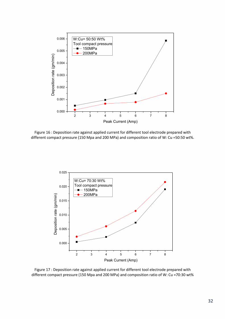
32
2 3 4 5 6 7 8
0.000
0.001
0.002
0.003
0.004
0.005
0.006
De
po
sitio
n r
ate
(g
m/m
in)
Peak Current (Amp)
W:Cu= 50:50 Wt%
Tool compact pressure
150MPa
200MPa
Figure 16 : Deposition rate against applied current for different tool electrode prepared with different compact pressure (150 Mpa and 200 MPa) and composition ratio of W: Cu =50:50 wt%.
2 3 4 5 6 7 8
0.000
0.005
0.010
0.015
0.020
0.025
De
po
sitio
n r
ate
(g
m/m
in)
Peak Current (Amp)
W:Cu= 70:30 Wt%
Tool compact pressure
150MPa
200MPa
Figure 17 : Deposition rate against applied current for different tool electrode prepared with different compact pressure (150 Mpa and 200 MPa) and composition ratio of W: Cu =70:30 wt%

33
4.3 Effects of different parameters on tool wear rate (TWR)
Figure 18 shows the tool wear rate ( TWR) against applied current for different tool electrode
prepared with different compact pressure (150 Mpa and 200 MPa) and different composition
ratio of W: Cu i.e., W: Cu = 50:50 and 70:30 by wt%.
2 3 4 5 6 7 8
0.0
0.5
1.0
1.5
2.0
2.5
3.0
3.5
4.0
T
oo
l w
ea
r ra
te (
gm
/min
)
Current (Amp)
W:Cu=50:50,150MPa
W:Cu=50:50,200MPa
W:Cu=70:30,150MPa
W:Cu=70:30,200MPa
Figure 18 : Tool wear rate against applied current for different tool electrode prepared with different compact pressure (150 Mpa and 200 MPa) and different composition ratio of W: Cu i.e., W: Cu =
50:50 and 70:30 by wt%
From the graph it has been found that, parameters affecting the TWR are same as
parameters affecting the deposition rate. For understanding the effects of different
parameters, we would be using references of graphs as shown in Figure 18 with the different
graphs.
4.3.1 Effect of electrode composition
According to the Figure 18, graph lines of 50:50 proportion at 150 MPa pressure with 70:30
proportion at 150 MPa pressure or 50:50 proportion at 200 MPa with 70:30 proportion at 200
MPa pressure can be compared, because these are at same compaction pressures and different
powder proportions. TWR is more for the compact with greater amount of tungsten and lesser
amount of copper, because lesser the amount of copper higher will be the deposition and
lower will be the cutting. With highest copper amount i.e. 50:50 at highest compaction
pressure i.e. 200MPa, TWR found out lowest and with 70:30 proportion, TWR is maximum
at 200 MPa compaction pressure. The reason of more TWR even at higher compaction

34
pressure has been explained in section 4.2.1 of the same thesis work. All comparison is done
on the grounds of increase in current‟s amount as discussed in MDR.
4.3.2 Effect of compaction pressures
Effects of compaction pressures can be visualized by comparing the graph lines of 50:50
proportion at 150 MPa pressure with 50:50 proportion at 200 MPa pressure or 70:30
proportion at 150 MPa pressure with 70:30 proportion at 200 MPa. TWR increases as
pressure of compaction decreases with increase in current, except in the case of tool compact
of higher tungsten amount. This happens due to the fact at higher currents and at higher
compaction pressures, disintegration of powder takes place rapidly.
4.3.3 Effect of current
It is evident from any of these TWR graphs that with increase in current TWR increase rather
we can say at higher current (6 and 8 A) settings TWR increases rapidly as compared to
lower currents (2 and 4 A).
4.4 SEM analysis of the coating
4.4.1 Effect of electrode composition
Figures 19 and 20 show the SEM micrograph of the cross section of the coating produced
with 4 amp current and tool electrode prepared at 200 MPa compaction pressure, and
composition ratio of W:Cu=50:50 and 70:30 wt% respectively. SEM images are taken in back
scattered electron (BSE) mode. From the images three different coloured phase clearly
shown. Here dark base portion is mild steel substrate, grey portion is Cu and white portion is
tungsten.
From the images effect of composition of the tool electrode on the developed coated layer
by EDC is clearly observed. Study of the images revealed that the thickness of the coating is
higher for using tool compact with higher amount of tungsten (70 wt%). Therefore it can be
say that higher amount of tungsten causes greater thickness of the coating or deposition on
the substrate surface.
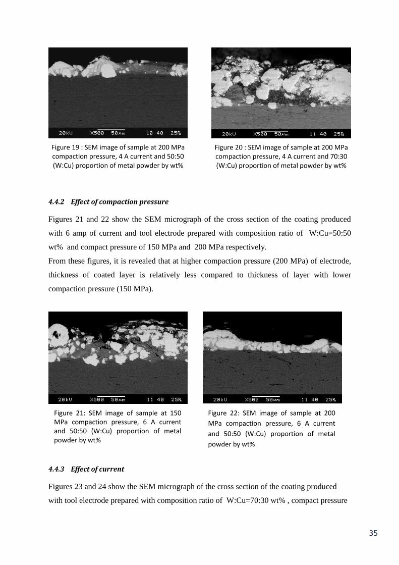
35
Figure 19 : SEM image of sample at 200 MPa compaction pressure, 4 A current and 50:50 (W:Cu) proportion of metal powder by wt%
Figure 20 : SEM image of sample at 200 MPa compaction pressure, 4 A current and 70:30 (W:Cu) proportion of metal powder by wt%
4.4.2 Effect of compaction pressure
Figures 21 and 22 show the SEM micrograph of the cross section of the coating produced
with 6 amp of current and tool electrode prepared with composition ratio of W:Cu=50:50
wt% and compact pressure of 150 MPa and 200 MPa respectively.
From these figures, it is revealed that at higher compaction pressure (200 MPa) of electrode,
thickness of coated layer is relatively less compared to thickness of layer with lower
compaction pressure (150 MPa).
4.4.3 Effect of current
Figures 23 and 24 show the SEM micrograph of the cross section of the coating produced
with tool electrode prepared with composition ratio of W:Cu=70:30 wt% , compact pressure
Figure 21: SEM image of sample at 150 MPa compaction pressure, 6 A current and 50:50 (W:Cu) proportion of metal powder by wt%
Figure 22: SEM image of sample at 200
MPa compaction pressure, 6 A current
and 50:50 (W:Cu) proportion of metal
powder by wt%

36
of 200 MPa and applied current of 2 amp and 4 amp respectively.
From the Figures 23 and 24, the effect of current can be seen. It is observed that increase in
current increases the thickness of coated layer. In Figure 23, broken layer of coating is visible
which may be formed during sample preparation. Furthermore with the higher amount of
tungsten in compact tool (as we discussed previously) coarseness of surface layer increases
and this in turn scraped off at the time of sample preparation.
4.5 XRD analysis
X-ray diffraction (XRD) is a non-destructive analytical technique that is usually used to
detect different phases in any material. It determined the detailed information about the
chemical composition and type of molecular bond of crystalline phase. When a focused X-ray
beam interacts with these planes of atoms, part of the beam is transmitted, part is absorbed by
the sample, part is refracted and scattered, and part is diffracted. For the present experiment
X-ray from CuKα (λ=1.5418 A) radiation has been used. From the obtained data diffraction
pattern has been plotted and were analysed with the help of Phillip‟s X‟pert high score
software.
From the XRD analysis the surface composition for different compositions and compaction
pressures has been analysed. Figures 25, 26 and 27 represent the XRD graphs. Their peaks
were analysed and shown on the peaks position itself in graphs.
From the analysis of XRD pattern presence of W, Cu and WC on the coated surface has
been observed. The amount of „WC‟ increases with the amount of W in powder. It is evident
from the XRD graphs that surface of coating has profuse amount of W, WC with some Cu.
Figure 24: SEM image of sample at 200 MPa
compaction pressure, 4 A current and 70:30
(W:Cu) proportion of metal powder by wt%
Figure 23: SEM image of sample at 200 MPa
compaction pressure, 2 A current and 70:30
(W:Cu) proportion of metal powder by wt%

37
20 40 60 80 100
0
50
100
150
200
250
Inte
nsity
2
W: Cu= 50:50 Wt%
Compact pressure= 150 MPa
Peak current= 8 amp
TON=100 µS
Duty factor=50%
wc
wc
Cu
wc
w
Cu
wc
w
w
w
Cu
wc WC
Cu
Figure 25 : XRD graph of sample with 50:50 proportion by wt% of W:Cu, 150 MPa and 8 A current
20 40 60 80 100
0
50
100
150
W: Cu= 70:30 Wt%
Compact pressure= 150 MPa
Peak current= 8 amp
TON=100 µS
Duty factor=50%
Inte
nsity
2
Cu
Cu
WC
W
WC WC
W
Cu
WC
W
Cu
W
WC
W
Figure 26 : XRD graph of sample with 70:30 proportion by wt% of W:Cu, 150 MPa and 8 A current

38
Figure 27 : XRD graph of sample with 50:50 proportion by wt% of W:Cu, 200 MPa and 8 A current
4.6 Microhardness
Micro-hardness of the coating surfaces were measured by Vickers‟ hardness tester (LECO
Microhardness Tester (LM248AT)). The hardness was checked at 50 gf with 10 seconds of
dwell time.
Due to presence of pores on the coated surface micro hardness value for all the samples
could not be measured. Here in Table 8, micro hardness values of some specific samples are
shown.
Table 8 : Readings of hardness’ and average hardness
Exp. No. 1
(HV)
2
(HV)
3
(HV)
4
(HV)
5
(HV)
6
(HV)
Average
Hardness
(HV)
3 813.7 879.8 886.9 878.7 959.5 981.8 900.06
4 970.4 1120.9 1232.1 1212.4 1144.1 844.1 1087.33
7 967.8 898.5 983.4 1033.9 962.1 1001.9 974.60
8 1377.3 1365.6 1491.3 1222.2 1379.8 1356.6 1365.46
20 40 60 80 100
0
50
100
150
200
250
300
350
W: Cu= 50:50 Wt%
Compact pressure= 200 MPa
Peak current= 8 amp
TON=100 µS
Duty factor=50%
Inte
nsity
2
WC
WC
W
Cu
Cu
WC
W
WC WC
W
Cu
WC
W
Cu
WC
WC

39
From the above values, it can be observed that with increase in current (Experiments 3 & 4
i.e. 50:50 composition and at 150 MPa compaction pressure) when other parameters are
fixed, deposition rate increases and with that average micro hardness also increases.
Further from Exp-7 to Exp-8 (Experiments of 50:50 composition and at 200 MPa
compaction pressure) when current increases from 6 ampere to 8 ampere for tool compact
prepared with 200 MPa compaction pressure average micro hardness value increases. It may
be due to the fact that at higher compaction pressures surface layer created is of great strength
and hardness increases rapidly.
40
Chapter 5
Conclusions
From the current experiments it has been found that WC-Cu composite coating successfully
deposited on AISI 1020 steel substrate.
It has been found that, during electro-discharge processing in a liquid dielectric medium, the
metal transfer from the tool electrode to the work surface can be enhanced using powder
compact tools with reverse polarity.
The green compact tool electrode with lower compaction pressures gives higher amount of
coating over the surface.
With increase of tungsten percentage in the tool electrode, deposition rate increases when
other parameters are kept constant.
EDC method gives improvement in hardness up to 3 to 4 times (i.e. 900- 1365 HV0.05)
compared to substrate material.
Applied current during EDC process is a significant parameter for good compilation of the
ceramic layer on the work- piece surface. Deposition rate of the coating material on substrate
increases with the increase of peak current. However quality of surface becomes poor.
Future scope of project work
Further work could be carried out to study the frictional and wear behavior of the surfaces
obtained by electro-discharge coating process.
It is possible to alter the metallurgical and physicochemical nature of the surface by a
suitable change in the ingredients and compositions of the powder compact.
Optimization of the process parameters can be done by using suitable statistical tool for
maximum deposition rate, less porosity, and harder surface layer with good surface
characteristics of the coated surface. Taguchi, TOPSIS, or other factorial design of
experiments methods can be adopted for optimization of the present experimentation.
41
Chapter 6
References
[1] K. Furutani, A. Saneto, H. Takezava, N. Mohri, and H. Miyake, "Surface modification by electrical
discharge machining with titanium suspended in working fluid," Toyota Technological Institute,
Nagoya, Japan,.
[2] Z.L. Wang, Y. Fang, P.N. Wu, W.S. Zhao, and K. Cheng, "Surface modification process by
electrical discharge machining with a Ti powder green comapct electrode," Journal of Materials
Processing Technology, vol. 129, pp. 139-142, 2002.
[3] P. Janmanee and A. Muttamara, "Surface modification of tungsten carbide by electrical (EDC)
using a titanium powder suspension," Applied Surface Science, vol. 258, pp. 7255-7265, 2012.
[4] A. Gangadhar, M.S. Shunmugan, and P.K. Philip, "Surface modification in electrodischarge
processing with a powder compact tool electrode," Wear, vol. 143, pp. 45-55, 1991.
[5] M.S. Shunmugan, P.K. Philip, and A. Gangadhar, "Improvement of wear resistance by EDM with
tungsten carbide P/M electrode," Wear, vol. 171, pp. 1-5, 1994.
[6] M.P. Samuel and P.K. Philip, "POWER METALLURGY TOOL ELECTRODES FOR ELECTRICAL
DISCHARGE MACHINING ," Int. J. Mach. Tools Manufact. , vol. 37, pp. 1625-1633, 1997.
[7] A. V. Ribalko and O. Sahin, "The use of bipolar current pulses in electrospark alloying of metal
surfaces," Surface and Coatings Technology , vol. 168, pp. 129-135.
[8] J. Simao, D. Aspinwall, F. El-Menshawy, and K. Meadows, "Surface alloying using PM composite
electrode materials when electrical discharge texturing hardened AISI D2," Journal of Materials
Processing Technology, vol. 127, pp. 211-216, 2002.
[9] J. Simao, H.G. Lee, D.K. Aspinwall, R.C. Dewes, and E.M. Aspinwall, "Workpiece surface
modification using electrical discharge machining," International Journal of Machine Tools &

42
Manufacture, vol. 43, pp. 121-128, 2003.
[10] H.G. Lee, J. Simao, D.K. Aspinwall, R.C. Dewes, and W. Voice, "Electrical discharge surface
alloying," Journal of Materials Processing Technology, vol. 149, pp. 334-340, 2004.
[11] T. Moro, N. Mohri, O. Hisashi, A. Goro, and N. Saito, "Study on the surface modification system
with electrical discharge machine in the practical usage," Journal of Materials Processing
Technology, vol. 149, pp. 65-70, 2004.
[12] P.K. Patowari, P. Saha, and P.K. Mishra, "Artificial neural network model in surface modification
by EDM using tungsten–copper powder metallurgy sintered electrodes," Int J Adv Manuf
Technol, vol. 51, no. DOI 10.1007/s00170-010-2653-z, pp. 627-638, 2010.
[13] S. Kumar and U. Batra, "Surface modification of die steel materials by EDM method using
tungsten powder-mixed dielectric," Journal of Manufacturing Processes, vol. 14, pp. 35-40,
2012.
[14] Y. Hwang, C. Kuo, and S Hwang, "The coating of TiC layer on the surface of nickel by electric
discharge coating (EDC) with a multi-layer electrode," Journal of Materials Processing
Technology, vol. 210, pp. 642–652, 2010.
[15] D.K. Aspinwall, R.C. Dewes, H.G. Lee, and J. Simao, "Electrical Discharge Surface Alloying of Ti
and Fe Workpiece Materials Using Refractory Powder Compact Electrodes and Cu Wire".