
Surface Check Report Guidelines v1.0 Surf… · implementation of MicroStation V8i and InRoads V8i....
88
Georgia Department of Transportation Engineering Software Standards & Support InRoads Surface Check Report Guidelines Developed By Engineering Software Standards & Support Product Version InRoads Suite V8i Edition Document Revision Version _1.0 Release Date 07‐01‐10
Transcript of Surface Check Report Guidelines v1.0 Surf… · implementation of MicroStation V8i and InRoads V8i....

Georgia Department of Transportation
Engineering Software Standards & Support
InRoads Surface Check Report
Guidelines
Developed By Engineering Software Standards & SupportProduct Version InRoads Suite V8i Edition Document Revision Version _1.0Release Date 07‐01‐10
ii
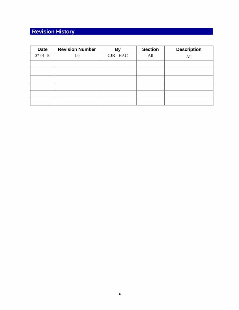
Revision History
Date Revision Number By Section Description 07-01-10 1.0 CJB - HAC All All

iii
This Page Left Intentionally Blank

iv
Preface The InRoads Surface Check Guidelines have been developed as part of the statewide GDOT implementation of MicroStation V8i and InRoads V8i. The intent of this document is to provide guidelines and standards for utilizing InRoads and the associated InRoads “GDOT Surface Check Report” style sheet for verifying the accuracy of the Existing DTM database as compared to the associated Field Survey Data. These guidelines must be followed in detail in order to conform to the current GDOT standards for producing the required tolerance and computation reports for Digital Terrain Model verification. Updates to this document will be made periodically when minor revisions, additional information, and/or enhancements are added. NOTE: The InRoads “GDOT Surface Check Report” style sheet uses specific SMI Codes and Feature Style naming conventions (160 – TOPO_E_MPCKGRD) and (161 – TOPO_E_MPCKPAV) which are discussed in more detail in these guidelines. If there is any deviation from the feature code/feature style conventions as prescribed by this document, the “GDOT Surface Check Report” style sheet will not produce the requisite report. All electronic GDOT Surface Check Report documentation (.HTML file format) shall be provided with the Project deliverables.

v
Contact Information To submit any comments or questions regarding the information contained in this document, please contact the Engineering Software Standards and Support by email at the following address: [email protected] In the Email Subject Header, please reference the InRoads Surface Check Report Guidelines

vi
This Page Left Intentionally Blank
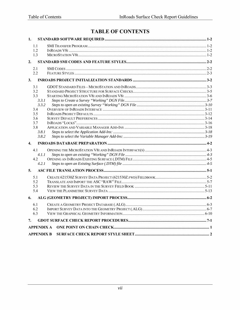
Table of Contents InRoads Surface Check Report Guidelines
vii
TABLE OF CONTENTS 1. STANDARD SOFTWARE REQUIRED ............................................................................................................ 1-2
1.1 SMI TRANSFER PROGRAM .............................................................................................................................. 1-2 1.2 INROADS V8I .................................................................................................................................................. 1-2 1.3 MICROSTATION V8I ........................................................................................................................................ 1-2
2. STANDARD SMI CODES AND FEATURE STYLES ..................................................................................... 2-2
2.1 SMI CODES ..................................................................................................................................................... 2-2 2.2 FEATURE STYLES ............................................................................................................................................ 2-3
3. INROADS PROJECT INITIALIZATION STANDARDS .............................................................................. 3-2
3.1 GDOT STANDARD FILES – MICROSTATION AND INROADS ........................................................................... 3-3 3.2 STANDARD PROJECT STRUCTURE FOR SURFACE CHECKS.............................................................................. 3-5 3.3 STARTING MICROSTATION V8I AND INROADS V8I ....................................................................................... 3-6
3.3.1 Steps to Create a Survey “Working” DGN File ....................................................................................... 3-7 3.3.2 Steps to open an existing Survey “Working” DGN File ........................................................................ 3-10
3.4 OVERVIEW OF INROADS INTERFACE ............................................................................................................ 3-11 3.5 INROADS PROJECT DEFAULTS ...................................................................................................................... 3-12 3.6 SURVEY DEFAULT PREFERENCES ................................................................................................................. 3-14 3.7 INROADS “LOCKS” ........................................................................................................................................ 3-16 3.8 APPLICATION AND VARIABLE MANAGER ADD-INS ..................................................................................... 3-18
3.8.1 Steps to select the Application Add-Ins: ................................................................................................. 3-18 3.8.2 Steps to select the Variable Manager Add-Ins: ...................................................................................... 3-19
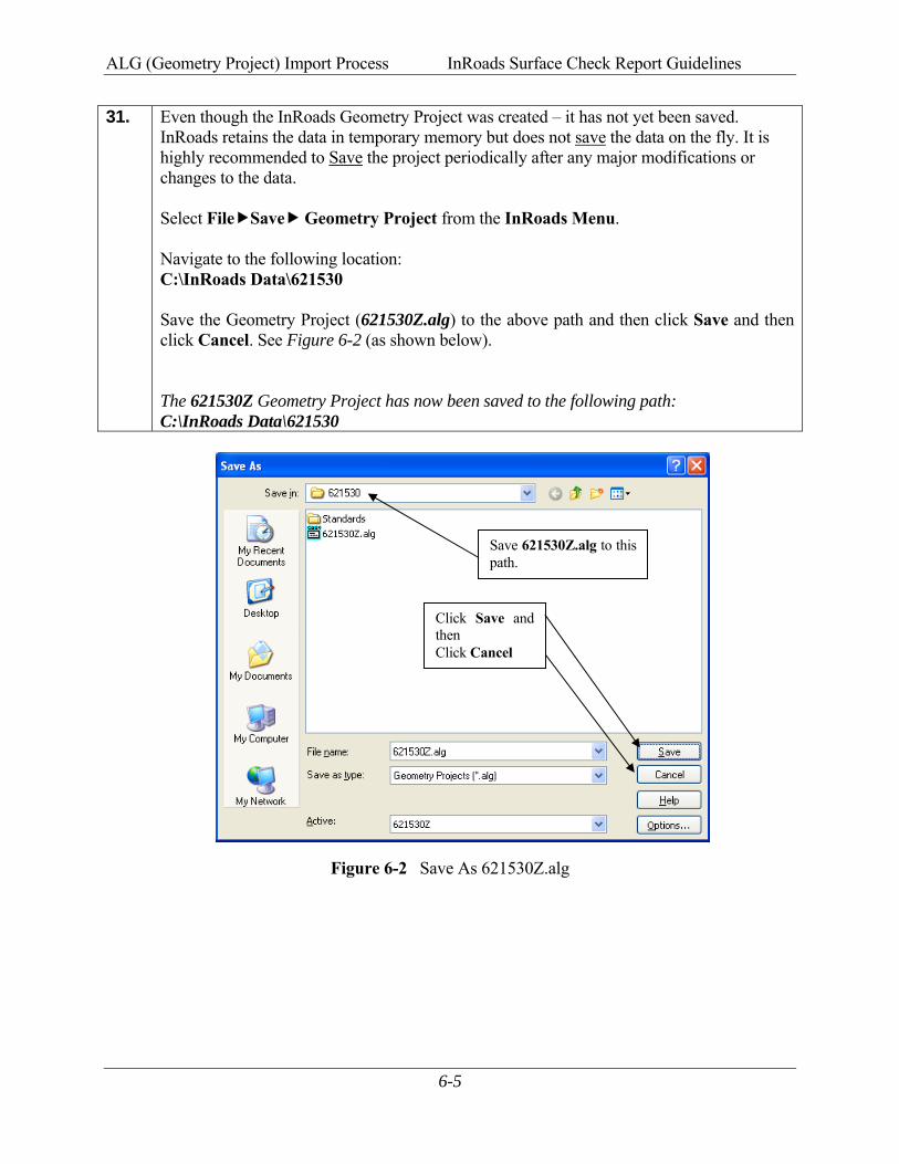
4. INROADS DATABASE PREPARATION ......................................................................................................... 4-2
4.1 OPENING THE MICROSTATION V8I AND INROADS INTERFACE(S) ................................................................. 4-3 4.1.1 Steps to open an existing “Working” DGN File ...................................................................................... 4-3
4.2 OPENING AN INROADS EXISTING SURFACE (.DTM) FILE .............................................................................. 4-5 4.2.1 Steps to open an Existing Surface (.DTM) file ......................................................................................... 4-5
5. ASC FILE TRANSLATION PROCESS ............................................................................................................. 5-1
5.1 CREATE 621530Z SURVEY DATA PROJECT (621530Z.FWD) FIELDBOOK ...................................................... 5-2 5.2 TRANSLATE AND IMPORT THE ASC “RAW” FILE .......................................................................................... 5-7 5.3 REVIEW THE SURVEY DATA IN THE SURVEY FIELD BOOK .......................................................................... 5-11 5.4 VIEW THE PLANIMETRIC SURVEY DATA ...................................................................................................... 5-13
6. ALG (GEOMETRY PROJECT) IMPORT PROCESS .................................................................................... 6-2
6.1 CREATE A GEOMETRY PROJECT DATABASE (.ALG) ...................................................................................... 6-3 6.2 IMPORT SURVEY DATA INTO THE GEOMETRY PROJECT (.ALG) .................................................................... 6-7 6.3 VIEW THE GRAPHICAL GEOMETRY INFORMATION ....................................................................................... 6-10
7. GDOT SURFACE CHECK REPORT PROCEDURES ................................................................................... 7-1
APPENDIX A ONE POINT ON CHAIN CHECK ..................................................................................................... 1
APPENDIX B SURFACE CHECK REPORT STYLE SHEET ............................................................................... 2


Table of Figures InRoads Surface Check Report Guidelines
ix
TABLE OF FIGURES
Figure 3-1 Starting MicroStation V8i and InRoads V8i ................................................................ 3-7 Figure 3-2 MicroStation New File Window ................................................................................... 3-8 Figure 3-3 Main MicroStation V8i Window .................................................................................. 3-9 Figure 3-4 Main InRoads V8i Window .......................................................................................... 3-9 Figure 3-5 Starting MicroStation V8i and InRoads V8i ..............................................................3-10 Figure 3-6 Project Defaults ...........................................................................................................3-13 Figure 3-7 Survey Default Settings ..............................................................................................3-15 Figure 4-1 Starting MicroStation V8i and InRoads V8i ................................................................ 4-3 Figure 4-2 Main MicroStation V8i Window .................................................................................. 4-4 Figure 4-3 Main InRoads V8i Window .......................................................................................... 4-4 Figure 4-4 Surface Tab – InRoads Explorer (Depicting Triangulated DTM) ............................... 4-6 Figure 5-1 InRoads Interface .......................................................................................................... 5-2 Figure 5-2 “New” Survey Data Project .......................................................................................... 5-3 Figure 5-3 Save As 621530Z.fwd ................................................................................................... 5-4 Figure 5-4 Survey Tab – InRoads Explorer (Before File Importation) ......................................... 5-5 Figure 5-5 Import ASC Translator .................................................................................................. 5-8 Figure 5-6 Survey Tab – InRoads Explorer (After File Importation) ........................................... 5-9 Figure 5-7 Survey Field Book .......................................................................................................5-11 Figure 6-1 “New” Geometry Project .............................................................................................. 6-4 Figure 6-2 Save As 621530Z.alg .................................................................................................... 6-5 Figure 6-3 Survey Data to Geometry .............................................................................................. 6-7 Figure 6-4 Geometry Tab – InRoads Explorer (After File Importation) ....................................... 6-8 Figure 6-5 View Horizontal Annotation .......................................................................................6-12 Figure 6-6 Geometry Selection Filter ...........................................................................................6-13 Figure 6-7 Geometry Selection Filter ...........................................................................................6-14 Figure 6-8 View Horizontal Annotation .......................................................................................6-15 Figure 6-9 MicroStation View of Geometry Cogo Points ...........................................................6-16 Figure 7-1 Geometry Selection Filter ............................................................................................. 7-3 Figure 7-2 Geometry Selection Filter ............................................................................................. 7-4 Figure 7-3 Surface Check Report ................................................................................................... 7-5 Figure 7-4 Geometry Selection Filter ............................................................................................. 7-7 Figure 7-5 Geometry Selection Filter ............................................................................................. 7-8 Figure 7-6 Surface Check Report ................................................................................................... 7-9 Figure 7-7 Bentley InRoads Report Browser ...............................................................................7-10 Figure 7-8 GDOT Surface Check Report .....................................................................................7-10 Figure 7-9 Save As dialog box ......................................................................................................7-11

Table of Tables InRoads Surface Check Report Guidelines
x
TABLE OF TABLES
Table 2.1 ............................................................................................................................................. 2-2 Table 2.2 ............................................................................................................................................. 2-3 Table 2.3 ............................................................................................................................................. 2-3 Table 3.1 ............................................................................................................................................. 3-5 Table 3.2 ............................................................................................................................................. 3-6 Table 3.3 ...........................................................................................................................................3-12 Table 3.4 ...........................................................................................................................................3-16 Table 3.5 ...........................................................................................................................................3-17

1-1
Overview These Guidelines cover the GDOT standards for verifying the tolerance and accuracy of an Existing Digital Terrain Model (original terrain surface) as compared against associated field survey points by utilizing the MicroStation V8i and InRoads V8i Software(s). The guidelines also describe and list the required software needed, the standard SMI codes and Feature Codes/Styles for field survey collection, the Project Initialization Standards, the ASC Translation Process and the “GDOT Surface Check Report” generation procedures. Document Content Below is a list of topics covered in this document:
• Standard Software Required • Standard SMI Codes and Feature Styles • InRoads Project Initialization Standards • InRoads Database Preparation • ASC File Translation Process • ALG (Geometry Project) Import Process • GDOT Surface Check Report Procedures • Appendix A • Appendix B

1Standard Software Required

Standard Software Required InRoads Surface Check Report Guidelines
1-2
1. Standard Software Required
The GDOT Surface Check Report is a Style Sheet generated from InRoads which reports the tolerance and accuracy of the Existing Digital Terrain Model surface when compared with field survey check points. This Style Sheet Generation process requires several stand-alone programs which are used in combination to automate the procedure of verifying the accuracy of original terrain data obtained from the Existing Digital Terrain Model surface. This section covers the following Software(s): ● SMI Transfer Program ● InRoads V8i ● MicroStation V8i
1.1 SMI Transfer Program Project Field Survey Data, which is stored in the Data Collector during the setting of the Horizontal and Vertical controls, will be downloaded to a computer using the SMI Transfer Program (Surveyors Module International Transfer Program). The downloaded file will be in an .ASC format (ASCII file format).
1.2 InRoads V8i InRoads V8i is the GDOT Civil Design Software. This program contains the Existing Digital Terrain Model - DTM (original terrain surface) which is to be verified by using the GDOT Surface Check Report Style Sheet in order to determine the accuracy of the DTM point data. This program must be open and operating for the GDOT Surface Check Report Style Sheet to function.
1.3 MicroStation V8i MicroStation V8i is the GDOT CADD Software utilized in conjunction with InRoads to provide temporary or permanent graphics in the CADD environment. This program must be open and operating for the GDOT Surface Check Report Style Sheet to function.

2Standard SMI Codes and Feature Styles
Standard SMI Codes and Feature Styles InRoads Surface Check Report Guidelines
2-2
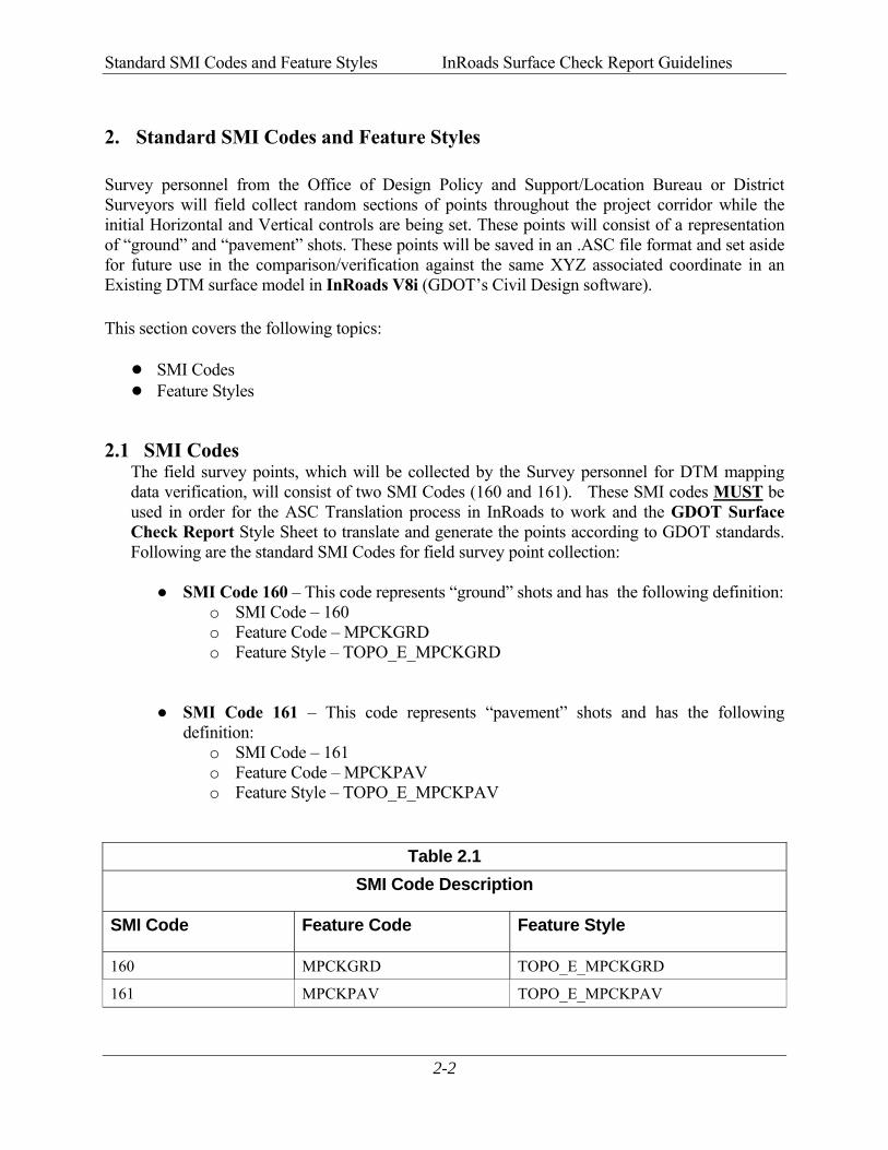
2. Standard SMI Codes and Feature Styles
Survey personnel from the Office of Design Policy and Support/Location Bureau or District Surveyors will field collect random sections of points throughout the project corridor while the initial Horizontal and Vertical controls are being set. These points will consist of a representation of “ground” and “pavement” shots. These points will be saved in an .ASC file format and set aside for future use in the comparison/verification against the same XYZ associated coordinate in an Existing DTM surface model in InRoads V8i (GDOT’s Civil Design software). This section covers the following topics: ● SMI Codes ● Feature Styles
2.1 SMI Codes The field survey points, which will be collected by the Survey personnel for DTM mapping data verification, will consist of two SMI Codes (160 and 161). These SMI codes MUST be used in order for the ASC Translation process in InRoads to work and the GDOT Surface Check Report Style Sheet to translate and generate the points according to GDOT standards. Following are the standard SMI Codes for field survey point collection:
● SMI Code 160 – This code represents “ground” shots and has the following definition: o SMI Code – 160 o Feature Code – MPCKGRD o Feature Style – TOPO_E_MPCKGRD
● SMI Code 161 – This code represents “pavement” shots and has the following definition:
o SMI Code – 161 o Feature Code – MPCKPAV o Feature Style – TOPO_E_MPCKPAV
Table 2.1 SMI Code Description
SMI Code Feature Code Feature Style
160 MPCKGRD TOPO_E_MPCKGRD
161 MPCKPAV TOPO_E_MPCKPAV
Standard SMI Codes and Feature Styles InRoads Surface Check Report Guidelines
2-3
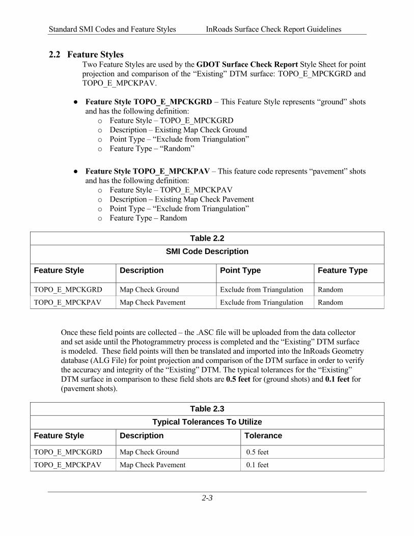
2.2 Feature Styles Two Feature Styles are used by the GDOT Surface Check Report Style Sheet for point projection and comparison of the “Existing” DTM surface: TOPO_E_MPCKGRD and TOPO_E_MPCKPAV.
● Feature Style TOPO_E_MPCKGRD – This Feature Style represents “ground” shots
and has the following definition: o Feature Style – TOPO_E_MPCKGRD o Description – Existing Map Check Ground o Point Type – “Exclude from Triangulation” o Feature Type – “Random”
● Feature Style TOPO_E_MPCKPAV – This feature code represents “pavement” shots
and has the following definition: o Feature Style – TOPO_E_MPCKPAV o Description – Existing Map Check Pavement o Point Type – “Exclude from Triangulation” o Feature Type – Random
Table 2.2
SMI Code Description
Feature Style Description Point Type Feature Type
TOPO_E_MPCKGRD Map Check Ground Exclude from Triangulation Random
TOPO_E_MPCKPAV Map Check Pavement Exclude from Triangulation Random Once these field points are collected – the .ASC file will be uploaded from the data collector and set aside until the Photogrammetry process is completed and the “Existing” DTM surface is modeled. These field points will then be translated and imported into the InRoads Geometry database (ALG File) for point projection and comparison of the DTM surface in order to verify the accuracy and integrity of the “Existing” DTM. The typical tolerances for the “Existing” DTM surface in comparison to these field shots are 0.5 feet for (ground shots) and 0.1 feet for (pavement shots).
Table 2.3 Typical Tolerances To Utilize
Feature Style Description Tolerance
TOPO_E_MPCKGRD Map Check Ground 0.5 feet
TOPO_E_MPCKPAV Map Check Pavement 0.1 feet

3InRoads Project Initialization Standards

InRoads Project Initialization Standards InRoads Surface Check Report Guidelines
3-2
3. InRoads Project Initialization Standards Project Initialization Standards have been established in order to promote consistency and assist in the organization of project data for use in the GDOT Surface Check Report Style Sheet. These standard project schemes help to ensure uniformity on Surface Check projects. This section covers the following topics: ● GDOT Standard Files (MicroStation and InRoads) ● Standard Project Structure for Surface Checks ● Starting MicroStation V8i and InRoads V8i ● Overview of InRoads Interface ● InRoads Project Defaults ● Survey Default Preferences ● InRoads “Locks” ● Application and Variable Manager Add-Ins

InRoads Project Initialization Standards InRoads Surface Check Report Guidelines
3-3
3.1 GDOT Standard Files – MicroStation and InRoads In order to conform to current policy for deliverables – GDOT provides the requisite files needed to standardize InRoads and MicroStation to GDOT requirements. The first step in the development of an InRoads and MicroStation Project for Surface Checks is to ensure that these standard files are being utilized. Instructions for downloading/installing the executables are included on the GDOT R.O.A.D.S. web page (see the links depicted below). These files are required for any Projects generated for GDOT as well as for use in utilizing the GDOT Surface Check Report Style Sheet. • MicroStation Standard Files Location For Internal GDOT Users – a server location has
been established to map a drive (an N:\ Drive) in order to access the latest MicroStation Files. Once the internal user maps this N:\ drive to the following location – all of the standard MicroStation Files will be available through this mapped drive: TO BE DEVELOPED
• MicroStation Standard Files Location For External Users - a MicroStation V8i (CaddALLV8i.exe) executable file is available and located in a download executable which can be accessed from the GDOT R.O.A.D.S. web page. This executable contains all of the GDOT MicroStation V8i standard files. This file can be downloaded from the following location:
TO BE DEVELOPED • InRoads Standard Files Location For Internal and External Users - an InRoadsALL executable file (InRoadsALLV8i.exe) is available and located in a download executable which can be accessed from the GDOT R.O.A.D.S. web page. This executable contains all of the GDOT InRoads V8i standard files. This file can be downloaded from the following location:
TO BE DEVELOPED

InRoads Project Initialization Standards InRoads Surface Check Report Guidelines
3-4
The InRoadsALLV8i.exe file contains all of the standard GDOT files which are required to generate projects to GDOT standards. The user will perform the following steps to extract and set-up the GDOT Standard InRoads Files:
1. Close MicroStation V8i and InRoads V8i if they are still open.
2. Browse to the following web page: TO BE DEVELOPED
3. Save the InRoadsALLV8i.exe file to the hard drive and then double click the file.
4. The self-extractor will download the GDOT InRoads Standard Files to the following locations:
a. C:\InRoads Data\Standards\ GDOT 3D Working File.dgn GDOT_Standard V8i.xin GDOT_Standard V8i.itl Project_Data_Sheet_MultipleAlign.docm Photogrammetry_InRoads QA.docx Survey Data Processing_InRoads QA.docx Design Data_ InRoads QA.docx
b. C:\InRoads Data\Component Documentation
GDOT Component Description Help Documentation
c. C:\InRoads Data\Style Sheet Documentation GDOT Style Sheet Help Documentation
d. C:\Program Files\Bentley\InRoads Group V8.11\XML Data\GDOT\
GDOT Style Sheets
5. For detailed instructions on downloading and installing InRoadsALLV8i.exe - please go to the following link TO BE DEVELOPED and click on the Downloading and Running InRoadsALLV8i.pdf document for installing these standard files.
InRoads Project Initialization Standards InRoads Surface Check Report Guidelines
3-5
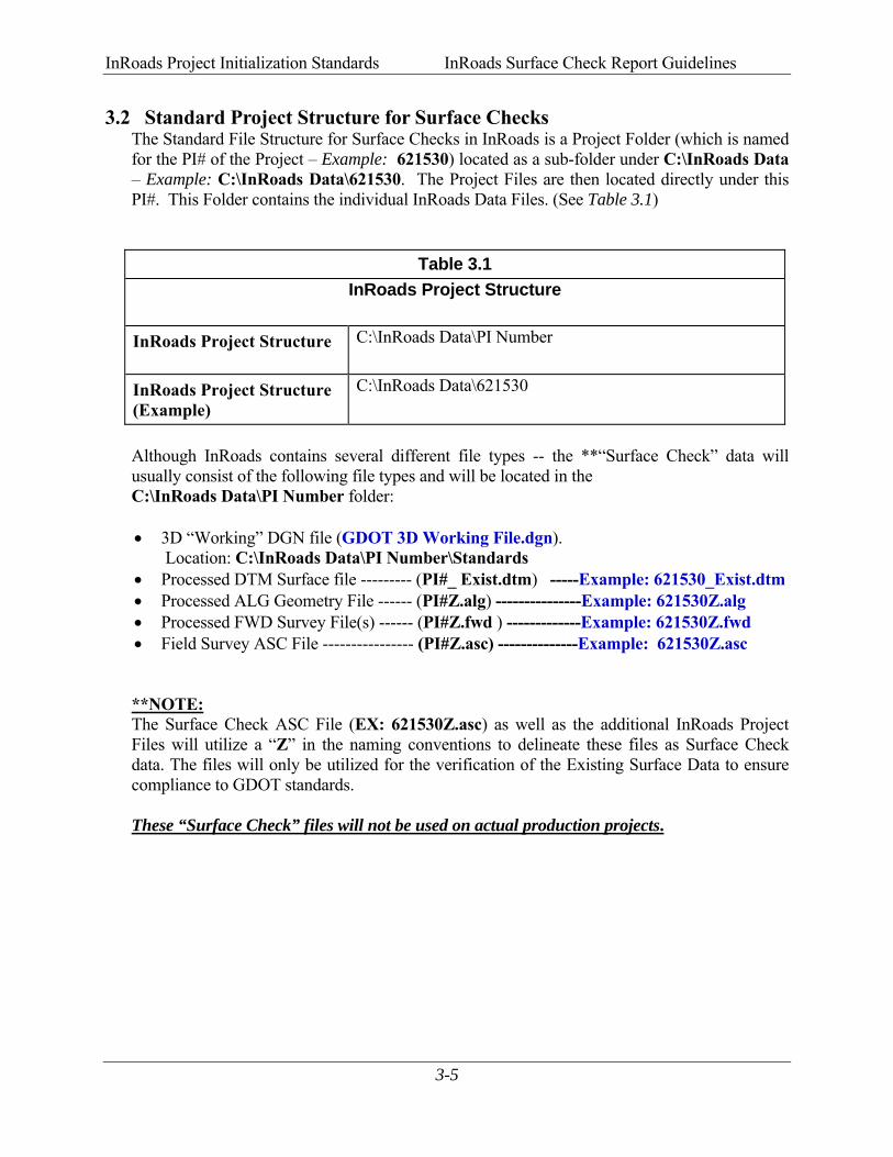
3.2 Standard Project Structure for Surface Checks The Standard File Structure for Surface Checks in InRoads is a Project Folder (which is named for the PI# of the Project – Example: 621530) located as a sub-folder under C:\InRoads Data – Example: C:\InRoads Data\621530. The Project Files are then located directly under this PI#. This Folder contains the individual InRoads Data Files. (See Table 3.1)
Table 3.1 InRoads Project Structure
InRoads Project Structure C:\InRoads Data\PI Number
InRoads Project Structure (Example)
C:\InRoads Data\621530
Although InRoads contains several different file types -- the **“Surface Check” data will usually consist of the following file types and will be located in the C:\InRoads Data\PI Number folder: • 3D “Working” DGN file (GDOT 3D Working File.dgn).
Location: C:\InRoads Data\PI Number\Standards • Processed DTM Surface file --------- (PI#_ Exist.dtm) -----Example: 621530_Exist.dtm • Processed ALG Geometry File ------ (PI#Z.alg) ---------------Example: 621530Z.alg • Processed FWD Survey File(s) ------ (PI#Z.fwd ) -------------Example: 621530Z.fwd • Field Survey ASC File ---------------- (PI#Z.asc) --------------Example: 621530Z.asc
**NOTE: The Surface Check ASC File (EX: 621530Z.asc) as well as the additional InRoads Project Files will utilize a “Z” in the naming conventions to delineate these files as Surface Check data. The files will only be utilized for the verification of the Existing Surface Data to ensure compliance to GDOT standards. These “Surface Check” files will not be used on actual production projects.

InRoads Project Initialization Standards InRoads Surface Check Report Guidelines
3-6
3.3 Starting MicroStation V8i and InRoads V8i The user will be working in both MicroStation V8i (the CADD Software) and InRoads Suite V8i (the Survey/Design Software). The MicroStation CADD Software is used for the viewing and manipulation of graphics derived from InRoads. The InRoads Software is the database in which the Surveying data for the Surface Check is created and processed. The user will select the standard GDOT 3D “seed” file to use as the “seed” DGN in order to create the three dimensional “Working” DGN file. This “Working” DGN file is used to display the temporary and/or permanent graphics in InRoads.
This section details the following processes:
● Steps to Create a Survey “Working” DGN File ● Steps to Open an Existing Survey “Working” DGN File
The “Working” DGN file will be saved to the following folder location: C:\InRoads Data\PI Number\Standards
(IF the Standards folder – does not yet exist – the user will need to create the folder).
Table 3.2 Standard Naming Convention of the “Working” DGN File
Working DGN File Name C:\InRoads Data\PI Number\Standards
GDOT 3D Working File.dgn
The MicroStation software will open first before InRoads. After the MicroStation Splash Screen appears, the MicroStation Manager dialog (See Figure 3-1) will open so that a “Working” DGN file can be created or an existing “Working” DGN file can be opened. The InRoads software can then be initiated.
InRoads Project Initialization Standards InRoads Surface Check Report Guidelines
3-7
3.3.1 Steps to Create a Survey “Working” DGN File The Survey “Working” DGN file will be created from the GDOT_V8_3D.dgn seed file.
Following are the steps to create a Survey “Working” DGN File:
1. From the desktop, double-click on the GDOT MicroStation V8i Edition icon.
2. After the MicroStation Splash Screen appears, the MicroStation Manager dialog box will open. (See Figure 3-1).
Figure 3-1 Starting MicroStation V8i and InRoads V8i
3. In the MicroStation Manager dialog box, click on the New File icon (See Figure 3-1) depicted above. The New File command will be used to create the “Working” DGN file.
Double click on the icon labeled GDOT MicroStation V8i Edition.
New File Icon
InRoads Project Initialization Standards InRoads Surface Check Report Guidelines
3-8
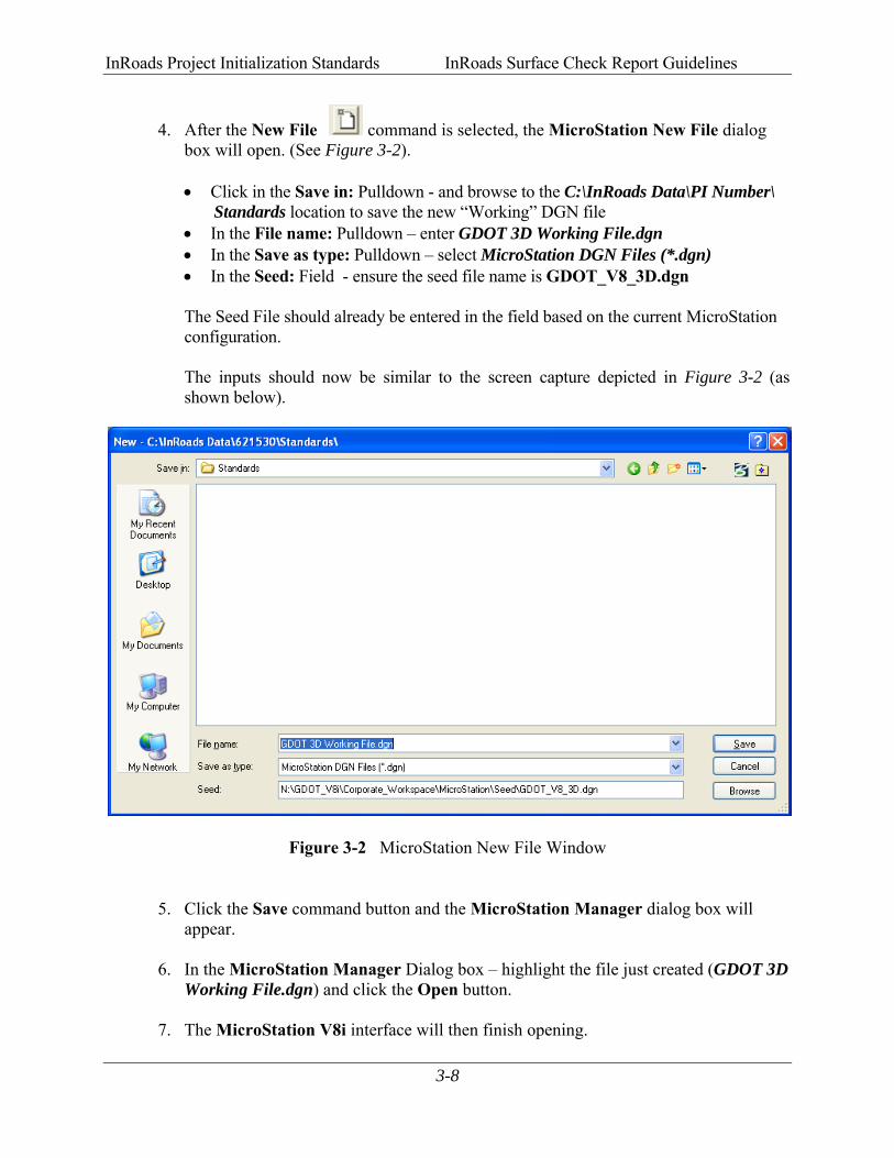
4. After the New File command is selected, the MicroStation New File dialog box will open. (See Figure 3-2).
• Click in the Save in: Pulldown - and browse to the C:\InRoads Data\PI Number\ Standards location to save the new “Working” DGN file • In the File name: Pulldown – enter GDOT 3D Working File.dgn • In the Save as type: Pulldown – select MicroStation DGN Files (*.dgn) • In the Seed: Field - ensure the seed file name is GDOT_V8_3D.dgn The Seed File should already be entered in the field based on the current MicroStation configuration.
The inputs should now be similar to the screen capture depicted in Figure 3-2 (as shown below).
Figure 3-2 MicroStation New File Window
5. Click the Save command button and the MicroStation Manager dialog box will appear.
6. In the MicroStation Manager Dialog box – highlight the file just created (GDOT 3D
Working File.dgn) and click the Open button. 7. The MicroStation V8i interface will then finish opening.
InRoads Project Initialization Standards InRoads Surface Check Report Guidelines
3-9
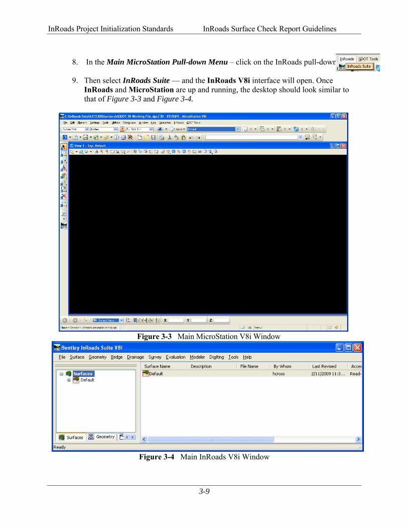
8. In the Main MicroStation Pull-down Menu – click on the InRoads pull-down: 9. Then select InRoads Suite — and the InRoads V8i interface will open. Once
InRoads and MicroStation are up and running, the desktop should look similar to that of Figure 3-3 and Figure 3-4.
Figure 3-3 Main MicroStation V8i Window
Figure 3-4 Main InRoads V8i Window
InRoads Project Initialization Standards InRoads Surface Check Report Guidelines
3-10
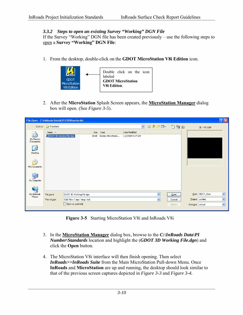
3.3.2 Steps to open an existing Survey “Working” DGN File If the Survey “Working” DGN file has been created previously – use the following steps to
open a Survey “Working” DGN File:
1. From the desktop, double-click on the GDOT MicroStation V8i Edition icon.
2. After the MicroStation Splash Screen appears, the MicroStation Manager dialog
box will open. (See Figure 3-5).
Figure 3-5 Starting MicroStation V8i and InRoads V8i
3. In the MicroStation Manager dialog box, browse to the C:\InRoads Data\PI Number\Standards location and highlight the (GDOT 3D Working File.dgn) and click the Open button.
4. The MicroStation V8i interface will then finish opening. Then select InRoads>>InRoads Suite from the Main MicroStation Pull-down Menu. Once InRoads and MicroStation are up and running, the desktop should look similar to that of the previous screen captures depicted in Figure 3-3 and Figure 3-4.
Double click on the icon labeled GDOT MicroStation V8i Edition.
InRoads Project Initialization Standards InRoads Surface Check Report Guidelines
3-11
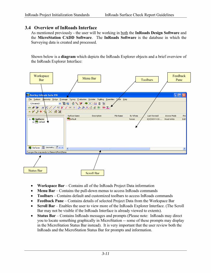
3.4 Overview of InRoads Interface As mentioned previously - the user will be working in both the InRoads Design Software and the MicroStation CADD Software. The InRoads Software is the database in which the Surveying data is created and processed.
Shown below is a diagram which depicts the InRoads Explorer objects and a brief overview of the InRoads Explorer Interface:
• Workspace Bar – Contains all of the InRoads Project Data information • Menu Bar – Contains the pull-down menus to access InRoads commands • Toolbars – Contains default and customized toolbars to access InRoads commands • Feedback Pane – Contains details of selected Project Data from the Workspace Bar • Scroll Bar – Enables the user to view more of the InRoads Explorer Interface. (The Scroll
Bar may not be visible if the InRoads Interface is already viewed to extents). • Status Bar – Contains InRoads messages and prompts (Please note: InRoads may direct
you to locate something graphically in MicroStation -- some of these prompts may display in the MicroStation Status Bar instead). It is very important that the user review both the InRoads and the MicroStation Status Bar for prompts and information.
Menu Bar Toolbars
Status BarScroll Bar
Workspace Bar
Feedback Pane

InRoads Project Initialization Standards InRoads Surface Check Report Guidelines
3-12
3.5 InRoads Project Defaults The InRoads Project Defaults setting allows you to define the “default folder locations” for projects (in this case a Surface Check Project). A Project Default configuration can then be saved for each Surface Check project so that multiple projects can be accessed. This configuration allows you to easily navigate between projects. Once the Project Folder locations are saved in the Configuration, the projects can then be accessed by selecting the appropriate Project Configuration Name. The Project Defaults also contain the location for selecting the standard GDOT InRoads Preference File (GDOT_Standard V8i.xin). The standard Project Default Configuration for Surface Check Projects will be PI Number_Z. Each Surface Check Project Default setting will consist of this naming structure in order to easily navigate between projects. (See Table 3.3) **Once the Project Default Location is set for a particular project – this will also be the default folder location whenever the InRoads commands of File Save and File Close are used.
Table 3.3
Project Defaults Configuration
Project Default Structure PI Number_Z
Project Default Structure (Example)
621530_Z
Following are the steps to create a Surface Check Project Default Configuration (Substitute the appropriate PI # as required):
1. Click File Project Defaults from the InRoads pull-down menu to access the Set Project Defaults dialog box.
2. Click New and enter 621530_Z in the New Configuration dialog box. Then click OK.
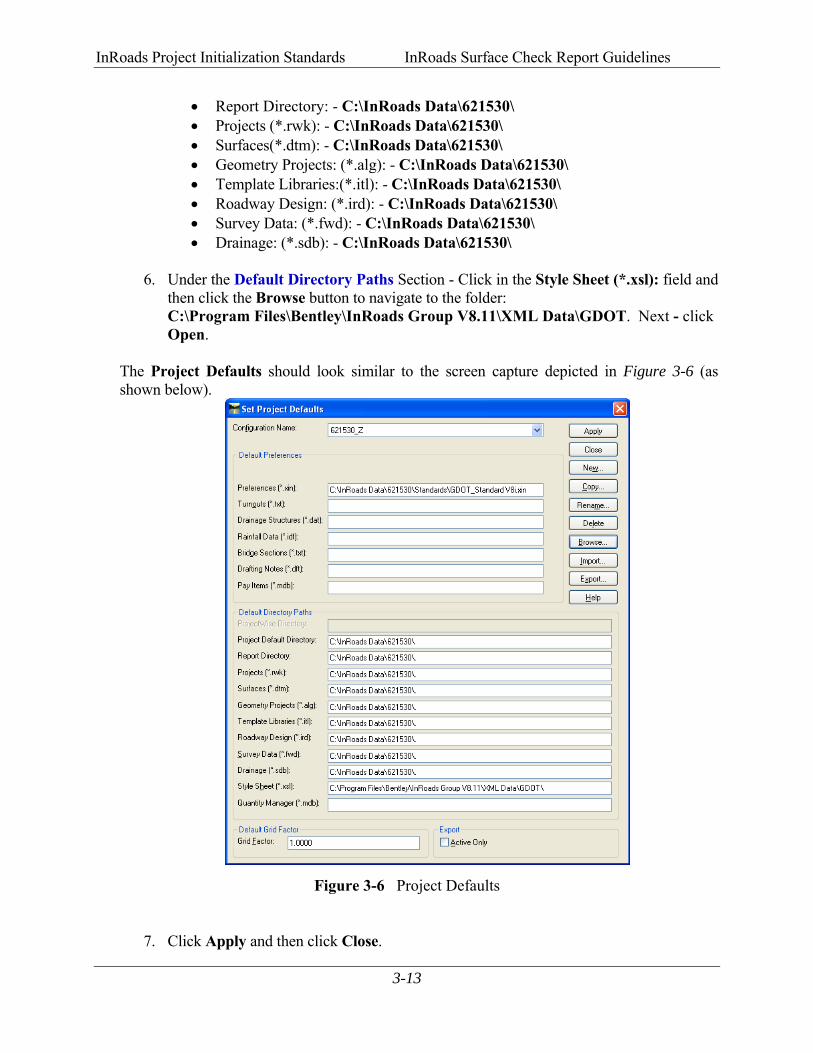
3. Under the Default Preferences section - Click in the Preferences (*.xin): field and then click the Browse button to navigate to the following file: C:\InRoads Data\621530\Standards\GDOT_Standard V8i.xin file and click Open.
4. Under the Default Directory Paths Section - Click in the Project Default Directory: field and then click the Browse button to navigate to the folder: C:\InRoads Data\621530\. Next - click Open.
5. Under the Default Directory Paths Section – copy and paste the following text into each entry field shown below: C:\InRoads Data\621530\
InRoads Project Initialization Standards InRoads Surface Check Report Guidelines
3-13
• Report Directory: - C:\InRoads Data\621530\ • Projects (*.rwk): - C:\InRoads Data\621530\ • Surfaces(*.dtm): - C:\InRoads Data\621530\ • Geometry Projects: (*.alg): - C:\InRoads Data\621530\ • Template Libraries:(*.itl): - C:\InRoads Data\621530\ • Roadway Design: (*.ird): - C:\InRoads Data\621530\ • Survey Data: (*.fwd): - C:\InRoads Data\621530\ • Drainage: (*.sdb): - C:\InRoads Data\621530\
6. Under the Default Directory Paths Section - Click in the Style Sheet (*.xsl): field and
then click the Browse button to navigate to the folder: C:\Program Files\Bentley\InRoads Group V8.11\XML Data\GDOT. Next - click Open.
The Project Defaults should look similar to the screen capture depicted in Figure 3-6 (as shown below).
Figure 3-6 Project Defaults
7. Click Apply and then click Close.
InRoads Project Initialization Standards InRoads Surface Check Report Guidelines
3-14
3.6 Survey Default Preferences The Survey Default Preferences must be loaded in InRoads in order to conform to standards for the processing of Surface Check Projects. This is a very important step to ensure that standards are followed for any Surface Check processes that will be performed. The Survey Default Preference loads the Precision Settings, Tolerances, Units and Formats, Default Point and Alignment Numbering scheme(s), etc. Once the Survey Default Preference is loaded – the project will retain these settings each time the project is accessed. Following are the steps to set the Survey Default Preferences:
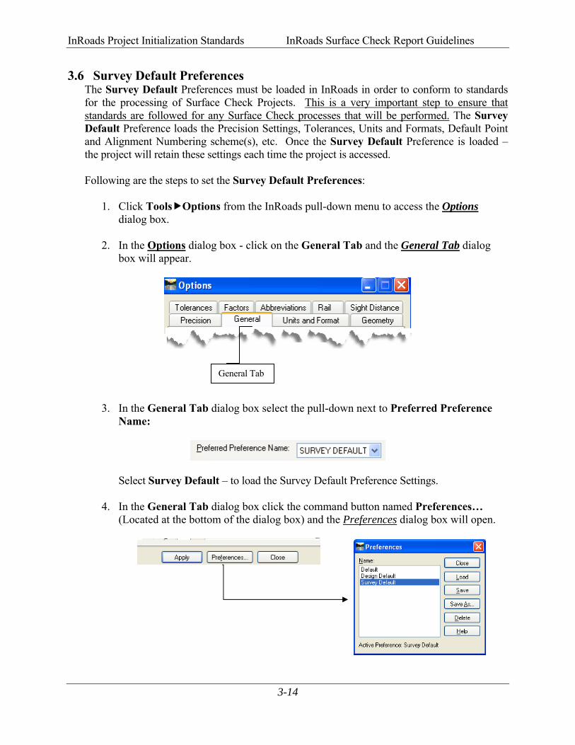
1. Click Tools Options from the InRoads pull-down menu to access the Options dialog box.
2. In the Options dialog box - click on the General Tab and the General Tab dialog box will appear.
3. In the General Tab dialog box select the pull-down next to Preferred Preference
Name:
Select Survey Default – to load the Survey Default Preference Settings.
4. In the General Tab dialog box click the command button named Preferences… (Located at the bottom of the dialog box) and the Preferences dialog box will open.
General Tab
InRoads Project Initialization Standards InRoads Surface Check Report Guidelines
3-15
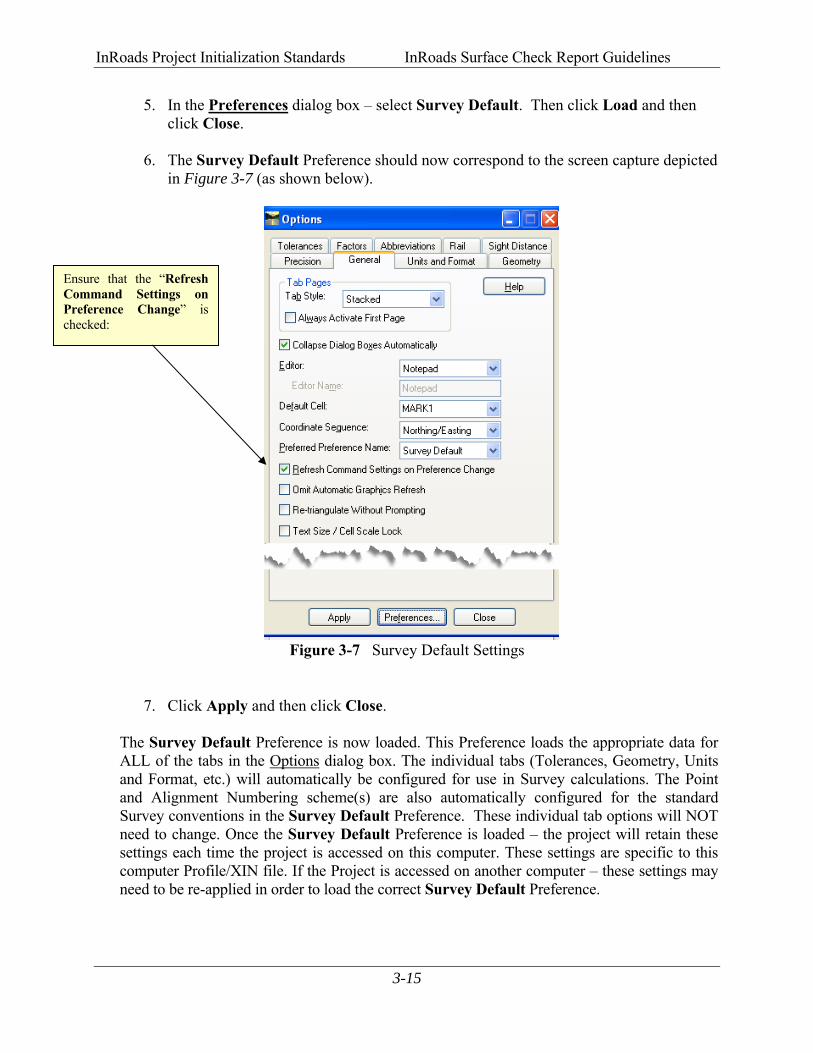
5. In the Preferences dialog box – select Survey Default. Then click Load and then click Close.
6. The Survey Default Preference should now correspond to the screen capture depicted in Figure 3-7 (as shown below).
Figure 3-7 Survey Default Settings
7. Click Apply and then click Close. The Survey Default Preference is now loaded. This Preference loads the appropriate data for ALL of the tabs in the Options dialog box. The individual tabs (Tolerances, Geometry, Units and Format, etc.) will automatically be configured for use in Survey calculations. The Point and Alignment Numbering scheme(s) are also automatically configured for the standard Survey conventions in the Survey Default Preference. These individual tab options will NOT need to change. Once the Survey Default Preference is loaded – the project will retain these settings each time the project is accessed on this computer. These settings are specific to this computer Profile/XIN file. If the Project is accessed on another computer – these settings may need to be re-applied in order to load the correct Survey Default Preference.
Ensure that the “Refresh Command Settings on Preference Change” is checked:
InRoads Project Initialization Standards InRoads Surface Check Report Guidelines
3-16
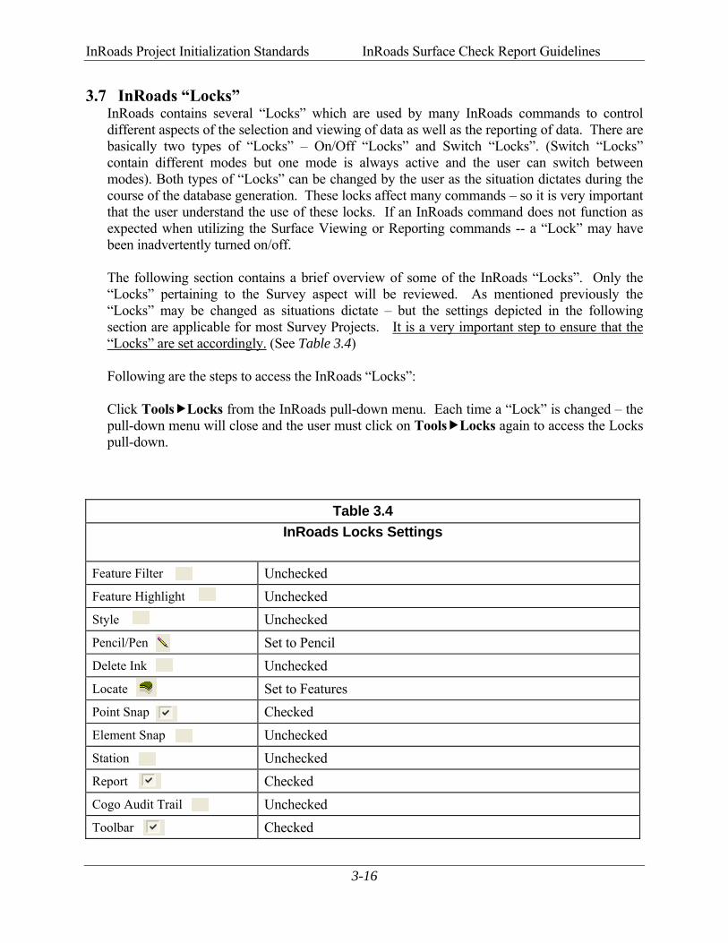
3.7 InRoads “Locks” InRoads contains several “Locks” which are used by many InRoads commands to control different aspects of the selection and viewing of data as well as the reporting of data. There are basically two types of “Locks” – On/Off “Locks” and Switch “Locks”. (Switch “Locks” contain different modes but one mode is always active and the user can switch between modes). Both types of “Locks” can be changed by the user as the situation dictates during the course of the database generation. These locks affect many commands – so it is very important that the user understand the use of these locks. If an InRoads command does not function as expected when utilizing the Surface Viewing or Reporting commands -- a “Lock” may have been inadvertently turned on/off.
The following section contains a brief overview of some of the InRoads “Locks”. Only the “Locks” pertaining to the Survey aspect will be reviewed. As mentioned previously the “Locks” may be changed as situations dictate – but the settings depicted in the following section are applicable for most Survey Projects. It is a very important step to ensure that the “Locks” are set accordingly. (See Table 3.4) Following are the steps to access the InRoads “Locks”: Click Tools Locks from the InRoads pull-down menu. Each time a “Lock” is changed – the pull-down menu will close and the user must click on Tools Locks again to access the Locks pull-down.
Table 3.4 InRoads Locks Settings
Feature Filter Unchecked Feature Highlight Unchecked Style Unchecked Pencil/Pen Set to Pencil Delete Ink Unchecked Locate Set to Features Point Snap Checked Element Snap Unchecked Station Unchecked Report Checked Cogo Audit Trail Unchecked Toolbar Checked

InRoads Project Initialization Standards InRoads Surface Check Report Guidelines
3-17
Following is a brief overview of the InRoads “Locks”: (See Table 3.5)
Table 3.5 InRoads Locks Overview
Feature Filter displays or obscures Surface Features based on a filter (also controls Survey Style Filter) Feature Highlight highlights the feature in plan view when selected from a list Style determines if a dialog box is displayed for a surface command or cross sections Pencil/Pen controls the redisplaying of Graphics Delete Ink allows redisplayed graphics to replace graphics in pen mode Locate controls if Locate Buttons snap to Graphics or Features Point Snap controls the ability to snap to points in Geometry Project Element Snap controls the ability to snap to elements in Geometry Project Station controls the Stationing as it pertains to Cross Sections Report controls if Report is displayed or not displayed in a dialog box Cogo Audit Trail controls the reporting of coordinate geometry results to a text file Toolbar displays or turns off the Locks Toolbar
InRoads Project Initialization Standards InRoads Surface Check Report Guidelines
3-18
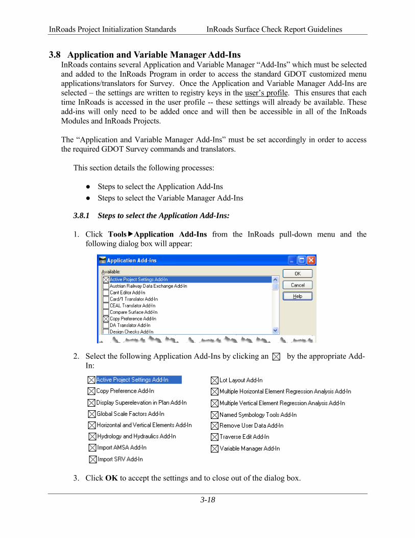
3.8 Application and Variable Manager Add-Ins InRoads contains several Application and Variable Manager “Add-Ins” which must be selected and added to the InRoads Program in order to access the standard GDOT customized menu applications/translators for Survey. Once the Application and Variable Manager Add-Ins are selected – the settings are written to registry keys in the user’s profile. This ensures that each time InRoads is accessed in the user profile -- these settings will already be available. These add-ins will only need to be added once and will then be accessible in all of the InRoads Modules and InRoads Projects.
The “Application and Variable Manager Add-Ins” must be set accordingly in order to access the required GDOT Survey commands and translators.
This section details the following processes:
● Steps to select the Application Add-Ins ● Steps to select the Variable Manager Add-Ins
3.8.1 Steps to select the Application Add-Ins:
1. Click Tools Application Add-Ins from the InRoads pull-down menu and the following dialog box will appear:
2. Select the following Application Add-Ins by clicking an by the appropriate Add-In:
3. Click OK to accept the settings and to close out of the dialog box.
InRoads Project Initialization Standards InRoads Surface Check Report Guidelines
3-19
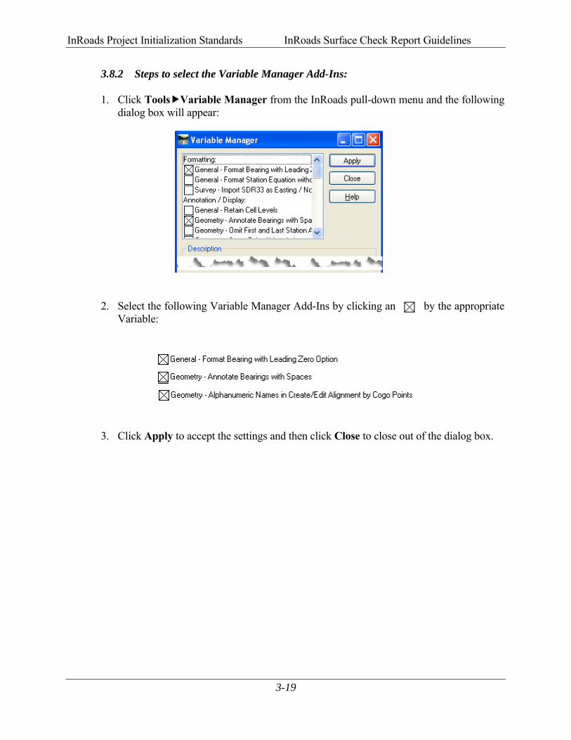
3.8.2 Steps to select the Variable Manager Add-Ins:
1. Click Tools Variable Manager from the InRoads pull-down menu and the following dialog box will appear:
2. Select the following Variable Manager Add-Ins by clicking an by the appropriate Variable:
3. Click Apply to accept the settings and then click Close to close out of the dialog box.

4InRoads Database Preparation

InRoads Database Preparation InRoads Surface Check Report Guidelines
4-2
4. InRoads Database Preparation
This section provides an overview of the necessary steps to ensure that the InRoads project database(s) contain the required information for use in the Surface Check verification procedures. In order for the “GDOT Surface Check Report” Style Sheet to function as intended, the project database MUST contain an Existing DTM Surface. This is the surface model which will be compared to the field survey points (ASC Data) to ensure the accuracy of the DTM original terrain data. The user will receive an Existing Surface file (.DTM). This is the Surface file which is to be verified/checked for accuracy. This .DTM file will be copied into the C:\InRoads Data\PI# Folder (Example C:\InRoads Data\621530). Substitute applicable PI# as required. This DTM will be used as the base surface for the DTM Surface Check. This Section covers the following topics: ● Opening the MicroStation V8i and InRoads Interface(s) ● Opening an InRoads Existing Surface (.DTM) File
InRoads Database Preparation InRoads Surface Check Report Guidelines
4-3
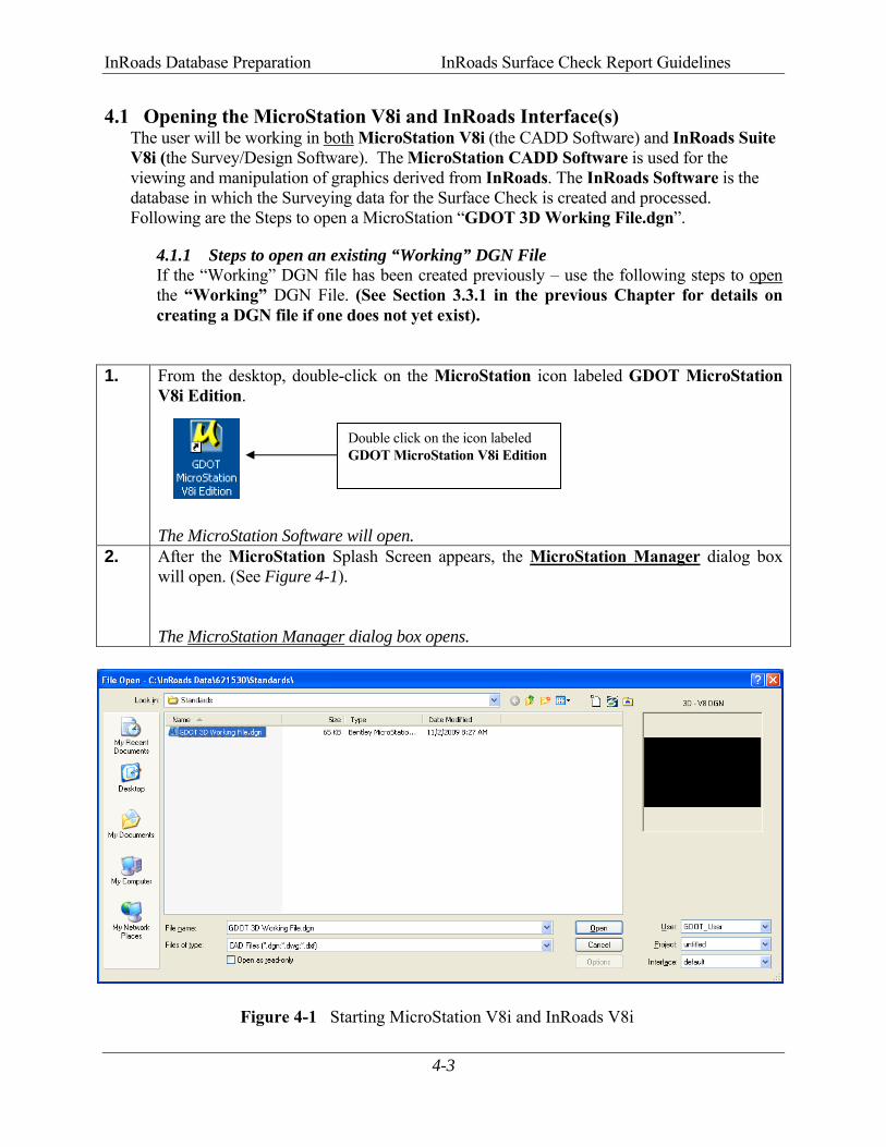
4.1 Opening the MicroStation V8i and InRoads Interface(s) The user will be working in both MicroStation V8i (the CADD Software) and InRoads Suite V8i (the Survey/Design Software). The MicroStation CADD Software is used for the viewing and manipulation of graphics derived from InRoads. The InRoads Software is the database in which the Surveying data for the Surface Check is created and processed. Following are the Steps to open a MicroStation “GDOT 3D Working File.dgn”.
4.1.1 Steps to open an existing “Working” DGN File If the “Working” DGN file has been created previously – use the following steps to open
the “Working” DGN File. (See Section 3.3.1 in the previous Chapter for details on creating a DGN file if one does not yet exist).
1. From the desktop, double-click on the MicroStation icon labeled GDOT MicroStation V8i Edition. The MicroStation Software will open.
2. After the MicroStation Splash Screen appears, the MicroStation Manager dialog box will open. (See Figure 4-1). The MicroStation Manager dialog box opens.
Figure 4-1 Starting MicroStation V8i and InRoads V8i
Double click on the icon labeled GDOT MicroStation V8i Edition
InRoads Database Preparation InRoads Surface Check Report Guidelines
4-4
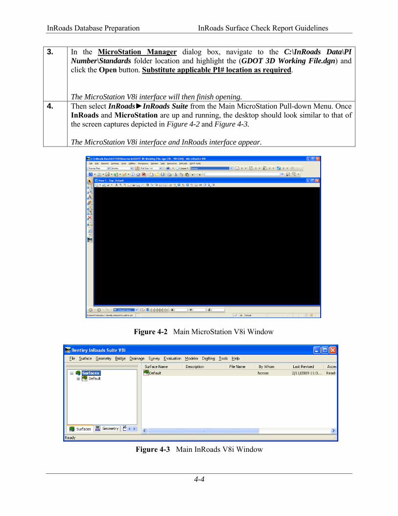
3. In the MicroStation Manager dialog box, navigate to the C:\InRoads Data\PI Number\Standards folder location and highlight the (GDOT 3D Working File.dgn) and click the Open button. Substitute applicable PI# location as required. The MicroStation V8i interface will then finish opening.
4. Then select InRoads►InRoads Suite from the Main MicroStation Pull-down Menu. Once InRoads and MicroStation are up and running, the desktop should look similar to that of the screen captures depicted in Figure 4-2 and Figure 4-3. The MicroStation V8i interface and InRoads interface appear.
Figure 4-2 Main MicroStation V8i Window
Figure 4-3 Main InRoads V8i Window
InRoads Database Preparation InRoads Surface Check Report Guidelines
4-5
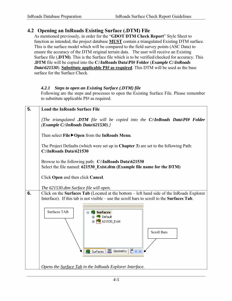
4.2 Opening an InRoads Existing Surface (.DTM) File As mentioned previously, in order for the “GDOT DTM Check Report” Style Sheet to function as intended, the project database MUST contain a triangulated Existing DTM surface. This is the surface model which will be compared to the field survey points (ASC Data) to ensure the accuracy of the DTM original terrain data. The user will receive an Existing Surface file (.DTM). This is the Surface file which is to be verified/checked for accuracy. This .DTM file will be copied into the C:\InRoads Data\PI# Folder (Example C:\InRoads Data\621530). Substitute applicable PI# as required. This DTM will be used as the base surface for the Surface Check.
4.2.1 Steps to open an Existing Surface (.DTM) file Following are the steps and processes to open the Existing Surface File. Please remember
to substitute applicable PI# as required. 5. Load the InRoads Surface File
[The triangulated .DTM file will be copied into the C:\InRoads Data\PI# Folder (Example C:\InRoads Data\621530).] Then select File Open from the InRoads Menu. The Project Defaults (which were set up in Chapter 3) are set to the following Path: C:\InRoads Data\621530 Browse to the following path: C:\InRoads Data\621530 Select the file named: 621530_Exist.dtm (Example file name for the DTM) Click Open and then click Cancel. The 621530.dtm Surface file will open.
6. Click on the Surfaces Tab (Located at the bottom – left hand side of the InRoads Explorer Interface). If this tab is not visible – use the scroll bars to scroll to the Surfaces Tab. Opens the Surface Tab in the InRoads Explorer Interface.
Surfaces TAB
Scroll Bars
InRoads Database Preparation InRoads Surface Check Report Guidelines
4-6
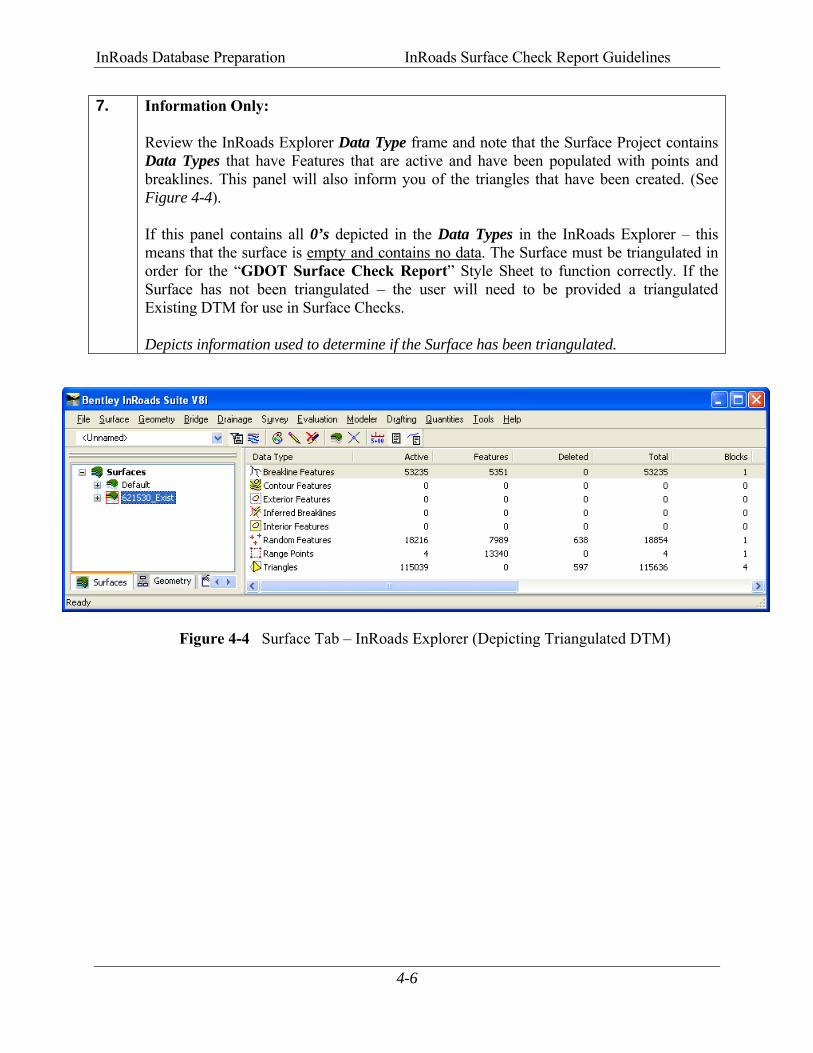
7. Information Only: Review the InRoads Explorer Data Type frame and note that the Surface Project contains Data Types that have Features that are active and have been populated with points and breaklines. This panel will also inform you of the triangles that have been created. (See Figure 4-4). If this panel contains all 0’s depicted in the Data Types in the InRoads Explorer – this means that the surface is empty and contains no data. The Surface must be triangulated in order for the “GDOT Surface Check Report” Style Sheet to function correctly. If the Surface has not been triangulated – the user will need to be provided a triangulated Existing DTM for use in Surface Checks. Depicts information used to determine if the Surface has been triangulated.
Figure 4-4 Surface Tab – InRoads Explorer (Depicting Triangulated DTM)

5ASC File Translation Process

ASC File Translation Process InRoads Surface Check Report Guidelines
5-1
5. ASC File Translation Process
The DTM Surface which is submitted by the Designer or Consultant is the surface model which will be compared to the field survey points (ASC Data) to ensure the accuracy of the DTM original terrain data for use in compliance checks. In order to import the field survey points for comparison to the DTM, an InRoads Survey Data Field Book (.FWD File) must be created and must be made active in order to import and translate the “RAW” ASC Data from Survey. In these Guidelines, an example Project 621530Z.fwd (Survey Data Field Book File) will be created. This active field book database will be used to import, generate and translate the “RAW ASC” data from Survey. InRoads contains an *ASC to InRoads Translator which converts the ASC file into a format that is usable for InRoads. The translator converts the .ASC file based on a format of Point Number, Easting, Northing, Elevation and Feature Code. After the ASC file is translated and imported into the Field Book, the data will then be imported into a Geometry Project. The importation into the Geometry Project will be discussed in the next Chapter 6. *Please Note: The field survey points, which will be collected by the Survey personnel for DTM mapping data verification, will consist of two SMI Codes (160 and 161). These SMI codes MUST be used in order for the ASC Translation process in InRoads to work and the GDOT Surface Check Report Style Sheet to translate and generate the points according to GDOT standards. This section covers the following topics:
• Create a Survey Data Field Book Project (Project 621530Z.fwd) • Save the Survey Data Field Book Project (Project 621530Z.fwd) • Translate and Import the ”RAW” ASC File • Review the Survey Data in the Field Book and correct errors as needed • View the Planimetric Survey Data in InRoads/MicroStation

ASC File Translation Process InRoads Surface Check Report Guidelines
5-2
5.1 Create 621530Z Survey Data Project (621530Z.fwd) Fieldbook An InRoads EXAMPLE Survey Data Field Book (621530Z.fwd) will be created and saved to the Project Folder. This Survey Data Field Book data will be used in the next Chapter 6 to create an .ALG (Geometry database).
8. If MicroStation and InRoads are not open, follow the steps depicted in the previous
Chapter 4 to open MicroStation and InRoads. Starts the MicroStation and InRoads Software Product(s).
Figure 5-1 InRoads Interface
9. Click on the Survey Tab (Located at the bottom – left hand side of the InRoads Explorer Interface). If this tab is not visible – use the scroll bars to scroll to the Survey Tab. Opens the Survey Tab in the InRoads Explorer Interface.
InRoads Explorer Interface
Survey TAB
Scroll Bars
ASC File Translation Process InRoads Surface Check Report Guidelines
5-3
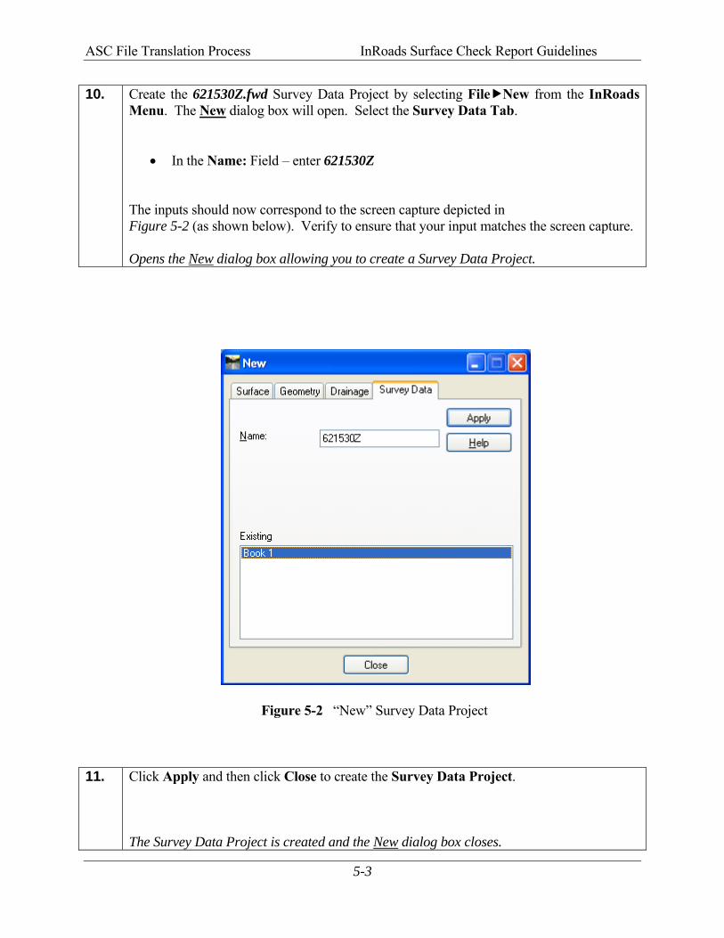
10. Create the 621530Z.fwd Survey Data Project by selecting File New from the InRoads Menu. The New dialog box will open. Select the Survey Data Tab.
• In the Name: Field – enter 621530Z The inputs should now correspond to the screen capture depicted in Figure 5-2 (as shown below). Verify to ensure that your input matches the screen capture.
Opens the New dialog box allowing you to create a Survey Data Project.
Figure 5-2 “New” Survey Data Project
11. Click Apply and then click Close to create the Survey Data Project.
The Survey Data Project is created and the New dialog box closes.
ASC File Translation Process InRoads Surface Check Report Guidelines
5-4
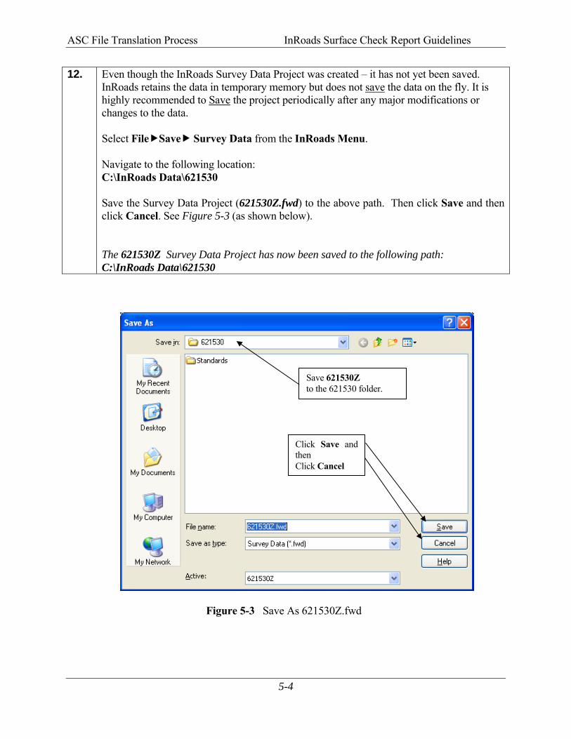
12. Even though the InRoads Survey Data Project was created – it has not yet been saved. InRoads retains the data in temporary memory but does not save the data on the fly. It is highly recommended to Save the project periodically after any major modifications or changes to the data.
Select File Save Survey Data from the InRoads Menu. Navigate to the following location: C:\InRoads Data\621530 Save the Survey Data Project (621530Z.fwd) to the above path. Then click Save and then click Cancel. See Figure 5-3 (as shown below). The 621530Z Survey Data Project has now been saved to the following path: C:\InRoads Data\621530
Figure 5-3 Save As 621530Z.fwd
Save 621530Z to the 621530 folder.
Click Save and then Click Cancel
ASC File Translation Process InRoads Surface Check Report Guidelines
5-5
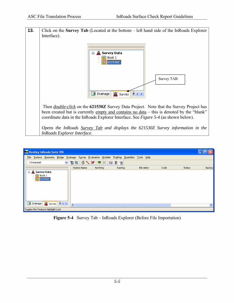
13. Click on the Survey Tab (Located at the bottom – left hand side of the InRoads Explorer Interface).
Then double-click on the 621530Z Survey Data Project. Note that the Survey Project has been created but is currently empty and contains no data – this is denoted by the “blank” coordinate data in the InRoads Explorer Interface. See Figure 5-4 (as shown below). Opens the InRoads Survey Tab and displays the 621530Z Survey information in the InRoads Explorer Interface.
Figure 5-4 Survey Tab – InRoads Explorer (Before File Importation)
Survey TAB
ASC File Translation Process InRoads Surface Check Report Guidelines
5-6
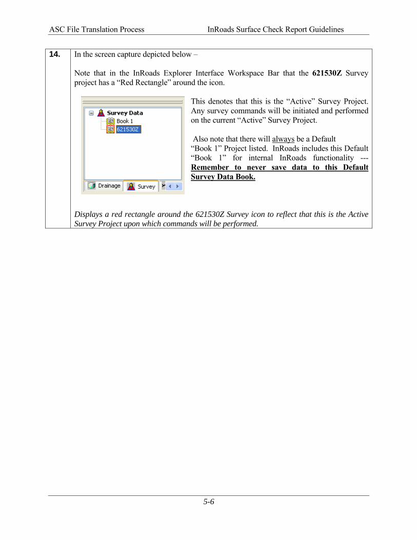
14. In the screen capture depicted below – Note that in the InRoads Explorer Interface Workspace Bar that the 621530Z Survey project has a “Red Rectangle” around the icon.
This denotes that this is the “Active” Survey Project. Any survey commands will be initiated and performed on the current “Active” Survey Project. Also note that there will always be a Default “Book 1” Project listed. InRoads includes this Default “Book 1” for internal InRoads functionality --- Remember to never save data to this Default Survey Data Book.
Displays a red rectangle around the 621530Z Survey icon to reflect that this is the Active Survey Project upon which commands will be performed.
ASC File Translation Process InRoads Surface Check Report Guidelines
5-7
5.2 Translate and Import the ASC “RAW” File In the following EXAMPLE – an ASC “RAW” Field Survey File will be translated and imported into the 621530Z.fwd field book by using the InRoads “Import Survey Data” command. After the data has been translated and imported – the Survey Data will be saved to the 621530Z.fwd Survey Project. You will need to copy the .ASC Check File to the Project Folder so that it will be in the C:\InRoads Data\621530 directory path.
15. For Information Only: Following is an example format of the GDOT standard ASC File which contains the “Check Points” which will be used to verify the accuracy of the DTM Data: (Point Number – Easting –Northing – Elevation—Feature Code) *PT NO. EAST NORTH ELEV. FEATURE CODE 48516 2005394.54239 1777879.31938 806.38649 F161 48517 2005415.72620 1777923.65596 808.18836 F161 48518 2005436.09385 1777966.44293 809.86092 F161 48519 2005457.52306 1778011.33705 811.52587 F161 48520 2005479.06942 1778056.60578 813.25172 F161 48521 2005500.44476 1778101.76749 814.92304 F161 48522 2005521.84541 1778146.87744 816.26879 F161 48523 2005542.86560 1778190.98679 817.49900 F161 Depicts “Example” format of standard GDOT ASC File.
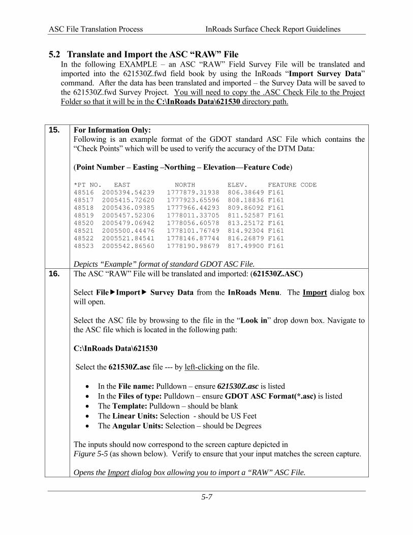
16. The ASC “RAW” File will be translated and imported: (621530Z.ASC) Select File Import Survey Data from the InRoads Menu. The Import dialog box will open. Select the ASC file by browsing to the file in the “Look in” drop down box. Navigate to the ASC file which is located in the following path: C:\InRoads Data\621530 Select the 621530Z.asc file --- by left-clicking on the file.
• In the File name: Pulldown – ensure 621530Z.asc is listed • In the Files of type: Pulldown – ensure GDOT ASC Format(*.asc) is listed • The Template: Pulldown – should be blank • The Linear Units: Selection - should be US Feet • The Angular Units: Selection – should be Degrees
The inputs should now correspond to the screen capture depicted in Figure 5-5 (as shown below). Verify to ensure that your input matches the screen capture.
Opens the Import dialog box allowing you to import a “RAW” ASC File.
ASC File Translation Process InRoads Surface Check Report Guidelines
5-8
Figure 5-5 Import ASC Translator
17. Click Import.
(This command selects the data to be imported.) Click Close. (The Survey Data is actually imported when the Close command is selected.) Please Be Patient! It may take a while for the ASC data to import depending on the size of the file! Once the data is imported – the Import dialog box will close automatically. The “RAW”ASC File data is translated and imported into the 621530Z Survey Project.
ASC File Translation Process InRoads Surface Check Report Guidelines
5-9
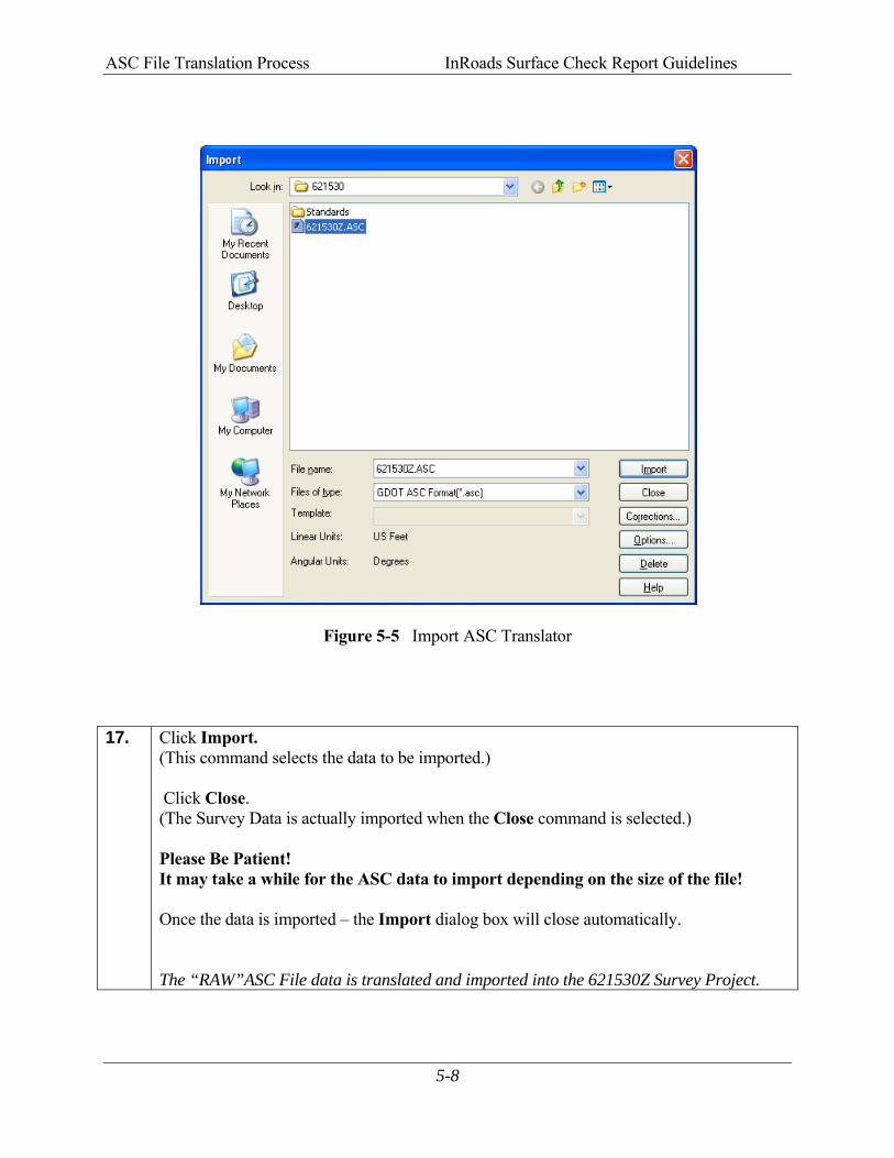
18. The “RAW” ASC File data is now imported into the 621530Z Survey Project. Click on the Survey Tab (Located at the bottom – left hand side of the InRoads Explorer Interface) and then double-click on the 621530Z Survey Project. A File folder will appear. Double-click on the File folder. Review the InRoads Explorer data frame and note that the Survey Project now contains point data and coordinate information. Your InRoads Explorer Interface should look similar to the screen capture shown below (See Figure 5-6). Opens the InRoads Survey Tab and displays the 621530Z Survey Data information in the InRoads Explorer Interface.
Figure 5-6 Survey Tab – InRoads Explorer (After File Importation)

ASC File Translation Process InRoads Surface Check Report Guidelines
5-10
19. Even though the “RAW” ASC data has been imported into the InRoads Survey Project (621530Z.fwd) – the data has not yet been saved. As mentioned previously, InRoads retains the data in temporary memory but does not save the data on the fly. Whenever a change has been made to an InRoads Survey Project – it is advisable to Save the project and its associated modifications or changes.
Select File Save Survey Data from the InRoads Menu. Please Note: (The “Save As” dialog box may not appear because the Survey Project has already been saved initially). The Survey Project (621530Z.fwd) will be saved to the following path: C:\InRoads Data\621530 Note that the InRoads Status Bar (Located at the bottom of the InRoads Interface) will depict a message when the Survey Project has been saved. (See screen capture below):
The 621530Z Survey Project has now been saved to the following path: C:\InRoads Data\621530
Survey Project Saved
ASC File Translation Process InRoads Surface Check Report Guidelines
5-11
5.3 Review the Survey Data in the Survey Field Book In the following Section – the ASC Field Survey data will be reviewed for accuracy in the Survey field book to determine if there was any erroneous data introduced in the ASC file. Although the Field Book is a good tool to utilize for reviewing and determining error in the data – it is highly advisable to use this field book as a review tool only. If any errors are found during the review – the user needs to make any corrections or adjustments of the data in the original ASC file or recompile the survey data contained in the data collector to create a new ASC file. The field book can be utilized to determine the validity of many aspects regarding point data represented in the ASC file. Although this section does not demonstrate all of the review functions contained in the field book – following are some of the tools available for point/alignment verification: • Unrecognized Feature Codes which are not found in InRoads (will be highlighted in Red) • Errors in Elevation (Busts in elevations) • One Point on Chain Check As mentioned previously if any errors are found during the review of the field book data – all corrections should be made in the original ASC file or data collector.
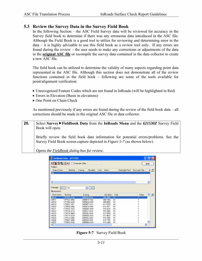
20. Select Survey Fieldbook Data from the InRoads Menu and the 621530Z Survey Field
Book will open. Briefly review the field book data information for potential errors/problems. See the Survey Field Book screen capture depicted in Figure 5-7 (as shown below). Opens the Fieldbook dialog box for review.
Figure 5-7 Survey Field Book
ASC File Translation Process InRoads Surface Check Report Guidelines
5-12
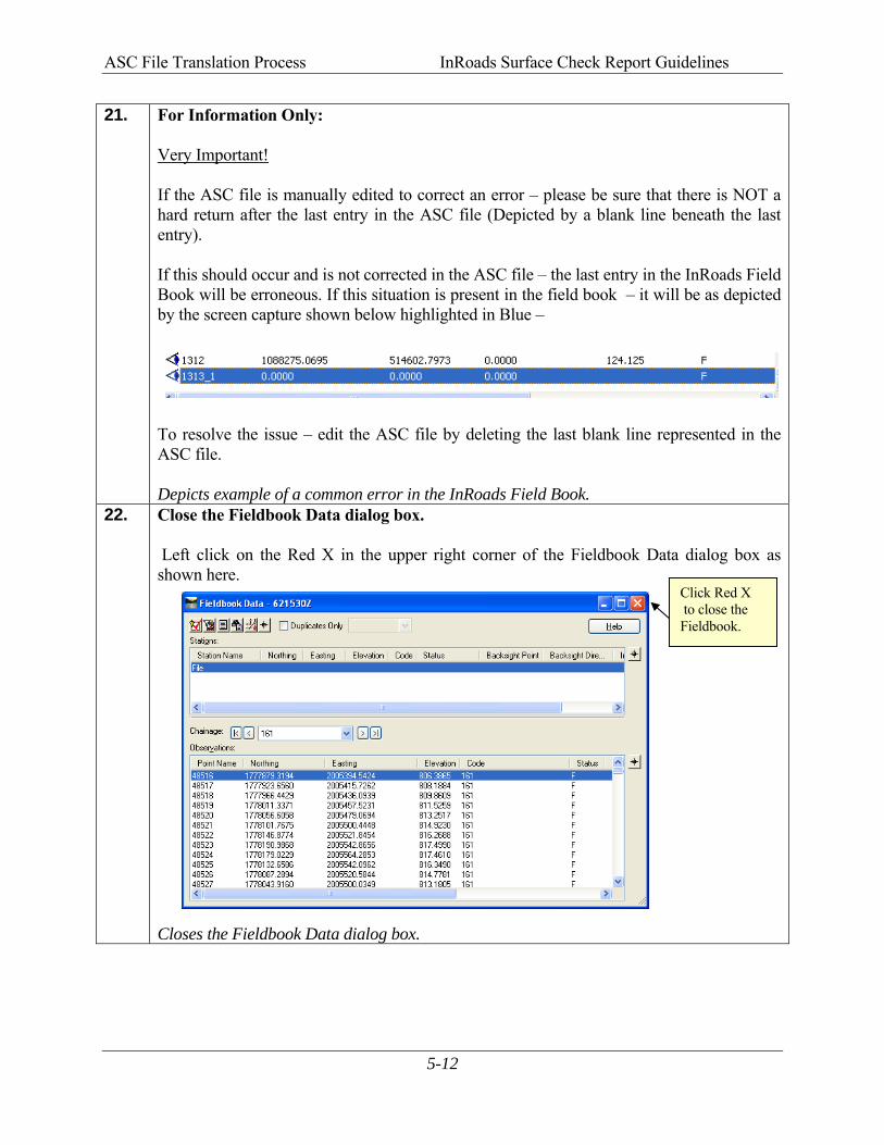
21. For Information Only: Very Important! If the ASC file is manually edited to correct an error – please be sure that there is NOT a hard return after the last entry in the ASC file (Depicted by a blank line beneath the last entry). If this should occur and is not corrected in the ASC file – the last entry in the InRoads Field Book will be erroneous. If this situation is present in the field book – it will be as depicted by the screen capture shown below highlighted in Blue – To resolve the issue – edit the ASC file by deleting the last blank line represented in the ASC file. Depicts example of a common error in the InRoads Field Book.
22. Close the Fieldbook Data dialog box. Left click on the Red X in the upper right corner of the Fieldbook Data dialog box as shown here. Closes the Fieldbook Data dialog box.
Click Red X to close the Fieldbook.
ASC File Translation Process InRoads Surface Check Report Guidelines
5-13
5.4 View the Planimetric Survey Data When the Survey Data is imported into the Survey Field Book, the data can be viewed as Planimetric data in MicroStation. Please Note: At this time - the data can be viewed only. This data is not actually written as Graphics to the DGN file. The user may zoom in or out in MicroStation but actual manipulations to the data cannot be initiated because it has not yet been imported into a Surface and/or Geometry database. 23. View the selected Features in the [MicroStation Software] by using the following
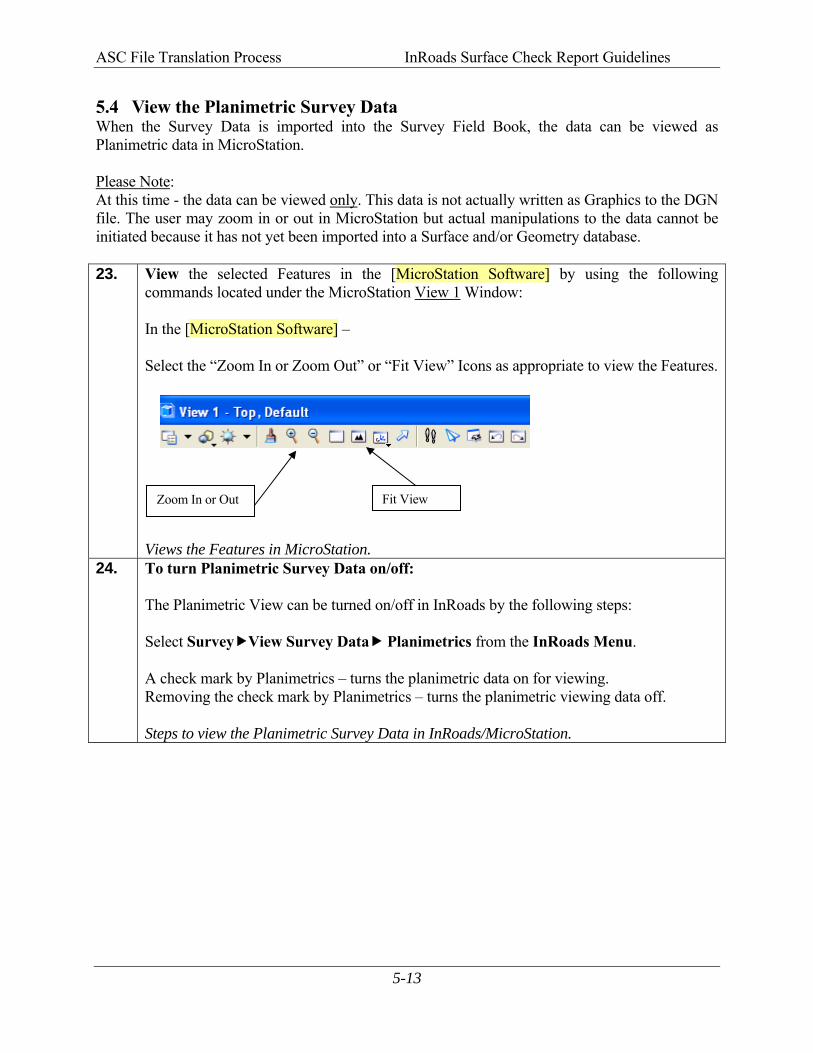
commands located under the MicroStation View 1 Window: In the [MicroStation Software] – Select the “Zoom In or Zoom Out” or “Fit View” Icons as appropriate to view the Features. Views the Features in MicroStation.
24. To turn Planimetric Survey Data on/off: The Planimetric View can be turned on/off in InRoads by the following steps: Select Survey View Survey Data Planimetrics from the InRoads Menu. A check mark by Planimetrics – turns the planimetric data on for viewing. Removing the check mark by Planimetrics – turns the planimetric viewing data off. Steps to view the Planimetric Survey Data in InRoads/MicroStation.
Fit ViewZoom In or Out

ASC File Translation Process InRoads Surface Check Report Guidelines
6ALG (Geometry Project) Import Process

ALG (Geometry Project) Import Process InRoads Surface Check Report Guidelines
6-2
6. ALG (Geometry Project) Import Process
**Please Note that when using the “GDOT Surface Check Report” Style Sheet and its associated processes, a different method of Survey Import is utilized. In most Survey Processing Procedures – Topo data is imported into the Surface Project (.DTM) and the Property data is imported into the Geometry Project (.ALG). When using the “GDOT Surface Check Report” Style Sheet process – both the MPCKGRD and MPCKPAV Feature Code Points are always imported into the Geometry Project (.ALG). If the points are not imported into a Geometry Project (.ALG) – the “GDOT Surface Check Report” Style Sheet will not function.
In the previous Chapter 5, the field survey data was translated and imported into InRoads by using a Survey Project (an .FWD Survey Field Book). The next Chapter depicts the process of creating a Geometry Project (.ALG) and importing the translated survey data into this database. The survey data which is imported into the Geometry Project (.ALG) will consist of the MPCKGRD and MPCKPAV Feature code points. These points are used to compare the associated point data in the Existing surface model to ensure that the DTM surface is within compliance. In order to automate this process - Survey Style Filters have been created which automatically “filters” the data so that the appropriate data will import into the Geometry Database. In the case of the “GDOT Surface Check Report” Style Sheet compliance checks – these filters will need to be turned OFF for the Geometry Project import. The following Section depicts the procedures to create the Geometry Project (.ALG) and the process of importing the Survey Data into the database. This section covers the following topics:
• Create and Import data into an InRoads ALG (Geometry Database Project) • Learn how to use Survey Style Filters and Feature Filter “Locks” • View the Graphical Geometry Information
ALG (Geometry Project) Import Process InRoads Surface Check Report Guidelines
6-3
6.1 Create a Geometry Project Database (.ALG)
In this Chapter you will be creating a Geometry Project Database. This database will be used to import the Point Data information contained in the Survey Field Book (.FWD) into the Geometry Project Database (.ALG). 25. If MicroStation and InRoads are not open, follow the steps depicted in the previous
Chapter 4 to open MicroStation and InRoads. Starts the MicroStation and InRoads Software Product(s).
26. Information Only: Make sure the following files are open – Substitute applicable PI# as required.
• 621530_Exist.dtm --- the Existing Surface which is to be verified • 621530Z.fwd --- the “Check” Survey Points obtained from the ASC File
Ensures the Existing DTM and Survey Field Book databases are open.
27. Click Tools Locks from the InRoads pull-down menu. Ensure that the following Lock is turned OFF. There should NOT be a check mark next to the following: Feature Filter is not checked This is an important step. If the Feature Filter is not turned off (has no check mark next to it) – the Survey Style Filter will not work correctly… Ensures that the appropriate Lock is turned OFF.
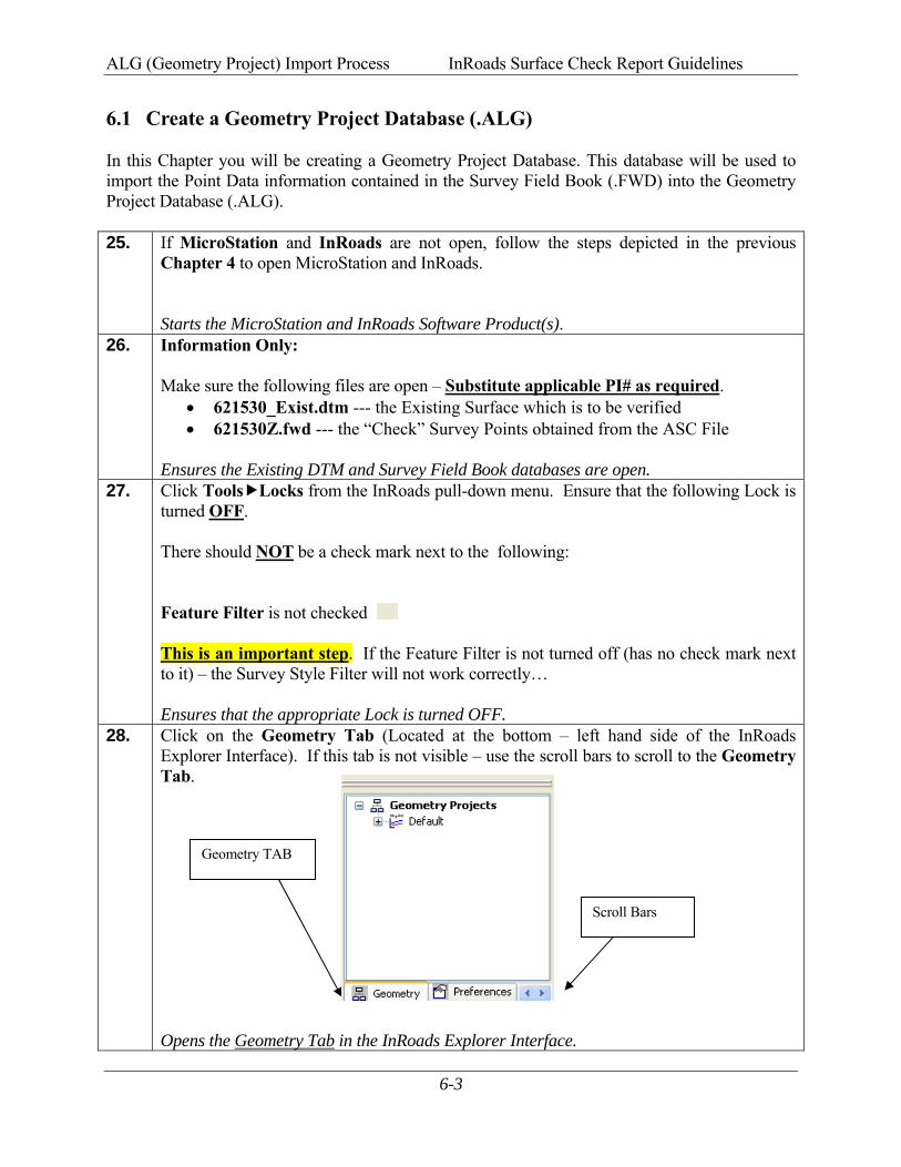
28. Click on the Geometry Tab (Located at the bottom – left hand side of the InRoads Explorer Interface). If this tab is not visible – use the scroll bars to scroll to the Geometry Tab. Opens the Geometry Tab in the InRoads Explorer Interface.
Geometry TAB
Scroll Bars
ALG (Geometry Project) Import Process InRoads Surface Check Report Guidelines
6-4
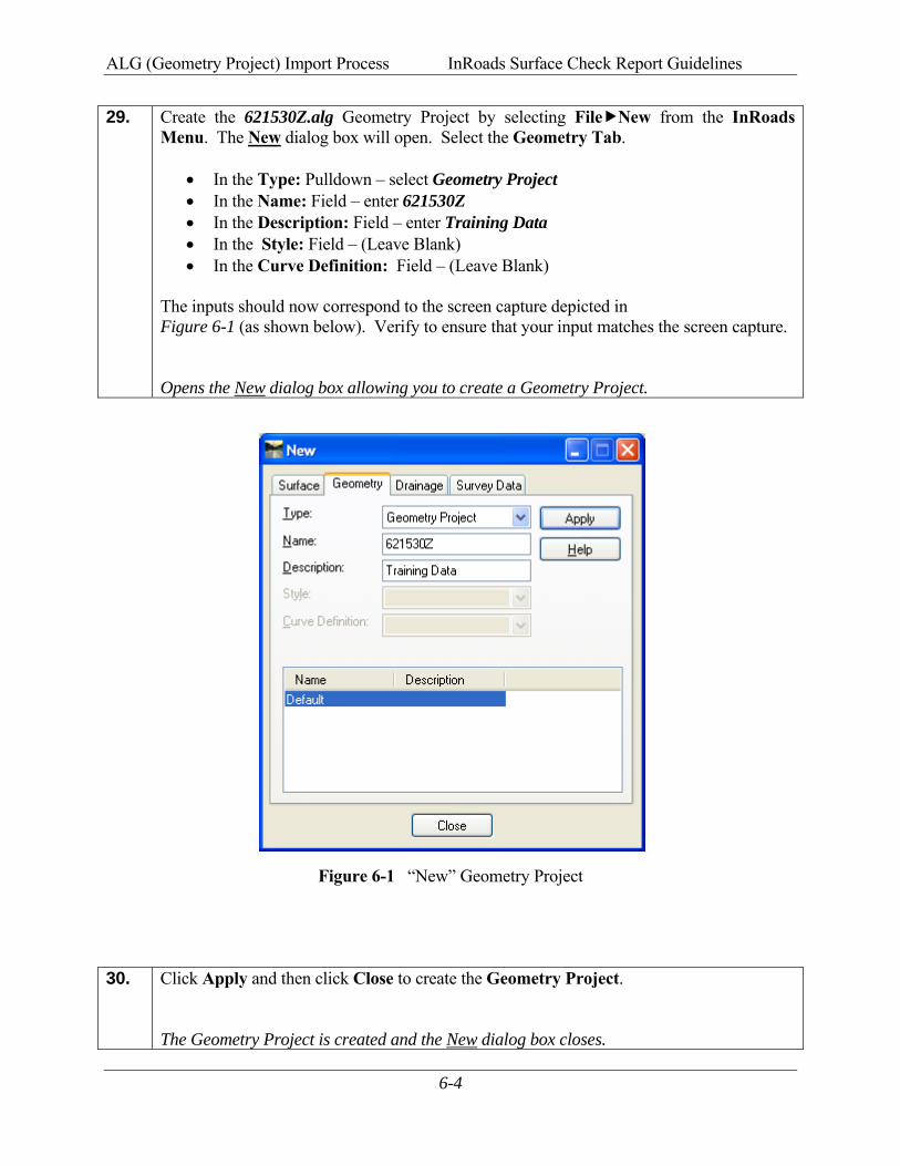
29. Create the 621530Z.alg Geometry Project by selecting File New from the InRoads Menu. The New dialog box will open. Select the Geometry Tab.
• In the Type: Pulldown – select Geometry Project • In the Name: Field – enter 621530Z • In the Description: Field – enter Training Data • In the Style: Field – (Leave Blank) • In the Curve Definition: Field – (Leave Blank)
The inputs should now correspond to the screen capture depicted in Figure 6-1 (as shown below). Verify to ensure that your input matches the screen capture.
Opens the New dialog box allowing you to create a Geometry Project.
Figure 6-1 “New” Geometry Project
30. Click Apply and then click Close to create the Geometry Project.
The Geometry Project is created and the New dialog box closes.
ALG (Geometry Project) Import Process InRoads Surface Check Report Guidelines
6-5
31. Even though the InRoads Geometry Project was created – it has not yet been saved. InRoads retains the data in temporary memory but does not save the data on the fly. It is highly recommended to Save the project periodically after any major modifications or changes to the data.
Select File Save Geometry Project from the InRoads Menu. Navigate to the following location: C:\InRoads Data\621530 Save the Geometry Project (621530Z.alg) to the above path and then click Save and then click Cancel. See Figure 6-2 (as shown below). The 621530Z Geometry Project has now been saved to the following path: C:\InRoads Data\621530
Figure 6-2 Save As 621530Z.alg
Save 621530Z.alg to this path.
Click Save and then Click Cancel
ALG (Geometry Project) Import Process InRoads Surface Check Report Guidelines
6-6
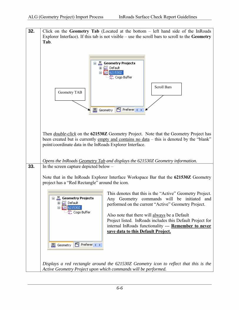
32. Click on the Geometry Tab (Located at the bottom – left hand side of the InRoads Explorer Interface). If this tab is not visible – use the scroll bars to scroll to the Geometry Tab. Then double-click on the 621530Z Geometry Project. Note that the Geometry Project has been created but is currently empty and contains no data – this is denoted by the “blank” point/coordinate data in the InRoads Explorer Interface. Opens the InRoads Geometry Tab and displays the 621530Z Geometry information.
33. In the screen capture depicted below – Note that in the InRoads Explorer Interface Workspace Bar that the 621530Z Geometry project has a “Red Rectangle” around the icon.
This denotes that this is the “Active” Geometry Project. Any Geometry commands will be initiated and performed on the current “Active” Geometry Project. Also note that there will always be a Default Project listed. InRoads includes this Default Project for internal InRoads functionality --- Remember to never save data to this Default Project.
Displays a red rectangle around the 621530Z Geometry icon to reflect that this is the Active Geometry Project upon which commands will be performed.
Geometry TAB Scroll Bars
ALG (Geometry Project) Import Process InRoads Surface Check Report Guidelines
6-7
6.2 Import Survey Data into the Geometry Project (.ALG)
In this Chapter you will be creating a Geometry Project Database. This database will be used to import the Point Data information contained in the Survey Field Book (.FWD) into the Geometry Project Database (.ALG). The following Section depicts the process of importing in the Survey Data (MPCKGRD and MPCKPAV Check Points) into the 621530Z Geometry Project. 34. Important Step!
Click Tools Locks from the InRoads pull-down menu. Ensure that the Feature Filter Lock is turned OFF. There should NOT be a check mark next to the Feature Filter Lock. Ensures that the Feature Filter Lock is turned OFF.
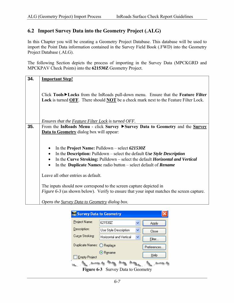
35. From the InRoads Menu - click Survey Survey Data to Geometry and the Survey Data to Geometry dialog box will appear:
• In the Project Name: Pulldown – select 621530Z • In the Description: Pulldown – select the default Use Style Description • In the Curve Stroking: Pulldown – select the default Horizontal and Vertical • In the Duplicate Names: radio button – select default of Rename
Leave all other entries as default. The inputs should now correspond to the screen capture depicted in Figure 6-3 (as shown below). Verify to ensure that your input matches the screen capture.
Opens the Survey Data to Geometry dialog box.
Figure 6-3 Survey Data to Geometry
ALG (Geometry Project) Import Process InRoads Surface Check Report Guidelines
6-8
36. Click Apply and then click Close. The Survey Data (Check Points) will be imported into the 621530Z Geometry Project and the Survey Data to Geometry dialog box will close. The Survey Data is imported and the Survey Data to Geometry dialog box closes.
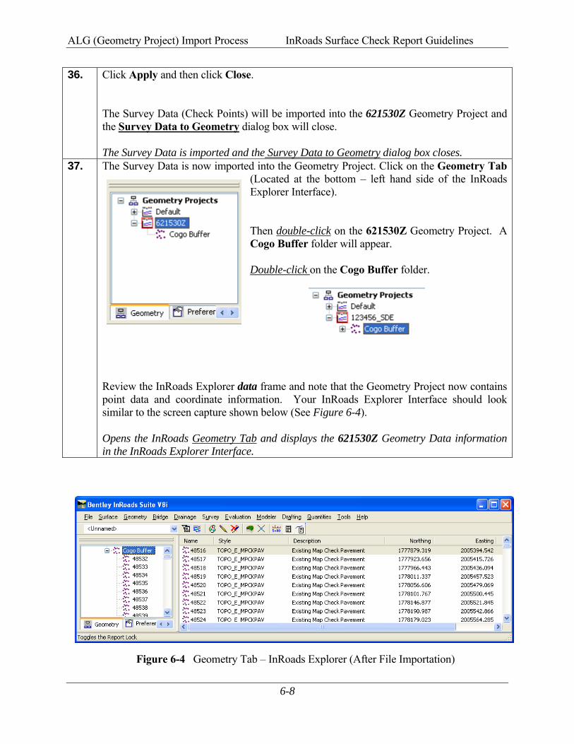
37. The Survey Data is now imported into the Geometry Project. Click on the Geometry Tab (Located at the bottom – left hand side of the InRoads Explorer Interface). Then double-click on the 621530Z Geometry Project. A Cogo Buffer folder will appear. Double-click on the Cogo Buffer folder.
Review the InRoads Explorer data frame and note that the Geometry Project now contains point data and coordinate information. Your InRoads Explorer Interface should look similar to the screen capture shown below (See Figure 6-4). Opens the InRoads Geometry Tab and displays the 621530Z Geometry Data information in the InRoads Explorer Interface.
Figure 6-4 Geometry Tab – InRoads Explorer (After File Importation)

ALG (Geometry Project) Import Process InRoads Surface Check Report Guidelines
6-9
38. Save the InRoads Geometry Project: Even though the Survey data has been imported into the InRoads Geometry Project (621530Z.alg) – the data has not yet been saved. As mentioned previously, InRoads retains the data in temporary memory but does not save the data on the fly. Whenever a change has been made to an InRoads Geometry Project – it is advisable to Save the project and its associated modifications or changes.
Select File Save Geometry Project from the InRoads Menu. Please Note: (The “Save As” dialog box may not appear because the Geometry Project has already been saved initially). The Geometry Project (621530Z.alg) will be saved to the following path: C:\InRoads Data\621530 Note that the InRoads Status Bar (Located at the bottom of the InRoads Interface) will depict a message when the Geometry Project has been saved. (See screen capture below):
The 621530Z Geometry Project has now been saved to the following path: C:\InRoads Data\621530
Geometry Project Saved
ALG (Geometry Project) Import Process InRoads Surface Check Report Guidelines
6-10
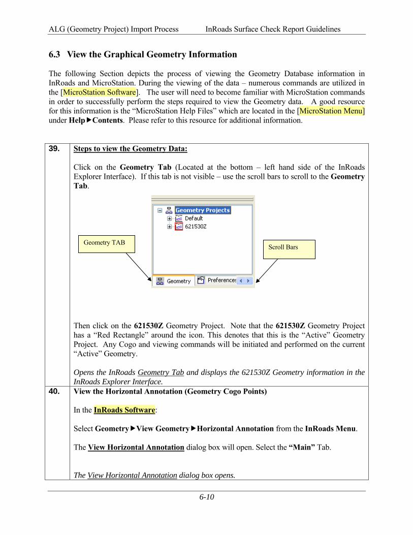
6.3 View the Graphical Geometry Information The following Section depicts the process of viewing the Geometry Database information in InRoads and MicroStation. During the viewing of the data – numerous commands are utilized in the [MicroStation Software]. The user will need to become familiar with MicroStation commands in order to successfully perform the steps required to view the Geometry data. A good resource for this information is the “MicroStation Help Files” which are located in the [MicroStation Menu] under Help Contents. Please refer to this resource for additional information. 39. Steps to view the Geometry Data:
Click on the Geometry Tab (Located at the bottom – left hand side of the InRoads Explorer Interface). If this tab is not visible – use the scroll bars to scroll to the Geometry Tab. Then click on the 621530Z Geometry Project. Note that the 621530Z Geometry Project has a “Red Rectangle” around the icon. This denotes that this is the “Active” Geometry Project. Any Cogo and viewing commands will be initiated and performed on the current “Active” Geometry. Opens the InRoads Geometry Tab and displays the 621530Z Geometry information in the InRoads Explorer Interface.
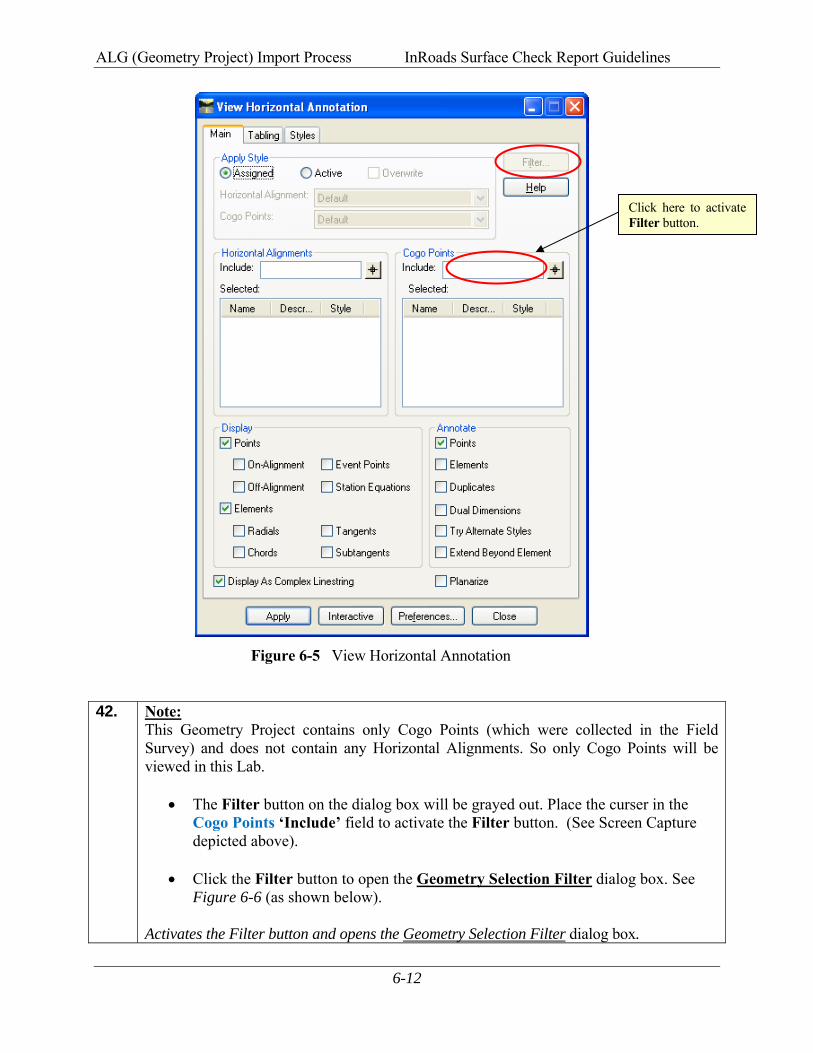
40. View the Horizontal Annotation (Geometry Cogo Points) In the InRoads Software: Select Geometry View Geometry Horizontal Annotation from the InRoads Menu. The View Horizontal Annotation dialog box will open. Select the “Main” Tab. The View Horizontal Annotation dialog box opens.
Geometry TAB Scroll Bars
ALG (Geometry Project) Import Process InRoads Surface Check Report Guidelines
6-11
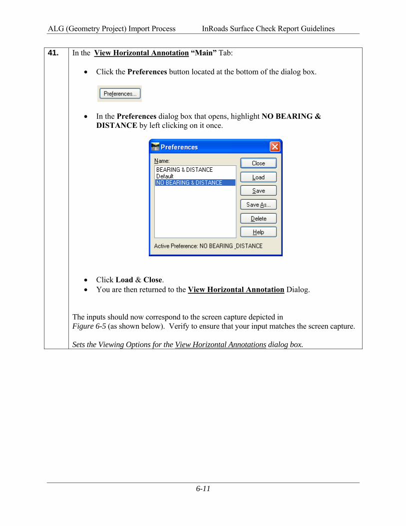
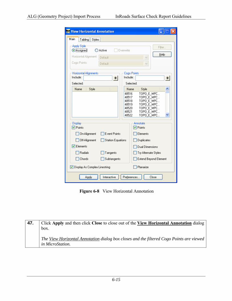
41. In the View Horizontal Annotation “Main” Tab:
• Click the Preferences button located at the bottom of the dialog box.
• In the Preferences dialog box that opens, highlight NO BEARING & DISTANCE by left clicking on it once.
• Click Load & Close. • You are then returned to the View Horizontal Annotation Dialog.
The inputs should now correspond to the screen capture depicted in Figure 6-5 (as shown below). Verify to ensure that your input matches the screen capture.
Sets the Viewing Options for the View Horizontal Annotations dialog box.
ALG (Geometry Project) Import Process InRoads Surface Check Report Guidelines
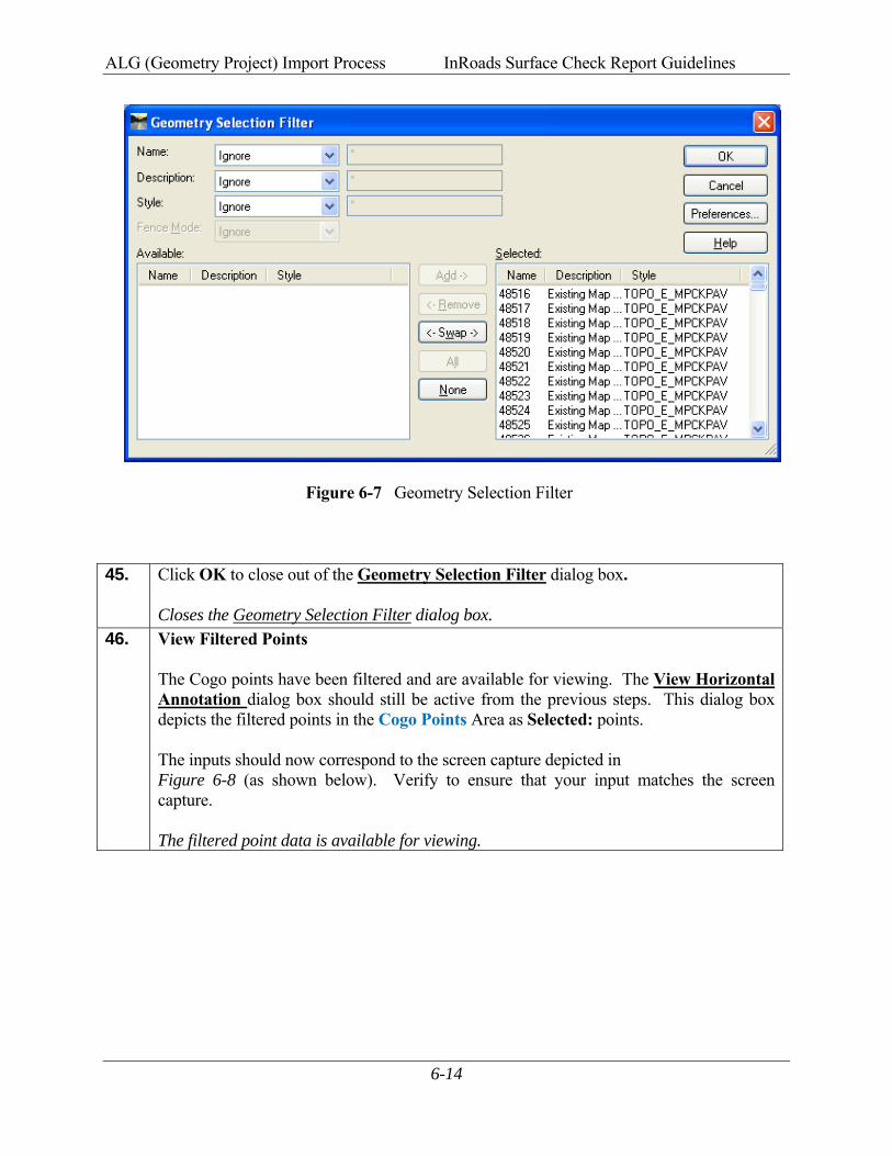
6-12
Figure 6-5 View Horizontal Annotation 42. Note:
This Geometry Project contains only Cogo Points (which were collected in the Field Survey) and does not contain any Horizontal Alignments. So only Cogo Points will be viewed in this Lab.
• The Filter button on the dialog box will be grayed out. Place the curser in the Cogo Points ‘Include’ field to activate the Filter button. (See Screen Capture depicted above).
• Click the Filter button to open the Geometry Selection Filter dialog box. See
Figure 6-6 (as shown below). Activates the Filter button and opens the Geometry Selection Filter dialog box.
Click here to activate Filter button.
ALG (Geometry Project) Import Process InRoads Surface Check Report Guidelines
6-13
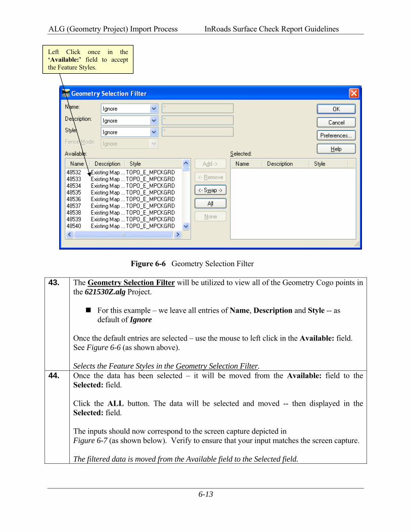
Figure 6-6 Geometry Selection Filter
43. The Geometry Selection Filter will be utilized to view all of the Geometry Cogo points in the 621530Z.alg Project.
For this example – we leave all entries of Name, Description and Style -- as default of Ignore
Once the default entries are selected – use the mouse to left click in the Available: field. See Figure 6-6 (as shown above). Selects the Feature Styles in the Geometry Selection Filter.
44. Once the data has been selected – it will be moved from the Available: field to the Selected: field. Click the ALL button. The data will be selected and moved -- then displayed in the Selected: field. The inputs should now correspond to the screen capture depicted in Figure 6-7 (as shown below). Verify to ensure that your input matches the screen capture. The filtered data is moved from the Available field to the Selected field.
Left Click once in the ‘Available:’ field to accept the Feature Styles.
ALG (Geometry Project) Import Process InRoads Surface Check Report Guidelines
6-14
Figure 6-7 Geometry Selection Filter
45. Click OK to close out of the Geometry Selection Filter dialog box. Closes the Geometry Selection Filter dialog box.
46. View Filtered Points The Cogo points have been filtered and are available for viewing. The View Horizontal Annotation dialog box should still be active from the previous steps. This dialog box depicts the filtered points in the Cogo Points Area as Selected: points. The inputs should now correspond to the screen capture depicted in Figure 6-8 (as shown below). Verify to ensure that your input matches the screen capture.
The filtered point data is available for viewing.
ALG (Geometry Project) Import Process InRoads Surface Check Report Guidelines
6-15
Figure 6-8 View Horizontal Annotation
47. Click Apply and then click Close to close out of the View Horizontal Annotation dialog box. The View Horizontal Annotation dialog box closes and the filtered Cogo Points are viewed in MicroStation.
ALG (Geometry Project) Import Process InRoads Surface Check Report Guidelines
6-16
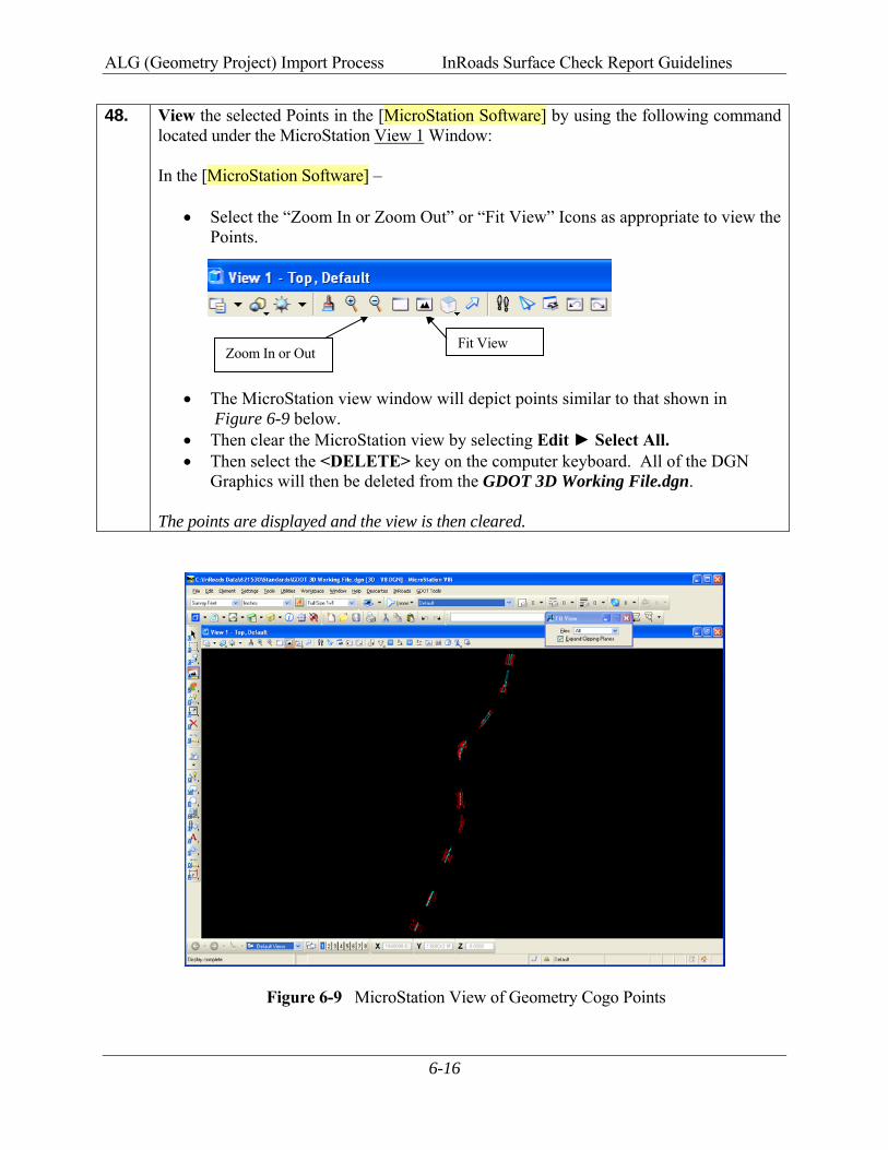
48. View the selected Points in the [MicroStation Software] by using the following command located under the MicroStation View 1 Window: In the [MicroStation Software] –
• Select the “Zoom In or Zoom Out” or “Fit View” Icons as appropriate to view the Points.
• The MicroStation view window will depict points similar to that shown in Figure 6-9 below.
• Then clear the MicroStation view by selecting Edit ► Select All. • Then select the <DELETE> key on the computer keyboard. All of the DGN
Graphics will then be deleted from the GDOT 3D Working File.dgn. The points are displayed and the view is then cleared.
Figure 6-9 MicroStation View of Geometry Cogo Points
Fit ViewZoom In or Out
7GDOT Surface Check Report Procedures
GDOT Surface Check Report Procedures InRoads Surface Check Report Guidelines
7-1
7. GDOT Surface Check Report Procedures
In the previous Chapter 6, the field survey data was imported into the Geometry Project and viewed. The field survey “check” data is now ready to utilize in the “GDOT Surface Check Report” Style Sheet. The following Chapter depicts the procedures for creating the “GDOT Surface Check Report” Style Sheet to determine the tolerance and compliance of the DTM Surface Data provided by the Designer or Consultant.
49. For Information Only: (Substitute the appropriate PI # as required)
A. The Surface Project (621530_Exist.dtm) is the Existing DTM. This is the Surface information which is to be verified for accuracy.
B. The Survey Field Book (621530Z.fwd) is the field surveyed shots obtained by translating the “Check Points” ASC file into a Field Book format. These field shots are compared to the DTM to verify that the DTM is accurate and corresponds (within a specified tolerance) to the field points.
C. The Geometry Project (621530Z.alg) contains only the Field Points (from the Survey Field Book). The field points must be imported into a Geometry Project in order to use the Surface Check Report.
50. Click Tools XML Reports Surface Check and the Surface Check Report dialog
box will appear: The Surface Check Report dialog box appears.
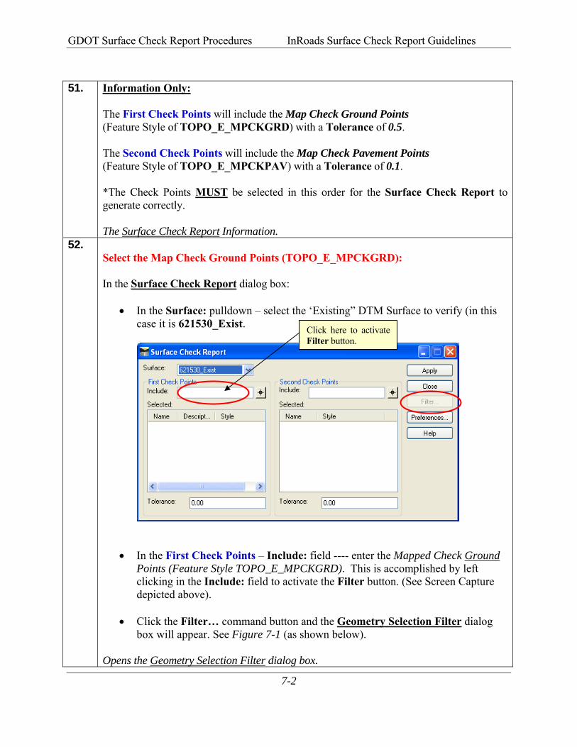
GDOT Surface Check Report Procedures InRoads Surface Check Report Guidelines
7-2
51. Information Only:
The First Check Points will include the Map Check Ground Points (Feature Style of TOPO_E_MPCKGRD) with a Tolerance of 0.5. The Second Check Points will include the Map Check Pavement Points (Feature Style of TOPO_E_MPCKPAV) with a Tolerance of 0.1. *The Check Points MUST be selected in this order for the Surface Check Report to generate correctly. The Surface Check Report Information.
52. Select the Map Check Ground Points (TOPO_E_MPCKGRD): In the Surface Check Report dialog box:
• In the Surface: pulldown – select the ‘Existing” DTM Surface to verify (in this case it is 621530_Exist.
• In the First Check Points – Include: field ---- enter the Mapped Check Ground Points (Feature Style TOPO_E_MPCKGRD). This is accomplished by left clicking in the Include: field to activate the Filter button. (See Screen Capture depicted above).
• Click the Filter… command button and the Geometry Selection Filter dialog box will appear. See Figure 7-1 (as shown below).
Opens the Geometry Selection Filter dialog box.
Click here to activate Filter button.
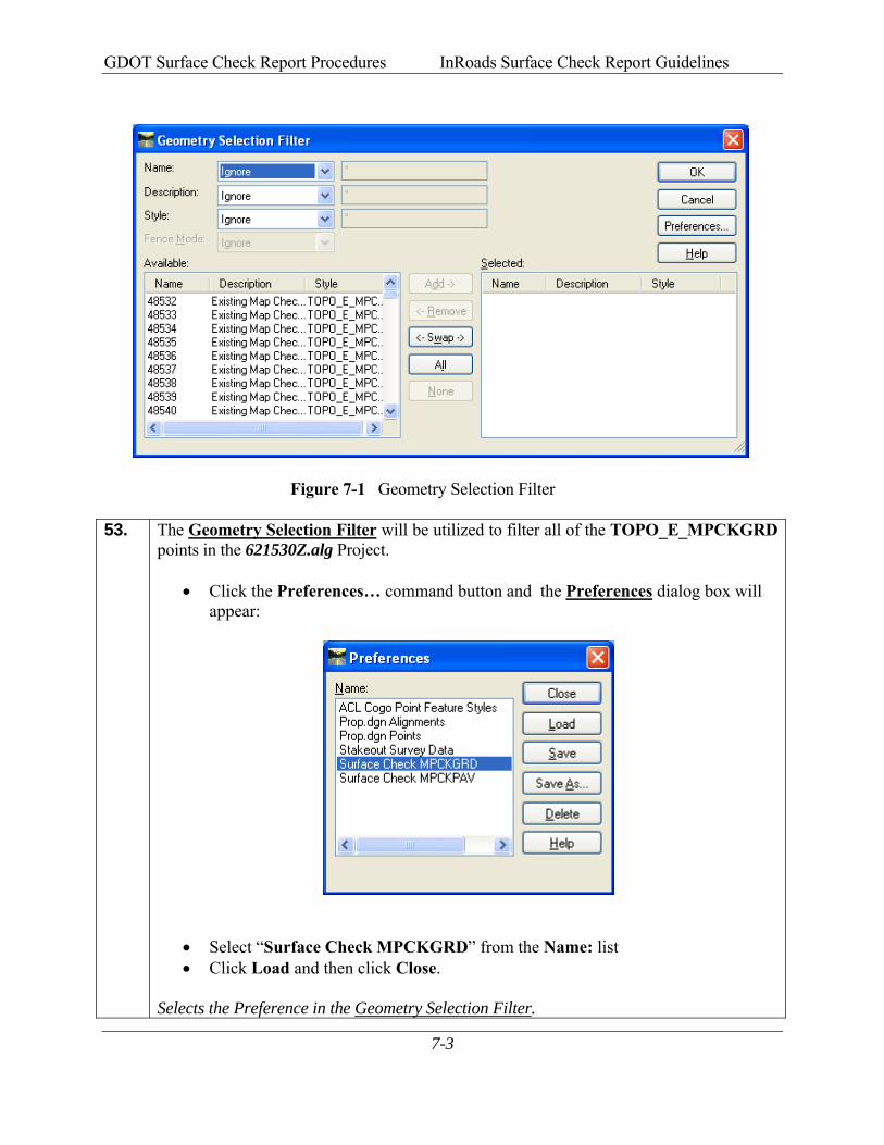
GDOT Surface Check Report Procedures InRoads Surface Check Report Guidelines
7-3
Figure 7-1 Geometry Selection Filter
53. The Geometry Selection Filter will be utilized to filter all of the TOPO_E_MPCKGRD points in the 621530Z.alg Project.
• Click the Preferences… command button and the Preferences dialog box will appear:
• Select “Surface Check MPCKGRD” from the Name: list • Click Load and then click Close.
Selects the Preference in the Geometry Selection Filter.
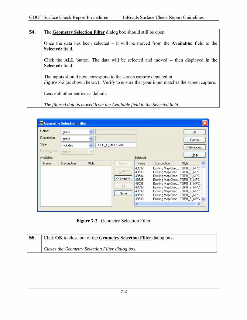
GDOT Surface Check Report Procedures InRoads Surface Check Report Guidelines
7-4
54. The Geometry Selection Filter dialog box should still be open. Once the data has been selected – it will be moved from the Available: field to the Selected: field. Click the ALL button. The data will be selected and moved -- then displayed in the Selected: field. The inputs should now correspond to the screen capture depicted in Figure 7-2 (as shown below). Verify to ensure that your input matches the screen capture. Leave all other entries as default. The filtered data is moved from the Available field to the Selected field.
Figure 7-2 Geometry Selection Filter
55. Click OK to close out of the Geometry Selection Filter dialog box.
Closes the Geometry Selection Filter dialog box.
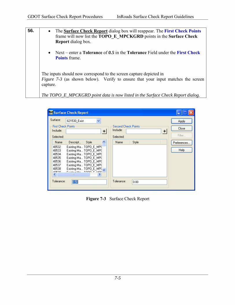
GDOT Surface Check Report Procedures InRoads Surface Check Report Guidelines
7-5
56. • The Surface Check Report dialog box will reappear. The First Check Points frame will now list the TOPO_E_MPCKGRD points in the Surface Check Report dialog box.
• Next – enter a Tolerance of 0.5 in the Tolerance Field under the First Check Points frame.
The inputs should now correspond to the screen capture depicted in Figure 7-3 (as shown below). Verify to ensure that your input matches the screen capture. The TOPO_E_MPCKGRD point data is now listed in the Surface Check Report dialog.
Figure 7-3 Surface Check Report
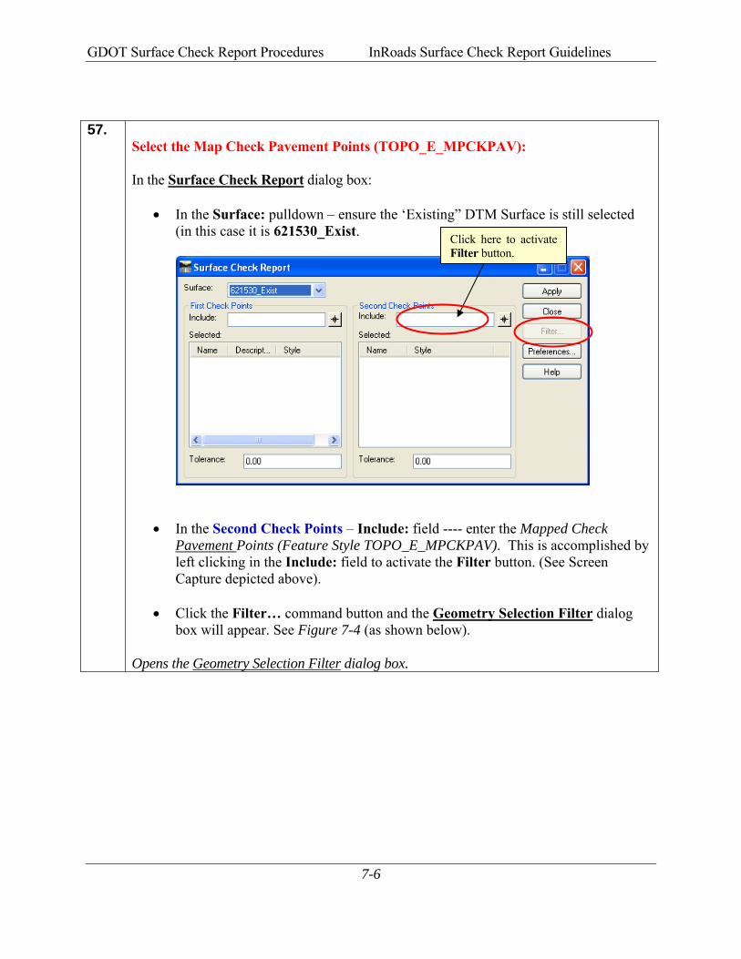
GDOT Surface Check Report Procedures InRoads Surface Check Report Guidelines
7-6
57. Select the Map Check Pavement Points (TOPO_E_MPCKPAV): In the Surface Check Report dialog box:
• In the Surface: pulldown – ensure the ‘Existing” DTM Surface is still selected (in this case it is 621530_Exist.
• In the Second Check Points – Include: field ---- enter the Mapped Check Pavement Points (Feature Style TOPO_E_MPCKPAV). This is accomplished by left clicking in the Include: field to activate the Filter button. (See Screen Capture depicted above).
• Click the Filter… command button and the Geometry Selection Filter dialog box will appear. See Figure 7-4 (as shown below).
Opens the Geometry Selection Filter dialog box.
Click here to activate Filter button.
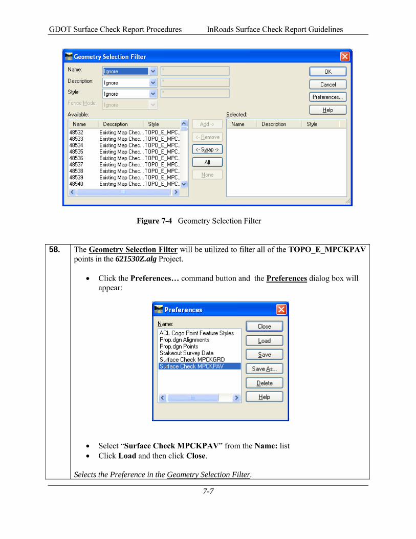
GDOT Surface Check Report Procedures InRoads Surface Check Report Guidelines
7-7
Figure 7-4 Geometry Selection Filter
58. The Geometry Selection Filter will be utilized to filter all of the TOPO_E_MPCKPAV
points in the 621530Z.alg Project.
• Click the Preferences… command button and the Preferences dialog box will appear:
• Select “Surface Check MPCKPAV” from the Name: list • Click Load and then click Close.
Selects the Preference in the Geometry Selection Filter.
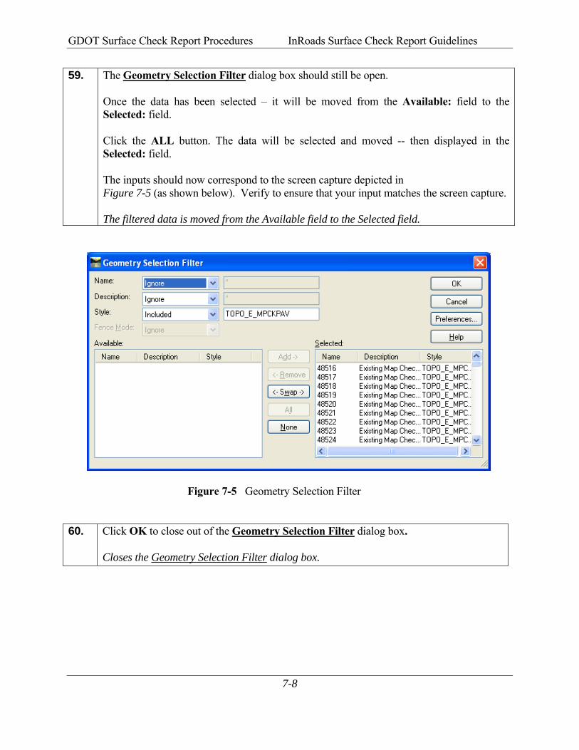
GDOT Surface Check Report Procedures InRoads Surface Check Report Guidelines
7-8
59. The Geometry Selection Filter dialog box should still be open. Once the data has been selected – it will be moved from the Available: field to the Selected: field. Click the ALL button. The data will be selected and moved -- then displayed in the Selected: field. The inputs should now correspond to the screen capture depicted in Figure 7-5 (as shown below). Verify to ensure that your input matches the screen capture. The filtered data is moved from the Available field to the Selected field.
Figure 7-5 Geometry Selection Filter
60. Click OK to close out of the Geometry Selection Filter dialog box.
Closes the Geometry Selection Filter dialog box.
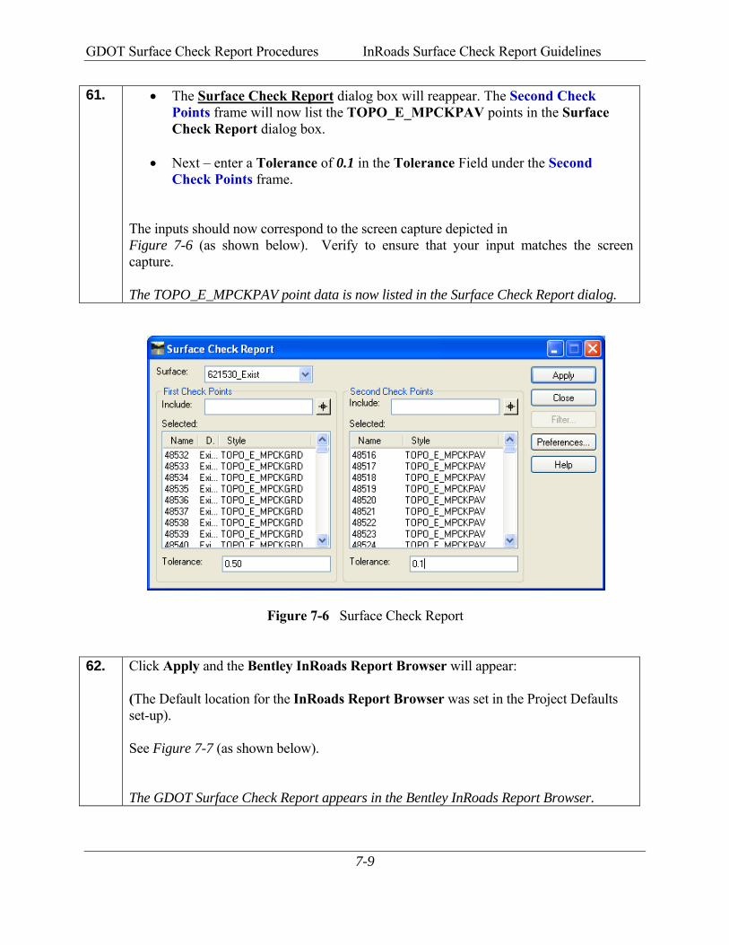
GDOT Surface Check Report Procedures InRoads Surface Check Report Guidelines
7-9
61. • The Surface Check Report dialog box will reappear. The Second Check Points frame will now list the TOPO_E_MPCKPAV points in the Surface Check Report dialog box.
• Next – enter a Tolerance of 0.1 in the Tolerance Field under the Second Check Points frame.
The inputs should now correspond to the screen capture depicted in Figure 7-6 (as shown below). Verify to ensure that your input matches the screen capture. The TOPO_E_MPCKPAV point data is now listed in the Surface Check Report dialog.
Figure 7-6 Surface Check Report
62. Click Apply and the Bentley InRoads Report Browser will appear:
(The Default location for the InRoads Report Browser was set in the Project Defaults set-up). See Figure 7-7 (as shown below). The GDOT Surface Check Report appears in the Bentley InRoads Report Browser.

GDOT Surface Check Report Procedures InRoads Surface Check Report Guidelines
7-10
Figure 7-7 Bentley InRoads Report Browser
63. Information Only: The Name of the Style Sheet is ‘GDOT Surface Check Report.xsl’ The Style Sheet should automatically appear because of the Project Defaults that were set up in the previous Chapters. If it does not automatically appear - click on the Style Sheet Name to select it. See Figure 7-7(as shown above). See Figure 7-8 (as shown below) for depiction of the Style Sheet. The GDOT Surface Check Report appears in the Bentley InRoads Report Browser.
Figure 7-8 GDOT Surface Check Report
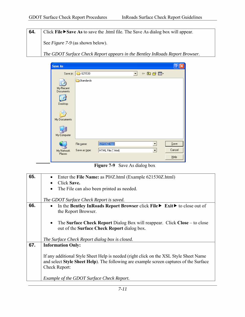
GDOT Surface Check Report Procedures InRoads Surface Check Report Guidelines
7-11
64. Click File Save As to save the .html file. The Save As dialog box will appear. See Figure 7-9 (as shown below). The GDOT Surface Check Report appears in the Bentley InRoads Report Browser.
Figure 7-9 Save As dialog box
65. • Enter the File Name: as PI#Z.html (Example 621530Z.html) • Click Save. • The File can also been printed as needed.
The GDOT Surface Check Report is saved.
66. • In the Bentley InRoads Report Browser click File Exit to close out of the Report Browser.
• The Surface Check Report Dialog Box will reappear. Click Close – to close out of the Surface Check Report dialog box.
The Surface Check Report dialog box is closed.
67. Information Only: If any additional Style Sheet Help is needed (right click on the XSL Style Sheet Name and select Style Sheet Help). The following are example screen captures of the Surface Check Report: Example of the GDOT Surface Check Report.
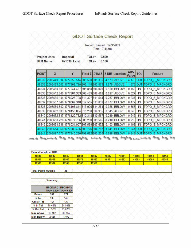
GDOT Surface Check Report Procedures InRoads Surface Check Report Guidelines
7-12

GDOT Surface Check Report Procedures InRoads Surface Check Report Guidelines
7-13
Appendix AOne Point On Chain Check
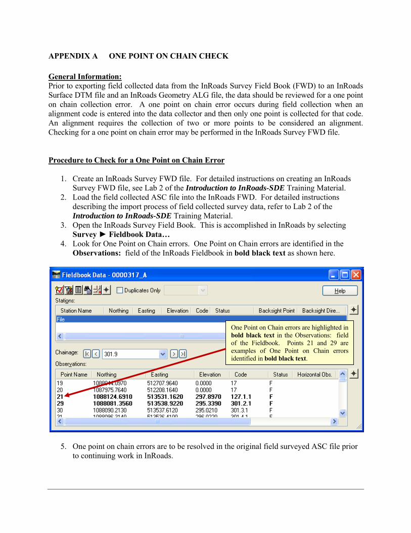
APPENDIX A ONE POINT ON CHAIN CHECK General Information: Prior to exporting field collected data from the InRoads Survey Field Book (FWD) to an InRoads Surface DTM file and an InRoads Geometry ALG file, the data should be reviewed for a one point on chain collection error. A one point on chain error occurs during field collection when an alignment code is entered into the data collector and then only one point is collected for that code. An alignment requires the collection of two or more points to be considered an alignment. Checking for a one point on chain error may be performed in the InRoads Survey FWD file. Procedure to Check for a One Point on Chain Error
1. Create an InRoads Survey FWD file. For detailed instructions on creating an InRoads Survey FWD file, see Lab 2 of the Introduction to InRoads-SDE Training Material.
2. Load the field collected ASC file into the InRoads FWD. For detailed instructions describing the import process of field collected survey data, refer to Lab 2 of the Introduction to InRoads-SDE Training Material.
3. Open the InRoads Survey Field Book. This is accomplished in InRoads by selecting Survey ► Fieldbook Data…
4. Look for One Point on Chain errors. One Point on Chain errors are identified in the Observations: field of the InRoads Fieldbook in bold black text as shown here.
5. One point on chain errors are to be resolved in the original field surveyed ASC file prior to continuing work in InRoads.
One Point on Chain errors are highlighted in bold black text in the Observations: field of the Fieldbook. Points 21 and 29 are examples of One Point on Chain errors identified in bold black text.
Appendix BSurface Check Report Style Sheet
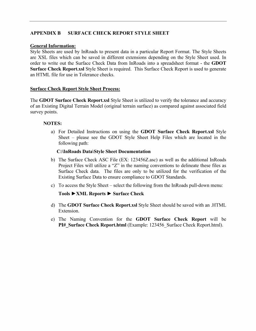
APPENDIX B SURFACE CHECK REPORT STYLE SHEET General Information: Style Sheets are used by InRoads to present data in a particular Report Format. The Style Sheets are XSL files which can be saved in different extensions depending on the Style Sheet used. In order to write out the Surface Check Data from InRoads into a spreadsheet format - the GDOT Surface Check Report.xsl Style Sheet is required. This Surface Check Report is used to generate an HTML file for use in Tolerance checks.
Surface Check Report Style Sheet Process:
The GDOT Surface Check Report.xsl Style Sheet is utilized to verify the tolerance and accuracy
of an Existing Digital Terrain Model (original terrain surface) as compared against associated field survey points.
NOTES: a) For Detailed Instructions on using the GDOT Surface Check Report.xsl Style
Sheet – please see the GDOT Style Sheet Help Files which are located in the following path:
C:\InRoads Data\Style Sheet Documentation b) The Surface Check ASC File (EX: 123456Z.asc) as well as the additional InRoads
Project Files will utilize a “Z” in the naming conventions to delineate these files as Surface Check data. The files are only to be utilized for the verification of the Existing Surface Data to ensure compliance to GDOT Standards.
c) To access the Style Sheet – select the following from the InRoads pull-down menu:
Tools ►XML Reports ► Surface Check
d) The GDOT Surface Check Report.xsl Style Sheet should be saved with an .HTML Extension.
e) The Naming Convention for the GDOT Surface Check Report will be PI#_Surface Check Report.html (Example: 123456_Surface Check Report.html).