Surepowr Series Sure 65 - Dresser Utility Solutions
20
Surepowr Series Sure 65 Installation, Operation and Maintenance Manual Table of Contents 1. Actuator Use .................................................................... 2 Intended Use for Actuator .............................................................2 Actuator Range of Application.....................................................2 2. Actuator Ratings ............................................................. 3 Ratings ..................................................................................................3 3. Safety ............................................................................... 4 Safety First! ..........................................................................................4 Warnings and Notices .....................................................................4 Joint Handling ....................................................................................4 Fasteners ..............................................................................................5 Seals .......................................................................................................6 Cable Glands .......................................................................................6 Grounding and Bonding ................................................................6 4. Installation ...................................................................... 7 Outline Dimensions .........................................................................8 Cover Removal and Assembly ......................................................9 Mounting .............................................................................................9 Mounting Fastener Specification ................................................9 Horizontal Mounting .......................................................................9 Conduit Locations and Thread Sizes ....................................... 10 Cable Glands .................................................................................... 10 Grounding and Bonding ............................................................. 10 Wiring ................................................................................................. 11 Setting Mechanical Travel Stops ............................................... 12 Limit Switch Settings .................................................................... 13 Switch adjustments for clockwise spring return operation ............................................................... 13 Switch adjustments for counter-clockwise spring return operation ............................................................... 15 5. Operation ...................................................................... 15 Thermal Overload .......................................................................... 15 Duty Cycle ......................................................................................... 16 6. Maintenance ................................................................. 17 Mounting Fasteners ...................................................................... 17 Enclosure Cover Screws ............................................................... 17 Seals and Cable Glands ................................................................ 17 7. Storage .......................................................................... 18 8. Troubleshooting ........................................................... 19 Problem 1: Actuator is receiving electric power but the motor does not respond.............................................. 19 Problem 2: Actuator is receiving electric power but the motor only hums. ........................................................... 19 Problem 3: Actuator runs but operation is erratic.............. 19 Problem 4: Motor runs continuously in spring return direction after actuator output shaft stops rotating. ........ 19 Locating and Ordering Parts ...................................................... 19 RCS Actuators
Transcript of Surepowr Series Sure 65 - Dresser Utility Solutions
Surepowr Series Sure 65Installation, Operation and Maintenance Manual
Table of Contents1. Actuator Use ....................................................................2
Intended Use for Actuator .............................................................2
Actuator Range of Application .....................................................2
2. Actuator Ratings .............................................................3
Ratings ..................................................................................................3
3. Safety ...............................................................................4
Safety First! ..........................................................................................4
Warnings and Notices .....................................................................4
Joint Handling ....................................................................................4
Fasteners ..............................................................................................5
Seals .......................................................................................................6
Cable Glands .......................................................................................6
Grounding and Bonding ................................................................6
4. Installation ......................................................................7
Outline Dimensions .........................................................................8
Cover Removal and Assembly ......................................................9
Mounting .............................................................................................9
Mounting Fastener Specification ................................................9
Horizontal Mounting .......................................................................9
Conduit Locations and Thread Sizes ....................................... 10
Cable Glands .................................................................................... 10
Grounding and Bonding ............................................................. 10
Wiring ................................................................................................. 11
Setting Mechanical Travel Stops ............................................... 12
Limit Switch Settings .................................................................... 13
Switch adjustments for clockwise spring return operation ............................................................... 13
Switch adjustments for counter-clockwise spring return operation ............................................................... 15
5. Operation ......................................................................15
Thermal Overload .......................................................................... 15
Duty Cycle ......................................................................................... 16
6. Maintenance .................................................................17
Mounting Fasteners ...................................................................... 17
Enclosure Cover Screws ............................................................... 17
Seals and Cable Glands ................................................................ 17
7. Storage ..........................................................................18
8. Troubleshooting ...........................................................19
Problem 1: Actuator is receiving electric power but the motor does not respond. ............................................. 19
Problem 2: Actuator is receiving electric power but the motor only hums. ........................................................... 19
Problem 3: Actuator runs but operation is erratic. ............. 19
Problem 4: Motor runs continuously in spring return direction after actuator output shaft stops rotating. ........ 19
Locating and Ordering Parts ...................................................... 19
RCS Actuators
2 | Dresser Natural Gas Solutions
This manual gives instructions for storing, installing, operating and servicing the RCS Surepowr* Series Sure 65 electromechanical actuator. Refer all questions not covered in this manual to:
Check the compatibility of the actuator’s nameplate markings with the classification of the installation area’s environment and its ambient and admissible surface temperatures.
Only qualified, certified and properly trained personnel shall conduct actuator installation and maintenance.
1. Actuator Use
Industrial Products GroupRCS Actuators16240 Port Northwest DriveHouston, TX 77041T: 832-590-2306Toll Free: 1-800-945-9898F: 713-849-2879
WARNING
PPE
Approved Personal Protection Equipment for the site must
be worn.
ATTENTION
EPI
Un équipement de protection personnelle approuvé pour le site
doit être porté.
RCS Sure 65 IOM Manual. NGS.IPG.0037b | 3
Certification North America:Class I, Group C and D, Class II, Group E, F and G, Class III
Ex d IIB Gb, Ex tb IIIC T85 Db IP 66/67;
Class I, Zone 1, AEx d IIB. Zone 21, AEx tD, T85
Enclosure Types 4/4X & 6; Ambient Rating: -40°C to +65°C
APPLICABLE STANDARDS:
2. Actuator Ratings
C22.2 No. 0-10 CAN/CSA-C22.2 No. 60529:16C22.2 No. 25-1966 UL 50, 12th Ed.C22.2 No. 30-M1986 UL 50E, 2nd Ed.C22.2 No. 94.1-07 UL 429, 7th Ed.C22.2 No. 94.2, 2nd Ed. UL 1203, 5th Ed.C22.2 No. 139-13 UL 60079-0, 6th Ed.CAN/CSA-C22.2 No. 60079-0:2015 UL 60079-1, 7th Ed.CAN/CSA-C22.2 No. 60079-1:2016 UL 60079-31, 2nd Ed.CAN/CSA-C22.2 No. 60079-31:2015 ANSI/IEC 60529 (2004)
Model
Input Volt-age 1-Phase,
50/60 Hz.
Output Torque Electrical Speed of
Operation 90° Revolution
Spring Speed of Operation 90° Revolution~
Duty Cycle Rating ** (22.5° C)
Current Rating
N.L.A. F.L.A. L.R.A.
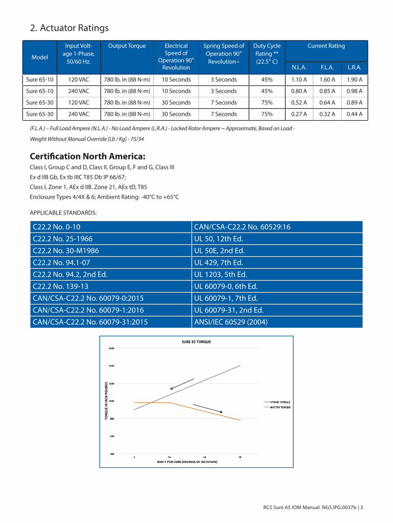
Sure 65-10 120 VAC 780 lb. in (88 N-m) 10 Seconds 3 Seconds 45% 1.10 A 1.60 A 1.90 A
Sure 65-10 240 VAC 780 lb. in (88 N-m) 10 Seconds 3 Seconds 45% 0.80 A 0.85 A 0.98 A
Sure 65-30 120 VAC 780 lb. in (88 N-m) 30 Seconds 7 Seconds 75% 0.52 A 0.64 A 0.89 A
Sure 65-30 240 VAC 780 lb. in (88 N-m) 30 Seconds 7 Seconds 75% 0.27 A 0.32 A 0.44 A
(F.L.A.) – Full Load Ampere (N.L.A.) - No Load Ampere (L.R.A.) - Locked Rotor Ampere ~ Approximate, Based on Load -
Weight Without Manual Override [Lb / Kg] - 75/34

4 | Dresser Natural Gas Solutions
3. Safety
Safety First!In the maintenance and operation of mechanical equipment, safety must be considered at all times. Through the use of the proper clothes, tools, and methods of handling, serious accidents can be prevented.
A number of safety precautions are listed throughout this manual. Study them carefully and follow them, and insist that those working for and with you do the same. Remember, an accident is usually caused by carelessness, neglect, or oversight.
Warnings and NoticesPictograms are used throughout this manual to denote important or dangerous situations. If warnings are not respected, dangerous situations may result that may cause serious personal injury or death. Examples of the pictograms throughout this manual:
WARNING
GROUNDING LUG:
Unit must be grounded with minimum size
10 AWG wire.
ATTENTION
COSSE DE MISE À LA TERRE :
l'appareil doit être mis à la terre à l'aide d'un fil d'un calibre minimal
de 10 AWG.
WARNING
Indicates a hazardous situation that, if not avoided, could result in death or serious injury.
AVERTISSEMENT
Indique une situation dangereuse qui, si elle n'est pas évitée, pour-rait entraîner la mort ou des blessures graves.
WARNING
ELECTRICAL SHOCK WARNING:
Indicates a risk of death or serious injury due to electrical shock if
safety measures are not adhered to.
ATTENTION
AVERTISSEMENT DE CHOC ÉLECTRIQUE :
indique un risque de mort ou de blessure grave par électrocution si les mesures de sécurité ne sont
pas respectées.
NOTICE
Indicates practices not related to personal injury, but addresses important information regarding the installation,
operation or maintenance of the unit.
NOTIFICATION
indique les pratiques qui ne sont pas liées à des blessures corpo-relles, mais aborde des informations importantes concernant le
montage, l'exploitation ou la maintenance de l'appareil.
CAUTION
Indicates a potentially hazardous situation that, if not avoided, can result in minor to moderate injury, or serious damage to the product. The situation described in the CAUTION may, if not avoided, lead to
serious results. Important safety measures are described in CAUTION (as well as WARNING), so be sure to observe them.
PRÉCAUTION
indique une situation potentiellement dangereuse qui, si elle n'est pas évitée, peut entrainer des blessures mineures ou modérées ou de graves dommages matériels. La situation décrite sous le titre ATTEN-TION peut, si elle n'est pas évitée, dégénérer avec des conséquences
graves. Les mesures de sécurité importantes sont décrites sous le titre ATTENTION (et sous le titre AVERTISSEMENT), par conséquent, il est
impératif de les observer.
Observe these and all other warnings at all times during installation, operation and maintenance of this product:
WARNING
EXPLOSION HAZARD
Death or serious injury could result.
Do not open unless power to actuator has been disconnected.
ATTENTION
RISQUE D'EXPLOSION
Peut entraîner la mort ou de graves blessures.
Ne pas ouvrir à moins que l'actionneur ne soit mis hors ten-
sion.

RCS Sure 65 IOM Manual. NGS.IPG.0037b | 5
WARNING
EXPLOSION HAZARD
Death or serious injury could result.
Do not open if an explosive atmo-sphere may be present.
ATTENTION
RISQUE D'EXPLOSION
Peut entraîner la mort ou de graves blessures.
Ne pas ouvrir en présence d'une atmosphère potentiellement
explosive.
WARNING
ELECTRICAL SHOCK WARNING:
Indicates a risk of death or serious injury due to electrical shock if
safety measures are not adhered to.
ATTENTION
AVERTISSEMENT DE CHOC ÉLECTRIQUE :
indique un risque de mort ou de blessure grave par électrocution si les mesures de sécurité ne sont
pas respectées.
WARNING
HIGH ENERGY HAZARD
Death or serious injury could result.
Do not attempt to repair actuator unless properly trained in specific
repair methods for this device.
ATTENTION
RISQUE D'ÉNERGIE ÉLEVÉE
Peut entraîner la mort ou de graves blessures.
Ne pas tenter de réparer l'actionneur à moins d'être bien formé aux méthodes de répara-
tion spécifiques pour cet appareil.
Joint Handling
Do not open actuator cover if there is risk of an explosive environment. Care must be taken with the joint surface when handling, installing or storing to preserve the integrity of the explosion-proof joint. See joint handling instructions under the Installation section of this manual. Failure to observe these instructions may compromise the enclosure protection rating.
FastenersBoth Metric and Imperial fasteners are used, use applicable tools. The enclosure cover bolts and the hard stop assemblies are metric threads and the rest are imperial threads.
All fasteners must be installed and properly tightened. Enclosure cover screws, mounting fasteners and cable glands must be tightened to specified torque values. Failure to maintain specified torque for cover screws and cable glands may compromise the enclosure protection rating. Failure to maintain specified torque for mounting fasteners may compromise actuator operation. See Installation and Maintenance sections of this manual for specified fastener and torque requirements, as well as safety and maintenance information.

6 | Dresser Natural Gas Solutions
WARNING
EXPLOSION HAZARD
Death or serious injury could result.
Maintain cover screw and cable gland fastener torque specifica-
tions to ensure enclosure protec-tion.
ATTENTION
RISQUE D'EXPLOSION
Peut entraîner la mort ou de graves blessures.
Veuillez respecter les spécifica-tions de couple de serrage de la
vis du couvercle et du presse-étoupe afin d'assurer la protec-
tion de l'enceinte.
LiftingLifting Lug holes are available in Sure 65. Special care must be given during handling and lifting of both Sure 65.
WARNING
LIFTING HAZARD
May result in injury.
See safety manual for lifting instructions.
ATTENTION
RISQUE LIÉ AU LEVAGE
Peut entraîner des blessures.
Voir le manuel de sécurité pour les instructions de levage.
SealsAll seals must be routinely checked to ensure that they are in good condition, properly sealed and replaced as needed. Failure to do so may compromise the enclosure protection rating. See Installation and Maintenance sections for instructions.
WARNING
EXPLOSION HAZARD
Death or serious injury could result.
Maintain all seals to ensure enclo-sure protection.
ATTENTION
RISQUE D'EXPLOSION
Peut entraîner la mort ou de graves blessures.
Veillez à l'étanchéité des joints afin d'assurer la protection de
l'enceinte.
Cable GlandsCable glands must be installed and maintained and properly torqued according to the Installation and Maintenance specifications. Failure to do so may compromise the enclosure protection rating. See Installation and Maintenance sections for instructions.
WARNING
EXPLOSION HAZARD
Death or serious injury could result.
Maintain cable gland torque specifications to ensure enclosure
protection.
ATTENTION
RISQUE D'EXPLOSION
Peut entraîner la mort ou de graves blessures.
Veuillez respecter les spécifica-tions de couple du presse-étoupe
afin d'assurer la protection de l'enceinte.
Grounding and BondingFailure to properly ground or bond the device may result in death or serious injury due to explosive hazards. See Bonding and Grounding under the Installation section of this manual for proper specifications.
WARNING
EXPLOSION HAZARD
Death or serious injury could result.
Ensure device is properly grounded to
avoid explosion hazard.
ATTENTION
RISQUE D'EXPLOSION
Peut entraîner la mort ou de graves blessures.
Assurez-vous de la bonne mise à la terre du dispositif afin d'éviter
tout risque d'explosion.
Spring Housing
CAUTION
Loaded spring inside actuator. Do not attempt to repair actuator below top gear plate,
unless properly trained on repair methods.
ATTENTION
ressort à l'intérieur de l'actionneur. Ne pas essayer de réparer l'actionneur en dessous de la plaque
supérieure de vitesse, à moins d'être bien formé sur les méthodes de réparation.

RCS Sure 65 IOM Manual. NGS.IPG.0037b | 7
4. Installation
WARNING
HIGH ENERGY HAZARD – LOADED SPRING
Death or serious injury could result.
Do not attempt to repair actuator unless properly trained in specific
repair methods for this device.
ATTENTION
RISQUE D'ÉNERGIE ÉLEVÉE - À RESSORT
Peut entraîner la mort ou de graves blessures.
Ne pas tenter de réparer l'actionneur à moins d'être bien formé aux méthodes de répara-
tion spécifiques pour cet appareil.
NOTICE
SurePowr actuators can be supplied for clockwise or counter-clockwise spring-driven rotation
(viewed from the top of the actuator). The spring drive rotation is noted on the actuator name tag and wiring diagram.
Ensure that the actuator has been supplied with the proper spring drive operation for the application prior
to installation on the driven device.
NOTIFICATION
les actionneurs SurePowr peuvent être fournis pour une rotation par ressort dans le sens horaire ou anti-horaire (vue du haut de
l'actionneur). La rotation de l'entraînement à ressort est indiquée sur l'étiquette
du nom de l'actionneur ainsi que sur le schéma de câblage. Assurez-vous que l'opération d'entraînement à ressort de
l'actionneur qui vous a été fourni soit appropriée avant de la monter sur le dispositif entraîné.

8 | Dresser Natural Gas Solutions
ALL DIMENSIONS ARE IN INCHES [MM]Actuator Outline Dimensions
A
VIEWSCALE 1 : 16
4X 3/8-16 UNC - 2B .60[15.2]ON 4.016 [102] B.C.
2.84072.12
2X .8722.06
2.25057.15
1.94949.50
CONDUIT ENTRY
SURE 65 OUTPUT DRIVE F10INCH[MM]
HOLES MARKED "X" FOR F10 MOUNTHOLES MARKED "Y" FOR F07 MOUNT
HOLES MARKED "Z" FOR SURE 49 MOUNTING
Z
Z
Z
Z
X
XX
X
Y
Y
Y
Y
4X 5/16-18 UNC-2B .63[16.0]ON 2.76 [70.1] B.C
4X 5/16-18 UNC - 2B .63[16.0]ON 3.18 [80.8] B.C

RCS Sure 65 IOM Manual. NGS.IPG.0037b | 9
Cover Removal and Assembly
WARNING
Explosion Hazard – Remove Power
Death or Serious Injury could result.
Do not open unless power to actuator has been disconnected.
WARNING
Explosive Atmosphere HazardDeath or Serious Injury could result.
Do not open if an explosive atmosphere may be present.
WARNING
Explosion HazardDeath or Serious Injury could result.
After De-energizing, delay X minutes before opening.
WARNING
Explosion HazardDeath or Serious injury could result.
Maintain Cover Screw torque specifications to avoid hazard.
Do not store or set actuator cover with the flange surface down. To preserve the explosion-proof integrity of the joint, care must be taken not to damage, scuff or score the flange joint surfaces and associated parts (cable glands, joints, etc.). Take care not to damage the cover joint when removing or installing the cover. Ensure that the joint is clean and free of debris or damage and ensure that O-ring is intact and in place before replacing cover. The explosion-proof joint may be lubricated with an appropriate, non-corrosive, non-hardening grease, such as petroleum jelly.
When replacing the actuator cover, ensure the 8 Cover Screws are tightened to specified torque value and that all screws are intact. Failure to maintain specified screw torque may compromise the enclosure protection rating.
Enclosure Cover Screw Specifications:Eight 10 X 1.5 X 35mm long, Grade A2-70 Stainless Steel, torqued to 25 Ft-Lbs [34 N-m]
Mounting
WARNING
High Energy Hazard – Loaded Spring
Death or Serious Injury could result.
Do not attempt to un-mount the Actuator while under load.
The actuator is shipped in the power off spring return position. Ensure that the driven device is orientated to its spring return position prior to installation of the actuator.
Care should be taken to maintain proper alignment between the actuator and the device shaft. The actuator should install on the shaft without binding. The mounting face should be centered on the bracket without binding or side load.
Mount the actuator to the device. Ensure the actuator is centered properly on the device shaft, and then tighten all fasteners evenly.
Mounting Fastener Specification
Minimum four, 5/16”-18 UNC, Grade 8 or equivalent, torqued to 23Ft-Lb (31 N-m)
Horizontal Mounting
The Actuator is suitable for mounting in any orientation; however, for horizontal mounting, additional support is recommended and to be attached at the Lifting Lug screw holes.

10 | Dresser Natural Gas Solutions
Conduit Locations and Thread Sizes
The actuator is supplied with two - ¾” NPT conduit entries.
Refer to the Sure50/75 outline drawing for conduit entry locations. One Metal Plug and Other plastic plug for only shipping purpose.
Cable Glands
Ensure that the cable glands and wiring conform to the applicable Explosion-Proof Equipment Standards and to the Explosion-Proof Classification.
If an adapter is necessary to fit a cable gland, only one adapter is allowed at cable entry.
If one of the cable entries is not used, it should be sealed with a certified metal plug, without an adapter.
Cable glands should be fastened firmly to prevent ingress of water or dirt and should be tightened to the manufacturer’s specified torque to ensure the required enclosure protection.
Grounding and Bonding
The internal and external grounding points are electrically connected within the actuator. The Internal Grounding Point is a green Grounding Screw located on the surface of the top gear plate near the conduit entry. The External Grounding Point location is below the conduit entries and tightened with a 3/32” hex key wrench.
Grounding Lug
Plug is only for
shipping purposes

RCS Sure 65 IOM Manual. NGS.IPG.0037b | 11
WARNING
HIGH ENERGY HAZARD – LOADED SPRING
Death or serious injury could result.
Do not attempt to repair actuator unless properly trained in specific
repair methods for this device.
ATTENTION
RISQUE D'ÉNERGIE ÉLEVÉE - À RESSORT
Peut entraîner la mort ou de graves blessures.
Ne pas tenter de réparer l'actionneur à moins d'être bien formé aux méthodes de répara-
tion spécifiques pour cet appareil.
Wiring
Wiring diagrams vary according to specific product configuration. Refer to the wiring diagram supplied with the actuator for field wiring connections.
WARNING
EXPLOSION HAZARD
Death or serious injury could result.
Maintain cover screw torque specifications to ensure enclosure
protection.
ATTENTION
RISQUE D'EXPLOSION
Peut entraîner la mort ou de graves blessures.
Veuillez respecter les spécifica-tions de couple de la vis du cou-vercle afin d'assurer la protection
de l'enceinte.
Plug is only for
shipping purposes
NOTICE
Use a minimum of #18 AWG stranded wire.
NOTIFICATION
utiliser un fil torsadé d'un calibre minimal de #18 AWG.
NOTICE
Units should be connected using the wiring diagram supplied with the actuator.
NOTIFICATION
les dispositifs doivent être raccordés en utilisant le schéma de câblage fourni avec l'actionneur.
NOTICE:
Direction of rotation is based on viewing the actuator from the top.
NOTIFICATION
sens de rotation vue du haut de l'actionneur.
NOTICE
To operate multiple actuators in parallel from a single source requires isolating relays in the field wiring.
NOTIFICATION
les relais dans le câblage doivent être isolés afin de faire fonctionner plusieurs actionneurs en parallèle à partir d'une source unique.

12 | Dresser Natural Gas Solutions
Setting Mechanical Travel Stops
NOTICE
Only the spring returnl End Travel Stop may be adjusted mechanically. The total adjustment available is +/- 5°.
To adjust the spring return end position, perform the following:
• Back off Jam Nut on spring return end travel stop.
• Rotate travel stop adjustment screw inward or outward to adjust the spring return end position.
• Hold the adjustment screw from turning and re-tighten Jam Nut in order to lock this adjustment screw in place and maintain enclosure rating.
NOTICE
Do not loosen the large hex screw in the travel stop assembly, this will result in spring release and will remove the spring
pre-load.
NOTICE
After adjusting the travel stop, actuator spring return end limit switches must be readjusted.
Jam Nut
Travel Stop Adjustment Screw
Do Not Loosen
Do Not Loosen
Clock-Wise Spring Return Version(Counter Clock-Wise orientation will be seen as a mirror image)
• Readjust the spring return cam as necessary

RCS Sure 65 IOM Manual. NGS.IPG.0037b | 13
Limit Switch Settings
WARNING
EXPLOSION HAZARD
Death or serious injury may result.
Switches must stop motor.
ATTENTION
RISQUE D'EXPLOSION
Peut entraîner la mort ou de graves blessures.
Les commutateurs doivent arrêter le moteur.
Switch 4
(CCW Auxiliary switch)
Cam Setscrew Locations
Cam 4
Cam 2
Cam 3
Cam 1
Switch 3
(CW Auxiliary switch)
Switch 2
(Counter-CW motor stop)
Switch 1
(Clockwise motor stop)
Switch adjustments for clockwise spring return operation
Cam 1 actuates the clockwise motor stop switch.
Cam 2 actuates the counter-clockwise motor stop switch.
Cams 3 and 4 actuate the auxiliary switches.
Setting the clockwise (spring return position) switch:
1. Ensure actuator is positioned in the clockwise (spring return) position. Ensure the end of travel stop is properly adjusted (see Setting Mechanical Travel Stops section).
2. Loosen the two setscrews on Cam 1 (1/16” hex drive). Rotate Cam 1 counter-clockwise away from its switch until it clears the switch lever
3. Rotate Cam 1 CW until it contacts the switch lever and the switch “breaks” – a slight “click” can be heard. Continue to rotate the cam slightly in the clockwise direction; this ensures that the motor will be switched off before the actuator reaches its end of travel stop. An ohmmeter might have to be used in some cases.
4. Retighten both set screws in the cam.
NOTICE
Spring Return end limit switch should trip well before the actuator drives into the mechanical travel stop. Failure to
properly set the limit switch will result in continuous motor operation after driving into the mechanical travel stop.

14 | Dresser Natural Gas Solutions
Setting the counter-clockwise (motor drive position) switch:
1. With actuator in its full counter-clockwise position, loosen set screws on Cam 2 and rotate the Cam CW until it clears the switch lever.
2. Rotate the cam CCW until it contacts the switch lever and the switch “breaks” A slight click can be heard. An ohmmeter might have to be used in some cases.
3. Retighten both set screws in the cam.
Auxiliary Switches:
Set Cams 3 and 4 to trip auxiliary switches as required for the application. If used for end of travel indication they should be sit to trip before the corresponding end of travel switch.
NOTICE
Replace Cover and Cover Screws in accordance with the specifications stated in the Installation Section of this manual.
Switch adjustments for counter-clockwise spring return operation
Cam 1 actuates the clockwise motor stop switch.
Cam 2 actuates the counter-clockwise motor stop switch.
Cams 3 and 4 actuate the auxiliary switches.
Setting the counter clockwise (spring return position) switch:
1. Ensure actuator is positioned in the counter clockwise spring return position. Ensure the end of travel stop is properly adjusted (see Setting Mechanical Travel Stops section). Loosen the two setscrews on Cam 2 (1/16” hex drive). Rotate Cam 2 clockwise away from its switch until it clears the switch lever.
2. Rotate the Cam 2 CCW until it contacts the switch lever and the switch “breaks” – a slight “click” can be heard. Continue to rotate the cam slightly in the counter clockwise direction; this ensures that the motor will be switched off before the actuator reaches its end of travel stop. Tighten both set-screws on Cam 2. An ohmmeter might have to be used in some cases.
3. Retighten both set screws in the cam.
NOTICE
Spring return end limit switch should trip well before the actuator drives into the mechanical travel stop. Failure to
properly set the limit switch will result in continuous motor operation after driving into the mechanical travel stop.
Setting the clockwise (motor drive position) switch:
1. With actuator in its full clockwise position, loosen set screws on Cam 1 and rotate the cam CW until it clears the switch lever.
2. Rotate the cam CCW until it contacts the switch lever and the switch “breaks” A slight click can be heard. An ohmmeter might have to be used in some cases.
3. Retighten both set screws in the cam.
Auxiliary Switches:
Set Cams 3 and 4 to trip auxiliary switches as required for the application. If used for end of travel indication they should be sit to trip before the corresponding end of travel switch.
NOTICE
Replace Cover and Cover Screws in accordance with the specifications stated in the Installation Section of this manual.

RCS Sure 65 IOM Manual. NGS.IPG.0037b | 15
5. OperationPower On: The electric motor drives the gear train, which in turn winds the spring and turns the device. An internal limit switch de-energizes the motor and energizes the brake which holds the return spring and device in position.
Power Loss: When the current is interrupted by either a control signal or a power failure, the return spring drives the device to its original position.
NOTICE
It is recommended that the actuator be driven electrically in both directions for normal operation to prolong unit life.
Thermal Overload
The internal thermal overload switch de-energizes the motor and prevents overheating of the motor windings due to excessive operation, stalling or high ambient temperatures. De-energizing the motor due to thermal overload will result in actuator spring-driving to the power loss position.

16 | Dresser Natural Gas Solutions
Sure 65 Duty Cycle Ratings
** 120VAC Actuators Certified Duty Cycle Rating is -40°C To +40°C is 25% and +40°C to +65°C is 20% per UL429, 7th Ed., Clause 27
** 240VAC Actuators Certified Duty Cycle Rating is -40°C To +40°C is 30% and +40°C to +65°C is 20% per UL429, 7th Ed., Clause 27

RCS Sure 65 IOM Manual. NGS.IPG.0037b | 17
6. MaintenanceOnly qualified, certified and properly trained personnel shall conduct actuator maintenance.
The gear train is permanently lubricated at the factory for the average life of the actuator. No further attention is required.
Commissioned actuators should be checked routinely for damage to paint finish and touch-up paint applied where necessary to prevent corrosion.
Actuators which are infrequently operated should be tested every 6 months to ensure that it is ready to operate.
Mounting Fasteners
For Mounting Fastener Specifications, refer to the Installation section of this manual.
Six months after commissioning, and annually thereafter, check fasteners between the actuator and the driven device for tightness. If required, tighten fasteners being sure to apply the correct specified torque. Failure to maintain specified torque may compromise actuator operation.
Enclosure Cover Screws
For Enclosure Cover Screw Specifications and torque, refer to the Installation section of this manual.
Six months after commissioning, and annually thereafter, check the actuator Cover screws for tightness. If required, tighten screws applying the correct specified torque. Failure to maintain specified screw torque may compromise the enclosure protection rating.
The explosion-proof joint may be lubricated with an appropriate, non-corrosive, non-hardening grease, such as petroleum jelly.
Seals and Cable Glands
Elastomer-based seals may degrade as they age; the seals must be regularly checked and replaced as needed. When replacing seals, be sure the sealing surfaces are clean.
O-rings should be checked regularly to ensure that they are in good condition. Ensure that O-rings are in good condition, placed correctly and that the sealing faces are clean. You may apply a thin film of non-acidic grease, such as petroleum jelly, to the sealing faces.
Cable glands should be checked regularly to ensure they are tightened according to specifications to prevent ingress of water or dirt. Routinely check that cable glands are tightened to the manufacturer’s specified torque to ensure the required enclosure protection.
WARNING
HIGH ENERGY HAZARD – LOADED SPRING
Death or serious injury could result.
Do not attempt to repair actuator unless properly trained in specific
repair methods for this device.
ATTENTION
RISQUE D'ÉNERGIE ÉLEVÉE - À RESSORT
Peut entraîner la mort ou de graves blessures.
Ne pas tenter de réparer l'actionneur à moins d'être bien formé aux méthodes de répara-
tion spécifiques pour cet appareil.
WARNING
EXPLOSION HAZARD
Death or serious injury may result.
Switches must stop motor.
ATTENTION
RISQUE D'EXPLOSION
Peut entraîner la mort ou de graves blessures.
Les commutateurs doivent arrêter le moteur.
18 | Dresser Natural Gas Solutions
7. StorageThe Surepowr actuator must be stored in a clean, dry, temperature controlled building which is protected from the weather. Precautions shall be taken to prevent condensation inside or outside the actuator. If there is insufficient temperature and humidity control, the internal heaters must be energized to protect the unit against condensation from extreme temperature variations. The actuators shall be stored off the floor on suitable pallets and must be covered with an unsealed dust protector allowing side and bottom ventilation. Conduit entries must be sealed with the shipping plugs provided or other suitable means. The control cover is to be installed tightly.

RCS Sure 65 IOM Manual. NGS.IPG.0037b | 19
8. Troubleshooting
NOTICE
Most actuator problems occur due to incorrect cam/travel limit switch setting or the incorrect setting of an external travel stop
on the device that the actuator is operating.
Problem 1: Actuator is receiving electric power but the motor does not respond.
• Check actuator nameplate to insure correct model, voltage and spring return direction.
• Check field wiring against the wiring diagram provided with the actuator.
• Check travel limit switch cam settings per Installation Section in this manual.
Problem 2: Actuator is receiving electric power but the motor only hums.
• Check actuator nameplate to insure correct model, voltage and spring return direction.
• Check field wiring against the wiring diagram provided with the actuator.
• Check travel limit switch cam settings per Installation Section in this manual.
• Check to insure the motor brake is completely disengaged when power is applied to the motor.
• Ensure that actuator is not stalled which could be due to any of the following reasons:
– Incorrect travel limit switch settings resulting in actuator stalling against device being driven.
– Incorrect travel stop settings on device being actuated.
– Overloading the actuator with a torque above the rating. See Rating Section in this manual.
• Confirm that the orientation of the driven device matches the actuator shaft. When not powered, Sure Powr actuators will be in their spring return position, either fully CW or fully CCW depending on the model. The shaft of the driven device must be in the same orientation when the actuator is being installed.
Problem 3: Actuator runs but operation is erratic.
• Check actuator nameplate to insure correct model, voltage and spring return direction.
• Check field wiring against the wiring diagram provided with the actuator.
• Check travel limit switch cam settings per Installation Section in this manual.
• Check ambient temperature. Standard Surepowr actuators have a maximum ambient operating temperature rating of -40°C to +65°C.
• Check duty cycle (frequency of operation). See Operation Section in this manual.
• Ensure that actuator is not stalled which could be due to any of the following reasons:
– Incorrect travel limit switch settings resulting in actuator stalling against device being driven.
– Incorrect travel stop settings on device being actuated.
– Overloading the actuator with a torque above the rating. See Rating Section in this manual.
Problem 4: Motor runs continuously in spring return direction after actuator output shaft stops rotating.
• Adjust spring return side travel limit switch so that the cam trips the switch well before the shaft stops motion.
NOTICE
Standard Surepowr actuators are manufactured with thermal over- load protectors in series with the motor common. Should any of the above problems cause the protector
to open, it will automatically reset when the motor temperature drops to a safe level.
Locating and Ordering Parts
For ease and accuracy in identifying and ordering spare or replacement parts, submit the following information from unit nameplate:
1. Serial Number
2. Voltage
3. Spring return direction (CW or CCW)

Industrial Products GroupRCS Actuators16240 Port Northwest DriveHouston, TX 77041T: 832-590-2306Toll Free: 1-800-945-9898F: 713-849-2879
© 2018 Natural Gas Solutions North America, LLC – All rights reserved. Natural Gas Solutions reserves the right to make changes in specifications and features shown herein, or discontinue the product described at any time without notice or obligation. Contact your Dresser Natural Gas Solutions representative for the most current information. The Dresser Logo and all Trademarks containing the term “Dresser” are the property of Dresser, LLC, a subsidiary of Baker Hughes, a GE Company. www.dresserngs.com
RCS Sure 50 & 75 IOM Manual NGS.IPG.0037b
7.19


![Free Dresser[1]](https://static.fdocuments.in/doc/165x107/577d35a91a28ab3a6b910d4e/free-dresser1.jpg)