Sure-Seal - Farnell
16
Sure-Seal ▲ ® Specifications subject to change; see inside back cover. 1 For technical assistance, price or delivery info. call 1-800-523-0727 or visit www .suresealconnections .com Low cost, high reliability Sure-Seal Applications Features Wet, humid, or dirty environments requiring a low cost, small and reliable sealed connector • Automotive • Trucks and Buses • Marine • Off-road Vehicles • Appliances • Industrial Machinery • Low Voltage Lighting Systems Low Installed Cost One piece molded bodies and crimp contacts provide a low cost solution. In addition, these connectors can be easily terminated by the user. Water Submersible Not just splash-proof, but truly submersible for short periods of time. Sure-Seal ® will seal to the requirements of IP67 and DIN 400 50. Resistant to Automotive/Industrial Environments Sure-Seal ® will operate in temperatures from - 40˚F to +221˚F under conditions of high humidity, severe vibration, ice and mud. Sealing integrity is maintained with exposure to brake fluid, gasoline, diesel fuel, anti- freeze, ultraviolet, ozone, and steam. Wide Range of Wire Gauges and Current Carrying Capability Up to 85 amps with wire gauges from size 20 up to size 4 AWG wire. One-Piece Connector Sure-Seal ® has a simple one-piece molded body. No other parts (other than contacts) are required. Bodies mate using multiple resilient seals and will remain mated even under severe vibration and shock. Field Serviceable The use of removable crimp contacts allows Sure-Seal ® connections to be changed or modified in the field if necessary. Polarized Against Mis-mates Connector halves use both pin and socket contacts. The plug and receptacle must be properly oriented for the connectors to mate. Raised indexing ribs in conjunction with a stepped plane allow blind mating of the connector halves even in dark or cramped spaces. Three Sure-Seal ® Versions Sure-Seal ® is available in three versions. The basic Sure-Seal ® line is the broadest and ideal for most applications. Mini-Sure-Seal ® provides a slightly smaller connector in a limited range of configurations. Power Sure-Seal ® is for single circuit, high power applications. A one-piece resilient body and rugged multiple moisture seals make Sure-Seal ® connectors a natural for applications where outside contaminants must be excluded. Sure-Seal ® is reliable and uncomplicated. Only two parts are required to complete a connector: the connector body, and the contacts. Sure-Seal ® was developed to address Department of Transportation safety regulations for connectors used in automobiles. Since then, Sure-Seal ® has been successfully used in a broad range of environmental applications where a small, low cost connector is needed. These sealed connectors meet or exceed DOT requirements for shock, vibration, temperature cycling, salt water spray and immersion, petroleum derivatives, industrial gas, all the while insuring low milli-volt drop and low contact resistance. Existing applications include motorcycles, automo- biles, boats, and a wide range of demanding off-road vehicle uses. Sure-Seal ® will operate in temperatures from -40˚F to +221˚F under conditions of high humidity, severe vibration, ice and mud. Sealing integrity is maintained with exposure to brake fluid, gasoline, diesel fuel, anti-freeze, ultraviolet, ozone, and steam. ® S URE S EA L CONNECTIONS Manufacturer of high quality environmental connectors & accessories
Transcript of Sure-Seal - Farnell

Sure-Seal
®
Specifications subject to change; see inside back cover.
1For technical assistance, price or delivery info. call 1-800-523-0727 or visit www.suresealconnections.com
Low cost, high reliability
Sure-Seal
Applications
Features
Wet, humid, or dirty environmentsrequiring a low cost, small and reliablesealed connector
• Automotive • Trucks and Buses• Marine • Off-road Vehicles• Appliances • Industrial Machinery• Low Voltage Lighting Systems
Low Installed CostOne piece molded bodies and crimpcontacts provide a low cost solution. Inaddition, these connectors can be easilyterminated by the user.
Water SubmersibleNot just splash-proof, but truly submersiblefor short periods of time. Sure-Seal® will sealto the requirements of IP67 and DIN 400 50.
Resistant to Automotive/IndustrialEnvironmentsSure-Seal® will operate in temperatures from -40˚F to +221˚F under conditions of highhumidity, severe vibration, ice and mud.Sealing integrity is maintained with exposureto brake fluid, gasoline, diesel fuel, anti-freeze, ultraviolet, ozone, and steam.
Wide Range of Wire Gauges andCurrent Carrying CapabilityUp to 85 amps with wire gauges from size20 up to size 4 AWG wire.
One-Piece ConnectorSure-Seal® has a simple one-piece moldedbody. No other parts (other than contacts)
are required. Bodies mate using multipleresilient seals and will remain mated evenunder severe vibration and shock.
Field ServiceableThe use of removable crimp contacts allowsSure-Seal® connections to be changed ormodified in the field if necessary.
Polarized Against Mis-matesConnector halves use both pin and socketcontacts. The plug and receptacle must beproperly oriented for the connectors tomate. Raised indexing ribs in conjunctionwith a stepped plane allow blind mating ofthe connector halves even in dark orcramped spaces.
Three Sure-Seal® VersionsSure-Seal® is available in three versions. Thebasic Sure-Seal® line is the broadest andideal for most applications. Mini-Sure-Seal®
provides a slightly smaller connector in alimited range of configurations. PowerSure-Seal® is for single circuit, high powerapplications.
A one-piece resilient body and rugged multiple moisture sealsmake Sure-Seal® connectors a natural for applications where
outside contaminants must be excluded. Sure-Seal® is reliableand uncomplicated. Only two parts are required tocomplete a connector: the connector body, and the
contacts. Sure-Seal® was developed to address Departmentof Transportation safety regulations for connectors used in
automobiles. Since then, Sure-Seal® has been successfully used ina broad range of environmental applications where a small, low
cost connector is needed. These sealed connectors meet orexceed DOT requirements for shock, vibration, temperature
cycling, salt water spray and immersion, petroleum derivatives,industrial gas, all the while insuring low milli-volt drop and low
contact resistance. Existing applications include motorcycles, automo-biles, boats, and a wide range of demanding off-road vehicle uses. Sure-Seal® will
operate in temperatures from -40˚F to +221˚F under conditions of high humidity, severevibration, ice and mud. Sealing integrity is maintained with exposure to brake fluid,
gasoline, diesel fuel, anti-freeze, ultraviolet, ozone, and steam.
®
SURE SEALCONNECTIONS
Manufacturer of high qualityenvironmental connectors & accessories

Sure-Seal
®
Specifications subject to change; see inside back cover.
2For technical assistance, price or delivery info. call 1-800-523-0727 or visit www.suresealconnections.com
ELECTRICAL DATA
Operating Voltage 400 Vac maximum
Dielectric Withstanding Voltage 1,200 Vac at sea level
Current rating 15 Amps (Sure-Seal®) 8 Amps (Mini Sure-Seal®)85 Amps (Power Sure-Seal®)
Wire Range Sizes 14 - 18 AWG (Sure-Seal®)18 - 20 AWG (Mini Sure-Seal®) 4 - 10 AWG (Power Sure-Seal®)
Contact Resistance 10 Milliohms maximum
Insulation Resistance 100 Megohms (minimum)
TechnicalSpecifications
MECHANICAL
Operating Temperature -40˚F to +221˚F (-40˚C to +105˚C)
Sealing ~IP67, DIN 400 50, 3 foot depth in 5% salt solution 24hours min. ~ NEMA 6 p
Wire Sealing Range See column 8 on contact chart, page 7.
Insulation Strip Lengths See column 7 on contact chart, page 6.
Mating Life 50 cycles minimum
Salt Spray To MIL-STD-202D Method 101D
Heat +221˚F (+105˚C) for 1000 hours (See test data page 16.)
Weather, Ozone, & Ultraviolet In accordance with ASM D-1149 (100pphm) &ASTM D-1171 (outdoor exposure)
Vibration 5 to 55 Hz .06" DA 1 hour; radial & longitudinal axes
Shock 50g 11ms, 30 cycles; radial & longitudinal axes
Contact Type Crimp: using hand or semi-automatic tooling
Number of Circuits 1 to 10
Contact Insertion From rear with simple hand tool or simultaneousinsertion of multiple contacts with semi-automaticinsertion machine. Removable, 5 cycles minimum.
Contact Retention 7.5 lbs. (35N) minimum
Polarization Stepped plane positive polarization, indexing ribs, andvisual polarization all permanently molded into body.
Agency Listings UL (E176866) & CSA (LR109871-1)
Color Black (alternate colors optional)
MATERIALS & FINISHES
Body Elastomeric material(PVC Nitrile standard. Also available in silicone & EPDM)
Contacts Copper alloy
Plating Tin standard; gold plating optional
(Complete test dataavailable on page 16.)
~
SURE SEALCONNECTIONS
Manufacturer of high qualityenvironmental connectors & accessories
~

Sure-Seal
®
Specifications subject to change; see inside back cover.
3For technical assistance, price or delivery info. call 1-800-523-0727 or visit www.suresealconnections.com
WIRE HOLE FILLER (OPTIONAL)
1. Determine current carrying and wire gauge requirements for application.
2. Select appropriate contacts from contact selection chart on page 6.
3. Choose appropriate crimp, insertion, and extraction tooling on page 7.
Sure SealCross Section
How to SelectSure-Seal®
Connectors &Accessories
1. Choose series:(Sure-Seal®, Mini Sure-Seal®, or Power Sure-Seal®).
2. Determine number of circuits required per connector:
1 to 10 in Sure-Seal®
2 to 4 in MINI Sure-Seal®
1 in POWER Sure-Seal®
3. Select connector with appropriate number of circuits.
4. Select Sure-Seal® body style (straight or flanged plug and receptacle).
5. Select connector accessories:(Boots, Mounting Ring, Mounting Plates, Mounting Clip,Wire Hole Filler, Holding Blocks).
How to SelectSure-Seal®
Contacts &Tooling
OPTIONAL BOOT
Over Mold Models

Sure-Seal
®
Specifications subject to change; see inside back cover.
4For technical assistance, price or delivery info. call 1-800-523-0727 or visit www.suresealconnections.com
View from matingface of receptacle
Layouts Connectors
1 14-18 AWG 120-1832-000 - 120-1833-000
2 14-18 AWG 120-1807-000 120-8552-200 120-1804-000
14-18 AWG 120-8552-201
4 14-18 AWG 120-1809-000 120-8552-202 120-1806-000
5 14-18 AWG 120-1841-000 - 120-1839-000
6 14-18 AWG 120-1842-000 - 120-1840-000
7 14-18 AWG 120-1873-000 - 120-1874-000
8 14-18 AWG 120-1865-000 120-8552-305 120-1866-000
9 14-18 AWG 120-1867-000 120-8552-306 120-1868-000
10 14-18 AWG 120-1869-000 120-8552-307 120-1870-000
Flanged Plug ReceptaclePlugAWG Wire
SizesNumber of
Circuits
Notice that allmulti-pin Sure-Seal®
connectors use acombination of pinand socket contactsin each connector.
SURE-SEAL®
MINI SURE-SEAL®
2 18-20 AWG 120-8552-100 - 120-8551-100
3 18-20 AWG 120-8552-101 - 120-8551-101
4 18-20 AWG 120-8552-102 - 120-8551-102
POWER SURE-SEAL®
1 4-6 AWG 120-1905-000 - 120-1903-000
1 8-10 AWG 120-1906-000 - 120-1904-000
(1) BootFits over the rear of the connector andseals the jacket of the cable. It also providesadditional strain relief and abrasionresistance. See dimensions on page 10for choosing 3 or 4 circuit boot.
*
* See page 12 for special rectangular version
(2) Mounting RingA Mounting Ring snaps into anappropriate sized hole in a panel or bracketand allows a non-flanged plug orreceptacle to be panel mounted.
(3) Mounting PlateMetal mounting plates reinforce themolded flanges when attachingflanged connectors to a panel.
**
**
**
**
** Use Mounting Rings(2)
Page 10.
pin socket
SURE SEALCONNECTIONS
Manufacturer of high qualityenvironmental connectors & accessories
MachinedPC PinContact.Please Call.
120-1808-000120-1808-200
120-1805-000120-1805-200
3First-Make/Last-Break Version

Sure-Seal
®
Specifications subject to change; see inside back cover.
5For technical assistance, price or delivery info. call 1-800-523-0727 or visit www.suresealconnections.com
- - - 026-0452-000 225-0093-000 317-1408-002
317-1398-000 351-1640-000 066-8516-000 029-0263-000 225-0093-000 317-1408-001
351-1641-000 066-8516-000 029-0262-000 225-0093-000 317-1408-000
351-1641-000 066-8516-000 029-0262-000 225-0093-000 317-1408-000
317-8657-000 351-1633-000 - 026-0450-000 225-0093-000 317-1408-003
317-8657-000 351-1633-000 - 026-0450-000 225-0093-000 317-1408-003
317-8657-000 351-1633-000 - 026-0450-000 225-0093-000 317-1408-003
317-8657-002 351-1634-000 066-8516-002 026-0451-000 225-0093-000 317-1408-004
317-8657-002 351-1634-000 066-8516-002 026-0451-000 225-0093-000 317-1408-004
317-8657-002 351-1634-000 066-8516-002 026-0451-000 225-0093-000 317-1408-004
317-1397-000*317-1399-000*
Boot(1)Mounting Ring(2) Mounting Plate(3) Wire Hole Filler(5) Holding Block(6)
317-1397-000*317-1399-000*
195-8508-013 plug195-8508-014receptacles
195-8508-015 plug195-8508-016receptacles
195-8508-017 plug195-8508-018receptacles
- - - -† - -
- - - -† - -
*See page 10 for Cable O.D. accommodations.
- - - 026-0452-000 225-1012-000
- - - 026-0452-000 225-1012-000
- - - 026-0452-000 225-1012-000
(4) Mounting ClipMounting clips can be used free-hanging as a positive lock toprovide a secondary means of securing the connector halves.Mated connector pairs can be snapped into the clip for fixedmounting using a screw or cable tie. The wires of one of theconnectors can be passed through an integral retention ringwhich captivates one of the connector halves to the clip.
(6) Holding BlockA holding block makes insertion of contacts intothe molded body faster and avoids personalinjury or damage to the connector. It is highlyrecommended that the appropriate block beused when inserting contacts. (See AssemblyInstructions, page 15).
(5) Wire Hole FillersWire Hole fillers are inserted into unusedcavities in place of a contact. Hole fillersare required to retain the watertightsealing if less than a full compliment ofcontacts are to be used.
Posi-LokMounting Clip(4)
5
Accessories
† Please call for availability

Sure-Seal
®
Specifications subject to change; see inside back cover.
6For technical assistance, price or delivery info. call 1-800-523-0727 or visit www.suresealconnections.com
* Silver available 50K minimum, please call.** VE can be used with ITT CANNON VE connectors and Deutsch HD connectors.NOTE: Sure-Seal® and Mini Sure-Seal® contacts are available in machined contact versions. Call for information.
Power Sure-Seal® contacts are machined contacts.
(1) Loose Piece or 5K ReelContacts are available loose piece oron continuous reels of 5,000 piecesfor use with semi-automated crimpingsystems.
(3) Insertion ToolAn insertion tool is required to insert contacts into theconnector. These tools are heavy duty productionhand tools. A holding block should also be usedduring the insertion process. An extraction tool is notrequired. See assembly instructions. A semi-automaticinsertion tool is available. See page 15.
(2) Wire Hole FillersThese fillers are inserted into unusedcavities in place of a contact. Wire holefillers are required to retain thewatertight sealing if less than a fullcompliment of contacts are to be used.
(1)Index Contacts(1) Wire
Contact Style A.W.G. Loose Pins 5K Reel Loose 5K Reel Strip LengthWire Size Pins(1) Sockets Sockets(1) Inches (MM)
.155 - .185
(3.94 - 4.70)
Sure-Seal®
Non-Insulation Support
Tin Plated (Standard) 14-18 030-2196-000 110238-0040 031-1267-000 110238-0085
Gold Plated* 14-18 030-2196-008 110238-0440 031-1267-007 110238-0442
Tin Plated (Standard)† 14-18 030-2196-001 110238-0195 031-1267-001 110238-0194
Gold Plated*† 14-18 030-2196-006 110238-0409 031-1267-005 110238-0408
.185 - .220
(4.70 - 5.59)
Mini Sure-Seal®
Insulation Support
Sure-Seal®
Insulation Support
COLUMN 1 COLUMN 2 COLUMN 3 COLUMN 4 COLUMN 5 COLUMN 6 COLUMN 7
18-20 330-8672-100 121348-0100 031-8703-100 121347-0100
.118 - .130
(3.00 - 3.30)
Power Sure-Seal® (VE)**
4 030-2245-002 - 031-1295-001 -
6 030-2245-001 - 031-1294-001 -
8 030-2244-001 - 031-1299-001 -
10 030-2244-002 - 031-1298-001 -
.460 - .480
(11.7 - 12.2)
Note:6 AWG & 10 AWGsocket contacts haveunique strip lengths
.515 - .535(13.1 - 13.6)
Silver Plated 16-20 for 120-1808-200 use SSFMLB16-16S for 120-1805-200 use SSFMLB16-16P .245 (6.2)
Gold Plated 16-20 for 120-1808-200 use SSFMLB16-16SG for 120-1805-200 use SSFMLB16-16PG .245 (6.2)
New Machined First-Make Last-Break/Pre-Earth Contacts for 120-1808-200 & 120-1805-200 for Cavity 1 Only
Sure-Seal
®
Specifications subject to change; see inside back cover.
7For technical assistance, price or delivery info. call 1-800-523-0727 or visit www.suresealconnections.com
Sure Seal
PU
SH
Tel: 888-308-7873
(4) Hand Crimp ToolsThese are heavy duty tools with a ratchet mechanism that will onlyrelease the contact when the crimp is completed. These tools produceconsistent, high quality crimps. They are the only hand crimping toolsrecommended for Sure-Seal® contacts.
IMPORTANT: Use holding blocks on page 5.
Power insertion tool available, see page 15.
(5) Semi-Automatic Crimp ToolsFor high volume applications, several types of semi-automaticcrimping tools are available for all Sure-Seal® contacts. See pages13 and 14.
- CIT-VE4-6 -
- CIT-VE4-6 -
- CIT-VE8-10 -
- CIT-VE8-10 -
225-0093-000 SS-T-Tool SS-CS10 DRK 152
225-0093-000 070235-0001 SS-CS10 DRK 152
225-0093-000 SSI-T-Tool SSI-CS10 DRK 152
225-0093-000 070306-0000 SSI-CS10 DRK 152
Range Tooling
COLUMN 8 COLUMN 9 COLUMN 10 COLUMN 11 COLUMN 12 COLUMN 13
Wire Insulation Wire Hole Insertion Hand Crimp Extraction Power/Automatic Tools(5) Diameter Fillers(2) Tool (3) Tool(4) Tool
.100 - .147
(2.54 - 3.73)
225-1012-000 MSS-T-Tool MSS-CS10 DRK 32
.055 - .071
(1.40 - 1.80)
.100 - .147
(2.54 - 3.73)
Crimp Tool Crimp Kit
.274 - .380
(6.96 - 9.65)
.159 - .245
(4.04 - 6.22)
400BHDKit contains: Crimp die,Locator(s), and Go No-GoGauge. Provide sample ofwire when ordering. (Call formore information.)
Replacement Tip317-1153-017
Replacement Tip317-1153-015
Replacement TipMSS 2000 TIP
Mini Applicator(See below and
page 14 formore details)
—
Mini applicator modulesare used in industry stan-dard crimp presses. Thisallows for fast changeoverfor crimping different con-tacts and by using thesame crimp press, savesvaluable factory floorspace versus having touse multiple presses.See page 15.
Mini Applicator for insulation supportFor Sure-Seal® stamped contacts
M3000Crimping Press
(see page 14for more detail)
CBIT-SS-150(see page 15for more detail)
Replacement Locator1181-92005
Replacement Locator1181-92005
Replacement Locator1181-89005
AF8 with
TH452
.100 - .147
(2.54-3.73) DRK 152 WA27F TH452— 076303-0000
or
or

Sure-Seal
®
Specifications subject to change; see inside back cover.
8For technical assistance, price or delivery info. call 1-800-523-0727 or visit www.suresealconnections.com
Dimensions
Sure Seal Plugs & Receptacles
Body Identifier Plug Number Receptacle No. A Dia. Max. B Dia. Max. C Max. D Max.
SS-5 P/R 120-1841-000 120-1839-000 1.010 (25.65) 1.160 (29.46) .810 (20.57) 1.610 (40.89)
SS-6 P/R 120-1842-000 120-1840-000 1.010 (25.65) 1.160 (29.46) .810 (20.57) 1.610 (40.89)
SS-7 P/R 120-1873-000 120-1874-000 1.010 (25.65) 1.160 (29.46) .810 (20.57) 1.610 (40.89)
SS-8 P/R 120-1865-000 120-1866-000 1.135 (28.83) 1.285 (32.64) .935 (23.75) 1.610 (40.89)
SS-9 P/R 120-1867-000 120-1868-000 1.135 (28.83) 1.285 (32.64) .935 (23.75) 1.610 (40.89)
SS-10 P/R 120-1869-000 120-1870-000 1.135 (28.83) 1.285 (32.64) .935 (23.75) 1.610 (40.89)
1 Circuit
Plug P/N 120-1832-000 Receptacle P/N 120-1833-000
2 – 4 Circuit
Body Identifier Plug Number (P) Receptacle No. (R) A Dia. Max. B Dia. Max. C. Max.
SS-1 P/R 120-1832-000 120-1833-000 .380 (9.65) .550 (13.97) .230 (5.84)
SS-2 P/R 120-1807-000 120-1804-000 .550 (13.97) .710 (18.03) .430 (10.92)
SS-3 P/R 120-1808-000 120-1805-000 .600 (15.24) .760 (19.30) .500 (12.70)
SS-4 P/R 120-1809-000 120-1806-000 .600 (15.24) .760 (19.30) .500 (12.70)
Plug Receptacle
5 – 10 Circuit
Plug Receptacle

Sure-Seal
®
Specifications subject to change; see inside back cover.
9For technical assistance, price or delivery info. call 1-800-523-0727 or visit www.suresealconnections.com
Sure Seal Flanged Plugs
Mini-Sure-Seal Plugs & Receptacles
Dimensions
2 – 4 Circuit
Body Plug (P) Receptacle (R) A B C DIdentifier Part Number Part Number Dia. Max. Dia. Max. Dia. Max. Max.
MSS-2 P/R 120-8552-100 120-8551-100 .340 (8.64) .390 (9.91) .540 (13.72) .550 (13.97)
MSS-3 P/R 120-8552-101 120-8551-101 .360 (9.15) .420 (10.67) .580 (14.74) .550 (13.97)
MSS-4 P/R 120-8552-102 120-8551-102 .360 (9.15) .450 (11.43) .610 (15.50) .550 (13.97)
2 – 4 Circuit
A B C
1.571 (39.9)
.126 (3.2)
.571 (14.5)±.008 (0.2)
.874 (22.2)±.012 (0.3)
1.181 (30.0)±.008 (0.2)
.906 (23)±.004 (0.1)
E
.126 (3.2)±.006 (0.15)
D
A B C DBody Part Dia. Dia. Dia. Dia. E
Identifier Number +.12 (0.3) +.008 (0.2) +.012 (0.3) +.012 (0.3) +.008 (0.2)
SSF-2P 120-8552-200 .547 (13.9) .524 (13.3) .425 (10.8) .307 (7.8) .039 (1.0)
SSF-3P 120-8552-201 .598 (15.2) .583 (14.8) .484 (12.3) .315 (8.0) .020 (0.5)
SSF-4P 120-8552-202 .598 (15.2) .583 (14.8) .484 (12.3) .354 (9.0) .039 (1.0)
Body Plug NumberIdentifier
SSF-8P 120-8552-305
SSF-9P 120-8552-306
SSF-10P 120-8552-307
Plug Receptacle
.393 (9.98).417 (10.59)
.150(3.8)
1.112 (28.24)1.136 (28.85)
1.088 (27.64)1.104 (28.04)
1.088 (27.64)1.104 (28.04)
.917 (23.29)
.933 (23.70)
.862 (21.89)
.886 (22.50)
1.46 (37.08)±.020 (0.5)
.158(4.01)
.059(1.50).130(3.30)
1.38(35)
1.06(27)
.126(3.2)
Use with MountingPlate #066-8516-000
Use with Mounting Plate#066-8516-002 or #066-8516-003
8 – 10 Circuit
Sure-Seal
®
Specifications subject to change; see inside back cover.
10For technical assistance, price or delivery info. call 1-800-523-0727 or visit www.suresealconnections.com
Dimensions
Accessories
Mounting Ring
Boot
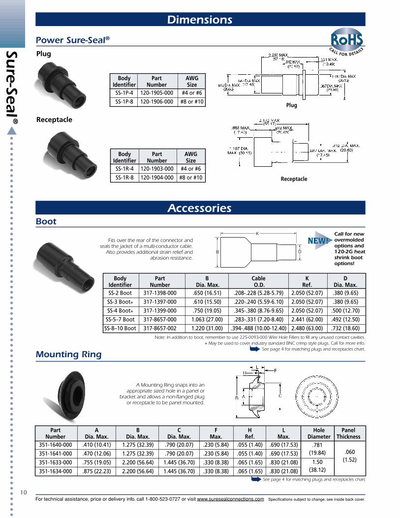
Power Sure-Seal®
Body Part AWGIdentifier Number SizeSS-1P-4 120-1905-000 #4 or #6
SS-1P-8 120-1906-000 #8 or #10
Plug
Body Part AWGIdentifier Number SizeSS-1R-4 120-1903-000 #4 or #6
SS-1R-8 120-1904-000 #8 or #10
Receptacle
Receptacle
Plug
See page 4 for matching plugs and receptacles chart.
Part A B C F H L Hole PanelNumber Dia. Max. Dia. Max. Dia. Max. Max. Ref. Max. Diameter Thickness
351-1640-000 .410 (10.41) 1.275 (32.39) .790 (20.07) .230 (5.84) .055 (1.40) .690 (17.53)
351-1641-000 .470 (12.06) 1.275 (32.39) .790 (20.07) .230 (5.84) .055 (1.40) .690 (17.53)
351-1633-000 .755 (19.05) 2.200 (56.64) 1.445 (36.70) .330 (8.38) .065 (1.65) .830 (21.08)
351-1634-000 .875 (22.23) 2.200 (56.64) 1.445 (36.70) .330 (8.38) .065 (1.65) .830 (21.08)
.060(1.52)
.781(19.84)
1.50(38.12)
A Mounting Ring snaps into anappropriate sized hole in a panel or
bracket and allows a non-flanged plugor receptacle to be panel mounted.
Body Part B Cable K DIdentifier Number Dia. Max. O.D. Ref. Dia. Max.SS-2 Boot 317-1398-000 .650 (16.51) .208-.228 (5.28-5.79) 2.050 (52.07) .380 (9.65)
SS-3 Boot+ 317-1397-000 .610 (15.50) .220-.240 (5.59-6.10) 2.050 (52.07) .380 (9.65)
SS-4 Boot+ 317-1399-000 .750 (19.05) .345-.380 (8.76-9.65) 2.050 (52.07) .500 (12.70)
SS-5–7 Boot 317-8657-000 1.063 (27.00) .283-.331 (7.20-8.40) 2.441 (62.00) .492 (12.50)
SS-8–10 Boot 317-8657-002 1.220 (31.00) .394-.488 (10.00-12.40) 2.480 (63.00) .732 (18.60)
K
B D
Fits over the rear of the connector andseals the jacket of a multi-conductor cable.
Also provides additional strain relief andabrasion resistance.
Note: In addition to boot, remember to use 225-0093-000 Wire Hole Fillers to fill any unused contact cavities.+ May be used to cover industry standard BNC crimp style plugs. Call for more info.
See page 4 for matching plugs and receptacles chart.
Call for newovermoldedoptions and120-2G heatshrink bootoptions!

Sure-Seal
®
Specifications subject to change; see inside back cover.
11For technical assistance, price or delivery info. call 1-800-523-0727 or visit www.suresealconnections.com
Accessories
Mounting Clip (Sure-Seal® only)
Mounting Plate
For 2 – 4 Circuit Plug
Mounting Dimensions
For 8 – 10 Circuit Plug
Mounting Dimensions
MetricThreaded
Hole
066-8516-000for use with120-8552-200
120-8552-201
120-8552-202
120-8552-305
120-8552-306
120-8552-307
066-8516-002 (Through-Hole)for use with
Style Body Part Colors A B C D E F GIdentifier Number Max. +/-.01 Max. Max.
I SS-1C 026-0452-000 Black 2.225 (56.52) .740 (18.80) – – – .210 (5.33) .390 (9.91)
II SS-2C 029-0263-000 Red 2.443 (62.04) .886 (22.50) 1.000 (25.40) .420 (10.67) .420 (10.67) .400 (10.16) .650 (16.51)
II SS-3-4C 029-0262-000 Yellow 2.443 (62.04) .926 (23.52) 1.053 (26.74) .450 (11.43) .480 (12.19) .400 (10.16) .650 (16.51)III SS-5-7C 026-0450-000 Natural 3.045 (77.34) 1.395 (35.43) – – – .610 (15.49) .910 (23.11)
III SS-8-10C 026-0451-000 Black 3.045 (77.34) 1.520 (38.61) – – – .660 (16.76) .960 (24.38)
I IIIII
Use Nutplate part number M85528/2-14A .Use Sealing Screws for mounting, see Accessories page 12.
Use Nutplate part number M85528/2-18A .Use Sealing Screws for mounting, see Accessories on page 12.
Sure-Seal
®
Specifications subject to change; see inside back cover.
12For technical assistance, price or delivery info. call 1-800-523-0727 or visit www.suresealconnections.com
Special Products
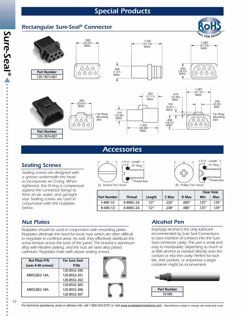
Rectangular Sure-Seal® Connector
.500(1.27)MAX.
1.250(31.75)MAX.
.650(16.51)MAX.
1.080(27.43)MAX.
.510(12.95)MAX.
.697(17.71)MAX.
1.405(35.69)MAX.
.940(23.87)MAX.
Part Number120-1874-007
.940(23.87)MAX.
Tie WrapMountingSlot
1.067(27.10)MAX.
.250(6.35)MIN.
.510(12.95)MAX.
.150(3.81)MAX.
.650(16.51)MAX.
Tie WrapMountingSlot
Part Number120-1873-007
Sealing Screws
Nut PlatesNutplates should be used in conjunction with mounting plates.Nutplates eliminate the need for loose nuts which are often difficultto negotiate in confined areas. As well, they effectively distribute thescrew tension across the back of the panel. The bracket is aluminumalloy with Alodine plating, and the nuts are steel alloy platedcadmium. Nutplates mate with above sealing screws.
Alcohol PenIsopropyl alcohol is the only lubricantrecommended by Sure Seal Connectionsto ease insertion of contacts into the SureSeal connector cavity. This pen is small andeasy to manipulate, dispensing as much oras little alcohol as needed directly onto thecontact or into the cavity. Perfect for toolkits, shirt pockets, or anywhere a largercontainer might be inconvenient.
Nut Plate P/N For Sure Seal (uses 4-40 screws) P/Ns
120-8552-200 M85528/2-14A 120-8552-201
120-8552-202120-8552-305
M85528/2-18A 120-8552-306120-8552-307
Clear Hole Part Number Thread Length C Max D Max Min Max
S-440-1/2 4-40NC-2A 1/2" .220" .069" .125" .129"
R-440-1/2 4-40NC-2A 1/2" .238" .080" .125" .129"
C D Length
"O" Ring
Thread Size
C D Length
"O" Ring
Thread Size
Accessories
(S) Slotted Pan Head (R) Phillips Pan Head
Part Number1610N
Sealing screws are designed witha groove underneath the headto incorporate an O-ring. Whentightened, the O-ring is compressedagainst the connector flange toform an air, water, and gas-tightseal. Sealing screws are used inconjunction with the nutplatesbelow.
Sure-Seal
®
Specifications subject to change; see inside back cover.
13For technical assistance, price or delivery info. call 1-800-523-0727 or visit www.suresealconnections.com
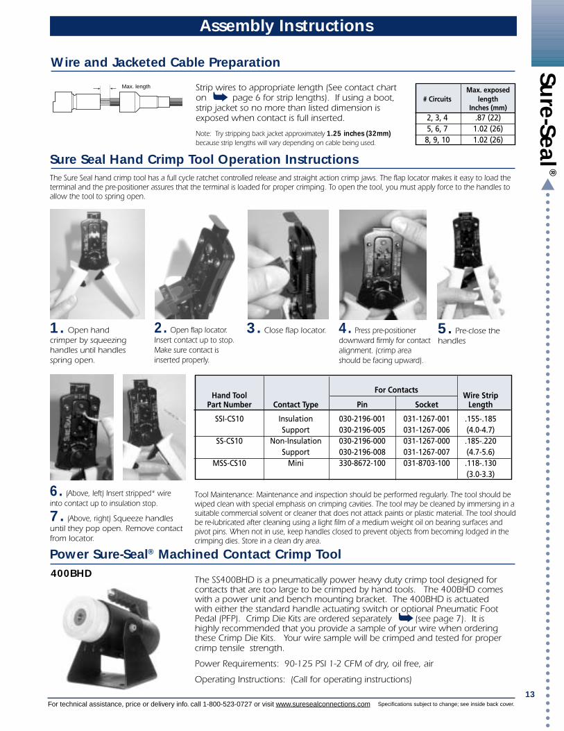
Assembly Instructions
2. Open flap locator.Insert contact up to stop.Make sure contact isinserted properly.
3. Close flap locator.
Wire and Jacketed Cable Preparation
Sure Seal Hand Crimp Tool Operation Instructions
Power Sure-Seal® Machined Contact Crimp Tool
The SS400BHD is a pneumatically power heavy duty crimp tool designed forcontacts that are too large to be crimped by hand tools. The 400BHD comeswith a power unit and bench mounting bracket. The 400BHD is actuatedwith either the standard handle actuating switch or optional Pneumatic FootPedal (PFP). Crimp Die Kits are ordered separately (see page 7). It ishighly recommended that you provide a sample of your wire when orderingthese Crimp Die Kits. Your wire sample will be crimped and tested for propercrimp tensile strength.
Power Requirements: 90-125 PSI 1-2 CFM of dry, oil free, air
Operating Instructions: (Call for operating instructions)
Max. exposed# Circuits length
Inches (mm)2, 3, 4 .87 (22)5, 6, 7 1.02 (26)8, 9, 10 1.02 (26)
Strip wires to appropriate length (See contact charton page 6 for strip lengths). If using a boot,strip jacket so no more than listed dimension isexposed when contact is full inserted.
Note: Try stripping back jacket approximately 1.25 inches (32mm)because strip lengths will vary depending on cable being used.
Max. length
400BHD
1. Open handcrimper by squeezinghandles until handlesspring open.
5. Pre-close thehandles
6. (Above, left) Insert stripped* wireinto contact up to insulation stop.
7. (Above, right) Squeeze handlesuntil they pop open. Remove contactfrom locator.
4. Press pre-positionerdownward firmly for contactalignment. (crimp areashould be facing upward).
The Sure Seal hand crimp tool has a full cycle ratchet controlled release and straight action crimp jaws. The flap locator makes it easy to load theterminal and the pre-positioner assures that the terminal is loaded for proper crimping. To open the tool, you must apply force to the handles toallow the tool to spring open.
Tool Maintenance: Maintenance and inspection should be performed regularly. The tool should bewiped clean with special emphasis on crimping cavities. The tool may be cleaned by immersing in asuitable commercial solvent or cleaner that does not attack paints or plastic material. The tool shouldbe re-lubricated after cleaning using a light film of a medium weight oil on bearing surfaces andpivot pins. When not in use, keep handles closed to prevent objects from becoming lodged in thecrimping dies. Store in a clean dry area.
Hand Tool Wire StripPart Number Contact Type Pin Socket Length
SSI-CS10 Insulation 030-2196-001 031-1267-001 .155-.185Support 030-2196-005 031-1267-006 (4.0-4.7)
SS-CS10 Non-Insulation 030-2196-000 031-1267-000 .185-.220Support 030-2196-008 031-1267-007 (4.7-5.6)
MSS-CS10 Mini 330-8672-100 031-8703-100 .118-.130(3.0-3.3)
For Contacts
Sure-Seal
®
Specifications subject to change; see inside back cover.
14For technical assistance, price or delivery info. call 1-800-523-0727 or visit www.suresealconnections.com
Applicator Terminal
SSMA-SSI 110238-0195 & 110238-0194
SSMA-SS 110238-0040 & 110238-0085
MSSMA-SSI 121348-0100 & 121347-0100
Assembly Instructions
1 32
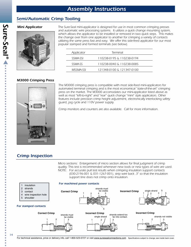
Incorrect Crimp
1
Incorrect Crimpsingle strand
2 3
strands extend toofar into contact.
For stamped contacts
1 2 3
strands must be visible
Correct Crimp
Incorrect Crimp5
1 4 32single strand 5Correct Crimp
strands must be visible
1 2 34
5
For machined power contacts1 insulation2 strands3 contact4 wire inspection hole5 shoulder
Mini Applicator
Semi/Automatic Crimp Tooling
Crimp Inspection
M3000 Crimping Press
strands not visible
Micro sections: Enlargement of micro section allows for final judgment of crimpquality. This test is recommended whenever new tools or new types of wire are used.NOTE: For accurate pull test results when crimping insulation support contacts
(030-2196-001 & 031-1267-001), strip wire back .3" so that the insulationsupport tine does not crimp onto insulation.
The Sure-Seal mini-applicator is designed for use in most common crimping pressesand automatic wire processing systems. It utilizes a quick change mounting system,which allows the applicator to be installed or removed in two quick steps. This makesthe change over from one applicator to another for crimping a variety of contactsutilizing the same press fast and easy. We offer this side-feed applicator for our mostpopular stamped and formed terminals (see below).
The M3000 crimping press is compatible with most side-feed mini-applicators forautomated terminal crimping and is the most economical "state-of-the-art" crimpingpress on the market. The M3000 accomodates our mini-applicator listed above aswell as most "left-to-right" and "rear" quick change "mini" style applicators. Otherfeatures include precision crimp height adjustment, electronically interlocking safetyguard, jog cycle and 110V power supply.
Crimp monitors and counters are also available. Call for more information.

Sure-Seal
®
Specifications subject to change; see inside back cover.
15For technical assistance, price or delivery info. call 1-800-523-0727 or visit www.suresealconnections.com
1. Affix proper connector holding block to stable surface (i.e. vice or table).See Connector Selection table, page 5, for proper holding block.
2. If a jacket wire sealing boot is to be used, it mustbe slid up the cable (isopropyl alcohol will help indoing this).
3. Dip connector in isopropyl alcohol and place inholding block with the back end up (wire side).
4. Using proper contact insertion tool, (see ContactSelection table for proper tool):A. place contact in groove of toolB. make sure that end of the tool is up against
the shoulder of the contact.
5. Insert contact into proper cavity of the connector body by applyingconstant pressure until contact snaps into place. Isopropyl alcohol willhelp in doing this. (Warning: Do not tilt the tool during the insertion).
6. Insert all remaining contacts. To insure environmental sealing of theconnector any empty contact cavities must be filled with wire hole fillers(see Contact Selection table, page 5, for proper wire hole filler).
7. Check mating side of the connector to be sure that all contacts are onthe same plane (fully inserted).
8. If you are using jacket sealing boot, slide the boot down the cable andonto the connector.
9. Remove connector and wire assembly from holding block.
Assembly Instructions
Manual Insertion of Contacts
The CBIT-SS-150 Sure-Seal® insertion machine is pneumatically powered, and micropro-cessor controlled. It is designed to insert pre-crimped wires into the standard Sure-Seal®
plug and receptacle housings for moderate to high volume applications. This machineis used for SS2P/R through SS10P/R including the 120-1873-007 and 120-1874-007rectangular style Sure-Seal® connectors.
The benefits of using this insertion machine are:•Ease of operation Short operator training time
Reduces operator fatigue and insertion errorsQuick change over for different connectors sizes
•Low cycle time Much faster than manual insertion•High connector integrity Lower chance of damaging the wire sealing ripples
Power Requirements: Electrical = 115 Vac, 60 HzPneumatic = 80 PSI, 10 CFM dry oil free filtered air
Pneumatic Automatic Insertion Tool (Leased)
Extraction of Contacts
1. Slide up any rear accessories (i.e. jacket cablesealing boots). Using isopropyl alcohol will helpyou slide these up your cable.
2. Grasp individual wire firmly and gently pull thecontact out of the connector.
* Extraction tool available DRK32 & DRK152, please call.
CBIT-SS-150

Sure-Seal
®
Specifications subject to change; see inside back cover.
16For technical assistance, price or delivery info. call 1-800-523-0727 or visit www.suresealconnections.com
Requirements
Sure-Seal® connectors when mated shall form an environmental seal against water, moisture, aqueous solutions, oils and certain chemicals as well asdust and dirt. Tests include immersion in 3 feet depth in water solution containing 5% salt.The minimum tensile load required to separate the wire from the contact, either by pulling the wire out of the crimp joint or breaking the wire withinthe crimp joint, shall not be less than the applicable limits as specified. Wire breakage, or contact damage not due to crimping, at less than tensileloads shall not constitute failure.
Properly assembled and mated connectors shall be tested in accordance with MIL-STD-202, Method 302, except a potential of 500 ± 15 volt DC shallbe used. The resistance shall be measured between adjacent parts of contacts (or contacts to ground for SS-1) and shall not be less than 100 MΩ. Ifthe specimen has been immersed in fluid in the preceding test, it shall be placed wet on a conducting surface and insulation resistance measuredwithin 5 minutes between each contact and also between each contact and the conducting surface (except for SS-1 to be measured contact toground while immersed).Assembled and mated connectors shall show no evidence of breakdown between adjacent contacts (or contact to ground for SS-1) when tested inaccordance with MIL-STD-202, Method 301, and a test voltage of 1200 ± 15 volts A.C.
The contact resistance of mated contacts shall be such that the resistance measured across the contacts and 5/8" behind the crimp junction shall notexceed 10 mΩ. Test current to be 1 amp, and MIL-STD-202, Method 307.Mated connectors properly mounted shall be subjected to the shock test in accordance with MIL-STD-202, Method 213B, CONDITION B. The shocktest shall be repeated three (3) times in each of X, Y & Z axis. Suitable means shall be employed to monitor the current flow. Current discontinuity of 1microsecond or more, disengagement of the mated connectors, evidence of cracking, breaking or loosening of parts shall be cause for rejection.Properly assembled and mated connectors shall be mounted to the vibration table, with the wire leads strapped to a vibrating member approximately3 inches from each end of the connector body and vibrated with a peak-to-peak amplitude of .25 inch across a frequency range of 5 to 39Hz, and a±20g acceleration across 39 to 55 Hz, swept up in one minute and down in another minute. The vibration shall be swept up and down for a total of36 hours under the following conditions:
Six (6) hours at 180°F (82°C) along the longitudinal axisSix (6) hours at 180°F (82°C) along a perpendicular axisSix (6) hours at room temperature along the longitudinal axisSix (6) hours at room temperature along a perpendicular axisSix (6) hours at -40°F (-40°C) along the longitudinal axisSix (6) hours at -40°F (-40°C) along a perpendicular axis
The connectors shall be connected in a series circuit with a minimum of 0.1 ampere flowing through the contacts. Electrical continuity shall becontinually monitored. Breaks in continuity longer than one microsecond shall be cause for rejection.The connectors shall be subjected to 25 cycles of mating and unmating at -10°C and another 25 cycles at 50°C. There shall be no evidence ofdamage to the contacts, the contact plating, the insulators or sealing rings, which would be detrimental to connector function.With the connector plug or receptacle held firmly, an axial dead weight of 7.5 lbs. shall be imposed on each wire for one minute without the contactsbeing dislodged from the connector. Plugs and receptacles to be tested separately.Each wired receptacle and plug shall be subjected to 5 cycles of contact insertion and extraction in the same cavity using the approved tools. Plugand receptacle are to be tested separately. After the 5 cycles of insertion and extraction, each plug and receptacle in turn will be subjected to thecontact retention test of 6 lbs. per paragraph 4.4.7.Using an assembled and mated connector with the receptacle held firmly by the wires, a load shall be applied to the wires of the plug until theconnector is completely separated. The rate of loading shall be one inch per minute. The sample shall fall within the limits specified as follows:
Unmating Forces (lbs.) Unmating Forces (lbs.)Connector Size max. min. Connector Size max. min.
SS-1 12 6 SS-4 20 9SS-2 15 6 SS-5/7 30 10SS-3 18 8 SS-8/10 55 10
Wired and mated connectors shall be subjected to the applicable fluids for the length of time specified. Following the test the connectors shall beimmersed to a depth of 3 feet in salt water for 24 hours at room temperature. At the completion of the salt water immersion test and while stillimmersed insulation resistance shall be measured. Failure to meet the insulation resistance requirements shall be cause for rejection.
Gasoline Splash 1 second dip - 3 minute air dry for 80 cycles at room ambient temperature.Diesel Fuel Splash 1 second dip - 3 minute air dry for 80 cycles at room ambient temperature.Automotive Lubricating Oil Immersed in S.A.E. 30 weight lubricating oil for 1 hour.Antifreeze Immersed at 120°F (49°C) for 48 hours.Brake Fluid Immersed at room ambient temperature for 24 hours.Automatic Transmission Fluid Immersed at 120°F (49°C) for 48 hours.Gasoline Vapor Immersed in a gasoline vapor atmosphere at room temperature for 48 hours.
Wired and properly mated connectors shall be subjected to ozone test per ASTMD-1149 except that 100 ppm of ozones shall be used. The duration ofthe test shall be 7 days. Outdoor exposure to be conducted per ASTM D-1171. The connector shall show no cracking or other degradation whichwould result in loss of sealing integrity.Wired mated connectors shall be tested in accordance with MIL-STD-202 Method 108A, Test Condition D at 105°C for 1000 hours. Following the test,they shall be subjected to 3 feet salt water immersion for 24 hours. While immersed, insulation resistance shall be determined. Failure to meet theinsulation resistance requirements shall be cause for rejection.Sure Seal Connections has recently completed testing of the Sure Seal PVC Nitrile material (SM 3400-06) for UV resistance. The material was tested inaccordance with ASTM G-26 (Xenon Arc), 720 hours exposure with no loss in tensile strength and greater than 75% retention of elongation.
Test DataSure-Seal® Circular ConnectorsTypical: Power Sure-Seal®, Flange Sure-Seal®, and Mini Sure-Seal® are essentially the same except for mechanical and amperagecapacity differences. Sure-Seal® products are designed to meet specification CS-155. Items of most general interest to users anddesigners are listed below. With its current capability and large size, Power Sure-Seal® contacts and currents are covered in CS-169.
Test ReferenceDescription Paragraph
Environmental 3.5.1SealingContact 3.6.12TensileStrength–Crimp
Insulation 4.4.1Resistance
Dielectric 4.4.2WithstandingVoltage
Contact 4.4.3ResistanceShock 4.4.4
Vibration 4.4.5
Durability 4.4.6
Contact 4.4.7Retention
Maintenance 4.4.8Aging
Connector 4.4.11SeparatingForce
SolventResistance
4.4.134.4.144.4.154.4.164.4.174.4.184.4.19
Weather 4.4.20and OzoneResistance
High 4.4.23TemperatureLong-Term
UV -
Crimp Tensile Strength, Pounds MinimumWithout With Without With Without With
Insulation Insulation Insulation Insulation Insulation InsulationWire Size Support Support Wire Size Support Support Wire Size Support Support
AWG Contacts Contacts AWG Contacts Contacts AWG Contacts Contacts4 140 — 10 80 — 18 25 256 100 — 14 35 35 20 — 208 90 — 16 35 35
16
Caution: “Sure-Seal® connectors are rated for use between temperatures of -40 to + 105 degrees Celsius. However, if a Sure-Seal® connector is exposed for long periods oftime to temperatures exceeding 85 degrees Celsius and is unmated, it may lose its environmental sealing integrity upon remating. Thus, we recommend that both theplug and receptacle be replaced if environmental sealing is required after remating.”