
SURE-SEAL® CONNECTOR
16
SURE-SEAL ® CONNECTOR SURE-SEAL ® CONNECTOR COST-EFFECTIVE ENVIRONMENTALLY-SEALED CONNECTOR A low-profile, one-piece, resilient body and rugged, multiple moisture seals make Sure-Seal ® connectors a natural choice for outdoor applications where contaminants are a concern. Only two parts are required to complete a Sure-Seal ® connector: the connector body and the contacts. Sure-Seal ® was developed to address Department of Transportation safety regulations for automotive connectors. Sure-Seal ® is used in a range of environmental applications where a small, low-cost connector is needed. These sealed connectors meet or exceed DOT requirements for shock, vibration, temperature cycling, salt water spray and immersion, petroleum derivatives, and industrial gas while insuring low milli-volt drop and low contact resistance. Sure-Seal ® connectors are excellent for motorcycles, automobiles, boats, and demanding off- road vehicles. Sure-Seal ® will operate -40°F to +221°F under high humidity, severe vibration, ice and/or mud. Connector sealing resists brake fluid, gasoline, diesel fuel, anti-freeze, ultraviolet, ozone, and steam. For full details, please see the product specifications below. APPLICATIONS FEATURES LOW INSTALLED COST One piece molded bodies and crimp contacts provide a low cost solution. In addition, these connectors can be easily terminated by the user. WATER SUBMERSIBLE Not just splash-proof, but truly submersible for short periods of time. Sure-Seal ® will seal to the requirements of IP67 and DIN 400 50. RESISTANT TO AUTOMOTIVE/INDUSTRIAL ENVIRONMENTS Sure-Seal ® will operate in temperatures from -40°F to +221°F under conditions of high humidity, severe vibration, ice and mud. Sealing integrity is maintained with exposure to brake fluid, gasoline, diesel fuel, antifreeze, ultraviolet, ozone, and steam. WIDE RANGE OF WIRE GAUGES AND CURRENT CARRYING CAPABILITY Up to 85 amps with wire gauges from size 20 up to size 4 AWG wire. ONE-PIECE CONNECTOR Up to 30 amps per contact with wire sizes from 28 AWG up to 12 AWG wire. TNM 700-volt handles up to 40 amp power for up to 8 AWG wire. FIELD SERVICEABLE The use of removable crimp contacts allows Sure-Seal ® connections to be changed or modified in the field if necessary. POLARIZED AGAINST MIS-MATES Connector halves use both pin and socket contacts. The plug and receptacle must be properly oriented for the connectors to mate. Raised indexing ribs in conjunction with a stepped plane allow blind mating of the connector halves even in dark or cramped spaces. THREE SURE-SEAL ® VERSIONS Sure-Seal ® is available in three versions. The basic Sure-Seal ® line is the broadest and ideal for most applications. Mini-Sure-Seal ® provides a slightly smaller connector in a limited range of configurations. Power Sure-Seal ® is for single circuit, high power applications. • Automotive • Marine • Appliances • Trucks & buses • Off-road vehicles • Industrial machinery • IP67 & DIN 400 50 environments
Transcript of SURE-SEAL® CONNECTOR

SURE-SEAL
® CO
NN
ECTO
R
SURE-SEAL® CONNECTORCOST-EFFECTIVE ENVIRONMENTALLY-SEALED CONNECTORA low-profile, one-piece, resilient body and rugged, multiple moisture seals make Sure-Seal® connectors a natural choice for outdoor applications where contaminants are a concern. Only two parts are required to complete a Sure-Seal® connector: the connector body and the contacts. Sure-Seal® was developed to address Department of Transportation safety regulations for automotive connectors. Sure-Seal® is used in a range of environmental applications where a small, low-cost connector is needed. These sealed connectors meet or exceed DOT requirements for shock, vibration, temperature cycling, salt water spray and immersion, petroleum derivatives, and industrial gas while insuring low milli-volt drop and low contact resistance. Sure-Seal® connectors are excellent for motorcycles, automobiles, boats, and demanding off-road vehicles. Sure-Seal® will operate -40°F to +221°F under high humidity, severe vibration, ice and/or mud. Connector sealing resists brake fluid, gasoline, diesel fuel, anti-freeze, ultraviolet, ozone, and steam. For full details, please see the product specifications below.
APPLICATIONS
FEATURES LOW INSTALLED COST One piece molded bodies and crimp contacts provide a low cost solution. In addition, these connectors can be easily terminated by the user.
WATER SUBMERSIBLE Not just splash-proof, but truly submersible for short periods of time. Sure-Seal® will seal to the requirements of IP67 and DIN 400 50.
RESISTANT TO AUTOMOTIVE/INDUSTRIAL ENVIRONMENTS Sure-Seal® will operate in temperatures from -40°F to +221°F under conditions of high humidity, severe vibration, ice and mud. Sealing integrity is maintained with exposure to brake fluid, gasoline, diesel fuel, antifreeze, ultraviolet, ozone, and steam.
WIDE RANGE OF WIRE GAUGES AND CURRENT CARRYING CAPABILITY Up to 85 amps with wire gauges from size 20 up to size 4 AWG wire.
ONE-PIECE CONNECTOR Up to 30 amps per contact with wire sizes from 28 AWG up to 12 AWG wire. TNM 700-volt handles up to 40 amp power for up to 8 AWG wire.
FIELD SERVICEABLEThe use of removable crimp contacts allows Sure-Seal® connections to be changed or modified in the field if necessary.
POLARIZED AGAINST MIS-MATES Connector halves use both pin and socket contacts. The plug and receptacle must be properly oriented for the connectors to mate. Raised indexing ribs in conjunction with a stepped plane allow blind mating of the connector halves even in dark or cramped spaces.
THREE SURE-SEAL® VERSIONSSure-Seal® is available in three versions. The basic Sure-Seal® line is the broadest and ideal for most applications. Mini-Sure-Seal® provides a slightly smaller connector in a limited range of configurations. Power Sure-Seal® is for single circuit, high power applications.
• Automotive
• Marine
• Appliances
• Trucks & buses
• Off-road vehicles
• Industrial machinery
• IP67 & DIN 400 50 environments
SURE-SEAL
® CO
NN
ECTO
R
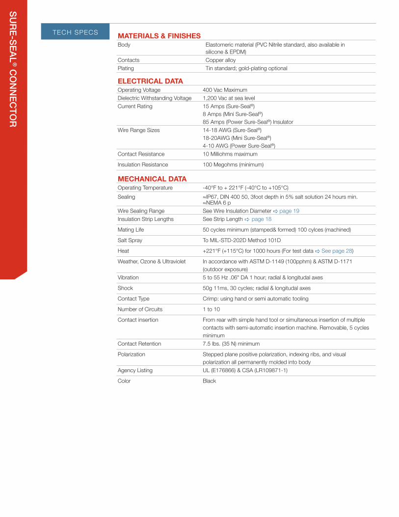
TECH SPECS MATERIALS & FINISHES Body Elastomeric material (PVC Nitrile standard, also available in
silicone & EPDM)Contacts Copper alloyPlating Tin standard; gold-plating optional
ELECTRICAL DATA Operating Voltage 400 Vac MaximumDielectric Withstanding Voltage 1,200 Vac at sea levelCurrent Rating 15 Amps (Sure-Seal®)
8 Amps (Mini Sure-Seal®)85 Amps (Power Sure-Seal®) Insulator
Wire Range Sizes 14-18 AWG (Sure-Seal®)18-20AWG (Mini Sure-Seal®)4-10 AWG (Power Sure-Seal®)
Contact Resistance 10 Milliohms maximum
Insulation Resistance 100 Megohms (minimum)
MECHANICAL DATA Operating Temperature -40°F to + 221°F (-40°C to +105°C)Sealing ≈IP67, DIN 400 50, 3foot depth in 5% salt solution 24 hours min.
≈NEMA 6 pWire Sealing Range See Wire Insulation Diameter a page 19Insulation Strip Lengths See Strip Length a page 18
Mating Life 50 cycles minimum (stamped& formed) 100 cylces (machined)
Salt Spray To MIL-STD-202D Method 101D
Heat +221°F (+115°C) for 1000 hours (For test data a See page 28)
Weather, Ozone & Ultraviolet In accordance with ASTM D-1149 (100pphm) & ASTM D-1171 (outdoor exposure)
Vibration 5 to 55 Hz .06" DA 1 hour; radial & longitudal axes
Shock 50g 11ms, 30 cycles; radial & longitudal axes
Contact Type Crimp: using hand or semi automatic tooling
Number of Circuits 1 to 10
Contact insertion From rear with simple hand tool or simultaneous insertion of multiple contacts with semi-automatic insertion machine. Removable, 5 cycles minimum
Contact Retention 7.5 lbs. (35 N) minimum
Polarization Stepped plane positive polarization, indexing ribs, and visual polarization all permanently molded into body
Agency Listing UL (E176866) & CSA (LR109871-1)
Color Black

SURE-SEAL
® CO
NN
ECTO
R
CROSS SECTION
WIRE HOLE FILLER (OPTIONAL)
OPTIONAL BOOT
OVER MOLD MODELS
HOW TO SELECT SURE-SEAL® CONNECTOR & ACCESSORIES
HOW TO SELECT SURE-SEAL® CONTACTS & TOOLING
STEP 1. Choose series: Sure-Seal®, Mini Sure-Seal®, or Power Sure-Seal®
STEP 2. Determine number of circuits required per connector: 1 to 10 in Sure-Seal® 2 to 4 in MINI Sure-Seal® 1 in POWER Sure-Seal®
STEP 3. Select connector with appropriate number of circuits.
STEP 4. Select Sure-Seal® body style: straight or flanged plug and receptacle.
STEP 5. Select connector accessories: Boots, Mounting Ring, Mounting Plates, Mounting Clip, Wire Hole Filler, Holding Blocks.
STEP 1. Determine current carrying and wire gauge requirements for application.
STEP 2. Select appropriate contacts from contact selection chart. a page 18
STEP 3. Choose appropriate crimp, insertion, and extraction tooling. a page 19

SURE-SEAL
® CO
NN
ECTO
R
Machined PC PinContact. Please contact us.
NUMBER OF CIRCUITS AWG WIRE SIZE PLUG FLANGED PLUG RECEPTACLE
SURE-SEAL®
1 14-18 120-1832-000 -** 120-1833-000
2 14-18 120-1807-000 120-8552-200 120-1804-000
3First make last break verison 14-18 “120-1808-000
120-1808-200” 120-8552-201 120-1805-000120-1805-200
4 14-18 120-1809-000 120-8552-202 120-1806-000
5 14-18 120-1841-000 -** 120-1839-000
6 14-18 120-1842-000 -** 120-1840-000
7 14-18 120-1873-000 -** 120-1874-000
8 14-18 120-1865-000 120-8552-305 120-1866-000
9 14-18 120-1867-000 120-8552-306 120-1868-000
10 14-18 120-1869-000 120-8552-307 120-1870-000
MINI SURE-SEAL®
2 18-20 120-8552-100 - 120-8551-100
3 18-20 120-8552-101 - 120-8551-101
4 18-20 120-8552-102 - 120-8551-102
POWER SURE-SEAL®
1 4-6 120-1905-000order socket contacts - 120-1903-000
order pin contacts
1 8-10 120-1906-000order socket contacts - 120-1904-000
order pin contacts
* a See page 24 for special rectangular version ** Use Mounting Rings a See page 22
CONNECTORSLAYOUTS
*
Notice that all multi-pin Sure-Seal® connectors use a combination of pin and socket contacts in each connector.
View from mating face of receptacle
l pin
m socket

SURE-SEAL
® CO
NN
ECTO
R
NUMBER OF
CIRCUITSBOOT(1)
MOUNTING RING(2)
MOUNTING PLATE(3)
POSI-LOKMOUNTING
CLIP(4)
WIRE HOLEFILLER(5)
HOLDING BLOCK(6)
SURE-SEAL®
1 - - - 026-0452-000 225-0093-000 317-1408-002
2 317-1398-000 351-1640-000 066-8516-000 029-0263-000 225-0093-000 317-1408-001
3 317-1397-000# 351-1641-000 066-8516-000 029-0262-000 225-0093-000 317-1408-000
First make last break
version317-1399-000# 351-1641-000 066-8516-000 029-0262-000 225-0093-000 317-1408-000
4 317-1397-000#317-1399-000# 351-1641-000 066-8516-000 029-0262-000 225-0093-000 317-1408-000
5 317-8657-000 351-1633-000 - 026-0450-000 225-0093-000 317-1408-003
6 317-8657-000 351-1633-000 - 026-0450-000 225-0093-000 317-1408-003
7 317-8657-000 351-1633-000 - 026-0450-000 225-0093-000 317-1408-003
8 317-8657-002 351-1634-000 066-8516-002 026-0451-000 225-0093-000 317-1408-004
9 317-8657-002 351-1634-000 066-8516-002 026-0451-000 225-0093-000 317-1408-004
10 317-8657-002 351-1634-000 066-8516-002 026-0451-000 225-0093-000 317-1408-004
MINI SURE-SEAL®
2 - - - 026-0452-000 225-1012-000 195-8508-013 Plug 195-8508-014 receptacle
3 - - - 026-0452-000 225-1012-000 195-8508-015 plug 195-8508-016 receptacle
4 - - - 026-0452-000 225-1012-000 195-8508-017 plug 195-8508-018 receptacle
POWER SURE-SEAL®
1 - - - - - -1 - - - - - -
* a See page 24 for special rectangular version# # a See page 22 for Cable O.D. accommodations
ACCESSORIES
(1) Boot: Fits over the rear of the connector and seals the jacket of the cable. It also provides additional strain relief and abrasion resistance. See dimensions on a page 22 for choosing 3 or 4 circuit boot. (2) Mounting Ring: A Mounting Ring snaps into an appropriate sized hole in a panel or bracket and allows a non-flanged plug or receptacle to be panel mounted.
(3) Mounting Plate: Metal mounting plates reinforce the molded flanges when attaching flanged connectors to a panel.(4) Mounting Clip: Mounting clips can be used free-hanging as a positive lock to provide a secondary means of securing the connector halves. Mated connector pairs can be snapped into the clip for fixed mounting using a screw or cable tie. The wires of one of the connectors can be passed through an integral retention ring which captivates one of the connector halves to the clip.
(5) Wire Hole Fillers: Wire Hole fillers are inserted into unused cavities in place of a contact. Hole fillers are required to retain the watertight sealing if less than a full compliment of contacts are to be used.(6) Holding Block: A holding block makes insertion of contacts into the molded body faster and avoids personal injury or damage to the connector. It is highly recommended that the appropriate block be used when inserting contacts. (a See page 27 for assembly instructions.)
LAYOUTS
Notice that all multi-pin Sure-Seal® connectors use a combination of pin and socket contacts in each connector.
View from mating face of receptacle
l pin
m socket
*

SURE-SEAL
® CO
NN
ECTO
R
INDEX CONTACTS (1) WIRE
COLUMN 1 COLUMN 2 COLUMN 3 COLUMN 4 COLUMN 5 COLUMN 6 COLUMN 7
CONTACT STYLE AWG WIRE SIZE LOOSE PINS 5K REEL PINS(1) LOOSE SOCKET 5K REEL SOCKETS(1)STRIP LENGTH INCHES (MM)
SURE-SEAL® INSULATION SUPPORT
SS 8 circuit plug
Tin Plating (Standard) 14-18 030-2196-001 110238-0195 031-1267-001 110238-0194.155 - .185
(3.94 - 4.70mm)Gold Plating* 14-18 030-2193-006 110238-0409 031-1267-005 110238-0408
SURE-SEAL® NON-INSULATION SUPPORT
.185 - .220(4.70 - 5.59mm)
Tin Plating (Standard) 14-18 030-2196-000 110238-0040 031-1267-000 110238-0085
Gold Plating* 14-18 030-2196-008 110238-0440 031-1267-007 110238-0442
MINI SURE-SEAL® INSULATION SUPPORT
RoHS .118 - .130(3.00 - 3.30mm)
18-20 330-8672-100 121348-0100 031-8703-100 121347-0100
POWER SURE-SEAL (VE)**
.460 - .480(11.7 - 12.2mm)
4 030-2245-002 - 031-1295-001 -
6 030-2245-001 - 031-1294-001 - Note: 6 AWG & 10 AWG socket contacts have unique strip
lengths.515 - .535 (13.1 - 13.6)
8 030-2244-001 - 031-1299-001 -
10 030-2244-002 - 031-1298-001 -
NEW MACHINED FIRST-MATE LAST-BREAK / PRE-EARTH CONTACTS FOR 120-1808-200 & 120-1805-200 FOR CAVITY 1 ONLY
Silver plated 16-20 for 120-1808-200 use SSFMLB16-16S for 120-1805-200 use SSFMLB16-16P .245 (6.2)
Gold plated 16-20 for 120-1808-200 use SSFMLB16-16SG for 120-1805-200 use SSFMLB16-16PG .245 (6.2)
* Silver available 50K minimum, please contact us. ** VE can be used with ITT CANNON VE connectors and Deutsch HD connectors. NOTE: Sure-Seal® and Mini Sure-Seal® contacts are available in machined contact versions. Contact us for information. Power Sure-Seal® contacts are machined contacts. (1) Loose Piece or 5K Reel Contacts are available loose piece or on continuous reels of 5000 pieces for use with semi-automated crimping systems.

SURE-SEAL
® CO
NN
ECTO
RRANGE TOOLING
COLUMN 1 COLUMN 2 COLUMN 8 COLUMN 9 COLUMN 10 COLUMN 11 COLUMN 12 COLUMN 13
CONTACT STYLE
AWG WIRE SIZE
WIRE INSULATION DIAMETER
WIRE HOLE FILLER(2)
INSERTION TOOL(3)
CRIMP TOOL(4)EXTRACTION
TOOL POWER/AUTOMATIC TOOL(5)
SURE-SEAL® INSULATION SUPPORT
Tin Plating (Standard)
Gold Plating*
14-18
SS 8 circuit plug
.100 - .147(2.54 - 3.73mm)
225-0093-000 Replacement Tip 317-1153-017
Sure Seal
PUSH
Tel: 888-308-7873
replacement locator
1181-92001
DRK 152
Mini Applicator (6) a See page 25-26
CBIT-SS-150 a See page 27
M3000 a See page 26
SSI-T-TOOL or 070306-0000 SSI-CS10
SURE-SEAL® NON-INSULATION SUPPORT
Tin Plating (Standard)
Gold Plating*
14-18 .100 - .147(2.54 - 3.73mm) 225-0093-000
Replacement tip 317-1153-015
Replacement locator
1181-92001DRK 152
SS-T-TOOL or 070235-0001 SS-CS10
MINI SURE-SEAL® INSULATION SUPPORT
Tin Plating (Standard)
Gold Plating*
18-20 .055 - .071(1.40 - 1.80mm) 225-1012-000
Replacement tip MSS2000-TIP
Replacement locator
1181-89005DRK 32
MSS-T-TOOL orMSS-2000 MSS-CS10
POWER SURE-SEAL (VE)** CRIMP TOOL CRIMP KIT
4.247 - .380
(6.96 - 9.65mm)
-
CIT-VE4-6
-
400BHD
Kit Contains: Crimp Die,
Locators, and Go / No-Go
Gauge. Provide sample of wire when ordering. (Call for more information.)
6 -
8
.159 - .245(4.04 - 6.22mm)
-
CIT-VE-8-10
10 -
NEW MACHINED FIRST-MATE LAST-BREAK / PRE-EARTH CONTACTS FOR 120-1808-200 & 120-1805-200 FOR CAVITY 1 ONLY
Silver plated
Gold plated16-20 .100-.147
(2.54-3.73) - 076303-000 AF8 with TH452 DRK 152 WA24F TH452
2) Wire Hole Fillers: These fillers are inserted into unused cavities in place of a contact. Wire hole fillers are required to retain the watertight sealing if less than a full compliment of contacts are to be used. (3) Insertion Tool: An Insertion tool is required to insert contacts into the connector. These tools are heavy duty production hand tools. A holding block should also be used during the insertion process. An extraction tool is not required. See assembly instructions. Semi-Automatic insertion tools are also available. a See page 26
(4) Hand Crimp Tools: These are heavy duty tools with a ratchet mechanism that will only release the contact when the crimp is completed. These tools produce consistent, high quality crimps. They are the only hand crimping tools recommended for Sure-Seal contacts.
(5) Semi-Automatic Crimp Tools: For high volume applications, several types of semi-automatic crimping tools are available for all Sure-Seal contacts. a See page 26-27
(6) Mini applicator for insulation support Fore Sure-Seal stamped contacts. Mini applicator modules are used in indusrty standard crmp presses. This allows for fast changeover for crimping different contacts and by using the same crimp press, saves valuable factory floor space versus having to use multiple presses.

SURE-SEAL
® CO
NN
ECTO
R
DIMENSIONS
BODY IDENTIFIER PLUG NUMBER (P) RECEPTACLE NUMBER (R) A DIA MAX. B DIA MAX. C MAX.
SS-1 P/R 120-1832-000 120-1833-000 .380 (9.65) .550 (13.97) .230 (5.84)
SS-2 P/R* 120-1807-000 120-1804-000 .550 (13.97) .710 (18.03) .430 (10.92)
SS-3 P/R* 120-1808-000 120-1805-000 .600 (15.24) .760 (19.30) .500 (12.70)
SS-4 P/R* 120-1809-000 120-1806-000 .600 (15.24) .760 (19.30) .500 (12.70)
* Can use heat shrink boot : LSB1 for cable range .40 - .12 All dimensions in inches (millimeters in parentheses)
SURE-SEAL® CONNECTOR PLUGS & RECEPTACLE 1-10
1 CIRCUIT
2 - 4 CIRCUIT
5 - 10 CIRCUIT
PLUG P/N 120-1832-000
PLUG
RECEPTACLE P/N 120-1833-000
RECEPTACLE
BODY IDENTIFIER PLUG NUMBER (P) RECEPTACLE NUMBER (R) A DIA MAX. B DIA MAX. C MAX. D MAX.
SS-5 P/R* 120-1841-000 120-1839-000 1.010 (25.65) 1.160 (29.46) .810 (20.57) 1.610 (40.89)
SS-6 P/R* 120-1842-000 120-1840-000 1.010 (25.65) 1.160 (29.46) .810 (20.57) 1.610 (40.89)
SS-7 P/R* 120-1873-000 120-1874-000 1.010 (25.65) 1.160 (29.46) .810 (20.57) 1.610 (40.89)
SS-8 P/R* 120-1865-000 120-1866-000 1.135 (28.83) 1.285 (32.64) .935 (23.75) 1.610 (40.89)
SS-9 P/R* 120-1867-000 120-1868-000 1.135 (28.83) 1.285 (32.64) .935 (23.75) 1.610 (40.89)
SS-10 P/R* 120-1869-000 120-1870-000 1.135 (28.83) 1.285 (32.64) .935 (23.75) 1.610 (40.89)
* Can use heat shrink boot : SB2 for cable range 1.01 - .290 All dimensions in inches (millimeters in parentheses)
RECEPTACLE PLUG

SURE-SEAL
® CO
NN
ECTO
R
BODY IDENTIFIER PLUG NUMBER A DIA.+.012 (.3)
B DIA.+.008 (.2)
C DIA.+.012 (.3)
D DIA.+.012 (.3)
E.008 (.2)
SSF-2P 120-8552-200 .547 (13.9) .524 (13.3) .425 (10.8) .307 (7.8) .039 (1.0)SSF-3P 120-8552-201 .598 (15.2) .583 (14.8) .484 (12.3) .315 (8.0) .020 (.50)SSF-4P 120-8552-202 .598 (15.2) .583 (14.8) .484 (12.3) .354 (9.0) .039 (1.0)
All dimensions in inches (millimeters in parentheses)
BODY IDENTIFIER PLUG NUMBER (P) RECEPTACLE NUMBER (R) A DIA. MAX. B DIA. MAX. C DIA. MAX. D MAX.
MSS-2 P/R* 120-8552-100 120-8551-100 .340 (8.64) .390 (9.91) .540 (13.72) .660 (16.6)MSS-3 P/R* 120-8552-101 120-8551-101 .360 (9.15) .420 (10.67) .580 (14.74) .550 (13.97)MSS-4 P/R* 120-8552-102 120-8551-102 .360 (9.15) .450 (11.43) .610 (15.50) .550 (13.97)
* Can use heat shrink boot : LSB1 for cable range .40 - .12 All dimensions in inches (millimeters in parentheses)
BODY IDENTIFIER PLUG NUMBER
SSF-8P 120-8552-305SSF-9P 120-8552-306
SSF-10P 120-8552-307
FLANGED PLUGS
MINI PLUGS & RECEPTACLE
DIMENSIONS
2 - 4 CIRCUIT
8 - 10 CIRCUIT
1.181 (30.0)±.008 (0.2)
.906 (23)±.004 (0.1)
E
.126 (3.2)±.006 (0.15)
D
A B C
1.571 (39.9)
.126 (3.2)
.571 (14.5)±.008 (0.2)
.874 (22.2)±.012 (0.3)
1.181 (30.0)±.008 (0.2)
.906 (23)±.004 (0.1)
E
.126 (3.2)±.006 (0.15)
D
A B C
1.571 (39.9)
.126 (3.2)
.571 (14.5)±.008 (0.2)
.874 (22.2)±.012 (0.3)
Use with Mounting plate #066-8516-000
Use with Mounting plate #066-8516-002 or #066-8516-003
.393 (9.98).417 (10.59)
.150(3.8)
1.112 (28.24)1.136 (28.85)
1.088 (27.64)1.104 (28.04)
1.088 (24.50)1.104 (28.04)
.917 (23.29)
.933 (23.70)
.862 (21.89)
.886 (22.50)
1.46 (37.08)±.020 (0.5)
.158(4.01)
.059(1.50).130(3.30)
1.38(35)
1.06(27)
.126(3.2)
RECEPTACLE PLUG
2 - 4 CIRCUIT

SURE-SEAL
® CO
NN
ECTO
R
DIMENSIONS
ACCESSORIES
BODYIDENTIFIER
PARTNUMBER
BDIA. MAX.
CABLEO.D. K REF. D
DIA. MAX.SS-2 Boot 317-1398-000 .650 (16.51) .208-.228 (5.28-5.79) 2.050 (52.07) .380 (9.65)
SS-3 Boot+ 317-1397-000 .610 (15.50) .220-.240 (5.59-6.10) 2.050 (52.07) .380 (9.65)SS-4 Boot+ 317-1399-000 .750 (19.05) .345-.380 (8.76-9.65) 2.050 (52.07) .500 (12.70)SS-5–7 Boot 317-8657-000 1.063 (27.00) .283-.331 (7.20-8.40) 2.441 (62.00) .492 (12.50)
SS-8–10 Boot 317-8657-002 1.220 (31.00) .394-.488 (10.00-12.40) 2.480 (63.00) .732 (18.60)
* Note: In addition to boot, remember to use 225-0093-000 Wire Hole Fillers to fill any unused contact cavities. + May be used to cover industry standard BNC crimp style plugs. Contact us for more information. Shrink boots available. 120-2G & SB2. Contact us for details. a See page 16 for matching plugs and receptacles chart.
PART NUMBER A DIA. MAX. B DIA. MAX. C DIA. MAX. F MAX. H REF. L MAX. HOLE DIAMETER PANEL THICKNESS351-1640-000 .410 (10.41) 1.275 (32.39) .790 (20.07) .230 (5.84) .055 (1.40) .690 (17.53) .781
(19.84) .060(1.52)
351-1641-000 .470 (12.06) 1.275 (32.39) .790 (20.07) .230 (5.84) .055 (1.40) .690 (17.53)351-1633-000 .755 (19.05) 2.200 (56.64) 1.445 (36.70) .330 (8.38) .065 (1.65) .830 (21.08) 1.50
(38.12)351-1634-000 .875 (22.23) 2.200 (56.64) 1.445 (36.70) .330 (8.38) .065 (1.65) .830 (21.08)
a See page 16 for matching plugs and receptacles chart. All dimensions in inches (millimeters in parentheses)
Fits over the rear of the connector and seals the jacket of a multi-conductor cable. Also provides additional strain relief and abrasion resistance.
BODYIDENTIFIER
PARTNUMBER AWG SIZE
SS-1P-4 120-1905-000 #4 or #6
SS-1P-8 120-1906-000 #8 or #10
Order socket contacts
BODYIDENTIFIER
PARTNUMBER AWG SIZE
SS-1R-4 120-1903-000 #4 or #6
SS-1R-8 120-1904-000 #8 or #10
Order pin contacts
POWER SURE-SEAL®
BOOT
MOUNTING RING
PLUG
RECEPTACLE
PLUG
RECEPTACLE
K
B D
A Mounting Ring snaps into an appropriate sized hole in a panel or bracket and allows a non-flanged plug or receptacle to be panel mounted.

SURE-SEAL
® CO
NN
ECTO
R
STYLE BODYIDENTIFIER
PARTNUMBER COLORS A
MAX.B
+/-.01 C D E F MAX. G MAX.
I SS-1C 026-0452-000 Black 3.185 (80.89) .740 (18.80) – – – .210 (5.33) .390 (9.91)II SS-2C 029-0263-000 Red 2.443 (62.04) .886 (22.50) 1.000 (25.40) .420 (10.67) .420 (10.67) .400 (10.16) .650 (16.51)II SS-3-4C 029-0262-000 Yellow 2.443 (62.04) .926 (23.52) 1.053 (26.74) .450 (11.43) .480 (12.19) .400 (10.16) .650 (16.51)III SS-5-7C 026-0450-000 Natural 3.045 (77.34) 1.395 (35.43) – – – .610 (15.49) .910 (23.11)III SS-8-10C 026-0451-000 Black 3.045 (77.34) 1.520 (38.61) – – – .660 (16.76) .960 (24.38)
All dimensions in inches (millimeters in parentheses)
066-8516-000 FOR USE
WITH120-8552-200
120-8552-201
120-8552-202
066-8516-002 (THROUGH-HOLE)
FOR USE WITH120-8552-305
120-8552-306
120-8552-307
Use Nut plate part number M85528/2-14A.Use Sealing Screws for mounting. See Accessories on a page 24
Use Nut plate part number M85528/2-18A.Use Sealing Screws for mounting. See Accessories on a page 24
MOUNTING PLATE
MOUNTING CLIP (SURE-SEAL® ONLY)
DIMENSIONS
FOR 2 – 4 CIRCUIT PLUG
FOR 8 – 10 CIRCUIT PLUG
MOUNTING DIMENSIONS
MOUNTING DIMENSIONS
METRICTHREADED
HOLE
I II III

SURE-SEAL
® CO
NN
ECTO
R
SURE-SEAL® CONNECTOR SPECIAL PRODUCTS
ACCESSORIES
PART NUMBER THREAD LENGTH C MAX D MAX CLEAR HOLE
MIN MAXS440-1/2 4-40NC-2A 1/2" .220" .069" .125" .129"R440-1/2 4-40NC-2A 1/2" .238" .080" .125" .129"
NUT PLATE P/N(USES 4-40 SCREWS)
FOR SURE-SEALP/NS
M85528/2-14A
120-8552-200
120-8552-201
120-8552-202
M85528/2-18A
120-8552-305
120-8552-306
120-8552-307
Sealing screws are designed with a groove underneath the head to incorporate an O-ring. When tightened, the O-ring is compressed against the connector flange to form an air, water, and gas-tight seal. Sealing screws are used in conjunction with the nut plates below.
Nut plates should be used in conjunction with mounting plates. Nut plates eliminate the need for loose nuts which are often difficult to negotiate in confined areas. As well, they effectively distribute the screw tension across the back of the panel. The bracket is aluminum alloy with Alodine plating, and the nuts are steel alloy plated cadmium. Nut plates mate with above sealing screws.
All dimensions in inches (millimeters in parentheses)
PART NUMBER
120-1873-007*
Order socket contacts
RECTANGULAR SURE-SEAL® CONNECTOR
SEALING SCREWS
NUT PLATES
.500(1.27)MAX.
1.250(31.75)MAX.
.650(16.51)MAX.
1.080(27.43)MAX.
.940(23.87)MAX.
.510(12.95)MAX.
.697(17.71)MAX.
1.405(35.69)MAX.
.940(23.87)MAX.
Tie WrapMountingSlot
1.067(27.10)MAX.
.250(6.35)MIN.
.510(12.95)MAX.
.150(3.81)MAX.
.650(16.51)MAX.
Tie WrapMountingSlot
PART NUMBER
120-1874-007*
Order pin contacts
*Used with 18AWG SAE J1560TKL Wire (.078 insulator O.D.)
C D Length
"O" Ring
Thread Size
C D Length
"O" Ring
Thread Size
(S) SLOTTED PAN HEAD (R) PHILLIPS PAN HEAD

SURE-SEAL
® CO
NN
ECTO
R
# CIRCUITSMAX EXPOSED
LENGTH INCHES (MM)
2, 3, 4 .87 (22)5, 6, 7 1.02 (26)8, 9, 10 1.02 (26)
HAND TOOLPART NUMBER CONTACT TYPE FOR CONTACTS WIRE STRIP
LENGTHPIN SOCKET
SSI-CS10 Insulation support
030-2196-001030-2196-006
031-1267-001031-1267-005
.155 - .185(4.0 - 4.7)
SS-CS10 Non-insulation support
030-2196-000030-2196-008
031-1267-000031-1267-007
.185 - .220(4.7 - 5.6)
TOOL MAINTENANCE:Maintenance and inspection should be performed regularly. The tool should be wiped clean with special emphasis on crimping cavities. The tool may be cleaned by immersing in a suitable commercial solvent or cleaner that does not attack paints or plastic material. The tool should be re-lubricated after cleaning using a light film of a medium weight oil on bearing surfaces and pivot pins. When not in use, keep handles closed to prevent objects from becoming lodged in the crimping dies. Store in a clean dry area.
The 400BHD is a pneumatically power heavy duty crimp tool designed for contacts that are too large to be crimped by hand tools. The 400BHD comes with a power unit and bench mounting bracket. The 400BHD is actuated with either the standard handle actuating switch or optional Pneumatic Foot Pedal (PFP). Crimp Die Kits are ordered separately (a see page 19 ). It is highly recommended that you provide a sample of your wire when ordering these Crimp Die Kits. Your wire sample will be crimped and tested for proper crimp tensile strength.
Power Requirements: 90-125 PSI 1-2 CFM of dry, oil free, airOperating Instructions: (Call for operating instructions)
All dimensions in inches (millimeters in parentheses)
Strip wires to appropriate length (See contact chart on a page 18 for strip lengths). If using a boot, strip jacket so no more than listed dimension is exposed when contact is full inserted. Note: Try stripping back jacket approximately 1.25 inches (32mm) because strip lengths will vary depending on cable being used
The Sure Seal hand crimp tool has a full cycle ratchet controlled release and straight action crimp jaws. The flap locator makes it easy to load the terminal and the pre-positioner assures that the terminal is loaded for proper crimping. To open the tool, you must apply force to the handles to allow the tool to spring open.
STEP 1: Open proper hand crimper (see Contacts & Tooling tab) by squeezing handles until handles spring open
STEP 2: Open flap locator. Insert contact up to stop. Make sure contact is inserted properly.
STEP 3:Close flap locator
STEP 4:Press pre-positioner downward firmly for contact alignment. (crimp area should be facing upward)
STEP 5: Pre-close the handles
STEP 6: Insert stripped wire into contact up to insulation stop.
STEP 7: Squeeze handles until they pop open. Remove contact from the locator.
WIRE AND JACKETED CABLE PREPARATION
HAND CRIMP TOOL OPERATION
POWER SURE-SEAL® MACHINED CONTACT CRIMP TOOL
ASSEMBLY INSTRUCTIONS
400BHD

SURE-SEAL
® CO
NN
ECTO
R APPLICATOR TERMINALSSMA-SSI 110238-0195 & 110238-0194SSMA-SS 110238-0040 & 110238-0085
MSSMA-SSI 121348-0100 & 121347-0100
The Sure-Seal mini-applicator is designed for use in most common crimping presses and automatic wire processing systems. It utilizes a quick change mounting system, which allows the applicator to be installed or removed in two quick steps. This makes the change over from one applicator to another for crimping a variety of contacts utilizing the same press fast and easy. We offer this side-feed applicator for our most popular stamped and formed terminals (see below).
The M3000 crimping press is compatible with most side-feed mini-applicators for automated terminal crimping and is the most economical “state-of-the-art” crimping press on the market. The M3000 accommodates our mini-applicator listed above as well as most “left-to-right” and “rear” quick change “mini” style applicators. Other features include precision crimp height adjustment, electronically interlocking safety guard, jog cycle and 110V power supply.
Crimp monitors and counters are also available. Contact us for more information.
For lease or purchase
For lease or purchase
SEMI/AUTOMATIC CRIMP TOOLING
ASSEMBLY INSTRUCTIONS
MINI APPLICATOR
M3000 CRIMPING PRESS
single strandstrands extendtoo far into contact
1 2 3
1 2 3
strands not visible
Incorrect Crimp
CRIMP INSPECTION
Micro sections: Enlargement of micro section allows for final judgment of crimp quality. This test is recommended whenever new tools or new types of wire are used.
NOTE: For accurate pull test results when crimping insulation support contacts (030-2196-001 & 031-1267-001), strip wire back .3” so that the insulation support tine does not crimp onto insulation.
single strandstrands extendtoo far into contact
1 2 3
1 2 3
strands not visible
single strandstrands extendtoo far into contact
1 2 3
1 2 3
strands not visible
FOR STAMPED CONTACTS
FOR MACHINED CONTACTS
Correct Crimp Incorrect Crimp
1 - Insulation 2 - Strands 3 - Contact
Correct Crimp Incorrect Crimp
1 - Insulation 2 - Strands 3 - Contact4 - Wire inspection hole5 - Shoulder
1 2 4 3
strands must be visible
1 2 4 3single strand
Incorrect crimp
1 2 4 3
strands must be visible
1 2 4 3single strand
Incorrect crimp

SURE-SEAL
® CO
NN
ECTO
R
The CBIT-SS-150 Sure-Seal® insertion machine is pneumatically powered, and microprocessor controlled. It is designed to insert pre-crimped wires into the standard Sure-Seal® plug and receptacle housings for moderate to high volume applications. This machine is used for SS2P/R through SS10P/R including the 120-1873-007 and 120-1874-007 rectangular style Sure-Seal® connectors. The benefits of using this insertion machine are:
STEP 1: Slide up any rear accessories (i.e. jacket cable sealing boots). Using isopropyl alcohol will help you slide these up your cable.
STEP 2: Grasp individual wire firmly and gently pull the contact out of the connector. *Extraction tool is available, DRK32 & DRK152, contact us for more information.
For lease only
MANUAL INSERTION OF CONTACTS
PNEUMATIC AUTOMATIC INSERTION TOOL (LEASED)
EXTRACTION OF CONTACTS
ASSEMBLY INSTRUCTIONS
CBIT-SS-150
1 - Insulation 2 - Strands 3 - Contact
STEP 1: Affix proper connector holding block to stable surface (i.e. vice or table) (See Contacts & Tooling tab on a page 16 for proper holding block)
STEP 2: If a jacket wire sealing boot is to be used, it must be slid up the cable (isopropyl alcohol will help in doing this)
STEP 3: Dip connector in isopropyl alcohol and place in holding block with the back end up (wire side)
STEP 4: Using the proper contact insertion tool (See Contacts & Tooling tab on a page 18)
A. Place contact in groove of tool
B. Make sure that the end of the tool is up against the shoulder of the contact.
STEP 5: Insert contact into proper cavity of the connector body by applying constant pressure until contact snaps into place. Isopropyl alcohol will help in doing this. (Warning: Do not tilt the tool during the insertion).
STEP 6: Insert all remaining contacts. To insure environmental sealing of the connector any empty contact cavities must be filled with wire hole fillers (See Contacts & Tooling tab on a page 18 for proper wire hole filler).
STEP 7: Check mating side of the connector to be sure that all contacts are on the same plane (fully inserted).
STEP 8: If you are using jacket sealing boot, slide the boot down the cable and onto the connector.
STEP 9: Remove connector and wire assembly from holding block.
Ease of operation Short operator training time, reduces operator fatigue and insertion errors. quick change over for different connectors sizes
Low cycle time Much faster than manual insertionHigh connector integrity Lower chance of damaging the wire sealing ripples
Power Requirements Electrical = 115 Vac, 60 HzPneumatic = 80 PSI, 10 CFM dry oil free filtered air
SURE-SEAL
® CO
NN
ECTO
R
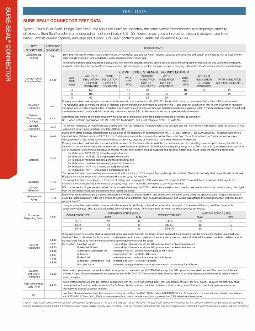
TEST DATA
SURE-SEAL® CONNECTOR TEST DATA
TEST REFERENCEREQUIREMENTS
DESCRIPTION PARAGRAPH
Environmental Sealing 3.5.1 Sure-Seal® connectors when mated shall form an environmental seal against water, moisture, aqueous solutions, oils and certain chemicals as well as dust and dirt
Tests include immersion in 3 feet depth in water solution containing 5% salt.
Contact Tensile Strength – Crimp 3.6.12
The minimum tensile load required to separate the wire from the contact, either by pulling the wire out of the crimp joint or breaking the wire within the crimp joint, shall not be less than the applicable limits as specified. Wire breakage, or contact damage not due to crimping, at less than tensile loads shall not constitute failure.
CRIMP TENSILE STRENGTH, POUNDS MINIMUMWIRE SIZE AWG
WITHOUT INSULATION SUPPORT
CONTACTS
WITH INSULATION SUPPORT
CONTACTS
WIRE SIZE AWG
WITHOUT INSULATION SUPPORT
CONTACTS
WITH INSULATION SUPPORT
CONTACTS
WIRE SIZE AWG
WITHOUT INSULATION SUPPORT
CONTACTS
WITH INSULATION SUPPORT CONTACTS
4 140 - 10 80 - 18 25 256 100 - 14 35 35 20 - 208 90 - 16 35 35 - - -
Insulation Resistance 4.4.1
Properly assembled and mated connectors shall be tested in accordance with MIL-STD-202, Method 302, except a potential of 500 ± 15 volt DC shall be used. The resistance shall be measured between adjacent parts of contacts (or cowntacts to ground for SS-1) and shall not be less than 100 M. If the specimen has been immersed in fluid in the preceding test, it shall be placed wet on a conducting surface and insulation resistance measured within 5 minutes between each contact and also between each contact and the conducting surface (except for SS-1 to be measured contact to ground while immersed).
Dielectric Withstanding
Voltage 4.4.22 Assembled and mated connectors shall show no evidence of breakdown between adjacent contacts (or contact to ground for
SS-1) when tested in accordance with MIL-STD-202, Method 301, and a test voltage of 1200 ± 15 volts AC.
Contact Resistance 4.4.3 The contact resistance of mated contacts shall be such that the resistance measured across the contacts and 5/8” behind the crimp junction shall not exceed 10 mΩ.
Test current to be 1 amp, and MIL-STD-202, Method 307.
Shock 4.4.4Mated connectors properly mounted shall be subjected to the shock test in accordance with MIL-STD- 202, Method 213B, CONDITION B. The shock test shall be repeated three (3) times in each of X, Y & Z axis. Suitable means shall be employed to monitor the current flow. Current discontinuity of 1 microsecond or more, disengagement of the mated connectors, evidence of cracking, breaking or loosening of parts shall be cause for rejection.
Vibration4.4.5
Properly assembled and mated connectors shall be mounted to the vibration table, with the wire leads strapped to a vibrating member approximately 3 inches from each end of the connector body and vibrated with a peak-to-peak amplitude of .25 inch across a frequency range of 5 to 39Hz, and a ±20g acceleration across 39 to 55 Hz, swept up in one minute and down in another minute. The vibration shall be swept up and down for a total of 36 hours under the following conditions:
Six (6) hours at 180°F (82°C) along the longitudinal axis Six (6) hours at 180°F (82°C) along a perpendicular axis Six (6) hours at room temperature along the longitudinal axis Six (6) hours at room temperature along a perpendicular axis Six (6) hours at -40°F (-40°C) along the longitudinal axis Six (6) hours at -40°F (-40°C) along a perpendicular axis
The connectors shall be connected in a series circuit with a minimum of 0.1 ampere flowing through the contacts. Electrical continuity shall be continually monitored. Breaks in continuity longer than one microsecond shall be cause for rejection.
Durability 4.4.6 The connectors shall be subjected to 25 cycles of mating and unmating at -10°C and another 25 cycles at 50°C. There shall be no evidence of damage to the contacts, the contact plating, the insulators or sealing rings, which would be detrimental to connector function.
Contact Retention 4.4.7 With the connector plug or receptacle held firmly, an axial dead weight of 7.5 lbs. shall be imposed on each wire for one minute without the contacts being dislodged
from the connector. Plugs and receptacles to be tested separately.
Maintenance Aging 4.4.8
Each wired receptacle and plug shall be subjected to 5 cycles of contact insertion and extraction in the same cavity using the approved tools. Plug and receptacle are to be tested separately. After the 5 cycles of insertion and extraction, each plug and receptacle in turn will be subjected to the contact retention test of 6 lbs. per paragraph 4.4.7.
Connector Separating Force 4.4.11
Using an assembled and mated connector with the receptacle held firmly by the wires, a load shall be applied to the wires of the plug until the connector is completely separated. The rate of loading shall be one inch per minute. The sample shall fall within the limits specified as follows:
CONNECTOR SIZE UNMATING FORCE (LBS.) CONNECTOR SIZE UNMATING FORCE (LBS.)MAX. MIN. MAX. MIN.
SS-1 12 6 SS-4 20 9SS-2 15 6 SS-5/7 30 10SS-3 18 8 SS-8/10 55 10
Solvent Resistance
4.4.134.4.144.4.154.4.164.4.174.4.184.4.19
Wired and mated connectors shall be subjected to the applicable fluids for the length of time specified. Following the test the connectors shall be immersed to a depth of 3 feet in salt water for 24 hours at room temperature. At the completion of the salt water immersion test and while still immersed insulation resistance shall be measured. Failure to meet the insulation resistance requirements shall be cause for rejection. Gasoline Splash 1 second dip - 3 minute air dry for 80 cycles at room ambient temperature.
Diesel Fuel Splash 1 second dip - 3 minute air dry for 80 cycles at room ambient temperature.Automotive Lubricating Oil Immersed in S.A.E. 30 weight lubricating oil for 1 hour.Antifreeze Immersed at 120°F (49°C) for 48 hours.Brake Fluid Immersed at room ambient temperature for 24 hours.Automatic Transmission Fluid Immersed at 120°F (49°C) for 48 hours.Gasoline Vapor Immersed in a gasoline vapor atmosphere at room temperature for 48 hours
Weather and Ozone Resistance
4.4.20Wired and properly mated connectors shall be subjected to ozone test per ASTMD-1149 except that 100 ppm of ozones shall be used. The duration of the test shall be 7 days. Outdoor exposure to be conducted per ASTM D-1171. The connector shall show no cracking or other degradation which would result in loss of sealing integrity.
High Temperature Long-Term 4.4.23
Wired mated connectors shall be tested in accordance with MIL-STD-202 Method 108A, Test Condition D at 105°C for 1000 hours. Following the test, they shall be subjected to 3 feet salt water immersion for 24 hours. While immersed, insulation resistance shall be determined. Failure to meet the insulation resistance requirements shall be cause for rejection.
UV - Sure Seal Connections has recently completed testing of the Sure Seal PVC Nitrile material (SM 3400-06) for UV resistance. The material was tested in accordance with ASTM G-26 (Xenon Arc), 720 hours exposure with no loss in tensile strength and greater than 75% retention of elongation.
Caution: “Sure-Seal® connectors are rated for use between temperatures of -40 to + 105 degrees Celsius. However, if a Sure-Seal® connector is exposed for long periods of time to temperatures exceeding 85 degrees Celsius and is unmated, it may lose its environmental sealing integrity upon remating. Thus, we recommend that both the plug and receptacle be replaced if environmental sealing is required after remating.”
Typical: Power Sure-Seal®, Flange Sure-Seal®, and Mini Sure-Seal® are essentially the same except for mechanical and amperage capacity differences. Sure-Seal® products are designed to meet specification CS-155. Items of most general interest to users and designers are listed below. With its current capability and large size, Power Sure-Seal® contacts and currents are covered in CS-169.