Sure Coat Rack-Mount Automatic Control Unit
70
Sure Coat r Rack-Mount Automatic Gun Control Unit Customer Product Manual Part 303818E Issued 6/02 NORDSON CORPORATION • AMHERST, OHIO • USA
Transcript of Sure Coat Rack-Mount Automatic Control Unit
Sure Coat� Rack-Mount Automatic Gun Control Unit
Customer Product ManualPart 303818E
Issued 6/02
NORDSON CORPORATION • AMHERST, OHIO • USA

Part 303818E � 2002 Nordson Corporation
Nordson Corporation welcomes requests for information, comments, and inquiries about its products. General informationabout Nordson can be found on the Internet using the following address: http://www.nordson.com.
Address all correspondence to:
Nordson CorporationAttn: Customer Service
555 Jackson StreetAmherst, OH 44001
Notice
This is a Nordson Corporation publication which is protected by copyright. Original copyright date 1998.No part of this document may be photocopied, reproduced, or translated to another language without the prior written
consent of Nordson Corporation. The information contained in this publication is subject to change without notice.
2002 All rights reserved.
Trademarks
AccuJet, AeroCharge, AquaGuard, Asymtek, Automove, Autotech, Baitgun, Blue Box, CF, CanWorks, Century,Clean Coat, CleanSleeve, CleanSpray, Control Coat, Cross-Cut, Cyclo-Kinetic, Dispensejet, DispenseMate, Durafiber,
Durasystem, Easy Coat, Easymove Plus, Econo-Coat, EFD, ETI, Excel 2000, Flex-O-Coat, FlexiCoat, Flexi-Spray,Flow Sentry, Fluidmove, FoamMelt, FoamMix, Helix, Horizon, Hot Shot, Isocoil, Isocore, Iso-Flo, JR, KB30, Kinetix,
Little Squirt, Magnastatic, MEG, Meltex, Microcoat, MicroSet, Millennium, Mini Squirt, Moist-Cure, Mountaingate,MultiScan, Nordson, OmniScan, OptiMix, Package of Values, Patternview, PluraFoam, Porous Coat, PowderGrid,Powderware, Prism, Pro-Flo, ProLink, Pro-Meter, Pro-Stream, PRX, RBX, Rhino, S. design stylized, Saturn, SC5,
Seal Sentry, Select Charge, Select Coat, Select Cure, Slautterback, Smart-Coat, Solder Plus, Spectrum, Spray Squirt,Spraymelt, Super Squirt, Sure Coat, Tela-Therm, Trends, Tribomatic, UniScan, UpTime, Veritec, Versa-Coat,
Versa-Screen, Versa-Spray, Walcom, Watermark, and When you expect more.are registered trademarks of Nordson Corporation.
ATS, Auto-Flo, AutoScan, BetterBook, Chameleon, CanNeck, Check Mate, Colormax, Control Weave,Controlled Fiberization, CoolWave, CPX, Dura-Coat, Dry Cure, E-Nordson, EasyClean, Eclipse, Equi=Bead, Fill Sentry,
Fillmaster, Gluie, Heli-flow, Ink-Dot, Iso-Flex, Lacquer Cure, Maxima, MicroFin, MicroMax, Minimeter, Multifil, Origin,PermaFlo, PluraMix, Powder Pilot, Powercure, Primarc, Process Sentry, PurTech, Pulse Spray, Ready Coat, Select Series,
Sensomatic, Shaftshield, SheetAire, Spectral, Spectronic, Speedking, Spray Works, Summit, Sure Brand, Sure Clean,Sure Max, Swirl Coat, Tempus, Tracking Plus, Trade Plus, Universal, Vista, Web Cure, and 2 Rings (Design)
are trademarks of Nordson Corporation.
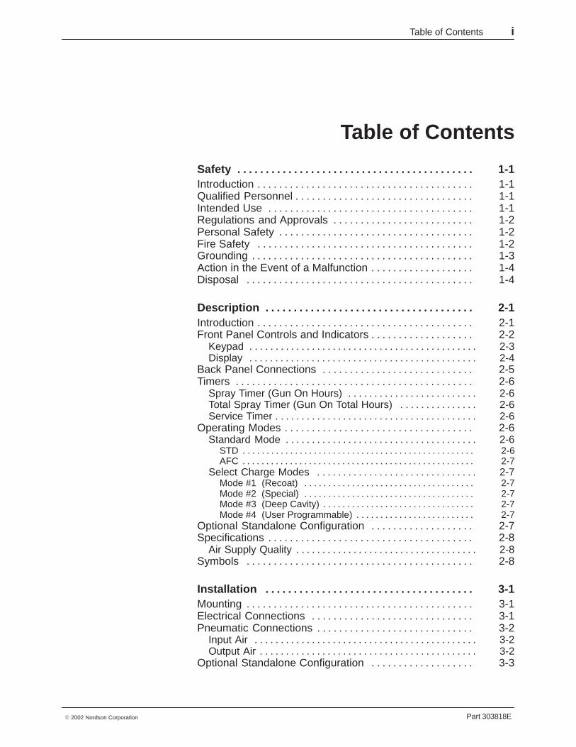
Table of Contents i
Part 303818E� 2002 Nordson Corporation
Table of Contents
Safety 1-1. . . . . . . . . . . . . . . . . . . . . . . . . . . . . . . . . . . . . . . . . . Introduction 1-1. . . . . . . . . . . . . . . . . . . . . . . . . . . . . . . . . . . . . . . . Qualified Personnel 1-1. . . . . . . . . . . . . . . . . . . . . . . . . . . . . . . . . Intended Use 1-1. . . . . . . . . . . . . . . . . . . . . . . . . . . . . . . . . . . . . . Regulations and Approvals 1-2. . . . . . . . . . . . . . . . . . . . . . . . . . Personal Safety 1-2. . . . . . . . . . . . . . . . . . . . . . . . . . . . . . . . . . . . Fire Safety 1-2. . . . . . . . . . . . . . . . . . . . . . . . . . . . . . . . . . . . . . . . Grounding 1-3. . . . . . . . . . . . . . . . . . . . . . . . . . . . . . . . . . . . . . . . . Action in the Event of a Malfunction 1-4. . . . . . . . . . . . . . . . . . . Disposal 1-4. . . . . . . . . . . . . . . . . . . . . . . . . . . . . . . . . . . . . . . . . .
Description 2-1. . . . . . . . . . . . . . . . . . . . . . . . . . . . . . . . . . . . . Introduction 2-1. . . . . . . . . . . . . . . . . . . . . . . . . . . . . . . . . . . . . . . . Front Panel Controls and Indicators 2-2. . . . . . . . . . . . . . . . . . .
Keypad 2-3. . . . . . . . . . . . . . . . . . . . . . . . . . . . . . . . . . . . . . . . . . . . Display 2-4. . . . . . . . . . . . . . . . . . . . . . . . . . . . . . . . . . . . . . . . . . . .
Back Panel Connections 2-5. . . . . . . . . . . . . . . . . . . . . . . . . . . . Timers 2-6. . . . . . . . . . . . . . . . . . . . . . . . . . . . . . . . . . . . . . . . . . . .
Spray Timer (Gun On Hours) 2-6. . . . . . . . . . . . . . . . . . . . . . . . . Total Spray Timer (Gun On Total Hours) 2-6. . . . . . . . . . . . . . . Service Timer 2-6. . . . . . . . . . . . . . . . . . . . . . . . . . . . . . . . . . . . . . .
Operating Modes 2-6. . . . . . . . . . . . . . . . . . . . . . . . . . . . . . . . . . . Standard Mode 2-6. . . . . . . . . . . . . . . . . . . . . . . . . . . . . . . . . . . . .
STD 2-6. . . . . . . . . . . . . . . . . . . . . . . . . . . . . . . . . . . . . . . . . . . . . . . . . AFC 2-7. . . . . . . . . . . . . . . . . . . . . . . . . . . . . . . . . . . . . . . . . . . . . . . . .
Select Charge Modes 2-7. . . . . . . . . . . . . . . . . . . . . . . . . . . . . . . Mode #1 (Recoat) 2-7. . . . . . . . . . . . . . . . . . . . . . . . . . . . . . . . . . . . Mode #2 (Special) 2-7. . . . . . . . . . . . . . . . . . . . . . . . . . . . . . . . . . . . Mode #3 (Deep Cavity) 2-7. . . . . . . . . . . . . . . . . . . . . . . . . . . . . . . . Mode #4 (User Programmable) 2-7. . . . . . . . . . . . . . . . . . . . . . . . .
Optional Standalone Configuration 2-7. . . . . . . . . . . . . . . . . . . Specifications 2-8. . . . . . . . . . . . . . . . . . . . . . . . . . . . . . . . . . . . . .
Air Supply Quality 2-8. . . . . . . . . . . . . . . . . . . . . . . . . . . . . . . . . . . Symbols 2-8. . . . . . . . . . . . . . . . . . . . . . . . . . . . . . . . . . . . . . . . . .
Installation 3-1. . . . . . . . . . . . . . . . . . . . . . . . . . . . . . . . . . . . . Mounting 3-1. . . . . . . . . . . . . . . . . . . . . . . . . . . . . . . . . . . . . . . . . . Electrical Connections 3-1. . . . . . . . . . . . . . . . . . . . . . . . . . . . . . Pneumatic Connections 3-2. . . . . . . . . . . . . . . . . . . . . . . . . . . . .
Input Air 3-2. . . . . . . . . . . . . . . . . . . . . . . . . . . . . . . . . . . . . . . . . . . Output Air 3-2. . . . . . . . . . . . . . . . . . . . . . . . . . . . . . . . . . . . . . . . . .
Optional Standalone Configuration 3-3. . . . . . . . . . . . . . . . . . .
Table of Contentsii
Part 303818E � 2002 Nordson Corporation
Operation 4-1. . . . . . . . . . . . . . . . . . . . . . . . . . . . . . . . . . . . . . . Introduction 4-1. . . . . . . . . . . . . . . . . . . . . . . . . . . . . . . . . . . . . . . . Startup 4-1. . . . . . . . . . . . . . . . . . . . . . . . . . . . . . . . . . . . . . . . . . . Initial Gun Usage 4-4. . . . . . . . . . . . . . . . . . . . . . . . . . . . . . . . . . .
Configuring Gun Type—Only for Software Versions 3.0 and 4.0 4-4. . . . . . . . . . . . . . . . Gun Current Baseline 4-4. . . . . . . . . . . . . . . . . . . . . . . . . . . . . . .
Operating Modes 4-5. . . . . . . . . . . . . . . . . . . . . . . . . . . . . . . . . . Standard Operating Mode 4-5. . . . . . . . . . . . . . . . . . . . . . . . . . . . Select Charge Modes—Software Version 4.0 4-6. . . . . . . . . . Select Charge Modes—Software Versions 3.0 and 2.0 4-7. . Select Charge Modes—Software Version 1.0 4-8. . . . . . . . . . Select Charge Mode Examples 4-9. . . . . . . . . . . . . . . . . . . . . . .
Air Pressure Adjustments 4-9. . . . . . . . . . . . . . . . . . . . . . . . . . . Flow Rate Air Pressure 4-9. . . . . . . . . . . . . . . . . . . . . . . . . . . . . . Atomizing Air Pressure 4-9. . . . . . . . . . . . . . . . . . . . . . . . . . . . . .
Error Conditions 4-10. . . . . . . . . . . . . . . . . . . . . . . . . . . . . . . . . . . . Shutdown 4-11. . . . . . . . . . . . . . . . . . . . . . . . . . . . . . . . . . . . . . . . . Optional Standalone Configuration 4-11. . . . . . . . . . . . . . . . . . . Daily Maintenance 4-12. . . . . . . . . . . . . . . . . . . . . . . . . . . . . . . . . .
Troubleshooting 5-1. . . . . . . . . . . . . . . . . . . . . . . . . . . . . . . . Introduction 5-1. . . . . . . . . . . . . . . . . . . . . . . . . . . . . . . . . . . . . . . . Diagnostics Mode 5-2. . . . . . . . . . . . . . . . . . . . . . . . . . . . . . . . . .
Entering Diagnostics Mode 5-2. . . . . . . . . . . . . . . . . . . . . . . . . . . Diagnostic Sequence 5-3. . . . . . . . . . . . . . . . . . . . . . . . . . . . . . . . . .
Error Codes 5-4. . . . . . . . . . . . . . . . . . . . . . . . . . . . . . . . . . . . . . . Determining Software Version 5-5. . . . . . . . . . . . . . . . . . . . . . . .
No Display when Powered Up 5-6. . . . . . . . . . . . . . . . . . . . . . . Checking Electrical Circuits 5-7. . . . . . . . . . . . . . . . . . . . . . . . . . Wiring Diagram 5-8. . . . . . . . . . . . . . . . . . . . . . . . . . . . . . . . . . . .
Repair 6-1. . . . . . . . . . . . . . . . . . . . . . . . . . . . . . . . . . . . . . . . . . Keypad Module Replacement 6-1. . . . . . . . . . . . . . . . . . . . . . . dc Power Supply Board Replacement 6-3. . . . . . . . . . . . . . . . . Manifold Assembly Replacement 6-4. . . . . . . . . . . . . . . . . . . . . Solenoid Valve Rebuild 6-6. . . . . . . . . . . . . . . . . . . . . . . . . . . . . Regulator/Gauge Replacement 6-7. . . . . . . . . . . . . . . . . . . . . .

Table of Contents iii
Part 303818E� 2002 Nordson Corporation
Parts 7-1. . . . . . . . . . . . . . . . . . . . . . . . . . . . . . . . . . . . . . . . . . . Introduction 7-1. . . . . . . . . . . . . . . . . . . . . . . . . . . . . . . . . . . . . . .
Using the Illustrated Parts List 7-1. . . . . . . . . . . . . . . . . . . . . . . Control Unit Illustrations 7-2. . . . . . . . . . . . . . . . . . . . . . . . . . . . . Two-Gauge Control Units 7-4. . . . . . . . . . . . . . . . . . . . . . . . . . . .
Single Two-Gauge Control Units 7-4. . . . . . . . . . . . . . . . . . . . . . Dual Two-Gauge Control Units 7-5. . . . . . . . . . . . . . . . . . . . . . . .
Three-Gauge Control Units 7-6. . . . . . . . . . . . . . . . . . . . . . . . . . Single Three-Gauge Control Units 7-6. . . . . . . . . . . . . . . . . . . . Dual Three-Gauge Control Units 7-7. . . . . . . . . . . . . . . . . . . . . .
Regulator Modules 7-8. . . . . . . . . . . . . . . . . . . . . . . . . . . . . . . . . Two-Gauge Regulator Module 7-8. . . . . . . . . . . . . . . . . . . . . . . . Three-Gauge Regulator Module 7-8. . . . . . . . . . . . . . . . . . . . . .
Pneumatic Modules 7-9. . . . . . . . . . . . . . . . . . . . . . . . . . . . . . . . Two-Gauge Pneumatic Module 7-9. . . . . . . . . . . . . . . . . . . . . . . Three-Gauge Pneumatic Module 7-10. . . . . . . . . . . . . . . . . . . . . .
Power Supply Module 7-12. . . . . . . . . . . . . . . . . . . . . . . . . . . . . . Keypad Module 7-14. . . . . . . . . . . . . . . . . . . . . . . . . . . . . . . . . . . . Solenoid Valve Kits 7-15. . . . . . . . . . . . . . . . . . . . . . . . . . . . . . . . .
Trigger Valve 7-15. . . . . . . . . . . . . . . . . . . . . . . . . . . . . . . . . . . . . . . F1/F2 Valve 7-16. . . . . . . . . . . . . . . . . . . . . . . . . . . . . . . . . . . . . . . .
Jumper Harness 7-16. . . . . . . . . . . . . . . . . . . . . . . . . . . . . . . . . . .

Table of Contentsiv
Part 303818E � 2002 Nordson Corporation

Safety 1-1
Part 303818E� 2002 Nordson Corporation
Section 1Safety
IntroductionRead and follow these safety instructions. Task- and equipment-specificwarnings, cautions, and instructions are included in equipmentdocumentation where appropriate.
Make sure all equipment documentation, including these instructions, isaccessible to all persons operating or servicing equipment.
Qualified PersonnelEquipment owners are responsible for making sure that Nordson equipmentis installed, operated, and serviced by qualified personnel. Qualifiedpersonnel are those employees or contractors who are trained to safelyperform their assigned tasks. They are familiar with all relevant safety rulesand regulations and are physically capable of performing their assignedtasks.
Intended UseUse of Nordson equipment in ways other than those described in thedocumentation supplied with the equipment may result in injury to personsor damage to property.
Some examples of unintended use of equipment include
� using incompatible materials
� making unauthorized modifications
� removing or bypassing safety guards or interlocks
� using incompatible or damaged parts
� using unapproved auxiliary equipment
� operating equipment in excess of maximum ratings

Safety1-2
Part 303818E � 2002 Nordson Corporation
Regulations and ApprovalsMake sure all equipment is rated and approved for the environment in whichit is used. Any approvals obtained for Nordson equipment will be voided ifinstructions for installation, operation, and service are not followed.
All phases of equipment installation must comply with all federal, state, andlocal codes.
Personal SafetyTo prevent injury follow these instructions.
� Do not operate or service equipment unless you are qualified.
� Do not operate equipment unless safety guards, doors, or covers areintact and automatic interlocks are operating properly. Do not bypass ordisarm any safety devices.
� Keep clear of moving equipment. Before adjusting or servicing anymoving equipment, shut off the power supply and wait until theequipment comes to a complete stop. Lock out power and secure theequipment to prevent unexpected movement.
� Relieve (bleed off) hydraulic and pneumatic pressure before adjusting orservicing pressurized systems or components. Disconnect, lock out,and tag switches before servicing electrical equipment.
� Obtain and read Material Safety Data Sheets (MSDS) for all materialsused. Follow the manufacturer’s instructions for safe handling and useof materials, and use recommended personal protection devices.
� To prevent injury, be aware of less-obvious dangers in the workplacethat often cannot be completely eliminated, such as hot surfaces, sharpedges, energized electrical circuits, and moving parts that cannot beenclosed or otherwise guarded for practical reasons.
Fire SafetyTo avoid a fire or explosion, follow these instructions.
� Do not smoke, weld, grind, or use open flames where flammablematerials are being used or stored.
� Provide adequate ventilation to prevent dangerous concentrations ofvolatile materials or vapors. Refer to local codes or your material MSDSfor guidance.
� Do not disconnect live electrical circuits while working with flammablematerials. Shut off power at a disconnect switch first to preventsparking.
Safety 1-3
Part 303818E� 2002 Nordson Corporation
� Know where emergency stop buttons, shutoff valves, and fireextinguishers are located. If a fire starts in a spray booth, immediatelyshut off the spray system and exhaust fans.
� Clean, maintain, test, and repair equipment according to the instructionsin your equipment documentation.
� Use only replacement parts that are designed for use with originalequipment. Contact your Nordson representative for parts informationand advice.
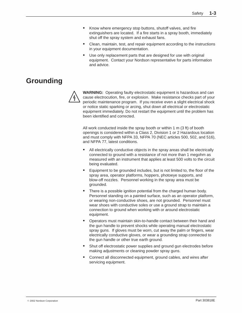
Grounding
WARNING: Operating faulty electrostatic equipment is hazardous and cancause electrocution, fire, or explosion. Make resistance checks part of yourperiodic maintenance program. If you receive even a slight electrical shockor notice static sparking or arcing, shut down all electrical or electrostaticequipment immediately. Do not restart the equipment until the problem hasbeen identified and corrected.
All work conducted inside the spray booth or within 1 m (3 ft) of boothopenings is considered within a Class 2, Division 1 or 2 Hazardous locationand must comply with NFPA 33, NFPA 70 (NEC articles 500, 502, and 516),and NFPA 77, latest conditions.
� All electrically conductive objects in the spray areas shall be electricallyconnected to ground with a resistance of not more than 1 megohm asmeasured with an instrument that applies at least 500 volts to the circuitbeing evaluated.
� Equipment to be grounded includes, but is not limited to, the floor of thespray area, operator platforms, hoppers, photoeye supports, andblow-off nozzles. Personnel working in the spray area must begrounded.
� There is a possible ignition potential from the charged human body.Personnel standing on a painted surface, such as an operator platform,or wearing non-conductive shoes, are not grounded. Personnel mustwear shoes with conductive soles or use a ground strap to maintain aconnection to ground when working with or around electrostaticequipment.
� Operators must maintain skin-to-handle contact between their hand andthe gun handle to prevent shocks while operating manual electrostaticspray guns. If gloves must be worn, cut away the palm or fingers, wearelectrically conductive gloves, or wear a grounding strap connected tothe gun handle or other true earth ground.
� Shut off electrostatic power supplies and ground gun electrodes beforemaking adjustments or cleaning powder spray guns.
� Connect all disconnected equipment, ground cables, and wires afterservicing equipment.

Safety1-4
Part 303818E � 2002 Nordson Corporation
Action in the Event of a MalfunctionIf a system or any equipment in a system malfunctions, shut off the systemimmediately and perform the following steps:
� Disconnect and lock out electrical power. Close pneumatic shutoffvalves and relieve pressures.
� Identify the reason for the malfunction and correct it before restarting theequipment.
DisposalDispose of equipment and materials used in operation and servicingaccording to local codes.
Description 2-1
Part 303818E� 2002 Nordson Corporation
Section 2Description
IntroductionSure Coat automatic gun control units are used with automatic powderspray guns. The control units:
� control air pressure to the spray gun’s powder feed pump
� provide dc power to the spray gun’s voltage multiplier
� control the spray gun’s electrostatic output
� monitor the spray gun’s voltage and microamperage output
The control status information and parameters are adjusted and viewedfrom the front panel keypad and Liquid Crystal Display (LCD). The LCDdisplays operation mode, set point values, and spray gun output. The frontpanel keys allow the operator to choose between the different controlmodes and to set the electrostatic output levels.
The control unit is available in two-gauge and three-gauge, single and dualconfigurations. A single control unit services one powder spray gun, a dualcontrol unit services two powder spray guns.
Typically, several control units are mounted in a standard equipment rackand connected to a master control unit, which controls and distributes powerand air to the control units in the rack. The control unit can also be used asa standalone unit, without a master control unit.
Description2-2
Part 303818E � 2002 Nordson Corporation
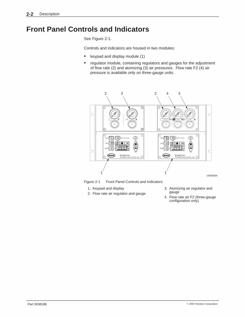
Front Panel Controls and IndicatorsSee Figure 2-1.
Controls and indicators are housed in two modules:
� keypad and display module (1)
� regulator module, containing regulators and gauges for the adjustmentof flow rate (2) and atomizing (3) air pressures. Flow rate F2 (4) airpressure is available only on three-gauge units.
1400560A
0 0 00 0
1
22 3 4 3
1
Figure 2-1 Front Panel Controls and Indicators
1. Keypad and display2. Flow rate air regulator and gauge
3. Atomizing air regulator andgauge
4. Flow rate air F2 (three-gaugeconfiguration only)
Description 2-3
Part 303818E� 2002 Nordson Corporation
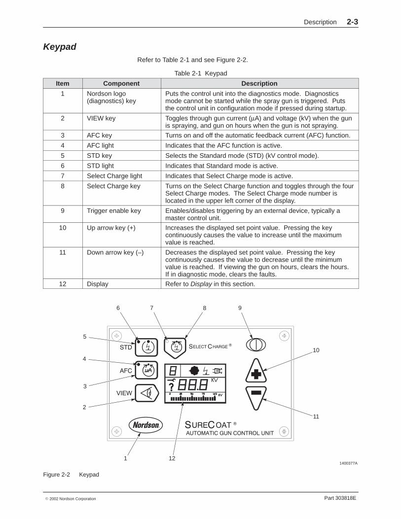
KeypadRefer to Table 2-1 and see Figure 2-2.
Table 2-1 Keypad
Item Component Description
1 Nordson logo(diagnostics) key
Puts the control unit into the diagnostics mode. Diagnosticsmode cannot be started while the spray gun is triggered. Putsthe control unit in configuration mode if pressed during startup.
2 VIEW key Toggles through gun current (µA) and voltage (kV) when the gunis spraying, and gun on hours when the gun is not spraying.
3 AFC key Turns on and off the automatic feedback current (AFC) function.
4 AFC light Indicates that the AFC function is active.
5 STD key Selects the Standard mode (STD) (kV control mode).
6 STD light Indicates that Standard mode is active.
7 Select Charge light Indicates that Select Charge mode is active.
8 Select Charge key Turns on the Select Charge function and toggles through the fourSelect Charge modes. The Select Charge mode number islocated in the upper left corner of the display.
9 Trigger enable key Enables/disables triggering by an external device, typically amaster control unit.
10 Up arrow key (+) Increases the displayed set point value. Pressing the keycontinuously causes the value to increase until the maximumvalue is reached.
11 Down arrow key (–) Decreases the displayed set point value. Pressing the keycontinuously causes the value to decrease until the minimumvalue is reached. If viewing the gun on hours, clears the hours.If in diagnostic mode, clears the faults.
12 Display Refer to Display in this section.
1400377A
2
3
4
6
5
1
87 9
10
11
12
Figure 2-2 Keypad

Description2-4
Part 303818E � 2002 Nordson Corporation
DisplayRefer to Table 2-2 and see Figure 2-3.
Table 2-2 Display
Item Component Description
1 Select Charge modenumber
Indicates which Select Charge mode is currently active. Modesare numbered 1 to 4.
2 F1/F2 Indicates the flow rate regulator selected.
3 Powder icon Indicates that the spray gun is triggered and air is flowing to thepowder feed pump. This icon will flash if an error is detected inthe solenoid circuit.
4 Digital display Displays set point and actual parameter information. May alsodisplay gun on hours, total hours, error codes, software version,kV set point, gun µA set point, and the gun µA actual value. Thedisplay is blank when no appropriate value can be displayed.
5 Gun kV or Electrostaticsicon
Lights to indicate that the spray gun is triggered. The icon willflash if an error is detected in the gun drive circuit.
6 Purge icon This function is not active in this control unit.
7 Unit indicator Lights to indicate the selection of kV, µA, HRS x10, and ALARM.
8 Bar graph units Shows the units being displayed by the bar graph.
9 Bar graph Shows the parameter displayed on the digital display as a bargraph. The bar graph is only active while the spray gun istriggered.
10 Fault icon Lights when there is an alarm or error condition. Clear a fault bycorrecting all errors or powering off control unit.
11 Diagnostics icon Lights when the control unit is in diagnostics mode.
1400378A
1 2 3 5 6
7
8
9
10
11
4
Figure 2-3 Display
Description 2-5
Part 303818E� 2002 Nordson Corporation
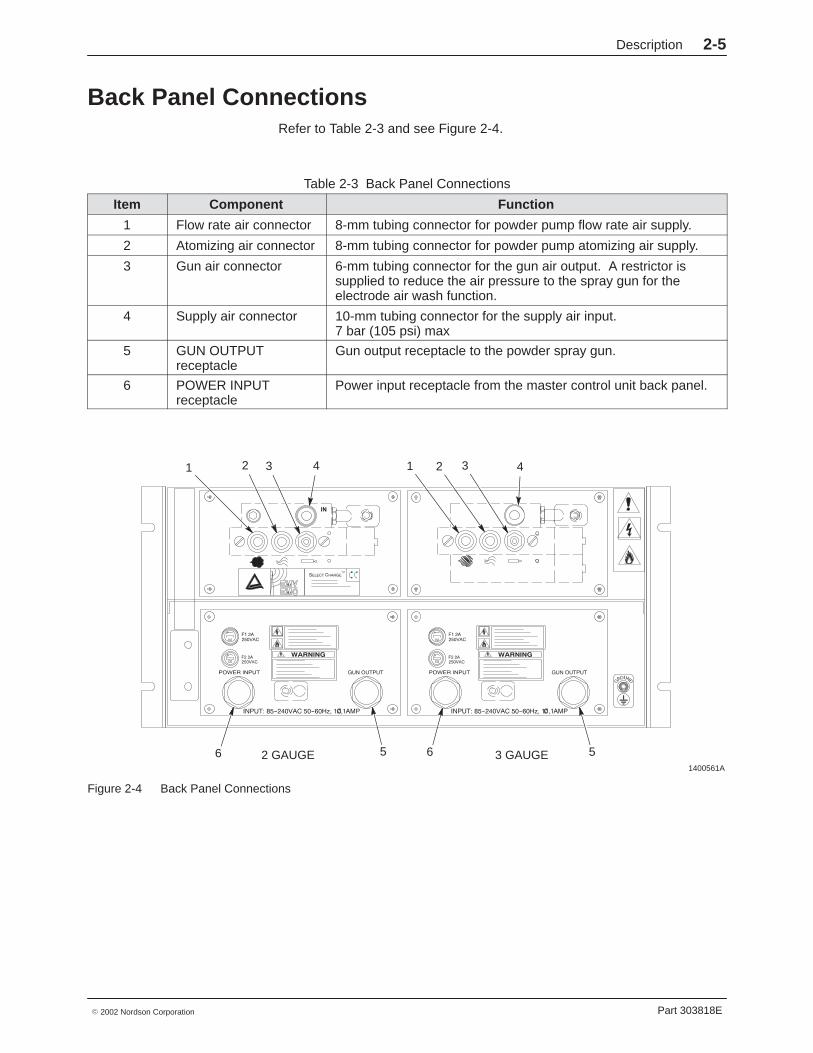
Back Panel ConnectionsRefer to Table 2-3 and see Figure 2-4.
Table 2-3 Back Panel Connections
Item Component Function
1 Flow rate air connector 8-mm tubing connector for powder pump flow rate air supply.
2 Atomizing air connector 8-mm tubing connector for powder pump atomizing air supply.
3 Gun air connector 6-mm tubing connector for the gun air output. A restrictor issupplied to reduce the air pressure to the spray gun for theelectrode air wash function.
4 Supply air connector 10-mm tubing connector for the supply air input.7 bar (105 psi) max
5 GUN OUTPUTreceptacle
Gun output receptacle to the powder spray gun.
6 POWER INPUTreceptacle
Power input receptacle from the master control unit back panel.
1400561A
1 2 3 4
6 5 6
1 2 3 4
2 GAUGE 3 GAUGE 5
Figure 2-4 Back Panel Connections
Description2-6
Part 303818E � 2002 Nordson Corporation
TimersThe timers available are the spray timer, the total spray timer, and theservice timer.
Spray Timer (Gun On Hours)The spray timer (gun on hours) keeps track of time the spray gun is on.Time is shown as hours (HRS). View by pressing the VIEW key when thespray gun is off. Reset by pressing the down arrow while viewing. Use thistimer to track preventive maintenance procedures.
Total Spray Timer (Gun On Total Hours)The total spray timer (gun on total hours) keeps track of the total time thespray gun has been on. Time is shown as HRS x 10. View by pressing theNordson logo key and going into the diagnostics mode. The numeral 1appears in the upper left corner of the display when the total spray timer isvisible. This timer cannot be reset. Use this timer for diagnostics.
Service TimerThe service timer (total hours) keeps track of the time the control unit hasbeen in service. Time is shown as HRS x 10. View by pressing theNordson logo key and going into the diagnostics mode. The numeral 2appears in the upper left corner of the display when the service timer isvisible. This timer cannot be reset. Use this timer for diagnostics.
Operating ModesOperating modes are Standard and Select Charge.
Standard ModeIn standard (STD) mode the operator can choose to set kV or maximumcurrent (µA) output.
STDSetting kV output provides maximum transfer efficiency when coating largeobjects with a gun-to-part distance of 0.2–0.3 m (8–12 in.).
To set kV, turn STD on and AFC off. Only the STD LED lights.
Description 2-7
Part 303818E� 2002 Nordson Corporation
AFCAutomatic feedback current (AFC) allows the operator to set the maximumcurrent (µA) output from the spray gun to prevent excess charging of thesprayed powder. This provides an optimum combination of kV andelectrostatic field strength for coating parts with interior corners and deeprecesses at close range.
To turn on AFC the control unit must be in standard mode (STD LED lit).When AFC is on both the STD and AFC LEDs are lit.
Select Charge ModesSelect Charge modes allow the operator to select different electrostaticcharging characteristics for an optimum coating on differently shaped parts.
Mode #1 (Recoat)This mode is for recoating. It is designed to delay back ionization and tominimize picture framing.
Mode #2 (Special)This mode is referred to as special or reinforcement mode and is typicallyapplied to selected spray guns in an automatic gun arrangement. Thismode may provide performance benefits in certain automatic coatingapplications.
Mode #3 (Deep Cavity)This mode is for deep cavities. It is designed to provide high transferefficiency inside deep cavities while minimizing back ionization on cavityedges.
Mode #4 (User Programmable)This mode allows the operator to set kV and µA for a particular powder orpart. The control unit stores the settings in memory and restores them eachtime mode 4 is selected.
Optional Standalone ConfigurationThe Sure Coat automatic control unit can be converted to operate as astandalone unit. The standalone unit does not need to be mounted in arack or connected to a master control unit. Refer to the Installation sectionfor conversion information.
Description2-8
Part 303818E � 2002 Nordson Corporation
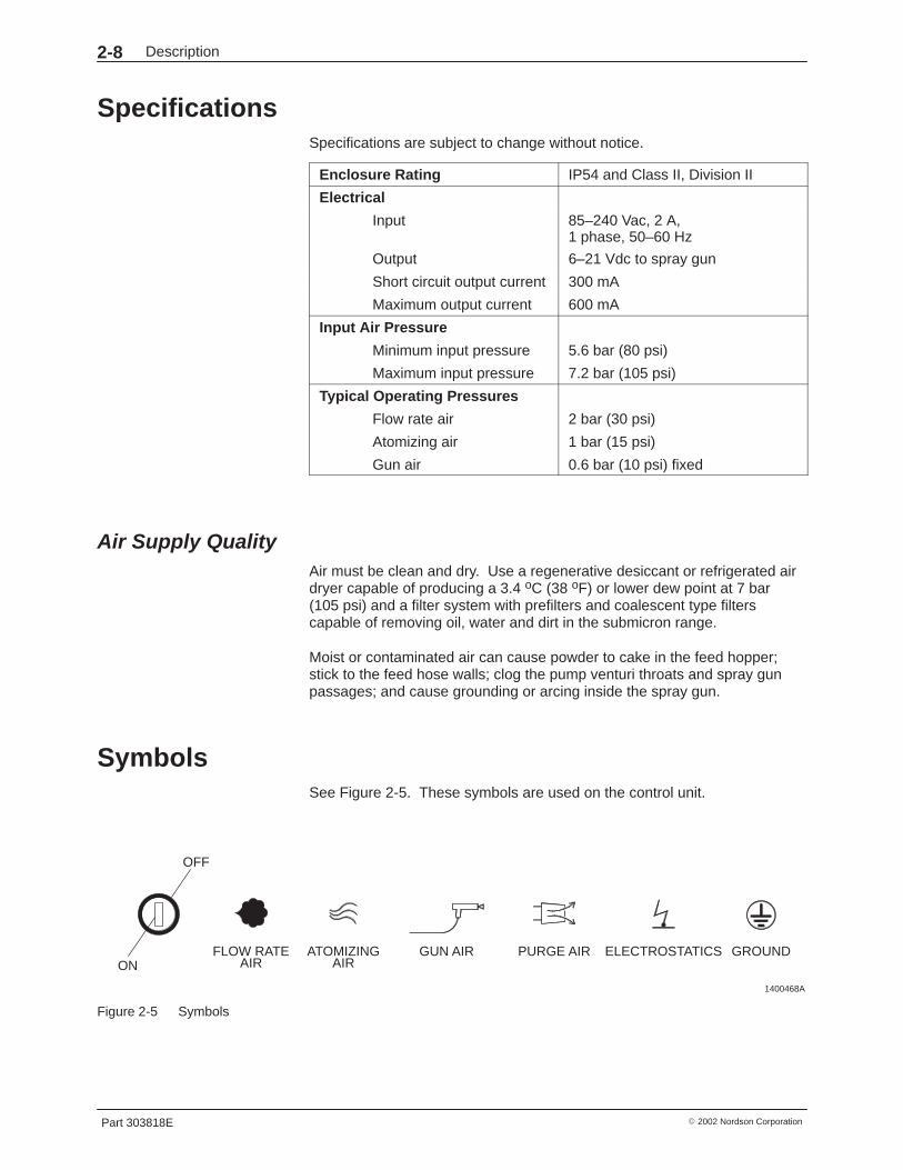
SpecificationsSpecifications are subject to change without notice.
Enclosure Rating IP54 and Class II, Division II
Electrical
Input 85–240 Vac, 2 A,1 phase, 50–60 Hz
Output 6–21 Vdc to spray gun
Short circuit output current 300 mA
Maximum output current 600 mA
Input Air Pressure
Minimum input pressure 5.6 bar (80 psi)
Maximum input pressure 7.2 bar (105 psi)
Typical Operating Pressures
Flow rate air 2 bar (30 psi)
Atomizing air 1 bar (15 psi)
Gun air 0.6 bar (10 psi) fixed
Air Supply QualityAir must be clean and dry. Use a regenerative desiccant or refrigerated airdryer capable of producing a 3.4 oC (38 oF) or lower dew point at 7 bar(105 psi) and a filter system with prefilters and coalescent type filterscapable of removing oil, water and dirt in the submicron range.
Moist or contaminated air can cause powder to cake in the feed hopper;stick to the feed hose walls; clog the pump venturi throats and spray gunpassages; and cause grounding or arcing inside the spray gun.
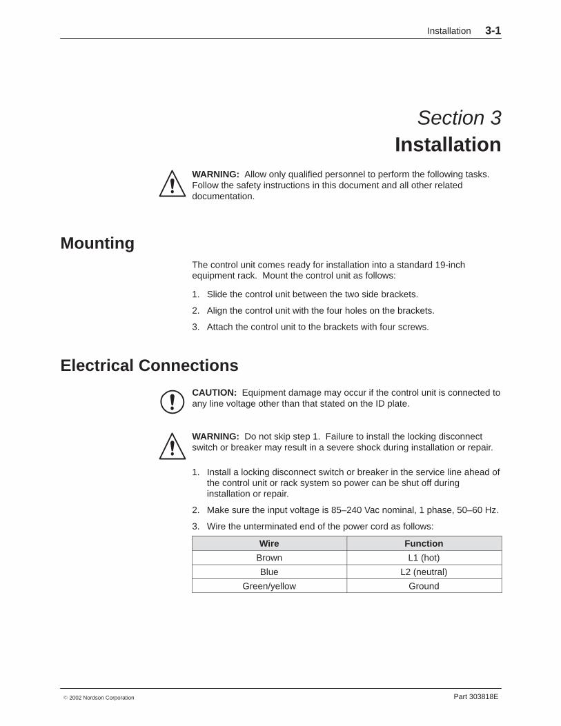
SymbolsSee Figure 2-5. These symbols are used on the control unit.
1400468A
OFF
ONFLOW RATE
AIRATOMIZING
AIRGUN AIR PURGE AIR ELECTROSTATICS GROUND
Figure 2-5 Symbols
Installation 3-1
Part 303818E� 2002 Nordson Corporation
Section 3Installation
WARNING: Allow only qualified personnel to perform the following tasks.Follow the safety instructions in this document and all other relateddocumentation.
MountingThe control unit comes ready for installation into a standard 19-inchequipment rack. Mount the control unit as follows:
1. Slide the control unit between the two side brackets.
2. Align the control unit with the four holes on the brackets.
3. Attach the control unit to the brackets with four screws.
Electrical Connections
CAUTION: Equipment damage may occur if the control unit is connected toany line voltage other than that stated on the ID plate.
WARNING: Do not skip step 1. Failure to install the locking disconnectswitch or breaker may result in a severe shock during installation or repair.
1. Install a locking disconnect switch or breaker in the service line ahead ofthe control unit or rack system so power can be shut off duringinstallation or repair.
2. Make sure the input voltage is 85–240 Vac nominal, 1 phase, 50–60 Hz.
3. Wire the unterminated end of the power cord as follows:
Wire Function
Brown L1 (hot)
Blue L2 (neutral)
Green/yellow Ground
Installation3-2
Part 303818E � 2002 Nordson Corporation
Electrical Connections (contd)
WARNING: All electrically conductive equipment in the spray area must begrounded. Ungrounded or poorly grounded equipment can store anelectrostatic charge which can give personnel a severe shock or arc andcause a fire or explosion.
4. Connect the ground strap furnished with the control unit to the groundstud on the cabinet.
5. Secure the clamp to a true earth ground.
6. Connect the gun cable to the GUN OUTPUT receptacle.
Pneumatic ConnectionsMaximum input air pressure is 7 bar (105 psi). The supply air must be cleanand dry. Moist or contaminated air can cause powder to cake in the feedhopper, stick to the feed hose walls, clog the pump venturi throats and spraygun passages, and cause grounding or arcing inside the spray gun.
Use prefilters and coalescent filters with automatic drains and a refrigeratedor regenerative desiccant air dryer capable of producing a 3.4 �C (38 �F) orlower dewpoint at 7 bar (105 psi).
See Figure 2-4 for pneumatic connections.
Input Air1. Install a manually operated, self-relieving shutoff valve in the supply line
to the control unit or rack system.
2. Connect 10-mm tubing from the air supply to the connector markedIN (4) on the pneumatic panel. In a rack system, air is typically suppliedto the control units through a manifold mounted in the bottom of therack.
Output Air1. Connect 8-mm blue tubing to the atomizing air connector (2) on the
pneumatic panel. Route this tubing to the connector marked A(atomizing air) on the spray gun’s powder pump.
2. Connect 8-mm black tubing to the flow rate air connector (1) on thepneumatic panel. Route this tubing to the connector marked F (flow rateair) on the powder pump.
3. If used, connect 6-mm gun air tubing from the spray gun to the gun airconnector (3).
Installation 3-3
Part 303818E� 2002 Nordson Corporation
Optional Standalone Configuration Follow these procedures to convert the standard Sure Coat control unit to astandalone unit.
WARNING: Fire detection and conveyor interlocks must interrupt ac powerto all Sure Coat automatic control units to prevent serious damage or fire.
WARNING: Shut down and lock out the main power supply beforeremoving any enclosure panels. Failure to observe this warning may resultin a severe shock.
See Figure 3-1.
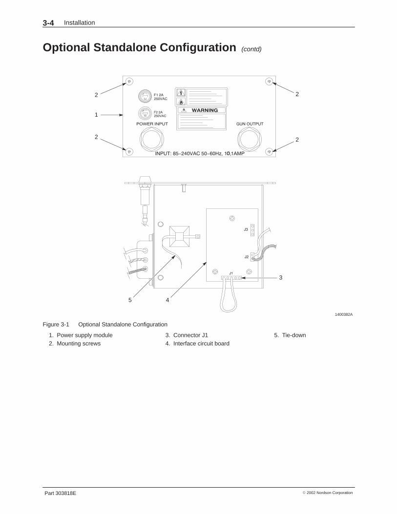
1. Remove the four mounting screws (2) from the power supplymodule (1). Carefully slide out the module out of the enclosure.
2. Locate the interface circuit board (4) on the back of the power supplytray. Remove the harness from connector J1 (3).
3. Remove the jumper harness from the tie-down (5).
4. Install the jumper harness in connector J1.
NOTE: A jumper harness is shipped with the control unit. If you need toorder a new one, refer to the Parts section of this manual.
5. Carefully install the power supply tray into the enclosure and secure itwith the four mounting screws.
NOTE: If you are converting a dual unit, steps 1–4 must be completed foreach power supply module. One jumper harness is required for each.
WARNING: All electrically conductive equipment in the spray area must begrounded. Ungrounded or poorly grounded equipment can store anelectrostatic charge which can give personnel a severe shock or arc andcause a fire or explosion.
6. Connect the control unit to a true earth ground.
7. After you start up the control unit, perform the Optional StandaloneConfiguration procedure in the Operation section.
Installation3-4
Part 303818E � 2002 Nordson Corporation
Optional Standalone Configuration (contd)
1400382A
1
2
3
4
2
22
5
Figure 3-1 Optional Standalone Configuration
1. Power supply module2. Mounting screws
3. Connector J14. Interface circuit board
5. Tie-down

Operation 4-1
Part 303818E� 2002 Nordson Corporation
Section 4Operation
WARNING: Allow only qualified personnel to perform the following tasks.Follow the safety instructions in this document and all other relateddocumentation.
Introduction
WARNING: This equipment can be dangerous unless it is used inaccordance with the rules laid down in this manual.
WARNING: All electrically conductive equipment in the spray area must begrounded. Ungrounded or poorly grounded equipment can store anelectrostatic charge which can give personnel a severe shock or arc andcause a fire or explosion.
This section explains basic operation procedures for the Sure Coatautomatic control unit. Before operating a Nordson powder spray system,read all system component manuals.
Startup Perform the following procedure to start up the control unit.
1. Make sure that the following conditions are met before starting up thecontrol unit. Refer to the system component manuals for startupinstructions.
� The booth exhaust fans are turned on.
� The powder recovery system is operating.
� The powder in the feed hopper is thoroughly fluidized.
� The gun cable, powder feed hose, and air tubing are correctlyconnected to the spray gun, powder pump, and control unit.
Operation4-2
Part 303818E � 2002 Nordson Corporation
Startup (contd)
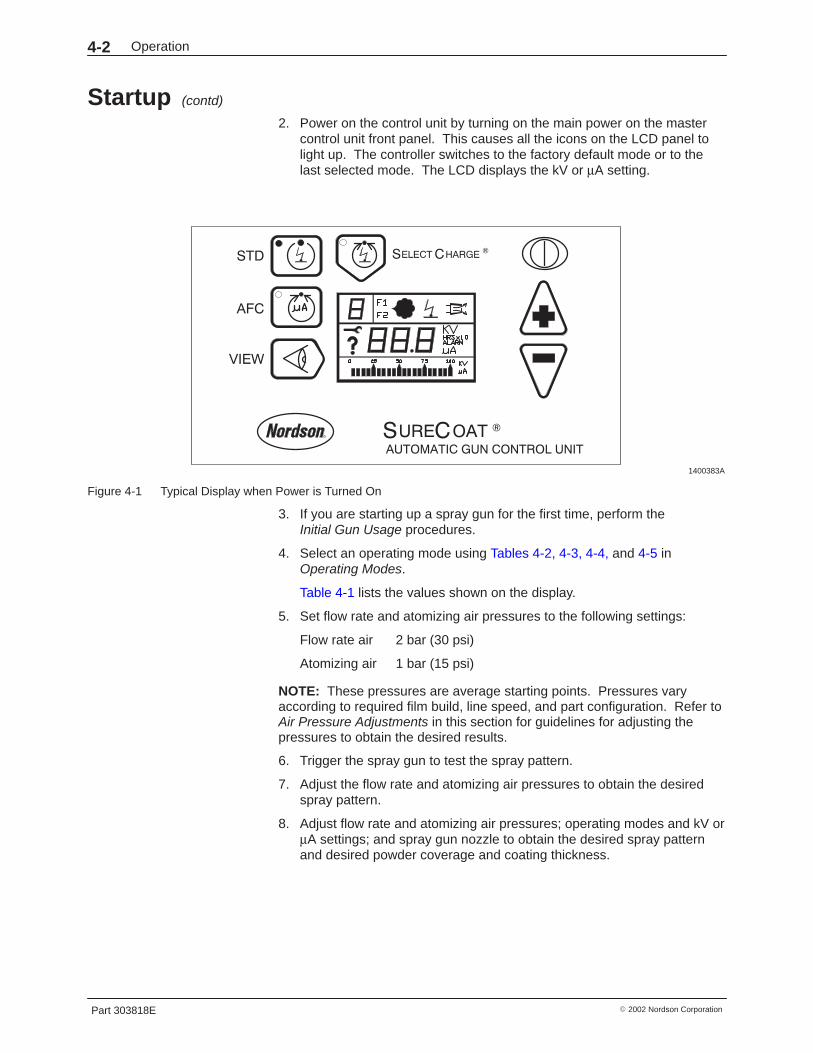
2. Power on the control unit by turning on the main power on the mastercontrol unit front panel. This causes all the icons on the LCD panel tolight up. The controller switches to the factory default mode or to thelast selected mode. The LCD displays the kV or µA setting.
1400383A
Figure 4-1 Typical Display when Power is Turned On
3. If you are starting up a spray gun for the first time, perform the Initial Gun Usage procedures.
4. Select an operating mode using Tables 4-2, 4-3, 4-4, and 4-5 inOperating Modes.
Table 4-1 lists the values shown on the display.
5. Set flow rate and atomizing air pressures to the following settings:
Flow rate air 2 bar (30 psi)
Atomizing air 1 bar (15 psi)
NOTE: These pressures are average starting points. Pressures varyaccording to required film build, line speed, and part configuration. Refer toAir Pressure Adjustments in this section for guidelines for adjusting thepressures to obtain the desired results.
6. Trigger the spray gun to test the spray pattern.
7. Adjust the flow rate and atomizing air pressures to obtain the desiredspray pattern.
8. Adjust flow rate and atomizing air pressures; operating modes and kV orµA settings; and spray gun nozzle to obtain the desired spray patternand desired powder coverage and coating thickness.

Operation 4-3
Part 303818E� 2002 Nordson Corporation
Obtaining a high quality finish and maximum transfer efficiency (percentageof powder sprayed that adheres to the part) requires experimentation andexperience. Settings for electrostatic voltage and air pressure affect overallcoating performance. In most applications, the settings should produce asoft spray pattern that directs as much of the powder as possible onto thepart with a minimum of overspray. These settings allow the maximumamount of charged powder to be attracted to the grounded part.
Lowering the voltage is a common method for trying to improve coverage ofdeep recesses and interior corners of parts. However, lowering the voltagemay also reduce the overall transfer efficiency. Powder velocity, direction,and pattern shape can be just as important as electrostatic voltage incoating these areas.
Refer to Operating Modes for suggested kV or µA settings, and Air PressureAdjustments for guidelines on flow rate and atomizing air pressure settings.
Table 4-1 Displays
Function Display when gun triggered(1) Display when gun not triggered
STD Mode & Viewing kV Version 1.0, 2.0, and 4.0:kV set point
Version 3.0:Actual kV
kV setting
AFC On & Viewing kV Actual kV Initial kV setting (factory kV)
AFC On & Viewing µA Actual µA(2) AFC set point(3)
AFC Off & Viewing kV kV set point kV set point
AFC Off & Viewing µA Actual µA Blank(1) Use the VIEW key to toggle the display between kV and µA values. The units are shown on the displayand the bar graph.(2) Pressing the AFC key shows the AFC set point then the actual µA current feedback from the spray gunon the display and the bar graph.(3) Pressing the up or down key switches the display to AFC set point. All subsequent key presseschange the AFC set point.
Operation4-4
Part 303818E � 2002 Nordson Corporation
Initial Gun UsageWhen a spray gun is first put into service, perform the Configuring Gun Typeand Gun Current Baseline procedures. You do not need to perform theseprocedures again unless you connect a new spray gun to the control unit.
Configuring Gun Type—Only for Software Versions 3.0 and 4.0The default spray gun type is the Sure Coat powder spray gun. Perform thefollowing procedure to switch between Sure Coat and Versa-Spray powderspray guns.
1. Depress and hold the Nordson logo key and turn on the control unit.
2. Hold the Nordson logo key until CFG appears on the display. CHOOSEGUN scrolls across the display.
3. Either press the VIEW key or wait until SC appears on the display.
4. Use the arrow keys to select either Sure Coat (SC) or Versa-Spray (VS).
5. Press the Nordson logo key to exit the CONFIG mode.
Gun Current Baseline 1. Turn on the master control unit, or if the control unit is a standalone unit
turn on electrical power to the unit.
2. Make sure the control unit is in STD mode, AFC off, with the maximumkV set point displayed.Sure Coat guns: 95kV, Versa-Spray guns: 100 kV
3. Press the VIEW key to display µA.
4. On the master control unit, use the trigger switch to select the controlunit, move the keyswitch to READY, and press the trigger enable key.
5. Adjust the flow rate and the atomizing air pressure to obtain the desiredspray pattern.
6. Record the µA output with no parts in front of the spray gun.
Monitor the µA output daily, under the same conditions. A significantincrease in µA output indicates a probable short in the gun resistor. Asignificant decrease indicates a failing resistor or voltage multiplier.
Operation 4-5
Part 303818E� 2002 Nordson Corporation
Operating Modes
Standard Operating Mode
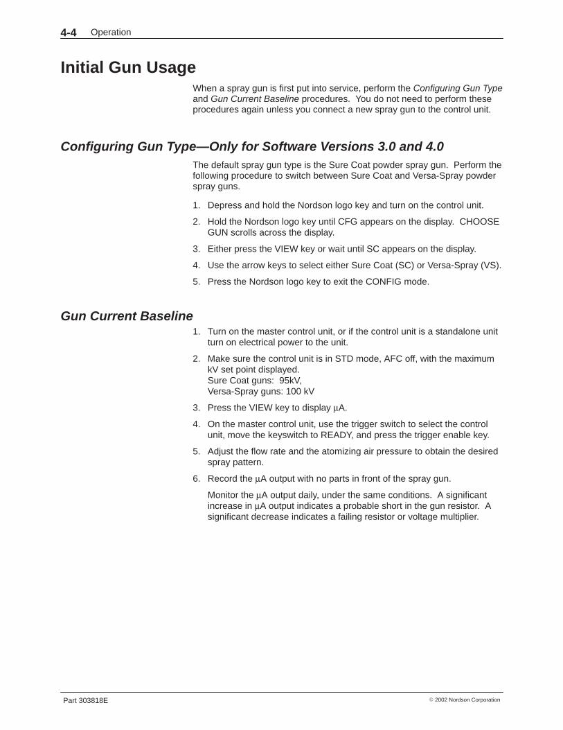
Table 4-2 Standard Operating Mode
Mode AFC Description
Standard Off See Figure 4-2. Use the up/down arrow keys to turn adjust the kV set point.The control unit stores the kV setting when the mode is changed or when thecontrol unit is powered off.
Setting Sure Coat Gun Versa-Spray Gun
kV Set Point adjustable adjustable
kV Range 0 then 25 to 95 kV 0 then 25 to 100 kV
Maximum kVOutput/Default Setting
95 kV 100 kV
On See Figure 4-2. Use the up/down arrow keys to turn adjust the AFC set point.The control unit stores the AFC setting when the mode is changed or when thecontrol unit is powered off.
Voltage is automatically set to the maximum, and AFC allows the setting of afeedback current threshold. If the current threshold is reached, the voltage isautomatically adjusted to maintain the required coverage.
If the AFC set point is changed, the controller remembers the new set point.
Setting Sure Coat Gun Versa-Spray Gun
Initial kV Value 95 kV (not adjustable) 100 kV (not adjustable)
Set Point Increments 5 µA 5 µA
kV Range 10 to 100 µA 10 to 120 µA
Default Set Point 30 µA(Default for version 1.0: 20 µA)
Maximum Current 100 µA 120 µA
1400470A
Figure 4-2 STD Mode with AFC On
Operation4-6
Part 303818E � 2002 Nordson Corporation
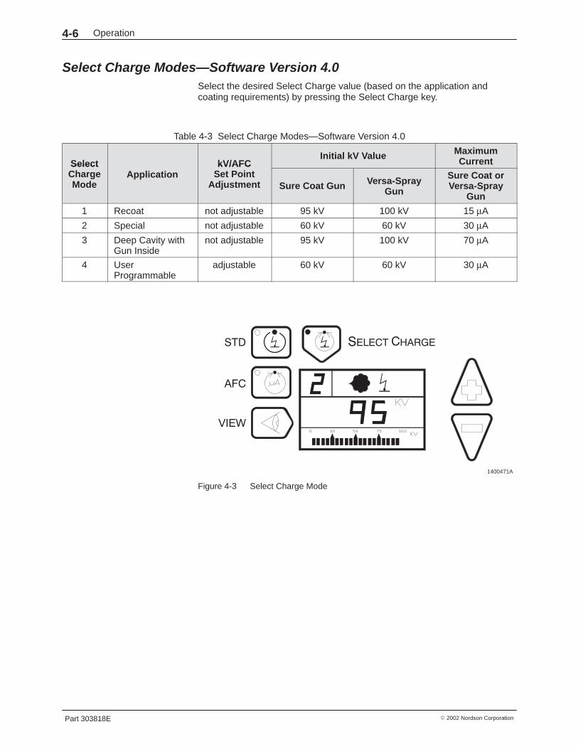
Select Charge Modes—Software Version 4.0 Select the desired Select Charge value (based on the application andcoating requirements) by pressing the Select Charge key.
Table 4-3 Select Charge Modes—Software Version 4.0
Select kV/AFCInitial kV Value Maximum
CurrentSelectChargeMode
ApplicationkV/AFC
Set PointAdjustment Sure Coat Gun Versa-Spray
Gun
Sure Coat orVersa-Spray
Gun
1 Recoat not adjustable 95 kV 100 kV 15 µA
2 Special not adjustable 60 kV 60 kV 30 µA
3 Deep Cavity withGun Inside
not adjustable 95 kV 100 kV 70 µA
4 UserProgrammable
adjustable 60 kV 60 kV 30 µA
1400471A
Figure 4-3 Select Charge Mode
Operation 4-7
Part 303818E� 2002 Nordson Corporation
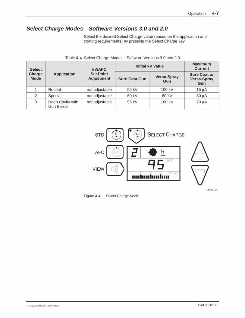
Select Charge Modes—Software Versions 3.0 and 2.0 Select the desired Select Charge value (based on the application andcoating requirements) by pressing the Select Charge key.
Table 4-4 Select Charge Modes—Software Versions 3.0 and 2.0
Select kV/AFCInitial kV Value Maximum
CurrentSelectChargeMode
ApplicationkV/AFC
Set PointAdjustment Sure Coat Gun Versa-Spray
Gun
Sure Coat orVersa-Spray
Gun
1 Recoat not adjustable 95 kV 100 kV 15 µA
2 Special not adjustable 60 kV 60 kV 30 µA
3 Deep Cavity withGun Inside
not adjustable 95 kV 100 kV 70 µA
1400471A
Figure 4-4 Select Charge Mode
Operation4-8
Part 303818E � 2002 Nordson Corporation
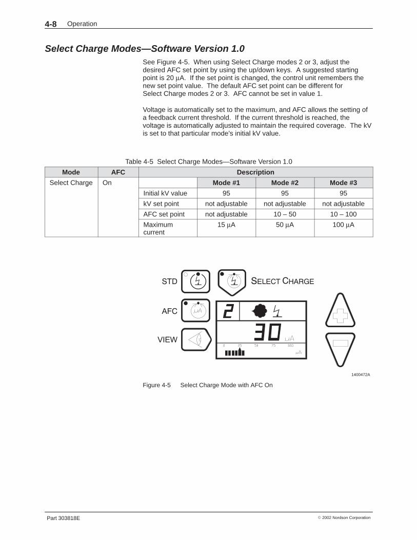
Select Charge Modes—Software Version 1.0 See Figure 4-5. When using Select Charge modes 2 or 3, adjust thedesired AFC set point by using the up/down keys. A suggested startingpoint is 20 µA. If the set point is changed, the control unit remembers thenew set point value. The default AFC set point can be different forSelect Charge modes 2 or 3. AFC cannot be set in value 1.
Voltage is automatically set to the maximum, and AFC allows the setting ofa feedback current threshold. If the current threshold is reached, thevoltage is automatically adjusted to maintain the required coverage. The kVis set to that particular mode’s initial kV value.
Table 4-5 Select Charge Modes—Software Version 1.0
Mode AFC Description
Select Charge On Mode #1 Mode #2 Mode #3g
Initial kV value 95 95 95
kV set point not adjustable not adjustable not adjustable
AFC set point not adjustable 10 – 50 10 – 100
Maximumcurrent
15 µA 50 µA 100 µA
1400472A
Figure 4-5 Select Charge Mode with AFC On
Operation 4-9
Part 303818E� 2002 Nordson Corporation
Select Charge Mode ExamplesMode Application
1 When recoating parts that have already been cured but require additional coating andcuring, the gun current should be limited and maintained.
2 When coating large parts with a mix of large flat sections and recessed or angledsections, high kV is required for painting the flat sections at a far gun to part distance, butlow voltage from the spray gun is required for painting the recessed sections at a closegun to part distance.
3 When coating parts with deep cavities, low kV and low current are required to coat thecorners, but high kV and high current are required to coat the flat sections inside.
4 Version 4.0 Only
For special applications, such as metallic powders or unique parts. To use, selectmode 4 and set the kV and µA. The control unit stores the settings and recalls them eachtime mode 4 is selected.
Air Pressure AdjustmentsRefer to the feed hopper manual for the recommended fluidizing airpressure and to Specifications in the Description section for recommendedflow rate and atomizing air pressures.
Flow Rate Air PressureFlow rate air transports a powder and air mixture from the feed hopper tothe spray gun. Increasing the flow rate air pressure increases the amountof powder sprayed from the spray gun and may increase the thickness ofthe powder deposited on the part.
If the flow rate air pressure is set too low, an inadequate film build or unevenpowder output may result. If the flow rate air pressure is too high, too muchpowder could be output at too high a velocity. This could cause excessivefilm build or overspray, which reduces transfer efficiency and wastespowder. Excessive flow rate air pressure may also accelerate the build-upof impact fused powder (impact fusion) in the spray gun or pump or causepremature wear of the spray gun and pump parts in contact with thepowder.
Keeping the amount of overspray to a minimum reduces the amount ofpowder to be recovered and recycled. This minimizes wear and tear on thesystem components such as pumps, spray guns, and filters. Maintenancecosts are also kept down.
Atomizing Air Pressure Atomizing air is added to the powder and air stream to increase the powdervelocity in the feed hose and break up clumps of powder. Higher atomizingair pressures are needed at lower powder flow rates to keep the powderparticles suspended in the air stream. Higher powder velocities may causethe spray pattern to change.
Operation4-10
Part 303818E � 2002 Nordson Corporation
Atomizing Air Pressure (contd)
If the atomizing air pressure is set too low, the result may be uneven powderoutput or puffing and surging from the spray gun. If set too high, atomizingair pressure can increase the powder velocity and cause excessiveoverspray, impact fusion, and premature wear of the pump and spray gunparts.
NOTE: Set the atomizing air to at least 0.3 bar (5 psi). If the air pressure istoo low, powder may flow back from the powder pump and get inside thecontrol unit, damaging the air valves and regulators.
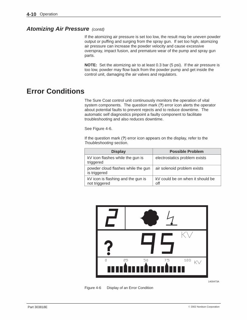
Error ConditionsThe Sure Coat control unit continuously monitors the operation of vitalsystem components. The question mark (?) error icon alerts the operatorabout potential faults to prevent rejects and to reduce downtime. Theautomatic self diagnostics pinpoint a faulty component to facilitatetroubleshooting and also reduces downtime.
See Figure 4-6.
If the question mark (?) error icon appears on the display, refer to theTroubleshooting section.
Display Possible Problem
kV icon flashes while the gun istriggered
electrostatics problem exists
powder cloud flashes while the gunis triggered
air solenoid problem exists
kV icon is flashing and the gun isnot triggered
kV could be on when it should beoff
1400473A
Figure 4-6 Display of an Error Condition
Operation 4-11
Part 303818E� 2002 Nordson Corporation
ShutdownTo shut down the control unit:
1. Turn off power to the control unit:
� If the control unit is connected to a master control unit, turn themaster control unit’s power switch to the off position.
� If the control unit is not connected to a master control unit, turn thecontrol unit’s power switch to the off position.
2. Ground the gun electrode to discharge any residual voltage.
3. Turn off main power on the master control unit front panel.
4. Perform the Daily Maintenance procedure in this section.
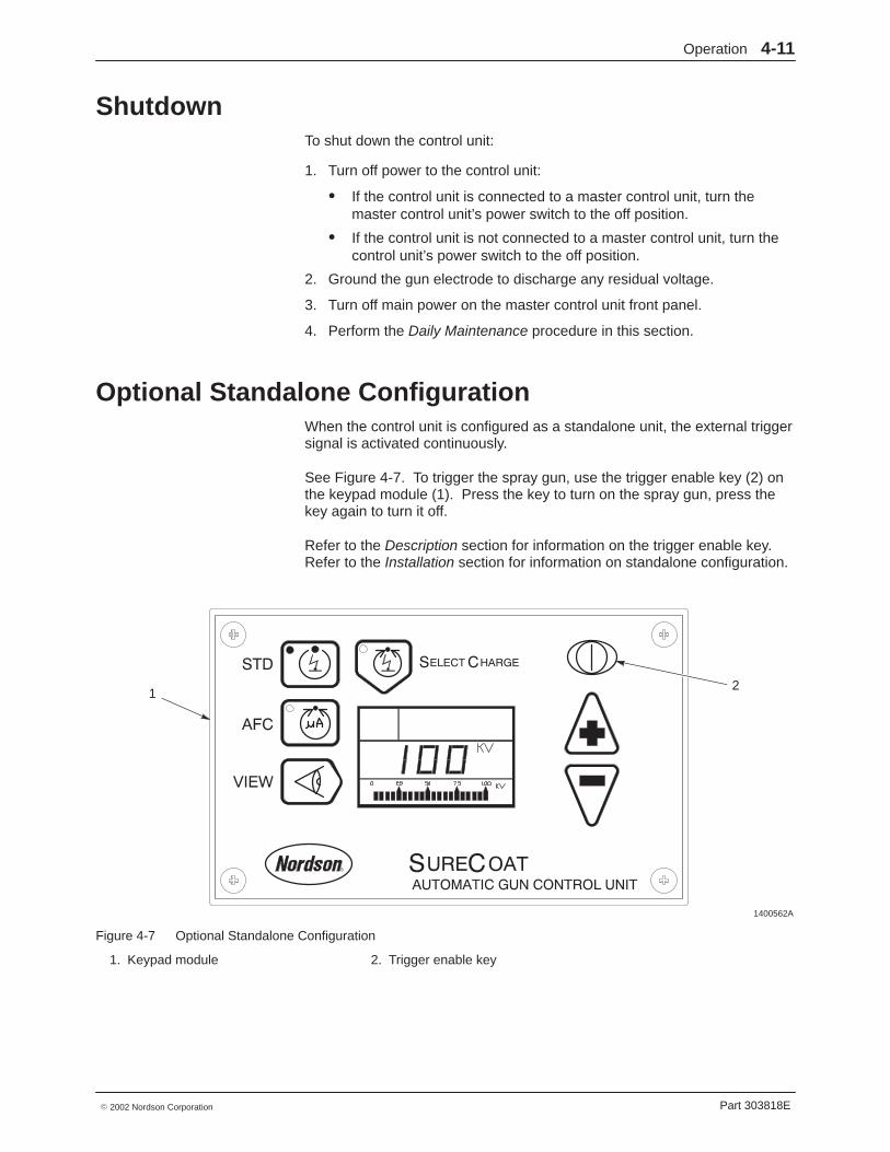
Optional Standalone ConfigurationWhen the control unit is configured as a standalone unit, the external triggersignal is activated continuously.
See Figure 4-7. To trigger the spray gun, use the trigger enable key (2) onthe keypad module (1). Press the key to turn on the spray gun, press thekey again to turn it off.
Refer to the Description section for information on the trigger enable key.Refer to the Installation section for information on standalone configuration.
1400562A
21
Figure 4-7 Optional Standalone Configuration
1. Keypad module 2. Trigger enable key

Operation4-12
Part 303818E � 2002 Nordson Corporation
Daily Maintenance
WARNING: Turn off the electrostatic voltage and ground the gun electrodebefore performing the following tasks. Failure to observe this warning couldresult in a severe shock.
1. Compare the spray gun’s µA output in kV mode with no parts in front ofthe spray gun with the output and kV setting recorded in the GunCurrent Baseline procedure. Significant differences may mean that thespray gun electrode assembly or multiplier is shorted or failed. Refer tothe Troubleshooting section for more information.
WARNING: Check all ground connections thoroughly. Ungroundedequipment and parts may accumulate a charge that could arc and cause afire or explosion. Failure to observe this warning could cause serious injuryor equipment and property damage.
2. Check all ground connections, including part grounds. Ungrounded orpoorly grounded parts affect transfer efficiency, electrostatic wrap, andthe quality of the finish.
3. Check power and spray gun cable connections.
4. Make sure that the air being supplied to the control unit is clean and dry.
5. Wipe powder and dust off the control unit cabinet with a clean, dry cloth.
6. Disassemble the spray guns and powder pumps and clean them. Referto the spray gun and pump manuals for instructions.

Troubleshooting 5-1
Part 303818E� 2002 Nordson Corporation
Section 5Troubleshooting
WARNING: Allow only qualified personnel to perform the following tasks.Follow the safety instructions in this document and all other relateddocumentation.
IntroductionThis section contains troubleshooting procedures. These procedures coveronly the most common problems that you may encounter. If you cannotsolve the problem with the information given here, contact your localNordson representative for help.
WARNING: Do not touch the spray gun if the kV icon is flashing. A flashingkV icon while the spray gun is not triggered is a warning to the operator thatvoltage may be present at the spray gun due to faulty hardware. Failure tocomply with this warning may result in an electrical shock.
Display Possible Problem
kV icon flashes while the gun istriggered
electrostatics problem exists
powder cloud flashes while the gunis triggered
air solenoid problem exists
kV icon is flashing and the gun isnot triggered
kV could be on when it should beoff
Error codes may only be viewed in diagnostic mode. Errors are not clearedby viewing the codes. To clear error codes, you must first fix the problem,then press the down arrow or turn off the control unit.

Troubleshooting5-2
Part 303818E � 2002 Nordson Corporation
Diagnostics ModeSee Figure 5-1.
If the spray gun is triggered while an error condition is present, a questionmark is displayed on the digital display and the powder and kV symbolsflash on and off. The diagnostics mode must be entered to correct theerrors.
1400473A
Figure 5-1 Display of an Error Condition
Entering Diagnostics ModeThe diagnostic function is available at all times. The spray gun may still betriggered while the display shows the diagnostics information.
NOTE: In software version 1.0, the diagnostics function is only availablewhen the system is not triggered. Triggering the spray gun or pressing theNordson key at any time while in diagnostics results in an automatic exitfrom the diagnostics mode and a return to the previous operating mode.
NOTE: Do not power off the control unit unless instructed to do so. Errorcodes are erased when the control unit is powered off.
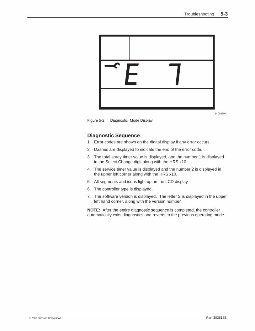
See Figure 5-2. Press and hold the Nordson logo key to enter thediagnostics mode.
In diagnostics mode, a wrench symbol is shown on the digital display.
When diagnostic mode is entered, the system performs internal checks andautomatically cycles through the following diagnostics sequence. Each setof information is displayed for several seconds.
NOTE: Record the error codes displayed during the diagnostic sequence.Refer to Error Codes in this section to identify the error code and correct theproblem.
Troubleshooting 5-3
Part 303818E� 2002 Nordson Corporation
1400389A
Figure 5-2 Diagnostic Mode Display
Diagnostic Sequence 1. Error codes are shown on the digital display if any error occurs.
2. Dashes are displayed to indicate the end of the error code.
3. The total spray timer value is displayed, and the number 1 is displayedin the Select Change digit along with the HRS x10.
4. The service timer value is displayed and the number 2 is displayed inthe upper left corner along with the HRS x10.
5. All segments and icons light up on the LCD display.
6. The controller type is displayed.
7. The software version is displayed. The letter S is displayed in the upperleft hand corner, along with the version number.
NOTE: After the entire diagnostic sequence is completed, the controllerautomatically exits diagnostics and reverts to the previous operating mode.
Troubleshooting5-4
Part 303818E � 2002 Nordson Corporation
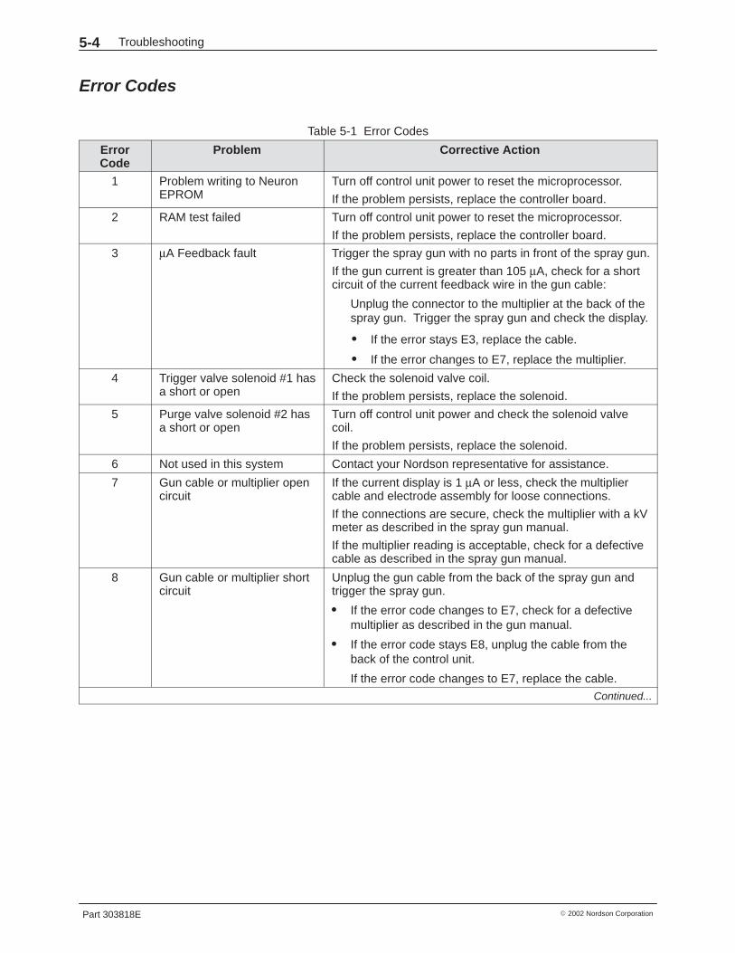
Error Codes
Table 5-1 Error Codes
ErrorCode
Problem Corrective Action
1 Problem writing to NeuronEPROM
Turn off control unit power to reset the microprocessor.
If the problem persists, replace the controller board.
2 RAM test failed Turn off control unit power to reset the microprocessor.
If the problem persists, replace the controller board.
3 µA Feedback fault Trigger the spray gun with no parts in front of the spray gun.
If the gun current is greater than 105 µA, check for a shortcircuit of the current feedback wire in the gun cable:
Unplug the connector to the multiplier at the back of thespray gun. Trigger the spray gun and check the display.
� If the error stays E3, replace the cable.
� If the error changes to E7, replace the multiplier.
4 Trigger valve solenoid #1 hasa short or open
Check the solenoid valve coil.
If the problem persists, replace the solenoid.
5 Purge valve solenoid #2 hasa short or open
Turn off control unit power and check the solenoid valvecoil.
If the problem persists, replace the solenoid.
6 Not used in this system Contact your Nordson representative for assistance.
7 Gun cable or multiplier opencircuit
If the current display is 1 µA or less, check the multipliercable and electrode assembly for loose connections.
If the connections are secure, check the multiplier with a kVmeter as described in the spray gun manual.
If the multiplier reading is acceptable, check for a defectivecable as described in the spray gun manual.
8 Gun cable or multiplier shortcircuit
Unplug the gun cable from the back of the spray gun andtrigger the spray gun.
� If the error code changes to E7, check for a defectivemultiplier as described in the gun manual.
� If the error code stays E8, unplug the cable from theback of the control unit.
If the error code changes to E7, replace the cable.Continued...

Troubleshooting 5-5
Part 303818E� 2002 Nordson Corporation
Corrective ActionProblemErrorCode
9 Not used in this system Contact your Nordson representative for assistance.
10 Not used in this system Contact your Nordson representative for assistance.
11 Controller board hardware Turn off control unit power.
Unplug the multiplier connection at the back of the spraygun.
Power up the controller and then trigger the spray gun.
If the problem changes to an open circuit, then the board isworking correctly. Check the multiplier.
If the problem persists, replace the controller board.
12 Not used in this system Contact your Nordson representative for assistance.
13 Not used in this system Contact your Nordson representative for assistance.
14 Not used in this system Contact your Nordson representative for assistance.
15 Foldback fault Unplug the gun cable from the back of the spray gun andtrigger the spray gun.
� If the error code changes to E7, check for a defectivemultiplier as described in the gun manual.
� If the error code stays E15, unplug the cable from theback of the control unit. If the error code changes to E7,replace the cable.
Determining Software VersionSee Figure 5-3.
The software version of your system is displayed during the diagnosticsmode. The letter S (software) appears in the upper left corner, the softwareversion is displayed next to the wrench symbol.
1400474A
Figure 5-3 Determining Software Version
Troubleshooting5-6
Part 303818E � 2002 Nordson Corporation
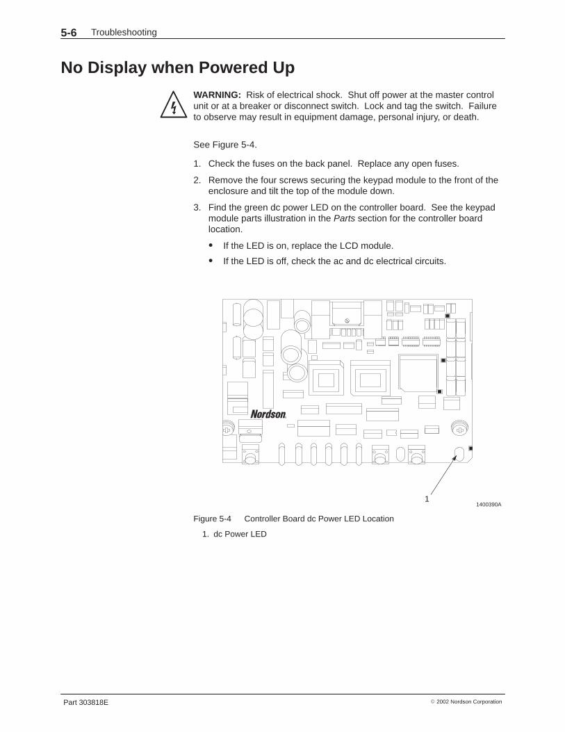
No Display when Powered Up
WARNING: Risk of electrical shock. Shut off power at the master controlunit or at a breaker or disconnect switch. Lock and tag the switch. Failureto observe may result in equipment damage, personal injury, or death.
See Figure 5-4.
1. Check the fuses on the back panel. Replace any open fuses.
2. Remove the four screws securing the keypad module to the front of theenclosure and tilt the top of the module down.
3. Find the green dc power LED on the controller board. See the keypadmodule parts illustration in the Parts section for the controller boardlocation.
� If the LED is on, replace the LCD module.
� If the LED is off, check the ac and dc electrical circuits.
1400390A1
Figure 5-4 Controller Board dc Power LED Location
1. dc Power LED

Troubleshooting 5-7
Part 303818E� 2002 Nordson Corporation
Checking Electrical Circuits
WARNING: Risk of electrical shock. Shut off power at the master controlunit or at a breaker or disconnect switch. Lock and tag the switch. Failureto observe may result in equipment damage, personal injury, or death.
See Figures 5-5 and 5-6.
1. Check the fuses (1 and 2) on the back panel (3). Replace any openfuses.
2. Check the ac wiring.
3. Check the dc outputs (5) at the dc power supply (4).
4. Tighten the connections at the dc power supply and the interfaceboard (6).
5. Check the connections at the ac power input (8) and the gun cableinput (7) on the back panel.
1400563A
3
4
1
8
7
5
6
2
Figure 5-5 Checking Electrical Circuits
1. Fuse 12. Fuse 23. Back panel4. Power supply
5. dc Output6. Interface board7. Gun cable input8. ac Power input
Troubleshooting5-8
Part 303818E � 2002 Nordson Corporation
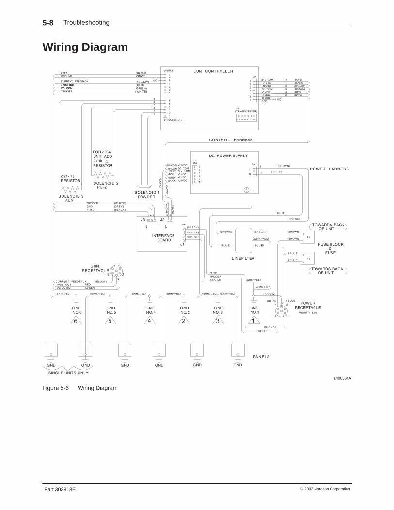
Wiring Diagram
1400564A
Figure 5-6 Wiring Diagram
Repair 6-1
Part 303818E� 2002 Nordson Corporation
Section 6Repair
WARNING: Allow only qualified personnel to perform the following tasks.Follow the safety instructions in this document and all other relateddocumentation.
WARNING: Disconnect and lock out electrical power before performing thefollowing tasks. Failure to observe this warning could result in personalinjury or death.
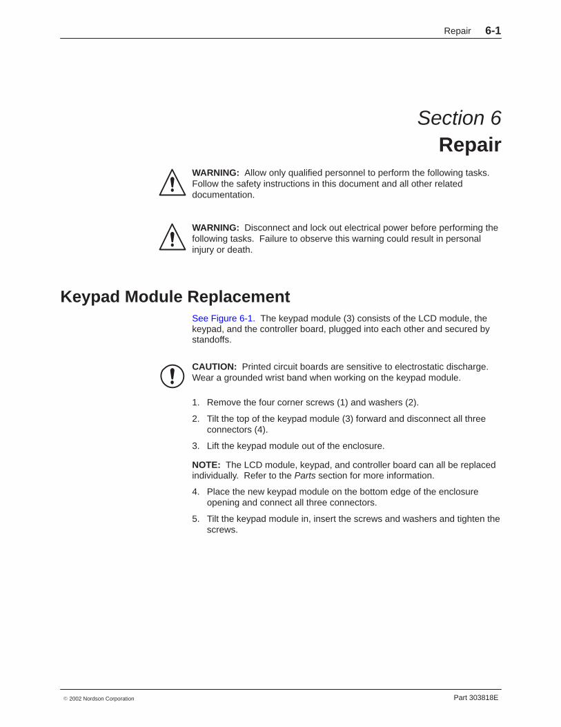
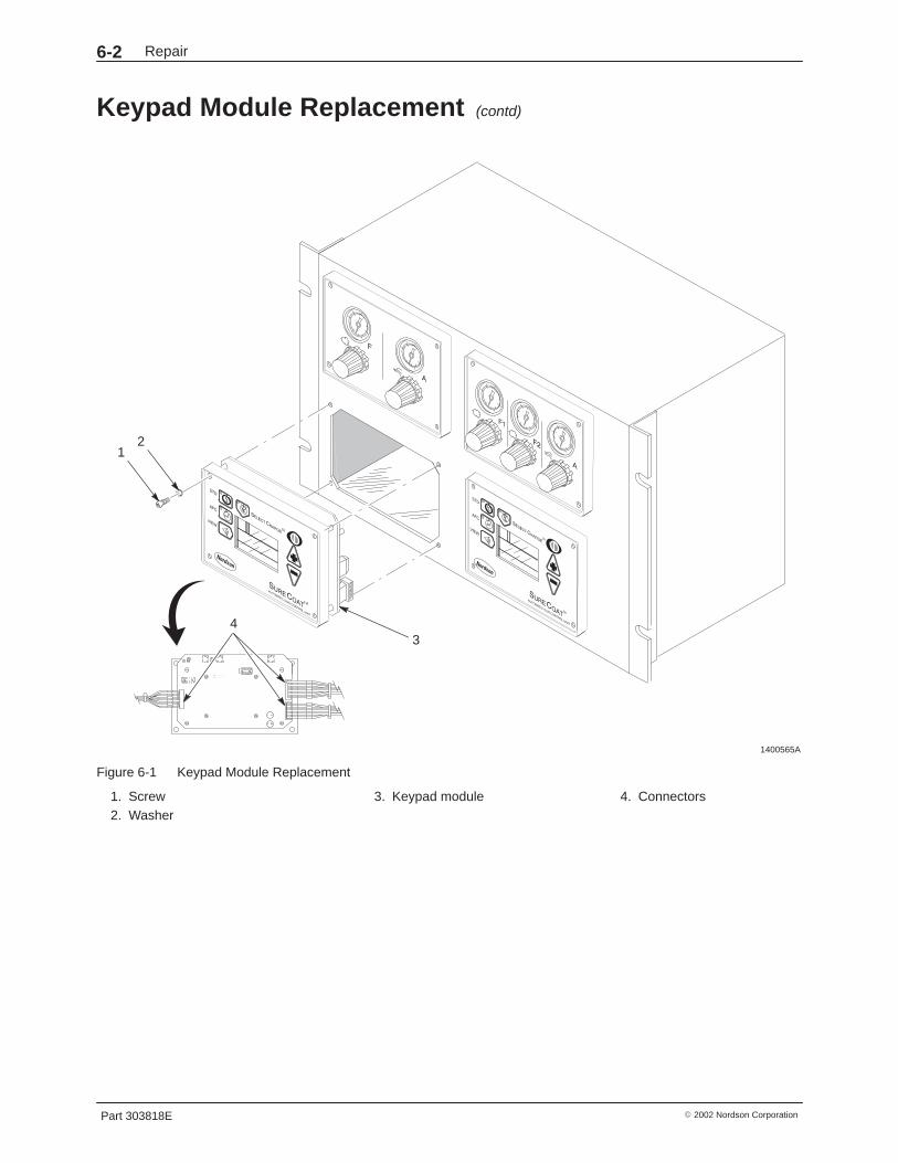
Keypad Module Replacement See Figure 6-1. The keypad module (3) consists of the LCD module, thekeypad, and the controller board, plugged into each other and secured bystandoffs.
CAUTION: Printed circuit boards are sensitive to electrostatic discharge.Wear a grounded wrist band when working on the keypad module.
1. Remove the four corner screws (1) and washers (2).
2. Tilt the top of the keypad module (3) forward and disconnect all threeconnectors (4).
3. Lift the keypad module out of the enclosure.
NOTE: The LCD module, keypad, and controller board can all be replacedindividually. Refer to the Parts section for more information.
4. Place the new keypad module on the bottom edge of the enclosureopening and connect all three connectors.
5. Tilt the keypad module in, insert the screws and washers and tighten thescrews.
Repair6-2
Part 303818E � 2002 Nordson Corporation
Keypad Module Replacement (contd)
1400565A
4
21
3
Figure 6-1 Keypad Module Replacement
1. Screw2. Washer
3. Keypad module 4. Connectors
Repair 6-3
Part 303818E� 2002 Nordson Corporation
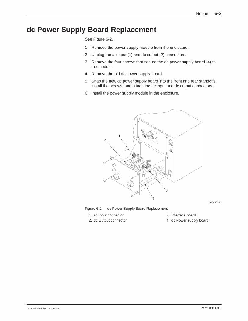
dc Power Supply Board ReplacementSee Figure 6-2.
1. Remove the power supply module from the enclosure.
2. Unplug the ac input (1) and dc output (2) connectors.
3. Remove the four screws that secure the dc power supply board (4) tothe module.
4. Remove the old dc power supply board.
5. Snap the new dc power supply board into the front and rear standoffs,install the screws, and attach the ac input and dc output connectors.
6. Install the power supply module in the enclosure.
1400566A
1
2
3
4
Figure 6-2 dc Power Supply Board Replacement
1. ac Input connector2. dc Output connector
3. Interface board4. dc Power supply board
Repair6-4
Part 303818E � 2002 Nordson Corporation
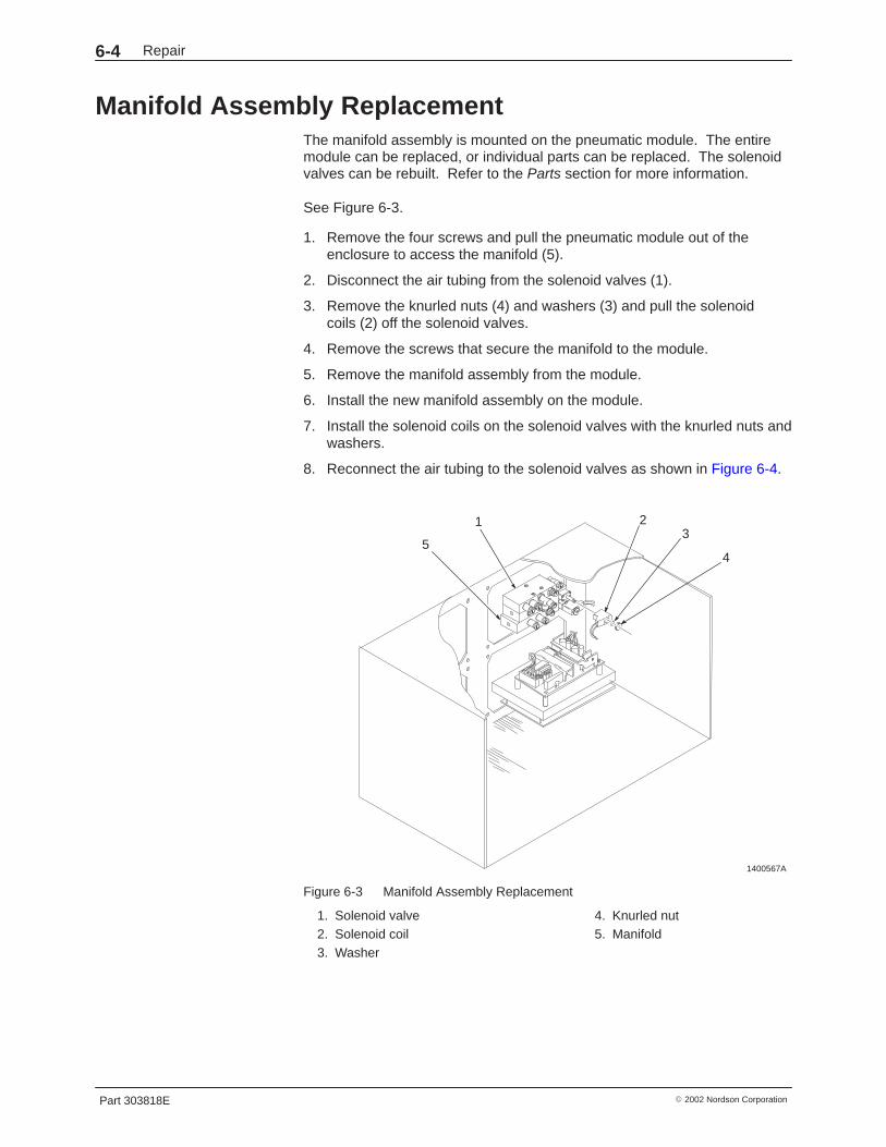
Manifold Assembly ReplacementThe manifold assembly is mounted on the pneumatic module. The entiremodule can be replaced, or individual parts can be replaced. The solenoidvalves can be rebuilt. Refer to the Parts section for more information.
See Figure 6-3.
1. Remove the four screws and pull the pneumatic module out of theenclosure to access the manifold (5).
2. Disconnect the air tubing from the solenoid valves (1).
3. Remove the knurled nuts (4) and washers (3) and pull the solenoidcoils (2) off the solenoid valves.
4. Remove the screws that secure the manifold to the module.
5. Remove the manifold assembly from the module.
6. Install the new manifold assembly on the module.
7. Install the solenoid coils on the solenoid valves with the knurled nuts andwashers.
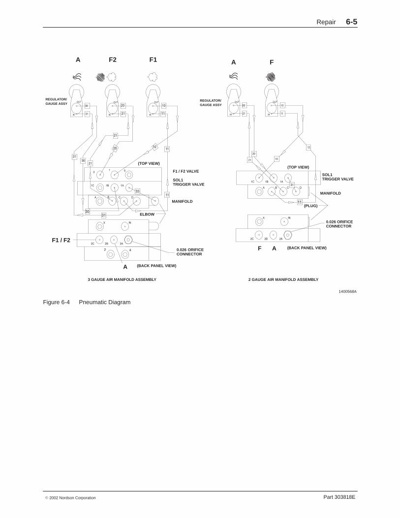
8. Reconnect the air tubing to the solenoid valves as shown in Figure 6-4.
1400567A
1 23
45
Figure 6-3 Manifold Assembly Replacement
1. Solenoid valve2. Solenoid coil3. Washer
4. Knurled nut5. Manifold
Repair 6-5
Part 303818E� 2002 Nordson Corporation
1400568A
F1 / F2 VALVE
SOL1TRIGGER VALVE
MANIFOLD
(TOP VIEW)
0.026 ORIFICECONNECTOR
(BACK PANEL VIEW)
3 GAUGE AIR MANIFOLD ASSEMBLY
ELBOW
A
F1 / F2
REGULATOR/GAUGE ASSY
REGULATOR/GAUGE ASSY
A F2 F1 A F
(TOP VIEW)
SOL1TRIGGER VALVE
MANIFOLD
0.026 ORIFICECONNECTOR
(PLUG)
(BACK PANEL VIEW)AF
2 GAUGE AIR MANIFOLD ASSEMBLY
Figure 6-4 Pneumatic Diagram

Repair6-6
Part 303818E � 2002 Nordson Corporation
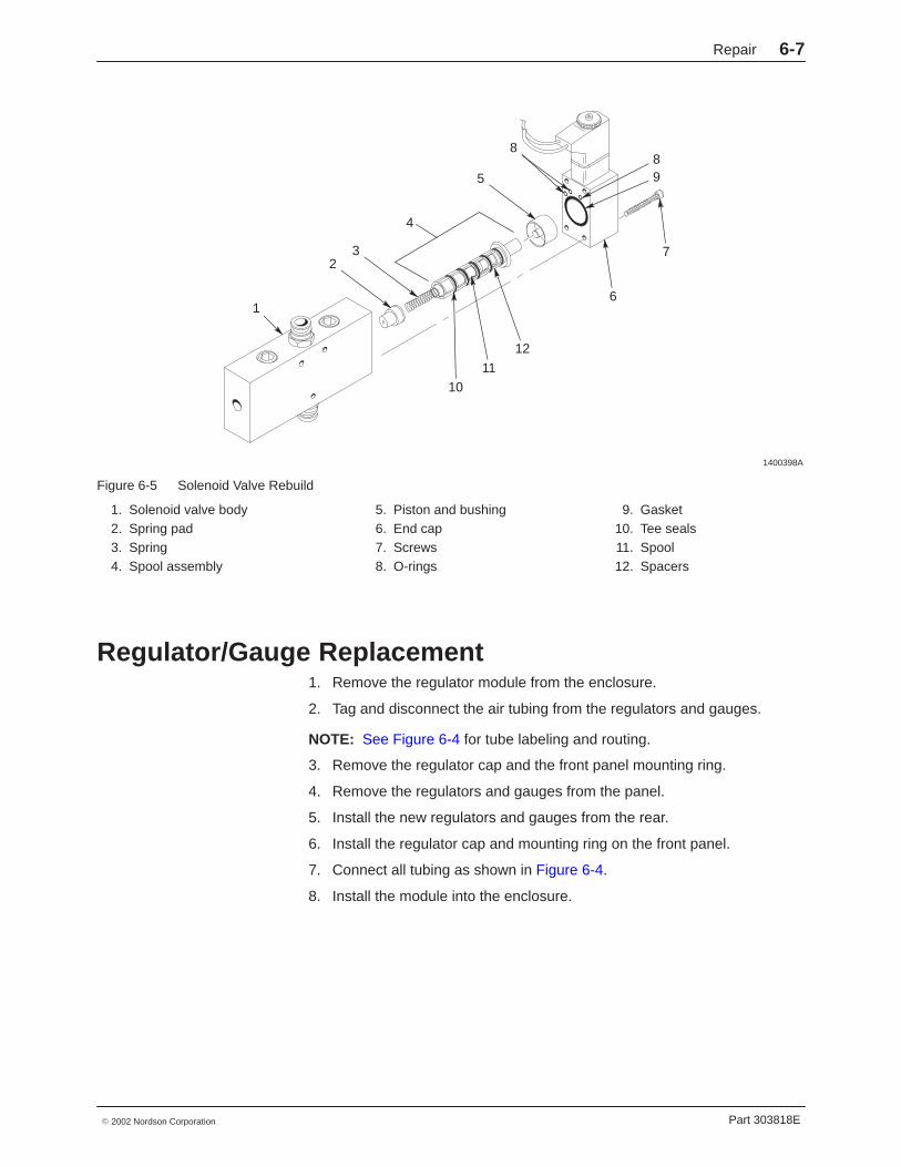
Solenoid Valve RebuildSee Figure 6-5. This procedure uses the valve seal, trigger valve, or F1/F2valve service kits to rebuild the solenoid valves. Refer to the Parts sectionfor more information.
NOTE: Seven tee seals are included in the seal kit. If you rebuild thetrigger valve, use all seven tee seals. If you rebuild the F1/F2 valve, you willonly use six tee seals.
1. Remove the manifold. Refer to Manifold Assembly Replacement forinstructions.
2. Remove the screws (7) and pull the end cap (6) off the solenoid valvebody (1). Make sure the three small O-rings (8) and flat roundgasket (9) remain in the end cap.
3. Remove the piston and bushing (5) from the valve body.
4. Push on the spring pad (2) to force the spool assembly (4) out of thevalve body.
5. Disassemble the spool assembly and clean and replace parts asnecessary.
6. Assemble the solenoid valve. Lightly lubricate the following items withthe lubricant included in the service kit before installing it them:
� piston (5) O-ring
� O-rings (8)
� gasket (9)
� tee seals (10)
� spool (11)
NOTE: The spacers (12) and tee seals (10) are identical and may beinstalled in any location along the spool (11). Use only six of the seventee seals provided in the seal kit when rebuilding the F1/F2 valve.
7. Install the spool assembly into the valve body.
8. Install the piston and bushing into the valve body.
9. Make sure that the small O-rings are aligned with the holes in the valvebody, and install the endcap using the four screws. Torque the screwsto 1 N•m (9 in.-lb).
Repair 6-7
Part 303818E� 2002 Nordson Corporation
1400398A
1
2
5
3
6
7
4
889
12
1110
Figure 6-5 Solenoid Valve Rebuild
1. Solenoid valve body2. Spring pad3. Spring4. Spool assembly
5. Piston and bushing6. End cap7. Screws8. O-rings
9. Gasket10. Tee seals11. Spool12. Spacers
Regulator/Gauge Replacement1. Remove the regulator module from the enclosure.
2. Tag and disconnect the air tubing from the regulators and gauges.
NOTE: See Figure 6-4 for tube labeling and routing.
3. Remove the regulator cap and the front panel mounting ring.
4. Remove the regulators and gauges from the panel.
5. Install the new regulators and gauges from the rear.
6. Install the regulator cap and mounting ring on the front panel.
7. Connect all tubing as shown in Figure 6-4.
8. Install the module into the enclosure.
Repair6-8
Part 303818E � 2002 Nordson Corporation
Parts 7-1
Part 303818E� 2002 Nordson Corporation
Section 7Parts
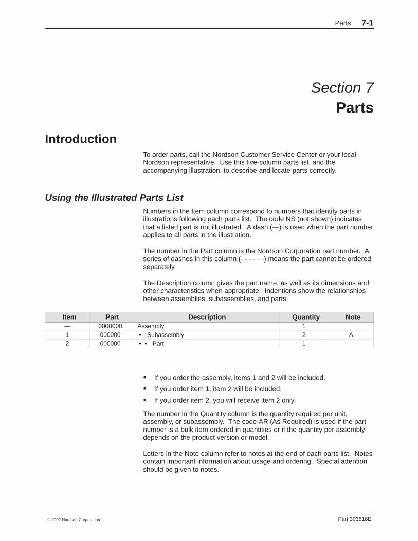
Introduction To order parts, call the Nordson Customer Service Center or your localNordson representative. Use this five-column parts list, and theaccompanying illustration, to describe and locate parts correctly.
Using the Illustrated Parts List Numbers in the Item column correspond to numbers that identify parts inillustrations following each parts list. The code NS (not shown) indicatesthat a listed part is not illustrated. A dash (—) is used when the part numberapplies to all parts in the illustration.
The number in the Part column is the Nordson Corporation part number. Aseries of dashes in this column (- - - - - -) means the part cannot be orderedseparately.
The Description column gives the part name, as well as its dimensions andother characteristics when appropriate. Indentions show the relationshipsbetween assemblies, subassemblies, and parts.
Item Part Description Quantity Note— 0000000 Assembly 11 000000 � Subassembly 2 A2 000000 � � Part 1
� If you order the assembly, items 1 and 2 will be included.
� If you order item 1, item 2 will be included.
� If you order item 2, you will receive item 2 only.
The number in the Quantity column is the quantity required per unit,assembly, or subassembly. The code AR (As Required) is used if the partnumber is a bulk item ordered in quantities or if the quantity per assemblydepends on the product version or model.
Letters in the Note column refer to notes at the end of each parts list. Notescontain important information about usage and ordering. Special attentionshould be given to notes.
Parts7-2
Part 303818E � 2002 Nordson Corporation
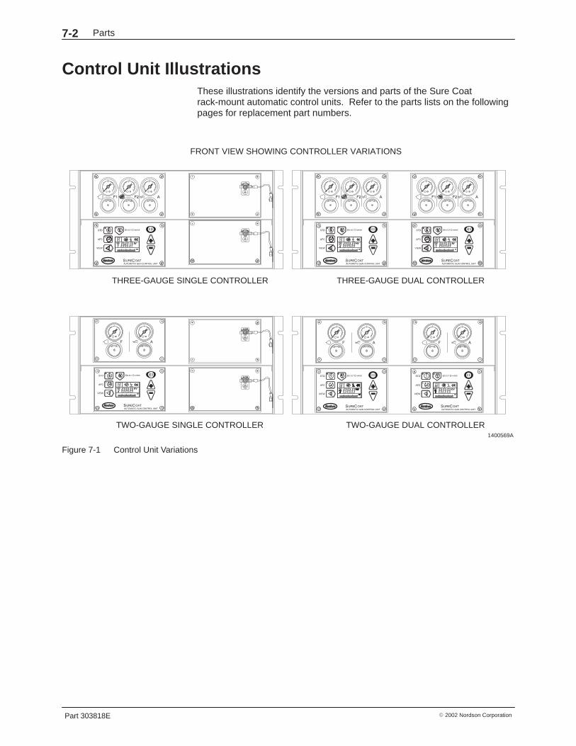
Control Unit IllustrationsThese illustrations identify the versions and parts of the Sure Coatrack-mount automatic control units. Refer to the parts lists on the followingpages for replacement part numbers.
1400569A
THREE-GAUGE SINGLE CONTROLLER
TWO-GAUGE DUAL CONTROLLERTWO-GAUGE SINGLE CONTROLLER
FRONT VIEW SHOWING CONTROLLER VARIATIONS
THREE-GAUGE DUAL CONTROLLER
Figure 7-1 Control Unit Variations
Parts 7-3
Part 303818E� 2002 Nordson Corporation
1400570A
5
4
4
5
1
12
14 13
12
BACK VIEW
FRONT VIEWBLANK PANEL CONSTRUCTION
BLANK PANEL CONSTRUCTION
DETAIL A DETAIL B DETAIL C
SEE DETAIL C
SEE DETAIL B
SEE DETAIL B
4 PLACES FOR DOUBLE UNIT6 PLACES FOR SINGLE UNIT
GROUND STUD DETAILSSHOWN ENLARGED
BACK VIEWSHOWN ROTATED
SEE DETAIL C
TOP VIEW
FRONT VIEW SIDE VIEW
2 2
1
4
512
14
9
THREE-GAUGE
3 3
910 11
15
15
1617
1418
678
678
678
2020
20 20
20
DUAL CONTROLLER SHOWN
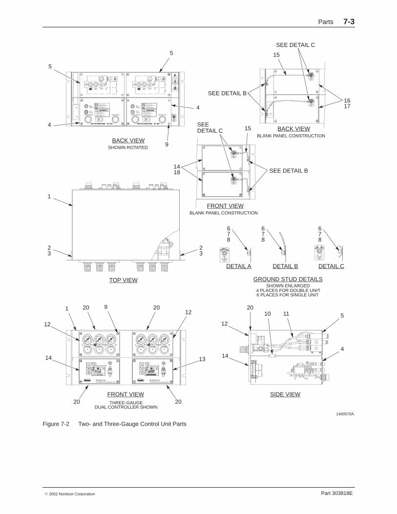
Figure 7-2 Two- and Three-Gauge Control Unit Parts
Parts7-4
Part 303818E � 2002 Nordson Corporation
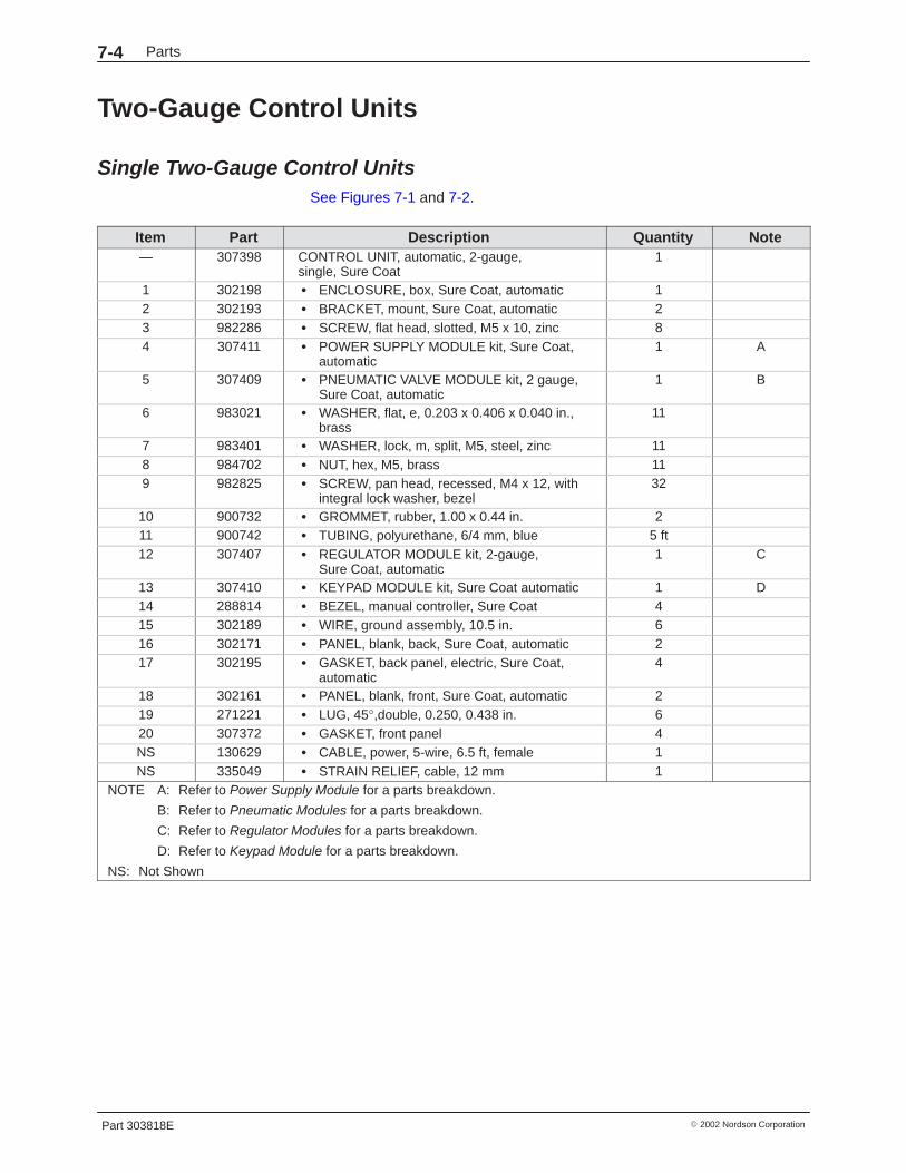
Two-Gauge Control Units
Single Two-Gauge Control UnitsSee Figures 7-1 and 7-2.
Item Part Description Quantity Note— 307398 CONTROL UNIT, automatic, 2-gauge,
single, Sure Coat1
1 302198 � ENCLOSURE, box, Sure Coat, automatic 12 302193 � BRACKET, mount, Sure Coat, automatic 23 982286 � SCREW, flat head, slotted, M5 x 10, zinc 84 307411 � POWER SUPPLY MODULE kit, Sure Coat,
automatic1 A
5 307409 � PNEUMATIC VALVE MODULE kit, 2 gauge,Sure Coat, automatic
1 B
6 983021 � WASHER, flat, e, 0.203 x 0.406 x 0.040 in.,brass
11
7 983401 � WASHER, lock, m, split, M5, steel, zinc 118 984702 � NUT, hex, M5, brass 119 982825 � SCREW, pan head, recessed, M4 x 12, with
integral lock washer, bezel32
10 900732 � GROMMET, rubber, 1.00 x 0.44 in. 211 900742 � TUBING, polyurethane, 6/4 mm, blue 5 ft12 307407 � REGULATOR MODULE kit, 2-gauge,
Sure Coat, automatic1 C
13 307410 � KEYPAD MODULE kit, Sure Coat automatic 1 D14 288814 � BEZEL, manual controller, Sure Coat 415 302189 � WIRE, ground assembly, 10.5 in. 616 302171 � PANEL, blank, back, Sure Coat, automatic 217 302195 � GASKET, back panel, electric, Sure Coat,
automatic4
18 302161 � PANEL, blank, front, Sure Coat, automatic 219 271221 � LUG, 45°,double, 0.250, 0.438 in. 620 307372 � GASKET, front panel 4NS 130629 � CABLE, power, 5-wire, 6.5 ft, female 1NS 335049 � STRAIN RELIEF, cable, 12 mm 1
NOTE A: Refer to Power Supply Module for a parts breakdown.
B: Refer to Pneumatic Modules for a parts breakdown.
C: Refer to Regulator Modules for a parts breakdown.
D: Refer to Keypad Module for a parts breakdown.
NS: Not Shown

Parts 7-5
Part 303818E� 2002 Nordson Corporation
Dual Two-Gauge Control UnitsSee Figures 7-1 and 7-2.
Item Part Description Quantity Note— 307397 CONTROL UNIT, automatic, 2-gauge,
double, Sure Coat1
1 302198 � ENCLOSURE, box, Sure Coat, automatic 12 302193 � BRACKET, mount, Sure Coat, automatic 23 982286 � SCREW, flat head, slotted, M5 x 10, zinc 84 307411 � POWER SUPPLY MODULE kit, Sure Coat,
automatic2 A
5 307409 � PNEUMATIC VALVE MODULE kit, 2 gauge,Sure Coat, automatic
2 B
6 983021 � WASHER, flat, e, 0.203 x 0.406 x 0.040 in.,brass
7
7 983401 � WASHER, lock, m, split, M5, steel, zinc 78 984702 � NUT, hex, M5, brass 79 982825 � SCREW, pan head, recessed, M4 x 12, with
integral lock washer, bezel32
10 900732 � GROMMET, rubber, 1.00 x 0.44 in. 211 900742 � TUBING, polyurethane, 6/4 mm, blue 9.5 ft12 307407 � REGULATOR MODULE kit, 2-gauge,
Sure Coat, automatic2 C
13 307410 � KEYPAD MODULE kit, Sure Coat automatic 2 D14 288814 � BEZEL, manual controller, Sure Coat 415 302189 � WIRE, ground assembly, 10.5 in. 419 271221 � LUG, 45°, double, 0.250, 0.438 in. 420 307372 � GASKET, front panel 4NS 130629 � CABLE, power, 5-wire, 6.5 ft, female 2NS 335049 � STRAIN RELIEF, cable, 12 mm 2
NOTE A: Refer to Power Supply Module for a parts breakdown.
B: Refer to Pneumatic Modules for a parts breakdown.
C: Refer to Regulator Modules for a parts breakdown.
D: Refer to Keypad Module for a parts breakdown.
NS: Not Shown

Parts7-6
Part 303818E � 2002 Nordson Corporation
Three-Gauge Control Units
Single Three-Gauge Control UnitsSee Figures 7-1 and 7-2.
Item Part Description Quantity Note— 307396 CONTROL UNIT, automatic, 3-gauge,
single, Sure Coat1
1 302198 � ENCLOSURE, box, Sure Coat, automatic 12 302193 � BRACKET, mount, Sure Coat, automatic 23 982286 � SCREW, flat head, slotted, M5 x 10, zinc 84 307411 � POWER SUPPLY MODULE kit, Sure Coat,
automatic1 A
5 307408 � PNEUMATIC VALVE MODULE kit, 3-gauge,Sure Coat, automatic
1 B
6 983021 � WASHER, flat, e, 0.203 x 0.406 x 0.040 in.,brass
11
7 983401 � WASHER, lock, m, split, M5, steel, zinc 118 984702 � NUT, hex, M5, brass 119 982825 � SCREW, pan head, recessed, M4 x 12, with
integral lock washer, bezel32
10 900732 � GROMMET, rubber, 1.00 x 0.44 in. 211 900742 � TUBING, polyurethane, 6/4 mm, blue 7 ft12 307406 � REGULATOR MODULE kit, 3-gauge,
Sure Coat, automatic1 C
13 307410 � KEYPAD MODULE kit, Sure Coat, automatic 1 D14 288814 � BEZEL, manual controller, Sure Coat 415 302189 � WIRE, ground assembly, 10.5 in. 616 302171 � PANEL, blank, back, Sure Coat, automatic 217 302195 � GASKET, back panel, electric, Sure Coat,
automatic4
18 302161 � PANEL, blank, front, Sure Coat, automatic 219 271221 � LUG, 45°, double, 0.250, 0.438 in. 620 307372 � GASKET, front panel 4NS 130629 � CABLE, power, 5-wire, 6.5 ft, female 1NS 335049 � STRAIN RELIEF, cable, 12 mm 1
NOTE A: Refer to Power Supply Module for a parts breakdown.
B: Refer to Pneumatic Modules for a parts breakdown.
C: Refer to Regulator Modules for a parts breakdown.
D: Refer to Keypad Module for a parts breakdown.
NS: Not Shown

Parts 7-7
Part 303818E� 2002 Nordson Corporation
Dual Three-Gauge Control UnitsSee Figures 7-1 and 7-2.
Item Part Description Quantity Note— 307395 CONTROL UNIT, automatic, 3-gauge, double,
Sure Coat1
1 302198 � ENCLOSURE, box, Sure Coat, automatic 12 302193 � BRACKET, mount, Sure Coat, automatic 23 982286 � SCREW, flat head, slotted, M5 x 10, zinc 84 307411 � POWER SUPPLY MODULE kit, Sure Coat,
automatic2 A
5 307408 � PNEUMATIC VALVE MODULE kit, 3-gauge,Sure Coat, automatic
2 B
6 983021 � WASHER, flat, e, 0.203 x 0.406 x 0.040 in.,brass
7
7 983401 � WASHER, lock, m, split, M5, steel, zinc 78 984702 � NUT, hex, M5, brass 79 982825 � SCREW, pan head, recessed, M4 x 12, with
integral lock washer, bezel32
10 900732 � GROMMET, rubber, 1.00 x 0.44 in. 211 900742 � TUBING, polyurethane, 6/4 mm, blue 13.5 ft12 307406 � REGULATOR MODULE kit, 3-gauge,
Sure Coat, automatic2 C
13 307410 � KEYPAD MODULE kit, Sure Coat, automatic 2 D14 288814 � BEZEL, manual controller, Sure Coat 415 302189 � WIRE, ground assembly, 10.5 in. 419 271221 � LUG, 45°, double, 0.250, 0.438 in. 420 307372 � GASKET, front panel 4NS 130629 � CABLE, power, 5-wire, 6.5 ft, female 2NS 335049 � STRAIN RELIEF, cable, 12 mm 2
NOTE A: Refer to Power Supply Module for a parts breakdown.
B: Refer to Pneumatic Modules for a parts breakdown.
C: Refer to Regulator Modules for a parts breakdown.
D: Refer to Keypad Module for a parts breakdown.
NS: Not Shown
Parts7-8
Part 303818E � 2002 Nordson Corporation
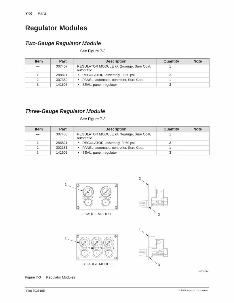
Regulator Modules
Two-Gauge Regulator ModuleSee Figure 7-3.
Item Part Description Quantity Note— 307407 REGULATOR MODULE kit, 2-gauge, Sure Coat,
automatic1
1 288821 � REGULATOR, assembly, 0–60 psi 22 307389 � PANEL, automatic, controller, Sure Coat 13 141603 � SEAL, panel, regulator 2
Three-Gauge Regulator ModuleSee Figure 7-3.
Item Part Description Quantity Note— 307406 REGULATOR MODULE kit, 3-gauge, Sure Coat,
automatic1
1 288821 � REGULATOR, assembly, 0–60 psi 32 302181 � PANEL, automatic, controller, Sure Coat 13 141603 � SEAL, panel, regulator 3
1400571A
0 0 0
0 0
2 GAUGE MODULE
3 GAUGE MODULE
1
1
2
2
3
3
Figure 7-3 Regulator Modules
Parts 7-9
Part 303818E� 2002 Nordson Corporation
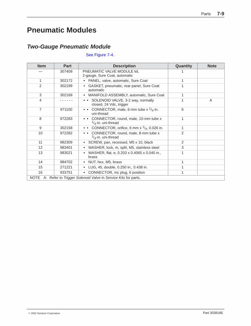
Pneumatic Modules
Two-Gauge Pneumatic ModuleSee Figure 7-4.
Item Part Description Quantity Note— 307409 PNEUMATIC VALVE MODULE kit,
2-gauge, Sure Coat, automatic1
1 302172 � PANEL, valve, automatic, Sure Coat 12 302199 � GASKET, pneumatic, rear panel, Sure Coat
automatic1
3 302169 � MANIFOLD ASSEMBLY, automatic, Sure Coat 14 - - - - - - � � SOLENOID VALVE, 3-2 way, normally
closed, 24 Vdc, trigger1 A
7 971100 � � CONNECTOR, male, 6-mm tube x 1/4-in.uni-thread
6
8 972283 � � CONNECTOR, round, male, 10-mm tube x1/4-in. uni-thread
1
9 302158 � � CONNECTOR, orifice, 6 mm x 1/4, 0.026 in. 110 972282 � � CONNECTOR, round, male, 8-mm tube x
1/4-in. uni-thread2
11 982309 � SCREW, pan, recessed, M5 x 10, black 212 983401 � WASHER, lock, m, split, M5, stainless steel 313 983021 � WASHER, flat, e, 0.203 x 0.4065 x 0.040 in.,
brass1
14 984702 � NUT, hex, M5, brass 115 271221 � LUG, 45, double, 0.250 in., 0.438 in. 116 933751 � CONNECTOR, mc plug, 6 position 1
NOTE A: Refer to Trigger Solenoid Valve in Service Kits for parts.
Parts7-10
Part 303818E � 2002 Nordson Corporation
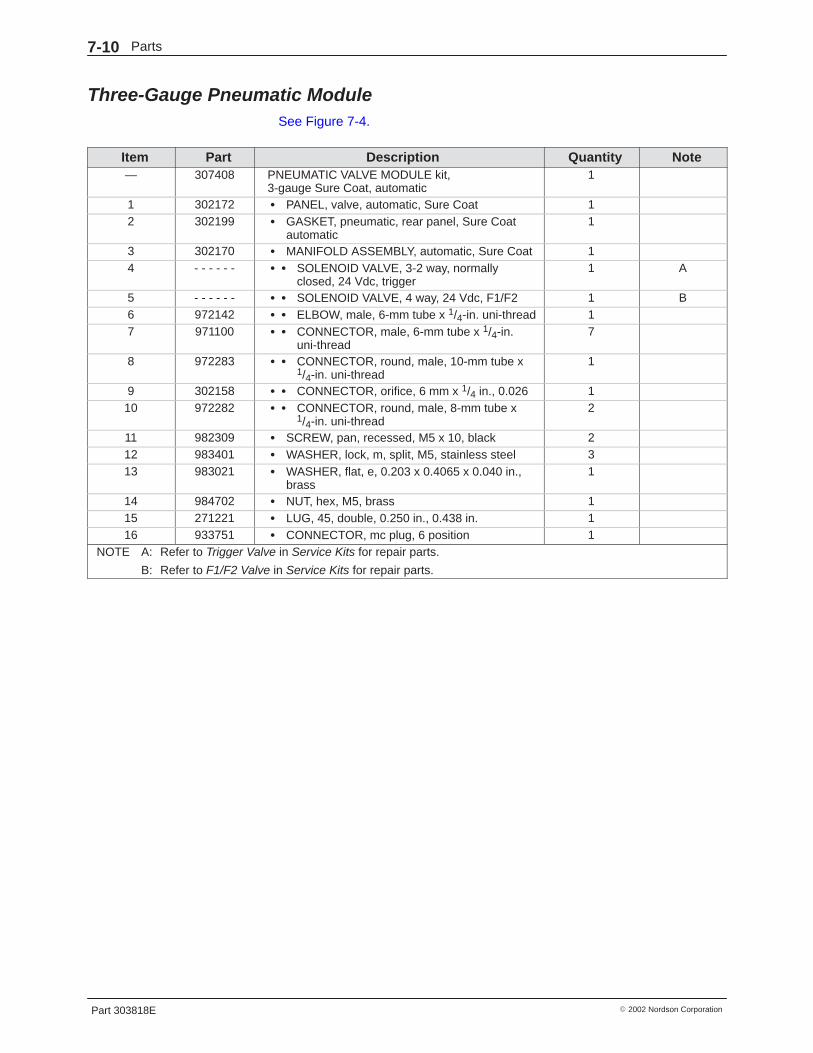
Three-Gauge Pneumatic ModuleSee Figure 7-4.
Item Part Description Quantity Note— 307408 PNEUMATIC VALVE MODULE kit,
3-gauge Sure Coat, automatic1
1 302172 � PANEL, valve, automatic, Sure Coat 12 302199 � GASKET, pneumatic, rear panel, Sure Coat
automatic1
3 302170 � MANIFOLD ASSEMBLY, automatic, Sure Coat 14 - - - - - - � � SOLENOID VALVE, 3-2 way, normally
closed, 24 Vdc, trigger1 A
5 - - - - - - � � SOLENOID VALVE, 4 way, 24 Vdc, F1/F2 1 B6 972142 � � ELBOW, male, 6-mm tube x 1/4-in. uni-thread 17 971100 � � CONNECTOR, male, 6-mm tube x 1/4-in.
uni-thread7
8 972283 � � CONNECTOR, round, male, 10-mm tube x1/4-in. uni-thread
1
9 302158 � � CONNECTOR, orifice, 6 mm x 1/4 in., 0.026 110 972282 � � CONNECTOR, round, male, 8-mm tube x
1/4-in. uni-thread2
11 982309 � SCREW, pan, recessed, M5 x 10, black 212 983401 � WASHER, lock, m, split, M5, stainless steel 313 983021 � WASHER, flat, e, 0.203 x 0.4065 x 0.040 in.,
brass1
14 984702 � NUT, hex, M5, brass 115 271221 � LUG, 45, double, 0.250 in., 0.438 in. 116 933751 � CONNECTOR, mc plug, 6 position 1
NOTE A: Refer to Trigger Valve in Service Kits for repair parts.
B: Refer to F1/F2 Valve in Service Kits for repair parts.

Parts 7-11
Part 303818E� 2002 Nordson Corporation
1400572A
2 GAUGE MANIFOLD
IN
OUT
3 GAUGE MANIFOLD
PNEUMATIC BACK PANEL
GROUND STUD DETAIL
IN
OUT
7
7
16
3
11
12
1
9
16
7
3
1
88
9
6
7
7
1010
2 2
12
131415
4 4 5
1 1 2
Figure 7-4 Pneumatic Modules
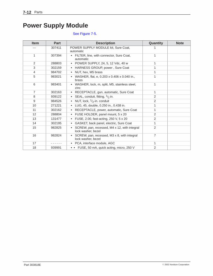
Parts7-12
Part 303818E � 2002 Nordson Corporation
Power Supply Module See Figure 7-5.
Item Part Description Quantity Note— 307411 POWER SUPPLY MODULE kit, Sure Coat,
automatic1
1 307394 � FILTER, line, with connector, Sure Coat,automatic
1
2 288803 � POWER SUPPLY, 24, 5, 12 Vdc, 40 w 13 302159 � HARNESS GROUP, power , Sure Coat 14 984702 � NUT, hex, M5 brass 15 983021 � WASHER, flat, e, 0.203 x 0.406 x 0.040 in.,
brass1
6 983401 � WASHER, lock, m, split, M5, stainless steel,zinc
1
7 302163 � RECEPTACLE, gun, automatic, Sure Coat 18 939122 � SEAL, conduit, fitting, 1/2 in. 29 984526 � NUT, lock, 1/2-in. conduit 210 271221 � LUG, 45, double, 0.250 in., 0.438 in. 111 302162 � RECEPTACLE, power, automatic, Sure Coat 112 288804 � FUSE HOLDER, panel mount, 5 x 20 213 131477 � FUSE, 2.00, fast-acting, 250 V, 5 x 20 214 302195 � GASKET, back panel, electric, Sure Coat 115 982825 � SCREW, pan, recessed, M4 x 12, with integral
lock washer, bezel2
16 982824 � SCREW, pan, recessed, M3 x 8, with integrallock washer, bezel
7
17 - - - - - - � PCA, interface module, AGC 118 939991 � � FUSE, 50 mA, quick acting, micro, 250 V 2
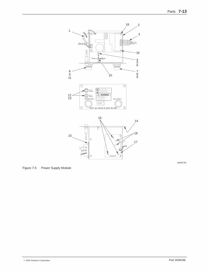
Parts 7-13
Part 303818E� 2002 Nordson Corporation
1400573A
1
8911
789
3
2
15
4
10
56
16
17
1213
16
18
16
14
Figure 7-5 Power Supply Module
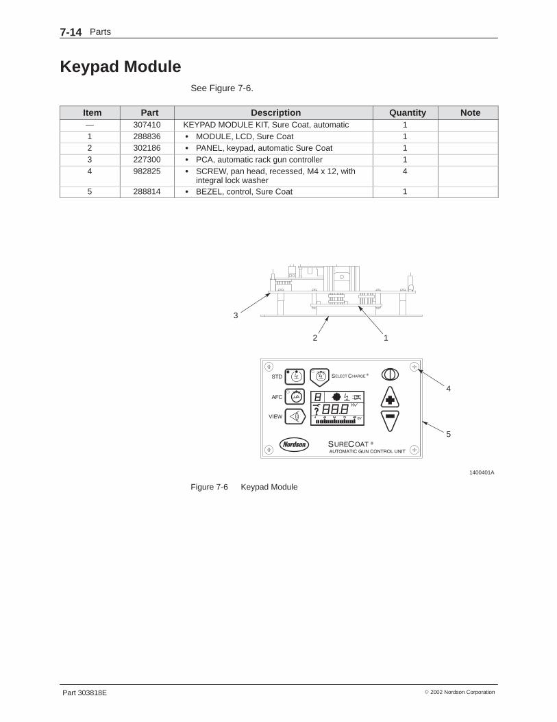
Parts7-14
Part 303818E � 2002 Nordson Corporation
Keypad ModuleSee Figure 7-6.
Item Part Description Quantity Note— 307410 KEYPAD MODULE KIT, Sure Coat, automatic 11 288836 � MODULE, LCD, Sure Coat 12 302186 � PANEL, keypad, automatic Sure Coat 13 227300 � PCA, automatic rack gun controller 14 982825 � SCREW, pan head, recessed, M4 x 12, with
integral lock washer4
5 288814 � BEZEL, control, Sure Coat 1
1400401A
1
4
5
2
3
Figure 7-6 Keypad Module

Parts 7-15
Part 303818E� 2002 Nordson Corporation
Solenoid Valve KitsUse these lists to order service kits for the trigger and auxiliary solenoidvalves.
Trigger ValveSee Figure 7-7.
Item Part Description Quantity Note— 333677 SERVICE KIT, trigger valve 1 A1 - - - - - - � SPRING 12 1027108 � SEAL KIT, spool, valve 1
NS - - - - - - � � SEAL, tee 7NS - - - - - - � � LUBRICANT 13 - - - - - - � SPOOL, molded 3/2/2 14 - - - - - - � O-RING, piston 1
NOTE A: See Figure 7-4, item 4 for the location of the trigger valve.
NS: Not Shown
1400574A
3a
1
4
3
2
2
Figure 7-7 Solenoid Valve Kits

Parts7-16
Part 303818E � 2002 Nordson Corporation
F1/F2 ValveSee Figure 7-7.
Item Part Description Quantity Note— 333678 SERVICE KIT, F1/F2 valve 1 A1 - - - - - - � SPRING 12 1027108 � SEAL KIT, spool, valve 1 B
NS - - - - - - � � SEAL, tee 7 BNS - - - - - - � � LUBRICANT 13a - - - - - - � SPOOL, molded 5/2 14 - - - - - - � O-RING, piston 1
NOTE A: See Figure 7-4, item 5 for the location of the F1/F2 valve.
B: The valve seal service kit, part 1027108, includes seven tee seals. Only six tee seals are needed torebuild the auxiliary F1/F2 valve. Discard the spare tee seal.
NS: Not Shown
Jumper HarnessSee Figure 7-8.
Part Description Note332776 HARNESS, jumper
1400575A
Figure 7-8 Jumper Harness
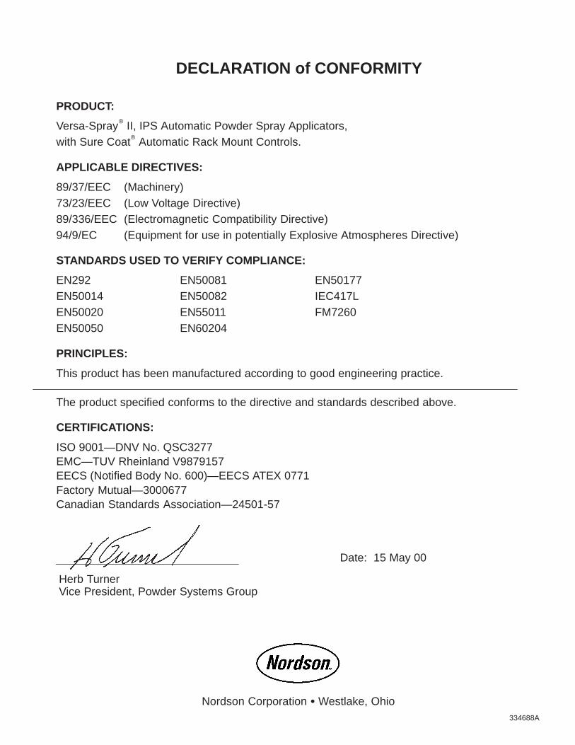
334688A
DECLARATION of CONFORMITY
PRODUCT:
Versa-Spray� II, IPS Automatic Powder Spray Applicators,with Sure Coat� Automatic Rack Mount Controls.
APPLICABLE DIRECTIVES:
89/37/EEC (Machinery)73/23/EEC (Low Voltage Directive)89/336/EEC (Electromagnetic Compatibility Directive)94/9/EC (Equipment for use in potentially Explosive Atmospheres Directive)
STANDARDS USED TO VERIFY COMPLIANCE:
EN292 EN50081 EN50177EN50014 EN50082 IEC417LEN50020 EN55011 FM7260EN50050 EN60204
PRINCIPLES:
This product has been manufactured according to good engineering practice.
The product specified conforms to the directive and standards described above.
CERTIFICATIONS:
ISO 9001—DNV No. QSC3277EMC—TUV Rheinland V9879157EECS (Notified Body No. 600)—EECS ATEX 0771Factory Mutual—3000677Canadian Standards Association—24501-57
Date: 15 May 00
Herb TurnerVice President, Powder Systems Group
Nordson Corporation � Westlake, Ohio