SUPPRESSION OF FLUID FORCES ACTING ON TWO SQUARE PRISMS IN A TANDEM ARRANGEMENT BY PASSIVE CONTROL...
20
Journal of Fluids and Structures (2002) 16(8), 1073–1092 doi:10.1006/jfls.2002.0458 available online at http://www.idealibrary.com on SUPPRESSION OF FLUID FORCES ACTING ON TWO SQUARE PRISMS IN A TANDEM ARRANGEMENT BY PASSIVE CONTROL OF FLOW MD. Mahbub Alam, M. Moriya, K. Takai and H. Sakamoto Department of Mechanical Engineering, Kitami Institute of Technology Kitami 090-8507, Japan (Received 10 April 2000; and in final form 9 October 2001) The suppression of fluid forces acting on two square prisms in a tandem arrangement in which a flow approaching the upstream prism was controlled by a thin flat plate was examined, with variation in spacing between the plate and the upstream prism. The width of the plate was one- ninth of the prism width. The position of the control plate was varied from the front surface of the upstream prism to 225 times the prism width in the upstream direction, and the position of the downstream prism was varied from the rear surface of the upstream prism to 10 times the prism width in the downstream direction. A dramatic decrease in fluid forces acting on both prisms was observed for a certain range of control plate positions. For such optimum positions of the control plate, the shear layers that separated from the control plate attached near the edges of the front surface of the upstream prism and each shear layer bifurcated into two layers, one part of the shear layers making a quasi-steady recirculating region between the control plate and the upstream prism, and the other part separating from the leading edges and attaching again to the side-surfaces of the upstream prism. When the control plate was placed with spacings S=W ¼ 1 50 1 90 (S: spacing between the control plate and the upstream prism, W: width of the prism), the above-mentioned flow pattern appeared, and the fluid forces and vortex shedding of the upstream prism were almost completely suppressed. Also, the upstream prism was found to be insensitive to the existence of the downstream prism when the latter was located downstream, approximately six or more times the prism width. # 2002 Elsevier Science Ltd. All rights reserved. 1. INTRODUCTION Manyattempts have been made to suppress fluid forces acting on circular-, rectangular-, and square-sectioned models, and many methods for suppressing fluid forces acting on such models have been developed. Bearman (1965) attempted to reduce fluid forces as well as vortex shedding by fitting a splitter plate to the rear of a rectangular prism. Strykowski & Sreenivasan (1990) and Sakamoto et al. (1991) successfully suppressed vortex shedding by setting a control cylinder in a separated shear layer on one side of a circular cylinder and a square prism, respectively. Lesage & Gartshore (1987) and Igarashi & Itoh (1993) reduced time-averaged drag force by setting a small rod upstream of a square prism and, most recently, Sakamoto et al. (1997) evaluated the fluid forces acting on a square prism by changing the width of a flat plate and its position on the center-line. They found that the optimum width of the plate for suppression of fluid forces is approximately 1/10 of that of the prism. 0889-9746/02/081073 + 20 $35.00/0 # 2002 Elsevier Science Ltd. All rights reserved.
-
Upload
md-mahbub-alam -
Category
Documents
-
view
213 -
download
1
Transcript of SUPPRESSION OF FLUID FORCES ACTING ON TWO SQUARE PRISMS IN A TANDEM ARRANGEMENT BY PASSIVE CONTROL...

Journal of Fluids and Structures (2002) 16(8), 1073–1092doi:10.1006/jfls.2002.0458 available online at http://www.idealibrary.com on
SUPPRESSION OF FLUID FORCES ACTING ON TWOSQUARE PRISMS IN A TANDEM ARRANGEMENT BY
PASSIVE CONTROL OF FLOW
MD. Mahbub Alam, M. Moriya, K. Takai and H. Sakamoto
Department of Mechanical Engineering, Kitami Institute of TechnologyKitami 090-8507, Japan
(Received 10 April 2000; and in final form 9 October 2001)
The suppression of fluid forces acting on two square prisms in a tandem arrangement in whicha flow approaching the upstream prism was controlled by a thin flat plate was examined, withvariation in spacing between the plate and the upstream prism. The width of the plate was one-ninth of the prism width. The position of the control plate was varied from the front surface ofthe upstream prism to 2�25 times the prism width in the upstream direction, and the position ofthe downstream prism was varied from the rear surface of the upstream prism to 10 times theprism width in the downstream direction. A dramatic decrease in fluid forces acting on bothprisms was observed for a certain range of control plate positions. For such optimumpositions of the control plate, the shear layers that separated from the control plate attachednear the edges of the front surface of the upstream prism and each shear layer bifurcated intotwo layers, one part of the shear layers making a quasi-steady recirculating region between thecontrol plate and the upstream prism, and the other part separating from the leading edgesand attaching again to the side-surfaces of the upstream prism. When the control plate wasplaced with spacings S=W ¼ 1�50 � 1�90 (S: spacing between the control plate and theupstream prism, W : width of the prism), the above-mentioned flow pattern appeared, and thefluid forces and vortex shedding of the upstream prism were almost completely suppressed.Also, the upstream prism was found to be insensitive to the existence of the downstream prismwhen the latter was located downstream, approximately six or more times the prism width.
# 2002 Elsevier Science Ltd. All rights reserved.
1. INTRODUCTION
Manyattempts have been made to suppress fluid forces acting on circular-, rectangular-,and square-sectioned models, and many methods for suppressing fluid forces acting onsuch models have been developed. Bearman (1965) attempted to reduce fluid forces as wellas vortex shedding by fitting a splitter plate to the rear of a rectangular prism. Strykowski& Sreenivasan (1990) and Sakamoto et al. (1991) successfully suppressed vortex sheddingby setting a control cylinder in a separated shear layer on one side of a circular cylinderand a square prism, respectively. Lesage & Gartshore (1987) and Igarashi & Itoh (1993)reduced time-averaged drag force by setting a small rod upstream of a square prism and,most recently, Sakamoto et al. (1997) evaluated the fluid forces acting on a square prismby changing the width of a flat plate and its position on the center-line. They found thatthe optimum width of the plate for suppression of fluid forces is approximately 1/10 ofthat of the prism.
0889-9746/02/081073+20 $35.00/0 # 2002 Elsevier Science Ltd. All rights reserved.

MD. MAHBUB ALAM, M. MORIYA, K. TAKAI AND H. SAKAMOTO1074
The notable features of the flow over two bodies in a tandem arrangement areintensification of aerodynamic forces and unexpected vibration of the bodies. The fluidforces acting on the bodies change dramatically with changes in the spacing between them.Such an arrangement of two bodies has many practical applications in various fields ofengineering, such as twin-conductor transmission lines, two parallel suspension bridges,radar mast vibrations, twin chimney stacks, heat exchanger tubes, and various structureson land and in the ocean.Zdravkovich (1977) investigated the interference between two equal circular cylinders in
a tandem arrangement, a side-by-side arrangement and a staggered arrangement, and hereported that there is a discontinuous change in the flow pattern and fluid forces acting onthe cylinders at some critical spacing, where two types of flow pattern produce two valuesof force and the two patterns intermittently switch. Moriya & Sakamoto (1986)experimentally studied the flow around two circular cylinders in a tandem arrangementat a Reynolds number of 6�54� 104, in which the upstream prism is forcibly vibratedtransversely with a vortex shedding frequency near that of the vortex shedding from thecylinder at rest. They concluded that the critical spacing between the cylinders for the flowto be switched from reattachment flow to jump flow is 2 times the cylinder diameter, andthat the critical spacing is 2�5 times the cylinder diameter when both cylinders are at rest.Wind tunnel experiments were conducted on two square prisms in a tandem arrangementby Sakamoto et al. (1987) to determine the characteristics of flow and the behavior oftime-averaged and fluctuating fluid forces. Thus, a number of previous studies have shownthat there exists a critical spacing, at which discontinuity of fluid forces occurs due tochange from one stable flow pattern to another, when two bodies are in a tandemarrangement. This change in the flow pattern creates large aerodynamic forces acting onthe bodies. However, there have been no studies on suppression of fluid forces acting ontwo bodies in a tandem arrangement or on the jump phenomenon, which intensifies thefluid forces.Hence, the aim of the present work was to find a way to suppress the fluid forces and the
discontinuity of fluid forces acting on two two-dimensional square prisms in a tandemarrangement, which is regarded as the most fundamental arrangement. In order to achievethis aim, the approaching flow on an upstream prism was controlled to change thebehavior of shear layers by placing a control plate centrally in front of the upstream prism.Time-averaged (steady) and fluctuating fluid forces acting on the two prisms wereexamined to determine the amount of reduction and to determine the optimum position ofthe control plate. In addition, the mechanism of flow control, structure of the controlledwake, and behavior of the controlled surrounding flow were investigated in detail on thebasis of surface pressure distributions, vortex shedding frequency and visualized surfaceoil-flow patterns.
2. EXPERIMENTAL ARRANGEMENT AND PROCEDURES
The experiments were performed in a low-speed, closed-circuit wind tunnel. The test-section of the tunnel was rectangular, with a height of 0�6m, width of 0�4m and length of5�4m. Two types of square prism were used for the experiments: one with a load cell insidefor the measurement of fluid forces, and the other with a semiconductor pressuretransducer inside for the measurement of time-averaged and fluctuating pressure. Bothprisms had a width of 42mm and length of 400mm, spanning the width of the test-sectionof the wind tunnel. As shown in Figure 1, the prism for the measurement of fluid forceswas composed of two parts: an active prism (‘‘live’’ section) and a dummy prism; a load
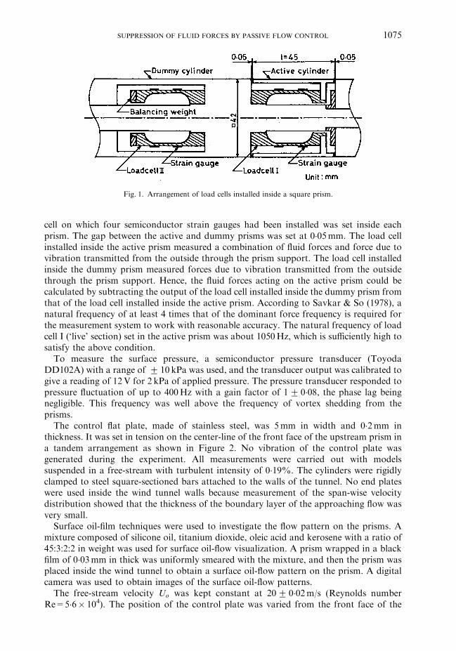
Fig. 1. Arrangement of load cells installed inside a square prism.
SUPPRESSION OF FLUID FORCES BY PASSIVE FLOW CONTROL 1075
cell on which four semiconductor strain gauges had been installed was set inside eachprism. The gap between the active and dummy prisms was set at 0�05mm. The load cellinstalled inside the active prism measured a combination of fluid forces and force due tovibration transmitted from the outside through the prism support. The load cell installedinside the dummy prism measured forces due to vibration transmitted from the outsidethrough the prism support. Hence, the fluid forces acting on the active prism could becalculated by subtracting the output of the load cell installed inside the dummy prism fromthat of the load cell installed inside the active prism. According to Savkar & So (1978), anatural frequency of at least 4 times that of the dominant force frequency is required forthe measurement system to work with reasonable accuracy. The natural frequency of loadcell I (‘live’ section) set in the active prism was about 1050Hz, which is sufficiently high tosatisfy the above condition.To measure the surface pressure, a semiconductor pressure transducer (Toyoda
DD102A) with a range of � 10 kPa was used, and the transducer output was calibrated togive a reading of 12V for 2 kPa of applied pressure. The pressure transducer responded topressure fluctuation of up to 400Hz with a gain factor of 1� 0�08, the phase lag beingnegligible. This frequency was well above the frequency of vortex shedding from theprisms.The control flat plate, made of stainless steel, was 5mm in width and 0�2mm in
thickness. It was set in tension on the center-line of the front face of the upstream prism ina tandem arrangement as shown in Figure 2. No vibration of the control plate wasgenerated during the experiment. All measurements were carried out with modelssuspended in a free-stream with turbulent intensity of 0�19%. The cylinders were rigidlyclamped to steel square-sectioned bars attached to the walls of the tunnel. No end plateswere used inside the wind tunnel walls because measurement of the span-wise velocitydistribution showed that the thickness of the boundary layer of the approaching flow wasvery small.Surface oil-film techniques were used to investigate the flow pattern on the prisms. A
mixture composed of silicone oil, titanium dioxide, oleic acid and kerosene with a ratio of45:3:2:2 in weight was used for surface oil-flow visualization. A prism wrapped in a blackfilm of 0�03mm in thick was uniformly smeared with the mixture, and then the prism wasplaced inside the wind tunnel to obtain a surface oil-flow pattern on the prism. A digitalcamera was used to obtain images of the surface oil-flow patterns.The free-stream velocity Uo was kept constant at 20� 0�02m/s (Reynolds number
Re=5�6� 104). The position of the control plate was varied from the front face of the

Fig. 2. Two prisms with a control plate in a tandem arrangement, showing also the coordinate system.
MD. MAHBUB ALAM, M. MORIYA, K. TAKAI AND H. SAKAMOTO1076
upstream prism to S=W ¼ 2�25 in the upstream direction along the center-line, and theposition of the downstream prism was varied from the rear surface of the upstream prismto L=W ¼ 10 in the downstream direction. The geometric blockage ratio and aspect ratioof the prism in the test-section were 7 and 9�52%, respectively. None of the resultspresented were corrected for the effects of wind-tunnel blockage.
3. RESULTS AND DISCUSSION
3.1. Control ofTime-Averaged Pressure and Drag
Figure 3 shows the distribution of time-averaged pressure coefficients, Cp, on thesurfaces of the upstream prism for control plate positions of S=W ¼ 0�50, 1�75, 2�25 andfor no control at certain spacings, L=W . The figure shows that the pressure on the frontsurface of the upstream prism strongly depends on the positions of the control plate. In thecase of S=W ¼ 0�50, the pressure is suppressed only over the central part of the frontsurface, and two symmetrical near-stagnation peaks exist. These peaks represent thereattachment of separated shear layers from the control plate onto the front surface of theupstream prism. For S=W ¼ 0�50 and 2�25, the pressure on the rear surface of theupstream prism with spacing L=W ¼ 4�50 is much lower in comparison with that in thecase of no control. This is due to fact that when the control plate is positioned at thosespacings, the rolling-up position of shear layers of the upstream prism recedes downward(Nakaguchi et al. 1968). In the case of S=W ¼ 1�75, the pressure distributions of theupstream prism with spacings L=W ¼ 3�0 and 4�50 are almost identical; that is, pressureon the surfaces of the upstream prism is not dependent on the spacing between the prisms.The pressure on all of the surfaces is considerably suppressed, and two small peaks areobserved near the edges of the front surface.The existence of these two peaks on the frontsurface indicates that the shear layer separated from the control plate attaches to the frontsurface. The pressure distributions on the side surface indicate that the shear layerseparated from the leading edge reattaches to the side surface.The attachment of the shear layers to the front and side surfaces were confirmed by
results obtained by using the surface oil-film technique. Photographs of surface oil-flowpatterns on the front and side surfaces of the upstream prism are shown in Figure 4(a, b).

Fig. 3. Time-averaged pressure distribution along the surfaces of the upstream prism: – – –, no control,L=W ¼ 4:50; *, S=W ¼ 0:50;L=W ¼ 1:00; m, S=W ¼ 0:50;L=W ¼ 4:50; *, S=W ¼ 1:75;L=W ¼ 3:00; n,
S=W ¼ 1:75;L=W ¼ 4:50; ,, S=W ¼ 2:25;L=W ¼ 4:50.
Fig. 4. Photographs of the surface oil-flow pattern of the upstream prism ðS=W ¼ 1�75; L=W ¼ 4�50Þ: ,attachment line; , separation line. (a) Front surface; (b) Side surface.
SUPPRESSION OF FLUID FORCES BY PASSIVE FLOW CONTROL 1077
In Figure 4(a), two reattachment lines marked by are seen on the front surface atYs ¼ �0�41W. The positions of these two reattachment lines coincide exactly with thepositions of peaks in the pressure distribution on the front surface. The shear layer, havingattached to the front surface, bifurcates into two shear layers, in which the inner partseparates again at the line marked by . Conversely, the outer part of the shear layerseparates from the leading edge and attaches again to the side surface at Xs ¼ 0�36W

MD. MAHBUB ALAM, M. MORIYA, K. TAKAI AND H. SAKAMOTO1078
[Figure 4(b)]. The straightness and symmetry of reattachment lines indicate that the flowhas good two dimensionality.The distributions of time-averaged pressure coefficients, Cp, on the surfaces of the
downstream prism for the control plate positions of S=W ¼ 0�50, 1�75, 2�25 and for nocontrol are shown in Figure 5. It is noteworthy that, for S=W ¼ 0�50, 1�75 and 2�25 withL=W ¼ 4�50, the pressure coefficients on the front surface of the downstream prism arealmost identical and are much larger than that in the case of no control with the samespacing. For small spacing between the prisms, e.g., L=W ¼ 1�00, the pressure on the frontsurface of the downstream prism for S=W ¼ 0�50 is negative and higher than that of therear surface. In this position, the shear layers that separate from the upstream prismreattach to the side surfaces of the downstream prism and form a quasi-steady vortexregion between them.The variation of time-averaged drag coefficient, CD, of the upstream and the
downstream prisms with respect to the spacing ratio, L=W , is shown in Figure 6 for thecontrol plate positions of S=W ¼ 0�50, 1�50, 1�75, 1�90, 2�25 and for no control. The dragcoefficients of the upstream prism are suppressed for all control plate positions comparedwith that for prisms with no control. From Figure 6(a), it is evident that most of thesuppression of fluid forces occurs when the control plate is located with spacingsS=W ¼ 1�50�1�90. In this range of control plate positions, the reduction in the time-averaged drag coefficient of the upstream prism is 84%. Also, for all of the controlledcases, the value of CD of the upstream prism is almost independent of the position of thedownstream prism. In the case of the downstream prism, there is a suppression of the dragcoefficient for the control plate positions of S=W ¼ 1�50�1�90 for spacings L=W45�5,and the maximum reduction is 66%. Also, in this range of control plate positions,variation in the drag coefficient of the downstream prism is continuous; i.e., the jump
Fig. 5. Time-averaged pressure distribution along the surfaces of the downstream prism: – – –, no control,L=W ¼ 4:50; *, S=W ¼ 0:50, L=W ¼ 1:00; &, S=W ¼ 0:50, L=W ¼ 4:50; *, S=W ¼ 1:75, L=W ¼ 1:00; &,
S=W ¼ 1:75, L=W ¼ 4:50; ,, S=W ¼ 2:25, L=W ¼ 4:50.

Fig. 6. Variation in time-averaged drag coefficient CD with changes in spacing ratio L=W : (a) upstream prism;(b) downstream prism: *, no control; &, S/W=0.50; *, S/W=1.50; n, S/W=1.75; }, S/W=1.90; 5, S/
W=2.25; – – –, single prism.
SUPPRESSION OF FLUID FORCES BY PASSIVE FLOW CONTROL 1079
phenomenon in which a bistable flow appears intermittently is perfectly suppressed, whilefor the other cases, the distributions of drag coefficients show discontinuities that areindicative of the existence of bistable flow patterns.

MD. MAHBUB ALAM, M. MORIYA, K. TAKAI AND H. SAKAMOTO1080
For S=W ¼ 0�50 and 2�25, the effect of the jump phenomenon on CD of the upstreamprism is very small, but the effect on CD of the downstream prism is still strong. In order toinvestigate the contributions of the front and rear surface pressures to the drastic change inCD of the downstream prism, the averaged pressure coefficients, Cpa (see Appendix fordefinition), on these surfaces were evaluated from the pressure distributions. Figure 7shows the average pressure coefficient of the front and rear surfaces of the downstreamprism. The average pressure coefficient on the base surface increases suddenly to amaximum value and then decreases with increase in spacing between the prisms, while theaverage pressure coefficient on the front surface increases gradually. Based on theseresults, it is concluded that the effect of the jump phenomenon on CD of the downstreamprism is mostly bestowed from the wake of the downstream prism rather than from thewake formed by the upstream prism. Also, for S=W ¼ 1�75, the average pressure on thefront and base surfaces increases and decreases, respectively, in a linear manner; therefore,the jump phenomenon does not occur in this case.Next, we discuss the drag of the control plate. As an example, the drag coefficient of the
control plate is 0�071 for the position of S=W ¼ 1�75, in which the drag force of theupstream prism is remarkably reduced. The drag coefficient of the control plate isestimated on the basis of the free-streamline theory proposed by Parkinson & Jandali(1970) by measuring the base pressure of the control plate. Thus, the drag of the controlplate is significantly smaller than that of the upstream prism.
3.2. Control of Fluctuating Force
Figure 8 shows the distribution of r.m.s. pressure coefficients along the surfaces of theupstream and downstream prisms for certain spacings. In Figure 8(a), the fluctuatingpressures on the side and rear surfaces of the upstream prism for S=W ¼ 2�25 are verysensitive to the spacing between the prisms, L=W . As the spacing increases from L=W ¼1�50 to 4�50, the pressure fluctuations on the side surfaces greatly decrease. The pressure
Fig. 7. Variation in average pressure on the surfaces of the downstream prism against spacing ratio L=W : &,S=W ¼ 0:50, front surface; &, S=W ¼ 0:50, rear surface; n, S=W ¼ 1:75, front surface; m, S=W ¼ 1:75, rear
surface; ,, S=W ¼ 2:25, front surface; ., S=W ¼ 2:25, rear surface.

Fig. 8. Distribution of r.m.s. pressure coefficient Cpf along the surfaces of prisms. (a) Upstream prism: m,S=W ¼ 0:50, L=W ¼ 4:50; *, S=W ¼ 2:25, L=W ¼ 1:00; &, S=W ¼ 2:25, L=W ¼ 1:50; n, S=W ¼ 2:25,L=W ¼ 3:00; ,, S=W ¼ 2:25, L=W ¼ 4:50. (b) Downstream prism: *, no control, L=W ¼ 1:00; ., no control,
L=W ¼ 4:50; *, S=W ¼ 0:50, L=W ¼ 1:00; n, S=W ¼ 0:50, L=W ¼ 4:50; m, S=W ¼ 1:75, L=W ¼ 4:50.
SUPPRESSION OF FLUID FORCES BY PASSIVE FLOW CONTROL 1081

MD. MAHBUB ALAM, M. MORIYA, K. TAKAI AND H. SAKAMOTO1082
fluctuations on the rear surface for S=W ¼ 2�25 are much lower than those forS=W ¼ 0�50. This is because the vortex-formation region in the former case is fartherbehind than that in the latter case. For the downstream prism, the fluctuating pressures onthe front and rear surfaces for S=W ¼ 1�75 with spacing of L=W ¼ 4�50 are much smallerthan those for S=W ¼ 0�50 and for no control. For S=W ¼ 0�50 and no control, theprofiles of pressure fluctuations on the side surfaces suggest that the shear layers thatseparated from the leading edges reattach intermittently to the side surfaces, since it is wellknown that the peak value of Cpf occurs somewhat upstream of the reattachment (Hiller &Cherry 1981). By comparing profiles and magnitudes of pressure fluctuations on the sideand rear surfaces for S=W ¼ 0�50 and for no control with spacing L=W ¼ 1�00, it wasdetermined that a von Karman type vortex appears behind the downstream prism in thecase of no control and that no appreciable vortex appears behind the downstream prism inthe case of S=W ¼ 0�50.Figure 9 shows the trends in variation of the fluctuating drag coefficients, CDf , on the
upstream and downstream prisms with variation in L=W . The fluctuating drag coefficientof the upstream prism is suppressed by 25, 71 and 50% for S=W ¼ 0�50, 1�50�1�90 and2�25, respectively, compared with that in the case of no control for spacings L=W53. Forthe downstream prism positions at which the shear layers separated from the upstreamprism and reattached to the downstream prism, the fluctuating drag coefficients of theupstream prism for the controlled cases are slightly larger than those for the no control. Atthese positions, the fluctuations of pressure on the rear surface of the upstream prism forall cases are almost the same, but greater fluctuation of pressure on the front face of theupstream prism occurs due to disturbance created by the control plate. Thus, thefluctuating drag coefficients for the controlled cases are relatively large before theirbistable flow spacings. When the two prisms individually generate vortices, the fluctuationof pressure on the rear surface of the upstream prism for the controlled cases is muchsmaller than that for no control. It is for this reason that the rolling-up position of shearlayers of the upstream prism for S=W ¼ 0�50 and 2�25 is far from the rear surface and thatno vortex appears for S=W ¼ 1�50�1�90. Hence the fluctuating drag coefficients of theupstream prism are considerably diminished for L=W > 3. The fluctuating drag coefficientof the downstream prism is suppressed for the cases of S=W ¼ 1�50�1�90 and 2�25. Thefluctuating drag coefficient of the downstream prism shows much larger values than that ofthe upstream prism. This is due to the fact that the downstream prism is situated in anapproaching flow with strong turbulence intensity created by the upstream prism and thecontrol plate. Therefore, the fluctuating drag is not only altered by fluctuation of the flowaround the body caused by the vortices behind it but also greatly altered by the turbulenceintensity of the approaching flow.Figure 10 shows the measured values of the fluctuating lift coefficient, CLf , of the
upstream prism, plotted against the spacing ratio L=W for each S=W . The maximumreductions in CLf of the upstream prism are 94 and 78% for S=W ¼ 1�50�1�90 and 2�25,respectively, in comparison with that for no control. For the control plate position ofS=W ¼ 2�25, the value of lift coefficient of the upstream prism is very small when thedownstream prism is placed with spacings of L/W56. This is because the position of thevortex region is further downstream from the upstream prism and narrow wake, since thestrength of the vortex decreases as the vortex forms further away from the rear surface(Griffin & Ramberg 1974; Bearman & Trueman 1972). It is notable that, for S=W ¼ 2�25,the value of fluctuating lift coefficient of the upstream prism at L=W ¼ 1�50 is maximumand 3 times larger than that without the influence of the downstream prism (L=W56).That is, the rate of decrement in the lift coefficient for S=W ¼ 2�25 is greater than that forS=W ¼ 0�50 and for no control. This trend indicates that when the downstream prism is

Fig. 9. Variation in r.m.s. fluctuating drag coefficient CDf with changes in spacing ratio L=W for (a) upstreamprism and (b) downstream prism: *, no control; &, S=W ¼ 0:50; *, S=W ¼ 1:50; n, S=W ¼ 1:75; },
S=W ¼ 1:90; ,, S=W ¼ 2:25; – – –, single prism.
SUPPRESSION OF FLUID FORCES BY PASSIVE FLOW CONTROL 1083

Fig. 10. Variation in fluctuating lift coefficient CLf of the upstream prism with changes in spacing ratio L=Wfor (a) upstream prism and (b) downstream prism: *, no control; &, S=W ¼ 0:50; *, S=W ¼ 1:50; n,
S=W ¼ 1:75; }, S=W ¼ 1:90; 5, S=W ¼ 2:25; – – –, single prism.
MD. MAHBUB ALAM, M. MORIYA, K. TAKAI AND H. SAKAMOTO1084
set closer to the upstream prism from the spacing L=W ¼ 4�50 to 1�5, the shear layer rollsup strongly, with very regular periodicity, by moving the rolling-up position in theupstream direction.In order to demonstrate the reliability of this phenomenon, the power spectrum
distribution obtained from fluctuating lift force is shown in Figure 11. The spectrumdistribution of the upstream prism shows that very sharp peaks indicative of orderlyshedding of vortices appear for the range of spacing of L=W ¼ 1�50�4�50 and that thepeaks collapse to a very small magnitude for L=W > 4�50. For L=W > 4�50, the magnitudeand width of the power spectrum peak are almost equal to that without a downstreamprism (L=W ¼/). Therefore, the figure shows that the fluctuating lift force of theupstream prism is greatly influenced by the existence of the downstream prism within therange of spacings L=W ¼ 1�50�4�50. In order to determine whether this is due tothe feedback effect of the wake of the downstream prism or due to effect of the wakeof the upstream prism, a third prism was added behind the downstream prism toexclude the effect of the wake of the downstream prism. The upstream prism wasmonitored to measure the fluctuating lift force and power spectrum. The measuredfluctuating fluid forces and peak value of the power spectrum distribution of the upstreamprism coincided with those in the case without a third prism. It therefore seems that thisphenomenon is not dependent on the wake of the downstream prism. The peak of thepower spectrum of the downstream prism also collapses to a small value when thedownstream prism does not influence the upstream prism. Therefore, when perturbationof the shear layer of the upstream prism occurs due to the existence of the downstreamprism, the shear layer over the downstream prism also becomes perturbed. Thedistribution of pressure fluctuations shown in Figure 8(a) also indicates the occurrenceof the same phenomenon.

Fig. 11. Power spectrum from fluctuating lift forces acting on prisms against spacing ratio L=W(S=W ¼ 2:25): (a) upstream prism; (b) downstream prism.
SUPPRESSION OF FLUID FORCES BY PASSIVE FLOW CONTROL 1085
Figure 12 shows the measured values of fluctuating lift coefficient, CLf , of thedownstream prism, plotted against the spacing ratio L=W for each S=W . For theno-control arrangement with spacing L=W53, the values of CLf of the downstream prismare larger than those of the upstream one. This is due to fact that the two prisms areconnected by a quasi-steady vortex region between them, and clear vortices are formedonly behind the downstream prism (Sakamoto et al. 1987). However, for spacings lowerthan those of bistable flow, the fluctuating lift coefficients of the downstream prism for thecontrolled cases are very small in comparison with those with no control. As the shearlayers that separate from the upstream prism reattach almost steadily to the side surfacesof the downstream prism, periodic vortices do not form behind the downstream prism.Hence, for small spacings, fluctuating lift coefficients of the downstream prism for thecontrolled cases are smaller than those in the case of no control. The fluctuating liftcoefficients for S=W ¼ 1�50�1�90 are small and the jump phenomenon becomesnegligible.

Fig. 12. Variation in fluctuating lift coefficient CLf of the downstream prism with changes in spacing ratioL=W for (a) upstream prism and (b) downstream prism: *, no control; &, S=W ¼ 0:50; *, S=W ¼ 1:50; n,
S=W ¼ 1:75; }, S/W=1.90; 5, S=W ¼ 2:25; – – –, single prism.
MD. MAHBUB ALAM, M. MORIYA, K. TAKAI AND H. SAKAMOTO1086
The jump of fluid forces is due to the presence of two flow patterns (bistable flow): (i) areattachment flow, in which the shear layers that separate from the upstream prismreattache to the downstream prism and no periodic vortex is formed behind the upstreamprism, and (ii) a detachment flow or jump flow, in which both prisms generate a vonKarman type vortex behind them. The jump for the uncontrolled arrangement is verysharp and occurs at L=W ¼ 3�0, at which minimum and maximum values are seen for thefirst and second flow patterns, respectively. On the other hand, for the controlled cases, thejump of fluid forces is not so sharp; i.e., the jump phenomenon occurs in a wide range ofspacings. Therefore, for the controlled cases, the bistable flow appears in a wide range ofspacings and shifts toward lower values of L=W . It is reasonable to assume that as thewake of the upstream prism contracts due to turbulence somehow created by the controlplate, the bistable flow shifts upstream. Sakamoto & Haniu (1988) examined the effects ofturbulence on the fluid forces and the characteristics of bistable flow over two prisms in atandem arrangement; they found that, as the addition of turbulence to a free stream causesthe mean shear layer to thicken, bistable flow spacing shifts upstream and the bistable flowappears in a wide range of spacings.Figures 6, 9 and 10 indicate that the upstream prism is almost insensitive to the position
of the downstream prism when the downstream prism is positioned with L=W56. Thesefigures show that there are no variations in CD;CLf and CDf of the upstream prism for anycase when the spacings between the prisms are varied from L=W ¼ 6 to 10, and that thevalues of these coefficients for L=W56 are equal to the values without a downstreamprism (L=W ¼ 1). Thus, when the spacings between the prisms are L=W56, theupstream prism is completely insensitive to the existence of the downstream prism.At spacing of L=W56, the upstream prism is always influenced by the downstreamprism.

SUPPRESSION OF FLUID FORCES BY PASSIVE FLOW CONTROL 1087
3.3. Control ofVortex Shedding
The Strouhal number was calculated from the results of analysis of the power spectrumof the fluctuating lift force acting on the prism. Figure 13 shows the distribution ofStrouhal numbers, St, for S=W ¼ 0�50, 1�50, 1�75, 1�90, 2�25 and for no control plottedagainst L=W . Vortex shedding behind the uncontrolled upstream prism appears onlywhen spacings between the prisms are L=W 53 and the frequency of the vortex sheddingof the upstream prism (not shown) coincides with that of the downstream prism bysynchronization. The results in the case of an uncontrolled downstream prism are inagreement with the results of Sakamoto et al. (1987), who calculated the vortex sheddingfrequency from the results of analysis of fluctuating pressure measured at the center of theside surface. For S=W ¼ 0�50 and 2�25, when the spacing between the prisms is small (i.e.,spacing lower than bistable flow spacing), steady reattachments of the shear layers thatseparated from the upstream prism to the side surfaces of the downstream one occur, andno clear vortex can be found behind either prism; thus, Strouhal numbers are absent atthese spacings. For S=W ¼ 0�50 and 2�25, a vortex behind each prism is formed forspacings of L=W52�0 and 51�50, respectively. When a von Karman type vortex is shed
Fig. 13. Distribution of Strouhal numbers St including bistable flow, no vortex, and vortex region withchanges in spacing ratio L=W : – – –, downstream prism, no control; *, upstream prism, S=W ¼ 0:50; *,downstream prism, S=W ¼ 0:50; }, downstream prism, S=W ¼ 1:50; n, downstream prism, S=W ¼ 1:75; � ,downstream prism, S=W ¼ 1:90; &, upstream prism, S=W ¼ 2:25; &, downstream prism, S=W ¼ 2:25; },
single prism; , bistable flow; , no vortex; ‘, vortex region.

MD. MAHBUB ALAM, M. MORIYA, K. TAKAI AND H. SAKAMOTO1088
from the upstream prism, this triggers vortex shedding on the downstream prism; i.e., thefrequency of the downstream prism is perfectly synchronized with the frequency of theupstream prism within the range tested.For the control plate positions of S=W ¼ 1�50�1�90, at which fluid forces are reduced
significantly, the upstream prism does not generate any periodic vortices for any positionof the downstream prism, and there is no bistable flow in this case. Within this range ofcontrol plate positions, the vortices behind the downstream prism are formed with a largeStrouhal number for L=W53�5. The figure also shows the range of bistable flow spacings,and the regions of vortex shedding and no vortex shedding, as a summary of vortexshedding.
3.4. Phase Lag of the Fluctuating Lift between theTwo Prisms
Variations in the phase lag of the fluctuating lift between the two prisms are plottedagainst L=W for S=W ¼ 0�50, 2�25 and for no control in Figure 14. The phase lag iscalculated from the cross-correlation between the fluctuating lift forces of the upstreamprism, LfU , and the downstream prism, LfD, by
RLfULfDðtÞ ¼
fLfUðtÞgfLfDðtþ tÞg
fLfUðtÞg2
h i12 fLfDðtþ tÞg2h i1
2
;
where t is the phase lag between the fluctuating lift forces of the prisms and t is the time. Inthis section, the phase lag of the fluctuating lift forces between two prisms is discussed forthe spacings at which the vortices are shed periodically from each of the prisms. The phaselag of the fluctuating lift force between two prisms arising from vortex shedding dependson the distance between the two prisms, the vortex shedding frequency and the convectivevelocity. Figure 14 shows that the variations in phase lag of the lift forces of the two prisms
Fig. 14. Change in phase lag between fluctuating lift force of the upstream and downstream prisms withchanges in spacing ratio L=W : *, no control; *, S=W ¼ 0:50; 4, S/W=2.25; }, Sakamoto et al. (1987).

SUPPRESSION OF FLUID FORCES BY PASSIVE FLOW CONTROL 1089
for no control and S=W ¼ 0�50 are the same and proportional to L=W . Also, the presentresults in the case of no control are the same as the results obtained by Sakamoto et al.(1987) for two prisms in a tandem arrangement. For the above cases, the lift forces on thetwo prisms are in phase, with phase lags of 2p and 4p, when the spacings between theprisms are L=W ¼ 3�0 and 9�0, respectively; they are out of phase, with a phase lag of 3p,for L=W ¼ 6�0. Similarly, the phase lag of fluctuating lifts for two circular cylinders in atandem arrangement, the phase of the fluctuating lift of the downstream cylinder isdelayed by 2p from that of the upstream cylinder at a spacing ratio of 2�8 and is delayed byanother 2p at a spacing ratio of 6 (Sakata & Kiya 1983). Hence, it is clear that the vortexshedding frequency and convective velocity of these cases are different from each other. Inthe case of S=W ¼ 2�25, the phase lag commences from L=W ¼ 1�50 and ends atL=W ¼ 5�0. Beyond L=W ¼ 5�0, there is no distinct phase lag between the prisms.
3.5. Controlled Approaching Flow Pattern and Flow Pattern OverTwo Prisms
The controlled approaching flow pattern and the flow pattern over two prisms fordifferent positions of the control plate are described in what follows.(i) Case of S=W ¼ 0�50. In this case, the shear layers that separate from the control
plate reattach to the front surface of the upstream prism and each shear layer bifurcatesinto two shear layers. The inner parts of the shear layers deflect upstream and make aquasi-steady vortex region between the control plate and the upstream prism. The outerparts of the shear layers separate again from the leading edges and roll up behind theupstream prism for L=W52�5 or reattach to the side surface of the downstream prism forL=W41�50. Figure 15(a) shows sketches of flow patterns over the control plate and theprisms for L=W ¼ 4�50. The shear layers that separate from the leading edges of thedownstream prism reattach intermittently to the side surfaces. When spacing between the
Fig. 15. Sketches of flow patterns based on fluid forces, surface oil-flow pattern, Strouhal number andpressure distribution.
MD. MAHBUB ALAM, M. MORIYA, K. TAKAI AND H. SAKAMOTO1090
prisms decreases from L=W ¼ 4�50 to 2�50, the enhancement of shear layers of each prismincreases.(ii) Cases of S=W ¼ 1�50�1�90. When the control plate is positioned with spacing
S=W ¼ 1�50�1�90, the shear layers that separate from the control plate attach near theedges of the front face of the upstream prism in the same way as that in the case ofS=W ¼ 0�50, but the difference is that the outer parts of the shear layers attach againpermanently to the side surfaces of the same prism. Therefore, no appreciable vortex canbe found behind the upstream prism. For the downstream prism, the shear layers reattachto the side surfaces (as confirmed by the surface oil-flow pattern) and generate periodicvortices behind it starting from L=W ¼ 3�50. The corresponding sketch of flow patterns isshown in Figure 15(b) for L=W ¼ 4�50.(iii) Case of S=W ¼ 2�25. In this case, von Karman type vortex streets are formed
behind the control plate [Figure 15(c)]. The shear layers separate from the leading edges ofthe upstream prism and reattach intermittently to the side surfaces. For L=W54�50, theshear layers that separate from the upstream prism roll up weakly behind the rear surface,but as the spacing decreases, the shear layers roll strongly and the rolling position movesupstream. The flow over the downstream prism is almost the same as that forS=W ¼ 0�50.
3.6. Optimum Location of the Control Plate
Considering the suppression of fluid forces as well as vortex shedding, it can beconcluded that most of the reduction in fluid forces as well as suppression of vortexshedding occurs at the control plate positions of the S=W ¼ 1�50�1�90. At thesepositions of the control plate, the reduction in time-averaged drag, fluctuating lift and dragforce of the upstream prism are 84, 94 and 71%, respectively. In this situation, the dragforce of the downstream prism is suppressed for the spacing ratio of L=W45�5, and thefluctuating lift and drag are significantly reduced in the range of spacings tested.
4. CONCLUSIONS
The objective of this work was to suppress the fluid forces and discontinuity of fluidforces acting on two square prisms in a tandem arrangement by controlling theapproaching flow to the upstream prism by the use of a thin flat plate. The main results ofthe present work are summarized as follows.(i) The maximum reduction in the time-averaged drag of the upstream prism occurs
when the control plate is located at S=W ¼ 1�50�1�90. The time-averaged drag isconsiderably reduced for the range of spacings L=W ¼ 0 � 10 examined. Also, when thecontrol plate is located at S=W ¼ 1�5021�90, the time-averaged drag of the downstreamprism is suppressed for the spacing ratio of L=W45�5. The maximum reductions in time-averaged drag are 84% for the upstream prism and 66% for the downstream prism.(ii) The fluctuating lift and drag of the upstream prism are almost completely suppressed
without the jump phenomenon when the control plate is located at S=W ¼ 1�50�1�90.Also, the fluctuating lift and drag of the downstream prism are considerably diminished toa small value. The maximum reductions in fluctuating lift and drag are 94 and 71% for theupstream prism and 80 and 65% for the downstream prism, respectively.(iii) Discontinuity is caused by an abrupt change from one stable flow pattern to another
(the so-called bistable flow) when two square prisms without control are positioned in atandem arrangement with the spacing L=W ¼ 3�0. A bistable flow appears in a wide range

SUPPRESSION OF FLUID FORCES BY PASSIVE FLOW CONTROL 1091
of spacings and shifts toward lower values of L=W when the approaching flow iscontrolled by a plate, and the bistable flow disappears when the vortex shedding behindthe upstream prism is completely suppressed. When the control plate is located upstream,S=W ¼ 1�50�1�90, the jump phenomenon (bistable flow) is completely suppressed.(iv) In all of the cases examined, the existence of the downstream prism influences the
flow pattern of the upstream prism when the downstream prism is located with spacingsL=W56. When the downstream prism is located with spacings L=W56, the upstreamprism is completely insensitive to the existence of the downstream prism.(v) When the shear layers that separate from the control plate reattach near the edges of
the front face of the upstream prism, so that the inner parts of the shear layers make aquasi-steady vortex region between the control plate and the upstream prism and the outerparts of the shear layers attach again onto the side surfaces of the same prism, the greatestreductions in fluid forces occur. Also, the alternate vortex shedding behind the upstreamprism is completely suppressed when this flow pattern appears.
APPENDIX: NOMENCLATURE
A projected area of active section of prismCD time-averaged drag coefficient, CD ¼ D=ð0:5roU
2oAÞ
CDf ;CLf r.m.s. (fluctuating) drag and lift coefficient of prism (CDf ;CLf ¼ffiffiffiffiffiffiD2
f
q;
ffiffiffiffiffiffiL2f
q=ð0:5roU
2oAÞ)
Cp time-averaged pressure coefficient, Cp ¼ ðp� poÞ=ð0:5roU2o Þ
Cpf r.m.s. (fluctuating) pressure coefficient, Cpf ¼ffiffiffiffiffip2f
q=ð0:5roU
2o Þ
Cpa average pressure coefficient, Cpa ¼
R 0:5W�0:5W CpdYs
n o
WD time-averaged drag force acting on the active prismDf ;Lf fluctuating drag and lift force acting on the active prismf frequency of vortex sheddingL spacing between upstream and downstream prism (Figure 2)p; pf time-averaged and fluctuating pressure acting on prismRLfuLfD
cross-correlation coefficient between fluctuating lift forces of upstream anddownstream prism
S spacing between control plate and upstream prism (Figure 2)St strouhal number of vortex shedding, St ¼ fW=Uo
t timeUo; po;ro velocity, static pressure and density of free-stream fluidW width of square prism (Figure 2)X ;Y streamwise and lateral coordinate axis (Figure 2)XS;YS position of piezometric hole on the surface of prism (Figure 2)t phase lag
REFERENCES
Bearman, P. W. 1965 Investigation of flow behind a two-dimensional model with blunt trailing edgeand fitted with splitter plates. Journal of Fluid Mechanics 21, 241–255.

MD. MAHBUB ALAM, M. MORIYA, K. TAKAI AND H. SAKAMOTO1092
Bearman, P. W. & Trueman, D. M. 1972 An investigation of the flow around rectangular cylinders.Aeronautical Quarterly 23, 229–237.
Griffin, M. & Ramberg, E. 1974 The vortex street wakes of vibrating cylinders. Journal of FluidMechanics 66, 553–576.
Hilliier, R. & Cherry, N.J. 1981 The effects of stream turbulence on separation bubbles. Journalof Wind Engineering & Industrial Aerodynamics 8, 49–58.
Igarashi, I. & Itoh, S. 1993 Drag reduction of a square prism (1st report, flow control around asquare prism using a small vortex shedder). ASME Journal of Fluids Engineering 59, 3701–3707.
Lesage, F. & Gartshore, I.S. 1987 A method of reducing drag and fluctuating side force on bluffbodies. Journal of Wind Engineering & Industrial Aerodynamics 25, 229–245.
Moriya, M. & Sakamoto, H. 1986 Effect of a vibrating upstream cylinder on a stationarydownstream cylinder. ASME Journal of Fluids Engineering 108, 180–184.
Nakaguchi, H., Hasimoto, K. & Muto, S. 1968 An experimental study of aerodynamic drag onrectangular cylinders. Journal of Japan Society of Aeronautical Space Science 16, 1–5.
Parkinson, G. V. & Jandali, T. 1970 A wake source model for bluff body potential flow. Journal ofFluid Mechanics 40, 577–594.
Sakamoto, H. & Haniu, H. 1988 Effect of free stream turbulence on characteristics of fluctuatingforces acting on two square prism in tandem arrangement. ASME Journal of Fluids Engineering110, 140–146.
Sakamoto, H., Haniu, H. & Obata, Y. 1987 Fluctuating forces acting on two square prisms in atandem arrangement. Journal of Wind Engineering & Industrial Aerodynamics 26, 85–103.
Sakamoto, H., Takeuchi, N., Haniu, H. & Tan, K. 1997 Suppression of fluid forces acting onsquare prism by passive control. ASME Journal of Fluids Engineering 119, 506–511.
Sakamoto, H., Tan, K. & Haniu, H. 1991 An optimum suppression of fluid forces by controlling ashear layer separated from a square prism. ASME Journal of Fluids Engineering 113, 183–189.
Sakata, I. & Kiya, M. 1983 Fluctuation acting on two circular cylinders in tandem arrangement.Transactions of JSME 49, 2618–2623 (in Japanese).
Savkar, S. D. & So, R. M. C. 1978 On the buffeting response of a cylinder in a turbulent crossflow.TIS Report No. 78 CRD 119. Research and Development Center, General Electric Company.
Strykowski, P. J. & Sreenivasan, K. R. 1990 On the formation and suppression of vortex‘shedding’ at low Reynolds numbers. Journal of Fluid Mechanics 218, 71–107.
Zdravkovich, M.M. 1977 Review of flow interference between two circular cylinders in variousarrangement. ASME Journal of Fluids Engineering 199, 618–633.