Suppression of Flatness in Circular Tube-Draw Bending … · Suppression of Flatness in Circular...
5
Suppression of Flatness in Circular Tube-Draw Bending by Applying Side Compression Kazuhito Takahashi + Department of Mechanical Engineering & Intelligent Systems, University of Electro-Communications, Tokyo 182-8585, Japan The author is studying side compressive processing to compress two sides of a cross-sectional circular tube by dies during bending in order to suppress flatness. In the present research, the experiments were performed by changing the initial thickness of a 5056 aluminum tube with a diameter of 27.2 mm from 2.0 to 3.2 mm. The bending radius R 0 is equal to 3 times the diameter d 0 . The experimental results clarified that it is possible to suppress the flatness ratio to 1.6% when the side-compressive displacement is set as ¤ c = 1.0 mm. Higher circularity is obtained by side compression with this method. In addition, the forming limit is clarified in terms of side compressive displacement and initial tube thickness. [doi:10.2320/matertrans.MF201111] (Received August 18, 2011; Accepted December 14, 2011; Published February 1, 2012) Keywords: bending, draw bending, flatness, flatness suppression, circular tube, 5056 aluminum tube 1. Introduction When a circular tube is bent under moment without constraints from tools, extrados and intrados of the bent tube are dented in the cross section while the bent portion, which is vertical to the line connecting the extrados and the intrados, moves outward, and the tube is flattened. 1,2) When the bent tube is used as a pressure tube, the flattening of the cross section would lead to degradation of fracture toughness or shortage of life time. The cross section of the flattened tube will be repeatedly deformed to a circular shape by inner pressure. The tube wall will be subjected to repetitive tensile and compressive stress. When the tube is used as a pressure tube to transport pressurized liquid in construction machines, circularity is an important quality to be achieved. The bending method using mandrels is the most effective method for suppression of flattening. 3-6) However, using a mandrel needs know-how on the conditions such as the special mandrel shape and its insert position. More than anything, using a mandrel causes the increase of the cost for equipment. In order to suppress flattening phenomena without a mandrel, the authors have been trying the mandrel-less method that compresses the side of a tube cross section during bending of a tube. Here, the part at the right-angled position from the line connecting the tube intrados and extrados is defined as “the side of the tube”. Forming limit, flatness-suppression effect and tube thick- ness distribution with side compression are investigated by the experiments changing the initial thickness of a 5056 aluminum circular tube with a diameter of 27.2 mm from 2.0 to 3.2 mm. 2. Experiment of Tube Bending Process by Applying Side Compression 2.1 Draw bending machine for applying side compres- sion Figure 1(a) shows the draw bending process and a side compressive die. The circular tube #1 is fixed by clamp die #2. The guide #6 holds the circular tube, while the sides of the tube are pressed by the side compressive die #4 into a rotary die #3 with compressive force F s . The rotary die is rotated by a servomotor with reduction gears. The tube is bent between the rotary die and the side compressive dies, while optional side compressive force F c is applied on the side of tube. The compressive force is controlled by an oil release valve in an oil cylinder #5. The side compressive die is composed of a pair of wedge-shaped tools so that the die would grip the tube and press the sides. In addition, the side compressive die has a mechanism to transfer pressure force F s to side compressive force F c on the two sides of a tube as shown in Fig. 1(b). In addition, a 45-degree relief section is set at the region of contact between a compressive die and the outside of the tube wall. Side compressive force F c is defined by eq. (1). F c ¼ F s tan ð30 degreesÞ ð1Þ It is possible to change side compressive displacement by inserting a spacer. Side compressive displacement ¤ c is defined by eq. (2). ¤ c ¼ 2¤ 1 ð2Þ The part where the side compressive die grips the tube has a taper angle of 1 degree as shown in Fig. 1(c). Experimental parameters and specimen data for the bending process are shown in Table 1. Bending radius R 0 is 3.0 d 0 (81.6 mm). Side compressive displacement ¤ c was changed by 0.5 mm increments between 0 and 2.0 mm. Tube initial thickness ranges from 2.0 to 3.2 mm. The material of the specimen is 5056 aluminum extruded tube. A teflon-sheet with 1.0 mm thickness is inserted between the tube outside surface and the pressure die in order to suppress friction and scratch on the tube surface. 2.2 Evaluation item for bent tube Figure 2 shows the cross section of the tube before and after bending. The symbols are defined as diameter d 0 , initial tube thickness t 0 , thickness after bending t, bending radius direction diameter d r , compressive direction diameter d c , wall thickness in the tensile side of bend t out , and wall thickness in + Corresponding author, E-mail: takahasi@mce.uec.ac.jp Materials Transactions, Vol. 53, No. 5 (2012) pp. 870 to 874 Special Issue on Advanced Tube Hydroforming Technology for Lightweight Components © 2012 The Japan Institute of Metals
Transcript of Suppression of Flatness in Circular Tube-Draw Bending … · Suppression of Flatness in Circular...
Suppression of Flatness in Circular Tube-Draw Bendingby Applying Side Compression
Kazuhito Takahashi+
Department of Mechanical Engineering & Intelligent Systems, University of Electro-Communications, Tokyo 182-8585, Japan
The author is studying side compressive processing to compress two sides of a cross-sectional circular tube by dies during bending in orderto suppress flatness. In the present research, the experiments were performed by changing the initial thickness of a 5056 aluminum tube with adiameter of 27.2mm from 2.0 to 3.2mm. The bending radius R0 is equal to 3 times the diameter d0. The experimental results clarified that it ispossible to suppress the flatness ratio to 1.6% when the side-compressive displacement is set as ¤c = 1.0mm. Higher circularity is obtained byside compression with this method. In addition, the forming limit is clarified in terms of side compressive displacement and initial tube thickness.[doi:10.2320/matertrans.MF201111]
(Received August 18, 2011; Accepted December 14, 2011; Published February 1, 2012)
Keywords: bending, draw bending, flatness, flatness suppression, circular tube, 5056 aluminum tube
1. Introduction
When a circular tube is bent under moment withoutconstraints from tools, extrados and intrados of the bent tubeare dented in the cross section while the bent portion, whichis vertical to the line connecting the extrados and the intrados,moves outward, and the tube is flattened.1,2) When the benttube is used as a pressure tube, the flattening of the crosssection would lead to degradation of fracture toughness orshortage of life time. The cross section of the flattened tubewill be repeatedly deformed to a circular shape by innerpressure. The tube wall will be subjected to repetitive tensileand compressive stress. When the tube is used as a pressuretube to transport pressurized liquid in construction machines,circularity is an important quality to be achieved. Thebending method using mandrels is the most effective methodfor suppression of flattening.36) However, using a mandrelneeds know-how on the conditions such as the specialmandrel shape and its insert position. More than anything,using a mandrel causes the increase of the cost for equipment.In order to suppress flattening phenomena without a mandrel,the authors have been trying the mandrel-less method thatcompresses the side of a tube cross section during bending ofa tube. Here, the part at the right-angled position from the lineconnecting the tube intrados and extrados is defined as “theside of the tube”.
Forming limit, flatness-suppression effect and tube thick-ness distribution with side compression are investigated bythe experiments changing the initial thickness of a 5056aluminum circular tube with a diameter of 27.2mm from 2.0to 3.2mm.
2. Experiment of Tube Bending Process by ApplyingSide Compression
2.1 Draw bending machine for applying side compres-sion
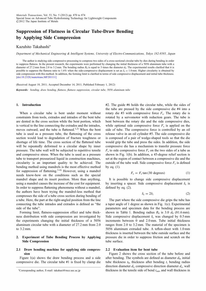
Figure 1(a) shows the draw bending process and a sidecompressive die. The circular tube #1 is fixed by clamp die
#2. The guide #6 holds the circular tube, while the sides ofthe tube are pressed by the side compressive die #4 into arotary die #3 with compressive force Fs. The rotary die isrotated by a servomotor with reduction gears. The tube isbent between the rotary die and the side compressive dies,while optional side compressive force Fc is applied on theside of tube. The compressive force is controlled by an oilrelease valve in an oil cylinder #5. The side compressive dieis composed of a pair of wedge-shaped tools so that the diewould grip the tube and press the sides. In addition, the sidecompressive die has a mechanism to transfer pressure forceFs to side compressive force Fc on the two sides of a tube asshown in Fig. 1(b). In addition, a 45-degree relief section isset at the region of contact between a compressive die and theoutside of the tube wall. Side compressive force Fc is definedby eq. (1).
Fc ¼ Fs tan ð30 degreesÞ ð1ÞIt is possible to change side compressive displacement
by inserting a spacer. Side compressive displacement ¤c isdefined by eq. (2).
¤c ¼ 2¤1 ð2ÞThe part where the side compressive die grips the tube has
a taper angle of 1 degree as shown in Fig. 1(c). Experimentalparameters and specimen data for the bending process areshown in Table 1. Bending radius R0 is 3.0 d0 (81.6mm).Side compressive displacement ¤c was changed by 0.5mmincrements between 0 and 2.0mm. Tube initial thicknessranges from 2.0 to 3.2mm. The material of the specimen is5056 aluminum extruded tube. A teflon-sheet with 1.0mmthickness is inserted between the tube outside surface and thepressure die in order to suppress friction and scratch on thetube surface.
2.2 Evaluation item for bent tubeFigure 2 shows the cross section of the tube before and
after bending. The symbols are defined as diameter d0, initialtube thickness t0, thickness after bending t, bending radiusdirection diameter dr, compressive direction diameter dc, wallthickness in the tensile side of bend tout, and wall thickness in+Corresponding author, E-mail: [email protected]
Materials Transactions, Vol. 53, No. 5 (2012) pp. 870 to 874Special Issue on Advanced Tube Hydroforming Technology for Lightweight Components©2012 The Japan Institute of Metals
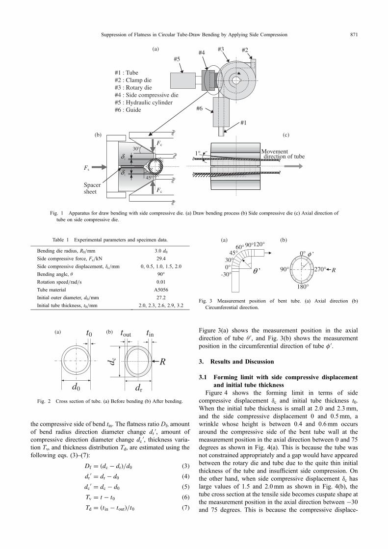
the compressive side of bend tin. The flatness ratio Df, amountof bend radius direction diameter change drB, amount ofcompressive direction diameter change dcB, thickness varia-tion Tv, and thickness distribution Td, are estimated using thefollowing eqs. (3)(7):
Df ¼ ðdc � drÞ=d0 ð3Þdr
0 ¼ dr � d0 ð4Þdc
0 ¼ dc � d0 ð5ÞTv ¼ t� t0 ð6ÞTd ¼ ðtin � toutÞ=t0 ð7Þ
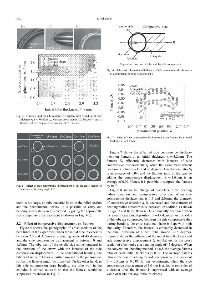
Figure 3(a) shows the measurement position in the axialdirection of tube ªB, and Fig. 3(b) shows the measurementposition in the circumferential direction of tube ºB.
3. Results and Discussion
3.1 Forming limit with side compressive displacementand initial tube thickness
Figure 4 shows the forming limit in terms of sidecompressive displacement ¤c and initial tube thickness t0.When the initial tube thickness is small at 2.0 and 2.3mm,and the side compressive displacement 0 and 0.5mm, awrinkle whose height is between 0.4 and 0.6mm occursaround the compressive side of the bent tube wall at themeasurement position in the axial direction between 0 and 75degrees as shown in Fig. 4(a). This is because the tube wasnot constrained appropriately and a gap would have appearedbetween the rotary die and tube due to the quite thin initialthickness of the tube and insufficient side compression. Onthe other hand, when side compressive displacement ¤c haslarge values of 1.5 and 2.0mm as shown in Fig. 4(b), thetube cross section at the tensile side becomes cuspate shape atthe measurement position in the axial direction between ¹30and 75 degrees. This is because the compressive displace-
(a)
#1
#2 #4#5
#3
#6
#1 : Tube #2 : Clamp die #3 : Rotary die #4 : Side compressive die #5 : Hydraulic cylinder #6 : Guide
δ1
δ1
Fc
Spacer sheet
30° Movement 1°
(b)
direction of tube
Fc
Fs
45°
(c)
Fig. 1 Apparatus for draw bending with side compressive die. (a) Draw bending process (b) Side compressive die (c) Axial direction oftube on side compressive die.
Table 1 Experimental parameters and specimen data.
Bending die radius, R0/mm 3.0 d0Side compressive force, Fc/kN 29.4
Side compressive displacement, ¤c/mm 0, 0.5, 1.0, 1.5, 2.0
Bending angle, ª 90°
Rotation speed/rad/s 0.01
Tube material A5056
Initial outer diameter, d0/mm 27.2
Initial tube thickness, t0/mm 2.0, 2.3, 2.6, 2.9, 3.2
dr
d c R
tout tin
d0
t0(a) (b)
Fig. 2 Cross section of tube. (a) Before bending (b) After bending.
0°-30°
45°120°90°
30°
60°
θ ’
(a) (b)
0°
90°
180°
270° R
φ ’
Fig. 3 Measurement position of bent tube. (a) Axial direction (b)Circumferential direction.
Suppression of Flatness in Circular Tube-Draw Bending by Applying Side Compression 871
ment is too large, so tube material flows to the relief sectionand the phenomenon occurs. It is possible to carry outbending successfully in this method by giving the appropriateside compressive displacement as shown in Fig. 4(c).
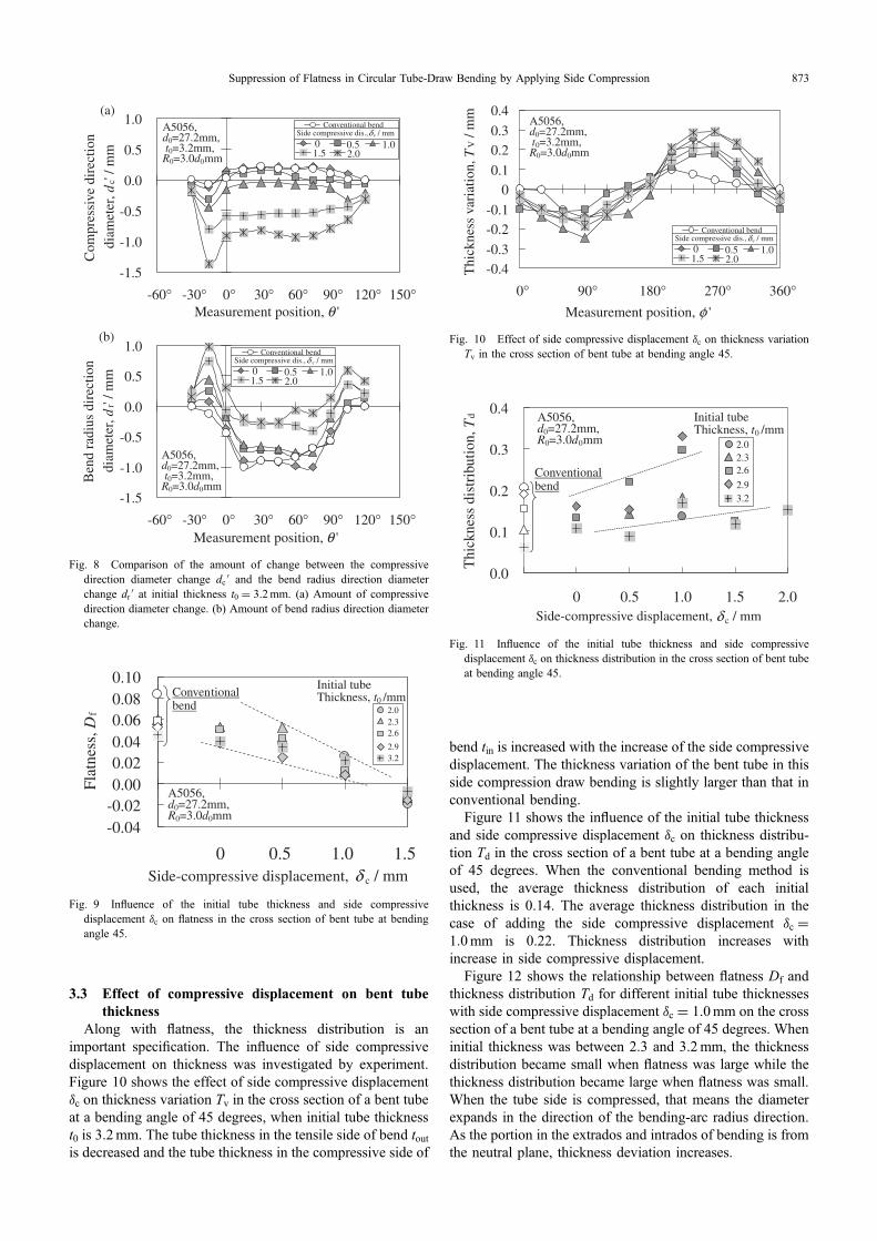
3.2 Effect of compressive displacement on flatnessFigure 5 shows the photographs of cross sections of the
bent tubes in the experiment when the initial tube thickness isbetween 2.0 and 3.2mm at a bending angle of 45 degrees,and the side compressive displacement is between 0 and1.5mm. The tube wall of the tensile side comes outward inthe direction of the arrow with the increase of the sidecompression displacement. In the conventional bending, thetube wall in the extrados is pushed inward by the pressure dieso that the flatness might be propelled. On the other hand, inthis side compression draw bending, the tube wall in theextrados is moved outward so that the flatness would besuppressed as shown in Fig. 6.
Figure 7 shows the effect of side compressive displace-ment on flatness at an initial thickness t0 = 3.2mm. Theflatness Df efficiently decreases with increase of sidecompressive displacement ¤c when the axial measurementposition is between ¹15 and 90 degrees. This flatness ratio Df
is an average of 0.04, and the flatness ratio in the case ofadding the compressive displacement ¤c = 1.0mm is anaverage of 0.02. Hence, it is possible to suppress the flatnessby half.
Figure 8 shows the change of diameters in the bendingradius direction and compressive direction. When sidecompressive displacement is 1.5 and 2.0mm, the diameterof compressive direction dc is decreased and the diameter ofbending radius direction dr is increased. In addition, as shownin Figs. 7 and 8, the flatness Df is eminently decreased whenthe axial measurement position is ¹15 degrees. As the sidesof the tube are compressed between the side compressive diesduring bending, the cross-sectional shape is kept with highcircularity. Therefore, the flatness is eminently decreased inthe axial direction of a bent tube around ¹15 degrees.Figure 9 shows the influence of the initial tube thickness andside compressive displacement ¤c on flatness in the crosssection of a bent tube at a bending angle of 45 degrees. Whenthe conventional bending method is used, the average flatnessratio of each initial thickness is 0.06. The average flatnessratio in the case of adding the side compressive displacement¤c = 0.5mm is 0.038. In this experiment, when the sidecompressive displacement of 1.0mm is added to two sides ofa circular tube, the flatness is suppressed with an averagevalue of 0.016 for any initial thickness.
0.0
0.5
1.0
1.5
2.0
2.0 2.3 2.6 2.9 3.2
Initial tube thickness, t0 / mm
Side
-com
pres
sive
disp
lace
men
t,δ c
/ m
m(c)(b)
Tnsile side
(a)
Compressiveside
Ο : SuccessΔ : Cuspate shapeΧ : Wrinkle
Fig. 4 Forming limit for side compressive displacement ¤c and initial tubethickness t0. (©: Wrinkle, : Cuspate cross-section, : Success)7) (a) ©:Wrinkle (b) : Cuspate cross-section (c) : Success.
t0=2.0mm
δc=0mmConventional
bend
t0=2.6mm
t0=3.2mm
R10mm
WrinkleCuspate
cross-sectionWrinkle
δc=0.5mm δc=1.0mm δc=1.5mm
Fig. 5 Effect of side compressive displacement ¤c on the cross section ofbent tube at bending angle 45°.
δ c=1.0mm
δ c=0mm
Tensile side Compressive side
R
Rotary die
Tube
Expanding direction of tube wall by side compression
Fig. 6 Schematic illustration of influence of side compressive displacementin deformation of cross sectional tube.
-0.10-0.08-0.06-0.04-0.020.000.020.040.06
-60° -30° 0° 30° 60° 90° 120° 150°Measurement position, θ '
Flat
ness
, Df
0 0.5 1.01.5 2.0
Conventional bendSide compressive dis.,δ c / mm
A5056,d0=27.2mm,t0=3.2mm,
R0=3.0d0mm
Fig. 7 Effect of side compressive displacement ¤c on flatness Df at initialthickness t0 = 3.2mm.
K. Takahashi872
3.3 Effect of compressive displacement on bent tubethickness
Along with flatness, the thickness distribution is animportant specification. The influence of side compressivedisplacement on thickness was investigated by experiment.Figure 10 shows the effect of side compressive displacement¤c on thickness variation Tv in the cross section of a bent tubeat a bending angle of 45 degrees, when initial tube thicknesst0 is 3.2mm. The tube thickness in the tensile side of bend toutis decreased and the tube thickness in the compressive side of
bend tin is increased with the increase of the side compressivedisplacement. The thickness variation of the bent tube in thisside compression draw bending is slightly larger than that inconventional bending.
Figure 11 shows the influence of the initial tube thicknessand side compressive displacement ¤c on thickness distribu-tion Td in the cross section of a bent tube at a bending angleof 45 degrees. When the conventional bending method isused, the average thickness distribution of each initialthickness is 0.14. The average thickness distribution in thecase of adding the side compressive displacement ¤c =1.0mm is 0.22. Thickness distribution increases withincrease in side compressive displacement.
Figure 12 shows the relationship between flatness Df andthickness distribution Td for different initial tube thicknesseswith side compressive displacement ¤c = 1.0mm on the crosssection of a bent tube at a bending angle of 45 degrees. Wheninitial thickness was between 2.3 and 3.2mm, the thicknessdistribution became small when flatness was large while thethickness distribution became large when flatness was small.When the tube side is compressed, that means the diameterexpands in the direction of the bending-arc radius direction.As the portion in the extrados and intrados of bending is fromthe neutral plane, thickness deviation increases.
-1.5
-1.0
-0.5
0.0
0.5
1.0
-60° -30° 0° 30° 60° 90° 120° 150°Measurement position, θ '
Ben
d ra
dius
dir
ectio
ndi
amet
er, d
r'/ m
m
-1.5
-1.0
-0.5
0.0
0.5
1.0
-60° -30° 0° 30° 60° 90° 120° 150°Measurement position, θ '
Com
pres
sive
dir
ectio
ndi
amet
er, d
c' / m
mA5056,d0=27.2mm,t0=3.2mm,
R0=3.0d0mm
A5056,d0=27.2mm,t0=3.2mm,
R0=3.0d0mm
(a)
0 0.5 1.01.5 2.0
Conventional bendSide compressive dis.,δc / mm
0 0.5 1.01.5 2.0
Conventional bendSide compressive dis.,δ c / mm
(b)
Fig. 8 Comparison of the amount of change between the compressivedirection diameter change dcB and the bend radius direction diameterchange drB at initial thickness t0 = 3.2mm. (a) Amount of compressivedirection diameter change. (b) Amount of bend radius direction diameterchange.
-0.04-0.020.000.020.040.060.080.10
0 0.5 1.0 1.5Side-compressive displacement, δ c / mm
Flat
ness
, Df
Conventionalbend
Initial tube Thickness, t0 /mm
2.02.32.6
2.93.2
A5056,d0=27.2mm,R0=3.0d0mm
Fig. 9 Influence of the initial tube thickness and side compressivedisplacement ¤c on flatness in the cross section of bent tube at bendingangle 45.
-0.4-0.3
-0.2-0.1
00.1
0.20.3
0.4
0° 90° 180° 270° 360°Measurement position, φ '
Thi
ckne
ss v
aria
tion,
TV /
mm A5056,
d0=27.2mm,t0=3.2mm,R0=3.0d0mm
0 0.5 1.01.5 2.0
Conventional bendSide compressive dis.,δc / mm
Fig. 10 Effect of side compressive displacement ¤c on thickness variationTv in the cross section of bent tube at bending angle 45.
0.0
0.1
0.2
0.3
0.4
2.01.51.00.50Side-compressive displacement, δ c / mm
Thi
ckne
ss d
istr
ibut
ion,
Td
Conventionalbend
2.02.32.6
2.93.2
Initial tube Thickness, t0 /mm
A5056, d0=27.2mm, R0=3.0d0mm
Fig. 11 Influence of the initial tube thickness and side compressivedisplacement ¤c on thickness distribution in the cross section of bent tubeat bending angle 45.
Suppression of Flatness in Circular Tube-Draw Bending by Applying Side Compression 873
3.4 Improvement in circularity of bent tubeThe influence of side compression on the circularity of a
bent tube was investigated. Table 2 shows the effect of sidecompressive displacement on the circularity of a bent tube ata bending angle of 45 degrees. The circularity value wascalculated by dividing the difference between the maximumtube radius and minimum tube radius by the initial tuberadius. The circularity of the bent tube was measured by athree-dimensional measurement machine. When the initialthickness of a circular tube is between 2.0 and 3.2mm andthe compressive displacement of 1.0mm is added to thecircular tube, an average 4.6% circularity can be obtained.
4. Conclusions
(1) When side compression is added to two sides of atube, the diameter in the direction of the side compressiondecreases and the diameter in the direction of the bendingradius increases, so the flatness is suppressed. It is possible to
suppress the flatness to 1.6% in this experiment when sidecompressive displacement is set as ¤c = 1.0mm, which is3.6% of the tube diameter. Higher circularity is obtained byside compression with this new method.
(2) The effects of the initial thickness of the tube andthe forming limit in the proposed side compression drawbending are clarified. When the side compressive displace-ment was small, wrinkle occurred in the tube. When theside compressive displacement was large, the tensile side ofthe cross section of the tube became cuspate shape. Theappropriate compressive displacement is 1.0mm for a tubediameter of 27.2mm in this experiment.
(3) When side compression is added, the flatness issuppressed more than in conventional bending, while thechange of thickness distribution becomes large.
REFERENCES
1) J. Endo and T. Murota: J. Jpn. Soc. Technol. Plast. 27 (1986) 201207.2) S. Aizu: Technol. Press 4 (1966) 7580.3) K. Takahashi and M. Murata: J. JILM 57 (2007) 479486.4) K. Takahashi and M. Murata: J. JILM 56 (2006) 283289.5) K. Takahashi, T. Kuboki, M. Murata and K. Yano: Steel Res. 79 (2008)
241248.6) K. Takahashi, T. Kuboki, M. Murata and K. Yano: J. Jpn. Soc. Technol.
Plast. 49 (2008) 896900.7) K. Takahashi, T. Kuboki and M. Murata: Proc. 5th Int. Conf. on Tube
Hydroforming TUBEHYDRO2011 (2011) pp. 125128.
A5056,d0=27.2mm, R0=3.0d0mm δc =1.0mm
Initial tube Thickness, t0 /mm
0
0.1
0.2
0.3
0.4
0.5
0.6
0.060.050.040.030.020.010.00
Flatness, Df
Thi
ckne
ss d
istr
ibut
ion,
Td
2.62.93.2
2.3
Fig. 12 Relationship between flatness Df and thickness distribution Td fordifferent initial tube thicknesses with side compressive displacement¤c = 1.0mm on the cross section of bent tube at bending angle 45.
Table 2 Effect of side compression displacement on circularity of benttube.
Circularity (%) (®: No measurement)
Initial tube thickness/mm
2.0 2.3 2.6 2.9 3.2
Compressivedisplacement
¤c/mm
Conventional 8.5 6.7 6.8 6.0 4.6
0 ® ® 7.5 5.1 4.9
0.5 ® 7.1 5.0 3.7 3.9
1.0 4.0 5.7 4.6 5.4 3.2
1.5 ® ® 7.4 ® 4.9
K. Takahashi874