Suppression of dynamic-stall vortices over pitching airfoils by leading-edge suction
9
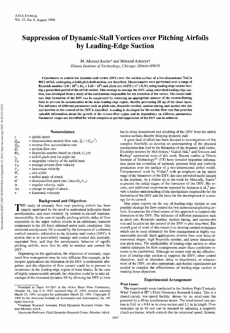
AIAA JOURNAL Vol. 32, No. 8, August 1994 Suppression of Dynamic-Stall Vortices over Pitching Airfoils by Leading-Edge Suction M. Ahsanul Karim* and Mukund Acharyat Illinois Institute of Technology, Chicago, Illinois 60616 Experiments to control the dynamic-stall vortex (DSV) over the suction surface of a two-dimensional NACA 0012 airfoil, undergoing a hold-pitch-hold motion, are described. Measurements were performed over a range of Reynolds number (3.0 x 10 4 < Re c < 1.18 x 10 5 ) and pitch rate (0.072 < oc + < 0.31), using leading-edge suction dur- ing a prescribed period of the airfoil motion. This strategy to manage the DSV, using controlled leading-edge suc- tion, was developed from a study of the mechanisms responsible for the evolution of the vortex. The results indi- cate that formation of the DSV can be suppressed by removing an appropriate amount of the reverse-flowing fluid to prevent its accumulation in the near-leading-edge region, thereby preventing lift up of the shear layer. The influence of different parameters such as pitch rate, Reynolds number, suction timing, and suction-slot size and location on the control of the DSV is described. A scaling is developed for the suction flow rate that provides valuable information about the growth of the reverse-flow region and its dependency on different parameters. Parameter ranges are identified for which complete or partial suppression of the DSV can be achieved. Nomenclature c = airfoil chord Q nd = dimensionless suction flow rate, Q s / (U^c ) Qrt = reverse-flow accumulation rate Q s = suction flow rate Re c = Reynolds number based on chord, U^c/v t p = airfoil pitch time for angle Aoc Up = tangential velocity of the airfoil nose Urf = average reverse-flow velocity f/oo = freestream velocity W s = slot width a - airfoil angle of attack oc + = dimensionless pitch rate, (Accc)/(f p £/„<,) d = angular velocity, rad/s Aoc = change in angle of attack v = kinematic viscosity Background and Objectives T HE study of unsteady flow over pitching airfoils has been largely motivated by the need to understand helicopter-blade aerodynamics, and more recently, by interest in aircraft superma- neuverability. In the case of rapidly pitching airfoils, delay of flow separation on the upper surface results in an additional, transient component to the lift force obtained under static conditions. This increased aerodynamic lift is caused by the formation of a coherent vortical structure, referred to as the dynamic-stall vortex (DSV). A system that is to successfully manage and control this unsteady, separated flow, and thus the aerodynamic behavior of rapidly pitching airfoils, must first be able to monitor and control the DSV. Depending on the application, the objectives of unsteady, sepa- rated flow management may be very different. For example, in he- licopter applications the formation of the DSV is undesirable alto- gether, and the objective of flow control could be to prevent its occurrence in the leading-edge region of rotor blades. In the case of highly maneuverable aircraft, the objective could be to take ad- vantage of the increased dynamic lift by allowing the DSV to form Presented as Paper 93-3267 at the AIAA Shear Flow Conference, Orlando, FL, July 6-9, 1993; received May 25, 1993; revision received March 25, 1994; accepted for publication March 29, 1994. Copyright © 1994 by the American Institute of Aeronautics and Astronautics, Inc. All rights reserved. ^Graduate Research Assistant, Fluid Dynamics Research Center. Stu- dent Member AIAA. t Associate Professor, Fluid Dynamics Research Center. Member AIAA. but to delay detachment and shedding of the DSV from the airfoil suction surface, thereby delaying dynamic stall. A great deal of effort has been devoted to investigations of this complex flowfield, to develop an understanding of the physical mechanisms that lead to the formation of the dynamic-stall vortex. Excellent reviews by McCroskey, 1 Gad-el-Hak, 2 and Ericsson and Reding 3 summarize most of this work. Recent studies at Illinois Institute of Technology 4 ' 5 (IIT) have revealed important informa- tion about the evolution of unsteady pressure field and vorticity production over the surface of a two-dimensional airfoil model. Computational work by Visbal, 6 with an emphasis on the initial stage of the formation of the DSV, has also provided useful insight to the problem. As a follow up to the work by Metwally, Karim 7 examined the initial stages of the formation of the DSV. His re- sults, and additional experiments reported by Acharya et al., 8 pro- vide a further understanding of the mechanisms responsible for the formation of the DSV and the basis for the development of a strat- egy for its control. This paper reports on the use of leading-edge suction as one possible strategy for flow control for two-dimensional pitching air- foils. It examines the effectiveness of this approach to suppress the formation of the DSV. The influence of different parameters such as pitch rate, Reynolds number, suction timing, and suction-slot size and location on the control of the DSV is also described. The overall goal of work of this nature is to develop control techniques which can be used ultimately for flow management in highly ma- neuverable aircraft. Such applications involve flow over three-di- mensional shapes, high Reynolds number, and lower dimension- less pitch rates. The applicability of leading-edge suction or other control strategies for flow management under these conditions re- mains to be established. Although we report only on the effective- ness of leading-edge suction to suppress the DSV, other control objectives, such as alteration, delay in detachment, or enhance- ment of the DSV, are also appropriate, and further experiments are needed to examine the effectiveness of leading-edge suction in meeting these objectives. Experimental Arrangement Wind Tunnel The experiments were conducted in the Andrew Fejer Unsteady Wind Tunnel at IIT's Fluid Dynamics Research Center. This is a closed-circuit, low-speed facility, driven by an axial-vane fan powered by a 40-hp synchronous motor. The wind-tunnel test sec- tion is 0.61 m x 0.61 m in cross section and 3.1 m in length. Flow velocities up to 40 m/s can be reached by adjusting a magnetic clutch excitation, which controls the fan rotational speed. Screens, 1647 Downloaded by RMIT UNIV BUNDOORA on September 22, 2013 | http://arc.aiaa.org | DOI: 10.2514/3.12155
Transcript of Suppression of dynamic-stall vortices over pitching airfoils by leading-edge suction
AIAA JOURNALVol. 32, No. 8, August 1994
Suppression of Dynamic-Stall Vortices over Pitching Airfoilsby Leading-Edge Suction
M. Ahsanul Karim* and Mukund AcharyatIllinois Institute of Technology, Chicago, Illinois 60616
Experiments to control the dynamic-stall vortex (DSV) over the suction surface of a two-dimensional NACA0012 airfoil, undergoing a hold-pitch-hold motion, are described. Measurements were performed over a range ofReynolds number (3.0 x 10⁴ < Rec < 1.18 x 10⁵) and pitch rate (0.072 < oc+ < 0.31), using leading-edge suction dur-ing a prescribed period of the airfoil motion. This strategy to manage the DSV, using controlled leading-edge suc-tion, was developed from a study of the mechanisms responsible for the evolution of the vortex. The results indi-cate that formation of the DSV can be suppressed by removing an appropriate amount of the reverse-flowingfluid to prevent its accumulation in the near-leading-edge region, thereby preventing lift up of the shear layer.The influence of different parameters such as pitch rate, Reynolds number, suction timing, and suction-slot sizeand location on the control of the DSV is described. A scaling is developed for the suction flow rate that providesvaluable information about the growth of the reverse-flow region and its dependency on different parameters.Parameter ranges are identified for which complete or partial suppression of the DSV can be achieved.
Nomenclaturec = airfoil chordQnd = dimensionless suction flow rate, Qs/ (U^c )Qrt = reverse-flow accumulation rateQs = suction flow rateRec = Reynolds number based on chord, U^c/vtp = airfoil pitch time for angle AocUp = tangential velocity of the airfoil noseUrf = average reverse-flow velocityf/oo = freestream velocityWs = slot widtha - airfoil angle of attackoc+ = dimensionless pitch rate, (Accc)/(fp£/„<,)d = angular velocity, rad/sAoc = change in angle of attackv = kinematic viscosity
Background and Objectives
THE study of unsteady flow over pitching airfoils has beenlargely motivated by the need to understand helicopter-blade
aerodynamics, and more recently, by interest in aircraft superma-neuverability. In the case of rapidly pitching airfoils, delay of flowseparation on the upper surface results in an additional, transientcomponent to the lift force obtained under static conditions. Thisincreased aerodynamic lift is caused by the formation of a coherentvortical structure, referred to as the dynamic-stall vortex (DSV). Asystem that is to successfully manage and control this unsteady,separated flow, and thus the aerodynamic behavior of rapidlypitching airfoils, must first be able to monitor and control theDSV.
Depending on the application, the objectives of unsteady, sepa-rated flow management may be very different. For example, in he-licopter applications the formation of the DSV is undesirable alto-gether, and the objective of flow control could be to prevent itsoccurrence in the leading-edge region of rotor blades. In the caseof highly maneuverable aircraft, the objective could be to take ad-vantage of the increased dynamic lift by allowing the DSV to form
Presented as Paper 93-3267 at the AIAA Shear Flow Conference,Orlando, FL, July 6-9, 1993; received May 25, 1993; revision receivedMarch 25, 1994; accepted for publication March 29, 1994. Copyright ©1994 by the American Institute of Aeronautics and Astronautics, Inc. Allrights reserved.
^Graduate Research Assistant, Fluid Dynamics Research Center. Stu-dent Member AIAA.
t Associate Professor, Fluid Dynamics Research Center. Member AIAA.
but to delay detachment and shedding of the DSV from the airfoilsuction surface, thereby delaying dynamic stall.
A great deal of effort has been devoted to investigations of thiscomplex flowfield, to develop an understanding of the physicalmechanisms that lead to the formation of the dynamic-stall vortex.Excellent reviews by McCroskey,1 Gad-el-Hak,2 and Ericsson andReding3 summarize most of this work. Recent studies at IllinoisInstitute of Technology4'5 (IIT) have revealed important informa-tion about the evolution of unsteady pressure field and vorticityproduction over the surface of a two-dimensional airfoil model.Computational work by Visbal,6 with an emphasis on the initialstage of the formation of the DSV, has also provided useful insightto the problem. As a follow up to the work by Metwally, Karim7
examined the initial stages of the formation of the DSV. His re-sults, and additional experiments reported by Acharya et al.,8 pro-vide a further understanding of the mechanisms responsible for theformation of the DSV and the basis for the development of a strat-egy for its control.
This paper reports on the use of leading-edge suction as onepossible strategy for flow control for two-dimensional pitching air-foils. It examines the effectiveness of this approach to suppress theformation of the DSV. The influence of different parameters suchas pitch rate, Reynolds number, suction timing, and suction-slotsize and location on the control of the DSV is also described. Theoverall goal of work of this nature is to develop control techniqueswhich can be used ultimately for flow management in highly ma-neuverable aircraft. Such applications involve flow over three-di-mensional shapes, high Reynolds number, and lower dimension-less pitch rates. The applicability of leading-edge suction or othercontrol strategies for flow management under these conditions re-mains to be established. Although we report only on the effective-ness of leading-edge suction to suppress the DSV, other controlobjectives, such as alteration, delay in detachment, or enhance-ment of the DSV, are also appropriate, and further experiments areneeded to examine the effectiveness of leading-edge suction inmeeting these objectives.
Experimental ArrangementWind Tunnel
The experiments were conducted in the Andrew Fejer UnsteadyWind Tunnel at IIT's Fluid Dynamics Research Center. This is aclosed-circuit, low-speed facility, driven by an axial-vane fanpowered by a 40-hp synchronous motor. The wind-tunnel test sec-tion is 0.61 m x 0.61 m in cross section and 3.1 m in length. Flowvelocities up to 40 m/s can be reached by adjusting a magneticclutch excitation, which controls the fan rotational speed. Screens,
1647
Dow
nloa
ded
by R
MIT
UN
IV B
UN
DO
OR
A o
n Se
ptem
ber
22, 2
013
| http
://ar
c.ai
aa.o
rg |
DO
I: 1
0.25
14/3
.121
55

1648 KARIM AND ACHARYA: VORTICES OVER PITCHING AIRFOILS
honeycombs, and a contraction region upstream of the test sectionyield a turbulence level of 0.03% at the maximum velocity. Con-trolled oscillation of a shutter mechanism, mounted at the down-stream end of the test section, can produce an unsteady flow com-ponent. A controlled, unsteady motion can also be imparted to amodel positioned in the flow.
Airfoil ModelThe airfoil model used for this investigation had an NACA 0012
profile, with a chord length of 30 cm, a thickness of 12% chord,and a span of 60 cm. The model was made hollow to accommodatetubing for surface-pressure measurements and to make room forsuction and blowing chambers. Details of its design and construc-tion are described by Metwally.4
A special feature of the airfoil design provided the ability towithdraw fluid from a spanwise suction slot placed in the near-leading-edge region of the suction surface. A suction chamber witha volume of 50 cm3 was built into the leading-edge region and con-nected to the slot. The slot width could be changed by changing thewidth of an insert. The slot could be located at 2% or 5% of chordfrom the leading edge. In the present investigation, slot widths of0.5 mm and 2 mm were used at the two locations. Another featureof the airfoil, not used in the present experiments, provided theability to introduce a two-dimensional jet into the airfoil wake,through a blowing manifold connected to a spanwise, trailing-edgeslot.
The airfoil was mounted in the horizontal midplane of the testsection, allowing it to pitch about its quarter-chord pivot line. Themodel was driven by a low-inertia, high-torque, servocontrolled dcmotor with an analog servoamplifler. A Schaevitz R30D rotary-variable-differential transformer (RVDT) was used to obtained asignal proportional to the airfoil angular position.
Suction SystemThe airfoil suction chamber was divided into five compartments
to achieve uniform suction across the span. These compartmentswere connected by flexible tubes to a circular distributor locatedinside the airfoil. The distributor was connected to an evacuatedtank located outside the tunnel, through a high-vacuum, direct-act-ing solenoid valve. The trapped-vortex pair (TVP) flow meter de-scribed in the next section was mounted between the distributorand the solenoid valve. The solenoid valve was actuated by signalsfrom the minicomputer to enable suction through the leading-edgeslot at predetermined angles while the airfoil was in motion. Thevacuum tank was evacuated to a specified vacuum level prior toeach experimental run, to obtain the desired suction flow rate.
InstrumentationSmoke-wire flow visualization was used to examine the flow-
field over the pitching airfoil. A 0.1-mm-diam nichrome wire wascoated with oil droplets and heated electrically, causing the drop-lets to vaporize, thereby producing uniform streaklines of smoke.The streak lines passing over the model were illuminated and pho-tographed at the appropriate instant.
A vertical smoke wire, placed one chord length upstream of thenose in the central plane of the airfoil, was used to examine theoverall flowfield. This produced a sheet of streaklines in the cen-tral plane, perpendicular to the airfoil span. To examine the near-wall flow structures, another smoke wire was positioned spanwiseacross the airfoil, at an adjustable height, 0.2-1 mm from the air-foil surface. This produced a spanwise sheet of smoke in the near-wall region over the suction surface. A four-bar mechanismmounted on the airfoil model was used to hold the smoke wire tothe airfoil, allowing it to remain stationary with respect to thepitching airfoil.
A TVP flow meter developed by Mansy and Williams9 was usedto measure the volumetric flow rate of the fluid withdrawn by suc-tion from the near-leading-edge region. The design of this deviceresults in a jet of fluid that issues into a cavity. A pair of counter-rotating vortices produced in the cavity oscillate as the result of aninstability. The oscillation frequency is directly proportional to thevolumetric flow rate of the jet. The pressure difference measured
between the two sides of the flow-meter axis exhibits the same pe-riodicity as the vortex oscillation. The frequency of this differen-tial-pressure signal is related, through calibration, to the flow rateto be measured. A model DP 103 Validyne pressure transducer incombination with a model CD 15 Validyne carrier demodulatorwas used to measure the TVP pressure signal.
A Masscomp minicomputer was used for all of the data acquisi-tion and processing.
Parameter rangesA hold-pitch-hold ramp-up motion of the model at constant ve-
locity was used, covering a range of oc+ between 0.072 and 0.31.The feasibility of leading-edge suction for controlling the dy-namic-stall vortex was examined for airfoil pitchup from 0 to 60deg over a range of chord Reynolds numbers from 30,000 to118,000. Slot locations, slot widths, and ranges of other parame-ters associated with the suction are identified in later sections.
Strategy for Control of the Dynamic-Stall VortexThe control strategy was developed from a study of the initial
stages in the formation of the DSV that identified the principalmechanisms playing a role in this process. Acharya et al.8 providea detailed description of this process and the evolution of the DSV.A few important results are described to develop the basis for thecontrol strategy.
As the airfoil begins its pitching motion, the stagnation pointthat is initially at the nose of the airfoil moves down the pressuresurface, and a strong suction peak develops near the leading edgeon the airfoil suction surface. The region between the stagnationpoint and this leading-edge suction peak experiences a strong, fa-vorable pressure gradient. A concentrated vorticity source locatedin this region introduces negative, or clockwise, vorticity into theflow. For most of the airfoil motion, this source remains betweenthe airfoil nose and 2% of chord on the pressure side. The fluidcontaining this clockwise vorticity is confined to a thin shear layerthat remains close to the surface initially and is transported by theshear layer around the nose and over the suction surface. The shear
view: 12% of chordFig. 1 Flow-visualization records showing development of the DSVover a pitching airfoil; oc+ = 0.31 and Rec = 30,000.
Dow
nloa
ded
by R
MIT
UN
IV B
UN
DO
OR
A o
n Se
ptem
ber
22, 2
013
| http
://ar
c.ai
aa.o
rg |
DO
I: 1
0.25
14/3
.121
55

KARIM AND ACHARYA: VORTICES OVER PITCHING AIRFOILS 1649
<D
40
32
. 24
I"1 16
S30)
0.0 0.2 0.4 0.6 0.8 1.0
Fig. 2 Variation of shear layer liftup angle with pitch rate.
a = 35°Natural Controlled
Fig. 3 Effect of section on flow development during pitchup of air-foil; a+ = 0.15, Rec = 30,000, and Qnd = 0.0127, view shown 67% of air-foiS suction surface.
layer has to negotiate an adverse pressure gradient that existsdownchord of the suction peak location. As the airfoil continues topitch up, this adverse pressure gradient increases, slowing downthe shear layer, and resulting in an accumulation of vorticity nearthe leading edge. This is seen by a thickening of the streaklines inFigs, la and Ib. The effect of the adverse pressure gradient be-comes more severe with increase in the airfoil angle, and eventu-ally builds up to a point where low-momentum fluid close to thesurface slows down sufficiently to produce a region of local re-verse flow (Fig. Ic) over the forward portion of the suction sur-face, between 5% and 10% of the chord. This local, unsteady, re-verse flow plays a crucial role in the formation of the dynamic-stall vortex. The reverse-flow layer, which transports fluid parti-cles upchord along the airfoil suction surface, initially remains thinand close to the surface. As the pitchup continues, the fluid trans-
ported by the reverse flow begins to accumulate in the vicinity ofthe leading edge and forces the shear layer to lift away from theairfoil suction surface (Fig. Id). With increasing accumulation offluid, the shear layer is pushed farther away from the surface anddevelops a kink toward the outer flow (Fig. le). As the airfoilangle increases, the region of accumulated reverse-flowing fluidalso expands in the chordwise direction (Fig. If). Downstream ofthis zone of accumulating, reverse-flow fluid, the pressure contin-ues to increase. This results in a further slowing down of the fluidin the shear layer as additional fluid containing clockwise vorticitycontinues to arrive. At the same time, the shear layer liftup processcontinues upchord, as more reverse-flowing fluid accumulates un-derneath the shear layer. At 26-deg angle of attack (Fig. Ig), a re-circulating zone of reverse-flow fluid is observed. The accumula-tion of clockwise vorticity downstream of this zone, caused by theadverse pressure gradient, combines with the outer flow to initiatean instability or a rollup of the shear layer as seen at 27-deg angleof attack (Fig. Ih). This is the first appearance of the dynamic-stallvortex, formed by the rollup of distributed vorticity in the shearlayer into a large-scale vortical structure. The DSV remains com-pact and stationed over the airfoil surface for a further period, dur-ing which it continues to accumulate vorticity from the shear layer.A very abrupt secondary flow feature—a strong, transverse erup-tion of near-wall fluid, very narrow in streamwise extent and justupstream of the DSV—results in the separation of the DSV fromthe shear layer. After this stage, the DSV detaches from the sur-face, grows very rapidly, and convects downstream.
The accumulation of reverse-flowing fluid in the leading-edgeregion is responsible for the shear layer liftup. Subsequent accu-mulation of vorticity and rollup of the shear layer causes the for-mation of the dynamic-stall vortex. This suggests that preventionor delay of the shear layer liftup might help control the dynamic-stall vortex formation. To eliminate shear layer liftup, we need toprevent accumulation of the reverse-flowing fluid in the leading-edge region. This observation suggested the control strategy forsuppression of the DSV that we examine in this study: remove thereverse-flowing fluid at the same rate as it arrives in the leading-edge region, through a spanwise slot placed appropriately in thesuction surface. Other objectives, such as delaying the detachmentof a formed DSV, can be met by changing the rate at which thisfluid is removed.
Information on the angle at which liftup occurs is important forthe control experiments. The variation of this angle with the di-mensionless pitch rate, plotted in Fig. 2, shows that events in theevolution of the DSV are delayed to higher angles as the pitch rateincreases.
Results of Control ExperimentsEvaluation of Control Strategy
The suction concept just described was tested in experiments, inwhich fluid was withdrawn through a suction slot at a wide range
Dow
nloa
ded
by R
MIT
UN
IV B
UN
DO
OR
A o
n Se
ptem
ber
22, 2
013
| http
://ar
c.ai
aa.o
rg |
DO
I: 1
0.25
14/3
.121
55

1650 KARIM AND ACHARYA: VORTICES OVER PITCHING AIRFOILS
of rates. Figure 3 compares the result of such an experiment at onesuction flow rate, to the flowfield without suction control. Thesephotographs show a view of 67% of the suction surface and weretaken at four different angles of attack, while the airfoil was pitch-ing from 0 to 45 deg with cc+ = 0.15. The spanwise smoke wire waspositioned at the nose, 1 mm from the surface. The dimensionlesssuction flow rate 2nd f°r me controlled case was 0.0127, and suc-tion was initiated at 6-deg angle of attack during pitchup of the air-foil, through a spanwise slot at 2% chord. As discussed in a latersection, this flow rate was found to be the optimum suction rate forthis flow condition and 35-deg angle of attack. The pictures withsuction control show that the shear layer remains close to the sur-face; the negative vorticity produced in the leading-edge regionconvects downstream along the suction surface of the airfoil. Atthe high angles of attack, the smoke streak becomes thicker andtransition to a turbulent state is observed. On the other hand, in thenatural cases with no suction control, a fully grown dynamic-stallvortex is seen over the suction surface of the airfoil. Based on theexperimental results that follow, it is argued that optimum suctionremoves the necessary amount of near-wall fluid through the suc-tion slot to prevent accumulation of reverse-flowing fluid. Shearlayer liftup no longer occurs near the leading edge, thereby pre-venting formation of the DSV. It is this mechanism, rather than re-moval of fluid from the shear layer that flows downchord, that sup-presses the dynamic-stall vortex. The shear layer fluid is notremoved; its agglomeration and rollup into a vortex is prevented.
The results presented in following sections show that formationof the DSV, the shedding of which culminates in dynamic stall,
can be suppressed for a range of flow parameters by removing asmall amount of fluid from the near-wall region. On the basis ofthe experimental evidence, it is reasoned that this suction removesfluid that would otherwise accumulate in the leading-edge region,resulting in liftup of the shear layer. The level of control requiredfor either complete or partial suppression of the DSV is establishedby changing the rate at which fluid is removed from the leading-edge region.
The control strategy is based on the amount of fluid removedfrom the near-wall region rather than the suction pressure level orvelocity at the suction slot. Other parameters, such as suction acti-vation time, deactivation time, and slot location also affect thecontrol process. The influence of these parameters, as well as con-trollability, and limitations with increase in chord Reynolds num-ber and angle of attack are addressed in the following sections.Some scaling properties are also discussed.
Scaling of the Suction Flow RateComplete suppression of the DSV requires that reverse-flowing
fluid be removed from the leading-edge region at a specific rate.An examination of the scaling that governs this suction flow rateprovides a way to validate the concept as well as insight to thegrowth of the reverse-flow region and its dependency on differentparameters. Dimensional analysis, with the variables freestreamvelocity UM a characteristic length, taken to be the chord length c,the angular velocity of the airfoil d, suction flow rate Qs , fluiddensity p and viscosity ji results in three dimensionless groups:
and U^c/v. The last two are the dimensionlessy p^c2,
Fig. 4 Influence of suction flow rate on the development of the DSV; cc+ = 0.15, Rec = 30,000, and a = 35 deg.
Dow
nloa
ded
by R
MIT
UN
IV B
UN
DO
OR
A o
n Se
ptem
ber
22, 2
013
| http
://ar
c.ai
aa.o
rg |
DO
I: 1
0.25
14/3
.121
55

KARIM AND ACHARYA: VORTICES OVER PITCHING AIRFOILS 1651
Fig. 5 State of flowfield over a pitching airfoil; cc+ = 0.15 and a = 35deg for different Rec, with a dimensionless suction flow rate of 0.0127.
pitch rate a+ and chord Reynolds number Rec, respectively. Thecontrol strategy calls for a balance between the rate of suction Qsand the reverse-flow accumulation rate <2rf. A simplified model ofthe near-wall process is used to obtain an expression for the latterand relate the two rates. The dimensionless pitch rate ac/U^ is theratio between a convective time scale c/U^ and the time scale ofthe airfoil motion I/a . For a fixed chord length c and angular ve-locity a, the convection time scale decreases relative to the airfoilmotion time scale as £/«, increases, resulting in an increase in theaccumulation rate. Thus, the accumulation rate is inversely propor-tional to the convective time scale. The rate of growth of the re-verse-flow (viscous) region, on the other hand, is proportional tothe viscous length scale v/Up and convective time scale (c/U^).The ratio of these two scales provides a measure of the accumula-tion rate f/rf of reverse-flowing fluid. Thus the volumetric rate Qdis proportional to LLO/oc), i.e., Up~ca and grf-U^c2. Compar-ison of the two rates grf and Qs yields the appropriate scaling.The control strategy requires that the ratio QSIQ^ remains con-stant for a given dimensionless pitch rate (i.e., a fixed ratio be-tween the convective time scale and the time scale of airfoil mo-tion) and angle of attack. Therefore, the required suction flow ratefor a particular value of oc+ and angle of attack is given by
(g/t/oo) (d/v) = const
QS/.(U^)(6
which is the product of the three dimensionless groups obtained bydimensional analysis. The constant needs to be determined by ex-periment for different pitch rates, Reynolds number, and angle ofattack.
Experimental Determination of the Optimal Flow RateThe effect of varying the suction flow rate over two orders of
magnitude was examined for the conditions of Fig. 3. Suction wasactivated at an angle of 6 deg, and the set of flow-visualizationrecords shown in Fig. 4 was obtained at an angle of 35 deg duringthe pitchup. For values of the dimensionless suction flow rate from0.064 to 0.0123, there is no significant difference in the flowfieldover the airfoil suction surface. Below a rate of 0.0123, ability tosuppress the DSV is progressively degraded. For a suction of0.0101, the development of a vortex is seen near the leading-edgeregion. At 0.000718, the last record in the figure, the flow overthe suction surface resembles the natural case (without suctioncontrol).
If the earlier description of the physical processes is accurate,removing fluid by suction at a rate higher than that needed to pre-vent accumulation of reverse-flowing fluid should not produce anyadditional improvement in the flow state. This should result onlyin removal of some additional fluid with negative vorticity fromthe shear layer. Results for suction rates larger than 0.0127 supportthis argument. Suction at a rate lower than the accumulation rate ofthe reverse-flowing fluid should result in some accumulation in theleading-edge region and, therefore, only a partial suppression ofthe DSV. In addition, partial removal of the reverse-flowing fluidshould slow down the rate of accumulation and lead to a delay inthe vortex formation with a smaller vortex compared to the naturalstate at the same angle of attack. Results for suction rates smallerthan 0.0127 validate this reasoning. Although the accumulationrate is not measured directly, it is logical to argue that for the ex-perimental conditions already described, a suction rate of 0.0127removes reverse-flowing fluid at the accumulation rate and that foreach set of flow conditions, there must be an optimum suction flowrate which prevents any accumulation of reverse-flowing fluid,thereby suppressing the vortex completely. The optimum condi-tions must be defined for a specific control objective, such as com-plete suppression of the vortex. Different objectives, such as par-tial control or delaying the detachment of a formed DSV, wouldresult in different optimum specifications.
Effect of Freestream Velocity and Pitch Rate atDifferent Angles of Attack
Experiments were carried out to examine the influence offreestream velocity and pitch rate on the control of the dynamic-stall vortex at different angles of attack. A 0.5-mm-wide slot, lo-cated at 2% chord, was used. The objective of control was com-
= const
or
(Qs/UOQc2)a+Rec = constFig. 6 State of flowfield over a pitching airfoil; oc+ = 0.072 and a = 35deg for different Rec, with a dimensionless suction flow rate of 0.109.
Dow
nloa
ded
by R
MIT
UN
IV B
UN
DO
OR
A o
n Se
ptem
ber
22, 2
013
| http
://ar
c.ai
aa.o
rg |
DO
I: 1
0.25
14/3
.121
55
1652 KARIM AND ACHARYA: VORTICES OVER PITCHING AIRFOILS
plete suppression of the dynamic-stall vortex. The minimum suc-tion flow rate required to achieve this control was chosen to be theoptimum rate. For all of the experiments described, suction wasactivated at 6-deg angle of attack during pitchup of the airfoil.
Figure 5 shows that suction with Qnd = 0.0127 provides controlat 35 deg, for oc+ = 0.15 over a Reynolds number range of 30,000-118,000. Note that for a fixed value of a+, the product(Qs/U^c ) Rec is independent of U^. The data of Fig. 5 substan-tiate this. Data at a+ - 0.10 for the same conditions also confirmthe scaling argument and model for reverse-flow accumulation,with a higher value (0.0429) for the suction flow rate. Figure 6shows the results at 35 deg for a+ = 0.072 and a Reynolds numberrange of 30,000-88,000. In this case, the dynamic-stall vortex wascompletely suppressed by removing fluid at a rate of 0.109 for arange of Reynolds numbers 30,000-50,000. For the same removalrate, however, the flowfield over the airfoil suction surface showsa degraded effect of suction as the freestream velocity increasesbeyond this value. This effect is first seen at a Reynolds number of53,000, where the dynamic-stall vortex starts developing near theairfoil leading edge. With increase in freestream velocity, the ef-fect grows, and the ability to suppress the DSV decreases. At aReynolds number of 88,000, the DSV extends up to trailing edgeof the airfoil.
The behavior at lower pitch rates is related to early breakdownof the shear layer.7 At lower pitch rates, the flow is closer to qua-sisteady in nature. With the increase in the freestream velocity be-yond a critical value, transition to turbulence in the shear layer al-ters the flow behavior. Since the dynamic-stall vortex is weaker atlower pitch rates, transition and turbulence in the shear layer affectthe flow development at comparatively smaller values of Reynolds
number. On the other hand, at higher pitch rates, unsteady effectsare more dominant, the dynamic-stall vortex is stronger, and theeffects of transition and turbulence in the shear layer on the devel-opment of the DSV are important only at relatively higher Rey-nolds numbers. Once a breakdown of the shear layer occurs, thereverse-flow region becomes substantially thicker, and a largeramount of fluid needs to be removed by suction to achieve com-plete suppression of the DSV. This amount then needs to be in-creased as the freestream velocity increases.
Flow-visualization records and corresponding suction flow ratemeasurements reveal that as long as the unsteady flowfield is notinfluenced by transition and turbulence in the shear layer, controlof the DSV is independent of freestream velocity (or Reynoldsnumber). The magnitude of the favorable, stream wise pressuregradient on the suction surface increases with pitch rate and has ahighly stabilizing effect on the boundary layer. This causes theshear layer and reverse-flow regions to remain thin and movestransition to higher Reynolds number. Thus, as the unsteady effectincreases, the rate of accumulation of reverse-flowing fluid for agiven pitch rate is the same for a wider range of Reynolds number.
In summary, the pitch rate has the primary influence on the un-steady flow behavior and dictates the suction flow rate needed toachieve optimal control at a given angle of attack. As long as thereverse-flow region remains thin, the flow can be controlled by re-moving a small amount of fluid to prevent accumulation in thenear-leading-edge region, and the amount of fluid removed is inde-pendent of the outer flow velocity. As the pitch rate decreases, theReynolds number at which transition to turbulence occurs in theshear layer decreases, the flow structure is altered, and the heightof the reverse-flow region increases at the same angle of attack.
8.00
£6.00
?4.00
2.00
0.00
REGION OFPARTIAL SUPPRESSION
REGION OFCOMPLETE SUPPRESSION
0.00 0.10 0.20 0.30 0.40 0.50
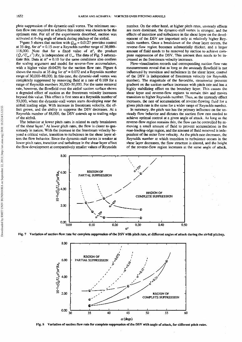
Fig. 7 Variation of suction flow rate for complete suppression of the DSV with pitch rate, at different angles of attack during the airfoil pitchup.
8.00
6.00
I3? 4.00
2.00
0.00
REGION OFPARTIAL SUPPRESSION
REGION OFCOMPLETE SUPPRESSION
30 35 50 55 6040 45
a(degs)Fig. 8 Variation of suction flow rate for complete suppression of the DSV with angle of attack, for different pitch rates.
Dow
nloa
ded
by R
MIT
UN
IV B
UN
DO
OR
A o
n Se
ptem
ber
22, 2
013
| http
://ar
c.ai
aa.o
rg |
DO
I: 1
0.25
14/3
.121
55

KARIM AND ACHARYA: VORTICES OVER PITCHING AIRFOILS 1653
Flow control now depends not only on the pitch rate but also onthe outer velocity (or Reynolds number).
Data were acquired for a few different angles during the pitchupof the airfoil. The flow rates needed for complete suppression of thevortex are plotted against the dimensionless pitch rates in Fig. 7.This representation of the data is useful to study the effect of pitchrate on the control of the dynamic-stall vortex and to provide evi-dence for the validity of the simplified model of the accumulationprocess. The suction flow rate is normalized as (Qs/U^ c ) aRec,using the scaling developed with the model. For a given angle of at-tack (e.g., 35 deg), this product remains constant for a range of di-mensionless pitch rates, as predicted by the model. The extent ofthis range of a+ increases as the angle of attack decreases. As thepitch rate decreases for a given angle of attack, the model eventu-ally breaks down, and the amount of suction required starts to in-crease. At some point, the volumetric rate limit of the suction appa-ratus used in the experiments is reached. Beyond this, only partialsuppression of the DSV is possible, i.e., the control objective is notmet. The range of pitch rates where partial suppression was ob-tained is shown by a broken line on the plot for each angle of attack.Thus, it is possible to define a zone of complete suppression in thisparameter space (shown in the figure by a broken line). An in-creased suction flow rate is required to achieve optimal control asthe pitch rate decreases and the airfoil angle of attack increases.
The suction requirements are shown plotted vs angle of attack inFig. 8 for different dimensionless pitch rates. As the angle of at-tack decreases and pitch rate increases, the suction required forcontrol decreases. Following a line of constant a+, it is possible todetermine the suction requirements during a constant pitch ratemaneuver. To meet the control objective (complete suppression),the suction flow rate needs to be increased as the angle of attackincreases. A broken line once again divides the regions of com-
3.00
plete and partial suppression. As the pitch rate increases, completesuppression can be achieved at higher angle of attack for the samesuction flow rate. The region above the broken line shows the do-main where the DSV can only be partially suppressed, and the ef-fectiveness of control degrades as the Reynolds number increases.
The plots in Fig. 9 show the variation of suction flow rate withReynolds number at two fixed angles of attack for different pitchrates. The range of the Reynolds number where suction control isindependent of freestream velocity (Reynolds number) becomessmaller as the pitch rate decreases or angle of attack increases.
Thus, the experiments establish a range of applicability for theproposed scaling, verify the validity of a simple model for the ac-cumulation of reverse-flow fluid, and provide the ability to predictthe amount of suction required for complete suppression of theDSV over a domain of the primary parameters that influence theprocess.
Effect of Suction Activation and Deactivation TimeTo examine the influence of suction activation time aon on the
control process, flow-visualization records were obtained at 35-deg angle of attack while airfoil was pitching from 0 to 40 deg, fora range of aon with aoff fixed at 38 deg. The rate of suction wasfixed at the optimum value of 0.0127 for the flow conditions (a+ =0.15 and a = 35 deg). The flow development over the airfoil suc-tion surface for aon values of 6, 10, 15, 20, 25, and 30 deg is com-pared with the natural case (no suction) in Fig. 10. Suction can beused to suppress the dynamic-stall vortex completely if activatedbefore the airfoil reaches 20 deg (i.e., aon < 20 deg). Note thatshear layer liftup occurs at about 18 deg for this pitch rate (Fig. 2).
The effect of suction deactivation time on the flow control wasexamined by fixing aon at 6 deg and varying aoff over a range forthe same flow conditions. The results indicate that termination of
2.40
*t* 1.80
•o; 1.20X
0.60
0.00
REGION OFPARTIAL SUPPRESSION
_ +* a ~a°72
(a)a=35°
REGION OFCOMPLETE SUPPRESSION
—— a+=0.10—£
0.00 8.00 32.00 40.0016.00 24.00106xl/Rec
Fig. 9a Variation of suction flow rate for complete suppression of the DSV with Reynolds number, for different pitch rates, a = 35 deg.
*o
H
•aX
o
4.UU
3.20
2.40
1.60
0.80
^^ (b)a=45°\ ^^^^^
REGIONOF © " ^ © ———— © —— a+ = 0.15 — <§)PARTIAL SUPPRESSION /^
^ REGIONOF/ COMPLETE SUPPRESSION
/ 0 E B B B a+-0.31 — B
/ . . . :0.00 ———————————————————————————————————————————————
0.00 8.00 16.00 24.00 32.00 40.
106xl/Rec
Fig. 9b Variation of suction flow rate for complete suppression of the DSV with Reynolds number, for different pitch rates, a = 45 deg.
Dow
nloa
ded
by R
MIT
UN
IV B
UN
DO
OR
A o
n Se
ptem
ber
22, 2
013
| http
://ar
c.ai
aa.o
rg |
DO
I: 1
0.25
14/3
.121
55

1654 KARIM AND ACHARYA: VORTICES OVER PITCHING AIRFOILS
Fig. 10 Effect of suction activation time on flow development duringairfoil pitchup; oc+ = 0.15, Rec = 30,000, Qnd = 0.0127, a = 35 deg, andocoff = 38deg.
suction control before the angle of attack at which control isneeded results in incomplete suppression of the vortex. This be-havior of the unsteady flow suggests that once the suction is initi-ated, it must be applied continuously, as long as the control is de-sired. Terminating suction control results in the immediateformation of the dynamic-stall vortex.
Complete suppression of the dynamic-stall vortex therefore re-quires that two conditions on the suction timing be satisfied: 1)suction activation should be prior to the angle at which the shearlayer liftup occurs and 2) suction control should be continued aslong as control is desired. However, the selection of the suctionflow rate depends on the maximum angle at which the flow controlis desired and on the rate at which the airfoil is pitching.
Effect of Width and Position of the Suction SlotThe suction slot width was varied by a factor of four and the slot
location changed from 2 to 5% chord. Figure 11 shows two visual-izations of the flow at 35-deg angle of attack for Rec = 30,000, a+
= 0.15, and slot widths of 0.5 and 2 mm, respectively. In bothcases the suction slot was located at 2% of the airfoil chord. Thesepictures show no significant difference in the flowfield. All of themeasurements made indicate that the volume rate of suction, notthe suction velocity, is the important control parameter.
Experiments were conducted for slot locations between 2 and5% of airfoil chord for the same flow conditions as previously de-scribed. No significant differences were observed over this rangeof slot location. It is argued that the slot location is not critical, aslong as it is in a region where reverse-flowing fluid can be re-moved.
Magnitude of SuctionTo assess the control technique, some measure of the energy ex-
pended in its implementation is needed. The dimensionless suctionflow rate Qnd compares the suction flow rate Qs with a representa-tive flux of oncoming fluid U^c2 and provides a measure to assessthe amount of fluid removed. For complete suppression of theDSV over the range of pitch rates, chord Reynolds numbers, and
Fig. 11 Effect of suction slot width on suppression of the DSV; slotlocation 2% chord, a+ = 0.15, Rec = 30,000, Qnd = 0.0127, a = 35 deg,aon = 6 de8»and aoff =
angles of attack examined, the ratio (Qs/U^c ) was of the orderof 0.01. Other control strategies suggested have been suggested,with similar results. Visbal's6 computations showed that suctionwith a velocity 4% of the freestream velocity, applied uniformlybetween the nose and 15% of chord, could suppress the DSV at 36-deg angle of attack at a dimensionless pitch rate of 0.6. When thesuction application was concentrated in a region between the noseand 2% of chord, the suction velocity required to suppress the vor-tex increased to 10% of the freestream velocity. Yang et al.10 de-scribe control of the DSV using modulated suction and injection atthe airfoil surface, over an area that varies with the dimensionlesspitch rate. Their computational results show a delay in the onset ofdynamic stall, with a corresponding increase in lift and reductionof drag.
Characteristic Length ScaleIt is important to note that the events influencing the formation
and control of the DSV occur in the leading-edge region of the air-foil and that the mechanisms described can be strongly influencedby the airfoil geometry in this region. Therefore, a length scalecharacteristic of this region, such as leading-edge radius, is in allprobability the appropriate scale to use, rather than the airfoilchord, when describing the Reynolds-number effects. However,since a single airfoil model was used in these studies, the twoscales are related by a constant factor, allowing the use of chordReynolds number in interpreting the results.
ConclusionsThese experiments indicate that controlled leading-edge suction
can be used in principle as an effective tool to control or modifythe dynamic-stall vortex over the suction surface of a two-dimen-sional, pitching airfoil. The suction required for complete suppres-sion of the vortex depends on pitch rate, airfoil angle of attack, andReynolds number. Complete suppression is possible over a defineddomain of parameter space. The pitch rate is the primary factorthat determines suction requirements. The Reynolds number be-comes an increasingly important factor as the pitch rate decreases,and transition to turbulence in the shear layer increases the com-plexity of the flowfield. Under these conditions, the limitations de-scribed restrict the use of leading-edge suction for a complete sup-pression of the DSV. However, when the objective of flow controlis partial suppression, leading-edge suction can be used effectivelyover a wider domain of parameters. This may be a useful ap-proach, for instance, to delay detachment of a formed DSV. Sincethe formation of the DSV results in increased lift, a delay in the de-tachment of the DSV could be utilized to get increased lift for alonger period of time and to push the occurrence of dynamic stallto higher angles of attack. Metwally4 showed that for one set ofconditions he examined, suction control delayed the events in the
Dow
nloa
ded
by R
MIT
UN
IV B
UN
DO
OR
A o
n Se
ptem
ber
22, 2
013
| http
://ar
c.ai
aa.o
rg |
DO
I: 1
0.25
14/3
.121
55

KARIM AND ACHARYA: VORTICES OVER PITCHING AIRFOILS 1655
DS V formation and detachment by 40% of the pitchup period rela-tive to the natural case.
AcknowledgmentThe authors would like to acknowledge the support of the U.S.
Air Force Office of Scientific Research, under Grant 90-0173,monitored by Daniel B. Fant.
References^cCroskey, W. J., "Unsteady Airfoils," Annual Review of Fluid Me-
chanics, Vol. 14, 1982, pp. 285-311.2Gad-el-Hak, M., "Unsteady Separation on Lifting Surfaces," Applied
Mechanics Review, Vol. 40, No. 4, 1987, pp. 441^52.3Ericsson, L. E., and Reding, J. P., "Fluid Dynamics of Unsteady Sepa-
rated Flow. Part II. Lifting Surfaces," Progress in Aerospace Sciences,Vol. 24, 1987, pp. 249-356.
4Metwally, M. H., "Investigation and Control of the Unsteady Flow
Over a Pitching Airfoil," Ph.D. Thesis, Mechanical and Aerospace Engi-neering Dept, Illinois Inst. of Technology, Chicago, IL, Dec. 1990.
5Acharya, M., and Metwally, M. H., "Unsteady Pressure Field and Vor-ticity Production over a Pitching Airfoil," AIAA Journal, Vol. 30, No. 2,1992, pp. 403-411.
6Visbal, M. R., "On the Formation and Control of the Dynamic StallVortex on a Pitching Airfoil," AIAA Paper 91-0006, Jan. 1991.
7Karim, M. A., "Experimental Investigation of the Formation and Con-trol of the Dynamic-Stall Vortex Over a Pitching Airfoil," M.S. Thesis,Mechanical and Aerospace Engineering Dept., Illinois Institute of Tech-nology, Chicago, IL, Dec. 1992.
8Acharya, M., Karim M. A., and Metwally M. H., "Development of theDynamic-Stall Vortex over a Pitching Airfoil," Journal of Fluid Mechan-ics (submitted for publication).
9Mansy, H., and Williams, D. R., "Flow Meter Based On The TrappedVortex Pair Fluidic Oscillator," Review of Scientific Instruments, Vol. 60,No. 5, 1989, pp. 935-938.
10Yang, J., Ghia, K. N., Ghia, U., and Osswald, G. A., "Management ofDynamic Stall Phenomenon Through Active Control of Unsteady Separa-tion," AIAA Paper 93-3284, July 1993.
Proceedings from the 1International Council of
September 20-25,1992 • Beijing, Peo|
The ICAS '92 conference proceedings offer 2science and technology. Convenientlytopics:airtrafficcontrol •and applications • maintenance systems,
. , . 4 t. . t t . . Iairframe integration • aircraft design concepts • passenger and crew safety • aeroelastic analysis • performance,stability and control • navigation • faulttolerant systems • fatigue • structural dynamics and control • aerodynamics• noise • combustion • wind tunnel technology • structural testing • high incidence and vortex flows • impactbehavior of composites • aircraft operations and human factors • system safety and dynamics • fatigue and damagetolerance • hypersonic aircraft • avionics • supersonic and hypersonic flow • crew activity and analysis • simulatorsand man-machine integration • CAD/CAM and CIM, and much more
1992, 2-vol set, 2,200 pp, paper, ISBN 1-56347-046-2, AIAA Members $130, Nonmembers $150, Order #: 18-ICAS(830)
Place your order today! Call 1 -800/682-AIAA
American Institute of Aeronautics and Astronautics
Publications Customer Service, 9 Jay Could Ct., P.O. Box 753, Waldorf, MD 20604FAX 301/843-0159 Phone 1 -800/682-2422 8 a.m. - 5 p.m. Eastern
Sales Tax: CA residents, 8.25%; DC, 6%. For shipping and handling add $4.75 for 1 -4 books (callfor rates for higher quantities). Orders under $100.00 must be prepaid. Foreign orders must beprepaid and include a $20.00 postal surcharge. Please allow 4 weeks for delivery. Prices aresubject to change without notice. Returns will be accepted within 30 days. Non-U.S. residentsare responsible for payment of any taxes required by their government.
Dow
nloa
ded
by R
MIT
UN
IV B
UN
DO
OR
A o
n Se
ptem
ber
22, 2
013
| http
://ar
c.ai
aa.o
rg |
DO
I: 1
0.25
14/3
.121
55