Supported Equipment Manual - connectrf.com · The PPT 8840 has a Pocket PC operating system or ......
83
Supported Equipment Manual for the 8840 device manufactured by Symbol Technologies
Transcript of Supported Equipment Manual - connectrf.com · The PPT 8840 has a Pocket PC operating system or ......

Supported Equipment Manual for the 8840 device manufactured by Symbol Technologies

Copyright © 1996 - 2006 by Connect, Inc.
All rights reserved. This document may not be reproduced in full or in part, in any form, without prior written permission of Connect, Inc., 1701 Quincy Avenue, Suites 5 & 6, Naperville, IL 60540.
Connect, Inc. makes no representation or warranties with respect to the contents of this document and specifically disclaims any implied warranties of merchantability or fitness for any particular purpose. Further, Connect, Inc. reserves the right to revise this publication and to make changes to it from time to time without obligation to notify any person or organization of such revision or changes.
Trademarks
OpenAir Linux™, OpenAir Windows™, OpenAir 400™, PowerNet AirLinc™, PowerNet Twin Client™, and PowerNet OpenAir™ are trademarks of Connect, Inc.
Other product names mentioned in this manual may be trademarks or registered trademarks of their respective companies and are hereby acknowledged. Production
This manual was written, edited, and produced by: Connect, Inc. 1701 Quincy Avenue, Suites 5 & 6 Naperville, IL 60540 www.connectrf.com
Printed in the U.S.A. Please let us know about any errors in this document at: http://207.241.78.223/isoxpert/calltrak.nsf/WebTracking?OpenForm

Table of Contents
Chapter 1 • Introduction............................................................................................. 1-1
Release Note……………… ...........................................................................................1-1 Description………………… ..........................................................................................1-1 Pictures……………………………..................................................................................1-1 Setup Requirements…….. ...........................................................................................1-2 Accessories……………….............................................................................................1-2 Synchronization Tools….. ...........................................................................................1-2
Chapter 2 • Terminal Setup........................................................................................ 2-1
Downloading from the WEB........................................................................................2-1 Running Setup from a Download File ........................................................................2-1 Installation………………… ...........................................................................................2-2 Running the Manager………….. ..................................................................................2-4 Quick Start…………………...........................................................................................2-5
Configuring the Manager....................................................................................2-5 Booting the Terminal ........................................................................................2-13 Configuring the 8840 Terminal for Download...................................................2-13 Starting a Telnet Session .................................................................................2-14
Standard Setup…………….........................................................................................2-15 Setup Using Twin Client Manager ....................................................................2-15 Importing Custom Configurations.....................................................................2-21 Terminal Setup Using Twin Client Menus ........................................................2-22 Authorizing PowerNet.......................................................................................2-24
Software Management……........................................................................................2-30 Airloader Auto-Configuration ............................................................................2-30 Mobile Device Manager (MDM) Features.........................................................2-35 Sending Program and Configuration Files to the Terminal...............................2-45
Chapter 3 • Keypad Configuration ............................................................................ 3-1
16-key Diagram……………...........................................................................................3-1 16-key Table……………………... ..................................................................................3-2 9-key Diagram…………….............................................................................................3-4 9-key Table…………………...........................................................................................3-4
Chapter 4 • Error Message Resolution Guide .......................................................... 4-1
Supported Equipment Manual • March, 2006 iii

____________________________________________________________________________________
This page is intenionally blank.
iv Supported Equipment Manual • March, 2006

Chapter 1 • Introduction
Release Note The Symbol 8846 requires a minimum level of 4.2 of the OS to run correctly.
Description The PPT 8840 has a Pocket PC operating system or Microsoft® Windows® CE 4.1 (CE .NET) embedded operating system, an Intel® XscaleTM PXA250 CPU, and 32MB RAM/ 32MB ROM memory. This terminal has wireless networking based on the standard IEEE 802.11b (WLAN) or BluetoothTM (WPAN). The keypad comes in the standard version (9-key) and 16-key with power button version, and has a transflective color TFT-LCD display, with 65K colors, and is 240 (W) x 320 (L) (QVGA size). Power characteristics include a rechargeable/replaceable lithium-ion battery and a rechargeable Ni-MH backup battery, (15mAh, 2.4V, 2 cells). Additional features include Type II CF Card Slot, Internal antenna, LED backlight, AirBEAM® support, Glass analog resistive touch panel, Multi-language support, Laser bar code scanning, and Speaker and Microphone audio. For more information, visit www.symbol.com.
Pictures
Supported Equipment Manual • March, 2006 1-1

Introduction
Setup Requirements Installation of PowerNet Twin Client requires, at a minimum, the following: • A Pentium-class processor • 32 MB of RAM • 10 MB of free hard disk space available • Microsoft Windows Pocket PC or CE 4.1 (CE .NET) operating system • ActiveSync needs to be installed on the PC before downloading files to the terminal.
For instructions, go to www.MSDN.Microsoft.com.
Accessories The following accessories are available for the 8800:
• Spare Lithium-Ion Rechargeable Battery • Larger Capacity Lithium-Ion Rechargeable Battery Kit • 1-Slot Serial Charging Cradle • 4-Slot Ethernet Cradle • 4-Slot Serial Cradle • Holster(s) and Case • Stylus or Tethered Stylus • Serial Charging Cable • Universal Cable Cup for Attachable Cables
o Attachable Power Supply and Line Cord o Printer Cable Options o DEX Cable o Auto-Charging Cable o USB Cable
• Pistol Grip Handle • Magnetic Stripe Reader • UBC Adapter • Vehicle Cradle
Synchronization Tools
Pocket PC devices require at least version 3.1 of ActiveSync for desktop synchronization and communication. ActiveSync 3.1 is freely downloadable from the Microsoft web site, at www.microsoft.com/pocketpc/downloads/activesync.asp.
Supported Equipment Manual • March, 2006 1-2

Chapter 2 • Terminal Setup
Downloading from the WEB The PowerNet Twin Client software package can be downloaded from the Connect web site at http://www.connectrf.com. Click on Partner Services and then click on Software Downloads. Select the file named PowerNet Twin Client for Symbol.
Running Setup from a Download File The downloaded file is a compressed archive. After extraction using a utility such as WinZip or PKWARE, folders are created on the hard disk as shown in the following figure.
Click on the Disk1 folder to view the files as shown in the following figure.
Click on the Setup application and proceed to the section entitled Installation for further instructions.
Supported Equipment Manual • March, 2006 2-1

Terminal Setup
Installation The InstallShield wizard runs and presents the following screen.
Click on Next to begin the installation process.
To change the default Destination Location, click on Browse and select a location. Then click on Next.
Supported Equipment Manual • March, 2006 2-2

Installation
The default folder is PowerNet. This default may be changed either by selecting an existing program group or by typing in a new name at the prompt. Then click on Next.
Read the warning. Select Yes to continue with the installation, or No to close the setup.
Supported Equipment Manual • March, 2006 2-3

Terminal Setup
When the installation is complete, reboot the system to initialize the Twin Client software.
a. To reboot the system immediately, click on Finish.
b. To reboot later, click on the option to restart the computer later, and then click on Finish.
Running the Manager The PowerNet Twin Client Manager is the utility that manages the terminal software and configurations.
Select Start, Programs, PowerNet, and Twin Client Manager. The PowerNet Twin Client Manager screen appears as shown in the following figure. This is the administrator's main screen, and all functions are accessed from its menu bar, toolbar, and tabs.
Menu Bar The menu bar provides access to the functions used to configure the terminals and manage their software.
Supported Equipment Manual • March, 2006 2-4

Quick Start
Toolbar Found under the menu bar, the toolbar provides shortcuts to major features. The toolbar can be turned on or off by changing the Toolbar parameter found on the View menu. The shortcuts available from the toolbar are as follows:
Create a new terminal configuration.
Open an existing terminal configuration.
Save the current terminal configuration.
Download the configuration to the terminal.
Download software to the terminal.
Configure terminals automatically over the wireless network.
View the PowerNet Twin Client Manager version.
The PowerNet Twin Client Manager is now successfully installed and ready for use. The section below entitled Quick Start provides detailed instructions for quickly configuring the terminal and starting a Telnet session.
Quick Start This section describes how to prepare the Twin Client Manager and the Symbol terminal for a Telnet session with the host. Following an initial serial download, the terminal software and configuration are managed automatically over the wireless network.
Note: Symbol terminals are normally delivered with Symbol files pre-installed. However, if the terminal does not have those files installed refer to the section entitled Configuring the 8840 Terminal for Download before proceeding.
Configuring the Manager The first step is to configure the Twin Client Manager to meet site-specific requirements, and then prepare it for the automatic management of the terminal software and IP addresses. This simple procedure will require only a few minutes to complete.
Setting the Emulation
Click on Start, Programs, PowerNet, and Twin Client Manager. Select the Settings menu, as shown below.
Supported Equipment Manual • March, 2006 2-5
Terminal Setup
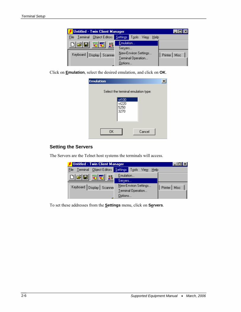
Click on Emulation, select the desired emulation, and click on OK.
Setting the Servers
The Servers are the Telnet host systems the terminals will access.
To set these addresses from the Settings menu, click on Servers.
Supported Equipment Manual • March, 2006 2-6

Quick Start
Then click on Add. Enter the server name, IP address, IP port (normally 23 for Telnet servers), and terminal type. Then click on OK.
Repeat this step for each Telnet server the terminals are required to access. If an error is made in the server name, IP address, IP port number, or terminal emulation type, click on the line that is in error and then click on the Edit button to make the corrections. Use the Load button if you want to load an .svr file. Use the Save As button if you want to save your file as an .svr file.
Terminal AirLoader and AirBEAM Operations
In the Twin Client menu under Settings, choose Terminal Operation.
Supported Equipment Manual • March, 2006 2-7

Terminal Setup
Run AirLoader on terminal can be selected, the AirLoader server IP address can be entered, and the Windows CE options of Run application at startup, Hide task bar, and Use GUI menus and screens can be selected, as shown below. Click on OK.
See the AirBEAM Operation section in the Symbol Twin Client manual for instructions on the AirBEAM option in this screen.
Setting Terminal Model and COM Port
The terminal model is 8840, and the default serial connection is through COM1. To select a specific Symbol terminal model and keypad, or to change the COM port assignment, click on the Options menu as shown.
To maintain compatibility with existing Symbol Telnet client keyboard layouts, a specific terminal model and keypad must be selected from the Terminal Model window.
Supported Equipment Manual • March, 2006 2-8
Quick Start
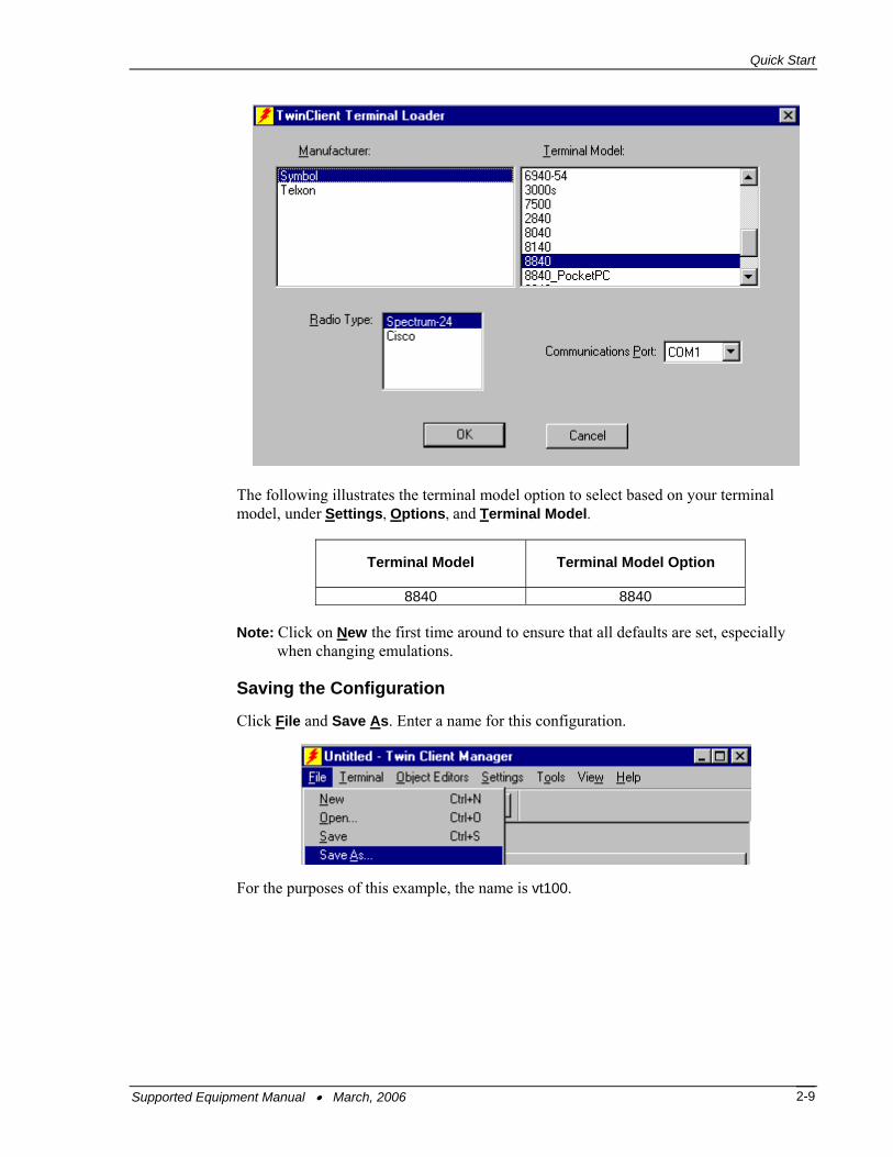
The following illustrates the terminal model option to select based on your terminal model, under Settings, Options, and Terminal Model.
Terminal Model Terminal Model Option
8840 8840 Note: Click on New the first time around to ensure that all defaults are set, especially when changing emulations.
Saving the Configuration
Click File and Save As. Enter a name for this configuration.
For the purposes of this example, the name is vt100.
Supported Equipment Manual • March, 2006 2-9

Terminal Setup
Setting Airloader Auto-Configuration
The configuration download and IP address assignment for each terminal will take place automatically by setting the Airloader Auto-Configuration options.
Click on the Airloader option in the Tools menu.
Note: If the Airloader Auto-Configuration window does not display the options, click on the Advanced<< button.
If multiple network adapters are installed on the PC, ensure that the desired network adapter is selected. The adapter selection can be changed by clicking on the Change button.
Supported Equipment Manual • March, 2006 2-10

Quick Start
This powerful software management tool is described in detail in the section entitled Airloader Auto-Configuration. For now, it is sufficient simply to use it for assignment of the initial terminal configuration and IP address, both of which can be easily changed later. Ensure that all of the check boxes are checked as shown above.
To assign terminal IP addresses automatically over the wireless network, check all of the boxes as shown above. Then click on the Addresses button and enter the desired range in the From and To boxes as shown in the following figure.
After setting the address range, click on OK to return to the Airloader Auto-Configuration screen and then click on the box next to Terminal/Group Manager.
Supported Equipment Manual • March, 2006 2-11

Terminal Setup
The display expands to show the default terminal group. Next, click on the New Group icon and use the Browse button to select the configuration file saved earlier.
Check the Active box, and the system is now configured to automatically download IP addresses, software, and configuration files to the terminals. Click on the box in the upper right corner to return to the main menu.
Note: The software does not need to be authorized now. It can be authorized later, after a Telnet session has been established. The procedure is described in the section of this chapter entitled Authorizing PowerNet.
Supported Equipment Manual • March, 2006 2-12

Quick Start
Booting the Terminal At any time it is necessary to update the terminal software and/or configuration, the terminal must be cold-booted. Instructions on performing a cold boot (also known as a hard reset) and on performing a warm boot (also known as a soft reset) are as follows.
Soft Reset: Press the Enter and Function keys while holding down either the left or right scan trigger and then release the keys.
Caution: Files that remain open during a soft reset may not be retained. Do not perform a soft reset if the terminal is suspended. Press the Power button to wake the terminal.
Hard Reset: 1. Remove the battery cover. 2. While holding down the Function key, use the stylus to gently press the reset button
on the lower left inside the battery compartment. 3. Release the Function key. 4. Replace the battery cover. 5. Press the Power button. 6. The Symbol splash screen displays for about a minute. 7. Perform an initial setup of the terminal according to the four steps below.
a. If necessary, adjust the backlight on the terminal. b. Remove the stylus for the stylus silo. c. Tap the center of each target that appears on the screen with the tip of the stylus. d. Follow the directions on the screen, which explain the use of the stylus and pop-up
menus, and setting the time zone.
Note: A hard reset restores formats, preferences, date and time, and other settings to their factory default settings.
Configuring the 8840 Terminal for Download The terminal download requires a serial connection between the terminal and the PC through a cable. In preparation for this download, connect the cable to the selected serial port on the PC and to the 8840 terminal.
On the PC, click on Start, Programs, PowerNet, and Twin Client Manager. Under the Terminal menu, choose Send Program Files to Terminal, as shown in the following screen.
The following screen is displayed.
Supported Equipment Manual • March, 2006 2-13

Terminal Setup
Choose Yes at the prompt. The following screen is displayed.
Click on OK.
The PC is now configured to download to the terminal.
Starting a Telnet Session At the Twin Client main menu on the terminal, press any key to establish the connection. Until the terminal has been authorized, the following screen is displayed.
RECOVERABLE ERROR Terminal not Authorized for Twin Client Keypress to continue…
It is not necessary to authorize the terminal at this time, so press any key to continue. The terminal will establish a connection with the host system and start emulation.
After a Telnet session has been successfully established, the terminal will remain in session for a maximum of 30 minutes at a time until it has been authorized. Once authorized, there is no software restriction to the session time. The instructions for authorizing the terminal are presented later in Authorizing PowerNet.
Supported Equipment Manual • March, 2006 2-14

Standard Setup
Standard Setup The default terminal setup is sufficient for most installations. However, to meet site-specific requirements, it may be necessary to customize terminal operation. The standard setup options simplify this process and can be modified by the following methods: • Using the Twin Client Manager. • Using the Twin Client terminal menu system.
To simplify the task for experienced Symbol installers, the standard setup options of both the Twin Client Manager and the terminal menu system match those of other Symbol products. As an additional conversion aid, customized Symbol configuration files can be imported and automatically converted to Twin Client.
This section describes how to use the Twin Client Manager and the terminal menu system to set up the terminal. Also described are the methods for authorizing the terminal software.
Setup Using Twin Client Manager The Twin Client Manager provides a Standard Settings tab for the automatic setup of the terminals. The options within this tab vary according to the emulation selected, each of which is described below. Click on Standard under the View option in the main menu.
VT Settings
Select the VT emulation setup by clicking on the Settings menu and then the Emulation menu, as shown below.
Then click on the VT100 or VT220 selection, as shown below.
Supported Equipment Manual • March, 2006 2-15

Terminal Setup
Click on OK after the selection is made, and return to the main Twin Client Manager menu. The standard settings tab will now reflect the settings for VT emulation.
Quadrant Mode
This scrolling list option defines the rules by which the terminal display is positioned in the larger host display. As defined by Twin Client, quadrants are fixed position "windows" in the host display, and the terminal display is located on whatever quadrant contains the current cursor position.
Off disables quadrant processing and Twin Client simply centers the current host input field in the terminal display.
On enables quadrant processing. However, input fields that cross quadrant boundaries result in a shift to the left in order to locate as much of the current input field on the terminal display.
Soft always positions on a quadrant boundary regardless of input field boundaries. Viewing keys are enabled.
Hard is the same as Soft except the viewing keys are disabled.
Lock locks the terminal display origin (upper left corner) to fixed row and column (x,y) coordinates in the host display. The coordinates are zero-based.
Font Size and Bold Font
Font size has a scrolling list of font size options. Bold Font has a check box that enables (checked) or disables (unchecked) the display of characters in bold font.
Supported Equipment Manual • March, 2006 2-16
Standard Setup
Key Click
This check box enables (checked) or disables (unchecked) audible key clicks from the terminal. The default value is on (checked).
Printer Type
This scrolling list selects the attached printer type. The default value is none, indicating that no printer is attached.
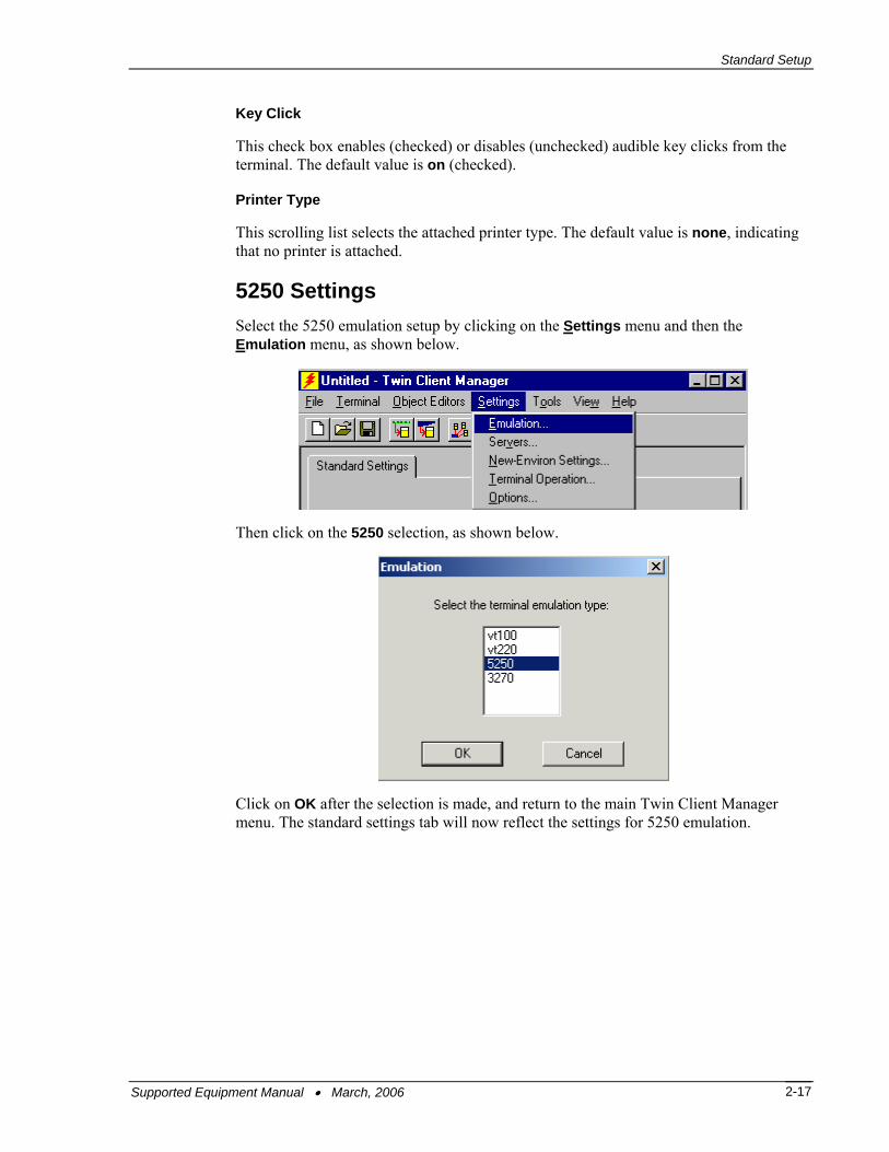
5250 Settings Select the 5250 emulation setup by clicking on the Settings menu and then the Emulation menu, as shown below.
Then click on the 5250 selection, as shown below.
Click on OK after the selection is made, and return to the main Twin Client Manager menu. The standard settings tab will now reflect the settings for 5250 emulation.
Supported Equipment Manual • March, 2006 2-17

Terminal Setup
Quadrant Mode
This scrolling list option defines the rules by which the terminal display is positioned in the larger host display. As defined by Twin Client, quadrants are fixed position "windows" in the host display, and the terminal display is located on whatever quadrant contains the current cursor position.
Off disables quadrant processing and Twin Client simply centers the current host input field in the terminal display.
On enables quadrant processing. However, input fields that cross quadrant boundaries result in a shift to the left in order to locate as much of the current input field on the terminal display.
Soft always positions on a quadrant boundary regardless of input field boundaries. Viewing keys are enabled.
Hard is the same as Soft except the viewing keys are disabled.
Lock locks the terminal display origin (upper left corner) to fixed row and column (x,y) coordinates in the host display. The coordinates are zero-based.
Font Size and Bold Font
Font size has a scrolling list of font size options. Bold Font has a check box that enables (checked) or disables (unchecked) the display of characters in bold font.
Key Click
This check box enables (checked) or disables (unchecked) audible key clicks from the terminal. The default value is on (checked).
Supported Equipment Manual • March, 2006 2-18

Standard Setup
Printer Type
This scrolling list selects the attached printer type. The default value is none, indicating that no printer is attached.
3270 Settings Select the 3270 emulation setup by clicking on the Settings menu and then the Emulation menu, as shown below.
Then click on the 3270 selection, as shown below.
Click on OK after the selection is made, and return to the main Twin Client Manager menu. The standard settings tab will now reflect the settings for 3270 emulation.
Supported Equipment Manual • March, 2006 2-19

Terminal Setup
Quadrant Mode
This scrolling list option defines the rules by which the terminal display is positioned in the larger host display. As defined by Twin Client, quadrants are fixed position "windows" in the host display, and the terminal display is located on whatever quadrant contains the current cursor position.
Off disables quadrant processing and Twin Client simply centers the current host input field in the terminal display.
On enables quadrant processing. However, input fields that cross quadrant boundaries result in a shift to the left in order to locate as much of the current input field on the terminal display.
Soft always positions on a quadrant boundary regardless of input field boundaries. Viewing keys are enabled.
Hard is the same as Soft except the viewing keys are disabled.
Lock locks the terminal display origin (upper left corner) to fixed row and column (x,y) coordinates in the host display. The coordinates are zero-based.
Font Size and Bold Font
Font size has a scrolling list of font size options. Bold Font has a check box that enables (checked) or disables (unchecked) the display of characters in bold font..
Key Click
This check box enables (checked) or disables (unchecked) audible key clicks from the terminal. The default value is on (checked).
Supported Equipment Manual • March, 2006 2-20

Standard Setup
Printer Type
This scrolling list selects the attached printer type. The default value is none, indicating that no printer is attached.
Importing Custom Configurations Existing installations that use a custom Symbol configuration file are easily converted to Twin Client with the Import option found under the File tab of Twin Client Manager.
Click on Import, and if necessary then click on the Browse button to locate the file.
To further simplify conversion, the import utility displays all conversion errors and warnings so that potential compatibility problems can be easily identified and corrected.
Supported Equipment Manual • March, 2006 2-21

Terminal Setup
Terminal Setup Using Twin Client Menus The Twin Client terminal software provides an internal menu system for configuring certain parameters on the terminal and for switching between Server and Telnet mode of operation. To access this menu system, press uppercase C at the startup screen as shown in the following figure.
Twin Client © 1991-2006, Connect, Inc. Keypress to continue Note: The date of 2006 is updated on the terminal at the time of a new release. The following menu appears in thick (Telnet) mode: Edit Server/Host IPs Edit License Key Switch Client Modes Run Client Emulator Exit to OS The following menu appears in thin (Server) mode: Edit Server/Host IPs Run Site Survey Switch Client Modes Run Client Emulator Exit to OS
Use the Up-Arrow and Down-Arrow keys to navigate the menu, and press Enter to select the highlighted option. Each menu option is described below.
Edit Server/Host IPs
If the host IP address(es) were not pre-configured as described in the Setting the Servers section of Configuring the Manager, or if you wish to change those settings using the terminal menus, select this option and enter up to four Host IP addresses as required.
Host 0 IP 206.183.67.155 Port 23__ <F3> Save <F7> Quit Press F3 to save the configurations.
Supported Equipment Manual • March, 2006 2-22

Standard Setup
Edit License Key
The client software can be authorized automatically, as described in the next section, Authorizing PowerNet. This menu option permits authorization of each terminal manually. Select this option to obtain the terminal's Identification Code, which is used to obtain the Authorization code from the Connect web site, as described in the next section.
The 12-digit value displayed at the top of the terminal screen is the Identification Code for the terminal.
00A0F826E614 Authorization ______________ not authorized <F3> Save <F7> Quit
Type the authorization code into the field as it appears on the web site. Punctuation characters, such as the hyphen (-), are required. Press F3 to save the authorization code.
Run Site Survey
This option (a feature of Spectrum 1) is applicable to Release 5.0 and may be obsolete for your terminal.
Switch Client Modes
The PowerNet Twin Client normally operates in Telnet mode, which provides direct connection to Telnet hosts. It can also operate in Server mode, through a PowerNet OpenAir server. Select this menu option to switch between Server and Telnet modes of operation. Note that the host socket address for the PowerNet OpenAir servers is 1800, which must also be changed in the Edit Server/Host IPs menu described above.
Run Client Emulator
After all desired changes have been made, select this option to return to the Twin Client main menu. Then press any key to establish the Telnet session and begin emulation. Refer to Starting a Telnet Session for further instructions.
Supported Equipment Manual • March, 2006 2-23

Terminal Setup
Authorizing PowerNet Each PowerNet Twin Client will run for 30 minutes at a time without authorization. Uninterrupted operation for a production environment is the result of authorizing the software.
The Twin Client Manager can automatically authorize the terminal over the wireless network if the following requirements are met: • A PC running Twin Client Manager is connected to the wire LAN segment with at
least one access point within range of the terminal. • The Airload Hex file is installed on the terminal. • The System ID of the PC on which Twin Client Manager is installed has been used to
obtain a site license Authorization code from the Connect web site.
To obtain the System ID of the Twin Client Manager, click on the Authorization option in the Tools menu, as shown below.
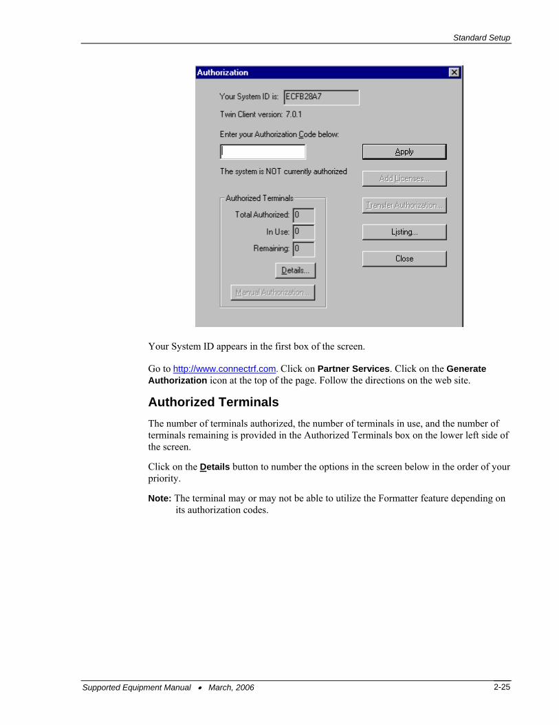
The Authorization window is displayed as shown below.
Supported Equipment Manual • March, 2006 2-24
Standard Setup
Your System ID appears in the first box of the screen.
Go to http://www.connectrf.com. Click on Partner Services. Click on the Generate Authorization icon at the top of the page. Follow the directions on the web site.
Authorized Terminals The number of terminals authorized, the number of terminals in use, and the number of terminals remaining is provided in the Authorized Terminals box on the lower left side of the screen.
Click on the Details button to number the options in the screen below in the order of your priority.
Note: The terminal may or may not be able to utilize the Formatter feature depending on its authorization codes.
Supported Equipment Manual • March, 2006 2-25

Terminal Setup
Click on an option and move it using the Up and Down buttons.
Click on OK when finished.
The Manual Authorization button is an alternate method of obtaining an authorization code for a terminal. This method does not utilize Airloader, as does the other method.
Click on this button, manually enter your mac address in the screen that appears, and click on OK. This enables you to generate individual authorization codes.
Add Licenses The Add Licenses feature is used when adding additional licenses to an already site licensed Twin Client Manager.
An example of this is the instance in which Twin Client Manager is licensed for 10 licenses, and the customer purchases another 10 licenses to make a total of 20 licenses.
From Twin Client Manager, choose Authorization from under the Tools menu.
Click on the Add Licenses button.
Supported Equipment Manual • March, 2006 2-26

Standard Setup
A pop-up box appears with the machine ID and a space for the additional license’s authorization code.
Enter the additional license’s authorization code and click on OK.
Use the machine ID in the pop-up box instead of the original machine ID to get your authorization code.
If adding users, click on the Add Licenses button before generating the authorization code to get the most current machine ID.
Supported Equipment Manual • March, 2006 2-27

Terminal Setup
Transfer Authorization The Transfer Authorization feature is used when moving a site license from one PC to another. After Twin Client Manager is installed on a new PC, you will need the system/machine ID for it. This ID appears in the first box of the authorization screen. From Twin Client Manager, select Authorization from under the Tools menu.
Click on the Transfer Authorization button on the old PC. You will be asked for the new system ID. Enter this new system ID. It will generate an authorization code for the new PC's Twin Client Manager.
Note: This feature only works if there are licenses remaining on the old PC.
Supported Equipment Manual • March, 2006 2-28

Standard Setup
Listing Click on the Listing button to view authorization codes issued.
The authorization codes used along with their corresponding serial numbers will appear.
Click on OK when finished. Click on the Close button when finished.
Supported Equipment Manual • March, 2006 2-29

Terminal Setup
Software Management In addition to providing functions for the download of files to the terminal via the traditional serial connection, the Twin Client Manager also provides for the management of terminal software and configurations automatically over the wireless network. This section describes the automated capability in detail.
Airloader Auto-Configuration The Airloader Auto-Configuration form is accessed from the Twin Client Manager Tools menu. Select Airloader.
Note: If no options are displayed, click on the Advanced<< button.
Enabling Automatic Downloads
Click to put a check in the box that allows terminals to be automatically configured via RF to enable automatic downloading. In the event that another PC on the network is already configured and active, the following warning message is displayed.
Supported Equipment Manual • March, 2006 2-30

Software Management
Synchronizing Configuration Files
Click to put a check in the Synchronize Configuration Files box to enable automatic synchronization of configuration files on the terminal. When the terminal is cold booted, its configuration files will be compared with the most recent on the PC. The terminal is updated automatically if it does not have the latest revision.
Synchronizing Program Files
Click to put a check in the Synchronize Program Files box to enable automatic synchronization of program files on the terminal. When the terminal is cold booted, its program files will be compared with the most recent on the PC. The terminal is updated automatically if it does not have the latest revision.
Automatic IP Address Assignment
An IP address does not need to be assigned to the terminal. The 8800 terminal can find the airloader server automatically.
Creating New Groups
New groups, with different configurations, can be created by clicking on Terminal/Group Manager, and then clicking the right mouse button as shown.
After the new group has been created, the group settings option becomes available for change, as shown below.
Supported Equipment Manual • March, 2006 2-31

Terminal Setup
After the Configuration File and all of the other parameters have been set, the group is made active by clicking in the Active check box.
Note: A setting under the Group allows you to associate a saved server file (.svr file) with a particular group. This means that the .svr file will be sent to the terminal in place of the default power.net file. The .svr files are created in Twin Client Manager under Tools/Servers.
Supported Equipment Manual • March, 2006 2-32

Software Management
Clicking on the Thin Mode button will cause all terminals in this group that are currently running in thick mode to be switched to thin mode the next time Airloader is run on the terminal. Click on the Schedule button to view a dialog box for scheduling an automatic Airloader update.
Select the desired time and click on OK. Click on Update Now to check all group members for updates.
Supported Equipment Manual • March, 2006 2-33

Terminal Setup
Setting the Segment
Checking the Segment button restricts a terminal group to a range of IP addresses. The IP Address can be any valid address on the segment as it is used only to identify the segment. The setting of the Net Mask can be used to restrict the range. This feature is useful for segregating terminal groups by location.
Setting Force Reload
Clicking on the Force Reload button forces all terminals within a group to be automatically updated. The following warning message appears.
Click on the Yes button to force the reload.
Setting the Default Terminal Group
New terminals that have not yet been assigned to any group are initially assigned to the default group in effect when they are cold-booted.
Any group can be made the default group by clicking on the group, and then clicking on the right mouse button. Then click on the Make Default option.
Reassigning Terminals
After a terminal has been configured and assigned to the default group, it can be reassigned to a new group by clicking on the terminal icon as shown below.
Supported Equipment Manual • March, 2006 2-34

Software Management
Then, holding the mouse button down, drag the terminal icon to the desired group as shown next.
Release the mouse button, which reassigns the terminal.
The next time the terminal is rebooted, it will be reconfigured as defined in the group specification.
Mobile Device Manager (MDM) Features Under Tools in Twin Client Manager are the Screen Watcher, Terminal Messenger, and RF Monitor features. Note: The terminal may or may not be able to utilize the Screen Watcher or Terminal
Messenger features depending on its authorization codes.
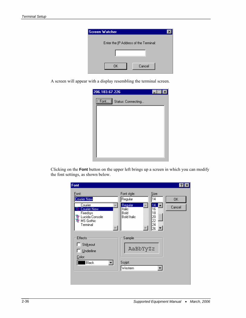
Select Screen Watcher, enter the terminal’s IP address, and click on OK.
Supported Equipment Manual • March, 2006 2-35
Terminal Setup
A screen will appear with a display resembling the terminal screen.
Clicking on the Font button on the upper left brings up a screen in which you can modify the font settings, as shown below.
Supported Equipment Manual • March, 2006 2-36

Software Management
Select Terminal Messenger from the Tools menu. You may enter an Address Range in the From and To boxes on this screen. Click on Add when finished. Enter a message to send in the space provided, select the terminal to receive this message by clicking on it in the Select Terminal(s) column, and click on the Send button to send the message of your choice to the terminal of your choice. See the example of the Terminal Messenger screen below.
To remove a terminal from the list of terminals receiving your message, click on the terminal number in the Select Terminal(s) column, and click on the Remove button. Click on the appropriate button, Remove All, Select All, or Unselect All, to remove all terminals, select all terminals, or unselect all terminals from the Select Terminal(s) list. Note: Use the Ctrl and Shift keys to select multiple terminals. Click on the Close button when finished.
Supported Equipment Manual • March, 2006 2-37
Terminal Setup
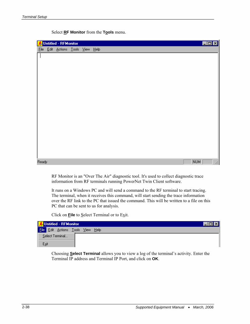
Select RF Monitor from the Tools menu.
RF Monitor is an "Over The Air" diagnostic tool. It's used to collect diagnostic trace information from RF terminals running PowerNet Twin Client software.
It runs on a Windows PC and will send a command to the RF terminal to start tracing. The terminal, when it receives this command, will start sending the trace information over the RF link to the PC that issued the command. This will be written to a file on this PC that can be sent to us for analysis.
Click on File to Select Terminal or to Exit.
Choosing Select Terminal allows you to view a log of the terminal’s activity. Enter the Terminal IP address and Terminal IP Port, and click on OK.
Supported Equipment Manual • March, 2006 2-38

Software Management
Click on Edit. Select Find, and/or Find Next to search for pieces of information in your log, or select Clear to clear the search.
Click on Actions to select Start Monitor or Stop Monitor.
Click on Tools to choose Set Debug Levels or Settings.
The options in Set Debug Levels are shown below.
Supported Equipment Manual • March, 2006 2-39

Terminal Setup
The maximum log file size can be set under Settings.
Click on View to show or hide the Toolbar and the Status Bar.
This is the Toolbar. It is found near the top of the screen.
This is the Status Bar. It is found at the bottom of the screen.
Click on About RF Monitor under Help to view version number information. Click on About Twin Client Manager under Help in the main menu to view the following screen.
Supported Equipment Manual • March, 2006 2-40

Software Management
RF Monitor is a very small program and does not even require installation. Just place it in a directory on your PC and create a shortcut to run it. It will run on all versions of Windows except V3.1 and Windows 95.
1. Move RF Monitor to a Windows PC with Network access to the RF terminal. 2. Run RF Monitor. (Create a shortcut or do a Start/Run.) 3. From the pull down menu, select File/Select Terminal. 4. Key in the RF terminal IP address and leave the port at 1802.
5. From the pull down menu, select Tools/Set Debug Levels. Set all levels to 9 except Datastream and SNA.
Supported Equipment Manual • March, 2006 2-41

Terminal Setup
6. With the RF terminal sitting at the Press Any Key prompt, select Actions/Start Monitor.
7. Press a key on the RF terminal to open a session, and you should see trace data in the RF Monitor window. When done, end the trace and the file will be named tnxxx.yyy.log (where xxx.yyy is the last 2 octets of the RF terminals IP address) in the directory in which RF Monitor was running.
Supported Equipment Manual • March, 2006 2-42

Software Management
Common Problems with RF Monitor
• The trace won’t start.
RF Monitor uses UDP to send commands to the RF device. On busy networks UDP packets are not always delivered. The terminal can miss the command to start the trace. Below are some things that can be useful. a. Ping the RF terminal from the PC used before starting RF Monitor. (This seems
to "open" a path to the terminal.)
b. Start the monitor with the terminal at the Press Any Key prompt. (While the terminal is at this prompt, it is not doing much and has a better chance of hearing the start trace command.)
• I don't understand what this trace means.
The trace that this tool collects is engineering level information. It allows an end user to collect information that can be analyzed by Connect engineering. It will generally be requested by Connect support to help diagnose a reported problem. To be able to read and understand these completely, you need to have an understanding of:
Supported Equipment Manual • March, 2006 2-43

Terminal Setup
a. Emulation protocols (IBM 5250, IBM 3270, DEC VT200, etc.) b. PowerNet Twin Client products c. RF Network concepts d. Wired network concepts e. Telnet sessions f. TCP/IP
They are text files that can be read with any editor or viewer and can be useful to end users and integrators even if they may not have all the requirements above.
• I have an intermittent problem and it could happen on any one of my 100 terminals. RF Monitor only does one terminal at a time. What can I do?
RF Monitor is not the right diagnostic tool for this type of problem. PowerNet products have another diagnostic tool that can be used called the "Diagnostic Server". This tool can be set up to run trace diagnostics on up to 300 terminals at the same time. This tool will be provided as needed for systems under PowerNet support agreement OR by T&M when they are not covered.
It also includes the service of a PowerNet support engineer.
Server Transfer is another feature. From the Tools menu, select Server Transfer.
The FTP Settings screen appears.
To send object editor and configuration files from Windows to your Linux box, enter your server address, and click on OK.
Supported Equipment Manual • March, 2006 2-44

Software Management
Sending Program and Configuration Files to the Terminal
1. Boot the terminal. 2. Go to Start, Settings, and Control Panel. 3. Double-click on the Communications icon. 4. Select the PC Connection tab. 5. Click on Change Connection if you want to change the baud rate. 6. Change the baud rate here if necessary, and click on OK. 7. On the PC, choose Connection Settings from the File menu in ActiveSync.
The Connection Settings screen appears as follows.
Supported Equipment Manual • March, 2006 2-45

Terminal Setup
8. Make sure that the box is checked in front of the option entitled Allow serial cable or infrared connection to this COM port.
9. Click on OK. While ActiveSync is connecting, you will see the following screen.
Supported Equipment Manual • March, 2006 2-46

Software Management
When ActiveSync has connected, you will see the screen below.
10. Select No, and then click Next. The Connected screen appears.
Supported Equipment Manual • March, 2006 2-47

Terminal Setup
11. On the PC, select Send Program Files to Terminal from the Terminal menu in Twin Client Manager.
The following screen will appear.
12. Click on OK.
The following screen will appear.
Supported Equipment Manual • March, 2006 2-48

Software Management
13. Click on OK.
14. On the PC, choose Send Configuration Files to Terminal from the Terminal menu
in Twin Client Manager.
You will see the following screen.
15. Click on OK.
The following screen will appear.
16. Click on OK. 17. On the terminal, click on Start, Programs, File Explorer, and Windows. 18. Select the Aironet Client Utility icon. 19. Enter the SSID, etc. 20. Click on OK. 21. Click on Start, Settings, and Control Panel. 22. Select the Network icon and choose on the Properties tab. 23. Set the IP Address, Subnet Mask, and Default Gateway, and click on OK. 24. Click on Start, Programs, Twin Client, and AirloaderSetup. 25. Make sure that the Run AirLoad checkbox is checked or unchecked, as desired. 26. Click on OK. 27. Warm boot the terminal.
Supported Equipment Manual • March, 2006 2-49

Terminal Setup
This page is intentionally blank.
Supported Equipment Manual • March, 2006 2-50

Chapter 3 • Keypad Configuration Table
16-key Diagram
func
alpha
keytop
space
F7 F8 F9 F10
p q r s t u v w x y x . ← F4 F5 tab
@ - _ : ? ! a b c d e f
enter
func alpha
x
7 8 9 0
4 5 6 ↓bksp → F1 F2 F3
g h i j k l m n o
1 2 3 ↑
Supported Equipment Manual • March, 2006 3-1

Keypad Configuration
16-key Table
Key VT 3270 5250 1 <1> <1> <1> 2 <2> <2> <2> 3 <3> <3> <3> 4 <4> <4> <4> 5 <5> <5> <5> 6 <6> <6> <6> 7 <7> <7> <7> 8 <8> <8> <8> 9 <9> <9> <9> 0 <0> <0> <0> F1 <Func><1> <Func><1> <Func><1> F2 <Func><2> <Func><2> <Func><2> F3 <Func><3> <Func><3> <Func><3> F4 <Func><4> <Func><4> <Func><4> F5 <Func><5> <Func><5> <Func><5> Tab <Func><6> <Func><6> <Func><6> F7 <Func><7> <Func><7> <Func><7> F8 <Func><8> <Func><8> <Func><8> F9 <Func><9> <Func><9> <Func><9> F10 <Func><0> <Func><0> <Func><0> a <Alpha><2> <Alpha><2> <Alpha><2> b <Alpha><2><2> <Alpha><2><2> <Alpha><2><2> c <Alpha><2><2><2> <Alpha><2><2><2> <Alpha><2><2><2> d <Alpha><3> <Alpha><3> <Alpha><3> e <Alpha><3><3> <Alpha><3><3> <Alpha><3><3> f <Alpha><3><3><<3> <Alpha><3>3<><3> <Alpha><3><3><3> g <Alpha><4> <Alpha><4> <Alpha><4> h <Alpha><4><4> <Alpha><4><4> <Alpha><4><4> i <Alpha><4>4<><4> <Alpha><4><4><4> <Alpha><4><4><4> j <Alpha><5> <Alpha><5> <Alpha><5> k <Alpha><5><5> <Alpha>5<><5> <Alpha><5><5> l <Alpha><5><5><5> <Alpha><5><5><5> <Alpha><5><5><5> m <Alpha><6> <Alpha><6> <Alpha><6> n <Alpha><6><6> <Alpha><6><6> <Alpha><6><6> o <Alpha><6><6><6> <Alpha><6><6><6> <Alpha><6><6><6> p <Alpha><7> <Alpha><7> <Alpha><7> q <Alpha><7><7> <Alpha><7><7> <Alpha><7><7> r <Alpha><7><7><7> <Alpha><7><7><7> <Alpha><7><7><7> s <Alpha><7><7><7><7> <Alpha><7><7><7><7> <Alpha><7><7><7><7> t <Alpha><8> <Alpha><8> <Alpha><8> u <Alpha><8><8> <Alpha><8><8> <Alpha><8><8> v <Alpha><8><8><8> <Alpha><8><8><8> <Alpha><8><8><8> w <Alpha><9> <Alpha><9> <Alpha><9> x <Alpha><9><9> <Alpha><9><9> <Alpha><9><9> y <Alpha><9><9><9> <Alpha><9><9><9> <Alpha><9><9><9> z <Alpha><9><9><9><9> <Alpha><9><9><9><9> <Alpha><9><9><9><9> A <Alpha><2><2><2><2> <Alpha><2><2><2><2> <Alpha><2><2><2><2> B <Alpha><2><2><2><2><2> <Alpha><2><2><2><2><2> <Alpha><2><2><2><2><2> C Alpha><2><2><2><2><2><2> Alpha><2><2><2><2><2><2> Alpha><2><2><2><2><2><2> D <Alpha><3><3><3><3> <3><3><3><3><3> <Alpha><3><3><3><3> E <Alpha><3><3><3><3><3> <Alpha><3><3><3><3><3> <Alpha><3><3><3><3><3> F Alpha><3><3><3><3><3><3> Alpha><3><3><3><3><3><3> Alpha><3><3><3><3><3><3> G <Alpha><4><4><4><4> <Alpha><4><4><4><4> <Alpha><4><4><4><4> H <Alpha><4><4><4><4><4> <Alpha><4><4><4><4><4> <Alpha><4><4><4><4><4> I Alpha><4><4><4><4><4><4> Alpha><4><4><4><4><4><4> Alpha><4><4><4><4><4><4> J <Alpha><5><5><5><5> <Alpha><5><5><5><5> <Alpha><5><5><5><5> K <Alpha><5><><5><5><5> <Alpha><5>5<><5><5><5> <Alpha><5><5><5><5><5> L Alpha><5><5><5><5><5><5> Alpha><5><5><5><5><5><5> Alpha><5><5><5><5><5><5> M <Alpha><6><6><6><6> <Alpha><6><6><6><6> <Alpha><6><6><6><6> N <Alpha><6><6><6><6><6> <Alpha><6><6><6><6><6> <Alpha><6><6><6><6><6>
Supported Equipment Manual • March, 2006 3-2

16-key Table
O Alpha><6><6><6><6><6><6> Alpha><6><6><6><6><6><6> Alpha><6><6><6><6><6><6> P <Alpha><7><7><7><7><7> <Alpha><7><7><7><7><7> <Alpha><7><7><7><7><7> Q Alpha><7><7><7><7><7><7> Alpha><7><7><7><7><7><7> Alpha><7><7><7><7><7><7> R Alpha><7><7><7><7><7><7><7 Alpha><7><7><7><7><7><7><7 Alpha><7><7><7><7><7><7><7 S Alpha><7><7><7><7><7><7><7><7 Alpha><7><7><7><7><7><7><7><7 Alpha><7><7><7><7><7><7><7><7 T <Alpha><8><8><8><8> <Alpha><8><8><8><8> <Alpha><8><8><8><8> U <Alpha><8><8><8><8><8> <Alpha><8><8><8><8><8> <Alpha><8><8><8><8><8> V Alpha><8><8><8><8><8><8> Alpha><8><8><8><8><8><8> Alpha><8><8><8><8><8><8> W <Alpha><9><9><9><9><9> <Alpha><9><9><9><9><9> <Alpha><9><9><9><9><9> X Alpha><9><9><9><9><9><9> Alpha><9><9><9><9><9><9> Alpha><9><9><9><9><9><9> Y Alpha><9><9><9><9><9><9><9 Alpha><9><9><9><9><9><9><9 Alpha><9><9><9><9><9><9><9 Z Alpha><9><9><9><9><9><9><9><9 Alpha><9><9><9><9><9><9><9><9 Alpha><9><9><9><9><9><9><9><9 ↑ <↑> <↑> <↑> ← <Func><↓> <Func><↓> <Func><↓> ↓ <↓> <↓> <↓> → <Func><↑> <Func><↑> <Func><↑> @ at sign <Alpha><1> <Alpha><1> <Alpha><1> - hyphen <Alpha><1><1> <Alpha><1><1> <Alpha><1><1> _ underscore <Alpha><1><1><1> <Alpha><1><1><1> <Alpha><1><1><1> : colon <Alpha><1><1><1><1> <Alpha><1><1><1><1> <Alpha><1><1><1><1> ? question <Alpha><1><1><1><1><1> <Alpha><1><1><1><1><1> <Alpha><1><1><1><1><1> ! exclamation Alpha><1><1><1><1><1><1> Alpha><1><1><1><1><1><1> Alpha><1><1><1><1><1><1> . period <Alpha><0> <Alpha><0> <Alpha><0> Enter <Enter> <Enter> <Enter> Space <Alpha><↑> <Alpha><↑> <Alpha><↑> Bksp <Alpha><↓> <Alpha><↓> <Alpha><↓>
Supported Equipment Manual • March, 2006 3-3

Keypad Configuration
9-key Diagram There is no special key mapping for the 9-key terminal. The user can remap the touch keyboard in a similar fashion to the 2840. See the 2840 documentation at: http://www.connectrf.com/ster.htm
9-key Table There is no special key mapping for the 9-key terminal. The user can remap the touch keyboard in a similar fashion to the 2840. See the 2840 documentation at: http://www.connectrf.com/ster.htm
Supported Equipment Manual • March, 2006 3-4

Chapter 4 • Error Message Resolution Guide
Twin Client Error Message Resolution Guide
Message Reason Solution Reference Tech Note
ENTRY TOO LONG; Trying to key beyond the field size. Ensure that you are entering input into the correct field.
---
ALPHABETIC ONLY; Trying to key a character that is not alphabetic.
Ensure that you are entering input into the correct field.
---
MINUS NOT VALID; Trying to key a Minus sign. Ensure that you are entering input into the correct field.
---
DECIMAL NOT VALID; Trying to key a Decimal (period). Ensure that you are entering input into the correct field.
---
ALPHANUMERIC ONLY; Trying to key characters other than Alphabetic and numeric.
Ensure that you are entering input into the correct field.
---
NUMERIC ONLY; Trying to key characters other than numeric. Ensure that you are entering input into the correct field.
---
ENTRY TOO SHORT; Trying to exit the field before it is filled. Ensure that you are entering input into the correct field.
---
Supported Equipment Manual • March, 2006 4-1

Error Message Resolution Guide
Message Reason Solution Reference Tech Note INVALID KEY; The key pressed is not valid. Ensure that you are entering input into the
correct field. ---
MUST CLEAR FIELD; Trying to enter data in a field that must be cleared first.
Ensure that you are entering input into the correct field.
---
SCAN NOT ALLOWED; Trying to scan into a key only field. Ensure that you are entering input into the correct field.
---
KEY NOT ALLOWED; Trying to key into a scan only field. Ensure that you are entering input into the correct field.
---
ENTRY TOO SHORT; Trying to exit the field before it is filled. Ensure that you are entering input into the correct field.
---
RECOVERABLE ERROR; Encountered an error from which you can continue.
Verify that your configuration settings for the hardware being used, usually a printer and cable issue.
---
UNRECOVERABLE ERROR;
Encountered an error from which you can NOT continue.
Verify that your Network settings are correct and you are in the correct mode using the correct Port.
T1113, T1114, T1161, T1171, T1187 and T1194
FUNCTION: \n\nFILE: \nLINE: \nCODE;
Encountered an error from which you can NOT continue.
Notify Connect over the WEB incident reporting system.
---
Press any key\nFor More Details...;
Press Enter for more information. Advisory message. ---
Press any key; Press a key to continue. Advisory message. ---
Connection ERROR.\nREBOOT MOBILE UNIT;
Could not Connect. Verify that your Network settings are correct and you are in the correct mode using the correct Port.
T1113, T1114, T1161, T1171, T1187 and T1194
Supported Equipment Manual • March, 2006 4-2

Error Message Resolution Guide
Message Reason Solution Reference Tech Note
Disconnect ERROR.\nREBOOT MOBILE UNIT;
Could Not Disconnect. Verify that your Network settings are correct and you are in the correct mode using the correct Port.
T1113, T1114, T1161, T1171, T1187 and T1194
RF Send ERROR.\nREBOOT MOBILE UNIT;
Could not send. Most likely a range, access point, radio, host or network issue. Troubleshoot the customer’s environment.
T1113, T1114, T1161, T1171, T1187 and T1194
RF Receive ERROR.\nREBOOT MOBILE UNIT;
Could not Receive. Most likely a range, access point, radio, host or network issue. Troubleshoot the customer’s environment.
T1113, T1114, T1161, T1171, T1187 and T1194
RF Check ERROR.\nREBOOT MOBILE UNIT;
Could not run the RF Survey. Most likely a range, access point, radio, host or network issue. Troubleshoot the customer’s environment.
T1113, T1114, T1161, T1171, T1187 and T1194
RF Timeout ERROR.\nREBOOT MOBILE UNIT;
Have been trying to contact the host for the radio timeout period (2 minutes default).
Most likely a range, access point, radio, host or network issue. Troubleshoot the customer’s environment.
T1113, T1114, T1161, T1171, T1187 and T1194
REBOOT MOBILE UNIT; Reboot the Mobile Unit do to loss of connection.
Most likely a range, access point, radio, host or network issue. Troubleshoot the customer’s environment.
T1113, T1114, T1161, T1171, T1187 and T1194
Retry (Y/N)?; Try again. Try to send or receive again, or perhaps ensure that the printer is cabled to the Mobile Unit and is on.
---
TIMEOUT\n\nSending Data; Mobile Unit out of the coverage area. Most likely a range, access point, radio, host or network issue. Troubleshoot the customer’s environment.
T1113, T1114, T1161, T1171, T1187 and T1194
Supported Equipment Manual • March, 2006 4-3

Error Message Resolution Guide
Message Reason Solution Reference Tech Note
TIMEOUT\n\nReceiving Data;
Mobile Unit out of the coverage area. Most likely a range, access point, radio, host or network issue. Troubleshoot the customer’s environment.
T1113, T1114, T1161, T1171, T1187 and T1194
Host Received Data\nAwaiting App Reply!;
Mobile Unit has sent and received an acknowledgement from the IP stack and is waiting for the application to return data.
Most likely a host or network issue. Troubleshoot the customer’s environment. Probable causes are Database record locking, application program failure, Host failure or network failure.
T1113, T1114, T1161, T1171, T1187 and T1194
* WAITING TO SEND *; Mobile Unit out of the coverage area. Most likely a range, access point, radio, host or network issue. Troubleshoot the customer’s environment.
T1113, T1114, T1161, T1171, T1187 and T1194
TCP Error Reading\nMAC Address.\nREBOOT MOBILE UNIT;
Could not obtain the Mac Address from the Mobile Unit.
Possible hardware, driver or stack problem Contact the Mobile Unit manufacturer.
---
Invalid TIP Command; Bad internal protocol. Notify Connect over the WEB incident reporting system.
---
Session Ended\nBy User or Host;
User, Host, application or network has ended the session.
If the user did not end the session, most likely host or network issues. Troubleshoot the customer’s environment.
T1113, T1114, T1161, T1171, T1187 and T1194
Server Packet Error; Bad Protocol detected. Usually a result of bad cabling, power or faulty transceiver. Also, will receive this if the Mobile Unit is in the wrong mode for server operation.
---
Supported Equipment Manual • March, 2006 4-4

Error Message Resolution Guide
Message Reason Solution Reference Tech Note Error receiving host\nlist from Server;
Bad Protocol detected. Usually a result of bad cabling, power or faulty transceiver. Also, will receive this if the Mobile Unit is in the wrong mode for server operation.
---
Unexpected Server\ndata received;
Bad Protocol detected. Usually a result of bad cabling, power or faulty transceiver. Also, will receive this if the Mobile Unit is in the wrong mode for server operation.
---
Error starting\nhost application;
Connected to the server but can not connect to the distant end.
Configure the server handler to access the host application.
---
Select Host or App; Need to choose your Host/application destination.
User selection required. ---
Connecting...; Attempting to connect to the Host/application. Advisory message. ---
TCP Error\nReading IP Address\nREBOOT MOBILE UNIT;
Mobile Unit missing Network IP information. Configure the Mobile Unit with the correct network IP information.
---
Printer start error; Could not initialize the printer. Cable or power issue with the printer. ---
Battery too low\nto print; Not enough power to print. Replace the battery with a fully recharged battery.
---
Paper Feed Error\nFix Then Hit Enter;
Paper in the printer is not ready. Replace the paper or rethread the paper in the printer.
---
Printer Error\nPrint Ended; Can not print. Check cable, battery, communication settings and paper in the printer.
---
Supported Equipment Manual • March, 2006 4-5

Error Message Resolution Guide
Message Reason Solution Reference Tech Note User Count Exceeded.\n Session Ended;
Possible authorization issue. Verify that you have the correct number of licenses for the number of Mobile Units you are using.
---
Primary Unavailable\nTrying Alternate;
First Host IP address not available trying the remaining addresses in the Host list.
Verify the host address. ---
APMAC.DAT Error\nSession Ended;
Access point Media Access Control error. Most likely a range, access point, radio, host or network issue. Troubleshoot the customer’s environment.
T1113, T1114, T1161, T1171, T1187 and T1194
MUIP.DAT Error\nSession Ended;
Mobile Unit IP Error. Most likely a Mobile Unit network setting issue. Troubleshoot the customer’s environment.
T1113, T1114, T1161, T1171, T1187 and T1194
Missing Subnet IP\nSession Ended;
Mobile Unit IP Netmask Error. Most likely a Mobile Unit network setting issue. Troubleshoot the customer’s environment.
T1113, T1114, T1161, T1171, T1187 and T1194
Error Opening File; File is missing. Verify that the configuration files are on the Mobile Unit. Or perhaps there is a hardware failure.
---
Telnet API\nnot found; Program files are missing. Reload program files. ---
Battery Low Warning\n\nReplace Battery Soon;
Not enough power to operate the Mobile Unit. Replace the battery with a fully recharged battery.
---
No Host List.\nPress any key\nTo Edit Host IP's;
Have not configured your target hosts. Configure the target host IP addresses. ---
Unable to Allocate\nFont Memory;
Mobile Unit does not have enough memory to load the fonts.
Reduce the fonts in use or expand the memory in the Mobile Unit.
---
Font Loading Error; Could not load the font. Ensure that the font is available to load.
---
Supported Equipment Manual • March, 2006 4-6

Error Message Resolution Guide
Message Reason Solution Reference Tech Note Printer Not Ready\nPress R to Retry\nC to Cancel Print;
Can not print. Check cable, battery, communication settings and paper in the printer.
---
Mobile Unit in\nDemonstration Mode\nfor TwinClient;
Running in demo mode. Purchase a license from Connect. ---
Connected to Host; Successful connection to the target Host. Advisory message.
---
Telnet Mode not\nsupported on\nthis Mobile Unit;
This Mobile Unit must be used with a Connect Server.
Order a Connect Server.
---
Telnet Setup files\nnot found. Reload\nfiles then switch;
Customer specific configuration files are missing.
Load the configuration files into the Mobile Unit from Twin Client Manager.
---
Switched Client to\nTelnet Direct Mode;
Mobile Unit running in Telnet mode direct to the target Host.
Advisory message.
---
Switched Client to\nServer Based Mode;
Mobile Unit running through a Connect server in Server mode usually at port 1800.
Advisory message. ---
Port 23 is only\nallowed in Telnet Mode;
Can not set the port to 23 in Server mode. Port 23 is the standard Telnet port.
Advisory message. ---
Not Enough Memory\nTo Run;
Mobile Unit does not have the capacity to run the program do to memory restrictions.
Expand the Mobile Unit memory. ---
Press any key; Press a key to continue. Advisory message. ---
TwinClient Telnet; Prompt. Advisory message.
---
Supported Equipment Manual • March, 2006 4-7

Error Message Resolution Guide
Message Reason Solution Reference Tech Note TwinClient Server; Prompt. Advisory message. ---
TwinClient TN3270; Prompt. Advisory message. ---
TwinClient TN5250; Prompt. Advisory message. ---
TwinClient TNVT; Prompt. Advisory message. ---
(c)1991-2006 Connect; Prompt. Advisory message. ---
Edit Menu Options; Menu Title. Advisory message. ---
Edit Mobile Unit IP; Menu Option. Advisory message. ---
Edit Server/Host IPs; Menu Option. Advisory message. ---
Edit Radio Option; Menu Option. Advisory message. ---
Edit License Key; Menu Option. Advisory message. ---
Run Site Survey; Menu Option. Advisory message. ---
Supported Equipment Manual • March, 2006 4-8

Error Message Resolution Guide
Message Reason Solution Reference Tech Note Switch Client Modes; Menu Option. Advisory message. ---
Run TwinClient; Menu Option. Advisory message. ---
Exit to OS; Menu Option. Advisory message. ---
Printer may not be\nplugged in or\nturned on!;
Can not print. Check cable, battery, communication settings and paper in the printer.
---
OUT OF RANGE OF BASE; Mobile Unit out of the coverage area. Most likely a range, access point, radio, host or network issue. Troubleshoot the customer’s environment.
T1113, T1114, T1161, T1171, T1187 and T1194
CONNECT SERIAL CABLE; Serial cable not connected to the Mobile Unit. Check cable, battery and communication settings for the Mobile Unit.
---
REMOVE SERIAL CABLE; Remove serial cable from to the Mobile Unit. Check cable, battery and communication settings for the Mobile Unit.
---
PLACE IN CRADLE; Place the Mobile Unit in the cradle. Advisory message. ---
REMOVE FROM CRADLE; Remove Mobile Unit from the cradle. Advisory message. ---
ACQUIRING CRADLE BUS; Attempting to access the cradle through the serial port you have configured.
Advisory message. ---
Supported Equipment Manual • March, 2006 4-9

Error Message Resolution Guide
Message Reason Solution Reference Tech Note
Printer Out\nOf Range; Printer out of the coverage area. Most likely a range, access point or radio issue. Troubleshoot the customer’s environment.
T1113, T1114, T1161, T1171, T1187 and T1194
Connection Refused\nBy Host;
You connected to the target host but the host disconnected you.
Verify that the configuration file has the correct Mobile Unit type and New environment variable set. Fallback to the Connect Default to verify the connection.
---
Connection Timed Out; You connected to the host but did not logon in the appropriate time so the host disconnected you.
Modify the Host parameters for login. ---
Connection Failed\nHost Not Responding;
Could not connect to the Host. Most likely a range, access point, radio, host or network issue. Troubleshoot the customer’s environment.
T1113, T1114, T1161, T1171, T1187 and T1194
Connection Failed\nHost Unreachable;
Could not connect to the Host. Most likely a range, access point, radio, host or network issue. Troubleshoot the customer’s environment.
T1113, T1114, T1161, T1171, T1187 and T1194
Mobile Unit Out\nOf Range, Unable\nTo Transmit;
Mobile Unit out of the coverage area. Most likely a range, access point, radio, host or network issue. Troubleshoot the customer’s environment.
T1113, T1114, T1161, T1171, T1187 and T1194
Mobile Unit Out\nOf Range, Unable\nTo Receive;
Mobile Unit out of the coverage area. Most likely a range, access point, radio, host or network issue. Troubleshoot the customer’s environment.
---
Printer Not\nResponding; Can not print. Check cable, battery, communication settings and paper in the printer.
---
Printer Out\nOf Range; Printer out of the coverage area. Most likely a range, access point or radio issue. Troubleshoot the customer’s environment.
T1113, T1114, T1161, T1171, T1187 and T1194
Supported Equipment Manual • March, 2006 4-10

Error Message Resolution Guide
Message Reason Solution Reference Tech Note Print Complete; Prompt. Advisory message. ---
Reprint (Y/N)?; Yes or No prompt for a reprint. Advisory message. ---
WARNING; Prompt. Advisory message. ---
Turning power off\nduring a session\nwill cause the\nprogram to restart;
This Mobile Unit will disconnect the session if powered off.
Mobile Unit manufacturer limitation. Advisory message.
---
Are you sure (y/n)?; Yes or No prompt for a confirmation. Advisory message. ---
You Sure? (YyNn); Yes or No prompt for a confirmation. Advisory message. ---
Domain Name Server\nNot Set;
DOMAIN NAME SERVER not configured. Configure the Mobile Unit with the correct network IP information.
---
Domain Name Server\nQuery Memory Error;
Memory error on the Mobile Unit Expand the Mobile Unit memory or return the Mobile Unit for repair.
---
Domain Name Server\nQuery Sending Error;
Mobile Unit out of the coverage area. Most likely a range, access point, radio, host or network issue. Troubleshoot the customer’s environment.
T1113, T1114, T1161, T1171, T1187 and T1194
Supported Equipment Manual • March, 2006 4-11

Error Message Resolution Guide
Message Reason Solution Reference Tech Note
Domain Name Server\nQuery Receive Error;
Mobile Unit out of the coverage area. Most likely a range, access point, radio, host or network issue. Troubleshoot the customer’s environment.
T1113, T1114, T1161, T1171, T1187 and T1194
Domain Name Server\nUnavailable;
Could not connect to the DOMAIN NAME SERVER.
Most likely a range, access point, radio, host or network issue. Troubleshoot the customer’s environment.
T1113, T1114, T1161, T1171, T1187 and T1194
Error loading\nparameter file;
Could not load the parameter file. Reload the correct configuration files. ---
Could not open\ntelnet interface;
Could not Telnet. Reload the program files. ---
Could not set\mtelnet options;
Could not use the Telnet configuration. Reload the correct configuration files. ---
Setup file\nsetting mismatch\nReload Setup;
Emulation program selected is not compatible with the configuration file on the Mobile Unit.
Remove the emulation and configuration files. Run clear Telnet on the Mobile Unit then reload the Mobile Unit with the proper emulation and configuration files.
---
Display formatting\ntoo large for\ncurrent screen;
Mobile Unit does not have enough memory to run your configured reformatted screens.
Expand the Mobile Unit memory or order a server from Connect.
---
Mobile Unit\ninitialization error;
Mobile Unit problem. Return the Mobile Unit to the manufacturer for repair.
---
Host/App/Network\nclosed the session;
Customer’s environment disconnected the Mobile Unit session.
Most likely a range, access point, radio, host or network issue. Troubleshoot the customer’s environment.
T1113, T1114, T1161, T1171, T1187 and T1194
Supported Equipment Manual • March, 2006 4-12

Error Message Resolution Guide
Message Reason Solution Reference Tech Note
Disconnecting...; Prompt. Advisory message. ---
Scan Barcode; Bar code scanning test. Advisory message. ---
Enter Setup\nPassword; Prompt. Advisory message. ---
Enter Profile \nPassword; Prompt. Advisory message. ---
Host IP; Host IP address prompt. Enter target host IP address. ---
Host Name; Host name prompt. Enter target host Name. ---
Port; Host IP port required. Enter 23 for Telnet or 1800 for a Connect server. Could also be a different number depending on the customer’s environment.
T1113, T1114, T1161, T1171, T1187 and T1194
Mobile Unit Type; Prompt. Advisory message. ---
WARNING: This will \nend any\ncurrent session;
Prompt. Advisory message. ---
Continue (Y/N)?; Prompt. Advisory message.
---
Supported Equipment Manual • March, 2006 4-13

Error Message Resolution Guide
Message Reason Solution Reference Tech Note HOST ENTRY; Prompt. Advisory message. ---
VT(100/220) Setup; Prompt. Advisory message. ---
Mobile Unit Info; Prompt. Advisory message. ---
Emulation Setup; Prompt. Advisory message. ---
ANSI Setup; Prompt. Advisory message. ---
Miscellaneous Setup; Prompt. Advisory message. ---
Mobile Unit Type; Prompt. Advisory message. ---
Control Codes; Prompt. Advisory message. ---
Local Echo; Prompt. Advisory message. ---
<BK SP> Sends; Prompt. Advisory message. ---
New Line Mode; Prompt. Advisory message. ---
Supported Equipment Manual • March, 2006 4-14
Error Message Resolution Guide
Message Reason Solution Reference Tech Note
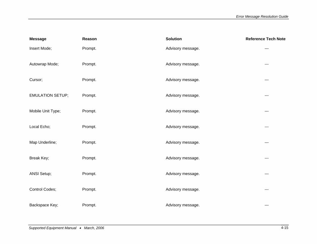
Insert Mode; Prompt. Advisory message. ---
Autowrap Mode; Prompt. Advisory message. ---
Cursor; Prompt. Advisory message. ---
EMULATION SETUP; Prompt. Advisory message. ---
Mobile Unit Type; Prompt. Advisory message. ---
Local Echo; Prompt. Advisory message. ---
Map Underline; Prompt. Advisory message. ---
Break Key; Prompt. Advisory message. ---
ANSI Setup; Prompt. Advisory message. ---
Control Codes; Prompt. Advisory message. ---
Backspace Key; Prompt. Advisory message. ---
Supported Equipment Manual • March, 2006 4-15

Error Message Resolution Guide
Message Reason Solution Reference Tech Note
MISCELLANEOUS SETUP; Prompt. Advisory message. ---
Test Options; Prompt. Advisory message. ---
Login Options; Prompt. Advisory message. ---
TEST OPTIONS; Prompt. Advisory message. ---
Printer Test; Prompt. Advisory message. ---
Scan Code Test; Prompt. Advisory message. ---
LOGIN OPTIONS; Prompt. Advisory message. ---
User Name; Prompt. Advisory message. ---
User Password; Prompt. Advisory message. ---
ON; Prompt. Advisory message. ---
OFF; Prompt. Advisory message. ---
Supported Equipment Manual • March, 2006 4-16
Error Message Resolution Guide
Message Reason Solution Reference Tech Note
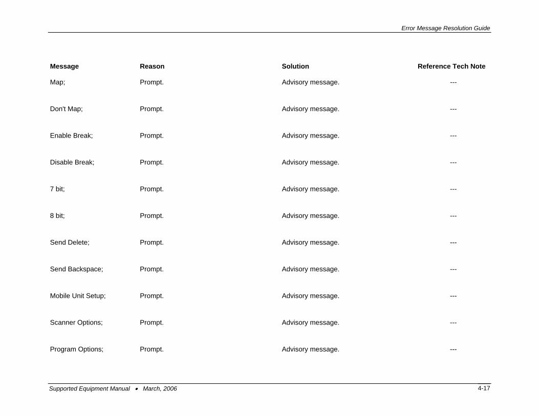
Map; Prompt. Advisory message. ---
Don't Map; Prompt. Advisory message. ---
Enable Break; Prompt. Advisory message. ---
Disable Break; Prompt. Advisory message. ---
7 bit; Prompt. Advisory message. ---
8 bit; Prompt. Advisory message. ---
Send Delete; Prompt. Advisory message. ---
Send Backspace; Prompt. Advisory message. ---
Mobile Unit Setup; Prompt. Advisory message. ---
Scanner Options; Prompt. Advisory message. ---
Program Options; Prompt. Advisory message. ---
Supported Equipment Manual • March, 2006 4-17

Error Message Resolution Guide
Message Reason Solution Reference Tech Note
Special Options; Prompt. Advisory message. ---
Beeper Options; Prompt. Advisory message. ---
Exit to DOS; Prompt. Advisory message. ---
Backlight Time; Prompt. Advisory message. ---
Enter Key Action; Prompt. Advisory message. ---
Reset Options; Prompt. Advisory message. ---
Font Size; Prompt. Advisory message. ---
Portable Printer; Prompt. Advisory message. ---
Reprint Option; Prompt. Advisory message. ---
Data IDs; Prompt. Advisory message. ---
Internal/External; Prompt. Advisory message. ---
Supported Equipment Manual • March, 2006 4-18

Error Message Resolution Guide
Message Reason Solution Reference Tech Note
Modify Beeps; Prompt. Advisory message. ---
Message Beeps; Prompt. Advisory message. ---
Scan Identifier; Prompt. Advisory message. ---
AID Scan Setup; Prompt. Advisory message. ---
Long Scans; Prompt. Advisory message. ---
Scan Send; Prompt. Advisory message. ---
Yes; Prompt. Advisory message. ---
No; Prompt. Advisory message. ---
Normal; Prompt. Advisory message. ---
Double Wide; Prompt. Advisory message. ---
Double High; Prompt. Advisory message. ---
Supported Equipment Manual • March, 2006 4-19

Error Message Resolution Guide
Message Reason Solution Reference Tech Note
Double High and Wide; Prompt. Advisory message. ---
Errors Only; Prompt. Advisory message. ---
Automatic; Prompt. Advisory message. ---
All Messages; Prompt. Advisory message. ---
Reject; Prompt. Advisory message. ---
Truncate; Prompt. Advisory message. ---
Split; Prompt. Advisory message. ---
Do Not Send; Prompt. Advisory message. ---
Always Send; Prompt. Advisory message. ---
Last Field Only; Prompt. Advisory message. ---
Internal; Prompt. Advisory message. ---
Supported Equipment Manual • March, 2006 4-20

Error Message Resolution Guide
Message Reason Solution Reference Tech Note
External; Prompt. Advisory message. ---
none; Prompt. Advisory message. ---
monarch; Prompt. Advisory message. ---
pddumb; Prompt. Advisory message. ---
comtec; Prompt. Advisory message. ---
rascal; Prompt. Advisory message. ---
codewriter; Prompt. Advisory message. ---
comtec(S); Prompt. Advisory message. ---
User Name; Prompt. Advisory message. ---
Password; Prompt. Advisory message. ---
Frequency: Hz; Prompt. Advisory message. ---
Supported Equipment Manual • March, 2006 4-21

Error Message Resolution Guide
Message Reason Solution Reference Tech Note
Duration: ms; Prompt. Advisory message. ---
Delay: ms; Prompt. Advisory message. ---
Select Scanner; Prompt. Advisory message. ---
Setup Scanner; Prompt. Advisory message. ---
Scan Test; Prompt. Advisory message. ---
Scan Operation; Prompt. Advisory message. ---
Laser; Prompt. Advisory message. ---
Contact/Pulse; Prompt. Advisory message. ---
Contact/No Pulse; Prompt. Advisory message. ---
Auto/Pulse; Prompt. Advisory message. ---
Auto/No Pulse; Prompt. Advisory message. ---
Supported Equipment Manual • March, 2006 4-22

Error Message Resolution Guide
Message Reason Solution Reference Tech Note
Wand Simulation; Prompt. Advisory message. ---
VT100; Prompt. Advisory message. ---
VT220; Prompt. Advisory message. ---
SETUP; Prompt. Advisory message. ---
Mobile Unit IP/Radio; Prompt. Advisory message. ---
Host List; Prompt. Advisory message. ---
NULL; Prompt. Advisory message. ---
Supported Equipment Manual • March, 2006 4-23