Support Pack - Armstrong Medical€¦ · Support Pack Content p4 ... 3d 3c 3e 4 5 6 8 7 9 3f...
12
Support Pack
Transcript of Support Pack - Armstrong Medical€¦ · Support Pack Content p4 ... 3d 3c 3e 4 5 6 8 7 9 3f...

Support Pack


3
Support Pack
Content
p4High Flow Oxygen Therapy, Instructions for use p4
AquaNASE, Fitting guide p5
CPAP, Instructions for use p6
BPAP, Instructions for use p7
V2TM Face Mask, Fitting guide p8
MAXBlendTM, Oxygen sensor calibration procedure p10
AquaVENT® Heater setup p11
Support Pack

4
o37 C
21%
High Flow
1. Select correct size of AquaNASE prongs
2. Apply AquaNASE and secure neck strap
as shown
3. Insert humidification chamber onto heater
plate and spike water bag
4. Attach circuit as shown a-d
5. Connect heater cable and temperature probes
6. Turn on heater and select NIV mode
7. Set flow at 15l/min and select prescribed
FiO2 for 2 minutes
8. Increase flow to 30l/min and monitor PaO2,
SpO2 and respiratory rate
Instructions for use
1
4a
2
4b4c
4d
3
5
6
7
8
Oxygen Therapy

5
High Flow
Fit the looped neck support
strap by placing over patients
head and sliding down around
the neck as shown.
Step 1
AquaNASE®Fitting guide
Adjust the looped neck support
strap by pulling one strap
through the clamp as shown.
Step 2
Place the elasticated strap
around the patients head.
Step 3
Adjust the ends of the
elasticated strap to secure the
device.
Step 4
6
5
20
21%
o37 C
CPAP
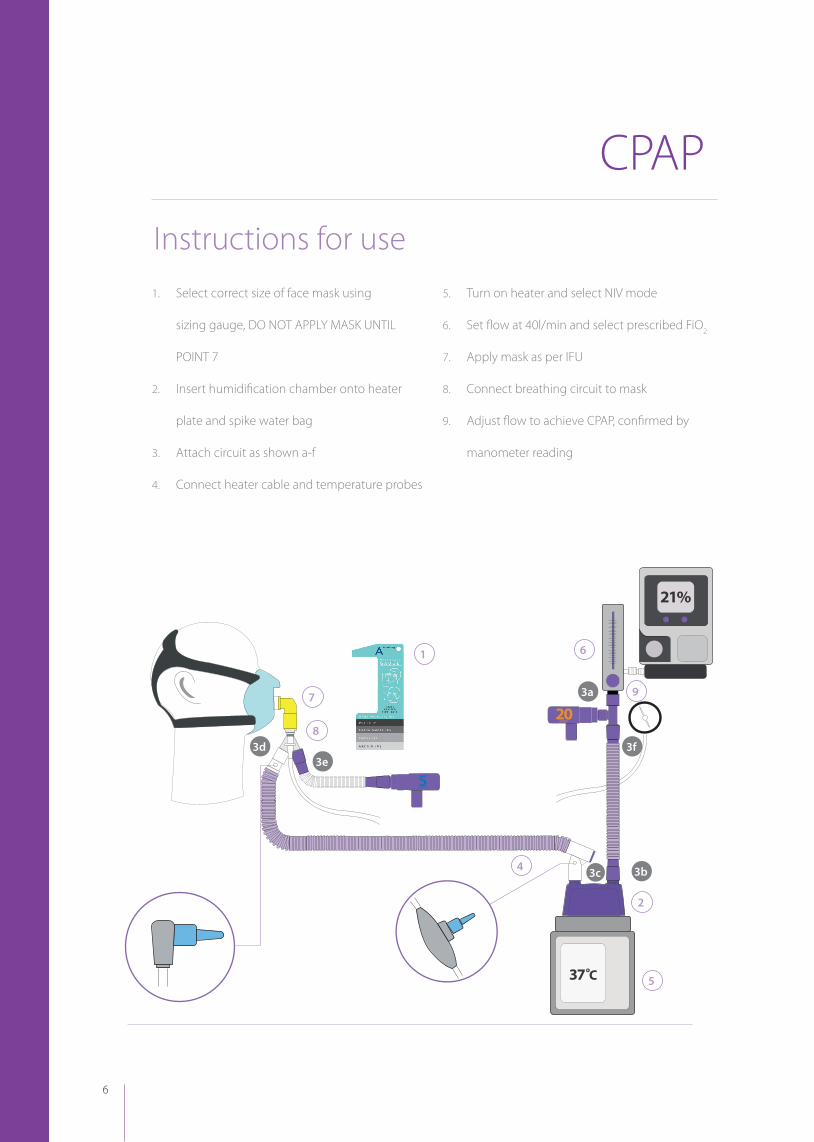
1. Select correct size of face mask using
sizing gauge, DO NOT APPLY MASK UNTIL
POINT 7
2. Insert humidification chamber onto heater
plate and spike water bag
3. Attach circuit as shown a-f
4. Connect heater cable and temperature probes
5. Turn on heater and select NIV mode
6. Set flow at 40l/min and select prescribed FiO2
7. Apply mask as per IFU
8. Connect breathing circuit to mask
9. Adjust flow to achieve CPAP, confirmed by
manometer reading
1
2
3a
3b
3d
3c
3e
4
5
6
8
7 9
3f
Instructions for use

7
Instructions for use
o37 C
BPAP
1. Select correct size of face mask using sizing
gauge, DO NOT APPLY MASK UNTIL POINT 8
2. Insert humidification chamber onto heater
plate and spike water bag
3. Attach circuit as shown a-d
4. Connect heater cable and temperature probes
5. Turn on heater and select NIV mode
6. Select mode of ventilation as prescribed
7. Apply mask as per IFU
8. Connect breathing circuit to mask, ensure CO2
1
2
3a
3b
3d
7
4
5
8
6
3c

8
Use sizing gauge to select
appropriate size of mask. Place
gauge tip to the bridge of
patient’s nose. Align chin to
scale to indicate correct size for
patient. If in between 2 sizes,
use smaller size for a better fit.
Step 1
Remove mask from packaging
and release the bottom two
quick release strap clips. Label
should be facing outwards and
readable.
Step 2
Place patient’s chin in chin
cup and gently roll mask up to
cover mouth and create a seal
over the bridge of the nose.
Step 3
Slide headgear over patient’s
head and reconnect bottom
strap clips.
Step 4
V2TM Face Mask Fitting guide

9
Adjust top and bottom velcro
straps by pulling slightly to
hold the mask in place. Adjust
the straps at the crown of
the head to create a secure,
comfortable fit.
Step 5
Mask and headgear should
look like this when fitted
correctly on patient.
Step 6
To remove the mask,
disconnect the bottom strap
clips and lift the mask away and
up from the patient’s face.
Step 7

10
MAXBlendTM
MAXBlendTM should be calibrated before its first clinical use. Thereafter, the manufacturer, Maxtec Inc,
recommends weekly calibration.
• Connect the oxygen supply line (pressure alarm will sound). Verify that the oxygen sensor is located in the sensor
port and connected to the sensor cable. Do not connect medical air supply line at this time.
• Using the ON/OFF key, ensure MAXBlendTM is powered on.
• Rotate the FiO2 control to 100%. Allow two minutes for the reading to stabilise.
• Unlock the screen.
• Press the CAL key ; the text ‘CAL’ will be displayed at the top of the screen momentarily, followed by a
flashing % icon.
• Press the or key to adjust the display O2’
• After the value is set, press the CAT or LOCK keys to return to normal operation.
Option 2. (Based on MAXBlendTM operator manual)
Alternatively, MAXBlendTM can be quickly calibrated to room air (20.9%)
using a shortcut command. This function saves time by setting the
calibration valve to 20.9% without scrolling the display.
• Suspend the oxygen sensor in room air.
• Press the LOCK key to unlock the keypad.
• Press and hold down the CAL key . When the % sign starts to
flash, press the key to set the calibration value to 20.9%
• Release both the CAL key and the key.
• The unit will automatically enter the LOCKED condition and return
to normal operation.
Oxygen sensor calibration procedure
Option 1. (Based on MAXBlendTM operator manual)
To use this function:To use this function:

11
MUTE MODE
FUNCTION
AquaVENT®Heater Humidi�er Servo Control
T0C
TEMP PROBEINSP. HEATER WIREEXP. HEATER WIRECHAMBER TEMP HIGHCHAMBER TEMP LOW
AIRWAY TEMP HIGHAIRWAY TEMP LOW
SEE MANUAL
o37 C
AquaVENT® Heater setup
MUTE MODE
FUNCTION
AquaVENT®Heater Humidi�er Servo Control
T0C
TEMP PROBEINSP. HEATER WIREEXP. HEATER WIRECHAMBER TEMP HIGHCHAMBER TEMP LOW
AIRWAY TEMP HIGHAIRWAY TEMP LOW
SEE MANUAL
o37 C
Red lights will flash to indicate warning.An alam will sound to alert a user to a fault.
AquaVENT® Heater Function Indicators
Green lights will flash to indicate:- Non-Invasive mode- Invasive mode- Heater plate active.
To unlock the front panel
MUTE MODE
FUNCTION
AquaVENT®Heater Humidi�er Servo Control
T0C
TEMP PROBEINSP. HEATER WIREEXP. HEATER WIRECHAMBER TEMP HIGHCHAMBER TEMP LOW
AIRWAY TEMP HIGHAIRWAY TEMP LOW
SEE MANUAL
o37 C
To lock the front panel
MUTE MODE
FUNCTION
AquaVENT®Heater Humidi�er Servo Control
T0C
TEMP PROBEINSP. HEATER WIREEXP. HEATER WIRECHAMBER TEMP HIGHCHAMBER TEMP LOW
AIRWAY TEMP HIGHAIRWAY TEMP LOW
SEE MANUAL
o37 C
Change between Invasive and Non-invasive
MUTE MODE
FUNCTION
AquaVENT®Heater Humidi�er Servo Control
T0C
TEMP PROBEINSP. HEATER WIREEXP. HEATER WIRECHAMBER TEMP HIGHCHAMBER TEMP LOW
AIRWAY TEMP HIGHAIRWAY TEMP LOW
SEE MANUAL
o37 C
MUTE MODE
FUNCTION
AquaVENT®Heater Humidi�er Servo Control
T0C
TEMP PROBEINSP. HEATER WIREEXP. HEATER WIRECHAMBER TEMP HIGHCHAMBER TEMP LOW
AIRWAY TEMP HIGHAIRWAY TEMP LOW
SEE MANUAL
o37 C
MUTE MODE
FUNCTION
AquaVENT®Heater Humidi�er Servo Control
T0C
TEMP PROBEINSP. HEATER WIREEXP. HEATER WIRECHAMBER TEMP HIGHCHAMBER TEMP LOW
AIRWAY TEMP HIGHAIRWAY TEMP LOW
SEE MANUAL
o37 C
To view patient airway temperature
MUTE MODE
FUNCTION
AquaVENT®Heater Humidi�er Servo Control
T0C
TEMP PROBEINSP. HEATER WIREEXP. HEATER WIRECHAMBER TEMP HIGHCHAMBER TEMP LOW
AIRWAY TEMP HIGHAIRWAY TEMP LOW
SEE MANUAL
o37 C
MUTE MODE
FUNCTION
AquaVENT®Heater Humidi�er Servo Control
T0C
TEMP PROBEINSP. HEATER WIREEXP. HEATER WIRECHAMBER TEMP HIGHCHAMBER TEMP LOW
AIRWAY TEMP HIGHAIRWAY TEMP LOW
SEE MANUAL
o37 C
MUTE MODE
FUNCTION
AquaVENT®Heater Humidi�er Servo Control
T0C
TEMP PROBEINSP. HEATER WIREEXP. HEATER WIRECHAMBER TEMP HIGHCHAMBER TEMP LOW
AIRWAY TEMP HIGHAIRWAY TEMP LOW
SEE MANUAL
o37 C
Press and hold for 3 secs to unlock for 60 secs. UNL.K will appear in the display.
Press and hold for 3 secs to unlock for 60 secs. LOCK will appear in the display.
Press and hold for 3 secs to unlock for 60 secs.
Press and hold for 3 secs to unlock for 60 secs. UNL.K will appear in the display.
Ensure the heater is un-locked, to view heater plate and chamber temperature, continue to press and release the function button. This will enable you to scroll through the various temperature displays.
After 5 secs press and release to display patient airway temperature. Repeat to display heater plate and chamber temperature.
To lock display on a reading, press and hold the function for 3 secs to lock the screen.
Invasive mode display Non-invasive mode display
LOCKUNL.K
C37.0 C31.0
Chamber 37⁰CPatient 40⁰C
Chamber 31⁰CPatient 34⁰C
UNL.K A40.0
H 95 C 37

Armstrong Medical Wattstown Business Park Newbridge Road Coleraine BT52 1BS Northern Ireland T +44 (0) 28 7035 6029 F +44 (0) 28 7035 6875 E [email protected] W www.armstrongmedical.net
Armstrong Medical manufacture a complete range of disposable respiratory products for anaesthesia and critical care applications. For supply of these products or any product within the Armstrong Medical range, please contact your local representative.
All Armstrong Medical products are manufactured to quality systems under ISO 13485 and EC Directive 93/42/EEC.
Distributed by:
AMFLO_SP_V1