Useful Study Tools. Concept Map Note taking Outline Drawing concepts/processes.

Fermilab
Particle Physics DivisionMechanical Department Engineering Note
Number: MD-ENG- 117 Date: September 18, 2006
Project Internal Reference:
Project: SciBooNE
Title: The Brief Structural Analysis for the Main Frame of the Scibar & EC Detector
Author(s): Edward Chi
Reviewer(s): Ang Lee
Key Words: Frame, Structure, Tubing, Allowable Stress, Von Mises Stress, Welds,Shear and Bending Stress.
Abstract Summary: The main frame is specially designed for supporting the 35 ton force which is composed of the 64 scibar module layers, 64 Electron Catcher modules and numerous accessorial components of the detector. The several working stresses of the main frame were calculated by the simulated Finite Element Model, so as to calculate the deflection of the frame under the applying load. The allowable stresses, welds have been extensively discussed and calculated per the related applicable specifications and codes.
Applicable Codes: “Allowable Stress Design”, AISC, 9th edition “Structural Welding Code-Steel”, AWS D1.1-90 “Design of Weldments”, By Omer W. Blodgett
1
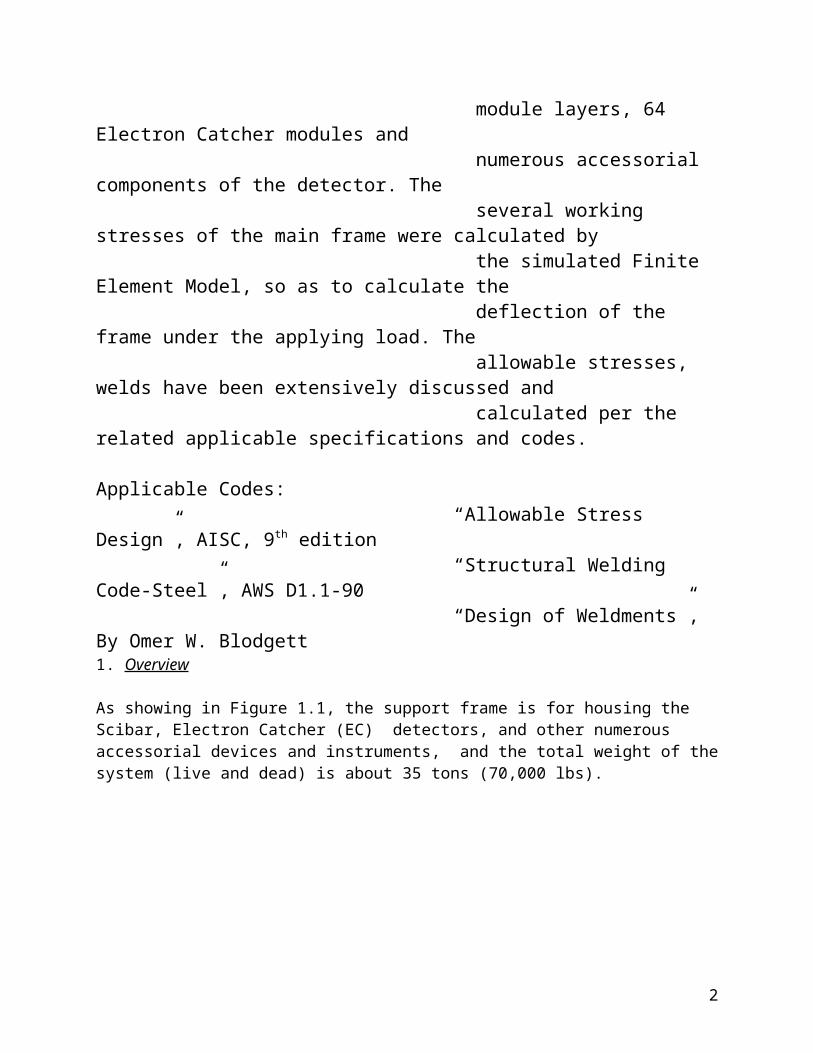
1. Overview
As showing in Figure 1.1, the support frame is for housing the Scibar, Electron Catcher (EC) detectors, and other numerous accessorial devices and instruments, and the total weight of the system (live and dead) is about 35 tons (70,000 lbs).
Fig. 1.1, The Isometric View of the Scibar and EC Detector of the SciBoone
For the simplicity, it is reasonable to assume that the structure of the main frame has to be designed to support the 35 tons applying load. The following page has more descriptions about the details of the applying load and the distributions.
The most critical load case for the main frame is that the main frame is lifted up for moving through four lifting pads at the top of the frame while all the components of the detector are installed in place. There is an extensive discussion regarding such loading case in section 3.
2

Fig. 1.2, The Support Frame of Scibar & EC Detectors. (2D drawing: ME-435903)
The Figure 1.2 is an iso. View of the frame and the mechanical drawing ME-435903 has detail specifications for the construction of the frame.
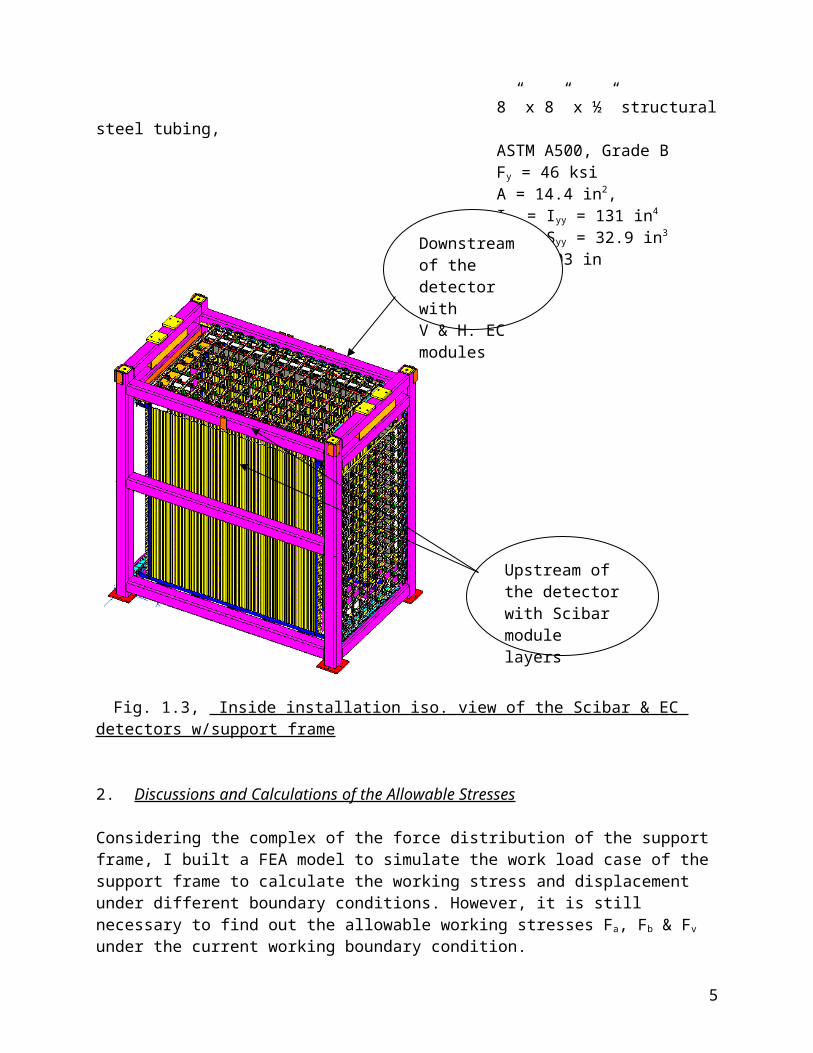
The 64 Scibar module layers are support by frame through 64 mounting brackets, the horizontal EC (with 32 modules) and the vertical EC (w/32 modules) are installed in the downstream of the support frame, figure 1.3 is showing the inside iso installation view of the support system without the dark room around.
The support frame is designed to be built by the steel structural tubing, the specifications of the steel tubing are:
8” x 8” x ½” structural steel tubing, ASTM A500, Grade B Fy = 46 ksi A = 14.4 in2, Ixx = Iyy = 131 in4
Sxx = Syy = 32.9 in3
Ґ = 3.03 in
3
Vertical supt. Column: 8x8x0.5Span Ly=126 in
Horizontal supt. Column: 8x8x0.5,Span Lx=140 in Lz=74.75 in

Fig. 1.3, Inside installation iso. view of the Scibar & EC detectors w/support frame
2. Discussions and Calculations of the Allowable Stresses
Considering the complex of the force distribution of the support frame, I built a FEA model to simulate the work load case of the support frame to calculate the working stress and displacement under different boundary conditions. However, it is still necessary to find out the allowable working stresses Fa, Fb & Fv under the current working boundary condition.
Assuming the square tube Lx=140 in (from fig. 1.2) under the loading case of “simple beam with uniformly distributed load” (#1 case of page 2-296, ASD 9th edition):
Per section B5.1d of ASD 9th edition, b = 8” – 3x0.5”= 6.50 in d = 8” tf = 0.5” = tw
Per table B5.1 of section B5: 190/(Fy)1/2 = 28 238/(Fy)1/2 = 35 b/t = 6.50/0.5 = 13 < 190/(Fy)1/2 = 28 < 238/(Fy)1/2 = 35
Per equation F1-2 of Sections F1.1 and eq. F1-5 of section F1.2:Lc = (76bf)/(Fy)1/2
4
Downstream of the detector with V & H. EC modules
Upstream of the detector with Scibar module layers
= (76 x 8 in) / (46ksi)1/2
= 89 in < Lx=140 inSo: Fb = 0.6 Fy
= 27.6 ksi
Per section F4 of ASD 9th edition:380 / /(Fy)1/2 = 56h = 8” – 2 x 0.5” = 7.0 inh/tw = 7 in/0.5 in =14 < 380/(Fy)1/2 = 56
Per eq F4-1 of section F4 of ASD 9th edition: Fv = 0.40 Fy
= 18.4 ksi
The allowable stress for the vertical square column tube Ly=126 in:Per section E2 of ASD 9th edition:Assuming K = 1.0 for the loading case of the support frame, then:
Cc = (2π2E / Fy )1/2
= 111 KL / ґ = 1.0 x 126 in / 3.03 in = 41.58 < Cc = 111
The allowable stress is: Fa = [1- (KL/ґ)2 / 2 Cc
2]Fy ÷ [5/3 + 3 (KL/ґ)/8Cc - (KL/ґ)3/8Cc3]
= [1- (41.58)2 / 2x1112]x 46 ksi ÷ [5/3 + 3x 41.58/8x111 - (41.58)3/8x 1113
= 42.77 ksi ÷ (1.667 + 0.14 – 0.00657) = 23.75 ksi
3. Discussios and Analysis of the FEM results:
As mentioned in section 2, several FEA models were built to simulating the main frame force loading conditions, and calculate the working stresses and displacements of the support frame under simulating boundary conditions of the frame. Fig. 3.1 is showing the model simulating the boundary conditions:
Due to the capacity of the computer, the model is assumed the boundary condition is symmetrical about the YZ plane @ where x=0.0, so it was use half of the frame. The mass weight of the frame Wf = 10,500 lbs (50% of it) is distributed through the frame
model. The forces from EC vertical modules, EC horizontal modules, 64 Scibar module layers,
vertical and top horizontal PMT assemblies, dark-house (6 sides with top side also acting as rated
5

service floor as shown in fig. 1) and other accessorial devices are distributed stimulatingly per the design and application of the whole detector support system.
Figure 3.1, The Boundary Conditions for the Subjected FEA Model (The main frame is lifted with the full detector components are loaded)
6

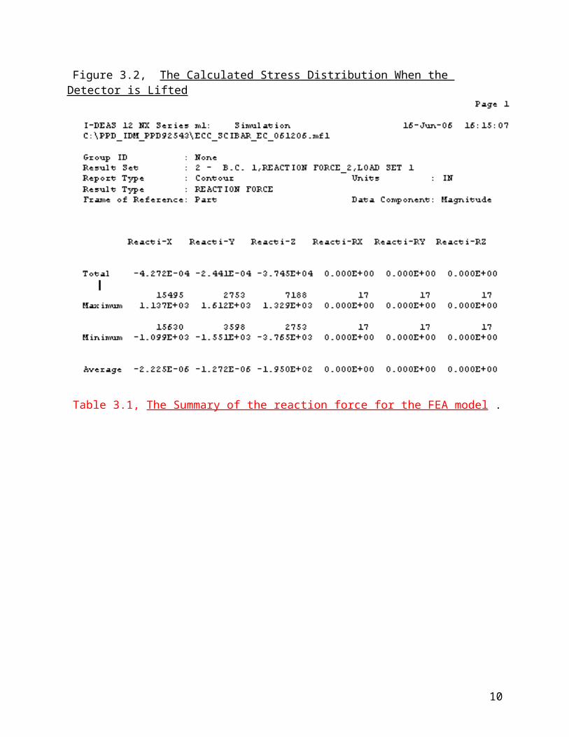
Figure 3.2, The Calculated Stress Distribution When the Detector is Lifted
7
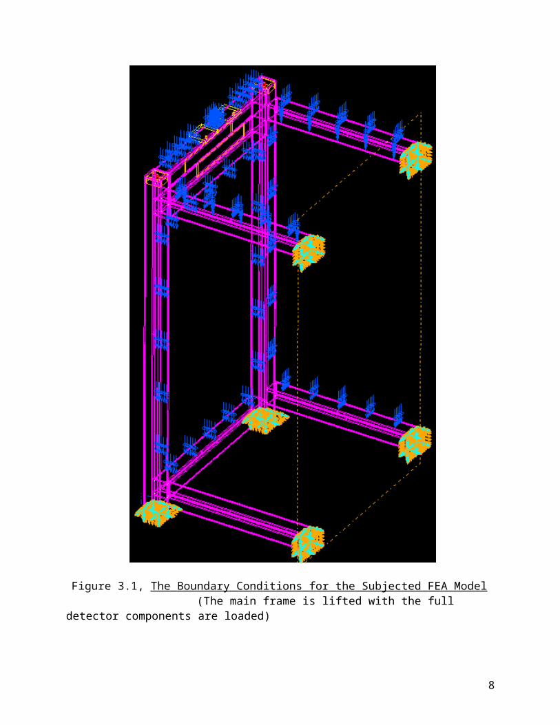
Table 3.1, The Summary of the reaction force for the FEA model .
Table 3.2, The Summary of the calculated stresses for the FEA model
8

It is found from Figure 3.2 that the max. Von Mises stress Fvm = 7.75 ksi which is less than the allowable stress Fa = 23.75 ksi. (see section2, page 5).
Table 3.2 summarized all max. & min. stresses in different directions from the simulated model. As you can see, all the values of the stress are less than the allowable stresses Fv and Fb respectively.
The deflections:The SciBooNE Experiment set the criteria of the deflection in Y direction (the direction of the gravitation) is +/- 0.059” (+/- 1.5 mm).From the Figure 3.2, it is found that the maximum deflection of the frame is about 0.0312”, which is less than the experimental defined value of 0.059”. 4. The discussions of the welds:
All welding metals are E70, where Fu = 70 ksiThen, the allowable stress of the welding metal: Fwv = 0.30 x 70 ksi = 21ksi (per Table J2.5, Chapter J, ASM, 9th edition)
The actual loading case for the tubing sections of the frame (ref. to fig. 1.2 of page 3, fig.1.3 of page 4 and fig. 3 of page 6) is between the “simple beam to the fixed beam at both ends, force uniformly distributed.” (See cases #1 & #15 of section 2, ASD, 9th edition).
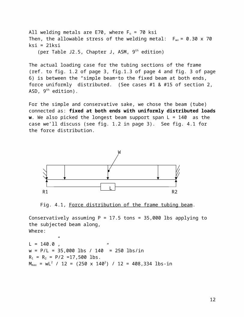
For the simple and conservative sake, we chose the beam (tube) connected as: fixed at both ends with uniformly distributed loads w. We also picked the longest beam support span L = 140” as the case we’ll discuss (see fig. 1.2 in page 3). See fig. 4.1 for the force distribution.
Fig. 4.1, Force distribution of the frame tubing beam.
Conservatively assuming P = 17.5 tons = 35,000 lbs applying to the subjected beam along,Where:
L = 140.0”, w = P/L = 35,000 lbs / 140” = 250 lbs/inR1 = R2 = P/2 =17,500 lbs.
R2R1
W
L
9
Mmax = wL2 / 12 = (250 x 1402) / 12 = 408,334 lbs-in
Figures 4.2 is partial view from the engineering drawing and figure 4.3 is the configuration of the tubing welds in cross view.
Fig. 4.2, The partial view of the main frame drawing ME-435903 (related to the tubing Weld in discussed area)
Figure 4.2. The weld configuration of the connect tubing beam to treat as lines
Find the geometric properties of the welds (treated as lines):
From figure 4,2, it is found that: Length L = 2 (b+d) = 32 in where b = 8 in = d Iz = Iy = d2 (3b + d) ÷ 6
10

= 341.33 in3 Sz = Sy = d (3b + d) ÷ 3 = 85.33 in2
Compute the components of the force in the welds:
The primary shear stress due to direct load fv
fv = R1 ÷ weld length =17,500 lbs ÷ 32.0 in = 547 lbs/in ↓
The bending stress fb about the Z axis:
fb = Mmax / Iz
= (408,334 ÷ 85.33) lbs/in = 4,786 lbs/in
The resultant force ft
ft = (fv2 + fb
2) 1/2 = (5472 + 4,7862)1/2 lbs/in = 4,817 lbs/in
Find the fillet weld size C, per drawing; all are fillet welds with E70 weld metal: Allowable stress of the weld metal Fwv: Fwv = 0.30 x 70 ksi = 21ksi, for E70 weld metal
The allowable weld size C:
C = ft / (0.707 x Fwv ) = 4,817 lbs/in ÷ (0.707 x 21,000) lbs/in2 = 0.3245 in
Per drawing ME-435903 (also see fig. 4.2), it was found that the weld sizes are 0.50”, so the design is satisfactory.
5. The conclusions:
The calculated working stresses are less than the allowable stress of the support frame; the calculated deflection values are less than the experimental designated deflection values; the designed welding sizes are much larger than the calculated required sizes. Up to those ends, the design of the main frame is satisfactory to the applying force distributions of the Scibar and Electron Catcher detector.
11
6. Some direct related reference drawings:
ME – 435903 -1ME – 435903 -2ME – 444071 -1ME – 444071 -2
In order to view more details of the drawings, please go to the link:http://home.fnal.gov/~edchi/SciBoone/EC_Scibar/drawings/
The site contains the master drawing list and the pdf format type of 2d drawings
12


![Dimensional Drawing - Grainger Industrial Supply · PDF fileDimensional Drawing Dayton Electric Mfg. Co. îìíðtXtX' ]vP U/v XdZ] ]PvuÇv} } ... CATALOG NO. PHASE TYPE FRAME 1TTB3BG](https://static.fdocuments.in/doc/165x107/5abade117f8b9a441d8c2550/dimensional-drawing-grainger-industrial-supply-drawing-dayton-electric-mfg-co.jpg)