Support design for tunnels with large overburden in weak rock
11
1 Support design for tunnels with large overburden in weak rock Wulf Schubert Institute of Rock Mechanics and Tunnelling, Graz University of Technology, NAWI Graz, Austria [email protected] Often damages of the lining and failure of bolts is a result of tunnelling in weak rock under high stresses. Large displacements can lead to violation of the clearance profile, requiring costly, dangerous, and time-consuming repairs. The main problem is that conventional supports have a rather limited strain tolerance. Shotcrete for example can tolerate maximum 0.6% to 0.8% strain without failure. Any imposed strains beyond this level will lead to destruction of the lining and consequently a more or less complete loss of support resistance, causing additional displacements and disintegration of the rock mass. Over the last two decades, ductile elements have been developed and successfully used on a considerable number of tunnels. The aim of those elements is optimally utilizing the capacity of the lining, while preventing damage of the lining by limiting the resistance. Although this sounds simple, the task of designing such a ductile lining system is not at all trivial. Many factors need to be considered, like development of the displacements in relation to face advance and time. The ground structure and the relative orientation between the tunnel axis and dominating geological features, like foliation or bedding strongly influence the longitudinal displacement profile. The development of the displacements over time also depends on the advance rate, influencing the degree of utilization of the shotcrete, which changes its properties over time. Currently used ductile element systems are presented and their characteristics as well as pros and cons discussed. More or less sophisticated tools for a preliminary design of ductile linings exist. Examples of application are presented. Another issue is the performance of grouted rock bolts under large strains. Installation of bolts at the time of the largest strain rates in the rock mass close to the face results in considerable shear strains in the grout, while it is setting. This may lead to a loss of bond between bolt and ground, making the bolts more or less ineffective. Special rib designs of the bolts can reduce this effect. INTRODUCTION It is well known that tunnelling in fault zones at a high primary stress level can lead to damages in the support (Figure 1), associated with at least partial loss of its resistance. This again leads to further disintegration of the ground and additional loss in its quality. Additional displacements or even a collapse may be the consequences. In addition costly, time consuming and hazardous repairs are required. Traditional methods to prevent damage to shotcrete linings are simply leaving gaps in the lining (Pöchhacker et al., Schubert, 1993, 1996). This pragmatic approach reduced the requirement for repairs, but resulted in a poor utilization of the shotcrete lining, thus leading to relatively large displacements (Figure 2). In addition, the system´s stability with such an approach heavily relies on the installed bolts. A tunnel collapse showed that the bond of grouted bolts can be significantly reduced by imposed large strains during the grout setting period (Schubert, 1995, Blümel, 1996). This accident triggered the development of improved grouted bolts and ductile lining systems. A first series of ductile elements, integrated into the shotcrete lining were used in 1994 at the Galgenbergtunnel in Austria (Schubert et al, 1996). Those relatively simple elements showed a strong variation in their resistance during the folding process. Improvements of the system followed, providing a more steady reaction of the elements (Moritz, 1999), but at the price of relatively high production effort and costs. Successful
Transcript of Support design for tunnels with large overburden in weak rock
1
Support design for tunnels with large overburden in
weak rock
Wulf Schubert Institute of Rock Mechanics and Tunnelling, Graz University of Technology,
NAWI Graz, Austria [email protected]
Often damages of the lining and failure of bolts is a result of tunnelling in weak rock under high stresses. Large displacements can lead to violation of the clearance profile, requiring
costly, dangerous, and time-consuming repairs. The main problem is that conventional supports have a rather limited strain tolerance.
Shotcrete for example can tolerate maximum 0.6% to 0.8% strain without failure. Any imposed strains beyond this level will lead to destruction of the lining and consequently a more or less complete loss of support resistance, causing additional displacements and
disintegration of the rock mass. Over the last two decades, ductile elements have been developed and successfully used on
a considerable number of tunnels. The aim of those elements is optimally utilizing the capacity of the lining, while preventing damage of the lining by limiting the resistance.
Although this sounds simple, the task of designing such a ductile lining system is not at all trivial. Many factors need to be considered, like development of the displacements in relation to face advance and time. The ground structure and the relative orientation
between the tunnel axis and dominating geological features, like foliation or bedding strongly influence the longitudinal displacement profile. The development of the
displacements over time also depends on the advance rate, influencing the degree of utilization of the shotcrete, which changes its properties over time. Currently used ductile element systems are presented and their characteristics as well as
pros and cons discussed. More or less sophisticated tools for a preliminary design of ductile linings exist. Examples of application are presented.
Another issue is the performance of grouted rock bolts under large strains. Installation of bolts at the time of the largest strain rates in the rock mass close to the face results in
considerable shear strains in the grout, while it is setting. This may lead to a loss of bond between bolt and ground, making the bolts more or less ineffective. Special rib designs of the bolts can reduce this effect.
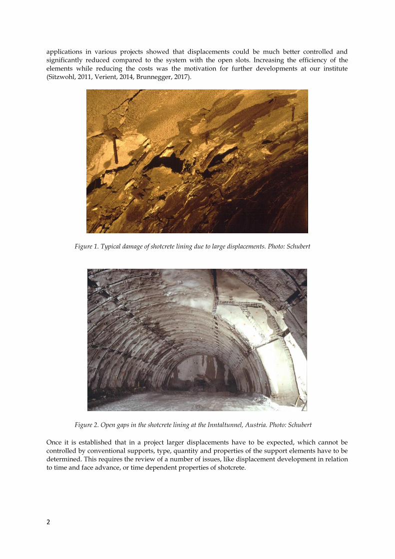
INTRODUCTION It is well known that tunnelling in fault zones at a high primary stress level can lead to damages in the
support (Figure 1), associated with at least partial loss of its resistance. This again leads to further
disintegration of the ground and additional loss in its quality. Additional displacements or even a
collapse may be the consequences. In addition costly, time consuming and hazardous repairs are
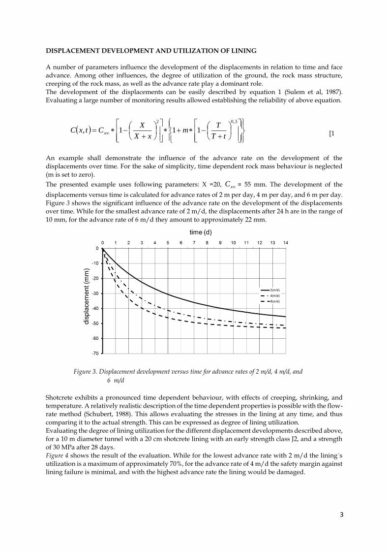
required. Traditional methods to prevent damage to shotcrete linings are simply leaving gaps in the
lining (Pöchhacker et al., Schubert, 1993, 1996). This pragmatic approach reduced the requirement for
repairs, but resulted in a poor utilization of the shotcrete lining, thus leading to relatively large
displacements (Figure 2). In addition, the system´s stability with such an approach heavily relies on the
installed bolts. A tunnel collapse showed that the bond of grouted bolts can be significantly reduced by
imposed large strains during the grout setting period (Schubert, 1995, Blümel, 1996). This accident
triggered the development of improved grouted bolts and ductile lining systems. A first series of ductile
elements, integrated into the shotcrete lining were used in 1994 at the Galgenbergtunnel in Austria
(Schubert et al, 1996). Those relatively simple elements showed a strong variation in their resistance
during the folding process. Improvements of the system followed, providing a more steady reaction of
the elements (Moritz, 1999), but at the price of relatively high production effort and costs. Successful
2
applications in various projects showed that displacements could be much better controlled and
significantly reduced compared to the system with the open slots. Increasing the efficiency of the
elements while reducing the costs was the motivation for further developments at our institute
(Sitzwohl, 2011, Verient, 2014, Brunnegger, 2017).
Figure 1. Typical damage of shotcrete lining due to large displacements. Photo: Schubert
Figure 2. Open gaps in the shotcrete lining at the Inntaltunnel, Austria. Photo: Schubert
Once it is established that in a project larger displacements have to be expected, which cannot be
controlled by conventional supports, type, quantity and properties of the support elements have to be
determined. This requires the review of a number of issues, like displacement development in relation
to time and face advance, or time dependent properties of shotcrete.
3
DISPLACEMENT DEVELOPMENT AND UTILIZATION OF LINING
A number of parameters influence the development of the displacements in relation to time and face
advance. Among other influences, the degree of utilization of the ground, the rock mass structure,
creeping of the rock mass, as well as the advance rate play a dominant role.
The development of the displacements can be easily described by equation 1 (Sulem et al, 1987).
Evaluating a large number of monitoring results allowed establishing the reliability of above equation.
[1
An example shall demonstrate the influence of the advance rate on the development of the
displacements over time. For the sake of simplicity, time dependent rock mass behaviour is neglected
(m is set to zero).
The presented example uses following parameters: X =20, xC = 55 mm. The development of the
displacements versus time is calculated for advance rates of 2 m per day, 4 m per day, and 6 m per day.
Figure 3 shows the significant influence of the advance rate on the development of the displacements
over time. While for the smallest advance rate of 2 m/d, the displacements after 24 h are in the range of
10 mm, for the advance rate of 6 m/d they amount to approximately 22 mm.
Figure 3. Displacement development versus time for advance rates of 2 m/d, 4 m/d, and
6 m/d
Shotcrete exhibits a pronounced time dependent behaviour, with effects of creeping, shrinking, and
temperature. A relatively realistic description of the time dependent properties is possible with the flow-
rate method (Schubert, 1988). This allows evaluating the stresses in the lining at any time, and thus
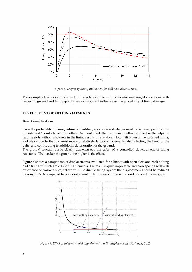
comparing it to the actual strength. This can be expressed as degree of lining utilization.
Evaluating the degree of lining utilization for the different displacement developments described above,
for a 10 m diameter tunnel with a 20 cm shotcrete lining with an early strength class J2, and a strength
of 30 MPa after 28 days.
Figure 4 shows the result of the evaluation. While for the lowest advance rate with 2 m/d the lining´s
utilization is a maximum of approximately 70%, for the advance rate of 4 m/d the safety margin against
lining failure is minimal, and with the highest advance rate the lining would be damaged.
3,02
111,tT
Tm
xX
XCtxC x
4
Figure 4. Degree of lining utilization for different advance rates
The example clearly demonstrates that the advance rate with otherwise unchanged conditions with
respect to ground and lining quality has an important influence on the probability of lining damage. DEVELOPMENT OF YIELDING ELEMENTS
Basic Considerations
Once the probability of lining failure is identified, appropriate strategies need to be developed to allow
for safe and “comfortable” tunnelling. As mentioned, the traditional method applied in the Alps by
leaving slots without shotcrete in the lining results in a relatively low utilization of the installed lining,
and also – due to the low resistance –to relatively large displacements, also affecting the bond of the
bolts, and contributing to additional deterioration of the ground.
The ground reaction curve clearly demonstrates the effect of a controlled development of lining
resistance. The weaker the ground the higher is the effect.
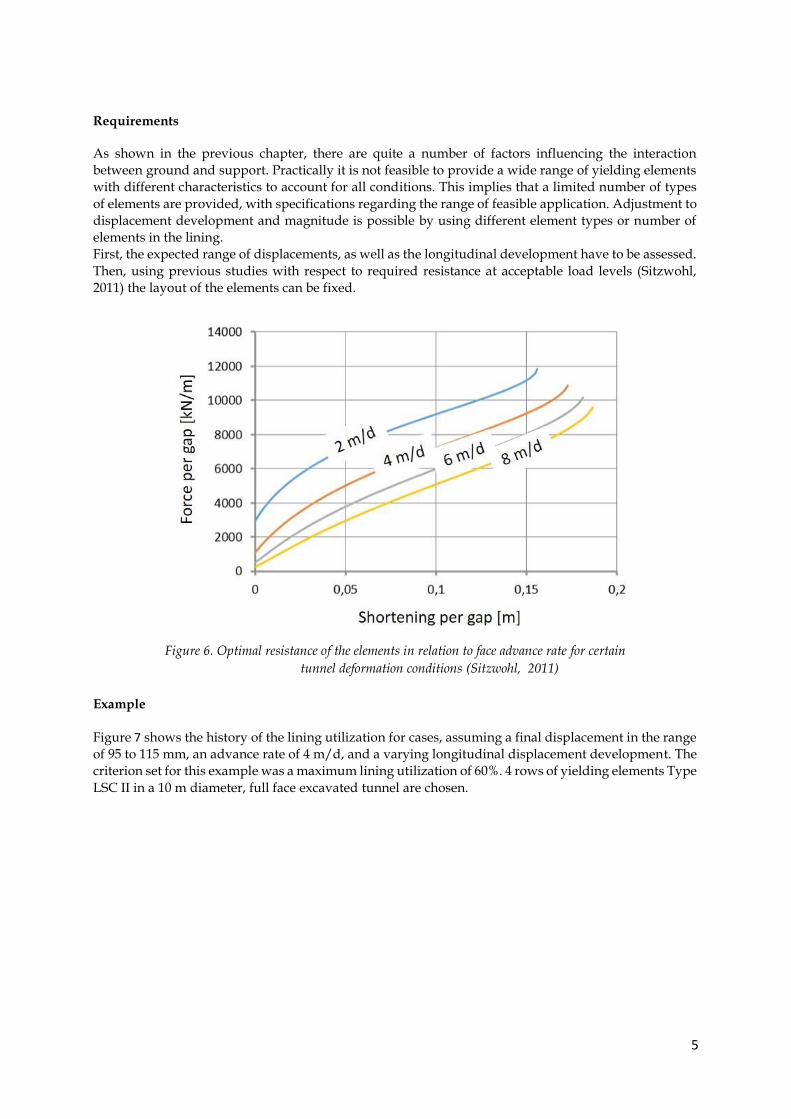
Figure 5 shows a comparison of displacements evaluated for a lining with open slots and rock bolting
and a lining with integrated yielding elements. The result is quite impressive and corresponds well with
experience on various sites, where with the ductile lining system the displacements could be reduced
by roughly 50% compared to previously constructed tunnels in the same conditions with open gaps.
Figure 5. Effect of integrated yielding elements on the displacements (Radoncic, 2011)
5
Requirements
As shown in the previous chapter, there are quite a number of factors influencing the interaction
between ground and support. Practically it is not feasible to provide a wide range of yielding elements
with different characteristics to account for all conditions. This implies that a limited number of types
of elements are provided, with specifications regarding the range of feasible application. Adjustment to
displacement development and magnitude is possible by using different element types or number of
elements in the lining.
First, the expected range of displacements, as well as the longitudinal development have to be assessed.
Then, using previous studies with respect to required resistance at acceptable load levels (Sitzwohl,
2011) the layout of the elements can be fixed.
Figure 6. Optimal resistance of the elements in relation to face advance rate for certain
tunnel deformation conditions (Sitzwohl, 2011)
Example
Figure 7 shows the history of the lining utilization for cases, assuming a final displacement in the range
of 95 to 115 mm, an advance rate of 4 m/d, and a varying longitudinal displacement development. The
criterion set for this example was a maximum lining utilization of 60%. 4 rows of yielding elements Type
LSC II in a 10 m diameter, full face excavated tunnel are chosen.
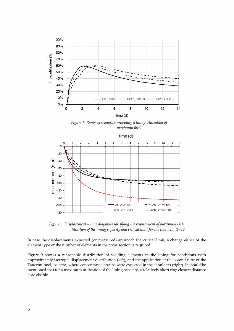
6
Figure 8. Displacement – time diagrams satisfying the requirement of maximum 60%
utilization of the lining capacity and critical limit for the case with X=12
In case the displacements expected (or measured) approach the critical limit, a change either of the
element type or the number of elements in the cross section is required.
Figure 9 shows a reasonable distribution of yielding elements in the lining for conditions with
approximately isotropic displacement distribution (left), and the application at the second tube of the
Tauerntunnel, Austria, where concentrated strains were expected in the shoulders (right). It should be
mentioned that for a maximum utilization of the lining capacity, a relatively short ring closure distance
is advisable.
Figure 7. Range of scenarios providing a lining utilization of
maximum 60%
7
Figure 9. Layout of yielding elements in the cross section (left), and application in the top
heading of the Tauerntunnel. Austria (right, Photo: Vergeiner)
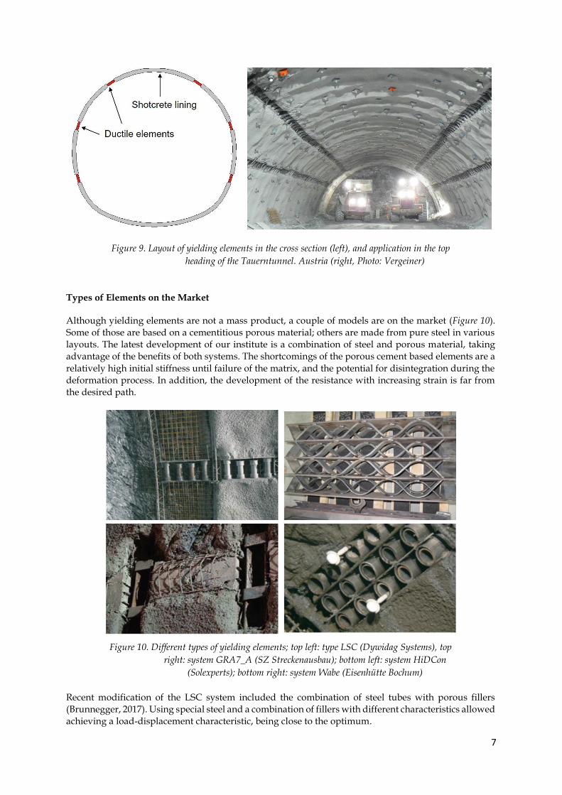
Types of Elements on the Market
Although yielding elements are not a mass product, a couple of models are on the market (Figure 10).
Some of those are based on a cementitious porous material; others are made from pure steel in various
layouts. The latest development of our institute is a combination of steel and porous material, taking
advantage of the benefits of both systems. The shortcomings of the porous cement based elements are a
relatively high initial stiffness until failure of the matrix, and the potential for disintegration during the
deformation process. In addition, the development of the resistance with increasing strain is far from
the desired path.
Figure 10. Different types of yielding elements; top left: type LSC (Dywidag Systems), top
right: system GRA7_A (SZ Streckenausbau); bottom left: system HiDCon
(Solexperts); bottom right: system Wabe (Eisenhütte Bochum)
Recent modification of the LSC system included the combination of steel tubes with porous fillers
(Brunnegger, 2017). Using special steel and a combination of fillers with different characteristics allowed
achieving a load-displacement characteristic, being close to the optimum.
8
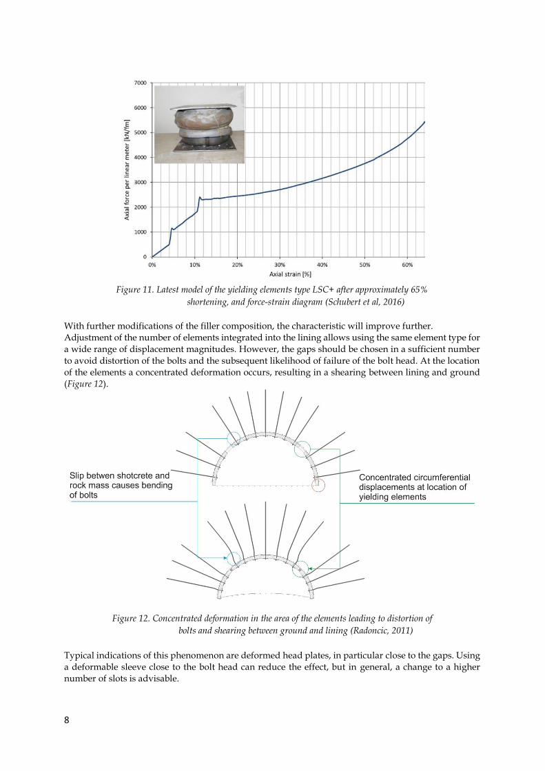
Figure 11. Latest model of the yielding elements type LSC+ after approximately 65%
shortening, and force-strain diagram (Schubert et al, 2016)
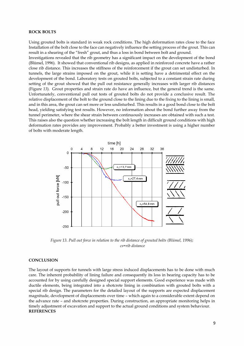
With further modifications of the filler composition, the characteristic will improve further.
Adjustment of the number of elements integrated into the lining allows using the same element type for
a wide range of displacement magnitudes. However, the gaps should be chosen in a sufficient number
to avoid distortion of the bolts and the subsequent likelihood of failure of the bolt head. At the location
of the elements a concentrated deformation occurs, resulting in a shearing between lining and ground
(Figure 12).
Figure 12. Concentrated deformation in the area of the elements leading to distortion of
bolts and shearing between ground and lining (Radoncic, 2011)
Typical indications of this phenomenon are deformed head plates, in particular close to the gaps. Using
a deformable sleeve close to the bolt head can reduce the effect, but in general, a change to a higher
number of slots is advisable.
9
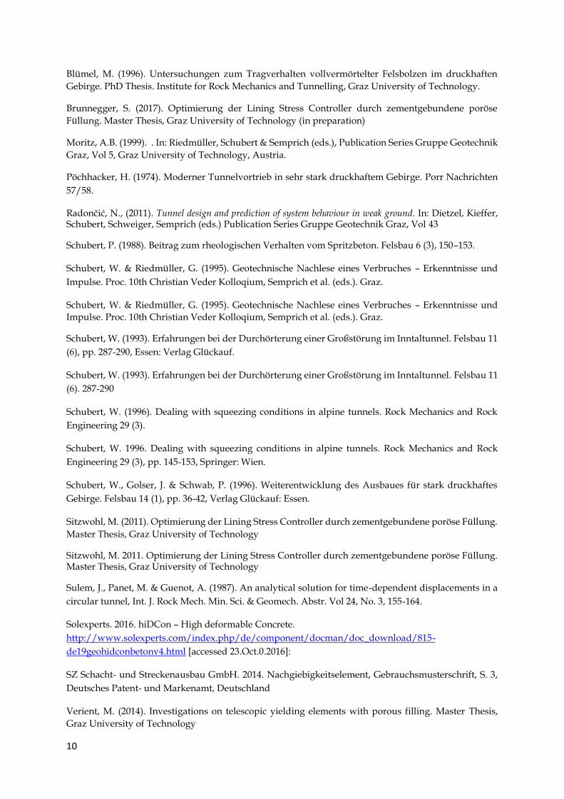
ROCK BOLTS
Using grouted bolts is standard in weak rock conditions. The high deformation rates close to the face
Installation of the bolt close to the face can negatively influence the setting process of the grout. This can
result in a shearing of the “fresh” grout, and thus a loss in bond between bolt and ground.
Investigations revealed that the rib geometry has a significant impact on the development of the bond
(Blümel, 1996). It showed that conventional rib designs, as applied in reinforced concrete have a rather
close rib distance. This increases the stiffness of the reinforcement if the grout can set undisturbed. In
tunnels, the large strains imposed on the grout, while it is setting have a detrimental effect on the
development of the bond. Laboratory tests on grouted bolts, subjected to a constant strain rate during
setting of the grout showed that the pull out resistance generally increases with larger rib distances
(Figure 13). Grout properties and strain rate do have an influence, but the general trend is the same.
Unfortunately, conventional pull out tests of grouted bolts do not provide a conclusive result. The
relative displacement of the bolt to the ground close to the lining due to the fixing to the lining is small,
and in this area, the grout can set more or less undisturbed. This results in a good bond close to the bolt
head, yielding satisfying test results. However, no information about the bond further away from the
tunnel perimeter, where the shear strain between continuously increases are obtained with such a test.
This raises also the question whether increasing the bolt length in difficult ground conditions with high
deformation rates provides any improvement. Probably a better investment is using a higher number
of bolts with moderate length.
Figure 13. Pull out force in relation to the rib distance of grouted bolts (Blümel, 1996);
cs=rib distance
CONCLUSION The layout of supports for tunnels with large stress induced displacements has to be done with much
care. The inherent probability of lining failure and consequently its loss in bearing capacity has to be
accounted for by using carefully designed special support elements. Good experience was made with
ductile elements, being integrated into a shotcrete lining in combination with grouted bolts with a
special rib design. The parameters for the detailed layout of the supports are expected displacement
magnitude, development of displacements over time – which again to a considerable extent depend on
the advance rate – and shotcrete properties. During construction, an appropriate monitoring helps in
timely adjustment of excavation and support to the actual ground conditions and system behaviour. REFERENCES
10
Blümel, M. (1996). Untersuchungen zum Tragverhalten vollvermörtelter Felsbolzen im druckhaften
Gebirge. PhD Thesis. Institute for Rock Mechanics and Tunnelling, Graz University of Technology.
Brunnegger, S. (2017). Optimierung der Lining Stress Controller durch zementgebundene poröse
Füllung. Master Thesis, Graz University of Technology (in preparation)
Moritz, A.B. (1999). . In: Riedmüller, Schubert & Semprich (eds.), Publication Series Gruppe Geotechnik
Graz, Vol 5, Graz University of Technology, Austria.
Pöchhacker, H. (1974). Moderner Tunnelvortrieb in sehr stark druckhaftem Gebirge. Porr Nachrichten
57/58.
Radončić, N., (2011). Tunnel design and prediction of system behaviour in weak ground. In: Dietzel, Kieffer, Schubert, Schweiger, Semprich (eds.) Publication Series Gruppe Geotechnik Graz, Vol 43
Schubert, P. (1988). Beitrag zum rheologischen Verhalten vom Spritzbeton. Felsbau 6 (3), 150–153.
Schubert, W. & Riedmüller, G. (1995). Geotechnische Nachlese eines Verbruches – Erkenntnisse und
Impulse. Proc. 10th Christian Veder Kolloqium, Semprich et al. (eds.). Graz.
Schubert, W. & Riedmüller, G. (1995). Geotechnische Nachlese eines Verbruches – Erkenntnisse und
Impulse. Proc. 10th Christian Veder Kolloqium, Semprich et al. (eds.). Graz.
Schubert, W. (1993). Erfahrungen bei der Durchörterung einer Großstörung im Inntaltunnel. Felsbau 11
(6), pp. 287-290, Essen: Verlag Glückauf.
Schubert, W. (1993). Erfahrungen bei der Durchörterung einer Großstörung im Inntaltunnel. Felsbau 11
(6). 287-290
Schubert, W. (1996). Dealing with squeezing conditions in alpine tunnels. Rock Mechanics and Rock
Engineering 29 (3).
Schubert, W. 1996. Dealing with squeezing conditions in alpine tunnels. Rock Mechanics and Rock
Engineering 29 (3), pp. 145-153, Springer: Wien.
Schubert, W., Golser, J. & Schwab, P. (1996). Weiterentwicklung des Ausbaues für stark druckhaftes
Gebirge. Felsbau 14 (1), pp. 36-42, Verlag Glückauf: Essen.
Sitzwohl, M. (2011). Optimierung der Lining Stress Controller durch zementgebundene poröse Füllung.
Master Thesis, Graz University of Technology
Sitzwohl, M. 2011. Optimierung der Lining Stress Controller durch zementgebundene poröse Füllung. Master Thesis, Graz University of Technology
Sulem, J., Panet, M. & Guenot, A. (1987). An analytical solution for time-dependent displacements in a
circular tunnel, Int. J. Rock Mech. Min. Sci. & Geomech. Abstr. Vol 24, No. 3, 155-164.
Solexperts. 2016. hiDCon – High deformable Concrete.
http://www.solexperts.com/index.php/de/component/docman/doc_download/815-
de19geohidconbetonv4.html [accessed 23.Oct.0.2016]:
SZ Schacht- und Streckenausbau GmbH. 2014. Nachgiebigkeitselement, Gebrauchsmusterschrift, S. 3,
Deutsches Patent- und Markenamt, Deutschland
Verient, M. (2014). Investigations on telescopic yielding elements with porous filling. Master Thesis,
Graz University of Technology
11
Authors CV
Prof. Wulf Schubert
Full Professor
Institute of Rock Mechanics and Tunnelling
Graz University of Technology
Mr. Wulf Schubert is full professor and head of the Institute of Rock Mechanics and Tunnelling at the Graz University of Technology since 1992 and founding partner of 3G Gruppe Geotechnik Graz Consulting Engineers. He is a tunnelling expert with international experience. Besides his lectures in the field of rock mechanics and tunnelling in bachelor and master courses, he supervised more than 70 master theses and 20 dissertations. Additionally he is programme director and lecturer of a university programme in NATM Engineering.