Supplementary Operating Manual · 2019-10-01 · 1 Supplementary Operating Manual. Double...
12
Double Mechanical Seals Tandem Arrangement with Quench Liquid Supplementary Operating Manual
Transcript of Supplementary Operating Manual · 2019-10-01 · 1 Supplementary Operating Manual. Double...

Double Mechanical Seals
Tandem Arrangementwith Quench Liquid
Supplementary OperatingManual

Legal information/Copyright
Supplementary Operating Manual Double Mechanical Seals
Original operating manual
All rights reserved. The contents provided herein must neither be distributed, copied, reproduced,edited or processed for any other purpose, nor otherwise transmitted, published or made available to athird party without the manufacturer's express written consent.
Subject to technical modification without prior notice.
© KSB SE & Co. KGaA, Frankenthal 19/01/2018

Contents
3 of 12Double Mechanical Seals
Contents
1 Supplementary Operating Manual ....................................................................................................... 41.1 General.............................................................................................................................................................. 41.2 Technical data................................................................................................................................................... 41.3 Removing the shaft seal................................................................................................................................... 4
1.3.1 Removing the shaft seal – shaft unit 17 ............................................................................................. 41.3.2 Removing the shaft seal – shaft units 25/35....................................................................................... 5
1.4 Installing the shaft seal .................................................................................................................................... 51.4.1 Installing the shaft seal – shaft unit 17............................................................................................... 61.4.2 Installing the shaft seal – shaft units 25/35 ........................................................................................ 6
1.5 Quench liquid ................................................................................................................................................... 71.5.1 Applications.......................................................................................................................................... 71.5.2 Quench pot arrangement.................................................................................................................... 71.5.3 Quench liquid requirements ............................................................................................................... 7
1.6 General assembly drawing with list of components ...................................................................................... 91.6.1 Shaft unit 17......................................................................................................................................... 91.6.2 Shaft unit 25/35.................................................................................................................................. 10

1 Supplementary Operating Manual
4 of 12 Double Mechanical Seals
1 Supplementary Operating Manual
1.1 GeneralThis supplementary operating manual accompanies the installation/operatingmanual. All information contained in the installation/operating manual must beobserved.
Table 1: Relevant operating manuals
Type series Reference number of the installation/operatingmanual
Etaprime L 2753.81
Etaprime B 2753.82
1.2 Technical dataDesign details The shaft is sealed by two balanced single bi-directional mechanical seals to EN 12756
in tandem arrangement with quench liquid.
Seal size/ material variant Table 2: Material variant
Shaf
t u
nit Mechanical seal
Outboard (433.02) Inboard (433.01)
Seal size Materialvariant
Seal size Materialvariant
17 016S-MG1-G60 Q1Q1EGG 035S-MG1-SX-GX1) Q1Q1EGG
25 KU028S-MG12-G6-E1 Q1Q1EGG-G KU028S-MG12-G6-E1 Q1Q1EGG-G
35 KU038S-MG12-G6-E1 Q1Q1EGG-G KU038S-MG12-G6-E1 Q1Q1EGG-G
Material code Table 3: Material code
Item Description Code Materials
1 Primary ring Q1 SiC, silicon carbide, sinteredwithout pressure
2 Mating ring Q1 SiC, silicon carbide, sinteredwithout pressure
3 Secondary seal E Ethylene propylene rubber(EPDM 80)
4 Spring G CrNiMo steel
5 Other components G CrNiMo steel
1.3 Removing the shaft seal
1.3.1 Removing the shaft seal – shaft unit 17
1. Dismantle the pump as described in operating manual 2753.81 or 2753.82.
2. Take off hexagon nut 920.95, impeller 230 and disc 550.02/.04.
3. Take key 940.01 out of the shaft keyway.
4. Remove fitting 720.13/.14.
5. Pull primary ring carrier 473 with inboard mechanical seal 433.01 (rotatingassembly) off shaft 210.
6. Pull the rotating assembly of outboard mechanical seal 433.02 off shaft 210.
7. Remove the stationary mating ring of mechanical seal 433.01/.02 from drivelantern 341.
8. Pull inboard mechanical seal 433.01 (rotating assembly) off primary ring carrier473.
1) Dimension not compliant with EN 12756

1 Supplementary Operating Manual
5 of 12Double Mechanical Seals
1.3.2 Removing the shaft seal – shaft units 25/35
ü Dismantle the pump as described in operating manual 2753.81 or 2753.82.
ü The back pull-out unit has been placed in a clean and level assembly area.
1. Take hexagon nut 920.95, disc 550.95 (shaft unit 25 only), safety device 930.95,impeller 230 and discs 550.02/.04 off shaft 210.
2. Take key 940.01 out of the shaft keyway.
3. Remove spacer sleeve 525 (shaft unit 35 only) from shaft 210.
4. Remove fitting 720.13/.14 and joint ring 411.13/.14 from seal cover 471.
5. Undo hexagon nut 920.02 on seal cover 471. Slide the seal cover against thebearing bracket or motor.
6. On models with a clamped casing cover: Undo and remove bolt 901.98 (long-coupled design) or screw 914.22 (close-coupled design). Separate casing cover161 from the locating fit of bearing bracket 330 or from the locating fit of drivelantern 341, as applicable. Pull it off shaft 210.On models with a bolted casing cover: Undo hexagon nut 920.15. Use forcingscrews 901.31 to separate casing cover 161 from bearing bracket 330 or drivelantern 341. Pull it off shaft 210.
7. Pull shaft sleeve 523 with inboard mechanical seal 433.01, intermediate ring 509and the rotating assembly of outboard mechanical seal 433.02 off shaft 210.
8. Remove seal cover 471 with the mating ring of outboard mechanical seal 433.02from shaft 210.
9. Remove inboard mechanical seal 433.01 and intermediate ring 509 from shaftsleeve 523.
10. Pull the rotating assembly of outboard mechanical seal 433.02 with the thrustring off shaft sleeve 523.
11. Remove the stationary mating ring of mechanical seal 433.01 and O-rings 412.15from intermediate ring 509.
12. Remove the stationary mating ring of mechanical seal 433.02 from seal cover471.
13. Remove gasket 400.75 from the shaft and dispose of it.
1.4 Installing the shaft sealInstalling the
mechanical sealThe following rules must be observed when installing the mechanical seal:
▪ Work cleanly and accurately.
▪ Only remove the protective wrapping of the contact faces immediately beforeinstallation takes place.
▪ Prevent any damage to the sealing surfaces or O-rings.
ü Observe / carry out the notes and steps given in operating manual 2753.81/.82.
ü The bearing assembly as well as the individual parts have been placed in a cleanand level assembly area.
ü All dismantled parts have been cleaned and checked for wear.
ü Any damaged or worn parts have been replaced by original spare parts.
ü The sealing surfaces have been cleaned.
1. Clean the shaft, the shaft sleeve and the mating ring locations in drive lantern341, seal cover 471 as well as intermediate ring 509. Gently remove any deposits.If score marks or scratches are still visible, replace the affected parts.
NOTE
To reduce friction forces when assembling the seal, wet the shaft sleeve and thelocation of the stationary ring with water.

1 Supplementary Operating Manual
6 of 12 Double Mechanical Seals
1.4.1 Installing the shaft seal – shaft unit 17
1. Press the mating ring of outboard mechanical seal 433.02 and the mating ringof inboard mechanical seal 433.01 into drive lantern 341. Make sure that pressure is applied evenly, using hands or fingers only.
2. Slide outboard mechanical seal 433.02 (rotating assembly) onto shaft 210.
3. Slide inboard mechanical seal 433.01 (rotating assembly) onto primary ringcarrier 473 until it will not go any further.
4. Slide primary ring carrier 473 with assembled mechanical seal 433.01 onto shaft210.
5. Place key 940.01 into the keyway of shaft 210.
6. Slide disc 550.02/550.04 and impeller 230 onto shaft 210. Tighten with hexagonnut 920.95.
7. Mount fittings 720.13/.14 in drive lantern 341 using Loctite 573 and hemp.
1.4.2 Installing the shaft seal – shaft units 25/35
1. Fit the rotating assembly of outboard mechanical seal 433.02 with the suppliedthrust ring on shaft sleeve 523.
CAUTION
Elastomers in contact with oil/greaseShaft seal failure!
▷ Use water as assembly lubricant.
▷ Never use oil or grease as assembly lubricant.
2. Carefully position the stationary assembly of mechanical seal 433.02 with the O-ring in seal cover 471. Make sure that pressure is applied evenly.
3. Slide seal cover 471 onto shaft 210 until it rests against bearing bracket 330 orthe motor.
4. Carefully position the stationary assembly of mechanical seal 433.01 with the O-ring in intermediate ring 509. Make sure that pressure is applied evenly.
5. Insert O-rings 412.15 into seal cover 509.
6. Fit intermediate ring 509 with O-rings 412.15 and the stationary assembly ofmechanical seal 433.01 in casing cover 161.
7. Slide shaft sleeve 523 together with the rotating assembly of mechanical seal433.02 and new gasket 400.75 onto shaft 210.
8. On models with a bolted casing cover: Screw back forcing screws 901.31 but donot remove them. Slide casing cover 161 with intermediate ring 509 ontobearing bracket 330 or drive lantern 341. While doing so, carefully slide sealcover 471 into casing cover 161. On models with a clamped casing cover: Slide casing cover 161 withintermediate ring 509 onto bearing bracket 330 or drive lantern 341. Whiledoing so, carefully slide seal cover 471 into casing cover 161. Insert bolts 901.98(long-coupled design) or screws 914.22 (close-coupled design) and tighten tofasten casing cover 161 in place.
9. Fit and tighten nuts 920.15 at casing cover 161.
10. Slide the rotating assembly of mechanical seal 433.01 onto shaft sleeve 523.
11. Slide spacer sleeve 525 (shaft unit 35 only) onto shaft 210.
12. Place key 940.01 in the shaft keyway.
13. Slide discs 550.02/.04, impeller 230, disc 550.95 (shaft unit 25 only) and safetydevice 930.95 onto shaft 210. Fasten with hexagon nut 920.95.
14. Position fittings 720.13/.14 with joint rings 411.13/.14 in seal cover 471 andtighten.
15. Carry out all other relevant steps given in operating manual 2753.81 or 2753.82,as applicable.

1 Supplementary Operating Manual
7 of 12Double Mechanical Seals
1.5 Quench liquid
1.5.1 Applications
A quench liquid is used in the following cases:
▪ Where a single mechanical seal without supportive measures would not work atall or unsatisfactorily.
▪ Where a double mechanical seal design with pressurised barrier fluid is notrequired.
1.5.2 Quench pot arrangement
~ 1 m
24A 24E
UG1323255-002_003/03
Fig. 1: Quench pot arrangement
Table 4: Connections
Connection2) Description Size3)
24A Quench liquid outlet G 1/4
24E Quench liquid inlet G 1/4
Quench liquid from quench pots arranged above the seal: liquid circulated by meansof thermosyphon effect or forced circulation.
1.5.3 Quench liquid requirements
The quench liquid should preferably form a solution with the pumped product andbe environmentally compatible.
Typical quench liquids ▪ Water with a conductivity of 100 - 800 µS/cm
▪ Water-glycol mixture
▪ Glycerine
2) Plugged during transport3) To ISO 228

1 Supplementary Operating Manual
8 of 12 Double Mechanical Seals
The quench liquid should be supplied to the mechanical seals without pressure(atmospheric pressure), if possible. Positive pressures of up to 0.5 bar are acceptable.
The one-way quench supply should be adjusted to a constant flow ≥ 0.4 l/min.
Periodically check the quench liquid for contamination (replace quench liquid andclean quench system if necessary).
1 Supplementary Operating Manual
9 of 12Double Mechanical Seals
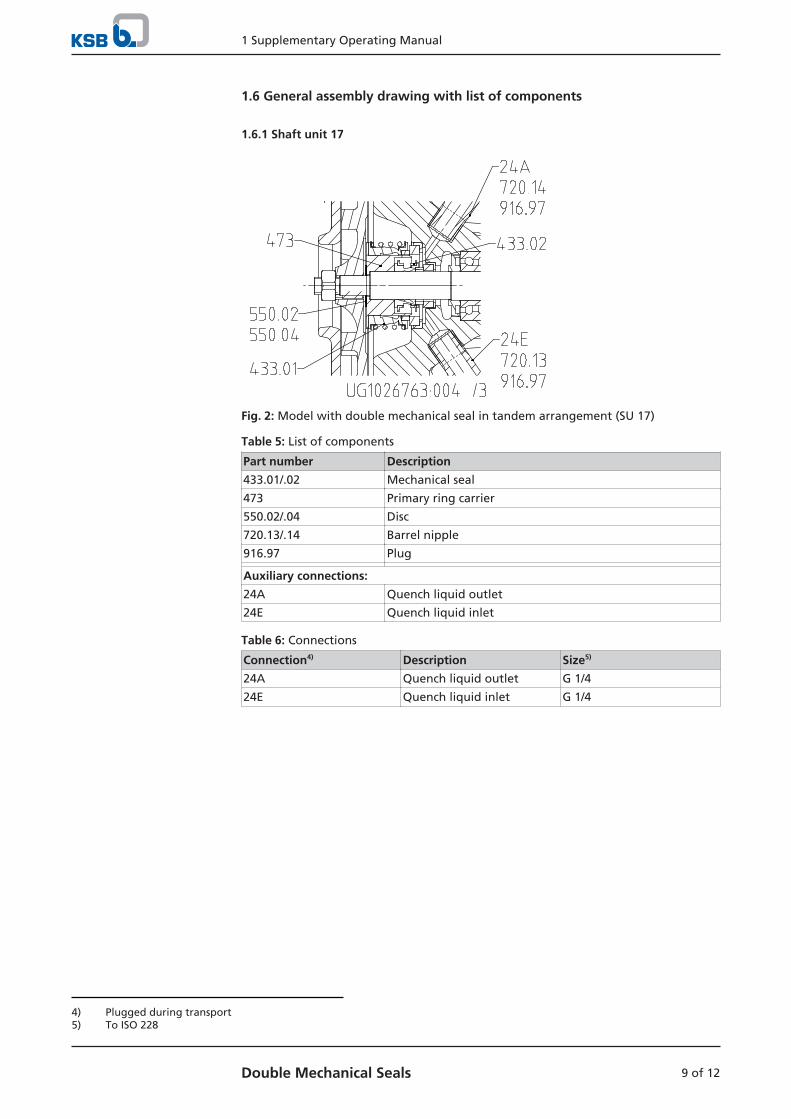
1.6 General assembly drawing with list of components
1.6.1 Shaft unit 17
Fig. 2: Model with double mechanical seal in tandem arrangement (SU 17)
Table 5: List of components
Part number Description
433.01/.02 Mechanical seal
473 Primary ring carrier
550.02/.04 Disc
720.13/.14 Barrel nipple
916.97 Plug
Auxiliary connections:
24A Quench liquid outlet
24E Quench liquid inlet
Table 6: Connections
Connection4) Description Size5)
24A Quench liquid outlet G 1/4
24E Quench liquid inlet G 1/4
4) Plugged during transport5) To ISO 228

1 Supplementary Operating Manual
10 of 12 Double Mechanical Seals
1.6.2 Shaft unit 25/35
Fig. 3: Model with double mechanical seal in tandem arrangement (SU 25/35)
Table 7: List of components
Part number Description
161 Casing cover
400.75 Gasket
412.15 O-ring
411.13/.14 Joint ring
433.01/.02 Mechanical seal
471 Seal cover
509 Intermediate ring
523 Shaft sleeve
525 Spacer sleeve
562.25 Parallel pin
720.13/.14 Fitting
902.02 Stud
920.02 Hexagon nut
Auxiliary connections:
24A Quench liquid outlet
24E Quench liquid inlet

1 Supplementary Operating Manual
11 of 12Double Mechanical Seals
Table 8: Connections
Connection6) Description Size7)
24A Quench liquid outlet G 1/4
24E Quench liquid inlet G 1/4
6) Plugged during transport7) To ISO 228

KSB SE & Co. KGaA
Johann-Klein-Straße 9 • 67227 Frankenthal (Germany)
Tel. +49 6233 86-0
www.ksb.com
2753
.811
/02-
EN(0
1688
149)