
Supplementary notes for EE-201 - Saadat · Supplementary notes for EE-201 (H. Saadat) ... Go to...
13
1 Supplementary notes for EE-201 (H. Saadat) POWER IN SINGLE-PHASE AC CIRCUITS Figure 1 shows a single-phase sinusoidal voltage supplying a load. - + FIGURE 1 Sinusoidal source supplying a load. Let the instantaneous voltage be (1) and the instantaneous current be given by (2) The instantaneous power delivered to the load is the product of voltage and current given by (3) It is informative to write (3) in another form using the trigonometric identities, the result is Energy flow into Energy borrowed and the circuit returned by the circuit (4) where is the angle between voltage and current, or the impedance angle. is positive if the load is inductive, (i.e., current is lagging the voltage) and is negative if the load is capacitive (i.e., current is leading the voltage). and . For , , , and (inductive load), we use the following commands to plot , , and , , and .
Transcript of Supplementary notes for EE-201 - Saadat · Supplementary notes for EE-201 (H. Saadat) ... Go to...

1
Supplementary notes for EE-201 (H. Saadat)
POWER IN SINGLE-PHASE AC CIRCUITS
Figure 1 shows a single-phase sinusoidal voltage supplying a load.
b
b -
v(t)
-
+i(t)
FIGURE 1Sinusoidal source supplying a load.
Let the instantaneous voltage be
v(t) = Vm cos(!t+ �v) (1)
and the instantaneous current be given by
i(t) = Im cos(!t+ �i) (2)
The instantaneous power p(t) delivered to the load is the product of voltage v(t)and current i(t) given by
p(t) = v(t) i(t) = VmIm cos(!t+ �v) cos(!t+ �i) (3)
It is informative to write (3) in another form using the trigonometric identities, theresult is
p(t) = jV jjIj cos �[1 + cos 2(!t+ �v)]| {z }pR(t)
+ jV jjIj sin � sin 2(!t+ �v)| {z }pX(t)
Energy flow into Energy borrowed andthe circuit returned by the circuit
(4)
where � is the angle between voltage and current, or the impedance angle. � ispositive if the load is inductive, (i.e., current is lagging the voltage) and � is negativeif the load is capacitive (i.e., current is leading the voltage). jV j = Vm=
p2 and
jIj = Im=p2 .
For Vm = 1, Im = 0:8, �v = 0, and �i = ��=3 (inductive load), we use thefollowing commands to plot v(t), i(t), and p(t), pr(t), and px(t).
Hadi
Text Box
Go to Power System Analysis Home Page - PSA Publishing

2
wt=0:.05:3*pi;Vm = 1; Im = 0.8;thetav=0; thetai = -pi/3; theta=thetav-thetai;v = Vm*cos(wt); i = Im*cos(wt + thetai);p = v.*i;pr = Vm*Im/2*cos(theta)*(1+cos(2*(wt+thetav)));px = Vm*Im/2*sin(theta)*sin(2*(wt+thetav));subplot(2, 1, 1),plot(wt, v, wt, i, wt, p), gridtitle('v(t) = V_mcos\omegat, i(t) = I_mcos(\omegat - 60)')xlabel('\omega t, rad/s')text(1.4, .85, 'i'), text(3.5, .75, 'p'), text(.1, .85, 'v')subplot(2, 1, 2),plot(wt, pr, wt, px), gridtext(.8, .45, 'p_x'), text(2.3, .45, 'p_r')xlabel('\omega t, rad/s')
The result in shown in Figure 2.
0 1 2 3 4 5 6 7 8 9 10−1
−0.5
0
0.5
1
v(t) = Vm
cosωt, i(t) = Im
cos(ωt − 60)
ω t, rad/s
i pv
0 1 2 3 4 5 6 7 8 9 10−0.4
−0.2
0
0.2
0.4
0.6p
xp
r
ω t, rad/s
Figure 2 plots of v(t), i(t), p(t), pr(t), and px(t) for inductive load � = �=3.

3
pR(t) = jV jjIj cos � + jV jjIj cos � cos 2(!t+ �v)] (5)
The second term in (5), which has a frequency twice that of the source, accountsfor the sinusoidal variation in the absorption of power by the resistive portion ofthe load. Since the average value of this sinusoidal function is zero, the averagepower delivered to the load is given by
P = jV jjIj cos � (6)
This is the power absorbed by the resistive component of the load and is also re-ferred to as the active power or real power. The product of the rms voltage valueand the rms current value jV jjIj is called the apparent power and is measured inunits of volt ampere. The product of the apparent power and the cosine of the anglebetween voltage and current yields the real power. Because cos � plays a key role inthe determination of the average power, it is called power factor. When the currentlags the voltage, the power factor is considered lagging. When the current leads thevoltage, the power factor is considered leading.
The second component of (4)
pX(t) = jV jjIj sin � sin 2(!t+ �v) (7)
pulsates with twice the frequency and has an average value of zero. This compo-nent accounts for power oscillating into and out of the load because of its reactiveelement (inductive or capacitive). The amplitude of this pulsating power is calledreactive power and is designated by Q.
Q = jV jjIj sin � (8)
Both P and Q have the same dimension. However, in order to distinguish betweenthe real and the reactive power, the term “var” is used for the reactive power (var isan acronym for the phrase “volt-ampere reactive”). For an inductive load, current islagging the voltage, � = (�v � �i) > 0 and Q is positive; whereas, for a capacitiveload, current is leading the voltage, � = (�v � �i) < 0 and Q is negative.The plot of instantaneous current i(t), voltage, v(t), powers p(t), pr(t), and px(t),for a capacitive load with �i = �=3 , � = �v � �i = ��=3 is shown in Figure 3.

4
0 1 2 3 4 5 6 7 8 9 10−1
−0.5
0
0.5
1
v(t) = Vm
cosωt, i(t) = Im
cos(ωt + 60)
ω t, rad/s
vpi
0 1 2 3 4 5 6 7 8 9 10−0.4
−0.2
0
0.2
0.4
0.6
pr
px
ω t, rad/s
Figure 3 plots of v(t), i(t), p(t), pr(t), and px(t) for capacitive load � = ��=3.
The plots for a purely resistive load, i.e., � = 0 = is shown in Figure 4.

5
0 1 2 3 4 5 6 7 8 9 10−1
−0.5
0
0.5
1
v(t) = Vm
cosωt, i(t) = Im
cos(ωt)
ω t, rad/s
v
p
i
0 1 2 3 4 5 6 7 8 9 100
0.2
0.4
0.6
0.8
pr
px = 0
ω t, rad/s
Figure 4 plots of v(t), i(t), p(t), pr(t), and px(t) for a purely resistive load � = 0.
A careful study of Equations (5) and (7) reveals the following characteristicsof the instantaneous power.
� For a pure resistor, the impedance angle is zero and the power factor is unity(UPF), so that the apparent and real power are equal. The electric energy istransformed into thermal energy.
� If the circuit is purely inductive, the current lags the voltage by 90Æ and theaverage power is zero. Therefore, in a purely inductive circuit, there is notransformation of energy from electrical to nonelectrical form. The instanta-neous power at the terminal of a purely inductive circuit oscillates betweenthe circuit and the source. When p(t) is positive, energy is being stored inthe magnetic field associated with the inductive elements, and when p(t) isnegative, energy is being extracted from the magnetic fields of the inductiveelements.

6
� If the load is purely capacitive, the current leads the voltage by 90Æ, and theaverage power is zero, so there is no transformation of energy from electri-cal to nonelectrical form. In a purely capacitive circuit, the power oscillatesbetween the source and the electric field associated with the capacitive ele-ments.
COMPLEX POWER
The rms voltage phasor of (1) and the rms current phasor of (2) shown in Figure 5are
V = jV j6 �v and I = jIj6 �iThe term V I� results in
-������3
�
-............................................................................................................................................................................................................................................................................................
.......
................
6I
V
P
QS
�v �i
�
�................................................................................
.
.
.
.
.
.
.
.
.
.
.
.
.
.
.
.
.
.
.
.
.
.
.
.
.
.
.
.
.
.
.
.
.
.
.
.
.
.
.
.
.
.
.
.
.
.
.
.
.
.
.
.
.
..
.
.
.
.
.
.
.
.
.
..
.
.
.
.
.
.
.
..
.
.
..
..
.
..
..
....................................
.
.
.
.
.
.
.
.
.
.
.
.
.
.
.
.
.
.
.
.
.
.
.
.
.
.
.
.
.
.
.
.
.
.
.
.
.
.
.
.
FIGURE 5Phasor diagram and power triangle for an inductive load (lagging PF).
V I� = jV jjIj6 �v � �i = jV jjIj6 �= jV jjIj cos � + jjV jjIj sin �
The above equation defines a complex quantity where its real part is the average(real) power P and its imaginary part is the reactive power Q. Thus, the complexpower designated by S is given by
S = V I� = P + jQ (9)
The magnitude of S, jSj =pP 2 +Q2, is the apparent power; its unit is volt-
amperes and the larger units are kVA or MVA. Apparent power gives a direct indi-cation of heating and is used as a rating unit of power equipment. Apparent powerhas practical significance for an electric utility company since a utility companymust supply both average and apparent power to consumers.
7
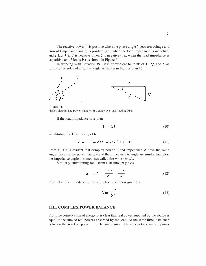
The reactive power Q is positive when the phase angle � between voltage andcurrent (impedance angle) is positive (i.e., when the load impedance is inductive,and I lags V ). Q is negative when � is negative (i.e., when the load impedance iscapacitive and I leads V ) as shown in Figure 6.
In working with Equation (9 ) it is convenient to think of P , Q, and S asforming the sides of a right triangle as shown in Figures 5 and 6.
-���������3
� -.....................................................................................................................................................................................................................................................................................
.............................. ?
VI
P
QS�i �v
��
.
.
.
.
.
.
.
.
.
.
.
.
.
.
.
.
.
.
.
.
.
.
.
.
.
.
.
.
.
.
.
.
.
.
.
.
.
.
.
.
.
.
.
.
.
..
.
.
..
.
..
.
..
..
.....................
.
.
.
.
.
.
.
.
.
.
.
.
.
.
.
.
.
.
.
.
.
.
.
.
.
.
.
.
.
.
.
.
.
.
.
.
.
.
.
.
.
.
.
.
.
.
.
.
.
.
.
.
.
.
.
.
..
.
.
.
.
.
.
.
..
.
.
.
..
.
.
..
.
..
.
..
..
..
....................................
.
.
.
.
.
.
.
.
.
.
.
.
.
.
.
.
.
.
.
.
.
.
.
.
.
.
.
.
.
.
.
.
.
.
.
.
.
.
.
.
FIGURE 6Phasor diagram and power triangle for a capacitive load (leading PF).
If the load impedance is Z then
V = ZI (10)
substituting for V into (9) yields
S = V I� = ZII� = RjIj2 + jXjIj2 (11)
From (11) it is evident that complex power S and impedance Z have the sameangle. Because the power triangle and the impedance triangle are similar triangles,the impedance angle is sometimes called the power angle.
Similarly, substituting for I from (10) into (9) yields
S = V I� =V V �
Z�=jV j2Z�
(12)
From (12), the impedance of the complex power S is given by
Z =jV j2S�
(13)
THE COMPLEX POWER BALANCE
From the conservation of energy, it is clear that real power supplied by the source isequal to the sum of real powers absorbed by the load. At the same time, a balancebetween the reactive power must be maintained. Thus the total complex power
8
����
.
.
.
.
.
.
.
.
.
.
.
.
.
.
.
.
.
.
.
.
.
.
.
.
.
.
.
.
.
.
.
.
.
.
.
.
.
.
.
.
.
.
.
.
.
.
.
.
.
.
.
.
.
.
.
.
.
.
.
.
.
...............................................................................................................................................................................................................
.
.
.
.
.
.
.
.
.
.
.
.
.
.
.
.
.
.
.
.
.
.
.
.
.
.
.
.
.
.
................................................................................................................................................................................................................................................
.
.
.
.
.
.
.
.
.
.
.
.
.
.
.
.
.
.
.
.
.
.
.
.
.
.
.
.
.
.
.
.
.
.
.
.
.
.
.
.
.
.
.
.
.
.
................................
..............................................................................
.
.
.
.
.
.
.
.
.
.
.
.
.
.
.
.
.
.
.
.
.
.
.
.
.
.
.
.
.
.
.
.
.
.
.
.
.
.
.
.
.
.
.
.
.
.
............................................................................................................................................................................
................
.
.
.
.
.
.
.
.
.
.
.
.
.
.
.
..
.
.
.
.
.
.
.
.
.
.
.
.
.
..
.
.
.
.
.
.
.
.
.
.
.
.
.
.
..................................
.
.
.
.
.
.
.
.
.
.
.
.
.
.
..................................
.
.
.
.
.
.
.
.
.
.
.
.
.
.
..
I I1 I2 I3
V Z1 Z2 Z3+�
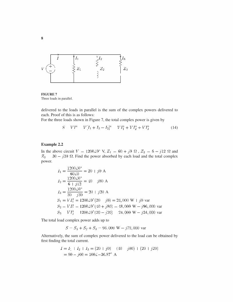
FIGURE 7Three loads in parallel.
delivered to the loads in parallel is the sum of the complex powers delivered toeach. Proof of this is as follows:For the three loads shown in Figure 7, the total complex power is given by
S = V I� = V [I1 + I2 + I3]� = V I�1 + V I�2 + V I�3 (14)
Example 2.2
In the above circuit V = 12006 0Æ V, Z1 = 60 + j0 , Z2 = 6 + j12 andZ3 = 30 � j30 . Find the power absorbed by each load and the total complexpower.
I1 =1200 6 0Æ
606 0= 20 + j0 A
I2 =1200 6 0Æ
6 + j12= 40� j80 A
I3 =1200 6 0Æ
30� j30= 20 + j20 A
S1 = V I�1 = 1200 6 0Æ(20 � j0) = 24; 000 W + j0 var
S2 = V I�2 = 1200 6 0Æ(40 + j80) = 48; 000 W + j96; 000 var
S3 = V I�3 = 1200 6 0Æ(20 � j20) = 24; 000 W � j24; 000 var
The total load complex power adds up to
S = S1 + S2 + S3 = 96; 000 W + j72; 000 var
Alternatively, the sum of complex power delivered to the load can be obtained byfirst finding the total current.
I = I1 + I2 + I3 = (20 + j0) + (40 � j80) + (20 + j20)
= 80� j60 = 100 6 �36:87Æ A

9
and
S = V I� = (1200 6 0Æ)(100 6 36:87Æ) = 120; 000 6 36:87Æ VA
= 96; 000 W + j72; 000 var
A final insight is contained in Figure 8, which shows the current phasor diagramand the complex power vector representation.
.....................................................
................
.
.
.
.
.
.
.
.
.
.
.
.
.
.
.
.
.
.
.
.
.
.
.
.
.
.
.
.
.
.
.
.
.
.
.
.
.
.
.
.
.
.
.
.
.
.
.
.
.
.
..
.
.
.
.
.
.
.
.
.
.
.
.
.
.
.
.
.
.
.
.
.
.
.
.
.
.
.
.
.
.
.
.
.
.
.
.
.
.
.
.
.
.
.
.
.
.
.
.
.
.
.
.
..
.
.
.
.
.
.
.
.
.
.
.
.
.
.
.
.
.
.
.
.
.
.
.
.
.
.
.
.
.
.
.
.
.
.
.
.
.
.
.
.
.
.
.
.
.
.
.
.
.
.
.
..
.
.
..
.
.
..
.
..........
..
.
.
.
.
.
.
.
.
.
.
.
.
.
.
..
.
..
.
..
.
...........................................................
.
..
.............
.
.........................................................................................................................................................................
................
I1
I2
I3
I
............................................................
................
.
.
.
..
.
.
.
.
.
.
.
.
.
.
.
.
.
.
.
.
.
.
.
.
.
.
.
.
.
.
.
.
.
.
.
.
.
.
.
.
.
.
.
.
.
.
.
.
.
.
.
.
.
.
.
.
.
.
.
.
.
.
.
.
.
.
..
.
.
.
.
.
.
.
.
.
.
.
.
.
.
.
.
.
.
.
.
.
.
.
.
.
.
.
.
.
.
.
.
.
.
.
.
.
.
.
.
.
.
.
.
.
.
.
.
.
.
.
.
.
.
.
.
.
.
.
.
.
.
..
.
.
.
.
.
.
.
.
.
.
.
.
.
.
.
.
.
.
.
.
.
.
.
.
.
.
.
.
.
.
.
.
.
.
.
.
.
.
.
.
.
.
.
.
.
.
.
.
.
.
.
.
.
.
.
.
.
.
.
.
..
.
.
.
.
.
.
.
.
.
.
.
.
.
.
.
.
.
.
..
.
..........
.
.............................................................................
................
.........................................................................................................................................................................................................................................
.
...............
S1
S2
S3
S
FIGURE 8Current phasor diagram and power plane diagram.
The complex powers may also be obtained directly from (13)
S1 =jV j2Z�1
=(1200)2
60= 24; 000 W + j 0
S2 =jV j2Z�2
=(1200)2
6� j12= 48; 000 W + j96; 000 var
S3 =jV j2Z�3
=(1200)2
30 + j30= 24; 000 W � j24; 000 var
POWER FACTOR CORRECTION
It can be seen from (6) that the apparent power will be larger than P if the powerfactor is less than 1. Thus the current I that must be supplied will be larger forPF < 1 than it would be for PF = 1, even though the average power P suppliedis the same in either case. A larger current cannot be supplied without additionalcost to the utility company. Thus, it is in the power company’s (and its customer’s)best interest that major loads on the system have power factors as close to 1 as

10
possible. In order to maintain the power factor close to unity, power companiesinstall banks of capacitors throughout the network as needed. They also impose anadditional charge to industrial consumers who operate at low power factors. Sinceindustrial loads are inductive and have low lagging power factors, it is beneficial toinstall capacitors to improve the power factor. This consideration is not importantfor residential and small commercial customers because their power factors areclose to unity.
Example 2.3
Two loads Z1 = 100 + j0 and Z2 = 10 + j20 are connected across a 200-Vrms, 60-Hz source as shown in Figure 9.
(a) Find the total real and reactive power, the power factor at the source, and thetotal current.
����
.
.
.
.
.
.
.
.
.
.
.
.
.
.
.
.
.
.
.
.
.
.
.
.
.
.
.
.
.
.
.
.
.
.
.
.
.
.
.
.
.
.
.
.
.
.
.
.
.
.
.
.
.
.
.
.
.
.
.
.
.
...............................................................................................................................................................................................................
.
.
.
.
.
.
.
.
.
.
.
.
.
.
.
.
.
.
.
.
.
.
.
.
.
.
.
.
.
.
................................................................................................................................................................................................................................................
...............................
...............................
................................
................
.
.
.
.
.
.
.
.
.
.
.
.
.
.
.
..
.
.
.
.
.
.
.
.
.
.
.
.
.
..
.
.
.
.
.
.
.
.
.
.
.
.
.
.
..................................
.
.
.
.
.
.
.
.
.
.
.
.
.
.
..................................
.
.
.
.
.
.
.
.
.
.
.
.
.
.
..
I I1 I2 Ic
200 V 100
10
j20
C+�
....................................................................................................................................
................
.
..
.
..
.
.
..
.
..
.
..
.
..
.
..
.
..
.
..
.
..
.
..
.
..
.
..
.
..
.
..
.
..
.
..
.
..
.
..
.
..
.
..
.
..
.
..
.
..
.
..
.
..
.
..
.
..
.
..
.
..
.
..
.
..
.
..
.
..
.
.
..
.
..
.
..
.
..
.
..
.
..
.
..
.
..
.
..
.
..
.
..
.
..
.
..
.
..
.
..
.
..
.
..
.
..
.
..
.
..
.
..
.
..
.
..
.
..
.
..
.
..
.
..
.
..
.
..
...
.
.
.
.
.
.
.
.
.
.
.
.
.
.
.
..
..
...........
................................................................................................................................................................
................
.
.
.
.
.
.
.
.
.
.
.
.
.
.
.
.
.
.
.
.
.
.
.
.
.
.
.
.
.
.
.
.
.
.
.
.
.
.
.
.
.
.
.
.
.
.
.
.
.
.
.
.
.
.
.
.
.
.
.
.
.
.
.
.
.
.
.
..
.
.
.
.
.
.
.
.
.
.
.
.
.
.
.
.
.
.
.
.
.
.
.
.
.
.
.
.
.
.
.
.
.
.
.
.
.
.
.
.
.
.
.
.
.
.
.
.
.
.
.
.
.
.
.
.
.
.
.
.
.
.
.
.
.
.
.
.
.
.
.
.
.
.
.
.
.
.
.
.
.
.
.
.
.
.
.
.
.
.
.
.
.
.
.
.
.
.
.
.
.
.
.
.
.
.
.
.
.
.
.
.
.
.
.
.
.
..
.
.
.
.
.
.
.
.
.
.
.
.
.
.
.
.
.
.
.
.
.
.
.
.
.
.
.
.
.
.
.
.
.
.
.
.
.
.
.
.
.
.
.
.
.
.
.
.
.
.
.
.
.
.
.
.
.
.
.
.
.
.
.
.
.
.
.
.
.
.
.
.
.
.
.
.
.
.
.
.
.
.
.
.
.
.
.
.
.
.
.
.
.
.
.
.
.
.
..
.
.
.
.
.
.
.
.
.
.
.
.
.
.
.
.
.
.
.
.
.
.
.
.
.
.
.
.
.
.
. Q
Q0
P
Qc
�0........................................
FIGURE 9Circuit for Example 2.3 and the power triangle.
I1 =2006 0Æ
100= 26 0Æ A
I2 =200 6 0Æ
10 + j20= 4� j8 A
S1 = V I�1 = 200 6 0Æ(2� j0) = 400 W + j0 var
S2 = V I�2 = 200 6 0Æ(4 + j8) = 800 W + j1600 var
Total apparent power and current are
S = P + jQ = 1200 + j1600 = 20006 53:13Æ VA
I =S�
V �=
2000 6 �53:13Æ
2006 0Æ= 106 �53:13Æ A
Power factor at the source is
PF = cos(53:13) = 0:6 lagging

11
(b) Find the capacitance of the capacitor connected across the loads to improve theoverall power factor to 0:8 lagging.
Total real power P = 1200 W at the new power factor 0:8 lagging. Therefore
�0 = cos�1(0:8) = 36:87Æ
Q0 = P tan �0 = 1200 tan(36:87Æ) = 900 var
Qc = 1600 � 900 = 700 var
Zc =jV j2S�c
=(200)2
j700= �j57:14
C =106
2�(60)(57:14)= 46:42 �F
The total power and the new current are
S0 = 1200 + j900 = 1500 6 36:87Æ
I 0 =S0�
V �=
15006 �36:87Æ
2006 0Æ= 7:5 6 �36:87Æ
Note the reduction in the supply current from 10 A to 7.5 A.
Example 2.4
Three loads are connected in parallel across a 1400-V rms, 60-Hz single-phasesupply as shown in Figure 10.
Load 1: Inductive load, 125 kVA at 0.28 power factor.
Load 2: Capacitive load, 10 kW and 40 kvar.
Load 3: Resistive load of 15 kW.
(a) Find the total kW, kvar, kVA, and the supply power factor.
An inductive load has a lagging power factor, the capacitive load has a lead-ing power factor, and the resistive load has a unity power factor.
For Load 1:
�1 = cos�1(0:28) = 73:74Æ lagging
The load complex powers are
S1 = 1256 73:74 kVA = 35 kW + j120 kvar

12
����
1400 V 1 2 3
................................
................
.
.
.
.
.
.
.
.
.
.
.
.
.
.
.
..
.
.
.
.
.
.
.
.
.
.
.
.
.
..
.
.
.
.
.
.
.
.
.
.
.
.
.
.
..................................
.
.
.
.
.
.
.
.
.
.
.
.
.
.
..................................
.
.
.
.
.
.
.
.
.
.
.
.
.
.
..
I I1 I2 I3
+�
....................................................................................................................................
................
.
..
.
..
.
..
.
..
.
.
..
.
..
.
..
.
..
.
..
.
..
.
..
.
..
.
..
.
..
.
..
.
..
.
..
.
..
.
..
.
..
.
..
.
..
.
..
.
..
.
..
.
..
.
..
.
..
.
..
.
..
.
..
.
..
.
..
.
..
.
..
.
..
.
.
..
.
..
.
..
.
..
.
..
.
..
.
..
.
..
.
..
.
..
.
..
.
..
.
..
.
..
.
..
.
..
.
..
.
..
.
..
.
..
.
..
.
..
.
..
.
..
.
..
.
..
.
..
...
.
.
.
.
.
.
.
.
.
.
.
.
.
.
.
..
.
............
................................................................................................................................................................
................
.
.
.
.
.
.
.
.
.
.
.
.
.
.
.
.
.
.
.
.
.
.
.
.
.
.
.
.
.
.
.
.
.
.
.
.
.
.
.
.
.
.
.
.
.
.
.
.
.
.
.
.
.
.
.
.
.
.
.
.
.
.
.
.
.
.
.
..
.
.
.
.
.
.
.
.
.
.
.
.
.
.
.
.
.
.
.
.
.
.
.
.
.
.
.
.
.
.
.
.
.
.
.
.
.
.
.
.
.
.
.
.
.
.
.
.
.
.
.
.
.
.
.
.
.
.
.
.
.
.
.
.
.
.
.
.
.
.
.
.
.
.
.
.
.
.
.
.
.
.
.
.
.
.
.
.
.
.
.
.
.
.
.
.
.
.
.
.
.
.
.
.
.
.
.
.
.
.
.
.
.
.
.
.
.
..
.
.
.
.
.
.
.
.
.
.
.
.
.
.
.
.
.
.
.
.
.
.
.
.
.
.
.
.
.
.
.
.
.
.
.
.
.
.
.
.
.
.
.
.
.
.
.
.
.
.
.
.
.
.
.
.
.
.
.
.
.
.
.
.
.
.
.
.
.
.
.
.
.
.
.
.
.
.
.
.
.
.
.
.
.
.
.
.
.
.
.
.
.
.
.
.
.
.
..
.
.
.
.
.
.
.
.
.
.
.
.
.
.
.
.
.
.
.
.
.
.
.
.
.
.
.
.
.
.
. Q
Q0
P
Qc
�0........................................
FIGURE 10Circuit for Example 2.4.
S2 = 10 kW � j40 kvar
S3 = 15 kW + j0 kvar
The total apparent power is
S = P + jQ = S1 + S2 + S3
= (35 + j120) + (10 � j40) + (15 + j0)
= 60 kW + j80 kvar = 1006 53:13 kVA
The total current is
I =S�
V �=
100; 0006 �53:13Æ
1400 6 0Æ= 71:436 �53:13Æ A
The supply power factor is
PF = cos(53:13) = 0:6 lagging
(b) A capacitor of negligible resistance is connected in parallel with the above loadsto improve the power factor to 0:8 lagging. Determine the kvar rating of this ca-pacitor and the capacitance in �F.
Total real power P = 60 kW at the new power factor of 0:8 lagging results in thenew reactive power Q0.
�0 = cos�1(0:8) = 36:87Æ
Q0 = 60 tan(36:87Æ) = 45 kvar
Therefore, the required capacitor kvar is
Qc = 80� 45 = 35 kvar

13
and
Xc =jV j2S�c
=14002
j35; 000= �j56
C =106
2�(60)(56)= 47:37 �F
and the new current is
I 0 =S0�
V �=
60; 000 � j45; 000
14006 0Æ= 53:57 6 �36:87Æ A
Note the reduction in the supply current from 71.43 A to 53.57 A.


![Power System Analysis by Hadi Saadat Electrical Engineering[1]](https://static.fdocuments.in/doc/165x107/55cf94bd550346f57ba41826/power-system-analysis-by-hadi-saadat-electrical-engineering1.jpg)


