Supplementary for Methods of Filling Grease and …...2. Method of applying seal 2.1 Method of...
12
MANUAL NO. HW1483745 Part Number: 182396-1CD Revision: 0 2 Supplementary for Methods of Filling Grease and Applying Seal TYPE: DX200: MS165, MH180, MS210, MH225, MH180-120, MH215 II , MH250 II, MH280 II, ES165RD II, ES200RD II, MH50 II, MH50 II-20, MH50 II-35, MH80 II, MS80E II (NOTE: only for short arm), MS80W II, MS100 II, VS100, MPL80 II, MPL100 II, MA1440, MH12, MA2010, MH24, MA3120, HP20D II DX100: ES165D, ES165D-100, ES200D, ES280D, ES165RD, ES200RD, MH165 , MH165-100, MH200, MH215, MH250, MH50, MH50-20, MH50-35, MH80, MS80E (NOTE: only for short arm), MPL80, MS80W, MS100, MH110, MA3100, HP20D Read this supplemental instruction together with the Instructions and Maintenance Manual. 1 of 12
Transcript of Supplementary for Methods of Filling Grease and …...2. Method of applying seal 2.1 Method of...

MANUAL NO.
HW1483745
Part Number: 182396-1CDRevision: 0
2
Supplementary for Methods of Filling Grease and Applying Seal
TYPE:DX200:MS165, MH180, MS210, MH225, MH180-120, MH215 II , MH250 II, MH280 II, ES165RD II, ES200RD II, MH50 II, MH50 II-20, MH50 II-35, MH80 II, MS80E II (NOTE: only for short arm), MS80W II, MS100 II, VS100, MPL80 II, MPL100 II, MA1440, MH12, MA2010, MH24, MA3120, HP20D IIDX100:ES165D, ES165D-100, ES200D, ES280D, ES165RD, ES200RD, MH165 ,MH165-100, MH200, MH215, MH250, MH50, MH50-20, MH50-35, MH80,MS80E (NOTE: only for short arm), MPL80, MS80W, MS100, MH110, MA3100,HP20D
Read this supplemental instruction together with the Instructions and Maintenance Manual.
1 of 12
182396-1CD
HW1483745
Filling Grease and Applying Seal
Copyright © 2017 Yaskawa America, Inc.
Terms of Use and Copyright Notice
All rights reserved. This manual is freely available as a service to Yaskawa customers to assist in the operation of Motoman robots, related equipment and software This manual is copyrighted property of Yaskawa and may not be sold or redistributed in any way. You are welcome to copy this document to your computer or mobile device for easy access but you may not copy the PDF files to another website, blog, cloud storage site or any other means of storing or distributing online content.
Printed in the United States of America
First Printing, 2017
Yaskawa America, Inc.Motoman Robotics Division100 Automation WayMiamisburg, OH 45342Phone: 937-847-6200
www.motoman.com
2 of 12

HW1483745
Introduction
The chapter 1 "Methods of Filling/Exchanging Grease" of this supplemental instruction shows the
procedures of filling/exchanging the grease of all axes of the robot. Replace the "Grease
Replenishment/ Exchange" in the chapter "Maintenance and Inspection" of the Instructions and
the chapter "Grease Replenishment and Exchange" of the Maintenance Manual for each model
with this supplemental instruction. The chapter 2 "Method of Applying Seal" shows where and
how to apply seal for L- and U-axes. Add this chapter to the chapter "Disassembly and
Reassembly of Speed Reducer" of the Maintenance Manual.
3 of 12
HW1483745
1. Grease Filling
1.1 Notes on Grease Filling Procedures
Make sure to follow the instructions listed below at grease filling or exchange. Failure to observe
the following notes may result in damage to motor and speed reducer.
NOTE
(1) If grease is injected without removing the plug from the grease exhaust port, the grease will
leak inside a motor, or an oil seal of a speed reducer will come off. This may result in a
failure. Make sure to remove the plug. Also, when using a tube, the length should be 150
mm or shorter and the inner diameter should be 6mm or bigger. If the tube is too long, the
exhaust resistance at the tube part is increased, and the inner pressure of the grease bath
is raised. It may result in coming off of an oil seal.
(2) Make sure to use a grease pump to inject grease. Set the grease injection rate at 7 g/s or
less. (Set the air supply pressure to the grease pump at 0.3 MPa or below (as a guide only)).
If not, an oil seal of a speed reducer will come off, and it may result in a failure.
(3) When using extrusion air for discharging the grease, set air supply pressure at 0.025 MPa
or less. If not, an oil seal of a speed reducer will come off, and it may result in a failure.
(4) Make sure to fill the hose on the grease inlet with grease beforehand to prevent air from
leaking into the speed reducer.
(5) After injecting grease, discharge the specified amount of grease. If the discharge is
insufficient, the inner pressure is raised during the operation, and grease may leak. When
discharged too much, the speed reducer is not lubricated sufficiently during the operation,
and it may cause the early failure of the speed reducer.
(6) When filling the grease, the grease may flow out from the grease inlet or the grease exhaust
port. Prepare a container to receive the grease and a waste cloth to wipe the grease in
advance.
(7) After mounting a speed reducer or a motor, leave it for 30 minutes or more and inject grease.
If grease is filled before the sealing bond is hardened, it may cause the grease leakage.
DANGER!
When operating the manipulator, do not enter into the working area of the manipulator. Injury
may result if anyone enter into the working area during operation.
CAUTION!
When using extrusion air for discharging the grease, the grease may be vigorously
discharged from the exhaust port. Perform an operation such as using a tube at the grease
exhaust port to pour into an appropriate container.
4 of 12

HW1483745
1.2 Grease Filling for Speed Reducer
1. Before injecting and discharging the grease, determine the posture of the manipulator. “Fig.1-
1: Recommended Posture of Each Axis While Injecting” is an example of a recommended
posture to take during the grease filling. MOTOMAN-MS210 is shown as an example in the
figure. Remove the plug of inlet and exhaust port. Refer to the ‘Instructions’ and ‘Maintenance
Manual’ of each model for the position of the inlet and exhaust port. In the case when the
manipulator is not able to take a recommended posture due to the external cable and other
peripheral equipment, place an inlet as low as possible, and an exhaust port as high as possible.
This is due to fill-in the grease.
Fig. 1-1: Recommended Posture of Each Axis While Injecting
2. Install the grease zerk to the grease inlet.
3. Inject grease through the grease inlet
– Grease type: Molywhite RE No.00
– Recommended grease lubricator: Powerlube P3C by Macnaught
– Grease injection rate: 7 g/s or less
When the grease is discharged at 2 times/s from the lubricator, set the discharge amount as
5 of 12

HW1483745
3.5 g/time or less. (as a guide only)
– Air supply pressure of grease pump: 0.3 MPa or less (as a guide only)
[Exchanging the speed reducer]
4-A.Stop injection when grease appears from the grease exhaust port.
*Proceed to the step 8 if the axes has no information about the amount of grease to
discharge, referring to the appended table.
[Exchanging the grease]
4-B.The old grease is discharged from the grease exhaust port. At this time, stop injection when
the mixture of the used grease and the new grease in an equal ratio is seen.
*Proceed to the step 7.
*Proceed to the step 8 if the axes has no information about the amount of grease to
discharge, referring to the appended table.
5. Perform the teaching operation for each axis indicated in table 1-1 “Teaching Operation of Each
Axis” approximately 5 times.
Table. 1-1: Teaching Operation of Each Axis
Grease filling point Operation angle at teaching operation Teaching speed
S-axis S-axis ±45°
Arbitrary
L-axis L-axis ±45°
U-axis U-axis ±45°
Casing
RBT-axes
R-axis ±90°
B-axis ±45°
T-axis ±90°
6. Inject the grease again. When the grease is overflowed from the grease exhaust port, injection
is completed.
7. Discharge the specified amount of grease from the grease inlet or exhaust port (for the specified
amount of grease emission, please refer to the attached table "Applicable models and Axes").
In order to exhaust the specified amount of grease, discharge the grease into a container, and
measure it with a weighing scale each time. Use one of the following methods.
Discharge Method 1:A method to extrude the grease by sending air from the grease exhaust
port
- Connect the joint and the hose to the grease inlet.
- Connect the regulator to the grease exhaust port.
- Discharge the grease by sending air from the grease exhaust port. (Extrusion air pressure:
0.025 MPa or below)
- If the grease is not discharged enough by extrusion air from the manipulator, operate the
manipulator again, as shown in table1-1: “ Teaching Operation of Each Axis”.
6 of 12

HW1483745
Discharge Method 2:A method to extrude the grease by sucking the grease from the grease
exhaust port
- Leave the inlet open and insert the tube into the exhaust port.
- Discharge the grease by sucking from the grease exhaust port (Suction pressure:0.025
MPa or below)
- If the grease is not discharged by suction from the manipulator, operate the manipulator
again, as shown in table1-1: “Teaching Operation of Each Axis”.
8. For the point where the grease is filled, perform a playback operation indicated in table 1-2
“Break-in Operation of Each Axis” for break-in the speed reducer with the grease. At this time,
in case the grease is discharged during this operation, remove the grease zerk from the grease
inlet, clean it and degrease the tap part and the thread part of the plug. Apply seal (ThreeBond
1206C) to the thread part of the plug and mount the plug to the grease inlet. Also, in order to
prevent the increase of the inner pressure of the speed reducer, discharge the excess grease
by attaching a bag to collect grease, such as indicated in fig. 1-2 “Grease Receiving Bag (as a
guide only)” , and then perform the break-in operation.
Table. 1-2: Break-in Operation of Each Axis
Grease filling
point
Break-in operation
Operation angle Operation speed Timer after
each operation Operation time
S-axis S-axis ±45°
MOVJ VJ=50.00 1.0s 15 minutes
L-axis L-axis ±45°
U-axis U-axis ±45°
Casing
RBT-axes
R-axis ±90°
B-axis ±45°
T-axis ±90°
9. Wipe the discharged grease using a waste cloth. After cleaning and degreasing the tap part
and the thread part of the plug, apply seal (ThreeBond 1206C) to the thread part of the plug.
Mount the plug to the grease exhaust port, and tighten it with the appropriate tightening torque.
7 of 12

HW1483745
Fig. 1-2: Grease Receiving Bag (as a guide only)
Grease receiving bagCut one corner to remove air. To prevent greasefrom scattering from the cut corner, cover the
receiving bag with a plastic bag etc. without being sealed.
Union (inside dia.: 6mm or more)PT3/8 or PT1/8
Tube (inside dia.: 6mm or more)bond for fixing bag
8 of 12
HW1483745
2. Method of applying seal
2.1 Method of applying seal to the other side of the speed reducer's joint surface
For the applicable model shown in the appendix, “Necessity of applying seal to the other side of
the speed reducer's joint surface” to the model indicated as “Necessary” on the “Necessity of
applying seal” column not only to the speed reducer, but also to the other side of the speed
reducer's joint surface. Figure shows the place of applying seal to the other side of the speed
reducer's joint surface. U-axis of MS210 is shown as an example in the fig. 2-1: “Apply place to
the other side of the speed reducer's joint surface”. When applying the seal, make sure the
“height”, “width”, and “no-gap” fulfill the standard, as shown in the fig. 2-2: “Methods of applying
seal”.
※If grease is filled before the sealing bond is solidified, it may cause the grease leakage. After
tightening the screws, leave it 30 minutes or more, and then fill it with grease.
9 of 12

HW1483745
Fig. 2-1: Place of applying seal to the other side of the speed reducer's joint surface
Fig. 2-2: Methods of applying
10 of 12
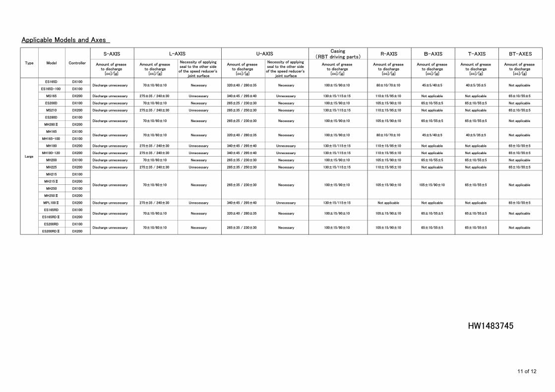
Applicable Models and Axes
S-AXISCasing
(RBT driving parts)R-AXIS B-AXIS T-AXIS BT-AXES
Amount of greaseto discharge
[cc]/[g]
Amount of greaseto discharge
[cc]/[g]
Necessity of applyingseal to the other sideof the speed reducer's
joint surface
Amount of greaseto discharge
[cc]/[g]
Necessity of applyingseal to the other sideof the speed reducer's
joint surface
Amount of greaseto discharge
[cc]/[g]
Amount of greaseto discharge
[cc]/[g]
Amount of greaseto discharge
[cc]/[g]
Amount of greaseto discharge
[cc]/[g]
Amount of greaseto discharge
[cc]/[g]
ES165D DX100
ES165D-100 DX100
MS165 DX200 Discharge unnecessary 275±35 / 240±30 Unnecessary 340±45 / 295±40 Unnecessary 130±15/115±15 110±15/95±10 Not applicable Not applicable 65±10/55±5
ES200D DX100 Discharge unnecessary 70±10/60±10 Necessary 265±25 / 230±30 Necessary 100±15/90±10 105±15/90±10 65±10/55±5 65±10/55±5 Not applicable
MS210 DX200 Discharge unnecessary 275±35 / 240±30 Unnecessary 285±35 / 250±30 Necessary 130±15/115±15 110±15/95±10 Not applicable Not applicable 65±10/55±5
ES280D DX100
MH280Ⅱ DX200
MH165 DX100
MH165-100 DX100
MH180 DX200 Discharge unnecessary 275±35 / 240±30 Unnecessary 340±45 / 295±40 Unnecessary 130±15/115±15 110±15/95±10 Not applicable Not applicable 65±10/55±5
MH180-120 DX200 Discharge unnecessary 275±35 / 240±30 Unnecessary 340±45 / 295±40 Unnecessary 130±15/115±15 110±15/95±10 Not applicable Not applicable 65±10/55±5
MH200 DX100 Discharge unnecessary 70±10/60±10 Necessary 265±35 / 230±30 Necessary 100±15/90±10 105±15/90±10 65±10/55±5 65±10/55±5 Not applicable
MH225 DX200 Discharge unnecessary 275±35 / 240±30 Unnecessary 285±35 / 250±30 Necessary 130±15/115±15 110±15/95±10 Not applicable Not applicable 65±10/55±5
MH215 DX100
MH215Ⅱ DX200
MH250 DX100
MH250Ⅱ DX200
MPL100Ⅱ DX200 Discharge unnecessary 275±35 / 240±30 Unnecessary 340±45 / 295±40 Unnecessary 130±15/115±15 Not applicable Not applicable Not applicable 65±10/55±5
ES165RD DX100
ES165RDⅡ DX200
ES200RD DX100
ES200RDⅡ DX200
HW1483745
Not applicable65±10/55±5105±15/90±10
65±10/55±5
100±15/90±10 65±10/55±5
Discharge unnecessary
Discharge unnecessary
Discharge unnecessary
Discharge unnecessary
Discharge unnecessary
Discharge unnecessary Not applicable65±10/55±5105±15/90±10100±15/90±10
Not applicable105±15/90±10105±15/90±10100±15/90±10
Not applicable45±5/40±580±10/70±10100±15/90±10 40±5/35±5
65±10/55±5
105±15/90±10100±15/90±10
Not applicable45±5/40±580±10/70±10100±15/90±10 40±5/35±5
Not applicable65±10/55±5 65±10/55±5
70±10/60±10 Necessary 265±35 / 230±30 Necessary
70±10/60±10 Necessary 265±35 / 230±30 Necessary
70±10/60±10 Necessary 320±40 / 280±35 Necessary
Necessary
70±10/60±10 Necessary 265±25 / 230±30 Necessary
70±10/60±10 Necessary 320±40 / 280±35 Necessary
L-AXIS U-AXIS
70±10/60±10 Necessary 320±40 / 280±35
Large
Type Model Controller
11 of 12

Applicable Models and Axes
S-AXISCasing
(RBT driving parts)R-AXIS Casing+R-AXIS BT-AXES
Amount of greaseto discharge
[cc]/[g]
Amount of greaseto discharge
[cc]/[g]
Necessity of applyingseal to the other sideof the speed reducer's
joint surface
Amount of greaseto discharge
[cc]/[g]
Necessity of applyingseal to the other sideof the speed reducer's
joint surface
Amount of greaseto discharge
[cc]/[g]
Amount of greaseto discharge
[cc]/[g]
Amount of greaseto discharge
[cc]/[g]
Amount of greaseto discharge
[cc]/[g]
MA3100 DX100
MA3120 DX200
MH50 DX100
MH50Ⅱ DX200
MH50-20 DX100
MH50Ⅱ-20 DX200
MH50-35 DX100
MH50Ⅱ-35 DX200
MH80 DX100
MH80Ⅱ DX200
MPL80 DX100
MPL80Ⅱ DX200
MS80EDX100
MS80EⅡ DX200
MS80W DX100
MS80WⅡ DX200
MS100 DX100
MS100Ⅱ DX200
MH110 DX200
VS100 DX200 Discharge unnecessaryL:300±40 / 260±35E:400±50 / 350±45
L:NecessaryE:Necessary
120±15 / 105±15 Necessary 120±15/105±15 100±15/90±10 Not applicable 60±10/55±5
MA1440 DX200
MH12 DX200
MA2010 DX200
MH24 DX200
HP20DII DX200
HP20D DX100
HW1483745
65±5 / 55±5 Necessary Not applicable Not applicable Not applicable Not applicable
Not applicable
Not applicable
75±10/65±10
55±5/50±5
75±10/65±10
60±10/55±5
675±90/585±75
175±25/155±20
175±25/155±20Not applicable Not applicable
Discharge unnecessary
30±5/25±5
90±10/80±10
Discharge unnecessary
Discharge unnecessary
Discharge unnecessary
100±15/85±10
Not applicable
Not applicableNot applicableNot applicable
Not applicable
Not applicable
Not applicable
Not applicable
Not applicable
100±15/90±10120±15/105±15
Not applicableNot applicable
60±10 / 50±5 Unnecessary 45±5 / 40±5 Unnecessary
25±5 / 20±5 Necessary 20±5 / 15±5 Necessary
100±15 / 90±10 Necessary
220±30/190±25 Necessary 80±10 / 70±10 Necessary
215±30 / 190±25 Necessary 100±15 / 90±10 Necessary
215±30 / 190±25 Necessary 100±15 / 90±10 Necessary
L-AXIS U-AXIS
Small
300±40 / 260±35 Necessary 120±15 / 105±15 Necessary
Medium
Type Model Controller
12 of 12