
Supplemental SEM Procedure for the JEOL JSM6380-LV
13
Supplemental SEM Procedure for the JEOL JSM6380-LV Pages 1 through 3 operating instruction Appendix 1 Pages 4 through 6 - choosing operating parameters Appendix 2 Page 7 Backscatter and Low Vacuum Mode Page 8 Position of z, Aperture, X and Y Wobble correction, and Front Panel Page 9 and 10 Positon of software buttons Page 11 Description of the Manual Adjustment Pad Page 12 Specimen Exchange Window (Sanple Button), Scan rotation Page 13 Proper placement of sample holder on the stage Apr. 13, 20
Transcript of Supplemental SEM Procedure for the JEOL JSM6380-LV

Supplemental SEM Procedure for the JEOL JSM6380-LV
Pages 1 through 3 operating instruction
Appendix 1
Pages 4 through 6 - choosing operating parameters
Appendix 2
Page 7 Backscatter and Low Vacuum Mode
Page 8 Position of z, Aperture, X and Y Wobble correction, and Front Panel
Page 9 and 10 Positon of software buttons
Page 11 Description of the Manual Adjustment Pad
Page 12 Specimen Exchange Window (Sanple Button), Scan rotation
Page 13 Proper placement of sample holder on the stage
Apr. 13, 20

Supplemental Procedure for SEMThis procedure does not replace the hands-on training with the Microscopy Center Manager oran approved representative. Appendix 1 gives you examples Of your Accelerating Voltage,_Spotsize, and Working distance. See Appendix 2 to see examples Of the words that are in boldwithin the instructions.
Machine Setul]1. Turn on the JSM5000* software.2. Turn on IR Camera (to be sure that nothing there is the chamber and that it is clear to
open chamber door.3. Make sure the stage Z is lowered to at least 25 to 30mm as indicated on the right of the Z
stage control.4. Vent the system on front panel -press and hold VENT until the button lights up, it will
flash until the system is vented and then the light will be solid. Or you can click onSample in blue in the software and click on Vent.
5. Open the chamber door by grasping it from the sides and pulling out.6. Mount your sample holder on the stage. Making sure the dovetail on the sample holder
slides firmly onto the mount holder and is pushed on completely to make sure center onthe sample is the same as center on the stage. The large flat side of the sample holdershould be at the top when sliding onto the mount holder. Making sure the sample
holderisoncorrectlyisveryimportantbecausethishelpsground±yoursample.7. Take a picture of your sample at this stage, what your sample looks like to the naked eye
is much different than when looking through the scanning electron microscope. This willhelp you to better visualize where on the sample you are when looking under the electrongun.
8. Check to make sure sample is low enough that it will not make contact with the columnand then push the chamber door closed carefully.
9. While continuing to push gently on the chamber door (this makes sure the vacuumpump dces not pull on room air and backflow oil into the chamber) press the HVACbutton on the front panel until it lights or EVAC on the Sample in blue in the software.Hold the door closed until you hear the pump come on.
10. Let the system pump down for 15 minutes to insure a stal]le environment and betterimaging results
11. Set the accelerator voltage, ACC VOLT, Spotsize, and Aperture according 4pperedit J .Generally you can stan with an Aperture of 2, 5kv, and 35 spotsize
12. Make sure the Magnification is set to the lowest magnification.13. Tun HT on (in the upper left comer). If the image is either too bright or too dark, press
ACB (auto contrast brightness) to make viewing the sample easier.14. Open the Stage Icon in the set of icons on the right in blue. Select sample holder you are
using, generally one of the offerings on the top row. If using the single holder pressSTAGE - INITIAL POSITION - GO to center the saniple. Remember that the imageyou see is rotated 90 degree clockwise in relation to where it was when putting yoursample in the chamber. So the left side of your sample is now at the top when moving thestage.
15. Click on WD in the bottom of your screen towards the left. Select 10mm for yourworking distance. Ideally the working distance is between 8mm and 10mm for the bestresolution and EDAX detection. Selecting 10 mm does not move the stage in the Zdirection, it only sets the lens focal length to 10 mm, you will need to turn the Z knob
E=E
Apr. 13, 20

counter-clockwise to bring the stage up to meet that 10 mm focal length. If at any pointthe image is too bright or dark, select ACE along top of screen, or the two Brightnessand Contrast knobs on the manual adjustment pad,
Prei]aring for lmarfug16. There are seven scan modes but generally only 4 or 5 that are used.
a. Scan 1 is used for focusing your sample. It creates a small window within theImage Display Area that has a real-time imaging. Fine Focus should be done inScan 1 only.
b. Scan 2 is the entire view of the Image Display Area based on yourmagnification. This scan is used to move around on your sample. It should neverbe used for fine Focus.
c. Scan 3 is a 10 second line by line scan of your sample. This will give you a muchcleaner image than Scan 2 but is difficult to move around the sample when usingit. Use Scan 3 to get a better idea how well your image will look beforecommitting to Scan 4 or Photo.
d. Scan 4 and Photo are for taking and saving images. Scan 4 is a line by line scanthat takes 80 seconds and gives a high resolution image. Photo is also a line byline scan but takes 180 seconds and gives and even higher resolution image.
17. Starting in Scan 2, do a coarse Focus on your sample using the right mouse button apdclicking on Focus, keeping Focus and the right mouse button depressed while movingyour mouse up and down until you achieve the best focus. (or use the knob on themanual adjustment pad, Page 11). Look for an area on your sample to do a fine Focus.Look for sman distinct edges to do a fine Focus, soft edges or spheres do not make forgood focal points. Cracks, points, or distinct holes are ideal for fine focus. Once you'vechosen an area double click on it in the Image Display Area to center it. Use coarsefocus to bring the sample into focus. (Coarse Focus can only be done on lowmagnification). Once you have chosen the object to focus on click on Scan 1 and bringyour magnification up as high as you can while still being able to see the object you aretrying to focus on. Ideally you will focus at 15 times the magnification you will beimagingat.NowyouwillclickonFocususingtheleftmousebuttonandkeepingthemouse button depressed while you move the mouse up and down to find the best focus.Note: especially during fine focus, if the focus becomes better when moving in onedirectionbutyouhitthelimitoffocusinthatdirection.LetgoofthemousebuttonattheedgeofthewindowandthenclickonFocuswiththeleftmousebuttonagainandcontinue movement in that direction until your focus improves.
a. If this is the first sample you have done or if you changed the aperture you mustdo a Wobble, Stigma X and Stigma Y to get the best focus. Woad/e Sfeoald onlybeattemptedby;omeonewhohasbeentraine4,ask for.Eel.pfr_o.y.them.I!:r?s`c.opycenterwianag6rorapprovedrepresentativeifyoune.e_4feelp.C+ice?Twth.H`hethe image should appear to be breathing in and out, if it is moving side to side orup and down you will need to adjust the Xrdirection fine adjustment knob and theY-direction fine adjustment knob to stop the movement. These fine adjustmentknobs are located on the colunm along with the Aperture selection knob. Themovements on the X & Y-fine adjustment knobs are very minor movements. Ifyou move these knobs too much you will lose the aperture hole and theMicroscopyCenterManagerorarepresentativewillneedtobecalledtofixit.
Apr. 13, 20

Once you have stopped the x and y movement press Wobble agaln to close thewindow. Then immediately press Lens Reset.
b. Now that the stigma has been corrected mechanically you will now need to refineit electronically. If your sample is really out of focus from the Lens Resetprocess, you can do a coarse focus followed by a fine focus. Once you havecompleted the fine Focus you will use the same procedure on the Stigma X asyou do when doing Focus, pressing the left mouse button while clicking on eitherStigma X or Stigma Y. Once the image is as good as you can get it do the Focusone more time. This should be performed in Scan 1.
18. Capturing the Imagea. Consistency is key for research and deciding the magnification(s) in which you
will taking images is crucial. Standard suggestion is to take a low magnificationimage, an intermediate magnification and a high magnification. Of course you candecide how many images and at what magnifications are important for yourresearch.
b. Frame your image as you would like to save it. Move the stage so that the objectyou want to image is centered horizontally and up slightly vertically (this is tomake room for the image information on the bottom). Press Scan 4 or Photo totake the image. When the scan is complete the screen will freeze and the scarminginformation will be on the bottom of the image display screen. This will display
the image, the number of images (if set up to record), the working distance, thespotsize, secondary electron (other option is backscatter).
19. To finish, turn HT OFF (top left comer).20. Lower Z to 25 or greater.21. Wait 10 minutes for the chamber to cool before opening the chamber, introducing cold
alr immediately can cause condensation on the chanber.
Other ueful itemsBackscatter - See page 7Low Vacuum Mode - See page 7Sscan Rotation - See page 1 1
Apr. 13, 20

Appendix 1
Choosing Operating setup1 . Choose the correct aperture on the column for the sample you are working with. Note the
beam at higher kv damages the aperture so for Apertures 1 and 2 use 10kv or lower.a. Aperture 1 is 20pr which gives higher resolution and a greater depth of field but
can give you a much grainier image.b. Aperture 2 is 30H and decreases the resolution and depth of field slightly. This is
the most used aperture on the machine. Use this aperture if your image usingAperture 1 is too grainy.
c. Aperture 3 is loon and is used for using higher kv or EDS x-ray analysis. Thedisadvantages of the higher kv are; unclear surface structures, sample damage,increased charge-up, and more edge effect.
2. Selecting the kv and spotsize is more sul)jective and here are a few general suggestions.When working with samples that are easily damaged by the ion bean it is suggested thatyou start with 5 kv and a spotsize of 30. For metals and samples that are less affected bythe ion beam you can start with 10 kv or higher and again, start at a spotsize of 30.
a. Exam the JEOI, Operating Manual for accelerating voltage - When you use alower accelerating voltage, the details of microscopic structure of the specimensurface appear more clearly. When using a high accelerating voltage, theilluminating electrous can reach deeper inside the specimen and as a resulturmecessary signals generated from the inside of the specimen @ackscatteredelectrous, for example) lower the contrast, thus hiding the details of microscopicstructure of the specimen surface. For this reason, especially for observing aspecimen of lowrdeusity material, a low accelerating voltage is desirable.
b. EELm_ the JEOL Operating Man_ua± for spotsize - As the electron probe diameter(the spotsize) becomes smaller, higher magnification ad so higher resolution areobtalned. However, image smoothness, that is, the SIN (signal/noise) ratio of theimage, depends on the illunirating current. When you try to reduce the probediameter, the probe current reduces as a result. Therefore, an appropriateilluminating current must be selected according to magnification, observationconditions (including accelerating voltage, tilting of specimen and others) and thespecimen itself.
Apr. 13, 20

Apr. 13, 20

Appendix 2BackscatterBackscatter electrous differs from secondary electrous due to the high number of secondaryelectrous verses the lower number of backscatter electrous. For this reason the beam current forbackscatter should be 5 to 10 times greater to insure adequate signal-to-noise ratio. Whenscanning using secondary electrous all electrous are shown equally, for this reason the image hasgreater resolution. When imaging in backscatter the lighter the element the darker it appears andthe heavier the element the lighter it appears. This is because the heavier the element the morebackscatter it produees. Multilayer metals with oxidation are good candidates for backscatterbecause it essentially reduces the washout of the image caused by the oxygen.Vthen using backscatter:
• The average working distance should be between 10 mm and 20 mm.• The spotsize should be between 30 and 60.• You shoulduse aperture 2 or 3.• Turn off the IR camera. The backscatter will not work if the in camera is on.• The signal shouldbe setto BEI
There are 3 modes of backscatter, Compo, Topo, and Shadow. Please get with the MicroscopyCenter Manager or approved representative to determine which mnde is best for your sample.Any time you switch to backscatter or within backscatter modes you must press ACB.
Low VacuumLow Vacuum is best when used on samples that cannot be coated or cannot withstand the highvacuum environment. The machine is capable of running in a vacuum of 10 to 130 Pa, this lowvacuum has a poor signal-to-noise ratio making inaging difficult and is suited to magnificationlower than 3000x. Low vacuum assists in eliminating the effects of charge accumulation on thesurface and to preserve fragile structures. Low Vacuum imaging is done using the backscattershadow mode @EIW).
• Set the accelerating voltage to l5kv.• Biological specimen -pressure 50 to 70 Pa, spotsize 30-60.• Dry paper, cloth, resin, etc. -pressure 20 to 30 Pa, spotsize 30 to 40.
Apr. 13, 20

Apr. 13, 20

1 - HT On/Off2 - Scan 13 - Scan 24 - Scan 35 - Scan 46 - Photo7 - Auto Contrast/Brightness8 - Wobbler9 - Lens F3eset10 - Stage1 1 - Sample12 -Magnification13 - AccelerationVoltage14 - WorkingDistance1 5 - Spot Size16 -Signal17 - Vacuum Mode18 -lR Camera19 -Image DisplayArea
Apr. 13, 20
1416

20 - Contrast21 - Brightness22 - Focus23 - Stigma X24 - Stigma Y
Apr. 13, 20
Fill E.-.I,,i {t,`,£q.zv Tools fr.9.tMao S.hp mb
e:OVtr ' fro'
a;aSun gut £;,F±
rmjtl
ill i II i E ( E i RE

Many of the things you can do in the software can be done using the Manual Adjustment Pad. Several of the knobs and the joystick canhave different functions based on the selection of the following buttons. When the Course button is lit, the knob below it is in course focus, ifit is not lit, the knob functions as a fine focus. While the course focus should only be turned a limited amount, on fine focus the knob must betuned many times one direction or the other to see a difference. When the STIG button is unlit the knobs to the left are used for manualcontrast and brightness, when the STIG button is lit then the knobs function as Stigma X and Stigma Y. If fine shift is lit then the joystick willonly move the stage a finite amount. If instead you select the X/Y button the joystick can move the stage to its maximum allowed distance.The T/Z and R buttons are not available functions on this system.
3
Apr. 13, 20
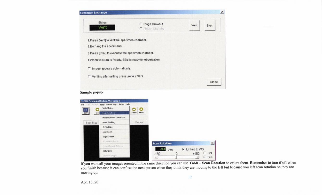
Status11- ¢ Stage Drawtlutr >ti,.i i i i, i i ,.I. j±i ,± I f! L`j `± i
1.Pre§§ prenq to ventthe specimen Chamber.
2.EHchang the Specimens.
3,Press |Evac] to evacuate the specimen chamber.
4.When vacuum ls F3eady, SEM is ready for observation.
r Image appBars automatically.
r VBnting after setting pressure to 270Pa.
Sample popup
Fie F,i,-,: Lrt'i.-Jr2.3 r+~de-Preset Mag Setap Help
I deg. PLinkedtowD-180 a +leo r oNrfey tr':...'i_.:.::,:&Ti-:J^.-+':=.`A.:.-'x.-,::',.`:i`ng~*:.ul S OFF
Tools - Scan Rotation to orient them. Remember to turn if off whenyoufinishbecahseitcan-confusethenextpersonwhentheythinktheyaremovingtotheleftbutbecauseyouleftscanrotationontheyaremoving up.
If you want all your images oriented in the same direction you can use
Apr. 13, 20

Dovetail on bottom of sample holders Stage tuned for image to show how dovetail fits onto the stage.
Stage inside the SEM, the dovetail must be placed on the circular holder and the flat of the sample holderpushed toward the flat on the stage.
Apr. 13, 20


![USER GUIDE – JEOL JSM-6300 SCANNING ELECTRON … ELECT… · of the JEOL operating manual.] When evacuation is completed and the column reaches the pressure required for high-voltage](https://static.fdocuments.in/doc/165x107/5a7945157f8b9ae93a8c80b0/user-guide-jeol-jsm-6300-scanning-electron-electof-the-jeol-operating.jpg)