
Supplemental manual delta DLTa and Sigma SxCb with...
22
delta ® DLTa and Sigma SxCb with PROFIBUS ® Supplemental manual Pro M i n e n t o This operating manual is only valid in conjunction with the "Operating manual: delta ® solenoid metering pump with opto‐ Drive ® DLTa regulated solenoid drive" or "Operating manual: Sigma/ x control type SxCb motor metering pump"! The operator shall be liable for damage caused by errors during installation and operation! Part no.985399 BA DE 027 10/12 EN Please carefully read these operating instructions before use! · Do not discard! The operator shall be liable for any damage caused by installation or operating errors! Technical changes reserved.
Transcript of Supplemental manual delta DLTa and Sigma SxCb with...

delta® DLTa and Sigma SxCbwith PROFIBUS®
Supplemental manual
ProM
ine n
t
o
This operating manual is only valid in conjunction with the "Operating manual: delta® solenoid metering pump with opto‐Drive® DLTa regulated solenoid drive" or "Operating manual: Sigma/ x control type SxCb motor metering pump"!The operator shall be liable for damage caused by errors during installation and operation!
Part no.985399 BA DE 027 10/12 EN
Please carefully read these operating instructions before use! · Do not discard!The operator shall be liable for any damage caused by installation or operating errors!
Technical changes reserved.

985400, 1, en_GB
© 2008
ProMinent Dosiertechnik GmbHIm Schuhmachergewann 5-1169123 HeidelbergGermanyTelephone: +49 6221 842-0Fax: +49 6221 842-617email: [email protected]: www.prominent.com
2
Table of contents1 Prerequisites.................................................................................... 4
2 Setting up the pump........................................................................ 52.1 General information................................................................. 52.2 Setting a slave address........................................................... 52.3 Activating / deactivating the PROFIBUS®............................... 5
3 Particular features of PROFIBUS® mode........................................ 63.1 General information................................................................. 63.2 Displays and indicators........................................................... 63.3 LEDs on the PROFIBUS® module.......................................... 63.4 Using the metering monitor..................................................... 7
4 Installation....................................................................................... 8
5 Operation....................................................................................... 105.1 General information............................................................... 105.2 GSD file................................................................................. 105.3 Description of the data objects.............................................. 105.4 Cyclical data traffic................................................................ 145.4.1 Overview of the data objects.............................................. 145.4.2 Configuration...................................................................... 175.5 Acyclical data traffic.............................................................. 205.6 Extended diagnostic.............................................................. 21
Table of contents
3

1 Prerequisites
The pump can be expanded to include PROFIBUS® functionality using aplug-in module. Plug the plug-in module into the front of the pump (thesame way as with a relay module). The menu item "PROFIBUS®" will thenappear in the operating menu.
The pump must have at least software version V01.03.06.00(delta® DLTa) or V01.01.00.00 (Sigma Control SxCb) andhardware version V01.04.00.00 for the delta®, for the PRO‐FIBUS® module to work. If it does not work, the LED on thePROFIBUS® module slowly flashes red and green.
Prerequisites
4

2 Setting up the pump
2.1 General information
The pump with the PROFIBUS® module plugged in is set up in the sameway as the standard pump; it just includes the bus functionality.
If there is no activity for longer than 60 sec., the setupprocess is cancelled.
2.2 Setting a slave address
The default address is "125". If a master in the PROFIBUS® section issuesthe slave addresses, then setting the slave address manually is not neces‐sary.
1. Press the [P] button for 2 seconds.
2. delta® only: Move to ‘Settings’ with the [arrow buttons] and pressthe [P] button.
3. Move to ‘PROFIBUS®’ with the [arrow buttons] and press the [P]button.
4. Move to ‘Address’ with the [arrow buttons] and press the [P] button.
Always use three digits for the PROFIBUS® address (addresses from"002" to "125"):
1. Set the first digit with the [Down] button and press the [P] button.
2. Set the second digit with the [Down] button and press the [P] button.
3. Set the third digit with the [arrow buttons] and press the [P] button.
2.3 Activating / deactivating the PROFIBUS®
So that the pump can be controlled via the PROFIBUS®, ‘PROFIBUS®’must be set to ‘Active’ in the operating menu:
1. Press the [P] button for 2 seconds.
2. With the [arrow buttons] move to ‘PROFIBUS®’ and press the [P]button.
3. With the [arrow buttons] move to ‘Active’ or ‘Inactive’ and press the[P] button. You're done!
Even while the PROFIBUS® is ‘Active’ , all the external inputs such aslevel monitor, metering monitor and external control (pause, contact input,analogue input) still work. They produce the anticipated reactions, just as ifthe pump was being operated without the PROFIBUS® module plugged in- see the pump operating manual. The pump transmits relevant informa‐tion over the PROFIBUS® to the master (PLC, PC, etc.).
If the PROFIBUS® is set to ‘Inactive’ , the settings of the previouslyselected operating mode are reloaded.
If the pump is switched to another operating mode, then it stops and canonly be started via the [Stop/Start] button.
Setting up the pump
5
3 Particular features of PROFIBUS® mode
3.1 General information
In PROFIBUS® mode, the pump cannot be manuallyadjusted or programmed! To do so, switch the PROFIBUS®
to ‘Inactive’ .
n Using the [ i ] button, you can switch between the permanent displaysat any time, as in the other operating modes. This has no influenceupon the operation of the pump.
n When switching to PROFIBUS® mode, the settings are carried overfrom other operating modes. Settings made via the PROFIBUS®, onthe other hand, are not saved! They are only valid while the pump isconnected to the PROFIBUS®. Only the total number of strokes andtotal litres figures are continuous (saved).
n If the pump is switched to PROFIBUS® mode, then it stops and canonly be started via the PROFIBUS®.
3.2 Displays and indicators
During PROFIBUS® mode, the operation indicator contains additional sym‐bols.
Commonly used symbols can be found in the chapter "Con‐trol elements“ in the "Operating manual: delta® solenoidmetering pump with controlled optoDrive® solenoid drive" orthe "Operating manual: Sigma/ x control type SxCb motormetering pump".
Stop PROFIBUS®: the pump was stopped via the PROFIBUS®. Themaster transmits an appropriate telegram to the pump.
Connection error: if the pump loses its connection to the PROFIBUS®
(e.g. when the PROFIBUS® is stopped), then the error symbol appearsand the symbol flashes in the main indicator.
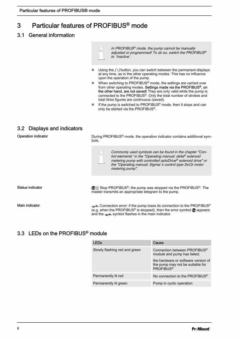
3.3 LEDs on the PROFIBUS® module
LEDs Cause
Slowly flashing red and green Connection between PROFIBUS®
module and pump has failed;
the hardware or software version ofthe pump may not be suitable forPROFIBUS®
Permanently lit red No connection to the PROFIBUS®
Permanently lit green Pump in cyclic operation
Operation indicator
Status indicator
Main indicator
Particular features of PROFIBUS® mode
6

3.4 Using the metering monitor
To use the metering monitor during PROFIBUS® mode, the "Meteringmonitor" socket must be connected. The pump then transmits ‘Present’for the "Flow" status bit. The metering monitor can be switched on and offwith the PROFIBUS® using the ‘Flow monitoring’ parameter - see Ä ‘Dataon the pump’ Table on page 15.
Particular features of PROFIBUS® mode
7

4 Installation
All bus subscribers must be connected in series. Up to 32 stations arepossible (masters, slaves, repeaters).
At both the start and end of the cabling, the bus must be connected with aterminating resistor.
For the PROFIBUS® cables, use cables which are shielded, twisted, andhave two-cores (twisted pair), in accordance with EN 50170 (cable type A).
Earthing the shield at one end prevents low-frequency earthloops. Earthing the shield at one end has no effect on HFmagnetic interference. Earthing the shield at both ends andthe twisted pair do indeed affect the HF magnetic interfer‐ence, though it has no effect upon HF electrical interference.
It is recommended to establish on the PROFIBUS® a low-inductance (i.e.wide area and low resistance) connection to the protective earth on bothsides.
The total length of the bus cabling without repeaters will vary dependingon the desired transfer speed:
Transfer speed and length of the bus cabling
Transfer speed Max. length of the bus cabling
kBit/s m
1500 200
500 400
187.5 1000
93.75 1200
19.2 1200
9.6 1200
The PROFIBUS® module has an M12 industrial socket for connecting to aPROFIBUS® cable. The pin allocation corresponds to the PROFIBUS®
standard - see below - meaning that commercially available bus connec‐tors can be used. Please note that cable connections with these connec‐tors generally only comply with a contact and humidity protectionaccording to IP 20!
An installation compliant with contact and humidity protection according toIP 65 is possible, as the M12 industrial socket on the PROFIBUS® moduleallows for this. However, the PROFIBUS® cable must then be equippedwith M12 industrial connectors according to IP 65.
In order to achieve protection class IP 65 for the PROFIBUS® cable instal‐lation, special Y-adapters or termination adapters must be used (e.g. - seebelow).
Bus installation
Connectors and cables
Information on achieving protection classIP 65
Installation
8
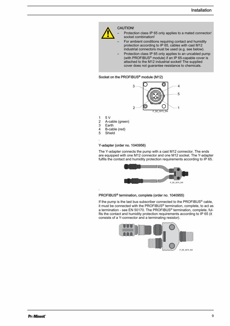
CAUTION!– Protection class IP 65 only applies to a mated connector/
socket combination!– For ambient conditions requiring contact and humidity
protection according to IP 65, cables with cast M12industrial connectors must be used (e.g. see below).
– Protection class IP 65 only applies to an uncabled pump(with PROFIBUS® module) if an IP 65-capable cover isattached to the M12 industrial socket! The suppliedcover does not guarantee resistance to chemicals.
Socket on the PROFIBUS® module (M12)
P_DE_0073_SW1
5
43
2
1 5 V2 A-cable (green)3 Earth4 B-cable (red)5 Shield
.
Y-adapter (order no. 1040956)
The Y-adapter connects the pump with a cast M12 connector. The endsare equipped with one M12 connector and one M12 socket. The Y-adapterfulfils the contact and humidity protection requirements according to IP 65.
P_DE_0074_SW
.
PROFIBUS® termination, complete (order no. 1040955)
If the pump is the last bus subscriber connected to the PROFIBUS® cable,it must be connected with the PROFIBUS® termination, complete, to act asa termination - see EN 50170. The PROFIBUS® termination, complete, ful‐fils the contact and humidity protection requirements according to IP 65 (itconsists of a Y-connector and a terminating resistor).
P_DE_0075_SW
Installation
9
5 Operation
5.1 General information
With the PROFIBUS® module plugged in, the pump represents a sub‐scriber with slave functionality in the PROFIBUS®, according to DP-V1.Usage data is then transferred both cyclically and acyclically.
5.2 GSD file
The GSD file must be used to configure the masters. It describes all fea‐tures of the pump in PROFIBUS® mode (keywords, diagnostics, modules,slots). The GSD file can be downloaded from the PROFIBUS® website andfrom the ProMinent website. The file name is unique: PROM0B02.GSD
5.3 Description of the data objects
So that the pump can join the cyclic data traffic, the initialparameters must be transferred from the master. This onlyrequires the default parameter settings - there are no appli‐cation parameters.
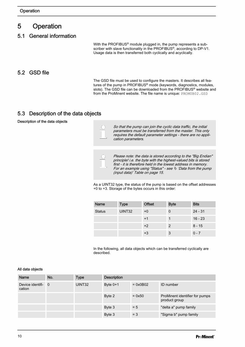
Please note: the data is stored according to the "Big Endian"principle! i.e. the byte with the highest-valued bits is storedfirst - it is therefore held in the lowest address in memory.For an example using "Status" - see Ä ‘Data from the pump(input data)’ Table on page 15.
As a UINT32 type, the status of the pump is based on the offset addresses+0 to +3. Storage of the bytes occurs in this order:
Name Type Offset Byte Bits
Status UINT32 +0 0 24 - 31
+1 1 16 - 23
+2 2 8 - 15
+3 3 0 - 7
In the following, all data objects which can be transferred cyclically aredescribed.
All data objects
Name No. Type Description
Device identifi‐cation
0 UINT32 Byte 0+1 = 0x0B02 ID number
Byte 2 = 0x50 ProMinent identifier for pumpsproduct group
Byte 3 = 5 "delta a" pump family
Byte 3 = 3 "Sigma b" pump family
Description of the data objects
Operation
10

Name No. Type Description
Status 1 UINT32 Bit Name Function
0 System 00 – Init 03 –Test
1 01 – Ready 04 - First run
2 02 – Diagnose 05 - Power‐down
3 Mode 00 – halt 03 –contact
4 01 – manual 04 - analog
5 02 – batch
6 Error There are errors - see "Errors"
7 Warnings There are warnings - see"Warnings"
8 Stop Pump is stopped
9 Intake Pump is in intake mode (higher-level function)
10 Auxiliary Pump is in auxiliary mode(higher-level function)
11 Pause Pump is switched to pause(higher-level function)
12 Module Automatic mode
13 Flow Metering monitor activated
14 Batch mem. Batch memory is activated
15 Calibrated Pump is calibrated
16 Relay 1 Relay 1 is physically present
17 Relay 2 Relay 2 is physically present
18 AnalogOut Module is physically present
19 Diaphragmbreak
Diaphragm break option isinstalled
20 Concentration Concentration calculation is acti‐vated (delta® only)
21 - -
22 - -
23 Airlock Drive controller signals air in themetering head (delta® only)
24 Excessivepressure
Drive controller signals “exces‐sive counter pressure”
25 Depressurised Drive controller signals "nocounter pressure" (delta® only)
26 Bleeding Pump is being bled (delta® only)
27 - Always true
28 Direct mode Pump functioning in direct mode(limited range of functionality)(delta® only)
Start/Stop 2 BYTE Corresponds with the Start/Stop switch; if Start/Stop = 0 then thepump is stopped.
Operation
11

Name No. Type Description
Reset 3 BYTE If the value of "Reset" switches from 1 to 0, the internal pumpmemory is reset (e.g. for batch metering) and - where possible -any pending errors are reset.
Mode 4, 5 BYTE Value Name Description
0 Halt Pump is ready but not metering.
1 Manual Pump is metering continuouslyat the set frequency.
2 Charge When triggered, pump ismetering the number of strokesset under Batch preselection.
3 Kontakt Pump is metering the number ofstrokes calculated from theproduct of "Number of triggeringpoints * External factor".
4 Analog Pump is metering in accordancewith the analogue signal and theoperating mode ‘Analogue’ seton the pump.
Frequency 6, 7 UINT16 Set metering frequency in strokes / hour (0 - "Maximum fre‐quency").
Actual fre‐quency
8 UINT16 Actual metering frequency in strokes / hour (0 - 'Maximum fre‐quency').
Maximum fre‐quency
9 UINT16 Maximum metering frequency in strokes / hour (0 - 12,000). Basedon which metering mode is set, the max. frequency can be sub‐stantially less than in normal mode.
Batch prese‐lection
10, 11 UINT32 Number of strokes in batch operation per triggering. (0…99999).
Batch start 12 BYTE If the value changes from 1 to 0, batch metering is triggered inbatch mode. Batches can also be triggered via the contact input.
Batch memory 13 BYTE If the batch memory is activated and a new batch is triggered whilebatch metering is already ongoing, then the remaining strokes isincreased by the number of the new batch.
If the memory is not activated, the remaining strokes for the incom‐plete batch are deleted and the new batch is processed.
Remainingstrokes
14 UINT32 The number of strokes still to be processed for a batch
External factor 15, 16 UINT16 Factor by which the incoming pulses are multiplied. The factor isprovided in hundredths. The value range is 1 - 9999 - the factor isthen 0.01 - 99.99.
Externalmemory
17 BYTE As is the case for batch metering, the value is also added in thiscase for high factors, or the remaining strokes are deleted.
Stroke length 18 BYTE Set stroke length on the pump ( 0 - 100%)
Metering mon‐itor
19 BYTE If the metering monitor is installed, it can be switched on (1). (0) isfor switching it off.
Concentration 20 FLOAT If calculation of the concentration is activated on the pump, the cur‐rent concentration can be viewed here (delta® only).
Error 21 UINT16 Bit Name Function
0 Minimum Level of metered liquid too low
1 Batch Too many metering strokes >100,000
2 Analogue current is less than 4mA
Operation
12

Name No. Type Description
3 Analogue >23mA
Analogue current is higher than23 mA
4 Metering mon‐itor
Fault on metering monitor
5 Diaphragmbreak
Diaphragm in metering headdefective
6 Airlock Air in the metering head (delta®
only)
7 Excessivepressure
Excessive pressure in thehydraulic system
8 - -
9 - -
10 Low pressure Pressure in the hydraulicsystem is too low (delta® only)
11 Stroke lengthchanged
The stroke length has beenchanged in a locked state
12 Bleeding Automatic bleeding not possible(delta® only)
13 Bus error Bus error signalled by themodule
14 System error System components defective -see LCD screen
15 Module error Error in the module handling
Warnings 22 UINT16 Bit Name Function
0 Minimum Level of metered liquid too low
1 Calibration Set stroke length out of calibra‐tion tolerance
2 Metering mon‐itor
Fault on metering monitor
3 Diaphragmbreak
Diaphragm in metering headdefective
4 Airlock Air in the metering head
5 - -
6 - -
7 Excessivepressure
Excessive pressure in thehydraulic system
8 Low pressure Insufficient pressure in thehydraulic system
Stroke counter 23 UINT32 Counts the number of strokes since the last reset
Reset strokecounter
24 BYTE If the value changes from 1 to 0, the stroke counter is reset.
Quantitycounter
25 FLOAT Counts the metering output in litres since the last reset
Litres perstroke
26 FLOAT Litres per stroke. Depends on the frequency and the stroke lengthsetting
Reset quantitycounter
27 BYTE If the value changes from 1 to 0, the quantity counter is reset
ID code 28 STRING Pump ID code (pump specification)
Operation
13
Name No. Type Description
Serial number 29 STRING Pump serial number
Name 30 STRING Pump name, freely-definable (max. 32 characters)
Installation site 31 STRING Installation site, freely-definable (max. 32 characters)
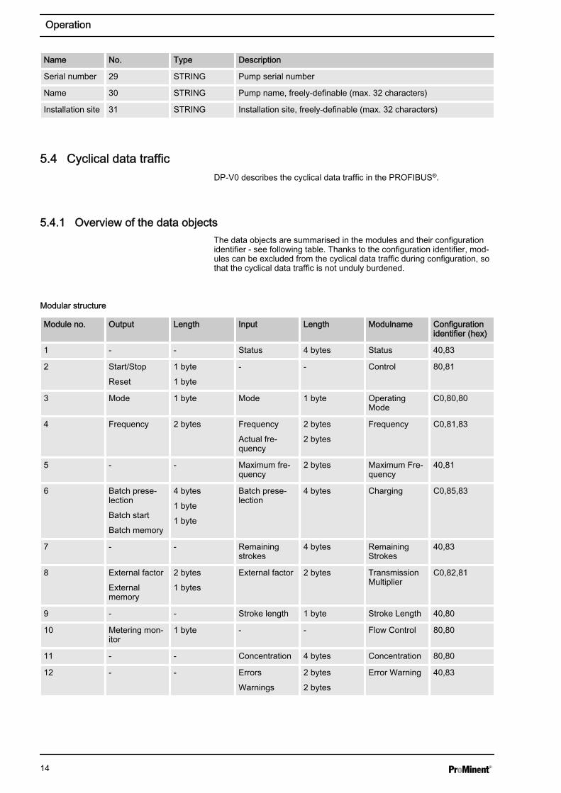
5.4 Cyclical data traffic
DP-V0 describes the cyclical data traffic in the PROFIBUS®.
5.4.1 Overview of the data objects
The data objects are summarised in the modules and their configurationidentifier - see following table. Thanks to the configuration identifier, mod‐ules can be excluded from the cyclical data traffic during configuration, sothat the cyclical data traffic is not unduly burdened.
Modular structure
Module no. Output Length Input Length Modulname Configurationidentifier (hex)
1 - - Status 4 bytes Status 40,83
2 Start/Stop
Reset
1 byte
1 byte
- - Control 80,81
3 Mode 1 byte Mode 1 byte OperatingMode
C0,80,80
4 Frequency 2 bytes Frequency
Actual fre‐quency
2 bytes
2 bytes
Frequency C0,81,83
5 - - Maximum fre‐quency
2 bytes Maximum Fre‐quency
40,81
6 Batch prese‐lection
Batch start
Batch memory
4 bytes
1 byte
1 byte
Batch prese‐lection
4 bytes Charging C0,85,83
7 - - Remainingstrokes
4 bytes RemainingStrokes
40,83
8 External factor
Externalmemory
2 bytes
1 bytes
External factor 2 bytes TransmissionMultiplier
C0,82,81
9 - - Stroke length 1 byte Stroke Length 40,80
10 Metering mon‐itor
1 byte - - Flow Control 80,80
11 - - Concentration 4 bytes Concentration 80,80
12 - - Errors
Warnings
2 bytes
2 bytes
Error Warning 40,83
Operation
14
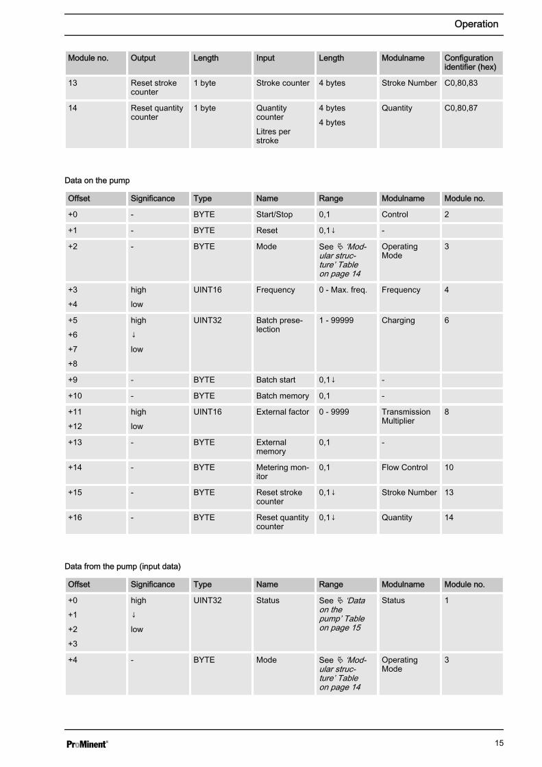
Module no. Output Length Input Length Modulname Configurationidentifier (hex)
13 Reset strokecounter
1 byte Stroke counter 4 bytes Stroke Number C0,80,83
14 Reset quantitycounter
1 byte Quantitycounter
Litres perstroke
4 bytes
4 bytes
Quantity C0,80,87
Data on the pump
Offset Significance Type Name Range Modulname Module no.
+0 - BYTE Start/Stop 0,1 Control 2
+1 - BYTE Reset 0,1↓ -
+2 - BYTE Mode See Ä ‘Mod‐ular struc‐ture’ Tableon page 14
OperatingMode
3
+3
+4
high
low
UINT16 Frequency 0 - Max. freq. Frequency 4
+5
+6
+7
+8
high
↓
low
UINT32 Batch prese‐lection
1 - 99999 Charging 6
+9 - BYTE Batch start 0,1↓ -
+10 - BYTE Batch memory 0,1 -
+11
+12
high
low
UINT16 External factor 0 - 9999 TransmissionMultiplier
8
+13 - BYTE Externalmemory
0,1 -
+14 - BYTE Metering mon‐itor
0,1 Flow Control 10
+15 - BYTE Reset strokecounter
0,1↓ Stroke Number 13
+16 - BYTE Reset quantitycounter
0,1↓ Quantity 14
Data from the pump (input data)
Offset Significance Type Name Range Modulname Module no.
+0
+1
+2
+3
high
↓
low
UINT32 Status See Ä ‘Dataon thepump’ Tableon page 15
Status 1
+4 - BYTE Mode See Ä ‘Mod‐ular struc‐ture’ Tableon page 14
OperatingMode
3
Operation
15
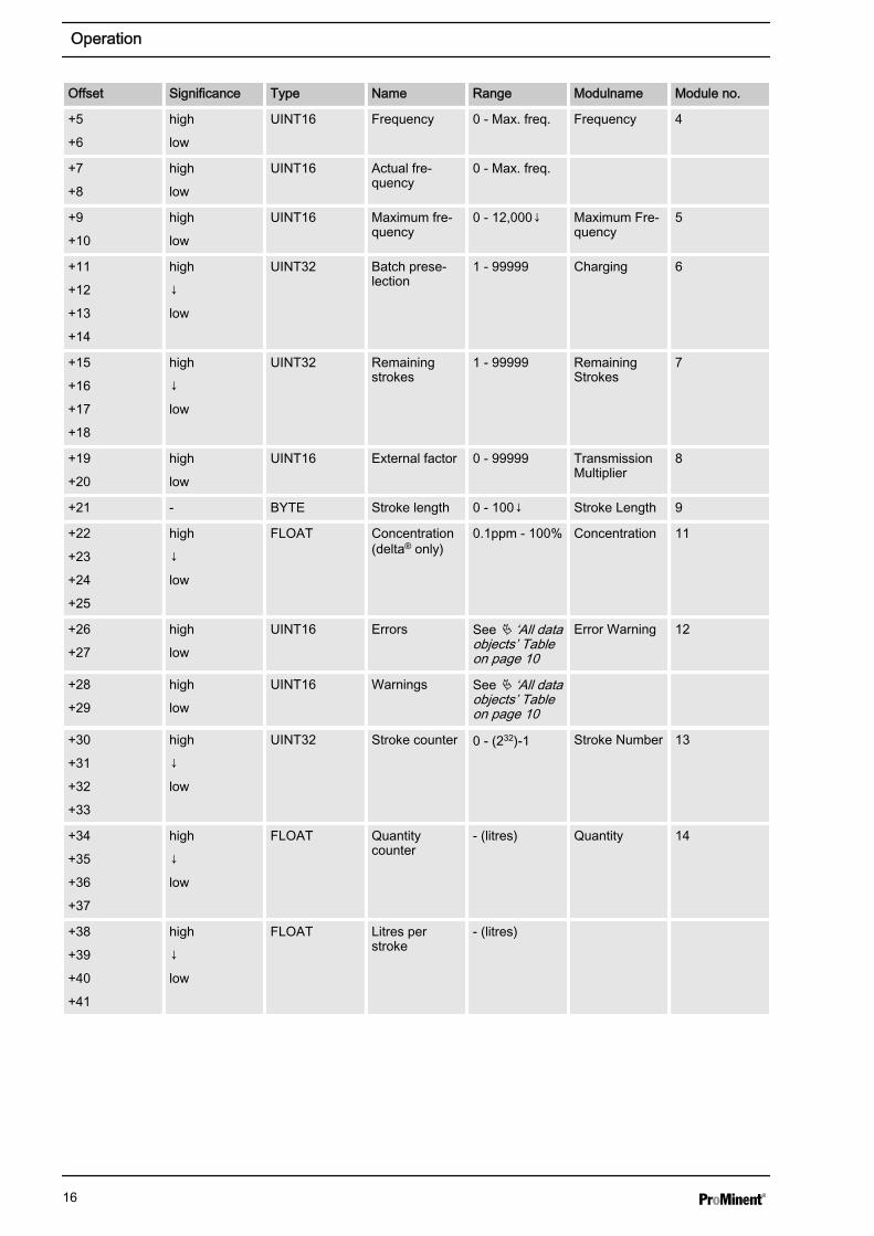
Offset Significance Type Name Range Modulname Module no.
+5
+6
high
low
UINT16 Frequency 0 - Max. freq. Frequency 4
+7
+8
high
low
UINT16 Actual fre‐quency
0 - Max. freq.
+9
+10
high
low
UINT16 Maximum fre‐quency
0 - 12,000↓ Maximum Fre‐quency
5
+11
+12
+13
+14
high
↓
low
UINT32 Batch prese‐lection
1 - 99999 Charging 6
+15
+16
+17
+18
high
↓
low
UINT32 Remainingstrokes
1 - 99999 RemainingStrokes
7
+19
+20
high
low
UINT16 External factor 0 - 99999 TransmissionMultiplier
8
+21 - BYTE Stroke length 0 - 100↓ Stroke Length 9
+22
+23
+24
+25
high
↓
low
FLOAT Concentration(delta® only)
0.1ppm - 100% Concentration 11
+26
+27
high
low
UINT16 Errors See Ä ‘All dataobjects’ Tableon page 10
Error Warning 12
+28
+29
high
low
UINT16 Warnings See Ä ‘All dataobjects’ Tableon page 10
+30
+31
+32
+33
high
↓
low
UINT32 Stroke counter 0 - (232)-1 Stroke Number 13
+34
+35
+36
+37
high
↓
low
FLOAT Quantitycounter
- (litres) Quantity 14
+38
+39
+40
+41
high
↓
low
FLOAT Litres perstroke
- (litres)
Operation
16

5.4.2 Configuration
On the master, you can select which modules are to take part is thecyclical data transfer. Modules and slots correspond to one another.Therefore, spaces (empty modules) must be configured for modules whichare not to be included.
The target configuration is defined in the form of identifiers. Ä ‘Modularstructure’ Table on page 14 specifies the identifier for each definedmodule in the final column.
The module identifiers must be set in ascending order, one after another.If you do not want the data of a module to be involved in cyclical datatransfer, then an empty module must be configured in this position.
Operation
17
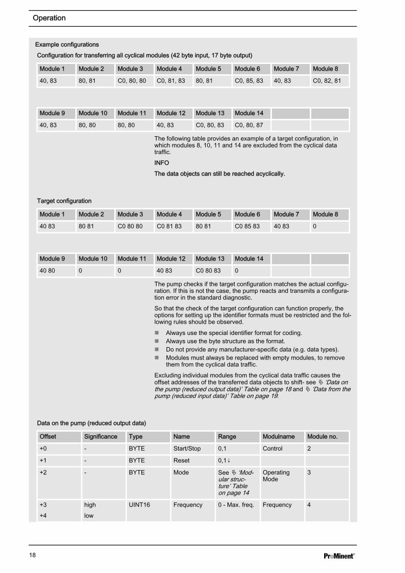
Configuration for transferring all cyclical modules (42 byte input, 17 byte output)
Module 1 Module 2 Module 3 Module 4 Module 5 Module 6 Module 7 Module 8
40, 83 80, 81 C0, 80, 80 C0, 81, 83 80, 81 C0, 85, 83 40, 83 C0, 82, 81
Module 9 Module 10 Module 11 Module 12 Module 13 Module 14
40, 83 80, 80 80, 80 40, 83 C0, 80, 83 C0, 80, 87
The following table provides an example of a target configuration, inwhich modules 8, 10, 11 and 14 are excluded from the cyclical datatraffic.
INFO
The data objects can still be reached acyclically.
Target configuration
Module 1 Module 2 Module 3 Module 4 Module 5 Module 6 Module 7 Module 8
40 83 80 81 C0 80 80 C0 81 83 80 81 C0 85 83 40 83 0
Module 9 Module 10 Module 11 Module 12 Module 13 Module 14
40 80 0 0 40 83 C0 80 83 0
The pump checks if the target configuration matches the actual configu‐ration. If this is not the case, the pump reacts and transmits a configura‐tion error in the standard diagnostic.
So that the check of the target configuration can function properly, theoptions for setting up the identifier formats must be restricted and the fol‐lowing rules should be observed.
n Always use the special identifier format for coding.n Always use the byte structure as the format.n Do not provide any manufacturer-specific data (e.g. data types).n Modules must always be replaced with empty modules, to remove
them from the cyclical data traffic.
Excluding individual modules from the cyclical data traffic causes theoffset addresses of the transferred data objects to shift- see Ä ‘Data onthe pump (reduced output data)’ Table on page 18 and Ä ‘Data from thepump (reduced input data)’ Table on page 19:
Data on the pump (reduced output data)
Offset Significance Type Name Range Modulname Module no.
+0 - BYTE Start/Stop 0,1 Control 2
+1 - BYTE Reset 0,1↓
+2 - BYTE Mode See Ä ‘Mod‐ular struc‐ture’ Tableon page 14
OperatingMode
3
+3
+4
high
low
UINT16 Frequency 0 - Max. freq. Frequency 4
Example configurations
Operation
18

Offset Significance Type Name Range Modulname Module no.
+5
+6
+7
+8
high
↓
low
UINT32 Batch prese‐lection
1 - 99999 Charging 6
+9 - BYTE Batch start 0,1↓
+10 - BYTE Batchmemory
0,1
+11 - BYTE Reset strokecounter
0,1↓ StrokeNumber
13
Data from the pump (reduced input data)
Offset Significance Type Name Range Modulname Module no.
+0
+1
+2
+3
high
↓
low
UINT32 Status See Ä ‘Dataon thepump’ Tableon page 15
Status 1
+4 - BYTE Mode See Ä ‘Mod‐ular struc‐ture’ Tableon page 14
OperatingMode
3
+5
+6
high
low
UINT16 Frequency 0 - Max. freq. Frequency 4
+7
+8
high
low
UINT16 Actual fre‐quency
0 - Max. freq.
+9
+10
high
low
UINT16 Maximum fre‐quency
0 - 12,000↓ MaximumFrequency
5
+11
+12
+13
+14
high
↓
low
UINT32 Batch prese‐lection
1 - 99999 Charging 6
+15
+16
+17
+18
high
↓
low
UINT32 Remainingstrokes
1 - 99999 RemainingStrokes
7
+19 - BYTE Stroke length 0 - 100↓ Stroke Length 9
+20
+21
high
low
UINT16 Errors See Ä ‘Alldataobjects’ Tableon page 10
Error Warning 12
Operation
19

Offset Significance Type Name Range Modulname Module no.
+22
+23
high
low
UINT16 Warnings See Ä ‘Alldataobjects’ Tableon page 10
+24
+25
+26
+27
high
↓
low
UINT32 Strokecounter
0 - (232)-1 StrokeNumber
13
5.5 Acyclical data traffic
(from DP-V1)
The acyclically transferred data is addressed via slot and index. All datasummarised under one slot can then be addressed individually using theindex, and acyclically transferred.
Slots are identical to the modules for cyclical transfer.
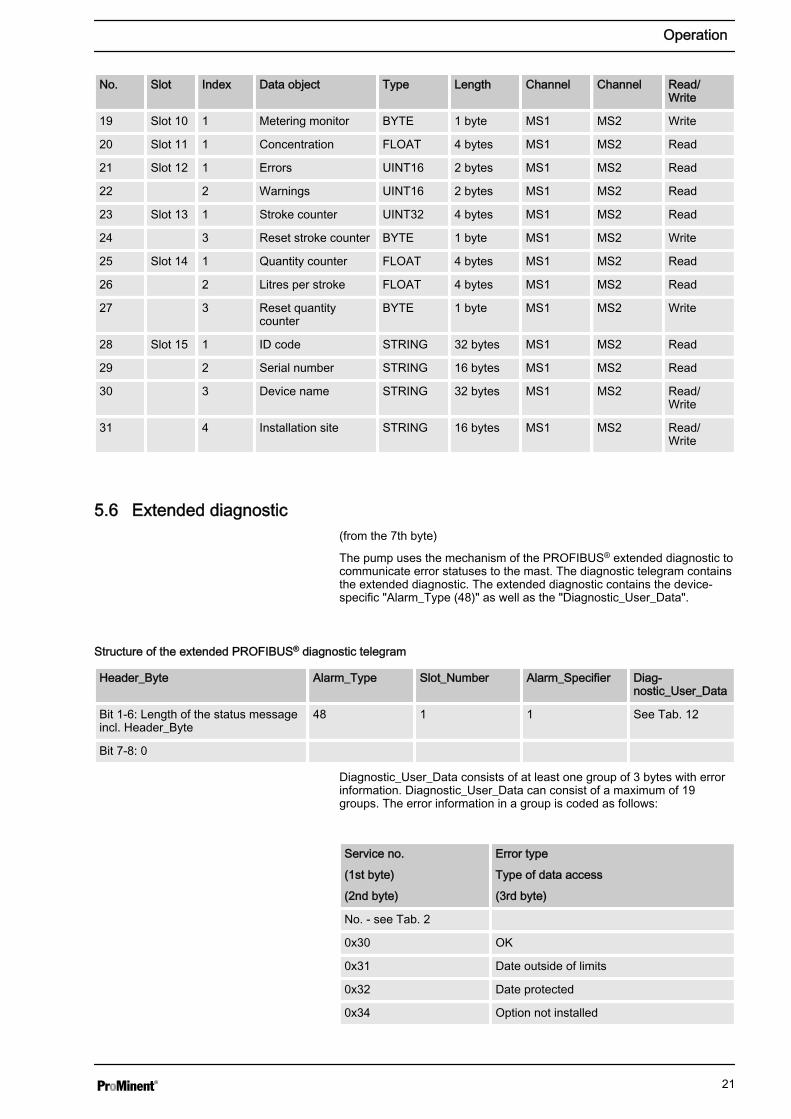
Slots of the acyclical data objects
No. Slot Index Data object Type Length Channel Channel Read/Write
0 Slot 0 1 Device identification UINT32 4 bytes MS1 MS2 Read
1 Slot 1 1 Status UINT32 4 bytes MS1 MS2 Read
2 Slot 2 1 Start/Stop BYTE 1 byte MS1 MS2 Write
3 2 Reset BYTE 1 byte MS1 MS2 Write
4 Slot 3 1 Mode BYTE 1 byte MS1 MS2 Write
5 2 Mode BYTE 1 byte MS1 MS2 Read
6 Slot 4 1 Frequency UINT16 2 bytes MS1 MS2 Write
7 2 Frequency UINT16 2 bytes MS1 MS2 Read
8 3 Actual frequency UINT16 2 bytes MS1 MS2 Read
9 Slot 5 1 Maximum frequency WORD 2 bytes MS1 MS2 Read
10 Slot 6 1 Batch preselection UINT32 4 bytes MS1 MS2 Write
11 2 Batch preselection UINT32 4 bytes MS1 MS2 Read
12 3 Batch start BYTE 1 byte MS1 MS2 Write
13 4 Batch memory BYTE 1 byte MS1 MS2 Write
14 Slot 7 1 Remaining strokes UINT32 4 bytes MS1 MS2 Read
15 Slot 8 1 External factor UINT16 2 bytes MS1 MS2 Write
16 2 External factor UINT16 2 bytes MS1 MS2 Read
17 4 External factor BYTE 1 byte MS1 MS2 Write
18 Slot 9 1 Stroke length BYTE 1 byte MS1 MS2 Read
Operation
20
No. Slot Index Data object Type Length Channel Channel Read/Write
19 Slot 10 1 Metering monitor BYTE 1 byte MS1 MS2 Write
20 Slot 11 1 Concentration FLOAT 4 bytes MS1 MS2 Read
21 Slot 12 1 Errors UINT16 2 bytes MS1 MS2 Read
22 2 Warnings UINT16 2 bytes MS1 MS2 Read
23 Slot 13 1 Stroke counter UINT32 4 bytes MS1 MS2 Read
24 3 Reset stroke counter BYTE 1 byte MS1 MS2 Write
25 Slot 14 1 Quantity counter FLOAT 4 bytes MS1 MS2 Read
26 2 Litres per stroke FLOAT 4 bytes MS1 MS2 Read
27 3 Reset quantitycounter
BYTE 1 byte MS1 MS2 Write
28 Slot 15 1 ID code STRING 32 bytes MS1 MS2 Read
29 2 Serial number STRING 16 bytes MS1 MS2 Read
30 3 Device name STRING 32 bytes MS1 MS2 Read/Write
31 4 Installation site STRING 16 bytes MS1 MS2 Read/Write
5.6 Extended diagnostic
(from the 7th byte)
The pump uses the mechanism of the PROFIBUS® extended diagnostic tocommunicate error statuses to the mast. The diagnostic telegram containsthe extended diagnostic. The extended diagnostic contains the device-specific "Alarm_Type (48)" as well as the "Diagnostic_User_Data".
Structure of the extended PROFIBUS® diagnostic telegram
Header_Byte Alarm_Type Slot_Number Alarm_Specifier Diag‐nostic_User_Data
Bit 1-6: Length of the status messageincl. Header_Byte
48 1 1 See Tab. 12
Bit 7-8: 0
Diagnostic_User_Data consists of at least one group of 3 bytes with errorinformation. Diagnostic_User_Data can consist of a maximum of 19groups. The error information in a group is coded as follows:
Service no.
(1st byte)
(2nd byte)
Error type
Type of data access
(3rd byte)
No. - see Tab. 2
0x30 OK
0x31 Date outside of limits
0x32 Date protected
0x34 Option not installed
Operation
21

Service no.
(1st byte)
(2nd byte)
Error type
Type of data access
(3rd byte)
0x35 Service not defined
0x36 Value cannot be changed
0x37 Update complete
0x55 Communications error
0xD3 Write access
0xE5 Read access
Operation
22