The Camden journal (Camden, S.C.).(Camden, S.C.) 1836-04 ...

RC C&W Page 1
Supervisors Training Centre, S.C.Rly
Refresher Course (C&W) Study Material
October 2018

RC C&W Page 2

RC C&W Page 3
1. Pattern of Freight Train Examination as per latest JPO No. 7/2014
As per JPO No. 7/2014, there shall be only three types of examinations for freight stock. i. Closed Circuit Rake Examination (CC rake)
ii. Premium Rake examination. iii. End to End examination
i. CC rake Examination (Periodical Monitoring Examination (PME) a. Only Off POH/ Off ROH wagons fitted with air brake system should be inducted as new
CC rakes under normal circumstances. For formation of CC rakes other than this, CRSE’s approval is required, which should be recorded in writing.
b. CC rake shall be given 100% brake power during PME at original base depot. c. CC rake examination is to be conducted only at nominated base depot. Code of base
depot is to be stenciled on all the wagons. d. The BPC of the rake shall be valid for 7500 kms or 35 days whichever is earlier.
However, for BLC rakes BPC shall be valid for 6000 kms or 30 days whichever is earlier. Within this validity rake can subjected to any no. of loading/unloading.
e. After loading, at every loading point the CC rake BPC shall be revalidated in the form of GDR check as stipulated in Para 12.0 of the JPO.
f. CC rakes are allowed to run only in the circuit of the nominated zones. g. Colour of BPC shall be yellow. h. The CC rake BPC becomes invalid under the following conditions. These rakes have to
be cleared up to next examination point in the direction of movement for examination and issuance of a fresh BPC upto PME depot. HQs Operating and C&W Control should be appraised of all such cases so that the rakes can be brought to the PME depot within 40days from the day of issue of BPC. If rake integrity disturbed by more than 4 wagons within the validity of the BPC.
Only up to 4 wagons attachment/detachment is permitted en route during the validity of the BPC.
If the rake stabled for more than 24 hours at nominated TXR examination yard / any other station, except the loading/unloading point.
If CC rakes moved to any other zone not mentioned in the circuit. If overdue CC rake is not moved in the direction of PME depot. If the driver fails to log the kilometers on the BPC correctly. (BPC of such CC rakes
will deem to be valid only for 20 days. ii) Premium End to End Rake examination:
a. Premium End – to End rakes will be formed out of Air Brake open stock (BOXN, BOXNHA, BOXNHS), covered stock (BCN, BCNA, BCNA HS), BOBR and BOBRN. On S. C. Railway, Premium End-to-End rakes will be intensively examined in empty condition and certified by examination points at BPA, RDM, GY, BZA, COA, SNF and PAU on the nominated lines, (’A’ category depots or depots should be upgraded to “A” category depots).
b. Brake power certificate issued for such premium end-to-end rakes will be valid for 12 days from the date of issue. During this 12 day period, the rakes will be allowed multiple loading/unloading. Loading after 12th day should be prohibited so that the rake is not overdue.
c. After the lapse of 12 days, the rake should be offered for next intensive examination at the first examination point in the direction of movement. To avoid examination in loaded condition, a grace period of 3 days be permitted, if the rake is in loaded condition on 12th day.

RC C&W Page 4
d. However, after expiry of the grace period, i.e., after a lapse of 15 days from the day of issue of BPC, even a loaded premium rake shall be offered for examination at the first train examination point in the direction of movement and BPC is issued in End to End format up to the unloading point only.
e. Brake power certificate for premium end-to-end rakes to be issued with proper format in green colour paper.
f. Minimum brake power should be 95% at originating station. g. The movement of Premium end to end rakes will be monitored through FOIS by traffic.
iii) End to End examination: All trains which are not checked in the CC or Premium rake examination will come under this category. This is for all stocks including mixed stock where freight wagons are available.
a. Empty rakes shall be offered in full formation for examination and issue of BPCs. Thereafter C&W staff will carry out no further examinationafter loading. After such examination, the empty rake should be moved to the loading station as per the requirement of traffic.
b. The validity of BPC for an empty rake will be given at the train examining point as “Up to loading point & further up to unloading point”. But after loading the rake, the operating staff (commercial staff if no operating staff is posted at that station) shall ensure that the destination of the loaded train is clearly mentioned on the BPC and the same BPC valid up to destination.
c. The empty rake must reach the loading point within 4 days of the issue of BPC including the day of issue, for the loaded rake to move on the same BPC.
d. No driver shall move the loaded train from the loading point unless the destination is clearly mentioned on the BPC. BPC of the loaded train without destination shall be treated as invalid.
e. Green color BPC for Air brake stock and Pink color BPC for Vacuum Brake stock shall be used for such rakes.
f. Minimum brake power should be 90% for Air Brake stock and 85% for Vacuum Brake stock to be maintained at originating station after Intensive Examination.
2. Procedure of intensive examination for Freight Stock The following procedure is to be followed for conducting intensive examination of freight
trains a) Rolling-in examination including axle box feeling for detection of any defects like flat
tyre, loose parts, hanging parts and worm box. b) Incoming BPC to be collected. c) Inspection and repair of running gear fittings. d) Inspection and repair of brake gear and spring gear. e) Inspection and repair of draw and buffing gear. f) Checking and making good the deficiency of safety fittings, safety brackets, safety loops
etc. g) Replacement of brake blocks, correct maintenance of SAB “A” dimension and piston
stroke. Minimum yard leaving Brake Block thickness – 20mm
SAB “A” dimension – CASNUB bogie 70 +2/-0mm
BOBRN, BLC 27+2/-0mm

RC C&W Page 5
Piston stroke –
STOCK Empty Load
BOXN, BCN, BCNA, BRN, BTGLN 85±10MM 130±1010MM
BTPN 87±10MM 117±10MM
BVZC 70±10MM
BOBRN/BOBYN 100±10MM 110±10MM
h) Correct fitment of washers, bulb cotters and all brake gear pins to be ensured. i) Correct functioning of empty/load device. j) Checking and securing of air brake components for their proper functioning and
fitment. k) Wheel profile to be checked for rejectable defects. l) Visual examination of Bogie frame and spring for cracks/breakage. m) Ensure correct requirement of brake power as per JPO No. 7/2014
1. CC rakes – 100% 2. Premium rakes – 95% 3. End to End rakes – 90%
n) Issue BPC in proper format as per JPO No. 7/2014. 3. Classification of goods stock
Goods stock is mainly classified according to their shape of the body 1. Open wagons: These are used for transportation of Ores, Granite stones and some Steel products etc. which are not affected with changes in atmosphere. Example-BOXN, BOXNR, BOXNHL etc. 2. Covered Wagons: These are used for transportation of food grains, sugar, cement etc. which would spoil due to changes in atmosphere like rains etc. Example- BCN,BCNA,BCNHL etc. 3. Flat Wagons: These are used for transportation of steel consignments Example: BRN, BRNA etc 4. Hopper Wagons: These are used for quick and mass transportation of food grains, coal etc. and transportation and lying of ballast for departmental use. Example: BOBRN & BOBYN 5. Container Wagons: These are used for transportation of containers Example: BFKN, BLC 6. Tank Wagons: These are used for transportation of liquids and gases like petrol, k.oil, LPG etc. Example: BTPN,BTPGLN etc. 7. Well Wagons: These wagons are specially designed for carrying specific items like boilers, parts of turbines etc. Example: BWL 8. Brake Van: These are utilized by the guard of the train Example: BVZC, BVZI, BVCM

RC C&W Page 6
4. POH & ROH periodicity of various goods stock
SN WAGON CODE POH ROH
1st Subs 1st Subs
1 BOXN,BRN 6y 4 ½ y 1 ½ y 1 ½ y
2 BCN, BCNA,BOBRN 6y 6y 2y 2y
3 BTPN 6y 6y 1 ½ y 1 ½ y
4 BTPGLN 4y 4y 2y 2y
5 BOY 3y 3y 1 ½ y 1 ½ y
6 BTALN 4 ½ y 4 ½ y 1 ½ y 1 ½ y
7 BOI, BOM, BTAL 4 ½ y 4 ½ y 1 ½ y 1 ½ y
8 Brake Vans 2 y 2y - -
9 Departmental stock 4 y 4 y - -
10 Domestic containers 1 ½ y 1 ½ y - -
5. Different types of CASNUB bogies with salient features
The different types of CASNUB Bogies are: - CASNUB 22W W – Wide jaw CASNUB 22W (Retro) R–Retrofitted CASNUB 22W (M) M – Modified CASNUB 22NL N – Narrow jaw,L – Light weight CASNUB 22NLB B – Bharat & co CASNUB 22NLM M –Mukund& co CASNUB 22HS HS –High Speed. These bogies are used in – BOXN, BCN, BCNA, BRN, BTPN, BOBRN, BOBY, BOBYN, BLC. Bogie construction: - The bogie comprise of two cast steel side frames and a floating Bolster.
The bolster is supported on the side frames through two nests of springs. This also provides a friction damping proportional to load. Fabricated mild steel spring plank connects the side frame to maintain the bogie square. This bogie is fitted with tapered cartridge roller bearing axles.
Salient features: - Axle load : 20.3 t, however all bogies except CASNUB 22HS now upgraded to 22.9t Wheel base : 2000±5 mm Wheel diameter : New - 1000 mm & 956 mm only for CASNUB 22WR Condemning – 906mm for all types Type of axle bearing : Standard AAR Tapered Cartridge roller Bearing (CTRB) Distance between journal centers – 2260 mm Distance between side bearers – 1474 mm Type of side bearer -- Roller type (clearance type) – Fitted on CASNUB 22W
--CCMBR Pads–Fitted on CASNUB 22WR, CASNUB 22W (M), 22NL, 22NLB, 22NLM Trolleys.
--Spring loaded – Fitted on CASNUB22HS&LCCF20C(BLC) -- All the above side bearers are removed and PU (Poly Urethane) pads
are to be fitted during POH / ROH Type of centre pivot – IRS Type – Fitted on CASNUB 22W Trolleys.
- Spherical type – Fitted on CASNUB 22W(M), 22NL, 22NLB, NLM& 22 HS Bogies. - Flat pivot provided on CASNUB 22HS fitted to BCNHL, BOXNHL& BLC

RC C&W Page 7
Type of brake beam – Unit type fabricated brake beam Fitted on CASNUB22W supported and guided in the brake 22NL, 22NLB,22NLM &
beam pocket 22HS Bogies. -Unit type cast steel brake beam suspended Fitted on
by hangers from side frame brackets. 22W(M) Suspension – Long travel helical springs comprising Inner, Outer and snubber springs. 6. ROH procedure of BOXN wagons:
ROH PERIODICITY: - 18 monthsforBOXN wagons
24 monthsforBCN wagons
ROH PROCEDURE: - DISMANTLING:- Collect and note down PRO particulars of BOX N/BCN wagon to be attended for ROH
Take initial readings such as Coupler height from Rail level and note down other defects.
Disconnect bogie brake rigging to under frame and under frame brake gears. Lift the body, run out the bogies and keep the body on trestles. Strip the bogie components and insert assembly pins (12mm and 250 mm long) to
retain friction shoes (Snubber wedges) Raise the bolster to connect top members of side frame and remove all the outer, inner
and snubber springs. Remove the assembly pins and lower wedge blocks to take them out. Lower the bolster to rest on the spring flank. Examine bogie spring plank for cracks and check side frame alignment by trammeling
Gauge as follows: - o Wheel base – 2000 + 5 mm o Journal centre – 2260 + 5 mm o Diagonal distance of Trolley frame – 3018 + 5 mm.
Take out side frame keys and adopter retaining bolts. Lift side frame and spring plank assembly and release the adopters and wheel sets. Slide Bolster to one side to check up the column liner plates, slope liner, Land surface,
Anti rotating lugs and Bolster column with prescribed gauges and use suitable thickness Sims.
Check up for wear on pedestal jaw and Adopters. Check up wear on Wedge. Check centre pivot for cracks and wear.
ASSEMBLING OF BOGIE COMPONENTS:-
Replace all worn out pins and bushes. Replace new brake blocks. Reassemble the coil springs in nest after pairing, that is in one nest the variation
of free height of the springs not more than 3 mm. Mixing up of new and old springs should be avoided.
Check the wheel profile. If required replace the wheels with ultrasonically tested wheels.
Check up the side bearer rubber pads and Elastomeric rubber pads for cracks and free height, if necessary replace with new one.

RC C&W Page 8
Lower the body on the bogie after sprinkling Graphite powder in the centre pivot.
Check the CBC heights if necessary keep the (CBC) Buffer height pickings in between Adopter and Elastomeric pads.
Lubricate all the pins. Replace all the worn out brake gear pins and use over hauled SAB and adjust A
and E dimensions and tack weld the anchor pin. ‘A ' dimension must be 70 + 2 /-0 mm. 'E ' dimension must be 555 mm to 575 mm. Check the CBC operating handle for any defect and free of operation. Check the Draft gear, Yoke, CBC shank, Knuckles for wear and cracks if necessary
replace by new ones. Check hand brakes and doors for easy movement. Check up Empty/Load gear arrangement and paint Yellow and Black respectively
for easy identification and set the empty tie rod check nuts correctly, if required. Provide side frame keys. Clean the Dirt collectors and Brake cylinder strainers. Change the defective Air hose assembly. Examine and lubricate Cut off angle cocks and change if required. Examine and attend leakages of all pipes and joints. Carry out the Single wagon test for proper functioning of Air brake system. Carry out the medications recommended by RDSO and other authorities Touch up paint for sole bar and stencil station and date.
7. Modifications to be carried out on wagon stock during ROH:
The striker casting wearing plate is modified and secured by means of bolts and nuts with the striker casting to prevent working out of wearing plates on run.
A stopper is welded at an angle of 20º with the vertical on the air hose carrier suspension bracket, to prevent the excessive displacement of air hose carrier on run. This modification prevents damages to the air hoses.
Metallic bushes are used in the brake rigging instead of nylon bushes, to prevent frequent replacement of bushes.
Bulb cotters are used instead of split cotters. Worn wheel profile is adopted for the RB wheels. Truss beams are strengthened near brake heads by welding three numbers of MS
strips to the length of 215 mm to prevent the truss beams from getting crack near the brake heads.
Bogie push rods are provided with safety straps on either ends to prevent the dropping of truss beams on run, whenever the pins are working out. A bolt is fitted with the floating lever to keep the bogie push rod in position, in case the pin fails.
Load empty horizontal lever support bracket is strengthened at the joint with the body by welding gusset plates at the joint.
An anti rotation lug is welded between the sleeve nut and screw rod of empty tie rod to prevent the tampering of empty tie rod.
Control rod diameter of SAB is increased from 28 mm to 32 mm, to prevent the control rod from getting bent.
An additional support bracket is given for supporting the SAB pull rod to prevent malfunctioning of SAB enroute.
The centre pivots are secured by means of rivets, to prevent the trolleys from getting shifted.

RC C&W Page 9
Quick couplings are used in the brake vans, to facilitate easy fitment and removal of pressure gauges.
For Casnub 22 W retrofitted bogie, the centre pivot bottom is cut by 5 mm at the top of the projected portion, to prevent the jamming of pivots.
8mm strips are to be welded on either side hand brake wheel spindle 150mm away from sole bar to avoid accidental working out of hand brake wheel from its position when the sleeve and its riveting is defective.
8. Modifications to be carried out to convert CASNUB – 22W to CASNUB– 22WR:
The following modifications are to be carried out to convert a CASNUB 22W into a 22WR (retrofitted):
Introduce Elastomeric pad to the thickness of 45mm between side frame and adaptor. The maximum permissible wheel diameter is to be restricted to 956mm. Provide modified adaptor with reduced height of 129.5mm instead of 152.5mm.
Side frame key is to be reversed and should be fitted from bottom of jaw. Provide constant contact rubber bonded side bearer instead of Roller type side bearer. Cut the centre pivot bottom by 5mm at the top of the projected portion to prevent the
jamming of pivots.
Retainer bolt hole should be shifted by 25 mm below, from the position of existing hole.

RC C&W Page 10
9.Maintenance of departmental wagons in open line: Maintenance of departmental wagons falls under the category of End to End intensive
examination. Types of departmental wagons:
i.Sleeper carriers ii.Rail carriers
iii.Ballast wagons iv.10RP/20RP carriers (rails of 130m/260m lengths).
BCXSC, BOXSC etc. are the wagons used as sleeper carriers as well as rail carriers. These
wagons are made out of over aged BCX, BOX wagons by removing the end walls and side walls to enable mechanized loading and unloading at PQRS (Plaser Quick Relaying System).
BOBYN wagons which are specially designed for carrying and lying of ballast are categorized as ballast carriers.
Modified BRN/BRNA wagons are categorized as 10RP/20RP (Rail Panels) carriers which are used to carry the rails from manufacturing unit to site.
All the departmental wagons are to be based at nominated depot and code of the base depot should be clearly stenciled on these wagons.
Normally all the departmental wagons are to be examined intensively in empty condition.
In case of Sleeper carriers, Rail carriers and Ballast carriers fresh BPC will be issued after intensive examination.
The originating Brake Power of these trains would be 90%.
The validity of BPC for wagons having CANUB bogies with Air Braked stock will be for 30 days without weekly revalidation.
The validity of BPC for wagons having UIC bogies with Air Braked stock will be for 30 days with fortnightly revalidation.
After loading / unloading GDR check should be conducted in view of safety of the train. 10. Rolling in and Rolling out examination and advantages: 10.1. Rolling in Examination All terminating and pass through trains are given rolling in examination, while entering a
station with C&W depot. JE/SSE(C&W) and his staff should take up position on both sides of the line short of the normal halting place on which the train is to be received and the following inspection should be carried out. Look out for any loose or dangling components. Observe whether there are any flat places on the tyre (skidded wheel). Observe and listen for any worm axle box (damages in roller bearing). Defective / broken springs. Defective / drooping buffers. Abnormal behaviour of any of the vehicles, or any other observations which may
lead to unsafe working condition. Rolling out Examination
Similarly, while the train is leaving from the plat form/yard, rolling out examination is also to be conducted to avoid the above mentioned defects and the last minute detentions.
Advantages of conducting Rolling in/out examination:
It will reveal the defects of rolling stock which can’t be identified/checked when it is stabled.
This simple examination will save lot of time and avoid major disasters.

RC C&W Page 11
11. Various wheel defects and their effects with limits of rejections:
Wheel defects Standard Condemning Limit
Sharp Flange 14.5mm 5 mm or Less
Thin Flange 28.5mm /
29.4mm
16mm or Less for trains upto 110 kmph 22mm or less for 110 kmph& above
Coaches
Less radius at root of flange
16mm-IRS 14mm-WWP
13 or Less
Hollow Tyre ----- 5 mm or above
Deep Flange 28.5mm 35mm or more
Thin Tyre ----- 25 mm or Less
Flat Tyre ----- 50 mm or more – for Coaching 60 mm or more – for Goods
Effects of Wheel defects: a. Sharp flange: when allowed in to service it leads the vehicle to two roads while
negotiating defective points/crossings. b. Thin flange: when allowed into service worn-out flange will break due to
longitudinal reaction by track and vehicle derails. c. Less radius root: It will lead to excessive angle of attack and lead to climbing of
flange on to rail table and leads to derailment. d. Hollowtyre and Deep flange: Often these two will appear on wheel tread
together. When allowed into service results in rough riding with noise and damages fish plates and fish bolts of the track disconnects the rail joints. This will cause the following train to derail.
e. Thin tyre: When solid wheels have reached to its lowest allowed wheel diameter, the load bearing capacity of the wheel reduce drastically and will get sheared under the heavy rolling loads causing major disaster.
f. Flat tyre: This will cause hammer blow effect on the rails and rail fittings while in run.
RC C&W Page 12
12. Worn wheel profile:
Worn wheel profile is a special profile on wheel tyre derived out of standard wheel profile suitable to worn shape of rail head of which are of 80% track in IR. This is to minimise the Condemnation period to avoid frequent wheel changing, reprofiling and enhance the life of the wheel. This profile is totally replacing the IRS standard wheel profile as standard wheel profile found not economical and not surviving for more number of kms due to the fact that it has to run on worn rail heads which is mismatch to standard wheel profile. 13. Wheel defects to be observed as per CMI K-003:
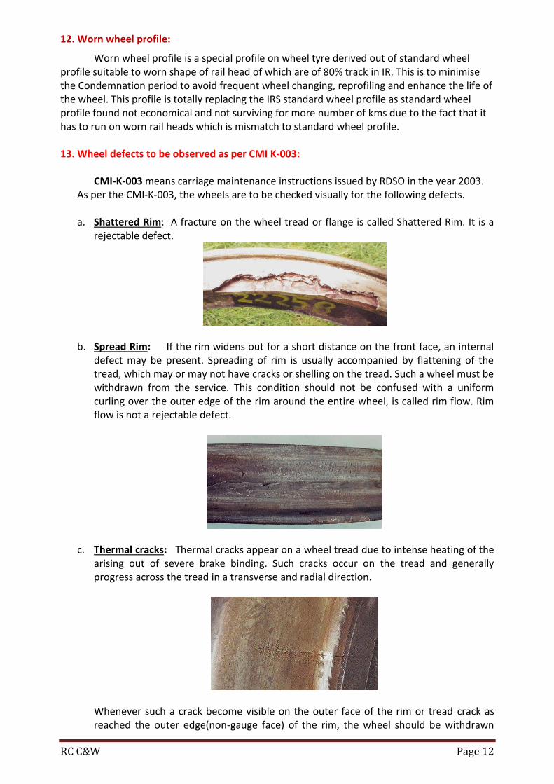
CMI-K-003 means carriage maintenance instructions issued by RDSO in the year 2003. As per the CMI-K-003, the wheels are to be checked visually for the following defects. a. Shattered Rim: A fracture on the wheel tread or flange is called Shattered Rim. It is a
rejectable defect.
b. Spread Rim: If the rim widens out for a short distance on the front face, an internal defect may be present. Spreading of rim is usually accompanied by flattening of the tread, which may or may not have cracks or shelling on the tread. Such a wheel must be withdrawn from the service. This condition should not be confused with a uniform curling over the outer edge of the rim around the entire wheel, is called rim flow. Rim flow is not a rejectable defect.
c. Thermal cracks: Thermal cracks appear on a wheel tread due to intense heating of the
arising out of severe brake binding. Such cracks occur on the tread and generally progress across the tread in a transverse and radial direction.
Whenever such a crack become visible on the outer face of the rim or tread crack as reached the outer edge(non-gauge face) of the rim, the wheel should be withdrawn

RC C&W Page 13
from the service. If a crack becomes visible on the outer flange face, the wheel withdrawn from service. Such wheels should be sent to workshops for examinations and subsequent rejections. Wheels involved in service brake binding should be examined carefully during the maintenance to rule out the possibility reject able thermal cracks. Such wheels maybeidentifiedbythepresenceofflats(may be within acceptable limits) and severe discoloration or blue black heating marks on the tread.
d. Heat checks: Thermal cracks are deeper and need to be distinguished from fine
superficial cracks visible on the tread on or adjacent to the breaking surface. These are called heat checks, which are usually denser than thermal cracks. Heat checks are caused on the tread due to heating and cooling cycles undergone by the wheel during normal breaking. Such wheels do not need to be withdrawn but should be carefully distinguished from the reject able thermal cracks.
e. Shelled Tread: Shelling can be identified by pieces of metal breaking out of the tread
surface in several places more or less continuously around the rim. Shelling takes place when small pieces of metal breakout between the fine thermal cracks. These are generally associated with small skid marks or “chain sliding”. Such wheels should be withdrawn from service and sent to workshops for reprofiling.
f. Disc crack: A crack on the disc due to material failure is called disc crack. Disc crack of
any length on disc plate is a rejectable defect. 14. New Wagon numbering system from 2003: New wagon numbering system introduced on Indian Railways from the year 2003. According to this system wagon number contains “11” digits.
First 2 digits indicates type of wagon (1st& 2nd ) Next 2 digits indicate owning railway (3rd&4th ) Next 2 digits indicates year of manufacture (5th& 6th ) Next 4 digits indicates individual wagon number (7th ,8th ,9th&10th ) Last digit is a check digit (11th )
RC C&W Page 14
C1 C2 C3 C4 C5 C6 C7 C8 C9 C10 C11
Type of wagon
Owning Railway Year of
manufacture Individual wagon number Check digit
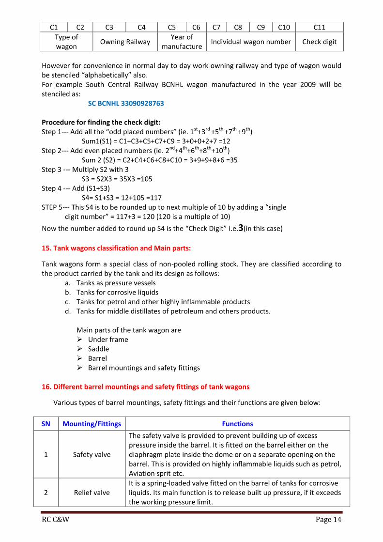
However for convenience in normal day to day work owning railway and type of wagon would be stenciled “alphabetically” also. For example South Central Railway BCNHL wagon manufactured in the year 2009 will be stenciled as: SC BCNHL 33090928763 Procedure for finding the check digit: Step 1--- Add all the “odd placed numbers” (ie. 1st+3rd +5th +7th +9th) Sum1(S1) = C1+C3+C5+C7+C9 = 3+0+0+2+7 =12 Step 2--- Add even placed numbers (ie. 2nd+4th+6th+8th+10th) Sum 2 (S2) = C2+C4+C6+C8+C10 = 3+9+9+8+6 =35 Step 3 --- Multiply S2 with 3 S3 = S2X3 = 35X3 =105 Step 4 --- Add (S1+S3) S4= S1+S3 = 12+105 =117 STEP 5--- This S4 is to be rounded up to next multiple of 10 by adding a “single digit number” = 117+3 = 120 (120 is a multiple of 10)
Now the number added to round up S4 is the “Check Digit” i.e.3(in this case)
15. Tank wagons classification and Main parts:
Tank wagons form a special class of non-pooled rolling stock. They are classified according to the product carried by the tank and its design as follows:
a. Tanks as pressure vessels b. Tanks for corrosive liquids c. Tanks for petrol and other highly inflammable products d. Tanks for middle distillates of petroleum and others products.
Main parts of the tank wagon are
Under frame Saddle Barrel Barrel mountings and safety fittings
16. Different barrel mountings and safety fittings of tank wagons
Various types of barrel mountings, safety fittings and their functions are given below:
SN Mounting/Fittings Functions
1 Safety valve
The safety valve is provided to prevent building up of excess pressure inside the barrel. It is fitted on the barrel either on the diaphragm plate inside the dome or on a separate opening on the barrel. This is provided on highly inflammable liquids such as petrol, Aviation sprit etc.
2 Relief valve It is a spring-loaded valve fitted on the barrel of tanks for corrosive liquids. Its main function is to release built up pressure, if it exceeds the working pressure limit.

RC C&W Page 15
3 Safety vent
This consists of frangible disc (lead or any approved material not affected by lading), which ruptures at specified pressure. It is an additional safety fitting to safeguard against the failure of the relief valve. When the built up pressure exceeds the working pressure of the relief valve and the latter fails to function for any reason the frangible disc of this safety vent ruptures to release the pressure.
4 Compressed air valve It is provided on tank from which the contents are unloaded by compressed air. Its main function is to control the rate of discharge by controlling the rate of air admission.
5 Vapour extractor cock Its function is to extract vapour from the tank while f i ll in g
6 Master valve It is a gravity discharge valve fitted with a hand wheel in the dome for manual operation.
7 Bottom discharge valve
BG 4-Wheeler Bottom discharge valve are provided with single bottom discharge valve situated underneath the master valve while on BG/MG eight wheeler stock two bottom discharge valves are fitted, one on either side and connected with the master valve through a “T” pipe. The main function of the valve is to control the flow of the contents and also to serve as an additional safety stop in case the master valve fails or breaks. The bottom discharge valve openings are also provided with blank flanges to be used with 2mm compressed asbestos fibre jointing material to serve as further check on accidental leakage of contents.
17. Steam cleaning of Tank Wagons:
The tanks requiring steam cleaning should be placed as near the steam supply line as possible and protected against any movement. The berthing siding should be completely isolated from all other traffic. Tanks as pressure vessels, tanks for petroleum, other highly inflammable products, vegetable oils, bitumen, coal tar and molasses are cleaned by steam. In case of pressure vessels, it should be ensured that all the gas has been discharged to the atmosphere. After ensuring that the tank barrel is no longer under pressure, the following sequence should be followed:
i) Remove the manhole cover together with manhole housing, valves etc. and leave the tank exposed to atmosphere for 24 hours.
ii) Entry of staff in the tank barrel should be strictly prohibited and signs with suitable legends displayed at a reasonable distances away from the tanks to be steam cleaned.
iii) Insert pipe through manhole and steam the interior of barrel for 12 hours. In order that the tank barrel is thoroughly steamed from inside, the steam pipe should be provided with a “T” connection at its lower end and so directed as to blow steam towards both ends.
iv) Remove condensed steam collected in the tank barrel and keep the barrel exposed to atmosphere for another 24 hours.

RC C&W Page 16
18. Different Tests for Tank Wagons:
The following are the tests that should be conducted to ensure the tanks are free from contamination gases of the contents. a) AMMONIA TANK BARREL
a. Fill the tank barrel with water.
b. Collect a specimen of the water in a clean glass bottle.
c. Test the specimen of the water with red litmus paper. If the colour of the litmus paper turns into blue, it indicates that the barrel is still having the gases of ammonia and requires steam cleaning.
NESSLER’S TEST Test the specimen of the water with a mixture of potassium mercuric iodide and
potassium hydroxide. If the colour of the mixture turns into brown, it indicates that the barrel is still having the gases of ammonia and requires steam cleaning b) CHLORINE TANK WAGONS
a. Fill the tank barrel with water. b. Collect a specimen of the water in a clean glass bottle. c. Test the specimen of the water with red litmus paper. If there is any bleaching effect on
the litmus paper, it indicates that the barrel is still having the gases of chlorine and requires steam cleaning.
c) LPG TANK WAGONS
a. Fill the fresh water in a clean bottle. A string is to be attached to the bottom of the bottle.
b. Lower the bottle through the manhole up to the bottom of the tank and tilt the bottle. Allow the water to flow out and let the gas get into the bottle.
c. Wait for 5 minutes and lift the bottle and withdrawn away from the tank. d. Bring a lighted matchstick near the mouth of the bottle. If there is no flame it is free
from injurious gas. But in case it gives out a flame, the tank should again be steam cleaned.
19. Checks to be carried out by C&W supervisor before certifying the tank wagon for loading and precautions to be followed when there is leakage from loaded tank:
Master Valve: Leakage of master valve should be checked while keeping the bottom discharged valve in open.
Bottom discharge Valve: Proper functioning and fluid tightness of the bottom discharge Valve should be ensured.
Blank flange: The blank flange of the correct thickness made out of steel plate and with a gasket of proper material between the blank flange and bottom discharge valve flange should be tightened by six bolts and nuts.
Tank barrel: Tanks with cracks on barrels should be marked sick. Leaky Tank barrels: The leakage of tank barrels may be caused due to the following reasons.
i. Mechanical injury to the valve face and /or valve seat as a result of foreign material, particularly nuts and bolts finding their way inside the tank wagon.
ii. Valves seat not properly secured to the stool by proper interference fits. iii. Mal functioning of master valve.

RC C&W Page 17
When leakage is found from the Chlorine and Ammonia tanks; Chlorine and ammonia gases are poisonous and have a characteristic pungent odour,
which gives warning of their presence in the atmosphere before dangerous concentrations are attained.
In case of chlorine, the greenish yellow colour of the gas makes it visible when high concentrations are present.
In the case of ammonia, if sufficient concentration of the gas is present in the atmosphere, it will irritate the eyes and the respiratory system.
As such, in the event of leakage, all present in the vicinity should be warned to keep on the windward side of the tank. When the leakage is found from the highly inflammable gas tanks. All the flames or fires near it should be extinguished or removed. Smoking should not be allowed. Spectators should be kept away. Only battery operated torches or incandescent electric lights with gas proof
sockets should be used. Oil lanterns or signal lamps used for signalling must be kept away. The steam engine available if any should be moved away from the site. The leaky tank wagon should be removed as quickly as possible to an open area,
where the escaping gas will less hazardous. Earth should be spread over any surface on which the LPG has leaked out in
liquid form. Call the company concerned for further attention.
20. Salient features of BCNHL wagons:
These wagons are made out of Stainless steel with specification to IRSM-44 Because of usage of Stainless Steel Tare weight of the wagon reduced to 20.8T Carrying Capacity of the wagon enhanced to 70.8T due to which earning per wagon will
increase. These wagons are provided with CASNUB22HS Bogies with flat pivot with Axle load of
22.9T. Max. Wheel Diameter 1000mm that of minimum 906mm. These wagons are provided with K-Type high friction Brake blocks due to which Brake
force requirement at wheel tread is reduced. This ensures increased life of Brake rigging & less maintenance.
These wagons are provided with 300mm Diameter Brake Cylinder to ensure less Brake force on Brake rigging.
These wagons are provided with IRSA-DRV750 type SAB with “e”-dimension 560±25mm And “A”-dimension 70± 2mm
The total Brake force available at 8 Brake Blocks in Empty condition is 8.7T & Loaded condition 19T.
Capacity of Auxiliary Reservoir 75 Ltrs. These wagons are provided with Twin pipe Air Brake system. Side body, End body and roof are made with 2.5mm thick IRSM-44 sheet. For the construction of Body Huck Bolting system is used instead of riveting which will
give the effect of Bolting & riveting at a time. These are provided with E/F type High capacity CBC & MK_325, F-325G, SL-76 type
Draft gears. When compared to BCNA/BCNAHS the length of BCNHL wagon reduced considerably so
that 58 BCNHL wagons can be accommodate in a standard Rake.

RC C&W Page 18
21. Comparison of BCNHL with BCNA wagons
SN Parameters BCNHL BCNA
1 Tare weight in Tonnes 20.8T 24.6T
2 Pay Load in Tonnes(CC) 70.8T 56.7T
3 Grass Weight in Tonnes 91.6T 81.3T
4 Axle Load 22.9T 20.3/22.9
5 Length over Buffers 10963mm 14450mm
6 Over all weight 3450mm 3200mm
7 Over all height 4305mm 4017mm
8 No. of wagons per Rake 58wagons 42 wagons
9 Material specification IRS-M44 ISMC-2062
10 Size of Brake Cylinder 300mm 355mm
11 Type of SAB IRSA-DRV750 IRSA-DRV-600
12 Type of Centre Pivot Flat Spherical
13 Type of Brake Block “K”-Type “L”- Type
14 Length of Control Rod 1405mm 1255mm
15 Capacity of AR 75Ltrs 100Ltrs.
22. Salient features of BLC wagons
a. These wagons are designed to carry ISO containers with a height of 2896 mm as Non-ODC load.
b. These wagons are manufactured in multiple units. Each multiple units consist of two A–CARS and three B-CARS.
c. The buffer height of Outer end of A-CAR is 1105mm and at the inner end is 845mm.
d. Both the ends of B-CARS are having a buffer height of 845mm.
e. The outer end of A-CAR is provided with AAR CBC coupler and at the inner end is
provided with Slackless Couplers.

RC C&W Page 19
f. Both the ends of B-CARS are provided with Slackless couplers.
g. The overall slack in Slackless couplers between the two wagons is only 1 ½”, When
compared to a slack of 7 ½” in the standard AAR CBCs between the two wagons. h. The maximum permissible wheel diameter for both the wagons is 840 mm. The
condemning diameter is 780 mm. i. These wagons are provided with two-stage load sensing device, which admits a
maximum pressure of 2.2 kg/sq.cm when the gross load is less than 40 tons, and 3.8 kg/sq.cm when the gross load exceeds 40 tons automatically.
j. These wagons are provided with LCCF 20C bogies. The spring loaded side bearers are used on these bogies. The spring loaded side bearers are designed to take 90% of load in tare condition.
k. These wagons provided with automatic twisting locks. These locks are designed to lock the containers with the wagons with a force of 600 kgs. It unlocks the container from the wagon with a force of 1000 kgs.
l. The floor height of these wagons from the rail level is decreased to 1009 mm from the standard of 1269mm.
m. The maximum permissible speed is 100 KMPH. n. A formation can be formed with 9 multiple units with 45 wagons. The length of each
unit is 69 metres approximately. o. These wagons are provided with new hybrid design of bogie frame and bolster in order
to bring down the plat form height.
23. Working principle of BMBS in wagons
WORKING DESCRIPTION OF BMBS:
During application, the air is introduced into the brake cylinder, which forces out the piston along the ram assembly. The brake cylinder is floating in nature, as result the brake cylinder extends equally on both the sides. This extension of brake cylinder causes the rotation of the bell crank levers on their pivot (which is on primary brake beam) and forces the push rod to move towards the secondary beam. This movement causes the secondary brake beam to move towards the wheels and apply force on the wheels. Simultaneously a reaction force is developed which causes the primary brake beam (along with levers and brake cylinder) to move towards the wheels. The primary brake beam continues to move until it touches the wheels and apply force on the wheels.When the brakes are released, the air from the brake cylinder is exhausted to the atmosphere through the Distributor valve. The return spring inside the brake cylinder pushes the piston along with the ram assembly back to its original position. The bell crank levers rotate back, causing the beams to move back to their earlier positions. The brake cylinder is equipped with a double acting slack adjuster. If there is any wear (Brake Shoe/Wheel) or any slackness in the structure, it will be automatically compensated by the built in slack adjuster which pays out to fill the gap.

RC C&W Page 20
FIGURE -1
FIGURE -2
FIGURE -3

RC C&W Page 21
24. Salient features of BMBS in wagons
SALIENT FEATURES:
More Safety Two nos. of 10" brake cylinders with inbuilt double acting slack adjuster have been used per wagon. Along with this an automatic load-sensing device has been used for two stage braking (empty / loaded). This delivers optimum braking performance and hence increases safety parameters. .
Reliability Instead of one 14” cylinder, two 10” cylinders have been provided per wagon (one per bogie)., This increases the system reliability as in case of failure of one cylinder the wagon can be moved on another cylinder with the isolation of failed cylinder.
Cost Reduction a) Maintenance cost
Two cylinders are provided with inbuilt slack adjuster, re-screwing of slack adjuster is automatic and can be done from the side of the wagon by a crow bar. The system simplified installation and even shoe wear helps extend the turn round time between wagon maintenance intervals.
b) Fitment cost The BMBS is drop in fit product as new brake beams are provided to slide in the existing chutes of bogie. It is very easy to assemble, no special training or tools are required for assembly.
c) Pay load cost A unique design that delivers optimum braking performance while minimizing weight. With this system has reduced the tare weight of BOBRN wagon by almost 200 Kgs, which in turn increases the payload.
Easy Retro fitment This brake system can be easily fitted on any standard bogie without making any modifications. This is a drop in fit system and does not require any kind of modifications in the existing bogie.
Simplified Hand Braking Installation In this system, hand brake is easy to install provides improved reliability and safety. There is minimum number of levers in the hand brake mechanism.
Replaceable Brake Heads Improved features replaceable brake heads which do not require disassembly of the bogie for installation. This system is a direct acting system and does not require levers or reverse direction devices.
Integral Double Acting Slack Adjuster Integral double acting slack adjuster maintains a constant 56mm piston stroke, resulting in uniform and efficient braking performance even as the brake shoes and wheel we.ar. The slack adjuster has a total make up of 500 mm, compensating for 192 mm of nominal brake shoe wear and 192 mm of nominal wheel wear.
Patented Beam Design The Beam design dramatically reduces bending loads in the beams, enabling the use of lighter structure with no sacrifice in the performance. In this system, cylinder is mounted parallel to the brake beams and transfers forces through the bell cranks. This parallelogram design improves the efficiency and aligns the braking forces with the wheels, which reduces the shoe and wheel wear.
Under Bolster Design
RC C&W Page 22
In this system push rods are positioned under the bolster and can be configured to work with all bogie designs.
BMBS is reduces bending loads in the beams, enabling the use of lighter structure with no sacrifice in the performance. The brake cylinder is mounted parallel to the brake beams and transfers forces through the bell cranks. This parallelogram design improves the efficiency and aligns the braking forces with the wheels, which reduces the shoe and wheel wear.
The system delivers optimum braking performance while minimizing weight.
The system can be easily fitted on any IR standard casnub bogie without making any modifications. This is a drop in fit system and does not require any special tools and training for installation/assembly.
To achieve uniform wheel loading, the loads are applied to the ends of the brake beam instead of center.
The system uses IR standard 58 mm thick K type brake blocks.
A replaceable brake head design permits the reuse of the beam in the event that the brake heads gets damaged. Replacement of the brake head is quickly accomplished by removal of only one pin.
The push rods are positioned under the bolster. With this system the track clearance has been increased, as there is nothing under the spring plank of the bogie.
Instead of one 14" cylinder, the system uses 2 nos. of 10" brake cylinders per wagon, one per bogie. This increases the system reliability as in case of failure of one brake cylinder, the wagon can be moved on with other brake cylinder with the isolation of failed brake cylinder.
The integral double acting slack adjuster of the brake cylinder maintains a constant piston stroke resulting in uniform brake performance even as the brake shoes and wheels wear. The slack adjuster has a total make-up capacity of 500 mm, which will compensate for total combination of shoe wear, wheel wear and clearance.
Re-screwing of slack adjuster is automatic and can be done from the side of the wagon by a pry bar.
All cylinders are equipped with an automatic piston stroke indicator.
The hand brake systems uses two steel hand brake cables pulled through standard hand brake rigging as a means to apply the hand brakes. The cables provide a flexible and lightweight interface to the hand brake actuator.
Simplified installation and even shoe wear helps extend the turn round time between wagon maintenance intervals.
The system also has an automatic pressure modification (APM) device (EL-60 valve) for two stage braking (empty / loaded). It is fitted between wagon under frame and the bogie side frame.
25. Maintenance procedure in open line of BMBS wagons:
MAINTENANCE IN OPEN LINE 1. BOGIE RIGGING:- BRAKE BEAMS, BELL CRANKS LEVERS & PUSH RODS
a) Check all the pin joints for any missing parts (pins, split pins, spring dowel, etc), if missing, provide the same.
b) Check the components for missing or any physical damage, if found replace them. c) Check that the APD is provided on all the pins and on the EL-60 valve. d) Check that the all hoses are properly tightened and are not threatened to be damaged
by axle or wheel. If so properly clamped them.

RC C&W Page 23
2. BRAKE CYLINDER
a) Check for any physical damage of components.
b) Check that the piston indicator is fully in. c) In case of brake cylinder with hand brake cables, the cables are not entangled or
resting / touching the axle.
3. APM(EL -60) a) Check for any physical damage to the valve. b) Check that the indicator in during the release. c) Clean the Indicator. d) Check the tightness of the lock nuts on sensor arm lever, if found loose, tighten them
and also verify the Gap as specified. e) Check that the valve's sensing arm is moving freely.
4. HAND BRAKE RIGGING
a) Check all the pin joints for any missing parts (pins, split pins, spring dowel, etc), if missing, provide the same.
b) Check the components for missing or any physical damage, if found replace them.
Spares to be maintained in open lines /ROH Depots
Following items to be maintained in the open lines /ROH depot for replacement against
missing or damaged parts.
Bogie Equipment
Component Description Qty/ Wagon
1 Cylinder Assembly without Handbrake 1
2 Cylinder Assembly with Handbrake 1
3 Valve Assembly EI-60 1
4 Reservoir for EI-60 1
5 Primary Beam 2
6 Secondary Beam 2
7 Lever Assembly ( Right Hand) 2
8 Lever Assembly (Left Hand) 2
9 Push Rod Assembly 4
10 Brake Head 8
Pins, Split Pins (Bogie Equipment)
1 Pin Clevis 4
2 Pin Clevis 4
3 Pin Clevis 4
4 Pin Clevis 4
5 Pin Brake Head 8
6 Pin 16
7 Pin 4
8 Pin 8
9 Washer 4

RC C&W Page 24
Hoses & Hardware (Bogie Equipment)
1 Hose Assy. 1/2" With Flange 1
2 Hose Assy. 1" With Flange 2
3 O-Ring 2
4 O-Ring 2
5 Spring Washer 4
6 Screw, Hex Head; Zinc Plated 8
7 Washer, Lock; Cad Plated 8
8 Locknut; Zinc Plated 1
9 Screw, Hex Head; Zinc Plated 4
26.IRCA (Indian Railway Conference Association):
IRCA – Indian Railway Conference Association situated in New Delhi gives out the rules for the standard and condemning sizes of various components used on a rolling stock. They also give the guidelines for the maintenance of rolling stock in workshops and in open lines. The rulebooks issued for the Carriage & Wagon department are:
Part III - For Wagon Stock Part IV - For Coaching Stock There are 4 chapters in each part of IRCA
Chapter Details
Chapter I Definitions
Chapter II Workshop repair practice
Chapter III Maintenance practice in open line
Chapter IV Rejection rules
27.Rejectable items for good stock as per IRCA Part – III:
Wheel defects such as sharp flange, thin flange, deep flange, hollow tyre,skidded wheel etc.
CBC coupler body broken / cracked. Center pivots broken / cracked. Trolley frame cracked or broken. Hotbox. Sliding type brake beam broken / bent. Suspension bracket broken on UIC stock. Trolley frame broken at horn gap stiffer & Bridle bar breakage. CBC yoke broken. CBC draft gear defect.
28. Rejectable items for coaching stock as per IRCA part-IV: Body repairs: Door repairs, corrosion repairs of under frame near lavatory and trough floor repairs, repairs to sole bar, repairs to head stock, Repairs to draw and buffing gear. Under gear repairs: Loose centre pivot bolts, crack in center pivot, center pivot bent.

RC C&W Page 25
Axle box defects: Any cover broken, nonstandard, deficient sealing arrangement defective, oozing of lubricant, any hot box. Bogie repairs: Cracks in sole plate of bogie, bogie transom etc. Cracks in lower spring seat of dash pot, bent axle guide, Bogie out of squareness. Breakage of any coil springs of axle box, breakage of bolster coil springs, anchor links, equalizing stay, shock absorber, suspension links and bottom spring plank. Brakegear: In effective DV, brake cylinder, leakage in isolating cock, cut-off angle cock, Defective PEASD and PEAV, Breakage of any pipe line. Wheel defects:
Any tyre defect as prescribed in IRCA manual including the latest RDSO – CMI – K003 technical pamphlet.
Any coach due for POH,IOH and schedules, missing of APDs provided for brake gear suspension arrangement are considered as rejectable items under IRCA part IV. 29. Explain the numbering system of coaching stock: Numbering system of coaching stock: Eg: SC 11201/C
Coach number is an “Alpha Numeric” code which gives the details of the coach. The alphabetical code represents the owning railway. It may be of two letters or
more. Eg: SC – South Central Railway ECoR– East Coast Railway etc.
The numerical portion consists 5 digits First 2 digits represents year of manufacture of the coach.
Eg: 95 – year of manufacture 1995 00 – Year of manufacture 2000 etc.
Next 3 digits indicate the type of coach and individual number of the coach. The codification for type of coaches is as under.
SN Type of Coach Range of numbers in 3 digits
1 FAC 001 to 025
2 FACCW 026 to 049
3 ACCW 050 to 099
4 ACCN 100 to 149
5 ACCZ 150 to 199
6 GSCN 200 to 399
7 GS 400 to 599
8 GSCZ 600 to 699
9 SLR/SLRD 700 to 799
10 All other categories like CB, VP, VPU, VPH, WLLRM, Postal van, Milatry coaches etc.
800 to 999
Military coaches will have a suffix “M” The last alphabet “C” indicates that the coach is fitted with “CBC”. LHB coaches with prefix “L”

RC C&W Page 26
30.Maintenance of Coaching stock: Maintenance: The methods of inspection, replacement or repair of components/assemblies, usage of the quality of material/specifications of materials and keeping the tolerances/dimensions is called maintenance. Why maintenance is required: Maintenance is required on any equipment to keep it in good working condition with safety, security and reliability so that it shall not fail during the course of work. Types of Maintenance:
I. Preventive maintenance: It is a method of carrying out inspection, repairs/ replacements of components/assemblies before the failure of equipment. In Indian Railways the following preventive maintenance methods are followed: Trip Schedule, “A” Schedule, “B” Schedule, “IOH/ROH” and “POH”
II. Breakdown maintenance: It is a method of carrying out inspection, repairs/ replacements of components/assemblies after the failure of equipment.
In Indian Railways the following breakdown maintenance methods are followed: Sick line attention, Attention of derailments and other accidents.
Both preventive and breakdown maintenances are followed on Indian Railways.

RC C&W Page 27
31. Latest (2017) RPC – IV rules for coaching stock:
Railway Board has issued guide lines for maintenance and examination of coaching trains Vide Lr.No.95/M©/141/1 Pt., dated: 14.06.2017. Annexure A Maintenance Pattern of Coaching Trains (Mainline) (June 2017)
SN Category of train
Preventive
Maintenance
schedules at pit
line
Under gear examination and brake system maintenance at
pit line
Internal cleaning,
passenger amenity
attention and
watering
External cleaning
on nominated line
with proper
facilities
Enroute / Terminating examination
Brake system check prior to start at
Platform at the other end
1 Rajdhani / Duronto trains At
primary end
At both the ends At both the
ends
At both the
ends
Enroute Examination After every 250 to 350
KMs of run, or at the next TXR point at stopping
station. Locations to be decided by the Railway
for each train. Terminating Exam at Terminating station
Complete air brake testing with issue of
fresh BPC at both ends.
1A Shatabdi Trains At
primary end
At primary end At both the
ends
At primary
end -do-
Only continuity check if stabled at platform,
otherwise, brake power check with endorsement on
original BPC.
2 Mail / Exp. Trains Round trip run > 3500 kms for ICF and 4000kms for LHB.
At primary
end At both the ends
At both the ends
At both the
ends -do-
Complete air brake testing with issue of
fresh BPC at both ends.

RC C&W Page 28
3(a)(i)
Mail/Exp. Trains Round trip run upto 3500 kms for ICF and upto 4000 kms for LHB (excluding category trains)
At primary
end At primary end
At both the ends
At primary
end -do-
Only continuity check if stabled at platform,
otherwise, brake power check with endorsement on
original BPC.
3(a)(ii)
Mail/Exp. Trains that touch the Primary Station more than once within the limit of 3500 kms (ICF) or 4000 kms (LHB) and 96 hrs., whichever is earlier (excluding Rajdhani, Duronto, Shatabdi trains)
At primary
end
At primary end only once within the limit of 3500 kms (ICF) or 4000
kms (LHB) / 96 hrs., whichever is earlier.
At both the ends
At primary
end -do-
Only continuity check if stabled at platform,
otherwise, brake power check with endorsement on
original BPC.
3(b) Interconnected Mail/Exp. Round trip run upto 3500 kms (ICF) or 4000 kms (LHB)
At primary
end
To be done within 3500 kms (ICF) or 4000 kms (LHB) or 96 hours after
the issue of original BPC, whichever is
earlier, only at primary end.
At primary end and
each terminal
At primary
end -do-
Only continuity check, if stabled at
platform, otherwise, brake power check
with endorsement on original BPC.
4
Passenger trains with toilets including interconnected passenger trains/ shuttles
At primary
end
To be done within 3500 kms or 96 hours after the issue of original BPC, whichever is
earlier, at Primary end
At primary end and
each terminal
At Primary
end -do-
Only continuity check if stabled at platform,
otherwise, brake power check with endorsement on
original BPC.
5 Passenger trains without toilets
At Primary
end
To be done within 3500 kms or 7 days,
whichever is earlier, only at Primary end.
At Primary end and
each terminal
At Primary
end
Once a day at Primary end or at a nominated
terminal
Only continuity check, if stabled at
platform, otherwise, brake power check
with endorsement on original BPC.

RC C&W Page 29
6 Dedicated Parcel Trains At
Primary end
To be done within 4500 kmsor 10 days
whichever is earlier ---- ----
Enroute Examination After every 250 to 350
KMs of run, or at the next TXR point at stopping
station. Locations to be decided by the Railway
for each train. Terminating Exam at Terminating station
Only continuity check if stabled at platform,
otherwise, brake power check with endorsement on
original BPC.
7 Military / Election Special trains
At Primary
end
To be done within 3500 kms (ICF) or 4000 kms
(LHB) or 96 hrs, whichever is earlier, only at Primary end.
At Primary end and
each terminal
At Primary
end -do-
Only continuity check if stabled at platform,
otherwise, brake power check with endorsement on
original BPC.
8 Mandatory conditions for Round Trip Pattern of Maintenance (Board’s letter No.95/M(C)/141/1, dated 31.1.07).
A Primary End
1.Clear maintenance time of 6 hrs should be ensured at the Primary end to enable intensive attention. 2.100% Brake power shall be ensured. 3.Brake blocks should be changed as bogie sets. 4.All missing passenger amenity fitting must be replaced and the rake must be turned out as ‘Zero-Missing-Fitting’ rake. 5.Intensive cleaning of coach toilets shall be ensured. 6.Provision of proper washing cum maintenance pit line facility with adequate testing equipment and High pressure water cleaningarrangement shall be ensured. 7.Adequate gang strength with proper supervision to ensure intensive attention.
B Other End 1.Whenever lie-over is more than 2 hours at the platform or the rake is stabled in the yard, the rake should be locked and positive security should be provided. 2.The minimum infrastructure, as prescribed in the letter, shall be provided.
C General points A joint safety certificate covering each clause of the mandatory conditions will be issued by Mechanical and Operating branches at Divisional level. No relaxation will be permissible except with approval of the Board on a case to case basis.

RC C&W Page 30
9 Board’s letter No. 95/M(C)/141/1, dated 18.07.2002 The maintenance pattern on which a particular train is running shall be mentioned on the Upper right hand corner of the BPC. Board’s letter No. 98/M(C)/137/19 Pt, dated 14.11.2006 1.For trains starting from different stations and amalgamating at an enroute station, the BPCs of individual trains shall be clubbed & revalidated at the intermediateamalgamating point. 2.For trains originating from one station and disintegrating into 2 or more trains at anenroute station, the originating station shall issue separate BPCs for these parts of thetrain which shall be revalidated at the intermediate station. 3.For the purpose of checking brake continuity and revalidation of BPC, wheneverrequired, it must be ensured that the values of BP, FP in the locomotives and the rearmost brake van are recorded afresh each time whenever the engine is changed orthe rake composition is altered. Board’s letter Nos. 2003/M(C)/141/19 Pt.II, dated 23.05.2013 & 95/M(C)/141/1, dated 29.10.01 1. Introduction of New Trains: Before introduction of new trains, compliance with RPC-4 will be certified jointly by CPTMs and CRSEs of the originating railways, duly consulting the terminating railways. 2. Review of Rake Links of Existing Trains: For existing trains, CPTMs and CRSEs of Zonal Railways are required to review the existing coaching links in order to see if it is complying with the provisions of RPC-4. Whenever, there is a deviation / gap from the stipulation, a phased plan should be drawn to switch over such trains to the revisedpattern of maintenance progressively. In case, Railways are unable to get over thesedeviations, inany particular case, Board’s approval should be obtained, duly stating thereasons for seeking exemptions.

RC C&W Page 31
Annexure B to Board’s Letter No. 95/M(C)/141/1 Pt, dated 14.06.17 Maintenance Pattern of Self-Propelled Trains (MEMU/DEMU) (June 2017)
SN Category of train
Preventive Maintenance schedules at pit line
Under gear examination and brake system maintenance at pit line
Internal cleaning, passenger amenity
attention and watering
External cleaning on
nominated line with proper
facilities
Enroute / Terminating examination
Brake system check prior to
start at Platform
1 DEMU At the base
depot
At the maintenance shed during every trip inspection
10 days periodicity for all DEMUs other
than 700 HP.
7 days periodicity for 700 HP DEMUs.
At the base depot and at nominated stations
based on the rake link (CMEs to decide).
Dry Sweeping and
attention to passenger amenity, log book items etc, are required, shall be done at the night
stabling point.
At the base depot
En-route examination:Rolling-in examination at all locations where facilities exist by train examining staff (CMEs to decide) Terminating examination: Rolling-in examination at nominated stations will be performed by existing train examining staff (CMEs to decide)
Issue of BPC: The Platform Train Examiner will issue BPC for the train before commencement of the first outward journey as passenger train after maintenance at base depot. Brake system check: Brake system check prior to start at platform / stabling line by Crew or Guard.

RC C&W Page 32
2 MEMU At the base depot
At the maintenance shed during every trip inspection
10 days periodicity for all DEMUs other
than 700 HP.
7 days periodicity for 700 HP DEMUs.
At the base depot and at nominated stations
based on the rake link (CMEs to decide).
Dry Sweeping and
attention to passenger amenity, log book items etc, are required, shall be done at the night
stabling point.
At the base depot
En-route examination:Rolling-in examination at all locations where facilities exist by train examining staff (CMEs to decide) Terminating examination: Rolling-in examination at nominated stations will be performed by existing train examining staff (CMEs to decide)
Issue of BPC: To be issued at the time of departure of the rake from the base depot. Brake system check: Brake system check prior to start at platform / stabling line by Motorman or Guard.
3 EMU At the base depot
At the maintenance shed during every trip inspection
10 days periodicity for all DEMUs other
than 700 HP.
7 days periodicity for 700 HP DEMUs.
At the base depot and at nominated stations
based on the rake link (CMEs to decide).
Dry Sweeping and
attention to passenger amenity, log book items etc, are required, shall be done at the night
stabling point.
At the base depot
Issue of BPC: To be issued at
the time of departure of the
rake from the base depot.
Brake system
check: Brake system check prior to
start at platform / stabling line by Motorman or
Guard.
Note: Railways shall ensure that adequate security is provided at the stabling point of the rakes.

RC C&W Page 33
32.Various maintenance practices on coaching stock:
Primary maintenance Secondary maintenance Terminal maintenance R&D
Primary maintenance:- Primary maintenance will be done on all passenger carrying trains at primary maintenance
depots on nominated trains notified by the Chief Mechanical Engineer of the Zone. At primary maintenance depot all the primary maintenance schedule like trip schedule
examination that is examination after every trip, schedule “A” or monthly examination, schedule “B” or quarterly examination and IOH (Intermediate over Hauling) will be done on the coaches in which they are running.
The attention during primary maintenance should be made more intensive with special emphasis as the public complaints regarding the amenities and comfort in travel are directly ascertained to primary maintenance depot. And all kinds of attentions except IOH are to be carried out with in the stipulated time of 6 Hrs.
Secondary maintenance:-
Secondary maintenance will be done on rakes which are terminated after a run more than 3500 KMat the other ends which are nominated for this purpose.
At secondary maintenance depots on termination the rake is to brought to pit line attend all the items of trip schedule, mandatory, like external washing, internal cleaning, watering, provision of missing amenity fitting etc. and fresh BPC is to be issued up to primary maintenance depot.
Terminal maintenance:-
With in the validity of BPC whenever a train is terminated, like change in train number etc., the train has to bee given certain attention as per RPC IV rules. This attention is called Terminal maintenance. All the terminating trains shall be examined at stations for safe to run examination, internal cleaning and watering to be attended.If the train is moved to yard and stabled for more than 1 Hr 45 Min BPC is to be endorsed with brake power check otherwise with air continuity. R & D:-
R&D means receiving and dispatch. All the primary maintained rakes and passenger through trains shall be conducted rolling in examination, examination on terminating /and pass through.
The R&D staff shall take up position on both sides of the line short of the platform on which the terminating train/pass through train is to be received and watch the condition of running gear, flat places on tyres , axle box, broken springs, defective brake gear etc.,
The R&D staff should also check, the rakes after coming to halt, gear wise and ensure that no rejectable defects are there.
The R&D staff should also be dispatch the originating trains on platform by issuing BPC after the levelsof air pressures are ensured on the engine and brake.
RC C&W Page 34
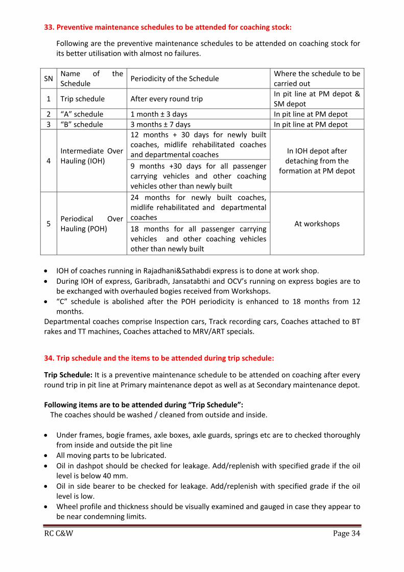
33. Preventive maintenance schedules to be attended for coaching stock:
Following are the preventive maintenance schedules to be attended on coaching stock for its better utilisation with almost no failures.
SN Name of the Schedule
Periodicity of the Schedule Where the schedule to be carried out
1 Trip schedule After every round trip In pit line at PM depot & SM depot
2 “A” schedule 1 month ± 3 days In pit line at PM depot
3 “B” schedule 3 months ± 7 days In pit line at PM depot
4 Intermediate Over Hauling (IOH)
12 months + 30 days for newly built coaches, midlife rehabilitated coaches and departmental coaches In IOH depot after
detaching from the formation at PM depot
9 months +30 days for all passenger carrying vehicles and other coaching vehicles other than newly built
5 Periodical Over Hauling (POH)
24 months for newly built coaches, midlife rehabilitated and departmental coaches
At workshops 18 months for all passenger carrying vehicles and other coaching vehicles other than newly built
IOH of coaches running in Rajadhani&Sathabdi express is to done at work shop.
During IOH of express, Garibradh, Jansatabthi and OCV’s running on express bogies are to be exchanged with overhauled bogies received from Workshops.
“C” schedule is abolished after the POH periodicity is enhanced to 18 months from 12 months.
Departmental coaches comprise Inspection cars, Track recording cars, Coaches attached to BT rakes and TT machines, Coaches attached to MRV/ART specials.
34. Trip schedule and the items to be attended during trip schedule:
Trip Schedule: It is a preventive maintenance schedule to be attended on coaching after every round trip in pit line at Primary maintenance depot as well as at Secondary maintenance depot. Following items are to be attended during “Trip Schedule”:
The coaches should be washed / cleaned from outside and inside.
Under frames, bogie frames, axle boxes, axle guards, springs etc are to checked thoroughly from inside and outside the pit line
All moving parts to be lubricated.
Oil in dashpot should be checked for leakage. Add/replenish with specified grade if the oil level is below 40 mm.
Oil in side bearer to be checked for leakage. Add/replenish with specified grade if the oil level is low.
Wheel profile and thickness should be visually examined and gauged in case they appear to be near condemning limits.

RC C&W Page 35
All the air brake components are to be checked for their proper functioning with RTR.
Alarm chain apparatus to be tested.
Brake power to be checked and adjusted so that the piston stroke is within the specified limit.
Check all the amenity fittings for its proper fitment and working.
35.The activities to be carried out during “A” schedule:
“A” schedule: It is preventive maintenance schedule to be attended on coaching stock in pit line at primary maintenance depot with periodicity of 1 month ± 3 days within the normal primary maintenance time.
Following items are to be attended during “A” schedule: All items of trip schedule. Intensive cleaning of coaches. Intensive cleaning of lavatory pans and commode with Vim or equivalent. Painting of commode chutes from inside and outside with black anti-corrosive paint after
scraping and thorough cleaning. Thorough flushing of tanks. Checking of water pipes, flush pipes, flushing cocks, push cocks etc, for ease of operation
and free flow of water. Thorough disinfect ion of all compartments. Thorough cleaning of chimneys of dining cars, buffet cars, tourist cars and inspection
carriages by wire brushes. Examination and replacement where necessary of brake gear pins, split pins, safety
loops/brackets and their securing devices. Examination for wear and replacement where necessary of brake hanger pins, brake blocks
and brake heads. Thorough inspection and repairs of draw gear. Thorough inspection and repairs of buffers. Checking and replenishing of oil in side bearers and dashpots. Thorough check and repairs of SLR doors for easy and smooth operation and correct
alignment of all wearing parts, loose screws etc.
36.The activities to be carried out during “B” schedule:
“B” schedule: It is preventive maintenance schedule to be attended on coaching stock in pit line at primary maintenance depot with periodicity of 3 months ± 7 days within the normal primary maintenance time.
Following items are to be attended during “B” schedule:
All items of ‘A’ Schedule.
Painting of lavatory from inside.
Thorough inspection and repair of brake gear components.
Examination overhauling and testing of alarm chain apparatus.
Testing and repairs of roof, especially the one laid with over and under lays of rubberoid sheet before monsoon begins.
Thorough checking of trough floor, turn under etc., from underneath for corrosion.
Touching up of painted/printed portion, if faded or soiled.

RC C&W Page 36
37. The procedure of IOH: Intermediate Over Hauling (IOH): It is preventive maintenance schedule to be attended on
coaching stock at Primary maintenance depot after detaching the coach from the formation in the IOH shed with a periodicity of 12 months for newly built coaches and departmental coaches and 9 months for all passenger coaching vehicles and other coaching vehicles with a grace period of 30 days.
IOH is also given on overdue POH coach before allowing in to service to ensure safety of the coach and the coach is allowed to service for a period of 3 months only. After expiry of 3 month the coach must be sent to POH repairs at work shop.
During IOH of a coach bogies are to replaced with the over hauled bogies received from work shop only. Following items are to be attended during IOH: a. Thorough repairs of running gear, brake gear and buffing gear b. Touching up damaged paint of coaches on outside as well as inside. c. Polishing of the polished surfaces. d. Thorough check of SAB e. Testing of BP and FP gauges with the master gauge. f. Thorough checking of train pipes under pressure of 2kg/sq cm to detect thin, corroded and
punctured pipes. g. Thorough cleaning and removal of dust, rust, dirt etc, accumulated at the pillars through
the turn under holes, with coir brush and compressed air. h. Thorough examination and repairs of upholstery, cushions, curtains etc. i. Thorough checking and full repairs of all window shutters, safety catches, safety latches,
staples and hasps of compartment, lavatory, body side and vestibule door step, locking gear etc., for ease of operation and safety.
j. Thorough checking and repairs of all damages of vinyl flooring of the compartment. k. Ultra sonic flaw detection test of axles, where facilities are available. l. Attention to corrosion of all ICF/BEML coaches as described below:
ii) C&W supervisors at PM depots should be fully familiar with the vulnerable areas of coaches for corrosion, viz., sole bars at doorways, lavatories and adjoining areas, Corridor sides – more so in case of SLRs’ which are used for fish, salt etc.
iii) Following schedule should be strictly followed for all ICF/BEML coaches in C&W depots.
iv) Pocket between sole bars and turn ender should be thoroughly cleaned through the inspection opening of the sole bars and inspected with the help of torch light or inspection lamps.
v) Drain holes provided in the trough floors should be kept clean and unclogged. If during the cleaning of these drain holes any accumulation of water is observed, the affected area should be very carefully inspected for possible corrosion.
vi) A register should be maintained of the primary maintenance coaches on the subject.

RC C&W Page 37
38. Gauges used during IOH:
The following gauges are to be used during IOH to ascertain the wear and tear and alignment of the bogie.
Trammeling gauge
Dash pot distance gauge
Knuckle profile gauge
Knuckle nose wear and stretch limit gauge.
Aligning wing limit gauge.
Vertical height aligning wing pocket and gauge arm gauge (Go gage)
Vertical height aligning wing pocket and guard arm gauge (No-Go gauge)
Buffer height gauge
Wheel distant gauge
Wheel profile gauge
Tyre defect gauge.
Comb gauge for flange thickness gauge The following gauge are used for checking “H” type CBC Knuckle nose wear and stretch limit gauge. Aligning wing limit gauge Vertical height aligning wing pocket and guard arm gauge (GO Gauge) Vertical height aligning wing pocket and guard arm gauge (NOGO Gauge) 39. Safety precautions to be taken at Work spot:
Use dry cotton cloths as per your sizes.
Wear shoes.
Use hand gloves while grinding, lifting heavy load, holding hot bodies.
Protect lines both sides by providing danger boards
Use nose mask where the dust is available.
Use helmets while working under gear
Use ear plugs, where then noise is more
Keep fire extinguishers, sand, water buckets.
Adopt proper methods
Display boards for failure/defective machinery.
Display ambulance phone no in the work places.
Put separate bins for new, reuse, and scrap materials
Use goggles and dark glass/welding shields while working with gas cutting&welding.
40.Upgraded materials to be provided for an express fit coach to enhance its POH periodicity
from 12months to 18 months:
To ensure proper utilisation and maximum availability of coaches for traffic utilisation to enhance the revenue without compromising on part of safety the POH periodicity of the coaches had been enhanced to 18 months from 12 months by providing the upgraded materials in the coaches during POH at work shop. CAMTECH, Gwalior issued guidelines for enhancement of POH periodicity of from 12 months to 18 months in January 2008. Vide these guidelines following items are to be provided on coaches during POH at workshop to the extent of 100% with new specifications issued by RDSO.

RC C&W Page 38
SN Item Description Upgraded Specification
1. PVC Flooring RDSO/2006/CG-12
2. Seat Upholstery Fire Retardant Vinyl Coated Fabric to Spec. No.
RDSO/2006/CG-16
3. Decorative Thermosetting
resin Bonded LP Sheet Fire Retardant Decorative Thermosetting resin
Bonded LP Sheet to Spec. No. C-8914
4. Cushioning Material for seats
and berths Densified Thermal Bonded Polyster Block (Recron) to Spec. No. C-K607/PU foam to spec. No. C-8914
5. Overhead water tanks Two piece Overhead water tank to ICF Drg. No.
ICF/SK-6-3-444 latest alteration
6. Brake Gear Bushes Composite brake Gear Bushes to Spec. No. C-
K605/C-K307/C-K510
7. Upper and Lower washers
for primary suspension High capacity Hytrel washers to spec. No. C-K409
(Rev.1)
8. Silent block for anchor link Injection moulded silent block for anchor link to
spec. No. RDSO/2006/CG-5
41.Salient features of ICF coach:
Salient features of ICF Coach: All welded, stressed skin integral tubular construction adopted. Provided with Anti telescopic body fitted with distraction tube inside the buffers
with trough flooring. Lavatories are provided on either ends near doorways. Self aligning spherical roller bearings are used to minimize friction resistance
and easy hauling with pendulum type axle box. The bogie incorporates primary and secondary suspension arranged in series. The axle boxes are guided by axle guides and wear and tear of axle boxes are
eliminated with hydraulic dashpot arrangement provided for primary suspension.
The secondary suspension is provided with bolster springs and double acting telescopic shock absorbers.
Silent blocks are fitted in centre pivot and anchor links to reduce noise. Unsprung mass is reduced by 18.5% as compared to IRS bogie by reducing wheel
sizes. The bogie frame is completely welded construction with flats and plates. Modern welding technologies are adopted for welding due to which weight of
bogie is reduced by 25% when compared to IRS. Longer bolster suspension links to ensure better riding qualities. The links are
inclined at an angle of 70 away from the coach vertically. In these coaches pay load is not shared by trough floor. Pressed “Z” sections are used for sole bar

RC C&W Page 39
42. Features made on ICF coach for “Anti telescopic”
Initially railway carriages are wooden bodied. Wooden body is fixed on to the steel under frame. During accidents these wooden bodies are prone for more damages by piercing one coach in to another due to the weaker construction which is called telescopic nature. This telescopic nature of wooden coaches had led to heavy causalities during accidents. In order reduce the causalities concept of anti telescopic body was developed by using all metal, all welded and light weight materials.
Construction features which made an ICF coach shell “anti telescopic”: The shell of ICF coach consists of pressed steel sections welded together with sheet
covering. The skeleton shell consists of a series of hoops each consisting of floor cross beams, body side pillars and roof carlines. The sole bar, waist rail, cant rail and roof purlines held these hoops together. This is covered by roof sheet on top, side panels on sides and corrugated trough floor. The corrugated trough floor offer considerable resistance to longitudinal crushing loads. On each end specially designed head stock with compression/destruction tubes are welded. These tubes during collision get deformed absorbing most of the energy.
Body bolsters are welded on bottom side of trough floor. The coach ends consists 4 box section stanchions transversely connected by “Z” section stiffeners and are welded to head stock. During collisions impact is first absorbed largely by end stanchions. The residual shock is absorbed by deformation of destruction/compression tubes.
The reduction in tare weight of these coaches obtained by using light weight, high strength, and corrosion resistant CORTON steel and by use of light weight alloy fittings. The concept of stressed skin also helps achieving light weight of coaches. 1.6 mm thick sheet used on roof and 2 mm thick used on side wall and end wall.
The Integral Shell behaves as a hollow tube offering maximum resistance towards telescoping in case of end wall collision. The head stock consists of main and auxiliary head stock connected by a rigid buffer beam which transmits all the buffing forces to the under frame.
All the above features made an ICF coach “anti telescopic”.
44. Transmission of “tractive force, braking force and load transmission” in ICF coach.
Bogie: it is a general term used for the assembly of all suspension parts, which toghter support the coach body at the two ends. It includes the structural frame, wheels, axles and bearings, suspension links, springs etc. ICF all coil bogie: the bogie frame is built from “I” section fabricated by welding. Axles are located on the bogie by telescopic dashpot and axle guide assemblies with wheel base of 2896mm. helical springs are used in both primary and secondary suspension stages. The axle guide device provides viscous damping across primary springs while hydraulic dampers are provided across secondary suspension stage. Dampers are protected against misalignment by resilient fittings. Isolation of vibration is effected by rubber padsin primary suspension. Weight of coach body is transmitted to its bogie by side bearers pitched 1600mm apart. Side bearer consists of lubricated metal slides immersed in oil bath. No vertical weight transfer is affected through bogie pivot, and pivot acts merely as a center of rotation and serve to transmit tractive and brake force only.

RC C&W Page 40
Transmission of tractive forces: The sequence of transmission of tractive force is follows. Coupling – Head stock – under frame – Body bolster – Center pivot – Bogie bolster – Anchor links – Bogie frame – Axle guides – Axle box – Axle – wheels. Transmission of braking forces: Transmission of braking force is reverse of that of tractive force. Transmission of load: Coach body – Side bearers – Bolster – Bolster coil springs – Lower Spring Plank – Stirrup links – Bogie side frame – Axle box Coil Springs – Axle box Wings – Axle Box – Bearing – Axle – Wheels – Rails. 45.Salient feature of LHB coach: The salient features of LHB coaches are
a. These coaches are longer by 2.2 meters than the ICF coaches and hence more number of passengers can be accommodated in a given coach. As the length of the coach is longer the number of coaches required to form a formation is reduced and hence overall cost of maintenance becomes less.
b. These coaches are fitted with Axle Mounted Disc brakes to have an effective brake power to stop the train within the emergency braking distance. As the brake forces are acting on the Discs which are mounted on the Axles, the wear on the wheel tread caused due to tread brake is eliminated and hence the life of the wheels are considerably increased.
c. These coaches are fitted with Wheel slide protection device to prevent the wheel from getting skid. Due to various reasons it is possible for any one of the wheel to have lesser speed when compared to the other three wheels and in such a case it releases the air from the brake cylinder of the affected wheel automatically to prevent the wheels from getting skidding.
d. These coaches are fitted with Brake accelerator in the Brake pipe to bring BP pressure to zero during emergency brake application. The brake accelerator connects the Brake pipe with exhaust during emergency application to facilitate faster releasing of air from the brake pipe.
e. These coaches are provided with FIAT bogies, which are designed to run at a speed of 160 KMPH.
f. These coaches are fitted with Controlled discharge Toilet system designed to discharge the human waste when the speed reaches above 30 KMPH after completion of 5 flushing. The objective of this toilet system is to keep the station premises clean and hygienic.
g. These are fitted with tight lock AAR centre buffer coupler with anti-climbing feature to prevent the climbing of one coach over another in case of accidents.
h. The wheelbase of Bogie is 2560 mm. i. These coaches are fitted with earthing device to prevent damages to the Roller bearings. j. These coaches are fitted with roof mounted AC package units. k. The following equipments are operated by electronically operated control system
(Microprocessor) Wheel slide protection device.
Controlled discharge toilet system.
Water pumping device.
Roof mounted AC package units
l. The riding index of LHB coach is 2.75 when compared to 3.25 in case of ICF Coaches m. The passenger emergency alarms signal devices are provided inside passenger
compartment. This is to avoid operation of PEASD by unauthorized persons from outside. There is no mechanical linkage like a chain and this handle directly operates the PEASD valve for venting the brake pipe pressure.

RC C&W Page 41
46. Salient features of Duranto express Hybrid coach It is hybrid coach manufactured as per the design of ICF bogie and shell with features of LHB shell.
a. For the first time non – AC sleeper coaches are introduced in Non – Stop trains. b. Construction of shell is similar to that of ICF coach. c. Instead of CARTON steel, stainless steel is used for construction, which resulted in
reduction of tare weight by 2 Tonnes. d. Length of the coach increased to accommodate more No of passenger coaches.
No of berths in 3 – tire AC (ACCN) - 72 nos. No of berths in 3 tire Non - AC (SCN) - 78 nos.
e. All the coaches are provided with Auto closing sliding type vestibule door which will stop spreading of the fire in case of fire accident.
f. All the coaches are provided with CDTS for comfort of passengers. g. Bogies is similar to ICF all coil bogie excepting that in secondary suspension air springs is
provided instead of coil springs (Bolster springs) for better riding comfort which resulted in reduction of ride index to 2.5 against 3.5 in ICF all coil bogie.
h. Extra B.P / F.P hose pipes with cut off angle cocks are provided on either ends of coach so that in case of any defect occurred on air hose the corresponding angle cocks can be closed and Air hose can be used, thus maintaining the punctuality.
i. In case of isolation of Air spring even on one bogie / Coach entire train has to run with a speed not more than 60 KMPH up to destination.
j. Modification for the fitment of Air spring. a. Bogie frame and suspension: Air spring has been installed in secondary stage
replacing steel coil springs. A fixed lower spring beam (As cradle) to accommodate the air spring has been provided on bogie bolster. A lateral hydraulic damper and lateral bump stop have been provided at secondary stage.
b. Bogie bolster: Provision made for air inlet to air spring. 40 Lt additional reservoirs connected to each air spring. Duplex check valve is provided. Due to the above modifications BSS hangers, Equalizing stays are eliminated.
47. Necessity of introduction of Air springs in Indian Railways: In suburban trains like DEMU, the number of passengers entraining (Super Dense Crush Load) in to the coach cannot be controlled and hence the payload of the coach increases from 18 tons to 34 tons. This abnormal increase of payload reduces the Riding Clearances between the Coaches and Wayside platforms and also reduces buffer height resulting in severe hitting of coach on the plat forms. Due to the Super Dense Crush Load the bolster springs become solid, which in turn damages / breaks the Coil springs resulting in discomfort to the passengers.
So to overcome the above problems Air Suspension (Air springs) is introduced in the secondary suspension to maintain a constant buffer height irrespective of loaded conditions by varying the pressure of air inside the air spring.
Due to its excellent riding index the air springs are introduced in Duronto express.

RC C&W Page 42
48.Working of “Air spring”: Air spring is a rubber bellow containing pressurized compressed air with an emergency rubber spring providing various suspension characteristics to maintain a constant Buffer height irrespective of the loaded condition. Air spring main parts
I. Emergency spring II. Leveling valve
III. Adjustable screw rod IV. Duplex Valve V. Main Air Reservoir
VI. Auxiliary Reservoir VII. Isolating Cock

RC C&W Page 43
Air suspension is a suspension where properties of air are used for cushioning effect (springiness). Enclosed pressurized air in a pre – defined chamber called air springs, made up of rubber bellow & emergency rubber spring, provides various suspension characteristics including damping. Air springs are height – controlled load leveling suspension devices. With changing loads, air springs react initially by changing the distance between air springs support and vehicle body. The leveling valve is in turn actuated, either taking the compressed air pressure to the air spring or releasing air pressure from it to the atmosphere. This process continuous until the original height is restored. This mechanism ensures a constant floor height on coaches provided with air springs, irrespective of loads.
49. Comparison of air springs with coil springs and advantages and characteristics of air springs.
Unlike steel springs, air springs retain their height under changing loads. The low natural frequency of air spring suspension remains virtually constant.
In case of coil spring, deflection is proportionate to the load, therefore, under high payload situation, space constraint becomes critical, leading to the use of stiffer springs resulting in unsatisfactory ride behavior and reduced speed potential.
Air springs through their control mechanism offer a load proportionate stiffness, constant floor height and better ride behavior with higher speed.

RC C&W Page 44
Advantages of Air springs:
o Capable to sustain Super Dense Crush Load of suburban traffic at high speeds. o It maintains a Constant floor height of coach. o It facilitates excellent riding comfort with riding index of 2.5. o Safe running due to the excellent Air Damping. o Low design height. o Unusual noise emitted due to hitting of coaches on the plat forms is eliminated. o The Stirrup links, Coil springs and equalizing stays are eliminated and therefore easy
to maintenance. Characteristics:
Soft flexible characteristics in vertical direction achieved by compression of air.
Excellent lateral spring characteristics achieved by variation in effective area in lateral direction.
Avoids excess air consumption due to instantaneous modes of oscillation / change in pressure achieved by delayed reaction in leveling valve.
50. Parts of “Air Spring” and their functions briefly:
The leveling valve is fitted with Top bolster and is designed to move up and down along with bolster. Under normal condition, it is designed to take LAP position when the actual buffer height is equal to the required buffer height.
The function of leveling valve is to connect the main reservoir with the air spring to admit more pressure in to the Air spring, whenever the actual buffer height is less than the required buffer height due to abnormal increase in the Pay load (Super Dense Crush load).

RC C&W Page 45
It also connects the air springs with exhaust to release the excess air from air spring, whenever the actual buffer height is more than required buffer height due to reduction in the Pay load after detraining of passengers from the coach
. Installation lever: It is fitted between the leveling valve and bottom of the bogie frame. The function of installation lever is to operate the leveling valve automatically by moving the handle of the leveling valve up and down according to the condition of the load. The up and down movement of handle of leveling valve admits the compressed air in to the Air spring or releases the compressed air from the air spring through leveling valve in proportion to the pay load of the coach. Duplex Valve: It is a double check valve provided between the Air springs of the same bogie .It operates with a Pressure differential of 1.5 bar. Basically it comprises of two check valves side by side, arranged so that air can flow in either direction whenever the air pressure differential exceeds the pre-set value of 1.5 bar. Whenever a burst of air spring occurs on one side, this valve will ensure that no severe tilt or twist occurs during movement of the coach.
Both the check valves of Duplex valve remains closed, if the pressure between the two springs is within 1.5 bars.
When the differential air pressure exceeds the preset value, the air at higher pressure overcomes the spring pressure and flows to the lower pressure via the check valve. The flow continues till the differential reaches the preset value.
In case of burst of Air Spring, the air leaks to atmosphere. Due to high-pressure differential, the Duplex check valve releases the air from the intact air spring through burst air spring. Thus complete coach will gradually come down and rest on the emergency rubber springs.
Auxiliary reservoir:It isfitted with the Air spring. The capacity of this reservoir is 40 Ltrs. There is an orifice kept between air spring and additional reservoir. It acts as an Air damper to overcome vertical and lateral oscillations so as to increase the riding comfort.
Main reservoir: The capacity of the main reservoir is 150 ltrs and it is exclusively used for feeding the compressed air in to the Air Spring. Emergency spring: The function of emergency spring is to support the top bolster to prevent tilt of coaches whenever the Air spring burst.
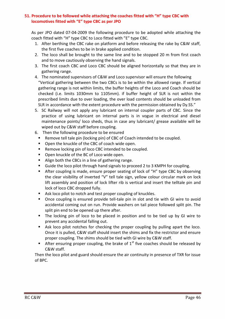
RC C&W Page 46
51. Procedure to be followed while attaching the coaches fitted with “H” type CBC with locomotives fitted with “E” type CBC as per JPO As per JPO dated 07-04-2009 the following procedure to be adopted while attaching the coach fitted with “H” type CBC to Loco fitted with ”E” type CBC.
1. After berthing the CBC rake on platform and before releasing the rake by C&W staff, the first five coaches to be in brake applied condition.
2. The loco shall be brought to the same line and to be stopped 20 m from first coach and to move cautiously observing the hand signals.
3. The first coach CBC and Loco CBC should be aligned horizontally so that they are in gathering range.
4. The nominated supervisors of C&W and Loco supervisor will ensure the following “Vertical gathering between the two CBCs is to be within the allowed range. If vertical gathering range is not within limits, the buffer heights of the Loco and Coach should be checked (i.e. limits 1030mm to 1105mm). if buffer height of SLR is not within the prescribed limits due to over loading, the over load contents should be unloaded from SLR in accordance with the extent procedure with the permission obtained by Dy.SS.”
5. SC Railway will not apply any lubricant on internal coupler parts of CBC. Since the practice of using lubricant on internal parts is in vogue in electrical and diesel maintenance points/ loco sheds, thus in case any lubricant/ grease available will be wiped out by C&W staff before coupling.
6. Then the following procedure to be ensured Remove tell tale pin (locking pin) of CBC of Coach intended to be coupled. Open the knuckle of the CBC of coach wide open. Remove locking pin of loco CBC intended to be coupled. Open knuckle of the BC of Loco wide open. Align both the CBCs in a line of gathering range. Guide the loco pilot through hand signals to proceed 2 to 3 KMPH for coupling. After coupling is made, ensure proper seating of lock of “H” type CBC by observing
the clear visibility of inverted “V” tell tale sign, yellow colour circular mark on lock lift assembly and position of lock lifter rib is vertical and insert the telltale pin and lock of loco CBC dropped fully.
Ask loco pilot to notch and test proper coupling of knuckles. Once coupling is ensured provide tell-tale pin in slot and tie with GI wire to avoid
accidental coming out on run. Provide washers on tail piece followed split pin. The split pin end to be opened up there after.
The locking pin of loco to be placed in position and to be tied up by GI wire to prevent any accidental falling out.
Ask loco pilot notches for checking the proper coupling by pulling apart the loco. Once it is pulled, C&W staff should insert the shims and fix the restrictor and ensure proper coupling. The shims should be tied with GI wire by C&W staff.
After ensuring proper coupling, the brake of 1st five coaches should be released by C&W staff.
Then the loco pilot and guard should ensure the air continuity in presence of TXR for issue of BPC.

RC C&W Page 47
52. Different amenity and safety fittings in coaches:
The different amenity fittings in a coach are:
The responsibility of a supervisor is to ensure that all the fittings provided for the use of passengers are to be in correct and good condition. Else, this invites public complaints. 53. Various activities undertaken by Indian Railways to improve thecondition of passenger Coaches: Indian railways is the largest network under taking transportation of Passengers and goods. Of late importance is given to the safety and aesthetics of coaching stock. The various modifications and activities under taken to improve the condition of Rolling stock are.
Provision of Air brakes and disc brakes Introduction of Composite brake blocks. Intensive cleaning of Coaches. Attention to Cleanliness on enroute trains. Steam cleaning of Pantry cars. Periodic Disinfection and pest control treatment. Attention of Zero missing of amenity fitting. Provision of shock absorbers in Primary suspension. Introduction of CDTS Introduction of Air springs Introduction of GPS boards
Main Door Door handle
Hand rails Latches to close the door
Seat Berth
Berth Chain Window
Window bars Roof ventilator
Coat hook Light and fan
Alarm chain Armrest, tea/snack table
Foot steps to climb to upper berth Back rest with locking provision for the side berths
Glass and Venetian shutters with lock provision
Provision of securing arrangement below the seat for the luggage
Luggage rack in case of general compartments
Washbasin on either ends of the coach with mirror and mirror stand
Provision of night lamp for sleeper and upper class coaches
Vestibule with door and fall plate arrangement secured with pin
Provision of reading lamp in AC and First class coaches
Provision of Coupe system in First class coaches with door
Curtains for having privacy in AC class
Provision of 3 Indian style and 1 western style toilet with the following fittings
Door with turn over latch and locking arrangement
Squatting pan/Commode with commode lid and cover
Flushing cock with FO handle, FO pipe and fish tail
Provision of mirror, mirror stand and wash basin
Windows with Frosted glass for light and ventilation
Provision of push cock/ Jason cocks 2 nos
Mugs in the upper class coaches Shower arrangement in first class coaches
Fan and Alarm chain arrangement in Upper class coaches
Air freshener in upper class coaches

RC C&W Page 48
54. List out public complaints pertaining to the C&W branch and the remedial measures to be taken to avoid the complaints:
SN Cause Remedial measure
1. Non-availability of water in
coaches
Ensure full watering of all coaches at originating stations and enroute at nominated watering stations.
2. Non-cleaning of coach toilets, wash basins, coach interior.
Ensure intensive cleaning of toilets during PM/SM attention and proper interior cleaning of coaches. Enroute cleaning of toilets to be done at nominated stations.
3. Existence of cockroaches,
insects, rats, etc. Ensure thorough periodic disinfestations of coaches.
4. Improper condition of berths,
seats, snack table, door closers etc.
Ensure through attention to berths, seats during ‘C’ schedule maintenance and PM/SM attention. Proper attention to be paid to the reclining mechanism of CZAC coaches, snack tables, door closures during PM/SM attention.
5. Dirty condition of AC Coach
curtains. Ensure periodic washing of curtains of AC Coaches.
6. Water leakage through windows Ensure proper ceiling is provided to the window glasses of AC Coaches during the Replacement in sick line/shops.
7. Soiled Linen Ensure proper washed Linen in sufficient quantity available in the coach at originating stations.
55.Types of couplers available on Indian Railways? Give their limits of usage: The different types of couplers and their usage are,
SN Type of coupling Usage
1. Screw coupling
IRS Type 4-Wheeler wagons
Enhanced coupling All Coaching stock
2. Centre Buffer Coupler
AAR type NHT 8 Wheeler goods stock Vacuum braked stock
AAR type HT 8 Wheeler goods stock Air braked stock
Alliance II type 4 Wheeler goods stock
3. Automatic buffer Coupler MG stock
4. Schaku Coupler DEMU / EMU
5. AAR Modified LHB coaches
6. Slack free Coupler BLC Wagons
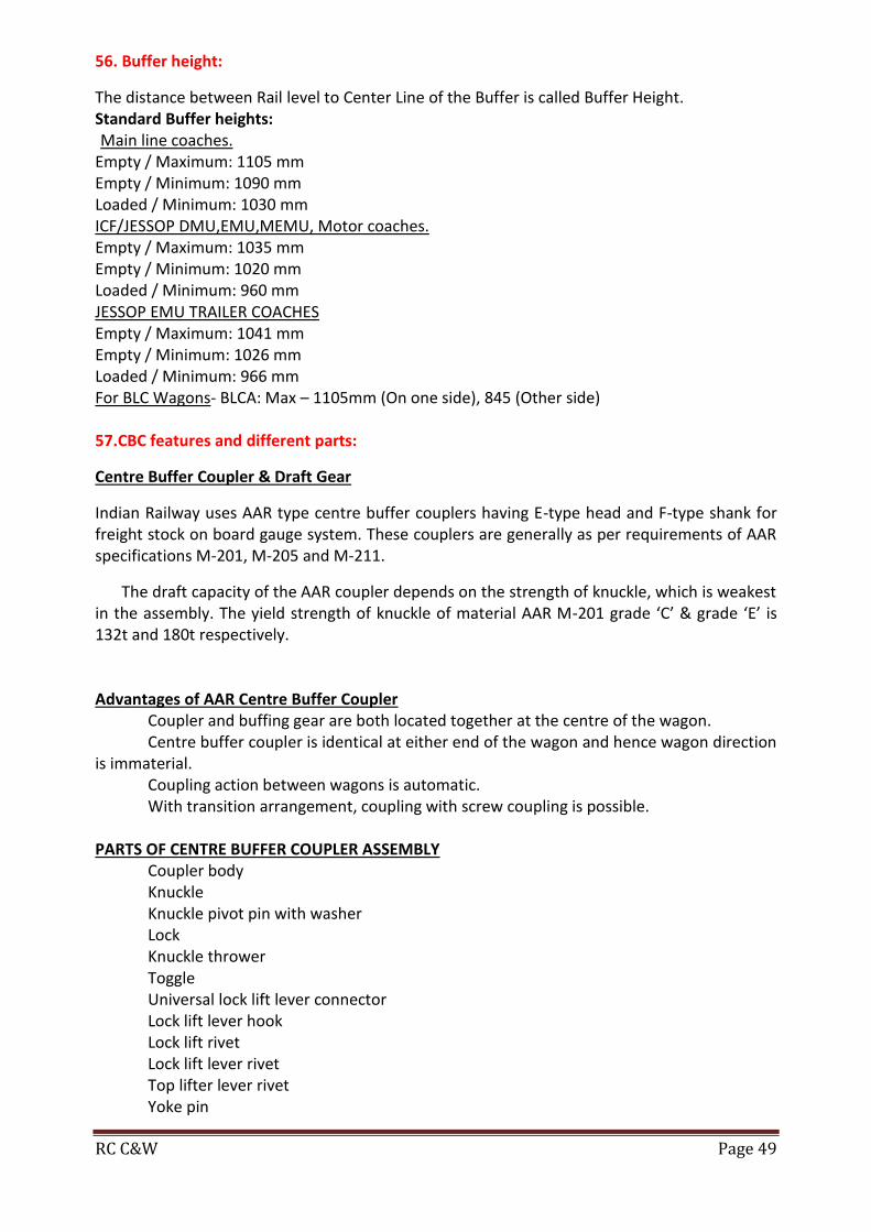
RC C&W Page 49
56. Buffer height:
The distance between Rail level to Center Line of the Buffer is called Buffer Height. Standard Buffer heights: Main line coaches.
Empty / Maximum: 1105 mm Empty / Minimum: 1090 mm Loaded / Minimum: 1030 mm ICF/JESSOP DMU,EMU,MEMU, Motor coaches. Empty / Maximum: 1035 mm Empty / Minimum: 1020 mm Loaded / Minimum: 960 mm JESSOP EMU TRAILER COACHES Empty / Maximum: 1041 mm Empty / Minimum: 1026 mm Loaded / Minimum: 966 mm For BLC Wagons- BLCA: Max – 1105mm (On one side), 845 (Other side) 57.CBC features and different parts:
Centre Buffer Coupler & Draft Gear
Indian Railway uses AAR type centre buffer couplers having E-type head and F-type shank for freight stock on board gauge system. These couplers are generally as per requirements of AAR specifications M-201, M-205 and M-211.
The draft capacity of the AAR coupler depends on the strength of knuckle, which is weakest in the assembly. The yield strength of knuckle of material AAR M-201 grade ‘C’ & grade ‘E’ is 132t and 180t respectively. Advantages of AAR Centre Buffer Coupler
Coupler and buffing gear are both located together at the centre of the wagon. Centre buffer coupler is identical at either end of the wagon and hence wagon direction
is immaterial. Coupling action between wagons is automatic. With transition arrangement, coupling with screw coupling is possible.
PARTS OF CENTRE BUFFER COUPLER ASSEMBLY
Coupler body Knuckle Knuckle pivot pin with washer Lock Knuckle thrower Toggle Universal lock lift lever connector Lock lift lever hook Lock lift rivet Lock lift lever rivet Top lifter lever rivet Yoke pin

RC C&W Page 50
Yoke Yoke pin support Striker casting Sticker casting war please Shank wear plate Yoke support plate Draft gear arrangement with front follower Safety bracket gear arrangement Uncoupling gear arrangement Back stop Clevis for transition type coupler only Screw coupling for transition type coupler only Clevis pin for transition type coupler only
58. Procedure of Anti Creep Mechanism in CBC of goods stock:
Anti Creep Mechanism: This is an inbuilt mechanism provided for all the CBCs’ to prevent automatic Lifting of lock on run in order to prevent train parting. The Anti-creep mechanism in AAR coupler is provided between the Toggle and the coupler body. It is in the form of ledge on the toggle and in the form of lug in the coupler Body. Whenever the lock gets lifted, it also lifts the lock lift assembly along with it. As the toggle moves up vertically, its anti-creep ledge, which is just below the Anti-creep lug of the coupler body hits against this anti-creep lug, thereby prevents the further lifting of lock. The procedure for checking anti creep mechanism: a. Close the knuckle. b. Insert a bar between the lock and the knuckle tail shelf and lift the lock upwards and at the
same time push the lug rearward by inserting a screw driver between the coupler body and the front of the lock hole.
c. If the lock can be raised enough to permit the opening of the knuckle, the anti-creep mechanism is defective.
d. Replace the lock lift assembly. (Toggle, Lock lift lever and Lock lift lever hook). e. Check again. f. Even after replacing the above, if the lock can be raised, the Anti-creep mechanism is found
defective due to excessive wear on the lug of the coupler body. g. In such a case, replace the coupler body.
59. Types of bearings and parts of tapered roller bearing: There are three types of bearings:
CTRB (Cartridge tapered roller bearing) is used in BOXN and BCN.
Cylindrical Roller Bearing: is used for BOXC
Spherical Roller Bearing: is used for ICF coaches. The parts of tapered roller bearing are: 1) Outer Race. 2) Inner Race. 3) Rollers. 4) Cage. 5) Seal. 6) spacer. 7) Backing Ring. 8) End Cap. 9) Cap Screw 10) Locking plate 11) Grease seal 12) Wear rings.

RC C&W Page 51
60. Types of axles in IR, parts and axle defects: Axle is a shaft made out of forging with a special contour to fix wheel disc and roller bearings on either sides. It is a very important component in safe running of train. The different types of axles used in Indian railways are:
13T Axles used on BG non-AC coaches.
16.25T Axles used on BG AC coaches.
20.3 T Axles used on BG DHMU/EMU motor car and BG UIC wagons.
16.3T BG four wheeler wagons
22.9T Axles used on BG CASNUB bogies.
25T Axles used on BG CASNUB bogies of latest wagons. Parts of axle: 1) Journal 2) Shoulder 3) Wheel seat 4) Axle centre Different Axle defects are:
1. Bent Axle. 2. Grooved / Notched Axle. 3. Loose Axle. 4. Dent marks on the Axle.
61. Empty/Load box andit’s working: It is a mechanical device, which enables to provide two different leverage ratios to the
brake rigging of the wagon for the empty and the loaded conditions
The braking force required to stop a train within the permissible stopping distance depends on the load of the train.
As the load increases more brake power is required, and as the load decreases less brake power is required to stop the train.
So the brake power should be increased or decreased according to the requirement by changing the brake leverage ratio. To enable this, the ‘EMPTY-LOAD BOX’ device is provided on wagons, in between the brake cylinder and the brake blocks in the brake rigging.
The position of the change over lever of the EL box is to be set to ensure correct brake power according to the gross weight, as given below.
Less than 42.5 tonnes – in empty position 42.5 tonnes &above - in loaded position

RC C&W Page 52
Brake Rigging:-
The LOAD-EMPTY device consists of two horizontal levers (one live and the dead) which are connected by means of empty and load tie rods.
When the handle is kept in empty position, the empty tie rod is connected with the system and in turn provides low leverage ratio, thereby gives lesser brake force.
When the handle is kept in load position, the load tie rod is connected with the system and in turn provides high leverage ratio, there by gives higher brake force as required.
62. Types of SABs available in rolling stock:
SAB Stands for SVENSKA AKTIE BOLAGOT BROMSRegulator. This is a mechanical device
provided in the brake rigging, forms part of the pull rod, for the automatic adjustment of the clearance between the brake blocks and wheels/ slack in the brake rigging. This automatically operates to shorten or lengthen the length of the pull rod, to adjust the excess or less slack in the brake rigging or brake block clearance.
This helps to maintain the clearance between the brake block and the wheels to a pre-determined constant value always, thereby maintaining the piston stroke of the brake cylinder constant. This, in turn, always maintains constant brake power for the wagon or coach on the run. There are three types of SABs
1. DRV 450 (Used on Coaching Stock) 2. DRV 600 (Used on Air Brake goods stock) 3. DRV 750 (Used on BCNHL / BOXN HL Wagons)
“D”Means “Double Acting” “R” Means “Rapid” “V” Means “Verificative” 450 / 600 / 750 indicate capacity to lengthen / shorten the SAB pull rod.
63. “A” dimension and its significance
This is the distance between the slack adjuster barrel and the control rod head, measured when the brake is in fully released condition.
This is called as ‘Control Dimension’, because this is the pre-determined dimension, according to which the slack adjuster pays-out /takes-up the slack in the brake rigging.
This dimension is constant once set it will not change in service due to wear and tare of brake blocks / Wheels.
This dimension determines the correct piston stroke of the cylinder. The dimensions of different rolling stock are as follows.
The control rods ‘A’ dimension for Different Rolling stock are given below:
a) Coaching stock 16+ 2/-0mm for 13 T bogie stock 22+ 2/-0 mm for 16.25 T bogie stock
b) Goods Stock 50 mm for VB Stock 70 mm for Air brake stock 27 mm for BOBRN

RC C&W Page 53
64. “e” dimension and its significance:
This is the distance between the end of the protective sleeve of the screw and the grooved mark on the screw rod when the screw rod is in fully released This indicates the total capacity of the slack adjuster available for the adjustment of the brake rigging clearance. This ‘e’ dimension will be as follows.
375 ± 25 mm for coaching stock, 555 ± 20 mm for goods stock, 560 + 25mm for BCNHL wagons This dimension will decrease as wear takes place on brake blocks, wheels, brake gear pins and bushes due to brake applications. This will be the maximum when
All Brake blocks are new,
All the brake gear pins and buses are new,
All the wheels are at maximum diameter, or As the ‘e’ dimension decreases and reaches to the minimum due to the wear on the wheel tread, which cannot be made up (worn out brake blocks, brake gear pins and bushes can be replaced with new ones), manual adjustment shall be done according to the worn out wheel diameter, on the adjusting link of the bogie. This will ensure that sufficient capacity of ‘e’ dimension will be again made available for subsequent adjustments.
Significance: SAB “e” Dimension indicates maximum take up of slackness in brake rigging by the SAB. 65. Different types of tools and plants used by C&W staff during train examination:
DIFFERENT TYPES OF TOOLS DIFFERENT TYPES OF PLANTS
1.Hammer 2.Tommy Bar 3.Pin Punch. 4.Chisel 5.Pipe Wrench 6.Different sizes of Spanners 7.Different type of gauges: a.Gauge for Buffer Height b.Checking gauge for Bent Link Screw Coupling c.Flat gauge for Draw Hook & Draw Bar d.Checking gauge for SAB 'A' Dimension for 13T Bogie (NONAC) e.Checking gauge for SAB 'A' Dimension for 16.25T Bogie (AC) f. Wheel Flange Thickness gauge g. Flat Profile gauge for Draw Bar seating of Draft Key h.Checking gauge for Axle Guide i.Checking gauge for Axle Guide Bush j.Checking gauge for Axle Assembly k.Flat gauge for Draft Key Slot of Draw Hook l.Tyre Defect Gauge m.Wheel distance Gauge n.Wheel dia measuring gauge (caliber)
1.Air Compressor 2.Rake Test Rig. 3.Single Car Test Rig. 4.Car washing plant. 5.Dry and Wet VacuumCleaner. 6.Steam cleaning jet. 7.Stair Cleaner. 8.High pressure Static Jet. 9.High Pressure Cold Water Jet. 10.Welding Machine.

RC C&W Page 54
66.Rolling stock registers to be maintained by a C&W Supervisor: The following documents are to be maintained by C&W Supervisor -
RS1 Overall sick detention register
RS2 Repacking register
RS3 Oiling register
RS4 Vacuum brake maintenance register
RS5 Vacuum register for incoming train
RS6 Brake power certificate
RS7 Train examiner diary
RS8 Register for hot box
RS9 Wheel register
RS10 Sending to shops of coaching and wagon stock
RS11 Register of damage and deficiencies of rake
RS12 Register of wagons tested for leaking.
RS13 Register of fire extinguishers
RS14 Register of portable telephone in brake van
RS.15 Register of train examiner book (DVR)
RS.16 Sick memo book
RS-17 Fit memo book
RS.18 Report of damages caused by theft, mischief etc.
RS.19 Register of coaching treated with section code
RS.20 Tank wagon register
RS.21 sick label register
RS.22 Damage/deficiencies noted label
RS.23 Abstract of repacking and oiling of boxes
RS.24 Application for CME for condemning of rolling stock
RS.36 Rolling stock laid up and waiting for materials
RS.61 Theft of mechanical fittings of coaching stock
RS.65 Accident train parting register
RS.68 Label damage not to go
RS.69 Details of rake maintenance
RS.70 Hotbox report
RS.71 Coach maintenance history card
RS.72 Trip schedule card
RS.73 “B”schedules card
RS.74 “A”schedule card etc. 67. CC+8+2& Modifications to be done to enhance CC+8+2:
CC+8+2: It indicates the increase in loading capacity of a wagon above the normal Carrying Capacity stenciled on it (i.e. Carrying capacity +8 Tonnes +2 Tonnes) For example CC of BOXN wagon is 58 tonnes enhanced to 58+8+2=68 tonnes. Similarly for BCNA wagon CC is 57 tonnes enhanced to 57+8+2 tonnes. The existing BOXN and BCN wagons are provided with suspension system designed for 20.3t axle load i.e. each axle can carry a load of 20.3t and 4 axles can carry 20.3X4=81.2t which is equal to gross weight of BCN & BOXN wagons.

RC C&W Page 55
The spring arrangement for 22.9t and 20.3t axle load is given in the table for all types of CASNUB bogies except CASNUB 22HS which already consists of 7 outer springs.
BOGIES SPRINGS Axle load
22.9 T 20.3T
CASNUB22W,WR, WM, NL, NLM, NLB
OUTER - A 7 6
INNER - B 5 4
SNUBBER - C 2 2
For CASNUB 22HS the spring arrangement is
Axle load Outer Inner Snubber
20.3t 7 6 2
22.9t 7 7 2
68. Accidents and Classification: Accident is any occurrence which affects or may effect the safety of railways, its engine, rolling stock, permanent way, works, passengers, servants or other or which interferes with the normal working of railway is termed as an accident. Accidents are classified as under.
1) “A” Class - Collisions. 2) “B” Class - Fire on trains. 3) “C” Class - Train running into road traffic. 4) “D” class - Derailments. 5) “E” Class - Other train and trolley accidents. 6) “F” Class - averted collisions. 7) “G” class - breach of block rules.

RC C&W Page 56
8) “H” Class - Train passing signal at danger. 9) “J” Class - Failure of engine or rolling stock. 10) “K” Class - Failure of permanent way. 11) “L” Class - Failure of electrical equipment. 12) “M” Class - Failure of S&T equipment. 13) “N” Class - Train wrecking. 14) “P” Class - Causalities like cattle run over etc.., 15) “Q” Class - unusual incidents like murder, suicide etc..,. 16) “R” Class - miscellaneous.
Accidents take place due to one factor or combination of factor listed below: 1. Defects in Rolling stock. 2. Defects in permanent way. 3. Operational failure. 4. Excessive speed. 5. Obstruction on track. 6. Defects in signal and interlock. 7. Irregular, excessive or uneven loading. 8. Sabotage by Miscreants. 9. Natural calamity. 10. Human failure.
69. Siren codes for Break down specials and their dispatch times:
Siren codes during accident alert.
Siren code Description
2 Long When an accident occurs in loco shed or traffic yard
3 Long When an accident occurs at out station but main line is clear
3 Long & 1 short When an accident occurs at out station main line is clear and ART to be turned out with medical van(ARMV)
4 Long When accident occurs at out station, main line blocked and ART to be turned out without medical van.
4 Long & 1 short When accident occurs at out station, main line blocked and ART to be turned out with medical van.
Duration of long hooter shall be 30seconds and that of short is 5 seconds. Dispatch times of ART and ARMV: ART should start in 30 minutes during day and 45 minutes during night from the time of
reception of information. ARMV should start within 15 minutes during day and night for direct dispatch and 20
minutes for indirect dispatch from the time of reception of information. ARMV can be moved by utilizing any train engine of any scheduled train available at
that time. 70. Classification of ART Break down specials on Indian Railways and their composition
Break down special is a train, meant for attending emergencies like accidents and disasters etc. on railways comprising of HRD and HRE equipment. Break down specials are classified as ART’s, ARMV’s and 140T BD crane specials. Classification of “ART”

RC C&W Page 57
ART’s are classified as “A” class, “B” class, “C” class “A”Class ART consists of
I. 140T diesel crane with match truck. II. One equipment van containing HRE, Generator, Compressor etc..,
III. Two staff rest van including kitchen car. IV. One BFR containing Engg. equipment. V. One BFR containing electrical and other equipment.
VI. One van containing OHE, S&T, Electrical equipment. “B” class ART consists of all above items except 140T crane. “C” class ART consists of one Tool van only.
71.Duties of a C&W Supervisor at the site of the accident:
Whenever any accident occurs the C&W supervisor with brake down gang must
immediately present at the site of accident along with MRV/ART as quick as possible. The supervisor with gang must assess the requirement of men and material on receipt
of the information. On reaching the site of accident the accident site must be protected properly from both
ends. First aid must be rendered to the injured person if any. The cause of the accidents should be assessed. All clues available at the site including any broken or damaged part of an engine, coach,
wagon or permanent way at the site of accident should be secured and retained safely for the inspection of members of the enquiry committee.
The site plan should be prepared to show the condition of derailed stock and their position from the engine
Re-railing operations are to be under taken with proper planning and should be completed with in the least possible time.
Examination of derailed stock after re railing work is completed and the stock should be made fit to run for clearing the sections.
Recording the joint observations, joint track readings and joint wagon/coach readings. 72. Train parting Reasons and remedies: A train after starting its journey fro m a station and during run parts in two or more causing stalling of the train and blocking of the line is called Train parting. Reasons:
Defective CBC and its components. Poor enginemanship of the driver. Improper marshalling/ shunting by operating staff. Act of miscreants.
Remedies: The TXR should check the CBC with all prescribed gauges during ROH and sick line
attention. The knuckle should be tested with knuckle stretch and nose wear gauge. The CBC should be checked with sickline contour wear limit gauge for guard arm
expansion.

RC C&W Page 58
The anti creep arrangement should be checked invariably during every sickline/ROH inspection.
The draft gear pocket should be checked for loose/dead draft gear. Any surface cracks on knuckle and CBC body should be detected by dye penetrant
test during ROH. Shank wear, wear on stricker casting, drooped buffers should be checked for. Repeated failures of particular make of knuckle should be watched for. h. Provision of modified operating lever to avoid hitting of high level platform. Drivers should be given learning in engine and train dynamics and adequate learning
of the route by LI. Driver should allow adequate release time for different type of stock to ensure full
release of the brakes. Driver should not resort to injudicious application of brakes. After completion of shunting, the shunting staff should pull and push the formation
for two wagon length and ensure coupling of all wagons. A minimum gap of 19 mm between CBC body bottom and center of the toggle rivet
should be ensured for proper locking. Cases of miscreants intervention to be reported to RPF from time to time.
73. Hot Box and the causes for hot box:
Hot Box: Every journal which runs warm necessitating a vehicle, wagon or brake van being detached from a train from the commencement of its journey to its booked destination inclusive should be considered a hot box Causes for Hot Box: In sufficient quantity of grease Excessive Grease Contaminated grease Improper cleaning during POH Dust/Water ingress Usage of improper tool for tightening end cap studs Over loading or Uneven loading Common defects in RB Inner race cracked Outer race cracked Rollers out of alignment Rollers worn out and radial clearance Rollers loaded or unloaded i.e. taking or not taking load. Cage worked out or cracked Taper with drawl sleeve defects. End locking arrangements getting slack and working out Front cover or tear cover binding Grease oozing Examine the grease for de-colorization or contaminated with water or metal particles.

RC C&W Page 59
74. Air brake system:
The brake system in which compressed air is used in the brake cylinder for the application of brake is called air brake.
SN Description Twin pipe system
Single pipe system
U/F MOUNTED BMBS GOODS STOCK
1. Brake pipe 01 01 01
2. Feed pipe 01 01 -
3. Cut off angle cocks 04 04 02
4. Brake cylinders 02 04 01
5. Distributor valve 01 01 01
6. Auxiliary reservoir Capacity 02 (100 litres) 01(200 litres) 01(100 litres)
7. Isolating cock 05 05 00
8. Centrifugal dirt collector 02 02 01
9. Check valve(NRV) 01 01 -
10. Air hoses 04 04 02
11. Palm ends 04 04 02
12. Control Reservoir 01 01 01
75. Classification of Air brake system:
There are two types of air brakes namely: • Direct release (Mainly used on American Rail Road) • Graduated Release (Used on Indian Railways)
Direct release system: In direct release system the brake cylinder pressure cannot be reduced in steps by increasing the brake pipe pressure in steps during release. The brakes are released immediately, as soon as releasing of brake is initiated.
Brake pipe pressure in Kg/cm2 Brake cylinder pressure in Kg/cm2
3.5 3.8
3.8 0
4.0 0
4.2 0
4.5 0
5.0 0
Graduated release system: In this system the brake cylinder pressure can be reduced gradually in steps in proportion to the increase in brake pipe pressure.
Brake pipe pressure in Kg/cm2 Brake cylinder pressure in Kg/cm2
3.5 3.8
3.8 3.0
4.0 2.5
4.2 2.0
4.5 1.25
5.0 0

RC C&W Page 60
There are two types of graduated release air brakes • Single pipe air brake system. • Twin pipe air brake system. Single pipe system: There is only one pipe called brake pipe running from loco to the
brake van in order to get continuity of air for the application and release of brakes.
Twin pipe system: In addition to the brake pipe, there is one more pipe called feed pipe, running from loco to the brake van to charge the auxiliary reservoir continuously to 6 Kg/cm2.
76. Working of Twin pipe gradate release air brake system:
Under normal conditions the Brake pipe is charged with 5 kg/cm2 from the
Loco. The control reservoir is charged with 5 Kg/CM2 from BP and the Auxiliary reservoir is charged with 6 kg/cm2 through FP.
When the brake pipe is 5 kg/cm2, the brake cylinder is connected to exhaust through distributor valve in order to keep the brakes in released position fully. Whenever the brake pipe pressure is reduced below the CR pressure, the DV connects the auxiliary reservoir with the brake cylinder and the air from AR is sent into the brake cylinder to apply the brake. Whenever the brake pipe pressure is equal to CR pressure, the DV disconnects the BC from AR, and in turn connects the BC with Exhaust for the release of brakes fully.
77. Difference between single pipe and twin pipe air brake systems:
WAGON COACH
1 Single pipe air brake system 1 Twin pipe air brake system
2 Only one brake cylinder available 2 Two or four brake cylinders available
3 Brake application time is more 80-30 sec 3 Brake application time is less 3-5 sec
4 Brake releasing time is more 40-60 sec 4 Brake releasing time is less 15-20 sec
5 No. of cut-off-angle cocks - two in a wagon
5 No. of cut-off-angle cocks - Four in a coach.
6 Auxiliary reservoir capacity is 100 ltrs 6 Auxiliary reservoir capacity is 200 ltrs
7 No isolation cocks are available 7 Isolation cocks are available
8 Pipe line diameter is 32 mm 8 Pipe line diameter is 25 mm
9 Load/Empty device available to control piston stroke.
9 No Load/Empty device
10 Bye-passing is not possible. 10 Bye-passing is possible.

RC C&W Page 61
8. Functions of Distributor valve:
The functions of Distributor valves are, 1. It connects AR with BC during Brake application. 2. It connects BC with Exhaust during brake release. 3. It charges AR to 5 Kg/Cm2 from BP during charging. 4. It disconnects the AR from BP during brake application. 5. It charges the CR to 5 Kg/Cm2 from BP during charging. 6. It disconnects the CR from BP during brake application. 7. It admits a maximum pressure of 3.8 Kg/Cm2 during emergency as well as full service
application. 8. It admits the air from AR into BC in steps gradually, in proportion to the reduction in the
Brake pipe pressure to facilitate graduated brake application. 9. It releases the air from BC in steps gradually, in proportion to the increase in the brake
pipe pressure to facilitate graduated brake release. 10. It reduces the BP pressure further by 0.4 Kg/Cm2 in addition to the brake pipe pressure
reduced by the driver from the loco to accelerate the brake application particularly during minimum reduction.
11. It admits air from AR into BC to a pressure of 0.8 Kg/Cm2 immediately during brake application to overcome the resistance offered by the brake rigging.
12. It applies the brake during sensitivity range, when the brake pipe pressure is reduced at the rate of 0.6 Kg/Cm2 in 6 seconds.
13. It does not apply the brake during insensitivity range when the brake pipe pressure is reduced at the rate of 0.3 Kg/Cm2 in 60 seconds.
14. It releases the air from CR, AR and BC during manual release. 15. It isolates the brake system of the Rolling Stock when ever necessary. 16. It Should not over charge CR when BP pressure exceeds 5.1 Kg/Cm2 for a period of 10
seconds 79. Various subassemblies of C3W & EK distributor valves with their functions: The various sub assemblies and their functions of C3W & EK DV
ESCORT DV FUNCTION
C3W DV
NAME OF SUB ASSEMBLY
NAME OF SUB ASSEMBLY
THREE RESSURE VALVE
It connects AR with BC during application
It connects BC with Exhaust during release
It admits BC pressure in steps when the BP pressure reduced in steps to facilitate gradual application.
It releases air pressure from BC pressure in steps when the BP pressure increased in steps to facilitate gradual release.
MAIN VALVE
A’ CONTROLLER To charge CR while charging and isolates during application.
CUT OFF VALVE
U’ CONTROLLER To reduce the BP pressure further by 0.4 kg/cm2 in addition to the BP pressure reduced by the Driver.
QUICK SERVIE VALVE
‘R’CHARGER To charge the AR while charging and prevents back flow of air from AR while application.
AR CHECK VALVE

RC C&W Page 62
MIN.PRESSURE LIMITER
To admit BC pressure to 0.8 kg/cm2 IN SHORT VALVE
MAX. PRESSURE
LIMITER To admit BC pressure to max of 3.8 kg/cm2
QUICK RELEASE VALVE
For manual release of brakes Release CR pressure only in ESCORT DV & Release CR pressure in first pull and in second pull AR pressure also will release in C3W DV
DOUBLE RELEASE VALVE
ISOLATING VALVE To isolate DV in case of malfunctioning ISOLATING VALVE
80. BMBC in ICF coach and its working:
BMBC is the means Bogie Mounted Brake Cylinders which are provided with an in-built slack adjuster to maintain a constant brake block clearance automatically. It is a single acting slack adjuster by which the clearance between wheel and brake block can be decreased automatically by increasing the effective length of piston rod whenever the piston stroke exceeds 32mm due to wear on the brake block and the wheel. During return stroke, the adjusting movement takes place.
If the clearance between wheel and the brake blocks is less due to any reason, it does not bring the required clearance automatically. The main parts of the Bogie Mounted Brake Cylinders are: Adjusting Screw with ratchet, Adjusting tube, Rocker arm, Plunger pin, Roller plate, Pawl housing ring, Pawl, Piston, Trunion body, Front Cover, Piston return spring, Cross head, Latch, Resetting plate, Pawl spring, Plunger spring

RC C&W Page 63
81. Advantages of BMBC over conventional underframe mounted brake system:
In order to overcome the problems faced due to the breakages and malfunctioning of SAB enroute, and also due to the frequent breakages and replacement of Cast Iron brake block, a new system called Bogie Mounted Brake System is introduced. In this system, the SAB’s are eliminated by providing the cylinders directly mounted on the bogie frames itself, and the High friction composite K type brake blocks minimises the frequent replacement and breakages of brake blocks.
The main purpose of providing the High friction composite brake block is to overcome the deficiency in brake power in the Bogie mounted system.
Advantages of BMBC
1. External slack adjusters are eliminated. 2. High friction composite “K” type brake blocks are used, whose life is increased by 5 to 6
times than that of cast iron brake blocks. 3. It has an in-built slack adjuster by which the effective length of the piston rod can be
increased by 305mm automatically, whenever the piston stroke exceeds 32mm due to wear on the brake blocks and the wheel.
4. Totally 4 Nos. of 8” size brake cylinders (2 per bogie) are used in place of two Nos. of 14” cylinders in standard body mounted air brake system.
5. The cylinders are mounted between central longitudinal members connecting the bogie transom and the head-stock on either side.
6. Unusual noise emitted by the anti-vibration bracket in case of SAB, on run is completely eliminated.
7. It is provided with less No. of brake fittings, therefore easy to maintain. 8. The forces acting on the levers and truss beams is only 40% when compared to 100% in
under frame mounted system, therefore the wear on the brake gear components are less, and hence the frequent replacements of these components areminimised.
9. As the forces acting on the Truss beam is only 1 tonne, when compared to 3.2 tonnes in the under frame stock, 13 tonnes capacity truss beams are sufficient.
82. Differences between BMBC and underframe mounted brake systems:
SN Description U/F Mounted brake System
Bogie Mounted brake System
1 Slack Adjuster External Internal
2. Type of Slack adjuster Double Acting Single Acting
3. Capacity of Slack adjuster 450 mm 305 mm
4. Size brake cylinder 14 Inches 08 Inches
5. Number of Cylinders 02/Coach 04/Coach
6. Brake Force available on the Brake head
3 Tonne (Non mod) 2.2 Tonne ( Modified)
1 Tonne
7. Type of Brake block Low friction Composite L-Type brake block
High friction Composite K- Type Brake block
8. Co-efficient of brake block 0.16 – 0.18 0.28 – 0.30
9. Thickness of brake block 60 mm 50 mm
10. Piston Stroke 80–100 mm ( Non mod) 60-70 mm (Mod H/L)
Working Stroke-32 mm

RC C&W Page 64
11. Capacity of Truss beam 16 Tonnes 13 Tonnes
12. Weight of brake block 3.06 Kgs 2.5 Kgs
13 Anti vibration Bracket Required Eliminated
14 Horizontal lever Required Eliminated
15. Bogie pull rod Required Eliminated
16 Life of the brake gear Components including wheel
Less More
17. Number brake gear adjustments
07 02
83. Procedure of conducting air brake test with SCTR:
SINGLE CAR TEST PROCEDURE: - Single car test is performed on a single coach/wagon to ensure proper functioning of Air
brake system. Single car test is performed - During IOH and whenever DV and other air brake
components are replaced. The different tests performed during single car test of a coach:-
Test1: Leakage Test Test2: Brake Application and Release Test. Test3: Sensitivity and Insensitivity Test. Test4: Graduated Application and Release Test. Test5: Emergency Brake Application Test. Test6: Passenger Emergency Valve Test. Test7: Guard’s Emergency valve Test
Note: Test 6 is not applicable to goods stock. Before testing the coach/wagon, pressure gauges are to be fixed to BC, CR, AR &Rear air
hoses BP, FP 1) Leakage test of BP and FP: -
Charge the system fully – BP to 5 kg/cm2& FP to 6 kg/cm2
Stabilize the pressure for 3 minutes.
Close BP and FP cocks
Watch the drop in pressure for 3 minutes.
The leakage rate in FP and BP should not be more than 0.2 kg/cm2 in one minute. (0.1 kg/cm2 in one minute for goods stock)
-42- 2) Brake application and release test: -
Charge the system fully.
Apply brakes to full application position by drivers brake valve that is reducing BP pressure by 1.5 kg/cm2.
Observe the BC pressure. – The BC pressure should be 0 to 3.6 kg/cm2 in 3 to 5 seconds (18 to 30 seconds for goods stock.)
Max. BC pressure should be 3.8 kg/cm2.
Check the BC piston stroke and the piston stroke should be within the limits, and brake blocks in binding the wheels.
o For (BMBC) bogie mounted cylinder coaches —25 to 32 mm o For under frame mounted cylinder coaches – 75 to 95 o For under frame mounted cylinder modified coaches – 50 to70 mm o For goods stock Wagon in Empty- 75 to 95 mm
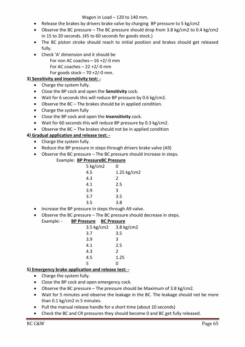
RC C&W Page 65
Wagon in Load – 120 to 140 mm.
Release the brakes by drivers brake valve by charging BP pressure to 5 kg/cm2
Observe the BC pressure – The BC pressure should drop from 3.8 kg/cm2 to 0.4 kg/cm2 in 15 to 20 seconds. (45 to 60 seconds for goods stock.)
The BC piston stroke should reach to initial position and brakes should get released fully.
Check ‘A’ dimension and it should be For non AC coaches—16 +2/-0 mm For AC coaches – 22 +2/-0 mm For goods stock – 70 +2/-0 mm.
3) Sensitivity and insensitivity test: -
Charge the system fully.
Close the BP cock and open the Sensitivity cock.
Wait for 6 seconds this will reduce BP pressure by 0.6 kg/cm2.
Observe the BC – The brakes should be in applied condition.
Charge the system fully
Close the BP cock and open the Insensitivity cock.
Wait for 60 seconds this will reduce BP pressure by 0.3 kg/cm2.
Observe the BC – The brakes should not be in applied condition 4) Gradual application and release test: -
Charge the system fully.
Reduce the BP pressure in steps through drivers brake valve (A9)
Observe the BC pressure – The BC pressure should increase in steps. Example: BP PressureBC Pressure 5 kg/cm2 0 4.5 1.25 kg/cm2 4.3 2 4.1 2.5 3.9 3 3.7 3.5 3.5 3.8
Increase the BP pressure in steps through A9 valve.
Observe the BC pressure – The BC pressure should decrease in steps. Example: - BP Pressure BC Pressure
3.5 kg/cm2 3.8 kg/cm2 3.7 3.5 3.9 3 4.1 2.5 4.3 2 4.5 1.25 5 0
5) Emergency brake application and release test: -
Charge the system fully.
Close the BP cock and open emergency cock.
Observe the BC pressure – The pressure should be Maximum of 3.8 kg/cm2.
Wait for 5 minutes and observe the leakage in the BC. The leakage should not be more than 0.1 kg/cm2 in 5 minutes.
Pull the manual release handle for a short time (about 10 seconds)
Check the BC and CR pressures they should become 0 and BC get fully released.

RC C&W Page 66
6) Passenger emergency valve test (PEV test): -
Charge the system fully.
Pull the alarm chain from inside the coach of extreme end.
BP pressure from PEV choke should exhaust by hissing sound and brake should apply.
Reset the alarm signal disk with the help of resetting key on PEASD.
Hissing sound should stop and brakes should get released. 7) Guards emergency valve test (GEV test): -
Charge the system fully.
Operate the guard’s valve handle.
Observe BP pressure should exhaust from Guards valve by hissing sound and brakes should apply.
Reset the handle and observe hissing sound should stop and brakes should get released. 84. Procedure of conducting rake test with RTR:
FormationtestingwithRTR: - (Rake test rig) 1) Leakage test of BP and FP: -
Charge the system fully – BP to 5 kg/cm2 FP to 6 kg/cm2
Stabilize the pressure for 3 minutes.
Close BP and FP cocks
Watch the drop in pressure for 3 minutes.
The leakage rate in FP and BP should not be more than 0.2 kg/cm2 in one minute. 2) Brake application and release test: -
Charge the system fully.
Apply brakes to full application position by drivers brake valve that is reducing BP pressure by 1.5 kg/cm2.
Observe the all BC’s of formation.
Max. BC pressure should be 3.8 kg/cm2.
Note piston strokes of all coaches and should be within limits and brake blocks are binding on wheels. The piston stroke should be –
o For (BMBC) bogie mounted cylinder coaches— 32 mm o For under frame mounted cylinder coaches – 85 +10 mm o For under frame mounted cylinder modified coaches – 65+ 05mm o For goods stock on Wagon in Empty- 85 + 10 mm
in Load – 130 + 10 mm.
Release the brakes by drivers brake valve charging the BP pressure to 5 kg/cm2
Observe the all BC’s pistons.
The BC pistons should reach to initial position and brakes should get released fully.
Check ‘A’ dimension and it should be For non AC coaches —16 +2/-0 mm For AC coaches – 22 +2/-0 mm For goods stock – 70 +2/-0 mm.
3) Passenger emergency valve test (PEV test): -
Charge the system fully.
Pull the alarm chain from inside the coach of extreme end.
BP pressure from PEAV choke should exhaust by hissing sound and brake should apply.
Reset the alarm signal disk with the help of resetting key on PEASD.
Hissing sound should stop and brakes should get released

RC C&W Page 67
4) Guards emergency valve test (GEV test): -
Charge the system fully.
Operate the guard emergency valve handle.
Observe BP pressure should exhaust from Guards valve by hissing sound and brakes should apply.
Reset the handle and observe hissing sound should stop and brakes should get released.
85. Air continuity test:
Air continuity test is conducted in order to ensure availability of compressed air form locomotive to the last vehicle for proper functioning of brakes.
It is conducted on the following situations: 1. At originating station on platform/yard while issuing fresh BPC in presence of TXR. 2. At enroute by driver and guard whenever there is
o Reversal/Change of locomotive o One or more vehicles attached/detached from/to the formation o After formation is made good at loading/unloading points o After any attention paid on brake system of rolling stock by closing any of the cut off
angle cocks for any reason Procedure of conducting Air Continuity Test: Then driver should bring the A9 valve to release position to increase the BP pressure to
5 Kg/Cm2 guard should ensure BP pressure of 4.8 Kg/Cm2 in the gauge Driver must charge BP and FP to 5 Kg/Cm2 and 6 Kg/Cm2 respectively. At the same time guard of the train must confirm the availability of BP and FP pressures to a minimum level of 4.8 Kg/Cm2 and 5.8 Kg/Cm2 respectively.
Then the driver should reduce the BP pressure to 3.5 Kg/Cm2 by moving the A9 valve to full service application position and guard should ensure the corresponding in BP pressure by 1.5 Kg/Cm2 in BP gauge of SLR and brakes should apply in this condition.
And brakes should release in this condition. Then the guard should keep open the GEV for one minute continuously to exhaust the
BP pressure and driver should ensure over shooting/deflection of Air Flow Indicator along with audio-visual sounds.
If brake is not the last vehicle then the BP cut off angle cock of the rearmost vehicle for one minute instead of GEV and, follow the above procedure.
After closing the GEV/Angle cock driver must ensure recharging of BP within normal time.
Then issue the fresh BPC/ Endorse the BPC. 86. Procedure to check Loco efficiency in case of air trouble: The following are the brakes provided in the Diesel/Electrical locos A9 automatic brake: with the application of A9 brake valve, formation and
conjunctional brakes will come. SA9 independent brake: With the application of SA9 brake valve, loco brakes only will
come. Hand brake: During securing the loco, by application of the hand brake, one brake
cylinder will comes in to action and applies three brake blocks. Dynamic brake: it is an electrical brake. By application of DB, traction motors will work
as generator and train speed will be controlled.

RC C&W Page 68
SN Type of LOCO Vacuum
on Dummy
Vaccum with 8mm dia. leak hole
plate
Angle cock
closed
7.5mm leak
adapter
1 Air brake system (dual brake) 580mm 530mm 5 Kg/cm2 4 Kg/cm2
2 Pure air brake system IRAB-I --- --- 5 Kg/cm2 4.8 Kg/cm2
Place the automatic loco pilot’s brake valve handle in ‘emergency’ position and start
the engine/s for building air pressure. Allow the main reservoir pressure to build upto 10+0.1 kg/cm2. Close the engine cock
for the brake pipe and couple 7.5mm dia leak hole special test coupling. Move the automatic brake valve handle from ‘emergency’ to release’ position to charge
brake pipe to 5 kg/cm2 Open the angle cock of the brake pipe where leak hole plate has been provided. Note
the pressure in the brake pipe gauge in the cap which should not fall below 4.8 kg/cm2
for pure air brake locos and 4 kg/cm2 pressure for dual brake locos in 20 to 25 seconds. Note: (a) If the locomotive fails to satisfy these test results, it should be considered defective.
(b) All locos leaving shed should have the test results entered in the log book/engine repair book with date and time of testing under the supervisor’s signature. Whenever there is a dispute, loc inspector and TXR should jointly check the locomotive.
87. PEASD & PEAV:
The passenger emergency alarm system consists of two main parts. 1. Passenger emergency alarm valve (PEAV) 2. Passenger emergency alarm signal device (PEASD)
The passenger emergency alarm valve consists of a spring loaded hollow piston fitted
with a check valve at the bottom. It has also got a control chamber at the bottom of the piston and a brake pipe chamber at the top of the piston. A 4mm diameter exhaust port is provided at the bottom of the valve to release the air from main brake pipe. The brake pipe chamber available at the top of the piston is connected with the PEASD through branch pipes.
The PEASD consists of a pilot valve which can be operated by pulling the chain by the passenger. It is also provided with two numbers of exhaust ports to facilitate the removal of air from the top of the piston (Brake pipe chamber) by pulling the chain.

RC C&W Page 69
WORKING During charging or normal running the control chamber as well as brake pipe chamber
is charged with 5 Kg/Cm2 through the restricted passage from the main brake pipe. The air which is available at the brake pipe chamber at the top of the piston is also made available at the top of the pilot valve of PEASD. During charging the spring loaded check valve closes the passage between main brake pipe and the exhaust of PEAV. (Ref. fig)
When the chain is pulled by the passenger, the pilot valve in PEASD is lifted first. The air
from brake pipe chamber of PEAV is then released through the exhaust ports of PEASD and in turn brings the pressure at the top of the piston to zero immediately. Due to the existence of control pressure at the bottom of the piston, the hollow piston gets lifted, which in turn connects the main brake pipe with the exhaust to deplete the air from main brake pipe to initiate brake application.
88. Necessity of compulsory release manually all the brakes of all the vehicles whenever there is a reversal or change of locomotive:
Whenever locomotive is detached from the formation to attach it in reverse direction B.P pressure will become “ZERO” in the formation and all the brakes are applied in the formation due to the presence of CR pressure .The CR pressure will be 5.0 KG/CM2 in front of the formation and 4.8 Kg/CM2 in rear of the formation which is equal to B.P before detaching. Now after attaching the same loco previous rear portion will become front portion with CR pressure of 4.8 Kg/Cm2 and the previous front portion will become rear portion with CR pressure of 5.0 Kg/Cm2. Now B.P is created up to 5.0Kg/Cm2 in the loco and charges the formation with 5.0 Kg/CM2 in the front portion and 4.8 Kg/CM2 in rear portion. But in the rear portion CR pressure is already with 5.0 Kg/Cm2 which cannot be reduced automatically to 4.8 Kg/Cm2. This difference of 0.2 Kg/Cm2 between B.P and C.R will not allow the brakes to release by activating the three pressure valve. To release the brakes the existing C.R has to be released from the D.V which is possible only with manual release.
When locomotive is changed in the same direction all the brakes are to released manually because all the locos cannot create air pressure exactly equal to each other. This will happen because of difference in gauge calibrations, gauge working and measuring errors. Sometimes one loco may create little more/less pressure when compared to other loco. When loco is changed and if that loco is creating lesser pressure than theprevioius loco due to the above reasons it cannot release the brakes automatically by creating B.P pressure which will be less than the previously existing CR pressure. 89. Poor brake power: Poor brake power: When brakes are applied to control/stop the train but the train will not under control / stop as required by the loco pilot of the train due to non application of brakes. This phenomenon is called poor brake power. Repercussions of poor brake power: Poor brake power can cause serious disasters.
Train may pass signal at danger (SPAD)
Train may stop out of platform causing inconvenience to passengers
Train can’t be controlled properly while passing through gradients. It may roll back in up gradient and move faster in down gradient. Poor brake power is very dangerous as it will lead to serious accidents involving heavy causalities.
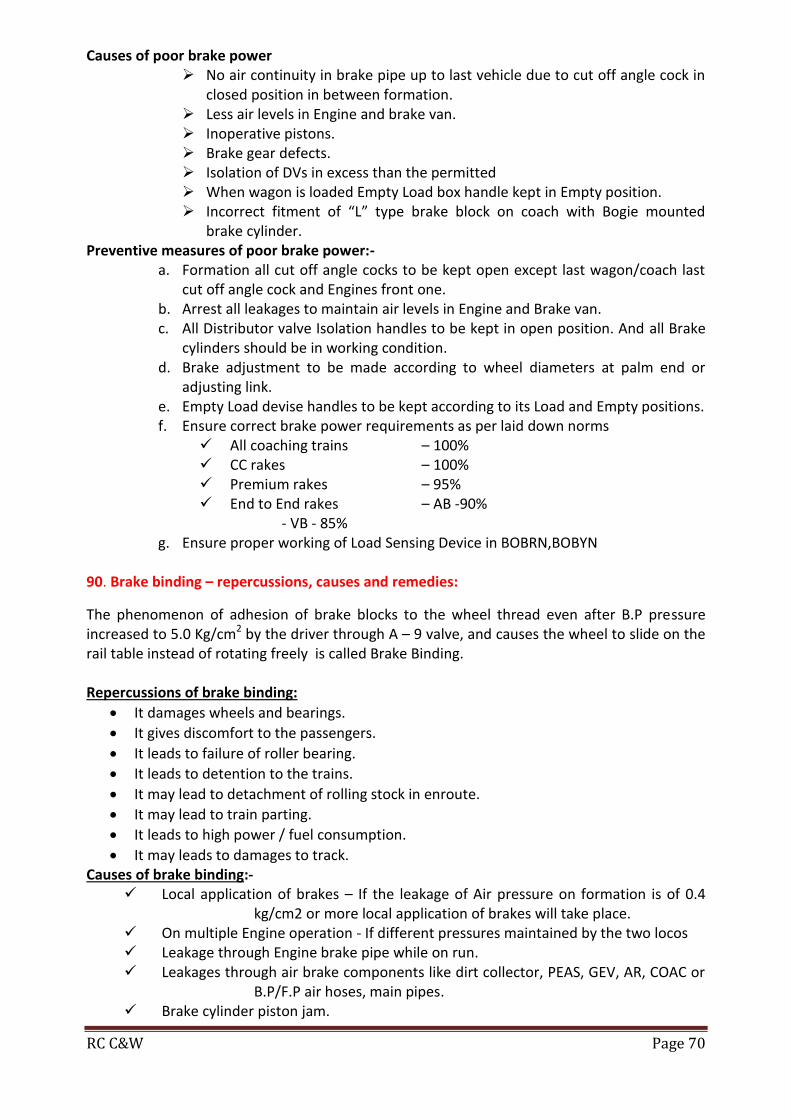
RC C&W Page 70
Causes of poor brake power No air continuity in brake pipe up to last vehicle due to cut off angle cock in
closed position in between formation. Less air levels in Engine and brake van. Inoperative pistons. Brake gear defects. Isolation of DVs in excess than the permitted When wagon is loaded Empty Load box handle kept in Empty position. Incorrect fitment of “L” type brake block on coach with Bogie mounted
brake cylinder. Preventive measures of poor brake power:-
a. Formation all cut off angle cocks to be kept open except last wagon/coach last cut off angle cock and Engines front one.
b. Arrest all leakages to maintain air levels in Engine and Brake van. c. All Distributor valve Isolation handles to be kept in open position. And all Brake
cylinders should be in working condition. d. Brake adjustment to be made according to wheel diameters at palm end or
adjusting link. e. Empty Load devise handles to be kept according to its Load and Empty positions. f. Ensure correct brake power requirements as per laid down norms
All coaching trains – 100% CC rakes – 100% Premium rakes – 95% End to End rakes – AB -90%
- VB - 85% g. Ensure proper working of Load Sensing Device in BOBRN,BOBYN
90. Brake binding – repercussions, causes and remedies:
The phenomenon of adhesion of brake blocks to the wheel thread even after B.P pressure increased to 5.0 Kg/cm2 by the driver through A – 9 valve, and causes the wheel to slide on the rail table instead of rotating freely is called Brake Binding. Repercussions of brake binding:
It damages wheels and bearings.
It gives discomfort to the passengers.
It leads to failure of roller bearing.
It leads to detention to the trains.
It may lead to detachment of rolling stock in enroute.
It may lead to train parting.
It leads to high power / fuel consumption.
It may leads to damages to track. Causes of brake binding:-
Local application of brakes – If the leakage of Air pressure on formation is of 0.4 kg/cm2 or more local application of brakes will take place.
On multiple Engine operation - If different pressures maintained by the two locos Leakage through Engine brake pipe while on run. Leakages through air brake components like dirt collector, PEAS, GEV, AR, COAC or
B.P/F.P air hoses, main pipes. Brake cylinder piston jam.

RC C&W Page 71
Hand brake in on position. S.A.B Defects. Brake beam bent. Empty Load devise handle kept in load position when wagon is Empty. When CR pressure is more than B.P – Occurs when loco is reversed or changed.
Remedies to prevent Brake Binding: Conduct rake test with RTR in pit line and Yard. Ensure no leakages are present. Check the working of brake cylinder and piston stroke for proper functioning. Check all isolating cocks are working properly. Ensure no accumulation of muck on D.V exhaust port. Ensure all cut off angle cocks are in open condition except the rear most. Release all the brake blocks manually by venting out CR pressure of all coaches /
wagons during checking. Overhaul the dirt collectors during “A” schedule. Clean and apply grease for PEASD during “B” schedule. Ensure correct fitment and correct type of brake blocks while replacing. Ensure proper working of Hand brake. Ensure proper working of DV with SCTR before releasing from Sick Line / ROH / IOH. Ensure Air continuity while issuing BPC and when ever coach / wagon is attached /
detached on to the formation. Ensure to release brakes manually when ever coach / wagon attached to the formation. Do release all the wagons / coaches brakes manually when ever locomotive is reversed
/ changed and banker engine is attached. 91. Procedure to attend brake binding at enroute on a coach:
Procedure for isolation of DV in case of brake binding enroute on a coach:
Identify the coach affected with brake binding.
Pull the manual release/quick release valve.
Observe whether brakes are released or not by shaking the brake blocks.
If released close all the isolating cocks and keep DV handle in horizontal position and allow the train to run.
If not released Close isolating cocks between BP& DV, FP & AR and keep DV handle in isolation
position. Drain out air from AR.
If brakes are released Close the isolating cock between DV and BCs and allow the train to start.
If not released continue the following operations till brakes are released. Drain out BC by opening the drain plug in case of UMBC Cut/remove the flexible pipe to drain the air from BC in case of BMBC
If brakes released allow the train to start.
If not released disconnect the brake rigging by removing brake gear pin.
Secure the brake rigging and allow the train to start.

RC C&W Page 72
92. Bye – passing of a coach affected with leakage in BP main pipe:
When there is leakage in FP main pipe the train can be run with single pipe system by closing the FP angle cock of the Locomotive. In case if BP main pipe is leaking the above process is not possible because train can’t work without BP. In that situation the particulars coach effected with leakage in BP main pipe has to be Bye-passed so that BP pressure shall not enter in to that coach. For that the following procedure is to be followed. Isolate the brake system of the effected coach as per procedure of attending brake
binding. Close the FP angle cock of loco on formation side. Close all the cut off angle cocks of the effected coach and those of the either side
coaches. Remove both the FP & BP air hoses by using suitable spanner from the angle cocks of
the effected coach. Refit the BP air hoses into the FP angle cocks of the effected coach. Now connect the BP palm ends of the either side coaches with BP palm ends of the
effected coach fitted in the FP angle cock. Open BP cut off angle cocks of the unaffected coaches and FP angle cocks of the
effected coach and allow the air to flow and observe for any leakages. Ensure the air continuity as per the procedure and endorse the BPC Allow the train to work with single pipe system.
93. How to calculate % brake power:
Total No.of cylinders on vehicle = N Total No.of not working cylinders(IOC, DY, TP)= n Total No. of working cylinders = N1 = N-n % brake power = No. of working cylinders X 100 Total No. of cylinders % B.P= N-n/N x 100= % Brake power 94. A brake cylinder of diameter 35.5 cm is charged with 3.8 kg/cm2. What is the force available at the piston: Brake force available on piston:- Diameter of cylinder = 35.5 Cm. (14”)
Area of piston = D2 / 4
= 35.52 / 4
= 990 Cm2
Brake Cylinder pressure = 3.8 Kg/cm2
Force available on the piston = BC pressure Area of piston
= 3.8 990
= 3762 Kg

RC C&W Page 73
95. Advantages of IR-DRDO Bio-Toilets:
Advantages
Green toilets aims at – Zero- Defecation on the ground
Discharge on track, besides creating environmental issues creates problem in working to workmen.
A multi directional strategy has been implemented for adoption of environment friendly toilets on IR passenger Coaches
Benefits of green toilets:
Environment friendly
Preventing damages to tracks due to corrosion
Improved aesthetic at Railway stations
Require less maintenance
Simple in design
Easier Retro fitment on existing coaches in service.
Can be in operation upto years together. 96. Double Decker coaches fitted with VESDA system: Positive features of Double Decker coaches:
Increased seating capacity per coach (120 seats)
Higher speed up to 160 kmph
Early warning smoke / fire detection with alarm system
Aesthetic interiors
Attached mini Pantry
Large side windows with foldable curtains Interior seating arrangement
S.No. Place of Seating Seat Nos. Total Seats
1 Middle Deck (Pantry Side) 01 – 06 06
2 Lower Deck 07 – 54 48
3 Middle Deck (Non-Pantry Side) 55 – 70 16
4 Upper Deck 70 – 120 50
Total 120 Seats

RC C&W Page 74
Comparison with Conventional Chair Cars (Moving Dimensions)
SN Parameter Double Decker
(LWCZDAC) Conventional
(WGCZAC)
1 Length 24000 mm 22297 mm
2 Width 3050 mm 3245 mm 3 Height 4366 mm 4025 mm
4 Seating capacity 120 seats 73 seats
5 Speed (C&M-I) 160 kmph 110 kmph
(other than C&M-1) 105 kmph 105 kmph
6 Cost (Rs in Crores) 2.86 1.54
Special features VESDA - Very Early Smoke / Fire Detection with Alarm System In Indian Railways it is the First introduction of Smoke / Fire detection with Alarm system in the Double Decker coaches Vide RDSO Spec No: RDSO/2008/CG-04 (Rev-01). Manufacturer: VESDA System is a very early warning smoke detecting system developed by M/s Xtralis, Australia. Maintenance:
Supply / Installation / Commissioning and Maintenance by firm M/s SIDWAL Refrigeration Industries Ltd, 108-A, New Delhi.

RC C&W Page 75
The vendor shall be liable for all schedule and unscheduled repairs of the systems installed by them for the satisfactory performance of the system for the entire warranty period – 24 months.
The vendor shall also give an offer for carrying out the annual maintenance of the system beyond the warranty period if consignee / Indian Railways so desires As per RDSO/Spec. No. RDSO/2008/CG-04 (Rev.-2)
Types of Levels in VESDA
SN Type of Levels Time
(in Sec) Density Type of Level Indicators
1 Alert Level 20 Sec 0.350 LED Light
2 Action Level 30 sec 0.600 Light Flashing
3 Fire Level 50 sec 1.60 Light Flashing & Hooter
Power Supply for VESDA and Monitoring system
In working times it will convert 110 v DC to 24 v DC in Non-working times 12 v + 12 v = 24 v from Battery.
All the coaches can be monitored from SLR by connecting Coach to Coach with the help of connectors.
Total Sensor points in coach Location Quantity
Lavatories 4 nos. (Heat melting points with 65°)
Doorways 2 nos.
Middle deck 4 nos.
Upper deck 3 nos.
Lower deck 3 nos.
Electrical panel 1 no.
Total 17 nos.

RC C&W Page 76
97. Attention of enroute trouble shooting in LHB coaches including Double Decker:
COUPLINGS
a) H-TYPE TIGHT LOCK CENTRE BUFFER COUPLER: - (Coaching Stock of ICF, LHB, DOUBLE DECKER & DURONTO COACHES)
‘H’ TYPE TIGHTLOCK CENTER BUFFER COUPLER COMPLETE - - -
3.
5. Mounting Plates
4.
1.
2.
3.
High tensile AAR 'H' type tight lock centre buffer couplers are now in use at some of the
latest coaching stock like ICF, LHB, Double Decker & DURONTO COACHES. Coupler is designed to take both draw and buffing forces. Located at the centre of the head stock with out side buffers.
Salient features are: - 1) Anti-climbing features to prevent excess damage to life and property during collision/accident
2) Coupler capacity is 200 tons where as conventional screw coupler is 75 ton. So that number of coaches can be increased.
3) Easy for operation and handling 4) Coupling and Uncoupling is automatic without entering the staff between the
coaches. The main Components of 'H' type tight lock centre buffer couplers are: - (1) 'H'- type tight lock coupler head (2) Manual uncoupling device. (3) Support device (4) Draft gear (5) Mounting plates. 1. Central pin support plate 2. Draft gear support plate HOW TO COUPLE LOCO & DESPATCH (FOR ‘H’ TYPE CBC COACHES)
1) Berthing of CBC rake on platform. 2) First five coaches should be kept in brake application position. Remaining all coaches should be kept in brake release position 3) Loco should be brought to the same line and to be stopped at 20 meters from the first
coach. 4) Coupler heights of the Loco and SLR should be in within limits (1105 to1030mm)

RC C&W Page 77
5) Remove the Restrictor of CBC coach. 6) Remove the tell-tale pin of CBC of Coach 7) Open the manual uncoupling devise lock with Multi purpose key available and lift the handle of Manual uncoupling devise for opening of knuckle of coach CBC. 8) Open the Knuckle of CBC of loco. 9) Examine there is any lubricant on internal parts of the Coupler body of the loco. In case any Lubricant/Grease available will be wiped out. 10) Align both the CBC’s in a line of gathering range. 11) Guide the loco pilot to proceed with 2 to 3 kmph for coupling. 12) After coupling check the coach CBC and loco CBC is locked properly by
Closed Condition Yellow Mark Visible
Tell Tale Slot is clear -
Rotary Lock Lifter rib is vertical
ENSURING PROPER LOCKING LATEST INSTRUCTIONS
Ensuring proper locking of Loco ’E’ Type CBC by Toggle below the coupler head by minimum 19mm 13) Ask loco pilot to take notch and test proper coupling of Knuckles. 14) Once coupling ensured provide tell-tale pin in slot with washer and spit pin. 15) The locking pin of Loco to be placed in position and to be tied up with GI wire. 16) Insert the Shims tightly and fix the Restrictor and tied with GI wire 17) Couple the Air hoses. 18) After ensuring proper air hose coupling, the brakes of the first 5 coaches should be
released. 19) The Loco pilot and Guard should ensure that the required amount of BP & FP air pressure is built up in Loco and rear SLR.

RC C&W Page 78
20) Ensure Continuity of air pressure before starting the train.
LHB AIR BRAKED TRAINS TROUBLE SHOOTINGS: -
1. BRAKE BINDING
Sequence of operationsfor attending Brake binding Of a LHB Trains including Double
Decker Trains: -
Check Indication lamps provided at coach body side panel. If Brake are binding Indication lamps
provided below the side body will show Red light.
NORMAL LHB COACH DOUBLE DECKER LHB COACH
Step-1: Pull the “Wire” provided below the coach.
BRAKE CONTROL PANEL AND INDICATOR UNIT
Brake indicatorBrake control panel
DV
Release Rod
Reservoir
Test fittingsIsolating cocks
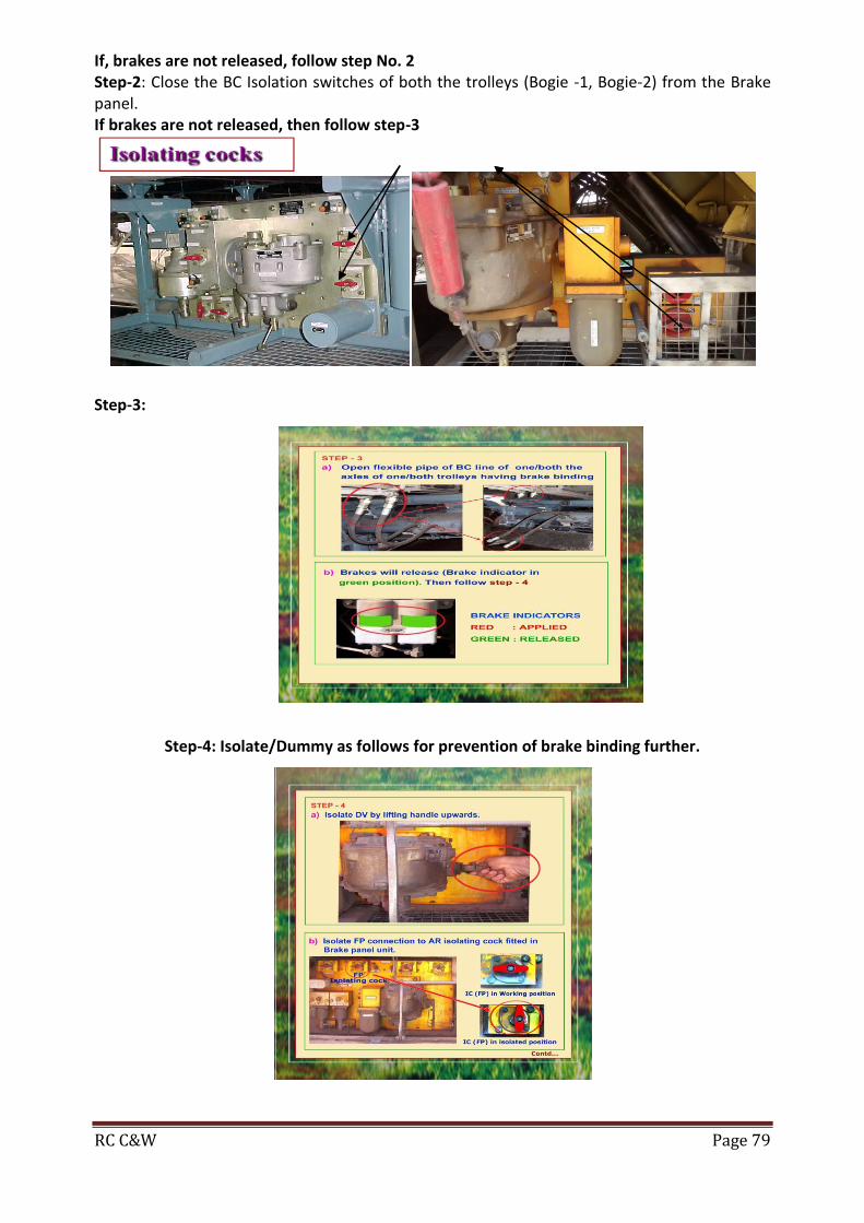
RC C&W Page 79
If, brakes are not released, follow step No. 2 Step-2: Close the BC Isolation switches of both the trolleys (Bogie -1, Bogie-2) from the Brake panel. If brakes are not released, then follow step-3
Step-3:
Step-4: Isolate/Dummy as follows for prevention of brake binding further.
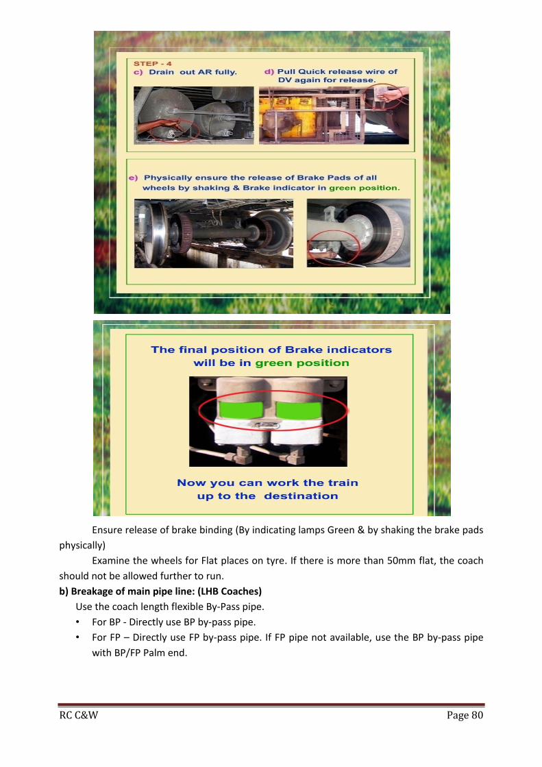
RC C&W Page 80
Ensure release of brake binding (By indicating lamps Green & by shaking the brake pads
physically)
Examine the wheels for Flat places on tyre. If there is more than 50mm flat, the coach
should not be allowed further to run.
b) Breakage of main pipe line: (LHB Coaches)
Use the coach length flexible By-Pass pipe.
• For BP - Directly use BP by-pass pipe.
• For FP – Directly use FP by-pass pipe. If FP pipe not available, use the BP by-pass pipe
with BP/FP Palm end.
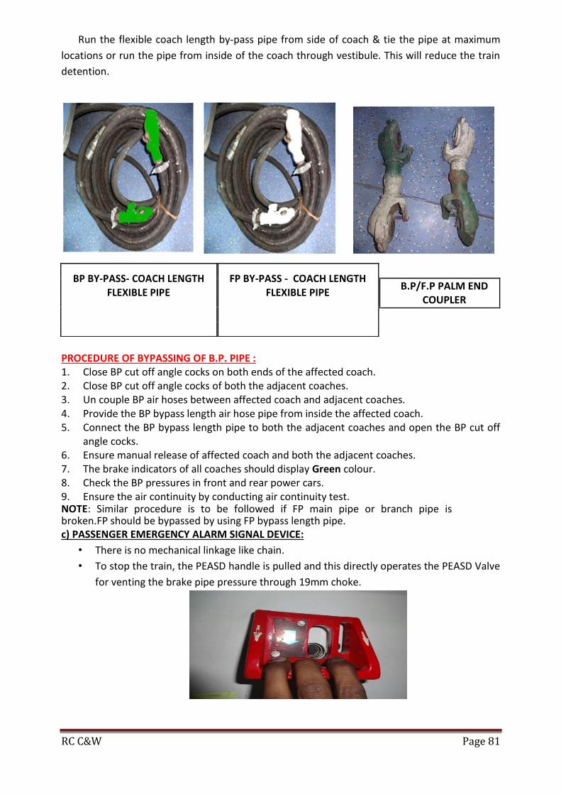
RC C&W Page 81
Run the flexible coach length by-pass pipe from side of coach & tie the pipe at maximum
locations or run the pipe from inside of the coach through vestibule. This will reduce the train
detention.
PROCEDURE OF BYPASSING OF B.P. PIPE : 1. Close BP cut off angle cocks on both ends of the affected coach. 2. Close BP cut off angle cocks of both the adjacent coaches. 3. Un couple BP air hoses between affected coach and adjacent coaches. 4. Provide the BP bypass length air hose pipe from inside the affected coach. 5. Connect the BP bypass length pipe to both the adjacent coaches and open the BP cut off
angle cocks. 6. Ensure manual release of affected coach and both the adjacent coaches. 7. The brake indicators of all coaches should display Green colour. 8. Check the BP pressures in front and rear power cars. 9. Ensure the air continuity by conducting air continuity test. NOTE: Similar procedure is to be followed if FP main pipe or branch pipe is broken.FP should be bypassed by using FP bypass length pipe. c) PASSENGER EMERGENCY ALARM SIGNAL DEVICE:
• There is no mechanical linkage like chain.
• To stop the train, the PEASD handle is pulled and this directly operates the PEASD Valve
for venting the brake pipe pressure through 19mm choke.
BP BY-PASS- COACH LENGTH FLEXIBLE PIPE
FP BY-PASS - COACH LENGTH
FLEXIBLE PIPE
B.P/F.P PALM END
COUPLER

RC C&W Page 82
During ACP, the red light provided outside the coach and a red light provided near
PEASD inside the cabin will glow.
For re-setting the PEASD, the resetting key is to be inserted on the projection available
near the PEASD and the key is to be rotated in the clock wise direction.
If the air leakage does not stop, then isolate the PEASD isolation cock provided under
the coach.
d. Cattle run over (CRO)
Following procedure to be adopted in case of CRO en route:
Thorough examination of rake should be done& attend the damages on the same site
as no further detention on the same account should take place.
The rake to be checked for air brake system, watering system, CDTS retention tanks, foot board & brake panel for damages/leakages & If the BP/FP metallic pipe is broken, by-pass the coach with the coach length by-pass flexible pipe.
e. Proper Coupling of CBC:
Ensure that the tell tale recess is clear
Ensure the lock lift assembly is dropped fully. The rivet of toggle (yellow colour) should
be clearly visible.
After ensuring proper coupling fix the restrictor.
The positive locking pin is inserted and secured properly with washer and split pin.
The manual uncoupling device is locked properly with multipurpose key.
The locking pin of Loco CBC should be inserted.

RC C&W Page 83
Insertion & securing of positive locking pin – toggle rivet marked yellow colour should be fully
visible.
Locking of cbc manual un coupling device with multi purpose key
f. LHB DOUBLE DECKER COACHES FITTED WITH AIR SPRING SUSPENSION IN SECONDARY
SUSPENSION & FIBA DEVICE
If Air spring burst or leaks, automatically brakes will apply and whistle sound comes
from the respective coach and the indicator provided at 4 corners of the coach also turn from
green to red color. Then close the respective coach Air spring Isolation cock in the FIBA panel,
then the indicator will show green & the train can be run with 60kmph up to destination.
* * * * *