Supervision Regulation on Safety Technology for …cbpvi.org/upload/88917/Supervision Regulation on...
171
1 Notice This English translation version is for reference only. In case of any discrepancies between English and Chinese version, the Chinese version shall govern. Supervision Regulation on Safety Technology for Stationary Pressure Vessels 1 General Requirement 1.1 Purpose In order to ensure the safe use of stationary pressure vessels, prevent and reduce accidents, protect the safety of human life and property, and promote the development of national economy, this Supervision Regulation on Safety Technology for Stationary Pressure Vessels (abbreviated Regulation, hereinafter) is established in accordance with “Law on Safety of Special Equipment of the People’s Republic of China” and “Regulations on Safety Supervision of Special Equipment”. 1.2 Stationary pressure vessels Stationary pressure vessels refer to pressure vessels installed and operated at fixed locations (hereinafter referred to as pressure vessels, see Note 1.1). Note 1-1: Pressure vessels to be moved and/or used within the certain scope of the facility or plant field for a particular purpose, as well as air tanks in transportable air compressor units are jurisdicted by this Regulation; heat recovery boilers in process devices designed and fabricated as process equipments based on pressure vessels are jurisdicted by this Regulation. 1.3 Applicable scope This Regulation is applicable to stationary pressure vessels defined in the catalogue of special equipment, and in conformity with all of the following conditions as a whole: (1) The working pressure is equal to or greater than 0.1 MPa (Note 1-2); (2) The volume is equal to or greater than 0.03 m 3 and the inside diameter (it refers to the maximum geometric dimension of the inside boundary at the cross-section for non-circular cross sections) is equal to or greater than 150 mm (Note
Transcript of Supervision Regulation on Safety Technology for …cbpvi.org/upload/88917/Supervision Regulation on...

1
Notice
This English translation version is for reference only. In case of any discrepancies
between English and Chinese version, the Chinese version shall govern.
Supervision Regulation on Safety Technology for Stationary
Pressure Vessels
1 General Requirement
1.1 Purpose
In order to ensure the safe use of stationary pressure vessels, prevent and reduce
accidents, protect the safety of human life and property, and promote the development
of national economy, this Supervision Regulation on Safety Technology for Stationary
Pressure Vessels (abbreviated Regulation, hereinafter) is established in accordance
with “Law on Safety of Special Equipment of the People’s Republic of China” and
“Regulations on Safety Supervision of Special Equipment”.
1.2 Stationary pressure vessels
Stationary pressure vessels refer to pressure vessels installed and operated at
fixed locations (hereinafter referred to as pressure vessels, see Note 1.1).
Note 1-1: Pressure vessels to be moved and/or used within the certain scope of the facility or
plant field for a particular purpose, as well as air tanks in transportable air compressor units are
jurisdicted by this Regulation; heat recovery boilers in process devices designed and fabricated as
process equipments based on pressure vessels are jurisdicted by this Regulation.
1.3 Applicable scope
This Regulation is applicable to stationary pressure vessels defined in the
catalogue of special equipment, and in conformity with all of the following conditions
as a whole:
(1) The working pressure is equal to or greater than 0.1 MPa (Note 1-2);
(2) The volume is equal to or greater than 0.03 m3 and the inside diameter (it
refers to the maximum geometric dimension of the inside boundary at the
cross-section for non-circular cross sections) is equal to or greater than 150 mm (Note

2
1-3);
(3) The medium is gas, liquefied gas or liquid which maximum working
temperature is equal to or greater than its standard boiling point (Note 1-4).
Note 1-2: Working Pressure, refers to the maximum pressure (guage pressure) possibly
occurred on the top of a vessel at normal working conditions.
Note 1-3: Volume, refers to the geometrical room of the pressure vessel, namely the volume
calculated based on the dimensions of the design drawings and after roundness (tolerance is not
considered). In general, the volume of the internals permanently amounted inside the pressure
vessel should be deducted.
Note 1-4: This Regulation is also applicable to the vessel when the maximum working
temperature of the containing liquid lower than its standard boiling point, meanwhile, the vapor
space volume is equal to or greater than 0.03m3.
1.4 Special provisions for applicable scope
Users shall be responsible for the safety management of their pressure vessels
subject to this Article according to the service management provisions in Chapter 7 of
this Regulation.
1.4.1 Pressure vessels which comply with the General Requirement, Material, Design,
and Fabrication only
Under the applicable scope of this Regulation, the following pressure vessels are
required to meet the provisions of only Chapter 1to Chapter 4:
(1) Non-independent pressure vessels of cryogenic installations, pressure vessels
of direct-fired absorption refrigeration equipments, aluminum plate-fin heat
exchangers, and pressure vessels in cold boxes of process equipments;
(2) Jacketed heat exchangers containing the medium group 2 (Note 1-5);
(3) Ultra-high pressure tubular reactor.
Note 1-5: Pressure vessel medium grouping see Annex A of this Regulation.
1.4.2 Pressure vessels conforming to General Requirement, Design and Fabrication
only
Under the applicable scope of this Regulation, the following pressure vessels are
required to meet the provisions of only Chapter 1, Chapter 3 and Chapter 4.

3
(1) Air tanks for transportable air compressor units;
(2) Air compressed hydraulic tanks used for hydraulic auto-pneumatic water
feeding devices (water feeding without tower), air and water feeding by air pressure
(foam) compressed tanks used for extinguishing devices;
(3) Pressure vessels used for ion exchange or filtration process in water treatment
equipments, water expansion tanks used for hot-water boilers;
(4) Pressure shell of accumulator.
1.5 Non-applicable scope
This Regulation is not applicable to pressure vessels as following:
(1) Transportable pressure vessels, gas cylinders and hyperbaric oxygen
chambers;
(2) Pressure vessels used for military equipment, nuclear facilities, aerospace
vehicles, locomotives, offshore installations and ships, as well as coal mines;
(3) Vessels with normal operating pressure less than 0.1MPa (including vessels
connecting to atmosphere with an instantaneous pressure no less than 0.1MPa during
feeding or discharging processes);
(4) Pressure containers that are as integral parts or components of rotating or
reciprocating mechanical devices, such as shell of pumps, shell of compressors, shell
of turbines, hydraulic cylinders, paper roller, etc;
(5) Plate heat exchangers, spiral plate heat exchangers, air-cooling heat
exchangers and cooling pipes.
(6) Steam heating coils of atmospheric pressure vessels, tubular heating furnace
of process equipments;
(7) Fully enclosed electric apparatus (capacitance pressure vessels) used for
power industry only;
(8) Tire vulcanizers and pressed rubber moulds used in rubber industry;
(9) Non-reinforced plastic pressure vessels.
1.6 Definition of pressure vessel scope
The jurisdiction scope of this Regulation covers pressure vessel bodies, safety
accessories and instruments.

4
1.6.1 Body of the pressure vessel
The main body of a pressure vessel is defined as following:
(1) The bevel surface of the first circumferential joint between a pressure vessel
and external pipes or devices connected by welding, the first threaded joint with
screwed connections, first flanged sealing surface with flanged connections and the
first sealing surface with special connectors or pipe connectors;
(2) Pressure covers and their fasteners of the openings of pressure vessels;
(3) Connection welds between non-pressure parts and pressure components.
Main pressure components in a pressure vessel body include forming shell
sections (including transition section reducers), petals of a spherical tank, shell plates
of a non-circular vessel, formed heads, flat heads, expansion joints, equipment flanges,
tubesheets and tubes of a heat exchanger; main bolts greater than M36 (including
M36) in specification, nozzle and pipe flanges with diameter no less than 250mm.
1.6.2 Safety accessories and instruments
Safety accessories of pressure vessels include safety valves directly connected
with pressure vessels, rupture disk devices, fusible plug, emergency shut-off devices
and safety interlock devices.
Instruments of pressure vessels include such measuring instruments directly
connected with pressure vessels as pressure gages, thermometric instruments, and
liquid level gages, etc.
1.7 Categories of Pressure Vessels
Depending on the hazard level, pressure vessels applicable to this Regulation are
classified into Category Ⅰ, Ⅱ, Ⅲ (Note 1-6), and the classifications of pressure
vessels see Annex A.
Note 1-6: Pressure vessels classified to CategoryⅠ,Ⅱ, Ⅲ in this Regulation are equal to the
first, second, third class pressure vessels in the catalogue of special equipment; Ultra-high
pressure vessels in this Regulation are classified to Category Ⅲ pressure vessels.
1.8 Inter-relationship with technical standards and management rules
(1) Regulation specifies the essential safety requirements of pressure vessels.
Involved technical standards and management rules of pressure vessels, as a minimum,

5
shall meet the requirements of this Regulation;
(2) The design, fabrication, installation, alteration and repair of pressure vessels
shall conform to the requirements of this Regulation and corresponding pressure
vessel product standards (hereinafter abbreviated as product standards).
1.9 The rule for handling inconformity to this Regulation
For pressure vessels constructed with new material, new technology, new process
and/or its special service conditions not meet the requirements of this Regulation, or
may cause significant impact on safety performance while not be stipulated in this
Regulation, involved enterprises/institutes shall submit the technical documentations
involving the foundation, data, results, as well as inspection and testing reports of the
design, research, and experiment to General Administration of Quality Supervision,
Inspection and Quarantine of P. R. China (abbreviated AQSIQ). Safety technology
advisory bodies or relevant professional organizations entrusted by AQSIQ shall carry
out technical evaluations and assessments. The pressure vessels cannot be put into
construction and service unless the results are approved by AQSIQ.
1.10 Harmonized standards and quoted standards
Harmonized standards of this Regulation refer to standards which comply with
the essential safety requirements of this Regulation. Main harmonized standards of
this Regulation are as follows:
(1) GB 150《Pressure Vessels》;
(2) GB 151《Heat Exchangers》;
(3) GB 12337《Steel Spherical Tanks》;
(4) NB/T 47011 《Zirconium Pressure Vessels》;
(5) NB/T 47041《Vertical Vessels Supported by Skirt》;
(6) NB/T 47042《Horizontal Vessels on Saddle Supports》;
(7) JB 4732《Steel Pressure Vessels- Design by Analysis》;
(8) JB/T 4734《Aluminum Welded Vessels》;
(9) JB/T 4745《Titanium Welded Vessels》;
(10) JB/T 4755《Copper Pressure Vessels》;
6
(11) JB/T 4756 《Nickel and Nickel Alloy Pressure Vessels》.
Quoted standards of this Regulation refer to basic standards appointed by this
Regulation, such as medium standards, material standards, measures standards, parts
standards.
Note 1-7: For harmonized standards or quoted standards in this Regulation with the year note,
both their amendment sheets (not including contents of corrections) and revisions do not apply to
this Regulation. Ones without the year note, their latest versions apply to this Regulation.
1.11 Supervisory administration
All parties involved in the design, fabrication, installation, alteration, repair,
service, inspection, and testing of pressure vessels shall implement the provisions of
this Regulation accordingly, subject to the supervisory administration of the
departments in charge of special equipment safety supervision and administration of
local people’s governments (hereinafter abbreviated as special equipment safety
supervisory administration departments), as well as follow the regulations of
information management for special equipment, and input required data into the
information systems in time.

7
Notice
This English translation version is for reference only. In case of any discrepancies
between English and Chinese version, the Chinese version shall govern.
2 Material
2.1 General requirements for materials
2.1.1 Basic requirements
(1) Mechanical properties, physical properties, process properties and the
compatibility with mediums shall be considered when selecting materials for
pressure vessels;
(2) The property, quality, specification and identification mark of materials
used for pressure vessels shall conform to the requirements of corresponding
National Standards or Industrial Standards;
(3) Manufacturers of materials for pressure vessels shall make clear and solid
hard stamp or other traceable identification marks at conspicuous locations of the
material;
(4) Manufacturers of materials for pressure vessels shall provide the material
quality certificate to manufacturers of pressure vessels. The content of material
quality certificate shall have complete and clear content, and printed with traceable
information identification marks, stamped with quality inspection by material
manufacturers;
(5) When the parties involved in fabrication, alteration and repair of pressure
vessels obtain materials not from materials manufacturers, an original material quality
certificate provided by the materials manufacturer or a copy of document with an
official seal of the material business units and a manager’s signature (stamp) is
required;
(6) The parties involved in fabrication, alteration and repair of pressure vessels
are responsible for the authenticity and consistency of the materials and its quality
certificates;
(7) Nonmetal pressure vessel manufacturers shall have reliable ways to
confirm the raw material or the material after molding can be reliably used in
corrosion conditions, and if necessary, a verification test shall be conducted.
8
2.1.2 The use of foreign designate materials
2.1.2.1 Materials produced by manufacturers outside P. R. China
(1) Foreign designate materials shall be the ones currently being allowed for
the pressure vessel based on relevant pressure vessel codes and standards in valid,
and also having sound experience in service under similar working conditions.
Its application scope shall conform to specifications of corresponding standards
and codes;
(2) Properties of foreign designate materials shall not be less than the basic
requirements of this Regulation (such as contents of S and P, sampling location and
direction of impact specimen and its impact energy, elongation);
(3) Material quality certificates shall conform to provisions of Article 2.1.1
of this Regulation;
(4) The parties involved in fabrication, alteration and repair of pressure
vessels shall review and verify physical materials and material quality certificates,
and re-examine the chemical composition and mechanical properties for materials
of main pressure components. The material can be put into use only after the
re-examination result conforms to the requirements of this Regulation and
respective material standards;
(5) While materials used for pressure components of welded pressure vessel
structure, parties involved in fabrication, alteration and repair of pressure vessels
shall conduct the welding procedure qualification based on the welding
performance of the material prior to the first application;
(6) When materials not listed in harmonized standards are to be adopted for
main pressure components, like the low alloy steel with specified tensile strength
low limit greater than 540MPa, or the low alloy steel used for design temperature
lower than -40℃, material manufacturers shall apply for a technical evaluation and
assessment and get approval according to Article 1.9 of this Regulation before the
material is allowed to be in use.
2.1.2.2 Steel plates (strips) produced by domestic manufacturers
Foreign designate steel plates (strips) produced by domestic manufacturers
shall conform to the requirements in Article 2.1.2.1 of this Regulation, and shall
formulate the enterprise standard.
9
2.1.2.3 Selection of foreign designate materials
If the Designer selects foreign designate materials, it shall explain in the
design document that the material conforms to the requirements in Article 2.1.2.1
of this Regulation.
2.1.3 Use of new materials
2.1.3.1 Materials not listed in harmonized standards of this Regulation
When materials not listed in harmonized standards are to be adopted for main
pressure components, the material pre-manufacturers shall carry out systematically
experiment and research before the trial production, and get approval according to
Article 1.9 of this Regulation.
2.1.3.2 Steel first produced by material manufacturers
When material manufacturers produce such materials for pressure vessels for the
first time, as the low alloy steel with specified tensile strength low limit greater than
540MPa, or the low alloy steel used for pressure vessels with the design temperature
lower than -40℃, they shall get approval according to Article 1.9 of this Regulation.
2.1.4 Materials usage and identification mark transfer
(1) The parties involved in fabrication, alteration and repair of pressure
vessels shall ensure the materials used for pressure vessels to be in conformity
with this Regulation, and verify the material quality certificates and material marks
by the material receiving inspection; for the material used for main pressure
components of which the authenticity of material quality certificate is uncertain or
the mechanical properties and chemical composition are doubtful, re-examination
on the material shall be conducted. The material cannot be put into fabrication
unless it is verified to conform to the requirements of this Regulation and
corresponding material standards;
(2) The purchased grade IV forging for the category III pressure vessel shall
be re-examined;
(3) The identification marks on materials for pressure components of pressure
vessels shall be transferred prior to cutting to ensure the traceability of materials.
2.1.5 Material substitute
When the parties involved in fabrication, alteration and repair of pressure
vessels intend to use substitute materials for main pressure components, the
written approval shall be provided from the original Designer in advance, and the

10
corresponding record shall be prescribed on the as-built drawing in detail.
2.2 Technical requirements of metal materials
2.2.1 Technical requirements of steel materials
2.2.1.1 Smelting methods
The steel used for pressure components of pressure vessels shall be killed
steel smelted by oxygen converter or electric furnace process. For low alloy steel
plates and austenite-ferrite stainless steel plates with the specified tensile strength
low limit greater than 540MPa, and the low temperature steel plates and low
temperature steel forgings generally used for design temperature lower than -20℃,
an additional out-of-furnace refining process is required.
2.2.1.2 Chemical composition (heat analysis)
2.2.1.2.1 Carbon steels and low alloy steels used for welded structure
The content of Carbon, Phosphor and Sulfur of carbon steels and low alloy
steels: C≤0.25%, P≤0.035%, S≤0.035%.
2.2.1.2.2 Carbon steels and low alloy steels specially used for pressure vessels
The content of Phosphor and Sulfur of carbon steels and low alloy steels
(steel plates, steel tubes and forgings) specially used for pressure vessels shall
meet the requirements as followings:
(1) For steel materials with the specified tensile strength low limit ≤540MPa,
P≤0.030%, S≤0.020%;
(2) For steel materials with the specified tensile strength low limit>540MPa,
P≤0.025%, S≤0.015%;
(3) For steel materials, of which design temperature lower than -20℃ and
specified tensile strength low limit ≤ 540MPa, P≤0.025%, S≤0.012%;
(4) For steel materials, of which design temperature lower than -20℃ and
specified tensile strength low limit>540MPa, P≤0.020%, S≤0.010%.
2.2.1.3 Mechanical properties
2.2.1.3.1 Impact energy
For steel plates with thickness no less than 6mm, tubes with the diameter and
thickness capable to make a 5mm sub-size impact specimen, and forgings with any
size, the impact energy (KV2) of V-notch specimen under the temperature of the
designed impact test shall meet the requirements in Table 2-1.

11
Table 2-1 Impact Energy of Carbon Steel and Low Alloy Steel
(Steel Plate, Steel Tube and Steel Forging) (Note 2-1)
Specified Tensile Strength Low Limit
Rm (MPa)
Mean Impact Energy of Three Standard
Specimens KV2 (J)
≤450 ≥20
>450~510 ≥24
>510~570 ≥31
>570~630 ≥34
>630~690 ≥38
(with lateral expansion LE≥0.53mm)
>690 ≥47
(with lateral expansion LE≥0.53mm)
Note 2-1:
(1) The sampling location and direction of a specimen shall conform to the specifications of
the related steel standard.
(2) Three standard specimens (10mm in width) shall be tested for each group of impact
test. It is allowed that one of individual specimens’ impact energy values is lower than those
listed in above table, but shall not be lower than 70% of the value.
(3) When steel material sizes are not sufficient for preparing standard specimens,
sub-size impact specimens with width of 7.5mm and 5mm shall be prepared separately, and
the impact energy for them shall be 75% and 50% of that for standard specimens respectively.
(4) For the steel material with its impact energy value required in the steel standards
higher than that in Table 2-1, the provisions of the relevant steel standards shall be followed
either.
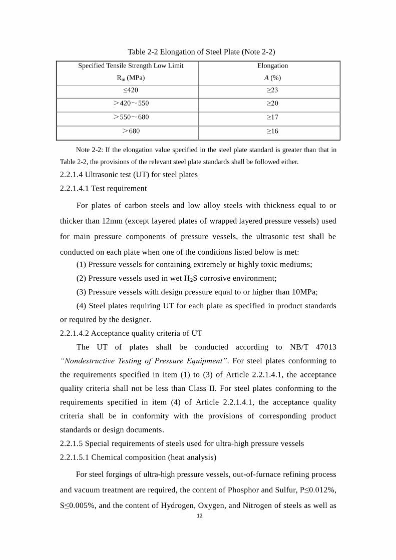
2.2.1.3.2 Elongation
(1) For steel plates, steel tubes and steel forgings for pressure components of
pressure vessels, their elongation (A) shall conform to the applicable requirements
of this Regulation and the corresponding steel standards.
(2) For plates of carbon steels, low alloy high-tensile steels and low alloy low
temperature steels used for welded structure, the elongation value shall meet the
requirements in Table 2-2;
(3) The elongation values of specimens whose dimensions are different from the
standard specimens shall be converted according to GB/T 17600.1 “Conversion of
steel elongation, part 1: carbon steels and low alloy steels” and GB/T 17600.2:
“Conversion of steel elongation, part 2: austenite steels”. The converted values shall
meet the requirements of this Article.
12
Table 2-2 Elongation of Steel Plate (Note 2-2)
Specified Tensile Strength Low Limit
Rm (MPa)
Elongation
A (%)
≤420 ≥23
>420~550 ≥20
>550~680 ≥17
>680 ≥16
Note 2-2: If the elongation value specified in the steel plate standard is greater than that in
Table 2-2, the provisions of the relevant steel plate standards shall be followed either.
2.2.1.4 Ultrasonic test (UT) for steel plates
2.2.1.4.1 Test requirement
For plates of carbon steels and low alloy steels with thickness equal to or
thicker than 12mm (except layered plates of wrapped layered pressure vessels) used
for main pressure components of pressure vessels, the ultrasonic test shall be
conducted on each plate when one of the conditions listed below is met:
(1) Pressure vessels for containing extremely or highly toxic mediums;
(2) Pressure vessels used in wet H2S corrosive environment;
(3) Pressure vessels with design pressure equal to or higher than 10MPa;
(4) Steel plates requiring UT for each plate as specified in product standards
or required by the designer.
2.2.1.4.2 Acceptance quality criteria of UT
The UT of plates shall be conducted according to NB/T 47013
“Nondestructive Testing of Pressure Equipment”. For steel plates conforming to
the requirements specified in item (1) to (3) of Article 2.2.1.4.1, the acceptance
quality criteria shall not be less than Class II. For steel plates conforming to the
requirements specified in item (4) of Article 2.2.1.4.1, the acceptance quality
criteria shall be in conformity with the provisions of corresponding product
standards or design documents.
2.2.1.5 Special requirements of steels used for ultra-high pressure vessels
2.2.1.5.1 Chemical composition (heat analysis)
For steel forgings of ultra-high pressure vessels, out-of-furnace refining process
and vacuum treatment are required, the content of Phosphor and Sulfur, P≤0.012%,
S≤0.005%, and the content of Hydrogen, Oxygen, and Nitrogen of steels as well as

13
toxic trace elements such as Arsenic, Stanum, Stibium, Plumbum, Bismuth shall be
strictly specified.
2.2.1.5.2 Mechanical properties
The manufacture of steel forgings used for pressure components of ultra-high
pressure vessels shall provide mechanical properties at room temperature,
including yield strength, tensile strength, elongation, shrinkage, Charpy (V-notch)
impact energy and lateral expansion, as well as the yield strength, tensile strength,
elongation, shrinkage of material at design temperature. In which KV2≥47J,
LE≥0.53mm, and when Rm≤880MPa,A≥16%;when Rm>880MPA, A≥14%.
When the smelting, forging or heat treatment process is changed, the fracture
toughness (KIC) and tough-brittle transition temperature (FATT50) of which
KIC≥130MPa·m½ shall also be provided.
2.2.1.6 Special requirements of steels used for non-welding shells of vessels as
cylinders (Note 2-3)
2.2.1.6.1 Steel material of the cylinder body
2.2.1.6.1.1 Smelting and heat treatment
(1) The steel material of cylinder bodies shall be smelted by electric furnace or
oxygen converter, and additional out-of-furnace refining process and vacuum
treatment are required;
(2) When the cylinder body is processed and formed, quenching
and tempering heat treatment shall be conducted and the metallographic structure
after heat treatment shall be tempered sorbite.
2.2.1.6.1.2 Chemical composition and mechanical properties
(1) For vessels as cylinders containing compressed gas such as hydrogen,
natural gas and methane, the chemical composition of steel material used for its
cylinder body, C≤0.35%, P≤0.015%, S≤0.008%; the mechanical property after heat
treatment is Rm≤880MPa, and the yield ratio (ReL refers to yield strength) is
ReL/Rm≤0.86, A≥20%; under impact test temperature required by design, KV2≥47J,
LE≥0.53mm, and the specimen shall be transverse;
(2) For vessels as cylinders containing other compressed gas except that

14
mentioned in Item (1) of this Article, the chemical composition of steel material
used for its cylinder body, P≤0.020%, S≤0.010%; the mechanical property after
heat treatment, Rm≤1060MPa, ReL/Rm≤0.90, A≥16%; under impact test temperature
required by design, KV2≥47J, LE≥0.53mm, and the specimen shall be transverse.
2.2.1.6.1.3 Ultrasonic test
100% UT of steel material used for cylinder bodies shall be conducted
according to NB/T 47013, and the acceptance quality criteria shall be ClassⅠ.
2.2.1.6.2 Steel material of the end plug
The steel material of end plug shall be matched with that of cylinder body and
use steel forgings which shall conform to the requirements of NB/T 47008
“Carbon and alloy steel forgings for pressure equipments”, NB/T 47009
“ Low-alloy steel forgings for low temperature pressure equipments”, NB/T 47010
“Stainless and heat-resisting steel forgings for pressure equipments”. The steel
forgings with nominal diameter equal to or greater than 50mm which contacted
with the medium shall not be less than Class Ⅲ; and the other forgings shall not
be less than ClassⅡ.
2.2.1.7 Special requirements of steels used for gas storage well
2.2.1.7.1 Steel tubes used for well tubes and couplings
The mechanical properties shall conform to the following requirements:
(1) When 689MPa<Rm≤750MPa, then ReL/Rm≤0.90, A≥18%; under impact
test temperature required by design, KV2≥41J (transverse specimen, the same
below), LE≥0.53mm;
(2) When 750MPa < Rm≤810MPa, then ReL/Rm≤0.91, A≥17%, KV2≥47J,
LE≥0.53mm;
(3) When 810MPa<Rm≤870MPa, then ReL/Rm≤0.93, A≥15%, KV2≥54J,
LE≥0.53mm.
2.2.1.7.2 Steel material used for wellhead and well bottom devices
For the gas storage well, the material of main pressure components of well head
and well bottom devices shall be Cr-Mo steel forgings with grade more than Class Ⅲ
15
(including Class Ⅲ), and shall meet the requirements of NB/T 47008.
2.2.1.8 Special requirements of steels used for simple pressure vessels
The carbon steel for simple pressure vessels shall conform to the following
requirements:
(1) Killed steel with supply state of hot rolling or normalizing;
(2) The chemical composition: C≤0.25%, S≤0.045%, P≤0.045%;
(3) The specified tensile strength low limit at room temperature is less than
510MPa.
Note 2-3: See Annex A for the definition of non-welding shells of vessels as cylinders, gas
storage well and simple pressure vessel.
2.2.2 Special requirements of clad steel plates
Clad steel plates used for pressure vessels shall be selected according to the
specifications of product standards, and shall meet the requirements as followings:
(1) The shear strength of the bonded interface of clad steel plates shall not be
less than 210MPa for stainless steel and steel, not be less than 210MPa for nickel
and steel, not be less than 140MPa for titanium and steel, not be less than 100MPa
for copper and steel, and not be less than 140MPa for zirconium and steel;
(2) The service condition of the base material for the clad steel plate shall
conform to the specifications of product standards;
(3) For the base material of the carbon steel and low alloy steel (including
steel plate and steel forging), the impact test shall be conducted according to base
material standards, and the impact energy value shall conform to base material
standards or provisions of the purchase contract.
2.2.3 Technical requirements of cast iron vessels
2.2.3.1 Application limitation for cast irons
Cast irons shall not be used for pressure components of pressure vessels
containing extremely, highly or moderately toxic mediums, and containing
explosive mediums with the design pressure equal to or higher than 0.15MPa. It
shall not be used for pressure components of tubular waste-heat boilers, and
splicing and welding repair are not allowable.
The following cast iron materials can be used for pressure vessels:
(1) Grey cast irons: HT200, HT250, HT300 and HT350;
16
(2) Nodular graphite cast irons: QT350-22R, QT350-22L, QT400-18R and
QT400-18L.
2.2.3.2 Limitation of design pressure and design temperature of cast iron vessels
(1) For grey cast irons, the design pressure shall not be higher than 0.8MPa
and the design temperature range is 10℃~200℃;
(2) For nodular graphite cast irons, the design pressure shall not be higher
than 1.6MPa, the design temperature range is 0~300°C for QT350-22R and
QT400-18R, -10℃ ~300℃ for QT400-18 L, and -20°C~300°C for QT350-22L.
2.2.4 Technical requirements of cast steel vessels
2.2.4.1 Application limitation for cast steels
Cast steels shall not be used for pressure components of pressure vessels
containing extremely, highly or moderately toxic mediums, and containing
explosive mediums with the design pressure equal to or higher than 0.4MPa, as
well as not be used in wet H2S corrosion environment.
2.2.4.2 Smelting and chemical composition of cast steels
The cast steel shall be killed steel smelted by electric furnace or oxygen
converter, its chemical composition (melting analysis), P≤0.035%, S≤0.035%; the
chemical composition of weldable cast steel, C≤0.25%, P≤0.025%, S≤0.025%;
out-of furnace refining or electroslag remelting shall be conducted for high alloy
austenite heat-resisting cast steel and its chemical composition, P≤0.035%,
S≤0.020%.
2.2.4.3 Properties of cast steels
The cast steel used for pressure components of pressure vessels shall be
selected according to the corresponding national standards or industrial standards,
and the material designation shall be indicated on the product quality certificate.
Its specified tensile strength low limit at room temperature is less than 540MPa,
A≥17%; KV2 under design temperature≥27J.
2.2.4.4 Limitation of design pressure and design temperature of cast steel vessels
(1) For carbon steel or low alloy carbon manganese steel vessels, the design
pressure shall not be higher than 2.5MPa and the design temperature range is
-20℃~400℃;
(2) For low alloy Cr-Mo steel vessels, the design pressure shall not be higher
than 4.0MPa and the design temperature range is 0℃~450℃;

17
(3) For high alloy austenite heat-resisting steel vessels, the design pressure
shall not be higher than 4.0MPa, and the design temperature upper limit shall take
that of forging steel with same designation for reference.
2.2.5 Technical requirements of nonferrous pressure vessels
2.2.5.1 General requirement
Nonferrous materials for pressure vessels (i.e. aluminum, titanium, copper,
nickel, zirconium and their alloys) shall meet the requirements as followings:
(1) Technical requirements of nonferrous materials shall be in accordance
with the provisions of product standards. The Additional requirements, if
necessarily, shall be prescribed on design drawings or indicated in corresponding
technical specifications;
(2) Manufacturers of pressure vessels shall establish the strict storage system,
and set specific areas to separate nonferrous materials from carbon and low alloy
steels.
2.2.5.2 Aluminum and aluminum alloy vessels
When used for pressure components of pressure vessels, aluminum and
aluminum alloys shall meet the requirements as followings:
(1) The design pressure shall not be higher than 16MPa;
(2) The design temperature range shall be -269~65℃ for aluminum alloys
with the magnesium content equal to or greater than 3% (e.g., 5083 and 5086), and
-269~200°C for other aluminum and aluminum alloys.
2.2.5.3 Copper and copper alloy vessels
When used for pressure components of pressure vessels, the design
temperature of the pure copper and brass shall be lower than 200℃.
2.2.5.4 Titanium and titanium alloy vessels
When used for pressure components of pressure vessels, titanium and
titanium alloys shall meet the requirements as followings:
(1) The design temperature shall not be higher than 315℃ for titanium and
titanium alloys, and not be higher than 350℃ for titanium-steel clad plates;
(2) Titanium and titanium alloys used for shells of pressure vessels shall be
used under the annealed condition.
2.2.5.5 Nickel and nickel alloys
Nickel and nickel alloys used for pressure components of pressure vessels

18
shall be used under the annealed or the solid solution condition.
2.2.5.6 Tantalum, zirconium, niobium and their alloys
When used for pressure components of pressure vessels, tantalum, zirconium,
niobium and their alloys shall be used under the annealed condition. The design
temperature shall not be higher than 250℃ for tantalum and its alloy, not be higher
than 375℃ for zirconium and its alloy, and not be higher than 220℃ for niobium
and its alloy.
2.2.6 Welding consumables
(1) For welding materials used for pressure parts of pressure vessels, the
tensile property of the filler metal shall conform to the specified low limit for the
base metal and the impact energy shall conform to the provision of Table 2-1 of
this Regulation; other properties of the filler metal shall not less than
corresponding requirements of the base meal when necessary;
(2) Welding consumables shall meet the requirements of standards for
corresponding welding consumables and products, and the supplier shall provide
the quality certificates of welding consumables with clearly and solidly tagged
labels;
(3) The parties involved in fabrication, alteration, and repair of pressure
vessels shall set up and strictly implement procedure of receiving, re-examination,
preservation, drying, delivery and reclamation for welding consumables.
2.3 Technical requirements of non-metal materials
2.3.1 Graphite pressure vessels
2.3.1.1 General requirements of graphite materials
(1) The graphite material used for pressure vessels shall be subject to
procedure qualification (including impregnation procedure qualification and
composite material forming procedure qualification), the procedure qualification
report and procedure qualification specification shall be approved by the technical
chief and confirmed by supervisory inspectors of the manufacturer; for the
qualified procedure and material, periodical verification shall be conducted (at
least once every six months);
(2) The graphite material and adhesive shall be consistent with the material
specified in procedure qualification specifications and be traceable;
(3) The source and grade of raw materials used for graphite materials and

19
adhesives shall be recorded on the procedure qualification report.
2.3.1.2 Requirements of graphite material properties
The mechanical properties of graphite material shall conform to the
requirements in Table 2-3.
Table 2-3 Mechanical Properties of Graphite Material
Items
Synthetic resin
impregnated
graphite tube
Synthetic resin
impregnated
graphite block
Synthetic resin
profiling graphite
tube
Lowest tensile strength
at room temperature 26MPa 14MPa 10MPa
Lowest tensile strength
at 205℃ 21MPa 11MPa 6MPa
Lowest bending
strength 39MPa _ 35MPa
Lowest compressive
strength 69MPa 45MPa 31MPa
Highest permeability
coefficient 2.9×10
-3mm
2/s 2.9×10
-3mm
2/s 2.9×10
-3mm
2/s
2.3.1.3 Requirements of adhesives
The adhesives shall be subject to property evaluation, and its mechanical
properties shall conform to the requirements in Table 2-4.
Table 2-4 Mechanical Properties of Adhesives
Items Adhesives (Note 2-4)
Lowest tensile strength at room temperature 10MPa
Lowest tensile strength at 205℃ 6MPa
Note: Adhesives refer to the mixture of graphite filler, synthetic resin and curing agent.
2.3.2 Fiber reinforced plastic pressure vessels
2.3.2.1 Fiber reinforces materials
The material used for fiber reinforces plastic pressure vessels shall be
impregnated well with resins and conform to design requirements. The
manufacturer shall examine the lowest strength of fiber which shall not less than
90% of fiber nominal property.

20
2.3.2.2 Resin matrix
The resin used for fiber reinforced plastic pressure vessels shall be consistent
with the material selected in design documents, and its heat deforming temperature
shall be re-examined before using and shall be 20℃ above higher than the design
temperature of pressure vessels.
2.3.2.3 Properties of adhesive materials
The property of material for adhesive shall not be lower than that for
component bonded.
2.3.2.4 Thermoplastic lining
The interlaminar shear strength of thermoplastic lining and fiber reinforced
plastic structure layer shall be equal to or more than 5MPa.

21
Notice
This English translation version is for reference only. In case of any discrepancies
between English and Chinese version, the Chinese version shall govern. 3 Design
3.1 General Requirements
3.1.1 License and responsibility of Designer
(1) The Designer and the legal representative shall be responsible for the
design quality of pressure vessels;
(2) The license of the Designer, as well as the categories of design licenses,
variety and scope for pressure vessels shall conform to the provisions of related
safety technical regulations;
(3) The design of pressure vessels shall conform to the essential safety
requirements of this Regulation. For pressure vessels designed by international
standards or codes outside P.R. China, the Designer shall provide Conformity
Declaration and Comparison Table to AQSIQ which declare the design has
satisfied the essential safety requirements specified in this Regulation;
(4) The Designer shall provide design documents specified in Article 3.1.4.1
of this Regulation to the design entrusting party.
3.1.2 Dedicated stamp for design
(1) A dedicated stamp for design (a copy of stamp is invalid) shall be sealed
by the Designer on the assembly drawing of the pressure vessel, and the design
drawings sealed the as-built stamp shall not be used for fabrication;
(2) The content of the dedicated stamp for design of pressure vessels shall at
least include the name of the Designer, serial no. of corresponding qualification
certificates, the legal representative and technical responsible personnel, etc.
3.1.3 Design specification
The design entrusting party shall provide the formal design specification of
the pressure vessel to the Designer in written. The design specification shall
include the following at minimum:
(1) Operating parameters (including working pressure, working temperature
range, liquid level height, load on nozzle, etc.);
(2) The location and natural conditions for the pressure vessel service
(including ambient temperature, seismic precautionary intensity, loads of wind and
22
snow, etc);
(3) Composition and properties of medium;
(4) Estimated service life;
(5) Geometric parameters, nozzle location and orientation;
(6) Other necessary specifications for the design.
3.1.4 Design documents
3.1.4.1 Content of design documents
(1) The design documents of pressure vessels include risk assessment report
(when necessary), strength calculation sheets or stress analysis reports, design
drawings, manufacturing technical specification. When necessary, the installation,
operation, and maintenance instructions shall also be included;
(2) When pressure vessels is equipped with safety valves or rupture disk
devices, the design documents shall also include the calculation sheets of safety
relieving capacity of pressure vessels, the discharge capacity of safety valves and
the relieving area of rupture disks. If simulating computation is adopted or these
calculations cannot be done, the pressure relief devices shall be selected by
consultation with the design entrusting party or the User.
3.1.4.2 Review and approval of design documents
For the risk assessment report, strength calculation sheets or stress analysis
reports, assembly drawings of design documents, at least three-step signing of
design, check, review and approval shall be conducted; for category III pressure
vessels, an approval signature (four-step singing) of the technical responsible
personnel or his / her authorized person of the pressure vessel Designer shall be
signed on the assembly drawing.
3.1.4.3 Retention period
The retention period of design documents shall not be less than the design
service life of pressure vessels.
3.1.4.4 Assembly drawing
3.1.4.4.1 Main content of the assembly drawing
The assembly drawing of pressure vessels shall include the following at
minimum:
(1) Name and category of pressure vessels, regulations and standards for the
design and manufacture;
(2) Working condition, including working pressure, working temperature,

23
properties of medium (toxicity and explosion damage degree, etc.);
(3) Design specifications, including design temperature, design loads
(including pressure and all sorts of loads to be considered), medium (composition),
corrosion allowance, welding joint efficiency, natural condition, etc; the maximum
filling ratio for tanks containing liquefied gas; limited content of corrosive
medium for storage pressure vessels with material having stress corrosion
tendency;
(4) Material designations and corresponding standards for main pressure
components;
(5) Main characteristic parameters (such as pressure vessel volume, heat
transfer area and passes number of heat exchanger);
(6) Design service life of pressure vessels (cycle number for vessels requiring
fatigue analysis);
(7) Special requirements for fabrication;
(8) Requirements for heat treatment;
(9) Requirements for nondestructive examination;
(10) Requirements for proof pressure test and leak test;
(11) Requirements for corrosion-proof (corrosion rate and stress corrosion
tendency of medium);
(12) Specifications of safety accessories and instruments as well we particular
purchase requirements (except considered in the process system);
(13) Location of the pressure vessel nameplate;
(14) Requirements for packing, transportation, field-assembly welding and
installation.
3.1.4.4.2 Particular requirements
The particular requirements for assembly drawing are needed for the
following situations:
(1) For pressure vessels with multiple chambers, the test pressure of each
pressure chamber shall be indicated individually. The allowable pressure
difference between two sides of the shared parts, and the test procedure and
requirements shall be indicated where special requirements existing;
(2) For pressure vessels filled with catalysts and fillings, the technical
requirements for periodic inspection in service shall be indicated;
(3) For pressure vessels incapable of internal inspections due to the structural

24
reason, the calculated thickness and the requirements for periodic inspection in
service shall be indicated;
(4) For pressure vessels incapable of proof pressure tests, the calculated
thickness and special requirements for fabrication and operation shall be indicated;
(5) For pressure vessels with the thermal-isolation lining, the requirements for
technical measures of preventing pressure components from over-heating shall be
indicated;
(6) For pressure vessels with the heat or cold insulation, the corresponding
measures shall be provided.
3.1.5 Design method
The design-by-rules or the design-by-analysis can be used for the design of
pressure vessels. When necessary, the experimental method, the empirical design
method or other design methods can also be used after got approval in accordance
with the provisions of Article 1.9 in this Regulation.
Based on the design specification in Article 3.1.3 of this Regulation, the
Designer of pressure vessels shall consider comprehensively all related factors,
failure modes and safety margin, to ensure the strength, rigidity, stability and
corrosion resistance of pressure vessels are sufficient. In the same time, the
Designer shall also consider the strength requirements of the welded joints
between the main body of pressure vessels and bearings, base rings, support lugs
as well as other supporting fittings to ensure the safety of pressure vessels in
design service life.
3.1.6 Risk evaluation
For category III pressure vessels or other pressure vessels required by the
User, the Designer shall provide a risk evaluation report which included main
failure modes, risk control, etc.
3.1.7 Requirements for energy-saving
In the design of pressure vessels, the principles of energy-saving and
consumption reduction shall be fully considered. The design shall meet the
requirements as the following:
(1) The economy of pressure vessels shall be fully considered to select the
material and the structural size appropriately;
(2) For heat exchangers, the design shall be optimized to increase efficiency
of heat exchanging and to meet the requirement of energy efficiency;

25
3.1.8 Load
The load required in Item (1), (2) of this Article shall be considered when
designing, and that in Item (3) to (10) shall also be considered when necessary.
(1) Internal pressure, external pressure or the maximum pressure difference;
(2) Static head pressure of liquid, which can be ignored when the static head
pressure of liquid is less than 5% of design pressure;
(3) Dead weight of the pressure vessel, and gravitational load of the pressure
vessel filled with mediums, catalysts and fillings etc. under normal working
conditions or proof pressure test condition;
(4) Gravitational load of accessory equipments and thermal-isolation
materials, linings, pipelines, staircases, platforms, etc.
(5) Wind load, seismic load, snow load, etc;
(6) Reacting force of bearings, base rings, support lugs as well as other
supporting fittings;
(7) Acting force caused by connecting pipelines and other parts;
(8) Acting force caused by temperature gradient or different thermal
expansion;
(9) Impact load, including the impact load caused by abrupt fluctuation of
pressure, reacting force caused by impacting of fluid, etc;
(10) Acting force generated in transportation or hoisting.
3.1.9 Pressure
3.1.9.1 Design pressure and calculated pressure
(1) Design pressure is defined as the maximum set pressure at the top of the
vessel and shall be applied as the conditions of design load with the corresponding
design temperature. The design pressure shall not be less than the working
pressure;
(2) Calculated pressure is defined as the pressure used to determine the
thickness of the parts with the coincident design temperature. It shall take
consideration of additional loads such as the static head pressure of liquid, etc.
3.1.9.2 Set pressure of pressure relief devices
(1) For pressure vessels equipped with pressure relief devices, the set pressure

26
of pressure relief devices shall not be higher than the design pressure of pressure
vessels;
(2) For pressure vessels, of which the maximum allowable working pressure
is indicated on design drawings, the set pressure shall not be higher than the
maximum allowable working pressure.
3.1.9.3 The design pressure for the pressure vessel containing liquefied gas at
ambient temperature
The design pressure for the pressure vessel containing liquefied gas at
ambient temperature shall be determined as the following based on the working
pressure at specified temperature:
(1) The working pressure at specified temperature for the pressure vessel
containing liquefied gas at ambient temperature shall be determined according to
Table 3-1;
Table 3-1 Working Pressure at Specified Temperature for Pressure Vessels
Containing Liquefied Gas at Ambient Temperature
Critical temperature
of liquefied gas
Working Pressure at Specified Temperature
without
Insulation
with Insulation
without
Temperature Actually
Measured by Test
with Maximum Operating
Temperature Actually Measured by
Test, and Ensuring it Less Than
Critical Temperature
≥50℃
Saturated Vapor
Pressure at 50℃
Saturated Vapor Pressure at Probable Maximum
Operating Temperature
<50℃ Gas Pressure at 50℃ under Maximum
Filling Ratio Specified by Design
Saturated Vapor Pressure at
Actually Measured Maximum
Operating Temperature by Test
(2) The working pressure at specified temperature for the pressure vessel
containing mixed liquefied petroleum gas at ambient temperature shall be
determined by the actual saturated vapor pressure of the mixed composition of
liquefied petroleum gas at the temperature not less than 50℃. The Designer shall
prescribe the limited composition and the corresponding pressure on the drawings.
When the actual composition data is unavailable or the composition analysis is not
made, the working pressure at specified temperature shall be not less than the
specified value as indicated in Table 3-2.
Table 3-2 Working Pressure at Specified Temperature for Pressure Vessels

27
Containing Mixed Liquefied Petroleum Gas at Ambient Temperature
Saturated Vapor Pressure of Mixed Liquefied
Petroleum Gas at 50℃ (MPa)
Working Pressure at Specified Temperature (MPa)
without Insulation with Insulation
≤Saturated Vapor Pressure of Isobutene at 50℃ Saturated Vapor Pressure
of Isobutene at 50℃
Saturated Vapor Pressure of
Isobutene at Probable
Maximum Operating
Temperature
>Saturated Vapor Pressure of Isobutene at 50℃
≤Saturated Vapor Pressure of Propane at 50℃
Saturated Vapor Pressure
of Propane at 50℃
Saturated Vapor Pressure of
Isobutene at Probable
Maximum Operating
Temperature
>Saturated Vapor Pressure of Propane at 50℃ Saturated Vapor Pressure
of Propylene at 50℃
Saturated Vapor Pressure of
Isobutene at Probable
Maximum Operating
Temperature
3.1.10 Temperature
(1) Design temperature is defined as the set metal temperature of the pressure
part under normal operating conditions of the pressure vessel, i.e. average of metal
temperature along the cross section of the pressure part. The design temperature
shall be as the conditions of design load with the coincident design pressure;
(2) When designing storage pressure vessels at ambient temperature, the
impact of atmospheric environment temperature on shell metal temperature of
pressure vessels under normal working conditions shall be fully taken into
consideration. The minimum design temperature shall not be greater than the
minimum value of average minimum temperature of the month over the years. It
may be calculated by the sum of the minimum temperature for each day of that
month divided by total days of that month.
3.1.11 Corrosion allowance
For pressure vessels with uniform corrosion, the corrosion allowance shall be
determined by the estimated service life and the material corrosive rate with the
involved medium. In the meantime, the impact of abrasion and erosion due to
medium flow shall also be taken into consideration for pressure components.
3.1.12 Minimum thickness
The minimum thickness of pressure vessels shall be determined by taking
consideration of the impact of manufacture, transportation, installation, etc.
3.1.13 Filling ratio
The design storage capacity of pressure vessels containing liquefied gas shall
be specified and the filling ratio shall not be greater than 0.95.
28
3.1.14 Inspection openings
(1) Inspection openings including manholes and hand holes shall be set on
pressure vessels when necessary. The location, amount and size of the inspection
openings shall meet the requirements of internal inspection;
(2) For pressure vessels required but incapable of setting inspection openings,
the Designer shall provide specific technical measures such as increasing the items
or length ratio of inspection in manufacture, and shall specify requirements about
key inspection items, methods of periodic inspection in service.
3.1.15 Non-detachable thermal isolation
For pressure vessels with the thermal isolation, if the isolation is unallowable
being detached in design, the requirements for the periodic inspection items and
methods in service shall be prescribed in the design documents. When necessary,
the particular requirements of full nondestructive examination on all welded joints
shall be prescribed on the drawings either.
3.1.16 Nondestructive examination
The method, length ratio, technical requirements, etc. of nondestructive
examination shall be specified by the Designer on design documents.
3.1.17 Proof pressure test
Proof pressure test shall be performed after the pressure vessel is fabricated.
Proof pressure tests include three types, i.e. hydrostatic test, pneumatic test and
pneumatic-hydrostatic combination test. The types, pressure, medium, temperature,
etc. of proof pressure test shall be specified by the Designer on design documents.
3.1.18 Leak test
After the proof pressure test completed and accepted, leak test shall be
conducted for the pressure vessel containing extremely or highly toxic medium, or
permitting no slight leakage as specified in designs. Depending on the difference of
test mediums, leak tests include gas leak test, ammonia leak test, halogen leak test and
helium leak test, etc. The types, pressure, technical requirements, etc. of leak test shall
be specified by the Designer on design documents.
For the pressure vessel requiring pneumatic test as specified on design drawings,
whether the leak test is required shall be prescribed on design drawings.
29
For the cast pressure vessel containing gaseous mediums, the request for gas leak
test shall be prescribed on design drawings.
For the pressure vessel equipped with pressure relief devices such as safety
valves, rupture disks, the Designer shall provide the maximum allowable working
pressure if gas leak test is required by designing.
3.2 Design requirements for metal pressure vessels
3.2.1 Safety factor and allowable stress
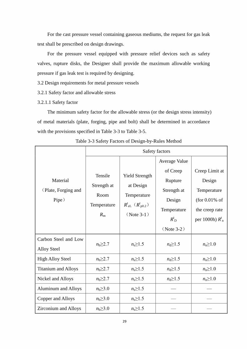
3.2.1.1 Safety factor
The minimum safety factor for the allowable stress (or the design stress intensity)
of metal materials (plate, forging, pipe and bolt) shall be determined in accordance
with the provisions specified in Table 3-3 to Table 3-5.
Table 3-3 Safety Factors of Design-by-Rules Method
Material
(Plate, Forging and
Pipe)
Safety factors
Tensile
Strength at
Room
Temperature
Rm
Yield Strength
at Design
Temperature
RteL(R
tp0.2)
(Note 3-1)
Average Value
of Creep
Rupture
Strength at
Design
Temperature
RtD
(Note 3-2)
Creep Limit at
Design
Temperature
(for 0.01% of
the creep rate
per 1000h) Rtn
Carbon Steel and Low
Alloy Steel nb≥2.7 ns≥1.5 nd≥1.5 nn≥1.0
High Alloy Steel nb≥2.7 ns≥1.5 nd≥1.5 nn≥1.0
Titanium and Alloys nb≥2.7 ns≥1.5 nd≥1.5 nn≥1.0
Nickel and Alloys nb≥2.7 ns≥1.5 nd≥1.5 nn≥1.0
Aluminum and Alloys nb≥3.0 ns≥1.5 — —
Copper and Alloys nb≥3.0 ns≥1.5 — —
Zirconium and Alloys nb≥3.0 ns≥1.5 — —

30
Table 3-4 Safety Factors of Design-by-Analysis Method
Material
(Plate, Forging
and Pipe)
Safety Factors
Tensile
Strength at
Room
Temperature
Rm
(Note 3-3)
Yield Strength
at Design
Temperature
RteL(R
tp0.2)
(Note 3-1)
Average
Value of Creep
Rupture
Strength at
Design
Temperature
RtD
(Note 3-2)
Creep Limit at
Design
Temperature
(for 0.01% of
the creep rate
per 1000h) Rtn
Carbon Steel and
Low Alloy Steel nb≥2.4 ns≥1.5 nd≥1.5 nn≥1.0
High Alloy Steel nb≥2.4 ns≥1.5 nd≥1.5 nn≥1.0
Table 3-5 Safety Factors of Stud (Bolt)
Material
Stud (Blot)
Diameter
(mm)
Heat Treatment
Conditions
Safety factors
Yield
Strength at
Design
Temperature
RteL(R
tp0.2)
Average Value
of Creep
Rupture
Strength at
Design
Temperature
RtD
(Note 3-2)
Carbon Steel ≤M22 Hot Rolled,
Normalized
2.7
1.5
M24~M48 2.5
Low Alloy Steel
and Martensitic
High Alloy Steel
≤M22 Quenched Plus
Tempered
3.5
M24~M48 3.0
≥M52 2.7

31
Austenite High
Alloy Steel
≤M22 Solid Solution
1.6
M24~M48 1.5
Note 3-1: For austenite stainless plate, if Rtp1.0 is specified in corresponding material
standards and allowed in product standards, it can be used for the calculation of the allowable
stress.
Note 3-2: This safety factor is the average value of creep rupture strength at design
temperature after 1.0×10⁵h.
Note 3-3: For design-by-analysis, if Rtm is specified in corresponding material standards, it can be
used for the calculation of the allowable stress.
The safety factor for the tensile strength of grey cast irons at room temperature
shall be not less than 10.0. The safety factor for the tensile strength of nodular
graphite cast irons at room temperature shall be not less than 8.0.
The safety factor for the tensile strength of cast steels at room temperature shall
be not less than 4.0.
When the safety factor selected by design is below the provisions specified in
this Regulation, it shall got approval in accordance with the provisions of Article 1.9
in this Regulation.
3.2.1.2 Allowable stress
The allowable stress of plate, forging and pipe shall be the minimum value of
tensile strength at room temperature Rm, yield strength at design temperature RteL
(Rtp0.2), average value of creep R
tD and mean creep limit at design temperature (with
creep rate 0.01% per 1000h) Rtn divided by the corresponding safety factor (Note 3-4).
Note 3-4: For pressure components made of austenite high alloy steel, when the design
temperature is lower than creep range and slight permanent deformation is permitted, the
allowable stress can be raised to 0.9 Rtp0.2 but no more than
(this provision is not applicable to
flanges or other situations when leak or failure occurs caused by slight permanent deformation);
for shells of austenitic stainless steel cryogenic vessels using cold stretching technique, the
allowable stress can be determined based on tensile strength at design temperature Rtm and yield
strength at design temperature RteL (R
tp0.2); for bodies of non-welding bottle type vessels, the

32
allowable stress can be determined based on the strength guarantee value after heat treatment
through which the product material properties have been improved.
The allowable stress of bolt shall be the minimum value of yield strength at
design temperature RteL (R
tp0.2), mean endurance strength at design temperature R
tD
divided by the corresponding safety factor.
3.2.2 Weld joint
3.2.2.1 Design of shell joint
For welded pressure vessels, full penetration weld joint shall be used for
Categories A and B butt joints (the classification of Categories A and B
butt-welded joints of pressure vessels is in accordance with the specification of GB
150).
3.2.2.2. Design of joint between nozzle and shell
For pressure vessels, the design for nozzle (flange)-to-shell joints and
jacketed pressure vessel joints, full penetration weld joint shall be used if any of
the following cases may occur:
(1) Pressure vessels containing inflammable and extremely or highly toxic
mediums;
(2) Pressure vessels requiring the pneumatic test or pneumatic-hydraulic
combination test;
(3) Category III pressure vessels;
(4) Low temperature pressure vessels;
(5) Pressure vessels designed by fatigue analysis;
(6) Directly fired pressure vessels;
(7) The Designer deemed necessary.
3.2.3 Joint efficiency
(1) For welded pressure vessels, the joint efficiency shall be determined
according to product standards based on the types of weld joints and
nondestructive examination length ratio;
(2) It is not allowed to exempt nondestructive examination of pressure vessels
by decreasing joint efficiency except for simple pressure vessels.
3.2.4 Test coupon (plate) and specimen
The Designer shall indicate the preparation requirements for welded test coupon
and corrosion resistance test coupon, and specify the type, quantity, interception and

33
preparation of specimens, as well as examination and test methods, acceptance criteria
and re-test request, etc.
3.2.4.1 Pressure vessels requiring preparation of the product welded test coupon
(1) Carbon steel and low alloy steel pressure vessels under low temperature
service;
(2) Low alloy steel pressure vessels with specified tensile strength low limit
greater than 540MPa;
(3) Pressure vessels containing extremely or highly toxic mediums;
(4) Pressure vessels using cold stretching technique (for continuous lot produced
pressure vessels with volume equal to or less than 5m3, it shall select 1 from 30
pressure vessels for preparation of the product welded test coupon at most under same
design and same material batch no.);
(5) The Designer deemed necessary or pressure vessels which the product
welded test coupon is required on corresponding product standards.
3.2.4.2 Preparation requirements for the corrosion resistance test coupon
(1) For pressure vessels or pressure components requiring the corrosion
resistance test, the corrosion resistance test coupon shall be prepared;
(2) For stainless steel and nickel alloy pressure vessels requiring the
inter-granular corrosion sensitivity test, their test coupons and specimens shall
conform to the specifications of GB/T 21433-2008 "Inter-granular Corrosion
Sensitivity Test of Stainless Steel Pressure Vessel" or corresponding product standards.
3.2.5 Nozzle flanges of pressure vessels
(1) For steel pressure vessels, the design for nozzle flange, gasket and fastener
shall refer to the specifications of HG/T 20592~HG/T 20635-2009 “Steel Nozzle
Flange, Gasket, Fastener”;
(2) For pressure vessels containing liquefied petroleum gas, extremely or highly
toxic mediums and moderately toxic mediums with strong penetrability, the design of
nozzle flange shall conform to the specifications of HG/T 20592 ~ HG/T 20635, and
shall use the combination of long welding neck flanges, spiral-wound gaskets with
reinforcing rings and high strength blots at special grade; for pressure vessels

34
incapable of using the nozzle flange seal combination, the Designer shall determine
the flange connection structure according to medium, pressure and temperature
properties.
3.2.6 Leakage telltale hole
For the reinforcement ring of the opening on the pressure vessel and the backing
having reinforcing function with continuous weld along periphery, at least one
leakage telltale hole shall be set. For each layer of the wrapped layered pressure
vessel, each shell ring of the integrally wrapped layered pressure vessel and both ends
of each single wall cylinder (except the inner cylinder) of shrink fit pressure vessels ,
at least one leakage telltale hole shall be set.
3.2.7 Particular requirements of corrosion-resistant
For pressure vessels or pressure parts that have particular requirements of
corrosion-resistant, for example those in corrosion medium condition with
inter-granular corrosion, stress corrosion, pitting corrosion, crevice corrosion, etc, the
corresponding corrosion-resistant measures, testing methods of corrosion resistance
and other technical requirements shall be prescribed on design documents.
3.2.8 Design of plastic lining
(1) The structure design of pressure vessels shall take consideration of the
deformation compatibility between metal base and plastic lining, and shall meet the
requirements of plastic lining process;
(2) A leakage telltale hole shall be set on the body of pressure vessel.
3.2.9 Water quality
For tubular waste-heat boilers, steam generator, etc., the water quality shall
meet the specifications of GB 1576-2008 “Water Quality for Industrial Boiler” or
GB/T 12145-2008 “Quality Criterion of Water and Steam for Generating Unit and
Steam Power Equipment”.
3.2.10 Nondestructive examination
3.2.10.1 Nondestructive examination methods
(1) The methods of nondestructive examinations for pressure vessels include
radiographic test, ultrasonic test, magnetic particle test, liquid penetration test and
eddy current test, etc., which shall be performed according to the provisions of NB/T

35
47013;
(2) When the nondestructive examination method is not included or exceed the
applicable scope of NB/T 47013, it shall apply the process evaluation and assessment
and get approval in accordance with the provisions of Article 1.9 in this Regulation.
3.2.10.2 Nondestructive examination of welded joints for pressure vessels
3.2.10.2.1 The selection of nondestructive examination methods
(1) For butt-welded joints of pressure vessels, the radiographic test (including
Film or digital imaging) or ultrasonic test shall be performed, ultrasonic test includes
the Time of Flight Diffraction Technique (TOFD), the recordable and un-recordable
Ultrasonic Pulse-echo Method; when using un-recordable Ultrasonic Pulse-echo
Method, radiographic test or TOFD shall be used as a spot examination additionally;
for butt-welded joints of large pressure vessels, when γ radiographic test for
panoramic exposure is performed, X radiographic test or TOFD shall be used as a 50%
spot examination additionally; if unacceptable defect occurs, a 100% X radiographic
test or TOFD reexamination shall be conducted.
(2) The radiographic test shall be preferably used for the welded joints of
nonferrous pressure vessels;
(3) The magnetic particle test or liquid penetration test shall be preferably used
for the surface cracks of welded joints;
(4) The magnetic particle test shall be preferably used for welded joints of
pressure vessels made of magnetic ferrite material.
3.2.10.2.2 Length ratio of nondestructive examination
3.2.10.2.2.1 Essential length ratio requirements
The length ratio of nondestructive examination for butt welded joints of pressure
vessels is generally divided into two kinds: full (100%) and spot (equal to or greater
than 20%) examinations. For carbon steel and low alloy steel pressure vessels under
low temperature service, the length ratio of the spot nondestructive examination shall
be equal to or greater than 50%.
3.2.10.2.2.2 The full examination by radiographic test or ultrasonic test
Categories A and B butt-welded joints of pressure vessels shall be performed the

36
full (100%) nondestructive examination with the method specified in the item (1) of
Article 3.2.10.2.1 in this Regulation for one of the following conditions:
(1) Pressure vessels containing extremely or highly toxic mediums;
(2) The category Ⅲ pressure vessels with design pressure equal to or greater
than 1.6 MPa;
(3) Pressure vessels fabricated by standards of design-by-analysis;
(4) Pressure vessels requiring pneumatic test or pneumatic-hydrostatic
combination test;
(5) Pressure vessels with welded joint efficiency of 1.0 or pressure vessels
incapable of internal inspection in service;
(6) Low-alloy steel pressure vessels with specified tensile strength low limit
greater than 540MPa;
(7) Welded joints which the Designer deemed it’s necessary to conduct the full
nondestructive examination.
3.2.10.2.2.3 Spot radiographic test or ultrasonic test
Each Categories A or B butt-welded joints of pressure vessels which are not
required full nondestructive examination shall be performed the spot nondestructive
examination with the method specified in the item (1) of Article 3.2.10.2.1 in this
Regulation.
3.2.10.2.2.4 Surface nondestructive examination
The magnetic particle test or liquid penetration test shall be carried out for the
welded joints for one of the following conditions:
(1) Welded joints of the pressure vessels containing extremely or highly toxic
mediums;
(2) Welded joints of the pressure vessels requiring pneumatic test or
pneumatic-hydrostatic combination test;
(3) Welded joints of the low alloy steel pressure vessels under low temperature
service with design temperature lower than -40℃;
(4) Welded joints of low-alloy steel, ferrite grades and austenite-ferrite grades
pressure vessels with specified tensile strength low limit greater than 540MPa; for

37
low-alloy steel pressure vessels with specified tensile strength low limit greater than
540MPa, the welded joints shall be performed magnetic particle test or liquid
penetration test after proof pressure test;
(5) Welded joints of austenitic stainless steel pressure vessels with thickness of
welded joints greater than 20mm;
(6) Welded joints of Cr-Mo low alloy steel pressure vessels;
(7) Surfacing, cladding welded joints of compound steel plate, welded joints of
the dissimilar steel, and the welded joints with the reheat cracking tendency and the
delayed cracking tendency; for the material having reheat cracking tendency, an
additional nondestructive examination shall be performed after heat treatment;
(8) All joints of convex heads which are formed after paneling;
(9) Welded joints which the Designer deemed it’s necessary to conduct the
surface nondestructive examination.
3.2.10.2.3 The technical requirements for nondestructive examination
3.2.10.2.3.1 Radiographic test
Radiographic test shall be performed in accordance with the specification of
NB/T 47013, the quality requirements and acceptable quality criterion are as follows:
(1) For butt-welded joints requiring full nondestructive examination, the
radiographic test technology level shall not be lower than Class AB, the acceptable
quality criterion shall not be lower than Class Ⅱ;
(2) For butt-welded joints requiring spot nondestructive examination, the
radiographic test technology level shall not be lower than Class AB, the acceptable
quality criterion shall not be lower than Class III.
3.2.10.2.3.2 Ultrasonic test
Ultrasonic test shall be performed in accordance with the specification of NB/T
47013, quality requirements and acceptable quality criterion are as follows:
(1) For butt-welded joints requiring full nondestructive examination, the
technical level of Ultrasonic Pulse-echo Method shall not be less than Class B, the
acceptable quality criterion shall be Class Ⅰ;
(2) For butt-welded joints requiring spot nondestructive examination, the
38
technical level of Ultrasonic Pulse-echo Method shall not be less than Class B, the
acceptable quality criterion shall not be less than Class Ⅱ;
(3) For fillet joints and T-shaped joints, the technical level of Ultrasonic
Pulse-echo Method shall not be less than Class B, the acceptable quality criterion
shall be Class Ⅰ;
(4) For welded joints tested by the Time of Flight Diffraction Technique (TOFD)
method, the acceptable quality criterion shall not be less than Class Ⅱ.
3.2.10.2.3.3 Combination examination
When combination of radiographic test and ultrasonic test used, the quality
requirements and acceptable quality criterion shall conform to the specification of
standards for radiographic test and ultrasonic test respectively, and both acceptable
quality criteria shall be met.
3.2.10.2.3.4 Surface nondestructive examination
The magnetic particle test or liquid penetration test of all pressure vessel welded
joints shall be performed in accordance with the specification of NB/T 47013, and the
acceptable quality criterion is as follows:
(1) For steel pressure vessels tested by magnetic particle or liquid penetration,
the acceptable quality criterion shall be Class I;
(2) For non-ferrous pressure vessels tested by liquid penetration, the acceptable
quality criterion shall be Class I.
3.2.10.2.4 Nondestructive examination requirements for nozzle welded joints.
(1) For butt welded joints of pressure vessel nozzles with nominal diameter equal
to or greater than 250mm, the nondestructive examination methods, length ratio and
the acceptable quality criterion shall be the same as that for welded joints of the main
body;
(2) For butt welded joints of pressure vessel nozzles with nominal diameter less
than 250mm, the nondestructive examination methods, length ratio and the acceptable
quality criterion shall be specified by the Designer or product standards.
3.2.10.3 Nondestructive examination requirements of raw materials and parts
Nondestructive examination methods, length ratio, and the acceptable quality

39
criteria of raw materials and parts shall be specified by the Designer according to this
Regulation and corresponding product standards.
3.2.11 Postweld heat treatment
(1) When the stress after welding affects safety service, the postweld heat
treatment (stress relief) shall be conducted for pressure vessels and pressure
components;
(2) The postweld heat treatment shall be conducted for carbon steel and low
alloy steel pressure vessels containing extremely mediums and pressure components.
When the stress relief methods other than the postweld heat treatment are used, it
shall apply the process evaluation and assessment and get approval in accordance with
the provisions of Article 1.9 in this Regulation.
Postweld heat treatment is generally not required for austenitic stainless steel
pressure vessels and non-ferrous pressure vessels. If heat treatment is necessary for
special requirements, it shall be specified on design drawings.
3.2.12 Proof pressure Test
3.2.12.1 Test pressure
The minimum test pressure shall be calculated by (3-1):
T t
p p
(3-1)
Where:
Tp — Test pressure,MPa;
— Pressure factor of proof pressure test,obtained from Table 3-6;
P — Design pressure of the pressure vessel or the maximum allowable working
pressure specified on the nameplate of the pressure vessel(for the pressure
vessel in service, generally taken as the allowable operation pressure or
supervisory operation pressure determined by the inspection),MPa;
— Allowable stress of material at test temperature ( or design stress
intensity),MPa;

40
t — Allowable stress of material at design temperature(or design stress
intensity),MPa
When the components of the pressure vessel (such as shell, head, nozzle,
equipment flange, man-hand hole flange and fastening etc.) are made of different
materials, the test pressure shall be calculated with the minimum value of
/ t
for the materials of each component; t shall not be less than the minimum
allowable stress of material controlled by the tensile strength and yield strength.
Table 3-6 Pressure Factor of Proof Pressure Test
Pressure Vessel Material
Pressure Factor
Hydrostatic Test
Pneumatic Test and
Pneumatic-Hydrostatic
Combination Test
Steel and Nonferrous
Metal 1.25 1.10
Cast Iron 2.00 —
3.2.12.2 Test temperature
During proof pressure test, the test temperature (the wall metal temperature of
the pressure vessel) shall be 30℃ higher than the nil ductility transition temperature
of the vessel metal, or be in accordance with the specifications of product standards. If
the nil ductility transition temperature of the material is raised due to the plate
thickness etc, the testing temperature shall be increased correspondingly.
3.2.12.3 Test medium
(1) Any liquid having no risk in test may be used as the hydrostatic test medium
at the temperature less than the boiling point of that liquid. When an inflammable
liquid is used as the hydrostatic test medium, the test temperature shall be less than
the flash point of that liquid;
(2) When the testing liquid cannot be filling into the pressure vessel due to the
reason of structure or support, or even a little amount of residual liquid in the pressure
vessel is not permitted due to operating requirements, a pneumatic test may be used;

41
the testing gases shall be dry and clean air, nitrogen or other inert gases;
(3) The pressure vessel which cannot be fully filled with liquid due to
load-bearing or other reasons may subject to pneumatic-hydrostatic combination test
with the routine of filling in part of liquid based on the load-bearing capacity firstly
and then filling in gas. The testing liquids and gases shall conform to the related
requirements of item (1) and (2) of this Article respectively.
3.2.13 Leak test
3.2.13.1 Gas leak test
The gases used in gas leak test shall conform to the item (2) of Article 3.2.12.3 in
this Regulation, and the test pressure is the design pressure of the pressure vessel.
3.2.13.2 Ammonia leak test
The ammonia leak test methods, such as ammonia-air method,
ammonia-nitrogen method, 100% ammonia method can be used. The ammonia
consistence, the test pressure, and the holding time for pressure are specified by the
Designer on design documents.
3.2.13.3 Halogen leak test
In halogen leak test, requirements of vacuum level inside the vessel, the type of
halogen gas, the test pressure, the holding time for pressure, and the test operation
procedure are specified by the Designer on design documents.
3.2.13.4 Helium leak test
In helium leak test, requirements of vacuum level inside the vessel, the
consistence of helium, the test pressure, the holding time for pressure, and the test
operation procedure are specified by the Designer on design documents.
3.2.14 Special requirements for the design of super-high pressure vessels
3.2.14.1 Design methods
(1) For super-high pressure vessels, burst pressure calculation method or elastic
plastic analysis shall be used for the design of static strength; when elastic plastic
analysis is used, the load amplification factor shall be equal to or greater than 2.0;
(2) Fatigue analysis shall be conducted for super-high pressure vessels.
3.2.14.2 Safety factor

42
3.2.14.2.1 Safety factor of burst pressure calculation method
For super-high pressure vessels, the safety factor shall be equal to or greater than
2.2 when the burst pressure is calculated according to the tensile test data of material,
and it shall be equal to or greater than 2.4 for super-high pressure crystal autoclave;
when the burst pressure is calculated according to the torsion test data of material, the
safety factor shall be equal to or greater than 2.2.
3.2.14.2.2 Safety factor of fatigue analysis
In fatigue analysis, the safety factor of alternative stress amplitudes and cycle
times shall be 2 and 15 respectively.
3.2.14.2.3 Safety factor of the stud (bolt)
The safety factor of yield strength at design temperature shall be equal to or
greater than 1.8.
3.2.14.3 Maximum wall temperature
A permanent-recordable temperature measuring device shall be set on the place
expected to show the maximum temperature, and the location and dimensions of
temperature measuring hole shall be specified; the maximum wall temperature of
super-high pressure vessels shall not be higher than the allowable service temperature
of steel.
3.2.14.4 Nondestructive examination
The methods of nondestructive examinations for super-high pressure vessels
include ultrasonic test, magnetic particle test, liquid penetration test and eddy current
test, etc. The Designer shall specify the methods, length ratio, perform timing and
technical requirements of nondestructive examination in design documents according
to the requirements of this Regulation and corresponding product standards.
3.2.14.5 Autofrettage treatment
Hydraulic boosting shall be used for autofrettage treatment, and appropriate
methods shall be used to control the circumferential strain of vessel wall which shall
not be greater than 2%.
3.2.14.6 Test pressure
For super-high pressure vessels, hydraulic test is generally used for proof pressure

43
test. The minimum test pressure (pT) shall be calculated by (3-2):
(3-2)
Where:
P ---- Design pressure of super-high pressure vessels (operation pressure for
super-high pressure vessels in service), MPa;
---- Yield strength at material test temperature, MPa;
---- Yield strength at material design temperature, MPa;
3.2.15 Special requirements for the design of simple pressure vessels
3.2.15.1 Assembly drawing
For simple pressure vessels, the assembly drawing shall not only meet the
requirements of Article 3.1.4.4 of this Regulation, and also include the followings:
(1) Welding methods and requirements;
(2) Burst test requirements when design-by-test is used.
3.2.15.2 Design methods
For simple pressure vessels, the wall thickness of main pressure components
shall be determined by testing or calculating.
3.2.15.2.1 Testing
For the simple pressure vessels designed by testing, the burst pressure at room
temperature shall not be less than 4 times of the design pressure, and the
circumferential permanent deformation rate shall not be greater than 1%.
3.2.15.2.2 Calculating
When the wall thickness of main pressure components is determined by
calculating, it shall meet the requirements as follows:
(1)The general membrane stress shall to equal to or less than 0.6Rp0.2, or be
0.3Rm;
(2) If there are manual welding longitudinal welded joints on the shell of
pressure vessels, the calculation thickness of shell shall be increased by 15%.
3.2.15.3 Minimum wall thickness
For austenitic stainless steel simple pressure vessels, the actual wall thickness of
44
shaped shell shall not be less than 1mm; for carbon steel simple pressure vessels, it
shall not be less than 2mm.
3.2.15.4 Spot-check of nondestructive examination
For the simple pressure vessels designed by calculating, the butt-welded joints
shall be subject to the spot check of radiographic test according to NB/T 47013, and
the technology level shall not be lower than Class AB, the acceptable quality criterion
shall not be lower than Class Ⅲ. The principle of spot-check are as follows:
(1) For butt-welded joints used automatic welding or machine welding, it shall
conduct radiographic test for the first product after the welding procedure is changed;
(2) In the process of manufacturing, at least one vessel shall be subject to
radiographic test for each batch products (note 3-5); it must take 1 for radiographic
test when the daily out is not enough to 1 batch;
(3) For butt-welded joints used manual welding, at least one vessel shall be
subject to radiographic test for the products welded by each welding operation
personnel (hereinafter referred to as welder) everyday.
(4) The longitudinal welds including cross welds shall be the preferable location
of radiographic test, the length for test of each product shall not be less than 200mm.
Note 3-5: The batch production principle for simple pressure vessels is in Article 4.2.9.2 of
this Regulation.
3.2.15.5 Proof pressure test
(1) The minimum test pressure shall be 1.5 times of the design pressure of simple
pressure vessels;
(2) In proof pressure test, the wall temperature of simple pressure vessels and test
medium shall not cause brittle fracture of vessels, and the temperature of test medium
is generally not lower than 5℃.
3.2.16 Special requirements for the design of quick opening pressure vessels
Pressure vessels with the quick opening closure are ones with quick seal
locking devices mutually nested with each other between the main body and the
head or end plate of the in-and-out path. Bolts connected vessels (such as swing
bolts) do not belong to quick opening pressure vessels. The impact of fatigue load

45
shall be taken into consideration for the design of pressure vessels with the quick
opening closure.
When designing quick opening pressure vessels, the Designer shall set safety
interlock devices, and specify the technical requirements such as its service
environment, calibration periodicity and calibration methods.
The safety interlock devices shall meet the following requirements:
(1) Operation for pressure cannot be started unless the quick opening closure
reaching the preset shut position;
(2) The quick opening closure cannot be opened until internal pressure of the
pressure vessel completely being released.
3.3 Design requirements of nonmetallic pressure vessels
3.3.1 Graphite pressure vessels
3.3.1.1 Design scope
The design scope of graphite pressure vessels is as follows:
(1) Maximum design external pressure, 2.4MPa;
(2) Maximum design internal pressure, 2.4MPa;
(3) Lowest design temperature, -70℃;
(4) Highest design temperature, 205℃.
3.3.1.2 Safety factor and allowable stress
The allowable stress value used in design shall be 80% of the tensile strength at
design temperature specified in graphite material procedure qualification report
(CMQ) or average of compression test divided by the safety factor 6.0 (when the
medium is extremely or highly toxic, the safety factor shall be 7.0).
3.3.1.3 Corrosion resistance
The graphite material selected shall keep the corrosion resistance in service
conditions.
3.3.1.4 Proof pressure test
The test pressure shall not be lower than 1.5 times of the design pressure; for
pressure vessels containing extremely or highly toxic mediums, the test pressure shall
not be lower than 1.75 times of the deign pressure.

46
The medium of proof pressure test generally is clean water.
3.3.1.5 Leak test
For pressure vessels containing extremely or highly toxic medium, the leak
test shall be conducted for all joints and junctions with test pressure not lower than
design pressure. The test method shall be specified by the Designer.
3.3.1.6 Bonding specimen
For pressure vessels containing extremely or highly toxic medium, the
Designer shall provide the preparation requirements of bonding specimens, and
specify the quantity and preparation of specimens, inspection and test methods,
acceptance criteria and re-test request etc.
3.3.2 Fiber reinforced plastic pressure vessels
3.3.2.1 General requirements
(1) Fiber reinforced plastic pressure vessels cannot use to contain extremely
or highly toxic medium and liquefied gas;
(2) Except the requirements of Article 3.1.5 of this Regulation, the layer
design of fiber reinforced materials shall be conducted along with strength
calculation and stiffness calculation simultaneously;
(3) The wall of fiber reinforced plastic pressure vessels is composed of inside
liner, structure layer and outside protection layer; only the pressure strength of
structure layer shall be consider for strength calculation of internal pressure; the
external pressure levels and dead load shall be calculated by the total thickness of
the pressure vessel;
(4) The anisotropy of compound materials and the property degradation caused
by material aging shall be considered;
(5) The design temperature of fiber reinforced plastic pressure vessels shall be
the working temperature of mediums and not lower than -54℃.
3.3.2.2 Design types
The design for fiber reinforced plastic pressure vessels are classified to the
following there types. The Designer shall determine the design type according to
design parameters, design methods, manufacturing procedures, etc. and indicate in
the design documents (assembly drawing):
(1)TypeⅠpressure vessel, when hand lay-up molding and spraying forming

47
process are used for manufacturing , the design pressure shall be equal to or less
than 1MPa; when filament winding process is used for manufacturing without pore
enveloping, the design pressure shall be equal to or less than 10MPa; when
filament winding process is used for manufacturing and pore enveloping is
performed, the design pressure shall be equal to or less than 20MPa; when the
working temperature is no greater than 65℃, the design temperature shall be 65℃;
when the working temperature is greater than 65℃, the design temperature shall
be no greater than 120℃, and the heat distortion temperature of resins used shall
be 20℃ above greater than the design temperature;
(2) TypeⅡpressure vessel, the filament winding process must be used for
cylinder shells, and the hand lay-up molding, spraying forming process or filament
winding process can be used for heads; when design-by-rules is adopted, the
product of working pressure and inside diameter shall be no greater than
2.4MPa·m, the maximum design pressure shall be no greater than 1.6MPa, the
maximum design inside diameter shall be no greater than 4.8m; when
design-by-analysis or the combination of design-by-rules and design-by-analysis is
adopted, the design pressure shall be no greater than 0.6MPa, the inside diameter
shall be no greater than 4m; the design temperature shall be no greater than 120℃,
and the heat distortion temperature of resins used shall be 20℃ above greater than
the design temperature;
(3) Type Ⅲ pressure vessel, the filament winding process and pore
enveloping must be used for manufacturing, and the design pressure shall be no
greater than 100MPa and no less than 20MPa; the design temperature shall be no
greater than 85℃, and the heat distortion temperature of resins used shall be 20℃
above greater than the design temperature.
3.3.2.3 Design methods and safety factor
(1) TypeⅠpressure vessel, prototype vessels shall be fabricated and 100
thousand times pressure fatigue test shall be conducted for the prototype vessels
with pressure range form normal pressure to design pressure. After the fatigue test,
pressure test shall be carried out with test pressure equal to or more than 6 times of
the design pressure, and no leakage or rupture happens to the vessel during the
test;

48
(2) TypeⅡpressure vessel,when design-by-analysis or the combination of
design-by-rules and design-by-analysis is adopted,and acoustic emission testing is
used for acceptance, the design safety factor of TypeⅡpressure vessels shall
consider the load conditions, forming process, service environment, temperature,
estimated service life, material discrete, etc; it shall improve the safety factor when
acoustic emission testing can’t be used; the design allowable strain shall be no
greater than 0.1%, and the external safety factor shall be no less than 5.0; the
specific safety factors of TypeⅡpressure vessels are specified in appropriate
product standards;
(3) Type Ⅲ pressure vessel, prototype vessels shall be fabricated and
whether the fatigue test is performed depends on design conditions. After the
fatigue test, pressure test shall be carried out. When carbon fiber reinforced plastic
is used for manufacturing, the test pressure shall be no less than 2.25 times of the
design pressure; when glass fiber reinforced plastic is used for manufacturing, the
test pressure shall be no less than 3.5 times of the design pressure. No leakage,
blisters, obvious deformation and rupture happens to the vessel during the test.
3.3.2.4 Lay-up design
The lay-up design for fiber reinforced plastic pressure vessels shall at least
include the followings:
(1) Types of fibers and fiber products;
(2) Resin system and composition;
(3) Sequence, direction and layers of lay-up;
(4) Forming process (including curing process);
(5) Resin content (weight ratio).
3.3.2.5 Bonding design
For bonding design, it shall ensure the allowable bearing capacity of bonding
joints is no less than the annulus load, axial load and radial load at the joints.
3.3.2.6 Proof pressure test
Hydrostatic test is generally used for proof pressure test, and the test medium
shall be clean water or other appropriate liquid; for pressure vessels not fit the
hydrostatic test, pneumatic test can be used.
The test internal pressure shall be no less than 1.1 times of the design internal
pressure, the test external pressure shall be no less than 1 times of the design

49
external pressure.
For TypeⅡpressure vessels, acoustic emission testing shall be carried out
for proof pressure test. When acoustic emission testing can’t be performed, the test
internal pressure shall be no less than 1.25 times of the design internal pressure,
the test external pressure shall be no less than 1.1 times of the design external
pressure and no greater than 0.1MPa.
3.3.3 Design for metal pressure components of nonmetallic pressure vessels
The design for metal pressure components of nonmetallic pressure vessels
shall conform to the corresponding provisions related to metal pressure vessels in
this Regualiton.

50
Notice
This English translation version is for reference only. In case of any discrepancies
between English and Chinese version, the Chinese version shall govern.
4 Fabrication
4.1 General requirement
4.1.1 Manufacturer
(1) The pressure vessel manufacturer (including field fabrication,
field-assembly welding, field bonding, see note 4-1) shall obtain the special
equipment manufacturing license, and fabricate within the approved scope,
establish and implement effectively the quality control system in accordance with
the requirements of relevant rules of laws, and safety technical regulations. The
manufacturer and main responsible person must be responsible for the quality of
pressure vessels;
(2) Manufacturers shall strictly enforce the relevant rules of laws, safety
technical regulations and technical standards, and fabricate pressure vessels in
accordance with the technical requirements of design documents.
Note4-1: The field fabrication, field-assembly welding, field bonding of stationary
pressure vessels, respectively refer to the fabrication on service field for large pressure vessels
(including spherical tanks) unable to transport, the assembly welding on service field for
section-by-section delivery pressure vessels, and the bonding on service field for nonmetallic
pressure vessels.
4.1.2 Type test (Prototype test)
Simple pressure vessels and accumulators shall pass through type (prototype)
tests taken by the approved type test institute of the AQSIQ, and the test items,
requirements and results shall satisfy the requirements of corresponding product
standards.
Prior to the first time of manufacturing bottle-type vessels and vacuum
insulation cryogen vessels, the manufacturer shall make a demo product and pass
through type (prototype) tests taken by the approved type test institute of the
AQSIQ, and the test items, requirements and results shall satisfy the requirements
of corresponding product standards.
4.1.3 Fabrication supervisory inspection
For pressure vessels requiring supervisory inspection (including the pressure
components and parts of pressure vessels in article 4.1.5.2 of this Regulations), the

51
manufacturers shall invite the special equipment inspection and testing institute to
conduct the supervisory inspection during their manufacturing process and obtain
the Supervisory Inspection Certificate of Special Equipment, then the pressure
vessels can be delivered.
4.1.4 Quality plan
(1) Prior to the manufacturing of pressure vessels, the manufacturer shall
make a sound quality plan (inspection plan), which shall include the vessels or
pressure components and parts, control point of fabrication procedure, inspection
items;
(2) During the manufacture process and after the completion of pressure
vessels, the manufacturer shall conduct corresponding inspection and testing for
vessels according to the timing specified in the quality plan, and the relevant
personnel shall make records or corresponding reports.
4.1.5 Product delivery documentation or as-built documentation
4.1.5.1 General requirement
When pressure vessels are delivered or completed, the manufacturers shall
provide Users with following technical documentations as a minimum, and offer
CD or other electronic mediums storing the electronic documents of pressure
vessel conformity certificates and product quality certification documents:
(1) As-built drawings, the as-built drawing shall be with the dedicated stamp
for design (duplication of stamp is invalid, exclude the batch produced pressure
vessels) and a finish seal (including the manufacturer name, the manufacturing
license number, a signature of review person and the sign of “As-built Drawing”).
If anything happened during fabrication, such as material substitution, change of
nondestructive examination method or change of final size etc., the manufacturer
shall clearly make indications on the as-built drawings in accordance with the
requirements in the written approval document from the Designer with the
signature of the person who makes changes and the date of changes at the
indication column;
(2) Pressure vessel conformity certificate (including Product Data Sheet, see
sample in Annex B) and product quality certification documents; product quality
certification documents include material list, material quality certificates of the
main pressure components, quality plan, checking report of appearance and
geometric dimensions, weld (bonding) map, nondestructive examination report,
52
heat treatment report and automatically recorded curves, proof pressure test report
and leak test report and a rubbing or a copy of the product’s nameplate etc; for
vacuum insulation pressure vessels, it also includes the inspection results of
sealing-off vacuum degree, vacuum interlayer leakage rate, static evaporation rate,
etc;
(3) Supervisory inspection certificate of special equipment (applicable to the
products where supervisory inspection are conducted);
(4) Pressure vessel design documents provided by the Designer.
Note 4-2: For simple pressure vessels, the manufacturer shall only provide the copy of
as-built drawing, product conformity certificate and Supervisory Inspection Certificate of
Special Equipment.
4.1.5.2 Product delivery documentations of pressure components and parts of
pressure vessels
For pressure components of pressure vessels (such as shell rings, heads,
forgings etc.) and pressure parts (such as heat exchanging tubes, man holes, etc.)
delivered individually, the manufacturers shall provide its quality certificate
documents to Purchasers.
4.1.5.3 Retention period
The retention period of product delivery documentation or as-built
documentation shall not be less than the design service life of pressure vessels.
4.1.6 Product nameplate
Manufacturers shall set the product nameplates in a conspicuous place on
pressure vessels. The nameplate shall be clear, solid, durable, and shall be written
in Chinese (in both Chinese and English when necessary) and SI unit. The contents
of the product nameplate shall at least include the following:
(1) Product name;
(2) Name of manufacturer;
(3) License number and level of manufacture licensing;
(4) Product standards;
(5) Materials of main body;
(6) Medium name;
(7) Design temperature;
(8) Design pressure, maximum allowable working pressure (when necessary);
(9) Pressure of proof pressure test;

53
(10) Product serial number or batch number;
(11) Equipment code (numbering method of special equipment code is in
Annex D);
(12) Date of manufacture;
(13) Pressure vessel category;
(14) Dead load volume (heat transfer area).
The format of product nameplate is in Annex C.
4.1.7 Design changes
When the manufacturer intends to change the original design, a written document
of agreement for the change shall be obtained from the original Designer. All the
changes shall be recorded in details.
4.1.8 Nondestructive examination
Manufacturers shall formulate and perform the process documents of
nondestructive examination according to the regulations of design documents. The
nondestructive examination personnel shall be qualified in accordance with the
relevant technical regulations to obtain a corresponding personnel certificate. And
then they can take charge of the nondestructive examination in correspondence with
the NDE method and Level in the certificate.
4.1.9 Proof pressure test
Manufacturers shall conduct the proof pressure test according to the regulations
of design documents after the pressure vessel is fabricated.
4.1.9.1 Preparations of proof pressure test
(1) All the fastenings at various connecting locations of the pressure vessel shall
be completely mounted and properly tightened prior to proof pressure test;
(2) The pressure gages used for test shall conform to the corresponding
provisions of Chapter 9 of this Regulation. At least two calibrated pressure gages with
the same measuring range shall be used and installed at the top of tested vessel for
easy observation;
(3) During proof pressure test, the appropriate measures for temporary pressure
parts welded on the pressure vessel shall be taken to ensure the strength and safety;
54
(4) The reliable safety protection measures shall be provided at the site of proof
pressure test, and be identified and accepted by the technical chief and the safety
department of the manufacturer.
4.1.9.2 General requirements for proof pressure test
(1) When the test pressure is higher than that specified in design documents, each
pressure components shall be subject to strength verification;
(2) During the holding period, any action of continuously raising pressure to keep
the pressure constantly is not allowed. During proof pressure test process, the
fastenings shall not be tightened and any external force shall not be applied on
pressure components;
(3) During the proof pressure test, any unrelated work is not allowed, and any
unrelated personnel shall not stay at the testing site;
(4) During the proof pressure test, the supervisory inspector shall be present on
site for supervisory inspection;
(5) There should be no fire source around the testing site, and some necessary fire
fighting equipments shall be provided;
(6) After the proof pressure test, if the repairing depth greater than 1/2 the
thickness of the vessel, one more proof pressure test shall be conducted.
4.1.9.3 Hydrostatic test
4.1.9.3.1 Procedures of hydrostatic test
(1) The test mediums shall conform to the requirements of product standards and
design drawings. When water used as the hydrostatic test medium, it shall be purged
out completely after the test is acceptably completed, and the water-based stain shall
be cleaned off when necessary;
(2) The tested pressure vessel shall be fully filled with testing liquid. Any gas in
the pressure vessel shall be purged out completely. And the outer surface of the
pressure vessel shall be kept dry;
(3) When the wall metal temperature of the pressure vessel is close to liquid
temperature, the pressure in testing may be raised up to the design pressure gradually.
After no leakage is identified, the pressure in testing shall be continuously raised up to
55
the specified test pressure, and be held for a sufficient time. Then the pressure is
relieved to the design pressure, and is held a sufficient time for inspection. During
inspection, the pressure shall be kept constant;
(4) The hydrostatic test procedure for heat exchangers shall conform to the
specifications of product standards.
4.1.9.3.2 Acceptance criterion of hydrostatic test
The hydrostatic test of the pressure vessel is acceptable when all the following
conditions are met:
(1) No leakage;
(2) No visible deformation;
(3) No unusual noise during testing.
4.1.9.4 Pneumatic test
4.1.9.4.1 Procedures of pneumatic test
(1) During testing, the manufacturer shall make an emergency plan and send
someone to supervise on testing site, withdraw the unrelated personnel;
(2) During testing, the pressure shall be gradually raised to 10% of the specified
test pressure, and be held for a sufficient time for the preliminary inspection on all
welds (bonding) and connecting locations. If no leakage occurs, the pressure in testing
may be continuously raised to 50% of the specified test pressure. If no any unusual
phenomenon occurs, the pressure in testing may be raised step by step with a gradient
of 10% of the specified test pressure up to the test pressure, and be held for a
sufficient time. Then, the pressure is relieved to the design pressure for inspection.
During inspection, the pressure shall be kept constant.
4.1.9.4.2 Acceptance criterion of pneumatic test
During the test, the pressure vessel with no unusual noise, no leakage during the
test of soap liquid or other liquid, and no visible deformation can be identified as
acceptable.
4.1.9.5 Pneumatic-hydrostatic combination test
Requirements for the pressure raising and pressure relieving, safety protection,
and the acceptance criteria during pneumatic-hydrostatic combination test shall

56
conform to the provisions of Article 4.1.9.4 in this Regulation.
4.1.10 Leak test
Manufacturers shall conduct the leak test according to the specifications of
design documents after the proof pressure test completed and accepted.
4.1.10.1 Gas tightness test
(1) During gas tightness test, in general the safety accessories shall be
completely mounted;
(2) After holding a sufficient time at the constant pressure, the pressure vessel
with no leakage shall be identified as acceptable.
4.1.10.2 Other types of leak test
The leak tests such as ammonia leak test, halogen leak test, helium leak test etc.
shall be conducted by the manufacturer according to the specifications of design
documents.
4.2 Requirements for fabrication of mental pressure vessels
4.2.1 Welding
4.2.1.1 Welding Procedure Qualification
The requirements of pressure vessel welding procedure qualifications are as
follows:
(1) Before pressure vessel products are welded, welded joints of pressure
components, welds to pressure components, tack welds that melt in permanent welds,
welding overlay and welding repair on the base metal of pressure components, as well
as welding repair of all welds mentioned above shall go through welding procedure
qualifications or be supported by qualified welding procedure specifications (WPS);
(2) The pressure vessel welding procedure qualification shall conform to the
requirements of NB/T 47014 "Welding procedure qualification for pressure
equipment";
(3) The supervisory inspector shall supervise the process of the welding
procedure qualification;
(4) Upon completion of the welding procedure qualification, the welding
procedure qualification record (PQR) and the welding procedure specification shall be

57
reviewed by the responsible welding engineer of the manufacturer , approved by the
technical chief of the manufacturer, signed and confirmed by the supervisory
inspector, and finally archived in technical files;
(5) The technical file of the welding procedure qualification shall be kept as long
as the expiry date of the welding procedure qualification, the specimens of the
welding procedure qualification shall be kept for at least 5 years.
4.2.1.2 Welder
(1) Welders engaged in welding operation of pressure vessels shall be qualified
in accordance with the provisions of related safety technical regulations, and hold the
personnel certificate of special equipment operator prior to welding within the scope
of applicable terms before the expire date;
(2) The welder shall perform welding in accordance with the welding procedure
specification or welding working instructions and take the field welding records. The
inspector of the manufacturer shall check the actual welding parameters;
(3) The welder’s symbol shall be stamped at the specified place adjacent to the
weld of the pressure component or record the welder’s identification in the weld map
(including welds layout drawing). The weld map shall be included in the product
quality certification documents;
(4) The manufacturer shall create the technical records for welders.
4.2.1.3 Splicing and assembly of pressure vessels
(1) Splicing is not allowed for shell plates of spherical tanks;
(2) The use of cross weld is not recommended on pressure vessels;
(3) Forced assembly is not allowed during the fabrication of pressure vessels.
4.2.1.4 Welding repair
The requirements of welding repair (including welding repair of base metal
defects) are as follows:
(1) The cause of defect shall be analyzed, and the appropriate procedure for
welding repair shall be presented;
(2) The welding procedure qualification of welding repair shall be carried out in
accordance with the Article 4.2.1.1 of this Regulation, or it shall be supported by

58
qualified welding procedure specifications. Welding repair shall be recorded in detail;
(3) It’s not recommended to carry out welding repair exceed twice at the same
position, or else, the welding repair shall be approved by the technical chief of the
Manufacturer before welding, and the number of repair, position and situations of
welding repair shall be recorded in the quality certification documents;
(4) For the pressure vessel requiring postweld heat treatment, generally, the
welding repair shall be performed prior to heat treatment. In case of the welding
repair after heat treatment, whether the stress relief heat treatment is necessary shall
depend on the depth of welding repair for defects;
(5) For pressure vessels or pressure components with particular requirements on
corrosion resistance, the corrosion resistance shall be kept not less than original
requirements after welding repair;
(6) The position of welding repair shall be re-examined and accepted in
accordance with the original requirements.
4.2.2 Test coupon (plate) and specimen
4.2.2.1 The preparation requirements for heat-treatment test coupon of the base metal
The heat-treatment test coupon of the base metal shall be prepared when heat
treatment is used for the material mechanical property (see Article 4.2.6.1 of this
Regulation) recovery or improvement in the manufacturing process.
When preparing above heat-treatment test coupon of a base metal, if the product
welded test coupon is required also, one combination test coupon is allowed.
4.2.2.2 The preparation of welded test coupon (plate)
(1) The product welded test coupon shall be at the extension portion of the
cylindrical longitudinal weld, and shall be welded simultaneously with the cylindrical
longitudinal weld (except for spherical pressure vessels and forged-welded pressure
vessels);
(2) The raw material of the test coupon shall be acceptable, and shall be of the
same material standard, same designation, same thickness, and same heat treatment
condition as those of the vessel;
(3) The test coupon shall be done by the welder who welds the pressure vessel
59
with the same condition and same welding procedures as the pressure vessel; for the
pressure vessel with the requirement of heat treatment, the test coupon shall generally
be heat-treated together with the pressure vessel. Otherwise, special measures shall be
taken to ensure that the test coupon is heat-treated in the same process as pressure
vessel;
(4) The pressure vessel test coupon used strain strengthening technique shall be
subject to the strain strengthening pre-stretching in accordance with corresponding
product standards.
4.2.2.3 Examination requirements of mechanical properties for both product welded
test coupon and heat treatment test coupon of the base metal
(1) The type, quantity, interception and preparation of specimens shall conform
to the specifications of design documents and product standards;
(2) The test methods, test temperatures, acceptance criteria and re-test request of
mechanical examination shall be in accordance with the specifications of design
documents and product standards.
4.2.3 Expanding
The flexible expanding methods or mechanical expanding methods may be used
for the expanded joint of tube-to-tubesheet of heat exchangers. Before expanding, an
expanding procedure specification shall be formulated, and the expanding operators
shall make the joint expanding in conformity with the expanding procedure
specification.
4.2.4 Appearance requirements
4.2.4.1 The appearance and geometric dimensions of cylindrical shells
The main examination items on appearance and geometry dimensions of shells
are as follows, whereas examination methods and acceptance criteria are in
accordance with the specifications of design documents and product standards.
(1) The main geometric dimensions, nozzle location and orientation;
(2)Abrupt rigid-or-valley and alignment offset of longitudinal and girth welds in
the single wall cylinder (including the inner shell of the wrapped layered pressure
vessel), cylinder shell and head, spherical shell;

60
(3) The loose area of the wrapped layered pressure vessel and the integrally
wrapped pressure vessel, the clearance between the shrink surface of the shrink-fit
pressure vessel;
(4) The inner dimension tolerance of the convex head, and the knuckle radius of
the torispherical head and toriconical head;
(5) Shape and dimensions of the circular shaped top plate and petals of the
spherical vessel;
(6) The transition size of the butt joint with unequal thicknesses.
4.2.4.2 Surface quality of welded joints
(1) The surface shall be free of various defects such as surface cracks,
incomplete penetrations, incomplete fusions, surface porosities, arc craters,
incomplete filled grooves, and visible slag inclusions etc;
(2) The weld shall have a smooth transition to the base metal;
(3) The shape of the fillet weld shall be in concave transition smoothly;
(4) For pressure vessels designed by fatigue analysis, the weld reinforcement for
longitudinal and girth welds shall be ground flush with the base metal;
(5)The undercut and other surface quality shall conform to the specifications of
design documents and product standards.
4.2.5 Nondestructive examination
4.2.5.1 The timing for performing nondestructive examination
(1) The visual inspection of shape, dimension and exterior of the pressure vessel
welded joints shall be performed to meet the criteria prior to nondestructive
examination;
(2) The nondestructive examination for welded heads shall be performed after
forming. If the nondestructive examination is performed prior to forming, then a
nondestructive re-examination shall be conducted from the knuckle to the straight
section of the formed head;
(3) For the material having delayed cracking tendency, the nondestructive
examination shall be performed at least 24 hours after welding.
4.2.5.2 The requirements for performing spot radiographic test or ultrasonic test

61
(1) The location of the spot nondestructive examination shall be specified by the
manufacturer based on the actual situation, but it shall include the intersecting
portions of the Categories A and B welds and the welds to be covered by other
components (note4-3);
Note 4-3: For glass-lined equipments, the nondestructive examination for assembly welds of
up and down attachment ring and the jacket as well as nozzle welded joints with nominal diameter
less than 250mm shall be in accordance with the specifications of national standards and industrial
standards of glass-lined equipments.
(2) When the unacceptable defect occurs at the welded joint by the spot
nondestructive examination, a supplementary spot examination of the length not less
than 250mm of the same welded joint shall be performed from both ends of the
examined parts. If the result still fails to meet the criteria, a 100% examination shall
be conducted on that welded joint;
(3) For pressure vessels with the spot nondestructive examination, the
Manufacturer shall still be responsible for the quality of welds which are not
performed any nondestructive examination.
4.2.5.3 Records and reports of nondestructive examination
Manufacturers or nondestructive examination institutes shall fill in
nondestructive examination records truthfully, issue the nondestructive examination
reports correctly, be responsible for the authenticity, accuracy and validity of the
nondestructive examination reports, and well preserve the examination records such
as radiographic films and ultrasonic test data (including the record before defects
repairing) and reports.
4.2.6 Heat treatment
4.2.6.1 The situations required heat treatment
(1) Postweld heat treatment required by design (see Article 3.2.1 in this
Regulation);
(2) When large deformation of material or large changes of structure caused by
cold forming in the manufacturing process affects the material microstructure and
mechanical property, or when the specified heat treatment condition of the base metal

62
in service are the same as that in delivery, if the heat treatment condition is altered in
the manufacturing process, the heat treatment for material property recovery shall be
conducted for pressure components;
(3) When heat treatment is required to achieve the design strength and toughness
index, the heat treatment for material property improvement shall be conducted for
pressure components.
4.2.6.2 The requirements for performing heat treatment
(1) Manufacturers of pressure vessels shall formulate the heat treatment
procedure and strictly implement. The specific technical requirements of heat
treatment shall be proposed for the field heat treatment;
(2) The postweld heat treatment shall be performed after the welding and
inspection are fully completed. All kinds of heat treatment shall be conducted before
the proof pressure test;
(3) The heat treatment equipment (furnace) is furnished with thermometers of
automatic curve records, and the time versus temperature curve shall be plotted.
4.2.7 Special requirements for pressure vessels of steel forgings, cast irons, stainless
steels and non-ferrous metals
4.2.7.1 Forged-welded pressure vessels
(1) For steel forgings of pressure vessels, the designation, the chemical
composition, mechanical properties, process performance and examination
requirements shall be in accordance with design drawings and the specifications of
product standards;
(2) When the verification ring of a circumferential weld is required by design
drawings, the material and dimensions of the ring, as well as the type, quantity,
interception, testing methods, and the acceptance criterion of the circumferential weld
test coupons shall be in accordance with design drawings;
(3) The cylindrical shell surface shall be machined, and the tolerances on
geometric dimensions (abrupt rigid-or-valley, alignment offset, roundness, butt weld
of unequal thicknesses, etc.) shall be in accordance with design drawings and the
specifications of product standards.

63
4.2.7.2 Cast pressure vessels
(1) The surface of cast iron pressure components must be free of cracks after
fabrication. The casting defects such as shrinkage cavities, sand inclusions, blowholes
and shrinkage porosities etc. shall not exceed the requirements specified on design
drawings. A liberal radius shall be provided at projecting edges and in reentrant
corners to avoid abrupt changes on the surface contour and the wall thickness at
junctures;
(2) A hydrostatic destructive test shall be conducted on the first trial product to
verify the design rationality. If the test result is unacceptable, the batch of the product
shall not be carried on. The test shall be properly planned with reliable safety
measures.
4.2.7.3 Stainless steel and non-ferrous metal pressure vessels
(1) When fabricating pressure vessels or pressure components with stainless
steels and non-ferrous metals, it shall have the specific workshop or specific
equipments and the field to avoid mixing with ferrous metals or other products. The
workshop or work field shall keep clean, dry and strictly control dust;
(2) The processing/forming equipment and welding facility shall meet the
requirements for the fabrication of stainless steels and nonferrous metals. Any
mechanical damage and splash on the surface shall be strictly controlled;
(3) For pressure vessels or pressure components with corrosion resistance and
corrosion prevention requirements, the surface treatment must be conducted based on
the requirements specified on design drawings, for instance, the austenitic stainless
steel surface can be treated by acid pickling and passivation.
4.2.7.4 Non-ferrous metal pressure vessels
4.2.7.4.1 Groove processing
In general, the groove surface shall be processed mechanically, and other cutting
methods that no damage to material properties and no effect on welding quality can
also be used. If thermal cutting methods are adopted for the groove preparation, the
oxidation layer and contamination layer shall be removed mechanically.
Requirements on the processed groove are as follows:

64
(1) For aluminum and titanium pressure vessels, cracks, laminations, inclusions
of impurities and other defects affecting welding quality are not permitted at the
groove surface;
(2) For copper and nickel pressure vessels, cracks, laminations, wrinkles, and
lacerations are not permitted at the groove surface.
4.2.7.4.2 Aluminum pressure vessels
All supports of horizontal pressure vessels made of aluminum shall be fully
contact with the shells.
4.2.7.4.3 Titanium pressure vessels
Titanium pressure vessels shall meet the following requirements:
(1) After welding, the surface color shall be inspected for all of the welded
joints under as-welded condition, and the acceptance criteria shall be in accordance
with product standards. The welded joints with unacceptable surface color shall be
treated according to the requirements of product standards;
(2) The titanium head should be processed by hot forming. During the hot
forming, necessary protection measures shall be taken to prevent the surface
oxidation and contamination according to the requirements of product standards.
After cold forming, the shape of the titanium head should be adjusted by heating.
4.2.7.4.4 Copper heads
For copper heads, if the stress corrosion cracking may occur under the specified
working environment, the annealing or stress relief annealing shall be performed in
accordance with the requirements of design drawings and product standards.
4.2.7.4.5 Pressure vessels of nickel and nickel alloy
The electrical furnace should be used for heating or heat treatment of nickel and
nickel alloy pressure vessels and pressure components, the fuel gas furnace or the fuel
oil furnace is also acceptable, but the coke or coal furnace is not allowed. When the
gas furnace or the fuel oil furnace is used, the sulfur content in gas or oil shall be
strictly controlled according to the requirements of product standards.
4.2.8 Special requirements for fabrication of super-high pressure vessels
4.2.2.8.1 Material examination

65
(1) After the property heat treatment for main pressure components forgings of
super-high pressure vessels, mechanical property at room temperature testing for the
forgings shall be conducted to test the tensile strength, yield strength, elongation,
Charpy (V-notch) impact energy and literal expansion. Meanwhile, the
metallographic analysis and hardness test shall be performed, which result shall
conform to the design technical conditions;
(2) For the outsourcing cylinder shell forgings of super-high pressure vessels, the
manufacturers shall conduct the re-test one by one based on material standards; the
re-test items include chemical composition, mechanical property, macrostructure,
grain size, nonmetallic inclusion and nondestructive examination; for other
outsourced forgings of pressure components, the outsourcer shall provide complete
forging material quality certificates and inspection reports.
4.2.8.2 Nondestructive examination
4.2.8.2.1 Nondestructive examination personnel
The nondestructive examination of super-high pressure vessels shall be
performed by the personnel obtained special equipment nondestructive examination
qualification certificate with level greater than or equal to Category Ⅱ, and
experienced in pressure vessel forging examination. The ultrasonic test report shall be
approved by the nondestructive examination personnel acquiring Category Ⅲ
qualification certificate.
4.2.8.2.2 The timing for performing nondestructive examination
(1) A 100% ultrasonic test shall be conducted for the cylinder shell of super-high
pressure before and after the quenching and tempering respectively. Ultrasonic test
with straight probe and tilting probe shall be conducted simultaneously after the
quenching and tempering. At least once 100% ultrasonic test shall be conducted for
other pressure components;
(2) A 100% magnetic particle test or liquid penetration test shall be conducted for
the internal and external surface of cylinder shell after mechanical processing (only
external surface examination can be conducted for the cylinder shell with inside
diameter less than 500mm). For the cylinder shell with outside diameter less than

66
250mm, only eddy current test can be conducted;
(3) For the cylinder shell used autofrettage technique, a 100% ultrasonic test
shall be conducted for the cylinder shell after autofrettage treatment;
(4) After proof pressure test, more than or equal to 20% ultrasonic test and 100%
surface examination shall be conducted for the cylinder shell (only external surface
examination can be conducted for the cylinder shell with inside diameter less than
500mm).
4.2.8.3 Autofrettage treatment
Manufacturers shall formulate and perform the autofrettage treatment procedure
according to the specifications of design documents.
4.2.9 Special requirements for the fabrication of simple pressure vessels
4.2.9.1 Types of simple pressure vessels
The simple pressure vessels satisfied the following requirements at the same time
can be classified to the same type:
(1) Same design method (refer to calculation method or testing method);
(2) Same design pressure and design temperature;
(3) Similar structure;
(4) Same types of inspection hole;
(5) Same welding procedure specification.
4.2.9.2 Batch production principle for simple pressure vessels
Simple pressure vessels with the same type no. and drawing no. can be batch
produced. The requirements for batch production are as follows:
(1)Batch production duration, the continuous production time shall not exceed 15
days;
(2)Batch production quantity, for the vessels with inside diameter Di≤400mm, 1
batch shall not exceed 1000 vessels based on production sequence; for that with inside
diameter Di>400mm, 1 batch shall not exceed 500 vessels based on production
sequence.
4.2.9.3 Welded joints
The tensile strength of welded joints shall not be less than the specified tensile

67
strength limit of base metal, and shall not have defects endangering the safety of
pressure vessels.
4.2.9.4 Bursting test
For the simple pressure vessels designed by testing, the manufacturers shall
conduct bursting test in the manufacturing process.
4.2.9.4.1 Test requirements
(1) For the pressure vessels with automatic welded or mechanical welded butt
joints, 1 pressure vessel shall be selected in 1 batch for bursting test;
(2) For the pressure vessels with manual welded butt joints, at least 1 pressure
vessel shall be selected in the simple pressure vessels welded by each welder
everyday for bursting test;
(3) The bursting test shall be performed at room temperature, and the
pressurization rate shall not exceed 0.1MPa/s;
(4) Prior to bursting test, the actual wall thickness of cylinder shell and the
circumference of middle shall be measured. During testing, the pressure shall be
gradually raised to 4 times of the design pressure, and be held for more than or equal
to 5min. If no leakage occurs, the pressure shall be relieved to zero. After measuring
the circumference of middle, the pressure shall be gradually raised until the pressure
vessel is burst.
4.2.9.4.2 Acceptance criterion
The acceptance criterion for bursting test of simple pressure vessels are as
follows:
(1) Circumferential permanent deformation rate is not exceed 1%;
(2) Burst pressure is not less than 4 times of design pressure;
(3) No fragment;
(4) The initial cracking point of crevasse is not on the welded joint.
When the bursting test is failed, it’s permitted to select other 2 pressure vessels in
that batch for re-test, and this batch can be identified acceptable if the 2 pressure
vessels are acceptable; for the pressure vessels with manual welded butt joints, other 2
68
pressure vessels shall be selected in the pressure vessels welded by the welder the
same day for re-test, the simple pressure vessels welded by the welder the same day
can be identified acceptable if the 2 pressure vessels are acceptable.
If the burst pressure fails to meet the acceptance criterion, the batch or the simple
pressure vessels welded by the welder the same day are unacceptable.
4.2.9.5 Nondestructive examination
The radiographic test for simple pressure vessels shall be conducted according to
the following requirements:
(1) The radiographic test shall be conducted according to the spot check principle
specified by design;
(2) When the radiographic test is failed, it’s permitted to select other 2 pressure
vessels in that batch for re-test, and this batch can be identified acceptable if the 2
pressure vessels are acceptable; for the pressure vessels with manual welded butt
joints, other 2 pressure vessels shall also be selected in the pressure vessels welded by
the welder the same day for radiographic test, the simple pressure vessels welded by
the welder the same day can be identified acceptable if the 2 pressure vessels are
acceptable;
(3) For the unacceptable simple pressure vessels after re-test, the batch or the
pressure vessels welded by the welder the same day shall be conducted radiographic
test one by one, and the acceptance criterion remains the same.
4.2.9.6 Type test
Prior to the first batch production of simple pressure vessels with the same type,
the manufacturer shall apply for type test to the corresponding qualified type test
institute with complete design documents. The type test institute shall select 1 demo
product of simple pressure vessels on the fabrication site, and issue the type test report
(including test result, restricted conditions, and necessary explanation with drawing
and writing) and type test certificate after proving the demo product meets the
requirements of this Regulation an design documents by data check as well as
appropriate examination and test for the demo product.
When the main manufacturing procedure is changed, the product type is changed

69
caused by modification of design documents or the manufacturing is restarted with
more than 6 months production break, the type test shall be conducted again.
The type test items for simple pressure vessels shall include the following
contents as a minimum:
(1) Appearance examination;
(2) Geometric dimensions measuring;
(3) Radiographic test and proof pressure test (applicable to the design-by-
calculation simple pressure vessels);
(4) Bursting test (applicable to the design-by-test simple pressure vessels);
(5) Other test items specified on product standards.
4.3 Requirements for fabrication of nonmetallic pressure vessels
4.3.1 Special requirements for fabrication of graphite pressure vessels
4.3.1.1 General requirements
(1) Fabricate graphite components according to the qualified procedure
qualification specification (CMS);
(2) Conduct bonding procedure qualification, and fabricate vessels according to
the qualified bonding procedure specification (CPS); the qualified bonding procedure
shall be verified periodically (at least once every 6 months);
(3) The operation of bonding shall be performed by the qualified bonding
operators who have been trained and tested by the manufacturers;
(4) During the operation of bonding, the average temperature of bonded material
shall be kept between 10℃ to 52℃.
4.3.1.2 Procedure qualification
4.3.1.2.1 Important factors to reassess the procedures
When the following important factors change, the procedures shall be reassessed:
(1) Carbon or graphite materials (e.g. material manufacturer, grade or batch no.,
density range, granularity range);
(2) Synthetic resins (e.g. material manufacturer, resin designation, proportion
range, viscosity scope at room temperature, important components and range);
(3) Procedure parameters (e.g. procedure pressure range, procedure time range,
70
procedure temperature range, vacuum range).
4.3.1.2.2 Procedure qualification report (CMQ)
The procedure qualification report shall include the tensile strength at room
temperature of graphite material and at the maximum allowable service temperature
of materials, bending strength (only for heat exchange tubes), compressive strength,
leakage factor (only for materials of pressure vessels containing extremely or highly
toxic mediums).
4.3.1.2.3 Test coupon and property test
The size of test coupon shall meet the requirements of making 10 standard
specimens for each group. The property test shall be carried out according to
appropriate standards of test methods.
4.3.1.3 Bonding procedure qualification
4.3.1.3.1 Important factors to reassess bonding procedures
When the following important factors change, the bonding procedures shall be
reassessed:
(1) Joint design and clearance;
(2) Appearance preparation state;
(3) Bonding material parameters (e.g. filling materials, resins, curing agent, etc.);
(4) Procedure parameters (e.g. time, temperature, etc.).
4.3.1.3.2 Bonding procedure qualification report (CPQ)
The bonding procedure qualification report shall include the tensile strength at
room temperature and at the maximum allowable service temperature of material.
4.3.1.3.3 Test coupon and property test
The test coupon shall be prepared according to the designed joint types and
procedure requirements. The size of test coupon shall meet the requirements of
making 10 standard specimens for each group. The property test shall be carried out
according to appropriate standards of test methods.
4.3.1.4 Training and examination of bonding operators
The manufacturers shall carry out training and examination for the operators
engaged in bonding operation of graphite pressure vessels and parts.

71
When bonding operators do not have bonding operations in 6 months and be
doubtful about the operation ability, he/ she shall be tested again.
4.3.1.5 Material repair
Materials can be repaired with qualified bonding procedures.
There shall be detailed records for material repair which at least include bonding
types, size of bonding part, material designation, material manufacturer, bonding
procedure parameters (joint clearance, curing temperature and time, etc), bonding
operators and repair time, etc.
The repair of same position at the bonding seam is inadvisable to exceed 2 times,
if it exceeds 2 times, the condition shall be summarized and approved by the technical
chief of the manufacturer before repairing, the times, position of repair and repair
situation shall be recorded into quality certificate documents.
4.3.1.6 Bonding test coupon
The bonding test coupon shall be prepared according to the specifications of
Article 3.3.1.6 and conform to the following requirements:
(1)The material of test coupon shall be same with the pressure vessel material
which is produced by the same material manufacturer;
(2) The bonding of test coupon shall be completed by the operator bonding the
pressure vessel with the same conditions and procedures of pressure vessel bonding;
(3) The size of bonding test coupon and specimen as well as its processing,
testing, evaluation shall conform to the provisions of GB/T13465.9 Test Method of the
Adhesion Tensile Strength of Graphite Impermeable Adhesion Agent.
4.3.1.7 Appearance examination
The appearance of graphite parts and as-built pressure vessels shall meet the
drawing requirements, which internal and external appearance shall be smooth
without bubble, sand hole, concave pit and crack and no defects like abrupt sharp
scratch, etc.
4.3.1.8 Hydrostatic test or pneumatic test for graphite tubes
Prior to assembling, the hydrostatic test or pneumatic test shall be conducted for
72
graphite tubes one by one with test pressure no less than 2 times of the design
pressure and no less than 1MPa. No leakage is acceptable.
4.3.1.9 Hydrostatic test or pneumatic test for graphite blocks
Prior to the assembling of graphite blocks of graphite block heat exchangers,
the hydrostatic test or pneumatic test shall be conducted for single pieces with test
pressure no less than 1.5 times of the design pressure and no less than 1MPa. The
pressure shall be held for 10min and no leakage is acceptable.
4.3.1.10 Proof pressure test
The proof pressure test for graphite pressure vessels is performed according to
the specifications of Article 3.3.1.4 of this Regulation.
For graphite pressure vessels, the pressure shall be held 2min-3min for each
0.1MPa increased. After it is raised up to the specified test pressure, the pressure in
testing shall be held for 30min. Then the pressure is relieved to the design pressure
slowly, and is held a sufficient time for inspection. No leakage is acceptable.
4.3.1.11 Leak test
After the proof pressure test, leak test shall be carried out according to the
requirements of Article 3.3.1.5 of this Regulation.
4.3.2 Special requirements for fabrication of fiber reinforced plastic pressure vessels
4.3.2.1 Fabrication environment requirements
For fiber reinforced plastic pressure vessels, the fabrication temperature shall be
no lower than 10℃ and no greater than 35℃, the relative humidity shall be no
greater than 80%, and direct sunlight shall be avoided for manufacturing.
4.3.2.2 Service requirements for raw materials
(1) Resins and additives shall be stored in cool places and keep away from heat,
which can’ be used when it expires the storage period;
(2) Accelerating agent and curing agent are prohibited to add resins
simultaneously.
4.3.2.3 Requirements for fabrication procedures
(1) When fabrics are used for lay-up, the overlay width of the fabrics at the same
73
layer shall be no less than 10mm;
(2) Winding angles shall conform to design specifications; for winding layers,
the line-type must be complete and no gap or overlapping occurs.
4.3.2.4 Prototype vessels
For TypeⅠand TypeⅡfiber reinforced plastic pressure vessels, prototype vessels
shall be fabricated. After the prototype vessels are qualified in various inspections and
tests, the TypeⅠand TypeⅡfiber reinforced plastic pressure vessels can be put into
fabrication.
4.3.2.5 Fabrication forming procedure
(1) The forming procedure for TypeⅠand TypeⅢ fiber reinforced plastic
pressure vessels shall be formulated in accordance with the procedure of fabricating
prototype vessels;
(2) Prior to the fabrication of TypeⅡfiber reinforced plastic pressure vessels,
forming procedure qualification and bonding procedure qualification shall be carried
out. The forming procedure specification and bonding procedure specification shall be
formulated in accordance with the qualified procedures.
4.3.2.6 Personnel requirements for procedure qualification
The forming procedure qualification and bonding procedure qualification shall
be operated and conducted according to the proposed procedure instruction by the
operators of manufacturers (these operators have passed the test through training,
loaning personnel form other companies is not permitted).
4.3.2.7 Fabrication inspection
Delivery inspection shall be performed for each fiber reinforced plastic pressure
vessel. The inspection items include: appearance examination, geometric dimensions
(thickness, diameter, taper, height, etc), curing extent, resin content, total mass and
mechanical property.
The liner and structural layer of thermoplastic plastics shall not be separated.
4.3.2.8 Proof pressure test
The proof pressure test shall be carried out according to design requirements, and
the pressure rate of raise and drop per minute shall not exceed 2% of the test pressure.

74
4.3.3 Fabrication for metal pressure components of nonmetallic pressure vessels
The fabrication for metal pressure components of nonmetallic pressure vessels
shall conform to the corresponding provisions related to metal pressure vessels in this
Regulation.
Notice
This English translation version is for reference only. In case of any discrepancies
between English and Chinese version, the Chinese version shall govern.
5 Installation, Alteration and Repair
5.1 Company of installation, alteration and repair
(1) The company engaged in installation, alteration and important repair for
pressure vessels shall obtain the corresponding qualification; it shall establish a
quality control system and implement effectively in accordance with the requirements
of relevant safety technical regulations. The company engaged in installation,
alteration and repair for pressure vessels and the main responsible person shall be
responsible for the quality of the installation, alteration and repair of pressure vessels;
(2) The company engaged in installation, alteration and repair for pressure
vessels shall strictly implement involved rules of laws, safety technical regulations,
and technical standards;
(3) The company engaged in installation, alteration and repair for pressure
vessels shall provide the User with technical documentations, including construction
scheme, drawings of installation, alteration and repair, and the conformity certificate
of construction;
(4) Prior to the installation, alteration and important repair for pressure vessels,
the company engaged in installation, alteration and important repair for pressure
vessels shall inform in writing to the department of special equipment safety
supervision and administration at application place.
5.2 Alteration and important repair
5.2.1 The definition and essential requirements of alteration and important repair
(1) The alteration of pressure vessels refers to the structural change of main
pressure components, or the change of operating parameters, the change of containing
medium or the change of service, etc; the important repair of pressure vessels includes
replacement, structural adjustment, removal of main pressure components, and
welding repair on a butt weld joint as specified in Article 3.2.2.1 of this Regulation, or
mending on bonding seams of nonmetallic pressure vessels;
75

(2) The scheme for alteration or important repair of pressure vessels shall be
approved in writing by the original Designer or a Designer with relevant qualification;
(3) The alteration and important repair of pressure vessels can use the original
product standard; after alteration or important repair, the structure and strength of
pressure vessels shall be ensured to meet the requirements of safety service;
(4) The construction process of alteration or important repair on pressure vessels
conform to the requirements of Article 6.1.2.2 of this Regulation shall be supervisory
inspected by the special equipment inspection and testing institute with corresponding
qualification. The above mentioned pressure vessels cannot be put into service unless
they pass the required supervisory inspection.
(5) The stationary pressure vessels cannot be altered to transportable pressure
vessels.
5.2.2 Preparations before alteration and repair
The User of pressure vessels shall prepare and complete cleaning work following
the regulations of safety production and requirements of periodic inspection prior to
the alteration or repair personnel entering the pressure vessels. If the requirements are
not met, it is prohibited to enter the pressure vessels.
5.2.3 Welding requirements of alteration and repair
(1) The construction plan for the removal and welding repair, replacement of the
cylindrical segment, increasing (flaring) open nozzle and postweld heat treatment
shall be formulated in accordance with the corresponding product standards, and this
shall be approved by the technical chief of the company engaged in alteration or
repair.
(2) The welding (the welding procedure qualification shall be conducted in
accordance with the Article 4.2.1.1 of this Regulation) can only be performed after the
nondestructive examination is conducted to ensure all flaws are completely removed.
The nondestructive examination shall be performed again after is welding is
completed;
(3) After welding repair on the base metal, it shall be grounded flush with the
base metal; 76

(4) If the postweld heat treatment of stress relief is required, whether the stress
relief heat treatment is necessary shall depend on the depth of repair defects for
welding;
5.2.4 Special requirements for the alteration or repair of nonmetallic pressure vessels
(1) For graphite pressure vessels, when alter or repair graphite pressure
components for which bonding or impregnation is required, the corresponding
procedure qualification shall be conducted according to Article 4.3.1.2 and 4.3.1.3 of
this Regulation before alteration and repair;
(2) During the process of alteration and repair for fiber reinforcement plastic
pressure vessels, it shall far away from the thermal source or fire source.
5.2.5 Proof pressure test in alteration and important repair
The proof pressure test shall be conducted in the construction process of
alteration and important repair for the pressure vessels under one of the following
conditions:
(1) A main pressure component is replaced or added by a welding (bonding)
method;
(2) The repair welding depth is greater than 1/2 thickness of the pressure vessel;
(3) The service condition is changed; the design parameter exceeds the original
one and qualified in strength verification;
(4) The lining is required to change (the proof pressure test shall be performed
prior to changing of the lining).
77

78
Notice
This English translation version is for reference only. In case of any discrepancies
between English and Chinese version, the Chinese version shall govern.
6 Supervisory inspection
6.1 General requirements for supervisory inspection
6.1.1 Supervisory inspection
Supervisory inspection of pressure vessels (hereinafter referred to as supervisory
inspection) shall be carried out in the course of manufacturing, alteration and
important repair of pressure vessels (supervisory inspection is not carried out for
installation). Supervisory inspection is the process supervisory carried out on the basis
of acceptable quality inspection, check and test (hereinafter referred to as
self-inspection) of the company engaged in manufacturing, alteration and repair of
pressure vessels (hereinafter referred to as the inspected company), and is the
compliance verification meeting the basic safety requirements.
Supervisory inspection work shall not take the place of self-inspection of the
inspected company.
6.1.2 Applicable scope
6.1.2.1 Products required fabrication supervisory inspection
(1) Pressure vessels to be delivered in an integral;
(2) Field fabricated, field assembled and field spliced pressure vessels;
(3) The separately delivered cylinder shell with welds, head and spherical shell
plate, or the heat exchange bundle connected by welding.
6.1.2.2 Supervisory inspection on alteration and important repair
(1) Alteration includes structural changes of main pressure parts or changes of
the service conditions (operation parameter, containing medium and purpose), and
requires carrying out proof pressure test;
(2) Important repair includes the replacement, structural adjustment, removal of
main pressure parts and repair welding or bonding of butt joints of the shell, and
requires carrying out post-weld heat treatment or proof pressure test.

79
6.1.3 Supervisory inspection institute
Supervisory inspection institute refers to the special equipment inspection
institute with corresponding qualification approved by the AQSIQ.
6.1.4 Obligations of inspected companies
The inspected company shall perform the following obligations in supervisory
inspection work:
(1) Establish the quality assurance system and keep it being implemented
effectively, and be responsible for the quality of fabrication and construction of
pressure vessels;
(2) Prior to the fabrication and construction of pressure vessels, it shall apply for
supervisory inspection to the supervisory inspection institute;
(3) Provide necessary operating conditions to the supervisory inspection institute,
and provide authentic and valid quality assurance system documents, technical data,
inspection record and test report etc. which relate to the inspected products;
(4) Determine a contact person for supervisory inspection; timely notice the
supervisory inspection personnel (hereinafter referred to as supervisory inspector) to
show up;
(5) For "Liaison Sheet for Supervisory Inspection of Special Equipment"
(hereinafter referred to as "Liaison Sheet for Supervisory Inspection", which is
detailed in Annex E) and "Notice on Supervisory Inspection for Special Equipment"
(hereinafter referred to as "Supervisory Inspection Notice", which is detailed in Annex
F), deal with them within the stipulated period and reply in written form; if the
inspected company fails to do this, the supervisory inspection institute shall suspend
the supervisory inspection;
(6) Pressure vessels which should have been supervisory inspected shall not be
delivered or put into service.
6.1.5 Duties and responsibilities of supervisory inspection institutes
(1) Establish the quality management system and keep it being implemented
effectively, and be responsible for the quality of supervisory inspection work of
pressure vessels;

80
(2) Provide procedures of supervisory inspection work and qualification
conditions of supervisory inspectors to the inspected company;
(3) Periodically organize the evaluation over the implementation conditions of
quality assurance system of the inspected company;
(4) When it discovers that serious problems exist both in the implementation of
quality assurance system of the inspected company or in the safety performance of
pressure vessels (Note 6-1), it shall send out the "Supervisory Inspection Notice", and
simultaneously report to the local department of special equipment safety supervisory
and administration as well as the department of special equipment safety supervisory
and administration issued the license;
(5) Strengthen management against supervisory inspectors, and periodically
carry out training and examination to the inspectors so as to prevent improper
supervisory inspection behaviors and correct them timely;
(6) According to the requirements of informatization and annual report,
summarize, count, repot and upload relevant supervisory inspection data in time.
Note 1: Serious problem means that the supervisory inspection items are unqualified and may
not be corrected; the implementation of quality assurance system of inspected company is
out-of-control seriously; problems proposed in "Liaison Sheet for Supervisory Inspection" are
rejected to be corrected; corresponding licensing conditions have been invalid when licensing is
required; the licensing system for special equipment has been seriously violated (for example, the
special equipment license is obliterated, forged, assigned or sold out, or sell or illegally provide
the product quality certification to companies without the special equipment license); or with
severe quality accidents etc.
6.1.6 Duties and responsibilities of supervisory inspectors
The personnel undertaking supervisory inspection of pressure vessels shall hold
the corresponding qualification certificates, and perform the following duties and
responsibilities in supervisory inspection work:
(1) Timely carry out supervisory inspection over products asking for quarantine
inspection according to the production arrangement of the inspected company, and be
responsible for conclusion of supervisory inspection;

81
(2) Take good care of and be obligated to keep confidential the technical data
provided by the inspected company;
(3) When he/she discovers that general problems exist both in the
implementation of quality assurance system of the inspected company or in the safety
performance of pressure vessels, he/she shall give out the "Liaison Sheet for
Supervisory Inspection" to the inspected company;
(4) When he/she discovers that the implementation of quality assurance system
of the inspected company or the safety performance of pressure vessels seriously fail
to meet this Regulation, he/she shall stop the supervisory inspection and report to the
supervisory inspection institute;
(5) Timely sign (seal) on the work witness for the purpose of confirmation, and
fill in the supervisory inspection record;
(6) For qualified pressure vessels in supervisory inspection, he/she shall issue the
"Supervisory Inspection Certificate for Special Equipment" (hereinafter referred to as
"Supervisory Inspection Certificate", which is detailed in Annex G), and shall be
responsible for stamping the steel seal of supervisory inspection (during fabrication
supervisory inspection).
6.1.7 Supervisory inspection procedures
General procedures for supervisory inspection of pressure vessels are as follows:
(1) The inspected company files an application for supervisory inspection and
signs the supervisory inspection agreement with the supervisory inspection institute to
specify the right, responsibility and obligation of both parties;
(2) The supervisory inspector determines supervisory inspection items;
(3) The supervisory inspector carries out supervisory inspection over the
fabrication and construction process and fills in such work witness as the supervisory
inspection record, etc;
(4) When the fabrication supervisory inspection (including field fabrication,
field-assembly welding and field bonding) is qualified, the supervisory inspector
stamps the steel seal for supervisory inspection;
(5) The supervisory inspection institute issues the "Supervisory Inspection

82
Certificate".
6.1.8 Content of supervisory inspection
(1) Conduct the compliance verification to the inspected company for whether
the process and result of pressure vessel manufacture, alteration and important repair
meet the requirements of this Regulation through review and check, inspection and
witness on the related technical data and procedures affecting the essential safety
requirements;
(2) Conduct the inspection and evaluation on the implementation of quality
assurance system of the inspected company.
6.1.9 Supervisory inspection items
6.1.9.1 Principles of determining supervisory inspection items
According to this Regulation, product standards and technical requirements for
manufacturing which are specified in design documents and the procedure document,
the supervisory inspector shall determine supervisory inspection items on the basis of
the product quality plan by taking comprehensive consideration of the influence of the
fabrication and construction process of pressure vessels over safety performance, and
by combining the implementation of the quality assurance system of the inspected
company.
Supervisory inspection items determined by the supervisory inspector shall not be
inferior to the requirements of Article 6.2 to 6.5 of this Regulation.
6.1.9.2 Classification of supervisory inspection items
Supervisory inspection items are classified into Category A, B and C, and their
requirements are as follows:
(1) Item of Category A refers to key one which has significant influence over the
safety performance of pressure vessels. When the fabrication and construction of
pressure vessels get to the item, the supervisory inspector shall supervise the
implementation of this item on site, and the construction shall not continue until the
result has been confirmed as qualified by the inspector;
(2) Item of Category B refers to key one which has large influence over the safety
performance of pressure vessels. Generally, the supervisory inspector shall supervise
83
the implementation of this item on site, but when they fail to arrive the site timely, the
fabrication and construction may only be continued until the self-inspection of the
inspected company is qualified; later, the supervisory inspector may carry out on-site
inspection over results of this item to confirm whether it meets the requirements or not;
(3) Item of Category C refers to the one has influence on the safety performance of
pressure vessels. The supervisory inspector confirms whether the item meets the
requirements through checking relevant self-inspection reports and records of the
inspected company;
(4) When supervisory inspection items are set as Category C/B by this
Regulation, the supervisory inspector may choose Category C; when on-site
inspection is required according to relevant clauses of this Regulation or product
standards and design documents, the inspector shall choose Category C.
(5) Classification requirements of supervisory inspection items are detailed in
corresponding chapters and sections of this Regulation.
6.1.10 Witness and record of supervisory inspection
Supervisory inspection institutes formulate the requirements on relevant witness
and records of supervisory inspection according to the needs of supervisory inspection.
(1) Supervisory inspection witness includes the quality plan after the supervisory
inspection and corresponding inspection report, test report and supervisory inspection
record which are provided by the inspected company and signed (sealed) by the
supervisory inspector;
(2) Supervisory inspection record shall be able to indicate the implementation of
the supervisory inspection process, and shall be traceable. Except supervisory
inspection records explicitly required by this Regulation, the supervisory inspector
shall also record the randomly inspection as well as items and contents of problems
found in the supervisory inspection process.
6.1.11 Filing data of supervisory institutes
After finishing the supervisory inspection, the supervisory inspection institute
shall timely issue the "Supervisory Inspection Certificate" and shall file the relevant
84
supervisory inspection data. The supervisory inspection data at least shall include the
following contents:
(1) “Supervisory Inspection Certificate”;
(2) Relevant supervisory inspection witness such as copies of quality plan after
the supervisory inspection, supervisory inspection records, etc;
(3) “Product Data Sheet of pressure Vessels”;
(4) "Liaison Sheet for Supervisory Inspection" and "Supervisory Inspection
Notice";
(5) Other documents required to be filed specified in quality management system
document of supervisory inspection institute.
6.2 Fabrication supervisory inspection
6.2.1.1 Review on technical documents
Prior to fabrication and feeding material, the inspected company submits the
design document, quality plan and relevant process documents as welding procedure
specification (or bonding procedure specification, same below) and heat treatment
process of pressure vessels to the supervisory inspector for review.
The supervisory inspector reviews the design document, quality plan and relevant
process documents of pressure vessels one by one, and signs on the assembly drawing.
If the pressure vessel inspected is an approved product (see Note 6-2), then the
inspector may review its design documents by product model.
Note 2: Approved products refer to the pressure vessels with identical design documents,
procedure documents and quality plan.
6.2.1.1.1 Review on design documents
The review at least includes the following contents:
(1) Approval procedures for the qualification of the Designer, assembly drawing
and design modification (including material substitution);
(2) Witness data of process inspection on external drawing of the inspected
company;
(3) Completeness of design documents required by Article 3.1.4.1 of this
Regulation;

85
(4) Whether the regulation, product standards, and the standard for materials of
main pressure parts adopted for design are valid; whether there is any declaration for
the conformance of the design document and our national basic safety requirements
when the international standard or foreign standard is adopted for design;
(5) Review the technical evaluation and assessment required in Article 3.15 of
this Regulation and corresponding approval procedures; confirm the supervisory
inspection data of test process when design-by-test is adopted;
(6) Type test report (certificate) of products required to conduct the type test;
(7) Whether the requirements for nondestructive examination, heat treatment,
proof pressure test and leakage test noted on the assembly drawing meet the provisions
of this Regulation.
6.2.1.1.2 Review on process documents
(1) Review the related approval procedures of process documents;
(2) Whether the welding procedure specification conforms to the pursuant
welding procedure qualification;
(3) When such new processes without specified in this Regulation and product
standards as nondestructive examination method, welding residual stress relief
method, material properties improvement method and leakage test method are
adopted, review the technical evaluation and assessment required by this Regulation
and corresponding approval procedures.
6.2.1.1.3 Review on quality plan
Review the approval procedures of quality plan, and check whether the following
contents conform to the specifications of this Regulation, product standards and
design documents:
(1) Material acceptance of main pressure components;
(2) Welding, impregnation, bonding, etc. procedure qualification;
(3) Inspection and test on product test coupons;
(4) Nondestructive examination;
(5) Special processes as post-weld heat treatment. etc.;
(6) Appearance examination and geometric dimensions examination;
86
(7) Proof pressure test and leak test;
(8) Special technical requirements specified in assembly drawing;
(9)Quality control requirements of the material and procedure without specified
in this Regulation and product standards.
After reviewing the quality plan, the supervisory inspector determines the
supervisory inspection items in quality plan according to the specifications of Article
6.1.9 of this Regulation.
6.2.1.2 Material supervisory inspection
6.2.1.2.1 Supervisory inspection on material acceptance (Category C/B)
The supervisory inspection shall include the following content at a minimum:
(1)Review the witness data of material acceptance of main pressure components;
(2) Review the original material quality certificate of main pressure components
or the copy stamped by material supply company and handling personnel; check
whether the chemical composition and mechanical properties of materials meet the
requirements of this Regulation;
(3) If the main pressure components are outsourcing and have not been
performed supervisory inspection, the supervisory inspector shall carry out the
supervisory inspection according to (1) and (2) of this Article; if they have been
performed the supervisory inspection, then review the acceptance witness data and
supervisory inspection certificate of outsourcing components;
(4) If material re-examination and nondestructive examination are required for
main pressure components, the supervisory inspector shall review whether approval
procedures for material re- examination report and nondestructive examination report
as well as the test items and acceptance requirements conform to the provisions of this
Regulation, product standards and design documents;
(5) If the inspected company uses the material with foreign designation to
fabricate domestically used pressure vessels, the supervisory inspector shall review
whether the adopted material with foreign designation conforms to specifications of
this Regulation and product standards;
(6) If the materials required the technical evaluation and assessment according to

87
the requirements of this Regulation are adopted to fabricate pressure vessels, the
supervisory inspector shall review the technical evaluation and assessment of material
and corresponding approval procedures.
6.2.1.2.2 Supervisory inspection on material mark transplantation (Category C/B)
(1) For the supervisory inspection on material mark transplantation of main
pressure components, the supervisory inspector determines the quantity for spot
inspection according to the implementation of quality assurance system of inspected
company and the material category of pressure vessels;
(2) If the main pressure components are made of special materials (Note 6-3), the
supervisory inspector shall spot check the material mark transplantation on site.
Note 6-3:Special materials refer to the low alloy steel plate with specified tensile strength
low limit greater than 540 MPa, austenitic-ferritic stainless steel plate, steel plate for pressure
vessels at low temperature, nonferrous metal or the first-welding material for the inspected
company (including composite steel plate satisfied the above mentioned requirements, the same
below).
6.2.1.2.3 Supervisory inspection on material substitution (Category C)
During the manufacturing, if the material used for pressure components is
substituted, the supervisory inspector shall review the written approval document of
the original Designer.
6.2.1.3 Supervisory inspection on proof pressure test and leak test
6.2.1.3.1 Basic requirements
(1) The inspected company shall ensure the procedures and inspections for
pressure vessels prior to the proof pressure test are all completed, and the preparation
for proof pressure test and leak test meet the fabrication technical requirements
specified in this Regulation, product standard and assembly drawing;
(2) The inspected company shall inform the supervisory inspector of proof
pressure test time in advance. The inspector shall arrive at the site for proof pressure
test on time.
6.2.1.3.2 Supervisory inspection on proof pressure test (Category A)
The supervisory inspection at least includes the following contents:

88
(1) Check and confirm whether the medium, temperature, test pressure and
pressure holding time for the proof pressure test meet the fabrication technical
requirements specified in this Regulation, product standard and assembly drawing;
(2) Confirm whether there is any leakage, visible deformation and abnormal
noise during the proof pressure test.
6.2.1.3.3 Supervisory inspection on leak test (Category C/B)
Check whether the test method and test report of leak test conform to the
specifications of this Regulation, product standards and assembly drawing.
6.2.1.4 Review on delivery information (Category C)
6.2.1.4.1 Product delivery information
If the products to be supervisory inspected are the whole set of pressure vessel,
the field-assembly welding or field-fabricated pressure vessels, the review of delivery
information at least includes the following contents:
(1)Review the approval procedures of product delivery information (as-built
drawings, product qualification certificates and product quality certification
documents) and check whether it’s complete according to the requirements of this
Regulation and product standards;
(2) Review the approval procedures of design modification and design change as
well as the marking on as-built drawings;
(3) Review the quality certificate and verification report of the overpressure
relief device, and check whether the manufacturer holds the manufacture license of
special equipment, whether the verification report and the action pressure conform to
the requirements of safety technical regulation.
6.2.1.4.2 Delivery information of pressure components and parts of pressure vessels
When the products to be supervisory inspected are cylinder shell, head and
spherical shell plate or the heat exchange bundle in Item (3) of Article 6.1.2.1 of this
Regulation, the inspector shall review the approval procedures of product quality
certification documents and check whether it conforms to the requirements of this
Regulation and product standards.
6.2.1.5 Supervisory inspection on product nameplate (Category B)

89
The supervisory inspector shall check whether the content of product nameplate
conform to the requirements of this Regulation and product standards.
6.2.1.6 Steel seal and certificate of supervisory inspection
(1) If the products to be supervisory inspected are the pressure vessels delivered
in an integral, field-fabricated, field-assembly welded or field-spliced, the inspector
shall stamp the supervisory inspection steel seal on the product nameplate;
(2) If the products to be supervisory inspected are cylinder shell, head and
spherical shell plate or the heat exchange bundle in Item (3) of Article 6.1.2.1 of this
Regulation, the inspector shall stamp the supervisory inspection mark on the product
quality certificate.
(3) For the products qualified in the supervisory inspection, the inspector shall
issue the Supervisory Inspection Certificate after summarizing the supervisory
inspection record and witness data.
6.2.2 Supervisory inspection requirements for metallic pressure vessels
6.2.2.1 Supervisory inspection on welding procedure qualification
If the inspected company is required to carry out the welding procedure
qualification, the inspector shall perform the supervisory inspection on qualification
process of the welding procedure. As for supervisory inspection, the following
contents are at least included:
(1) Review the procedure of welding procedure qualification (Category C);
(2) Examine the test coupon of welding procedure qualification (Category A):
prior to the preparation of stretch specimen, bend specimen and impact specimen, the
inspector shall conduct the on-site inspection on test coupon of welding procedure
qualification and label the supervisory inspection mark;
(3) Test report confirmation for welding procedure qualification (Category C/B):
review the test report on specimen of welding procedure qualification; the inspector
shall conduct on-site inspection for tested specimen if he/she deems necessary;
(4) Review on welding procedure qualification report (Category C): review the
welding procedure qualification report (PQR) and welding procedure specification
(WPS).

90
6.2.2.2 Supervisory inspection on welding process (Category C/B)
For the supervisory inspection, the following contents are at least included:
(1) Prior to heat treatment or proof pressure test, the inspected company submits
the weld map and field welding record to the supervisory inspector for review and the
inspector randomly checks whether the qualification of welders and the process
parameters during actual welding conform to the WPS;
(2) If the products welded are made of special material, the supervisory inspector
shall also carry out spot inspection on welding process to check whether the
qualification of welders, welding materials and welding process parameters conform
to the WPS;
(3) Review the approval procedures of multiple repairs and check whether the
repair process conforms to the acceptable WPS.
6.2.2.3 Supervisory inspection on product welding test coupon
For the supervisory inspection, the following contents are at least included:
(1) Review the preparation of product welding test coupon (Category C/B):
review whether the preparation method and quantity of welding test coupon conform
to the provisions of this Regulation, product standards and design documents; if
post-weld heat treatment is required for pressure vessels, the consistency of heat
treatment process for welding test coupon and the actual product shall also be
inspected;
(2) Inspection on product welding test coupon (Category A): prior to the
preparation of stretch specimen, bend specimen and impact specimen, the supervisory
shall carry out the on-site inspection for the welding process of product welding test
coupon and label the supervisory inspection mark;
(3) Confirmation for specimen of product welding test coupon and test result
(Category C/B): review the test report of product welding test coupon; the inspector
shall conduct on-site inspection for tested specimen if he/she deems necessary.
6.2.2.4 Supervisory inspection on fitting-up quality of field fabricated and
field-assembly welded pressure vessels (Category B)
After fitting-up of pressure vessels and before welding, the inspected company

91
submits the fitting-up quality inspection record or report to the supervisory inspector.
The supervisory inspectors review whether the inspection items for fitting-up
quality conform to the specifications of this Regulation, product standards and design
documents, and carry out spot inspection on fitting-up accuracy, groove surface
quality and groove gap, etc. The quantity of spot inspection is determined by the
difficulty of fitting-up.
6.2.2.5 Supervisory inspection on appearance and geometric dimensions
Prior to the proof pressure test, the inspected company submits the inspection
report on appearance and geometric dimensions of pressure vessels to the supervisory
inspector. The supervisory inspector carries out macro-examination prior to the proof
pressure test.
6.2.2.5.1 Review on records and reports (Category C)
Supervisory inspectors review approval procedures of the inspection report on
appearance and geometric dimensions of pressure vessels, and check whether the
inspection items in the report conform to the specifications of this Regulation, product
standards and design documents.
6.2.2.5.2 Macro-examination (Category B)
The examination at least includes the following contents:
(1) Inspect the arrangement of welds;
(2) Spot check the mechanical contact damage on the surface of base material
and the surface quality of welded joints;
(3) For the pressure vessels designed by fatigue analysis, the supervisory
inspector shall focus on inspecting the reinforcement of longitudinal weld and
circumferential weld as well as the welds appearance;
(4) Spot check the expansion appearance quality of tube sheet and exchange tube
of heat exchanger.
6.2.2.6 Supervisory inspection on nondestructive examination
Prior to heat treatment or proof pressure test of pressure vessels, the inspected
company submits the nondestructive examination records and reports of welded joints,
and radiographic testing films to the supervisory inspector for review.
92
6.2.2.6.1 Review on records and reports of nondestructive examination (Category C)
The review at least includes the following contents:
(1) Qualification certificates of nondestructive examination personnel and
approval procedures of nondestructive examination process and reports;
(2) Whether the timing, percentage, location, applied technical standard and
qualification level of nondestructive examination conform to the provisions of this
Regulation, product standards and design documents.
6.2.2.6.2 Review of radiographic films (Category C)
The supervisory inspector determines the number and location of radiographic
film to be reviewed according to the implementation of quality assurance system of
the inspected company, complexity of pressure vessel welding structure and
weldability of material. Review whether the quality and evaluation of radiographic
films conform to the provisions of this Regulation, product standards and design
documents.
For the number and location of radiographic films to be reviewed, the following
requirements are at least met:
(1)Review the films of the cross weld, repair part, extended part and additional
partial radiographic testing with non-recordable pulse reflection ultrasonic testing;
(2) For pressure vessels made of special material or chromium molybdenum steel,
the number of radiographic films to be reviewed is not less than that specified in Table
6-1.
Table 6-1 Requirements for the Number of Radiographic Films to be Reviewed
Total number of
radiographic film on
each pressure vessel (N)
Different radiographic testing percentage corresponds to
different number of radiographic films to be reviewed
All (100%) Partial ((≥20%)
N≤l0 N N
10<N≤100 30% N and no less than 10 50% N and no less than 10
100<N≤500 20% N and no less than 30 25% N and no less than 50
N>500 15% N and no less than 100 20% N and no less than 125

93
6.2.2.7 Supervisory inspection on heat treatment
6.2.2.7.1 Review on records and reports of heat treatment (Category C)
Prior to the proof pressure test, the inspected company submits heat treatment
records and reports as well as relevant inspection and test reports to the supervisory
inspector for review. The supervisory inspection at least includes the following
contents:
(1) Review the approval procedures of heat treatment;
(2) Review whether the heat treatment record curve and report conform to the
heat treatment procedure.
6.2.2.7.2 Heat treatment after welding repair (Category C)
Review whether the re-conducted heat treatment conforms to the specifications
of this Regulation and product standards.
6.2.2.7.3 Supervisory inspection on heat treatment test coupon
The supervisory inspection at least includes the following contents:
(1) Review on the preparation of heat treatment test coupon (Category C/B):
review whether the preparation method and quantity of heat treatment test coupon
conform to the provisions of this Regulation, product standards and design
documents;
(2) Inspection on heat treatment test coupon (Category A): prior to specimen
preparation, carry out on-site inspection on heat treatment test coupon and label the
supervisory inspection mark.
(3) Confirmation for the specimen of heat treatment test coupon and test result
(Category C/B): review the specimen of heat treatment test coupon and test result; the
inspector shall conduct on-site inspection for tested specimen if he/she deems
necessary.
6.2.2.7.4 Supervisory inspection on field heat treatment (Category A)
If post-weld heat treatment is performed for the field-assembly welded or field
fabricated pressure vessels, the supervisory inspector shall review the field heat

94
treatment scheme and inspect the arrangement of thermocouple and data acquisition
of heat treatment temperature.
6.2.2.8 Special requirements for supervisory inspection on manufacturing of
super-high pressure vessels
(1) Check whether the material examination of super-high pressure vessels and
mechanical property test items after the heat treatment of cylinder shell conform to
Article 4.2.8.1 of this Regulation (Category C);
(2) Inspect the autofrettage treatment process of super-high pressure vessels on
site and check whether it conforms to Article 4.2.8.3 of this Regulation (Category B).
6.2.2.9 Special requirements for supervisory inspection on underground gas storage
well
(1) Except the acceptance for raw material of main pressure components such as
shaft, etc., the supervisory inspector shall also review the acceptance for raw material
of sealing grease, cement or other anticorrosive materials(Category C);
(2) Spot check the shaft assembly on site, such as steel tube assembling torque,
coating of special thread sealing grease and arrangement of upper centering guide
(Category C/B);
(3) Check whether the inspection and evaluation on well cementation quality
conform to the specifications of design documents (Category C).
6.2.3 Supervisory inspection requirements for the manufacturing of nonmetal and
nonmetal-lined pressure vessels
6.2.3.1 Supervisory inspection on manufacturing of metal pressure parts or devices of
nonmetal pressure vessels
Supervisory inspection on manufacturing of metal pressure parts or devices
combined or connected with nonmetal pressure vessels shall conform to the
corresponding specifications related to metal pressure vessels in this Regulation.
6.2.3.2 Special requirements on manufacturing of graphite and graphite-lined pressure
vessels
(1) Review the graphite material procedure qualification (including impregnation
procedure qualification and composite material forming procedure qualification) and

95
bonding procedure qualification, proposed procedure specification, preparation of test
coupon and specimen, performance test etc., and check whether it conforms to the
requirements of this Regulation (Category B); review the test reports of these
procedure qualifications (Category C);
(2) On-site confirmation of the preparation and process of performance test on
graphite material procedure qualification and bonding procedure qualification
(Category A);
(3) Spot check whether the temperature of bonded material in the operation of
bonding conforms to the requirements of this Regulation (Category B);
(4) Check whether the preparation method, quantity and performance test report
of bonding test coupon conform to design documents (Category C/B);
(5) Review the training and testing of bonding operators (Category C).
6.2.3.3 Special requirements for supervisory inspection on the manufacturing of fiber
reinforced plastic and fiber reinforced plastic-lined pressure vessels
(1) Review the forming and bonding procedure qualification, proposed procedure
specification, preparation of test coupon and specimen, performance test etc., and
check whether it conforms to the requirements of this Regulation (Category C);
(2) On-site confirmation of the pressure test of prototype vessels and check
whether it conforms to Article 3.3.2.3 of this Regulation;
(3) Spot check whether the manufacturing environment conforms to Article
4.3.2.1 of this Regulation (Category C);
(4) Review the training and testing of personnel engaged in forming and bonding
(Category C).
6.2.3.4 Special requirements for supervisory inspection on the manufacturing of glass
lined pressure vessels
(1) Review the quality certificates and acceptance, re-inspection records of metal
materials and glass lined enamel; check the physical and chemical property of glass
lined enamel (Category C);
(2) Check the thickness of glass-lined layer and inspection records of DC high
voltage (Category C/B).

96
6.3 Supervisory inspection on alteration and important repair
6.3.1 Review of construction scheme and quality plan
Prior to alteration and important repair of pressure vessels, the inspected
company submits the construction scheme to the supervisory inspector for review.
The review at least includes the following contents:
(1) Review the approval procedures of alteration and important repair
construction scheme; check whether the construction scheme on alteration and
important repair is approved by the original Designer or the company with
corresponding qualification;
(2) Check whether the technical requirements for materials, welding (bonding),
heat treatment, nondestructive examination, proof pressure test and leak test meet the
provisions of this Regulation and product standards.
After the review of construction scheme on alteration and important repair is
qualified, the supervisory inspector, in accordance with the requirements of Article
6.1.9 in this Regulation, confirms supervisory inspection items on the quality plan.
6.3.2 Inspection of on-site construction conditions and the implementation of quality
assurance system of the inspected company (Category B)
The inspection at least includes the following contents:
(1) Inspect whether the inspected company is able to effectively implement the
quality assurance system at the construction site and review whether the setting of
related responsible personnel meets the related requirements;
(2) Check whether the welder and nondestructive examination personnel are
provided with corresponding qualification;
(3) Check whether the necessary tooling and equipment is equipped;
(4) Check whether the necessary storage place for welding materials, parts etc. is
provided.
6.3.3 Supervisory inspection on construction process
The supervisory inspection at least includes the following contents:

97
(1) Prior to repair welding of main pressure parts, inspect whether defects are all
eliminated (Category B);
(2) During construction of pressure vessels, the supervisory inspection on
materials, fitting-up assembling and welding (bonding), nondestructive examination,
heat treatment, appearance and geometric dimensions, proof pressure test and leak test
are conducted according to the relevant provisions of Article 6.2 in this Regulation.
6.3.4 Review of as-built information of construction and supervisory inspection
certificate (Category C)
Once the construction of pressure vessels is completed, the inspector issues
Supervisory Inspection Certificate after the review of quality certificate documents on
alteration and important repair as well as the as-built drawing of alteration and
important repair of parts is qualified.
6.4 Supervisory inspection on imported pressure vessels
6.4.1 Basis of supervisory inspection
The basis of supervisory inspection is this Regulation and codes, standards
stipulated in the trade contract.
6.4.2 Supervisory inspection methods
For imported pressure vessels, the supervisory inspection may be conducted by
the way of supervisory inspection on manufacturing process. If the manufacturing
supervisory inspection in the outside fails, the supervisory inspection for product
safety performance shall be carried out by the supervisory inspection institute
approved by AQSIQ after the products arriving at the port or the service place
(hereinafter referred to as arrival inspection, see Note 6-4).
For pressure vessels manufactured by domestic manufacturer in complete set of
equipment imported, if they have been inspected by supervisory inspection institute
where manufacturer is located in accordance with the requirements of Article 6.2 in
this Regulation, arrival inspection is not repeated after they arriving at the port or
service place.
Note 6-4: Arrival inspection refers to the supervisory inspection for product safety
performance after imported pressure vessels arrive at the port or the service place in order to
98
verify whether they meet the basic safety requirements of this Regulation.
6.4.3 Supervisory inspection procedure
Supervisory inspection procedures of imported pressure vessels are as follows:
(1) Written supervisory inspection application of the inspected company;
(2) Determination and implementation of foreign inspection items and arrival
inspection items;
(3) Review of relevant technical documents and inspection information;
(4) Stamp supervisory inspection steel seal and issue Supervisory Inspection
Certificate for Safety Performance of Imported Special Equipments (the format see
Appendix G).
6.4.4 Requirements for supervisory inspection application
Domestic companies imported pressure vessels or foreign pressure vessel
manufacturers shall apply for supervisory inspection to the supervisory inspection
institute located in service place or port (if the service place is uncertain).
For pressure vessels designed according to international standards or foreign
standards, a conformance declaration required in Item (3) of Article 3.1.1 of this
Regulation and a comparison table for the basic safety requirements of its products
and China’s pressure vessels shall also be provided.
6.4.5 Determination of supervisory inspection items
The foreign supervisory inspection items or arrival inspection items shall be
determined according to the requirements of Article 6.1.9 and 6.2 in this Regulation.
6.4.6 Foreign supervisory inspection
Based on the determined foreign supervisory inspection items, the supervisory
inspection institute dispatches inspectors for foreign supervisory inspection according
to the requirements of Article 6.2 of this Regulation.
6.4.7 Arrival inspection
Based on the determined arrival inspection items, the supervisory inspection
institute carries out the inspection focusing on the following items:
(1) Thickness of main pressure components;
99
(2) Macroscopic examination of appearance and geometric dimensions;
(3) Spot check of the nondestructive examination of butt welded joints, no less
than 10% of the butt welded joints and no less than one joint shall be spot checked
(except the joints can’t be spot checked for nondestructive examination);
(4) Product nameplates;
(5) Suspicious inspection items during review of relevant inspection information.
For imported pressure vessels have been inspected by our supervisory inspection
institute in the outside, arrival inspection is not repeated.
6.4.8 Review of relevant technical documents and inspection information
Determine technical documents and inspection information which need to be
reviewed by reference to the requirements of Article 6.1.9 and 6.2 in this regulation.
While the following technical information and inspection information shall be
reviewed:
(1) Review design documents of pressure vessels; when pressure vessels are
designed according to international standards or foreign standards, check whether the
design method, safety coefficient, risk assessment report, safety interlock device of
quick actuating pressure vessels meet the basic safety requirements of this Regulation;
(2) Review the material list and quality certificate documents of main pressure
components of pressure vessels, and check whether the chemical composition of
materials, mechanical properties and ultrasonic testing of steel plates meet the basic
safety requirements of this Regulation;
(3) During foreign supervisory inspection, the inspector shall also check whether
the welding procedure specification of pressure vessels conforms to the welding
procedure qualification report; whether the welding map of pressure vessels conforms
to the welding procedure specification;
(4) Review the test report on welding test coupon of pressure vessels; when
pressure vessels are designed according to international standards or foreign standards,
check whether the preparation of welding test coupon meets the basic safety
requirements of this Regulation;
(5) Review the nondestructive examination report of pressure vessels; when
100
pressure vessels are designed according to international standards or foreign standards,
check whether the nondestructive examination method and percentage meet the basic
safety requirements of this Regulation;
(6) During foreign supervisory inspection, the radiographic testing films of welds
of pressure vessels shall also be inspected;
(7) Review the heat treatment report of pressure vessels;
(8) Review the inspection report on appearance and geometric dimensions of
pressure vessels;
(9) Review the proof pressure test report and leak test report of pressure vessels;
when pressure vessels are designed according to international standards or foreign
standards, check whether test methods and pressure coefficient meet the basic safety
requirements of this Regulation;
(10) Review delivery (as-built) information of pressure vessels.
6.4.9 Steel seal and certificate of supervisory inspection
After supervisory inspection is qualified, the inspector shall, in accordance with
the requirements of Item (6) of Article 6.1.6 in this Regulation, stamp supervisory
inspection steel seal and issue the Supervisory Inspection Certificate for Safety
Performance of Imported Special Equipments.
6.5 Supervisory inspection methods of batch-manufactured products
6.5.1 Applicable scope
It is applicable to the supervisory inspection on batch-manufactured
accumulators, simple pressure vessels and heads with welds as well as Category I and
Category II pressure vessels with volume less than 5m3 in accordance with the
following requirements:
(1) Adopt the same design document, procedure document, quality plan,
materials with the same designation, same production plan No., the production
quantity is no less than 30 and the delivery number is continuous;
(2) Product welding test coupon or post-weld heat treatment is not needed.
The inspected company applies for supervisory inspection of batch-manufactured
products to the supervisory inspection institute, and the supervisory inspection

101
institute carries out the inspection after confirmed the products satisfy the
batch-manufacturing requirements.
6.5.2 Requirements for supervisory inspection number
Supervisory inspectors determine the number of pressure vessels for spot check
according to the quality assurance system implementation of the inspected company.
For simple pressure vessels, the number shall not be less than 5% and shall be at least
3; for other batch-manufactured products, the number shall not be less than 10% of
the planned number and shall be at least 4. The first pressure vessel of the same batch
must be supervisory inspected.
6.5.3 Supervisory inspection of spot-checked products
The supervisory inspection of design documents, procedure documents, materials,
assembling, welding, nondestructive examination, appearance and geometric
dimensions and proof pressure test of spot-checked products shall be performed in
accordance with the relevant requirements of Article 6.2 in this regulation. For simple
pressure vessels, the supervisory inspectors shall witness the bursting test.
6.5.4 Supervisory inspection record
Except the supervisory inspection witness required in Article 6.1.10 of this
regulation, the serial number of spot checked products shall also be recorded.
6.5.5 Delivery (as-built) information, supervisory inspection steel seal and
supervisory inspection certificate (Category C/B))
(1) Review the delivery (as-built) information of spot-checked products in
accordance with the requirements of Article 6.2.1.4 of this regulation; review product
nameplates of pressure vessels according to the requirements of Article 6.2.1.5 of this
regulation; after the review is qualified, stamp the supervisory inspection steel seal on
all the planned manufactured pressure vessels in accordance with the requirements of
Article 6.2.1.6 of this regulation;
(2) Issue the Supervisory Inspection Certificate in batches, its copies shall be
determined through negotiation with the inspected company;
(3) Supervisory Inspection Certificate shall also be noted with the serial No. of
all products of the batch, and with the serial No. of spot checked products.

102
6.5.6 Treatment of the unqualified
During the supervisory inspection on materials, assembling, welding,
nondestructive examination, appearance and geometric dimensions and proof pressure
test, if general problems are found, the supervisory inspectors shall increase the
product number of spot check which at least twice of the problematic products, and
send out Liaison Sheet for Supervisory Inspection to the inspected company.
The supervisory inspectors shall timely report to the supervisory inspection
institute and suspend supervisory inspection method for batch-manufactured products
under one of the following conditions:
(1) Serious problems exist in the spot checked products;
(2) General problems exist in the spot-checked products, and unconformities
with this Regulation still exist after supervisory inspection is carried out.
6.6 Evaluation on quality assurance system implementation of pressure vessel
manufacturer
6.6.1 Basic requirements
Supervision inspection institutes shall perform the evaluation on quality
assurance system implementation of the inspected company according to the
following requirements:
(1) During the manufacturing supervisory inspection (except field fabrication,
field-assembly welding and field bonding) of pressure vessels, the evaluation on
quality assurance system implementation of the inspected company shall be
conducted at least once a year, and the evaluation content and requirements see
Article 6.6.2 to 6.6.5 of this Regulation;
(2) During the supervisory inspection on field fabrication, field assembly welding
and field bonding of pressure vessels, the evaluation on quality assurance system
implementation of the inspected company shall be conducted according to Article
6.6.2 to 6.6.5 of this Regulation based on the characteristics of pressure vessel
manufacturing;
(3) The evaluation report shall be issued timely after the evaluation and sent to
the inspected company, reported to the local department in charge of safety

103
supervisory inspection of special equipments; when serious problems are found in the
quality assurance system of inspected company, the evaluation report shall also be
reported to the department in charge of safety supervisory inspection of special
equipments which issue the license; the unconformities with Article 6.6.2 and 6.6.4 in
evaluation report shall be explained in details and suggestions shall be provided.
6.6.2 Changes of resource requirements of the inspected company
Inspect the technical strength of inspected company such as technical personnel,
personnel responsible for quality assurance system, operating personnel of special
equipment or inspection and testing personnel as well as the resource requirements
such as plant, site and tooling equipment for production, and check whether they
conform to the manufacturing license requirements.
6.6.3 Maintenance and improvement of quality assurance system
6.6.3.1 Quality system document
Check whether the modification of quality assurance system document conforms
to the changes of regulations, standards and actual manufacturing situation.
6.6.3.2 Control of document and record
Check whether external documents such as regulations or standards and the
control on acquisition, filing, preservation or retention period of inspection and testing
records conform to the quality assurance system.
6.6.3.3 Control of subcontractor (supplier)
Check whether the evaluation and management for subcontractors of physical
and chemical inspection, heat treatment, nondestructive examination and material
sub-suppliers of main pressure component conform to the quality assurance system.
6.6.3.4 Control of equipment and inspection & test device
Check whether the control of main equipments for manufacturing pressure
vessels and inspection & test devices conform to the quality assurance system.
6.6.3.5 Control of unqualified products (items)
Check whether the treatment of unqualified products (items) conforms to the
quality assurance system.
6.6.3.6 Personnel training, assessment and management

104
Inspect further education of the personnel significant to product quality such as
personnel responsible for quality assurance system, inspectors and testing personnel,
etc. Inspect the certificate replacement of certificate holding personnel due to
expiration.
6.6.3.7 Quality improvement and service control
Check whether the quality information feedback, treatment of customer
complaint, internal audit and management review, etc. conform to the quality
assurance system.
6.6.4 Implementation of licensing system of special equipment (when licensing is
required)
Check whether the implementation of special equipment licensing system and
service management of manufacturing license meet the requirements of regulations.
6.6.5 Problems found during supervisory inspection and treatment
Check whether the treatment of Liaison Sheet for Supervisory Inspection and
Supervisory Inspection Notice conforms to the quality assurance system, and whether
the treatment results conform to the requirements of this Regulation, product
standards and design documents.

105
Notice
This English translation version is for reference only. In case of any discrepancies
between English and Chinese version, the Chinese version shall govern.
7 Service Management
7.1 Safety service management
7.1.1 Responsibility of the User
The User of the pressure vessel shall conduct safety service management for
pressure vessels according to the related requirements of Regulation on Service
Management of Special Equipment. The User shall set safety management institutes,
provide safety management responsible person, safety management personnel and
operating personnel, undergo service register, establish the safety management system,
formulate operation regulations and carry out the inspection.
7.1.2 Service register
Prior to putting into service of any pressure vessel or within 30 days after such
putting into service, the User shall apply to the local department in charge of special
equipment service register (hereinafter referred to as the Register authority) for
Service Register Certificate of Special Equipment (hereinafter referred to as Register
Certificate) in accordance with the relevant provisions. When register the pressure
vessels, the safety situation rating and first inspection date shall be demined according
to the following requirements:
(1) For new pressure vessels with complete fabrication data confirmed by the
Register authority, its safety situation rating is Class 1; the rating of safety situation
for imported pressure vessels is evaluated by the special equipment inspection
institute conducting supervisory inspection for imported pressure vessels;
(2) The first inspection date of pressure vessels shall be determined in
accordance with the provisions of Article 8.1.6 and 8.1.7 of this Regulation, exclusive
of the situation which the product standard or the User deems it’s necessary to shorten
the inspection period; when the first periodic inspection is required to prolong, the
User shall explain the special situation with written application. After approved by the
safety management responsible person of the User, the first periodic inspection can be

106
prolonged and the prolong period shall not exceed to 1 year.
7.1.3 Operation instruction of pressure vessels
The pressure vessel User shall clearly document the requirements for safety
operation of pressure vessels in the process operation instructions and the operating
post instructions. It shall at least include the following contents:
(1) Process operation parameters (include working pressure, maximum or
minimum working temperature);
(2) Operating post instructions (including operating procedures to
start-up/shutdown and attentions);
(3) Essential check items and locations on pressure vessels in operating, the
probable unusual phenomena in operating and corresponding preventive measures, as
well as handling and reporting procedures for emergency.
7.1.4 Routine maintenance
The User shall establish the routing inspection system for pressure vessel devices,
and conduct the routine maintenance on main body of pressure vessels and safety
accessories, the attachment of filling and discharging, the safety protective devices,
the measurement and control devices, and the affiliated apparatus and instruments.
The unusual situations shall be treated and recorded timely, ensure the pressure vessel
in service is always in normal operation.
7.1.5 Periodic self-inspection
The self-inspection for pressure vessels includes monthly inspection and annual
inspection.
7.1.5.1 Monthly inspection
The User shall conduct the monthly inspection for the pressure vessels in service
at least once a month, and record the inspection situation; when the time of annual
inspection and monthly inspection is coincided, the monthly inspection can be
exempted. The monthly inspection includes check whether the main body of pressure
vessels and safety accessories, the attachment of filling and discharging, the safety
protective devices, the measurement and control devices, and the affiliated apparatus
and instruments are in good condition, whether there is any leakage of sealing surface,

107
and other unusual situations, etc.
7.1.5.2 Annual inspection
The User shall perform the annual inspection for the pressure vessels in service
at least once a year. The annual inspection shall be performed according to the
requirements of Article 7.2 of this Regulation. After the annual inspection, the
analysis of safety service situation for pressure vessels shall be carried out and the
hidden perils of accidents for pressure vessels shall be resolved immediately.
The annual inspection shall be performed by the operating personnel with
professional training provided by the safety management personnel of the User, and
also can be performed by the approved special equipment inspection and testing
institute.
7.1.6 Periodic inspection
The User shall submit the inspection application to the special equipment
inspection institute for the periodic inspection one month prior to the expiration date
of the pressure vessel, and prepare well for the periodic inspection.
After the periodic inspection, the User shall conduct such works as pipes
connection, sealing, installation of accessories (including safety accessories and
instruments) and internals, and be responsible for the safety of pressure vessels.
7.1.7 In service pressure vessels exceeded the design service life
For pressure vessels that have already reached the design service life (or have
been in service for more than 20 years without any specification of design service life),
if the User intends to use the pressure vessels continually, the User shall request the
inspection by an approved special equipment inspection and testing institute in
accordance to the related provisions of periodic inspection. If necessary, safety
evaluation shall be performed in accordance with Article 8.9 of this Regulation. Upon
the approval of the responsible personnel of the User and change of register certificate,
the pressure vessels can be put into continuous service.
7.1.8 Handling of unusual cases
When any of the following unusual case of pressure vessels occurs, the pressure
vessel operator shall immediately take emergency action and report it immediately to
108
the corresponding department and personnel of this Company in accordance with the
specific procedure:
(1) Working pressure, working temperature of the pressure vessel exceeds the
specified value, and cannot be effectively controlled by taking measures or
adjustments;
(2) Damages affecting the safety of the pressure vessel such as cracks, unusual
deformations, leakage, and the lining layer failure etc are detected on the main
pressure components;
(3) Control failure, damaged, or no longer are able to provide any protection of
safety accessories;
(4) Safe operation cannot be warranted due to damage of gaskets or fasteners;
(5) Fire occurs that threaten the safe operation of pressure vessels;
(6)Unusual liquid level in the pressure vessel occurs that cannot be effectively
controlled even with the proper operating procedure;
(7) Serious vibration occurs between the pressure vessel and piping that may
impact the safe operation;
(8) The piping connected with the pressure vessel leaks that may impact the safe
operation;
(9) Parts of the external wall of the vacuum insulation pressure vessel are
seriously frozen, or the working pressure is significantly increased;
(10) Any other unusual situations occur.
7.1.9 Requirements for connecting devices at filling and discharging
When filling and discharging operations between transportable and stationary
pressure vessels are required, the connecting devices shall meet the following
requirements:
(1) Pressure vessels shall be equipped with reliable connecting devices between
the pipes or the flexible tubes of filling and discharging;
(2) Protective interlocking devices shall be installed to prevent disconnection of
pipes or flexible tubes of filling and discharging;
(3) The materials for pipes or flexible tubes of filling and discharging shall be

109
suitable with mediums and low temperature conditions, and the nominal pressure of
the flexible tubes filling or discharging high (low) pressure liquefied gas, frozen
liquefied gas and liquid shall be not less than 2 times of the working pressure of the
filling and discharging system, the nominal pressure of the flexible tubes filling or
discharging compressed gas shall be not less than 1.3 times of the working pressure of
the filling and discharging system, and the minimum bursting pressure shall be greater
than 4 times of the nominal pressure;
(4) The filling company or the User must conduct the proof pressure test for the
pipes or the flexible tubes of filling and discharging once a year, and the test pressure
shall be 1.5 times of the nominal pressure. No leakage and no unusual deformation are
acceptable. The test results shall be recorded and signed by the personnel who
perform the test.
7.1.10 Safety requirements for repair and under pressure leak sealing
Any repair with pressure in the vessel shall be prohibited. If the under pressure
leak sealing is required for an emergent leakage, the User shall provide the effective
operating requirements and protective measures based on the design specification. All
above shall be approved by the safety management responsible person of the User.
The operating personnel shall take the professional training and hold the
certificate for special equipment operation of under pressure leak sealing. The
operation shall be supervised on-site by the safety management department personnel
of the User.
7.1.11 Special requirements for service management of simple pressure vessels and
the pressure vessels within the scope of Article 1.4 of this Regulation
For simple pressure vessels and the pressure vessels within the scope of Article
1.4 of this Regulation, service registration is not required and periodic inspection is
not required during the design service life. The User shall be responsible for the safety
management of service and do the following works:
(1) Establish safety management files for equipments, conduct the routine
maintenance, carry out the periodic self-inspection and file the records; when unusual
case occurs, it shall apply for inspection to special equipment inspection and testing

110
institutes timely;
(2) The pressure vessels that have already reached the design service life shall be
scrapped, if the User intends to use the pressure vessels continually, the User shall
request the inspection by the special equipment inspection and testing institute in
accordance to the related requirements of Chapter 8 of this Regulation;
(3) When an accident occurs, the entity with the accident shall take effective
measures immediately for rescue to prevent expansion of the accident, report and
handle it according to the requirements of Regulation on Accident Reporting and
Handling for Special Equipment; late reporting, misrepresentation or concealment of
accidents are not permitted.
7.2 Annual inspection
The annual inspection shall at least include the inspections on the status of safety
management, the main body of pressure vessels and operating performance, and the
safety accessories of pressure vessels.
7.2.1 Inspection on the status of safety management
The inspections on the status of safety management of pressure vessels shall at
least include the following content:
(1)Whether the safety management system of pressure vessel is complete and
effective;
(2)Whether the design documents, as-built drawings, product conformity
certificates, product quality certification documents, instructions on installation &
service and maintenance, supervisory inspection certificates as well as the data of
installation, alteration and repair specified in this Regulation are complete;
(3) Whether the Register Certificate, Service Register Table of Special
Equipment (hereinafter referred to as Register Table) conform to the actual situation;
(4) Whether the routine maintenance, operation records and periodic safety
inspection records of pressure vessels meet the requirements;
(5) Whether the reports on annual inspection and periodic inspection of pressure
vessels are complete, and whether the problems referred in the examination and
inspection report have been solved;

111
(6) For safety accessories and instruments, whether the records of calibration
(verification), repair and change are complete and authentic;
(7) Whether there have pressure vessel emergency plans and drilling records;
(8) Whether the accidents and failures of pressure vessels are recorded.
7.2.2 Inspection on the main body of pressure vessels and operating performance
7.2.2.1 Basic requirements
The inspection on the main body of pressure vessels and operating performance
shall at least include the following contents:
(1) Whether the nameplates and other related marks of pressure vessels meet the
corresponding provisions;
(2) Whether cracks, overheat, deformation, leakage, mechanical contact damages
occur on the main body of pressure vessels, nozzle parts (valves, pipelines) and
welded (bonded) joints;
(3) Whether corrosions exist on the outside surface; whether there are unusual
frosting and dewing, etc;
(4) Whether the thermal insulating coating are damaged, come off, damp and
heat-losing;
(5) Whether the liquid or gas is leaked from the leak detection holes and telltale
holes; whether the leak detection holes are clear;
(6) Whether unusual vibration, noise or friction happens to the pressure vessels
and adjacent pipelines or components;
(7) Whether the bearing or supporting is damaged; whether the foundation is sink,
incline or crack; whether the fasteners are complete and in good condition;
(8) Whether the discharge (drain, blow-down) devices are in good condition;
(9) Any phenomenon such as over-pressure, over-temperature, over-quantity, etc.
happens during the operation;
(10) For tanks with grounding devices, check whether the grounding devices
meet the requirements;
(11) For pressure vessels used in control, check whether the control measures
have been effectively implemented.

112
7.2.2.2 Special requirements for annual inspection of nonmetallic and nonmetallic
lining pressure vessels
7.2.2.2.1 Inspection of glass-lined pressure vessels
(1) Whether the anti-corrosion paint used in the outside surface of pressure
vessels is intact; any phenomenon like rusting or corrosion happens;
(2) Any leakage occurs on the sealing surface;
(3) Whether the opening and closing of discharge (drain) port at the bottom of
the jacket is flexible;
(4) Whether the opening and closing of relief port at the top of the jacket is
flexible.
7.2.2.2.2 Inspection of graphite and graphite-lined pressure vessels
(1) Whether the anti-corrosion paint used in the outside surface of pressure
vessels is intact; any phenomenon like rusting or corrosion happens;
(2) Any phenomenon such as corrosion, damage or crack happens to the outside
surface of graphite parts;
(3) Any leakage occurs on the sealing surface.
7.2.2.2.3 Inspection of fiber reinforced plastic and fiber reinforced plastic-lined
pressure vessels
(1) Whether the anti-corrosion paint used in the outside surface of pressure
vessels is intact; any phenomenon such as corrosion, damage, fiber uncovering, cracks
crevices, layering, concave pits, scratches, blisters or deformation happens;
(2) Whether the connection parts such as nozzles and supporters are cracked or
disconnected;
(3) For the supporting, ladder or platform, etc., whether there are any factors
affecting the safety such as loosening, break;
(4) Whether the parts such as fasteners or valves are corroded and damaged;
(5) Any leakage occurs on the sealing surface.

113
7.2.2.2.4 Inspection of thermoplastic plastic-lined pressure vessels
(1) Whether the anti-corrosion paint used in the outside surface of pressure
vessels is intact; any phenomenon like rusting or corrosion happens;
(2) Any leakage occurs on the sealing surface.
7.2.3 Inspection of safety accessories and instruments
The inspection of safety accessories includes the inspection of safety valves,
rupture disks, safety interlock devices, etc; the inspection of instruments includes the
inspection of pressure gage, liquid level gages, and thermometry apparatuses, etc.
7.2.3.1 Safety valve
7.2.3.1.1 Contents and requirements of the inspection
The inspection of safety valves shall at least include the following contents and
requirements:
(1) Whether the selection of safety valves is right;
(2) Whether it’s used in the valid period of calibration;
(3) For deadweight safety valves, whether the anti-deviation device to prevent
the weight from freely shifting and guide frame to limit the leverage deviation are
intact; for spring-loaded safety valves, whether the seal device to prevent the
adjusting of screws is intact; for direct-loaded safety valves, whether the protection
device to prevent the weight from moving away is intact;
(4) If a globe valve is mounted between the safety valve and the discharge port,
whether the globe valve is kept at a full-open position and whether the lead seal is in
good condition;
(5) Whether the safety valve leaks;
(6) Whether the blow-down pipe is clear and whether the rain-hat is intact.
7.2.3.1.2 Handing of inspection results
During the inspection of safety valves, when one of the following cases occurs,
the User shall make corrections within a time limit and take effective measures to
ensure the safety during the correcting, or suspend the service of the pressure vessel:
(1) The selection of safety valves is wrong;
(2) Exceed the valid period of calibration;

114
(3) The lead seal is damaged;
(4) The safety valve leaks.
7.2.3.1.3 Calibration period of safety valves
7.2.3.1.3.1 Basic requirements
Generally, the safety valve is calibrated at least once a year; when it conforms to
the special requirements for prolonging the calibration period in Article 7.2.3.1.3.2
and 7.2.3.1.3.3 of this Regulation, the calibration period can be properly prolonged
according that requirements with the approval of safety management responsible
person of the User.
7.2.3.1.3.2 The calibration period is prolonged to 3 years
For spring-loaded safety valves, when it satisfies the following requirements, the
calibration period can be prolonged to a maximum of 3 years:
(1) The safety valve manufacturer can provide documents to prove that the
spring in service is strengthened or hot pre-stressed in accordance with GB/T 12243
Spring Loaded Safety Valve; and for springs with the same heat treatment furnace and
same specifications, 10% of which (but no less than 2) is taken for the measurement
of deformation or stiffness under the specified load and the deviation of measured
values is not more than 15%;
(2) The materials of internal parts of safety valves resist to the medium
corrosion;
(3) No opening happens during the normal operation of safety valves;
(4) No obvious rusting occurs during the service of pressure vessels and the body
of safety valve;
(5) The pressure vessel contains non-sticky and moderately or below toxic
mediums;
(6) The User has established and implemented the sound system of equipment
service, management and maintenance, and possesses reliable pressure control and
adjusting devices or overpressure alarm devices;
(7) The User has established a calibration station as required and is able to

115
calibrate the safety valves.
7.2.3.1.3.3 The calibration period is prolonged to 5 years
For spring loaded safety valves, when it satisfies the requirements of Item (2),
(3), (4), (6), (7) of Article 7.2.3.1.3.2 of this Regulation, and also meet the following
requirements, the calibration period can be prolonged to a maximum of 5 years:
(1) The safety valve manufacturer can provide documents to prove that the
spring in service is strengthened or hot pre-stressed in accordance with GB/T 12243
Spring Loaded Safety Valve; and for springs with the same heat treatment furnace and
same specifications, 20% of which (but no less than 4) is taken for the measurement
of deformation or stiffness under the specified load and the deviation of measured
values is not more than 10%;
(2) The pressure vessel contains low (no) toxic gas mediums, and the working
temperature is not greater than 200℃.
7.2.3.1.4 Field calibration and adjusting
For safety valves, when the field calibration (on-line check) and pressure
adjustment is required, the pressure vessel safety management personnel and safety
valve inspection (calibration) personnel of the User shall be present for confirmation.
The calibrated valve shall be sealed. The precision of pressure gages used in
calibration and adjustment shall not be lower than Class 1. During the calibration and
adjustment, reliable protective measures shall be provided.
7.2.3.2 Rupture disk devices
7.2.3.2.1 Contents and requirements of the inspection
The inspection of rupture disks shall at least include the followings:
(1) Whether the specified service life of the rupture disk is expired;
(2) Whether the installation direction of rupture disks is correct; whether the
burst pressure and temperature on the product nameplate meet the operation
requirements;
(3) Whether the rupture disk device leaks;
(4) Whether bursting without overpressure or no bursting with overpressure
happens during the operation of rupture disks;

116
(5) Whether the blow-down pipe connected with the rupture disk gripper is clear;
any water or ice stored in the blow-down pipe; whether the waterproof endcap or
rainproof strip is intact;
(6) Whether the globe valve mounted between the rupture disk and the pressure
vessel is kept at a full-open position and whether the lead seal is in good condition;
(7) When the rupture disk and the safety valve are used in series, if the rupture
disk is mounted at the inlet side of the safety valve, it shall check whether the pressure
gage mounted between the rupture disk and the safety valve shows the pressure; and
check whether any gas is exhausted by opening the globe valve;
(8) When the rupture disk and the safety valve are used in series, if the rupture
disk is mounted at the outlet side of the safety valve, it shall check whether the
pressure gage mounted between the rupture disk and the safety valve shows the
pressure; if it shows the pressure, then open the globe valve and check whether the
draining and exhausting goes well.
7.2.3.2.2 Handling of inspection results
During the inspection of rupture disk devices, when one of the following cases
occurs, the User shall change the rapture disk device immediately and take effective
measures to ensure the safety during changing, or suspend the service of the pressure
vessel:
(1) The specified service life of the rupture disk is expired;
(2) The installation direction of rupture disks is wrong;
(3) The calibrated bursting pressure and temperature of the rupture disk is not
accordance with the operation requirements;
(4) No bursting happens when it exceeds the calibrated bursting pressure in the
operation of rapture disks;
(5) When the rupture disk and the safety valve are used in series, the pressure
gage mounted between the rupture disk and the safety valve shows the pressure or the
gas leaks when the globe valve is opened;
(6) When the rupture disk is acted as a pressure relief device separately or the
rupture disk and the safety valve are used in parallel, the globe valve mounted

117
between the rapture disk and the pressure vessel is not at a full-open position or the
lead seal is damaged;
(7) The rupture disk device leaks.
7.2.3.3 Safety interlock devices
Check whether the safety interlock device of the quick actuating pressure vessel
is in good condition; whether the functions meet the requirements.
7.2.3.4 Pressure gage
7.2.3.4.1 Contents and requirements of the inspection
The inspection of pressure gages shall at least include the following contents:
(1) Whether the selection of the pressure vessel meets the requirements;
(2)Whether the periodic inspection and maintenance, calibration of the valid
period and seal conforms the specifications;
(3) Whether the appearance, precision Class and measuring range meets the
requirements;
(4) When a three-way cock or a needle valve is mounted between the pressure
gage and the pressure vessel, whether its position, the on-off label and the lock device
conforms to the specifications;
(5) Whether the reading on each pressure gage of the same system are consistent.
7.2.3.4.2 Handling of the inspection results
During the inspection of pressure gages, when one of the following cases occurs,
the User shall make corrections within a time limit and take effective measures to
ensure the safety operation during the correcting, or stop the service of the pressure
vessel:
(1) The selection of pressure vessels is wrong;
(2) The glass on the dial is crack or the scale on the dial is blur;
(3) The seal is damaged or the valid period is expired;
(4) The spring tube of the gage leaks or the gage hand is loosen;
(5) The gage hand is twisted and broke or the shell is in serious corrosion;
(6)The on-off label of the three-way cock or needle valve is unclear or the lock
device is damaged.

118
7.2.3.5 Liquid level gages
7.2.3.5.1 Contents and requirements of the inspection
The inspection of liquid level gages shall at least include the following contents:
(1)Whether the periodic inspection and maintenance of the liquid level gage
conforms to the specifications;
(2)Whether the appearance and appurtenance of the liquid level gage conforms to
the provisions;
(3) For the liquid level gage used outdoor in the cold climate region or containing
low-temperature (less than 0℃) mediums, whether the selection of liquid level gages
conforms to the provisions;
(4) For the pressure vessel containing the explosively or extremely, highly toxic
liquefied gas, whether the protection device against leakage of the liquid level gage is
mounted in accordance with the specifications.
7.2.3.5.2 Handling of inspection results
During the inspection of liquid levels gages, when one of the following cases
occurs, the User shall make corrections within a time limit and take effective
measures to ensure the safety during the correcting, or stop the service of the pressure
vessel:
(1) The selection of liquid level gages is wrong;
(2) The specified inspection period is exceeded;
(3) The glass plate(tube) is cracked or broken;
(4) The valves are solid;
(5) The indication of liquid level is wrong;
(6) The indication of liquid level gage is blur;
(7) The protection device against leakage is damaged.
7.2.3.6 Thermometry apparatuses
7.2.3.6.1 Contents and requirements of the inspection
The inspection of thermometry apparatuses shall at least include the following
contents:
(1)Whether the periodic calibration and inspection of the thermometry apparatus
119
conforms the specifications;
(2)Whether the measuring range of the thermometry apparatus is matched with
the measured temperature range;
(3) Whether the appearance of the thermometry apparatus and the secondary
instrument conforms to the specifications.
7.2.3.6.2 Handling of inspection results
During the inspection of thermometry apparatuses, when one of the following
cases occurs, the User shall make corrections within a time limit and take effective
measures to ensure the safety during the correcting, or stop the service of the pressure
vessel:
(1) The selection of measuring range of the apparatus is wrong;
(2) The specified calibration and inspection period is exceeded;
(3) The apparatus and its protection device are damaged.
7.2.4 Inspection reports and conclusions
After the annual inspection, the inspectors shall issue the inspection report (see
Annex H of the report format) according to the actual inspection situation and make
the following conclusions:
(1) Conform to the requirements, refers to no defects or only slightly defects are
found which will not affect the safety operating, and it can continue to be used in the
permitted parameter scope;
(2) Basically conform to the requirements, refers to general defects are found; if
the User can ensure the safety operating by taking measures, it can be used under
control with conditions; the problems required to be solved during the control
operating and the complete date shall be indicated in the conclusion;
(3) Non-conformity with the requirements, refers to serious defects are found and
the safety operating of pressure vessels cannot be ensured; the pressure vessel is not
permitted to continue to use, and shall be stopped the service or further inspected by
the inspection and testing institute.
When the annual inspection is carried out by the User itself, it shall make records
according to the inspection items and requirements of this Article and issue the annual

120
inspection report which shall be approved by the safety management responsible
person or the authorized safety management personnel of the User.
121
Notice
This English translation version is for reference only. In case of any discrepancies
between English and Chinese version, the Chinese version shall govern.
8 Periodic Inspection
8.1 General requirements
8.1.1 Periodic inspection
The periodic inspection of pressure vessels is a compliance verification on the
safety condition of in-service pressure vessels which is conducted by the special
equipment inspection institute (herein after abbreviated as inspection institute) at
periodic intervals during the shutdown of pressure vessels according to the
requirements of this Regulation
8.1.2 Periodic inspection procedures
General periodic inspection procedures include the formulating of inspection
plans, preparation prior to the inspection, inspection implementation, treatment of
defects and problems, inspection results summary and issuing of inspection reports,
etc.
8.1.3 Inspection institute and inspector
The inspection institute shall carry out the periodic inspection in accordance with
the approved inspection scope, the inspector and examiner (herein after abbreviated as
inspector) shall hold the corresponding personnel certificate of special equipment
inspection. The inspection institute shall be responsible for the authenticity, accuracy
and validity of the periodic inspection reports of pressure vessels (Note 8-1).
Note 8-1: Authenticity means the reports shall be based on objective reality and cannot be
faked; accuracy means the accuracy of the inspection data involved in the reports shall be in
accordance with relevant requirements; validity means the qualification of the inspection institute
and inspector shall meet relevant requirements, the inspection standard shall be legal, the approval
procedures of the inspection report shall meet relevant requirements.

122
8.1.4 Inspection application
The User shall submit the inspection application to the inspection institute for the
periodic inspection one month prior to the expiry date of the pressure vessel. After
receiving the periodic inspection application, the inspection institute shall arrange for
the inspection prior to the period of validity of periodic inspection.
8.1.5 Safety situation rating
The safety situation rating of the in-service pressure vessels varies from class 1to
class 5. The rating shall be set based on inspection situation and in accordance with
relevant requirements of article 8.5 and article 8.6 of this Regulation.
8.1.6 Inspection interval
8.1.6.1 Inspection interval of metal pressure vessels
In general, the first periodic inspection of metal pressure vessels shall be
performed within three year after pressure vessels being put into service. The
subsequent inspection intervals shall be determined by the inspection institute based on
the pressure vessels’ safety situation rating as the following:
(1) For rating of the safety situation Class 1 or 2, the inspection interval generally
shall be 6 years;
(2) For rating of the safety situation Class 3, the inspection interval generally shall
be a period of 3—6 years;
(3) For rating of the safety situation Class 4, the pressure vessel shall be used
under control. The inspection interval shall be determined by the inspection institute,
and the time sum of control shall be no more than 3 years. The User shall take effective
control measures during the control period;
(4) For rating of the safety situation Class 5, all the defects shall be treated.
Otherwise, the use of the pressure vessel shall be forbidden;
8.1.6.2 Inspection interval of nonmetal pressure vessels
In general, the first periodic inspection of non-metal pressure vessels shall be
performed within 1 year after the pressure vessel being put into service. The subsequent
inspection intervals shall be determined by the inspection institute based on the

123
pressure vessels’ safety situation rating as the following:
(1) For rating of the safety situation Class 1, the inspection interval generally shall
be 3 years;
(2) For rating of the safety situation Class 2, the inspection interval generally shall
be 2 years;
(3) For rating of the safety situation Class 3, the pressure vessel shall be used
under control, and the time sum of control shall be no more than 1 years;
(4) For rating of the safety situation Class 4, the use under current medium is not
allowed; when it comes to other proper corrosive medium, the pressure vessel shall be
used under control, and the time sum of control shall be no more than 1 year;
(5) For rating of the safety situation Class 5, the defects shall be treated.
Otherwise, the use of the pressure vessel shall be forbidden.
8.1.7 Special provisions for inspection intervals
8.1.7.1 Shortening of inspection intervals
The inspection intervals of pressure vessels shall be shortened appropriately when
one of the following conditions is met:
(1) The corrosive state of the pressure vessel’s material caused by medium or
environment is unclear or abnormal;
(2) Pressure vessel has the tendency of environmental cracking or appears the
phenomenon of mechanical damage, in addition cracking has been found (Note 8-2);
(3) Working medium has been changed and it may deteriorate the erosion state;
(4) The material deterioration phenomenon is relatively obvious;
(5) The ultra-high pressure crystal autoclave has been used more than 15 years or
over temperature phenomenon has occurred during the operating process;
(6) The User hasn’t conducted the annual inspection in accordance with relevant
regulation;
(7) When doubts arise from other factors which can affect the safety during the
inspection;
Periodic inspection shall be carried out at least once a year when it comes to rotary

124
spherical digester which adopts the technology of ammonium sulfite method paper and
has no anti-corrosion measures.
For low alloy steel spherical tank with specific tensile strength low limit greater
than 540 MPa, an opening inspection shall be conducted 1 year after the tank is put into
service.
Note 8-2: Environmental cracking mainly includes stress-corrosion, hydrogen induced
cracking, intergranular corrosion and so on; mechanical damaging mainly includes various
fatigues, high-temperature creep and so on. The GB/T 30579 Damage Models Identification for
Pressure Equipments is for reference.
8.1.7.2 Prolonging of inspection interval
For metal pressure vessels whose rating of the safety situation is class 1 or class 2,
their periodic inspection can be appropriately prolonged when one of the following
conditions is met:
(1) For pressure vessels with annual corrosion rate lower than 0.1mm and have
reliable anti-corrosion lining or thermal spaying metal coating, their inspection
internals can be prolonged up to a maximum of 12 years after one or two periodic
inspection with a confirmation of slightly corrosion or lining intact.
(2) For reaction vessels containing catalyst or pressure vessels containing fillers,
their periodic intervals shall be determined by the User and the inspection institute
through negotiation (if necessary, solicit the advice of the the Designer) based on the
design drawing and actual service conditions.
8.1.7.3 Periodic inspection can’t be conducted or can’t be conducted at planned interval
For pressure vessels incapable of the periodic inspection periodic inspection or
those incapable of periodic inspections as scheduled, the following requirements shall
be applied:
(1) For pressure vessels incapable of the periodic inspection as described on
design documents, the User shall give explanations in writing when applying for the
service register certificate;
(2) For pressure vessels incapable of the periodic inspection as scheduled due to

125
special reasons, the User shall submit the application in writing to describe the
situation, and the application shall be approved by the chief responsible personnel of
the User. The inspection can be extended when the extension application is approved
by the inspection institute which carried out the last periodic inspection or the RBI
inspection (except for the first inspection extension) and recorded by the register
authority. Alternatively, the User shall submit the application and follow the procedures
in accordance with article 8.10 of this Regulation;
For pressure vessels incapable of periodic inspection or those incapable of
periodic inspection as scheduled, the appropriate safety control countermeasures shall
be taken by the User.
8.2 Preparation for inspection
8.2.1 Inspection plan
Prior to inspection, the inspection institute shall draw up the inspection plan based
on the service situation, damage mechanism, failure mechanism of the pressure vessel
and shall be in accordance with the requirements of this Regulation, the inspection plan
shall be reviewed and approved by the responsible of the inspection institute. For
inspection plan of pressure vessels with special condition, the inspection institute shall
solicit the opinion of the User.
The inspector shall strictly carry out the inspection work in accordance with the
approved inspection plan.
8.2.2 Documentation review
Prior to inspection, the inspector generally need to review the following materials:
(1) Design data, includes qualification documents for the Designer, specification
for design, installation and operating, design drawing, strength calculation sheet, etc;
(2) Fabrication (including field assembly welding) documentation, includes
qualification documents of manufacturers, product conformity certificate, quality
certificate documents, as-built drawing and so on, the supervisory inspection
certificate, supervisory inspection report on safety performance of import pressure
vessel is also required;

126
(3)Complete installation information of pressure vessels;
(4)Alteration or significant repair information, includes construction scheme
and completion data, as well as supervisory inspection certificates of alteration and
significant repair;
(5)Service management information, includes Service Register Certificate,
Service Register Form, as well as operating records, operational shutdown and start-up
records, information for operation conditions changes and records for abnormal
conditions occurred during the operation, etc;
(6)Inspection and examination information, includes annual inspection reports
within the periodic inspection period and the prior inspection reports;
The information in Item (1) to (4) of this Article must be reviewed during the
first periodic inspection after the pressure vessels are put into service, the review for
the subsequent periodic inspections depends on necessary conditions (such as the
displacement, alteration and significant repair occurs).
When the information review finds that the User didn’t carry out the annual
inspection as required or they didn’t register the change as required while the User
had been altered or name changed making the current service condition inconsistency
with the content of Service Register Form, the inspection institute shall report the
situation to the service register authority.
During the information review, if the pressure vessels are found not subject to
the manufacture supervisory inspection (imported pressure vessels are not subject to a
safety performance supervisory inspection) or have no Service Register Form, the
inspection institute shall immediately stop the inspection and report to the service
register authority.
8.2.3 Field condition
8.2.3.1 General
The User, as well as corresponding auxiliary unit, shall accomplish the technical
treatments after the operational shutdown as well as the security check prior to the
inspection in accordance with relevant requirements to ensure that the field conditions

127
are adequate for the inspection, other needed preparation work shall also be
accomplished by them. Prior to inspection, the field condition shall at least meet the
following requirements:
(1) Appurtenances or other objects which may affect the inspection shall be
cleaned or dismantled in accordance with inspection requirements;
(2) Facilities, such as scaffoldings (protective fence shall be set for scaffoldings
with 2m height from the land), portable ladders, which are built for inspection shall be
safe and strong;
(3) Surfaces which will be subject to the inspection shall be thoroughly cleaned
to reveal the metal body, especially for erosion parts and parts where crack defects
may be developed; the surface required the nondestructive examination shall meet the
related requirements of NB/T 47013;
(4) When the inspection needs to be conducted by entering into the pressure
vessel, the internal medium shall be discharged and cleaned up, blind plates shall be
set to cut off all the resources of fluids, gases and streams, in the meanwhile, a clear
position inclination for isolation shall be set; Replacing the blind plate isolation with
shutting-down valves is strictly forbidden;
(5) When the inspection needs to be conducted by entering into the pressure
vessels with flammable, explosive, combustible, toxic or suffocating mediums,
replacement, neutralization,disinfection, washing and sampling analysis must be
made and the analysis results shall be in accordance with relevant regulations and
codes; time intervals of sampling analysis shall be in accordance with relevant
requirements of the User; for pressure vessels which contain flammable, explosive
and combustible mediums, it is strictly prohibited to replace the medium with air;
(6) When manholes and inspection holes are open, it is a must to clean up the
flammable, explosive, toxic and harmful gases and fluids which may be becoming
trapped in these regions, the oxygen content of the gas within the pressure vessel shall
be above 0.195; the facilities such as ventilation equipment and safety rescue
equipment shall be equipped if necessary;

128
(7) For pressure vessels that operate at elevated temperature or low temperature,
the pressure vessels shall be slowly cooled or heated to the extent necessary for
inspection in accordance with the operation instruction;
(8) For pressure vessels which can rotate or have movable components, the
switch shall be locked reliably;
(9) Power sources connected with pressure vessels shall be turned off and a
safety inclination shall be set; the lighting voltage shall be no more than 24V, and the
cables which entrance into the pressure vessels must be in good insulation and ground
connection;
(10) When a field radiographic inspection is needed, the irradiation areas shall be
isolated and a warning mark shall be set up in accordance with relevant regulation.
8.2.3.2 Specific requirements for field conditions of non-metal and non-metal lining
pressure vessels
(1) Every person shall wear soft-soled shoes when entering into the equipment,
the inspectors’ cloth shall not carry metal or other hard materials;
(2) Before the inspectors and the examination equipment enter into the
equipment, the internal surface of the pressure vessels shall be effectively protected
by soft materials, all the examination equipment shall not be allowed to be directly
placed on the surface of the pressure vessels;
(3) It is strictly forbidden to do fire work or hit the non-metal parts within the
pressure vessels;
(4) The surface of the pressure vessels shall be clean, dry and without clayed
materials.
8.2.4 Insulation removed
Part or all the insulation shall be removed from the pressure vessels to the extent
necessary when the following conditions are met:
(1) The insulation has breakage or failure.
(2) The shell under insulation has the possibility of being corroded or cracked.
(3) When the internal inspection of the pressure vessels is unavailable, the

129
pressure vessel shall be subject to an external inspection or an internal
inspection from the exterior surface.
(4) The inspector deems it is necessary.
8.2.5 Verification and calibration for equipment
Equipment, instruments, measuring tool used for inspection shall be within its
validate period of verification or calibration.
8.2.6 Safety requirements for inspection
(1) The inspection institute shall train the inspectors for safety inspection
periodically and keep the training records;
(2) Inspection can be done only after the field conditions is confirmed adequate
to carry out the inspection by the inspector and activities, such as fire work, power
utilization, working at height, working within the pressure vessel, safety precautions,
safety custody, shall be executed in accordance with relevant requirements of the
User.
(3) During the inspection, pressure vessel safety manager, operation and
maintenance personnel shall appear on site to facilitate the inspection work, timely
providing for relevant information, responsible for safety custody, and setting up
reliable contact method.
8.3 Inspection content and method for metal pressure vessel’s periodic inspection
8.3.1 Inspection content
The inspection content of metal pressure vessels mainly includes macro
inspection, thickness measurement, surface nondestructive examination and safety
appurtenance inspection, if necessary embedded flaws inspection, material analysis,
seal fasteners inspection, strength verification, proof pressure test, leak test as well as
other items are to be added.
If the design documentation has specific regulations for the inspection content,
method and requirements of pressure vessel’s periodic inspection, then its regulations
shall be followed.
8.3.2 Macro inspection

130
Macro inspection mainly adopt visual method (utilizing endoscope, magnifying
lens, or other auxiliary equipment, measuring tool if necessary) to inspect the body
structure, the physical dimension, the surface condition (such as cracking, corrosion,
leakage, deformation) of the pressure vessel, as well as welding seam, insulation,
lining, etc. Macro inspection mainly includes the following content specially exclude
per 8.3.3 and 8.3.4(Note 8-3):
(1) Structure inspection, includes head type, the connection between head and
shell, hole positions and reinforcement, layout and type of the longitude
(circumferential) weld, supporting and the type and layout of the support, discharge
(sewage, pollution discharge) equipment, etc;
(2) Physical inspection, includes the difference between the largest and smallest
single bore diameters in same cross-section of the shell, the unfitness of longitude
(circumferential) weld, angularity, undercut, surplus height of seam, etc;
(3) Appearance inspection, includes nameplate and mark, the internal and
external corrosion of the pressure vessel, main pressure component and its weld crack,
leakage, bulge, deformation, mechanical contact damage, overheating, welding points
of fixture tools, arc burn damage, the sink ,tilting and cracking of the bearing,
supporting or foundation, plummet degree of the vertical vessel and the spherical
vessel, the supporting expansion hole of the multi-supporting horizontal vessel, the
blocking of the discharging (dewatering, pollution discharging) equipment or the
leakage indicator hole, corrosion, sediment, the intact condition of the seal fasteners
and foundation bolt, etc;
The structure inspection and the physical dimension inspection and other
inspection items shall be conducted during the first comprehensive inspection, the
subsequent periodic inspection conduct these inspection content only to pressure
vessels with fatigue loading, with an emphasis on inspecting the newly defects of the
problem area.
Not 8-3: the inspection and examination for pressure vessels in this Regulation is generally
the macro inspection if no specific explanation is to be made.

131
8.3.3 Inspection of insulation, lining and overlay cladding
The inspection of insulation, lining and overlay cladding generally includes the
followings:
(1) The insulation’s breakage, falling-off and moisture of the lining, the
insulation shall be removed to conduct further inspection when the shell under the
insulation has the inclination of corrosion or possibility of developing cracks;
(2) The lining’s breakage, corrosion, cracking and falling-off, telltale hole shall
be checked whether there is leakage sign; if penetrating defects of lining or the defects
which may cause the corrosion of the pressure vessel’s body are found, local or the
whole lining shall be removed to detect the body’s corrosion condition or other
defects;
(3) Overlay cladding’s corrosion, cracking, stripping and falling-off.
8.3.4 Inspection of vacuum insulated pressure vessels
Except for exterior macro inspection, the following supplemental inspection shall
be made to vacuum insulated pressure vessels:
(1) When the interlayer is equipped with a vacuum test device, the interlayer’s
vacuum degree shall be inspected;
(2) When the interlayer is not equipped with a vacuum test device, the daily
evaporation rate of the pressure vessel shall be measured if necessary;
8.3.5 Thickness measurement
Thickness measurement usually adopt ultrasonic scanning. The inspection
location shall be representative, and the inspection points shall be adequate. After
recording plotting, detailed marks shall be made to abnormal inspection points.
In general, locations of thickness measuring points shall be selected at:
(1) Locations where the liquid level frequently fluctuates;
(2) Material inlet, flow diversion, abrupt change of cross-section and other
positons where are vulnerable to corrosion and erosion;
(3) Wall thickness reducing locations when forming and the locations which are
vulnerable to deformation and wear when using;
132
(4) Nozzle conjunction location;
(5) Suspicious locations found during the macro inspection;
During the thickness measuring, if layer defect is found to the parental material,
the number of the measuring points shall be increased or the ultrasonic testing shall be
adopted to clarify the layer distribution condition and the inclination degree of the
parental material surfaces, with plotting and recording.
8.3.6 Surface defects inspection
Surface defects inspection shall adopt MT, PT referring to NB/T 47013. The MT
is preferred when it comes to pressure vessels made of ferromagnetic materials.
Followings are the requirements for surface defects inspection:
(1) For Carbon low alloy steel low-temperature pressure vessel, pressure vessels
with inclination of environmental cracking and developing mechanic damage,
pressure vessels with inclination of reheat cracking, pressure vessels made of Cr-Mo,
pressure vessels made of low alloy steel with the specific tensile strength low limit
greater than 540 MPa, pressure vessels designed by the fatigue analysis, Class III
pressure vessels with design pressure equal to or greater than 1.6 MPa during the first
periodic inspection, the inspection length shall be no less than 20% of the length of
butt-jointed seams;
(2) The key inspection shall be attached to stress concentrated locations,
deformation locations, locations where cracks are found during the macro inspection,
austenite steel’s overlay cladding, welded joints of dissimilar steel, t-butt, angle
welded joint with take over, other welded joints with suspicion, repair welded area,
welding joints of fixture tools, arc generating area and the parts easy to developing
cracks; pay attention to inspecting the possible delayed cracks when it comes to
materials which are sensitive to welded cracks;
(3) If cracks are found during the inspection, the proportion or the area of the
surface NDT shall be increased in order to detect other potential defects;
(4) If an internal inspection is unavailable, the internal inspection can be done
from the exterior surface using other examination methods.

133
8.3.7 Embedded flaws inspection
Embedded flaws shall adopt RT or UT and other testing method according to
NB/T 47013.
In anyone of the following cases, the method and proportion of the
non-destructive examination shall be determined by the inspectors based on specific
circumstance, acoustic emission testing referring to NB/T 47013 can be used to
verdict the activities of the defects if necessary:
(1) Repair welded locations during the process of using;
(2) Locations where weld surface cracks were found, and it is deemed that the
inspection of embedded defects is needed;
(3) Welds where the amount of displacements and the angel degrees exceed the
requirements in products standard;
(4) Locations of the welded joints where leakage was found as well as their
extended areas;
(5) Welded joints bearing the alternate loading as well as other locations with
concentrated stress;
(6) Locations required by the User or where the inspectors deem it is necessary.
For pressure vessels which have been done the embedded defects inspection
before, they can exempt for re-testing this item as long as there is no abnormal
situation occurring during the using.
8.3.8 Materials Analysis
Chemical analysis, spectral analysis, hardness measurement, metallographic
analysis and other analysis methods can be adopted, depending on specific
circumstance,
Materials analysis shall be in accordance with the following requirements:
(1) For pressure vessels with unknown materials, in general its’ main pressure
components’ material type shall be ascertained; for Class III pressure vessels and
pressure vessels with special requirements (note 8-4), it is necessary to verify the
material type;

134
(2) For pressure vessels with inclination of material deterioration, a hardness
measurement shall be made, a metallographic analysis shall be added if necessary.
(3) For pressure vessels with requirement of hardness, the hardness measurement
shall be made.
In case of item (1) has been inspected and an explicit disposition has been made,
there is no need to re-inspect this item.
Note 8-4: The pressure vessels with special requirements refer mainly to pressure vessels
with fatigue loading, pressure vessels designed by analysis, pressure vessels containing mediums
whose toxicity levels are extremely hazardous or highly hazardous, pressure vessels containing
explosive mediums, low alloy steel pressure vessels with specific tensile strength low limit greater
than 540 MPa, etc;
8.3.9 Pressure vessels incapable of internal inspection
For pressure vessels which are incapable of internal inspection, reliable
examination method (such as endoscope, acoustic emission, ultrasonic testing, etc)
shall be adopted to inspect from the exterior surface (Note 8-5).
Note: For instance, the shell of ultra-high pressure crystal autoclaves can be inspected by
external inspection method, its bottom blocking bolts can be generally inspected by external
inspection method without being opened.
8.3.10 Bolt testing
Bolts larger than M36 (including M36) shall be cleaned piece by piece to check
for its damage and crack condition, with an emphasis on inspecting whether there are
cracks in the threads and the transition locations or not, the NDT shall be made if
necessary.
8.3.11 Stress Verification
For pressure vessels with corrosion depth exceeding corrosion allowance,
unclear nominal depth, unreasonable structures (where serious defects have been
found), strength doubt by inspectors, a stress verification shall be made. The stress
verification shall be done by the inspection institutes or entrusted to the Designer of
pressure vessels with adequate ability.

135
The principals of stress verification are as follows:
(1) If the original design give clear inclination of its strength design standard ,
then this standard can be used to make the tress verification;
(2) If the original design give no inclination of its strength design standard or
without a stress calculation, in principal, the stress verification can be made by
relevant standards of that time based on application (such as petroleum, chemical
industry, metallurgy, light industry, refrigeration, etc) or type of structures (such as
spherical tanks, waste heat boilers, glass lining equipment, heat exchanger,
high-pressure vessel, etc);
(3) For imported ones or ones designed by foreign standard, in principal, the
stress verification shall be made in accordance with the same standard; if the design
standard in unclear, corresponding standards within China can be applied as a
reference;
(4) For pressure vessel with unclear material mark and with no special
requirement, the stress verification shall be made according to the lowest strength
within the same material type;
(5) Welded joint coefficient shall be selected in accordance with specifications of
original design based actual structure type and inspection results;
(6) The wall thickness used for stress verification is the minimum value from the
actual measurement minus the corrosion of next inspection date;
(7) Pressure used for verification shall be no lower than the allowable
(monitoring) working pressure;
(8) Wall temperature used for verification shall be selected from design
temperature or operation temperature, ambient temperature shall be applied to
pressure vessels with low temperature;
(9) Shell diameter shall be selected according to the maximum value of the
actual measurement;
(10) When stress verification is applied to towers, spherical tanks and other
equipments, the wind load, seismic load as well as other additional loads shall be

136
considered;
For those to which the regular stress verification cannot be applied, stress
analysis or experimental stress testing shall be applied.
8.3.12 Inspection of Safety Accessories
Inspection of safety accessories mainly includes the followings:
(1) For safety valves, check whether they are in the period of validity;
(2) For rupture disks, check whether they are replaced as scheduled;
(3) For safety interlock of pressure vessels with quick opening, check whether
they satisfy the service technical requirements regulated by the design documentation.
8.3.13 Proof pressure test
During the periodic inspection, a proof pressure test shall be made when the User
or the inspection unit suspect the safety conditions of the pressure. Test parameters for
proof pressure test [test pressure, test temperature as well as other test parameters
shall be based on the calculation of the allowable service parameters determined by
this periodic inspection], preparation, safety protection, test medium, test process,
eligibility requirements as well as other factors shall be in accordance with relevant
requirements of this Regulation.
The proof pressure test shall be executed by the User and inspected by the
inspection institutes.
8.3.14 Leak test
For mediums whose toxic degree is extremely or highly hazardous or pressure
vessels which are not allowed to have slight leakage, a leak test shall be applied. Leak
test includes gas tightness test and ammonia, halogen, helium leak test. Selection of
test methods shall be executed in accordance with the requirements of the design
drawing.
The leak test shall be executed by the User and inspected by the inspection
institutes.
The leak test shall be made in accordance with the following requirements:
(1) Gas tightness test, the tight test pressure shall be the allowable (monitoring)
137
working pressure determined by this periodic inspection, its preparation, safety
protection, test temperature, test medium, test process, eligibility requirements shall
be executed in accordance with relevant requirements of this Regulation; if a
pneumatic test is required by this periodic inspection, then the gas tightness test and
the pneumatic test can be integrated to be made in the same time; for pressure vessels
in large integrated devices, the gas tightness test can be substituted by the systematic
tight test.
(2) Ammonia, halogen, helium leak test shall be executed in accordance with the
design drawing or corresponding test requirements.
8.4 Inspection content and method for nonmetal and nonmetal lining pressure vessels’
periodic inspection
8.4.1 Inspection content
The inspection content of nonmetal and nonmetal lining pressure vessels mainly
includes macro inspection, the safety appurtenance inspection and the instrument
verification, if necessary seal fasteners inspection, proof pressure test as well as other
items are to be added; the periodic inspection of metal pressure components in the
nonmetal pressure vessels shall be in accordance with corresponding requirements
regarding to metal pressure vessels in this regulation. If the design documentation has
special regulations on inspection contents, inspection methods and requirements of
periodic inspection, its regulations shall be followed.
8.4.2 Inspection of glass lining pressure vessels
8.4.2.1 Inspect whether the nameplates and the marks are clear, solid or not.
Inspect the followings:
(1) Whether there are corrosion, abrasion, mechanical contact damage, chipping
fall-off in the surface of the glass lining, whether the glass lining near the flange
periphery fall off.
(2) A direct high voltage inspection shall be applied to glass lining pressure
vessels according to GB/T 7991.6 Inspection Testing Method Section 6: High Voltage
Test, and the inspection voltage shall be 10Kv; if a proof pressure test is required, it

138
shall be before the direct high voltage inspection;
Thickness measuring for glass lining pressure vessels shall be according to GB/T
7991.5 Inspection Testing Method Section 5: Thickness Measuring Using
Electromagnetism.
8.4.2.3 Inspection of appurtenances, instruments and components
The followings shall be inspected:
(1) Whether there are corrosion signs in clips or lap joint flanges;
(2) Whether the sealing surfaces have leakage, whether the Teflon layer of the
sealing gaskets are intact, whether the structure layers is intact or be of good
flexibility;
(3) Whether there is leakage when the dump valve is turn-off, whether the
anticorrosive coating of the orifice plate is intact.
8.4.2.4 Inspection of medium inlet baffles of the jackets
Inspect whether the medium inlet baffles of the jackets and the locations nearby
are intact, or their functions meet the requirement.
8.4.2.4 Inspection of repair parts for glass lining
Inspect whether there are corrosion, cracking or falling-off in the repair parts of
the glass lining.
8.4.3 Inspection of graphite and graphite lining pressure vessels
8.4.3.1 Graphite pressure
8.4.3.1.1 Inspection of nameplates and marks
Inspect whether the nameplates and the marks are clear, solid.
8.4.3.1.2 Macro inspection
The followings shall be inspected:
(1) Whether there are deformations or corrosions in shells, side cover plates,
upper cover plates or lower cover plates of the pressure vessels;
(2) Whether there are defects in the surface of the graphite components;
(3) Whether the stick parts between graphite components are intact, whether
there is corrosion, cracking or leakage.
139
8.4.3.1.3 Inspection of the seal surface of the flanges
Inspect whether there is leakage in the surface of the flanges, whether the seal
gaskets are intact.
8.4.3.1.4 Inspection of the anticorrosion layers of appurtenances and instruments
8.4.3.2 Graphite lining pressure vessels
Except for the surface inspection are made to the graphite lining according to
8.4.3.1.2 of this regulation, it is also needed to inspect whether the graphic linings
have bulging or fall off the metal base part.
8.4.4 Inspection of fiber reinforced plastic and fiber reinforced plastic lining pressure
vessels
8.4.4.1 Fiber reinforced plastic pressure vessels
8.4.4.1.1 Inspection of name plates and marks
Inspect whether the nameplates or the marks are clear, solid.
8.4.4.1.2 Macro inspection of external surface
Inspect whether there are chalkiness due to corrosion, cracking, abrasion,
mechanical contact damage, bulging, deformation, fiber exposure and other defects in
external surface of the fiber reinforced plastic pressure vessels.
8.4.4.1.3 Macro inspection of internal surface
The followings shall be inspected:
(1) Whether the surface is smooth, whether there are impurities, fiber exposure,
cracking in surface, whether there are obvious scratches in surface;
(2) Whether there are chemical corrosion defects in surface, such as chalkiness,
color change, crazing, resin pulverization, and fiber strengthening;
(3) Whether there are mechanical damaging defects in surface, such as damage,
cracking, and crazing;
(4) Whether there are infiltration defects in surface, such as swelling, separation,
and bubbling;
(5) Whether the resin of the angle joint, overlap joint as well as the internal
adhesive seam between the shell and the bottom head are plump-eared, whether there

140
are delaminating, peeling in the resin, whether there are corner crack, peeling,
delaminating, damage as well as other defects in adhesive foundation flanges;
(6) Whether there are damage, peeling, delaminating, edge warping as well as
other defects in manhole, inspection hole, pipe flange as well as its strengthening
structure area;
(7) Whether the connections within the parental pressure vessel, internal support
frames and the connections between internal components are solid, whether there are
cracking, damage as well as other defects in the force area of the connections.
8.4.4.1.4 Inspection of connection parts
Inspect whether there are cracking or stripping due to pulling in pipe orifices,
support components as well as other connection parts.
8.4.4.1.5 Inspection of anticorrosive coatings of appurtenances, instruments
For appurtenances and instruments with anticorrosive coatings, inspect their
anticorrosive coating whether they are intact.
8.4.4.2 Inspection of Fiber Reinforced Plastic Lining Pressure Vessels
Except for the macro inspection is made to the surface of the linings according to
8.4.4.1.3 of this regulation, the followings are also shall be inspected:
(1) Whether there are bulging in lining, whether the lining are separated from the
base part, etc;
(2) Measuring the thickness of the fiber reinforced lining using the thickness
gauge which is specific for nonmetal materials, a direct high voltage inspection with
5kV shall also be made to the lining.
8.4.5 Inspection of Pressure Vessels’ Thermoplastic Plastic Lining
(1) Inspect whether there are corrosion chalkiness, season cracking, abrasion,
mechanical contact damage, bulging, separation from the base materials as well as
other defects;
(2) A thickness measuring and a direct high voltage inspection with 5kV shall be
made to plastic linings, if a proof pressure test is required, the direct high voltage
inspection shall be behind the proof pressure test.

141
8.4.6 Proof pressure test
A proof pressure test shall be made to nonmetal or nonmetal lining pressure
vessels during the periodic inspection when one of the following conditions is met:
(1) The User or the inspection institute suspect about the safety condition of the
pressure vessels;
(2) When main pressure components or linings are changed;
(3) A part-repair has been made to nonmetal parts.
8.5 Rating of Pressure Vessels’ Safety Situation
8.5.1 Rating Principal
(1) The rating of a pressure vessel’s safety situation is a result of a compressive
evaluation based on the inspection results, and the lowest rating of all the items shall
be the rating of the pressure vessel’s safety situation;
(2) For pressure vessels need alteration or repairing, the rating of the pressure
vessels’ safety situation shall be based on the results of the alteration or repairing;
(3) Pressure vessels whose safety appurtenances have failed to pass the
inspection shall not be allowed to be put in service.
8.5.2 Material Issues
If the materials of main pressure components don’t conform to original design,
or the materials are unclear, or the materials have been deteriorated, the rating of
safety condition shall be in accordance with the following requirements:
(1) Materials used are not conformity with original design
In case where the material is clear, the strength verification is passed, no new
defects (the normal uniform corrosion is excluded) are found after the inspection, the
inspector believe it is safe to continual use, the rating will not be affected; in case
where some defects are generated during the operation, and it is deemed that the
defects are caused by the improper use of material, the rating shall be set for 4 or 5;
(2) Materials are unclear
For pressure vessels working under normal temperature, if no new defects (the
normal uniform corrosion is excluded) are found after the inspection, and the strength

142
verification is passed (according to the lowest strength within the same material type),
then the rating can be set for 4 or 5; for liquefied petroleum gas storage tank, the
rating shall be set for 5;
(3) Materials have been deteriorated
In case of phenomenon of material deterioration, such as surface
decarburization, carburization, graphitization, temper brittleness, is found and so do
the phenomenon of creep deformation and high temperature hydrogen corrosion, and
damages or defects which cannot be repaired have been generated, the rating shall be
set for 4 or 5 based on the level of damage; if the level of damage is slight, and a safe
use can be ensured under specified operation conditions and within the inspection
internal, the rating can be set for 3;
8.5.3 Structure problems
The rating shall be in accordance with the following requirements when there are
inappropriately structures in pressure vessels:
(1) In case of the primary parameters of heads are not in accordance with
corresponding product standards, however none new defects (the normal uniform
corrosion is excluded) are detected after the inspection, the rating can be set for 2 or 3;
if new defects are found, the rating can be determinate according to requirements of
corresponding items;
(2) The connection between head and shell. If butt joint structure made by one
side welding is adopted, and the lacking of penetrating is existed, the rating shall be
refer to the requirements of 8.5.10 of this regulation; if the overlapping structure is
adopted, the rating can be set for 4 and 5; for butt joints with un-uniformed
thicknesses (forge pieces), if no skiving process (overlap cladding) has been made and
no new defects are found after the inspection (the normal uniform corrosion is
excluded), the rating can be set for 3, otherwise set for 4 or 5;
(3) In case of the layout of the welding seams is inappropriate, cross welding
seams are found or the welding seam spacing are not in accordance with the
requirements of product standards, and no new defects are found after the inspection
143
(the normal uniform corrosion is excluded), the rating can be set for 3; if new
defects are found and have been confirmed that it is caused by inappropriate layout
of welding seams, the rating shall be set for 4 or 5;
(4) For corner weld seams or pipe angle seams which shall adopt the full
penetration structure according to relevant regulations, when the full penetration
structure have not been implemented and no new defects are found after the
inspection (the normal uniform corrosion is excluded), the rating can be set for 3,
otherwise set for 4 or 5;
(5) In case the position of opening is inappropriate and no new defect is found
( normal uniform corrosion is excluded) after the inspection, for general pressure
vessels, the rating can be set for 2 or 3; for pressure vessels with special requirements,
the rating can be set for 3 or 4; if the geometrical parameters of the opening are not in
accordance with requirements of product standards, its rating will not be affected
when special consideration has been made to its strength calculation and reinforcing
structures, if not, the rating can be set for 4 or 5.
8.5.4 Surface cracking and pit
No cracking is allowed in internal or external surface. If a cracking is found, then
a grinding shall be made, when the pit generated by grinding is in the allowable range,
the rating will not be affected; or a repair welding or stress analysis shall be made, if
the repair welding is eligible or the stress analysis turns out that the pit will not affect
the safe use, the rating shall be set for 2 or 3;
For the depth of the pit generated by grinding, if it is lower than wall thickness
allowance (wall thickness allowance= actual wall thickness- nominal thickness +
corrosion allowance), then the pit is allowed to be existed; otherwise, the pit shall be
standardized to be a semi ellipsoid respectively with a long axis of length 2A (mm), a
short axis of length 2B (mm) and a depth of C (mm) according to its circumscribed
rectangular, then the non-dimensional Go shall be calculated, if Go < 0.10, the pit is in
the allowable range.
The pit which will be subject to the non-dimensional parameter calculation shall

144
meet the following requirements:
(1) The surface of the pit shall be smooth and transits smoothly, the half-width of
the pit B shall be no lower than three times of the C, the depth of the pit. In the
meanwhile, the locations nearby shall be none of other surface or embedded defects;
(2) The pit shall not be closed to zones with geometric discontinuity or the zones
with sharp angles;
(3) Vessels do not bear external pressure or fatigue load;
(4) Thin wall cylinder with T/R < 0.18 or thin wall spherical shell with T/R < 0.10;
(5) Material meets the requirements for the design of pressure vessels, and no
material deterioration is found;
(6) Pit depth C is lower than 1/3 of wall thickness T and 12 mm. Minimum
thickness under the pit (T-C) shall be no lower than 3mm;
(7) Half length of the pit A≤ 1.4 RT ;
The no-dimensional parameter of the pit’s defects shall be calculated according
to formula (8-1).
RT
A
T
CG 0
(8-1)
Inside the formula:
T---------the thickness of the pressure vessel where the pit is located (the actual
wall thickness deduct the corrosion value of the next periodic inspection), mm;
R-------- the average radius of the pressure vessel, mm.
8.5.5 Deformation, mechanical contact damage, weld points of fixture tools and
arc burn damage
For deformation, mechanical contact damage, weld points of fixture tools, arc
burn damage as well as others, the rating of safety situation shall be in accordance
with the following requirement:
(1) The safety situation will not be affected without handling the deformation,
the rating will not be affected; if the requirements for strength and safety cannot be
met based on the analysis of deformation cause, the rating can be set for 4 or 5;

145
(2) For mechanical contact damage, welding points of fixture tools, burn damage
and other defects, the rating shall refer to the requirements of 8.5.4 of this regulation
after being grinded.
8.5.6 Undercut of welder
When the depth of undercut of welders in internal surface don’t exceed 0.5 mm,
the continuous length of undercut don’t exceed 10 mm, and the total length of
underside at both sides of the welding seam don’t exceed 10% of the welding seam’s
length; when the depth of undercut of welders in external surface don’t exceed 1.0
mm, the continuous length don’t exceed 100 mm, and the total length at both sides of
the welding seam are no more than 15% of that welding seam’s length, then the safety
situation rating shall be made according to the following requirements:
(1) For general pressure vessels, its rating will not affected by undercuts, but
when the conditions of the undercuts outside the range of above specific requirements,
the undercuts shall be repaired;
(2) For pressure vessels with special requirements, if no new defects (such as
cracking in weld foots) are found after the inspection, their rating can be set for 2 or 3;
if new defects are found or the conditions of the undercuts outside the range of this
requirements, the undercuts shall be repaired;
Undercuts are not allowed for pressure vessels with low temperature.
8.5.7 Corrosion
For pressure vessels with corrosion, the rating of safety situation shall be in
accordance with the following requirements:
(1) Distributed point corrosion. If the corrosion depth doesn’t exceed 1/3 of the
nominal thickness after deducting the corrosion allowance, the rating will not be
affected; if the sum area of all the point corrosion does not exceed 4500 mm2 within
the scope of any circles with a diameter of 200 mm, or the total length of point
corrosion along any lines does not exceed 50 mm, the rating will not be affected;
(2) Uniform corrosion. If the strength verification are passed based on the
residual wall thickness (the actual minimum value of the wall thickness deducts the
146
corrosion up to next inspection).
(3) Local corrosion. If the corrosion depth exceeds the residual wall thickness,
the shape and dimension of the corrosion pit shall be confirmed and a full
consideration shall be made to the dimensional change of the corrosion pit within the
inspection period, then the rating can be set according to the requirements of 8.5.4 of
this regulation.
(4) For pressure with lining and composite board, if their corrosion depth shall
not exceed 1/2 of the thickness of lining or composite material, the rating will not be
affected, otherwise the rating shall be set for 3 or 4.
8.5.8 Environmental cracking and mechanical damage
For pressure vessels with inclination of environmental cracking or mechanical
damage, if cracking are found, a grinding shall be made according to the requirements
of 8.5.4 of this regulation, if the requirements of safe use can be met under prescribed
operational condition and within planned inspection period, the rating shall be set for
3, otherwise the rating shall be set for 4 or 5.
8.5.9 Joint angularity and stagger joint
If the joint angularity and stagger joint exceed the requirements of product
standard, a compressive assessment shall be made to the safety situation based on the
following specific condition:
(1) If the joint angularity and stagger joint are in the scope of table 8-1, and the
pressure vessels don’t undertake t fatigue loading and there are no cracking, infusion,
un-penetration as well as other defects in those areas, the rating can be set for 2 or 3;
Table 8-1 Range of Joint Angularity and Stagger joint Unit:mm
Thickness of steel at joints Amount of displacement Degree of edge angel(note 8-6)

147
≤20 ≤1/3t, and ≤5 ≤ (1/10t + 3), and ≤8
>20 ~ 50 ≤1/4t, and ≤8
>50 ≤1/6t, and ≤20
For forged welded vessels of different thickness ≤1/6t, and ≤8
Note8-6: Sample plate to measure the degree of edge angel shall be selected in accordance
with product standard.
(2) When the joint angularity and stagger joint of the pressure exceed the scope
of table 8-1, or both the joint angularity and stagger joint are in the scope but the
pressure undertake the fatigue loading or there are cracking, infusion, un-penetration
as well as other defects in those areas, a strength analysis shall be made to confirm
whether the pressure vessels can be continually used, if the pressure vessels can be
continually used with safety under prescribed operational condition and within
planned inspection period, the rating can be set for 3 or 4.
8.5.10 Embedded defects of welding seam
The embedded defects which are allowed by corresponding product standards
will not affect the rating; those defects exceed the requirements of corresponding
product standards, the safety situation rating shall be in accordance with the following
requirements:
(1) If the major axis of a single circle defect is larger than 1/2 of the wall
thickness or 9 mm, the rating shall be set for 4 or 5; if the major axis of a single circle
defect is smaller than 1/2 of the wall thickness or 9 mm, refer to Table 8-2 and Table
8-3 for its accordingly rating of safety situation.
(2) For non-circle defect and its corresponding class of safety status, see Table 5
and Table 6.
(3) In case of effective ways can be used to determine that the defect is not active,
the allowable value in Table 5 and Table 6 for length of defect may be extended by
50%.
Table 8-2 Pressure vessels with requirement of local NDE (low temperature pressure

148
vessels are excluded)
Circle defects and its corresponding rating of safety situation (note 8-7)
Rating of Safety
Situation
Defect points under different evaluated dimensions and different actual thickness
Evaluation Area (mm)
10×10 10×20 10×30
Actual Thickness t (mm)
t≤10 10<t≤15 15<t≤25 25<t≤50 50<t≤100 t>100
2 or 3 6 ~ 15 12 ~ 21 18 ~ 27 24 ~ 33 30 ~ 39 36 ~ 45
4 or 5 > 15 > 21 > 27 > 33 > 39 > 45
Table 8-23 Pressure vessels with requirement of 100% NDE (including low
temperature pressure vessels)
Circle defects and its corresponding rating of safety situation (note 8-7)
Rating of
Safety
Situation
Defect points under different evaluated dimensions and different actual thickness
Evaluation Area (mm)
10×10 10×20 10×30
Actual Thickness t (mm)
t≤10 10<t≤15 15<t≤25 25<t≤50 50<t≤100 t>100
2 or 3 3 ~ 12 6 ~ 15 9 ~ 18 12 ~21 15 ~ 24 18 ~27
4 or 5 > 12 > 15 > 18 > 21 > 24 > 27
Note 8.7: For conversion of the size of circle defect to points of defect as well as the
requirements for defect size which shall not be counted, see what specified in JB 4730.
For non-circle defects as well as its rating of safety situation, see Table 8-4 and
Table 8-5.
Table 8-4 Non-round Defects and its Corresponding rating of
Safety Situation for General Pressure Vessels

149
Position of defect
Size of defect (mm) Class of
safety status Infusion Un-penetration Slag inclusion
of strip shape
Spherical shell butt welds;
Longitudinal welds in shell
as well its circumferential
welds connected to heads
H≤0.1t,
and H≤2;
L≤2t
H≤0.15t,
and H≤3mm,
L≤3t
H≤0.2t,
and H≤4;
L≤6t 3
Circumferential welds in
shell
H≤0.15t,
and H≤3;
L≤2t
H≤0.2t,
and H≤4,
L≤6t
H≤0.25t,
and H≤5;
L≤12t
Table 8-4 Non-round Defects and its Corresponding rating of Safety Situation for
Pressure Vessels with Special Requirements
Position of defect
Size of defect
Class of
safety status Infusion Un-penetr
ation
Slag
inclusion of
strip shape
Spherical shell butt welds;
Longitudinal welds in shell
as well its circumferential
welds connected to heads
H≤0.1t,
and H≤2;
L≤t
H≤0.15t,
and H≤3;
L≤2t
H≤0.2t,
and H≤4;
L≤3t 3 or 4
Circumferential welds in shell
H≤0.15t,
and H≤3mm,
L≤2t
H≤0.2t,
and H≤4mm,
L≤4t
H≤0.25t,
and H≤5mm,
L≤6t
Notes: 8-8: H in Table 5 and Table 6 is the size of defect in the thickness direction, it is also
known as defect height; L is the defect length; t is the actual length. For any non-circle defect which
is not up to standard, its length and the height shall be measured and the dimension of the defect
shall be re-checked in next inspection.
8.5.11 Layer defect of parent material
If the parental materials have layer defect, the rating of safety situation shall be
set in accordance with the following requirements:
(1) If the layer is parallel to the free surface, the rating shall not be affected;
(2) If the angle between the layer and the free surface is lower than 10°, the

150
rating can be set for 2 or 3;
(3)If the angle between the layer ant the free surface is larger than 10°, the
inspectors can adopt other inspection or analysis method to conduct a comprehensive
judgment, if the results turn out that the layer will not affect the safe use of the
pressure vessel, the rating can be set for 3, otherwise set for 4 or 5.
8.5.12 Bulging
For bulging which is generated in the process of using, its cause shall be
ascertained and its steady-state condition shall be judged, if the cause of the bugling
can be clarified and to which a confirmation can be made that the it will not grow in
the future, and the bulging will not affect the safe use of the pressure vessels, the
rating can be set for 3; if the cause cannot be clarified or the cause has been clarified
but it turns out that the bugling will continually grow in the future, the rating can be
set for 4 or 5.
8.5.13 Thermal insulation performance
For stationary vacuum insulated pressure vessels, when the measuring results of
its vacuum degree and daily evaporation rate are in the scope of Table 8-6, the rating
will not be affected; when the measuring results are beyond the stipulated
specifications of Table 8-6 but with no more than double, the rating can be set for 3 or
4; otherwise the rating shall be 4 or 5.
Table 8-6 Measuring of Vacuum and Daily Evaporation Rate
Insulation tpye
Vacuum Daily evaporation rate
Measuring conditions Value
The actual daily evaporation
value is than 2 times of the
rated indications
Power insulation
without medium ≤65
with medium ≤10
Multilayer insulation without medium ≤20
with medium ≤0.2
8.5.14 Proof pressure test
If the disqualification of the proof pressure test is resulted from the pressure

151
vessel itself, the rating can be set for 5;
8.5.15 Specific requirements for rating of the ultra-high pressure vessels
The rating shall be set for 5 if one of the following conditions is met:
(1) The materials of main pressure components is unclear;
(2) Cracks are found in internal or external surface of the main pressure
components, when no repair-grinding is conducted or the strength verification is not
passed after the repair-grinding;
(3) Penetrating cracks are found in main pressure components;
(4) Material degrading has been generated in main pressure components and the
safe operation cannot be ensured;
(5) Safe operation cannot be achieved due to other serious defects, such as
serious deformation in local or overall shell, embedded defects which will extent in
the future.
8.6 Rating of nonmetal or nonmetal-lining pressure vessels’ safety situation
8.6.1 Principals of rating
(1) The rating of safety situation is a result of a compressive evaluation based on
the inspection results in nonmetal partition and the metal pressure components, and
the lowest rating of all the items shall be the rating of the pressure vessel’s safety
situation;
(2) For pressure vessels need alteration or repairing, the rating of the pressure
vessels’ safety situation shall be based on the results of the alteration or repairing;
(3) Pressure vessels whose safety appurtenances have failed to pass the
inspection shall not be allowed to be put in service.
8.6.2 Glass lining pressure vessels
The safety situation rating of glass vessels shall be in accordance with the
following requirements:
(1) If the surface of the glass lining is new and without corrosion chalkiness,
damage, abrasion and mechanical damage, the rating shall be set for 1;
(2) For glass lining whose surface has slight corrosion chalkiness phenomenon,

152
or slight abrasion, mechanical contact damage, if it passes the inspection of direct
high voltage of 10 kV, the rating shall be set for 2; otherwise, the rating shall be set
for 5;
(3) For glass lining which is subject to local repair, the rating shall be set for 3,
and the repair location of tantalum intensify tetrafluoroethylene will not affect the
rating;
(4) For glass lining whose surface has obvious corrosion chalkiness phenomenon,
or serious corrosion, cracking, falling-off, abrasion, mechanical contact damage, if it
passes the inspection of direct high voltage of 10 kV, the rating shall be set for 2;
otherwise, the rating shall be set for 5;
(5) For detachable and replaceable glass lining components, such as impeller,
thermometer well, dump valve, where the phenomenon of glassing lining corrosion,
abrasion, damaging is found during the inspection, if these components are replaced
by new ones, the rating shall not be affected.
8.6.3 Graphite pressure vessels and graphite linings
The safety situation rating of graphite components and linings shall be assessed
in accordance with the following requirements:
(1) For graphite components, if its surface is normalized, the bonding area is
integrated and there are no corrosion, crisp, layer-stripping, chip off-falling, cracking,
abrasion, mechanical contact damage or other defects, the rating shall be set for 1; for
graphite lining, if its surface is smooth, and there are no corrosion, crisp, abrasion,
mechanical contact damage, cracking, or other defects, and there are no layer defect
between the lining and the based metal material, the rating shall be set for 1;
(2) For graphite components with slight corrosion in its surface, if the bonding
area is integrated with no layer-stripping, chip off-falling, cracking, but has a slight
abrasion and mechanical contact damage, the rating shall be set for 2; for graphite
lining, if there are slight corrosion, abrasion, mechanical contact damage in its surface,
and there are no cracking or the layer defect between the lining and the based metal
material, the rating shall be set for 2;

153
(3) For graphite pressure vessel which has been subject to local repair, the rating
shall be set for 3;
(4) For graphic pressure components whose surface has obvious corrosion, chip
off-falling, cracking, mechanical contact damage but is without leakage, the rating
shall be set for 4; for graphic lining whose surface has obvious corrosion, abrasion,
cracking and mechanical contact damage, the rating shall also be set for 4;
(5) For graphic pressure components whose surface has serious corrosion, chip
off-falling, cracking, abrasion as well as other defects, the rating shall be set for 5, the
same truth shall be made when the bonding area cracks or a leakage phenomenon is
found to the graphite pressure vessel; for graphic lining whose surface has serious
corrosion, abrasion, cracking and mechanical contact damage as well as other defects,
the rating shall be set for 5, the same truth shall be made when the graph lining is
damaged.
(6) For detachable and replaceable glass lining components, when corrosion,
abrasion, damage is found during the inspection, if these components are replaced by
new ones, the rating shall not be affected.
8.6.4 Rating for fiber reinforced plastic and fiber reinforced plastic lining pressure
vessels
The safety situation rating for fiber reinforced plastic and fiber reinforced plastic
lining pressure vessels shall be assessed in accordance with the following
requirements:
(1) If the internal surface is new and there are no corrosion chalkiness, crazing,
color change, resin pulverization, fiber strengthen loosing, swelling, abrasion,
mechanical contact damage, cracking, glass fiber exposure, glass fiber layer defect or
lining falling-off, while the pressure vessels have no bulging or deformation and the
lining has no bugling or falling-off, then the rating shall be set for 1
(2) If the internal surface is new and there are no corrosion chalkiness, crazing,
color change, resin pulverization, fiber strengthen loosing, swelling, and there are no
abrasion, mechanical contact damage, cracking, glass fiber exposure, glass fiber layer
154
defect or lining falling-off, the rating shall be set for 2, the same truth shall be made
when the pressure vessels have slight bulging or deformation;
(3) When fiber reinforced plastic pressure vessels or fiber reinforced plastic
lining pressure vessels have been subject to a local repair, the rating shall be set for 3;
(4) If there are obvious corrosion phenomenon occurred in internal surface, or
other phenomenon, such as obvious abrasion, cracking and mechanical contact
damage, and the pressure has obvious bulging and deformation but be without leakage
or serious deformation, the rating shall be set for 4;
(5) For pressure vessels with serious corrosion chalkiness, or to which cracking,
crazing, resin pulverization, fiber strengthen loosing, swelling, abrasion, mechanical
contact damage and other defects are found, when the lining is penetrated, leakage
and serious deformation are occurred, the rating shall be set for 5;
(6) For detachable and replaceable fiber reinforced plastic components where the
phenomenon of glassing lining corrosion, abrasion, damaging is found during the
inspection, if these components are replaced by new ones, the rating shall not be
affected.
8.6.5 Thermoplastic plastic lining of pressure vessels
The safety situation rating of thermoplastic plastic lining of pressure vessels shall
be in accordance with the following requirements:
(1) If the internal surface is brand new and without any corrosion chalkiness,
color change, season cracking, leakage, abrasion, mechanical contact damage, cracks
or bulging, the connection area has no cracking or pulling-off phenomenon, the
appurtenances is complete, there is no layer defect between lining and metal based
material, then the rating shall be set for 1;
(2) If the internal surface has slight corrosion chalkiness, color change
phenomenon or abrasion, mechanical contact damage phenomenon, and be without of
cracking, season cracking, leakage and bugling, the connection area has no cracking
or pulling-off phenomenon, the appurtenances are complete, there is no layer defect
between lining and metal based material, then the rating shall be set for 2;

155
(3) For pressure vessels whose plastic lining has been subject to local repair, the
rating shall be set for 3;
(4) For pressure vessels with serious corrosion, abrasion, cracking, season
cracking, mechanical contact damage or other defects, if the plastic lining pass the
direct high voltage inspection of 5 kV, the rating shall be set for 4; otherwise, the
rating shall be set for 5.
8.6.6 Proof pressure test
If the disqualification of the proof pressure test is resulted from the pressure
vessel itself, the rating can be set for 5;
8.7 Conclusions and reports of periodic inspection
8.7.1 Inspection conclusion
8.7.1.1 Inspection conclusion of metal pressure vessels
For metal pressure vessel whose comprehensive assessment rating of safety
situation is varied from 1 to 3, the inspection conclusion is that the pressure meet the
requirements and can be used continually; for pressure vessel with rating 4, the
inspection conclusion is that the pressure vessel basically meets the requirements and
can be used under specific monitoring conditions; for pressure vessel with rating 5,
the inspection conclusion is that the pressure vessel don’t meet the requirements, and
the continued use is forbidden.
8.7.1.1 Inspection conclusion of nonmetal pressure vessels
For nonmetal pressure vessel whose comprehensive assessment rating of safety
situation is 1 or 2, the inspection conclusion is that the pressure meet the requirements
and can be used continually; for pressure vessel with rating 3 or 4, the inspection
conclusion is that the pressure vessel basically meets the requirements and can be
used under specific monitoring conditions; for pressure with rating 4 which is caused
by corrosion, the inspection conclusion is that the pressure cannot be continually used
under current medium; for pressure vessel with rating 5, the inspection conclusion is
that the pressure vessel don’t meet the requirements, and the continued use is
forbidden.

156
8.7.2 Inspection report
The inspection institutes shall ensure the quality of the inspection work, and
recording is a must during the inspection, the inspection institute shall issue reports
after the inspection and the format of the reports shall be in accordance with the
requirements of attachment J in this regulation (the format of single item inspection
report shall be regulated by the inspection institute in its Quality Management System
Documentation). The inspection records shall be in detail, true, and accurate, the
information content recorded by the inspection records shall be no less than the
information content of inspection reports. The inspection records inspection reports
shall be kept appropriately by the inspection institute, the storage period shall be no
less than 6 years and no less than the next inspection period of the pressure vessel.
The issuing of the inspection reports shall be in accordance with the following
requirements:
(1) After the inspection, the inspection institute shall issue the reports within 30
days and give them to the User to be stored in technical archives of pressure vessel;
(2) The conclusion and report of pressure vessel shall be signed by three level
persons who respectively are drafter, auditor and approver, the approver shall be the
technical director or the authorized signatory of the inspection institute;
(3) If required by the operation of equipment, the inspector can issue a Notice for
the Opinion of the Periodic Inspection (1) (see attachment K) before issuing the
inspection reports to notify the User of the preliminary conclusion in writing, the
inspector shall be responsible for the accuracy of the reports;
(4) When defects which shall be handled is found to equipment during the
inspection, the User shall be responsible for the defect processing, the inspection
institute can notify the User of the property of the defects through the Notice for the
Opinion of the Periodic Inspection (2) (see attachment K), the inspection reports shall
be issued until the defects have been resolved and the result has been confirmed by
the inspection institute; if the User cannot complete the defect treatment within the
appointed time, the inspection institute can issue the inspection report ahead of time

157
based on the actual inspection information, when the defects have been resolved and
the results has been confirmed by the inspection institute, then inspector will issue an
inspection report again (substitute the original one); if a serious hidden danger is
found during the inspection, the inspection institute shall timely notice the service
register authority of this situation using the Notice for the Opinion of the Periodic
Inspection (2).
8.7.3 Management of inspection information
(1) The User and the inspection institute shall strictly conform to the
requirements of this regulation to carry out the periodic inspection, and timely submit
the required inspection renewal data to the special equipment use registration and
inspection information system in accordance with the special equipment informational
work specification.
(2) The inspection institute shall summarize the inspection results and submit
them to use register authority in accordance with relevant requirements.
8.7.4 Inspection cases
During the inspection process, whenever if a defect or a damage which will
affect the safety is found to pressure vessels and the pressure vessels shall be subject
to a significant repair or is not allowed to be continually used, the inspection institute
shall fill out the inspection cases one by one according to relevant requirements, in
addition, a timely report and archive shall also be required.
8.7.5 Inspection mark
When the inspection inclusion opinion comes to meet the requirements or
basically meet the requirements, the inspection institute shall issue the inspection
mark in accordance with relevant regulation.
8.8 Special periodic inspection requirements of pressure vessels in miniature
refrigerating equipments
8.8.1 Scope of application
These special requirements are applied to the periodic inspection of pressure
vessels in miniature refrigerating equipment which use the ammonia as refrigerant

158
and whose single ammonia receiver’s volume is no more than 5 m3 and the total
ammonia receivers’ volume is no more than 10 m3. For the periodic inspection of
pressure vessels in miniature refrigerating equipment which use other refrigerant, the
property of the refrigerant shall be considered, and the periodic inspection shall be
executed referring to this special requirements.
8.8.2 Preparation before inspection
Except for the preparation work in accordance with the relevant requirements of
8.2 in this regulation, the User shall also submit the records of liquid ammonia’s
filling time and the inspection record of liquid ammonia’s ingredients, a field
ammonia concentration inspection under field environment shall be conduct to ensure
that the ammonia concentration of field environment shall not be beyond the
allowable value of relevant national standards.
The pressure vessels in miniature refrigerating equipments mainly includes
condenser, ammonia container, ammonia container with low-pressure cycle, liquid
ammonia separator, inter-cooler, oil collector, oil separator, etc.
8.8.3 Inspection items and methods
The periodic inspection of pressure in miniature refrigerating equipment can be
carried out without the stop of the system. The inspection items include
documentation review, macro inspection, inspection record of liquid ammonia
ingredient, thickness measuring and the NDE of the external surface in high pressure
side of the pressure vessel. If necessary, the NDE of the external surface in low
pressure side of the pressure vessel, acoustic emission testing, embedded defects
inspection, analysis of material, strengthen verification, inspection of safety
appurtenance, proof pressure test as well as other inspection items shall be made.
8.8.3.2 Documentation review
Except for the materials which shall be reviewed according to 8.2.2 of this
regulation, the records of liquid ammonia’s filling time and the inspection records of
ammonia’s ingredients shall also be reviewed.
8.8.3.2 Macro inspection
159
(1) During the first overall inspection, the inspection of pressure vessels’
structure (such as the connection between the shell and the heads, open locations and
reinforcement, the layout of the welding seam) shall be made to check whether they
are in accordance with relevant requirements, a re-check shall be only made to those
content which might change in subsequent periodic inspection.
(2) Inspect whether the nameplate, marking are in accordance with relevant
requirements;
(3) Inspect whether there are damage, falling-off, cold air releasing or other
phenomenon in insulation, whether the oil pant in surface is intact;
(4) Inspect whether there are cracking, corrosion, deformation, mechanical
contact damage or other defects in the external surface of the high pressure side of the
pressure vessel;
(5) Inspect whether there are leakage in connection areas, such as the welding
seam, hole connection, under working condition using the phenolphthalein test paper;
(6) If necessary, a inspection of corrosion, leakage shall be made to the fillet joint
in the tube sheet of condenser and in heat exchange tube without water in the state;
(7) Inspect whether the fasteners are all in readiness and solid, inspect the
corroded degree of surface;
(8) Inspect the condition of sink, incline, and foundation crack of the supporting
or bearings.
8.8.3.3 Inspection of ammonia ingredients
Check whether ammonia ingredient inspection records of the User are in
accordance with the requirements of N/B T 47012 Pressure Vessels in Refrigerating
Equipment, if the ingredients don’t meet the requirements, an inspection shall be
made according to 8.8.3.5.2, 8.8.3.5.3 of this Regulation.
8.8.3.4 Thickness Measuring
Select representative locations to conduct the thickness measuring and adequate
inspection points shall be ensured in accordance with relevant requirements of this
Regulation.

160
8.8.3.5 Nondestructive examination
8.8.3.5.1 Surface nondestructive examination of the pressure vessel at the high pressure
side
For pressure vessels at the high pressure side, spot check of the external surface
nondestructive examination shall be conducted, and the key inspection parts are stress
concentration parts, deformation parts, doubtful welded joints, repair welding parts,
equidistance welding points of fixture tools, electric arc damaged parts and the parts
easy to appear cracks.
8.8.3.5.2 Acoustic emission testing or surface nondestructive examination of the
pressure vessel at the low pressure side
For the pressure vessel at the low pressure side, when one of the following cases
occurs, spot check of the acoustic emission testing or surface nondestructive
examination shall be carried out:
(1) The design service life is expired;
(2) The composition analysis of liquid ammonia is unconformity with the
requirements of NB/T 47012;
(3)Unusual cases occur during the macro-inspection, and the inspection personnel
deem it’s necessary.
8.8.3.5.3 Ultrasonic testing
When one of the following cases occurs, the ultrasonic testing shall be used for the
buried defects, and the tank shall be opened for inspection when necessary:
(1)For pressure vessels with defects found in macro-inspection or surface
nondestructive testing, he/she thinks it’s necessary to conduct the inspection on the
defects buried in welds;
(2) The composition analysis of liquid ammonia for pressure vessels at the high
pressure side is unconformity with the requirements of NB/T 47012;
(3) Retest for the acoustic emission source is required;
(4) The inspection personnel deem it’s necessary.
8.8.3.6 Material analysis

161
When the materials of main pressure components are unclear, it shall find out the
materials; for pressure vessels at the low pressure side, it shall perform the strength
verification according to Q235A.
8.8.3.7 Strength verification
When one of the following cases occurs, the strength verification shall be carried
out:
(1) The uniform corrosion depth exceeds the corrosion allowance;
(2) The inspection personnel are doubtful about the strength.
8.8.3.8 Inspection of safety accessories
The inspection of safety accessories shall be performed according to the
provisions of Article 8.3.12 of this Regulation.
8.8.3.9 Proof pressure test
When the proof pressure test is required, it shall be carried out according to the
provisions of Article 8.3.13 of this Regulation.
8.8.4 The evaluation of safety situation rating and inspection interval
8.4.1 The evaluation of safety situation rating
The safety situation rating shall be evaluated according to the related provisions of
Article 8.5 in this Regulation based on the inspection result. For pressure vessels
required to be altered or repaired, the safety situation rating shall be evaluated
according to the retest results after alteration or repair.
The pressure vessels with non-conforming safety accessories are not permitted to
put into service.
8.8.4.2 Inspection interval
(1) For rating of the safety situation Class 1 to Class 3, the inspection conclusion
is conform to the requirements; the pressure vessel can continue to be used, the
inspection interval generally shall be 3 years;
(2) For rating of the safety situation Class 4, the inspection conclusion is
basically conform to the requirements; the pressure vessel shall be used under control.
The inspection interval shall be determined by the inspection institute, and the time

162
sum of control shall be no more than 3 years; before the expiration of the time of
control, the User shall treat the defects, otherwise the use of the pressure vessel shall
be forbidden;
(3) For rating of the safety situation Class 5, the inspection conclusion is
nonconformity with the requirements; all the defects shall be treated, otherwise the
use of the pressure vessel shall be forbidden.
8.9 Fitness-for-purpose
For pressure vessels with the control period close to the due date, or those in
which serious defects found on the vessels during periodic inspections that may
eventually lead to pressure vessels out-of-service, all defects shall be treated. Methods
for the treatment of defects include eliminating defects by repairing or subjecting to
fitness-for-purpose. The fitness-for-purpose shall meet the following:
(1) The inspection institute that undertakes fitness-for-purpose of the pressure
vessel shall be approved, have corresponding inspection certificate and corresponding
professional personnel, have experiences, participate in establishing and revising of
related standards and have test ability of material breaking performance, analysis
ability of structure stress value and test ability of corresponding damage modes;
(2) The User shall submit an application in writing for fitness-for-purpose to the
inspection institute with evaluation and assessment ability. Meanwhile, the User shall
notify in wiring to the Register authority regarding the basic situation of the pressure
vessel;
(3) The fitness-for-purpose of the pressure vessel shall be performed in
accordance with GB/T 19624 “safety assessment for in-service pressure vessels
containing defects” and other related standards. The inspection institute undertaken
the fitness-for-purpose shall provide evaluation conclusion and clarify potential
effects upon the safety operating based on the property, the origin and the prediction
of existing defects;
(4)The report of the fitness-for-purpose of the pressure vessel shall be issued by
the experienced person. The report shall be approved by the legal representative of

163
inspection institute or the technical chief of the institute. The inspection institute
undertaken the fitness-for-purpose shall be responsible for the correctness of the
evaluation conclusion;
(5) Based on the fitness-for-purpose conclusion and the inspection results, the
inspection institute shall issue the inspection report and determine the rating of safety
situation, allowable operation parameters and the next inspection date;
(6) The User shall report the fitness-for-purpose conclusion to the Register
authority. The User shall follow operation parameters of the pressure vessel strictly in
accordance with the requirement of the inspection report, implement monitoring and
preventive measures and reinforce the annual inspection.
8.10 Risk-based inspection (RBI)
8.10.1 Application condition
The User applied for using RBI shall get safety management assessment from the
superior administrative unit or the third party (who should be a national society with
characteristics of being professional, non-profitable and uninterested with the
applicant and inspection unit) and prove to meet the following:
(1) Having a well-established management system and a high management
level;
(2) Having a well-established emergency preplan to deal with different
emergency situations and exercise trainings regularly;
(3) The equipments including pressure vessels and pressure pipings are operated
well, and be inspected and maintained in accordance with relevant provisions;
(4) Records regarding production facilities and key equipments are complete;
(5) Operating processes are stable;
(6) Digital distribution control systems are integrated into production facilities
with reliable safety protective interlocking systems.
8.10.2 The implementation of RBI
(1) The inspection institute who undertakes RBI shall be approved by AQSIQ,
get the certificate of RBI and have training personnel familiar with RBI related

164
national standard and specialized analysis software;
(2) The User shall submit an application in writing to a RBI inspection institute
along with materials of passing the safety management assessment, and notify to the
Register authority. RBI inspection institute shall audit the supplied materials;
(3) The RBI inspection institute shall evaluate risk levels of equipments and
pressure vessels based on the status of equipments, failure modes, failure
consequences and management conditions and put forward inspection proposal
(inspect time, contents and methods to be covered);
(4) The User shall prepare an inspection plan based on the inspection proposal,
and the inspection shall be implemented by the inspection institute according to
inspection proposal and the inspection institute shall issue the inspection report;
(5) For the pressure vessel with risk level above the acceptable level during
operation, the online inspection or other methods shall be adopted to minimize the
risk;
(6) The User of pressure vessels based on RBI shall give the notification of RBI
conclusions to the Register authority, implement various measures to ensure the safety
operation of pressure vessels, and undertake the responsibility of the safety subject.
8.10.3 Determine the inspection interval
The inspection interval of pressure vessels based on RBI can be determined by
the following:
(1) The inspection interval of pressure vessels can be determined in accordance
with article 8.1.6.1of this regulation, and the inspection interval can be shorter or
longer based on the risk level of pressure vessels, but it shall not be longer than 9
years;
(2) Based on the remaining service life of pressure vessels, the longest
inspection interval shall not be longer than half of the remaining service life, and
shall not be longer than 9 years.

165
Notice
This English translation version is for reference only. In case of any discrepancies
between English and Chinese version, the Chinese version shall govern.
9 Safety Accessory and instrument
9.1 Safety accessory
9.1.1 General requirements
(1) The manufacturer of safety valves, rupture disk devices shall hold the
appropriate manufacturing license of special equipment;
(2) For safety accessories requiring type (prototype) tests, such as safety valves,
rupture disk devices and emergency shut-off devices etc, type(prototype) tests shall
be conducted by the approved type test institute of AQSIQ, and proof documents of
type tests shall be obtained;
(3) The design and fabrication of safety accessories shall conform to provisions
of corresponding safety technical regulations;
(4) The safety accessory shall be delivered together with the quality certificate
documents, and a metallic nameplate shall be tightly mounted on the product;
(5) The periodic inspection of safety accessories shall be carried out regularly,
and it shall be conducted according to the provisions of this Regulation and
corresponding safety technical regulations.
9.1.2 Mount requirements of safety relief devices
(1) Pressure vessels within the jurisdiction scope of this Regulation shall be
equipped with safety relief devices based on the design requirement. When the
external pressure source can be reliably controlled, the safety relief device shall not be
mounted directly on the pressure vessel;
(2) When the combination of rupture disk device and safety valve is used, it shall
conform to corresponding specifications of pressure vessel product standards. Rupture
disks in series of the combination structure shall not be allowed to break into
fragments during bursting;
(3)For pressure vessels containing explosive or extremely, highly or moderately
toxic medium, a relief tube shall be mounted at the outlet of the safety valve or the

166
rupture disk. The discharged substance shall be guided to a safe place and properly
disposed. It is prohibited to directly the discharge into air atmosphere;
(4) When the working pressure of the pressure vessel is less than the source
pressure, a pressure reducing valve shall be mounded on the piping connected to the
inlet of the pressure vessel. If the pressure reducing valve may not operate reliably
due to the medium, a pressure regulating valve may be used instead of the pressure
reducing valve. Then, the safety valve and the pressure gage shall be mounted at the
lower pressure side of the pressure reducing valve or the regulating valve.
(5) The users shall ensure that safety relief devices have been mounted according
to design requirements prior to the service of pressure vessels.
9.1.3 Installation requirements for safety relief devices
(1) Safety relief devices shall be mounted at the gas phase space over the liquid
level of the pressure vessel, or be mounted on the pipe that connected to the gas phase
space of the pressure vessel; safety valves shall be plumb mounted;
(2) The cross-sectional area of the connecting pipe and the fitting between the
pressure vessel and the safety relief device shall be not less than the inlet part of the
safety relief device. The connecting pipe shall be as short and straight as possible;
(3) When two or more safety relief devices are mounted on one inlet pipe of the
pressure vessel, the cross-sectional area of the inlet pipe shall be at least equal to the
sum of the cross-sectional areas of inlets of those safety relief devices;
(4) In general, the globe valve should not be mounted between the safety relief
device and the pressure vessel. For the purpose of the on-line check of the safety
valve, a rupture disk device may be mounded between the safety valve and the
pressure vessel. In the case of the pressure vessel containing extremely/ highly or
moderately toxic medium, explosive medium, corrosive or sticky medium or valuable
medium, a globe valve may be mounted between the safety relief device and the
pressure vessel in order to facilitate cleaning and replacement of the safety valve with
the approval of the User's safety chief and the reliable protection measures. The globe
valve shall be kept at a full-open position (by lead seal or lock device) under the
normal operating condition of the pressure vessel. The structure and the nominal

167
diameter of the globe valve shall not block the relief of the safety relief device;
(5) A new safety valve shall be calibrated prior to installation.
9.1.4 Safety valves and rupture disks
9.1.4.1 The discharge capacity of safety valves and rupture disks
The discharge capacity of the safety valve and the rupture disk shall be equal to
or greater than the safety relief capacity of the pressure vessel. The calculations for
the discharge capacity and the safety relief capacity are based on the specification of
appropriate standards, and test verification shall be conducted when necessary. For the
pressure vessel containing the mixed gas/liquid medium under saturated or overheated
condition, the relief area of the outlet for the rupture disk device shall be calculated in
design to prevent from explosion.
9.1.4.2 The set pressure of safety valves
In general, the set pressure of safety valves shall not be greater than the design
pressure of the pressure vessel. The maximum allowable working pressure may be
used as the set pressure of safety valves when the value of the maximum allowable
working pressure is indicated on design drawings or on the nameplate.
9.1.4.3The bursting pressure of rupture disks
If the pressure vessel equipped with rupture disk devices, the design bursting
pressure of the rupture disks shall not be greater than the design pressure of the
pressure vessel, and the minimum design bursting pressure of the rupture disk shall
not be less than the working pressure of the pressure vessel. If the maximum
allowable working pressure is indicated on design drawings or the nameplate, the
design bursting pressure of the rupture disk shall not be greater than the maximum
allowable working pressure of the pressure vessel.
9.1.4.4 The action system of safety valves
Deadweight safety valves shall have the anti-deviation device to prevent the
weight from freely shifting and guide frame to limit the leverage deviation;
spring-loaded safety valves shall have the seal device to prevent the adjusting screw
from casual pinch; and direct-loaded safety valves shall have the protection device to

168
prevent the weight from moving away.
9.1.4.5 The calibration institute of safety valves
The calibration institute of safety valves shall possess qualified calibration
technicians, calibration equipment/apparatus and workplace, as well as the
corresponding procedure and system. The calibration technician shall hold the
personnel certificate of the safety valve calibration. After the calibration, the
calibration institute shall present a calibration report and seal the calibrated safety
valve.
9.2 Instrument
9.2.1 Pressure gage
9.2.1.1 The selection of the pressure gages
(1) Pressure gages shall be compatible with the medium contained in the pressure
vessel;
(2) For pressure vessels with design pressure less than 1.6MPa, the precision of
pressure gages shall not be lower than Class 2.5. For pressure vessels with the design
pressure equal to or greater than 1.6MPa, the precision of pressure gages shall be not
lower than Class 1.6;
(3) The maximum scale on the pressure gage shall be 1.5-3.0 times of the
working pressure.
9.2.1.2 The calibration for pressure gages
The calibration and maintenance for pressure gages shall conform to
corresponding provisions regulated by the Metrology Authority of China. Pressure
gages shall be calibrated prior to installation. A red line shall be marked on the dial to
indicate the working pressure, and the next calibrating date shall be indicated. A lead
seal shall be put on the pressure gage after calibrating.
9.2.1.3 Installation of pressure gages
(1) Pressure gages shall be located at the position for easy observation and
cleaning. Any adverse effects such as direct radiation, freezing or vibration shall be
avoided;
(2) A three-way cock or a needle valve (with the on-off label and the lock device)

169
shall be mounted between the pressure gage and the pressure vessel, and any fitting or
nozzle used for other service shall not be connected between the pressure gage and the
pressure vessel;
(3) For pressure gages used for steam as the medium, a bent pipe for collecting
condensed water shall be mounted between the pressure gage and the pressure vessel;
(4) For pressure gages used for the corrosive or highly sticky medium as the
medium, a buffer device for isolating the medium shall be mounted between the
pressure gage and the pressure vessel.
9.2.2 Liquid level gages
9.2.2.1 General requirements of liquid level gages
Liquid level gages used for pressure vessel shall conform to the following:
(1) The selection of liquid level gages of the pressure vessel is based on the
medium contained, the design pressure (or maximum allowable working pressure)
and design temperature of the pressure vessel;
(2) Prior to installation and usage, the liquid level gage used for the pressure
vessel with the design pressure less than 10MPa shall be hydrostatically tested with a
pressure of 1.5 times of the nominal pressure of the liquid level gage. For the pressure
vessel with the design pressure equal to or greater than 10MPa, the liquid level gage
shall be tested hydrostatically with a pressure of 1.25 times of the nominal pressure of
the liquid level gage;
(3) For the pressure vessel containing low-temperature (less than 0℃) medium, a
frost-proof liquid level gage shall be used;
(4) For the liquid level gage used outdoor in the cold climate region, a jacket or
a thermal insulation type liquid level gage shall be used;
(5) For the pressure vessel containing the explosively or extremely, highly toxic
liquefied gas, the liquid level gage shall be equipped with the protection device
against leakage;
(6) When a stable indication of the liquid level is required, the float-type
(buoy-type) liquid level gage shall not be used.
9.2.2.2 Installation of liquid level gages

170
A Liquid level gage shall be located at the position for easy observation.
Otherwise other auxiliary devices shall be provided. For the large scale pressure
vessel, a central-control system with an alert/alarm device shall be provided. The
highest and lowest safe liquid level positions on liquid level gage shall be marked
clearly.
9.2.3Test apparatus for wall temperature
For pressure vessels requiring the wall temperature control, a thermometry
apparatus (or thermometer) shall be equipped. The thermometry apparatus shall be
calibrated periodically.

171
10 Supplement
10.1 Interpretation authorization
AQSIQ has the authority to provide official interpretations of this Regulation.
10.2 Enforcement date
This Regulation is enforced on Oct 1st, 2016. Accordingly, “Supervision
Regulation on Safety Technology for Nonmetal Pressure Vessel” (TSG R0001-2004)
(AQSIQ [2004] No. 79) issued by AQSIQ June 28th
, 2004, “Supervision Regulation
on Safety Technology for Super-high Pressure Vessel” (TSG R0002-2005) (AQSIQ
[2005] No. 160) issued by AQSIQ November 8th
, 2005, “Supervision Regulation on
Safety Technology for Simple Pressure Vessel” (TSG R0003-2007) (AQSIQ [2007]
No. 18) issued by AQSIQ January 24th
, 2007, “Supervision Regulation on Safety
Technology for Stationary Pressure Vessel” (TSG R0004-2009) (AQSIQ [2009] No.
83) issued by AQSIQ August 31st, 2009 and Addenda No.1 of TSG R0004-2009
issued in 2010 are repealed. For periodical inspection and supervisory inspection of
stationary pressure vessels, “Regulation on Periodical Inspection for Pressure Vessel”
(TSG R7001-2013) (AQSIQ [2013] No. 10) issued by AQSIQ January 16th
, 2013,
“Regulation on Supervision Inspection for Pressure Vessel” (TSG R7004-2013)
(AQSIQ [2013] No. 191) issued by AQSIQ December 31st, 2013 are not
implemented.