
SUPERSEDE A EMC LABORATORY Conducted Transient …€¦ · For DUT with metallic case defines the...
12
DOC # 705304-110 REVISION # B SUPERSEDE A RELEASE DATE 2010-04-02 DOC TYPE WORK INSTR FLEXTRONICS LABORATORY MANAGEMENT SYSTEM EMC LABORATORY 213 Harry Walker Parkway South NEWMARKET, ON, L3Y 8T3 Tel: 905-952-1242 Conducted Transient Emissions Test Procedure Page 1 of 12 Copyright © www.flexautomotive.net - Christian Rosu, 2009, All rights reserved. CTE per ISO 7637-2, DC-10614; DC-11224; ES-EW7T-1A278-AC; GMW3097 1. PURPOSE 1.1. To provide specific test method setup configuration instructions in full compliance with OEM specifications and international standards. 2. SCOPE 2.1. To establish consistency and repeatability in test method results using the equipment and technical resources available in EMC laboratory inventory. 3. RESPONSABILITY 3.1. EMC laboratory authorized personnel. See 201709 EMC LAB TEST EQUIPMENT COMPETENCY MATRIX and 201705 EMC LAB COMPETENCY MATRIX. 4. EQUIPMENT AND MATERIALS 4.1. All test equipment that requires calibration shall be within its calibration period and shall be traceable to A2LA certified labs. 4.2. EMC lab personnel must ensure that certificates of calibration are obtained when equipment is sent out for calibration or repair. 4.3. See 201711 EMC LAB EQUIPMENT INVENTORY Fig.4-1 Tbl.4-1 IDX TITLE MAKER MODEL INVENTORY# 1. 100 x Voltage probe Tektronix 10 MOHM, 2.5 pF P6009 013-0071-00 2. LISN Solar Electronics 5uH, 50A, 600V 6338-5-TS-50-N INV0887 3. OSCILLOSCOPE 4. 12V/30A RELAY Potter & Brumfield PRD-11DG0-12 864350 5. MOMENTARY SWITCH 6. POWER SUPPLY 35V/30A KIKUSUI PAD 35-30L
-
Upload
nguyenphuc -
Category
Documents
-
view
215 -
download
0
Transcript of SUPERSEDE A EMC LABORATORY Conducted Transient …€¦ · For DUT with metallic case defines the...

DOC # 705304-110
REVISION # B
SUPERSEDE A
RELEASE DATE 2010-04-02
DOC TYPE WORK INSTR
FLEXTRONICS LABORATORY MANAGEMENT SYSTEM
EMC LABORATORY 213 Harry Walker Parkway South
NEWMARKET, ON, L3Y 8T3 Tel: 905-952-1242
Conducted Transient Emissions Test Procedure
Page 1 of 12Copyright © www.flexautomotive.net - Christian Rosu, 2009, All rights reserved.
CTE per ISO 7637-2, DC-10614; DC-11224; ES-EW7T-1A278-AC; GMW3097
1. PURPOSE
1.1. To provide specific test method setup configuration instructions in full compliance with OEM specifications and international standards.
2. SCOPE
2.1. To establish consistency and repeatability in test method results using the equipment and technical resources available in EMC laboratory inventory.
3. RESPONSABILITY
3.1. EMC laboratory authorized personnel. See 201709 EMC LAB TEST EQUIPMENT COMPETENCY MATRIX and 201705 EMC LAB COMPETENCY MATRIX.
4. EQUIPMENT AND MATERIALS
4.1. All test equipment that requires calibration shall be within its calibration period and shall be traceable to A2LA certified labs.
4.2. EMC lab personnel must ensure that certificates of calibration are obtained when equipment is sent out for calibration or repair.
4.3. See 201711 EMC LAB EQUIPMENT INVENTORY
Fig.4-1
Tbl.4-1 IDX TITLE MAKER MODEL INVENTORY#
1. 100 x Voltage probe Tektronix 10 MOHM, 2.5 pF P6009 013-0071-00
2. LISN Solar Electronics 5uH, 50A, 600V 6338-5-TS-50-N INV0887
3. OSCILLOSCOPE
4. 12V/30A RELAY Potter & Brumfield PRD-11DG0-12 864350
5. MOMENTARY SWITCH
6. POWER SUPPLY 35V/30A KIKUSUI PAD 35-30L
DOC # 705304-110
REVISION # B
SUPERSEDE A
RELEASE DATE 2010-04-02
DOC TYPE WORK INSTR
FLEXTRONICS LABORATORY MANAGEMENT SYSTEM
EMC LABORATORY 213 Harry Walker Parkway South
NEWMARKET, ON, L3Y 8T3 Tel: 905-952-1242
Conducted Transient Emissions Test Procedure
Page 2 of 12Copyright © www.flexautomotive.net - Christian Rosu, 2009, All rights reserved.
5. SUMMARY OF CONDUCTED TRANSIENT EMISSIONS TEST METHOD
5.1. Various inductive loads installed in a vehicle could be a source of electromagnetic disturbances during switching and/or operating conditions. These disturbances, propagating in the vehicle's electrical system through the interconnecting wiring harness, could adversely affect the proper performance of the on-board electronics.
5.2. CTE test method is evaluating transients and other disturbances conducted from the |DUT along its power supply lines.
6. SAFETY PRECAUTIONS
6.1. The requirements for the relay switch call for the use of device with a 30 A contact rating. The current rating may be reduced as long as the rating accommodates the peak current of the DUT. Make sure that this is a 12 VDC relay. Use of relay switches with higher voltage ratings may lead to higher measured transient levels during testing.
7. TEST PLAN
7.1. Defines DUT's operating conditions during transient waveform acquisition.
7.2. For DUT with metallic case defines the grounding method.
7.3. Check for DUT specific CTE requirements defined in the EMC test plan. See LMS004 EMC LAB, TEST PLAN DEVELOPMENT PROCEDURE.
7.4. In the absence of an OEM approved EMC test plan (e.g. "engineering development" testing) check for CTE requirements defined in the test request form. See 201695 EXTERNAL TEST REQUEST FORM and/or 201696 INTERNAL TEST REQUEST FORM.

DOC # 705304-110
REVISION # B
SUPERSEDE A
RELEASE DATE 2010-04-02
DOC TYPE WORK INSTR
FLEXTRONICS LABORATORY MANAGEMENT SYSTEM
EMC LABORATORY 213 Harry Walker Parkway South
NEWMARKET, ON, L3Y 8T3 Tel: 905-952-1242
Conducted Transient Emissions Test Procedure
Page 3 of 12Copyright © www.flexautomotive.net - Christian Rosu, 2009, All rights reserved.
8. ISO 7637-2:2004 TEST SETUP
8.1. The ambient temperature during the test shall be (23 ± 5) °C. Unless otherwise specified in the test plan a tolerance of ±10 % applies to all variables used. Test voltage = 13,5 ± 0,5 or as specified by OEM (see FORD). Connect the DUT (disturbance source) via LISN (standard impedance) to the shunt resistor Rs, the switch, and the power supply. All wiring between LISN, switch, and DUT are placed 50 (+10/-0) mmm above the ground plane. Use cable sizes as in vehicle, capable of handling the operating current of the DUT. Place the DUT on a non-conductive material 50 (+10/-0) mm above the ground plane.
Fig.8-1

DOC # 705304-110
REVISION # B
SUPERSEDE A
RELEASE DATE 2010-04-02
DOC TYPE WORK INSTR
FLEXTRONICS LABORATORY MANAGEMENT SYSTEM
EMC LABORATORY 213 Harry Walker Parkway South
NEWMARKET, ON, L3Y 8T3 Tel: 905-952-1242
Conducted Transient Emissions Test Procedure
Page 4 of 12Copyright © www.flexautomotive.net - Christian Rosu, 2009, All rights reserved.
9. ISO 7637-2:2004 (4.3) Voltage transient emissions test - (CE of transients along the battery-fed or switched supply lines)
9.1. Requirement: The measured transient is evaluated according to ISO 7637-2:2004 Annex C. The classification of the transient amplitudes may be performed by applying the values given in ISO 7637-2:2004 Annex-C tables C.2 and C.3.
9.2. Test Procedure: Measure the disturbance voltage as close to the DUT terminals as possible using a voltage probe and an oscilloscope. Repetitive transients are measured with the switch S closed. If the transient is caused by a supply disconnection, measurement must be started at the moment of opening switch S. DUT operating conditions: a) turn on; b) turn off; c) exercising of the various operating modes of the DUT. Select the sampling rate and trigger level to capture a waveform displaying the complete duration of the transient, with sufficient resolution to display the highest positive and negative portions of the transient. Both positive and negative voltage transient emissions must be measured regardless to the waveform type (single or burst). To determine the transient amplitude and waveform: 1) measure the maximum amplitude of the slow pulses (millisecond range) 2) measure the maximum amplitude for the transients (nanosecond range)
Fig.9-1

DOC # 705304-110
REVISION # B
SUPERSEDE A
RELEASE DATE 2010-04-02
DOC TYPE WORK INSTR
FLEXTRONICS LABORATORY MANAGEMENT SYSTEM
EMC LABORATORY 213 Harry Walker Parkway South
NEWMARKET, ON, L3Y 8T3 Tel: 905-952-1242
Conducted Transient Emissions Test Procedure
Page 5 of 12Copyright © www.flexautomotive.net - Christian Rosu, 2009, All rights reserved.
10. DC-10614:2005 (6.7) & DC-11224:2007 (6.5) & CS-11809:2009 (5.4) Conducted Transient Emissions
10.1. Test method required for motors and inductive devices category R (relays and solenoids pulsed at a rate less than 100 Hz) or category IP (inductive devices pulsed at a rate of 100 Hz or greater) including suppression component remotely located at a driver in a module.
10.2. Test Setup: "fast transient" per ISO-7637-2:2004, with DUT tested under operating load typical for its intended application and Waveforms aquired on a storage scope (sampling rate of 1 giga samples per second minimum). Do not use the shunt resistor Rs.
10.3. Test Procedure: Activate all DUT functions and turn the DUT on and off ten times using the appropriate vehicle system switch or relay or a switch or relay specified in the test plan. Measure CTE across the DUT with the power switched on the load (DUT) side of the AN. Motors must be tested in both directions (if applicable), on to off, off to on, stall and during a directional change.
10.4. Requirement: the measured transients are limited to +100/-150 volts when the pulse duration (measured at the 10%-amplitude) is smaller than 100 μs. If it is greater than or equal to 100 μs, the limit is ±80 volts for 12 V and 42 V systems, and +80/-150 volts for 24 V systems.
10.5. Record and report the rise time, peak voltage, and pulse width for the worst case transients, two waveforms for each configuration (full and zoom in the worst case scenario).
Fig.10-1

DOC # 705304-110
REVISION # B
SUPERSEDE A
RELEASE DATE 2010-04-02
DOC TYPE WORK INSTR
FLEXTRONICS LABORATORY MANAGEMENT SYSTEM
EMC LABORATORY 213 Harry Walker Parkway South
NEWMARKET, ON, L3Y 8T3 Tel: 905-952-1242
Conducted Transient Emissions Test Procedure
Page 6 of 12Copyright © www.flexautomotive.net - Christian Rosu, 2009, All rights reserved.
11. ES-EW7T-1A278-AC & EMC-CS-2009.1 Conducted Transient Emissions (CE 410)
11.1. Test metod required for Electronic Modules (AX, AY) and Electric Motors and Inductive Devices (BM, EM, R).
11.2. Test Setup: Per ES-XW7T-1A278-AC (9.2) & EMC-CS-2009.1 (10.2). • The DUT power circuit(s) connects directly to the AN through either switch or relay with a single set of contacts. • The 12 VDC relay switch must have the following characteristics: - contact rating: I ≥ 30 A, continuous, resistive load; high purity silver contact material, no suppression across contact; - single/double position contact electrically insulated from the coil circuit; coil with transient suppression (for relay only). - The actual relay/switch used for testing shall be specified in the EMC test report. Avoid relays with higher voltage ratings. • The wiring between the DUT and AN is 200 +/-50 mm in length. No other connections between the switch and the DUT. • VBATT GND connected to the ground plane, VBATT = +15 (-0.5/+0) V, 100A or 2 * DUT Istall short circuit capability. • Digital scope, 1 G samples/s, single shot, memory depth >= 2048 samples, bandwidth > 100 MHz, 1:100 probe (< 4 pf). • If the outer case of the DUT is metal and can be grounded when installed in the vehicle, the DUT must be mounted and electrically connected to the ground plane during the test. • If the DUT case is not grounded in the vehicle, the DUT must be placed on an insulated support 50mm above the ground plane. If there is uncertainly about this, the DUT shall be tested in both configurations. • If the DUT is an electric motor/actuator, it must be mechanically loaded to simulate 80% of its specified maximum loading.• Motors and actuators that may stall during normal operation must be tested in the “stall” condition for no longer than one second to prevent activation of inline protection devices that would limit or interrupt current to the DUT.
11.3. Requirement: DUT's CTE do not exceed +100/-150 V per ES-EW7T-1A278-AC and +75/-100 V per EMC-CS-2009 on its power supply circuit(s). EMC-CS-2009 requirements are more stringent than ES-EW7T-1A278-AC.
11.4. Test Procedure: Per ES-XW7T-1A278-AC (9.3) & EMC-CS-2009.1 (10.3) a) Close the external switch contacts and power up the DUT. Verify the DUT is functioning properly. b) Set the oscilloscope time base to 1 msec/div. c) Set the oscilloscope for single acquisition mode ("single shot"). Set the trigger level to +10 volts. d) Open and close the external switch contacts to verify the scope properly triggers. e) Repeat steps a) through c) this time with the trigger level set to +80 volts. f) Adjust the oscilloscope sampling rate to the highest level available for the time base selected. g) DUT category AX, AY and EM - record the peak transient with DUT activated per EMC-TP; not required for BM and R. h) All DUT categories with switched power circuits - record peak positive transient voltages exceeding the trigger level while by turning the DUT off and on ten times (10 measurements for each condition) via the external switch. i) Repeat step e) through h) for 100 usec/div; 1 usec/div; 0.5 usec/div and report the time base used. j) Re-adjust the trigger level of the digital sampling scope to -60 volts. Repeat steps e) through i) except record the peak negative transient voltages exceeding the trigger level.
Fig.11-1

DOC # 705304-110
REVISION # B
SUPERSEDE A
RELEASE DATE 2010-04-02
DOC TYPE WORK INSTR
FLEXTRONICS LABORATORY MANAGEMENT SYSTEM
EMC LABORATORY 213 Harry Walker Parkway South
NEWMARKET, ON, L3Y 8T3 Tel: 905-952-1242
Conducted Transient Emissions Test Procedure
Page 7 of 12Copyright © www.flexautomotive.net - Christian Rosu, 2009, All rights reserved.
12. GMW3097:2006 CE, Transients
12.1. Test Setup: per ISO 7637-2 (paragraph 8 in this document) with the following modifications:
12.2. The shunt resistor Rs as shown in both Figures 1a and 1b of ISO 7637-2 shall not be installed.
12.3. Ensure that the 50 ohm termination is installed on the RF sampling port of the AN.
12.4. Requirement: The voltage levels of Conducted Transients shall not exceed the levels of Table 15 (GMW3097:2006) when the DUT is evaluated in accordance with ISO 7637-2.
12.5. Test Procedure: Motors and actuators that can stall during normal operation shall, in addition to the off-to-on and on to-off modes, be tested in a “stall” condition. The stall should not be held longer than one second. This is to prevent activation of in-line protection devices (such as Positive-Temperature Coefficient [PTC] resistors) that would interrupt current to the DUT.
Fig.12-1
DOC # 705304-110
REVISION # B
SUPERSEDE A
RELEASE DATE 2010-04-02
DOC TYPE WORK INSTR
FLEXTRONICS LABORATORY MANAGEMENT SYSTEM
EMC LABORATORY 213 Harry Walker Parkway South
NEWMARKET, ON, L3Y 8T3 Tel: 905-952-1242
Conducted Transient Emissions Test Procedure
Page 8 of 12Copyright © www.flexautomotive.net - Christian Rosu, 2009, All rights reserved.
13. REPORT
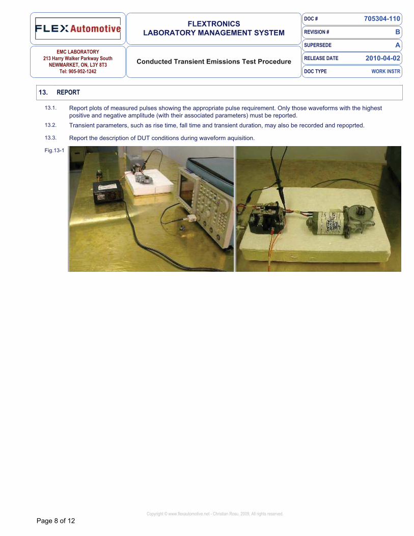
13.1. Report plots of measured pulses showing the appropriate pulse requirement. Only those waveforms with the highest positive and negative amplitude (with their associated parameters) must be reported.
13.2. Transient parameters, such as rise time, fall time and transient duration, may also be recorded and repoprted.
13.3. Report the description of DUT conditions during waveform aquisition.
Fig.13-1

DOC # 705304-110
REVISION # B
SUPERSEDE A
RELEASE DATE 2010-04-02
DOC TYPE WORK INSTR
FLEXTRONICS LABORATORY MANAGEMENT SYSTEM
EMC LABORATORY 213 Harry Walker Parkway South
NEWMARKET, ON, L3Y 8T3 Tel: 905-952-1242
Conducted Transient Emissions Test Procedure
Page 9 of 12Copyright © www.flexautomotive.net - Christian Rosu, 2009, All rights reserved.
14. PROFICIENCY TESTING
14.1. Per LMS011 non-AEMCLAP test methods section, Conducted Transient Emissions ISO 7637-2, DC-I0614; DC-I 1224; ES-EW7T-IA278-AC; GMW3097 (every 6 months).
Fig.14-1

DOC # 705304-110
REVISION # B
SUPERSEDE A
RELEASE DATE 2010-04-02
DOC TYPE WORK INSTR
FLEXTRONICS LABORATORY MANAGEMENT SYSTEM
EMC LABORATORY 213 Harry Walker Parkway South
NEWMARKET, ON, L3Y 8T3 Tel: 905-952-1242
Conducted Transient Emissions Test Procedure
Page 10 of 12Copyright © www.flexautomotive.net - Christian Rosu, 2009, All rights reserved.
15. TRENDS
15.1. Trends are processed via EMC laboratory database to verify the stability of the measurements over time.
Fig.15-1

DOC # 705304-110
REVISION # B
SUPERSEDE A
RELEASE DATE 2010-04-02
DOC TYPE WORK INSTR
FLEXTRONICS LABORATORY MANAGEMENT SYSTEM
EMC LABORATORY 213 Harry Walker Parkway South
NEWMARKET, ON, L3Y 8T3 Tel: 905-952-1242
Conducted Transient Emissions Test Procedure
Page 11 of 12Copyright © www.flexautomotive.net - Christian Rosu, 2009, All rights reserved.
16. DEFINITIONS
16.1. CTE = Conducted Transient Emissions
16.2. EMC = electromagnetic compatibility (ability of equipment or system to function satisfactorily in its electromagnetic environment without introducing intolerable electromagnetic disturbance to anything in that environment)
16.3. EMI = electromagnetic interference (degradation of the performance of equipment, transmission. channel or system caused by an electromagnetic disturbance)
16.4. AN = artificial network (network inserted in the supply leads of an apparatus to be tested that provides, in a given frequency range, a specified load impedance for the measurement of disturbance voltages and isolates the apparatus from the power supply in that frequency range)
16.5. transient (phenomenon or quantity which varies between two consecutive steady states during a time interval which is short compared to the time scale of interest)
16.6. pulse duration (time from the instant the absolute value of the pulse rises above 10 % of the absolute value of the peak amplitude to the instant it falls below 10 % of this)
16.7. pulse rise time (time taken for the absolute value of the pulse to increase from 10 % to 90 % of the absolute value of the peak amplitude) pulse fall time (time taken for the absolute value of the pulse to decrease from 90 % to 10 % of the absolute value of the peak amplitude)
REFERENCES
ISO 7637-2 Second edition Jun 15, 2004 Road vehicles — Electrical disturbances from conduction and coupling —
Part 2: Electrical transient conduction along supply lines only
DC-11224 A Jun 1, 2007 EMC Performance Requirements --- Components
DC-10614 B Dec 1, 2005 EMC Performance Requirements --- Components
CS-11809 May 29, 2009 ELECTRICAL AND EMC PERFORMANCE REQUIREMENTS - E/E COMPONENTS
EMC-CS-2009.1 1 Feb 11, 2010 Electromagnetic Compatibility Specification For Electrical/Electronic Components and Subsystems
ES-XW7T-1A278-AC AC Oct 10, 2003 Component and Subsystem Electromagnetic Compatibility Worldwide Requirements and Test
Procedures
GMW3097 July 2006 General Specification for Electrical/Electronic Components and Subsystems, Electromagnetic Compatibility
SAE J1113-42 Sep 1, 2000 (R) Electromagnetic Compatibility-Component Test Procedure Part 42-Conducted Transient Emissions
LMS011 E Jan 26, 2010 EMC LAB, PROFICIENCY TESTING PROGRAM PROCEDURE
REVISION CHANGES
Jan 15, 2010 A Release Christian Rosu
Apr 2, 2010 B Updated References Christian Rosu

DOC # 705304-110
REVISION # B
SUPERSEDE A
RELEASE DATE 2010-04-02
DOC TYPE WORK INSTR
FLEXTRONICS LABORATORY MANAGEMENT SYSTEM
EMC LABORATORY 213 Harry Walker Parkway South
NEWMARKET, ON, L3Y 8T3 Tel: 905-952-1242
Conducted Transient Emissions Test Procedure
Page 12 of 12Copyright © www.flexautomotive.net - Christian Rosu, 2009, All rights reserved.
END-USER FEEDBACK
very satisfied satisfied neutral dissatisfied very dissatisfied
Please rate your overall satisfaction with this LMS document and input your suggestions or comments. Your opinion is very important for us.
Survey Date


