Superior Broadcast Products - ONLINE...
95
17194 Preston Rd., Suite 102-297 • Dallas, Texas Phone: 972-279-3326 • 800-279-3326 • Fax: 972-473-5958 • 800-644-5958 superiorbroadcastproducts.com Television Transmitters Digital and Analog FM Transmitters Antennas for FM, Television and Microwave Transmission Line Financing and Leasing Available S uperior uperior uperior uperior uperior Br r roadcast oadcast oadcast oadcast oadcast Pr r roducts oducts oducts oducts oducts Power Levels 5 Watts to 20,000 Watts 20 Watts to 30,000 Watts Digital and Analog, All Power Levels Complete Turnkey Installation Available
Transcript of Superior Broadcast Products - ONLINE...

17194 Preston Rd., Suite 102-297 • Dallas, TexasPhone: 972-279-3326 • 800-279-3326 • Fax: 972-473-5958 • 800-644-5958
superiorbroadcastproducts.com
Television TransmittersDigital and Analog
FM Transmitters
Antennas forFM, Television and Microwave
Transmission Line
Financing and Leasing Available
Superior uperior uperior uperior uperior Brrrrroadcast oadcast oadcast oadcast oadcast Prrrrroductsoductsoductsoductsoducts
Power Levels 5 Watts to 20,000 Watts
20 Watts to 30,000 Watts
Digital and Analog, All Power Levels
Complete Turnkey Installation Available


Table of ContentsPackages, Financing, Leasing, Training, Field Services ..................................................................4
Television Transmitters ............................................................................................................. 5-424000 Watt Digital Television Transmitter ...................................................................................5250 Watt Digital Television Transmitter .....................................................................................6125 Watt Digital Television Transmitter ...................................................................................1020,000 Watt UHF Television Transmitter..................................................................................1410,000 Watt UHF Television Transmitter..................................................................................1810,000 Watt Television Transmitter Solid State Television Transmitter ...................................228000 Watt Solid State Television Transmitter ..........................................................................264000 to 6000 Watt Television Transmitters .............................................................................301000 to 3000 Watt Television Transmitters .............................................................................34500 Watt and 1000 Watt VHF Television Transmitters .............................................................38100 Watt UHF or VHF Television Transmitter ...........................................................................42
700 Watt Solid State UHF Amplifier ..............................................................................................44
Antennas .................................................................................................................................. 48-76
Broadcast Exciters ................................................................................................................... 77-8020 Watt Solid State FM Exciter/Transmitter .............................................................................77100 Watt Solid State FM Exciter/Transmitter ...........................................................................78250 Watt Solid State FM Exciter/Transmitter ...........................................................................79500 Watt Solid State FM Amplifier ...........................................................................................80
FM Transmitters....................................................................................................................... 81-8320,000 Watt FM Transmitter ....................................................................................................8112,000 Watt FM Transmitter ....................................................................................................8210,000 FM Transmitter .............................................................................................................83
FM Antennas ............................................................................................................................ 84-85Model Model FMD Broadband Circular Polarized FM Antenna ...............................................84Model FMA High Power Broadband Circular Polarized FM Antenna........................................85
Accessories .....................................................................................................................................89Frequency Agile STL System ..........................................................................................................90High Gain Half Parabolic Antenna and 15 Element 950 MHz Logperiodic Antenna ......................91Combiners, Band Pass and Notch Filters ........................................................................................92Sine Systems Model DAI-2 Dial Up Audio Interface .......................................................................93Gorman-Redlich Model EAS-1 Emergency Alert System Encoder-Decoder ...................................94Microwave Antennas ......................................................................................................................95

4 kW DigitalSuperior uperior uperior uperior uperior Brrrrroadcast oadcast oadcast oadcast oadcast PrrrrroductsoductsoductsoductsoductsQuality Broadcast PQuality Broadcast PQuality Broadcast PQuality Broadcast PQuality Broadcast Products at Rroducts at Rroducts at Rroducts at Rroducts at Reasonable Peasonable Peasonable Peasonable Peasonable Pricesricesricesricesrices
Equipment PEquipment PEquipment PEquipment PEquipment Packackackackackages:ages:ages:ages:ages:Your transmitter, antenna and associated transmissioncomponents can be purchased as a complete package.
Financing or LFinancing or LFinancing or LFinancing or LFinancing or Leasing:easing:easing:easing:easing:We can arrange financing or leasing for your entiretransmitting system.
TTTTTraining:raining:raining:raining:raining:Our expert technical staff will help you with the installation ofyour new transmitter and provide “on the job” training at noadditional cost.
Field Support and SerField Support and SerField Support and SerField Support and SerField Support and Service:vice:vice:vice:vice:Because our television transmitters are manufactured in theDallas, Texas area, we can provide quick turnaround onreplacement parts and modules.
Superior uperior uperior uperior uperior Brrrrroadcast oadcast oadcast oadcast oadcast Prrrrroductsoductsoductsoductsoducts17194 Preston Road, Suite 102-297
Dallas, Texas 75248Ph.: 800/279-3326 • FAX: 800/644-5958 • 972/473-2577

Solid State Television TransmittersQuality Broadcast Products at Reasonable Prices
4000 Watt Digital TV TransmitterSuperior Broadcast Products, a leading manufacturer of low power television transmitters,is now producing Digital Transmitters for the broadcast industry. As with our analogtransmitters, Superior Broadcast Products is committed to producing one of the best HDTVTransmitters ever. SPB now offers both 100% Solid State as well as single tube finalamplifier models. Our 500 Watt model uses the proven design of the TH 347 tube. The4000 Watt model uses the Thales TH 610 Diacrode which provides high gain and efficiencyat an affordable cost. Both transmitters feature ease of adjustments and increased stabilitydue to robust RF circuit design and simplified cooling requirements. The 100% SolidState driver utilizes LDMOS transistors, achieving the high degree of linearity necessaryfor Digital Broadcasting. An industry standard HDTV modulator featuring both linear andnon-linear pre-correction is available in all Superior Broadcast Products Digital Transmitters.
These transmitters comply with allFCC specifications and the ATSCDigital television standards. A highdegree of protection and universalremote control capability are standardfeatures on all our Digital and Analogtransmitters.
The 44 MHz IF Modulation offers:
• ATSC Compatibility
• SMPTE-310M input (ASI inputoption available)
• Front panel indication for powerand input data stream present
• Linear and non-linear pre-correction option available
• External Frequency ReferenceInput to allow precision offsets

Model SS-DT250-UT250 Watt SOLID STATE DIGITAL UHF
TELEVISION TRANSMITTER
Superioruperioruperioruperioruperior Brrrrroadcastoadcastoadcastoadcastoadcast Prrrrroductsoductsoductsoductsoducts17194 Preston Rd. Suite 102-297 Dallas, TX 75248
Phone 972-473-2577 Fax 972-473-2578Sales Support 1-800-279-3326

Description of the Equipment
The SS-DT250-UT is a high quality American made 250 Watt Digital UHF TelevisionTransmitter designed for the 8VSB Format.
The digital SMPTE-310M signal is fed to an 8VSB IF modulator, which contains both linear andnon-linear pre-correction. The output of the modulator is a 44 Mhz IF with a nominal level of -15dBm. This IF signal is then fed to the upconverter, where it is converted and amplified to give anominal on-channel output of +6 dBm.
The output of the upconverter is fed to the driver amplifier, where it is amplified to a nominallevel of +36 dBm and fed to the power amplifier (PA) assembly with its associated powersupplies. The PA amplifier has two gain stages which raise the output power to more than 250Watts, thus compensating for the mask filter, which follows the PA.
The mask filter assembly guarantees spectral compliance for the digital signal.
The SS-DT250-UT has many control and protection features seldom found in comparablypriced equipment:
• Active components are located on printed circuit boards for fast, easy field service.
• All of the metering and control circuitry is built with high precision components.
• Light emitting diodes (LEDs) give a quick, visual indication of the condition of the transmitter.
• The digital panel meters give highly accurate readings of the important voltages, currents,and powers associated with the final amplifier.
• High power components insure that the transmitter can survive adverse conditions.
• All of the major components, such as transformers, capacitors, and power resistors areeasily field replaceable and are readily available from either the original manufacturer or fromSuperior Broadcast Products.

Technical Specifications
250 Watt UHF Transmitter For ATSC Digital Service
Power Output 250 W (average)
Frequency Range Any TV channel within the 470-806 MHz bandincluding standard offsets
Output Impedance 50 Ohms
Output Connector 1-5/8" EIA Flange
Out of Band Emission Meets or Exceeds FCC Requirements
Digital SNR 27 dB Minimum
General Specifications
Driver LDMOS Amplifier
Output Stage LDMOS Amplifier
Maximum Altitude 2500 Meters (8200 Feet)
Ambient Temperature Range -30º C to +50º C
Relative Humidity 0 to 95%, Non-Condensing
Primary Power 220 VAC, 50/60 Hz Nominal
Cooling Forced Air
Dimensions (W x H x D): 55.9 x 176.5 x 81.3 cm (22" x 69.5" x 32")Available in 40” cabinet height (Mask filter isexternal.)

Weight ~160 kg (350 lbs.)
Power Consumption ~1.5 kW Maximum (Channel Dependent)
Heat Load @ Full Output (Typical) 4200 BTU/Hr
Air Conditioning Requirements Based on local environment; consult factory
Additional Options:
AC Surge ProtectorSpare Parts KitRemote ControlDual Exciter Assembly

Model SS-DT125-UT125 Watt SOLID STATE DIGITAL UHF
TELEVISION TRANSMITTER
Model SS-DT125-UT125 Watt SOLID STATE DIGITAL UHF
TELEVISION TRANSMITTER
Superioruperioruperioruperioruperior Brrrrroadcastoadcastoadcastoadcastoadcast Prrrrroductsoductsoductsoductsoducts17194 Preston Rd. Suite 102-297 Dallas, TX 75248
Phone 972-473-2577 Fax 972-473-2578Sales Support 1-800-279-3326

Description of the Equipment
The SS-DT125-UT is a high quality American made 125 Watt Digital UHF TelevisionTransmitter designed for the 8VSB Format.
The digital SMPTE-310M signal is fed to an 8VSB IF modulator, which contains both linear andnon-linear pre-correction. The output of the modulator is a 44 Mhz IF with a nominal level of -15dBm. This IF signal is then fed to the upconverter, where it is converted and amplified to give anominal on-channel output of +6 dBm.
The output of the upconverter is fed to the driver amplifier, where it is amplified to a nominallevel of +30 dBm and fed to the power amplifier (PA) assembly with its associated powersupplies. The PA amplifier has two gain stages which raise the output power to more than 125Watts, thus compensating for the mask filter, which follows the PA.
The mask filter assembly guarantees spectral compliance for the digital signal.
The SS-DT125-UT has many control and protection features seldom found in comparablypriced equipment:
• Active components are located on printed circuit boards for fast, easy field service.
• All of the metering and control circuitry is built with high precision components.
• Light emitting diodes (LEDs) give a quick, visual indication of the condition of the transmitter.
• The digital panel meters give highly accurate readings of the important voltages, currents,and powers associated with the final amplifier.
• High power components insure that the transmitter can survive adverse conditions.
• All of the major components, such as transformers, capacitors, and power resistors areeasily field replaceable and are readily available from either the original manufacturer or fromSuperior Broadcast Products.

Technical Specifications
125 Watt UHF Transmitter For ATSC Digital Service
Power Output 125 W (average)
Frequency Range Any TV channel within the 470-806 MHz bandincluding standard offsets
Output Impedance 50 Ohms
Output Connector 1-5/8" EIA Flange
Out of Band Emission Meets or Exceeds FCC Requirements
Digital SNR 27 dB Minimum
General Specifications
Driver LDMOS Amplifier
Output Stage LDMOS Amplifier
Maximum Altitude 2500 Meters (8200 Feet)
Ambient Temperature Range -30º C to +50º C
Relative Humidity 0 to 95%, Non-Condensing
Primary Power 220 VAC, 50/60 Hz Nominal
Cooling Forced Air
Dimensions (W x H x D): 55.9 x 176.5 x 81.3 cm (22" x 69.5" x 32")Available in 40” cabinet height (Mask filter isexternal.)

Weight ~120 kg (260 lbs.)
Power Consumption <1 Kw Maximum (Channel Dependent)
Heat Load @ Full Output (Typical) 2000 BTU/Hr
Air Conditioning Requirements Based on local environment; consult factory
Additional Options:
AC Surge ProtectorSpare Parts KitRemote ControlDual Exciter Assembly

SuperioruperioruperioruperioruperiorBrrrrroadcastoadcastoadcastoadcastoadcast
PrrrrroductsoductsoductsoductsoductsModel SBP-20000-UT20 KW ANALOG UHF
TELEVISION TRANSMITTER
Superioruperioruperioruperioruperior Brrrrroadcast oadcast oadcast oadcast oadcast Prrrrroductsoductsoductsoductsoducts17194 Preston Rd. Suite 102-297 Dallas, TX 75248
Phone 972-473-2577 Fax 972-473-2578Sales Support 1-800-279-3326

Description of the EquipmentThe SS20000-UT is a high quality American made 20 kilowatt UHF Television Transmitterdesigned for NTSC, PAL or SECAM Formats.
The audio and video signals are fed to the driver assembly, which consists of three stages. Amodulator/upconverter creates on-channel visual and aural carriers at 0 dBm. The on-channel RF is then fed to two identical amplifier chains consisting of 25 Watt LDMOS driveramplifiers which feed 700 Watt LDMOS intermediate power amplifiers (IPA). TheseLDMOS amplifiers provide the necessary drive power to produce a 10 kilowatt output from eachof the two final amplifiers. Each of the final amplifier stages includes a power amplifier (PA)cavity assembly with its associated power supplies and protection circuits. The outputs of thetwo amplifier chains are combined for powers from 15,000-20,000 Watts. The output combiner/filter assembly can be mounted on top of the transmitter; or ceiling or wall mounted.
The SS20000-UT has many control and protection features seldom found in comparably pricedequipment:
• Active components are located on printed circuit boards for fast, easy field service.
• All of the metering and control circuitry is built with precision components.
• Light emitting diodes (LEDs) give a quick, visual indication of the condition of the transmitter.
• Digital panel meters give accurate readings of important voltages, currents, and powersassociated with the IPA and PA.
• Robust power components insure that the transmitter can survive adverse conditions.
• All of the major components, such as transformers, capacitors, and power resistors areeasily field replaceable and are readily available from either the original manufacturer or fromSuperior Broadcast Products.

Technical SpecificationsOutput Specifications
Overall:
Power Capability 20 kW Visual (peak sync) with 2 kW Aural (average)
Frequency Range Any TV channel within the 470-860 MHz band includingstandard offsets
Output Impedance 50 Ohms
Output Connector 3-1/8" EIA Flange (other options available)
Carrier Stability ± 1kHz standard and offset channels
Intercarrier Stability ± 500Hz
Harmonics Products -60dB or better referred to sync peak
Non-Harmonic Spurious Products As per appropriate FCC or CCIR Standard
Video:
Differential Gain 5%
Differential Phase ± 3º
Group Delay As per appropriate FCC or CCIR StandardFrequency Response (Sideband) As per appropriate FCCor CCIR Standard
In Band Intermodulation Products -52dB or better (using three tone test)
Audio:
Frequency Response (Main Channel) ±0.5 dB (50Hz to 15kHz with appropriate de-emphasis)
Pre-emphasis As per appropriate FCC or CCIR Standard
FM Noise -60 dB or better
AM Noise -50 dB or better
Total Harmonic Distortion 0.5% or better
Frequency Deviation Capability ±25 kHz for Monophonic OperationStereo exciter available as option
Input Specifications:
Video Input Impedance / Level 75 Ohms, 1V(p-p)
Audio Input Impedance / Level 600 Ohms balanced, -10 dBm to +10 dBm
AC Line Voltage 208 / 240 VAC ±5%, 3 phase, 60 Hz or380 VAC ±5%, 3 phase, 50 Hz(Specify 50Hz or 60Hz when ordering)Above voltages nominal; all transformers have 6 taps toconform to local requirements.Other primary voltages available

General Specifications:
Cavity Drivers (IPA) 700W LDMOS Amplifiers
Output Stage Two Cavity Amplifiers using TH610 Diacrodes
Cooling Forced Air
Max Altitude 7500 ft (higher altitude operation as option)
Ambient Temperature Range -30º C to +50º C
Ambient Humidity Range 0 - 95% relative humidity without condensation
Dimensions (W x H x D):Cabinet 110" x 71" x 32"Output Filter/Coupler ~40" x 18" x 6"
Weight Approximately 3200 lbs.
Power Consumption (Typical) 48kVA (black picture, 20kW visual, 2 kW aural)
Heat Load @ Full Output 120,000 BTU/Hr
Air Conditioning Requirements Based on local environment; consult factory
Additional Options:
Automatic FSK Station Identifier Input Video Automatic Gain ControlAC Surge Protector Audio ProcessorSpare Tube BTSC Stereo GeneratorSpare Parts Kit Remote ControlVideo Proc/Amp Final Amplifier Bypass Switch

Model SBP-10000UT10 KW ANALOG UHF
TELEVISION TRANSMITTER
Superior uperior uperior uperior uperior Brrrrroadcast oadcast oadcast oadcast oadcast Prrrrroductsoductsoductsoductsoducts
Model SBP-10000UT10 KW ANALOG UHF
TELEVISION TRANSMITTER
Superior uperior uperior uperior uperior Brrrrroadcast oadcast oadcast oadcast oadcast Prrrrroductsoductsoductsoductsoducts17194 Preston Rd. Suite 102-297 Dallas, TX 75248
Phone 972-473-2577 Fax 972-473-2578Customer Support 1-877-224-0849

Description of the EquipmentThe SBP-10000UT is a high quality American made 10 kilowatt UHF Television Transmitterdesigned for NTSC, PAL or SECAM Formats.
The audio and video signals are fed to the driver assembly, which consists of three stages. Amodulator/upconverter creates on-channel visual and aural carriers at 0 dBm. This signal isthen amplified by the 25 Watt driver amplifier and fed to the 700 Watt intermediate poweramplifier (IPA) which provides the necessary drive power to produce a 5-10 kilowatt outputfrom the final amplifier. The final amplifier stage includes a power amplifier (PA) cavity assem-bly with its associated power supplies, a notch filter, and a directional coupler. These compo-nents supply the RF signal to the antenna. Two SBP-10000UT transmitters are operated incombined mode for powers from 10,000-20,000 Watts.
The SBP-10000UT has many control and protection features seldom found in comparablypriced equipment:
• Active components are located on printed circuit boards for fast, easy field service.
• All of the metering and control circuitry is built with precision components.
• Light emitting diodes (LEDs) give a quick, visual indication of the condition of the transmitter.
• Digital panel meters give accurate readings of important voltages, currents, and powersassociated with the IPA and PA.
• Robust power components insure that the transmitter can survive adverse conditions.
• All of the major components, such as transformers, capacitors, and power resistors areeasily field replaceable and are readily available from either the original manufacturer or fromSuperior Broadcast Products.

Technical SpecificationsOutput SpecificationsOverall:Power Capability 10 kW Visual (peak sync) with 1 kW Aural (average)
Frequency Range Any TV channel within the 470-860 MHz band includingstandard offsets
Output Impedance 50 Ohms
Output Connector 3-1/8" EIA Flange (other options available)
Carrier Stability ± 1kHz standard and offset channels
Intercarrier Stability ± 500Hz
Harmonics Products -60dB or better referred to sync peak
Non-Harmonic Spurious Products As per appropriate FCC or CCIR Standard
Video:Differential Gain 5%
Differential Phase ± 3º
Group Delay As per appropriate FCC or CCIR Standard
Frequency Response (Sideband) As per appropriate FCC or CCIR Standard
In Band Intermodulation Products -52dB or better (using three tone test)
Audio:
Frequency Response (Main Channel) ±0.5 dB (50Hz to 15kHz with appropriate de-emphasis)
Pre-emphasis As per appropriate FCC or CCIR Standard
FM Noise -60 dB or better
AM Noise -50 dB or better
Total Harmonic Distortion 0.5% or better
Frequency Deviation Capability ±25 kHz for Monophonic OperationStereo exciter available as option
Input Specifications:Video Input Impedance / Level 75 Ohms, 1V(p-p)
Audio Input Impedance / Level 10k Ohms unbalanced, 140 mV RMS( 600 Ohms balanced, -10 dBm to +10 dBmoption available)
AC Line Voltage 208 / 240 VAC ±5%, 3 phase, 60 Hz or380 VAC ±5%, 3 phase, 50 Hz(Specify 50Hz or 60Hz when ordering)Above voltages nominal; all transformers have 6 tapsto conform to local requirements.Other primary voltages available

General Specifications:Driver 700W LDMOS Amplifier
Output Stage Cavity Amplifier using TH610 Diacrode
Cooling Forced Air
Max Altitude 7500 ft (higher altitude operation as option)
Ambient Temperature Range -30º C to +50º C
Ambient Humidity Range 0 - 95% relative humidity without condensation
Dimensions (W x H x D):Cabinet 55" x 71" x 32"Output Filter/Coupler ~40" x 18" x 6"
Weight Approximately 1600 lbs.
Power Consumption (Typical) 24kVA (black picture, 10kW visual, kW aural)
Heat Load @ Full Output 60,000 BTU/Hr
Air Conditioning Requirements Based on local environment; consult factory
Additional Options:Automatic FSK Station Identifier Input Video Automatic Gain ControlAC Surge Protector Audio ProcessorSpare Tube BTSC Stereo GeneratorSpare Parts Kit Remote ControlVideo Proc/Amp Final Amplifier Bypass Switch

Model SS10000-UT10 KW ANALOG UHF
TELEVISION TRANSMITTER
Superior uperior uperior uperior uperior Brrrrroadcast oadcast oadcast oadcast oadcast Prrrrroductsoductsoductsoductsoducts17194 Preston Rd. Suite 102-297 Dallas, TX 75248
Phone 972-473-2577 Fax 972-473-2578Sales Support 1-800-279-3326

Description of the EquipmentThe SS10000-UT is a high quality American made 10 kilowatt UHF TelevisionTransmitter designed for NTSC, PAL or SECAM Formats.
The audio and video signals are fed to the exciter assembly, which consists oftwo stages. A modulator/upconverter creates on-channel visual and auralcarriers at 0 dBm. This signal is then amplified by 25 Watt LDMOS driveramplifiers (IPA) and fed to multiple 700 Watt LDMOS power amplifiers (PA)which are combined to provide the 10 kilowatt transmitter output power. Theoutput combiner/filter assembly can be mounted on top of the transmitter; orceiling or wall mounted.
The SS10000-UT television transmitter has many control and protection featuresseldom found in comparably priced equipment:
• The driver and all PA amplifiers have circulator isolated outputs for enhancedreliability and performance.
• Active components are located on printed circuit boards for fast, easy fieldservice.
• All of the metering and control circuitry is built with precision components.
• Light emitting diodes (LEDs) give a quick, visual indication of the condition ofthe transmitter.
• Digital panel meters give accurate readings of important voltages, currents,and powers associated with the driver and PA.
• Robust power components insure that the transmitter can survive adverseconditions.
• All of the major components, such as power supplies, combiners, circulators,and fans, are easily field replaceable and are readily available from either theoriginal manufacturer or from Superior Broadcast Products.

Technical Specifications
Output Specifications
Overall:
Power Capability 10 kW Visual (peak sync) with 1 KW Aural (average)
Frequency Range Any TV channel within the 470-860 MHz band includingstandard offsets
Output Impedance 50 Ohms
Output Connector 3 1/8" EIA Flange (other options available)
Carrier Stability ± 1 kHz standard and offset channels
Intercarrier Stability ± 500 Hz
Harmonics Products -60 dB or better referred to sync peak
Non-Harmonic Spurious Products As per appropriate FCC or CCIR Standard
Video:
Differential Gain 5%
Differential Phase ± 3º
Group Delay As per appropriate FCC or CCIR Standard
Frequency Response (Sideband) As per appropriate FCC or CCIR Standard
In Band Intermodulation Products -52 dB or better (using three tone test)
Audio:
Frequency Response (Main Channel) ±0.5 dB (50Hz to 15 kHz with appropriate de-emphasis)
Pre-emphasis As per appropriate FCC or CCIR Standard
FM Noise -60 dB or better
AM Noise -50 dB or better
Total Harmonic Distortion 0.5% or better
Frequency Deviation Capability ±25 kHz for Monophonic OperationStereo exciter available as option
Input Specifications:
Video Input Impedance / Level 75 Ohms, 1V(p-p)
Audio Input Impedance / Level 600 Ohms balanced, -10 dBm to +10 dBm
AC Line Voltage 208 / 240 VAC ±5%, single phase, 60 Hz/50 Hz(Specify 50 Hz or 60 Hz when ordering)

General Specifications:
Drivers 3 x 25 W LDMOS Amplifier
Output Stage Multiple 700 W LDMOS Amplifiers
Cooling Forced Air
Max Altitude 7500 ft (higher altitude operation as option)
Ambient Temperature Range -30º C to +50º C
Ambient Humidity Range 0 - 95% relative humidity without condensation
Dimensions (W x H x D):Cabinet 88" x 69.5" x 32"Output Filter/Coupler Channel dependent; contact factory
Weight ~4100 lbs. + 270 lbs., (filter weight channel dependent)
Power Consumption (Typical) 40 kVA (black picture, 10 kW visual, 1 kW aural)
Heat Load @ Full Output 81,000 BTU/Hr
Air Conditioning Requirements Based on local environment; consult factory
Additional Options:
Automatic FSK Station Identifier Input Video Automatic Gain ControlAC Surge Protector Audio ProcessorSpare Tube BTSC Stereo GeneratorSpare Parts Kit Remote ControlVideo Proc/Amp Dual Exciter Assembly

Model SS8000-UT8 KW ANALOG UHF
TELEVISION TRANSMITTER
Superioruperioruperioruperioruperior Brrrrroadcastoadcastoadcastoadcastoadcast Prrrrroductsoductsoductsoductsoducts17194 Preston Rd. Suite 102-297 Dallas, TX 75248
Phone 972-473-2577 Fax 972-473-2578Sales Support 1-800-279-3326

Description of the EquipmentThe SS8000-UT is a high quality American made 8 kilowatt UHF Television Transmitterdesigned for NTSC, PAL or SECAM Formats.
The audio and video signals are fed to the exciter assembly, which consists of two stages. Amodulator/upconverter creates on-channel visual and aural carriers at 0 dBm. This signal isthen amplified by the 25 Watt driver amplifier and fed to multiple 700 Watt power amplifiers(PA) which are combined to provide the 8 kilowatt transmitter output power. The combinedoutput is fed to a notch/bandpass filter and a directional coupler. These components supply theRF signal to the antenna.
The SS8000-UT has many control and protection features seldom found in comparably pricedequipment:
• The driver and all PA amplifiers have circulator isolated outputs for enhanced reliability andperformance.
• Active components are located on printed circuit boards for fast, easy field service.
• All of the metering and control circuitry is built with precision components.
• Light emitting diodes (LEDs) give a quick, visual indication of the condition of the transmitter.
• Digital panel meters give accurate readings of important voltages, currents, and powersassociated with the driver and PA.
• Robust power components insure that the transmitter can survive adverse conditions.
• All of the major components, such as power supplies, combiners, circulators, and fans, areeasily field replaceable and are readily available from either the original manufacturer or fromSuperior Broadcast Products.

Technical SpecificationsOutput Specifications
Overall:
Power Capability 8 kW Visual (peak sync) with 800 W Aural (average)
Frequency Range Any TV channel within the 470-860 MHz band includingstandard offsets
Output Impedance 50 Ohms
Output Connector 3-1/8" EIA Flange (other options available)
Carrier Stability ± 1 kHz standard and offset channels
Intercarrier Stability ± 500 Hz
Harmonics Products -60 dB or better referred to sync peak
Non-Harmonic Spurious Products As per appropriate FCC or CCIR Standard
Video:
Differential Gain 5%
Differential Phase ± 3º
Group Delay As per appropriate FCC or CCIR Standard
Frequency Response (Sideband) As per appropriate FCC or CCIR Standard
In Band Intermodulation Products -52 dB or better (using three tone test)
Audio:
Frequency Response (Main Channel) ±0.5 dB (50Hz to 15 kHz with appropriate de-emphasis)
Pre-emphasis As per appropriate FCC or CCIR Standard
FM Noise -60 dB or better
AM Noise -50 dB or better
Total Harmonic Distortion 0.5% or better
Frequency Deviation Capability ±25 kHz for Monophonic OperationStereo exciter available as option
Input Specifications:
Video Input Impedance / Level 75 Ohms, 1V(p-p)
Audio Input Impedance / Level 10k Ohms unbalanced, 140 mV RMS (600 Ohms balanced, -10dBm to +10 dBm option available)
AC Line Voltage 208 / 240 VAC ±5%, single phase, 60 Hz/50 Hz(Specify 50 Hz or 60 Hz when ordering)

General Specifications:
Driver 25 W LDMOS Amplifier
Output Stage 12 X 700 W LDMOS Amplifiers
Cooling Forced Air
Max Altitude 7500 ft (higher altitude operation as option)
Ambient Temperature Range -30º C to +50º C
Ambient Humidity Range 0 - 95% relative humidity without condensation
Dimensions (W x H x D):Cabinet 44" x 69.5" x 32"Output Filter/Coupler Channel dependent; contact factory
Weight ~1470 lbs. + 170 lbs. filter
Power Consumption (Typical) 24 kVA black picture, 8 kW visual, 400W aural)
Heat Load @ Full Output 60,000 BTU/Hr
Air Conditioning Requirements Based on local environment; consult factory
Additional Options:
Automatic FSK Station Identifier Input Video Automatic Gain ControlAC Surge Protector Audio ProcessorSpare Tube BTSC Stereo GeneratorSpare Parts Kit Remote ControlVideo Proc/Amp Dual Exciter Assembly

Superioruperioruperioruperioruperior Brrrrroadcast oadcast oadcast oadcast oadcast Prrrrroductsoductsoductsoductsoducts
Model SS4000-UT and Model SS6000-UT4 and 6 KW ANALOG UHF
TELEVISION TRANSMITTERS
Superioruperioruperioruperioruperior Brrrrroadcast oadcast oadcast oadcast oadcast Prrrrroductsoductsoductsoductsoducts17194 Preston Rd. Suite 102-297 Dallas, TX 75248
Phone 972-473-2577 Fax 972-473-2578Sales Support 1-800-279-3326

Description of the EquipmentThe SS4000-UT and SS6000-UT are high quality American made 4 and 6 kilowatt UHF Televi-sion Transmitters designed for NTSC, PAL or SECAM Formats.
The audio and video signals are fed to the exciter assembly, which consists of two stages. Amodulator/upconverter creates on-channel visual and aural carriers at 0 dBm. This signal isthen amplified by the 25 Watt driver amplifier and fed to multiple 700 Watt power amplifiers(PA) which are combined to provide the 4 to 6 kilowatt transmitter output power. The combinedoutput is fed to a notch/bandpass filter and a directional coupler. These components supply theRF signal to the antenna.
The SS4000-UT and SS6000-UT have many control and protection features seldom found incomparably priced equipment:
• The driver and all PA amplifiers have circulator isolated outputs for enhanced reliability andperformance.
• Active components are located on printed circuit boards for fast, easy field service.
• All of the metering and control circuitry is built with precision components.
• Light emitting diodes (LEDs) give a quick, visual indication of the condition of the transmitter.
• Digital panel meters give accurate readings of important voltages, currents, and powersassociated with the driver and PA.
• Robust power components insure that the transmitter can survive adverse conditions.
• All of the major components, such as power supplies, combiners, circulators, and fans, areeasily field replaceable and are readily available from either the original manufacturer or fromSuperior Broadcast Products.

Technical SpecificationsOutput Specifications
Overall:
Power Capability 4 – 6 kW Visual (peak sync) with 400 – 600 W Aural (average)
Frequency Range Any TV channel within the 470-860 MHz band including stan-dard offsets
Output Impedance 50 Ohms
Output Connector 1-5/8" EIA Flange (other options available)
Carrier Stability ± 1 kHz standard and offset channels
Intercarrier Stability ± 500 Hz
Harmonics Products -60 dB or better referred to sync peak
Non-Harmonic Spurious ProductsAs per appropriate FCC or CCIR Standard
Video:
Differential Gain 5%
Differential Phase ± 3ºGroup Delay
As per appropriate FCC or CCIR StandardFrequency Response (Sideband) As per appropriate FCC or CCIR Standard
In Band Intermodulation Products -52 dB or better (using three tone test)
Audio:
Frequency Response (Main Channel) ±0.5 dB (50Hz to 15 kHz with appropriate de-emphasis)
Pre-emphasis As per appropriate FCC or CCIR Standard
FM Noise -60 dB or better
AM Noise -50 dB or better
Total Harmonic Distortion 0.5% or better
Frequency Deviation Capability ±25 kHz for Monophonic OperationStereo exciter available as option
Input Specifications:
Video Input Impedance / Level 75 Ohms, 1V(p-p)
Audio Input Impedance / Level 10k Ohms unbalanced, 140 mV RMS(600 Ohms balanced, -10 dBm to +10 dBm option available)
AC Line Voltage 208 / 240 VAC ±5%, single phase, 60 Hz/50 Hz(Specify 50 Hz or 60 Hz when ordering)

General Specifications:
Driver 25 W LDMOS Amplifier
Output Stage Multiple 700 W LDMOS Amplifiers (10 for 6 kW, 8 for 4 kW)
Cooling Forced Air
Max Altitude 7500 ft (higher altitude operation as option)
Ambient Temperature Range -30º C to +50º C
Ambient Humidity Range 0 - 95% relative humidity without condensation
Dimensions (W x H x D):Cabinet 44" x 69.5" x 32"Output Filter/Coupler Channel dependent; contact factory
Weight ~1150 lbs. + 170 lbs. filter (6kW),~1000 lbs. + 150 lbs. filter (4kW)
Power Consumption (Typical) 18 kVA (6 kW; black picture, 6 kW visual, 30 0W aural)12 kVA (4 kW; black picture, 4 kW visual, 200 W aural)
Heat Load @ Full Output 45,000 BTU/Hr (6 kW), 30,000 BTU/Hr (4 kW)
Air Conditioning Requirements Based on local environment; consult factory
Additional Options:
Automatic FSK Station Identifier Input Video Automatic Gain ControlAC Surge Protector Audio ProcessorSpare Tube BTSC Stereo GeneratorSpare Parts Kit Remote ControlVideo Proc/Amp Dual Exciter Assembly
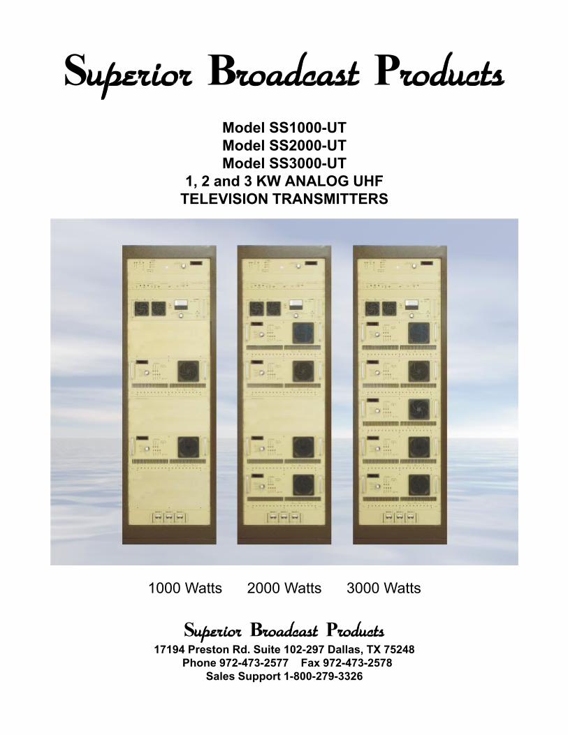
Superior uperior uperior uperior uperior Brrrrroadcast oadcast oadcast oadcast oadcast PrrrrroductsoductsoductsoductsoductsModel SS1000-UTModel SS2000-UTModel SS3000-UT
1, 2 and 3 KW ANALOG UHFTELEVISION TRANSMITTERS
1000 Watts 2000 Watts 3000 Watts
Superioruperioruperioruperioruperior Brrrrroadcastoadcastoadcastoadcastoadcast Prrrrroductsoductsoductsoductsoducts17194 Preston Rd. Suite 102-297 Dallas, TX 75248
Phone 972-473-2577 Fax 972-473-2578Sales Support 1-800-279-3326

Description of the EquipmentThe SS1000-UT, SS2000-UT and SS3000-UT are high quality American made 1, 2 and 3kilowatt UHF Television Transmitters designed for NTSC, PAL or SECAM Formats.
The audio and video signals are fed to the exciter assembly, which consists of two stages. Amodulator/upconverter creates on-channel visual and aural carriers at 0 dBm. This signal isthen amplified by the 25 Watt driver amplifier and fed to multiple 700 Watt power amplifiers(PA) which are combined to provide the appropriate transmitter output power. The combinedoutput is fed to a notch/bandpass filter and a directional coupler. These components supply theRF signal to the antenna.
The SS1000-UT, SS2000_UT and SS3000-UT have many control and protection featuresseldom found in comparably priced equipment:
• The driver and all PA amplifiers have circulator isolated outputs for enhanced reliability andperformance.
• Active components are located on printed circuit boards for fast, easy field service.
• All of the metering and control circuitry is built with precision components.
• Light emitting diodes (LEDs) give a quick, visual indication of the condition of the transmitter.
• Digital panel meters give accurate readings of important voltages, currents, and powersassociated with the driver and PA.
• Robust power components insure that the transmitter can survive adverse conditions.
• All of the major components, such as power supplies, combiners, circulators, and fans, areeasily field replaceable and are readily available from either the original manufacturer or fromSuperior Broadcast Products.

Technical SpecificationsOutput Specifications
Overall:
Power Capability 1-3 kW Visual (peak sync) with 100 – 300 W Aural (aver-age)
Frequency Range Any TV channel within the 470-860 MHz band includingstandard offsets
Output Impedance 50 Ohms
Output Connector 7/8" EIA Flange (1 and 2 kW), 1-5/8” EIA Flange (3 kW)(other options available)
Carrier Stability ± 1 kHz standard and offset channels
Intercarrier Stability ± 500 Hz
Harmonics Products -60 dB or better referred to sync peak
Non-Harmonic Spurious ProductsAs per appropriate FCC or CCIR Standard
Video:
Differential Gain 5%
Differential Phase ± 3ºGroup Delay
As per appropriate FCC or CCIR StandardFrequency Response (Sideband) As per appropriate FCC or CCIR Standard
In Band Intermodulation Products -52 dB or better (using three tone test)
Audio:
Frequency Response (Main Channel) ±0.5 dB (50Hz to 15 kHz with appropriate de-emphasis)
Pre-emphasis As per appropriate FCC or CCIR Standard
FM Noise -60 dB or better
AM Noise -50 dB or better
Total Harmonic Distortion 0.5% or better
Frequency Deviation Capability±25 kHz for Monophonic OperationStereo exciter available as option
Input Specifications:
Video Input Impedance / Level 75 Ohms, 1V(p-p)
Audio Input Impedance / Level 10k Ohms unbalanced, 140 mV RMS(600 Ohms balanced, -10 dBm to +10 dBm option available)
AC Line Voltage 208 / 240 VAC ±5%, single phase, 60 Hz/50 Hz(Specify 50 Hz or 60 Hz when ordering)

General Specifications:
Driver 25 W LDMOS Amplifier
Output Stage Multiple 700 W LDMOS Amplifiers(2 for kW, 4 for 2 kW, 5 for 3 kW)
Cooling Forced Air
Max Altitude 7500 ft (higher altitude operation as option)
Ambient Temperature Range -30º C to +50º C
Ambient Humidity Range 0 - 95% relative humidity without condensation
Dimensions (W x H x D):Cabinet 44" x 69.5" x 32"Output Filter/Coupler Internal for 1 kW and 2 kW; 22 “ x 16” x 26” for 3 kW
Weight ~310 lbs. (1 kW),~450 lbs. (2kW)~525 lbs. + 80 lbs. filter (3kW)
Power Consumption (Typical) ~3.8 kVA (1 kW; black picture, 1 kW peak visual, 100 Waural)
~6.5 kVA (2 kW; black picture, 2 kW peak visual, 200Waural)
~9 kVA (3 kW; black picture, 3 kW peak visual, 300 W aural)
Heat Load @ Full Output (Typical) 7500 BTU/Hr (1 kW),15,000 BTU/Hr (2 kW),22,500 BTU/Hr (3 kW)
Air Conditioning Requirements Based on local environment; consult factory
Additional Options:
Automatic FSK Station Identifier Input Video Automatic Gain ControlAC Surge Protector Audio ProcessorSpare Tube BTSC Stereo GeneratorSpare Parts Kit Remote ControlVideo Proc/Amp Dual Exciter Assemblyl

Model SS500-VTModel SS1000-VT
500 Watt and 1000 Watt VHFTELEVISION TRANSMITTERS
Superioruperioruperioruperioruperior Brrrrroadcast oadcast oadcast oadcast oadcast Prrrrroductsoductsoductsoductsoducts17194 Preston Rd. Suite 102-297 Dallas, TX 75248
Phone 972-473-2577 Fax 972-473-2578Sales Support 1-800-279-3326

Description of the EquipmentThe SS500-VT and SS1000-V are high quality American made 500 and 1000 Watt VHFTelevision Transmitters designed for NTSC, PAL or SECAM Formats.
The audio and video signals are fed to the exciter assembly, which consists of two stages. Amodulator/upconverter creates on-channel visual and aural carriers at 0 dBm. This signal isthen amplified by the 25 Watt driver amplifier and fed to multiple 700 Watt power amplifiers(PA) which are combined to provide the appropriate transmitter output power. The combinedoutput is fed to a notch/bandpass filter and a directional coupler. These components supply theRF signal to the antenna.
The SBP-SSTVV-500 and SBP-SSTVV-1000 have many control and protection featuresseldom found in comparably priced equipment:
• The driver and all PA amplifiers have circulator isolated outputs for enhanced reliability andperformance.
• Active components are located on printed circuit boards for fast, easy field service.
• All of the metering and control circuitry is built with precision components.
• Light emitting diodes (LEDs) give a quick, visual indication of the condition of the transmitter.
• Digital panel meters give accurate readings of important voltages, currents, and powersassociated with the driver and PA.
• Robust power components insure that the transmitter can survive adverse conditions.
• All of the major components, such as power supplies, combiners, circulators, and fans, areeasily field replaceable and are readily available from either the original manufacturer or fromSuperior Broadcast Products.

Technical SpecificationsOutput SpecificationsOverall:Power Capability 500 W Visual (peak sync) with 50 W Aural (average)
1000 W Visual (peak sync) with 100 W Aural (average)Frequency Range Available on any TV channel (including standard
offsetts) within:Band I (VHF-LO)Band I I (VHF-M)Band I I I (VHF-HI)
Specify Band and Channel when ordering
Output Impedance 50 OhmsOutput Connector 7/8" EIA Flange
(other options available)
Carrier Stability ± 1 kHz standard and offset channels
Intercarrier Stability ± 500 Hz
Harmonics Products -60 dB or better referred to sync peak
Non-Harmonic Spurious Products As per appropriate FCC or CCIR Standard
Video:Differential Gain 5%
Differential Phase ± 3º
Group Delay As per appropriate FCC or CCIR Standard
Frequency Response (Sideband) As per appropriate FCC or CCIR Standard
In Band Intermodulation Products -52 dB or better (using three tone test)
Audio:
Frequency Response (Main Channel) ±0.5 dB (50Hz to 15 kHz with appropriate de-emphasis)
Pre-emphasis As per appropriate FCC or CCIR Standard
FM Noise -60 dB or better
AM Noise -50 dB or better
Total Harmonic Distortion 0.5% or better
Frequency Deviation Capability ±25 kHz for Monophonic OperationStereo exciter available as option
Input Specifications:Video Input Impedance / Level 75 Ohms, 1V(p-p)Audio Input Impedance / Level 10k Ohms unbalanced, 140 mV RMS
(600 Ohms balanced, -10 dBm to +10 dBmoption available)
AC Line Voltage 208 / 240 VAC ±5%, single phase, 60 Hz/50 Hz(Specify 50 Hz or 60 Hz when ordering)

General Specifications:Driver 25 W LDMOS AmplifierOutput Stage Multiple 700 W LDMOS Amplifiers
(1 for 500 W, 2 for 1000 W)
Cooling Forced Air
Max Altitude 7500 ft (higher altitude operation as option)
Ambient Temperature Range -30º C to +50º C
Ambient Humidity Range 0 - 95% relative humidity without condensation
Dimensions (W x H x D): 22" x 48.3" x 32"
Internal for 1 kW and 2 kW; 22 “ x 22” x 26” for 3 kW
Weight ~200 lbs. (500 W),~270 lbs. 1000 W)
Power Consumption (Typical) ~1.9 kVA 500 W (500 W peak visual w/ black picture,50 W aural)~3.8 kVA 1000 W (1000 W peak visual w/ blackpicture, 100 W aural))
Heat Load @ Full Output (Typical) 3750 BTU/Hr (500 W),7500 BTU/Hr (1000 W),
Air Conditioning Requirements Based on local environment; consult factory
Additional Options:Automatic FSK Station Identifier Input Video Automatic Gain ControlAC Surge Protector Audio ProcessorSpare Tube BTSC Stereo GeneratorSpare Parts Kit Remote ControlVideo Proc/Amp Dual Exciter Assembly

Superioruperioruperioruperioruperior Brrrrroadcast oadcast oadcast oadcast oadcast Prrrrroductsoductsoductsoductsoducts17194 Preston Rd. Suite 102-297 Dallas, TX 75248
Phone 972-473-2577 Fax 972-473-2578Sales Support 1-800-279-3326

Description of the Equipment
The SBP-SSTV -100W Series is available in both UHF and VHF versions. This is a high quality American made 100Watt Television Transmitter designed for NTSC, PAL or SECAM Formats.
The audio and video signals are fed to the exciter assembly, which consists of two stages. A modulator/ upconverterwhich creates on-channel visual and aural carriers at 0 dBm. In the UHF version this signal is then amplified by a 25Watt LDMOS driver (IPA) and fed to an 150 Watt LDMOS power amplifier (PA) to provide the 100 Watt transmitteroutput power. The VHF version utilizes MOS transistors in the IPA and PA stages. The output filter assembly anddirectional coupler are mounted inside the transmitter cabinet.
This television transmitter has many control and protection features seldom found in comparably priced equipment:
• The PA amplifier has a circulator isolated output for enhanced reliability and performance.
• Active components are located on printed circuit boards for fast, easy field service.
• All of the metering and control circuitry is built with precision components.
• Light emitting diodes (LEDs) give a quick, visual indication of the condition of the transmitter.
• A front panel meter gives accurate readings of important voltages, currents, and powers associated with the driverand PA.
• Robust power components insure that the transmitter can survive adverse conditions.
• All of the major components, such as power supplies, circulators, and fans, are easily field replaceable and arereadily available from either the original manufacturer or from Superior Broadcast Products.
Technical Specifications
Power Capability 100 W Visual (peak sync) with 10 W Aural (average)
Frequency Range Any TV channel within the following bands including standard offsetsUHF 470-806 Mhz, VHF-HI 174-216 Mhz, VHF-LO 54-88 MHz
Carrier Stability ± 1 kHz standard and offset channels
Intercarrier Stability ± 500 Hz
Harmonics Products -60 dB or better referred to sync peak
Non-Harmonic Spurious ProductsAs per appropriate FCC or CCIR Standard
AC Line Voltage
120/ 240 VAC, single phase, 60 Hz/50 Hz(Specify 50 Hz or 60 Hz when ordering)
Driver 25 W LDMOS Amplifier (UHF), 50 W MOS (VHF)
Output Stage 150 W LDMOS Amplifier (UHF), 200 W MOS (VHF)
Dimensions (W x H x D): 22” x 20” x 20”
Weight ~70 lb.
Additional Options:
Automatic FSK Station Identifier Input Video Automatic Gain ControlAC Surge Protector Audio ProcessorSpare Tube BTSC Stereo GeneratorSpare Parts Kit Remote ControlVideo Proc/Amp Dual Exciter Assembly

Model SS700-U700 Watt Solid State
UHF Amplifier
Model SS700-U700 Watt Solid State
UHF Amplifier
Superioruperioruperioruperioruperior Brrrrroadcastoadcastoadcastoadcastoadcast Prrrrroductsoductsoductsoductsoducts17194 Preston Rd. Suite 102-297 Dallas, TX 75248
Phone 972-473-2577 Fax 972-473-2578Sales Support 1-800-279-3326

Description of the Equipment
The SS700U RF Amplifier is a fully self-contained assembly designed to be mounted in a stan-dard 19 inch equipment rack with other SS700U amplifiers and the appropriate driver, and inter-face assemblies. It can be operated as either a stand-alone power amplifier or as part of a largersystem. The amplifier can produce more than 700W CW with relatively low drive level. It fea-tures self-contained monitoring and protection so as to allow for a variety of combining schemes.The SS700U is a linear and broadband device suitable for both analog and digital service. Al-though initially designed for broadcast service, its robust and predictable performance makes iteasily adaptable to industrial and scientific applications as well.
All active components are solid state and conservatively rated to insure long-life and trouble-freeoperation. Virtually all of the metering and control circuitry is built with precision components,eliminating the need for numerous adjustments and compensating circuitry. Light emitting diodes(LEDs) give a quick, visual indication of the condition of the equipment and, in most instances, willhelp isolate a fault to a particular area within the circuitry. The digital panel meter gives accuratereadings of the important voltages and currents associated with the power amplifier. In addition tothe extensive protection circuitry, high power components have been utilized to ensure that theequipment will give good service under adverse conditions.
General Technical Description
The SS700U is a highly integrated system consisting of very few discrete components and arelatively simple interconnect harness. A single control and protection board, stripline input andoutput boards, and pallet amplifiers are assembled in a two-sided chassis to deliver excellentperformance and reliability in a compact form. The entire amplifier may be easily shipped iffactory service is required; however, a technically competent person can service the unit in thefield with the appropriate tools and test equipment.
The amplifier is available in either a horizontal or a vertical mounting orientation. The front panelcontrols and labeling are correct for each orientation, however the internal configuration isunchanged. The vertically oriented model requires a mounting adapter for installation in a standardequipment rack.
700 Watt PA
The 700 Watt amplifier is a self-contained assembly requiring 220 VAC main power, +24VDCcontrol voltage, and a +24VDC “ON” command to function. It is capable of more than 700Watts CW. The main +30VDC switching power supply is contained in the assembly along withthe amplifier cards, splitting / combining boards, cooling fans, amplifier protection board, SWRsensor and front panel monitoring. This assembly uses four pallet amplifier cards mounted onthe main heatsink located in the RF section of the cabinet, along with a microstrip splitter and amicrostrip combiner. The amplifier features a built in circulator with a 500 Watt load to protectagainst bad load conditions. The power supply, control and protection circuits are mounted inthe opposite side of the cabinet. The gain of this assembly is nominally 25dB with 50 Ohminput and output impedances.

Amplifier Stage
Each of the four amplifier cards in the SS700U has two LDMOS dual transistors operatingin a class “AB” mode for the best linearity. Each amplifier card has a temperature com-pensated, regulated bias supplies for each transistor.
The amplifier cards are broadband to eliminate the need for tuning or alignment. Thecards have a 50 Ohm input and output impedance.
Specifications
700 Watt Solid State UHF Amplifier
Power Output 700 W (peak), 500 W (CW)
Frequency Range 480 - 806 MHz in 3 subbands(Other UHF/VHF bands available)
Output Impedance 50 Ohms
Output Connector “N” female
Driver LDMOS Dual Transistor
Output Stage 8 x LDMOS Dual Transistors
Maximum Altitude 3600 Meters (12,000 Feet)
Ambient Temperature Range -15º C to +40º C (full performance)-30º C to +50º C (reduced output performance)
Relative Humidity 0 to 95%, Non-Condensing
Primary Power 220 VAC, 50/60 Hz Nominal
Cooling Forced Air
Dimensions (W x H x D): 48.3 x 22.2 x 61 cm (19" x 8.75" x 24")
Weight ~33kg (72 lbs.)
Power Consumption ~1.5 kW Maximum (Channel Dependent)
Heat Load @ Full Output (Typical) 4200 BTU/Hr
Additional Options:
Similar Amplifiers are available across the UHF/VHF range

PA Side• Dual High Performance Fans• Circulator Isolated Output• 500 Watt Circulator Load• Isolated Input/Output Combining• Large Capacity Heat Sink• Individually Fused Amplifiers
Control Side• Digital Metering• 1500 Watt Main Supply
(Higher Capacity Supplies Available)• Protection:
Over VoltageUnder VoltageOver CurrentSWRHeat Sink SensorCooling Air Flow Sensor

Superior uperior uperior uperior uperior Brrrrroadcast oadcast oadcast oadcast oadcast PrrrrroductsoductsoductsoductsoductsBroadband UHF TV Panel Antenna


The Television 1900 Series are Precision-Designedand built low power antenna. These quality highperformance antennas are designed to handle up to 10kW of average input power. The LP-1900 is available intwo patterns: an omnioid (gain of 1.7) and a cardioid (gainof 1.9). The antenna is available in sizes from 4 to 24bays, in one bay increments.
The LP-1900 Series is designed to the same highstandards as our ChromaStarTM and DigilogTM seriesof antennas. For lower power STA or class A applicationsthat need a low weight profile antenna, the LP-1900 isyour first choice. Low power does not mean lowperformance- Each lightweight LP-1900 series uses ourpatent-pending EmagnexTM coupling structures, toensure excellent pattern stability over the entiretransmitted signal bandwidth. This ensures a lowV.S.W.R. of no more than 1.10:1.0 over the entire band.Each LP-1900 antenna is end fed with a 3-1/8” EIA inputflange which allows the best power rating’s in this classof antenna.
The LpStarTM 1900 Series is an exceptionalvalue for standby, low-power or STA applications. Ourhighly automated manufacturing facility offers quickdelivery times on these value packed antennas. Considerthe LP-1900 series for a back up antenna.
Rugged construction and easy to install are two pointsyou will remember the most about this antenna after it isinstalled. The LP-1900 is constructed from a high-strengthpassivated aluminum pylon. Standard mounting bracketsare provided with the antenna. The small lightweightstructure of the antenna allows quick installation usingsmaller rigging equipment.
FEATURES & BENEFITS
• Up to 4 kW average input powerrating
• Very low weight and windprofile
• Designed for Single ChannelDTV or NTSC operation
• End fed design with 3-1/8” EIAinput flange
• Multi Channel Models Available
• Easy to install - standardmounting brackets
SBP-RFT Single and Multi Channel UHFDTV and NTSC Television Antennas for
Power Input of up to 10 KW


SBP-RFT Single and Multi Channel UHF BroadcastAntennas. Top Mounted and Side Mounted Models
with power levels up to 100KW
SBP-RFT Television Antennas are Precision-De-signed and Built DTV/Analog television broadcast antennas from theRF Technologies Corporation’s Antenna Systems Group. These high-performance antennas are designed handle up to 100 kilowatts ofaverage input power. The antenna is available in 4 to 32 bay configu-rations with a full 12 mHz of bandwidth and is designed for eithersingle or dual adjacent channel applications. The DL-2030 is a greatchoice for initial STA operation, or as use as a standby antenna. The2030 is perfect to mount on top of STL towers, or on high rise build-ings.
Designed to Meet Your NeedsThe robust design of the DigiLogTM antenna design ensures excellenttransmission linearity, essential for high-quality DTV or analog broad-casting. The DL-2030 is available in a low ripple omni-directional pat-tern or in a wide variety of directional patterns. In addition, the beamtilt and null fill of the antenna are built to your exact specifications. Itssuperb mechanical design ensures optimum performance and struc-tural integrity while at the same time presenting a very low weight andwind load signature. An 8 level DL-2030 antenna can provide up to200 kW of DTV ERP (narrow cardioid pattern).
Constructed with Efficiency in MindThe DigiLogTM Top-Mounted antenna is constructed with a high-strength strength passivated Aluminum pylon. This Transverse Elec-tromagnetic, (TEM), Mode pylon is designed to be mounted on virtu-ally any tower or roof support structure. Each radiating element or slotalong the aperture of the antenna is equipped with RFT’s patent-pend-ing high efficiency broadband EmagnexTM coupling structures to effi-ciently and smoothly transmit a high-quality, low time delay signal.
Fully ProtectedThe DigiLogTM Series antenna is fully protected by a high-densitypolyethylene ultra low-loss radome and is stabilized against degrada-tion from U.V. radiation. In addition, every portion of the antennathroughout is firmly bonded to DC ground, ensuring enhanced protec-tion of the antenna and transmitting equipment during lightning storms.
FEATURES & BENEFITS• 10 kW average input power
rating
• Designed for Single or Adjacentdual channel operation
• Lightweight - low wind area topmount design
• Center fed for optimal DTVoperation
• Rugged full radome design onon high power modules
• Excellent pattern stability overfull 12 MHz bandwidth
• Top Mount or Side Mount Anten-nas available
• 10KW to 100 KW input powermodels
• 10 Standard Patterns - orwe will customize a pattern tofit your needs.

Superior uperior uperior uperior uperior Brrrrroadcast oadcast oadcast oadcast oadcast Prrrrroductsoductsoductsoductsoducts

15 Element UHF log-periodicAntenna. Ideal transmitting
and receiving antenna.Enclosed in a radome forprotection from weather
SpecificationsModel ALP-720Average Gain 8.5dBdHorizontal beam width at -3dB 27 deg.Vertical beam width at -3dB 36 deg.VSWR Better than 1:3:1Bandwidth 470 - 860 MHzPolarization Horizontal or VerticalImpedance 50 OhmConnector “N” FemaleMaximum power input 100 WattsWeight 30 lbsWind load 27 lbs.Lightning Protection DC GroundMaterials Elements Aluminum Dipoles
Superior uperior uperior uperior uperior Brrrrroadcast oadcast oadcast oadcast oadcast PrrrrroductsoductsoductsoductsoductsUHF High Gain 14 dBd
Yagi Transmit andReceive Antennas
SpecificationsModel AST-330Average Gain 14 dBdHorizontal beam width at -3dB 25 deg.Vertical beam width at -3dB 33 deg.VSWR Better than 1:3:1Bandwidth 20 MHzPolarization Horizontal or VerticalImpedance 50 OhmConnector “N” FemaleMaximum power input 200 WattsPower 200 WattsWeight 12 lbsWind load 18 lbs.Mounting Bracket for 1 to 2.5 inches pipeConstruction Elements treated aluminum
Brackets GalvanizedBolts Stainless Steel
Frequency Band Channel 144 - 69

Superior uperior uperior uperior uperior Brrrrroadcast oadcast oadcast oadcast oadcast Prrrrroductsoductsoductsoductsoducts20 Watt Solid State FM Exciter/Transmitter
ESVA 20 FM BROADCAST EXCITERTechnical Features
Superioruperioruperioruperioruperior Brrrrroadcastoadcastoadcastoadcastoadcast Prrrrroductsoductsoductsoductsoducts
FREQUENCY RANGE 87.5 ÷ 108 MHzMODULATION FMEMISSION CLASS F3EVCO TUNING 25 MHzFREQUENCY STABILITY ± 2.5 ppmSYNTHESIZER STEP 100KHz opz. 10KHzPOWER OUTPUT 0 ÷ 22 WattsSPURIOUS EMISSION < - 80 dB or betterHARMONIC EMISSION < - 70 dBSTEREO SEPARATION > 55 dB @ 1KHz (typ. 60dB)DISTORTION < 0.1 % (typ. 0.06%) @ 1KHz BASE BAND 30 Hz ÷ 60 KHz within 0.15 dBUNWEIGHTED S/N RATIO >80 dB (30Hz ÷ 15KHz 50 µS RMS)ASYNCHRONOUS AM S/N Ratio > 70 dB Ref. 100% AM 400HzSYNCHRONOUS AM S/N Ratio > 65 dB with FM @ 75KHz @400HzPRE-EMPHASIS 50 OR 75 µS int. selectableRF OUT CONNECTOR N-F 50 OhmMPX INPUT CONNECTOR BNC-FMPX INPUT IMPEDANCE 2 KOhm SCA INPUTCONNECTOR 3 BNC-FCOOLING Convection for RF PA and a little fan for insideOP.TEMPERATURE RANGE 0 ÷ +45 °CMAXIMUM HUMIDITY 90 %AC SUPPLY 100 ÷ 240 VAC - 47 ÷ 63 HzDIMENSION 1 unit rack 19", 360mm depthWEIGHT 3.5 Kg

Superior uperior uperior uperior uperior Brrrrroadcast oadcast oadcast oadcast oadcast Prrrrroductsoductsoductsoductsoducts100 Watt Solid State FM Exciter/Transmitter
ESVA 100 FM BROADCAST EXCITERTechnical Features
OPERATING BAND 87.5 ÷ 108 MHzOUTPUT POWER 10 ÷ 100 WOUTPUT CONNECTOR N female typeDRIVING POWER 3 ÷ 5 W typicalINPUT CONNECTOR N female typeINPUT - OUTPUT IMPEDANCE 50 OHMINPUT v.s.w.r. 1,3:1 maxSPURIOUS AND HARMONIC EMISSION Meets or exceeds CCIR and FCC req.AM SIGNAL TO NOISE RATIO < - 60 dB Sync. and AsynchronousMOSFET TYPE BLF278 PhMOSFET EFFICIENCY From 55% to 70%RF UNIT COOLING 1 high performance DC axial fanRF DEVICES heat sink t 22°C to 28°CPOWER SUPPLY COOLING 1 high performance DC axial fanAMBIENT WORKING TEMPERATURE 0 to 45°CRELATIVE HUMIDITY Up to 90% non condensingALTITUDE Up to 4500 mPROTECTIONS No-stop reducing power typeAC POWER 100÷240 VAC ±10% 50-60HzAC TYPE AC/DC High efficiencyAC POWER CONSUMPTION 250 VA maxRACK DIMENSIONS 19" 3 U 480 mm depthWEIGHT 9 Kg
Superioruperioruperioruperioruperior Brrrrroadcastoadcastoadcastoadcastoadcast Prrrrroductsoductsoductsoductsoducts

FREQUENCY RANGE 87.5 ÷ 108 MHzMODULATION FMEMISSION CLASS F3EVCO TUNING 25 MHzFREQUENCY STABILITY ± 2.5 ppmSYNTHESIZER STEP 100KHzPOWER OUTPUT 30 ÷ 300 WattsSPURIOUS EMISSION < - 80 dB or betterHARMONIC EMISSION < - 70 dBSTEREO SEPARATION > 55 dB @ 1KHzDISTORTION < 0.1 % (typ. 0.06%) @ 1KHzBASE BAND 30 Hz ÷ 60 KHz within 0.15 dBUNWEIGHTED S/N RATIO >80 dB (30Hz ÷ 15KHz 50 µS RMS)ASYNCHRONOUS AM S/N Ratio > 70 dB Ref. 100% AM 400HzSYNCHRONOUS AM S/N Ratio > 65 dB with FM @ 75KHz @400HzPRE-EMPHASIS 50 OR 75 µS int. selectableRF OUT CONNECTOR N-F 50 OhmMPX INPUT CONNECTOR BNC-FMPX INPUT IMPEDANCE 2 KOhmSCA INPUT CONNECTOR 3 BNC-FCOOLING Forced AirOP.TEMPERATURE RANGE -10 ÷ +45 °CMAXIMUM HUMIDITY 90 %AC SUPPLY 100 ÷ 240 VAC - 47 ÷ 63 HzDIMENSION 3 unit rack 19", 360mm depthWEIGHT 12 Kg
Superior uperior uperior uperior uperior Brrrrroadcast oadcast oadcast oadcast oadcast Prrrrroductsoductsoductsoductsoducts250 Watt Solid State FM Exciter/Transmitter
ESVA 250 FM BROADCAST EXCITERTechnical Features
Superioruperioruperioruperioruperior Brrrrroadcastoadcastoadcastoadcastoadcast Prrrrroductsoductsoductsoductsoducts

OPERATING BAND 87.5 ÷ 108 MHzOUTPUT POWER 500 WOUTPUT CONNECTOR N female typeDRIVING POWER 5 W typicalINPUT CONNECTOR N female typeINPUT - OUTPUT IMPEDANCE 50 OHMINPUT V.S.W.R. 1,3:1 maxSPURIOUS AND HARMONIC EMISSION Meets or exceeds CCIR and FCC req.AM SIGNAL TO NOISE RATIO < - 60 dB Sync. and AsynchronousMOSFET TYPE 2 x BLF278 PhMOSFET EFFICIENCY From 55% to 70%RF UNIT COOLING 1 h.p. axial fansRF DEVICES HEAT SINK t 22°C to 28°CPOWER SUPPLY COOLING 1 high performance DC axial fanAMBIENT WORKING TEMPERATURE 0 to 45°CRELATIVE HUMIDITY Up to 90% non condensingALTITUDE Up to 4500 mPROTECTIONS No-stop reducing power typeAC POWER 100÷240 VAC ±10% 50-60HzAC TYPE AC/DC High efficiencyAC POWER CONSUMPTION 850 VA maxRACK DIMENSIONS 19" 4 U 480 mm depthWEIGHT 12 Kg
Superior uperior uperior uperior uperior Brrrrroadcast oadcast oadcast oadcast oadcast Prrrrroductsoductsoductsoductsoducts500 Watt Solid State FM Amplifier
500 W POWER AMPLIFIERTechnical Features
Superioruperioruperioruperioruperior Brrrrroadcastoadcastoadcastoadcastoadcast Prrrrroductsoductsoductsoductsoducts

Model FME 20,00020,000 Watt
FM TransmitterFeaturing Grounded Grid Final
Amplifier, High PerformanceDigitally Synthesized Exciter
and 1,000 Watt Solid State Driver.
Financing Available
Superior uperior uperior uperior uperior Brrrrroadcast oadcast oadcast oadcast oadcast PrrrrroductsoductsoductsoductsoductsPerformance Specifications
Output Power 1,000 to 20,500 WattsOutput connector 3 1/8 EIACarrier shift at 75 kHz dev. 0Harmonics --82dBDistortion >0.3%Pre-emphasis curve +/- .1 dBPre-emphasis 75usFrequency stability +/- 200 HzFrequency range 88.7 - 108 MHzFrequency settings 10 kHz STEPSTemperature range 0° C to 50° CRelative humidity 95%Audio input Stereo BNC 10 k
Mono 600 Ohm balanced XLRFinal amplifier 3CX 15,000 A7Motorized front panel tuningAutomatic or manual start-upStep start high voltageFold out side compartment for easy servicingFull Front Panel Metering: Plate Volts
Plate CurrentFilament Voltage
Grid CurrentForward Output Power
Reflected PowerTemperatureGrid Voltage
Cooling High Velocity forced airOperating Voltage 208-230 volts three phaseThree phase detector with LED readoutElectrical consumption at full power 31 KVASize Main Amplifier Width 23 inches
Height 6 ft.Depth 30 inches
Weight 1,600 lb.Driver and Exciter in second half cabinet
One year limited warrantee on defectsin material or workmanship

Model FME 12,00012,000 Watt
FM TransmitterFeaturing Grounded Grid Final
Amplifier, High PerformanceDigitally Synthesized Exciter
and 500 Watt Solid State Driver.
Financing Available
Superior uperior uperior uperior uperior Brrrrroadcast oadcast oadcast oadcast oadcast PrrrrroductsoductsoductsoductsoductsPerformance Specifications
Output Power 500 to 12,500 WattsOutput connector 3 1/8 EIACarrier shift at 75 kHz dev. 0Harmonics --82dBDistortion >0.3%Pre-emphasis curve +/- .1 dBPre-emphasis 75usFrequency stability +/- 200 HzFrequency range 88.7 - 108 MHzFrequency settings 10 kHz STEPSTemperature range 0° C to 50° CRelative humidity 95%Audio input Stereo BNC 10 k
Mono 600 Ohm balanced XLRFinal amplifier 3CX 15,000 A7Motorized front panel tuningAutomatic or manual start-upStep start high voltageFold out side compartment for easy servicingFull Front Panel Metering: Plate Volts
Plate CurrentFilament Voltage
Grid CurrentForward Output Power
Reflected PowerTemperatureGrid Voltage
Cooling High Velocity forced airOperating Voltage 208-230 volts three phaseThree phase detector with LED readoutElectrical consumption at full power 23 KVASize Main Amplifier Width 23 inches
Height 6 ft.Depth 30 inches
Weight 1,480 lb.Driver and Exciter in second half cabinet
One year limited warrantee on defectsin material or workmanship

Superior uperior uperior uperior uperior Brrrrroadcast oadcast oadcast oadcast oadcast PrrrrroductsoductsoductsoductsoductsModel FME 10,000e
10,000 WattFM Transmitter
Featuring Grounded Grid FinalAmplifier, High PerformanceDigitally Synthesized Exciter
and 500 Watt Solid State Driver.
Financing Available
Performance SpecificationsOutput Power 500 to 10,000 WattsOutput connector 3 1/8 EIACarrier shift at 75 kHz dev. 0Harmonics --82dBDistortion >0.3%Pre-emphasis curve +/- .1 dBPre-emphasis 75usFrequency stability +/- 200 HzFrequency range 88.7 - 108 MHzFrequency settings 10 kHz STEPSTemperature range 0° C to 50° CRelative humidity 95%Audio input Stereo BNC 10 k
Mono 600 Ohm balanced XLRFinal amplifier YU148Motorized front panel tuningAutomatic or manual start-upStep start high voltageFold out side compartment for easy servicingFull Front Panel Metering: Plate Volts
Plate CurrentFilament Voltage
Grid CurrentForward Output Power
Reflected PowerTemperatureGrid Voltage
Cooling High Velocity forced airOperating Voltage 208-230 volts three phaseThree phase detector with LED readoutElectrical consumption at full power 22 KVASize Width 23 inches
Height 5ft. 6inchesDepth 30 inches
Weight 1,200 lb.
One year limited warrantee on defectsin material or workmanship

Fits directly to tower leg. Standard brackets included. Inter bay cables included on multi bay antennas.
Specifications
Frequency Range 87.5 to 108 MHzBandwidth 20 MHzImpedance 50 OhmV S W 1.3 : 1 or betterPolarization CircularConstruction Stainless SteelTemperature Range -40 to +60 CMax. Wind Speed 100 MphLightning Protection DC GroundRelative Humidity 100%Standard Connection 7/8 EIAPower Input per Bay 3000 watts per bay
7/8 EIA inputModel Power Gain dB Gain Inout Power Weight Wind LoadFMD-1 0.46 -3.37 3 KW 31 45FMD-2 0 0 3 KW 67 95FMD-3 1.5 1.7 3 KW 103 130FMD-4 2.1 3.22 3 KW 139 175FMD-6 3.2 5.05 3 KW 201 275FMD-8 4.2 6.23 3 KW 268 346
1 5/8 EIA input
Model Power Gain dB Gain Inout Power Weight Wind LoadFMD-2M 0.46 -3.37 6 KW 36 45FMD-3M 0 0 9 KW 72 95FMD-4M 1.5 1.7 12 KW 107 130FMD-5M 2.1 3.22 12 KW 144 175FMD-6M 3.2 5.05 12 KW 206 275FMD-8M 4.2 6.23 12 KW 280 346
Model FMDModel FMD Broadband Circular Polarized
FM Antenna Ideal for Multi Station operationor the addition of digital FM

Fits directly to tower leg. Standard brackets included. Inter bay cables included on multi bay antennas.
Specifications
Frequency Range 87.5 to 108 MHzBandwidth 20 MHzImpedance 50 OhmV S W 1.3 : 1 or betterPolarization CircularConstruction Welded Aluminum with Stainless Steel BracketsTemperature Range -40 to +60 C
Max. Wind Speed 100 MphLightning Protection DC GroundRelative Humidity 100%Standard Connection 7/8 to 3 1/8 EIAPower Input per Bay 4,000 watts per bay
3 1/8 EIA inputModel Power Gain dB Gain Input Power Weight Wind Load
FMA-2H 0.46 -3.37 8 KW 42 45FMA-3H 0 0 12 KW 80 95FMA-4H 1.5 1.7 16KW 117 130FMA-6H 2.1 3.22 20KW 220 280FMA-8H 3.2 5.05 20KW 295 350
1 5/8 EIA inputModel Power Gain dB Gain Input Power Weight Wind Load
FMA-2M 0.46 -3.37 8 KW 36 45FMA-3M 0 0 12 KW 72 95FMA-4M 1.5 1.7 12 KW 107 130FMA-5M 2.1 3.22 12 KW 144 175FMA-6M 3.2 5.05 12 KW 206 275FMA-8M 4.2 6.23 12 KW 280 346
Model FMAModel FMAModel FMAModel FMAModel FMAHigh PHigh PHigh PHigh PHigh Power Broadband Circular Power Broadband Circular Power Broadband Circular Power Broadband Circular Power Broadband Circular Polarized FM Antennaolarized FM Antennaolarized FM Antennaolarized FM Antennaolarized FM Antenna
Ideal for Multi station operation or the addition of digital FM

FM Antenna Elevation Patterns


Superior uperior uperior uperior uperior Brrrrroadcast oadcast oadcast oadcast oadcast Prrrrroductsoductsoductsoductsoducts

Superior uperior uperior uperior uperior Brrrrroadcast oadcast oadcast oadcast oadcast PrrrrroductsoductsoductsoductsoductsFrequency Agile S T L System
Superioruperioruperioruperioruperior Brrrrroadcastoadcastoadcastoadcastoadcast Prrrrroductsoductsoductsoductsoducts
FREQUENCY RANGE 87.5 ÷ 108 MHzMODULATION FMEMISSION CLASS F3EVCO TUNING 25 MHzFREQUENCY STABILITY ± 2.5 ppmSYNTHESIZER STEP 100KHz opz. 10KHzPOWER OUTPUT 0 ÷ 22 WattsSPURIOUS EMISSION < - 80 dB or betterHARMONIC EMISSION < - 70 dBSTEREO SEPARATION > 55 dB @ 1KHz (typ. 60dB)DISTORTION < 0.1 % (typ. 0.06%) @ 1KHz BASE BAND 30 Hz ÷ 60 KHz within 0.15 dBUNWEIGHTED S/N RATIO >80 dB (30Hz ÷ 15KHz 50 µS RMS)ASYNCRONOUS AM S/N Ratio > 70 dB Ref. 100% AM 400HzSYNCHRONOUS AM S/N Ratio > 65 dB with FM @ 75KHz @400HzPRE-EMPHASIS 50 OR 75 µS int. selectableRF OUT CONNECTOR N-F 50 OhmMPX INPUT CONNECTOR BNC-FMPX INPUT IMPEDANCE 2 KOhm SCA INPUTCONNECTOR 3 BNC-FCOOLING Convection for RF PA and a little fan for insideOP.TEMPERATURE RANGE 0 ÷ +45 °CMAXIMUM HUMIDITY 90 %AC SUPPLY 100 ÷ 240 VAC - 47 ÷ 63 HzDIMENSION 1 unit rack 19", 360mm depthWEIGHT 3.5 Kg

Superior uperior uperior uperior uperior Brrrrroadcast oadcast oadcast oadcast oadcast Prrrrroductsoductsoductsoductsoducts

Superior Broadcast Products produces acomplete line of both Band Pass and Notchfor both Analog and Digital Television andFM. The basic configuration of our filtersconsists of two or more cylindrical cavitiesinterconnected by an inductive coupling.Superior Broadcast Products produces
a complete line of Combiners for bothAnalog and Digital Television and FM.Featuring a wide range of power levels,Superior has both constant impedancecombiners and reflective combiners.The constant impedance type system issuitable for combining two adjacentchannels.
Superior uperior uperior uperior uperior Brrrrroadcast oadcast oadcast oadcast oadcast Prrrrroductsoductsoductsoductsoducts

Model DAI-2 Dial-up Audio InterfaceTelephone Controlled Relay Switching with Audio Capabilities
Perform remote broadcasts from an ordinary telephone
The DAI-2 allows station personnel to perform a remote broadcast from an ordinary telephone with no assistance atthe studio. But with the array of features included, its uses are unlimited! The DAI-2 combines a telephone autocoupler,a DTMF tone operated controller, audio switching, alarm sensing and output relays into an extraordinarily flexiblesystem.
The DAI-2 consists of our Dial-up Audio Interface controller and an integrated relay panel. Our experience with thisproduct has shown that engineers are not interested in building a custom relay panel when a simple alternative isavailable. We’ve designed the relay panel to be as easy as possible to install while still maintaining the full flexibilityof the system. Then, we combined it with the DAI control unit into a single space rack panel. The result is a small,elegant package with more functionality than the original!
Here are some of the features of the DAI-2:
• Integrated relay panel and single space rack unit chassis• Relay status indicators on the front panel• 1 ganged DPDT relay for stereo audio switching• 7 DPDT relays for audio switching and control• 3 factory-programmed command sets• 1 fully user-programmable command set• Momentary or latched relay outputs• 4 logic level inputs• DTMF tone decoder• Balanced audio input and output• Automatic level control for telephone line audio• Cue tone generator• External connections made through screw terminals
The DAI combines these functions as necessary to perform complex actions at the press of a single button on anordinary telephone. The system is fully programmable. You specify what should happen for each different key.
Press ReleaseMarch 2000


MicrowaveAntennas
The above illustrations range from 1.4to 23.8 GHz. This new product line isdesigned to satisfy the professioinal
requirements of Broadcasters and theTelecommunications industry.
Superior uperior uperior uperior uperior Brrrrroadcast oadcast oadcast oadcast oadcast PrrrrroductsoductsoductsoductsoductsFM Transmit and
Receive Antenna Idealfor FM Translators
SpecificationsModel AST-330Average Gain 8 dBdHorizontal beam width @ -3 dB 73 deg.Vertical beam width 53 deg.V.S.W.R. Better than 1.1:1Bandwidth 2 MHz from center frequencyPolarization 50 OhmImpedance 7/16 DINConnector 600 WattsMaximum Input Power 600 WattsWeight 39 lb.Mounting Bracket for 1 to 2.5 inches pipeConstruction Elements treated aluminum
Brackets GalvanizedBolts Stainless Steel
Complete with standard mounting hardware