Supergun Satellite Launch System
33
Supergun Group 1 Supergun Satellite Launch System Multidisciplinary Design Project –Group 1 Inception Report Aidan Cookson, Jack Feakins, Kin Man Benjamin Lee, Sophie McElhill, Alex Oses, Eleri Williams 27/10/2014 FAO: Prof. Roger Webb, Prof. Neil Downie, Dr. Chris Bridges & Dr. Ignazio Cavarretta This inception report reviews the current progress towards a non-rocket launch of a useful payload to orbit and proposes technical options and design considerations for an economical, environmentally sustainable and reusable launch system. The proposed launch system is comprised of a hydrogen light gas gun launching a projectile at hypersonic velocities to reach Low Earth Orbit. This report discusses technical issues and risks such as launch systems, hypersonic projectile design, high temperature and high g survivability.
Transcript of Supergun Satellite Launch System

Supergun Group 1
Supergun Satellite Launch System
Multidisciplinary Design Project –Group 1 Inception Report
Aidan Cookson, Jack Feakins, Kin Man Benjamin Lee, Sophie McElhill, Alex Oses,
Eleri Williams
27/10/2014
FAO: Prof. Roger Webb, Prof. Neil Downie, Dr. Chris Bridges & Dr. Ignazio Cavarretta
This inception report reviews the current progress towards a non-rocket launch of a useful
payload to orbit and proposes technical options and design considerations for an
economical, environmentally sustainable and reusable launch system. The proposed launch
system is comprised of a hydrogen light gas gun launching a projectile at hypersonic
velocities to reach Low Earth Orbit. This report discusses technical issues and risks such as
launch systems, hypersonic projectile design, high temperature and high g survivability.

Supergun Group 1
1
Contents
1. Introduction ........................................................................................................................... 2
1.1. Background .................................................................................................................... 2
1.2. Scope of Project .............................................................................................................. 2
1.3. Design Specification ....................................................................................................... 3
1.4. Project Market ................................................................................................................ 3
1.5. Analysis of Competitors ................................................................................................. 3
2. Key technologies and considerations .................................................................................... 5
2.1. Launch System ............................................................................................................... 5
2.1.1. Ballistics .................................................................................................................. 5
2.1.2. Booster ..................................................................................................................... 9
2.1.3. Structure & Mechanical Design ............................................................................ 10
2.2. Projectile ....................................................................................................................... 11
2.2.1. Aerodynamic Effects ............................................................................................. 11
2.2.2. Thermal Effects ..................................................................................................... 13
2.2.3. Orientation and Stability ........................................................................................ 14
2.2.4. Structural Architecture .......................................................................................... 14
2.2.5. In-Barrel ................................................................................................................ 15
2.3. Projectile On-board Electronics.................................................................................... 15
2.3.1. Projectile Electronic System Overview ................................................................. 15
2.3.2. Guidance, Navigation & Control (GNC) ............................................................... 16
2.3.3. Telecommunications System ................................................................................. 16
2.3.4. Propulsion / Reaction Control System ................................................................... 18
2.3.5. High/Low Temperature Electronics Survivability ................................................. 18
2.3.6. High g Launch Electronics Survivability .............................................................. 18
2.4. Trajectory Simulation ................................................................................................... 20
2.5. Location & Structures ................................................................................................... 21
2.5.1. Considerations ....................................................................................................... 21
2.5.2. Requirements ......................................................................................................... 22
2.5.3. Locations Considered ............................................................................................ 23
2.5.4. Recoil Absorption System ..................................................................................... 23
2.5.5. Launch Site & Ground Work Considerations ........................................................ 24
3. Project Risk Management .................................................................................................... 25
4. Project Organisation & Management .................................................................................. 27
5. Bibliography ........................................................................................................................ 29
Appendices .............................................................................................................................. 31
Appendix A ......................................................................................................................... 31
Appendix B .......................................................................................................................... 32
Appendix C .......................................................................................................................... 32

Supergun Group 1
2
1. Introduction
1.1. Background
Ever since the first satellite launch in 1957, rockets have been used to launch satellite payloads
into orbits around the Earth for purposes such as communications, navigation, and earth
observation including weather and research (NASA, 2007). In 1966 the High Altitude Research
Project (HARP), led by ballistics engineer Gerard Bull, used a very large naval gun to achieve
a record non-rocket launch of a 180 kg projectile at 3,600 m/s to space, reaching an altitude of
180 km (Astronautix, n.d.). The HARP project was intended for research into the ballistics of
re-entry vehicles; however it is known that Gerard Bull had envisioned the use of the system to
launch satellites into space at a lower cost than conventional rocket launches (Astronautix, n.d.).
Technology has advanced significantly since 1966, leading to satellites that are smaller and
lighter, and navigation systems for launch projectiles that can be made using solid state
electronics capable of withstanding high acceleration forces. It is thought that the ‘supergun’
non-rocket launch method can be used in combination with an orbital insertion rocket booster
and modern technologies to provide a lower cost and more efficient small satellite launch
method compared to conventional rocket launches.
1.2. Scope of Project
The aim of this project is to take a fresh look at the non-rocket launch method pioneered by
Gerard Bull using a ‘supergun’, investigating key issues such as costs, feasibility and hazard
analysis. The fundamental requirements are outlined below;
To design a launch system for the insertion of useful payloads into Low Earth Orbit,
using a combination of ballistics and rocket propulsion.
To design a more economical and environmentally sustainable launch system than
conventional rocket systems.
The project must consider the construction, regular use, decommission and mission
abort scenario of the launch system and payload to prevent any avoidable damage to
the environment or living creatures as a result of the project.

Supergun Group 1
3
1.3. Design Specification
The specification for the project is outlined as follows;
The mass of the useful payload must be greater than 1 kg.
The projectile must be capable of communicating with ground control.
The payload must be capable of achieving stable attitude in orbit.
The projectile should ensure the safe transit of the useful payload to the desired orbit
and have safety features in place for mission abort, should the projectile fail in transit.
The launch system must be capable of launching repeatedly to ensure economic
viability.
The launch system, projectile and all associated systems must comply with all
relevant safety and environmental regulations including: UK Outer Space Act 1986,
Explosives Handling & Storage Regulations, and Launch Regulations.
1.4. Project Market
The current satellite market is estimated at approximately$190 billion USD (Emerick, 2014),
(The Tauri Group, 2013), (Northern Sky Research, 2012). It is estimated that 34-45% of the
market is held by Low-Earth Orbit satellites (The Tauri Group, 2013), (Emerick, 2014). At the
34% estimate this equates to a market share of approximately $65 billion USD. Last year
satellite launches with payloads ranging from 1kg to 50kg, was just below 100 satellites
(SpaceWorks, 2014), this figure is 45% of the total satellites launched in 2013 (SpaceWorks,
2013). The number of 1kg to 50kg satellites launched in the future is predicted to increase
steadily each year, totalling 2000-2750 between 2014-2020 (SpaceWorks, 2014). Evidence
suggests that the nanosatellite (1kg to 10kg range) will be a key shareholder in this predicted
number with the increase of nanosatellite launch attempts between 2012-2013 being 330%,
compared to a slight decrease in the number of microsatellite launch attempts (SpaceWorks,
2014).
1.5. Analysis of Competitors
Currently the most common method for small satellite launch is as a piggyback payload. This
is where a multi-stage rocket is used to launch a main payload, and any extra capacity on-board
the rocket projectile is utilised by small satellites. The launch costs associated with this method
are estimated at $22,000 to $29,000 USD per kg (Ley, 2009).
Supergun Group 1
4
Another launch method under development for delivering small satellites to Low-Earth Orbit
or Sun Synchronous Orbit is Super Strypi. Super Strypi is a three stage rocket which utilises
legacy rocket designs and has an expected payload capability of 250kg to Sun Synchronous
Orbit at 400km (Gunter, 2014). The expected (recurring) cost per mission is $5 million USD,
giving an approximate launch cost of $20,000 USD per kg (Schindwolf, 1998).
The largest source of expenditure in multistage rocket launches is in the first stage rocket which
is typically destroyed by aerodynamic and impact forces after use. There are several programs
which look to alleviate these costs by introducing re-usable first stage rockets or combined
ducted rockets with a second stage chemical rocket. The SpaceX program is an example of re-
usable first stage rockets using controlled re-entry (SpaceX, 2014). The Skylon project is
another proposal for a re-usable design, incorporating air-breathing rocket engines into a space
plane, which is intended to reduce costs to approximately $1,100 USD per kg (Reactionengines,
2012).
The development of gun-based launchers is another option for reducing expenditure by
replacing the first stage rocket. Quicklaunch Inc., founded in 2010 by John Hunter, is the most
significant and feasible contribution towards the idea of a gun based launcher of satellites,
leveraging experience from the Super High Altitude Research Program (SHARP). The project
proposes a water based hydrogen gun of 1.1 km length, designed to produce 6 km/s initial
projectile velocity with a second stage rocket booster to reach orbital velocity. The predicted
launch cost for this project is $1,100 USD per kg (Quicklaunch, 2012).

Supergun Group 1
5
2. Key technologies and considerations
2.1. Launch System
The launch system must fire the projectile to Low Earth Orbit and potentially Sun Synchronous
Orbit altitudes using methods which are more economically viable than conventional staged
rocket propulsion. The system is to consist of two main launch techniques; a ballistic element
and a single stage rocket element.
2.1.1. Ballistics
There are several different types of high power gun technologies that are readily available
including: electric launch, light gas guns, powder guns and RAM accelerators. For this project
powder guns and RAM accelerators have been deemed insufficient.
2.1.1.1. Electromagnetic Launchers
Electromagnetic launchers use electromagnetic induction to accelerate the projectile to the
desired muzzle velocity using the principles of Faraday’s law and Lorentz force. There are three
main configurations for an electromagnetic launcher: linear motors/mass drivers, railguns and
coilguns. Linear motors are limited to low velocities, with the fastest applications reaching just
over 100m/s (McNab, Electromagnetic Augmentation Can Reduce Space Launch Costs, 2013).
Coilguns are also limited to very low delta-v with the highest recorded coilgun launch over two
decades ago reaching a delta-v of approximately 1km/s for a small projectile (Kaye, 1995).
Very little research into coilguns has been conducted in recent times.
The main issue facing railgun launch systems is energy storage. These launch systems require
very high power levels to achieve the required delta-v to reach orbital altitude. Table 1 shows
a study of a number of electromagnetic launchers, scaled by diameter of the bore db. The table
gives values for diameter of the bore db, gun barrel length s, launch mass mt, muzzle kinetic
energy Emuz, current I, the gun rails back EMF Vb, the linear current density in the rails I*, and
the estimated instantaneous power requirement for the gun (McNab, Pulsed power options for
large EM launchers, 2014). The study uses the assumptions that the gun has a round bore and
is fired vertically. For scaling purposes there are a number of set variables which may be found
in the original text along with the mathematical relationships between these parameters. For a
projectile around the chosen useful payload reaching a muzzle velocity of approximately
1900m/s, using the simple relationship [1] a power requirement of 11.7GW is required. Where
v is the muzzle velocity, a is the average acceleration, given as 250km/s2 in the original text,
and s is the gun barrel length:
𝑣2 = 2𝑎𝑠 [1]

Supergun Group 1
6
The calculation of 11.7GW ignores the additional dry mass of the projectile and the mass of
the rocket booster required for orbital injection. With inclusion of this additional mass we can
see that the power requirements for an electromagnetic launch system will be in excess of
70GW. The energy system would also need to supply currents of several mega-amperes
which current technology is not capable of producing on the scale of this application (McNab,
Pulsed power options for large EM launchers, 2014).
Table 1: Parameter scaling with gun bore diameter (McNab, Pulsed power options for large EM launchers,
2014).
db
(mm) s (m) mt (kg)
Emuz
(MJ) I (MA) Vb (kV)
I* (kA/m)
IVb
(GW)
10 0.6 0.01 0.001 0.09 0.02 10.8 0.002
20 1.2 0.06 0.02 0.24 0.09 15.2 0.02
40 2.4 0.46 0.27 0.68 0.37 21.5 0.25
60 3.6 1.54 1.39 1.24 0.83 26.4 1
80 4.8 3.66 4.4 1.91 1.48 30.5 2.8
100 6 7.14 10.7 2.67 2.31 34 6.2
120 7.2 12.3 22.2 3.51 3.33 37.3 11.7
140 8.4 19.6 41.2 4.43 4.54 40.3 20.1
160 9.6 29.3 70.2 5.41 5.93 43.1 32.1
200 12 57.2 171 7.56 9.26 48.2 70
2.1.1.2. Light Gas Guns
A light gas gun uses a compressed gas with low molecular weight, such as Hydrogen or Helium,
to propel a projectile. A two-stage light gas uses conventional gun powder to cause rapid
expansion in the combustion chamber which pushes a piston, which then compresses the gas.
When the pressure in the gas chamber reaches a prescribed value, a diaphragm separating the
gas chamber and the gun barrel ruptures. This allows the gas to expand, propelling the projectile
down the barrel. Figure 1 shows a schematic diagram of this process. This type of gun can reach
muzzle velocities in excess of 7.5km/s (NASA, n.d.) and has been proposed as a suitable gun
type for space launches by projects such as the Super High Altitude Rearch Project (SHARP)
and the Quicklaunch project. Figure 1 shows a schematic of a light gas gun at each stage.

Supergun Group 1
7
Figure 1: Schematic of light gas gun (Bernier, 2005)
In any type of gun the velocity of the projectile cannot exceed that of the propellant gases. Light
gas guns are able to reach higher velocities than traditional gas guns as the lower molecular
density gives the gas a higher velocity at a given temperature, enabling the projectile to be
propelled faster.
The limiting factors in the velocity of the projectile are the speed of sound of the gas and the
specific heat ratio of the gas. Assuming a single-stage light gas gun, the maximum velocity of
the projectile is given by [2], where 𝑣𝑙𝑖𝑚 is the limiting muzzle velocity, 𝑎0 is the speed of
sound of the gas and 𝛾 is the specific heat ratio of the gas (Bernier, 2005).
𝑣𝑙𝑖𝑚 =2𝑎0
𝛾−1 [2]
The maximum velocities for hydrogen and helium at a temperature of 300K are given in Table
2. It can be seen that hydrogen can give sufficient muzzle velocities for the required application.
Table 2: Maximum projectile velocity
Gas γ a0 (m/s) vmax (m/s)
Hydrogen 1.41 1260 6200
Helium 1.66 970 2930
Supergun Group 1
8
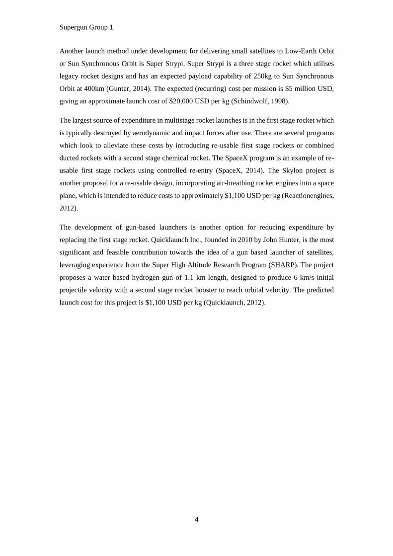
To estimate performance and requirements of the gas gun, [2] has been used to calculate the
required initial pressure of the hydrogen. This equation has been developed for a single stage
light gas gun, therefore the effect of the piston and the gunpowder has not been considered and
the gas is assumed to be a perfect gas with no losses due to friction or heat transfer (Bernier,
2005).
[3]
Where p0 is the initial pressure, a0 is the speed of sound in the gas, v is the muzzle velocity, γ is
the ratio of the specific heats, M is the mass of the projectile, L is the barrel length and S is the
barrel cross sectional area. The mass of the projectile has been assumed to be 150kg and a bore
of the barrel has been assumed to be 0.8m. The required velocity has been assumed to be 6km/s.
The pressure required to reach this velocity has been calculated as a function of barrel length
and gas temperature; the results are plotted in Figure 2. From this data, at a temperature of 900K
and a barrel length of 700m the pressure required is 367MPa. This is an achievable pressure
and is similar to that used by the SHARP gun, which had a hydrogen pressure of 405MPa
(Astronautix, n.d.).
Figure 2: Plot of barrel length against required pressure for a range of temperatures
Supergun Group 1
9
2.1.2. Booster
A booster rocket will be incorporated into the projectile launch system to achieve orbital
velocity at the required altitude, if necessary there will be an additional booster stage to assist
reaching the required altitude. There are several classifications of rockets including ducted,
chemical, nuclear rockets and electrical rockets. For the purpose of this project ducted rockets
have been deemed unfit as their effective altitude limit is approximately 14-20km. Alternative
electric propulsion systems characteristically have low thrust and therefore low acceleration,
which makes them unsuitable for this application. Nuclear rockets are also unfeasible due to
the complications associated with them such as power control, radiation and intense heat.
Technology readiness is also a major factor in the decision hence chemical rockets have been
selected for this project.
2.1.2.1. Chemical Rockets
Chemical propulsion rockets create propulsion from hot gas expansion created by the
combustion of chemical products. There are several types of chemical rocket which may be
considered for this application, these are;
Liquid bipropellant – This propulsion system consists of a liquid fuel and a liquid oxidiser
which are mixed in a combustion chamber, ignited and exhausted through a nozzle to create a
hot gas jet thrust. These can be controlled by using a pressurised gas feed or a pump feed system
depending on the fuel burn rate required.
Liquid monopropellant – A liquid monopropellant system uses a liquid fuel which also
contains an oxidising species. The liquid produces a hot gas when properly catalysed which
produces thrust through a nozzle.
Solid propellant – Solid fuel rockets give a continuous thrust once ignited until the fuel is fully
combusted. These rockets may not be adjusted or re-ignited once extinguished. The combustion
takes place in the same chamber as the fuel storage and therefore the system is very simple and
does not require additional pressurised chambers or valves.
Hybrid – hybrid propellant rockets have a combination of both a liquid and solid propellant.
Typically they consist of a solid fuel grain with a liquid injected oxidiser. Similarly to a solid
propellant rocket the solid fuel combusts in the same chamber in which it is stored. This type
of rocket may be controlled to give variable thrust and also exhibit stop and start capability.
The system requires only one valve to control the injection of liquid oxidiser and two storage
chambers, making it a relatively simple design. Some disadvantages of hybrid rocket propulsion
are variations in specific impulse known as engine chugging (Biblarz, 2010).

Supergun Group 1
10
Table 3 shows a comparison of the aforementioned rocket systems. It is clear from this table
that a hybrid propellant rocket will be the most suitable for this mission, and as of such shall be
adopted in continuation of the project.
Table 3: Comparison of chemical rocket propellant arrangements (Boiron & Cantwell, 2013) (Jubb, 2011)
(Biblarz, 2010).
Type of Rocket Specific
Impulse (sec)
Thrust to Weight
Ratio kN/kg
Technology
Readiness
Chemical – Solid or Liquid
Bipropellants 200-468 10-2 - 100 Flight Proven
Liquid – Monopropellant 194-223 10-1-10-2 Flight Proven
Hybrid Propellant 300-400 10-1 Flight Proven
2.1.3. Structure & Mechanical Design
Based on the analysis of alternatives in Section 2.1 the proposed launch system will use light
gas gun technology with hydrogen as the propellant gas. The following parameters will be
considered during optimisation of the gun design;
Initial temperature, pressure and volume of the light gas.
Mass, diameter and distance travelled of the piston.
Type of gun powder used, its mass and the combustion chamber volume.
Pressure at which the diaphragm ruptures and the projectile is realeased.
Barrel vaccuum system.
Design of the projectile.
Barrel thickness.
2.1.3.1. Gun Support Structure
One option for the support of the gun barrel is to install it within the ground at the launch
location. The main advantage of this is it provides uniform support along the length of the gun
barrel in addition to thermal shielding; this limits the thermal gradient of the structure. There
are associated disadvantages to this option such as construction challenges and inability to
adjust the inclination and orientation of the barrel; this may limit launches to a small range of
orbital altitudes.
Another option for barrel support is the use of mechanical structures such as trunnions, truss
supports or hydraulic cylinders. These options facilitate rotation and launch attitude adjustment
however considerations will be necessary for thermal shielding of the barrel. The barrel can be
made from a light material or made thinner incrementally along its length.

Supergun Group 1
11
To mitigate strains from launches an effective recoil system, a sufficiently strong structure, and
an incredibly straight projectile acceleration path are required.
2.1.3.2. Barrel Thermal Shielding
To reduce thermal strain on the barrel a cooling system will be implemented using thermal
shielding. This can be achieved by painting the barrel with silicate white paint or covering the
barrel with Aluminised or Silver coated FEP mitigating the power usage associated with a heat
exchange system (Savage, 2011).
2.1.3.3. Attitude Control
Optimal launch attitude has been calculated at 20-30° from the normal to the Earth’s surface
(vertical). For a varying attitude gun the support system will include attitude control, a sketch
of this proposed design may be found in Appendix B.
2.2. Projectile
The objective of the projectile is to safely deliver the useful payload to orbit. The constraints
within which the useful payload will conform are: it must have a mass less than 20kg, and fit
within a 30cm in diameter cylinder of length 30cm. It must also be able to sustain acceleration
forces of 1000g (P.Cox, 2014).
2.2.1. Aerodynamic Effects
Upon leaving the gun barrel, the projectile is expected to be travelling at hypersonic velocities
and therefore key aerodynamic characteristics must be considered. The projectile will create
shock waves on or before the leading edge and thick, viscous, turbulent boundary shock layers.
Furthermore, temperature rises significantly across the shock wave. This makes projectile
design key to maintaining aerodynamic efficiency and ensuring projectile survivability.
For a sharp body the shockwaves formed will be attached oblique shock waves, either
compressing or expanding the flow depending on the direction of the angle the hypersonic flow
is required to turn through. The flow behind an attached oblique shock wave typically remains
supersonic. When the deflection angle is greater than that of the maximum achievable by the
hypersonic flow, a detached shock wave will form in front of the body, which is known as a
bow shock, see Figure 3. Behind a detached oblique shock wave there is a region of subsonic
flow, before a transition returning to supersonic flow.

Supergun Group 1
12
Figure 3: Left, oblique shock wave attached to the nose of a sharp body. Right, bow shock wave detached
from the surface of a bluff body (Hartman, 1968).
The contribution to drag due to a shock wave is called wave drag, this can be calculated from
the deflection angle of the flow and the pressure drop across the flow (Grabow, 1965).
In addition to this there will be another component of drag called the parasitic drag. This is
comprised of skin friction and pressure drag. The skin friction is related to Reynolds number in
turbulent flows by the 1/7th power law. This component of drag will therefore scale with the
characteristic length of the projectile. Pressure drag is related by the pressure coefficient of the
projectile, which is determined by boundary layer reattachment due to projectile shape.
At sufficiently high Mach number the lift, pressure and drag coefficients of an object behind a
shock wave become Mach number independent (Anderson J. D., 2001). An estimated drag
coefficient for the projectile has been chosen as 0.6 based on a cone with wedge angle of 60°
(Anderson J. D., 2001).
The design of the projectile will be a trade-off between the optimal aerodynamic profile and a
geometry which limits the thermal energy absorbed by the projectile, to ensure payload
survivability.
Figure 4: Conceptual CAD design of the supergun projectile

Supergun Group 1
13
Figure 4 is an initial design for the projectile. It depicts a pointed nose with a slender body and
a rear ‘boat tail’ design, with fins for stability. Shown in white is a component for thermal
shielding, in green are the electronics, control systems and avionics, in red is the useful payload
bay, in bronze is the liquid oxidiser pressure vessel of the hybrid rocket, in blue is the solid fuel
and combustion chamber vessel, and in black is the rocket nozzle.
Once an initial design has been created it is possible to use computational fluid dynamics to
compare analytical solutions for the coefficient of drag. Computational results may also be used
to predict the temperature on the surface of the projectile.
2.2.2. Thermal Effects
Across an oblique shockwave, there is an almost instantaneous rise in temperature, resulting in
the conduction of extreme heat to the skin of the projectile. From isentropic flow relationships,
it can be shown that the temperature downstream of a shock wave at Mach 10 is more than 10
times greater than the upstream temperature. Another aspect to consider is the temperature
caused by the stagnation point on the nose of the projectile. The process of losing the air flow’s
kinetic energy results in calculable localised high temperatures. Furthermore, thermal
conduction on the skin of the projectile can be significant (Allen, 1958).
When in orbit, one side of the projectile will be subject to solar radiation this will create large
temperature gradients which must also be taken into account.
A thermal shield on the nose of the projectile will be required to reflect and dissipate heat away
from the internals of the projectile. There are a range of methods for thermal shielding, three of
these methods are;
Thermal barrier coatings such as yttria-stabilized zirconia.
Thermal radiation reflection using elements such as gold and silver.
Ablative thermal shields such as AVCOAT.
Insulation will also be applied to any exposed structural architecture to ensure no significant
thermal gradients will affect the integrity of the core structure. The selection and fixing of such
insulation will be driven by the operational performance of each option and the availability and
cost.
Supergun Group 1
14
2.2.3. Orientation and Stability
The orientation and spin of the projectile must be stable after launch to enable a predictable
altitude and trajectory. Once the projectile is launched, stability and orientation will be obtained
passively through the aerodynamic design and stability mechanisms. When in orbit, active
orientation control systems will be required to make translational as well as rotational
adjustments.
The two main concepts for ensuring this while maintaining low drag are;
Gyroscopic stability obtained through rotating the projectile about its primary axis.
Centre of pressure position.
Gyroscopic stability is common place in the design of artillery shells. Most cannons will have
a rifled barrel to impart a spin on the projectile. Once spinning the angular momentum of the
projectile means that any perturbations will create gyroscopic procession. This phenomenon is
typically not an issue for artillery shells due to their limited time in the air before hitting a target.
This act of procession will increase the drag acting on the projectile.
Moving the centre of aerodynamic pressure behind the centre of mass will increase
aerodynamic stability. To move the centre of aerodynamic pressure, drag must be increased
towards the rear of the projectile. This can be achieved through the application of fins to the
rear; the overall coefficient of drag will also increase. The in-flight integrity of the fins will be
critical to the survivability of the entire projectile, thus must be designed to withstand the
aerodynamic pressures associated with hypersonic flight.
2.2.4. Structural Architecture
Similar to conventional launch vehicles, the projectile will be required to withstand large
vertical loads due to the extreme acceleration; however these will more likely be in order of
1000g compared to a conventional rocket launch peak acceleration of 24g (P.Cox, 2014). Along
with the high acceleration, the resulting extreme aerodynamic pressure acting on the projectile
will require the structure to withstand high hoop stresses. Therefore the projectile’s core
structure is required to be strong as well as light, to facilitate a survivable and efficient launch.
Furthermore, at launch, the rear face of the projectile will be required to absorb the shockwave
and pressure created by the expanding gas behind it, allowing the projectile to reach hypersonic
velocities. External factors such as untracked micrometeorites will require the structure to resist
penetration from high velocity, low mass projectiles.
Supergun Group 1
15
Along with securely containing all components of the projectile, the structure will also have to
break apart and separate from the useful payload to release the useful payload into orbit. After
the release of the useful payload, the launch projectile must complete a controlled de-orbit
process through the atmosphere to ensure that no unnecessary debris is left in orbit after the
mission.
Typical rocket launch vehicles use an aluminium lithium alloy such as AL-Li 2195 which is a
high strength light alloy. Structural strength can be achieved using a truss architecture,
minimising the material and therefore mass required. A range of materials will be suitable for
designing the structure of the projectile including Al 6062, Ti 6-4 or composite materials such
as carbon or Kevlar fibre reinforced metals or graphene reinforced carbon.
2.2.5. In-Barrel
To ensure the maximum achievable efficiency at launch using a first stage supergun, the
projectile fired must be machined to a close tolerance of the bore of the barrel. To enable the
projectile to also be of a geometry optimised for aerodynamic effects, a sabot is used to ensure
close tolerances between the barrel and the projectile. Additionally the sabot acts as a barrier
between the gun barrel and the surface of the projectile to ensure the integrity of the projectile
upon leaving the barrel. Through the use of a weak, sacrificial surface it can also limit the wear
experienced by the bore of the barrel. Design of the sabot will be closely linked to the geometry
of the projectile to ensure an even load distribution across the projectile. The sabot will also be
designed to be aerodynamically unstable to ensure that it will quickly tumble away from the
projectile after launch.
2.3. Projectile On-board Electronics
2.3.1. Projectile Electronic System Overview
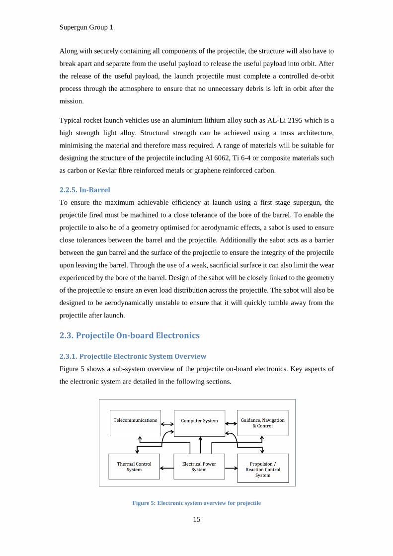
Figure 5 shows a sub-system overview of the projectile on-board electronics. Key aspects of
the electronic system are detailed in the following sections.
Figure 5: Electronic system overview for projectile
Supergun Group 1
16
2.3.2. Guidance, Navigation & Control (GNC)
The information from sensors in the GNC, supply the control systems with feedback
measurements. Additionally, the data can support the ground control station operation to
monitor the progress of the projectile following launch. This section describes the common
sensors used on spacecraft.
2.3.2.1. Attitude sensors
Attitude sensors are used to generate reliable data to describe the physical orientation and
position of the projectile. It is very common for the projectile to have a desired path to follow
designated prior to launch. The sensor data is used in an internal feedback control system to
maintain this path as well as being transmitted to the earth station.
There are two types of attitude sensors typically used for launch projectiles: relative attitude
sensors and absolute attitude sensors. These sensors vary in size, weight and sensing
mechanism.
A gyroscope is one of the most common relative sensors, which senses rotation in three
dimensions (roll, pitch and yaw). Traditional gyroscopes rely on a spinning moment of inertia,
which does not change orientation with the surrounded force acting on it. This is then referenced
to detect the orientation of the projectile.
2.3.2.2. Pressure sensors
Pressure sensors are devices that detect the pressure of gases or liquids. They can be used to
measure the fuel tank pressure and also the internal pressure of the projectile. Pressure sensors
can also support the control system to optimise the combustion of hybrid fuel.
2.3.2.3. Servo type accelerometers
Servo type accelerometers detect the acceleration of an object in three dimensions of
translational movement. Traditional accelerometers used piezoelectric or capacitance
technology to measure acceleration. These traditional mechanisms lead to a small mass
displacement that reduces the accuracy of the accelerometer. In comparison, the servo type
accelerometer is a closed loop device, which keeps internal deflection of the proof mass to a
minimum, hence providing a better accuracy for measurement of acceleration (Wilson, 2004).
2.3.3. Telecommunications System
A communication system is needed for the projectile in order to communicate with ground
control. The system is expected to receive instructions from the earth station and also send
essential information such as physical condition and orientation of the projectile to the ground.
This section describes the communication subsystem used and also the antenna of the projectile.

Supergun Group 1
17
2.3.3.1. Telemetry, tracking, and command subsystem (TT&C)
The Telemetry, Tracking, and Command subsystem (TT&C) is responsible for data
communications enabling the monitoring and controlling of the projectile from take-off to an
orbit location (Pattan, 1993). Early satellites used very high frequency (VHF) and Super high
frequency (SHF) for TT&C data transmission due to lower power consumption (Pattan,
1993). Figure 6 shows a schematic of the proposed telemetry, tracking & command system.
Figure 6: Schematic of telemetry, tracking, and command (TT&C) system.
The telemetry system collects all the data from the sensors of the projectile including
temperature, pressure in the fuel tank and attitude. The data is usually digitalized and coded
with Frequency Shift Keying or Phase Shift Keying before transmission via an omnidirectional
antenna (Mitra, 2005). Uplink and downlink frequency are usually different to prevent
unwanted interference.
The tracking system is used to determine the orbit of the projectile by calculation from
previously detected positions, using accelerometer and velocity sensor data. This data provides
an estimated range of movement for the projectile. The location of the projectile can then be
cross-checked and corrected by triangulation of multiple earth stations with time delay and earth
elevation angle, similar to a GPS system (Mitra, 2005).
The command system is a system for controlling the projectile to perform specific actions after
processing the received data. For example the system can be used to manually adjust attitude
to protect the projectile from entering other satellite orbits due to unexpected disturbances. To
prevent unauthorized TT&C command, the data transmitted is normally encrypted.
2.3.3.2. Antennas
An antenna is an electrical device that is used as a transmission medium for radio waves. In
satellite communication, they are mainly classified into two types of antennas, earth station
antennas and satellite antennas (Roddy, 1989).

Supergun Group 1
18
In designing the antenna it is important that the gain should be balanced with power
consumption to produce a sensible Equivalent Isotropic Radiated Power (EIRP).
2.3.4. Propulsion / Reaction Control System
A control system is to be devised which incorporates the activation of the secondary booster
stage to achieve altitude and velocity requirements for orbital insertion combined with
peripheral thrusters for the purpose of attitude control. It is known that by taking measurements
from the sensors used for guidance and navigation, an algorithm performing Proportional
Integral Differential (PID) control can be used to ensure that the correct trajectory is followed.
2.3.5. High/Low Temperature Electronics Survivability
It is understood that the supergun launch strategy would lead to considerable temperature
extremities due to (P.Cox, 2014), (NASA, NASA, 2014):
Compression of Hydrogen.
Barrel friction.
Shock waves.
Skin friction.
Solar Radiation.
These conditions are problematic due to the operating temperatures of electronics being limited,
typically -55°C to 125°C for military grade electronics integrated circuits and components, and
approximately -30°C to 60°C for batteries (Xilinx, 2014), (Administration, 2014).
To protect the electronics from malfunction and damage, it is necessary to implement a Thermal
Control System (TCS) which can regulate the electronics systems through passive and active
means such as Multi Layer Insulation blankets and radiators, based on temperature sensor
information. The design of thermal control systems such as would be required for this project
is well established, due to developments in electronics for atmospheric entry whereby
temperatures of 1650°C or greater can be observed (Aerospace, 2014).
2.3.6. High g Launch Electronics Survivability
One key difference between a rocket launch and gun based launch is that whereas a rocket
launch typically operates accelerations of around 4g, a gun launch can be in the order of
thousands of g (Page, 1988) (P.Cox, 2014). This is due to the rapid acceleration in the gun
launch method used to achieve the high velocity required to attempt orbital insertion.

Supergun Group 1
19
A key design choice in regards to the gun design to reduce the peak g force loading is using a
gun with large calibre and using a discarding sabot. Internally, within the projectile, despite g
force loading being reduced by gun design choices, there will still be a very large g force
loading.
Loading that may impact on internal circuitry can be from a number of sources, including (L3
Communications Interstate Electronics, 1999):
Setback shock from axial acceleration.
Setforward shock at gun barrel exit.
In barrel lateral shock due to imperfections in the barrel.
Centrifugal force from rifling or spinning of the projectile.
Figure 7: Gun shock acceleration vs. time profile a) theoretical b) real (Colibrys, 2012)
To accurately characterise the potentially damaging mechanical properties of the launch
method, it is desirable to analyse the short duration shock pulse in time and frequency as shown
in Figure 7. It can be seen that the real acceleration characteristic has two distinct regimes: long
high magnitude shock as in the ideal case and high frequency shocks due to imperfections in
the gun design (Colibrys, 2012). Such test curves are useful as they allow the projectile designer
to determine potential mechanical resonance damage, and to design for the high axial
acceleration loading.
Failure modes of electronic circuitry can be characterised in the following categories (L3
Communications Interstate Electronics, 1999):
Short and open circuit tracks.
Detached of parts.
Cracks in parts or epoxy.
Change in value for resistors, capacitors, inductors, crystal oscillators.

Supergun Group 1
20
The electronic systems of the projectile can be ruggedised in numerous ways including (L3
Communications Interstate Electronics, 1999):
Use of low height surface mount resistors, capacitors, inductors.
Use of Stress-Compensated (SC) crystals.
Use of Ball Grid Array (BGA) integrated circuit packages.
Smaller, thicker and well supported PCBs with metal stiffener supports.
Adhesive and epoxy encapsulation of components.
2.4. Trajectory Simulation
Trajectory optimisation is necessary to ensure economical and environmentally sustainable
launch. The initial estimates for horizontal and vertical delta v were determined for a fully
vertical gun. Table 4 shows the results for a variety of altitudes.
Table 4: Velocity required to achieve a range of orbits
Orbit Type Altitude (km) Theoretical velocity
required (m/s)
Theoretical orbital
velocity (m/s)
Escape Infinity 11200 N/A
LEO 160 1750 7810
LEO 1000 4120 7350
LEO 2000 5460 6900
MEO 10000 8740 4930
GEO 35800 10300 3070
The next stage was to include a drag model; this was done using Newtonian theory with a
density/altitude gradient according to the MSIS-E-90 model and a gradient for the universal
gravitational constant to give the change in the projectile’s acceleration (NASA, n.d.). This was
then used to estimate the trajectory of the projectile’s flight as a three dimensional model
accounting for the Earth’s rotation.
A key method to improve the efficiency of launch is to minimise the drag of the projectile. For
this reason the launch location will be at an altitude greater than 2km. Figure 8 shows the results
given from MATLAB. A list of the estimated parameters may be found in Appendix C. A code
for optimisation of these initial parameters is currently being developed. A pseudo code for this
can be seen in Appendix A.

Supergun Group 1
21
Figure 8: Altitude versus time plots comparing an initial altitude of 0 km (left) with one of 2000 km (right).
2.5. Location & Structures
2.5.1. Considerations
In order to determine a suitable launch site for this project it is necessary to consider a number
of variables, such as polar or equatorial launch site, direction of firing, elevation and
infrastructure. It was also necessary to consider what type of payload would be launched and
the type of orbit required.
An easterly launch direction has been chosen in order to take advantage of the earth’s West to
East spin to provide greater angular speed to the projectile as it is launched. In order to take
greatest advantage of this affect, a location close to the equator would be considered favourable
as the surface of the earth is spinning faster at the equator than at the poles. An equatorial launch
has been chosen as opposed to a polar launch. Due to the risk of fallout during launch and the
risk of mission failure leading to the projectile returning to earth, the site should be located on
an eastern coast with a large body of water to the east, in order to allow for easterly firing
without the risk of injury or damage to property.
Locating the launch site above sea level would be beneficial as air density decreases with
altitude, as shown in Table 5, and therefore the drag experienced by the projectile would be
reduced. Locating the launch site at altitude will present many challenges including transporting
building materials, construction and possible adverse weather conditions. A minimum altitude
of 2000m has been chosen to be a suitable compromise.

Supergun Group 1
22
Table 5: International standard atmosphere data (Mayhew, 1994).
Altitude (m) ρ/ρ0 ρ
0 1 1.23
500 0.953 1.17
1000 0.908 1.11
1500 0.864 1.06
2000 0.822 1.01
2500 0.781 0.957
3000 0.742 0.909
3500 0.705 0.863
4000 0.669 0.819
4500 0.634 0.777
5000 0.601 0.737
In order to minimise the risk to human life in the event of mission fall out the launch site must
be located a safe distance from populated areas.
The launch site will need to have a sufficient area to house the relevant ground works including
the firing mechanism, recoil absorption system, control centre, fuel storage and staff facilities.
It must also be suitably accessible to support all necessary groundwork, including the
construction of roads and tunnels.
The firing of the gun will cause a significant amount of recoil and so the launch site geology
must be suitable to support a recoil system without causing significant damage to the
surrounding area.
The surface geology at the launch site must be capable of supporting major building work and
be able to withstand the forces associated with recoil from the gun.
The location must not be subject to weather conditions severe enough to greatly limit the
frequency of firing.
2.5.2. Requirements
Coastal site with a large body of water located to the east.
Within 20° latitude from the equator.
Minimum altitude of 2000m above sea level.
Minimum of 10 miles from highly populated areas, with no highly populated areas
located to the east.
Suitable geology and access to support building work.
Must not be subject to severe weather conditions which could severely limit the
frequency of firing.
Supergun Group 1
23
2.5.3. Locations Considered
In order to find suitable launch sites the following process was used to assess the suitability of
a number of options:
List countries with an eastern cost to a large body of water that are within 20° latitude
of the equator.
Find maximum altitude of each country to filter those without high points above
2000m.
Check if there are high points near the coast.
Check the locations proximity to populated areas.
Check location geography and geology.
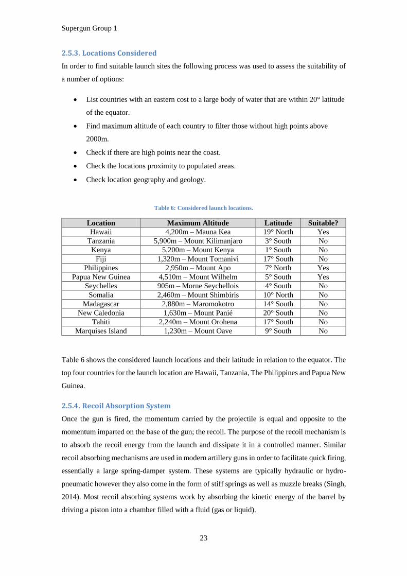
Table 6: Considered launch locations.
Location Maximum Altitude Latitude Suitable?
Hawaii 4,200m – Mauna Kea 19° North Yes
Tanzania 5,900m – Mount Kilimanjaro 3° South No
Kenya 5,200m – Mount Kenya 1° South No
Fiji 1,320m – Mount Tomanivi 17° South No
Philippines 2,950m – Mount Apo 7° North Yes
Papua New Guinea 4,510m – Mount Wilhelm 5° South Yes
Seychelles 905m – Morne Seychellois 4° South No
Somalia 2,460m – Mount Shimbiris 10° North No
Madagascar 2,880m – Maromokotro 14° South No
New Caledonia 1,630m – Mount Panié 20° South No
Tahiti 2,240m – Mount Orohena 17° South No
Marquises Island 1,230m – Mount Oave 9° South No
Table 6 shows the considered launch locations and their latitude in relation to the equator. The
top four countries for the launch location are Hawaii, Tanzania, The Philippines and Papua New
Guinea.
2.5.4. Recoil Absorption System
Once the gun is fired, the momentum carried by the projectile is equal and opposite to the
momentum imparted on the base of the gun; the recoil. The purpose of the recoil mechanism is
to absorb the recoil energy from the launch and dissipate it in a controlled manner. Similar
recoil absorbing mechanisms are used in modern artillery guns in order to facilitate quick firing,
essentially a large spring-damper system. These systems are typically hydraulic or hydro-
pneumatic however they also come in the form of stiff springs as well as muzzle breaks (Singh,
2014). Most recoil absorbing systems work by absorbing the kinetic energy of the barrel by
driving a piston into a chamber filled with a fluid (gas or liquid).

Supergun Group 1
24
The compressed fluid is then stored within a pressure vessel and then the energy is released in
a controlled manner such as through a valve to drive a piston or through a turbine to power a
drive shaft.
A recoil absorbing mechanism on a supergun is necessary to limit the effect a launch will have
on the mountings and foundations of the supergun and therefore also limit the effect on the
surrounding environment. To enable a fluid to absorb the energy from launch, the base of the
gun behind the projectile must be able to move, with respect to the piston, which will require
careful design considerations to successfully integrate it with the gun barrel and combustion
chamber. Therefore the recoil absorbing mechanism is assumed to be a structurally significant
part of the gun design.
2.5.5. Launch Site & Ground Work Considerations
Since a gun of this size has not yet been used for satellite launch applications it is not known
what effect firing will have on the ground beneath the launch site and whether or not this could
cause earthquakes or other seismic activity. Also, it would be difficult to predict the landing
site of debris in the event of a mission failure or catastrophic gun failure without the use of
sophisticated computer modelling.
Furthermore, the immediate and long term impact on the environment is not known and it is
not known if planning permission will be granted for the chosen launch site.

Supergun Group 1
25
3. Project Risk Management
Risk Risk Description Severity Probability
Risk
Severity
Index
Risk Mitigation
Mission Risks – Terrestrial
Projectile, booster
and/or sabot
fallout
Risk of all or parts of the
projectile, booster or sabot
landing in populated area
5 2 10
Launch direction will be due east. Launch site is on an east
coast with no populated areas within 600 km due east. There
are no densely populated areas within a 50 km radius.
Projectile collision
with air traffic
Risk of collision between the
projectile, sabot or fallout, and
private, commercial or military
air traffic.
5 1 5
The local aviation authority would have to grant permission
before launch and air traffic control would be notified. A
NOTAM (notice to airmen) would be published prior to
launch.
Uncontrolled
explosion at
launch
Risk of explosion of propulsion
products on, before or after
launch in an uncontrolled
manner.
4 2 8
Flammable material must be stored the recommended safe
manor. During launch no one will be located within 5 km of
the launch site
Uncontrolled
destruction of the
projectile after
launch
Risk of inflight destruction of the
projectile and the useful payload
at launch.
5 2 10
The projectile will be designed with a suitable safety factor to
compensate for the expected aerodynamic pressures and
resonating frequencies at launch.
Uneven expansion
or deflection of
the gun barrel
Risk of the barrel deforming due
to temperature, wear or structural
effects, resulting in a failed
launch.
2 3 6
The gun barrel will be designed with insulation to mitigate the
effects of uneven temperature. A suitable support structure
will be designed to ensure the structural strength and accuracy
of the barrel
Interruption of
Communications
Risk of loss or interruption of
communications during launch
due to plasma and ionising gas
effects.
2 5 10
Antennas will be shielded from ionising gases to allow
communications. The projectile will be capable of automated
flight and trajectory control

Supergun Group 1
26
Adverse Tectonic
Activity
Tectonic activity in the local area
with the potential of disrupting a
launch.
4 4 16
The launch site facilities and foundations will be designed
using a suitable safety factor, to survive an earthquake of
typical regional magnitude.
Mission Risk – In Orbit
Collision with
debris or other
satellites in orbit
Risk of a collision between the
projectile or useful payload, and
in orbit satellites or debris
5 2 10
The trajectory of launch will be set before launch to avoid in
orbit bodies. Any significant deviation from this predicted
course will result in a mission abort.
Solar Radiation
Risk of disruptions to the mission
from solar radiation, solar flares
and coronal mass ejections
3 4 12
The activity of the sun at launch will be checked to ensure a
low solar activity. The projectile will include basic shielding
to prevent significant disruption from solar radiation
Orbital Decay
Risk of losing altitude in orbit
due to small but not insignificant
aerodynamic drag forces.
1 5 5 The decay of an orbit due to drag can be predicted therefore
necessary thrust input can be scheduled during the mission.
Project Risks
Launch Schedule
risks
Risk of causing disruption or
cancelation of a launch due to
project/construction delay
4 3 12 Agreed project management process and use of a Gantt chart
will be used to assure on time delivery of launch
Financial Risk
Risk of the cost of construction
and launch being greater than
predicted resulting in financial
loss
4 3 12 Agreed project management process and constant assessment
of cost will be used to assure on budget delivery of launch
Human Risk
General risks caused by poor
workforce methods during
construction and launch
5 3 15
A strict adherence to local/accepted health and safety laws to
ensure a safe construction and launch process. Project specific
methods for human work and the use of machines will
minimize human errors.
Construction
Risks
Risk of delivery and construction
of a not to specification launch
system
4 2 8
During manufacturing and construction of the gun, set
tolerances of parts will be followed and measured to assure a
within specification launch system.

Supergun Group 1
27
4. Project Organisation & Management
The project is broken down in to smaller sections according to the strength of group members
which come from different engineering disciplines. Table 7 shows the responsibility of group
members.
Table 7: Group member allocations
Group member Responsibilities
Aidan Cookson Projectile design.
Jack Feakins Control system and actuators.
Kin Man Benjamin Lee Sensors and communication system.
Sophie McElhill Launch systems design.
Alex Oses Trajectory simulation, MATLAB analysis.
Eleri Williams Launch location analysis, launch site design and access.
Formal and informal meetings are held regularly to update the project progress with formal
meetings taking place every Tuesday with three academics. A meeting agenda is provided
before the formal meeting and minutes are produced within 48 hours after the meeting.
Individual and group weekly goals are setup and reviewed after the formal meeting in order to
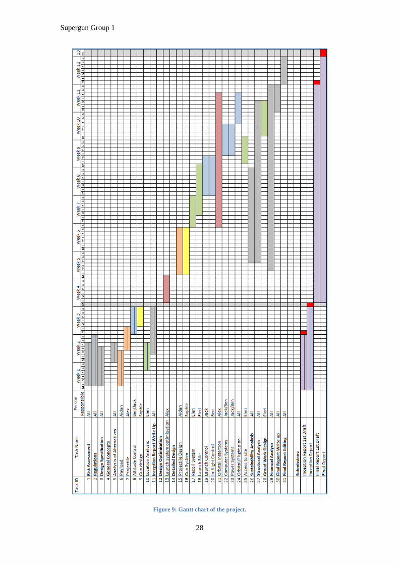
keep the project on track. Current Gantt chart with the latest progress is shown in Figure 9.
Supergun Group 1
28
Figure 9: Gantt chart of the project.
Supergun Group 1
29
5. Bibliography
Administration, P. O. (2014). Pennsylvania Office of Administration. Retrieved October 22,
2014, from http://oa.state.pa.us/portal/server.pt/document/1219030/ecr-
5892d_nicd_nimh_li-ion_pdf_(2)
Aerospace, T. V. (2014). Terminal Velocity Aerospace. Retrieved October 22, 2014, from
http://www.tvaero.com/reentry.shtml
Allen, J. E. (1958). A Study of the Motion and Aerodynamic Heating of Ballistic Missiles
Entering the Earth's Atmosphere at High Supersonic Speeds. NACA Report 1381.
Anderson, J. D. (2001). Fundementals of Aerodynamics (3rd ed.). New York, NY: McGraw
Hill.
Anderson, J. D. (2006). Hypersonic and high temperature gas dynamics (2nd ed.). Reston,
Va: American Institute of Aeronautics and Astronautics.
Astronautix. (n.d.). Retrieved 2014, from http://www.astronautix.com/articles/abroject.htm
Astronautix. (n.d.). Super High Altitude Research Project. (astronautix.com) Retrieved
October 2014, from http://www.astronautix.com/lvs/sharp.htm
Bernier, H. (2005). Scaling and Designing Large-Bore Two-Stage High Velocity Guns. In D.
L. Dr. Lalit C. Chhabildas, High-Pressure Shock Compression of Solids VIII; (pp. 37-
84). New York: Springer.
Biblarz, O. &. (2010). Rocket Propulsion Elements (8th ed.). Hoboken, NJ: Wiley & Sons,
Inc.
Boiron, A. J., & Cantwell, B. J. (2013). Hybrid Rocket Propulsion and In-Situ Propellant.
American Institute of Aeronautics and Astronautics, 6.
Colibrys. (2012). Colibrys. Retrieved October 22, 2014, from
http://www.colibrys.com/files/pdf/products/30N.GunH.C.04.12.pdf
Emerick, R. e. (2014, March/April). The Sky's The Limit. IEEE Microwave Magazine, pp.
65-78.
Evans, B. (1999). Satellite Communication Systems, 3rd Edition (3rd ed.). Guildford:
Institution of Engineering and Technology.
Grabow, R. e. (1965). The Determination For Hypersonic Drag Coefficients For Cones And
Spheres. Wilmington, MA: AVCO Corporation.
Gunter, D. (2014). Gunter's Space Page. Retrieved October 22, 2014, from
http://space.skyrocket.de/doc_lau/super-strypi.htm
Hartman, E. P. (1968). Adventures in Research: A History of Ames Research Center 1940-
1965, Part II. NASA.
IEEE. (1984). IEEE Standard Letter Designations for Radar-Frequency Band (1st ed.). New
York: IEEE Aerospace and Electronic Systems Society .
Jubb, D. (2011). DEVELOPMENT AND TESTING OF THE BLOODHOUND SSC
HYBRID ROCKET. THE BLOODHOUND PROJECT. Retrieved 10 25, 2014, from
http://www.bloodhoundssc.com/project/car/engines/rocket-engine/rocket-
development
Supergun Group 1
30
Kaye, R. e. (1995). Design and evaluation of coils for a 50 mm diameter induction coilgun
launcher. Magnetics, IEEE Transactions, 31(1), 478-483.
L3 Communications Interstate Electronics. (1999). L3 Communications Interstate Electronics
Corp. Retrieved October 22, 2014, from http://caxapa.ru/thumbs/262855/High-
G_Ruggedization_Methods.pdf
Ley, W. W. (2009). Handbook of Space Technology (1st ed.). New York: John Wiley & Sons.
Mayhew, Y. R. (1994). Thermodynamic and Transport Properties of Fluids SI Units (7th ed.).
Oxford, UK: Blackwell.
McNab, I. R. (2013). Electromagnetic Augmentation Can Reduce Space Launch Costs. IEEE
Transactions On Plasma Science, 41(05), 1047-1054.
McNab, I. R. (2014). Pulsed power options for large EM launchers. Electromagnetic Launch
Technology (EML), 2014 17th International Symposium on. Retrieved Nov 2014,
from http://ieeexplore.ieee.org/stamp/stamp.jsp?tp=&arnumber=6920691
Mitra, M. (2005). Satellite Communication (1st ed.). New Dehli: PHI Learning Pvt. Ltd.
Museum, B. (2012). Retrieved from http://www.barbmuse.org.bb/2012/01/harp-gun-hike/
NASA. (2007). Retrieved from http://history.nasa.gov/sputnik/
NASA. (2014). NASA. Retrieved October 22, 2014, from http://www.grc.nasa.gov/WWW/k-
12/airplane/isentrop.html
NASA. (n.d.). MSIS-E-90 Atmosphere Model. Retrieved October 26, 2014, from
http://omniweb.gsfc.nasa.gov/vitmo/msis_vitmo.html
NASA. (n.d.). White Sands Test Facility, Laboratories, Hypervelocity, Two-Stage Light Gas
Guns. Retrieved October 2014, from nasa.gov:
http://www.nasa.gov/centers/wstf/laboratories/hypervelocity/gasguns.html
Northern Sky Research. (2012). Global Satellite Manufacturing & Launch Markets.
P.Cox. (2014). Daily Reckoning 2011. Retrieved October 22, 2014, from
http://dailyreckoning.com/space-guns
Page, T. A. (1988). The Apollo Saturn Reference Page. Retrieved October 22, 2014, from
http://www.apollosaturn.com/s5flight/sec2.htm
Pattan, B. (1993). Satellite systems: principles and technologies (1st ed.). Dordrecht: Kluwer
Academic Publishers.
Quicklaunch. (2012). Quicklaunch. Retrieved October 22, 2014, from
http://web.archive.org/web/20120724005949/http:/quicklaunchinc.com/
Reactionengines. (2012). Reactionengines. Retrieved October 22, 2014, from
http://www.reactionengines.co.uk/about.html
Roddy, D. (1989). McGraw-Hill telecom engineering (1st ed.). New York: McGraw-Hill
telecom engineering.
Schindwolf, E. (1998). Launch of "Smallsats" Using Low-Cost Sounding Rocket,. New
Mexico: 12th AIAA/USU Conference on Small Satellites.

Supergun Group 1
31
Singh, H. &. (2014). Optimal Control of Gun Recoil In Direct Fire Using Magnetorheological
Absorbers. Smart Materials & Structures, 23(5).
SpaceWorks. (2013). Global Launch Vehicle Market Assessment.
SpaceWorks. (2014). Nano/Microsatellite Market Assessment.
SpaceX. (2014). REUSABILITY: THE KEY TO MAKING HUMAN LIFE MULTI-
PLANETARY. Retrieved October 26, 2014, from
http://www.spacex.com/news/2013/03/31/reusability-key-making-human-life-multi-
planetary
The Tauri Group. (2013). State of the Satellite Industry Report.
Wilson, J. (2004). Sensor Technology Handbook (1st ed.). Lynton: Newnes.
Xilinx. (2014). Xilinx. Retrieved October 22, 2014, from
http://www.xilinx.com/support/documentation/data_sheets/ds183_Virtex_7_Data_Sh
eet.pdf
Appendices
Appendix A
Declare constants.
Initialise variables
Run first loop from simulation start time to end time
Get max(Altitude)
For max(Altitude) > (1+X)*RequiredAltitude && max(Altitude) > (1-X)*RequiredAltitude
If max(Altitude) > (1+X)*RequiredAltitude
Initialise variables again
Reduce muzzle velocity by Y%
Run loop
Get max(Altitude)
end
If max(Altitude) < (1+X)*RequiredAltitude
Initialise variables again
Increase muzzle velocity by Y%
Run loop
Get max(Altitude)
end
end
Get muzzle velocity
Get total expended energy and cost
Calculate discrepancy between maximum altitude and the required maximum altitude

Supergun Group 1
32
Appendix B
Appendix C
Estimates used for MATLAB model
Variable Estimated Value
Frontal Cross-sectional Area, S 0.05 m2
Coefficient of Drag, CD 0.6
Gun Length 300 m
Total Mass 150 kg
Barrel Attitude from Vertical 0®
Muzzle Velocity 8340 m/s