SuperGrip SG II - Hultdinshultdins.se/wp-content/uploads/7000300_En0115_sg2-1.pdf · Gland ... Fig....
20
User’s manual SuperGrip SG II
Transcript of SuperGrip SG II - Hultdinshultdins.se/wp-content/uploads/7000300_En0115_sg2-1.pdf · Gland ... Fig....

User’s manual
SuperGrip SG II
2015– HULTDIN SYSTEM AB.
This publication applies to the following models:
SG II 260/-R/-S/-A S/N 048-0858 and up
SG II 300/-R/-S/-A S/N 049-0562 and up
SG II 360/-R/-S/-A S/N 050-0761 and up
SG II 420/-R/-S/-A S/N 051-0714 and up
SG II 520 S/N 055-0004 and up
This publication contains instructions for the installation and handling of the SuperGrip SG II grapples. The instructions cover both general information for all models, and procedures or specifications applicable to individual models. If doubt should arise concerning the validity of the instructions please consult the nearest dealer for more detailed information.
Illustrations, technical information and specifications were, as far as we have been able to judge, correct at the time of print. However, we reserve the right to, without prior notice, revise specifications, instructions, equipment, etc. as a result of ongoing product improvement activities.
No part of this publication may without approval of HULTDIN SYSTEM AB be translated, reproduced, stored or transmitted electronically, mechanically, photographically or in another way not specified here.
Even if all conceivable measures have been taken to make the contents as complete as possible, HULTDIN SYSTEM AB takes no responsibility for possible damages that may arise as a result of the instructions not being followed or improper use of the product.
Important!The parts and components used in HULTDIN SYSTEM AB’s products are specifically chosen. Therefore original spare parts are always the best alternative in a possible need of repairs or upgrading.
All service and repairs should be carried out by qualified service personnel or an authorized repair shop with suitable tools and lifting devices.
This publication is published by: HULTDIN SYSTEM ABSkolgatan 12SE-930 70 MalåSWEDEN
En_sg2TOC.fm contents
CONTENTS
Contents Page Contents Page
Safety instructions.................................................... 5
General safety....................................................... 5
Meaning of safety messages................................. 5
Operational Safety................................................ 6
Maintenance safety............................................... 7
Welding........................................................... 7
Modifying the equipment ............................... 7
Main Parts ................................................................ 8
Product description.................................................. 9
Labeling................................................................ 9
Technical data......................................................... 10
SuperGrip SG II ................................................. 10
Special tools.................................................. 10
SG II ................................................................... 12
SG II R ............................................................... 13
SG II S................................................................ 14
SG II A ............................................................... 15
Functional description ........................................... 16
Installation .............................................................. 17
Installing the rotator ........................................... 17
Maintenance instructions ...................................... 18
Every 10 hours of operation (every day)............ 18
Every 50 hours of operation (every week)......... 19
Lubrication ................................................... 19
The first month of operation .............................. 19
Fasteners ....................................................... 19

CONTENTS
4 contents En_sg2TOC.fm
(This page left empty for possible future additions)
SAFETY INSTRUCTIONS
En011501_sg.fm Safety instructions 5
Safety instructions
General safety
• This page describes important safety instructions, which the operator should have a good knowledge of before the equipment is used.
• This product should only be used by operators with proper knowledge and training.
• The owner and the operator are responsible for following all safety regulations and that the machine is safely equipped.
• The owner and the operator are responsible for following National and local laws, regulations and other instructions when using the product.
• The owner and the operator are responsible for replacing damaged parts and/or unreadable warning signs.
• The manual should be available at all times so that the operator is able to follow safety regulations and the procedures of maintenance activities.
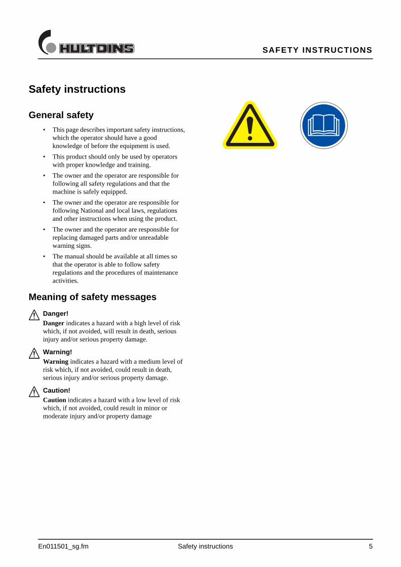
Meaning of safety messages
Danger!
Danger indicates a hazard with a high level of risk which, if not avoided, will result in death, serious injury and/or serious property damage.
Warning!
Warning indicates a hazard with a medium level of risk which, if not avoided, could result in death, serious injury and/or serious property damage.
Caution!
Caution indicates a hazard with a low level of risk which, if not avoided, could result in minor or moderate injury and/or property damage
SAFETY INSTRUCTIONS
6 Safety instructions En011501_sg.fm
Operational Safety
• Check the grapple for damages at the beginning of each shift. Tighten all fasteners regularly.
• Make sure that the hydraulic pressure in the grapple cylinder is adjusted according to the specifications. If the pressure is too low the grapple will not be able to carry its load. If the pressure is too high, the grapple will be overloaded, which could cause a structural failure, resulting in injury and/or property damage.
• The grapple must not be used for lifting personnel.
• SuperGrip SG is not designed for handling rocks, heavy spare parts, etc.
• The grapple arms on the SuperGrip II-A must NOT be used to dig up stumps and rocks.
If used as described above the grapple arms or other parts of the grapple could fail, resulting in injury and/or property damage.
• The load of the grapple must not exceed the recommended maximum rating as structural failure could occur, resulting in injury and/or property damage.
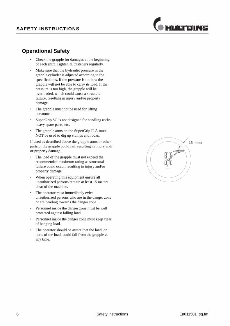
• When operating this equipment ensure all unauthorized persons remain at least 15 meters clear of the machine.
• The operator must immediately evict unauthorized persons who are in the danger zone or are heading towards the danger zone
• Personnel inside the danger zone must be well protected against falling load.
• Personnel inside the danger zone must keep clear of hanging load.
• The operator should be aware that the load, or parts of the load, could fall from the grapple at any time.
15 meter
SAFETY INSTRUCTIONS
En011501_sg.fm Safety instructions 7
Maintenance safety
• The machine's condition must be checked regularly, daily inspections shall be performed and any deficiencies must be corrected. The machine shall be maintained in such condition that the operator or other persons not exposed to danger or accidents.
• Never commit any service on the equipment without proper knowledge. All service and repairs in electrical and hydaulical systems should be carried out by qualified personnel only.
• Repair any damages immediate when discovered. Do not use the equipment until any damages are rectified.
• Before performing any maintenance or service work, lower the grapple to the ground and shut off the engine. Turn off any master shut-offs and do not allow personnel in the cab.
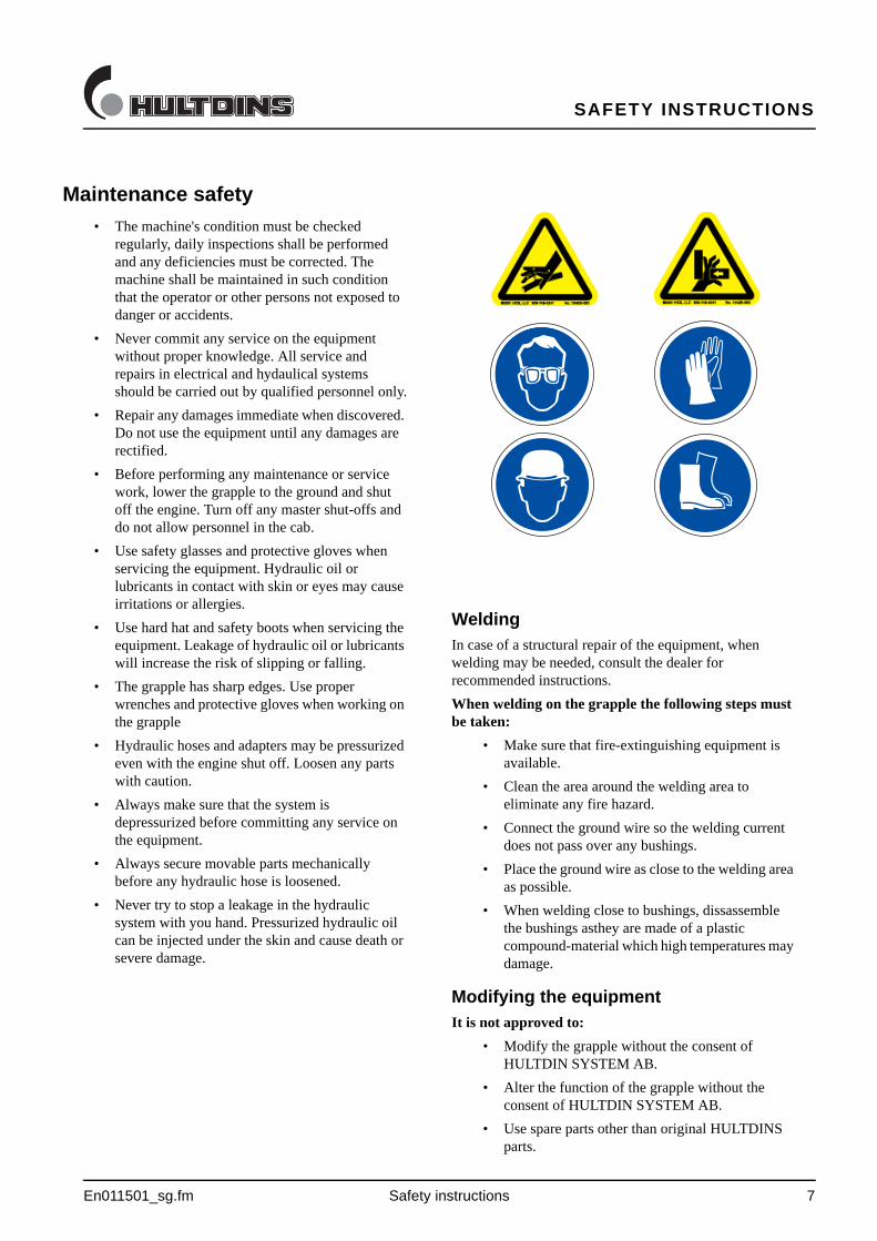
• Use safety glasses and protective gloves when servicing the equipment. Hydraulic oil or lubricants in contact with skin or eyes may cause irritations or allergies.
• Use hard hat and safety boots when servicing the equipment. Leakage of hydraulic oil or lubricants will increase the risk of slipping or falling.
• The grapple has sharp edges. Use proper wrenches and protective gloves when working on the grapple
• Hydraulic hoses and adapters may be pressurized even with the engine shut off. Loosen any parts with caution.
• Always make sure that the system is depressurized before committing any service on the equipment.
• Always secure movable parts mechanically before any hydraulic hose is loosened.
• Never try to stop a leakage in the hydraulic system with you hand. Pressurized hydraulic oil can be injected under the skin and cause death or severe damage.
WeldingIn case of a structural repair of the equipment, when welding may be needed, consult the dealer for recommended instructions.
When welding on the grapple the following steps must be taken:
• Make sure that fire-extinguishing equipment is available.
• Clean the area around the welding area to eliminate any fire hazard.
• Connect the ground wire so the welding current does not pass over any bushings.
• Place the ground wire as close to the welding area as possible.
• When welding close to bushings, dissassemble the bushings asthey are made of a plastic compound-material which high temperatures may damage.
Modifying the equipmentIt is not approved to:
• Modify the grapple without the consent of HULTDIN SYSTEM AB.
• Alter the function of the grapple without the consent of HULTDIN SYSTEM AB.
• Use spare parts other than original HULTDINS parts.

MAIN PARTS
8 SuperGrip SG II En011002_sg2.fm
Main Parts
The SuperGrip SG II is made up of the following main parts. All parts are replaceable.
Fig. 1 Main parts SuperGrip SG II
1
2
3
4
9
6
7
8
5
10
4
1 Frame
2 Female grapple arm
3 Male grapple arm
4 Pin-joint, frame-female grapple arm
5 Pin-joint system, frame-male grapple arm
6 Rod
7 Hydraulic cylinder
8 Pin-joint system, grapple arm-rod-hydraulic cylinder
9 Pin-joint system, rod-male grapple arm
10 Pin-joint system, piston rod-male grapple arm
PRODUCT DESCRIPTION
En011003_sg2.fm SuperGrip SG II 9
Märkning SuperGrip SG II
Product description
The SuperGrip SG II is a short wood grapple that is generally mounted on cranes/booms intended for on road- and off road-vehicles. The SuperGrip SG II is only intended to be used for timber, cut-to-length, whole-tree and waste wood systems.
The SuperGrip SG II must not be used when lifting rocks or when performing equivalent lifts as there is a risk that the grapple arms or other parts of the grapple may fail, which could result in injury or damaged equipment.
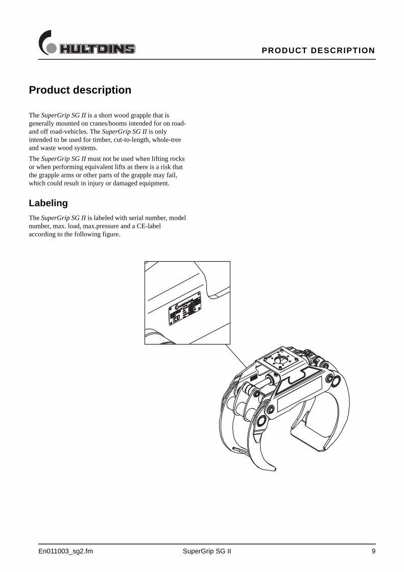
Labeling
The SuperGrip SG II is labeled with serial number, model number, max. load, max.pressure and a CE-label according to the following figure.
TECHNICAL DATA
10 SuperGrip SG II En011504_sg2.fm
Technical data
SuperGrip SG II
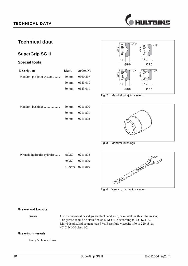
Special tools
Description Diam. Order. No
Mandrel, pin-joint system......... 50 mm 0660 207
60 mm 0683 010
80 mm 0683 011
Mandrel, bushings..................... 50 mm 0711 800
60 mm 0711 801
80 mm 0711 802
Wrench, hydraulic cylinder....... ø80/50 0711 808
ø90/50 0711 809
ø100/50 0711 810
Fig. 2 Mandrel, pin-joint system
��
�
��
����
�
�
��
�
�
��
����
�
�
��
��
�
��
����
�
�
��
��
�
��
����
�
�
��
��� ���
� � ���
Fig. 3 Mandrel, bushings
Fig. 4 Wrench, hydraulic cylinder
Grease and Loc-tite
Grease Use a mineral oil based grease thickened with, or mixable with a lithium soap. The grease should be classified as L-XCCIB2 according to ISO 6743-9. Molybdendisulfid content max 3 %. Base fluid viscosity 170 to 220 cSt at 40°C. NLGI class 1-2.
Greasing intervals
Every 50 hours of use
TECHNICAL DATA
En011504_sg2.fm SuperGrip SG II 11
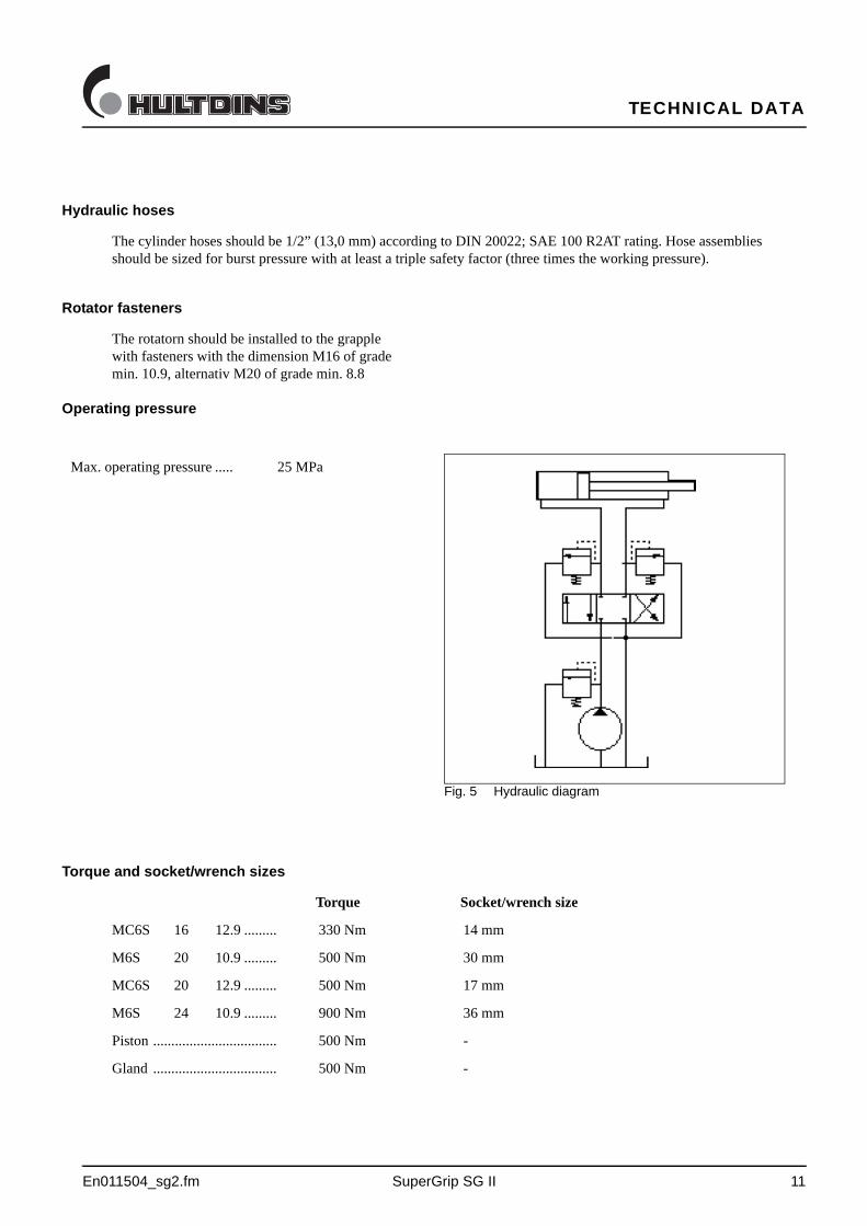
Hydraulic hoses
The cylinder hoses should be 1/2” (13,0 mm) according to DIN 20022; SAE 100 R2AT rating. Hose assemblies should be sized for burst pressure with at least a triple safety factor (three times the working pressure).
Rotator fasteners
The rotatorn should be installed to the grapple with fasteners with the dimension M16 of grade min. 10.9, alternativ M20 of grade min. 8.8
Operating pressure
Max. operating pressure ..... 25 MPa
Fig. 5 Hydraulic diagram
Torque and socket/wrench sizes
Torque Socket/wrench size
MC6S 16 12.9 ......... 330 Nm 14 mm
M6S 20 10.9 ......... 500 Nm 30 mm
MC6S 20 12.9 ......... 500 Nm 17 mm
M6S 24 10.9 ......... 900 Nm 36 mm
Piston .................................. 500 Nm -
Gland .................................. 500 Nm -
TECHNICAL DATA
12 SG II En011504a_sg2.fm
Technical data
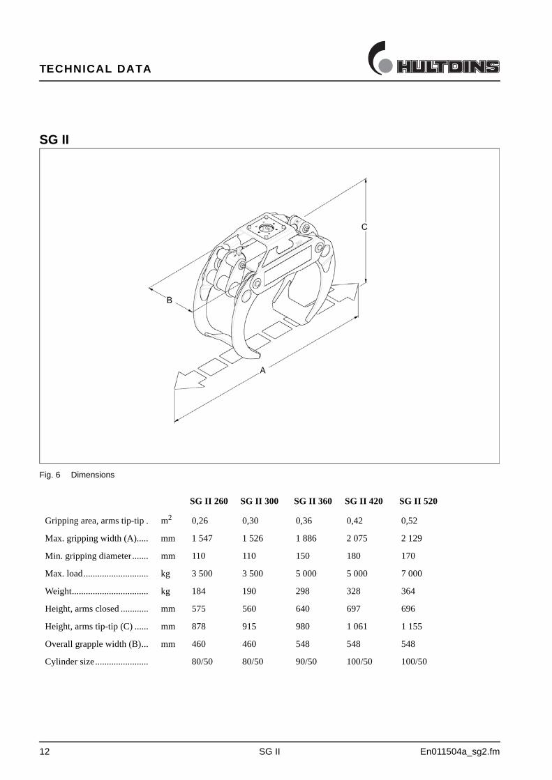
SG II
Fig. 6 Dimensions
Metric units SG II 260 SG II 300 SG II 360 SG II 420 SG II 520
Gripping area, arms tip-tip . m2 0,26 0,30 0,36 0,42 0,52
Max. gripping width (A)..... mm 1 547 1 526 1 886 2 075 2 129
Min. gripping diameter....... mm 110 110 150 180 170
Max. load............................ kg 3 500 3 500 5 000 5 000 7 000
Weight................................. kg 184 190 298 328 364
Height, arms closed ............ mm 575 560 640 697 696
Height, arms tip-tip (C) ...... mm 878 915 980 1 061 1 155
Overall grapple width (B)... mm 460 460 548 548 548
Cylinder size....................... 80/50 80/50 90/50 100/50 100/50
TECHNICAL DATA
En011504b_sg2.fm SG II R 13
Technical data
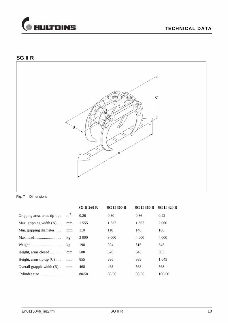
SG II R
Fig. 7 Dimensions
Metric units SG II 260 R SG II 300 R SG II 360 R SG II 420 R
Gripping area, arms tip-tip . m2 0,26 0,30 0,36 0,42
Max. gripping width (A)..... mm 1 555 1 537 1 867 2 060
Min. gripping diameter....... mm 110 110 146 180
Max. load............................ kg 3 000 3 000 4 000 4 000
Weight................................. kg 198 204 316 345
Height, arms closed ............ mm 580 570 645 693
Height, arms tip-tip (C) ...... mm 855 886 939 1 043
Overall grapple width (B)... mm 468 468 568 568
Cylinder size....................... 80/50 80/50 90/50 100/50
TECHNICAL DATA
14 SG II S En011504c_sg2.fm
Technical data
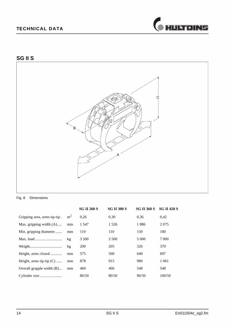
SG II S
Fig. 8 Dimensions
Metric units SG II 260 S SG II 300 S SG II 360 S SG II 420 S
Gripping area, arms tip-tip . m2 0,26 0,30 0,36 0,42
Max. gripping width (A)..... mm 1 547 1 526 1 886 2 075
Min. gripping diameter....... mm 110 110 150 180
Max. load............................ kg 3 500 3 500 5 000 7 000
Weight................................. kg 200 205 326 370
Height, arms closed ............ mm 575 560 640 697
Height, arms tip-tip (C) ...... mm 878 915 980 1 061
Overall grapple width (B)... mm 460 460 548 548
Cylinder size....................... 80/50 80/50 90/50 100/50

TECHNICAL DATA
En011504d_sg2.fm SG II A 15
Technical data
SG II A
Fig. 9 Dimensions
Metric units SG II 260 A SG II 300 A SG II 360 A SG II 420 A
Gripping area, arms tip-tip . m2 0,26 0,30 0,36 0,42
Max. gripping width (A)..... mm 1 520 1 485 1 840 2 037
Min. gripping diameter....... mm 110 110 150 180
Max. load............................ kg 3 500 3 500 5 000 5 500
Weight................................. kg 200 205 326 370
Height, arms closed ............ mm 583 579 689 695
Height, arms tip-tip (C) ...... mm 945 975 1060 1129
Overall grapple width (B)... mm 460 460 548 548
Cylinder size....................... 80/50 80/50 90/50 100/50
FUNCTIONAL DESCRIPTION
16 SuperGrip SG II En011005_sg2.fm
Functional description
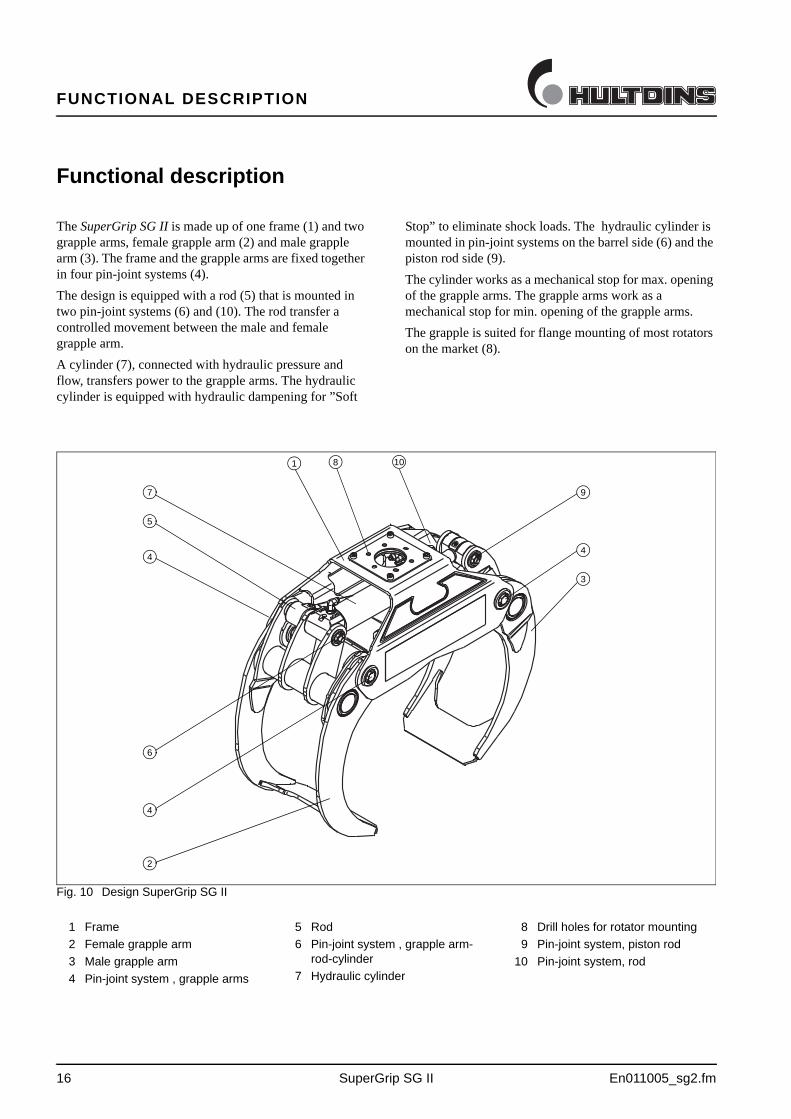
The SuperGrip SG II is made up of one frame (1) and two grapple arms, female grapple arm (2) and male grapple arm (3). The frame and the grapple arms are fixed together in four pin-joint systems (4).
The design is equipped with a rod (5) that is mounted in two pin-joint systems (6) and (10). The rod transfer a controlled movement between the male and female grapple arm.
A cylinder (7), connected with hydraulic pressure and flow, transfers power to the grapple arms. The hydraulic cylinder is equipped with hydraulic dampening for ”Soft
Stop” to eliminate shock loads. The hydraulic cylinder is mounted in pin-joint systems on the barrel side (6) and the piston rod side (9).
The cylinder works as a mechanical stop for max. opening of the grapple arms. The grapple arms work as a mechanical stop for min. opening of the grapple arms.
The grapple is suited for flange mounting of most rotators on the market (8).
Fig. 10 Design SuperGrip SG II
1
2
3
4
10
5
7
6
4
9
4
8
1 Frame
2 Female grapple arm
3 Male grapple arm
4 Pin-joint system , grapple arms
5 Rod
6 Pin-joint system , grapple arm-rod-cylinder
7 Hydraulic cylinder
8 Drill holes for rotator mounting
9 Pin-joint system, piston rod
10 Pin-joint system, rod
INSTALLATION
En010606a_sg2.fm SuperGrip SG II 17
Installation
Important!
All service and repairs should be carried out by qualified personnel or an authorized repair shop with suitable tools and lifting devices.
Installing the rotator
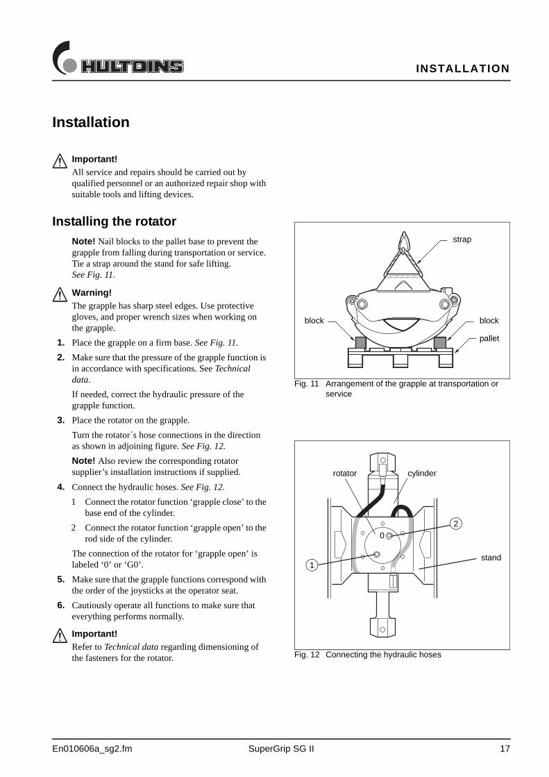
Note! Nail blocks to the pallet base to prevent the grapple from falling during transportation or service. Tie a strap around the stand for safe lifting. See Fig. 11.
Fig. 11 Arrangement of the grapple at transportation or service
strap
block
pallet
block
Warning!
The grapple has sharp steel edges. Use protective gloves, and proper wrench sizes when working on the grapple.
1. Place the grapple on a firm base. See Fig. 11.
2. Make sure that the pressure of the grapple function is in accordance with specifications. See Technical data.
If needed, correct the hydraulic pressure of the grapple function.
3. Place the rotator on the grapple.
Turn the rotator´s hose connections in the direction as shown in adjoining figure. See Fig. 12.
Note! Also review the corresponding rotator supplier’s installation instructions if supplied.
Fig. 12 Connecting the hydraulic hoses
2
1stand
rotator cylinder
0
4. Connect the hydraulic hoses. See Fig. 12.
1 Connect the rotator function ‘grapple close’ to the base end of the cylinder.
2 Connect the rotator function ‘grapple open’ to the rod side of the cylinder.
The connection of the rotator for ‘grapple open’ is labeled ‘0’ or ‘G0’.
5. Make sure that the grapple functions correspond with the order of the joysticks at the operator seat.
6. Cautiously operate all functions to make sure that everything performs normally.
Important!
Refer to Technical data regarding dimensioning of the fasteners for the rotator.
MAINTENANCE INSTRUCTIONS
18 SuperGrip SG II En011007_sg2.FM
Maintenance instructions
Every 10 hours of operation (every day)
• Clear the grapple so that snow, bark or any other debris does not limit the function of the grapple.
• Make sure that the hydraulic hoses are not damaged
• Make sure that there is no damages or crackings on the grapple.
• Make sure that there is no leakage on the grapple.Tighten any loose items and repair any damages.
Important!
Check the equipment for damages at the beginning of each shift.
Important!
All service and repairs should be performed by qualified personnel only
Important!
Never adjust any hydraulic pressures without using a pressure gauge
Important!
Consider the environment. Plug all open connections to avoid unnecessary spill of oil
Warning!
Never try to stop a hydraulic leakage from a broken hose or any other component with your hand. Oil injection into the body can cause injury
MAINTENANCE INSTRUCTIONS
En011007_sg2.FM SuperGrip SG II 19
Every 50 hours of operation (every week)
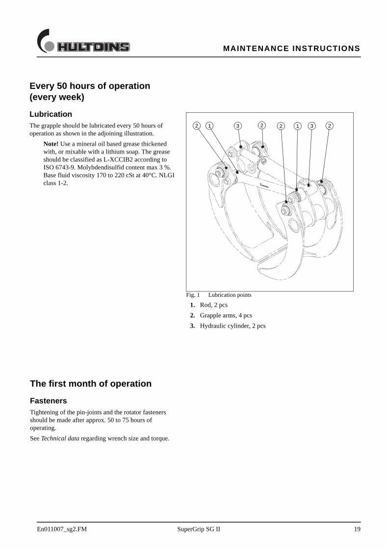
LubricationThe grapple should be lubricated every 50 hours of operation as shown in the adjoining illustration.
Note! Use a mineral oil based grease thickened with, or mixable with a lithium soap. The grease should be classified as L-XCCIB2 according to ISO 6743-9. Molybdendisulfid content max 3 %. Base fluid viscosity 170 to 220 cSt at 40°C. NLGI class 1-2.
The first month of operation
FastenersTightening of the pin-joints and the rotator fasteners should be made after approx. 50 to 75 hours of operating.
See Technical data regarding wrench size and torque.
Fig. 1 Lubrication points
1. Rod, 2 pcs
2. Grapple arms, 4 pcs
3. Hydraulic cylinder, 2 pcs
1 232 1 32 2

Hultdins Inc.P.O. Box 1205, 22 Morton Ave. East
Brantford, Ontario, Canada N3T 5T3
Tel (519) 754-0044, Fax (519) 754-1569
E-mail: [email protected]
Hultdin System ABSkolgatan 12, SE-930 70 MALÅ, Sweden
Tel +46 953 418 00, Fax +46 953 418 01
E-mail: [email protected]
0115 - 7000300-EN