Super SMA Connectors End Launch Connector...
8
Southwest Microwave, Inc. Tempe, Arizona 85284 USA 480-783-0201 www.southwestmicrowave.com Cable Connectors Launch Accessories Installation and Tools SSMA Connectors End Launch Connectors 2.40 mm Connectors Adapters 2.92 mm Connectors TNC Connectors Super SMA Connectors N Series Connectors 50 End Launch Connector Series Index End Launch Connectors (67 GHz) ........... Page Specifications ........................... 51 Introduction ............................. 52 Installation Procedure ..................... 53 End Launch Connector Dimensions ........... 54 Connector Numbers ....................... 55 Typical Test Data ......................... 56
Transcript of Super SMA Connectors End Launch Connector...
Southwest Microwave, Inc. Tempe, Arizona 85284 USA 480-783-0201 www.southwestmicrowave.com
Cab
leC
onne
ctor
sLa
unch
Acc
esso
ries
Inst
alla
tion
and
Tool
sS
SMA
Con
nect
ors
End
Lau
nch
Con
nect
ors
2.4
0 m
m
Con
nect
ors
Ada
pter
s 2
.92
mm
Con
nect
ors
TNC
Con
nect
ors
Supe
r SM
AC
onne
ctor
s N
Ser
ies
Con
nect
ors
50
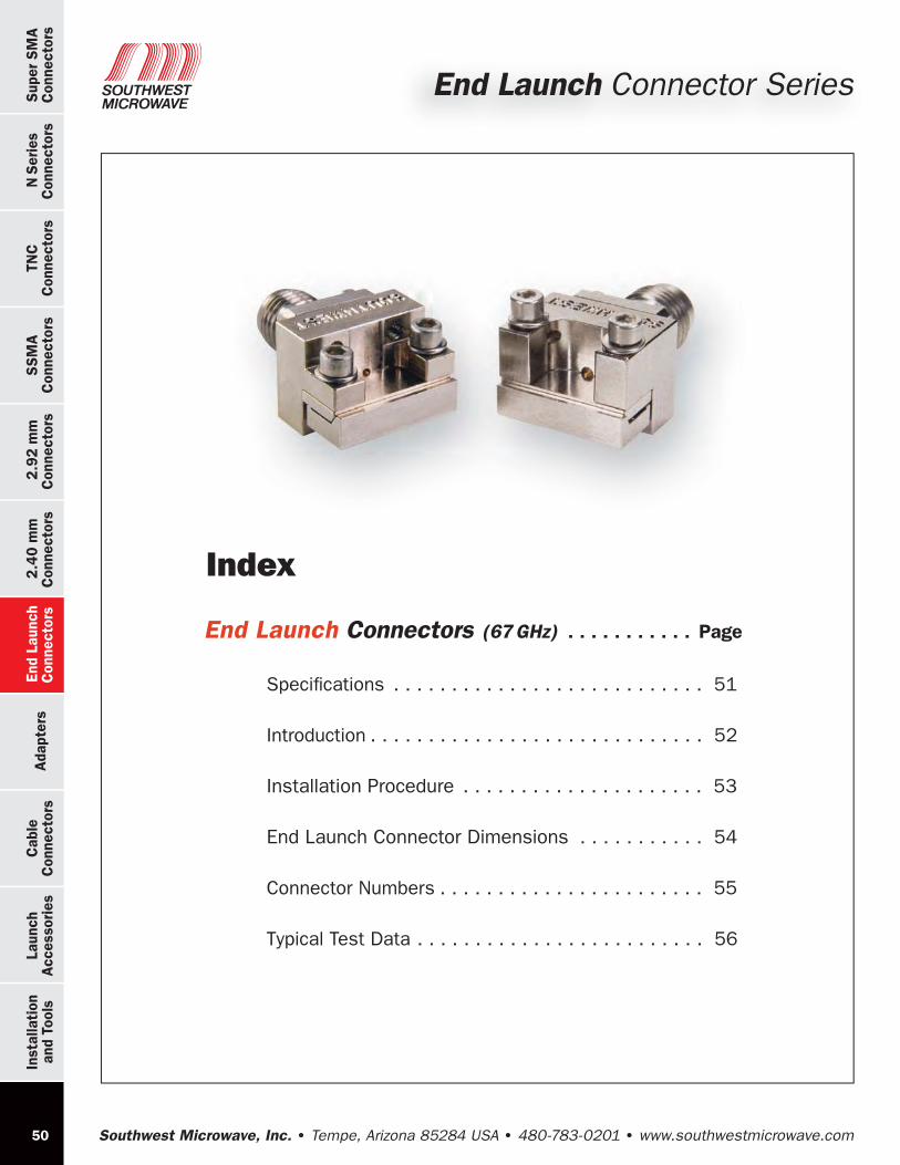
End Launch Connector Series
Index
End Launch Connectors (67 GHz) . . . . . . . . . . . Page
Specifications . . . . . . . . . . . . . . . . . . . . . . . . . . . 51
Introduction . . . . . . . . . . . . . . . . . . . . . . . . . . . . . 52
Installation Procedure . . . . . . . . . . . . . . . . . . . . . 53
End Launch Connector Dimensions . . . . . . . . . . . 54
Connector Numbers . . . . . . . . . . . . . . . . . . . . . . . 55
Typical Test Data . . . . . . . . . . . . . . . . . . . . . . . . . 56

Southwest Microwave, Inc. Tempe, Arizona 85284 USA 480-783-0201 www.southwestmicrowave.com
TNC
Connectors
N Series
Connectors
Super SMA
Connectors
SSM
AC
onnectors 2.92 m
mC
onnectors 2.40 m
m
Connectors
Adapters
End LaunchC
onnectorsC
ableC
onnectorsInstallation
and ToolsLaunch
Accessories
51
End Launch Connectors
Specifications
Applications
Grounded Coplanar Microstrip with Top Ground Launch
Electrical: Mode Free Through: 27.0 GHz (SMA) 40.0 GHz (2.92 mm) 50.0 GHz (2.40 mm) 67.0 GHz (1.85 mm)
Low VSWR
Low Insertion Loss
Materials / Construction: Connector:
(see appropriate connector section for materials & construction)
Transition Block & Clamp Plates:
Housing: Brass Alloy UNS C36000 Per ASTM B16,
Nickel Plate Per ASTM 2404B
Transition Pin: Beryllium Copper (BeCu) Per UNS C36000 Per ASTM B16,
Gold Plate Per MIL-G-45204 or ASTM B488
Dielectric: Virgin PTFE Fluorocarbon Per ASTM D1710
Fasteners: Per ANSI B18.3
Board Launch Design Assistance Available. Contact Factory.
Standard 3/8” Square Flange Connector
Clamp Plates
Transition Block

Southwest Microwave, Inc. Tempe, Arizona 85284 USA 480-783-0201 www.southwestmicrowave.com
Cab
leC
onne
ctor
sLa
unch
Acc
esso
ries
Inst
alla
tion
and
Tool
sS
SMA
Con
nect
ors
End
Lau
nch
Con
nect
ors
2.4
0 m
m
Con
nect
ors
Ada
pter
s 2
.92
mm
Con
nect
ors
TNC
Con
nect
ors
Supe
r SM
AC
onne
ctor
s N
Ser
ies
Con
nect
ors
52
Introduction Southwest Microwave’s High Performance End Launch Connectors are designed to provide Low VSWR, wideband response to 67 GHz for single-layer or multi-layer printed circuit boards where the microwave layer is on top. They are ideally suited for high frequency chip set evaluation/demo boards, test fixtures and board characterization.
Features:
Now available in: SMA (27 GHz), 2.92 mm (40 GHz), 2.40 mm (50 GHz) and 1.85 mm (67 GHz)
Multiple launch configurations to optimize match to circuit
Optimum performance when board launch geometry is grounded coplanar (CPWG) or top ground microstrip
Unique clamping mechanism accommodates a wide range of board thicknesses (up to .110”) while providing a continuous ground connection between end launch and circuit board.
Launch overhang that allows ground to be picked up close to the launch point
Universal, robust & reusable
No soldering required
Connectors ship fully assembled (board not included)
End Launch Connectors
Examples of Applications
Chip set evaluation demo boards.
Board characterization.
Internal board launch (not limited to perimeter board edge).
Custom flanges available.
Southwest Microwave, Inc. Tempe, Arizona 85284 USA 480-783-0201 www.southwestmicrowave.com
TNC
Connectors
N Series
Connectors
Super SMA
Connectors
SSM
AC
onnectors 2.92 m
mC
onnectors 2.40 m
m
Connectors
Adapters
End LaunchC
onnectorsC
ableC
onnectorsInstallation
and ToolsLaunch
Accessories
53
End Launch ConnectorsInstallation
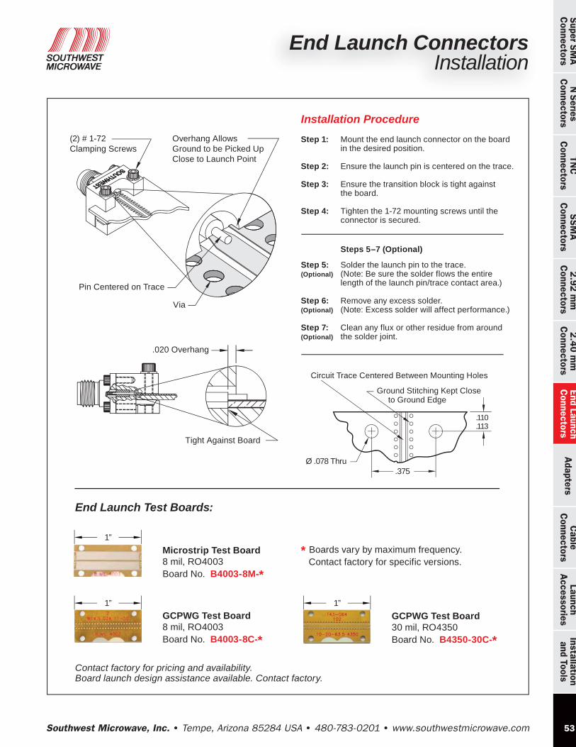
End Launch Test Boards:
Contact factory for pricing and availability.Board launch design assistance available. Contact factory.
Installation Procedure
Step 1: Mount the end launch connector on the board in the desired position.
Step 2: Ensure the launch pin is centered on the trace.
Step 3: Ensure the transition block is tight against the board.
Step 4: Tighten the 1-72 mounting screws until the connector is secured.
Steps 5–7 (Optional)
Step 5: Solder the launch pin to the trace. (Optional) (Note: Be sure the solder flows the entire length of the launch pin/trace contact area.)
Step 6: Remove any excess solder. (Optional) (Note: Excess solder will affect performance.)
Step 7: Clean any flux or other residue from around (Optional) the solder joint.
.020 Overhang
Tight Against Board
Pin Centered on Trace
Via
(2) # 1-72 Clamping Screws
Overhang Allows Ground to be Picked Up Close to Launch Point
Circuit Trace Centered Between Mounting Holes
Ground Stitching Kept Close to Ground Edge
.375Ø .078 Thru
.110
.113
1”
Microstrip Test Board 8 mil, RO4003Board No. B4003-8M-*
* Boards vary by maximum frequency. Contact factory for specific versions.
1”
GCPWG Test Board 30 mil, RO4350Board No. B4350-30C-*
1”GCPWG Test Board 8 mil, RO4003Board No. B4003-8C-*

Southwest Microwave, Inc. Tempe, Arizona 85284 USA 480-783-0201 www.southwestmicrowave.com
Cab
leC
onne
ctor
sLa
unch
Acc
esso
ries
Inst
alla
tion
and
Tool
sS
SMA
Con
nect
ors
End
Lau
nch
Con
nect
ors
2.4
0 m
m
Con
nect
ors
Ada
pter
s 2
.92
mm
Con
nect
ors
TNC
Con
nect
ors
Supe
r SM
AC
onne
ctor
s N
Ser
ies
Con
nect
ors
54
End Launch ConnectorsDimensions
End Launch Connector Dimensions
Field Replaceable .375” Square Flange Connectors are Available in Male or Female Configurations.
Standard Profile Connectors
Low Profile Connectors
(4) # 0-80 SHCS (2) # 1-72 SHCS
(2) # 1-72 SHCS(4) # 0-80 SHCS
Southwest Microwave, Inc. Tempe, Arizona 85284 USA 480-783-0201 www.southwestmicrowave.com
TNC
Connectors
N Series
Connectors
Super SMA
Connectors
SSM
AC
onnectors 2.92 m
mC
onnectors 2.40 m
m
Connectors
Adapters
End LaunchC
onnectorsC
ableC
onnectorsInstallation
and ToolsLaunch
Accessories
55
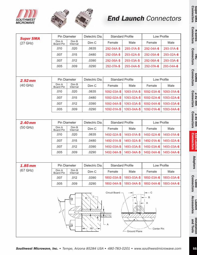
Super SMA (27 GHz)
Dim C
.0635
.0480
.020
.015
Dim ABoard Pin
Dim BInternal
.010
.007
Female
292-04A-5
292-05A-5
Male
293-01A-5
293-02A-5
.0390.012.007 292-06A-5 293-03A-5
.0290.009.005 292-07A-5 293-04A-5
Standard ProfileDielectric Dia.Pin Diameter
2.92 mm (40 GHz)
Dim C
.0635
.0480
Dim BInternal
.020
.015
Dim ABoard Pin
.010
.007
Female
1092-03A-5
1092-02A-5
Male
1093-01A-5
1093-02A-5
.0390.012.007 1092-04A-5 1093-03A-5
.0290.009.005 1092-01A-5 1093-04A-5
Standard ProfileDielectric Dia.Pin Diameter
2.40 mm (50 GHz)
Dim C
.0635
.0480
Dim BInternal
.020
.015
Dim ABoard Pin
.010
.007
Female
1492-02A-5
1492-01A-5
Male
1493-01A-5
1493-02A-5
.0390.012.007 1492-03A-5 1493-03A-5
.0290.009.005 1492-04A-5 1493-04A-5
Standard Profile
Female
292-04A-6
292-05A-6
Male
293-01A-6
293-02A-6
292-06A-6 293-03A-6
292-07A-6 293-04A-6
Low Profile
Female
1092-03A-6
1092-02A-6
Male
1093-01A-6
1093-02A-6
1092-04A-6 1093-03A-6
1092-01A-6 1093-04A-6
Low Profile
Female
1492-02A-6
1492-01A-6
Male
1493-01A-6
1493-02A-6
1492-03A-6 1493-03A-6
1492-04A-6 1493-04A-6
Low ProfileDielectric Dia.Pin Diameter
1.85 mm (67 GHz)
Dim C Dim BInternal
Dim ABoard Pin Female
1892-03A-5
Male
1893-03A-5.0390.012.007
Standard Profile
Female
1892-03A-6
Male
1893-03A-6
1892-04A-5 1893-04A-5.0290.009.005 1892-04A-6 1893-04A-6
Low ProfileDielectric Dia.Pin Diameter
End Launch Connectors
Ground PlaneCenter Pin
Circuit Board

Southwest Microwave, Inc. Tempe, Arizona 85284 USA 480-783-0201 www.southwestmicrowave.com
Cab
leC
onne
ctor
sLa
unch
Acc
esso
ries
Inst
alla
tion
and
Tool
sS
SMA
Con
nect
ors
End
Lau
nch
Con
nect
ors
2.4
0 m
m
Con
nect
ors
Ada
pter
s 2
.92
mm
Con
nect
ors
TNC
Con
nect
ors
Supe
r SM
AC
onne
ctor
s N
Ser
ies
Con
nect
ors
56
Coplanar Test DataEnd Launch Connectors on a Coplanar Board Below are test results to 50 GHz for two 1492-04A-5 end launch connectors on a .008" Rogers RO4003 coplanar board. The plot shows both VSWR and insertion loss for the test board and the two connectors. Similar boards are used for the other launch geometries.
Connector No. 1492-04A-5
1.58 is the maximum for two 1492-04A-5 End Launch Connectors on a SMI Microstrip test board using .008” Rogers RO4003 coplanar board.
-1.00
-2.00
0.00
1.400
1.200
1.000
1.600
0.0 25.0 50.0
S 11
(VSW
R) -3.00
S21 (dB)
Frequency (GHz)
End Launch Connectors on a Coplanar Board (Connector No. 1492-04A-5)
End Launch ConnectorsCoplanar Test Data
1.58
Southwest Microwave, Inc. Tempe, Arizona 85284 USA 480-783-0201 www.southwestmicrowave.com
TNC
Connectors
N Series
Connectors
Super SMA
Connectors
SSM
AC
onnectors 2.92 m
mC
onnectors 2.40 m
m
Connectors
Adapters
End LaunchC
onnectorsC
ableC
onnectorsInstallation
and ToolsLaunch
Accessories
57
1.400
1.200
1.000
0.0 33.5 67.0
S 11
(VSW
R)
Frequency (GHz)
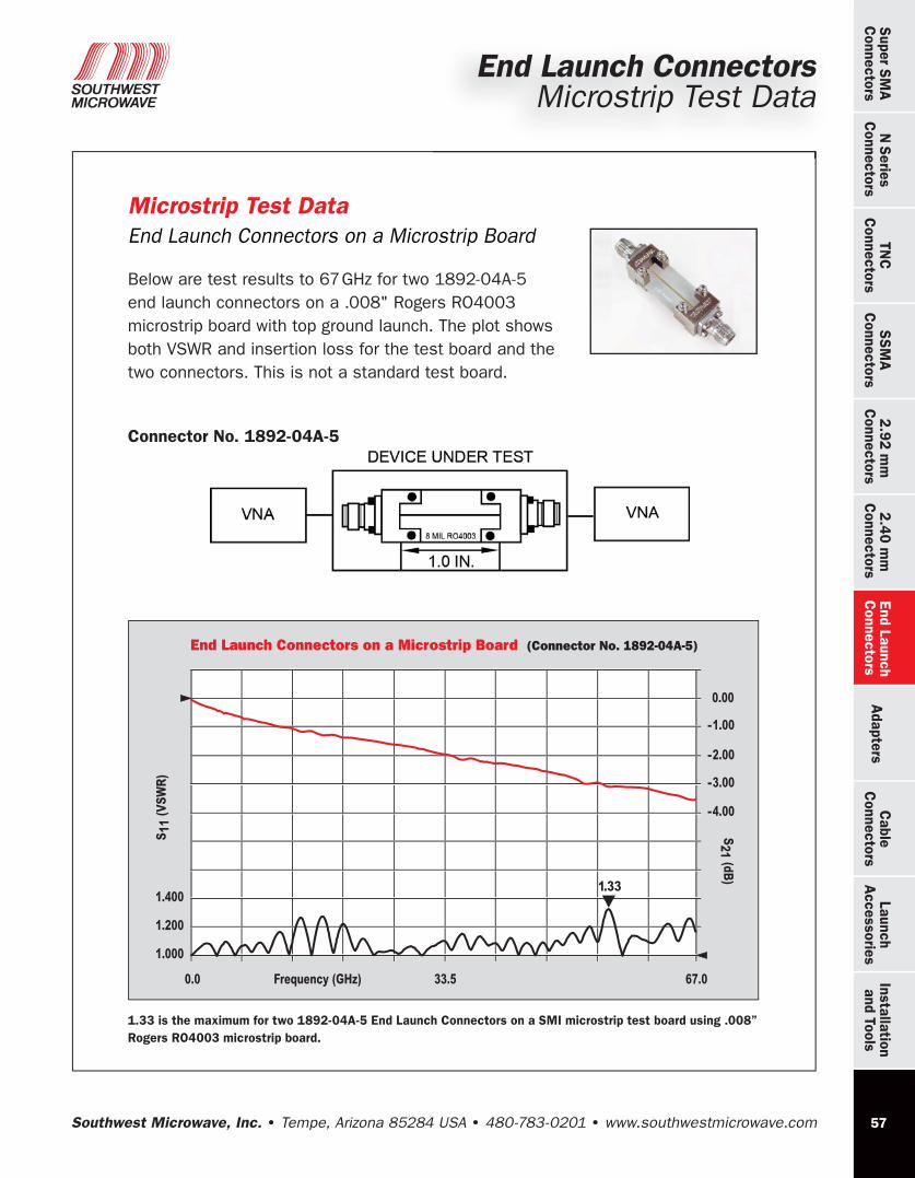
End Launch Connectors on a Microstrip Board (Connector No. 1892-04A-5)
-1.00
-2.00
0.00
-3.00
-4.00
S21 (dB)
1.33
Microstrip Test DataEnd Launch Connectors on a Microstrip Board Below are test results to 67 GHz for two 1892-04A-5 end launch connectors on a .008" Rogers RO4003 microstrip board with top ground launch. The plot shows both VSWR and insertion loss for the test board and the two connectors. This is not a standard test board.
Connector No. 1892-04A-5
1.33 is the maximum for two 1892-04A-5 End Launch Connectors on a SMI microstrip test board using .008” Rogers RO4003 microstrip board.
End Launch ConnectorsMicrostrip Test Data