
Super-precision angular contact ball bearings: High-capacity · Machine tools and other precision...
48
Super-precision angular contact ball bearings: High-capacity 72 .. D (E 200) series
-
Upload
trankhuong -
Category
Documents
-
view
216 -
download
0
Transcript of Super-precision angular contact ball bearings: High-capacity · Machine tools and other precision...

Super-precision angular contact ball bearings: High-capacity72 .. D (E 200) series

Contents
A Product information
SKF high-capacity super-precision
angular contact ball bearings . . . . . . 3
An extended range – a growing
assortment . . . . . . . . . . . . . . . . . . . . . 4
Bearing design . . . . . . . . . . . . . . . . . . . 5
Bearing series . . . . . . . . . . . . . . . . . . . 6
Bearing variants . . . . . . . . . . . . . . . . . . 6
Single bearings and matched
bearing sets . . . . . . . . . . . . . . . . . . . . . 7
Applications . . . . . . . . . . . . . . . . . . . . 8
B Recommendations
Bearing arrangement design . . . . . . . 10
Single bearings. . . . . . . . . . . . . . . . . . . 10
Bearing sets . . . . . . . . . . . . . . . . . . . . . 10
Type of arrangement . . . . . . . . . . . . . . 11
Application examples . . . . . . . . . . . . . . 12
Lubrication . . . . . . . . . . . . . . . . . . . . . 14
Grease lubrication for open bearings . . 14
Sealed bearings . . . . . . . . . . . . . . . . . . 15
Running-in of open and sealed,
grease lubricated bearings . . . . . . . . . . 15
Oil lubrication for open bearings . . . . . . 16
C Product data
Bearing data – general . . . . . . . . . . . . 18
Boundary dimensions . . . . . . . . . . . . . 18
Chamfer dimensions. . . . . . . . . . . . . . . 18
Tolerances . . . . . . . . . . . . . . . . . . . . . . 18
Bearing preload . . . . . . . . . . . . . . . . . . 18
Bearing axial stiffness. . . . . . . . . . . . . . 22
Fitting and clamping of bearing rings . . 24
Load carrying capacity of bearing sets . 25
Equivalent bearing loads . . . . . . . . . . . 26
Attainable speeds . . . . . . . . . . . . . . . . . 26
Cages . . . . . . . . . . . . . . . . . . . . . . . . . . 26
Seals . . . . . . . . . . . . . . . . . . . . . . . . . . 27
Materials . . . . . . . . . . . . . . . . . . . . . . . 27
Heat treatment . . . . . . . . . . . . . . . . . . . 27
Marking of bearings and bearing sets . . 28
Packaging . . . . . . . . . . . . . . . . . . . . . . . 29
Designation system . . . . . . . . . . . . . . . 29
Product tables . . . . . . . . . . . . . . . . . . 32
D Additional information
Setting the highest standard for
precision bearings . . . . . . . . . . . . . . . 42
Super-precision angular contact ball
bearings . . . . . . . . . . . . . . . . . . . . . . . . 42
Super-precision cylindrical roller
bearings . . . . . . . . . . . . . . . . . . . . . . . . 43
Super-precision double direction angular
contact thrust ball bearings . . . . . . . . . 43
Super-precision angular contact thrust
ball bearings for screw drives . . . . . . . . 43
Super-precision axial-radial cylindrical
roller bearings . . . . . . . . . . . . . . . . . . . 43
SKF – the knowledge engineering
company . . . . . . . . . . . . . . . . . . . . . . . 46
2

Machine tools and other precision applica-
tions require superior bearing performance.
In these applications, high system rigidity is
one of the main performance challenges, as
the magnitude of elastic deformation under
load determines the productivity and accur-
acy of the equipment. Parallel Kinematic
Machines (PKM), for example, are known for
their ability to provide high structural rigidity
and high dynamic capacities. But this is only
possible when the bearings inside these
machines step up to the challenge. SKF has
developed a new generation of super-preci-
sion angular contact ball bearings that can
meet these ever-increasing performance
requirements. The ability of the new design
super-precision angular contact ball bear-
ings in the 72 .. D (E 200)1) series to accom-
modate heavy loads, and still provide a high
degree of rigidity, makes them an excellent
solution for these and similar applications.
SKF high-capacity super-precision angular contact ball bearings
SKF bearings in the 72 .. D (E 200) series
are characterized by:
• high load carrying capacity
• high degree of stiffness
• extended bearing service life
• low heat generation
• low noise and vibration levels
The bearings provide high reliability and
superior accuracy for applications such as
Parallel Kinematic Machines (PKM), lathe
spindles, grinding and boring machines,
high-speed dynamometers and
turbochargers.
1) Where applicable, designations in parentheses and italics refer to the corresponding SNFA equivalent.
A
3

An extended range – a growing assortment
The growing SKF assortment of super-
precision bearings is now complemented by
angular contact ball bearings in the 72 .. D
(E 200) series. The extended range of bear-
ings in this series now accommodates shaft
diameters ranging from 7 to 140 mm. And,
there is also a relubrication-free, sealed
bearing series, available on request.
To accommodate the diverse operating
requirements of precision applications,
bearings in the 72 .. D (E 200) series are
manufactured to two tolerance classes and
with two contact angles. Those suitable for
universal matching or mounting in sets are
produced to four preload classes, to meet
almost all application requirements in terms
of speed and rigidity. Matched bearing sets
with a special preload can be supplied on
request. For many sizes, the bearings are
available, standard, with a choice of two ball
materials. The most common sizes have a
polyetheretherketone (PEEK) cage to
accommodate extended operating
temperatures.
Bearings in the 72 .. D (E 200) series, like
all angular contact ball bearings, are nearly
always adjusted against a second bearing to
balance the counterforces. To accommodate
heavier loads and axial loads in both direc-
tions, the bearings are used in sets consist-
ing typically of up to four bearings.
SKF super-precision angular contact ball bearings: 72 .. D (E 200) series
Features
• High number of large balls
• Optimized chamfer design
• ISO dimension series 02
• Asymmetrical outer ring
• Lightweight cage (phenolic resin or PEEK)
• High-temperature PEEK cage, for most common sizes
• High-speed grease, for sealed variant
• Non-contact seals, for sealed variant
Benefits
• High load carrying capacity, high degree of rigidity
• Facilitated mounting
• Large cross section, robust
• Accommodates radial loads, and axial loads in one direction
• Low friction, good lubricant supply to ball/raceway contact areas
• Accommodates operating temperatures up to 150 °C
• High-speed capability, relubrication-free, good thermal stability
• High-speed capability, prevents entry of contaminants, extended
bearing service life
4

Bearing design
SKF super-precision single row angular
contact ball bearings in the 72 .. D (E 200)
series are designed to accommodate heavy
loads at relatively high speeds under low to
moderate operating temperatures.
Features of D design bearings include,
among others:
• a symmetrical inner ring
• an asymmetrical outer ring
• a high number of large balls
• a lightweight cage, outer ring
shoulder-guided
• an optimized chamfer design
The design of the symmetrical inner ring
and asymmetrical outer ring enables the
bearings to accommodate radial loads, and
axial loads in one direction. When compared
to other precision angular contact ball bear-
ings, D design bearings have a high number
of large balls to provide the highest possible
load carrying capacity. The bearings have an
outer ring shoulder-guided cage made of
either fabric reinforced phenolic resin or
carbon fibre reinforced polyetherether-
ketone (PEEK). Both cage types are
designed to enable good lubricant supply to
the ball/raceway contact areas. The shape of
the chamfers of the inner and outer rings is
optimized for improved mounting accuracy.
As a result, mounting is not only facilitated,
but there is also less risk of damage to asso-
ciated components.
Optimized design of bearing ring chamfers to facilitate mounting.
D design bearings have a high number of large balls to accommodate heavy loads.
r1, r3
r2, r4
b°
a°
A
5

Bearing series
Bearings in the 72 .. D (E 200) series are
based on the ISO diameter series 2 and
width series 0. Bearings in the 72 series are
more robust and have the largest cross sec-
tion for a given bore diameter, compared to
bearings in the 718, 719 and 70 series.
Bearing variants
The many variants of SKF bearings in the
72 .. D (E 200) series are well suited to
accommodate various operating conditions
with regard to load, speed and rigidity.
Contact anglesStandard bearings are manufactured with
the following contact angles:
• a 15° contact angle, designation suffix CD (1)
• a 25° contact angle, designation suffix
ACD (3)
With two contact angles to choose from,
designers can optimize their application
based on axial load, speed and rigidity
requirements. A larger contact angle pro-
vides a higher degree of axial stiffness and a
higher axial load carrying capacity. Speed
capability is subsequently reduced.
Two contact angles to accommodate different axial load, speed and rigidity requirements.
15° 25°
Bearings in the 72 series are more robust and have the largest cross section for a given bore diameter, compared to bearings in other series.
719718
70
72
6

A hybrid variant is available, standard, for bearings with a bore diameter up to 85 mm.
Steel balls Ceramic balls
Certain sizes are available in a sealed variant.
Open variant Sealed variant
Ball materialsBearings with a bore diameter up to 85 mm
are available, standard, with:
• steel balls, no designation suffix
• ceramic (bearing grade silicon nitride)
balls, designation suffix HC (/NS)
Larger bearings are available, standard, with
steel balls and can be supplied with ceramic
balls on request.
As ceramic balls are considerably lighter
and harder than steel balls, hybrid bearings
can provide a higher degree of rigidity and
run considerably faster than comparably
sized all-steel bearings. The lower weight of
the ceramic balls reduces the centrifugal
forces within the bearing and generates less
heat. Lower centrifugal forces are particu-
larly important in machine tool applications
where there are frequent rapid starts and
stops. Less heat generated by the bearing
means less energy consumption and longer
bearing and grease service life.
Sealed bearingsBearings with a bore diameter ranging from
10 to 80 mm can be supplied with an inte-
gral seal fitted on both sides and filled with
premium grease. The seal forms an
extremely narrow gap with the cylindrical
surface of the inner ring shoulder.
When compared to bearing arrangements
with open bearings and external seals, those
with sealed bearings provide a number of
advantages including:
• extended bearing service life
• reduced need for maintenance
• reduced inventory
• reduced risk of lubricant contamination
during mounting and operation
Sealed bearings are identified by the desig-
nation prefix S (suffix /S).
Single bearings and matched bearing setsBearings in the 72 .. D (E 200) series are
available, standard, as:
• single bearings
• single, universally matchable bearings
• matched bearing sets
• sets of universally matchable bearings
A
7

Applications
The SKF assortment of super- precision
angular contact ball bearings in the 72 .. D
(E 200) series offers solutions to many bear-
ing arrangement challenges. Their ability,
among others, to provide a high degree of
rigidity and accommodate heavy loads at
relatively high speeds is beneficial for a
variety of applications.
Lathe spindles, for example, require high
load carrying capacity and high positioning
accuracy. Depth of cut and feed rates are
usually pushed to the limit, and depend on
the required surface finish.
Other applications include dynamometers
for engine testing and Parallel Kinematic
Machines (PKM). A dynamometer requires a
high degree of rigidity and high-speed cap-
ability. To limit the errors in the readings, low
vibration and noise levels as well as low fric-
tion are critical. A PKM requires high load carry -
ing capacity and a high degree of rigidity to
limit bending, which lowers machine
accuracy.
For these and other precision applica-
tions, there is an optimal arrangement
incorporating bearings in the 72 .. D (E 200)
SolutionApplications
• Machine tool spindles
• Lathes (main spindle, tailstock)
• Grinding machines
• Boring machines
• Parallel Kinematic Machines (PKM)
• Dynamometers for engine testing
• High-speed turbochargers
Requirements
• High load carrying capacity
• High degree of rigidity
• High-speed capability
• High positioning accuracy
• Long service life
• Low vibration and noise levels
• Low friction
• Facilitated mounting
• Increased machine uptime
SKF super-precision angular contact ball bearings in the 72 .. D (E 200) series
series, to provide the best possible combin-
ation of rigidity, load carrying capacity, heat
generation and bearing service life.
8

A
9

Bearing arrangement design
Bearing arrangements using SKF super-
precision angular contact ball bearings in
the 72 .. D (E 200) series can be designed
using single bearings or bearing sets. An
example of the ordering possibilities for a
three-bearing arrangement is provided in
table 1.
Single bearings
Bearings in the 72 .. D (E 200) series are
available as single (stand-alone) bearings or
single, universally matchable bearings.
When ordering single bearings, indicate the
number of individual bearings required.
Single bearingsSingle bearings are intended for arrange-
ments where only one bearing is used in
each bearing position. Although the width of
the bearing rings is made to very tight toler-
ances, these bearings are not suitable for
mounting immediately adjacent to each
other.
Single, universally matchable bearings
Universally matchable bearings are specif-
ically manufactured so that when mounted
in random order, but immediately adjacent
to each other, a given preload and/or even
load distribution is obtained without the use
of shims or similar devices. These bearings
can be mounted in random order for any
desired bearing arrangement.
Single, universally matchable bearings
are identified by the designation suffix G (U).
Bearing sets
Bearings in the 72 .. D (E 200) series are
available as matched bearing sets or as sets
of universally matchable bearings. When
ordering bearing sets, indicate the number
of bearing sets required (the number of
individual bearings per set is specified in the
designation).
Matched bearing setsBearings can be supplied as complete bear-
ing sets consisting of two, three or four
bearings. The bearings are matched to each
other during production so that when
mounted immediately adjacent to each
other, in a specified order, a given preload
and/or even load distribution is obtained
without the use of shims or similar devices.
The bore and outside diameters of these
bearings are matched to within a maximum
of one-third of the applicable permitted
diameter tolerance, resulting in an even
better load distribution when mounted,
compared to single, universally matchable
bearings.
Sets of universally matchable bearings
The bearings in these sets can be mounted
in random order for any desired bearing
arrangement. The bore and outside diam-
eters of universally matchable bearings in a
set are matched to within a maximum of
one-third of the applicable permitted diam-
eter tolerance, resulting in an even better
load distribution when mounted, compared
to single, universally matchable bearings.
Like single, universally matchable bear-
ings, sets of universally matchable bearings
are identified by the designation suffix G (U),
but their positions in the designation differ
(† table 1).
Table 1
Example of the ordering possibilities for a three-bearing arrangement
Design criteria What to order Bearing designation1) Order example
Bearing arrangement is not known Three single, universally matchable bearings
72 .. DG../P4A(E 2.. 7CE .. U..)
3 x 7214 CDGA/P4A(3 x E 270 7CE1 UL)
Bearing arrangement is not known and improved load distribution is desirable
A set of three universally matchable bearings
72 .. D/P4ATG..(E 2.. 7CE .. TU..)
1 x 7214 CD/P4ATGA(1 x E 270 7CE1 TUL)
Bearing arrangement is known Three bearings in a matched set 72 .. D/P4AT..(E 2.. 7CE .. T..)
1 x 7214 CD/P4ATBTA(1 x E 270 7CE1 TDL)
1) For additional information about designations, refer to table 16 on pages 30 and 31.
10

Type of arrangement
Universally matchable bearings and matched
bearing sets can be arranged in various con-
figurations depending on the stiffness, rigid-
ity and load requirements of the application.
The possible configurations are shown in
fig. 1, including the designation suffixes
applicable to matched bearing sets.
Back-to-back bearing arrangement
In a back-to-back bearing arrangement, the
load lines diverge toward the bearing axis.
Axial loads acting in both directions can be
accommodated, but only by one bearing or
bearing set in one direction each. Bearings
mounted back-to-back provide a relatively
rigid bearing arrangement that can also
accommodate tilting moments.
Face-to-face bearing arrangement
In a face-to-face bearing arrangement, the
load lines converge toward the bearing axis.
Axial loads acting in both directions can be
accommodated, but only by one bearing or
bearing set in one direction each. Face-to-
face arrangements can accommodate small
amounts of deflection.
Tandem bearing arrangementThe axial load carrying capacity of a bearing
arrangement can be increased by adding
bearings mounted in tandem. In a tandem
bearing arrangement, the load lines are
parallel so that radial and axial loads are
shared equally by the bearings in the set.
The bearing set can only accommodate axial
loads acting in one direction. If axial loads
act in the opposite direction, or if combined
loads are present, additional bearing(s)
adjusted against the tandem bearing
arrangement should be added.
Fig. 1
Bearing sets with 2 bearings
Back-to-back arrangement Face-to-face arrangement Tandem arrangement Designation suffix DB (DD) Designation suffix DF (FF) Designation suffix DT (T)
Bearing sets with 3 bearings
Back-to-back and tandem Face-to-face and tandem Tandem arrangementarrangement arrangement Designation suffix TT (3T)Designation suffix TBT (TD) Designation suffix TFT (TF)
Bearing sets with 4 bearings
Tandem back-to-back Tandem face-to-face Tandem arrangementarrangement arrangement Designation suffix QT (4T)Designation suffix QBC (TDT) Designation suffix QFC (TFT)
Back-to-back and tandem Face-to-face and tandem arrangement arrangement Designation suffix QBT (3TD) Designation suffix QFT (3TF)
11
B

Application examples
Super-precision angular contact ball bear-
ings are common in, but not limited to,
machine tool spindles. Depending on the
type of machine tool and its intended pur-
pose, spindles may require different bearing
arrangements.
Lathe spindles are often driven directly by
a motor. The spindle is then referred to as a
motorized spindle or electro-spindle. As a
result, there are typically light radial loads at
the non-tool end of the shaft. On the tool
end of the shaft, where there are heavy
loads, a high degree of rigidity and high load
carrying capacity are important operational
requirements. It is, therefore, common to
have a set of three or four angular contact
ball bearings in the 72 .. D (E200) series at
the tool end and a cylindrical roller bearing
at the non-tool end of the shaft. For grind-
ing applications, where the speeds are rela-
tively high, typical bearing arrangements
incorporate sets of angular contact ball
bearings in the 72 .. D (E200) series at both
ends of the spindle.
In Parallel Kinematic Machines (PKM) and
dynamometers used for engine testing, a
high degree of rigidity is paramount. There-
fore, sets of angular contact ball bearings in
the 72 .. D (E 200) series, mounted in a
back-to-back arrangement, are frequently
used. For high-speed dynamometers, bear-
ings with ceramic balls are popular.
Lathe tailstockA lathe tailstock requires a high degree of rigidity under relatively heavy loads. This tailstock uses a matched set of four super-precision angular contact ball bearings mounted in a back-to-back and tandem arrangement at the back, e.g. 7210 ACD/P4AQBTB (E 250 7CE3 3TD85daN).The front of the tailstock uses a high-precision double row cylindrical roller bearing, e.g. NN 3015 KTN/SP.
12

Grinding spindleGrinding spindles typically operate at high speeds, under relatively heavy loads. This spindle uses two tandem pairs of super-precision angular contact ball bearings mounted back-to-back, e.g. 2 x 7205 CD/P4ADT (E 225 7CE1 T). The bearings in each pair are separated by a set of precision-matched spacer rings. Springs at the non-tool end provide a consistent preload during operation.
Lathe electro-spindleThis lathe spindle is designed for large diameter bar stock. The tool end has a matched set of super-precision angular contact ball bearings mounted in a back-to-back and tandem arrangement separated by a set of precision-matched spacer rings for maximum rigidity, e.g. 7216 ACD/P4ATBTA (E 280 7CE3 TDL).A high-precision single row cylindrical roller bearing is on the non-tool end, e.g. N 1010 KTN/SP.
13
B
Lubrication
Heat resulting from friction is a constant
threat to production equipment. One way to
reduce heat and the wear associated with
friction, particularly in bearings, is to be sure
that the correct quantity of the appropriate
lubricant reaches all necessary parts.
For an adequate lubricant film to be
formed between the balls and raceways of
super-precision angular contact ball bear-
ings, only a very small amount of lubricant is
required. With grease lubrication, the hydro-
dynamic friction losses are small and oper-
ating temperatures can be kept to a mini-
mum. However, where speeds are
constantly very high (generally, speed factor
A > 1 400 000 mm/min), the bearings
should be lubricated with oil, as the service
life of grease is too short under these condi-
tions and oil provides the added benefit of
cooling.
Grease lubrication for open bearingsIn most applications with open bearings in
the 72 .. D (E 200) series, grease with a
mineral base oil and lithium thickener is
suitable. These greases, which adhere well
to the bearing surfaces, can accommodate
operating temperatures ranging from –30 to
+100 °C.
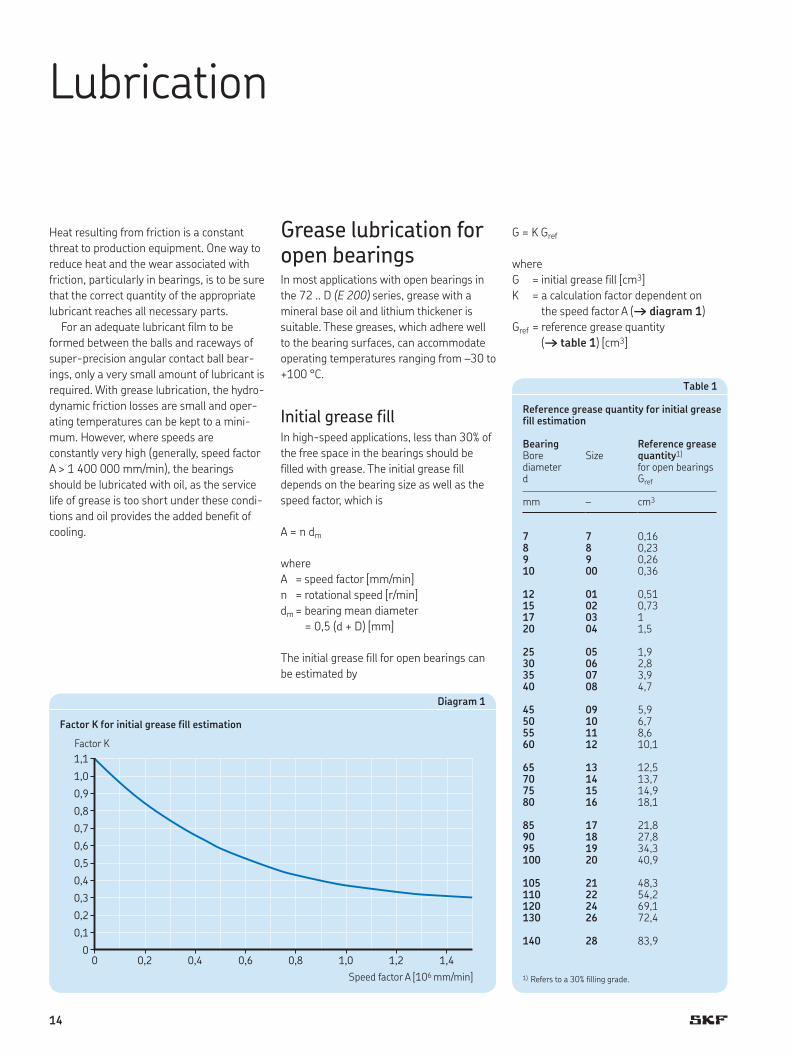
Initial grease fillIn high-speed applications, less than 30% of
the free space in the bearings should be
filled with grease. The initial grease fill
depends on the bearing size as well as the
speed factor, which is
A = n dm
where
A = speed factor [mm/min]
n = rotational speed [r/min]
dm = bearing mean diameter
= 0,5 (d + D) [mm]
The initial grease fill for open bearings can
be estimated by
G = K Gref
where
G = initial grease fill [cm3]
K = a calculation factor dependent on
the speed factor A († diagram 1)
Gref = reference grease quantity
(† table 1) [cm3]
1,1
1,0
0,9
0,8
0,7
0,6
0,5
0,4
0,3
0,2
0,1
00 0,2 0,4 0,6 0,8 1,0 1,2 1,4
Speed factor A [106 mm/min]
Factor K
Diagram 1
Factor K for initial grease fill estimation
1) Refers to a 30% filling grade.
Table 1
Reference grease quantity for initial grease fill estimation
Bearing Reference grease quantity1)Bore Size
diameter for open bearingsd Gref
mm – cm3
7 7 0,168 8 0,239 9 0,2610 00 0,36
12 01 0,5115 02 0,7317 03 120 04 1,5
25 05 1,930 06 2,835 07 3,940 08 4,7
45 09 5,950 10 6,755 11 8,660 12 10,1
65 13 12,570 14 13,775 15 14,980 16 18,1
85 17 21,890 18 27,895 19 34,3100 20 40,9
105 21 48,3110 22 54,2120 24 69,1130 26 72,4
140 28 83,9
14

Sealed bearings
Sealed bearings in the S72 .. D (E 200 /S)
series are filled with a high-grade, low viscos-
ity grease that fills approximately 15% of the
free space in the bearing. The bearings are
relubrication-free under normal operating
conditions. The grease is characterized by:
• high-speed capability (speed factor A up
to 1 200 000 mm/min)
• excellent ageing resistance
• very good rust inhibiting properties
The technical specifications of the grease
are provided in table 2.
Running-in of open and sealed, grease lubricated bearings
A grease lubricated super-precision bearing
will initially run with a relatively high fric-
tional moment. If the bearing is run at high
speed without a running-in period, the tem-
perature rise can be considerable. The rela-
tively high frictional moment is due to the
churning of the grease and it takes time for
the excess grease to work its way out of the
contact zone. For open bearings, this time
period can be minimized by applying a small
quantity of grease distributed evenly on
both sides of the bearing during the assem-
bly stage. Spacers between two adjacent
bearings are also beneficial († Adjusting
preload with spacer rings, page 22).
The time required to stabilize the operat-
ing temperature depends on a number of
factors – the type of grease, the initial grease
fill, how the grease is applied to the bear-
ings, and the running-in procedure
(† diagram 2, page 16).
Super-precision bearings can typically
operate with a minimum quantity of lubri-
cant when properly run-in, enabling the
lowest frictional moment and temperature
to be achieved. Grease that collects on each
side of the bearing acts as a reservoir, ena-
bling oil to bleed into the raceway to provide
effective lubrication for a long time.
Table 2
Technical specifications of the grease in sealed bearings
Properties Grease specification
Thickener Special lithium soap
Base oil type Ester/PAO
NLGI consistency class 2
Temperature range[°C] –40 to +120[°F] –40 to +250
Kinematic viscosity [mm2/s]at 40 °C 25at 100 °C 6
15
B

Running-in can be done in several ways.
Wherever possible and regardless of the
procedure chosen, running-in should
involve operating the bearing in both a
clockwise and anticlockwise direction. For
additional information about running-in
procedures, refer to the SKF Interactive
Engineering Catalogue available online at
www.skf.com.
Diagram 2
Graphic representation of a running-in procedure
Time [h]
Temperature [°C] Speed [r/min]
60
20 0
Operating speed of the system
Absolute temperature limit
Operating temperatureSpeed
10–15 min. forstabilized temperature
† Stage 1 † Stage 2 † Stage 3 † Stage 4 † Stage 5
Oil lubrication for open bearingsOil lubrication is recommended for open
bearings in the 72 .. D (E 200) series in
applications where very high speeds (gener-
ally, speed factor A > 1 400 000 mm/min)
preclude the use of grease as a lubricant.
Oil-air lubrication methodIn some precision applications, the high
operational speeds and requisite low oper-
ating temperatures generally require an oil-
air lubrication system. With the oil-air
method, also called the oil-spot method,
accurately metered quantities of oil are
directed at each individual bearing by com-
pressed air. For bearings used in sets, each
bearing is supplied by a separate oil injector.
Most designs include special spacers that
incorporate the oil nozzles.
Guidelines for the quantity of oil to be
supplied to each bearing for very high speed
operation can be obtained from
Q = 1,3 dm
where
Q = oil flow rate [mm3/h]
dm = bearing mean diameter
= 0,5 (d + D) [mm]
The calculated oil flow rate should be veri-
fied during operation and adjusted, depend-
ing on the resulting temperatures.
16

Oil is supplied to the feed lines at given
intervals by a metering unit. The oil coats
the inside surface of the feed lines and
“creeps” toward the nozzles († fig. 1),
where it is delivered to the bearings. The oil
nozzles should be positioned correctly
(† table 3) to make sure that the oil is
introduced into the contact area between
the balls and raceways and to avoid interfer-
ence with the cage.
High quality lubricating oils without EP
additives are generally recommended for
super-precision angular contact ball bear-
ings. Oils with a viscosity of 40 to
100 mm2/s at 40 °C are typically used. A fil-
ter that prevents particles > 5 µm from
reaching the bearings should also be
incorporated.
Table 3
Oil nozzle position for oil-air lubrication
Bearing Oil nozzle Bore Size positiondiameterd dn
mm – mm
7 7 13,68 8 14,39 9 16,310 00 18,3
12 01 2015 02 2317 03 25,920 04 31,1
25 05 36,130 06 42,735 07 49,740 08 56,2
45 09 60,650 10 65,655 11 72,660 12 80,1
65 13 86,670 14 91,675 15 96,680 16 103,4
85 17 111,590 18 117,595 19 124,4100 20 131,4
105 21 138,4110 22 145,9120 24 158,2130 26 170,7
140 28 184,8
dnd
Fig. 1
Mixing valve
Oil + air line
0,5 to 10 m Helical coil
Nozzle
Oil jet lubrication methodFor very high speed operation, a sufficient
but not excessive amount of oil should be
supplied to the bearing to provide adequate
lubrication, without increasing the operating
temperature unnecessarily. One particularly
efficient method of achieving this is the oil
jet method, common in high-speed turbo-
chargers, where a jet of oil under high pres-
sure is directed at the side of the bearing.
The velocity of the oil jet should be suffi-
ciently high (at least 15 m/s) to penetrate
the turbulence surrounding the rotating
bearing. It is important that the oil leaving
the bearing can be discharged from the
arrangement by adequately dimensioned
ducts.
17
B

Bearing data – general
Boundary dimensions
The boundary dimensions of bearings in the
72 .. D (E 200) series are in accordance with
ISO 15:2011, for dimension series 02.
Chamfer dimensions
Minimum values for the chamfer dimensions
in the radial direction (r1, r3) and the axial
direction (r2, r4) are provided in the product
tables. The values for the chamfers on the
inner ring and thrust side of the outer ring
are in accordance with ISO 15:2011. The
values for the non-thrust side of the outer
ring are in accordance with ISO 12044:1995,
where applicable.
The appropriate maximum chamfer limits
are in accordance with ISO 582:1995.
Tolerances
Bearings in the 72 .. D (E 200) series are
manufactured, standard, to P4A tolerance
class. On request, bearings can be supplied
to the higher precision PA9A tolerance class.
The tolerance values are listed as follows:
• P4A (better than ABEC 7) tolerance class
in table 1
• PA9A (better than ABEC 9) tolerance class
in table 2
The tolerance symbols used in these tables
are listed together with their definitions in
table 3, on page 20.
Bearing preloadA single super-precision angular contact ball
bearing does not have any preload. Preload
can only be obtained when one bearing is
placed against another to provide location in
the opposite direction.
Table 1
Class P4A tolerances
Inner ringd ∆dmp ∆ds Vdp Vdmp ∆Bs ∆B1s VBs Kia Sd Sia
over incl. high low high low max max high low high low max max max max
mm µm µm µm µm µm µm µm µm µm µm
2,5 10 0 –4 0 –4 1,5 1 0 –40 0 –250 1,5 1,5 1,5 1,510 18 0 –4 0 –4 1,5 1 0 –80 0 –250 1,5 1,5 1,5 1,518 30 0 –5 0 –5 1,5 1 0 –120 0 –250 1,5 2,5 1,5 2,530 50 0 –6 0 –6 1,5 1 0 –120 0 –250 1,5 2,5 1,5 2,5
50 80 0 –7 0 –7 2 1,5 0 –150 0 –250 1,5 2,5 1,5 2,580 120 0 –8 0 –8 2,5 1,5 0 –200 0 –380 2,5 2,5 2,5 2,5120 150 0 –10 0 –10 6 3 0 –250 0 –380 4 4 4 4
Outer ringD ∆Dmp ∆Ds VDp VDmp ∆Cs, ∆C1s VCs Kea SD Sea
over incl. high low high low max max max max max max
mm µm µm µm µm µm µm µm µm
18 30 0 –5 0 –5 2 1,5 Values are identical to those for the inner ring of the same bearing (∆Bs, ∆B1s)
1,5 1,5 1,5 1,530 50 0 –6 0 –6 2 1,5 1,5 2,5 1,5 2,550 80 0 –7 0 –7 2 1,5 1,5 4 1,5 480 120 0 –8 0 –8 2,5 1,5 2,5 5 2,5 5
120 150 0 –9 0 –9 4 1,5 2,5 5 2,5 5150 180 0 –10 0 –10 6 3 4 6 4 6180 250 0 –11 0 –11 6 4 5 8 5 8
18
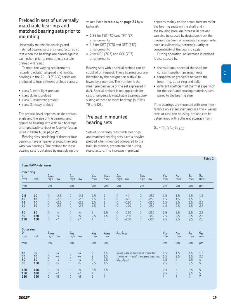
Table 2
Class PA9A tolerances
Inner ringd ∆dmp ∆ds Vdp Vdmp ∆Bs ∆B1s VBs Kia Sd Sia
over incl. high low high low max max high low high low max max max max
mm µm µm µm µm µm µm µm µm µm µm
2,5 10 0 -2,5 0 -2,5 1,5 1 0 -40 0 -250 1,5 1,5 1,5 1,510 18 0 -2,5 0 -2,5 1,5 1 0 -80 0 -250 1,5 1,5 1,5 1,518 30 0 -2,5 0 -2,5 1,5 1 0 -120 0 -250 1,5 2,5 1,5 2,530 50 0 -2,5 0 -2,5 1,5 1 0 -120 0 -250 1,5 2,5 1,5 2,5
50 80 0 -4 0 -4 2 1,5 0 -150 0 -250 1,5 2,5 1,5 2,580 120 0 -5 0 -5 2,5 1,5 0 -200 0 -380 2,5 2,5 2,5 2,5120 150 0 -7 0 -7 4 3 0 -250 0 -380 2,5 2,5 2,5 2,5
Outer ringD ∆Dmp ∆Ds VDp VDmp ∆Cs, ∆C1s VCs Kea SD Sea
over incl. high low high low max max max max max max
mm µm µm µm µm µm µm µm µm
18 30 0 –4 0 –4 2 1,5 Values are identical to those for the inner ring of the same bearing (∆Bs, ∆B1s)
1,5 1,5 1,5 1,530 50 0 –4 0 –4 2 1,5 1,5 2,5 1,5 2,550 80 0 –4 0 –4 2 1,5 1,5 4 1,5 480 120 0 –5 0 –5 2,5 1,5 2,5 5 2,5 5
120 150 0 –5 0 –5 2,5 1,5 2,5 5 2,5 5150 180 0 –7 0 –7 4 3 2,5 5 2,5 5180 250 0 –8 0 –8 5 4 4 7 4 7
Preload in sets of universally matchable bearings and matched bearing sets prior to mounting
Universally matchable bearings and
matched bearing sets are manufactured so
that when the bearings are placed against
each other, prior to mounting, a certain
preload will result.
To meet the varying requirements
regarding rotational speed and rigidity,
bearings in the 72 .. D (E 200) series are
produced to four different preload classes:
• class A, extra light preload
• class B, light preload
• class C, moderate preload
• class D, heavy preload
The preload level depends on the contact
angle and the size of the bearing, and
applies to bearing sets with two bearings
arranged back-to-back or face-to-face as
listed in table 4, on page 21.
Bearing sets consisting of three or four
bearings have a heavier preload than sets
with two bearings. The preload for these
bearing sets is obtained by multiplying the
values listed in table 4, on page 21 by a
factor of:
• 1,35 for TBT (TD) and TFT (TF)
arrangements
• 1,6 for QBT (3TD) and QFT (3TF)
arrangements
• 2 for QBC (TDT) and QFC (TFT)
arrangements
Bearing sets with a special preload can be
supplied on request. These bearing sets are
identified by the designation suffix G fol-
lowed by a number. The number is the
mean preload value of the set expressed in
daN. Special preload is not applicable for
sets of universally matchable bearings con-
sisting of three or more bearings (suffixes
TG and QG).
Preload in mounted bearing sets
Sets of universally matchable bearings
and matched bearing sets have a heavier
preload when mounted compared to the
built-in preload, predetermined during
manufacture. The increase in preload
depends mainly on the actual tolerances for
the bearing seats on the shaft and in
the housing bore. An increase in preload
can also be caused by deviations from the
geometrical form of associated components
such as cylindricity, perpendicularity or
concentricity of the bearing seats.
During operation, an increase in preload
is also caused by:
• the rotational speed of the shaft for
constant position arrangements
• temperature gradients between the
inner ring, outer ring and balls
• different coefficient of thermal expansion
for the shaft and housing materials com-
pared to the bearing steel
If the bearings are mounted with zero inter-
ference on a steel shaft and in a thick-walled
steel or cast iron housing, preload can be
determined with sufficient accuracy from
Gm = f f1 f2 fHC GA,B,C,D
C
19

where
Gm = preload in the mounted bearing set
[N]
GA,B,C,D = built-in preload in the bearing set,
prior to mounting († table 4, on
page 21) [N]
f = a bearing factor dependent on the
bearing size († table 5, on
page 21)
f1 = a correction factor dependent on
the contact angle († table 6, on
page 22)
f2 = a correction factor dependent on
the preload class († table 6, on
page 22)
fHC = a correction factor for hybrid
bearings († table 6, on page 22)
Considerably tighter fits may be neces-
sary, for example for very high speed spin-
dles, where centrifugal forces can loosen the
inner ring from its seat on the shaft. These
bearing arrangements must be carefully
evaluated.
Preload with constant forceIn precision, high-speed applications, a con-
stant and uniform preload is important. To
maintain the proper preload, calibrated lin-
ear springs can be used between one bear-
ing outer ring and its housing shoulder
(† fig. 1). With springs, the kinematic
behaviour of the bearing will not influence
preload under normal operating conditions.
Note, however, that a spring-loaded bearing
arrangement has a lower degree of rigidity
Fig. 1
Tolerance symbols
Tolerance symbol
Definition
Bore diameter
d Nominal bore diameter
ds Single bore diameter
dmp Mean bore diameter; arithmetical mean of the largest and smallest single bore diameters in one plane
Dds Deviation of a single bore diameter from the nominal (Dds = ds – d)
Ddmp Deviation of the mean bore diameter from the nominal (Ddmp = dmp – d)
Vdp Bore diameter variation; difference between the largest and smallest single bore diameters in one plane
Vdmp Mean bore diameter variation; difference between the largest and smallest mean bore diameter
Outside diameter
D Nominal outside diameter
Ds Single outside diameter
Dmp Mean outside diameter; arithmetical mean of the largest and smallest single outside diameters in one plane
DDs Deviation of a single outside diameter from the nominal (DDs = Ds – D)
DDmp Deviation of the mean outside diameter from the nominal (DDmp = Dmp – D)
VDp Outside diameter variation; difference between the largest and smallest single outside diameters in one plane
VDmp Mean outside diameter variation; difference between the largest and smallest mean outside diameter
Table 3
Tolerance symbol
Definition
Width
B, C Nominal width of inner ring and outer ring, respectively
Bs, Cs Single width of inner ring and outer ring, respectively
B1s, C1s Single width of inner ring and outer ring, respectively, of a bearing belonging to a matched set
DBs, DCs Deviation of single inner ring width or single outer ring width from the nominal (DBs = Bs – B; DCs = Cs – C)
DB1s, DC1s Deviation of single inner ring width or single outer ring width of a bearing belonging to a matched set from the nominal (not valid for universally matchable bearings) (DB1s = B1s – B; DC1s = C1s – C)
VBs, VCs Ring width variation; difference between the largest and smallest single widths of inner ring and of outer ring, respectively
Running accuracy
Kia, Kea Radial runout of inner ring and outer ring, respectively, of assembled bearing
Sd Side face runout with reference to bore (of inner ring)
SD Outside inclination variation; variation in inclination of outside cylindrical surface to outer ring side face
Sia, Sea Axial runout of inner ring and outer ring, respectively, of assembled bearing
than an arrangement using axial displace-
ment to set the preload.
20

Table 4
Axial preload of universally matchable bearings and matched bearing pairs, prior to mounting, arranged back-to-back or face-to-face
Bearing Axial preloadBore Size of bearings in the series1)
diameter 72 CD (E 200 CE1) 72 ACD (E 200 CE3)72 CD/HC (E 200 /NS CE1) 72 ACD/HC (E 200 /NS CE3)for preload class for preload class
d A B C D A B C D
mm – N
7 7 12 24 48 96 18 36 72 1448 8 14 28 56 112 22 44 88 1769 9 15 30 60 120 25 50 100 20010 00 17 34 68 136 27 54 108 216
12 01 22 44 88 176 35 70 140 28015 02 30 60 120 240 45 90 180 36017 03 35 70 140 280 60 120 240 48020 04 45 90 180 360 70 140 280 560
25 05 50 100 200 400 80 160 320 64030 06 90 180 360 720 150 300 600 1 20035 07 120 240 480 960 190 380 760 1 52040 08 125 250 500 1 000 200 400 800 1 600
45 09 160 320 640 1 280 260 520 1 040 2 08050 10 170 340 680 1 360 265 530 1 060 2 12055 11 210 420 840 1 680 330 660 1 320 2 64060 12 215 430 860 1 720 350 700 1 400 2 800
65 13 250 500 1 000 2 000 400 800 1 600 3 20070 14 260 520 1 040 2 080 420 840 1 680 3 36075 15 270 540 1 080 2 160 430 860 1 720 3 44080 16 320 640 1 280 2 560 520 1 040 2 080 4 160
85 17 370 740 1 480 2 960 600 1 200 2 400 4 80090 18 480 960 1 920 3 840 750 1 500 3 000 6 00095 19 520 1 040 2 080 4 160 850 1 700 3 400 6 800100 20 590 1 180 2 360 4 720 950 1 900 3 800 7 600
105 21 650 1 300 2 600 5 200 1 000 2 000 4 000 8 000110 22 670 1 340 2 680 5 360 1 050 2 100 4 200 8 400120 24 750 1 500 3 000 6 000 1 200 2 400 4 800 9 600130 26 810 1 620 3 240 6 480 1 300 2 600 5 200 10 400
140 28 850 1 700 3 400 6 800 1 350 2 700 5 400 10 800
1) Data is also applicable to sealed bearings.
Table 5
Bearing factor f for calculating the preload in mounted bearing sets
Bearing Bearing factor f1) Bore
diameterSize
d
mm – –
7 7 1,028 8 1,029 9 1,0210 00 1,02
12 01 1,0215 02 1,0317 03 1,0320 04 1,03
25 05 1,0330 06 1,0535 07 1,0540 08 1,05
45 09 1,0750 10 1,0855 11 1,0860 12 1,07
65 13 1,0770 14 1,0875 15 1,0880 16 1,09
85 17 1,0890 18 1,0995 19 1,09100 20 1,09
105 21 1,08110 22 1,08120 24 1,08130 26 1,09
140 28 1,09
1) Data is also applicable to sealed bearings.
C
21

Preload by axial displacementRigidity and precise axial guidance are crit-
ical parameters in bearing arrangements,
especially when alternating axial forces
occur. In these cases, the preload in the
bearings is usually obtained by adjusting the
bearing rings relative to each other in the
axial direction. This preload method offers
significant benefits in terms of system rigid-
ity. However, depending on the contact angle
and ball material, preload increases consid-
erably with rotational speed.
Universally matchable bearings and
matched bearing sets are manufactured so
that when mounted properly, they will attain
their predetermined axial displacement and
consequently the proper preload. With sin-
gle bearings, precision-matched spacer
rings must be used.
Adjusting preload with spacer rings
By placing precision-matched spacer rings
between two bearings, it is possible to
increase or decrease preload. Precision-
matched spacer rings can also be used to:
• increase system rigidity
• create a sufficiently large grease reservoir
between two bearings
• create a space for oil-air lubrication
nozzles
It is possible to adjust preload in a bearing
set by grinding the side face of the inner or
outer spacer ring. Table 7 provides informa-
tion about which of the equal-width spacer
ring side faces must be ground and what
effect it will have. Guideline values for the
requisite overall width reduction of the
spacer rings are listed in table 8.
To achieve maximum bearing perform-
ance, the spacer rings must not deform
under load. They should be made of high-
grade steel that can be hardened to between
45 and 60 HRC. Particular importance must
be given to the plane parallelism of the side
face surfaces, where the permissible shape
deviation must not exceed 1 to 2 µm.
Effect of rotational speed on preload
Using strain gauges, SKF has determined
that there is a marked increase in preload at
very high speeds. This is mainly attributable
to the heavy centrifugal forces on the balls
causing them to change their position within
the bearing. When compared to an all-steel
bearing, a hybrid bearing can attain much
higher rotational speeds without significant-
ly increasing preload. This is due to the lower
mass of the balls.
Bearing axial stiffness
Axial stiffness depends on the deformation
of the bearing under load and can be
expressed as the ratio of the load to bearing
resilience. However, since there is not a
direct linear relation between bearing resili-
ence and load, constant values for axial stiff-
ness cannot be quoted. Exact values of axial
stiffness, for bearings in the 72 .. D (E 200)
series, for a given preload can be calculated
using advanced computer methods, but
guideline values are listed in table 9, on
page 24. These values apply to mounted
bearing sets under static conditions with
1) Data is also applicable to sealed bearings.
Table 6
Correction factors for calculating the preload in mounted bearing sets
Bearing series1) Correction factorsf1 f2 fHC
for preload class A B C D
72 CD (E 200 CE1) 1 1 1,01 1,03 1,05 1
72 ACD (E 200 CE3) 0,99 1 1,01 1,02 1,05 1
72 CD/HC (E 200 /NS CE1) 1 1 1,01 1,03 1,06 1,01
72 ACD/HC (E 200 /NS CE3) 0,99 1 1,01 1,03 1,06 1,01
Table 7
Guidelines for spacer ring modification
Preload change of a bearing set Width reduction Requisite spacer ringValue between bearings arranged
back-to-back face-to-face
Increasing the preloadfrom A to B a inner outerfrom B to C b inner outerfrom C to D c inner outerfrom A to C a + b inner outerfrom A to D a + b + c inner outer
Decreasing the preloadfrom B to A a outer innerfrom C to B b outer innerfrom D to C c outer innerfrom C to A a + b outer innerfrom D to A a + b + c outer inner
two all-steel bearings arranged back-to-
back or face-to-face and subjected to
moderate loads.
Bearing sets comprising three or four
bearings can provide a higher degree of axial
stiffness than sets with two bearings. The
axial stiffness for these sets can be calcu-
lated by multiplying the values listed in
table 9, on page 24, by a factor dependent
on the bearing arrangement:
• 1,45 for TBT (TD) and TFT (TF)
arrangements
• 1,8 for QBT (3TD) and QFT (3TF)
arrangements
• 2 for QBC (TDT) and QFC (TFT)
arrangements
For hybrid bearings, the axial stiffness can
be calculated in the same way as for all-
steel bearings. However, the calculated
value should then be multiplied by a factor
of 1,11 (for all arrangements and preload
classes).
22

Table 8
Guideline values for spacer ring width reduction
Bearing Requisite spacer ring width reductionBore diameter Size for bearings in the series1)
72 CD (E 200 CE1) 72 ACD (E 200 CE3)d a b c a b c
mm – µm
7 7 4 5 8 2 4 68 8 4 6 9 3 4 79 9 4 6 9 3 4 710 00 4 6 9 3 4 7
12 01 5 7 10 3 5 715 02 6 8 12 4 5 817 03 6 9 13 4 6 1020 04 6 10 14 4 6 10
25 05 6 10 14 4 6 1030 06 8 11 16 5 8 1235 07 9 13 19 6 9 1440 08 9 13 19 6 9 14
45 09 10 15 21 7 10 1650 10 10 15 21 7 10 1655 11 11 16 24 7 11 1860 12 11 16 24 7 11 18
65 13 12 18 26 8 13 1970 14 12 18 26 8 13 1975 15 12 18 26 8 13 1980 16 13 19 28 9 14 21
85 17 14 21 30 9 14 2290 18 16 24 37 11 17 2695 19 17 26 38 12 18 28100 20 19 28 40 12 19 30
105 21 19 29 42 13 20 30110 22 19 29 42 13 20 30120 24 21 31 45 14 21 33130 26 21 31 45 14 21 33
140 28 21 31 45 14 21 33
1) Data is also applicable to sealed bearings.
a, b, c
a, b, c a, b, c
a, b, c
Increasing the preload(back-to-back arrangement)
Decreasing the preload(back-to-back arrangement)
Increasing the preload(face-to-face arrangement)
Decreasing the preload(face-to-face arrangement)
C
23

Fitting and clamping of bearing ringsSuper-precision angular contact ball bear-
ings are typically located axially on shafts or
in housings with either precision lock nuts
(† fig. 2) or end caps. These components
require high geometrical precision and good
mechanical strength to provide reliable
locking.
The tightening torque Mt, for precision
lock nuts or end cap bolts, must be sufficient
to prevent relative movement of adjacent
components, maintain the position of the
Fig. 2bearings without deformation, and minimize
material fatigue.
Calculating the tightening torque Mt
It is difficult to accurately calculate the tight-
ening torque Mt for a precision lock nut or
the bolts in an end cap. The following for-
mulas can be used to do the calculations,
but the results should be verified during
operation.
Table 9
Static axial stiffness for bearing pairs arranged back-to-back or face-to-face
Bearing Static axial stiffnessBore diameter
Size of all-steel bearings in the series1)
72 CD (E 200 CE1) 72 ACD (E 200 CE3)for preload class for preload class
d A B C D A B C D
mm – N/µm
7 7 11 15 21 30 27 35 46 618 8 12 15 21 30 28 36 48 639 9 13 17 23 33 32 41 54 7110 00 14 19 26 37 35 45 59 78
12 01 16 22 30 42 41 52 68 9015 02 19 26 35 49 46 60 78 10217 03 21 28 38 53 53 68 89 11820 04 25 33 45 63 61 79 102 135
25 05 29 38 52 72 71 92 119 15830 06 43 59 82 118 105 137 181 24435 07 50 67 94 136 119 154 204 27540 08 53 71 100 143 127 165 218 294
45 09 61 82 115 166 146 190 252 34150 10 65 88 124 178 154 201 266 35955 11 72 98 137 197 172 224 296 39960 12 75 102 142 205 182 238 315 424
65 13 78 106 148 212 189 245 324 43770 14 83 112 156 225 201 261 345 46475 15 87 118 165 237 211 274 361 48780 16 96 130 181 260 257 303 401 540
85 17 102 139 193 278 250 325 429 57890 18 114 154 215 314 273 355 469 63295 19 115 156 217 313 280 365 482 649100 20 122 165 230 331 296 388 509 685
105 21 129 174 243 349 308 399 527 708110 22 135 183 254 364 325 423 557 748120 24 139 188 261 373 338 440 579 777130 26 155 209 291 416 378 491 530 869
140 28 163 220 305 437 397 516 679 911
1) Data is also applicable to sealed bearings.
24

Table 10
Minimum axial clamping force and axial fitting force for precision lock nuts and end caps
Bearing Minimum axial clamping force
Axial fitting forceBore diameter Size
d Fs Fc
mm – N
7 7 490 5508 8 490 6009 9 650 60010 00 850 700
12 01 1 000 70015 02 950 60017 03 1 300 70020 04 2 300 850
25 05 2 400 75030 06 3 400 70035 07 5 500 1 20040 08 6 000 1 200
45 09 7 000 1 20050 10 6 000 1 00055 11 7 500 1 10060 12 11 000 1 300
65 13 13 000 1 30070 14 14 000 1 30075 15 15 000 1 30080 16 17 000 1 900
85 17 19 000 2 50090 18 19 000 2 50095 19 27 000 3 000100 20 27 000 3 100
105 21 31 000 3 300110 22 37 000 3 600120 24 45 000 4 300130 26 48 000 4 500
140 28 59 000 5 000
Table 11
Factor K for calculating the tightening torque
Nominal thread diameter1)
Factor Kforprecision lock nuts end cap bolts
– –
M 4 – 0,8M 5 – 1M 6 – 1,2M 8 – 1,6
M 10 1,4 2M 12 1,6 2,4M 14 1,9 2,7M 15 2 2,9
M 16 2,1 3,1M 17 2,2 –M 20 2,6 –M 25 3,2 –
M 30 3,9 –M 35 4,5 –M 40 5,1 –M 45 5,8 –
M 50 6,4 –M 55 7 –M 60 7,6 –M 65 8,1 –
M 70 9 –M 75 9,6 –M 80 10 –M 85 11 –
M 90 11 –M 95 12 –M 100 12 –M 105 13 –
M 110 14 –M 120 15 –M 130 16 –M 140 17 –
1) Applicable for fine threads only
The axial clamping force for a precision
lock nut or the bolts in an end cap is
Pa = Fs + (NcpFc) + GA,B,C,D
The tightening torque for a precision lock
nut is
Mt = K Pa
= K [Fs + (NcpFc) + GA,B,C,D]
The tightening torque for end cap bolts is
K PaMt = ––––– Nb
K [Fs + (NcpFc) + GA,B,C,D]Mt = –––––––––––––––––––– Nb
where
Mt = tightening torque [Nmm]
Pa = axial clamping force [N]
Fs = minimum axial clamping force
(† table 10) [N]
Fc = axial fitting force († table 10) [N]
GA,B,C,D = built-in bearing preload, prior
to mounting († table 4 on
page 21) [N]
Ncp = the number of preloaded bearings
Nb = the number of end cap bolts
K = a calculation factor dependent on
the thread († table 11)
Load carrying capacity of bearing setsThe values listed in the product tables for
the basic dynamic load rating C, the basic
static load rating C0 and the fatigue load
limit Pu apply to single bearings. For bearing
sets, the values for single bearings should be
multiplied by a calculation factor according to
table 12 on page 27.
C
25

Fig. 3
Equivalent bearing loadsWhen determining the equivalent bearing
load, the preload must be taken into
account. Depending on the operating condi-
tions, the requisite axial component of the
bearing load Fa for a bearing pair arranged
back-to-back or face-to-face can be
approximated using the following equations.
For bearing pairs under radial load and
mounted with an interference fit
Fa = Gm
For bearing pairs under radial load and
preloaded using springs
Fa = GA,B,C,D
For bearing pairs under axial load and
mounted with an interference fit
Fa = Gm + 0,67 Ka for Ka ≤ 3 Gm
Fa = Ka for Ka > 3 Gm
For bearing pairs under axial load and
preloaded using springs
Fa = GA,B,C,D + Ka
where
Fa = axial component of the load [N]
GA,B,C,D = built-in preload of the bearing pair,
prior to mounting († table 4 on
page 21) [N]
Gm = preload in the mounted bearing
pair († Preload in mounted
bearing sets, page 19) [N]
Ka = external axial force acting on a
single bearing [N]
Equivalent dynamic bearing load
For single bearings and bearings paired in
tandem
P = Fr for Fa/Fr ≤ e
P = XFr + YFa for Fa/Fr > e
For bearing pairs, arranged back-to-back or
face-to-face
P = Fr + Y1Fa for Fa/Fr ≤ e
P = XFr + Y2Fa for Fa/Fr > e
where
P = equivalent dynamic load of the bearing
set [kN]
Fr = radial component of the load acting on
the bearing set [kN]
Fa = axial component of the load acting on
the bearing set [kN]
The values for the calculation factors e, X, Y,
Y1 and Y2 depend on the bearing contact
angle and are listed in tables 13 and 14. For
bearings with a 15° contact angle, the fac-
tors also depend on the relationship f0Fa/C0
where f0 is the calculation factor and C0 is
the basic static load rating, both of which are
listed in the product tables.
Equivalent static bearing loadFor single bearings and bearings paired in
tandem
P0 = 0,5 Fr + Y0Fa
For bearing pairs, arranged back-to-back or
face-to-face
P0 = Fr + Y0Fa
where
P0 = equivalent static load of the bearing
set [kN]
Fr = radial component of the load acting
on the bearing set [kN]
Fa = axial component of the load acting
on the bearing set [kN]
If P0 < Fr , P0 = Fr should be used. The values
for the calculation factor Y0 depend on the
bearing contact angle and are listed in
tables 13 and 14.
Attainable speeds
The attainable speeds listed in the product
tables should be regarded as guideline
values. They are valid for single bearings
under light load (P ≤ 0,05 C) that are lightly
preloaded using springs. In addition, good
heat dissipation from the bearing arrange-
ment is a prerequisite. As there is no friction
generated at the seal lip, the attainable
speed of a sealed bearing is equivalent to a
comparably sized open bearing.
The values provided for oil lubrication
apply to the oil-air lubrication method
and should be reduced if other oil lubrication
methods are used. The values provided for
grease lubrication are maximum values
that can be attained with sealed bearings
or open bearings with good lubricating
grease that has a low consistency and low
viscosity. Sealed bearings in the S72 .. D
(E 200 /S) series are designed for high-
speed operation i.e. for a speed factor A
up to 1 200 000 mm/min.
If single bearings are adjusted against
each other with heavier preload or if bearing
sets are used, the attainable speeds listed in
the product tables should be reduced i.e. the
values should be multiplied by a reduction
factor. Values for this reduction factor, which
depend on the bearing arrangement and
preload class, are listed in table 15.
If the rotational speed obtained is not suf-
ficient for the application, precision-matched
spacer rings in the bearing set can be used
to significantly increase the speed capability.
Cages
Depending on their size, bearings in the
72 .. D (E 200) series are fitted, standard,
with a one-piece outer ring shoulder-guided
cage made of one of the following materials:
Standard cages are not identified in the
bearing designation. Bearings that have
a PEEK cage are marked in the product
tables by a footnote.
26

Table 15
Speed reduction factors for bearing sets
Number of bearings
Arrangement Designation suffix Speed reduction factorfor matched sets for preload class
A B C D
2 Back-to-back DB (DD) 0,81 0,75 0,65 0,40Face-to-face DF (FF) 0,77 0,72 0,61 0,36
3 Back-to-back and tandem TBT (TD) 0,7 0,63 0,49 0,25Face-to-face and tandem TFT (TF) 0,63 0,56 0,42 0,17
4 Tandem back-to-back QBC (TDT) 0,64 0,6 0,53 0,32Tandem face-to-face QFC (TFT) 0,62 0,58 0,48 0,27
Note: For spring-loaded tandem sets, designation suffix DT (T), a speed reduction factor of 0,9 should be applied.
• fabric reinforced phenolic resin, which can
withstand temperatures up to 120 °C
• carbon fibre reinforced polyetheretherketone
(PEEK), which can withstand temperatures
up to 150 °C († fig. 3)
Seals
The integral seals in sealed S72 .. D
(E 200 /S) series bearings are designed for a
speed factor A up to 1 200 000 mm/min.
The permissible operating temperature
range of the seals is –25 to +100 °C and up
to 120 °C for brief periods.
Materials
The rings and balls of all-steel bearings in
the 72 .. D (E 200) series are made from
SKF Grade 3 steel, in accordance with ISO
683-17:1999. Balls of hybrid bearings are
made of bearing grade silicon nitride Si3N4.
The integral seals in sealed bearings are
made of an oil-and wear-resistant acrylo-
nitrile-butadiene rubber (NBR) and are
re inforced with sheet steel.
Heat treatment
SKF super-precision bearings undergo a
special heat treatment to achieve a good
balance between hardness and dimensional
stability. The hardness of the rings and rolling
elements of bearings in the 72 .. D (E 200)
series is optimized for wear-resistance and
the rings are heat stabilized to accommodate
temperatures up to 150 °C.
Table 13
Calculation factors for single bearings and bearings paired in tandem
f0Fa/C0 Calculation factors e X Y Y0
For 15° contact angledesignation suffix CD (1)
≤ 0,178 0,38 0,44 1,47 0,460,357 0,4 0,44 1,4 0,460,714 0,43 0,44 1,3 0,461,07 0,46 0,44 1,23 0,46
1,43 0,47 0,44 1,19 0,462,14 0,5 0,44 1,12 0,463,57 0,55 0,44 1,02 0,46≥ 5,35 0,56 0,44 1 0,46
For 25° contact angledesignation suffix ACD (3)
– 0,68 0,41 0,87 0,38
Table 14
Calculation factors for bearing pairs arranged back-to-back or face-to-face
2 f0Fa/C0 Calculation factors e X Y1 Y2 Y0
For 15° contact angledesignation suffix CD (1)
≤ 0,178 0,38 0,72 1,65 2,39 0,920,357 0,4 0,72 1,57 2,28 0,920,714 0,43 0,72 1,46 2,11 0,921,07 0,46 0,72 1,38 2 0,92
1,43 0,47 0,72 1,34 1,93 0,922,14 0,5 0,72 1,26 1,82 0,923,57 0,55 0,72 1,14 1,66 0,92≥ 5,35 0,56 0,72 1,12 1,63 0,92
For 25° contact angledesignation suffix ACD (3)
– 0,68 0,67 0,92 1,41 0,76
Table 12
Calculation factors for load carrying capacities of bearing sets
Number of bearings
Calculation factorfor
C C0 Pu
2 1,62 2 2
3 2,16 3 3
4 2,64 4 4
C
27

Fa
Fig. 5Marking of bearings and bearing setsEach bearing in the 72 .. D (E 200) series
has various identifiers on the external
surfaces of the rings. The position of the
identifiers may differ between open and
sealed bearings. Open bearings are marked
as follows († fig. 4):
1 SKF trademark
2 Complete designation of the bearing
3 Country of manufacture
4 Date of manufacture, coded
5 Deviation of the mean outside diameter,
DDm [µm], and position of the maximum
eccentricity of the outer ring
6 Deviation of the mean bore diameter,
Ddm [µm], and position of the maximum
eccentricity of the inner ring
7 Thrust face mark, punched
8 Serial number (bearing sets only)
9 “V-shaped” marking (matched bearing
sets only)
Fig. 4
1
7
9
4
5
2
6
3
8
“V-shaped” markingA “V-shaped” marking on the outside sur-
face of the outer rings of matched bearing
sets indicates how the bearings should be
mounted to obtain the proper preload in the
set. The marking also indicates how the
bearing set should be mounted in relation to
the axial load. The “V-shaped” marking
should point in the direction in which the
axial load will act on the inner ring
(† fig. 5). In applications where there are
axial loads in both directions, the “V-shaped”
marking should point toward the greater of
the two loads.
28

Fig. 6Packaging
SKF super-precision bearings are distrib-
uted in new SKF illustrated boxes († fig. 6).
An instruction sheet, with information about
mounting bearing sets, is supplied in each
box.
Designation system
The designations for SKF bearings in the
72 .. D (E 200) series are provided in
table 16 on page 30 together with their
definitions.
C
29

Designation system for SKF super-precision angular contact ball bearings in the 72 .. D (E 200) series
Single bearing: 7214 ACDGA/HCP4A
72 14 ACD GA / HC P4A
Variant prefix Series Size
Contact angle
and design
Execution and preload
(single bearing)
Ball material
Tolerance class
Arrangement Preload
Matched bearing set: S7220 CD/PA9AQBCD
S 72 20 CD / PA9A QBC D
Sealing – Open bearing (no designation prefix)S Sealed bearing
Bearing series72 In accordance with ISO dimension series 02
Bearing size 7 7 mm bore diameter8 8 mm bore diameter9 9 mm bore diameter00 10 mm bore diameter01 12 mm bore diameter02 15 mm bore diameter03 17 mm bore diameter04 (x5) 20 mm bore diameterto28 (x5) 140 mm bore diameter
Contact angle and internal design CD 15° contact angle, high-capacity basic designACD 25° contact angle, high-capacity basic design
Single bearing – execution and preload1) – Single bearing (no designation suffix)GA Single, universally matchable, for extra light preload GB Single, universally matchable, for light preload GC Single, universally matchable, for moderate preloadGD Single, universally matchable, for heavy preload
Cage – Fabric reinforced phenolic resin or carbon fibre reinforced PEEK, outer ring centred (no designation suffix)
Ball material – Carbon chromium steel (no designation suffix)HC Bearing grade silicon nitride Si3N4 (hybrid bearings)
Tolerance class P4A Dimensional accuracy in accordance with ISO tolerance class 4, running accuracy better than ISO tolerance class 4PA9A Dimensional and running accuracy better than ABMA tolerance class ABEC 9
Bearing set – arrangement DB Two bearings arranged back-to-back <>DF Two bearings arranged face-to-face ><DT Two bearings arranged in tandem <<DG Two bearings for universal matchingTBT Three bearings arranged back-to-back and tandem <>>TFT Three bearings arranged face-to-face and tandem ><<TT Three bearings arranged in tandem <<<TG Three bearings for universal matchingQBC Four bearings arranged tandem back-to-back <<>>QFC Four bearings arranged tandem face-to-face >><<QBT Four bearings arranged back-to-back and tandem <>>>QFT Four bearings arranged face-to-face and tandem ><<<QT Four bearings arranged in tandem <<<<QG Four bearings for universal matching
Bearing set – preload1) A Extra light preloadB Light preloadC Moderate preloadD Heavy preload G… Special preload, expressed in daN e.g. G240
1) Equivalence between preload classes of SKF and SNFA bearings has to be evaluated in each case as it depends on the bearing size and arrangement. For additional information, contact the SKF application engineering service.
30
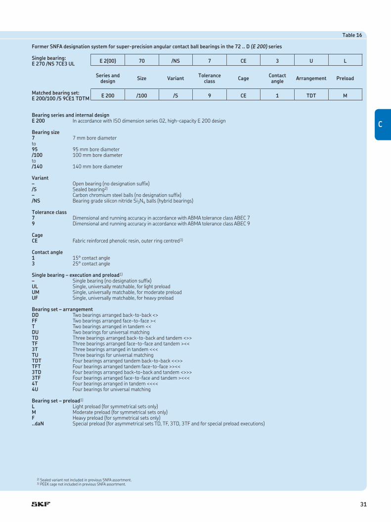
Table 16
Former SNFA designation system for super-precision angular contact ball bearings in the 72 .. D (E 200) series
Single bearing:E 270 /NS 7CE3 UL
E 2(00) 70 /NS 7 CE 3 U L
Series and design
Size VariantTolerance
classCage
Contact angle
Arrangement Preload
Matched bearing set:E 200/100 /S 9CE1 TDTM
E 200 /100 /S 9 CE 1 TDT M
Bearing series and internal designE 200 In accordance with ISO dimension series 02, high-capacity E 200 design
Bearing size7 7 mm bore diameterto95 95 mm bore diameter/100 100 mm bore diameterto/140 140 mm bore diameter
Variant– Open bearing (no designation suffix)/S Sealed bearing2)
– Carbon chromium steel balls (no designation suffix)/NS Bearing grade silicon nitride Si3N4 balls (hybrid bearings)
Tolerance class7 Dimensional and running accuracy in accordance with ABMA tolerance class ABEC 79 Dimensional and running accuracy in accordance with ABMA tolerance class ABEC 9
CageCE Fabric reinforced phenolic resin, outer ring centred3)
Contact angle1 15° contact angle3 25° contact angle
Single bearing – execution and preload1)
– Single bearing (no designation suffix)UL Single, universally matchable, for light preload UM Single, universally matchable, for moderate preloadUF Single, universally matchable, for heavy preload
Bearing set – arrangementDD Two bearings arranged back-to-back <>FF Two bearings arranged face-to-face ><T Two bearings arranged in tandem <<DU Two bearings for universal matchingTD Three bearings arranged back-to-back and tandem <>>TF Three bearings arranged face-to-face and tandem ><<3T Three bearings arranged in tandem <<<TU Three bearings for universal matchingTDT Four bearings arranged tandem back-to-back <<>>TFT Four bearings arranged tandem face-to-face >><<3TD Four bearings arranged back-to-back and tandem <>>>3TF Four bearings arranged face-to-face and tandem ><<<4T Four bearings arranged in tandem <<<<4U Four bearings for universal matching
Bearing set – preload1)
L Light preload (for symmetrical sets only)M Moderate preload (for symmetrical sets only)F Heavy preload (for symmetrical sets only)..daN Special preload (for asymmetrical sets TD, TF, 3TD, 3TF and for special preload executions)
2) Sealed variant not included in previous SNFA assortment.3) PEEK cage not included in previous SNFA assortment.
C
31

d1
r1
r1
r3
r1
r4r2
r2r2
D1D d
a
B
1) Indicates a PEEK cage as standard, otherwise the cage is phenolic resin.
Sealed variantOpen variant
7 22 7 2,96 1,16 0,049 8,4 80 000 120 000 0,013 727 CD/P4A E 207 7CE122 7 2,96 1,16 0,049 8,4 95 000 150 000 0,012 727 CD/HCP4A E 207 /NS 7CE122 7 2,91 1,12 0,048 – 70 000 110 000 0,013 727 ACD/P4A E 207 7CE322 7 2,91 1,12 0,048 – 85 000 130 000 0,012 727 ACD/HCP4A E 207 /NS 7CE3
8 24 8 3,71 1,37 0,057 7,9 70 000 110 000 0,017 728 CD/P4A E 208 7CE124 8 3,71 1,37 0,057 7,9 85 000 130 000 0,015 728 CD/HCP4A E 208 /NS 7CE124 8 3,58 1,34 0,057 – 67 000 100 000 0,017 728 ACD/P4A E 208 7CE324 8 3,58 1,34 0,057 – 75 000 120 000 0,015 728 ACD/HCP4A E 208 /NS 7CE3
9 26 8 4,10 1,66 0,071 8,3 67 000 100 000 0,020 729 CD/P4A E 209 7CE126 8 4,10 1,66 0,071 8,3 80 000 120 000 0,018 729 CD/HCP4A E 209 /NS 7CE126 8 3,97 1,6 0,067 – 60 000 90 000 0,020 729 ACD/P4A E 209 7CE326 8 3,97 1,6 0,067 – 70 000 110 000 0,018 729 ACD/HCP4A E 209 /NS 7CE3
10 30 9 4,49 1,93 0,08 8,8 60 000 90 000 0,032 7200 CD/P4A E 210 7CE130 9 4,49 1,93 0,08 8,8 60 000 – 0,032 S7200 CD/P4A E 210 /S 7CE130 9 4,49 1,93 0,08 8,8 70 000 100 000 0,029 7200 CD/HCP4A E 210 /NS 7CE130 9 4,49 1,93 0,08 8,8 70 000 – 0,029 S7200 CD/HCP4A E 210 /S/NS 7CE130 9 4,36 1,86 0,078 – 53 000 80 000 0,032 7200 ACD/P4A E 210 7CE330 9 4,36 1,86 0,078 – 53 000 – 0,032 S7200 ACD/P4A E 210 /S 7CE330 9 4,36 1,86 0,078 – 63 000 95 000 0,029 7200 ACD/HCP4A E 210 /NS 7CE330 9 4,36 1,86 0,078 – 63 000 – 0,029 S7200 ACD/HCP4A E 210 /S/NS 7CE3
12 32 10 5,85 2,55 0,108 8,5 53 000 80 000 0,037 7201 CD/P4A1) E 212 7CE132 10 5,85 2,55 0,108 8,5 53 000 – 0,038 S7201 CD/P4A1) E 212 /S 7CE132 10 5,85 2,55 0,108 8,5 67 000 95 000 0,033 7201 CD/HCP4A1) E 212 /NS 7CE132 10 5,85 2,55 0,108 8,5 67 000 – 0,034 S7201 CD/HCP4A1) E 212 /S/NS 7CE132 10 5,72 2,45 0,104 – 48 000 70 000 0,037 7201 ACD/P4A1) E 212 7CE332 10 5,72 2,45 0,104 – 48 000 – 0,038 S7201 ACD/P4A1) E 212 /S 7CE332 10 5,72 2,45 0,104 – 56 000 85 000 0,033 7201 ACD/HCP4A1) E 212 /NS 7CE332 10 5,72 2,45 0,104 – 56 000 – 0,034 S7201 ACD/HCP4A1) E 212 /S/NS 7CE3
15 35 11 7,41 3,35 0,14 8,5 48 000 70 000 0,043 7202 CD/P4A1) E 215 7CE135 11 7,41 3,35 0,14 8,5 48 000 – 0,044 S7202 CD/P4A1) E 215 /S 7CE135 11 7,41 3,35 0,14 8,5 60 000 85 000 0,037 7202 CD/HCP4A1) E 215 /NS 7CE135 11 7,41 3,35 0,14 8,5 60 000 – 0,038 S7202 CD/HCP4A1) E 215 /S/NS 7CE135 11 7,15 3,2 0,134 – 43 000 63 000 0,043 7202 ACD/P4A1) E 215 7CE335 11 7,15 3,2 0,134 – 43 000 – 0,044 S7202 ACD/P4A1) E 215 /S 7CE335 11 7,15 3,2 0,134 – 50 000 75 000 0,037 7202 ACD/HCP4A1) E 215 /NS 7CE335 11 7,15 3,2 0,134 – 50 000 – 0,038 S7202 ACD/HCP4A1) E 215 /S/NS 7CE3
Super-precision angular contact ball bearings
d 7 – 15 mm
Principal dimensions
Basic load ratings Fatigue load limit
Calculation factor
Attainable speeds Mass Designationsdynamic static when lubricating with SKF SNFA
grease oil-aird D B C C0 Pu f0
mm kN kN – r/min kg –
32

rb
ra
daDa
ra
ra
db Db
7 12,6 17,4 0,3 0,2 6 9,4 19,6 20,2 0,3 0,212,6 17,4 0,3 0,2 6 9,4 19,6 20,2 0,3 0,212,6 17,4 0,3 0,2 7 9,4 19,6 20,2 0,3 0,212,6 17,4 0,3 0,2 7 9,4 19,6 20,2 0,3 0,2
8 13,1 18,9 0,3 0,2 6 10,4 21,6 22,2 0,3 0,213,1 18,9 0,3 0,2 6 10,4 21,6 22,2 0,3 0,213,1 18,9 0,3 0,2 8 10,4 21,6 22,2 0,3 0,213,1 18,9 0,3 0,2 8 10,4 21,6 22,2 0,3 0,2
9 15,1 20,9 0,3 0,2 6 11,4 23,6 24,2 0,3 0,215,1 20,9 0,3 0,2 6 11,4 23,6 24,2 0,3 0,215,1 20,9 0,3 0,2 8 11,4 23,6 24,2 0,3 0,215,1 20,9 0,3 0,2 8 11,4 23,6 24,2 0,3 0,2
10 17,3 23,1 0,6 0,3 7 14,2 25,8 27,6 0,6 0,317,3 24,3 0,6 0,3 7 14,2 25,8 27,6 0,6 0,317,3 23,1 0,6 0,3 7 14,2 25,8 27,6 0,6 0,317,3 24,3 0,6 0,3 7 14,2 25,8 27,6 0,6 0,317,3 23,1 0,6 0,3 7 14,2 25,8 27,6 0,6 0,317,3 24,3 0,6 0,3 9 14,2 25,8 27,6 0,6 0,317,3 23,1 0,6 0,3 9 14,2 25,8 27,6 0,6 0,317,3 24,3 0,6 0,3 9 14,2 25,8 27,6 0,6 0,3
12 18,6 25,4 0,6 0,3 8 16,2 27,8 29,6 0,6 0,318,6 26,6 0,6 0,3 8 16,2 27,8 29,6 0,6 0,318,6 25,4 0,6 0,3 8 16,2 27,8 29,6 0,6 0,318,6 26,6 0,6 0,3 8 16,2 27,8 29,6 0,6 0,318,6 25,4 0,6 0,3 10 16,2 27,8 29,6 0,6 0,318,6 26,6 0,6 0,3 10 16,2 27,8 29,6 0,6 0,318,6 25,4 0,6 0,3 10 16,2 27,8 29,6 0,6 0,318,6 26,6 0,6 0,3 10 16,2 27,8 29,6 0,6 0,3
15 21,4 29,1 0,6 0,3 9 19,2 30,8 32,6 0,6 0,321,4 30,7 0,6 0,3 9 19,2 30,8 32,6 0,6 0,321,4 29,1 0,6 0,3 9 19,2 30,8 32,6 0,6 0,321,4 30,7 0,6 0,3 9 19,2 30,8 32,6 0,6 0,321,4 29,1 0,6 0,3 12 19,2 30,8 32,6 0,6 0,321,4 30,7 0,6 0,3 12 19,2 30,8 32,6 0,6 0,321,4 29,1 0,6 0,3 12 19,2 30,8 32,6 0,6 0,321,4 30,7 0,6 0,3 12 19,2 30,8 32,6 0,6 0,3
Dimensions Abutment and fillet dimensions
d d1 D1 r1,2 r3,4 a da,db Da Db ra rb~ ~ min min min max max max max
mm mm
C
33

Super-precision angular contact ball bearings
d 17 – 35 mm
17 40 12 9,23 4,15 0,176 8,5 43 000 63 000 0,063 7203 CD/P4A1) E 217 7CE140 12 9,23 4,15 0,176 8,5 43 000 – 0,065 S7203 CD/P4A1) E 217 /S 7CE140 12 9,23 4,15 0,176 8,5 53 000 75 000 0,054 7203 CD/HCP4A1) E 217 /NS 7CE140 12 9,23 4,15 0,176 8,5 53 000 – 0,056 S7203 CD/HCP4A1) E 217 /S/NS 7CE140 12 8,84 4 0,17 – 38 000 56 000 0,063 7203 ACD/P4A1) E 217 7CE340 12 8,84 4 0,17 – 38 000 – 0,065 S7203 ACD/P4A1) E 217 /S 7CE340 12 8,84 4 0,17 – 45 000 67 000 0,054 7203 ACD/HCP4A1) E 217 /NS 7CE340 12 8,84 4 0,17 – 45 000 – 0,056 S7203 ACD/HCP4A1) E 217 /S/NS 7CE3
20 47 14 11,9 5,85 0,245 8,7 36 000 53 000 0,10 7204 CD/P4A1) E 220 7CE147 14 11,9 5,85 0,245 8,7 36 000 – 0,11 S7204 CD/P4A1) E 220 /S 7CE147 14 11,9 5,85 0,245 8,7 43 000 60 000 0,090 7204 CD/HCP4A1) E 220 /NS 7CE147 14 11,9 5,85 0,245 8,7 43 000 – 0,092 S7204 CD/HCP4A1) E 220 /S/NS 7CE147 14 11,4 5,6 0,236 – 32 000 48 000 0,10 7204 ACD/P4A1) E 220 7CE347 14 11,4 5,6 0,236 – 32 000 – 0,11 S7204 ACD/P4A1) E 220 /S 7CE347 14 11,4 5,6 0,236 – 38 000 56000 0,090 7204 ACD/HCP4A1) E 220 /NS 7CE347 14 11,4 5,6 0,236 – 38 000 – 0,092 S7204 ACD/HCP4A1) E 220 /S/NS 7CE3
25 52 15 13,5 7,2 0,305 9,1 30 000 45 000 0,13 7205 CD/P4A1) E 225 7CE152 15 13,5 7,2 0,305 9,1 30 000 – 0,13 S7205 CD/P4A1) E 225 /S 7CE152 15 13,5 7,2 0,305 9,1 38 000 53 000 0,11 7205 CD/HCP4A1) E 225 /NS 7CE152 15 13,5 7,2 0,305 9,1 38 000 – 0,11 S7205 CD/HCP4A1) E 225 /S/NS 7CE152 15 13 6,95 0,29 – 26 000 40 000 0,13 7205 ACD/P4A1) E 225 7CE352 15 13 6,95 0,29 – 26 000 – 0,13 S7205 ACD/P4A1) E 225 /S 7 CE352 15 13 6,95 0,29 – 32 000 48 000 0,11 7205 ACD/HCP4A1) E 225 /NS 7CE352 15 13 6,95 0,29 – 32 000 – 0,11 S7205 ACD/HCP4A1) E 225 /S/NS 7CE3
30 62 16 24,2 16 0,67 14 24 000 38 000 0,20 7206 CD/P4A1) E 230 7CE162 16 24,2 16 0,67 14 24 000 – 0,20 S7206 CD/P4A1) E 230 /S 7CE162 16 24,2 16 0,67 14 32 000 45 000 0,17 7206 CD/HCP4A1) E 230 /NS 7CE162 16 24,2 16 0,67 14 32 000 – 0,17 S7206 CD/HCP4A1) E 230 /S/NS 7CE162 16 23,4 15,3 0,64 – 20 000 34 000 0,20 7206 ACD/P4A1) E 230 7CE362 16 23,4 15,3 0,64 – 20 000 – 0,20 S7206 ACD/P4A1) E 230 /S 7CE362 16 23,4 15,3 0,64 – 26 000 40 000 0,17 7206 ACD/HCP4A1) E 230 /NS 7CE362 16 23,4 15,3 0,64 – 26 000 – 0,17 S7206 ACD/HCP4A1) E 230 /S/NS 7CE3
35 72 17 31,9 21,6 0,915 13,9 20 000 34 000 0,29 7207 CD/P4A1) E 235 7CE172 17 31,9 21,6 0,915 13,9 20 000 – 0,29 S7207 CD/P4A1) E 235 /S 7CE172 17 31,9 21,6 0,915 13,9 26 000 38 000 0,24 7207 CD/HCP4A1) E 235 /NS 7CE172 17 31,9 21,6 0,915 13,9 26 000 – 0,25 S7207 CD/HCP4A1) E 235 /S/NS 7CE172 17 30,7 20,8 0,88 – 18 000 30 000 0,29 7207 ACD/P4A1) E 235 7CE372 17 30,7 20,8 0,88 – 18 000 – 0,29 S7207 ACD/P4A1) E 235 /S 7CE372 17 30,7 20,8 0,88 – 20 000 34 000 0,24 7207 ACD/HCP4A1) E 235 /NS 7CE372 17 30,7 20,8 0,88 – 20 000 – 0,25 S7207 ACD/HCP4A1) E 235 /S/NS 7CE3
Principal dimensions
Basic load ratings Fatigue load limit
Calculation factor
Attainable speeds Mass Designationsdynamic static when lubricating with SKF SNFA
grease oil-aird D B C C0 Pu f0
mm kN kN – r/min kg –
1) Indicates a PEEK cage as standard, otherwise the cage is phenolic resin.
d1
r1
r1
r3
r1
r4r2
r2r2
D1D d
a
B
Sealed variantOpen variant
34

Dimensions Abutment and fillet dimensions
d d1 D1 r1,2 r3,4 a da,db Da Db ra rb~ ~ min min min max max max max
mm mm
rb
ra
daDa
ra
ra
db Db
17 24,1 32,8 0,6 0,3 10 21,2 35,8 37,6 0,6 0,324,1 34,4 0,6 0,3 10 21,2 35,8 37,6 0,6 0,324,1 32,8 0,6 0,3 10 21,2 35,8 37,6 0,6 0,324,1 34,4 0,6 0,3 10 21,2 35,8 37,6 0,6 0,324,1 32,8 0,6 0,3 13 21,2 35,8 37,6 0,6 0,324,1 34,4 0,6 0,3 13 21,2 35,8 37,6 0,6 0,324,1 32,8 0,6 0,3 13 21,2 35,8 37,6 0,6 0,324,1 34,4 0,6 0,3 13 21,2 35,8 37,6 0,6 0,3
20 29,1 38,7 1 0,3 12 25,6 41,4 44,6 1 0,329,1 40,9 1 0,3 12 25,6 41,4 44,6 1 0,329,1 38,7 1 0,3 12 25,6 41,4 44,6 1 0,329,1 40,9 1 0,3 12 25,6 41,4 44,6 1 0,329,1 38,7 1 0,3 15 25,6 41,4 44,6 1 0,329,1 40,9 1 0,3 15 25,6 41,4 44,6 1 0,329,1 38,7 1 0,3 15 25,6 41,4 44,6 1 0,329,1 40,9 1 0,3 15 25,6 41,4 44,6 1 0,3
25 34,1 43,7 1 0,3 13 30,6 46,4 49,6 1 0,334,1 45,9 1 0,3 13 30,6 46,4 49,6 1 0,334,1 43,7 1 0,3 13 30,6 46,4 49,6 1 0,334,1 45,9 1 0,3 13 30,6 46,4 49,6 1 0,334,1 43,7 1 0,3 17 30,6 46,4 49,6 1 0,334,1 45,9 1 0,3 17 30,6 46,4 49,6 1 0,334,1 43,7 1 0,3 17 30,6 46,4 49,6 1 0,334,1 45,9 1 0,3 17 30,6 46,4 49,6 1 0,3
30 40,2 51,8 1 0,3 14 35,6 56,4 59,6 1 0,340,2 54 1 0,3 14 35,6 56,4 59,6 1 0,340,2 51,8 1 0,3 14 35,6 56,4 59,6 1 0,340,2 54 1 0,3 14 35,6 56,4 59,6 1 0,340,2 51,8 1 0,3 19 35,6 56,4 59,6 1 0,340,2 54 1 0,3 19 35,6 56,4 59,6 1 0,340,2 51,8 1 0,3 19 35,6 56,4 59,6 1 0,340,2 54 1 0,3 19 35,6 56,4 59,6 1 0,3
35 46,8 60,2 1,1 0,3 16 42 65 69,6 1 0,346,8 63,2 1,1 0,3 16 42 65 69,6 1 0,346,8 60,2 1,1 0,3 16 42 65 69,6 1 0,346,8 63,2 1,1 0,3 16 42 65 69,6 1 0,346,8 60,2 1,1 0,3 21 42 65 69,6 1 0,346,8 63,2 1,1 0,3 21 42 65 69,6 1 0,346,8 60,2 1,1 0,3 21 42 65 69,6 1 0,346,8 63,2 1,1 0,3 21 42 65 69,6 1 0,3
C
35
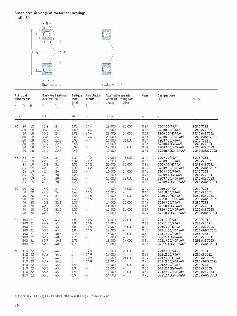
Super-precision angular contact ball bearings
d 40 – 60 mm
40 80 18 33,8 24 1,02 14,4 18 000 30 000 0,37 7208 CD/P4A1) E 240 7CE180 18 33,8 24 1,02 14,4 18 000 – 0,38 S7208 CD/P4A1) E 240 /S 7CE180 18 33,8 24 1,02 14,4 22 000 34 000 0,33 7208 CD/HCP4A1) E 240 /NS 7CE180 18 33,8 24 1,02 14,4 22 000 – 0,33 S7208 CD/HCP4A1) E 240 /S/NS 7CE180 18 31,9 22,8 0,98 – 16 000 26 000 0,37 7208 ACD/P4A1) E 240 7CE380 18 31,9 22,8 0,98 – 16 000 – 0,38 S7208 ACD/P4A1) E 240 /S 7CE380 18 31,9 22,8 0,98 – 19 000 32 000 0,33 7208 ACD/HCP4A1) E 240 /NS 7CE380 18 31,9 22,8 0,98 – 19 000 – 0,33 S7208 ACD/HCP4A1) E 240 /S/NS 7CE3
45 85 19 42,3 31 1,32 14,2 17 000 28 000 0,41 7209 CD/P4A1) E 245 7CE185 19 42,3 31 1,32 14,2 17 000 – 0,42 S7209 CD/P4A1) E 245 /S 7CE185 19 42,3 31 1,32 14,2 20 000 32 000 0,34 7209 CD/HCP4A1) E 245 /NS 7CE185 19 42,3 31 1,32 14,2 20 000 – 0,35 S7209 CD/HCP4A1) E 245 /S/NS 7CE185 19 41 30 1,25 – 15 000 24 000 0,41 7209 ACD/P4A1) E 245 7CE385 19 41 30 1,25 – 15 000 – 0,42 S7209 ACD/P4A1) E 245 /S 7CE385 19 41 30 1,25 – 17 000 28 000 0,34 7209 ACD/HCP4A1) E 245 /NS 7CE385 19 41 30 1,25 – 17 000 – 0,35 S7209 ACD/HCP4A1) E 245 /S/NS 7CE3
50 90 20 44,9 34 1,43 14,5 16 000 26 000 0,46 7210 CD/P4A1) E 250 7CE190 20 44,9 34 1,43 14,5 16 000 – 0,47 S7210 CD/P4A1) E 250 /S 7CE190 20 44,9 34 1,43 14,5 19 000 30 000 0,39 7210 CD/HCP4A1) E 250 /NS 7CE190 20 44,9 34 1,43 14,5 19 000 – 0,39 S7210 CD/HCP4A1) E 250 /S/NS 7CE190 20 42,3 32,5 1,37 – 14 000 22 000 0,46 7210 ACD/P4A1) E 250 7CE390 20 42,3 32,5 1,37 – 14 000 – 0,47 S7210 ACD/P4A1) E 250 /S 7CE390 20 42,3 32,5 1,37 – 16 000 26 000 0,39 7210 ACD/HCP4A1) E 250 /NS 7CE390 20 42,3 32,5 1,37 – 16 000 – 0,39 S7210 ACD/HCP4A1) E 250 /S/NS 7CE3
55 100 21 55,3 43 1,8 14,5 14 000 22 000 0,61 7211 CD/P4A1) E 255 7CE1100 21 55,3 43 1,8 14,5 14 000 – 0,62 S7211 CD/P4A1) E 255 /S 7CE1100 21 55,3 43 1,8 14,5 17 000 26 000 0,51 7211 CD/HCP4A1) E 255 /NS 7CE1100 21 55,3 43 1,8 14,5 17 000 – 0,52 S7211 CD/HCP4A1) E 255 /S/NS 7CE1100 21 52,7 40,5 1,73 – 13 000 20 000 0,61 7211 ACD/P4A1) E 255 7CE3100 21 52,7 40,5 1,73 – 13 000 – 0,62 S7211 ACD/P4A1) E 255 /S 7CE3100 21 52,7 40,5 1,73 – 15 000 24 000 0,51 7211 ACD/HCP4A1) E 255 /NS 7CE3100 21 52,7 40,5 1,73 – 15 000 – 0,52 S7211 ACD/HCP4A1) E 255 /S/NS 7CE3
60 110 22 57,2 46,5 2 14,9 13 000 20 000 0,81 7212 CD/P4A1) E 260 7CE1110 22 57,2 46,5 2 14,9 13 000 – 0,82 S7212 CD/P4A1) E 260 /S 7CE1110 22 57,2 46,5 2 14,9 16 000 24 000 0,69 7212 CD/HCP4A1) E 260 /NS 7CE1110 22 57,2 46,5 2 14,9 16 000 – 0,71 S7212 CD/HCP4A1) E 260 /S/NS 7CE1110 22 55,3 45 1,9 – 11 000 18 000 0,81 7212 ACD/P4A1) E 260 7CE3110 22 55,3 45 1,9 – 11 000 – 0,82 S7212 ACD/P4A1) E 260 /S 7CE3110 22 55,3 45 1,9 – 14 000 22 000 0,69 7212 ACD/HCP4A1) E 260 /NS 7CE3110 22 55,3 45 1,9 – 14 000 – 0,71 S7212 ACD/HCP4A1) E 260 /S/NS 7CE3
Principal dimensions
Basic load ratings Fatigue load limit
Calculation factor
Attainable speeds Mass Designationsdynamic static when lubricating with SKF SNFA
grease oil-aird D B C C0 Pu f0
mm kN kN – r/min kg –
1) Indicates a PEEK cage as standard, otherwise the cage is phenolic resin.
d1
r1
r1
r3
r1
r4r2
r2r2
D1D d
a
B
Sealed variantOpen variant
36

Dimensions Abutment and fillet dimensions
d d1 D1 r1,2 r3,4 a da,db Da Db ra rb~ ~ min min min max max max max
mm mm
rb
ra
daDa
ra
ra
db Db
40 53,3 66,7 1,1 0,6 17 47 73 75,8 1 0,653,3 69,7 1,1 0,6 17 47 73 75,8 1 0,653,3 66,7 1,1 0,6 17 47 73 75,8 1 0,653,3 69,7 1,1 0,6 17 47 73 75,8 1 0,653,3 66,7 1,1 0,6 23 47 73 75,8 1 0,653,3 69,7 1,1 0,6 23 47 73 75,8 1 0,653,3 66,7 1,1 0,6 23 47 73 75,8 1 0,653,3 69,7 1,1 0,6 23 47 73 75,8 1 0,6
45 57,3 72,7 1,1 0,6 18 52 78 80,8 1 0,657,3 75,7 1,1 0,6 18 52 78 80,8 1 0,657,3 72,7 1,1 0,6 18 52 78 80,8 1 0,657,3 75,7 1,1 0,6 18 52 78 80,8 1 0,657,3 72,7 1,1 0,6 25 52 78 80,8 1 0,657,3 75,7 1,1 0,6 25 52 78 80,8 1 0,657,3 72,7 1,1 0,6 25 52 78 80,8 1 0,657,3 75,7 1,1 0,6 25 52 78 80,8 1 0,6
50 62,3 77,7 1,1 0,6 19 57 83 85,8 1 0,662,3 80,7 1,1 0,6 19 57 83 85,8 1 0,662,3 77,7 1,1 0,6 19 57 83 85,8 1 0,662,3 80,7 1,1 0,6 19 57 83 85,8 1 0,662,3 77,7 1,1 0,6 26 57 83 85,8 1 0,662,3 80,7 1,1 0,6 26 57 83 85,8 1 0,662,3 77,7 1,1 0,6 26 57 83 85,8 1 0,662,3 80,7 1,1 0,6 26 57 83 85,8 1 0,6
55 68,9 86,1 1,5 0,6 21 64 91 95,8 1,5 0,668,9 89,1 1,5 0,6 21 64 91 95,8 1,5 0,668,9 86,1 1,5 0,6 21 64 91 95,8 1,5 0,668,9 89,1 1,5 0,6 21 64 91 95,8 1,5 0,668,9 86,1 1,5 0,6 29 64 91 95,8 1,5 0,668,9 89,1 1,5 0,6 29 64 91 95,8 1,5 0,668,9 86,1 1,5 0,6 29 64 91 95,8 1,5 0,668,9 89,1 1,5 0,6 29 64 91 95,8 1,5 0,6
60 76,4 93,6 1,5 0,6 22 69 101 105,8 1,5 0,676,4 96,8 1,5 0,6 22 69 101 105,8 1,5 0,676,4 93,6 1,5 0,6 22 69 101 105,8 1,5 0,676,4 96,8 1,5 0,6 22 69 101 105,8 1,5 0,676,4 93,6 1,5 0,6 31 69 101 105,8 1,5 0,676,4 96,8 1,5 0,6 31 69 101 105,8 1,5 0,676,4 93,6 1,5 0,6 31 69 101 105,8 1,5 0,676,4 96,8 1,5 0,6 31 69 101 105,8 1,5 0,6
C
37
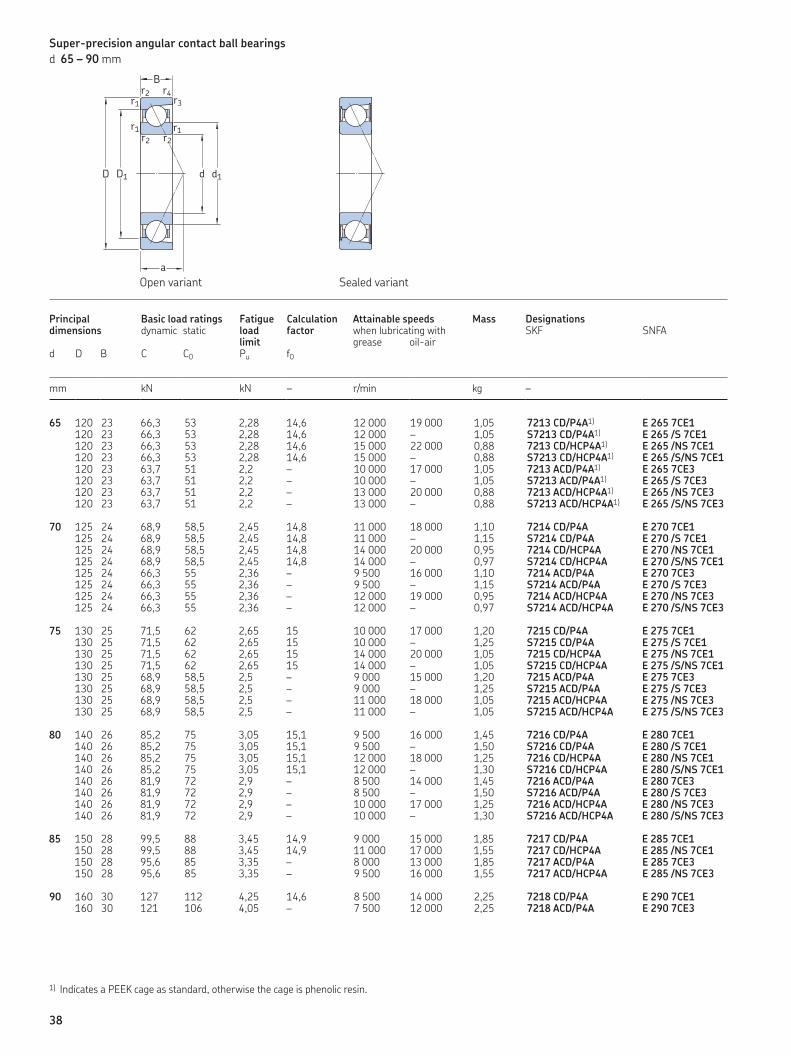
Super-precision angular contact ball bearings
d 65 – 90 mm
65 120 23 66,3 53 2,28 14,6 12 000 19 000 1,05 7213 CD/P4A1) E 265 7CE1120 23 66,3 53 2,28 14,6 12 000 – 1,05 S7213 CD/P4A1) E 265 /S 7CE1120 23 66,3 53 2,28 14,6 15 000 22 000 0,88 7213 CD/HCP4A1) E 265 /NS 7CE1120 23 66,3 53 2,28 14,6 15 000 – 0,88 S7213 CD/HCP4A1) E 265 /S/NS 7CE1120 23 63,7 51 2,2 – 10 000 17 000 1,05 7213 ACD/P4A1) E 265 7CE3120 23 63,7 51 2,2 – 10 000 – 1,05 S7213 ACD/P4A1) E 265 /S 7CE3120 23 63,7 51 2,2 – 13 000 20 000 0,88 7213 ACD/HCP4A1) E 265 /NS 7CE3120 23 63,7 51 2,2 – 13 000 – 0,88 S7213 ACD/HCP4A1) E 265 /S/NS 7CE3
70 125 24 68,9 58,5 2,45 14,8 11 000 18 000 1,10 7214 CD/P4A E 270 7CE1125 24 68,9 58,5 2,45 14,8 11 000 – 1,15 S7214 CD/P4A E 270 /S 7CE1125 24 68,9 58,5 2,45 14,8 14 000 20 000 0,95 7214 CD/HCP4A E 270 /NS 7CE1125 24 68,9 58,5 2,45 14,8 14 000 – 0,97 S7214 CD/HCP4A E 270 /S/NS 7CE1125 24 66,3 55 2,36 – 9 500 16 000 1,10 7214 ACD/P4A E 270 7CE3125 24 66,3 55 2,36 – 9 500 – 1,15 S7214 ACD/P4A E 270 /S 7CE3125 24 66,3 55 2,36 – 12 000 19 000 0,95 7214 ACD/HCP4A E 270 /NS 7CE3125 24 66,3 55 2,36 – 12 000 – 0,97 S7214 ACD/HCP4A E 270 /S/NS 7CE3
75 130 25 71,5 62 2,65 15 10 000 17 000 1,20 7215 CD/P4A E 275 7CE1130 25 71,5 62 2,65 15 10 000 – 1,25 S7215 CD/P4A E 275 /S 7CE1130 25 71,5 62 2,65 15 14 000 20 000 1,05 7215 CD/HCP4A E 275 /NS 7CE1130 25 71,5 62 2,65 15 14 000 – 1,05 S7215 CD/HCP4A E 275 /S/NS 7CE1130 25 68,9 58,5 2,5 – 9 000 15 000 1,20 7215 ACD/P4A E 275 7CE3130 25 68,9 58,5 2,5 – 9 000 – 1,25 S7215 ACD/P4A E 275 /S 7CE3130 25 68,9 58,5 2,5 – 11 000 18 000 1,05 7215 ACD/HCP4A E 275 /NS 7CE3130 25 68,9 58,5 2,5 – 11 000 – 1,05 S7215 ACD/HCP4A E 275 /S/NS 7CE3
80 140 26 85,2 75 3,05 15,1 9 500 16 000 1,45 7216 CD/P4A E 280 7CE1140 26 85,2 75 3,05 15,1 9 500 – 1,50 S7216 CD/P4A E 280 /S 7CE1140 26 85,2 75 3,05 15,1 12 000 18 000 1,25 7216 CD/HCP4A E 280 /NS 7CE1140 26 85,2 75 3,05 15,1 12 000 – 1,30 S7216 CD/HCP4A E 280 /S/NS 7CE1140 26 81,9 72 2,9 – 8 500 14 000 1,45 7216 ACD/P4A E 280 7CE3140 26 81,9 72 2,9 – 8 500 – 1,50 S7216 ACD/P4A E 280 /S 7CE3140 26 81,9 72 2,9 – 10 000 17 000 1,25 7216 ACD/HCP4A E 280 /NS 7CE3140 26 81,9 72 2,9 – 10 000 – 1,30 S7216 ACD/HCP4A E 280 /S/NS 7CE3
85 150 28 99,5 88 3,45 14,9 9 000 15 000 1,85 7217 CD/P4A E 285 7CE1150 28 99,5 88 3,45 14,9 11 000 17 000 1,55 7217 CD/HCP4A E 285 /NS 7CE1150 28 95,6 85 3,35 – 8 000 13 000 1,85 7217 ACD/P4A E 285 7CE3150 28 95,6 85 3,35 – 9 500 16 000 1,55 7217 ACD/HCP4A E 285 /NS 7CE3
90 160 30 127 112 4,25 14,6 8 500 14 000 2,25 7218 CD/P4A E 290 7CE1160 30 121 106 4,05 – 7 500 12 000 2,25 7218 ACD/P4A E 290 7CE3
Principal dimensions
Basic load ratings Fatigue load limit
Calculation factor
Attainable speeds Mass Designationsdynamic static when lubricating with SKF SNFA
grease oil-aird D B C C0 Pu f0
mm kN kN – r/min kg –
1) Indicates a PEEK cage as standard, otherwise the cage is phenolic resin.
d1
r1
r1
r3
r1
r4r2
r2r2
D1D d
a
B
Sealed variantOpen variant
38

65 82,9 102,1 1,5 0,6 24 74 111 115,8 1,5 0,682,9 105,3 1,5 0,6 24 74 111 115,8 1,5 0,682,9 102,1 1,5 0,6 24 74 111 115,8 1,5 0,682,9 105,3 1,5 0,6 24 74 111 115,8 1,5 0,682,9 102,1 1,5 0,6 33 74 111 115,8 1,5 0,682,9 105,3 1,5 0,6 33 74 111 115,8 1,5 0,682,9 102,1 1,5 0,6 33 74 111 115,8 1,5 0,682,9 105,3 1,5 0,6 33 74 111 115,8 1,5 0,6
70 87,9 107,1 1,5 0,6 25 79 116 120,8 1,5 0,687,9 110,3 1,5 0,6 25 79 116 120,8 1,5 0,687,9 107,1 1,5 0,6 25 79 116 120,8 1,5 0,687,9 110,3 1,5 0,6 25 79 116 120,8 1,5 0,687,9 107,1 1,5 0,6 35 79 116 120,8 1,5 0,687,9 110,3 1,5 0,6 35 79 116 120,8 1,5 0,687,9 107,1 1,5 0,6 35 79 116 120,8 1,5 0,687,9 110,3 1,5 0,6 35 79 116 120,8 1,5 0,6
75 92,9 112,1 1,5 0,6 26 84 121 125,8 1,5 0,692,9 115,3 1,5 0,6 26 84 121 125,8 1,5 0,692,9 112,1 1,5 0,6 26 84 121 125,8 1,5 0,692,9 115,3 1,5 0,6 26 84 121 125,8 1,5 0,692,9 112,1 1,5 0,6 37 84 121 125,8 1,5 0,692,9 115,3 1,5 0,6 37 84 121 125,8 1,5 0,692,9 112,1 1,5 0,6 37 84 121 125,8 1,5 0,692,9 115,3 1,5 0,6 37 84 121 125,8 1,5 0,6
80 99,5 120,5 2 1 28 91 129 134,4 2 199,5 124,3 2 1 28 91 129 134,4 2 199,5 120,5 2 1 28 91 129 134,4 2 199,5 124,3 2 1 28 91 129 134,4 2 199,5 120,5 2 1 39 91 129 134,4 2 199,5 124,3 2 1 39 91 129 134,4 2 199,5 120,5 2 1 39 91 129 134,4 2 199,5 124,3 2 1 39 91 129 134,4 2 1
85 106,5 129,5 2 1 30 96 139 144,4 2 1106,5 129,5 2 1 30 96 139 144,4 2 1106,5 129,5 2 1 42 96 139 144,4 2 1106,5 129,5 2 1 42 96 139 144,4 2 1
90 111,6 138,4 2 1 32 101 149 154,4 2 1111,6 138,4 2 1 44 101 149 154,4 2 1
Dimensions Abutment and fillet dimensions
d d1 D1 r1,2 r3,4 a da,db Da Db ra rb~ ~ min min min max max max max
mm mm
rb
ra
daDa
ra
ra
db Db
C
39

Super-precision angular contact ball bearings
d 95 – 140 mm
95 170 32 138 120 4,40 14,6 8 000 13 000 2,70 7219 CD/P4A E 295 7CE1170 32 133 114 4,25 – 7 500 12 000 2,70 7219 ACD/P4A E 295 7CE3
100 180 34 156 137 4,9 14,5 7 500 12 000 3,25 7220 CD/P4A E 200/100 7CE1180 34 148 129 4,65 – 7 000 11 000 3,25 7220 ACD/P4A E 200/100 7CE3
105 190 36 172 153 5,3 14,5 7 500 12 000 3,85 7221 CD/P4A E 200/105 7CE1190 36 163 146 5,1 – 6 700 10 000 3,85 7221 ACD/P4A E 200/105 7CE3
110 200 38 178 166 5,6 14,7 7 000 11 000 4,65 7222 CD/P4A E 200/110 7CE1200 38 168 160 5,4 – 6 700 10 000 4,65 7222 ACD/P4A E 200/110 7CE3
120 215 40 199 193 6,3 14,6 6 700 10 000 5,40 7224 CD/P4A E 200/120 7CE1215 40 190 183 6 – 6 000 9 000 5,40 7224 ACD/P4A E 200/120 7CE3
130 230 40 216 224 6,95 14,9 6 300 9 500 6,35 7226 CD/P4A E 200/130 7CE1230 40 203 212 6,7 – 5 600 8 500 6,35 7226 ACD/P4A E 200/130 7CE3
140 250 42 221 240 7,35 15,2 5 600 8 500 8,15 7228 CD/P4A E 200/140 7CE1250 42 212 228 6,95 – 5 000 7 500 8,15 7228 ACD/P4A E 200/140 7CE3
Principal dimensions
Basic load ratings Fatigue load limit
Calculation factor
Attainable speeds Mass Designationsdynamic static when lubricating with SKF SNFA
grease oil-aird D B C C0 Pu f0
mm kN kN – r/min kg –
d1
r1
r1
r3
r1
r4r2
r2r2
D1D d
a
B
Sealed variantOpen variant
40

95 118,1 146,9 2,1 1,1 34 107 158 163 2,1 1118,1 146,9 2,1 1,1 47 107 158 163 2,1 1
100 124,7 155,3 2,1 1,1 36 112 168 173 2,1 1124,7 155,3 2,1 1,1 50 112 168 173 2,1 1
105 131,2 163,8 2,1 1,1 38 117 178 183 2,1 1131,2 163,8 2,1 1,1 53 117 178 183 2,1 1
110 138,7 171,3 2,1 1,1 40 122 188 193 2,1 1138,7 171,3 2,1 1,1 55 122 188 193 2,1 1
120 150,3 186,7 2,1 1,1 43 132 203 208 2,1 1150,3 186,7 2,1 1,1 60 132 203 208 2,1 1
130 162,8 199,2 3 1,1 44 144 216 223 2,5 1162,8 199,2 3 1,1 62 144 216 223 2,5 1
140 176,9 213,2 3 1,5 47 154 236 241 2,5 1,5176,9 213,2 3 1,5 67 154 236 241 2,5 1,5
Dimensions Abutment and fillet dimensions
d d1 D1 r1,2 r3,4 a da,db Da Db ra rb~ ~ min min min max max max max
mm mm
rb
ra
daDa
ra
ra
db Db
C
41

Setting the highest standard for precision bearings
SKF has developed and is continuing to
develop a new, improved generation of
super-precision bearings. The new assort-
ment delivers improved accuracy and
extended bearing service life when com-
pared to previous designs.
Table 1 on page 44 and 45 provides an
overview of the new assortment of SKF
super-precision bearings.
Super-precision angular contact ball bearings
Bearings in the 718 (SEA) series
Bearings in the 718 (SEA) series provide
optimum performance in applications where
a low cross section and high degree of rigid-
ity, speed and superior accuracy are critical
design parameters. They are particularly
suitable for machine tool applications, mul-
tispindle drilling heads, robotic arms, meas-
uring devices, racing car wheels and other
precision applications. The standard assort-
ment accommodates shaft diameters rang-
ing from 10 to 160 mm.
Bearings in the 719 .. D (SEB) and 70 .. D (EX) series
For applications where a high load carrying
capacity is an additional operational require-
ment, SKF offers high-capacity bearings in
the 719 .. D (SEB) and 70 .. D (EX) series.
The ability of the new design super-preci-
sion bearings in these two series to accom-
modate heavy loads in applications where
radial space is often limited, makes them an
excellent choice for demanding applications.
Open bearings in the 719 .. D (SEB) series
accommodate shaft diameters ranging from
10 to 360 mm; sealed bearings from 10 to
150 mm.
Open bearings in the 70 .. D (EX) series
accommodate shaft diameters ranging from
6 to 240 mm; sealed bearings from 10 to
150 mm.
Bearings in the 719 .. E (VEB) and 70 .. E (VEX) series
Compared to high-speed B design bearings,
high-speed E design bearings have a higher
speed capability and can accommodate
heavier loads. This desirable combination
makes these bearings an excellent choice for
demanding applications.
Open bearings in the 719 .. E (VEB) series
accommodate shaft diameters ranging from
8 to 120 mm; sealed bearings from 20 to
120 mm.
Open bearings in the 70 .. E (VEX) series
accommodate shaft diameters ranging from
6 to 120 mm; sealed bearings from 10 to
120 mm.
Bearings in the S719 .. B (HB .. /S) and S70 .. B (HX .. /S) series
High-speed sealed bearings in the S719 .. B
(HB .. /S) and S70 .. B (HX .. /S) series can
virtually eliminate the problem of premature
bearing failures resulting from contamina-
tion. The standard assortment accommo-
dates shaft diameters ranging from 30 to
120 mm. These relubrication-free bearings
are particularly suitable for metal cutting
and woodworking machines. The bearings
are also available in an open variant.
42

Bearings made from NitroMax steel
In extremely demanding applications such
as high-speed machining centres and mill-
ing machines, bearings are frequently sub-
jected to difficult operating conditions such
as very high speeds, thin-film lubrication
conditions, and contaminated and corrosive
environments. To enable longer bearing
service life and reduce the costs associated
with downtime, SKF has developed a supe-
rior high-nitrogen steel.
The SKF assortment of super-precision
angular contact ball bearings made from
NitroMax steel have ceramic (bearing grade
silicon nitride) rolling elements as standard.
Super-precision cylindrical roller bearings
SKF produces super-precision single row
and double row cylindrical roller bearings.
The characteristic features of these bearings
are a low cross sectional height, high load
carrying capacity, high rigidity and high-
speed capability. They are therefore particu-
larly well suited for machine tool spindles
where the bearing arrangement must
accommodate heavy radial loads and high
speeds, while providing a high degree of
stiffness.
Single row cylindrical roller bearings are
produced in the N 10 series as basic design
bearings and as high-speed design bear-
ings. High-speed single row cylindrical roller
bearings in the N 10 series are available
with a tapered bore only and for shaft diam-
eters ranging from 40 to 80 mm. Compared
to previous high-speed design, they can
accommodate a speed increase of up to 30%
in grease lubricated applications and up to
15% in oil-air lubricated applications.
Double row cylindrical roller bearings are
produced as standard in the NN design and
NNU design.
Super-precision double direction angular contact thrust ball bearings
Double direction angular contact bearings,
as their name implies, were developed by
SKF to axially locate machine tool spindles
in both directions.
The new optimized design of super-pre-
cision bearings in the BTW series consists of
a set of two single row angular contact
thrust ball bearings, arranged back-to-back.
This configuration enables the bearings to
accommodate axial loads in both directions
while providing a high degree of system
rigidity. These bearings can accommodate
higher speeds compared to bearings in the
former 2344(00) series. The bearings are
available for shaft diameters ranging from
35 to 200 mm.
The redesigned high-speed BTM series
accommodate higher speeds, anywhere
from 6% to 12% depending on the size; mini-
mize heat generation, even at higher
speeds; provide high load carrying capacity
and maintain a high degree of system rigid-
ity. The range of BTM bearings series has
been expanded to accommodate shaft
diameters from 60 to 180 mm.
Super-precision angular contact thrust ball bearings for screw drives
Single direction angular contact thrust ball
bearings in the BSA and BSD (BS) series are
available for shaft diameters ranging from
12 to 75 mm. These bearings are charac-
terized by superior axial stiffness and high
axial load carrying capacity.
Double direction angular contact thrust
ball bearings in the BEAS series have been
developed for machine tool applications
where space is tight and easy mounting is
required. The bearings are available for shaft
diameters ranging from 8 to 30 mm. Bear-
ings in the BEAM series, which can accom-
modate shaft diameters ranging from 12 to
60 mm, can be bolt-mounted to an associ-
ated component.
Cartridge units are another solution for
simple and quick mounting. Units in the
FBSA (BSDU and BSQU) series incorporate
SKF single direction angular contact thrust
ball bearings and can accommodate shaft
diameters ranging from 20 to 60 mm.
Super-precision axial-radial cylindrical roller bearings
SKF axial-radial cylindrical roller bearings
are suitable for arrangements that have
simultaneously acting (radial and axial)
loads as well as moment loads.
Their internal design, together with close
tolerance manufacturing processes, enable
these bearings to attain better than P4 run-
ning accuracy.
Axial-radial cylindrical roller bearings are
commonly used to support rotating tables,
indexing tables and milling heads.
D
43

Table 1
Overview of SKF super-precision bearings
ISOdimensionseries
Bearing type and design Variant SKF assortment SKF publication1,2) SKF bearings in the series
18 Angular contact ball bearings: Basic designSuper-precision angular contact ball bearings: 718 (SEA) series (Publication No. 06810)
Open All-steel 718 .. D (SEA)Hybrid 718 .. D/HC (SEA /NS)
19 Angular contact ball bearings: High-speed, B designSuper-precision angular contact ball bearings: High-speed, B design, sealed as standard (Publication No. 06939)
Open All-steel 719 .. B (HB)Hybrid 719 .. B/HC (HB /NS)
Sealed All-steel S719 .. B (HB /S)Hybrid S719 .. B/HC (HB /S/NS)
Angular contact ball bearings: High-speed, E designSuper-precision angular contact ball bearings: High-speed, E design (Publication No. 10112)
Open All-steel 719 .. E (VEB)Hybrid 719 .. E/HC (VEB /NS)
Sealed All-steel S719 .. E (VEB /S)Hybrid S719 .. E/HC (VEB /S/NS)
Angular contact ball bearings: High-capacity, basic designSuper-precision angular contact ball bearings: High-capacity 719 .. D (SEB) and 70 .. D (EX) series (Publication No. 10527)
Open All-steel 719 .. D (SEB)Hybrid 719 .. D/HC (SEB /NS)
Sealed All-steel S719 .. D (SEB /S)Hybrid S719 .. D/HC (SEB /S/NS)
10 Angular contact ball bearings: High-speed, B designSuper-precision angular contact ball bearings: High-speed, B design, sealed as standard (Publication No. 06939)
Open All-steel 70 .. B (HX)Hybrid 70 .. B/HC (HX /NS)
Sealed All-steel S70 .. B (HX /S)Hybrid S70 .. B/HC (HX /S/NS)
Angular contact ball bearings: High-speed, E designSuper-precision angular contact ball bearings: High-speed, E design (Publication No. 10112)
Open All-steel 70 .. E (VEX)Hybrid 70 .. E/HC (VEX /NS)
Sealed All-steel S70 .. E (VEX /S)Hybrid S70 .. E/HC (VEX /S/NS)
Angular contact ball bearings: High-capacity, basic designSuper-precision angular contact ball bearings: High-capacity 719 .. D (SEB) and 70 .. D (EX) series (Publication No. 10527)
Open All-steel 70 .. D (EX)Hybrid 70 .. D/HC (EX /NS)
Sealed All-steel S70 .. D (EX /S)Hybrid S70 .. D/HC (EX /S/NS)
02 Angular contact ball bearings: High-capacity, basic designSuper-precision angular contact ball bearings: High-capacity (Publication No. 06981)
Open All-steel 72 .. D (E 200)Hybrid 72 .. D/HC (E 200 /NS)
Sealed All-steel S72 .. D (E 200 /S)Hybrid S72 .. D/HC (E 200 /S/NS)
49 Double row cylindrical roller bearings: NNU design
Open All-steel NNU 49 BK
1) Where applicable, information can be found in the SKF publication High-precision bearings (Publication No. 6002).2) For additional information about super-precision angular contact ball bearings made from NitroMax steel, refer to the SKF publication Extend bearing service life with NitroMax (Publication No. 10126).
44

cont. Table 1
Overview of SKF super-precision bearings
ISOdimensionseries
Bearing type and design Variant SKF assortment SKF publication1,2) SKF bearings in the series
10 Single row cylindrical roller bearings: Basic design
Open All-steel N 10 KTNHybrid N 10 KTN/HC5
Single row cylindrical roller bearings: High-speed designSuper-precision cylindrical roller bearings: High-speed (Publication No. 07016)
Open All-steel N 10 KPHAHybrid N 10 KPHA/HC5
30 Double row cylindrical roller bearings: NN design
Open All-steel NN 30 KTNHybrid NN 30 KTN/HC5
– (Non-standardized)
Angular contact thrust ball bearings: Double direction, basic designSuper-precision double direction angular contact thrust ball bearings (Publication No. 10097)
Open All-steel BTWHybrid BTW /HC
Angular contact thrust ball bearings: Double direction, high-speed designHigher-speed capability with the new BTM bearing series design (Publication No. 12119)
Open All-steel BTMHybrid BTM /HC
02 Angular contact thrust ball bearings: Single directionSuper-precision angular contact thrust ball bearings for screw drives (Publication No. 06570)
Open All-steel BSA 2 (BS 200)Sealed All-steel BSA 2 .. (BS 200 ..)
03 Angular contact thrust ball bearings: Single directionSuper-precision angular contact thrust ball bearings for screw drives (Publication No. 06570)
Open All-steel BSA 3 (BS 3)Sealed All-steel BSA 3 .. (BS 3 ..)
– (Non-standardized)
Angular contact thrust ball bearings: Single directionSuper-precision angular contact thrust ball bearings for screw drives (Publication No. 06570)
Open All-steel BSD (BS ../)Sealed All-steel BSD .. (BS ..)
Angular contact thrust ball bearings: Double direction
Sealed All-steel BEAS (BEAS)BEAM (BEAM)
Cartridge unit with angular contact thrust ball bearings
Sealed All-steel FBSA (BSDU, BSQU)–
1) Where applicable, information can be found in the SKF publication High-precision bearings (Publication No. 6002).2) For additional information about super-precision angular contact ball bearings made from NitroMax steel, refer to the SKF publication Extend bearing service life with NitroMax (Publication No. 10126).
D
45

From one simple but
inspired solution to
a misalignment
problem in a textile
mill in Sweden, and
fifteen employees in
1907, SKF has
grown to become a
global industrial
knowledge leader.
Over the years, we have built on our exper-
tise in bearings, extending it to seals, mecha-
tronics, services and lubrication systems.
Our knowledge network includes 46 000
employees, 15 000 distributor partners,
offices in more than 130 countries, and a
growing number of SKF Solution Factory
sites around the world.
Research and development
We have hands-on experience in over forty
industries based on our employees’ know-
ledge of real life conditions. In addition, our
world-leading experts and university part-
ners pioneer advanced theoretical research
and development in areas including tribol-
ogy, condition monitoring, asset manage-
ment and bearing life theory. Our ongoing
commitment to research and devel opment
helps us keep our customers at the forefront
of their industries.
Meeting the toughest challenges
Our network of knowledge and experience,
along with our understanding of how our
core technologies can be combined, helps
us create innovative solutions that meet the
toughest of challenges. We work closely with
our customers throughout the asset life
cycle, helping them to profitably and
re spon sibly grow their businesses.
SKF Solution Factory makes SKF knowledge and manu facturing expertise available locally to provide unique solutions and services to our customers.
Working with SKF IT and logistics systems and application experts, SKF Authorized Distributors deliver a valuable mix of product and application knowledge to customers worldwide.
Working for a sustainable future
Since 2005, SKF has worked to reduce the
negative environmental impact from our
operations and those of our suppliers. Our
continuing technology development resulted
in the introduction of the SKF BeyondZero
portfolio of products and services which im-
prove efficiency and reduce energy losses,
as well as enable new technol ogies har-
nessing wind, solar and ocean power. This
combined approach helps reduce the en vir-
on mental impact both in our oper ations and
our customers’ oper ations.
SKF – the knowledge engineering company
46
BearingsSKF is the world leader in the design, development and manufacture of high performance rolling bearings, plain bearings, bearing units and housings.
Machinery maintenanceCondition monitoring technologies and main-tenance services from SKF can help minimize unplanned downtime, improve operational efficiency and reduce maintenance costs.
Sealing solutionsSKF offers standard seals and custom engineered sealing solutions to increase uptime, improve machine reliability, reduce friction and power losses, and extend lubricant life.
MechatronicsSKF fly-by-wire systems for aircraft and drive-by-wire systems for off-road, agricultural and forklift applications replace heavy, grease or oil consuming mechanical and hydraulic systems.
Lubrication solutionsFrom specialized lubricants to state-of-the-art lubrication systems and lubrication management ser vices, lubrication solutions from SKF can help to reduce lubrication related downtime and lubricant consumption.
Actuation and motion controlWith a wide assortment of products – from actu-ators and ball screws to profile rail guides – SKF can work with you to solve your most pressing linear system challenges.
Our knowledge – your successSKF Life Cycle Management is how we combine our technology
platforms and advanced ser vices, and apply them at each stage
of the asset life cycle, to help our customers to be more
success ful, sustainable and profitable.
Working closely with you
Our objective is to help our customers
improve productivity, minimize main ten-
ance, achieve higher energy and resource
efficiency, and optimize designs for long
service life and reliability.
Innovative solutions
Whether the application is linear or rotary
or a combination, SKF engineers can work
with you at each stage of the asset life cycle
to improve machine performance by looking
at the entire application. This approach
doesn’t just focus on individual components
like bearings or seals. It looks at the whole
application to see how each com po nent in-
teracts with each other.
Design optimization and verification
SKF can work with you to optimize current
or new designs with proprietary 3-D mod-
ell ing software that can also be used as a
virtual test rig to confirm the integrity of the
design.
SKF Life Cycle Management
Design and developManufacture and test
Spec
ifica
tion
Install a
nd com
mis
sion
Operate and monitor
Maintain and repair
D
47

Bearings and units
SealsLubrication
systems
Mechatronics Services
The Power of Knowledge Engineering
Drawing on five areas of competence and application-specific expertise amassed over more than 100
years, SKF brings innovative solutions to OEMs and production facilities in every major industry world-
wide. These five competence areas include bearings and units, seals, lubrication systems, mechatronics
(combining mechanics and electronics into intelligent systems), and a wide range of services, from 3-D
computer modelling to advanced condition monitoring and reliability and asset management systems.
A global presence provides SKF customers uniform quality standards and worldwide product availability.
® SKF and SNFA are registered trademarks of the SKF Group.
© SKF Group 2012The contents of this publication are the copyright of the publisher and may not be reproduced (even extracts) unless prior written permission is granted. Every care has been taken to ensure the accuracy of the information contained in this publication but no liability can be accepted for any loss or damage whether direct, indirect or consequential arising out of the use of the information contained herein.
PUB BU/P2 06981/5 EN · May 2012
This publication supersedes all information about SKF bearings in the 72 .. D series in the SKF publica-tion High-precision bearings (Publication No. 6002), and SNFA bearings in the E 200 series in the SNFA General Catalogue.
www.skf.com/superprecisionbearings