Sunny Data Control - Technical Descriptionfiles.sma.de/dl/1364/SDC-TEN081450.pdf · 4. 2...
156
Solar data technology SUNNY DATA CONTROL SDC-TEN081450 | Version 5.0 EN Technical Description
-
Upload
trinhnguyet -
Category
Documents
-
view
224 -
download
5
Transcript of Sunny Data Control - Technical Descriptionfiles.sma.de/dl/1364/SDC-TEN081450.pdf · 4. 2...

Solar data technologySUNNY DATA CONTROL
SDC-TEN081450 | Version 5.0 EN
Technical Description

SMA Technologie AG Table of Contents
Technical Description SDC-TEN081450 2
Table of Content
1 Notes on this Manual. . . . . . . . . . . . . . . . . . . . . . . . . . . . . . 9
1. 1 Target Group . . . . . . . . . . . . . . . . . . . . . . . . . . . . . . . . . . . . . . . 9
1. 2 Validity . . . . . . . . . . . . . . . . . . . . . . . . . . . . . . . . . . . . . . . . . . . . 9
1. 3 Symbols Used. . . . . . . . . . . . . . . . . . . . . . . . . . . . . . . . . . . . . . . 9
1. 4 Definitions . . . . . . . . . . . . . . . . . . . . . . . . . . . . . . . . . . . . . . . . . 101.4. 1 Syntax . . . . . . . . . . . . . . . . . . . . . . . . . . . . . . . . . . . . . . . . . . . . . . . . . . . . . . 10
2 Safety . . . . . . . . . . . . . . . . . . . . . . . . . . . . . . . . . . . . . . . . . 11
2. 1 Appropriate Usage . . . . . . . . . . . . . . . . . . . . . . . . . . . . . . . . . 12
3 Sunny Data Control . . . . . . . . . . . . . . . . . . . . . . . . . . . . . . 13
3. 1 What is new? . . . . . . . . . . . . . . . . . . . . . . . . . . . . . . . . . . . . . . 13
3. 2 Software Version . . . . . . . . . . . . . . . . . . . . . . . . . . . . . . . . . . . 13
3. 3 Functions. . . . . . . . . . . . . . . . . . . . . . . . . . . . . . . . . . . . . . . . . . 13
3. 4 System Requirements . . . . . . . . . . . . . . . . . . . . . . . . . . . . . . . . 14
4 Connecting the PC to an Inverter . . . . . . . . . . . . . . . . . . . 15
4. 1 Connection via the USB service interface . . . . . . . . . . . . . . . . 15
4. 2 Communication via Bluetooth . . . . . . . . . . . . . . . . . . . . . . . . . 16
4. 3 Connection via RS485 and an interface converter . . . . . . . . . 16
5 Connecting the PC to a Communication Device. . . . . . . . 17
5. 1 Notes on the Use of Level Converters . . . . . . . . . . . . . . . . . . . 20
5. 2 Sunny Boy Control / Plus . . . . . . . . . . . . . . . . . . . . . . . . . . . . . 215.2. 1 Connection via RS232 . . . . . . . . . . . . . . . . . . . . . . . . . . . . . . . . . . . . . . . . . 215.2. 2 Connection via RS485 . . . . . . . . . . . . . . . . . . . . . . . . . . . . . . . . . . . . . . . . . 235.2. 3 Connection via the Analog Modem NET Piggy-Back . . . . . . . . . . . . . . . . . 275.2. 4 Connection via the ISDN NET Piggy-Back . . . . . . . . . . . . . . . . . . . . . . . . . 285.2. 5 Connection via the GSM NET Piggy-Back. . . . . . . . . . . . . . . . . . . . . . . . . . 295.2. 6 Connection via the Ethernet NET Piggy-Back. . . . . . . . . . . . . . . . . . . . . . . . 30
5. 3 Sunny Beam . . . . . . . . . . . . . . . . . . . . . . . . . . . . . . . . . . . . . . . 31

Table of Contents SMA Technologie AG
3 SDC-TEN081450 Technical Description
5.3. 1 Connection via USB . . . . . . . . . . . . . . . . . . . . . . . . . . . . . . . . . . . . . . . . . . . 31
6 Installation . . . . . . . . . . . . . . . . . . . . . . . . . . . . . . . . . . . . . 32
6. 1 Installing Sunny Data Control . . . . . . . . . . . . . . . . . . . . . . . . . 32
7 Sunny Data Control User Interface. . . . . . . . . . . . . . . . . . 33
7. 1 Menu Area . . . . . . . . . . . . . . . . . . . . . . . . . . . . . . . . . . . . . . . . 34
7. 2 Plant tree. . . . . . . . . . . . . . . . . . . . . . . . . . . . . . . . . . . . . . . . . . 35
7. 3 Display Area . . . . . . . . . . . . . . . . . . . . . . . . . . . . . . . . . . . . . . 36
8 Initial Settings . . . . . . . . . . . . . . . . . . . . . . . . . . . . . . . . . . . 37
8. 1 Creating Plants . . . . . . . . . . . . . . . . . . . . . . . . . . . . . . . . . . . . . 378.1. 1 Changing Plant Names, Creating / Deleting Plants . . . . . . . . . . . . . . . . . . 37
8. 2 Loading a Plant. . . . . . . . . . . . . . . . . . . . . . . . . . . . . . . . . . . . . 38
8. 3 Setting the Communication Connection. . . . . . . . . . . . . . . . . . 398.3. 1 Bluetooth. . . . . . . . . . . . . . . . . . . . . . . . . . . . . . . . . . . . . . . . . . . . . . . . . . . . 398.3. 2 COM1 – COM255. . . . . . . . . . . . . . . . . . . . . . . . . . . . . . . . . . . . . . . . . . . 438.3. 3 Modem . . . . . . . . . . . . . . . . . . . . . . . . . . . . . . . . . . . . . . . . . . . . . . . . . . . . . 448.3. 4 Network . . . . . . . . . . . . . . . . . . . . . . . . . . . . . . . . . . . . . . . . . . . . . . . . . . . . 458.3. 5 Sunny Beam (USB) . . . . . . . . . . . . . . . . . . . . . . . . . . . . . . . . . . . . . . . . . . . . 478.3. 6 Setting the Transport Protocol. . . . . . . . . . . . . . . . . . . . . . . . . . . . . . . . . . . . 48
8. 4 Detecting Devices. . . . . . . . . . . . . . . . . . . . . . . . . . . . . . . . . . . 498.4. 1 Narrowing the Scope of Device Detection . . . . . . . . . . . . . . . . . . . . . . . . . 50
9 Setting Parameters (Installer) . . . . . . . . . . . . . . . . . . . . . . 51
10 Displaying Data . . . . . . . . . . . . . . . . . . . . . . . . . . . . . . . . . 53
10. 1 Creating a Device Overview . . . . . . . . . . . . . . . . . . . . . . . . . . 5410.1. 1 Displaying or Concealing Devices. . . . . . . . . . . . . . . . . . . . . . . . . . . . . . . . 5610.1. 2 Arranging the Fields . . . . . . . . . . . . . . . . . . . . . . . . . . . . . . . . . . . . . . . . . . . 5710.1. 3 Show or Hide the Grid Lines . . . . . . . . . . . . . . . . . . . . . . . . . . . . . . . . . . . . 5710.1. 4 Setting the Data Query Sequence . . . . . . . . . . . . . . . . . . . . . . . . . . . . . . . . 5710.1. 5 Maximizing the Device Overview (Online Display) . . . . . . . . . . . . . . . . . . 57
10. 2 Choose the channels for spot value readings.. . . . . . . . . . . . . 58

SMA Technologie AG
4 SDC-TEN081450 Technical Description
10. 3 Setting the Performance Display . . . . . . . . . . . . . . . . . . . . . . . 59
10. 4 Setting the Communication Quality . . . . . . . . . . . . . . . . . . . . . 60
10. 5 Changing the Color Behavior of the Device Fields . . . . . . . . . 62
10. 6 Accessing Individual Device Information. . . . . . . . . . . . . . . . . 63
10. 7 Configuring the Total Overview. . . . . . . . . . . . . . . . . . . . . . . . 64
10. 8 Managing the Device Overviews . . . . . . . . . . . . . . . . . . . . . . 6710.8. 1 Managing the Device Overviews . . . . . . . . . . . . . . . . . . . . . . . . . . . . . . . . 67
10. 9 Activating / Deactivating Spot Value Querying . . . . . . . . . . . 68
11 Managing Data and Saving Data Locally . . . . . . . . . . . . 69
11. 1 Reading Out and Saving Data from Sunny Beam. . . . . . . . . . 69
11. 2 Saving Data in Excel Format . . . . . . . . . . . . . . . . . . . . . . . . . . 70
11. 3 Saving Data in CSV Format . . . . . . . . . . . . . . . . . . . . . . . . . . . 7111.3. 1 Creating a New CSV Type . . . . . . . . . . . . . . . . . . . . . . . . . . . . . . . . . . . . . 7111.3. 2 Structure of the Standard CSV Format . . . . . . . . . . . . . . . . . . . . . . . . . . . . . 76
11. 4 Direct Data Acquisition from an Inverter. . . . . . . . . . . . . . . . . 7711.4. 1 Set data storage . . . . . . . . . . . . . . . . . . . . . . . . . . . . . . . . . . . . . . . . . . . . . . 7711.4. 2 Saving and Viewing Data . . . . . . . . . . . . . . . . . . . . . . . . . . . . . . . . . . . . . . 8011.4. 3 Sending Data to Sunny Portal . . . . . . . . . . . . . . . . . . . . . . . . . . . . . . . . . . . 80
11. 5 Setting up Sunny Boy Control Channel Recording . . . . . . . . . 81
11. 6 Reading Out Data Saved on the Sunny Boy Control . . . . . . . 8311.6. 1 Storage Time Refresh . . . . . . . . . . . . . . . . . . . . . . . . . . . . . . . . . . . . . . . . . . 8511.6. 2 Setting Time Ranges . . . . . . . . . . . . . . . . . . . . . . . . . . . . . . . . . . . . . . . . . . . 8511.6. 3 Resetting Time Ranges . . . . . . . . . . . . . . . . . . . . . . . . . . . . . . . . . . . . . . . . . 8611.6. 4 Structure of the Excel Files . . . . . . . . . . . . . . . . . . . . . . . . . . . . . . . . . . . . . . 87
11. 7 Configuring the Automatic Readout. . . . . . . . . . . . . . . . . . . . . 8911.7. 1 Starting a New Task . . . . . . . . . . . . . . . . . . . . . . . . . . . . . . . . . . . . . . . . . . . 8911.7. 2 Editing / Deleting a Task . . . . . . . . . . . . . . . . . . . . . . . . . . . . . . . . . . . . . . . 9111.7. 3 Deactivating the Automatic Readout . . . . . . . . . . . . . . . . . . . . . . . . . . . . . . 91
11. 8 Creating a Chart in Excel. . . . . . . . . . . . . . . . . . . . . . . . . . . . . 9211.8. 1 Automatic Analysis . . . . . . . . . . . . . . . . . . . . . . . . . . . . . . . . . . . . . . . . . . . . 9311.8. 2 Manual Analysis. . . . . . . . . . . . . . . . . . . . . . . . . . . . . . . . . . . . . . . . . . . . . . 95
SMA Technologie AG
Technical Description SDC-TEN081450 5
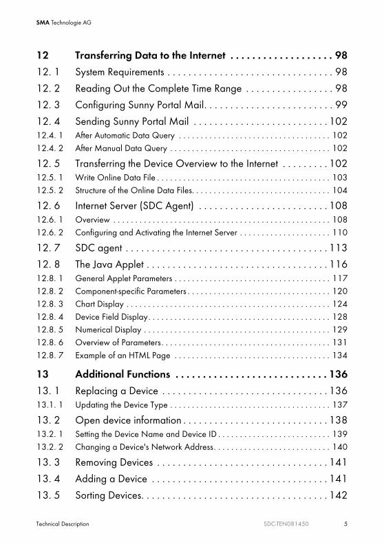
12 Transferring Data to the Internet . . . . . . . . . . . . . . . . . . . 98
12. 1 System Requirements . . . . . . . . . . . . . . . . . . . . . . . . . . . . . . . . 98
12. 2 Reading Out the Complete Time Range . . . . . . . . . . . . . . . . . 98
12. 3 Configuring Sunny Portal Mail. . . . . . . . . . . . . . . . . . . . . . . . . 99
12. 4 Sending Sunny Portal Mail . . . . . . . . . . . . . . . . . . . . . . . . . . 10212.4. 1 After Automatic Data Query . . . . . . . . . . . . . . . . . . . . . . . . . . . . . . . . . . . 10212.4. 2 After Manual Data Query . . . . . . . . . . . . . . . . . . . . . . . . . . . . . . . . . . . . . 102
12. 5 Transferring the Device Overview to the Internet . . . . . . . . . 10212.5. 1 Write Online Data File . . . . . . . . . . . . . . . . . . . . . . . . . . . . . . . . . . . . . . . . 10312.5. 2 Structure of the Online Data Files. . . . . . . . . . . . . . . . . . . . . . . . . . . . . . . . 104
12. 6 Internet Server (SDC Agent) . . . . . . . . . . . . . . . . . . . . . . . . . 10812.6. 1 Overview . . . . . . . . . . . . . . . . . . . . . . . . . . . . . . . . . . . . . . . . . . . . . . . . . . 10812.6. 2 Configuring and Activating the Internet Server . . . . . . . . . . . . . . . . . . . . . 110
12. 7 SDC agent . . . . . . . . . . . . . . . . . . . . . . . . . . . . . . . . . . . . . . . 113
12. 8 The Java Applet . . . . . . . . . . . . . . . . . . . . . . . . . . . . . . . . . . . 11612.8. 1 General Applet Parameters . . . . . . . . . . . . . . . . . . . . . . . . . . . . . . . . . . . . 11712.8. 2 Component-specific Parameters . . . . . . . . . . . . . . . . . . . . . . . . . . . . . . . . . 12012.8. 3 Chart Display . . . . . . . . . . . . . . . . . . . . . . . . . . . . . . . . . . . . . . . . . . . . . . . 12412.8. 4 Device Field Display. . . . . . . . . . . . . . . . . . . . . . . . . . . . . . . . . . . . . . . . . . 12812.8. 5 Numerical Display . . . . . . . . . . . . . . . . . . . . . . . . . . . . . . . . . . . . . . . . . . . 12912.8. 6 Overview of Parameters. . . . . . . . . . . . . . . . . . . . . . . . . . . . . . . . . . . . . . . 13112.8. 7 Example of an HTML Page . . . . . . . . . . . . . . . . . . . . . . . . . . . . . . . . . . . . 134
13 Additional Functions . . . . . . . . . . . . . . . . . . . . . . . . . . . . 136
13. 1 Replacing a Device . . . . . . . . . . . . . . . . . . . . . . . . . . . . . . . . 13613.1. 1 Updating the Device Type . . . . . . . . . . . . . . . . . . . . . . . . . . . . . . . . . . . . . 137
13. 2 Open device information . . . . . . . . . . . . . . . . . . . . . . . . . . . . 13813.2. 1 Setting the Device Name and Device ID . . . . . . . . . . . . . . . . . . . . . . . . . . 13913.2. 2 Changing a Device's Network Address. . . . . . . . . . . . . . . . . . . . . . . . . . . 140
13. 3 Removing Devices . . . . . . . . . . . . . . . . . . . . . . . . . . . . . . . . . 141
13. 4 Adding a Device . . . . . . . . . . . . . . . . . . . . . . . . . . . . . . . . . . 141
13. 5 Sorting Devices. . . . . . . . . . . . . . . . . . . . . . . . . . . . . . . . . . . . 142

SMA Technologie AG
6 SDC-TEN081450 Technical Description
13. 6 Creating a Color Palette for Device Fields . . . . . . . . . . . . . . 142
13. 7 Changing the Fonts of Device Fields . . . . . . . . . . . . . . . . . . . 143
13. 8 Background Images . . . . . . . . . . . . . . . . . . . . . . . . . . . . . . . . 143
13. 9 Packet Monitor . . . . . . . . . . . . . . . . . . . . . . . . . . . . . . . . . . . . 145
13. 10 Changing the Security Level (Installer Password). . . . . . . . . . 147
13. 11 Locking the Device Overview (Online Display). . . . . . . . . . . 148
13. 12 Timeouts . . . . . . . . . . . . . . . . . . . . . . . . . . . . . . . . . . . . . . . . . 14913.12. 1 Settings for the Sunny Central Control . . . . . . . . . . . . . . . . . . . . . . . . . . . . 149
14 Troubleshooting . . . . . . . . . . . . . . . . . . . . . . . . . . . . . . . . 150
14. 1 Errors in the Use of Sunny Data Control . . . . . . . . . . . . . . . . 150
14. 2 Java Applet Error Messages . . . . . . . . . . . . . . . . . . . . . . . . . 151
14. 3 Errors in the Bluetooth Installation . . . . . . . . . . . . . . . . . . . . . 15214.3. 1 FAQ . . . . . . . . . . . . . . . . . . . . . . . . . . . . . . . . . . . . . . . . . . . . . . . . . . . . . . 153
14. 4 Setting the Language . . . . . . . . . . . . . . . . . . . . . . . . . . . . . . . 155
15 Contact . . . . . . . . . . . . . . . . . . . . . . . . . . . . . . . . . . . . . . . 156

Notes on this Manual SMA Technologie AG
Technical Description SDC-TEN081450 9
1 Notes on this Manual
1. 1 Target GroupThis documentation is intended for installers and users. Some of the activities described in this document may only be performed by qualified electricians and are marked with a danger notice.
1. 2 ValidityThis documentation for the Sunny Data Control is valid for firmware version 4.0, or later. How to display the firmware version is described in chapter 3. 2 "Software Version" (Page 13).
1. 3 Symbols UsedThe following types of safety warnings and general information are used in these instructions.
DANGER!
"DANGER" indicates a hazardous situation which, if ignored, will result in serious injury or death!
NOTICE!
"NOTICE" indicates a situation which, if ignored, could result in damage to property.
Information
Information provides tips that are valuable for the optimal installation and operation of your product.

Notes on this Manual SMA Technologie AG
10 SDC-TEN081450 Technical Description
1. 4 Definitions
1.4. 1 SyntaxThis user manual uses the terminology indicated in the following table.
Sunny Boy Control/Sunny Boy Control PlusIn these instruction uses the term "Sunny Boy Control/Plus", and it refers to the Sunny Boy Control, the Sunny Boy Control Plus, and the Sunny Central Control. The Sunny Central Control is a variant of the Sunny Boy Control which is directly built into the Sunny Central. Throughout this manual, only the Sunny Boy Control/Plus is mentioned. All sections which apply to the Sunny Boy Control/Plus also apply to the Sunny Central Control.
Example of a typographic convention Description
Click on <Ok>. These symbols represent a button.
Choose "Options / Settings" Menu items are presented in quotation marks. Multiple menu items are separated by a slash.

Safety SMA Technologie AG
Technical Description SDC-TEN081450 11
2 SafetyPlease follow all operating and safety instructions in this section. Failure to follow these instructions could result in damage to the device and in personal hazard.
DANGER!Risk of lethal electric shock!
High voltages are present in the inverter.
• Any work on the inverter must be carried out by a qualified personnel!
DANGER!Death hazard due to changes in the inverter's internal safety specifications.
Unauthorized changes to the SMA grid guard parameters cancel the operating permit.
• Changes to the SMA grid guard parameters are to be made only with the express permission of the grid operator.
When using the Internet ensure security by means of a firewall.
When the PC and Sunny Data Control are connected to the Internet parameters could be changed through unwanted access.
• Protect the PC on which Sunny Data Control is installed from unwanted access from the Internet by means of hardware and software (firewall) placed upstream from it.

Safety SMA Technologie AG
12 SDC-TEN081450 Technical Description
2. 1 Appropriate UsageSunny Data Control is a PC program which collects, stores and displays data from a PV plant. Depending on the devices connected, communication is possible through RS232, RS485 and Bluetooth.
With Sunny Data Control, plant data can be saved in Excel and/or CSV formats. In addition, with Sunny Data Control the data can be sent to Sunny Portal for their storage and display on the Internet. Further information regarding Sunny Portal can be found at www.SunnyPortal.com.
Data collected by Sunny Data Control regarding the power generated by your solar power plant can deviate from those of the electric meter. The data should not be used for billing purposes.
Supported communication devices• Sunny Boy Control/Plus (starting with firmware version 2.0)
• Sunny Central Control (starting with firmware version 2.0)
• Sunny Beam
Supported inverters for direct connection to the PC Sunny Data Control supports the direct connection of an inverter to the PC through the USB service interface with Sunny Data Control software version 3.81, and later. This connection is meant for the purpose of servicing only, and should not be used on a long-term basis.
• Sunny Boys (except SB400TL-20/5000TL-20), Sunny Mini Centrals, Windy Boy
- Through the USB-Service-Interface (SMA order number: USBPBS)
The SB 4000TL-20/5000TL-20 does not support the USB-Service-Interface. A direct connection to the PC can be achieved via Bluetooth, or optionally, via RS 485.
• SB 4000TL-20/5000TL-20
- Via BluetoothThe SB 4000TL-20/5000TL-20 is equipped with Bluetooth as a standard.The PC requires integrated Bluetooth or a Bluetooth stick and Sunny Data Control software version 4.0, or later.
- Optional via RS485The SB 4000TL-20/5000TL-20 requires the 485I module (SMA order number: DM-485CB-10).The PC requires the I-7561 interface converter from RS485 to USB.

Sunny Data Control SMA Technologie AG
Technical Description SDC-TEN081450 13
3 Sunny Data Control
3. 1 What is new?• New SDC user interface design.
• Bluetooth communication with SB4000TL-20/5000TL-20 is possible.
• New "Overview" page with the most important data of the plant or a chosen device.
3. 2 Software VersionYou can display Sunny Data Control's software version via the menu "?/Info...". The following information is displayed:
1.
• Software version and date.
• Current security level of the user, see section 13. 10 "Changing the Security Level (Installer Password)." (Page 147).
3. 3 Functions• Continuous system monitoring and acquisition of measurement data by means of access to
your Sunny Boy Control.
• Direct measurement data gathering from an inverter through its direct connection to the PC.
• Remote monitoring via modem
• Data export for the presentation of operating data on the Internet (e.g., via Sunny Portal).
• Graphic PC display of all measurement data and operating modes
• "Online display" with color-coded indication of the present output of each Sunny Boy in your plant
• Configuration of Sunny Boys and adjustment of Sunny Boys' parameters

Sunny Data Control SMA Technologie AG
14 SDC-TEN081450 Technical Description
3. 4 System Requirements• Operating systems: Windows 2000, Windows XP, Windows Vista.
• Available hard disk space: At least 20 MB
• Bluetooth
- at the PC: Integrated Bluetooth or with a Bluetooth stick.
- Supported Bluetooth stacks: Microsoft, Toshiba, BlueSoleil, BroadcomOther Bluetooth stacks can be used via a virtual COM port.
• RS232
- at the PC: COM1 to COM255
- at the Sunny Boy Control: RS232 Piggy-Back
- Data cable: up to 15 m
• RS485
- at the PC: Interface converter.
- at the Sunny Boy Control: RS485 Piggy-Back
- Data cable: Up to 1200 m
• Ethernet
- at the PC: Ethernet card
- at the Sunny Boy Control: NET socket, NET Piggy-Back
- Ethernet: Up to 100 m
• USB
- at the Sunny Beam: Up to 3 m

Connecting the PC to an Inverter SMA Technologie AG
Technical Description SDC-TEN081450 15
4 Connecting the PC to an InverterConnection of an inverter to the PC is achieved via the USB service interface, via RS485 and an interface converter, or via Bluetooth (SB 4000TL-20/5000TL-20). The SB 4000TL-20/5000TL-20 does not support the USB-Service-Interface.
The following chapters describe the respective connection types:
• Connection via the USB service interface
• Connection via Bluetooth
• Connection via RS485 and an interface converter
4. 1 Connection via the USB service interfaceRequirementsConnection via the USB service interface (SMA order number: USBPBS) is only for the purpose of servicing, and should not be used long term. The SB 4000TL-20/5000TL-20 does not support the USB-Service-Interface.
ConnectionFor further information regarding this connection, please refer to the USB service interface's user manual.
Data GatheringChapter 11. 4 "Direct Data Acquisition from an Inverter" (Page 77) describes how to acquire and save data from an inverter connected directly to the PC, and how to send these to Sunny Portal.

Connecting the PC to an Inverter SMA Technologie AG
16 SDC-TEN081450 Technical Description
4. 2 Communication via BluetoothRequirementsBluetooth is integrated as standard in SB 4000TL-20/5000TL-20. The PC or laptop must be equipped with Bluetooth. If Bluetooth is fitted, the range is usually of up to only 10 m. If a Bluetooth stick is retrofitted, however, this range is greater; in the case of Bluetooth Class 1 it is up to 100 m.
CommissioningThe commissioning of Bluetooth communication is described in chapter 8.3. 1 "Bluetooth" (Page 39).
Data GatheringChapter 11. 4 "Direct Data Acquisition from an Inverter" (Page 77) describes how to acquire and save data from an inverter connected directly to the PC, and how to send these to Sunny Portal.
4. 3 Connection via RS485 and an interface converterRequirementsThe inverter must be equipped with a RS485 Piggy-Back. The I-7561 interface converter from RS485 to USB is needed for connection to the PC via RS485 (SMA order number: I-7561), see also chapter 5. 1 "Notes on the Use of Level Converters" (Page 20).
ConnectionInformation on this connection is provided in the I-7561 installation guide.
Data GatheringChapter 11. 4 "Direct Data Acquisition from an Inverter" (Page 77) describes how to acquire and save data from an inverter connected directly to the PC, and how to send these to Sunny Portal.
Data cannot be sent to Sunny Portal.
If the data from SB 4000TL-20/5000TL-20 is queried via Bluetooth, it cannot be sent to Sunny Portal.
• In order to be able to send the data from SB 4000TL-20/5000TL-20 to Sunny Portal, it must be queried via RS485 communication.
Grid guard parameters in SB4000TL-20/5000TL-20 via Bluetooth.
If the SB4000TL-20/5000TL-20 is connected with Sunny Data Control via Bluetooth, the SMA grid guard parameter can be set using the padlock icon at the top right on the "Parameters" page.

Connecting the PC to a Communication Device SMA Technologie AG
Technical Description SDC-TEN081450 17
5 Connecting the PC to a Communication DeviceIn order to connect several inverters to the PC there are various communication devices at your disposal. It is only ever possible to have one single type of connection to the communication device, as well as between the inverters.
RS232 is a 1:1 connection with which only one inverter can be connected to only one communication device.

Connecting the PC to a Communication Device SMA Technologie AG
18 SDC-TEN081450 Technical Description
The following table shows the communication devices and the possible connection types.
Communication device Interface ofthe communication device
PC's interface
Sunny Boy Control / Plus RS232 Piggy-Back RS232 connection
Interface converter
RS232 to USB
RS485 Piggy-Back RS485 connection
Interface converter
RS485 to USB
Interface converter
RS485 to RS232
NET Piggy-Back
with an analog modem
analog modem
ISDN Modem
(with a CAPI driver)
GSM Modem
NET Piggy-Back
with an ISDN modem
ISDN Modem
NET Piggy-Back
with a GSM modem
analog modem
ISDN Modem
(with a CAPI driver)
GSM Modem
NET Piggy-Back
with Ethernet
Ethernet network card
Sunny Beam USB USB connection

Connecting the PC to a Communication Device SMA Technologie AG
Technical Description SDC-TEN081450 19
The following sections describe the various options for connection of the communication devices, provide recommendations for cabling, and include wiring diagrams.
Information on the Sunny Central Control
Sunny Central Control RS232 Piggy-Back RS232 connection
Interface converter
RS232 to USB
RS485 Piggy-Back RS485 connection
Interface converter
RS485 to USB
Interface converter
RS485 to RS232
NET Piggy-Back
with an analog modem
analog modem
ISDN Modem
(with a CAPI driver)
GSM Modem
NET Piggy-Back
with an ISDN modem
ISDN Modem
NET Piggy-Back
with Ethernet
Ethernet network card
Timeout settings for the Sunny Central Control.
For a Sunny Central Control, certain timeout settings have to be configured in the Sunny Data Control software versions 3.5, or later.
• Configure these settings as described in chapter 13.12. 1 "Settings for the Sunny Central Control" (Page 149).
This manual is also valid for the Sunny Central Control.
The Sunny Central Control is a variant of the Sunny Boy Control which is built directly into the Sunny Central. Throughout this manual, only the Sunny Boy Control is mentioned. All sections which apply to the Sunny Boy Control also apply to the Sunny Central Control.
Communication device Interface ofthe communication device
PC's interface

Connecting the PC to a Communication Device SMA Technologie AG
20 SDC-TEN081450 Technical Description
5. 1 Notes on the Use of Level ConvertersInterface converters are devices which convert data from one signal type to another, for instance, from RS485 to USB. With the aid of these interface converters, a Sunny Boy Control/Plus can be connected to a PC which does not have the appropriate interface.
Compatibility with interface converters
Compatibility with all level converters available on the market cannot be guaranteed.
SMA offers the following interface converters. These interface converters have been tested and work with the Sunny Boy Control/Plus.
• RS232/RS485 to USB
- SMA order number: I-7561
• RS485 to RS232
- SMA order number: I-7520
Connecting the PC to a Communication Device SMA Technologie AG
Technical Description SDC-TEN081450 21
5. 2 Sunny Boy Control / Plus
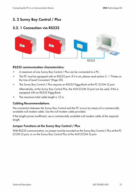
5.2. 1 Connection via RS232
RS232 communication characteristics:• A maximum of one Sunny Boy Control / Plus can be connected to a PC.
• The PC must be equipped with an RS232 port. If it is not, please read section 5. 1 "Notes on the Use of Level Converters" (Page 20).
• The Sunny Boy Control / Plus requires an RS232 Piggy-Back at the PC (COM 2) port.
Alternatively, at the Sunny Boy Control Plus, the AUX (COM 3) port can be used, if this is equipped with an RS232 Piggy-Back.
• The maximum total cable length is 12 m.
Cabling RecommendationsThe connection between the Sunny Boy Control and the PC occurs by means of a commercially available null modem cable. Use the null modem cable provided.
If the length proves insufficient, use a commercially available null modem cable of the required length.
Jumper Functions at the Sunny Boy Control / PlusWith RS232 communication, no jumper must be mounted on the Sunny Boy Control / Plus at the PC (COM 2) port, or on the Sunny Boy Control Plus at the AUX (COM 3) port.
RS232

Connecting the PC to a Communication Device SMA Technologie AG
22 SDC-TEN081450 Technical Description
Wiring Diagram
PC1.
2. Use the null modem cable provided, or a commercially available null modem cable of the required length.
3. Plug the 9-pin D-Sub female connector into a free COM port on your PC.
4. Lay the cable properly so that there is no risk of persons tripping over it.
Sunny Boy Control / Plus5. Plug the 9-pin D-Sub female connector into the port on
the Sunny Boy Control which is equipped with the RS232 interface.
(A) Sunny Boy Control: PC (COM 2)
(B) Sunny Boy Control Plus: PC (COM 2) or AUX
(COM 3)
Jumper6. Remove any jumpers A, B or C which may be plugged,
from the interfaces used.
NOTICE!
Possible damage to the COM interfaces of the Sunny Boy Control / Plus and the PC.
The COM interfaces of both devices could be damaged if the PC is turned on and then the devices are connected to one another.
• Switch off PC
A B

Connecting the PC to a Communication Device SMA Technologie AG
Technical Description SDC-TEN081450 23
5.2. 2 Connection via RS485
RS485 communication characteristics:• Up to 50 Sunny Boy Control / Plus devices can be connected to a PC.
• The PC must be equipped with an RS485 port. If it is not, please read section 5. 1 "Notes on the Use of Level Converters" (Page 20).
• Each Sunny Boy Control requires an RS485 Piggy-Back at the PC (COM 2) port.
Alternatively, at the Sunny Boy Control Plus, the AUX (COM 3) port can be used, if this is equipped with an RS485 Piggy-Back.
• The maximum total cable length is 1200 m.
Cabling RecommendationsThe cable length and quality affect the signal quality. Observe the following indications in order to achieve good signal quality.
• Use metallic D-Sub female connectors. Female connectors made of plastic, or metallized plastic, can cause faulty data transfer.
• For the outdoors, use a communications cable with the following important properties.
- Cross-section: At least 2 x 2 x 0,22 mm2, and at least 2 x 2 x AWG 24
- shielded
- Twisted pair cables
- UV resistant
We recommend the following cable types for the outdoors.
SMA communications cable: COMCAB-OUTxxx*
*Available in the following lengths: xxx = 100 m/200 m/500 m and 1000
Lappkabel cables: UNITRONIC Li2YCYv 2 x 2 x 0.22 mm2
You can use an indoor cable for the outdoors as well, provided you protect it from UV radiation with the proper cable duct.
RS485
Connecting the PC to a Communication Device SMA Technologie AG
24 SDC-TEN081450 Technical Description
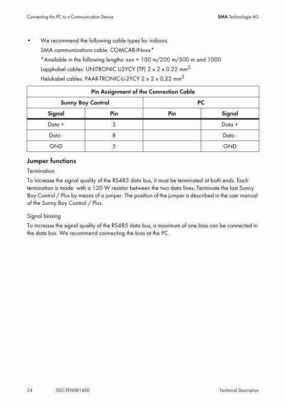
• We recommend the following cable types for indoors.
SMA communications cable: COMCAB-INxxx*
*Available in the following lengths: xxx = 100 m/200 m/500 m and 1000
Lappkabel cables: UNITRONIC Li2YCY (TP) 2 x 2 x 0.22 mm2
Helukabel cables: PAAR-TRONIC-Li-2YCY 2 x 2 x 0,22 mm2
Jumper functionsTermination
To increase the signal quality of the RS485 data bus, it must be terminated at both ends. Each termination is made with a 120 W resistor between the two data lines. Terminate the last Sunny Boy Control / Plus by means of a jumper. The position of the jumper is described in the user manual of the Sunny Boy Control / Plus.
Signal biasing
To increase the signal quality of the RS485 data bus, a maximum of one bias can be connected in the data bus. We recommend connecting the bias at the PC.
Pin Assignment of the Connection Cable
Sunny Boy Control PC
Signal Pin Pin Signal
Data + 3 Data +
Data - 8 Data -
GND 5 GND

Connecting the PC to a Communication Device SMA Technologie AG
Technical Description SDC-TEN081450 25
Wiring Diagram
PC1.
2. Plug the 9-pin D-Sub female connector into a free COM port on your PC.
For the pin assignment of the RS485 connection, please refer to the PC's documentation, or the plug-in card's documentation.
Data+ and Data– leads must be a twisted pair.
3. Shorten the wire of the fourth, unused conductor, so that short circuits cannot arise.
4. Note down the wire color:
Termination5. Only if the PC is at one end of the 485 data bus:
Terminate the end of the cable as described in the instructions for the PC or the plug-in card.
Signal biasing6. Configure the RS485 data bus' bias as
described in the PC's documentation, or the plug-in card's documentation.
7. Lay the cable properly so that there is no risk of persons tripping over it.
NOTICE!
Possible damage to the COM interfaces of the Sunny Boy Control/Plus and the PC.
The COM interfaces of both devices could be damaged if the PC is turned on and then the devices are connected to one another.
• Switch off PC
Data + ____________________
Data - ____________________
GND ____________________

Connecting the PC to a Communication Device SMA Technologie AG
26 SDC-TEN081450 Technical Description
Sunny Boy Control / Plus8. Plug the 9-pin D-Sub female connector into the
port on the Sunny Boy Control which is equipped with the RS485 interface.
(A) Sunny Boy Control: PC (COM 2)
(B) Sunny Boy Control Plus: PC (COM 2) or AUX (COM 3)
9. Connect the PC's Data+ with the Data+ of the Sunny Boy Control / Plus, and so on. The 3 connections should be made directly.
Use listed cable colors.
Termination10. On the last Sunny Boy Control / Plus in the 485
data bus, Jumper A should be plugged into the interface being used.
11. Jumper A must not be plugged into the used interface on any of the other Sunny Boy Control / Plus devices.
12. Remove any jumpers A, B or C which may be plugged, from the interfaces used.
A B
A B

Connecting the PC to a Communication Device SMA Technologie AG
Technical Description SDC-TEN081450 27
5.2. 3 Connection via the Analog Modem NET Piggy-Back
Analog Modem Communication Characteristics• As the connection to the Sunny Boy Control / Plus is established via the telephone network, it
is only ever possible to connect one Sunny Boy Control / Plus with the PC.
• The PC must be equipped with a modem (analog, ISDN with CAPI driver or GSM).
• The Sunny Boy Control / Plus requires an "analog modem" version of the NET Piggy-Back.
Connection1. Connect the PC to the telephone network, as described in the modem instructions.
2. Connect the Sunny Boy Control / Plus to the telephone network, as described in the instructions for the Net Piggy-Back.
3. Use the software provided with the PC operating system to establish the connection between the two devices.
Compatibility with all PC modems available on the market cannot be guaranteed.

Connecting the PC to a Communication Device SMA Technologie AG
28 SDC-TEN081450 Technical Description
5.2. 4 Connection via the ISDN NET Piggy-Back
ISDN Modem Communication Characteristics• As the connection to the Sunny Boy Control / Plus is established via the telephone network, it
is only ever possible to connect one Sunny Boy Control / Plus with the PC.
• The PC must be equipped with an ISDN modem.
• The Sunny Boy Control / Plus requires an "ISDN" version of the NET Piggy-Back.
Connection1. Connect the PC to the telephone network, as described in the modem instructions.
2. Connect the Sunny Boy Control / Plus to the telephone network, as described in the instructions for the Net Piggy-Back.
3. Use the software provided with the PC operating system to establish the connection between the two devices.
Compatibility with all PC modems available on the market cannot be guaranteed.

Connecting the PC to a Communication Device SMA Technologie AG
Technical Description SDC-TEN081450 29
5.2. 5 Connection via the GSM NET Piggy-Back
GSM Modem Communication Characteristics• As the connection to the Sunny Boy Control / Plus is established via the telephone network, it
is only ever possible to connect one Sunny Boy Control / Plus with the PC.
• The PC must be equipped with a modem (analog, ISDN with CAPI driver or GSM).
• The Sunny Boy Control / Plus requires a "GSM" version of the NET Piggy-Back.
Connection1. Connect the PC to the telephone network, as described in the modem instructions.
2. Connect the Sunny Boy Control / Plus to the telephone network, as described in the instructions for the Net Piggy-Back.
3. Use the software provided with the PC operating system to establish the connection between the two devices.
Compatibility with all PC modems available on the market cannot be guaranteed.

Connecting the PC to a Communication Device SMA Technologie AG
30 SDC-TEN081450 Technical Description
5.2. 6 Connection via the Ethernet NET Piggy-Back
Ethernet Network Communication Characteristics• Any number of Sunny Boy Control / Plus devices can be connected to a PC via the Ethernet
network. The only limitation is the capability of the PC, whereby the main memory is the limiting factor.
• A Sunny Boy Control / Plus can be connected directly to a PC.
• The PC must be equipped with an Ethernet network card.
• Each Sunny Boy Control / Plus requires an "Ethernet" version of the NET Piggy-Back.
Cabling RecommendationsThe cable length and quality can adversely affect the signal quality. To achieve good results, observe the following instructions.
• For the connection to a hub or router, you require a patch cable.
For the direct connection to a PC, you require a crossover cable.
• Use high quality cable, at least category 5 (SFTP Cat 5) or higher shielded twisted pair cable.
• The maximum permitted cable length for Ethernet cable is 100 m.
Connection to an Ethernet Network1. Connect the PC to the network as described in the Ethernet network card's user manual.
2. Connect the Sunny Boy Control / Plus to the telephone network, as described in the instructions for the Net Piggy-Back.
Direct Connection to a Single PC1. Plug one end of the crossover cable into the PC's Ethernet network card.
2. Plug the other end of the Ethernet network cable into the NET socket of the Sunny Boy Control / Plus.
3. Lay the cable properly so that there is no risk of persons tripping over it.
Router or hub

Connecting the PC to a Communication Device SMA Technologie AG
Technical Description SDC-TEN081450 31
5. 3 Sunny Beam
5.3. 1 Connection via USB
USB Communication Characteristics• A maximum of one Sunny Beam can be connected to a PC.
• The PC must be equipped with a USB port.
• The maximum total cable length is 3 m.
Connection1. Connect the Sunny Beam to the PC as described in the Sunny Beam manual.
USB

Installation SMA Technologie AG
32 SDC-TEN081450 Technical Description
6 InstallationYou can download Sunny Data Control from the download area at www.SMA.de or you can order it as a CD.
6. 1 Installing Sunny Data Control1. Switch on your PC and wait until the
operating system has booted up completely.
2. Close any Windows programs which may be open.
3. Start the Sunny Data Control installation program. The Sunny Data Control installation window opens (see figure to the right).
4. Follow the installation program's instructions.
SDC agentYou need the SDC Agent only if you also intend to use Sunny Data Control for the online presentation of your PV plant.
You do not need the SDC Agent for Sunny Portal.
5. Place a check mark next to "SDC Agent" in order to install it as well.
6. Once the installation is finished, you can launch Sunny Data Control.

Sunny Data Control User Interface SMA Technologie AG
Technical Description SDC-TEN081450 33
7 Sunny Data Control User InterfaceThe Sunny Data Control user interface comprises three areas:
• (A) Menu Area
In the menu area you can access and use various Sunny Data Control functions by using the menu bar. Using the symbols you can open the corresponding menu directly.
• (B) Plant diagram
The plant selected is displayed, along with its devices, which you have detected with Sunny Data Control.
• (C) Display Area
In the display area you can display different views by selecting the appropriate tab.
- Overview
- Spot values (device overview)
- Parameter
- Channel recording (is shown once the devices have been detected).
B C
A

Sunny Data Control User Interface SMA Technologie AG
34 SDC-TEN081450 Technical Description
7. 1 Menu AreaThe menu area comprises the menu bar (A1) and the icon bar (A2).
The most commonly used menus are also included as icons on the icon bar (A2), so they can be accessed quickly.
(A1) Menu barThe menu bar comprises six main menus:
• File
• Connection
• Spot values
• Continuous data recording.
Is only shown if there are yet no devices listed in the plant diagram, or if only one inverter is connected directly to the PC.
• Options
• Extras
• ? (Manual, Information)
(A2) Icon barThe icon bar is made up of icons representing the menu items most commonly used.
• Plant
Also accessible in the menu area via "Options / Choose Plant".
• Search
Also accessible in the menu area via "Options / Device detection".
• Record or save
Record is shown if there are yet no devices listed on the plant diagram (no devices have been detected) or if only one inverter is connected directly to the PC.
Save is shown as soon as there are devices listed on the plant diagram (devices have been detected).
• Show
• Settings
Also accessible in the menu area via "Options/Settings".
A1
A2

Sunny Data Control User Interface SMA Technologie AG
Technical Description SDC-TEN081450 35
7. 2 Plant treeThe plant selected is displayed, along with its devices, which you have detected with Sunny Data Control.
Using the plant diagram menu here (see illustration) you can, for example, access information about the selected device or delete it and add, arrange or substitute devices.
Some of the actions which you can select in the plant tree menu apply to the currently selected device, while other actions apply to all devices.
If you call up the plant tree menu via the icon, you must first highlight the respective device by clicking on the device's name.
Expanding and Collapsing the Plant TreeBy clicking on the nodes (+/- symbols), you can expand and collapse parts of the plant diagram. This function facilitates the overview of a plant with many devices.

Sunny Data Control User Interface SMA Technologie AG
36 SDC-TEN081450 Technical Description
7. 3 Display AreaIn the display area you can call up different pages by using the tabs (A).
- Overview
- Spot values (device overview)
- Parameter
- Channel recording (is shown once the devices have been detected).
When the "Spot values" page is shown, you can call up the task menu (B).
You can open up the task menu (B) by clicking on the icon to the right, or by right-clicking on the respective device's field. Some of the actions you can choose in the plant diagram menu apply only to the device selected and others apply to all.
B
A

Initial Settings SMA Technologie AG
Technical Description SDC-TEN081450 37
8 Initial Settings
8. 1 Creating PlantsBy default, a plant with the name "My Plant" is always created automatically by Sunny Data Control during installation. You can change the plant name which is displayed in Sunny Data Control, create additional plants, or delete plants.
Sunny Data Control can only display one plant at a time (current plant). If you manage several plants, you must first load each respective plant (see section 8. 2 "Loading a Plant" (Page 38)).
Detected devices and settings, such as the communication connection or parameters, always refer to the respective plant, and are saved as settings for the respective plant.
8.1. 1 Changing Plant Names, Creating / Deleting PlantsChanging the Plant Name1. "Options/Choose plant"
The "PV Plant" window opens.
2. Select "My PV plant".
3. Click on <Rename>. The name of the selected plant can now be written over.
4. Type in the desired name for the plant.
5. Click on <Close>.

Initial Settings SMA Technologie AG
38 SDC-TEN081450 Technical Description
Create new plant1. Select "Options/Choose plant".
The "PV Plant" window opens.
2. Click on <New>.
3. Type in the desired name for the plant.
4. Click on <Close>.
Deleting Plants
1. Select "Options/Choose plant".
The "PV Plant" window opens.
2. Select the plant to be deleted.
3. If the selected plant, along with all settings and detected devices, is to be deleted immediately, click on <Delete>.
4. Click on <Close>.
8. 2 Loading a PlantIf you have created more than one plant, you must first load the plant which you wish to edit or display. Sunny Data Control can only display one plant at a time (current plant).
1. Select "Options/Choose plant".
The "PV Plant" window opens.
2. Select the plant to be loaded.
3. Click on <Load>.
Directions for deletion
If you delete a plant, the entire plant is deleted, along with all settings and detected devices! The saved Excel and CSV files are retained.

Initial Settings SMA Technologie AG
Technical Description SDC-TEN081450 39
8. 3 Setting the Communication ConnectionOne must set the connection in Sunny Data Control according to the type of connection to the PC which has been chosen.
The communication connection setting always refers to the current plant, and can be set differently for each plant.
In Sunny Data Control, you can set the connections listed below, which are described in the sections which follow.
• Bluetooth
See chapter 8.3. 1 "Bluetooth" (Page 39)
• COM1, 2, 3 etc.
(Your PC's COM ports are listed here: COM 1 , COM 2 , etc.)
See chapter 8.3. 2 "COM1 – COM255" (Page 43)
• Modem
(the type of modem installed at your PC is displayed here)
See chapter 8.3. 3 "Modem" (Page 44)
• Network
See chapter 8.3. 4 "Network" (Page 45)
• Sunny Beam (USB)
See chapter 8.3. 5 "Sunny Beam (USB)" (Page 47)
8.3. 1 Bluetooth
Requirements• PC or laptop with integrated Bluetooth (range of usually only up to 10 m).
Alternative: USB Bluetooth stick (range of Class 1 Bluetooth stick is of up to 100 m).
• A Bluetooth ID of 1 or greater must be set at the inverters.
- ID = 1: Inverters cannot be networked, only inverters within reception range will be detected.
- ID > 1: Inverters are networked, allowing all networked inverters to be detected.
Notice regarding Bluetooth stick software.
Do not install the software included with the Bluetooth stick for the time being.

Initial Settings SMA Technologie AG
40 SDC-TEN081450 Technical Description
Commissioning of Bluetooth communications.1. Close the Sunny Data Control.
2. If the Bluetooth capability integrated into the PC is not to be used, disconnect it as described in the PC instructions.
3. Plug the Bluetooth stick into the PC. Do not install the software included with the Bluetooth stick for the time being.
The PC will check to see whether the Bluetooth stick can be installed automatically, and carries out one of the following actions:
• Automatic installation begins, the PC installs the Bluetooth stick and reports that the new hardware can be used. No CD is needed.
- Continue with step 4.
• The Hardware Assistant window opens, because installation requires a CD.
- Choose "No, not this time". Choose <continue>.
- Insert the CD included with the Bluetooth stick.
- Choose "Install software from a list or a specific source (advanced user)".
- Choose <continue>. The Bluetooh stick will be installed.
- Search for devices.
- The Bluetooth software shows the inverters' "Friendly names". For example: SMA0003dSN: 2100000439 SN2100000439. The Bluetooth ID is displayed after "SMA" (here: SMA0003 is ID 3).
- Choose a device which has the desired Bluetooth ID.
- Set up the virtual COM port as described in the Bluetooth stick manual. The virtual COM port will be set up for the chosen ID.
- Record or note the number of the virtual COM port set up. If the Bluetooth environment is to have an "outgoing" as well as an "incoming" COM port, record or note the number of the incoming COM port.

Initial Settings SMA Technologie AG
Technical Description SDC-TEN081450 41
- If the Bluetooth stick software allows it, configure the settings in such a way that a connection is made only after the application starts.
- Continue with step 4.
4. Start Sunny Data Control.
5. Click on on the "Settings" icon.
The "Settings" window opens.
6. Select "Communication".
7. Choose "Bluetooth" from the drop-down list "Connection via".
8. Click on <Settings>.
9. Click on <Change>.
The window "Choice of Bluetooth connection" opens.

Initial Settings SMA Technologie AG
42 SDC-TEN081450 Technical Description
10. Choose the appropriate procedure according to the type of Bluetooth installation carried out.
11. Detect devices as described in chapter 8. 4 "Detecting Devices" (Page 49).
Installation was possible without a CD. Installation was only possible with a CD.
• Choose "Bluetooth Network IDs" or "Individual Bluetooth devices" (point-to-point connection) from the "Type of display" drop-down menu.
• Click on <Search>.
The Bluetooth IDs of detected devices are searched for and listed.
• Choose the Bluetooth ID set at the inverter and click on <Ok>.
• Close the window with <Ok>.
• Choose "Bluetooth COM ports" from the "Display type" drop-down menu.
• Choose the virtual COM-Port which was set up and click on <Ok>.
• Close the window with <Ok>.

Initial Settings SMA Technologie AG
Technical Description SDC-TEN081450 43
8.3. 2 COM1 – COM2551. Choose "Options / Settings"
The "Settings" window opens.
2. Choose "Communication".
3. In the drop-down list "Connection by", select the COM port via which the Sunny Boy Control is connected to your PC. The COM ports are labeled on your PC (1, 2, 3, etc.).
4. Click on <Settings>.
The connection settings window opens.
5. In the drop-down menu "Media type" choose the type of communication between the Sunny Boy Control and the PC.
Notice regarding the FIFO buffer with RS485.
When using RS485 switch off the serial interfaces' FIFO buffers, as described in the operating system manual.

Initial Settings SMA Technologie AG
44 SDC-TEN081450 Technical Description
Bits per second (Baudrate)6. In the "Bits per second:" drop-down list, select the Baudrate.
- In the case of a connection via the USB service interface: 1200 Bits per second.
- If the Sunny Boy Control is connected to the PC via RS232, with a cable length under 15 m: 19,200 Bits per second.
7. Click on <Ok>.
Transport ProtocolClicking on <More>, the drop-down menu for the transport protocol is shown.
You can leave the preset transport protocol "SMANet + SunnyNet (autom.)" as the setting. Further details are described in chapter 8.3. 6 "Setting the Transport Protocol" (Page 48).
8. Click on <Ok>.
9. Detect devices as described in chapter 8. 4 "Detecting Devices" (Page 49).
8.3. 3 Modem1. Choose "Options / Settings"
The "Settings" window opens.
2. Select "Communication".
3. Choose "Modem" from the drop-down menu "Connection via".
4. Click on <Settings>.
5. Enter the telephone number.
6. In the "Using transport protocol" drop-down list, select the appropriate transport protocol for the connected device, as described in section 8.3. 6 "Setting the Transport Protocol" (Page 48).
7. Click on <Ok>.
8. Detect devices as described in chapter 8. 4 "Detecting Devices" (Page 49).

Initial Settings SMA Technologie AG
Technical Description SDC-TEN081450 45
8.3. 4 Network1. Choose "Options / Settings"
The "Settings" window opens.
2. Select "Communication".
3. Choose "Network" from the drop-down list "Connection via".
4. Click on <Settings>.
The network settings window opens.
Local Network5. If you wish to detect all devices which are connected to your local network, check "Access to
all devices in the local network..." .
6. If you wish to detect additional devices, click on <Add>.
The window for configuration of a new connection opens.
7. In the field, "IP address or DNS name" enter the IP address or the DNS name of the device to be detected.
The default address of the Sunny Boy Control is: 10.170.170.

Initial Settings SMA Technologie AG
46 SDC-TEN081450 Technical Description
8. Click on <Ok>.
The IP address or DNS name of the device is displayed.
RAS ConnectionYou can access an external modem (if access to it has been enabled for you) via an RAS connection, in order to query the data from Sunny Data Control on this connection. If you wish to access an external modem from your PC, the RAS service must be installed and configured on your PC, and on the PC which you wish to access.
1. Check the field "Use RAS".
The window for configuration of the RAS connection opens.
2. In the field "Connection name" enter a descriptive name for the connection which would make it easily recongizable, for example, the name of the plant or a family name.
3. In the field "Telephone number", enter the telephone number of the modem (connection).

Initial Settings SMA Technologie AG
Technical Description SDC-TEN081450 47
4. Choose the connection from the drop-down menu "Connection via".
5. In the field "Username", enter username of the owner of the connection.
6. In the field "Password" enter the password given by the owner of the connection.
7. Click on <Test the connection> to test the connection settings.
8. Click on <Save> to save the settings. The new connection is in the field "Telephone entries".
9. Click on <Apply>. The "Current device connections" window is displayed once more.
10. In the "Using transport protocol" drop-down list, select the appropriate transport protocol for the connected device, as described in section 8.3. 6 "Setting the Transport Protocol" (Page 48).
11. Click on <Ok>.
12. Detect devices as described in chapter 8. 4 "Detecting Devices" (Page 49).
8.3. 5 Sunny Beam (USB)1. Choose "Options / Settings"
The "Settings" window opens.
2. Select "Communication".
3. Choose "Sunny Beam" from the drop-down list "Connection via".
4. If you wish to see which Sunny Beam devices are already detected, click on <Settings>.
5. Click on <Ok>.
6. Detect devices as described in chapter 8. 4 "Detecting Devices" (Page 49).

Initial Settings SMA Technologie AG
48 SDC-TEN081450 Technical Description
8.3. 6 Setting the Transport Protocol1. Choose "Options / Settings"
The "Settings" window opens.
The transport protocol depends on the type of device connected to the PC.
If you are unsure which transport protocol to set, select "SMANet + SunnyNet (auto)". Sunny Data Control then automatically searches for the correct transport protocol.
Communication Devices• Sunny Boy Control / Plus
- The Sunny Boy Control can operate with either transport protocol. The default setting in the Sunny Boy Control is SMA-Net. Select the transport protocol which is set in your Sunny Boy Control.
• Sunny Beam
- Select "SMANet".
Inverter• SMA-Net
- Sunny Boys of type SWR, version BFR 8.22, or later
- All Sunny Boys of type SB
- All Sunny Mini Centrals
- All Sunny Centrals
• Sunny-Net
- Sunny Boys of type SWR prior to version BFR 8.22

Initial Settings SMA Technologie AG
Technical Description SDC-TEN081450 49
8. 4 Detecting DevicesBy default, Sunny Data Control detects the following communication devices: Sunny Beam without inverters, Sunny Boy Control with the inverters to which it is connected, and an inverter connected directly to the PC. If necessary, you can narrow the scope of detection, as described in section 8.4. 1 "Narrowing the Scope of Device Detection" (Page 50).
1. Choose "Options/Device detection" or click on the icon "Search".
The "Searching for plant devices" window opens.
2. Enter the number of devices to be searched for.
3. Click on <Ok>.
The detection process starts. The devices are searched for.
4. Wait for the search to end.
The window closes when the search has ended (see illustration above).
The devices detected are listed on the plant diagram.

Initial Settings SMA Technologie AG
50 SDC-TEN081450 Technical Description
8.4. 1 Narrowing the Scope of Device DetectionThe scope of device detection can be limited to the communication devices and the inverters connected to them, or to an inverter connected directly to the PC.
1. Choose "Options / Settings"
The "Settings" window opens.
2. Select "Misc“.
3. In the area "Device detection mode, searching for" choose the types of device to be detected in the search.
4. Click on <Ok>.
5. Start the device detection process, as described in section 8. 4 "Detecting Devices" (Page 49).

Setting Parameters (Installer) SMA Technologie AG
Technical Description SDC-TEN081450 51
9 Setting Parameters (Installer)Sunny Data Control makes it possible to set parameters for inverters and for the Sunny Boy Control, in order to specify operating modes for individual devices. The type and scope of the displayed parameters depend on the security level.
If you are logged in as an installer, you can set more parameters. The security level is set via the menu item "Extras / Security Level". See section 13. 10 "Changing the Security Level (Installer Password)." (Page 147).
The "Parameters" window shows the parameter list of the device currently selected from the plant diagram. Some parameters serve merely as information regarding the factory settings, whereas others are adjustable.
1. From the plant diagram, choose the device the parameters of which should be edited.
2. Open the tab "Parameters".
The device's current parameter list is queried and listed.
Only the channel names in black type can be changed.
DANGER!Death hazard due to changes in the inverter's internal safety specifications.
Unauthorized changes to the SMA grid guard parameters cancel the operating permit.
• Changes to the SMA grid guard parameters are to be made only with the express permission of the grid operator.
Grid guard parameters in SB4000TL-20/5000TL-20 via Bluetooth.
If the SB4000TL-20/5000TL-20 is connected with Sunny Data Control via Bluetooth, the SMA grid guard parameter can be set using the padlock icon at the top right on the "Parameters" page.

Setting Parameters (Installer) SMA Technologie AG
52 SDC-TEN081450 Technical Description
3. Click on the channel to be edited.
The "New parameter value" window opens.
4. Enter the new parameter value or choose it (this depends on the parameter. The changes are not applied immediately. The parameter changed is marked for transfer with a blue point and bold type.
5. If the new parameter value is to be applied to all devices of the same type, check the field "For all devices with same type".
6. Click on <Ok>.
The channel changed is marked.
Accept changes7. To apply all changes click on <Apply> on the lower edge of the screen. If the changes are
accepted by all devices successfully, the markings (blue point, bold type) are deleted.
• Edit: Edit the selected channel (or double click).
• Update: Updates the channel list displayed.
• Apply: Applies all changes and sets the parameters in the devices.
• Abort: No changes are made.

Displaying Data SMA Technologie AG
Technical Description SDC-TEN081450 53
10 Displaying DataVarious options are at your disposal for the display of current operating data. In order to manage the copious amounts of data which arise, you can combine these options according to the size of your plant and your display requirements for clarity and informative value.
The following display options are available:
• (A) Device overview on the page "Spot values" with individual device fields (A1).
• (B) Individual device information
• (C) Total overview
You can assign each individual display mode to each selected measuring channel. In so doing, it is also possible to assign several display modes to the same channel.
The following sections describe the individual steps necessary for the display of the present operating data.
A
B C
A1

Displaying Data SMA Technologie AG
54 SDC-TEN081450 Technical Description
10. 1 Creating a Device OverviewThe page "Spot values", on which the device overview is shown, provides a quick and informative display of your entire plant's current operative state. You can see your plant's devices and their operative states at a glance.
The "Spot values" page is subdivided into fields (see figure below). In each field a device can be displayed.
You can create and save several device overviews for each plant. This function is useful, for example, with plants which include many devices, because it provides a clearer overview, and different data views can be saved (see section 10. 8 "Managing the Device Overviews" (Page 67)).
1. "Drag and drop" the device from the plant diagram onto the desired field on which the device should be displayed.
Only one device per field, and each device only once.
You can only drag each device into the device overview once. You can only drop a device into an empty field.

Displaying Data SMA Technologie AG
Technical Description SDC-TEN081450 55
2. If you have dragged a Sunny Boy Control into a field, a prompt window opens.
- Klick on <yes> to add all inverters corresponding to Sunny Boy Control as well.
- To add only the Sunny Boy control, click on <No>.
Depending on whether you clicked <Yes> or <No> in the prompt window, either just the Sunny Boy Control, or the Sunny Boy Control with all of its inverters, are added to the "Spot values" page.
Repositioning the Fields3. Drag and drop occupied fields onto the desired empty fields.
This enables you to represent the actual structure of your plant pictorially in the overview display or to combine several devices in groups.
Displaying Data SMA Technologie AG
56 SDC-TEN081450 Technical Description
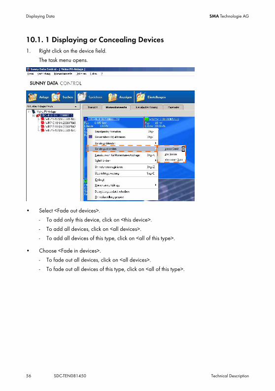
10.1. 1 Displaying or Concealing Devices1. Right click on the device field.
The task menu opens.
• Select <Fade out devices>.
- To add only this device, click on <this device>.
- To add all devices, click on <all devices>.
- To add all devices of this type, click on <all of this type>.
• Choose <Fade in devices>.
- To fade out all devices, click on <all devices>.
- To fade out all devices of this type, click on <all of this type>.

Displaying Data SMA Technologie AG
Technical Description SDC-TEN081450 57
10.1. 2 Arranging the FieldsYou can change the vertical and horizontal arrangement of the fields in the device overview.
1. Choose "Options / Settings"
2. Select "Spotvalue Request / Arrangement".
3. In the area "Arrangement of devices horizontally / vertically", enter the number of fields that you wish to have displayed.
Maximum number of fields: 100 x 100.
Minimum number of fields: 1 x 1.
If you wish to increase the number of fields to such an extent that the devices which are already displayed will no longer have sufficient space to be fully displayed in the new device overview, the adjustment of scale is ignored.
10.1. 3 Show or Hide the Grid Lines1. Choose "Options / Settings"
2. Select "Spotvalue Request / Arrangement".
3. In the "Grid lines" area, add or remove the check mark in the "visible" check box.
10.1. 4 Setting the Data Query SequenceYou can set the direction in which Sunny Data Control scans the devices as vertical or horizontal.
1. Choose "Options / Settings"
2. Select "Spotvalue Request / Arrangement".
3. Set the scanning direction in the drop-down menu "Scanning direction".
10.1. 5 Maximizing the Device Overview (Online Display)You can display the device overview in an enlarged format, covering the entire screen.
1. Open the "Spotvalues" tab.
2. Right click on the page.
The task menu opens.
3. Select "Maximize online display“.
The device overview is shown in an enlarged format, covering the entire screen. The plant diagram and the menu bar are concealed.
4. To reduce the size of the display again, right click on the page and choose "Minimize online page".

Displaying Data SMA Technologie AG
58 SDC-TEN081450 Technical Description
10. 2 Choose the channels for spot value readings.For each device, you can set up which spot values are to be displayed on the page "Spot values" on the device field (A) and in the individual device information (B).
You can retrieve the individual device information by right-clicking on the desired device on the page "Spot values", and choosing "individual device information (see also chapter10. 6 "Accessing Individual Device Information" (Page 63)).
1. Right click on the device field on the page "Spot values".
The task menu opens.
2. Select "Channel selection for Spot value scan"
The window for setting the selected device's channels opens.
3. Under "Channel selection is valid for", select whether you wish to set the channel selection for the selected device only, or for all devices of a particular type.
4. Use the arrow buttons to add or remove the desired channels for the respective spot value queries. To select several channels, hold down the control key.
A
B
Displaying Data SMA Technologie AG
Technical Description SDC-TEN081450 59
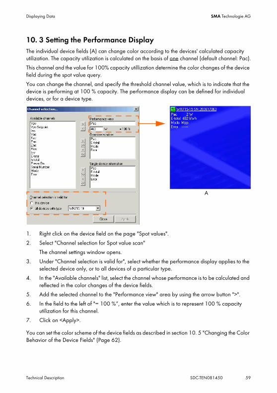
10. 3 Setting the Performance DisplayThe individual device fields (A) can change color according to the devices' calculated capacity utilization. The capacity utilization is calculated on the basis of one channel (default channel: Pac).
This channel and the value for 100% capacity utillization determine the color changes of the device field during the spot value query.
You can change the channel, and specify the threshold channel value, which is to indicate that the device is performing at 100 % capacity. The performance display can be defined for individual devices, or for a device type.
1. Right click on the device field on the page "Spot values".
2. Select "Channel selection for Spot value scan"
The channel settings window opens.
3. Under "Channel selection is valid for", select whether the performance display applies to the selected device only, or to all devices of a particular type.
4. In the "Available channels" list, select the channel whose performance is to be calculated and reflected in the color changes of the device fields.
5. Add the selected channel to the "Performance view" area by using the arrow button ">".
6. In the field to the left of "= 100 %“, enter the value which is to represent 100 % capacity utilization for this channel.
7. Click on <Apply>.
You can set the color scheme of the device fields as described in section 10. 5 "Changing the Color Behavior of the Device Fields" (Page 62).
A
Displaying Data SMA Technologie AG
60 SDC-TEN081450 Technical Description
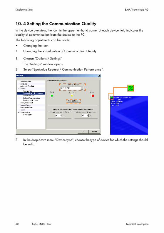
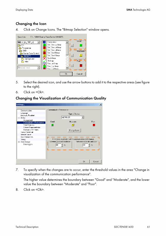
10. 4 Setting the Communication QualityIn the device overview, the icon in the upper left-hand corner of each device field indicates the quality of communication from the device to the PC.
The following adjustments can be made:
• Changing the Icon
• Changing the Visualization of Communication Quality
1. Choose "Options / Settings"
The "Settings" window opens.
2. Select "Spotvalue Request / Communication Performance“.
3. In the drop-down menu "Device type", choose the type of device for which the settings should be valid.
Displaying Data SMA Technologie AG
Technical Description SDC-TEN081450 61
Changing the Icon4. Click on Change Icons. The "Bitmap Selection" window opens.
5. Select the desired icon, and use the arrow buttons to add it to the respective areas (see figure to the right).
6. Click on <Ok>.
Changing the Visualization of Communication Quality
7. To specify when the changes are to occur, enter the threshold values in the area "Change in visualization of the communication performance".
The higher value determines the boundary between "Good" and "Moderate", and the lower value the boundary between "Moderate" and "Poor".
8. Click on <Ok>.

Displaying Data SMA Technologie AG
62 SDC-TEN081450 Technical Description
10. 5 Changing the Color Behavior of the Device Fields1. Choose "Options / Settings"
2. Select "Spotvalue Request / Colored Representation".
3. Click on <Load Scale>.
The "Load Palette for Performance Display" window opens.
4. Select a color palette from the list, and click on <Open>.
To learn how to create your own color palette, see section 13. 6 "Creating a Color Palette for Device Fields" (Page 142).
Changing the Text ColorYou can define which of the displayed text colors is to be used until which threshold background color is reached.
5. Move separation mark (see figure below)
Displaying Data SMA Technologie AG
Technical Description SDC-TEN081450 63
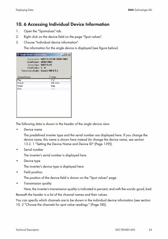
10. 6 Accessing Individual Device Information1. Open the "Spotvalues" tab.
2. Right click on the device field on the page "Spot values".
3. Choose "Individual device information".
The information for the single device is displayed (see figure below).
The following data is shown in the header of the single device view:
• Device name
The predefined inverter type and the serial number are displayed here. If you change the device name, this name is shown here instead (to change the device name, see section 13.2. 1 "Setting the Device Name and Device ID" (Page 139)).
• Serial number
The inverter's serial number is displayed here.
• Device type
The inverter's device type is displayed here.
• Field position.
The position of the device field is shown on the "Spot values" page.
• Transmission quality
Here, the inverter's transmission quality is indicated in percent, and with the words: good, bad.
Beneath the header is a list of the channel names and their values.
You can specify which channels are to be shown in the individual device information (see section 10. 2 "Choose the channels for spot value readings." (Page 58)).

Displaying Data SMA Technologie AG
64 SDC-TEN081450 Technical Description
10. 7 Configuring the Total OverviewThe total overview provides you with a quick overview of your plant's present performance data.
The total overview is updated cyclically.
The following information is displayed:
• Total output at present (Pac)
• Total yield (E-total)
• Energy produced today (E-Today)
This can only be selected if a Sunny Boy Control is also selected as device type for the total overview.
Selecting Device TypesDevices are only included in the total overview computation if they are shown on the "Spot values" page and only if their device type has been selected for the total overview.
1. Choose "Options / Settings"
2. Select "Spot value Request / Total Overview".
3. Click on <Change> to select the device types for the computation of the total overview.
Displaying Data SMA Technologie AG
Technical Description SDC-TEN081450 65
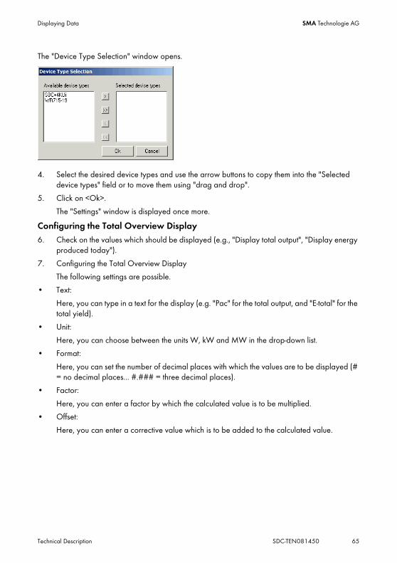
The "Device Type Selection" window opens.
4. Select the desired device types and use the arrow buttons to copy them into the "Selected device types" field or to move them using "drag and drop".
5. Click on <Ok>.
The "Settings" window is displayed once more.
Configuring the Total Overview Display6. Check on the values which should be displayed (e.g., "Display total output", "Display energy
produced today").
7. Configuring the Total Overview Display
The following settings are possible.
• Text:
Here, you can type in a text for the display (e.g. "Pac" for the total output, and "E-total" for the total yield).
• Unit:
Here, you can choose between the units W, kW and MW in the drop-down list.
• Format:
Here, you can set the number of decimal places with which the values are to be displayed (# = no decimal places... #.### = three decimal places).
• Factor:
Here, you can enter a factor by which the calculated value is to be multiplied.
• Offset:
Here, you can enter a corrective value which is to be added to the calculated value.

Displaying Data SMA Technologie AG
66 SDC-TEN081450 Technical Description
8. Click on <Ok>.
Activate Total Overview9. Select "Spot values / Activate Total Overview".
Alternatively, click on the "Spot values" page and choose Select "Spotvalues / Activate Total Overview".
The total overview is shown.
You can make the window bigger or smaller. The font size adapts automatically.
Deactivate the total overviewIf you wish to deactivate the total overview, simply close the total overview window.

Displaying Data SMA Technologie AG
Technical Description SDC-TEN081450 67
10. 8 Managing the Device OverviewsYou can create several device overviews for each plant ("Spot values" page). The configuration data, for example, the devices' channel selections, the size and arrangement of the overview window, etc., are saved together with the device overview.
The task of completely setting up an overview window with several devices can in some cases be highly complex. To ensure that this effort only needs to be made once, Sunny Data Control provides you with the option of managing different device overviews.
As a preset, the overview named "Online00" is created. See figure below.
10.8. 1 Managing the Device Overviews1. Select "Spotvalues / Overview Management".
The "Overview Management" window opens.
All device overviews which have already been created are shown in the "Available Overviews" list. The device overview "Online00" is the default, and can be renamed.
You can load, save, rename and delete device overviews here.

Displaying Data SMA Technologie AG
68 SDC-TEN081450 Technical Description
10. 9 Activating / Deactivating Spot Value QueryingYou can activate and deactivate the querying of spot values if at least one device is displayed in the device overview.
1. Choose "Spot values/Spot value querying".
2. Select "Activate" or "Deactivate".
If spot value querying is active, the icon and border of the currently queried device will flash.
During spot value querying, the text shown below is displayed in the bar at the lower edge of the screen.

Managing Data and Saving Data Locally SMA Technologie AG
Technical Description SDC-TEN081450 69
11 Managing Data and Saving Data LocallyWith Sunny Data Control, plant data can be saved in Excel and/or CSV formats. The following sections describe the storage of data in Excel format and in CSV format. If an inverter is connected directly to the PC, the data can only be saved as CSV data (SUO format, SMA-Sunny Online). See chapter 11. 4 "Direct Data Acquisition from an Inverter" (Page 77).
11. 1 Reading Out and Saving Data from Sunny BeamIn order to display the essential key data of a PV system, Sunny Beam has been developed as a cordless tabletop device. Initially, there were no plans for the archiving of data. Thus, as indicated below, the subsequent built-in possibility to record data using Sunny Data Control and Sunny Portal is limited.
Data Archiving with Sunny Data ControlWith the Sunny Beam, the data gathered from the entire plant during one month can be archived, but not data from the individual inverters. As the values are only stored in Sunny Beam for one month, you must read out the data with Sunny Data Control once a month.
Furthermore, Sunny Beam only saves the daily power output (Pac) for the present day. Once a new day begins, the previous day's Pac data is erased. Thus, Pac data must be read out every evening.
Archiving Data with Sunny PortalWith Sunny Data Control, the above-mentioned data can be transferred over to the Sunny Portal.
Because the E-total value can not be recorded using Sunny Beam, the use of this data with Sunny Portal is restricted. Nevertheless, this is indispensable for some views using Sunny Portal. For this reason, it only makes sense to graphically present Sunny Portal's daily energy values (E-day), the avoided CO2 emissions and the yield (EUR) as a monthly overview.
The visualization of the daily output (Pac) is possible. Nevertheless, as already mentioned above, the data must be read out nightly.
Data Interval
E-day: read out once a month
Yield (EUR): read out once a month
CO2 avoided: read out once a month
Data Interval
Pac: read out every evening
(limited utilizability)

Managing Data and Saving Data Locally SMA Technologie AG
70 SDC-TEN081450 Technical Description
11. 2 Saving Data in Excel FormatStorage of data in Excel format is the default option, and can be activated and deactivated. The data is saved in the directory in which Sunny Data Control was installed. The default directory is "C:\Programs\SMA\Sunny Data Control\Plants“.
If you wish to save the data in Excel format, all that remains to be done is to select the channels which are to be recorded. This is explained in section 11. 5 "Setting up Sunny Boy Control Channel Recording" (Page 81).
Activating or Deactivating Data Storage in Excel Format1. Choose "Options / Settings"
2. Select "Data Storage“.
3. Check on the field to the left of Excel, or remove the check, in order to switch the data storage in Excel format on or off.
4. Click on <Ok>.

Managing Data and Saving Data Locally SMA Technologie AG
Technical Description SDC-TEN081450 71
11. 3 Saving Data in CSV FormatFor storage of data in CSV format, various templates are at your disposal. The CSV files can also be created in a user-defined manner. The following settings are user-definable:
• Storage location
• File names
• Number of rows of measured values
• Line break format
• Delimiter symbol (cell separator)
• Storage of measured values (which channel in which row, etc.)
• Time stamp from time of measurement
11.3. 1 Creating a New CSV Type
1. Choose "Options / Settings"
2. Select "Data Storage“.
3. Click on <+> to set a new CSV type.
Instructions on changing a CSV-Type.
The settings for a created CSV type can no longer be altered once the first data have been read and saved.

Managing Data and Saving Data Locally SMA Technologie AG
72 SDC-TEN081450 Technical Description
The window for configuration of a new CSV type opens.
4. Type the desired name for the CSV type into the "Name" field.
5. The CSV data is stored in the following directory as a preset/default.
C:\Documents and Settings\“Name of User“\Application Data\SMA\Sunny Data Control\Plants\“Plant name“\“CSV_1 etc.“
This directory is user-specific, and is set up automatically upon creation of a new CSV type. If you wish to select a different directory, click on the folder icon.
Selecting a Template6. Select a template in the "Template" field.
The templates have the following properties:
- SMA standard format: Everything freely selectable, except for the file's column header.
- SMA-Sunny Online (SUO): Column header as in Excel / SUO files, predefined values, no column selection. Column header as in Sunny Data.
- No column header:No column header, predefined values, manual column selection.
- User-defined: Everything freely selectable.

Managing Data and Saving Data Locally SMA Technologie AG
Technical Description SDC-TEN081450 73
Insert ModeDepending on which template you have selected, you can specify the method of insertion.
• fixed
The "fixed" mode is used when only certain channels are to be saved.
The columns are specified by the user. The selection of columns is set via the <Select columns> button, as described in the next step.
• XY Diagram
In "autotinsert" mode, the channels which are set under "Channel recording" are saved.The next section describes how to set the channels for channel recording. See section 11. 5 "Setting up Sunny Boy Control Channel Recording" (Page 81). The columns are inserted automatically.
7. In the "Insert mode" field, select one of the two modes for writing measured values to CSV files.
Selecting ColumnsDepending on which template you have selected, you can now select the columns.
8. Click on <Select columns...>.
The "Select columns" window opens.
9. In the "Column type" drop-down menu, choose a column type.
There are four column types:
- <empty> = column remains empty in the CSV file.
- Channel = allocation occurs via selection of a channel.
- Text = the entered text is written in the column.
- Timestamp = the date pattern from the combination field (combo box) is written as an absolute date.

Managing Data and Saving Data Locally SMA Technologie AG
74 SDC-TEN081450 Technical Description
You can insert a new column above a highlighted column with <Insert>.
With <Delete>, you can delete the highlighted column.
With <New>, you can add a new column beneath all the other columns.
The order of the rows in the table can be changed using "drag and drop".
10. Set up the column types as desired.
11. Click on <Apply>.
The window for setting the CSV type is shown again.
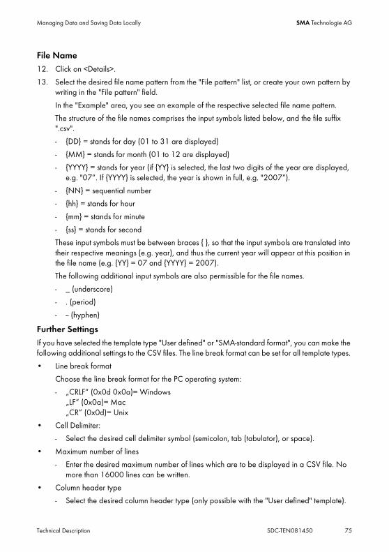
Managing Data and Saving Data Locally SMA Technologie AG
Technical Description SDC-TEN081450 75
File Name12. Click on <Details>.
13. Select the desired file name pattern from the "File pattern" list, or create your own pattern by writing in the "File pattern" field.
In the "Example" area, you see an example of the respective selected file name pattern.
The structure of the file names comprises the input symbols listed below, and the file suffix ".csv".
- {DD} = stands for day (01 to 31 are displayed)
- {MM} = stands for month (01 to 12 are displayed)
- {YYYY} = stands for year (if {YY} is selected, the last two digits of the year are displayed, e.g. "07“. If {YYYY} is selected, the year is shown in full, e.g. "2007“).
- {NN} = sequential number
- {hh} = stands for hour
- {mm} = stands for minute
- {ss} = stands for second
These input symbols must be between braces { }, so that the input symbols are translated into their respective meanings (e.g. year), and thus the current year will appear at this position in the file name (e.g. {YY} = 07 and {YYYY} = 2007).
The following additional input symbols are also permissible for the file names.
- _ (underscore)
- . (period)
- -- (hyphen)
Further SettingsIf you have selected the template type "User defined" or "SMA-standard format", you can make the following additional settings to the CSV files. The line break format can be set for all template types.
• Line break format
Choose the line break format for the PC operating system:
- „CRLF“ (0x0d 0x0a)= Windows„LF“ (0x0a)= Mac„CR“ (0x0d)= Unix
• Cell Delimiter:
- Select the desired cell delimiter symbol (semicolon, tab (tabulator), or space).
• Maximum number of lines
- Enter the desired maximum number of lines which are to be displayed in a CSV file. No more than 16000 lines can be written.
• Column header type
- Select the desired column header type (only possible with the "User defined" template).
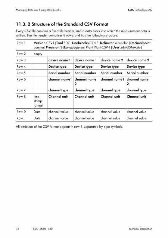
Managing Data and Saving Data Locally SMA Technologie AG
76 SDC-TEN081450 Technical Description
11.3. 2 Structure of the Standard CSV FormatEvery CSV file contains a fixed file header, and a data block into which the measurement data is written. The file header comprises 8 rows, and has the following structure:
All attributes of the CSV format appear in row 1, separated by pipe symbols.
Row 1 Version CSV1|Tool SDC|Linebreaks CR/LF|Delimiter semicolon|Decimalpoint comma|Precision 3|Language en|Plant Plant-CSV-1|User [email protected]|
Row 2 empty
Row 3 device name 1 device name 1 device name 2 device name 2
Row 4 Device type Device type Device type Device type
Row 5 Serial number Serial number Serial number Serial number
Row 6 channel name1 channel name2
channel name1 channel name2
Row 7 channel type channel type channel type channel type
Row 8 time stamp format
Channel unit Channel unit Channel unit Channel unit
Row 9 Date channel value channel value channel value channel value
Row... Date channel value channel value channel value channel value

Managing Data and Saving Data Locally SMA Technologie AG
Technical Description SDC-TEN081450 77
11. 4 Direct Data Acquisition from an InverterThis chapter describes how to acquire and save data from an inverter connected directly to the PC, and how to send these to Sunny Portal. With a direct connection of a PC to an inverter, the data can only be saved as CSV data (SUO format, SMA-Sunny Online).
11.4. 1 Set data storageThe settings for the data storage of an inverter which is directly connected to the PC are described below.
1. Choose "Continuous data recording/settings"
The "Settings" window opens.
2. Change the frequency with which data from the inverter should be queried in the field "Request cycle". At the "User" security level this is preset at 30 seconds. At the "Installer" security level this is preset at 15 seconds.
Note on SB4000TL-20/5000TL-20 and Sunny Portal.
If the data from SB 4000TL-20/5000TL-20 is queried via Bluetooth, it cannot be sent to Sunny Portal.
• To send the data to Sunny Portal, it must be queried via RS485 communication.

Managing Data and Saving Data Locally SMA Technologie AG
78 SDC-TEN081450 Technical Description
3. In the "Recording" area there are two options:
- "All values" = The channels are read at the query cycle intervals set and their values are recorded in these intervals.
- "Average values" = The channels are read at the query cycle intervals set, but their values are recorded at intervals set in the "Averaging over" drop-down menu. The average value is communicated and recorded only over the analog channels (e.g., Pac, Fac, Uac). In all other channels the values captured last are the ones recorded. This option can reduce the amount of data considerably, without losing their significance.
4. In the area "Autostart", the user can set the start and stop times during which Sunny Data Control should record all selected measurement channels.
Chapter 11.4. 2 describes how to start the data recording manually.
5. Click on <Settings>.
The window for setting the data storage opens.
6. In the field "Name" a name for the settings can be entered.
7. The data is stored in a user-specific directory by default:
C:\Documents and Settings\“Name of User“\Application Data\SMA\Sunny Data Control\Plants\“Plant name".If you wish to select a different directory, click on the folder icon.
8. Click on <Select columns...>.
The "Select columns" window opens.
9. In the "Description" drop-down menu, select the date format with which the date should be shown on the column.

Managing Data and Saving Data Locally SMA Technologie AG
Technical Description SDC-TEN081450 79
10. Click on <New>.
The column label "channel" is introduced.
You can insert a new column above a highlighted column with <Insert>.
With <Delete>, you can delete the highlighted column.
With <New>, you can add a new column beneath all the other columns.
11. Click on <...>.
The"Channel selection..." window opens.
If you are logged in as an installer, more channels are available to choose from.
12. You can add individual channels, or all of a node's channels together, via drag and drop or witht the arrows.
13. Click on <Apply>.
The "Select columns" window is displayed once more.
14. You can add additional columns in the same manner if you so wish.
15. Click on <Apply>.
The window for setting the data storage opens again.
16. Click on <Details>.
Only the line wrap for the operating system can be set in the data storage for an inverter directly connected to the PC.
The file name format is fixed to "YYMMDDNN.suo".
- {YYYY} = stands for year (if {YY} is selected, the last two digits of the year are displayed, e.g. "07“. If {YYYY} is selected, the year is shown in full, e.g. "2007“).
- {MM} = stands for month (01 to 12 are displayed)
- {DD} = stands for day (01 to 31 are displayed)
- {NN} = sequential number
17. Choose the line break format for the PC operating system.
18. Click on <Apply>.

Managing Data and Saving Data Locally SMA Technologie AG
80 SDC-TEN081450 Technical Description
11.4. 2 Saving and Viewing DataThis chapter describes how to acquire and save data from an inverter connected directly to the PC. The data can be saved only after you have set up the data storage as described in chapter 11.4. 1.
Begin Continuous Data Recording1. Choose "Continuous data recording/Start" or click on the "Record" icon.
On the lower edge of the screen you can see how long the data recording has been running.
During data recording all menu items are deactivated, with the exception of "Data", "Continuous data recording" and "Extras".
The "Record" icon becomes a "Stop" icon.
Stopping Continuous Data Recording.2. If you want the data recording to stop, click on the "Stop" symbol, or choose "Data Recording/
Stop".
Viewing Data3. Click on the "Show" icon.
The window for choosing the data opens.
4. Select the chosen data and click on "Open".
Excel starts.
5. Click on <Enable Macros>.
The data is listed on an Excel table.
You can read how to create a diagram based on the data in chapter 11. 8 "Creating a Chart in Excel" (Page 92).
11.4. 3 Sending Data to Sunny PortalHow to send data to Sunny Portal is described starting on chapter 12. 3 "Configuring Sunny Portal Mail" (Page 99).
Note on SB4000TL-20/5000TL-20 and Sunny Portal.
If the data from SB 4000TL-20/5000TL-20 is queried via Bluetooth, it cannot be sent to Sunny Portal.
• To send the data to Sunny Portal, it must be queried via RS485 communication.
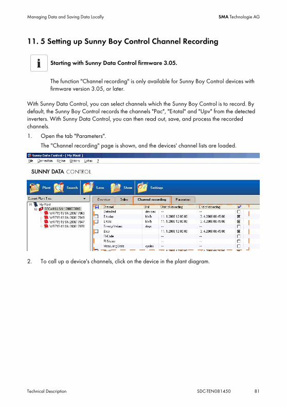
Managing Data and Saving Data Locally SMA Technologie AG
Technical Description SDC-TEN081450 81
11. 5 Setting up Sunny Boy Control Channel Recording
With Sunny Data Control, you can select channels which the Sunny Boy Control is to record. By default, the Sunny Boy Control records the channels "Pac", "E-total" and "Upv" from the detected inverters. With Sunny Data Control, you can then read out, save, and process the recorded channels.
1. Open the tab "Parameters".
The "Channel recording" page is shown, and the devices' channel lists are loaded.
2. To call up a device's channels, click on the device in the plant diagram.
Starting with Sunny Data Control firmware 3.05.
The function "Channel recording" is only available for Sunny Boy Control devices with firmware version 3.05, or later.

Managing Data and Saving Data Locally SMA Technologie AG
82 SDC-TEN081450 Technical Description
A list of the device's archive channels is displayed.
3. Click in the box next to the "End of recording" column for the respective channel (under the symbol seen in the figure to the right), thus adding or removing a cross. If a cross is added, the channel is recorded in the Sunny Boy Control.
The "commit" button appears.
4. Click on one of the <Commit> buttons to apply the new settings, and to transfer them to the Sunny Boy Control.
Calling up newly recorded channels.
The first channel values of a newly recorded channel are only accessible after the Sunny Boy Control's recording interval has passed. This is usually after 15 minutes.
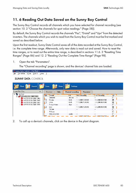
Managing Data and Saving Data Locally SMA Technologie AG
Technical Description SDC-TEN081450 83
11. 6 Reading Out Data Saved on the Sunny Boy ControlThe Sunny Boy Control records all channels which you have selected for channel recording (see section 10. 2 "Choose the channels for spot value readings." (Page 58)).
By default, the Sunny Boy Control records the channels "Pac", "E-total" and "Upv" from the detected inverters. The channels which you wish to read from the Sunny Boy Control must be first marked and saved as described below.
Upon the first readout, Sunny Data Control saves all of the data recorded at the Sunny Boy Control, i.e. the complete time range. Afterwards, only new data is read out and saved. How to reset the time ranges, or to read out the entire time range, is described in sections 11.6. 3 "Resetting Time Ranges" (Page 86) and 12. 2 "Reading Out the Complete Time Range" (Page 98).
1. Open the tab "Parameters".
The "Channel recording" page is shown, and the devices' channel lists are loaded.
2. To call up a device's channels, click on the device in the plant diagram.

Managing Data and Saving Data Locally SMA Technologie AG
84 SDC-TEN081450 Technical Description
A list of the device's archive channels is displayed.
3. In the "Channel query" column (under the icon seen in the figure to the right), in the field next to the channel, click to place or remove a check mark. If a check mark is added, the channel is marked to be saved.
4. Repeat this procedure for each device.
5. Click on the "Save" icon. The submenu opens.
6. If you wish to save all marked channels, click on "Download all marked archiv channels".
If you wish to save all energy channels, click on "Download all energy values".
Data transfer begins. This process can take several minutes, depending on the data volume.
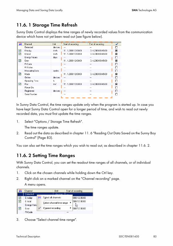
Managing Data and Saving Data Locally SMA Technologie AG
Technical Description SDC-TEN081450 85
11.6. 1 Storage Time RefreshSunny Data Control displays the time ranges of newly recorded values from the communication device which have not yet been read out (see figure below).
In Sunny Data Control, the time ranges update only when the program is started up. In case you have kept Sunny Data Control open for a longer period of time, and wish to read out newly recorded data, you must first update the time ranges.
1. Select "Options / Storage Time Refresh".
The time ranges update.
2. Read out the data as described in chapter 11. 6 "Reading Out Data Saved on the Sunny Boy Control" (Page 83).
You can also set the time ranges which you wish to read out, as described in chapter 11.6. 2.
11.6. 2 Setting Time RangesWith Sunny Data Control, you can set the readout time ranges of all channels, or of individual channels.
1. Click on the chosen channels while holding down the Ctrl key.
2. Right click on a marked channel on the "Channel recording" page.
A menu opens.
3. Choose "Select channel time range".

Managing Data and Saving Data Locally SMA Technologie AG
86 SDC-TEN081450 Technical Description
4. Select "All channels" or "Selected channels only".
The window for setting the time range opens.
5. Click on the end or the beginning of the time range and drag it while holding down the mouse button. The date of the new time range is displayed immediately.
6. Click on <Ok>.
11.6. 3 Resetting Time RangesThis function is necessary if you also wish to read out data from the Sunny Boy Control which have already been queried. Sunny Data Control keeps a record of the time ranges which have already been read out from the Sunny Boy Control, and normally only queries new data. You can reset the Sunny Data Control time ranges as follows:
1. Choose "Extras/Reset time ranges".A security question is shown.
2. Confirm the prompt with <Yes> in order to reset the time ranges.

Managing Data and Saving Data Locally SMA Technologie AG
Technical Description SDC-TEN081450 87
11.6. 4 Structure of the Excel Files
The data is saved as Excel files on your PC in the respective plant's directory. The directory has the name of the plant which you have created in Sunny Data Control.
By default, the plants' data is in the directory:
"C:\Dokumente und Einstellungen\<Benutzername>\Eigene Dateien\SMA\Sunny Data Control\Plants".
If you have already saved plant data with earlier versions of Sunny Data Control, your directory containing the plant data will continue to be used (C:\Programme\SMA\Sunny Data Control\Plants).
If you selected a different directory on your PC during installation of Sunny Data Control, open the directory in which Sunny Data Control is saved, and open the directory "Plants".
In the saved data, a distinction is made between measurement data and daily energy data. This data is read out from the Sunny Boy Control separately, and is saved in separate files.
• Daily files are saved together in a consolidated yearly file.
• All other measured values are saved together in consolidated monthly files.
For each Sunny Boy Control, there is a subdirectory with a name which comprises the text "SBC" and the device's serial number (e.g. SBC119010325).
This is where the files with the saved measurement data are situated. The measurement data from the individual channels is sorted according to day, and is saved on a monthly basis in the corresponding devices' subdirectories in separate Excel files.
Thus, the number of files is determined by the measurement period. For instance, if measurement data was recorded over an entire year with the Sunny Boy Control, there would be twelve files with monthly values on your hard drive after saving.
Beispiel Dateien von Sunny Boy Control.
The structure of the Excel files is explained on the basis of files which have been read out from a Sunny Boy Control. Files read out from a Sunny Beam have a similar structure.

Managing Data and Saving Data Locally SMA Technologie AG
88 SDC-TEN081450 Technical Description
Example of an Excel File
Monthly values
(SDM_YYMM.xls)
Year
Daily energy values
(SDT_YY.xls)
Year Month
Monthly values, if the measuring interval is lower than 3 minutes
(SDM_YYMMDD.xls)
Year Month Day
Channel access key
Measured values
Channel unitDevice name (Device type/Serial number).
Device ID
Device type
serial number)
Selection of pages using tabs.
Date and time of the measurement

Managing Data and Saving Data Locally SMA Technologie AG
Technical Description SDC-TEN081450 89
11. 7 Configuring the Automatic ReadoutThe automatic readout can only be performed if both the PC and Sunny Data Control are on.
With the automatic readout, data is automatically queried from the Sunny Boy Control at intervals of a length which you define, and is saved in Sunny Data Control. Only the devices displayed on the page "Spotvalues" are taken into account.
11.7. 1 Starting a New Task1. Choose "Options / Settings"
2. Select "Automatic Readout".
3. Check "Active"
4. Click on <+>.
Use with Sunny Beam is limited.
With the Sunny Beam, the function "Automatic Readout" only makes sense if the Sunny Beam is permanently connected to the PC with a USB cable.
Spot value querying is not updated.
During the automatic readout, the spot value querying does not update until the readout is complete. In the bar at the lower edge of the screen, you can see whether data is currently being read out (see figure).

Managing Data and Saving Data Locally SMA Technologie AG
90 SDC-TEN081450 Technical Description
The window shown below opens.
5. Adjust the settings as desired.
• Name
In the "Name" field (see figure below), type in the desired name for the automatic readout task (e.g. which plants the task involves).
• Auto Start
Here you can specify when the automatic query is to start.
Two possibilities are available.
- Once per day
Here, you can specify on which day of the week (or daily) and at what time of day the automatic readout is to start.
- Cyclically
Here you can specify between what times and at what intervals (after how many minutes) the automatic readout should begin.
6. In the "Plants" area select the plants to which these settings will apply.
(Click on the names of the plants in the "Available Plants" field, and add them to the "Assigned Plants" field with the arrow button ">").
7. Click on <Apply>.

Managing Data and Saving Data Locally SMA Technologie AG
Technical Description SDC-TEN081450 91
The "Settings" window opens again.
The name of the task which has been set and the start time are shown in the window.
8. Click on <Ok>.
11.7. 2 Editing / Deleting a Task1. Choose "Options / Settings"
The "Settings" window opens.
2. Select "Automatic Readout".
3. Click on the name of the task to be edited.
4. Edit the task:
• Click on < -- > to delete the task immediately.
• To edit the task, click on <Settings>.
The window for setting the task opens.
Adjust the settings as desired.
5. Click on <Ok>.
11.7. 3 Deactivating the Automatic Readout1. Choose "Options / Settings"
The "Settings" window opens.
2. Select "Automatic Readout".
3. Uncheck "Active".
4. Click on <Ok>.

Managing Data and Saving Data Locally SMA Technologie AG
92 SDC-TEN081450 Technical Description
11. 8 Creating a Chart in ExcelYour recorded measured values can easily be analyzed graphically with Excel. The data is also automatically visualized in a chart.
To this end, there are two options, which are described in the next sections.
• Automatic analysis:
The analysis is started via Sunny Data Control. Excel opens automatically with the data analysis macro.
• Manual analysis:
Manual analysis is only required if you wish to start the analysis on a PC on which Sunny Data Control is not installed. The analysis is then started directly from Excel, and the macro is executed manually.

Managing Data and Saving Data Locally SMA Technologie AG
Technical Description SDC-TEN081450 93
11.8. 1 Automatic AnalysisThe automatic analysis is started in Sunny Data Control. Excel opens automatically with the macro which has been specially written for the analysis.
1. Click on the "Show" icon.
The submenu opens.
2. Select "Excel files", or the CSV type which you have created for saving CSV files (see section 11. 3 "Saving Data in CSV Format" (Page 71)).
The window for choosing the data opens.
3. Select the desired plant. By default, the current plant is always displayed.
4. Open the directory of the chosen device.
5. Open the Excel file which contains the data that you wish to analyze.
Excel launches automatically, and a confirmation prompt opens.
The data analysis macro is situated in the file "Excel97\sdcmac.xls" in the Sunny Data Control directory on your PC. Only if you activate the macro, data analysis can be performed.
6. Add a check mark to the left of "Always trust macros from this source". This check mark causes the data analysis macro to be activated automatically every time Excel is opened via Sunny Data Control.
7. Click on <Enable Macros>.

Managing Data and Saving Data Locally SMA Technologie AG
94 SDC-TEN081450 Technical Description
8. If needed, click on the appropriate tab in Excel.
Creating the Chart9. In Excel, select "Sunny Boy / Chart" (see figure below).
The window "Create chart" opens.
10. Choose the channels which are to be shown from the list. Choose multiple channels by holding down the Ctrl key while selecting. The selected channels are highlighted in color.

Managing Data and Saving Data Locally SMA Technologie AG
Technical Description SDC-TEN081450 95
11. Make the desired settings for the chart display.
• Start and End
the start and end (dates and times) of the interval, from which data is to be displayed. Take care to choose a display interval which is not too large, as Excel can display a maximum of 4000 data sets in one chart.
• Increment
indicates the increment in rows, from which the measured values are to be taken. For example, with "10 rows", only every tenth row of the measured values is included.
12. Click on <Ok>. The chart is displayed.
11.8. 2 Manual AnalysisManual analysis is only required if you wish to start the analysis on a PC on which Sunny Data Control is not installed. How to start the analysis directly from Excel and manually execute the analysis macro is described below.
1. Launch the program "Excel".
2. Open the file "Excel97\sdcmac.xls“.
By default, the file is situated in the directory "Programs\SMA\Sunny Data Control\Excel97“.
The data analysis macro is situated within this file. To guard against unintentional alterations, this file is write-protected. If you wish to alter the macro, you must first remove the write-protection (password: SMA).
Excel launches automatically, and a confirmation prompt opens.
3. Add a check mark to the left of "Always trust macros from this source". This check mark causes the data analysis macro to be activated automatically every time Excel is opened via Sunny Data Control.
4. Click on <Enable Macros>.

Managing Data and Saving Data Locally SMA Technologie AG
96 SDC-TEN081450 Technical Description
Once the file has opened, the additional menu "Sunny Boy" is displayed in the table view (see figure below).
5. Open the chosen file.
By default, data from your plants saved in Excel format reside in the directory "Programs\SMA\Sunny Data Control\Plants“, and there in subdirectories for your respective plants.
By default, data from your plants saved in CSV format reside in the directory“C:\Documents and Settings\“Name of User“\Application Data\SMA\Sunny Data Control\Plants\“Plant name“\“Name of directory“.
6. Click on the tab for the chosen device.
Creating the Chart7. In Excel, select "Sunny Boy / Chart".
The window "Create chart" opens.

Managing Data and Saving Data Locally SMA Technologie AG
Technical Description SDC-TEN081450 97
8. Choose the channels which are to be shown from the list. Multiple selection is possible.
9. Make the desired settings for the chart display.
• Start and End
the start and end (dates and times) of the interval, from which data is to be displayed. Take care to choose a display interval which is not too large, as Excel can display a maximum of 4000 data sets in one chart.
• Increment
indicates the increment in rows, from which the measured values are to be taken. For example, with "10 rows", only every tenth row of the measured values is included.
10. Click on <Ok>. The chart is displayed.

Transferring Data to the Internet SMA Technologie AG
98 SDC-TEN081450 Technical Description
12 Transferring Data to the Internet
12. 1 System RequirementsUtilization of the Internet functionality requires the following to be in place:
• Any pre-installed web server with an MS Windows operating system (Windows 2000 or Windows XP recommended).
• A JAVA-1.1-capable Internet browser (e.g. Firefox version 1.0, or later, or MS Internet Explorer version 4.x) on the part of the Internet visitor, for presentation and display of Java applets.
• TCP/IP protocol installed on the same computer on which Sunny Data Control is installed.
12. 2 Reading Out the Complete Time RangeThis function is necessary if you have already read out data from your communication device with Sunny Data Control, and have not yet sent them to the portal. With this function, the next time querying is performed, you can query the complete time range from your communication device, and send it to Sunny Portal.
1. Choose "Options / Settings"
The "Settings" window opens.
2. Select "Misc“.
3. Add a check mark beside "Readout complete time range next download".
4. Click on <Ok>.
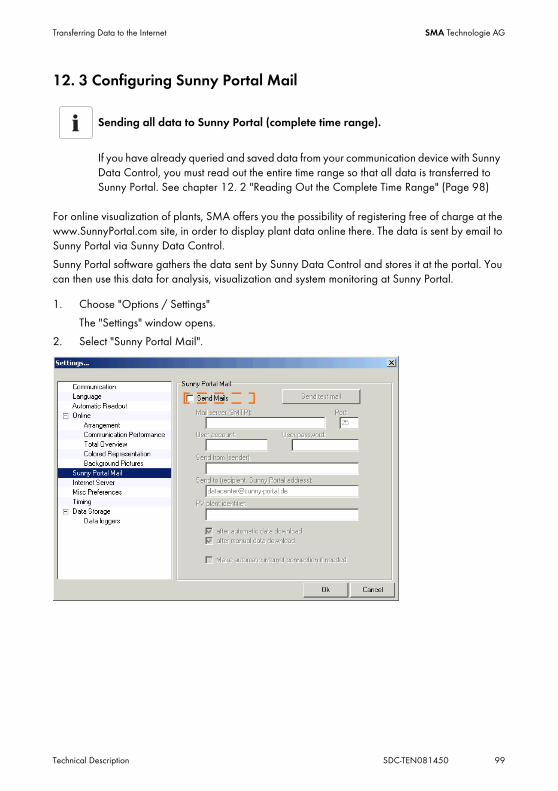
Transferring Data to the Internet SMA Technologie AG
Technical Description SDC-TEN081450 99
12. 3 Configuring Sunny Portal Mail
For online visualization of plants, SMA offers you the possibility of registering free of charge at the www.SunnyPortal.com site, in order to display plant data online there. The data is sent by email to Sunny Portal via Sunny Data Control.
Sunny Portal software gathers the data sent by Sunny Data Control and stores it at the portal. You can then use this data for analysis, visualization and system monitoring at Sunny Portal.
1. Choose "Options / Settings"
The "Settings" window opens.
2. Select "Sunny Portal Mail".
Sending all data to Sunny Portal (complete time range).
If you have already queried and saved data from your communication device with Sunny Data Control, you must read out the entire time range so that all data is transferred to Sunny Portal. See chapter 12. 2 "Reading Out the Complete Time Range" (Page 98)

Transferring Data to the Internet SMA Technologie AG
100 SDC-TEN081450 Technical Description
3. Add a check mark beside "Send Mails".
4. Make the following settings.
• Mail Server (SMTP)
Type in the IP address of your email provider (e.g. "smtp.t-online.de“ for T-Online, or that of your company's mail server).
• Port
Specify the port which corresponds to the IP address (SMTP=25).
• User identifier:
Type in the name under which you are registered at the mail server.
• User password
Type in the password for your email.
• Sender
Type in your email address.
• Recipient (Sunny Portal address)
The Sunny Portal email address is always "[email protected]".
• PV plant identifier
In the field "PV plant identifier", type in any name for your plant (e.g. SampleSystem).
If the plant identifier you choose is already used in Sunny Portal, you will receive an error message by email. You will then need to use a different name as your PV plant identifier.

Transferring Data to the Internet SMA Technologie AG
Technical Description SDC-TEN081450 101
5. Specify when the Sunny Portal email is to be sent.
• After automatic data download
For this option, automatic readout must be configured. See section 11. 7 "Configuring the Automatic Readout" (Page 89).
• After manual data download
The Sunny Portal email is sent whenever you read out the Sunny Boy Control's data storage. See section 11. 6 "Reading Out Data Saved on the Sunny Boy Control" (Page 83). Alternatively, the data is sent when you click on the menu item "Extras / Send Sunny Mail".
6. If the Internet connection is to be established automatically, add a check mark beside "Make automatic internet connection if needed".
Sending a Test Email7. You can test your settings by clicking on <Send test mail>.
If your settings are correct, Sunny Portal sends a test email to the email address which you have specified.
In the event that you have not yet registered at Sunny Portal under the specified email address, an email is automatically issued by Sunny Portal, advising you of the need to register at Sunny Portal to enable your plant data to be set up.
If you have already registered at Sunny Portal under the specified email address, the email indicates that you can send your plant data to Sunny Portal.
8. Click on <Ok>.

Transferring Data to the Internet SMA Technologie AG
102 SDC-TEN081450 Technical Description
12. 4 Sending Sunny Portal MailThe data is sent to Sunny Portal either after an automatic data query, or after a manual data query, depending on whether you have selected "automatic" or "manual" data querying via the menu item "Settings / Sunny Portal Mail". See section 12. 3 "Configuring Sunny Portal Mail" (Page 99).
12.4. 1 After Automatic Data QueryIf you have selected "after automatic data download", the data is automatically transferred from the Sunny Boy Control to Sunny Data Control after the set interval (see section 11. 7 "Configuring the Automatic Readout" (Page 89)), and subsequently sent to Sunny Portal.
12.4. 2 After Manual Data QueryIf you have selected "after manual data download", the data is sent to Sunny Portal as soon as you save the data from the Sunny Boy Control. See section 11. 6 "Reading Out Data Saved on the Sunny Boy Control" (Page 83).
Or when you choose „Extras/Send Sunny-Mail“.
12. 5 Transferring the Device Overview to the InternetWith Sunny Data Control, it is possible to transfer the complete spot values display, which appears on the "Device Overview" page, to the Internet. In so doing, the positions of the devices, the capacity utilization, the color values, etc., are recorded in an ASCII text file (online data file).
To enable this data to be transferred to the Internet, the writing of the online data file must first be activated, as described in the next section.
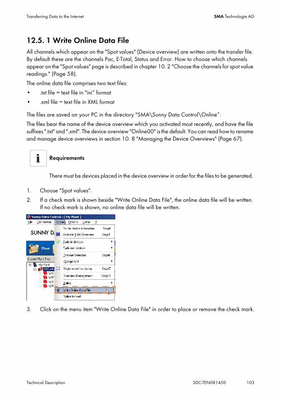
Transferring Data to the Internet SMA Technologie AG
Technical Description SDC-TEN081450 103
12.5. 1 Write Online Data FileAll channels which appear on the "Spot values" (Device overview) are written onto the transfer file. By default these are the channels Pac, E-Total, Status and Error. How to choose which channels appear on the "Spot values" page is described in chapter 10. 2 "Choose the channels for spot value readings." (Page 58).
The online data file comprises two text files:
• .txt file = text file in "ini“ format
• .xml file = text file in XML format
The files are saved on your PC in the directory "SMA\Sunny Data Control\Online“.
The files bear the name of the device overview which you activated most recently, and have the file suffixes ".txt" and ".xml". The device overview "Online00" is the default. You can read how to rename and manage device overviews in section 10. 8 "Managing the Device Overviews" (Page 67).
1. Choose "Spot values".
2. If a check mark is shown beside "Write Online Data File", the online data file will be written. If no check mark is shown, no online data file will be written.
3. Click on the menu item "Write Online Data File" in order to place or remove the check mark.
Requirements
There must be devices placed in the device overview in order for the files to be generated.

Transferring Data to the Internet SMA Technologie AG
104 SDC-TEN081450 Technical Description
12.5. 2 Structure of the Online Data FilesThe structure of the online data files is explained below.
Online Data File in Text Format (".txt")In the online data file, certain characters have a special meaning:
• ";" (semicolon) serves as a separator between the individual values
• "#" (hash) marks the start of a comment (for the entire row)
The file begins with a comment. This is followed by the date and time of the file's last update. These are separated from each other by a semicolon:
#This file is created automatically!
<Date> / <time>
Each additional row represents exactly one device, with all of its properties, in the spot values display. In turn, the respective values are separated from each other by semicolons.
For improved legibility, the entries are shown below arranged in rows, one beneath the other.
<device position X:Y>
<channel name for capacity>;<present capacity as a percentage>;<number of colors in palette>;
<channel 1 name>;<channel 1 value>;<channel 1 unit>;
<channel 2 name>;<channel 2 value>;<channel 2 unit>;
...
<channel n name>;<channel n value>;<channel n unit>
The example file was updated on 2006-06-18 at 15:30:32. The plant comprises a total of 2 devices:
Device 1:
Position (0:0), channel "Pac" as capacity utilization channel, 95.1 % present capacity utilization, color palette used contains 90 colors. This is followed by the device's displayed channel "E-Total", with the value 50529 and unit "kWh".
Example
Line 1: #This file is created automatically! Rev. 1.00
Line 2: 18.06.2006;15:30:32
Line 3: 0:0;Pac;95.1;90;E-Total;50529;kWh;
Line 4: 1:1;Pac;94.6;90;Upv_Ist;771;V;Upv_Soll;771;V;Iac_Ist;771;mA;Uac;771;V;Fac;7.71;Hz;Pac;771;W;Riso;771;kOhm;Ipv;771;mA;E_Total;842;kWh;h_Total;14035;h;
Transferring Data to the Internet SMA Technologie AG
Technical Description SDC-TEN081450 105
Device 2:
Position (1:1), channel "Pac" as capacity utilization channel, 94.6 % present capacity utilization, 90 colors displayed. All listed channels follow: channel "Upv-Ist" with value 771 and unit "V". The last channel is "h-Total" with the value 14035 and the unit "h".
Online Data File in XML Format (".XML")The same measured values are saved in this file, as in the plain text file described above. The only difference is the format used. Here, the data is saved in XML format.
XML (Extensible Markup Language) is a data definition language, standardized by the consortium W3C. This enables, among other things, simple exchange of data over the Internet. For this reason, the online displays' measured values are also saved in this format. You can acquire more detailed information regarding XML online at "www.w3c.org".
The file begins with the normal XML header, followed by a brief comment:
?xml version="1.0" encoding="ISO-8859-1" ?
<!--
**** Sunny Data Control Online Display Data File ****
…
-->
Directly afterwards, the "root element" of the document <OnlineData> begins:
<OnlineData>
<Date>2002-10-02</Date>
<Time>15:01:31</Time>
…
</OnlineData>
Within the root element are the elements "<date>" and "<time>", which indicate the date and time when the file was created.
This is followed by the "<devices>" element, in which all devices in Sunny Data Control's online display are now saved. Each device is described by a "<device>" element entry:
devices
<device>
...
</device>
<device>
...
</device>
…
devices

Transferring Data to the Internet SMA Technologie AG
106 SDC-TEN081450 Technical Description
Within such a "<device>" element, information regarding the device (Sunny Boy or Sunny Boy Control) is recorded:
<Device>
<Name>SBC+9tgf SN:114413059</Name>
<SerNr>114413059</SerNr>
<PositionX>0</PositionX>
<PositionY>0</PositionY>
<PerformChanName>Pac</PerformChanName>
<Perform>72</Perform>
<ColorCount>90</ColorCount>
<Channels>
. . .
<Channels>
</Device>
From this, the following settings are to be derived:
Device name = "SBC+9tgf SN:114413059"
Serial number = "114413059"
Device position in the online display (x,y) = 0/0 ("top left")
Capacity utilization channel: "Pac"
Present capacity utilization: 72 percent
Number of colors in palette: 90 colors
In the element "<Channels>", all of the device's channels which are also included in the online display are now listed. Each channel is recorded in a "<Channel>" entry:
<Channels>
<Channel>
<Name>Pac</Name>
<Value>1234.000</Value>
<Unit>kW</Unit>
</Channel>
. . .
<Channels>
From this, in turn, the following information can be derived:
Channel name = "Pac"
Channel value = "1234.000"
Channel unit = "kW"

Transferring Data to the Internet SMA Technologie AG
Technical Description SDC-TEN081450 107
The number of occurrences of the "<Channel>" element within the "<Channels>" element is equal to the number of channels included in the online display for this device.
Below is a cohesive section of an example file:
?xml version="1.0" encoding="ISO-8859-1" ?
<!--
**** Sunny Data Control Online Display Data File ****
-->
<OnlineData>
<Date>2002-10-14</Date>
<Time>17:03:27</Time>
<Devices>
<Device>
<Name>SBC+9tgf SN:114413059</Name>
<SerNr>114413059</SerNr>
<PositionX>0</PositionX>
<PositionY>0</PositionY>
<PerformChanName>Pac</PerformChanName>
<Perform>72</Perform>
<ColorCount>90</ColorCount>
<Channels>
<Channel>
<Name>Pac</Name>
<Value>1234.000</Value>
<Unit>kW</Unit>
</Channel>
<Channel>
<Name>E-Total</Name>
<Value>2345</Value>
<Unit>kWh</Unit>
</Channel>
<Channels>
</Device>
. . .
</Devices>
</OnlineData>

Transferring Data to the Internet SMA Technologie AG
108 SDC-TEN081450 Technical Description
12. 6 Internet Server (SDC Agent)
12.6. 1 OverviewSunny Data Control's Internet server function enables you to display any of a PV plant's measured values directly online in an interactive HTML page. In this context, the application operates as a server. For the display of measured values in an HTML page, Java applets are used in a client / server environment.
Fundamental Communication Structure
When the HTML page is accessed, the Java applet is downloaded from the web server and launched in the browser. It independently establishes a connection to the server.
HTML knowledge is needed.
Setting up a web page with your plant's present operating data requires some knowledge of HTML, IP addresses, and Java applets. If you do not feel absolutely confident in this field, consult a specialist.
Java applet
Web client
Internet
Location
SDC agent
Web server computer
HTMLAppletPC with Sunny Data Control
SBC
Web server
SMA
-Net
TCP/IP
TCP/IP

Transferring Data to the Internet SMA Technologie AG
Technical Description SDC-TEN081450 109
The tool "SDC agent" serves as a communication intermediary between the Java applets and Sunny Data Control. For this purpose, it is installed on the HTML web server's computer. The communication between the applets and the agent, as well as between Sunny Data Control and the agent, occurs via a dedicated TCP connection.
Two different modes of connection from the PV plant to Sunny Data Control serve as the information source for the applets' display of measured values.
Direct ConnectionThe Sunny Boy Control is permanently in contact with Sunny Data Control via a direct RS232 / RS485 connection. The measured values are queried directly from the connected PV plant, and transferred to the Internet.
This mode enables the entire range of all different display types to be shown on the applets. This mode is preferable, as it offers the most possibilities.
Offline ConnectionWith this mode, there is no permanent connection between the Sunny Boy Control and Sunny Data Control (e.g. only a temporary modem connection). The only data source is the content of the online data file (see section 12.5. 1 "Write Online Data File" (Page 103)).
This only enables the applets to show the device field display. No other display types are possible.

Transferring Data to the Internet SMA Technologie AG
110 SDC-TEN081450 Technical Description
12.6. 2 Configuring and Activating the Internet Server
Creating a New Internet Channel1. Choose "Options / Settings"
The "Settings" window opens.
2. Select "Internet Server“.
3. Click on <New>.
The name "Channel0" is added to the "Internet channels" list.
Click once on the name "Channel0". A frame appears around the name, and it can now be written over.
4. Type in the desired name for the new Internet channel (e.g. "Status").
Selecting Device Channels5. Click on <Channel select>.
Before making changes on an already save online channel first deactivate it.
If you wish to alter or delete an Internet channel which has already been configured, you must first remove the check mark beside "Server is active", so that the server is deactivated.

Transferring Data to the Internet SMA Technologie AG
Technical Description SDC-TEN081450 111
The "Channel select" window for the current plant opens.
6. Choose the desired channels from the "Channels available" list and move them to the "Selected Channels list using the arrows or "drag and drop".
You can only choose channels which use the same units of measurement.
7. Click on <Apply>.
The "Settings" window is displayed once more.
Multiple selection only with channels using the same units.
Multiple selection is only possible if the individual channels have the same unit of measurement (e.g. two "watts" channels [W]). The Internet channel is then made from the sum of these channels. Existing connections to the Java applets are then automatically disconnected from the server for technical reasons.

Transferring Data to the Internet SMA Technologie AG
112 SDC-TEN081450 Technical Description
Configuring the Server Port and Channel Scan
The server port setting specifies the TCP port at which the server awaits queries from the SDC agent. By default, this is set to port 18503.
The channel scan setting is the time waited (in seconds) between sending two channel updates.
8. If necessary, make the appropriate adjustments to the server port and channel scan settings.
9. Deallocate the router as described in its manual or contact the network administrator.
Offline ServerThe setting "Offline Server" makes it possible to choose between direct connection and offline connection of the PV plant. See section 12.6. 1 "Overview" (Page 108).
10. Add or remove the check mark beside "Offline Server", according to whether or not your Sunny Boy Control is directly connected to Sunny Data Control.
Server is Active11. Activate the server = check "Server is active".
Dectivate the server = uncheck "Server is active".
You can only make changes and adjust settings for the respective Internet channel if the check mark beside "Server is active" is first removed.
12. Click on <Ok>.
Consult the network administrator.
Only alter the server port and channel scan settings if you fully understand the consequences of the changes. Incorrect settings can result in the SDC agent no longer functioning.
If your Ethernet network is managed by a network administrator, contact this administrator so that the appropriate port on the router can be enabled.

Transferring Data to the Internet SMA Technologie AG
Technical Description SDC-TEN081450 113
12. 7 SDC agentThe SDC agent serves as a communication intermediary between the Java applets and Sunny Data Control on the web server. The SDC agent can manage a maximum of three server connections; thus, three PV plants can be communicated with simultaneously via one web server.
Prerequisites for Use• The "SDC agent" must be installed
(see Windows Start menu under "Programs/Sunny Data Control/SDCAgent").
• JavaScript must be activated in your browser (e.g. Internet Explorer).
Configuring the SDC AgentConfiguration can be made via any web browser.
We recommend that you include the SDC agent in the Windows autostart group, so that it is automatically launched every time the computer starts up. However, it can also be manually called up from the Windows Start menu (Programs/Sunny Data Control/SDCAgent/SDCAgent.exe).
1. Start the SDC agent.
(see Windows Start menu under "Programs/Sunny Data Control/SDCAgent").
The agent does not have its own graphical interface. With the Windows version, only a small window opens (see figure to the right), which after a brief moment automatically resides in the background. Do not close the window.
2. Open your web browser and type in the following URL:
http://<IP Adress>:18501, for <IP Adress> type in the IP Adress or the DNS Name of the computer on which the SDC Agent is installed.

Transferring Data to the Internet SMA Technologie AG
114 SDC-TEN081450 Technical Description
The main page for configuration of the SDC agent opens.
The agent's most important settings are to be found in the "Server" table (see figure above). Each server connection to Sunny Data Control occupies one row in the table.
Server Name (Alias)3. In the field "Server Name (Alias)", type in the desired name for the server.
The Java applets identify and communicate with each server on the basis of this name. Server names are case-sensitive.
IP Address (or DNS Name)4. In the field "IP Address (or DNS Name)", type in the IP address of the computer on which the
server software (Sunny Data Control) is installed.
Port5. In the "Port" field, only make changes if you have changed the default port. The number must
match the port number setting in Sunny Data Control. See section 12.6. 2 "Configuring and Activating the Internet Server" (Page 110). The default port setting is 18503.
6. Add a check mark in the "Activated" field in each respective row in order to allow the connections to Sunny Data Control.

Transferring Data to the Internet SMA Technologie AG
Technical Description SDC-TEN081450 115
SDC Agent Port7. This is where the client-side settings are made. The SDC agent port represents the TCP port via
which the Java applets can reach the SDC agent. The default port setting is 18500.
Max. Internet Clients8. The number of Java applets which the SDC agent can reach is stipulated here. The value
should be adapted to the available processor speed. The default setting is 50 clients.
Logging9. If you wish to record all access and/or errors, place a check mark on the appropriate fields.
10. Click on <Apply changes> to save the settings.
A message is briefly displayed, indicating that the new parameters have been set (see figure to the right). The main page for configuration of the SDC agent is then displayed again automatically. You can now close the browser. The settings have been applied.

Transferring Data to the Internet SMA Technologie AG
116 SDC-TEN081450 Technical Description
12. 8 The Java AppletThe Java applet is responsible for the actual graphic presentation of the PV plant on the web pages. Applets run on the web clients in the Internet, i.e. on the Internet surfers' computers.
An HTML page can contain one or more applets, as desired. However, the number per page should be kept as low as possible, as each applet establishes its own TCP connection to the web server, or to the SDC agent.
There are several different display types for the PV plants' measured values. In order to keep the number of required TCP connections as low as possible, one applet can show several display types simultaneously.
The configuration of applets occurs by means of applet parameters which are transferred to the applet in the HTML code of the respective page.
IntegrationIntegration of the applet into the HTML document takes place by means of the APPLET tag. At the desired location in the HTML page, the applet is introduced by the code word "<APPLET>“, and closed with "</APPLET>“.
<APPLET
ARCHIVE = "SunnyViewer.jar“
CODEBASE = ".“
CODE = "de.sma.SunnyViewer.SunnyApplet.class“
WIDTH = 900
HEIGHT = 400>
<PARAM name="1stParameterName" value=“1stParameterValue“>
. . .
</APPLET>
The parameter "ARCHIVE" describes the file (Java archive) which contains the applet. Here, please type "SunnyViewer.jar". "CODEBASE“ stipulates the directory in which the Java archive resides. A "." (period) indicates that the archive is situated in the same directory as the HTML page.
The amount of space which the applet occupies on the page is specified by "WIDTH" and "HEIGHT" (given in pixels). The actual applet for execution is specified by the "CODE" parameter, and should always be "de.sma.SunnyViewer.SunnyApplet.class“ (case-sensitive!).
In the sequence between "<APPLET>“ and "</APPLET>“, a series of PARAM tags are passed to the applet as parameters. These parameters are used for the actual configuration of the applet. The commands have the following syntax:
<PARAM name=“ParameterName“ value=“ParameterValue“>
...
The quotation marks are only necessary if the parameter value contains empty spaces. Four different parameter types are used:

Transferring Data to the Internet SMA Technologie AG
Technical Description SDC-TEN081450 117
• Bool: The value is either "0" (deactivated) or "1" (activated).
• Integer: A whole number.
• String: A series of characters (possibly in quotation marks).
• Color: Color value. The format is "#RRGGBB". This represents a 24-bit value. "RR" is the proportion of red, "GG" the green, and "BB" the proportion of blue. The color values are given in hexadecimal notation. This allows any hues within the displayable color spectrum to be defined.
The actual parameters are subdivided into the following categories:
• General applet parameters (settings common to all components)
• Parameters specific to the individual component types
12.8. 1 General Applet ParametersThe general applet parameters define the fundamental operating principles of the applet, and the settings which apply to all components.
BGColorThis parameter defines the background color of the area in the applet which is not covered by any display components. The parameter type is "color". The default value is white.
Color values
#ff0000 (red)
#00ff00 (green)
#0000ff (blue)
#0a0a5c (dark blue)
#ffffff (white)
Example: Background color
<PARAM name=BGColor value=#00003c>
This example sets the applet's background color to a dark blue.

Transferring Data to the Internet SMA Technologie AG
118 SDC-TEN081450 Technical Description
ChannelX, ChannelX.Name, ChannelX.Unit, ChannelX.SText (String)With these parameters, all Internet channels which are to be displayed in the applet within a component are defined. The "X" indicates the number of the channel, and must be replaced accordingly. The sequence begins with "1" and ends at a maximum of "10".
The ChannelX parameter describes the name of the Internet channel as defined in Sunny Data Control (see section 12.6. 2 "Configuring and Activating the Internet Server" (Page 110)). As the channel name is thus named in the display within the applet, you have the possibility of adapting the output text in the applet to another language, with the parameter ChannelX.Name. The same applies to the channel unit, which is defined by the parameter ChannelX.Unit. Unit and Name are optional.
With the parameter ChannelX.SText, you can assign a text to a channel's numerical value. The texts are specified within the parameter, separated by commas. The first text corresponds to the value "0". This parameter should only be used for status channels.
Status Channel SBC: Stop, wait, in operation, disruption, error, measuring
Status Channel SWR: Offset, Stop, Netzueb., Warten, U-Konst, I-Konst, Mpp-Such, Mpp, Stoer., Fehler
DisplayErrMsg (Bool)If the applet cannot establish a connection to the server, an automatic error message is generated. With this parameter, the messages can be suppressed. By default, the parameter has the value "1", which means that the messages are displayed.
If set to "0", all such error messages are suppressed.
Example
<PARAM name=Channel1 value=Betriebszeit>
<PARAM name=Channel1.Unit value=Stunden>
<PARAM name=Channel2 value=Leistung>
<PARAM name=Channel2.Name value=Performance>
<PARAM name=Channel3 value=Status>
<PARAM name=Channel3.Stext value= "Stop,Warten,Betrieb,Stoerung,Fehler,Erfassung“>
The example defines three channels. The first channel is "Betriebszeit", the channel unit of which is displayed in the applet as "Stunden". Channel 2, "Leistung", appears in the applet as "Performance". Channel 3 , "Status", assigns its values to texts as follows: 0 = "Stop“, 1 = "Warten“, 2 = "Betrieb“, etc.
Example
<PARAM name=DisplayErrMsg value=0>

Transferring Data to the Internet SMA Technologie AG
Technical Description SDC-TEN081450 119
Language (String)This setting can be used to set the language used by the applet. However, at present this setting only affects the "device field display". Here, the output of channel names and channel values is then given in the respective language.
The values "de" for German, and "en" for English can be selected. At present, Spanish texts are not supported here.
LayoutHSpace, LayoutVSpace (Integer)By default, a gap of 4 pixels is maintained between the components included in the applet. This can be separately adjusted horizontally and vertically with the parameters "LayoutHSpace" and "LayoutVSpace" respectively.
ServerAlias (String)This setting specifies the name of the (Sunny Data Control) server, measured values from which are to be displayed on the applet. The name is allocated in the SDC agent, and unambiguously identifies the desired server. This value is not optional, and must always be specified!
Example: Change language.
<PARAM name=Language value=“en“>
Sets the language of the applet ("device field components") to English.
Example
<PARAM name=LayoutHSpace value=0>
<PARAM name=LayoutVSpace value=0>
These settings switch the horizontal and vertical space between the components to 0 pixels (off).
Example
<PARAM name=ServerAlias value=ServerKassel>

Transferring Data to the Internet SMA Technologie AG
120 SDC-TEN081450 Technical Description
ServerPort (Integer)This parameter specifies the TCP port which aids the applet in establishing a TCP connection to the SDC agent (on the web server). The value must correspond to the SDC agent's settings. See section 12. 7 "SDC agent" (Page 113).
The default value is port 18500 if the parameter is not declared.
12.8. 2 Component-specific ParametersIn order to support different display types within an applet, each display type is accommodated in a separate Java component. The number of components, and thus the number of displays per applet, is limited to a maximum of four.
The Java applet has three different display types:
• Chart Display
With this display type, the values of an Internet channel are applied point by point to a coordinate system, which is defined by an X axis and a Y axis. A maximum of four channels can be shown simultaneously in this display. According to preference, display as a line chart or as an area chart can be selected. The line chart display connects the individual measured values' points to form a line. The area mode also fills in the area beneath the line.
• Device Field Display
As closely as possible, this display resembles the online display as already shown locally in Sunny Data Control (see section 2 Spot Values).
• Numerical Display
Here, the measured values are displayed as numerical values. Each row in this display represents exactly one measuring channel. The number of channels is only limited by the applet's height.
Example
<PARAM name=ServerPort value=12345>
This setting sets the communication port to 12345.
To be observed when using a firewall.
If you use a firewall, it is imperative to enable the specified TCP port between the Java applet and the agent on the web server!

Transferring Data to the Internet SMA Technologie AG
Technical Description SDC-TEN081450 121
ComponentX, NameX (String)Each component to be displayed is introduced with:
<PARAM name=ComponentX value=ChartType>
<PARAM name=NameX value=ChartName>
among the parameters. The parameter ComponentX specifies the component type (see above). Each display type has an unambiguous character string which identifies the type. In this case, "X" stands for the sequential component number. A maximum of four are possible, beginning with 1.
At present, the following values are possible for ComponentX:
• "de.sma.SunnyViewer.ViewerDiagram" (for chart display)
• "de.sma.SunnyViewer.ViewerDigital" (for numerical display)
• "de.sma.SunnyViewer.ViewerGrid" (for device field display)
With the parameter "NameX", an unambiguous name is assigned to the component. In subsequent procedures, the component is identified by this name. This is similar to the definition of a variable in a programming language.
There is a set of parameters supported by all components. Each parameter is preceded by the name of the component to which it applies, separated by a period.
BGColor (Color)This parameter defines the background color of this component.
Example
<PARAM name=Component1 value=de.sma.SunnyViewer.ViewerDiagram>
<PARAM name=Name1 value=chart1>
This example specifies that the first display component is a chart component, and that this can subsequently be referred to as "chart1".
Example
<PARAM name=chart1.BGColor value=#ffffff>
This example sets the background color of the component "chart1" to white.
Transferring Data to the Internet SMA Technologie AG
122 SDC-TEN081450 Technical Description
BGPicture (String)The parameter BGPicture defines the component's optional background image. The possible image formats are "JPEG" and "GIF". If this parameter is declared, it causes the BGColor parameter to become ineffective.
Draw3DFrame (Bool)By default, every component is surrounded by a 3D frame. With this parameter, the frame can be deactivated. With a value of "0", the frame is no longer displayed around the component.
FontName (String)The font to be used in the component is set with the aid of this parameter. The possible font names depend on the Internet browsers used (Java machines). Some of the possible font names are:
"Helvetica“, "TimesRoman“, "Courier“, "Dialog“
Please note that the font names are case-sensitive.
FontSize (Integer)This parameter defines the size of the font used. The default setting is "12".
Example
<PARAM name=chart1.BGPicture value=BackGround1.jpg>
This example causes the component "chart1" to display the image "BackGround1.jpg" in the background. The image size is automatically adapted to the size of the component.
Example
<PARAM name=chart1.Draw3DFrame value=0>
This example deactivates the 3D frame of the component "chart1".

Transferring Data to the Internet SMA Technologie AG
Technical Description SDC-TEN081450 123
Width, Height (Integer)Each component in the applet has its own height (Y) and width (X). The components are arranged in rows from left to right, on the basis of these two dimensions. If there is no longer sufficient space on the right in the applet, the component is positioned in the next row:
Width describes the horizontal dimensions and height describes the vertical dimensions of a component in the applet. The value is given in pixels.
Example
<PARAM name=chart1.Width value=100>
<PARAM name=chart1.Height value=50>
This example defines the size of the component "chart1" as 100 x 50 pixels.
Applet
Applet
Component 1 Component 2
Component 3 Component 4
Component 1 Component 2 Component 3
Component 4

Transferring Data to the Internet SMA Technologie AG
124 SDC-TEN081450 Technical Description
12.8. 3 Chart DisplayWith the aid of this component, channel values are displayed as a chart. Here, the values of the channel are applied to a Cartesian coordinate system as points, and interconnected by a line. As an option, the area beneath the line can be filled in.
Any text can be displayed as the title, centered within the display. This is also optional.
The display's legend serves to label the individual channel curves. This indicates the name, the unit in brackets, and the color of each respective channel.
The labeling of the X and Y axes is generated automatically. The maximum value for the Y axis is based on the largest value of one of the displayed channels, and is always displayed with one decimal place. The X axis represents time.
In order to show "chart display" components, the type "de.sma.SunnyViewer.ViewerDiagram“ must be entered in parameter "Component1".
The other parameters of this component type are listed below.
AxisColor (Color)Defines the color of the actual X and Y axes. By default, this optional parameter is set to black.
Example
<PARAM name=Component1 value=de.sma.SunnyViewer.ViewerDiagram>
Example
<PARAM name=chart1.AxisColor value=#ffffff>
Sets the color of the axes to white.

Transferring Data to the Internet SMA Technologie AG
Technical Description SDC-TEN081450 125
AxisLabelColor (Color)This parameter defines the color of both axes' labels. The default setting is #ffffff (white). This parameter is optional.
Channels (String)This parameter specifies which channels are to be displayed in this component. The channel names are listed, and separated by commas. Each name must be identical to that specified by the general parameter ChannelX.
Example
<PARAM name=chart1.AxisLabelColor value=#000000>
Sets the color of the axes' labels to black.
Example
<PARAM name=chart1.Channels value= "Betriebszeit,Leistung“>
This example specifies that in the component "chart1", the channels "Betriebszeit" and "Leistung" are to be displayed.

Transferring Data to the Internet SMA Technologie AG
126 SDC-TEN081450 Technical Description
ChartColorX (Color)This parameter defines the color of channel X. For "X", a channel number is entered, which corresponds to the channels' sequential order as defined by the "Channels" parameter. The possible numbers for "X" are 1 to 4. If this parameter is not declared, the following allocations occur:
1st channel => red
2nd channel => black
3rd channel => blue
4th channel => green
ChartStyle (String)This parameter defines the component's style. It is possible to specify whether the area beneath the line is to be filled in ("Fill"), or whether just the line itself ("Line") is to be displayed in the chart. This parameter is case-sensitive. This parameter is optional. If this parameter is not declared, just the line is displayed in the charts.
LegendBGColor (Color)This parameter is used to set the background color of the entire legend. If this parameter is not declared, the legend is displayed as transparent.
LegendTextColor (Color)This parameter defines the text color used to display the channel text and units in the legend. This parameter is optional. The default setting is #ffffff (white).
Example
<PARAM name=chart1.ChartColor1 value=#00ff00>
<PARAM name=chart1.ChartColor2 value=#0000ff>
<PARAM name=chart1.ChartColor3 value=#000000>
<PARAM name=chart1.ChartColor4 value=#ff0000>
This example sets the colors of the individual channels as follows:
1th channel => green
2rd channel => blue
3nd channel => black
4st channel => red
Example
<PARAM name=chart1.ChartStyle value= „Fill“>

Transferring Data to the Internet SMA Technologie AG
Technical Description SDC-TEN081450 127
LegendVis (Bool)This parameter specifies whether the chart's legend is to be displayed. The default setting for this optional parameter is "1" (is displayed). If set to "0", the legend will no longer be displayed.
MaxValue (Integer)With this parameter, an initial value can be set as the largest value to be displayed on the Y axis. If this parameter is not declared, the value is calculated according to the following formula:
MaxValue = [largest previous value of a channel] / 2 * 3
If a channel's maximum value is exceeded during display, the scale of the Y axis is dynamically adapted to the maximum value.
Title (String)This parameter defines the text which is to be displayed as a title above the chart. If this parameter is not declared, no title is displayed.
TitleColor (Color)The parameter TitleColor defines the color in which the title is displayed. This parameter is of type "color". The default value is white (#ffffff).
Example
<PARAM name=chart1.LegendVis value=0>
This deactivates the legend in component "chart1":
Example
<PARAM name=chart1.MaxValue value=3000>
This example sets the scale of the maximum value on the Y axis to 3000 (e.g. for output in W).
Example
<PARAM name=chart1.Title value=“Meine PV-Anlage“>

Transferring Data to the Internet SMA Technologie AG
128 SDC-TEN081450 Technical Description
ValLineColor (Color)This setting defines the color of the axis partitioning in the chart. The partitioning is drawn horizontally over the chart for each of the chart's scales (Y axis). By default, this optional parameter is set to the color #595959 (gray).
12.8. 4 Device Field DisplayThe component "ViewerGrid" implements Sunny Data Control's online display in the Java applet. With this component, individual devices are displayed in color in a chessboard-like field. In each of these fields, the device's measuring channels are also displayed.
The corresponding component type is "de.sma.SunnyViewer.ViewerGrid“.
The arrangement of the individual device fields, the channel text settings, and the color settings, are linked to Sunny Data Control's online display.
The applet also provides an enlargement function, which increases (left mouse button) or decreases (right mouse button) the size of a device field. With this function, it is possible to achieve a better view of the channel texts in each device field as, depending on the available space, it might not be possible to display them in full.
Example
<PARAM name=chart1.ValLineColor value=#000000>
This example sets the color of the axis partitioning in chart "chart1" to black.
Example
<PARAM name=Component2 value=de.sma.SunnyViewer.ViewerGrid>
<PARAM name=Name2 value=chart2>

Transferring Data to the Internet SMA Technologie AG
Technical Description SDC-TEN081450 129
The general applet parameter "Language" specifies the language of the measuring channels displayed in the component.
Apart from the general applet parameters (see section 12.8. 1 "General Applet Parameters" (Page 117)), this component does not support any other properties.
12.8. 5 Numerical DisplayWith the "ViewerDigital" component, it is possible to display a channel's present value numerically.
Each row represents a channel. The channel name is shown in the first column. Column 2 displays the most recent value from the channel as a numerical value, or as a channel text, depending on the channel shown. Column 3 displays the channel's unit. If status channels are used, a text can be allocated to each of a channel's values. The text is then displayed instead of the numerical value.
In principle, the number of displayable channels is unlimited. This number depends only on the graphical dimensions of the components, and on the font used.
The following example incorporates such a component:
As well as the general parameters described previously, this component has additional parameters, which are described below.
BGColor (Color)This parameter defines the background color of this component. If a background image is defined (parameter BGPicture), this parameter is ignored.
Example
<PARAM name=Component3 value=de.sma.SunnyViewer.ViewerDigital>
<PARAM name=Name3 value=chart3>
Example
<PARAM name=chart3.BGColor value=#ffffff>
This example sets the background color of the component "chart3" to white.
Transferring Data to the Internet SMA Technologie AG
130 SDC-TEN081450 Technical Description
Channels (String)This parameter specifies which channels are to be displayed in this component. The channel names are listed, and separated by commas. Each name must be identical to that specified by the general parameter "ChannelX" (see section 6.5.2).
ChanTextColor (Color)This parameter defines the text color with which the individual channel texts are shown in the component. The default value is "#ffffff" (white).
Title (String)This parameter defines the text which is to be displayed as a title above the chart. If this parameter is not declared, no title is displayed.
TitleColor (Color)The color of the title is defined with this optional parameter. The default setting is "#ffffff" (white).
ValueColor (Color)This parameter defines the text color with which the channel's values are displayed. The default setting is "#ffff00" (yellow).
Example
<PARAM name=chart1.Channels value= „Betriebszeit,Leistung,Status“>
Example
<PARAM name=chart3.Title value= „Aktuelle Werte“>
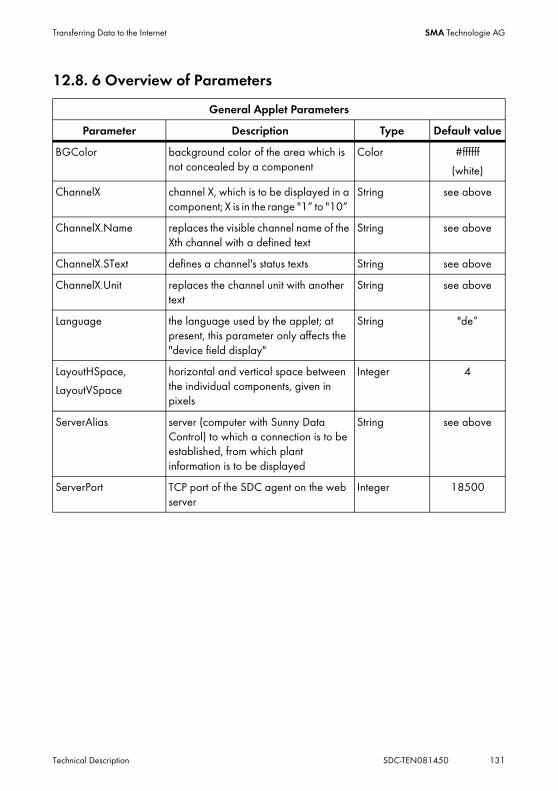
Transferring Data to the Internet SMA Technologie AG
Technical Description SDC-TEN081450 131
12.8. 6 Overview of Parameters
General Applet Parameters
Parameter Description Type Default value
BGColor background color of the area which is not concealed by a component
Color #ffffff
(white)
ChannelX channel X, which is to be displayed in a component; X is in the range "1“ to "10“
String see above
ChannelX.Name replaces the visible channel name of the Xth channel with a defined text
String see above
ChannelX.SText defines a channel's status texts String see above
ChannelX.Unit replaces the channel unit with another text
String see above
Language the language used by the applet; at present, this parameter only affects the "device field display"
String "de“
LayoutHSpace,
LayoutVSpace
horizontal and vertical space between the individual components, given in pixels
Integer 4
ServerAlias server (computer with Sunny Data Control) to which a connection is to be established, from which plant information is to be displayed
String see above
ServerPort TCP port of the SDC agent on the web server
Integer 18500

Transferring Data to the Internet SMA Technologie AG
132 SDC-TEN081450 Technical Description
Additional Parameters of the Display components
Parameter Description Type Default value
BGColor background color of the component, if NO image is displayed
Color #ffffff
(white)
BGPicture file name of the component's background image
String
ComponentX class of the Xth component to be displayed: “de.sma.SunnyViewer.ViewerDiagram“ or"de.sma.SunnyViewer.ViewerDigital“ or"de.sma.SunnyViewer.ViewerGrid“
String see above
DisplayErrMsg display of any error messages upon establishment of a connection
bool „1“
(true)
Draw3Dframe whether or not a 3D frame is to be drawn around components
Bool „1“
(true)
FontName name of the font to be used in the components
String "Dialog“
FontSize font size in pixels Integer 12
nameX specifies the name of the Xth component String see above
Width, Height dimensions of the individual components in the applet, in pixels
integer 500, 300

Transferring Data to the Internet SMA Technologie AG
Technical Description SDC-TEN081450 133
Additional Parameters of Chart Components
Parameter Description Type Default value
AxisColor color of the actual axes Color #000000
(black)
AxisLabelColor color of the axes' labels Color #ffffff
(white)
Channels text listing the names of all channels to be displayed in this component
String
ChartColorX color of the component's Xth channel (X is between "1" and "4")
Color see above
LegendBGColor background color of the legend Color
LegendTextColor color of the legend's text Color #ffffff
(white)
LegendVis stipulates whether the legend is to be displayed
bool „1“
(true)
Title title of the component String
TitleColor color of the title Color #ffffff
(white)
Additional Parameters of Numerical Components
Parameter Description Type Default value
Channels text listing the names of all channels to be displayed in this component
String see above
ChanTextColor text color of the channel names and channel units
String #ffffff
(white)
ValueColor text color of the channel values Color #ffff00
(yellow)

Transferring Data to the Internet SMA Technologie AG
134 SDC-TEN081450 Technical Description
12.8. 7 Example of an HTML Page<html>
<html>
<title>PV-Solar-Anlage bei SMA...</title>
</head>
<body>
<b>PV-Solar-Anlage auf dem Gebaeude 1 bei SMA</b>
<span class="base-cms-placeholder" id="TestAccountPlaceholderControl">
<p><applet
CODE = "de.sma.SunnyViewer.SunnyApplet.class"
ARCHIVE = "SunnyViewer.jar"
CODEBASE = "."
WIDTH = 720
HEIGHT = 520
ALIGN = center>
<!-- Allgemeine Parameter -->
<PARAM name=ServerPort value=18500>
<PARAM name=ServerAlias value=MyServerAlias>
<PARAM name=DisplayErrMsg value=0>
<PARAM name=Channel1 value=Energie>
<PARAM name=Channel2 value=Leistung>
<PARAM name=Channel3 value=Status>
<PARAM name=Channel3.SText value="Stop,Warten,Betrieb,Stoerung,Fehler,Erfassung">
<PARAM name=BGColor value=#FFFFFF>
<PARAM name=LayoutHSpace value=0>
<PARAM name=LayoutVSpace value=0>
<!-- Parameters of the 1rd Component -->
<PARAM name=Component1 value=de.sma.SunnyViewer.ViewerDiagram>
<PARAM name=Name1 value=chart1>
<PARAM name=chart1.Title value="Output Values">
<PARAM name=chart1.FontName value="Arial">
<PARAM name=chart1.FontSize value=12>
<PARAM name=chart1.Channels value=Leistung>
<PARAM name=chart1.LegendVis value=1>
<PARAM name=chart1.BGColor value=#393939>

Transferring Data to the Internet SMA Technologie AG
Technical Description SDC-TEN081450 135
<PARAM name=chart1.AxisLabelColor value=#ffffff>
<PARAM name=chart1.AxisColor value=#ffffff>
<PARAM name=chart1.ChartColor1 value=#ff0000>
<PARAM name=chart1.ChartColor2 value=#0000ff>
<PARAM name=chart1.Width value=350>
<PARAM name=chart1.Height value=200>
<PARAM name=chart1.ChartStyle value=Fill>
<!-- Parameters of the 2rd Component -->
<PARAM name=Component2 value=de.sma.SunnyViewer.ViewerDigital>
<PARAM name=Name2 value=num2>
<PARAM name=num2.Title value="Current Plant Values">
<PARAM name=num2.TitleColor value=#ffffff>
<PARAM name=num2.FontName value=Arial>
<PARAM name=num2.FontSize value=20>
<PARAM name=num2.Channels value=Leistung,Energie,Status>
<PARAM name=num2.BGColor value=#0080FF>
<PARAM name=num2.ValueColor value=#ffff00>
<PARAM name=num2.ChanTextColor value=#ffffff>
<PARAM name=num2.Width value=350>
<PARAM name=num2.Height value=200>
<!-- Parameters of the 3rd Component -->
<PARAM name=Component3 value=de.sma.SunnyViewer.ViewerGrid>
<PARAM name=Name3 value=chart3>
<PARAM name=chart3.FontName value="Dialog">
<PARAM name=chart3.FontSize value=11>
<PARAM name=chart3.BGPictur e value="BackGround1.jpg">
<PARAM name=chart3.BGColor value=#c0c0c0>
<PARAM name=chart3.Width value=700>
<PARAM name=chart3.Height value=300>
</applet>
<p><br>
</body>
</html>
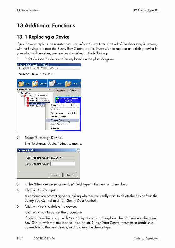
Additional Functions SMA Technologie AG
136 SDC-TEN081450 Technical Description
13 Additional Functions
13. 1 Replacing a DeviceIf you have to replace an inverter, you can inform Sunny Data Control of the device replacement, without having to detect the Sunny Boy Control again. If you wish to replace an existing device in your plant with another, proceed as described in the following.
1. Right click on the device to be replaced on the plant diagram.
2. Select "Exchange Device".
The "Exchange Device" window opens.
3. In the "New device serial number" field, type in the new serial number.
4. Click on <Exchange>.
A confirmation prompt appears, asking whether you really want to delete the device from the Sunny Boy Control and from Sunny Data Control.
5. Click on <Yes> to delete the device.
Click on <No> to cancel the procedure.
If you confirm the prompt with Yes, Sunny Data Control replaces the old device in the Sunny Boy Control with the new device. In so doing, Sunny Data Control attempts to establish a connection to the new device, and to query the device type.

Additional Functions SMA Technologie AG
Technical Description SDC-TEN081450 137
6. Wait until Sunny Data Control has successfully queried the device type.
This may take some time.
If the device type query cancels with an error message, you may have to repeat the device type update later (see section 13.1. 1 "Updating the Device Type" (Page 137)).
The device is assigned the temporary type name "??? + serial number". It is possible that during device replacement, the added device was temporarily unreachable, and the device type could thus not be ascertained.
Common Causes of Error• Incorrect serial number typed in (see name plate)
• Device is not active
13.1. 1 Updating the Device TypeWith this function, you can ascertain the device type of unsuccessfully detected devices at any subsequent point in time.
1. Right click on the device with the temporary type name "??? + Serial number" on the plant diagram.
2. Select "Update Device Type“.
Sunny Data Control attempts to establish a connection to the device, in order to ascertain the device type.
3. Wait until Sunny Data Control has successfully queried the device type.
This may take some time.
Temporary type name
Communication with a device which has a temporary type name is not possible!

Additional Functions SMA Technologie AG
138 SDC-TEN081450 Technical Description
13. 2 Open device information1. Right click on the device on the plant diagram.
2. Select "Device Information...“.
The "Device Information..." window opens.
The device information provides the following data for each respective device:
• Device name
• Device type
• Serial number
• Device ID
• Network address
• Managed devices (how many devices are connected to the device)
• Protocol used
• Channel list status
• Field position on the "Spot values" page (Device overview)
• Communication status
You can also adjust the following settings via the device information:
• Device name
• Device ID
• Network address

Additional Functions SMA Technologie AG
Technical Description SDC-TEN081450 139
13.2. 1 Setting the Device Name and Device IDYou can assign every device (Sunny Boy and Sunny Boy Control) its own device name and a two-digit device ID. By default, the device name used comprises the serial number and the device type (e.g. WR38-006 SN:2000115546).
The device names and device IDs are included in the transferred measurement files (Excel files). If you change the device name or device ID, from that time onwards, they will also change in all newly transferred measurement files for this plant.
The name of the directory with the Excel files is not changed if you change the name of a Sunny Boy Control. The directory retains the identifier "SBC+serial number“ (e.g. SBC119020033).
Changes to the device name and device ID are not automatically applied in Sunny Portal. Adjust the device name in Sunny Portal to match the changes in Sunny Data Control if desired. Refer to the Sunny Portal user manual, which can be downloaded from Sunny Portal, to learn how to change the device name in Sunny Portal.
1. Right click on the device on the plant diagram.
2. Select "Device Information...“.
The "Device Information..." window opens.
3. Click on <Change>.
The window for changing the respective setting opens.
4. Change the setting as desired.
5. Click on <Ok>.
Sunny Data Control updates the Excel lists with the measurement data. Afterwards, the window "Device Information..." is displayed with the new settings.
6. Click on <Ok>.

Additional Functions SMA Technologie AG
140 SDC-TEN081450 Technical Description
13.2. 2 Changing a Device's Network Address1. Right click on the device on the plant diagram.
2. Select "Device Information...“.
The "Device Information..." window opens.
3. Next to the address, click on <Change>.
The "Change Network Address..." window opens.
4. Change the setting as desired.
5. Click on <Set>.
6. Click on <Close>.
The "Device Information..." window is displayed again.
7. Click on <Ok>.

Additional Functions SMA Technologie AG
Technical Description SDC-TEN081450 141
13. 3 Removing Devices
1. Right click on the device on the plant diagram.
2. Select "Remove Device" or "Remove all Devices", depending on what you wish to delete.
A confirmation prompt is displayed, asking whether the deletion is to be performed.
3. If you wish to delete the device (or all devices), click on <Yes>.
Cancel with <No>.
13. 4 Adding a DeviceYou can add further sub-devices to a communication device by means of the device serial numbers.
1. Right click on a Sunny Boy on the plant diagram.
2. Select "Add Device".
The "Add Device" window opens.
3. In the "New device serial number" field, type in the serial number of the device to be added.
4. Click "Add".
Device detection starts for this serial number, and the device is searched for. Wait for the detection to end.
Directions for the deletion of inverters
If you remove an inverter from the plant tree in Sunny Data Control, this inverter is also deleted in the Sunny Boy Control!

Additional Functions SMA Technologie AG
142 SDC-TEN081450 Technical Description
13. 5 Sorting DevicesYou can either sort the devices in the plant tree according to name, or according to serial number.
1. Right click on the plant diagram window.
The menu opens.
2. Choose "Sort devices".
3. Select either "by Serial number" or "by Name.
13. 6 Creating a Color Palette for Device FieldsUpon delivery of Sunny Data Control, several palette files are included. You can create your own preferred color gradients by means of simple editing of these files, using commercially available graphics programs. The files have the following structure:
• Size: 100 x 2 pixels
• Format: BMP (Windows bitmap)
• Subdivided into upper and lower pixel rows.
- The upper pixel row is the color gradient for capacity utilization between 0 and 100 percent (first pixel = 0 percent and last pixel = 100 percent).
- The lower pixel row represents the text color with which the information is to be displayed in the device field, according to the background color (upper pixel row).
To create a palette file, proceed as follows:
1. Launch a commercially available graphics program.
2. Create a new drawing with the dimensions 100 x 2 pixels.
3. Draw the desired color gradients (see figure above).
4. Save the file in BMP format - Windows bitmap.
5. Rename the file (e.g. MyPalette.pbm).
6. Save the file in the Sunny Data Control's "Images" directory.
2 pixels
100 pixels
Upper pixel row
Lower pixel row

Additional Functions SMA Technologie AG
Technical Description SDC-TEN081450 143
13. 7 Changing the Fonts of Device FieldsYou can change the fonts of device fields (A). You can also assign each device field its own font, or change the font of a particular device type.
1. Right click on the device to be changed on the page "Spot values".
The task menu opens.
2. Choose "Change font"
3. Choose which devices are to be changed.
The window for adjusting the font opens.
4. Set the font, the font style and the font size.
5. Click on <Ok>.
13. 8 Background ImagesYou can set background images for the device overview (online display) and for the total overview. It is also possible to have different background images which alternate automatically.
Deleting or Adding a Background Image.1. Choose "Options / Settings"
The "Settings" window opens.
2. Select "Background Pictures“.
A

Additional Functions SMA Technologie AG
144 SDC-TEN081450 Technical Description
3. Click on <-> to delete the selected background picture.
The background picture is deleted.
4. To add a new background picture, click on <+>.
The window for selecting a background image opens.
PathBy default, the background pictures are found in the directory "SMA\Sunny Data Control\Images\background". You can also save your own background images there, and subsequently select them. File types bitmap or PNG can be used.
5. Select a background image, and click on <Open>.
The "Settings" window is displayed once more.
Alternation Between Different Background ImagesIf you wish to set several background images to be displayed one after the other with an interval of a defined length, you must select at least two background images.
6. To add another background picture, click on <+>.
7. In the "Timer" field, set the time in seconds after which the next background image is to be displayed.
8. To change the order in which the background pictures are to appear, select the picture and click on <Up> or <Down>.
Full Size9. If the image is to be displayed in full size (over the entire area), add a check mark beside "Full
size" by clicking on the check box.
Activating / Deactivating Background Image Display10. Add or delete the check mark next to the field "Active".
11. Click on <Ok>.
You can activate the total overview via "Spotvalues / Activate Total Overview".

Additional Functions SMA Technologie AG
Technical Description SDC-TEN081450 145
13. 9 Packet MonitorYou can enable display of the data packets in the packet monitor.
1. Choose "Extras/Packet Monitor".
The "Packet Monitor" window opens as a separate window at the lower edge of the screen, then resides in the background once you click on the Sunny Data Control interface.
2. To change the settings of the Packet Monitor, right click on the Packet Monitor window. The Packet Monitor menu opens.

Additional Functions SMA Technologie AG
146 SDC-TEN081450 Technical Description
The following settings for the Packet Monitor are possible.
• Start
Starts or ends the Packet Monitor.
• Clear list...
Deletes the list with the data packets shown.
• Save to file...
Saves the data packets in a text file.
A window opens for selection of the directory in which the text file is to be saved. The saved file is called "Pakets.txt (see example).
• Content as text
Shows the content of the column "Content" as text instead of numbers.
• Protocol Level
Here, you can select the protocol level (Level2 or Raw (Level1)).

Additional Functions SMA Technologie AG
Technical Description SDC-TEN081450 147
13. 10 Changing the Security Level (Installer Password).Sunny Data Control has two security levels: "user" and "installer". Every time the program is launched, the security level "user" is automatically restored.
You can set the security level to "installer" with the installer password, as described below. Within the security level "installer", you are able to change more parameters, and can lock and unlock the device overview. See section 13. 11 "Locking the Device Overview (Online Display)" (Page 148).
Displaying the Present Security LevelYou can call up Sunny Data Control's present security level via the menu item "? / Info..." . The "Info" window opens.
Setting the Security Level to "Installer"1. Select "Extras / Security Level“.
The window for changing the security level opens.
2. In the field "Operator", enter the word "Installer" and in the field "Password", the Installer password (provided with your Sunny Boy Control).
3. Click on <Ok>. A message is displayed, indicating that the respective security level has been set. Click on <Ok>.
Quitting the Installer Security LevelIn order to quit the installer level, leave both fields blank and click <Ok>.
Installer password
The installer password is provided with your Sunny Boy Control on a separate sheet.

Additional Functions SMA Technologie AG
148 SDC-TEN081450 Technical Description
13. 11 Locking the Device Overview (Online Display)You can lock the device overview in order to protect the display from unauthorized access. This bars the following actions in the device overview:
• Moving, adding, or deleting device fields
• Changing the devices' channel settings for the device overview
1. Select "Spot values/Online display locked", or click on the padlock (see figure above).
2. Click on <Ok> to accept the settings.
The window for changing the security level opens.
3. Type in the installer or user password (provided with your Sunny Boy Control).
4. Click on <Ok>.
A message is displayed, indicating that the installer security level has been set.
5. Click on <Ok>.
Unlock Device OverviewTo quit the installer security level, proceed as described above, and enter the installer password again.
Padlock open
Locked

Additional Functions SMA Technologie AG
Technical Description SDC-TEN081450 149
13. 12 TimeoutsNormally, you will not need to adjust the timeout settings which apply to the communication with devices. Only change the settings if you fully understand the consequences.
It may be necessary to adjust channel querying for a Sunny Central Control.
13.12. 1 Settings for the Sunny Central Control1. Choose "Options / Settings"
The "Settings" window opens.
2. Select "Timing“.
3. Choose the following settings for the Sunny Central Control.
• Archive data acquisition/Channel query: 200 s
• Query archived files/Update Storage Time: 200 s
• Device detection/First detection: 10 s
• Device detection/Further detection: 10 s
4. Click on <Ok>.
Restoring Factory SettingsTo restore the factory timeout settings, click on <Reset all>.

Troubleshooting SMA Technologie AG
150 SDC-TEN081450 Technical Description
14 Troubleshooting
14. 1 Errors in the Use of Sunny Data Control
DANGER!Risk of lethal electric shock!
• All electrical connections may only be performed by qualified electricians.
• Please follow all safety instructions listed in the inverter documentation.
No. Error description Cause
1 On the "Channel recording" page, the start and end of the recording are not visible.
• Spot value querying is not active. Activate spot value querying, as described in section 10. 9 "Activating / Deactivating Spot Value Querying" (Page 68).
2 Sunny Data Control indicates "Access denied."
Sunny Data Control indicates "The specified file could not be found."
• Another software program is using the interface (e.g. terminal).
• The PC interface is not available.
3 Device detection fails. • Under "Settings / Misc", the device detection mode is set incorrectly (see section 8.4. 1 "Narrowing the Scope of Device Detection" (Page 50)).
• The PC interface's baud rate does not match that of the Sunny Boy Control.
• The wrong transfer medium was selected.
• Sunny Boy Control is not ready for reception.
• With the transfer medium RS485, it may be the case that in the extended properties of the serial port used for the Sunny Boy Control, FIFO has not been deactivated.
4 Communication cancels while in operation.
• Data cable between PC and SBC interrupted.
5 "Cannot open file." • A data file (SDX_XXXX.xls) is already open in another application (e.g. Excel) upon data transfer. Close the respective application, and start the transfer anew.
6 "The new device type is unknown because the device is unreachable."
• At present, communication with the device is not possible. Possibly, the wrong serial number was entered, or the device is not switched on.

Troubleshooting SMA Technologie AG
Technical Description SDC-TEN081450 151
14. 2 Java Applet Error Messages
No. Error description Cause
1 "Solar server is down! Please try again later! (x)“
• 1: The Internet function in Sunny Data Control is not activated, or either the application or the SDC agent has not been started. The numeric character which follows the error message indicates the exact cause of the error:
• 2: The specified server alias name in the applet parameter ServerAlias is unknown to the SDC agent.
• 4: The Internet function in Sunny Data Control is deactivated.
2 "Connection to solar server lost! Please try again later!“
• Either the SDC agent or Sunny Data Control was stopped while a connection to the applet was in place.
3 "Too many users or solar server is down! Please try again later!“
• The maximum number of connections between the Java applet and the SDC agent has been exceeded.
4 "Unable to connect! Probably there are firewall problems!“
• The Java applet could not establish a connection to the SDC agent. This is possibly due to a firewall on the client side.

Troubleshooting SMA Technologie AG
152 SDC-TEN081450 Technical Description
14. 3 Errors in the Bluetooth Installation
No. Error description Cause
1 No devices found. • Bluetooth is not integrated into the PC, and no Bluetooth stick is connected.
• No inverters are within detection range.
• The inverter in question is using the Bluetooth ID "0" (Bluetooth off).
- Set the Bluetooth ID of the inverter to a higher number, "1". In order for the inverter to take on the new Bluetooth ID, it must be restarted (AC and DC off, as described in the inverter instructions).
• The Bluetooth stack installed is not supported by Sunny Data Control. Sunny Data Control supports, without further intervention, only stacks from Toshiba, Microsoft, BlueSoleil and Broadcom. Other Bluetooth stacks can be used via a virtual COM port.
2 Only 1 inverter is shown. • The inverters are under the Bluetooth ID "1" and therefore do not network.
- Set the Bluetooth ID of all inverters to a value between "2" and "F".
3 More inverters are shown than are in the plant.
• In this case there is a neighboring plant which is using the same Bluetooth ID.
- Use another, free Bluetooth ID for the inverters.
4 "The connection to the plant is broken".
• When this message appears, the connection of the PCs to the inverters, or to the plant, is broken. This connection will not be repaired. All other connections between the inverters are automatically repaired, even in the case of errors or interruptions, or alternative connections to other accessible inverters are searched.
- Acknowledge the failure message with <OK>.
- Open the menu "Spot values/Spot value querying".
- Click on <Activate> or use the keyboard shortcut "Ctrl+B".

Troubleshooting SMA Technologie AG
Technical Description SDC-TEN081450 153
14.3. 1 FAQ• The commissioning of an integrated Bluetooth interface in a PC was not successful.
- With Sunny Data Control it is not possible to work with the integrated Bluetooth solution or with the Bluetooth stack. Set up the virtual COM port as described in the Bluetooth stick manual.
• Which Bluetooth IDs are still free?
- Choose "Options / Settings/Communication."
- Choose "Bluetooth" from the drop-down list "Connection via".
- Click on <Settings>.
- Click on <Change>.
- Choose "Bluetooth IDs" from the "Display type" drop-down menu.
- Click on <Search>. All Bluetooth IDs in the vecinity are shown. All Bluetooth IDs not included here are presumably still free.
• How do I find out which Bluetooth ID is set on my inverter?
There are two possibilities.
- Switch off the inverter's AC circuit breaker and secure it against accidental switching on.
- Switch off the signaling contact of the supply voltage and secure it against accidental switching on (if present).
- Remove the Electronic Solar Switch ESS
- Wait until the inverter is completely deactivated. Check to see that LEDs, display and, if present, the fault sensor are off.
- Reconnect the Electronic Solar Switch ESS.
- Switch on the AC circuit breaker again.
- During the following booting procedure of the inverter, the setting of the Bluetooth ID switch is shown, among other things.
or
- Open the inverter as described in its manual.
- Read the position of the Bluetooth ID switch inside the inverter.
5 After the installation of the Bluetooth stick has been completed, the integrated Bluetooth interface does not function.
• Unfortunately SMA cannot guarantee that the installation of several sticks and stacks on a PC will not create problems. There are installations which behave dominantly, or which configure the system in such a way that competing installations no longer work.
No. Error description Cause

Troubleshooting SMA Technologie AG
154 SDC-TEN081450 Technical Description
• I have installed the Bluetooth stick's software already. How do I proceed?
- We recommend to deinstall the software and to proceed with the commissioning as described in this manual. If no functioning Bluetooth connection to the plant can be set up this way, then the Bluetooth stick's accompanying software should be reinstalled.
- After this, set up a virtual COM port, as described in the Bluetooth stick's manual.
• I cannot switch off the Bluetooth capability integrated into the PC. Can I use a stick nevertheless?
- A Bluetooth stick can probably be used parallel to an integrated Bluetooth interface.
- Set up the virtual COM port as described in the Bluetooth stick manual.
• Which Bluetooth stacks does Sunny Data Control support without further manipulation on part of the user?
- Microsoft
- Toshiba
- BlueSoleil
- BlueSoleil
Other Bluetooth stacks can be used via a virtual COM port.

Troubleshooting SMA Technologie AG
Technical Description SDC-TEN081450 155
14. 4 Setting the Language1. Choose "Options / Settings"
The "Settings" window opens.
2. Select "Language“.
3. In the drop-down list " Use Program Language", select the desired language.
4. Click on <Ok>.
Available Languages
Which languages are available depends on the language package installed.

Contact SMA Technologie AG
156 SDC-TEN081450 Technical Description
15 ContactIf you have technical problems concerning our products, please contact our Service Line.We require the following information in order to provide you with the necessary assistance:
• Type of inverters and serial numbers
• Serial number and firmware version of the communication device
• Sunny Data Control software version
SMA Solar Technology AG
Sonnenallee 1
34266 Niestetal, Germany
Tel. +49 561 9522 2499
Fax +49 561 9522 4699
www.SMA.de

SMA Technologie AG Legal Restrictions
Technical Description SDC-TEN081450 157
The information contained in this document is the property of SMA Technologie AG. Publishing its content, either partially or in full, requires the written permission of SMA Technologie AG. Any internal company copying of the document for the purposes of evaluating the product or its correct implementation is allowed and does not require permission.
Exclusion of liabilityThe general terms and conditions of delivery of SMA Technologie AG shall apply.
The content of these documents is continually checked and amended, where necessary. However, discrepancies cannot be excluded. No guarantee is made for the completeness of these documents. The latest version is available online at www.SMA.de or from the usual sales channels.
Guarantee or liability claims for damages of any kind are excluded if they are caused by one or more of the following:
• Damages during transportation
• Improper or inappropriate use of the product
• Operating the product in an unintended environment
• Operating the product whilst ignoring relevant, statutory safety regulations in the deployment location
• Ignoring safety warnings and instructions contained in all documents relevant to the product
• Operating the product under incorrect safety or protection conditions
• Altering the product or supplied software without authority
• The product malfunctions due to operating attached or neighboring devices beyond statutory limit values
• In case of unforeseen calamity or force majeure
The use of supplied software produced by SMA Technologie AG is subject to the following conditions:
• SMA Technologie AG rejects any liability for direct or indirect damages arising from the use of software developed by SMA Technologie AG. This also applies to the provision or non-provision of support activities.
• Supplied software not developed by SMA Technologie AG is subject to the respective licensing and liability agreements of the manufacturer.
SMA Factory WarrantyThe current guarantee conditions come enclosed with your device. These are also available online at www.SMA.de and can be downloaded or are available on paper from the usual sales channels if required.
TrademarksAll trademarks are recognized even if these are not marked separately. Missing designations do not mean that a product or brand is not a registered trademark.
SMA Technologie AG
Hannoversche Strasse 1-5
34266 Niestetal
Germany
Tel. +49 561 9522-0
Fax +49 561 9522-100
www.SMA.de
E-Mail: [email protected]
© 2004 to 2008 SMA Technologie AG. All rights reserved

www.SMA.deSales Solar Technology
SMA Technologie AGHannoversche Strasse 1–534266 Niestetal, GermanyTel.: +49 561 9522 4000Fax: +49 561 9522 4040Email: [email protected]: +800 SUNNYBOYFreecall: +800 78669269
Innovation in Systems Technologyfor the Success of Photovoltaics


![SDC-12/SDC-15 · 2018-01-14 · Introduction 6 SDC-12/SDC-151080pD-ILA3D Front Projector2013 User’s Manual AdditionalOptionalAccessories Replacementlamps: •FormodelsSDC-12andSDC-15[2013productionandbeyond]orderlampWC-LPU230](https://static.fdocuments.in/doc/165x107/5f30eb9530d2254a2869f490/sdc-12sdc-15-2018-01-14-introduction-6-sdc-12sdc-151080pd-ila3d-front-projector2013.jpg)