Sun StorEdge 6920 System Host Installation Software Guide ...
Sun Microsystems, Inc.www.sun.com
Submit comments about this document at: http://www.sun.com/hwdocs/feedback
Sun StorEdge™ 3510 FC ArrayQuick Installation Guide
Part No. 819-5212-11April 2006, Revision A

PleaseRecycle
Copyright © 2002–2006 Dot Hill Systems Corporation and others, 2200 Faraday Avenue, Suite 100, Carlsbad, California 92008, USA. All rights reserved.
Sun Microsystems, Inc. and Dot Hill Systems Corporation may have intellectual property rights relating to technology embodied in this product or document. In particular, and without limitation, these intellectual property rights may include one or more of the U.S. patents listed at http://www.sun.com/patents and one or more additional patents or pending patent applications in the U.S. and other countries.
This product or document is distributed under licenses restricting its use, copying distribution, and decompilation. No part of this product or document may be reproduced in any form by any means without prior written authorization of Sun and its licensors, if any.
Third-party software is copyrighted and licensed from Sun suppliers.
Parts of the product may be derived from Berkeley BSD systems, licensed from the University of California. UNIX is a registered trademark in the U.S. and in other countries, exclusively licensed through X/Open Company, Ltd.
Sun, Sun Microsystems, the Sun logo, Sun StorEdge, AnswerBook2, docs.sun.com, and Solaris are trademarks or registered trademarks of Sun Microsystems, Inc. in the U.S. and in other countries.
U.S. Government Rights—Commercial use. Government users are subject to the Sun Microsystems, Inc. standard license agreement and applicable provisions of the FAR and its supplements.
DOCUMENTATION IS PROVIDED “AS IS” AND ALL EXPRESS OR IMPLIED CONDITIONS, REPRESENTATIONS AND WARRANTIES, INCLUDING ANY IMPLIED WARRANTY OF MERCHANTABILITY, FITNESS FOR A PARTICULAR PURPOSE OR NONINFRINGEMENT, ARE DISCLAIMED, EXCEPT TO THE EXTENT THAT SUCH DISCLAIMERS ARE HELD TO BE LEGALLY INVALID.
Copyright © 2002–2006 Dot Hill Systems Corporation et d’autres, 2200 Faraday Avenue, Suite 100, Carlsbad, Californie 92008, Etats-Unis. Tous droits réservés.
Sun Microsystems, Inc. et Dot Hill Systems Corporation peuvent avoir les droits de propriété intellectuels relatants à la technologie incorporée dans le produit qui est décrit dans ce document. En particulier, et sans la limitation, ces droits de propriété intellectuels peuvent inclure un ou plus des brevets américains énumérés à http://www.sun.com/patents et un ou les brevets plus supplémentaires ou les applications de brevet en attente dans les Etats-Unis et dans les autres pays.
Ce produit ou document est protégé par un copyright et distribué avec des licences qui en restreignent l’utilisation, la copie, la distribution, et la décompilation. Aucune partie de ce produit ou document ne peut être reproduite sous aucune forme, par quelque moyen que ce soit, sans l'autorisation préalable et écrite de Sun et de ses bailleurs de licence, s’il y ena.
Le logiciel détenu par des tiers, et qui comprend la technologie relative aux polices de caractères, est protégé par un copyright et licencié par des fournisseurs de Sun.
Des parties de ce produit pourront être dérivées des systèmes Berkeley BSD licenciés par l’Université de Californie. UNIX est une marque déposée aux Etats-Unis et dans d’autres pays et licenciée exclusivement par X/Open Company, Ltd.
Sun, Sun Microsystems, le logo Sun, Sun StorEdge, AnswerBook2, docs.sun.com, et Solaris sont des marques de fabrique ou des marques déposées de Sun Microsystems, Inc. aux Etats-Unis et dans d’autres pays.
LA DOCUMENTATION EST FOURNIE “EN L’ÉTAT” ET TOUTES AUTRES CONDITIONS, DECLARATIONS ET GARANTIES EXPRESSES OU TACITES SONT FORMELLEMENT EXCLUES, DANS LA MESURE AUTORISEE PAR LA LOI APPLICABLE, Y COMPRIS NOTAMMENT TOUTE GARANTIE IMPLICITE RELATIVE A LA QUALITE MARCHANDE, A L'APTITUDE A UNE UTILISATION PARTICULIERE OU A L’ABSENCE DE CONTREFAÇON.
Contents
1. Getting Started 1–1
1.1 Refer to Your Release Notes 1–1
1.2 Site Planning 1–2
1.3 Unpacking the Array 1–2
1.4 Converting Your Front Bezel Locks So the Keys Cannot Be Removed 1–3
1.5 Mounting Your FC Array in a Rack or Cabinet 1–5
1.6 What to Do Next 1–5
2. Connecting Your FC Array 2–1
2.1 Fibre Channel Array Connections 2–2
2.2 Connecting the Chassis to an AC Power Outlet 2–3
2.3 Connecting the Chassis to DC Power Outlets 2–4
2.4 Powering Up and Checking LEDs 2–5
2.5 Reviewing Channels, Ports, and SFPs 2–6
2.5.1 Port Connectivity in a Dual-Controller Array 2–7
2.5.2 Default SFP Placement 2–8
2.5.3 Changing Your SFP Configuration 2–9
2.6 Cabling to Expansion Units 2–10
2.6.1 Setting Loop IDs on Expansion Units 2–12
2.6.2 Scaling Beyond 36 Disks 2–14
iii
2.7 Connecting Ports to Hosts 2–15
2.8 Establishing Communications With An Array 2–16
2.8.1 Determining the Default IP Address 2–17
2.8.2 Configuring the RS-232 Serial Port Connection 2–18
2.8.3 Manually Setting a Static IP Address 2–19
2.9 Setting Up Out-of-Band Management Over Ethernet 2–21
2.10 Power-On Sequence 2–22
2.11 Power-Off Sequence 2–23
iv Sun StorEdge 3510 FC Array Quick Installation Guide • April 2006
CHAPTER 1
Getting Started
This guide provides basic instructions on how to unpack and connect your Sun StorEdgeTM 3510 FC array.
This chapter includes the following topics:
■ Section 1.1, “Refer to Your Release Notes” on page 1-1■ Section 1.2, “Site Planning” on page 1-2■ Section 1.3, “Unpacking the Array” on page 1-2■ Section 1.4, “Converting Your Front Bezel Locks So the Keys Cannot Be
Removed” on page 1-3■ Section 1.5, “Mounting Your FC Array in a Rack or Cabinet” on page 1-5■ Section 1.6, “What to Do Next” on page 1-5
1.1 Refer to Your Release NotesRefer to the Sun StorEdge 3510 FC Array Release Notes for your array to see late-breaking information including required patches and supported hardware and software. The release notes and other documentation for this product are available online at:
www.sun.com/products-n-solutions/hardware/docs/Network_Storage_Solutions/Workgroup/3510
and
http://docs.sun.com/app/docs/coll/3510FCarray
1-1
1.2 Site Planning Refer to the Sun StorEdge 3000 Family Installation, Operation, and Service Manual for your array to see detailed information about preinstallation site planning and a preinstallation worksheet to fill out before you unpack and set up your Sun StorEdge FC array.
1.3 Unpacking the ArrayFollow these guidelines for unpacking the equipment.
Caution – Always use two people to remove the unit from its container, to avoid personal injury or damage to the equipment during installation. A fully loaded unit weighs approximately 60 pounds.
1. Select a suitable area for unpacking.
2. Store all packing material and boxes for possible equipment returns.
3. Check the Contents Sheet in your product package.
The Contents Sheet summarizes the standard contents for your product.
4. Compare the packing slip and the list of parts with the items you received.
If the list of parts on your packing slip does not match the items you received, or any items appear damaged, immediately notify your carrier agent and the supplier who prepared your shipment.
5. Carefully examine the cables provided in the package.
If any cable appears to be damaged, contact the Technical Service department for an immediate replacement.
6. Make sure you have provided the following cables required to complete the installation:
■ A minimum of one fiber-optic cable per host to connect a host to a RAID array; two fiber-optic cables are required for a redundant path configuration.
To obtain qualified cables, consult your Sun sales representative.
1-2 Sun StorEdge 3510 FC Array Quick Installation Guide • April 2006
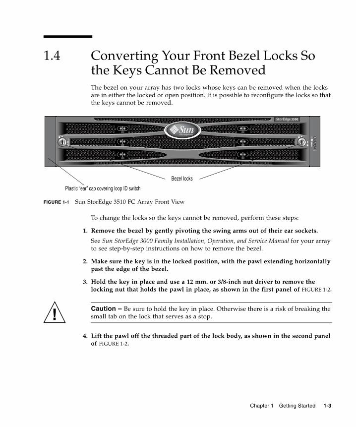
1.4 Converting Your Front Bezel Locks So the Keys Cannot Be RemovedThe bezel on your array has two locks whose keys can be removed when the locks are in either the locked or open position. It is possible to reconfigure the locks so that the keys cannot be removed.
FIGURE 1-1 Sun StorEdge 3510 FC Array Front View
To change the locks so the keys cannot be removed, perform these steps:
1. Remove the bezel by gently pivoting the swing arms out of their ear sockets.
See Sun StorEdge 3000 Family Installation, Operation, and Service Manual for your array to see step-by-step instructions on how to remove the bezel.
2. Make sure the key is in the locked position, with the pawl extending horizontally past the edge of the bezel.
3. Hold the key in place and use a 12 mm. or 3/8-inch nut driver to remove the locking nut that holds the pawl in place, as shown in the first panel of FIGURE 1-2.
Caution – Be sure to hold the key in place. Otherwise there is a risk of breaking the small tab on the lock that serves as a stop.
4. Lift the pawl off the threaded part of the lock body, as shown in the second panel of FIGURE 1-2.
Bezel locks
Plastic “ear” cap covering loop ID switch
Chapter 1 Getting Started 1-3
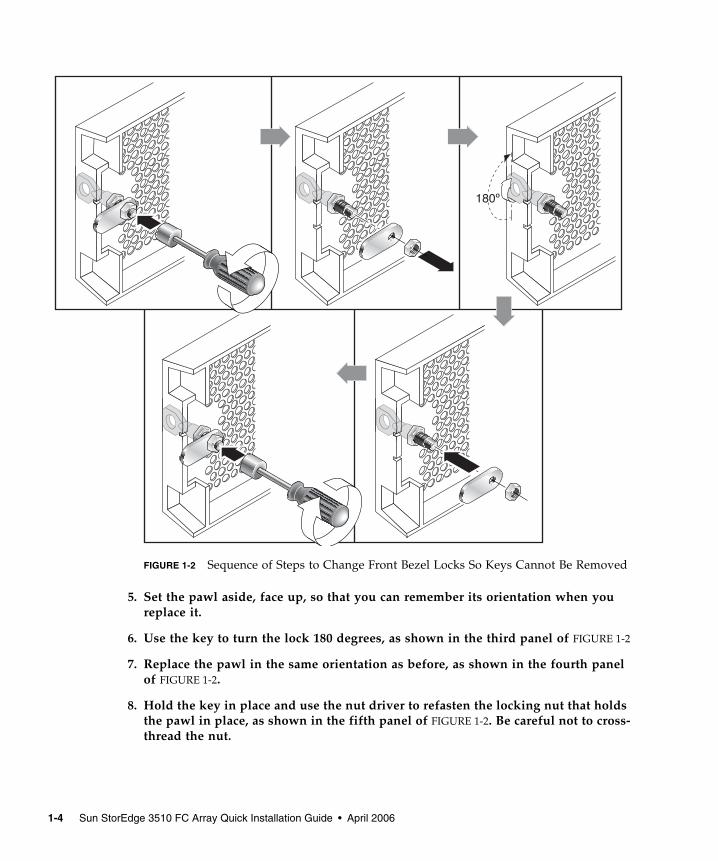
FIGURE 1-2 Sequence of Steps to Change Front Bezel Locks So Keys Cannot Be Removed
5. Set the pawl aside, face up, so that you can remember its orientation when you replace it.
6. Use the key to turn the lock 180 degrees, as shown in the third panel of FIGURE 1-2
7. Replace the pawl in the same orientation as before, as shown in the fourth panel of FIGURE 1-2.
8. Hold the key in place and use the nut driver to refasten the locking nut that holds the pawl in place, as shown in the fifth panel of FIGURE 1-2. Be careful not to cross-thread the nut.
1-4 Sun StorEdge 3510 FC Array Quick Installation Guide • April 2006
Caution – Be sure to hold the key in place. Otherwise there is a risk of breaking the small tab on the lock that serves as a stop.
9. Replace the bezel.
Note – To convert your bezel locks so that the keys can be removed, repeat this procedure.
1.5 Mounting Your FC Array in a Rack or CabinetTo physically mount your array, follow the instructions that came with your mounting kit or those found in the Sun StorEdge 3000 Family Rack Installation Guide, located on the optional product CD and on the product website.
1.6 What to Do Next1. For cabling with standard configurations, see Section , “Connecting Your FC
Array” on page 2-1.
For alternate configurations, refer to the Sun StorEdge 3000 Family Best Practices Manual.
2. After cabling is complete, print and use the Sun StorEdge 3000 Family Installation, Operation, and Service Manual for your array for first-time configuration and basic troubleshooting.
3. Optionally, install additional software from the product CD or website and print the related manuals.
Chapter 1 Getting Started 1-5

1-6 Sun StorEdge 3510 FC Array Quick Installation Guide • April 2006
CHAPTER 2
Connecting Your FC Array
This chapter describes procedures for cabling the Sun StorEdge 3510 FC array as shipped in its default configuration, and for connecting the array to power and to network devices. Refer to the Sun StorEdge 3000 Family Installation, Operation, and Service Manual for detailed configuration information.
The following topics are covered in this chapter:
■ Section 2.1, “Fibre Channel Array Connections” on page 2-2■ Section 2.2, “Connecting the Chassis to an AC Power Outlet” on page 2-3■ Section 2.3, “Connecting the Chassis to DC Power Outlets” on page 2-4■ Section 2.4, “Powering Up and Checking LEDs” on page 2-5■ Section 2.5, “Reviewing Channels, Ports, and SFPs” on page 2-6
■ Section 2.5.1, “Port Connectivity in a Dual-Controller Array” on page 2-7■ Section 2.5.2, “Default SFP Placement” on page 2-8■ Section 2.5.3, “Changing Your SFP Configuration” on page 2-9
■ Section 2.6, “Cabling to Expansion Units” on page 2-10■ Section 2.6.1, “Setting Loop IDs on Expansion Units” on page 2-12■ Section 2.6.2, “Scaling Beyond 36 Disks” on page 2-14
■ Section 2.7, “Connecting Ports to Hosts” on page 2-15■ Section 2.8, “Establishing Communications With An Array” on page 2-16
■ Section 2.8.1, “Determining the Default IP Address” on page 2-17■ Section 2.8.2, “Configuring the RS-232 Serial Port Connection” on page 2-18■ Section 2.8.3, “Manually Setting a Static IP Address” on page 2-19
■ Section 2.9, “Setting Up Out-of-Band Management Over Ethernet” on page 2-21■ Section 2.10, “Power-On Sequence” on page 2-22■ Section 2.11, “Power-Off Sequence” on page 2-23
Before you connect the Sun StorEdge 3511 SATA array to the network, position it in the rack or in a location where it will reside on the network. You can stack up to five arrays on top of each other. Do not stack more than five arrays in one stack. Do not block the air vents at the front or back of the unit. Follow all safety precautions specified in the Sun StorEdge 3000 Family Safety, Regulatory, and Compliance Manual.
2-1
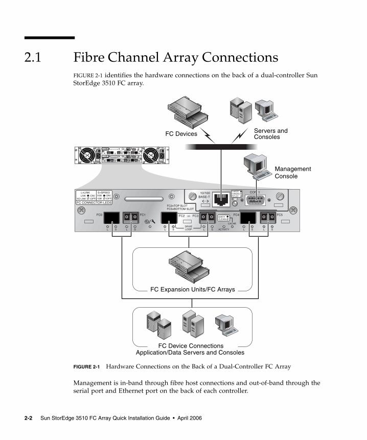
2.1 Fibre Channel Array ConnectionsFIGURE 2-1 identifies the hardware connections on the back of a dual-controller Sun StorEdge 3510 FC array.
FIGURE 2-1 Hardware Connections on the Back of a Dual-Controller FC Array
Management is in-band through fibre host connections and out-of-band through the serial port and Ethernet port on the back of each controller.
Application/Data Servers and ConsolesFC Device Connections
FC Expansion Units/FC Arrays
ManagementConsole
Servers andConsolesFC Devices
2-2 Sun StorEdge 3510 FC Array Quick Installation Guide • April 2006
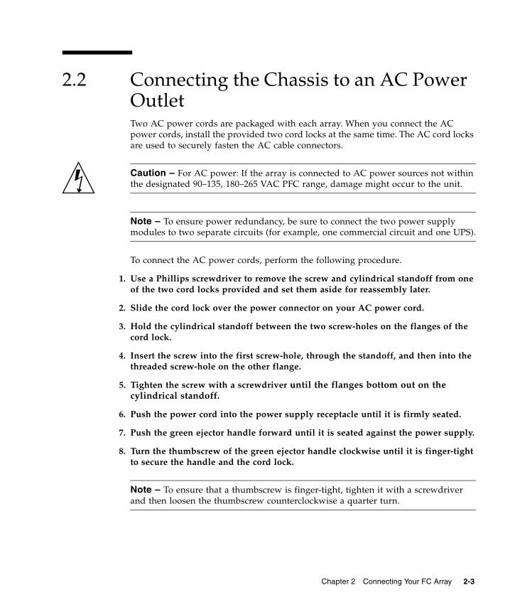
2.2 Connecting the Chassis to an AC Power OutletTwo AC power cords are packaged with each array. When you connect the AC power cords, install the provided two cord locks at the same time. The AC cord locks are used to securely fasten the AC cable connectors.
Caution – For AC power: If the array is connected to AC power sources not within the designated 90–135, 180–265 VAC PFC range, damage might occur to the unit.
Note – To ensure power redundancy, be sure to connect the two power supply modules to two separate circuits (for example, one commercial circuit and one UPS).
To connect the AC power cords, perform the following procedure.
1. Use a Phillips screwdriver to remove the screw and cylindrical standoff from one of the two cord locks provided and set them aside for reassembly later.
2. Slide the cord lock over the power connector on your AC power cord.
3. Hold the cylindrical standoff between the two screw-holes on the flanges of the cord lock.
4. Insert the screw into the first screw-hole, through the standoff, and then into the threaded screw-hole on the other flange.
5. Tighten the screw with a screwdriver until the flanges bottom out on the cylindrical standoff.
6. Push the power cord into the power supply receptacle until it is firmly seated.
7. Push the green ejector handle forward until it is seated against the power supply.
8. Turn the thumbscrew of the green ejector handle clockwise until it is finger-tight to secure the handle and the cord lock.
Note – To ensure that a thumbscrew is finger-tight, tighten it with a screwdriver and then loosen the thumbscrew counterclockwise a quarter turn.
Chapter 2 Connecting Your FC Array 2-3
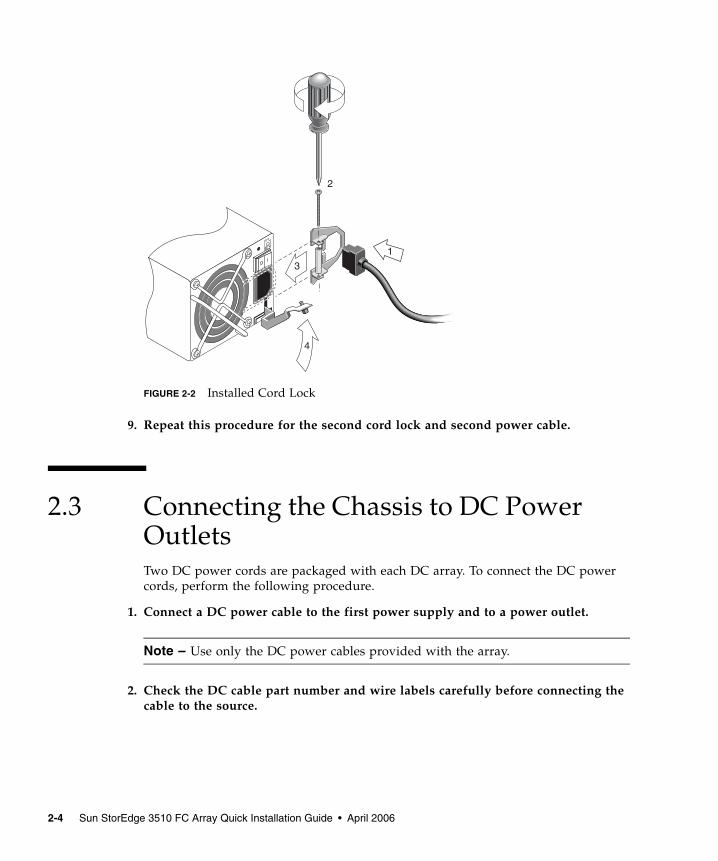
FIGURE 2-2 Installed Cord Lock
9. Repeat this procedure for the second cord lock and second power cable.
2.3 Connecting the Chassis to DC Power OutletsTwo DC power cords are packaged with each DC array. To connect the DC power cords, perform the following procedure.
1. Connect a DC power cable to the first power supply and to a power outlet.
Note – Use only the DC power cables provided with the array.
2. Check the DC cable part number and wire labels carefully before connecting the cable to the source.
1
3
2
4
2-4 Sun StorEdge 3510 FC Array Quick Installation Guide • April 2006
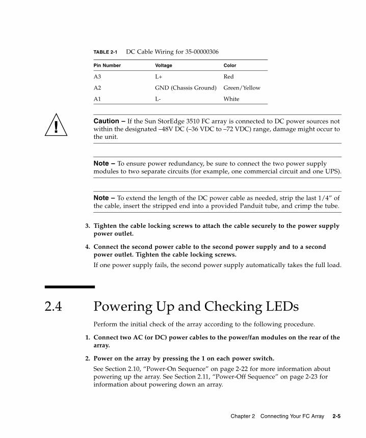
Caution – If the Sun StorEdge 3510 FC array is connected to DC power sources not within the designated –48V DC (–36 VDC to –72 VDC) range, damage might occur to the unit.
Note – To ensure power redundancy, be sure to connect the two power supply modules to two separate circuits (for example, one commercial circuit and one UPS).
Note – To extend the length of the DC power cable as needed, strip the last 1/4” of the cable, insert the stripped end into a provided Panduit tube, and crimp the tube.
3. Tighten the cable locking screws to attach the cable securely to the power supply power outlet.
4. Connect the second power cable to the second power supply and to a second power outlet. Tighten the cable locking screws.
If one power supply fails, the second power supply automatically takes the full load.
2.4 Powering Up and Checking LEDsPerform the initial check of the array according to the following procedure.
1. Connect two AC (or DC) power cables to the power/fan modules on the rear of the array.
2. Power on the array by pressing the 1 on each power switch.
See Section 2.10, “Power-On Sequence” on page 2-22 for more information about powering up the array. See Section 2.11, “Power-Off Sequence” on page 2-23 for information about powering down an array.
TABLE 2-1 DC Cable Wiring for 35-00000306
Pin Number Voltage Color
A3 L+ Red
A2 GND (Chassis Ground) Green/Yellow
A1 L- White
Chapter 2 Connecting Your FC Array 2-5
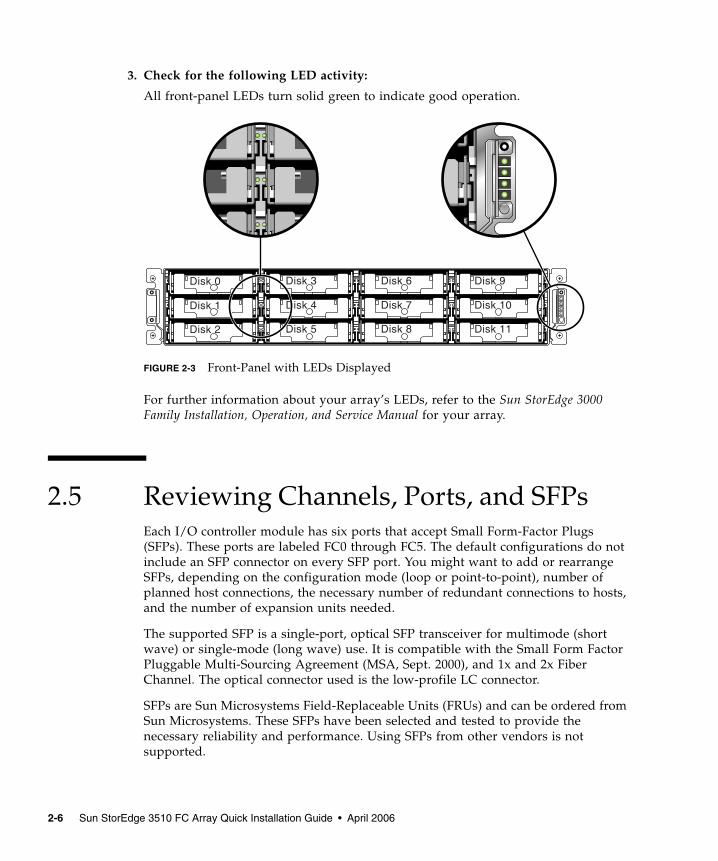
3. Check for the following LED activity:
All front-panel LEDs turn solid green to indicate good operation.
FIGURE 2-3 Front-Panel with LEDs Displayed
For further information about your array’s LEDs, refer to the Sun StorEdge 3000 Family Installation, Operation, and Service Manual for your array.
2.5 Reviewing Channels, Ports, and SFPs Each I/O controller module has six ports that accept Small Form-Factor Plugs (SFPs). These ports are labeled FC0 through FC5. The default configurations do not include an SFP connector on every SFP port. You might want to add or rearrange SFPs, depending on the configuration mode (loop or point-to-point), number of planned host connections, the necessary number of redundant connections to hosts, and the number of expansion units needed.
The supported SFP is a single-port, optical SFP transceiver for multimode (short wave) or single-mode (long wave) use. It is compatible with the Small Form Factor Pluggable Multi-Sourcing Agreement (MSA, Sept. 2000), and 1x and 2x Fiber Channel. The optical connector used is the low-profile LC connector.
SFPs are Sun Microsystems Field-Replaceable Units (FRUs) and can be ordered from Sun Microsystems. These SFPs have been selected and tested to provide the necessary reliability and performance. Using SFPs from other vendors is not supported.
Disk 0
Disk 1
Disk 2
Disk 3
Disk 4
Disk 5
Disk 6
Disk 7
Disk 8
Disk 9
Disk 10
Disk 11
2-6 Sun StorEdge 3510 FC Array Quick Installation Guide • April 2006
To see an example of an array which has SFP connectors in all the SFP ports of the RAID array and the upper expansion unit, refer to the illustration Section FIGURE 2-10, “RAID Array Attached to Two Hosts and Two Expansion Units” on page 2-11.
To review various configuration options, refer to the Sun StorEdge 3000 Family Installation, Operation, and Service Manual. Refer also to the configuration options presented in the Sun StorEdge 3000 Family Best Practices for the Sun StorEdge 3510 FC array.
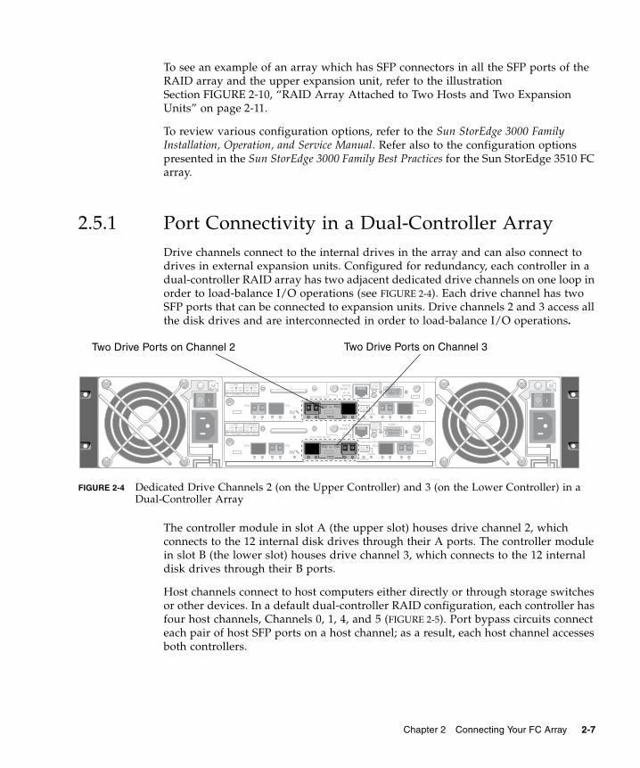
2.5.1 Port Connectivity in a Dual-Controller ArrayDrive channels connect to the internal drives in the array and can also connect to drives in external expansion units. Configured for redundancy, each controller in a dual-controller RAID array has two adjacent dedicated drive channels on one loop in order to load-balance I/O operations (see FIGURE 2-4). Each drive channel has two SFP ports that can be connected to expansion units. Drive channels 2 and 3 access all the disk drives and are interconnected in order to load-balance I/O operations.
FIGURE 2-4 Dedicated Drive Channels 2 (on the Upper Controller) and 3 (on the Lower Controller) in a Dual-Controller Array
The controller module in slot A (the upper slot) houses drive channel 2, which connects to the 12 internal disk drives through their A ports. The controller module in slot B (the lower slot) houses drive channel 3, which connects to the 12 internal disk drives through their B ports.
Host channels connect to host computers either directly or through storage switches or other devices. In a default dual-controller RAID configuration, each controller has four host channels, Channels 0, 1, 4, and 5 (FIGURE 2-5). Port bypass circuits connect each pair of host SFP ports on a host channel; as a result, each host channel accesses both controllers.
Two Drive Ports on Channel 2 Two Drive Ports on Channel 3
Chapter 2 Connecting Your FC Array 2-7
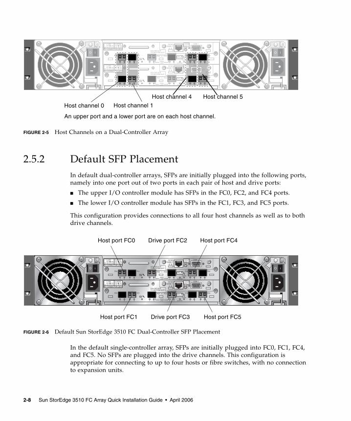
FIGURE 2-5 Host Channels on a Dual-Controller Array
2.5.2 Default SFP PlacementIn default dual-controller arrays, SFPs are initially plugged into the following ports, namely into one port out of two ports in each pair of host and drive ports:
■ The upper I/O controller module has SFPs in the FC0, FC2, and FC4 ports.
■ The lower I/O controller module has SFPs in the FC1, FC3, and FC5 ports.
This configuration provides connections to all four host channels as well as to both drive channels.
FIGURE 2-6 Default Sun StorEdge 3510 FC Dual-Controller SFP Placement
In the default single-controller array, SFPs are initially plugged into FC0, FC1, FC4, and FC5. No SFPs are plugged into the drive channels. This configuration is appropriate for connecting to up to four hosts or fibre switches, with no connection to expansion units.
Host channel 0 Host channel 1
Host channel 4 Host channel 5
An upper port and a lower port are on each host channel.
Host port FC0 Drive port FC2 Host port FC4
Host port FC1 Drive port FC3 Host port FC5
2-8 Sun StorEdge 3510 FC Array Quick Installation Guide • April 2006
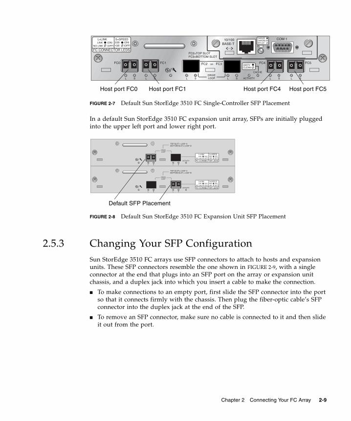
FIGURE 2-7 Default Sun StorEdge 3510 FC Single-Controller SFP Placement
In a default Sun StorEdge 3510 FC expansion unit array, SFPs are initially plugged into the upper left port and lower right port.
FIGURE 2-8 Default Sun StorEdge 3510 FC Expansion Unit SFP Placement
2.5.3 Changing Your SFP ConfigurationSun StorEdge 3510 FC arrays use SFP connectors to attach to hosts and expansion units. These SFP connectors resemble the one shown in FIGURE 2-9, with a single connector at the end that plugs into an SFP port on the array or expansion unit chassis, and a duplex jack into which you insert a cable to make the connection.
■ To make connections to an empty port, first slide the SFP connector into the port so that it connects firmly with the chassis. Then plug the fiber-optic cable’s SFP connector into the duplex jack at the end of the SFP.
■ To remove an SFP connector, make sure no cable is connected to it and then slide it out from the port.
Host port FC0 Host port FC4 Host port FC5Host port FC1
Default SFP Placement
Chapter 2 Connecting Your FC Array 2-9
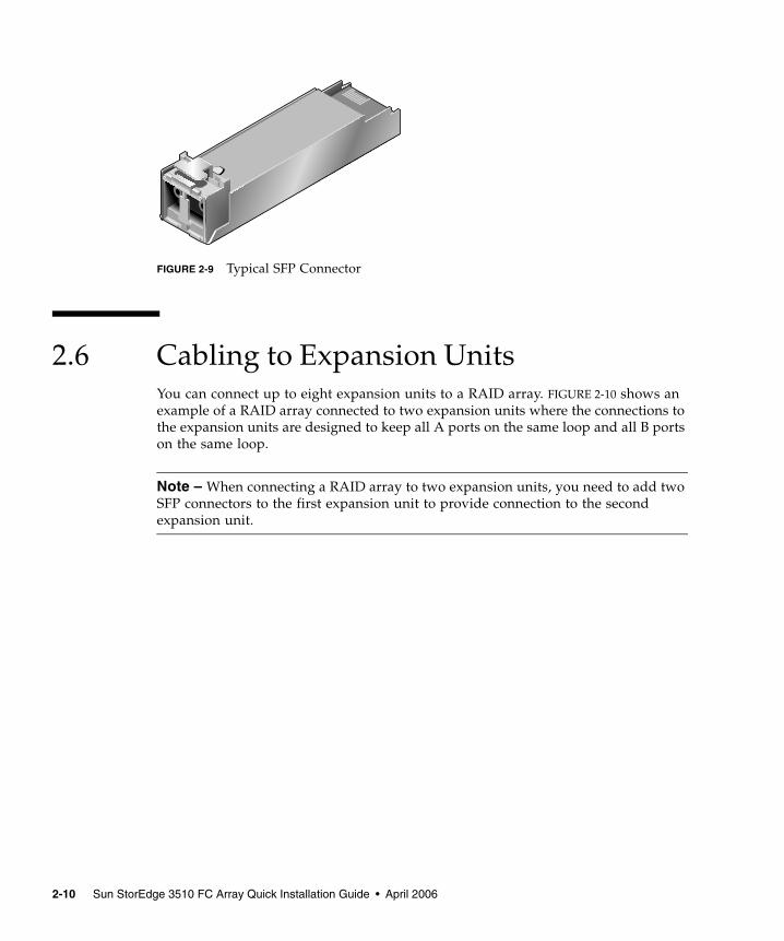
FIGURE 2-9 Typical SFP Connector
2.6 Cabling to Expansion UnitsYou can connect up to eight expansion units to a RAID array. FIGURE 2-10 shows an example of a RAID array connected to two expansion units where the connections to the expansion units are designed to keep all A ports on the same loop and all B ports on the same loop.
Note – When connecting a RAID array to two expansion units, you need to add two SFP connectors to the first expansion unit to provide connection to the second expansion unit.
2-10 Sun StorEdge 3510 FC Array Quick Installation Guide • April 2006
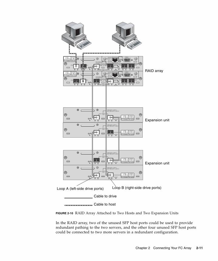
FIGURE 2-10 RAID Array Attached to Two Hosts and Two Expansion Units
In the RAID array, two of the unused SFP host ports could be used to provide redundant pathing to the two servers, and the other four unused SFP host ports could be connected to two more servers in a redundant configuration.
Cable to drive
RAID array
Cable to host
Expansion unit
Expansion unit
Loop A (left-side drive ports) Loop B (right-side drive ports)
Chapter 2 Connecting Your FC Array 2-11
Similarly, you can connect a maximum of eight expansion units to other channels (which are separate from channels 2 and 3) if you configure Channels 0, 1, 4 or 5 as drive channels.
Refer to the Sun StorEdge 3000 Family Best Practices Manual for additional configuration options and for information on scaling beyond 36 disks.
2.6.1 Setting Loop IDs on Expansion Units When an expansion unit is attached to a RAID array, unique, hard-assigned loop IDs are assigned to each expansion unit drive. A loop ID is the decimal version of an AL_PA. The lowest number loop ID is the lowest priority address on the loop.
On the left front side of each RAID array and expansion unit, an ID switch is used to set the loop IDs for the disk drives to a different range of values so that the same IDs are not repeated on the same loop.
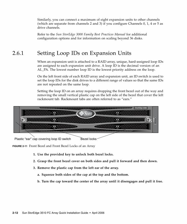
Setting the loop ID on an array requires dropping the front bezel out of the way and removing the small vertical plastic cap on the left side of the bezel that cover the left rackmount tab. Rackmount tabs are often referred to as “ears.”
FIGURE 2-11 Front Bezel and Front Bezel Locks of an Array
1. Use the provided key to unlock both bezel locks.
2. Grasp the front bezel cover on both sides and pull it forward and then down.
3. Remove the plastic cap from the left ear of the array.
a. Squeeze both sides of the cap at the top and the bottom.
b. Turn the cap toward the center of the array until it disengages and pull it free.
Bezel locksPlastic “ear” cap covering loop ID switch
2-12 Sun StorEdge 3510 FC Array Quick Installation Guide • April 2006
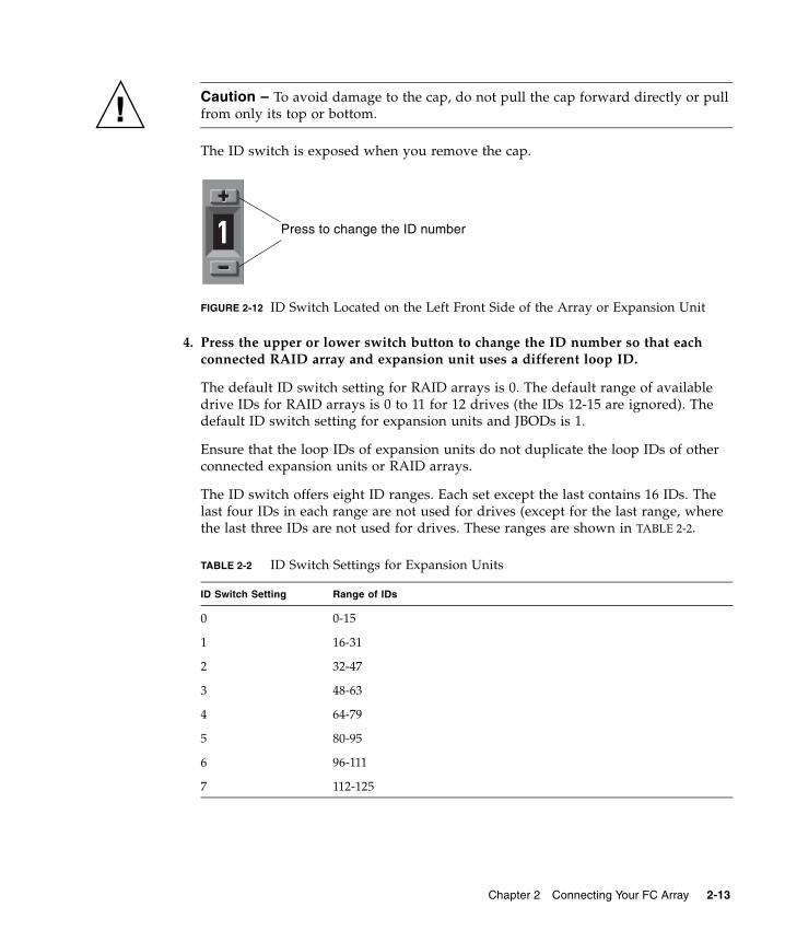
Caution – To avoid damage to the cap, do not pull the cap forward directly or pull from only its top or bottom.
The ID switch is exposed when you remove the cap.
FIGURE 2-12 ID Switch Located on the Left Front Side of the Array or Expansion Unit
4. Press the upper or lower switch button to change the ID number so that each connected RAID array and expansion unit uses a different loop ID.
The default ID switch setting for RAID arrays is 0. The default range of available drive IDs for RAID arrays is 0 to 11 for 12 drives (the IDs 12-15 are ignored). The default ID switch setting for expansion units and JBODs is 1.
Ensure that the loop IDs of expansion units do not duplicate the loop IDs of other connected expansion units or RAID arrays.
The ID switch offers eight ID ranges. Each set except the last contains 16 IDs. The last four IDs in each range are not used for drives (except for the last range, where the last three IDs are not used for drives. These ranges are shown in TABLE 2-2.
TABLE 2-2 ID Switch Settings for Expansion Units
ID Switch Setting Range of IDs
0 0-15
1 16-31
2 32-47
3 48-63
4 64-79
5 80-95
6 96-111
7 112-125
Press to change the ID number
Chapter 2 Connecting Your FC Array 2-13
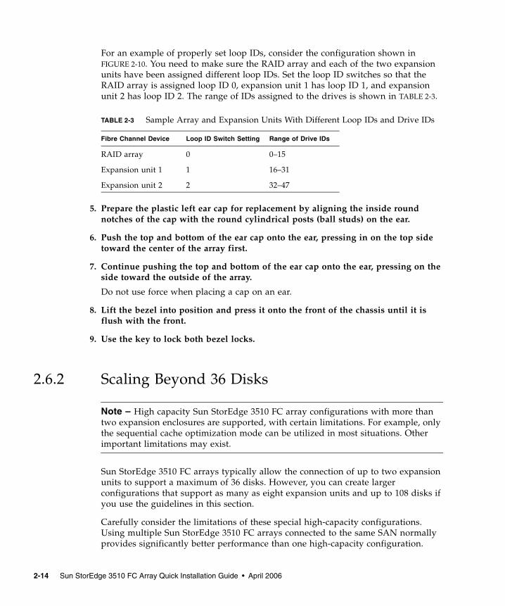
For an example of properly set loop IDs, consider the configuration shown in FIGURE 2-10. You need to make sure the RAID array and each of the two expansion units have been assigned different loop IDs. Set the loop ID switches so that the RAID array is assigned loop ID 0, expansion unit 1 has loop ID 1, and expansion unit 2 has loop ID 2. The range of IDs assigned to the drives is shown in TABLE 2-3.
5. Prepare the plastic left ear cap for replacement by aligning the inside round notches of the cap with the round cylindrical posts (ball studs) on the ear.
6. Push the top and bottom of the ear cap onto the ear, pressing in on the top side toward the center of the array first.
7. Continue pushing the top and bottom of the ear cap onto the ear, pressing on the side toward the outside of the array.
Do not use force when placing a cap on an ear.
8. Lift the bezel into position and press it onto the front of the chassis until it is flush with the front.
9. Use the key to lock both bezel locks.
2.6.2 Scaling Beyond 36 Disks
Note – High capacity Sun StorEdge 3510 FC array configurations with more than two expansion enclosures are supported, with certain limitations. For example, only the sequential cache optimization mode can be utilized in most situations. Other important limitations may exist.
Sun StorEdge 3510 FC arrays typically allow the connection of up to two expansion units to support a maximum of 36 disks. However, you can create larger configurations that support as many as eight expansion units and up to 108 disks if you use the guidelines in this section.
Carefully consider the limitations of these special high-capacity configurations. Using multiple Sun StorEdge 3510 FC arrays connected to the same SAN normally provides significantly better performance than one high-capacity configuration.
TABLE 2-3 Sample Array and Expansion Units With Different Loop IDs and Drive IDs
Fibre Channel Device Loop ID Switch Setting Range of Drive IDs
RAID array 0 0–15
Expansion unit 1 1 16–31
Expansion unit 2 2 32–47
2-14 Sun StorEdge 3510 FC Array Quick Installation Guide • April 2006
Limiting the maximum number of expansion units to 7 provides much greater configuration flexibility. Doing so enables using up to 96 disks.
Refer to the Sun StorEdge 3000 Family Best Practices Manual for the Sun StorEdge 3510 FC array for cabling diagrams for configurations ranging from three to eight expansion units.
Note – Large configurations may require the use of one or more optional extended-length cables, part number X9732A. Other items may also be required. Refer to the Sun StorEdge 3000 Family FRU Installation Guide for information about supported cables, SFPs, and other user-replaceable items.
Caution – To avoid drive assignment conflicts, make sure that each connected array and expansion unit uses a different loop ID, as described Section 2.6.1, “Setting Loop IDs on Expansion Units” on page 2-12.
2.7 Connecting Ports to HostsIn a default array configuration, channels 0, 1, 4, and 5 are host channels, so you can directly connect an FC array to four host computers. SFP connectors are plugged into channels 0 and 4 on the upper controller and channels 1 and 5 on the lower controller for this purpose.
If you want to connect an FC array to more than four host computers without changing the default configuration, you can connect these four host channels to ports on storage switches in a Storage Area Network (SAN) configuration.
Note – Connecting the Sun StorEdge 3510 RAID array to Fibre Channel HBAs on the same channel that use different speeds (1 Gbyte & 2 Gbyte) is not supported. You can, however, mix 1-Gbyte and 2-Gbyte Fibre Channel HBAs on different channels. This limitation is due to the design of the Sun StorEdge 3510 RAID array's port bypass circuitry and the inability of Fibre Channel to support auto-negotiation in a multi-drop loop configuration.
Use fiber-optic cables to connect from one to four host channels to Fibre Channel host adapters on your host computers or to other devices such as storage switches:
1. Connect a fiber-optic cable to a host bus adapter (HBA) or FC port on each host or storage switch you want to connect to the array.
Chapter 2 Connecting Your FC Array 2-15

2. Connect the SFP connector at the other end of each fiber-optic cable to a host channel SFP connector on the back of the array.
If there is no SFP connector in the port you want to use, first insert an SFP connector into the port as described in Section 2.5.3, “Changing Your SFP Configuration” on page 2-9.
2.8 Establishing Communications With An ArrayBefore you can configure an array, you must establish one or more communication links between at least one host and an array. You can use any combination of the array’s RS-232 COM (serial) port, the Ethernet port, and the in-band data connection between the host and the array.
■ A direct RS-232 port connection guarantees that a host can communicate with a RAID array even if the array’s IP address changes or is unknown, or if the TCP/IP network suffers a temporary outage.
See Section 2.8.2, “Configuring the RS-232 Serial Port Connection” on page 2-18 for more information. For pinout information, refer to the Sun StorEdge 3000 Family Installation, Operation, and Service Manual for your array.
When you connect via the serial port, you immediately access the controller firmware application, a management program embedded in the firmware.
Note – If you are connected through a serial port connection (including a Solaris tip session) rather than through a telnet session, it is possible that when a controller is inserted, deasserted, or failed over, unwanted “garbage” characters can be displayed or the firmware application can appear to be frozen. This is due to the controller negotiation that occurs during a power-up or restart cycle. In most cases using the Ctrl-L keyboard shortcut corrects this problem. If Ctrl-L does not properly refresh the screen, it might be necessary to restart the session.
■ Your array ships with the Dynamic Host Configuration Protocol (DHCP) TCP/IP network support protocol enabled. If your network uses a DHCP server to automatically allocate IP addresses to attached devices, as soon as the RAID array is powered up, an IP address is assigned to it.
You can use this IP address to monitor and manage the array’s firmware through telnet sessions. See Section 2.9, “Setting Up Out-of-Band Management Over Ethernet” on page 2-21 for information about setting up a telnet session. The out-of-band management tools are:
■ The host-based Sun StorEdge Configuration Service software.
2-16 Sun StorEdge 3510 FC Array Quick Installation Guide • April 2006
■ The host-based Sun StorEdge Command-Line Interface (CLI).
■ The firmware application you access when you use the telnet command to connect to the IP address of the controller.
Note – You can install the latest Sun StorEdge 3000 Family CLI or Configuration Service software from the CD for your product or download the software from the Sun Download Center. See your product release notes for details.
Note – By default, the CLI and the Sun StorEdge Configuration console automatically access in-band all arrays connected to the host server where the software is installed.
■ A static IP address enables you to use telnet or other out-of-band management sessions to manage the array with no risk of a DHCP server changing its IP address.
See Section 2.8.3, “Manually Setting a Static IP Address” on page 2-19 for information.
2.8.1 Determining the Default IP Address When the array is first powered up, the default IP address setting uses the IP address assigned by a DHCP server.
Note – If you do not use a DHCP server with the array, you will not have an IP address and will need to use the serial port connection to create an IP address. See Section 2.8.2, “Configuring the RS-232 Serial Port Connection” on page 2-18.
If the RAID array is connected to a network with an active DHCP server, you can determine the IP address assigned to the array in several ways:
■ Access the firmware and follow the procedure Section 2.8.2, “Configuring the RS-232 Serial Port Connection” on page 2-18.
When you connect via the serial port, you immediately access the controller firmware application, a management program embedded in the firmware.
■ If you already installed the Sun StorEdge 3000 Family CLI program, use the show network-parameters CLI command.
If the RAID controller is not on a network connected to an active DHCP server, an IP address of 0.0.0.0 is displayed. Refer to the Sun StorEdge 3000 Family CLI User’s Guide for more information.
Chapter 2 Connecting Your FC Array 2-17
■ If you already installed the Sun StorEdge Configuration Service program, use the Change Network Settings window to display the IP address of the array. Refer to the “Updating the Configuration” chapter in Sun StorEdge Configuration Service User’s Guide for more information.
Event messages sent as SNMP traps to the email address you specify also contain the IP address of the array from which it is sent. Refer to the “Configuration Parameters” chapter in the Sun StorEdge 3000 Family RAID Firmware User’s Guide for more information.
Once you have determined the RAID controller’s IP address using one of these methods, you can establish a telnet session to that IP address.
Caution – However, because of the dynamic nature of DHCP-assigned IP addresses, the RAID array’s IP address might change in the event of a controller reset, a network outage, or if the DHCP server is rebooted. If this happens, telnet sessions to the previous IP address can no longer communicate with the array, and it is necessary to use one of the methods described above to determine the new IP address.
If you do not have an active DHCP server on the same network as the RAID array, or if you prefer to have a static IP address, use the procedures in Section 2.8.3, “Manually Setting a Static IP Address” on page 2-19.
2.8.2 Configuring the RS-232 Serial Port ConnectionThe RS-232 COM (serial) port on either controller module can be used to configure and monitor the RAID array using the controller firmware. It can be connected to a VT100 terminal, terminal emulation program, terminal server, or the serial port of a server.
Note – When you connect through a serial port connection, you might need to refresh the screen to display the RAID firmware Main Menu properly. Press Ctrl-L to refresh the screen.
1. Use a null modem serial cable to connect the COM port of the RAID array to the serial port on a host workstation.
A null modem serial cable is included in your package.
2. Set the serial port parameters on the workstation as follows:
■ 38,400 baud■ 8 bit■ 1 stop bit
2-18 Sun StorEdge 3510 FC Array Quick Installation Guide • April 2006
■ No parity
If you need information on how to set up a Solaris tip session, how to set up serial port parameters on a specific operating system, or information on cable pinouts, refer to the Sun StorEdge 3000 Family Installation, Operation, and Service Manual for your array.
3. Access the array through the COM serial port and select the VT100 terminal emulation to access the Main Menu.
4. Check the DHCP IP address and confirm that it is valid.
From the firmware Main Menu choose Configuration Parameters → Communication Parameters → Internet Protocol (TCP/IP).
If the RAID controller is not on a network connected to an active DHCP server, “DHCP Client” is displayed rather than a DHCP-assigned IP address. Refer to the “Configuration Parameters” chapter in the Sun StorEdge 3000 Family RAID Firmware User’s Guide for more information.
5. If you need to reset the IP address or make a static IP address, refer to Section 2.8.3, “Manually Setting a Static IP Address” on page 2-19.
6. Configure the array.
■ To configure the array through the firmware application, refer to the Sun StorEdge 3000 Family RAID Firmware User’s Guide.
■ To configure the array through out-of-band management, refer to Section 2.9, “Setting Up Out-of-Band Management Over Ethernet” on page 2-21.
2.8.3 Manually Setting a Static IP AddressYou can manually set an array’s IP address using the controller’s firmware by typing values for the IP address, the subnet mask, and IP address of the gateway. If your network uses a Reverse Address Resolution Protocol (RARP) server or a Dynamic Host Configuration Protocol (DHCP) server to automatically configure IP information for devices on the network, you can specify the appropriate protocol instead of typing the information manually.
Chapter 2 Connecting Your FC Array 2-19
Note – If you assign an IP address to an array to manage it out-of-band, for security reasons consider using an IP address on a private network rather than a publicly routable network. Using the controller firmware to set a password for the controller limits unauthorized access to the array. Changing the firmware’s Network Protocol Support settings can provide further security by disabling the ability to remotely connect to the array using individual protocols such as HTTP, HTTPS, telnet, FTP, and SSH. Refer to the “Communication Parameters” section of the Sun StorEdge 3000 Family RAID Firmware User’s Guide for more information.
To set the IP address, subnet mask, and gateway address of the RAID controller, perform the following steps.
1. Access the array through the COM port on the I/O controller module or through a telnet session to the existing IP address.
2. From the controller firmware’s Main Menu, choose “view and edit Configuration parameters → Communication Parameters → Internet Protocol (TCP/IP).”
3. Select the chip hardware address and MAC address that is displayed.
4. Choose “Set IP Address → Address.”
5. Type the desired IP address, subnet mask (if it is not automatically supplied), and gateway address, choosing each menu option in turn, backspacing over any existing entries.
If your network sets IP addresses using a RARP server and you prefer using it to using a static IP address, type RARP rather than an IP address and do not type a subnet mask or gateway address. If your network sets IP addresses using a DHCP server and you prefer using it to using a static IP address, type DHCP rather than an IP address and do not type a subnet mask or gateway address.
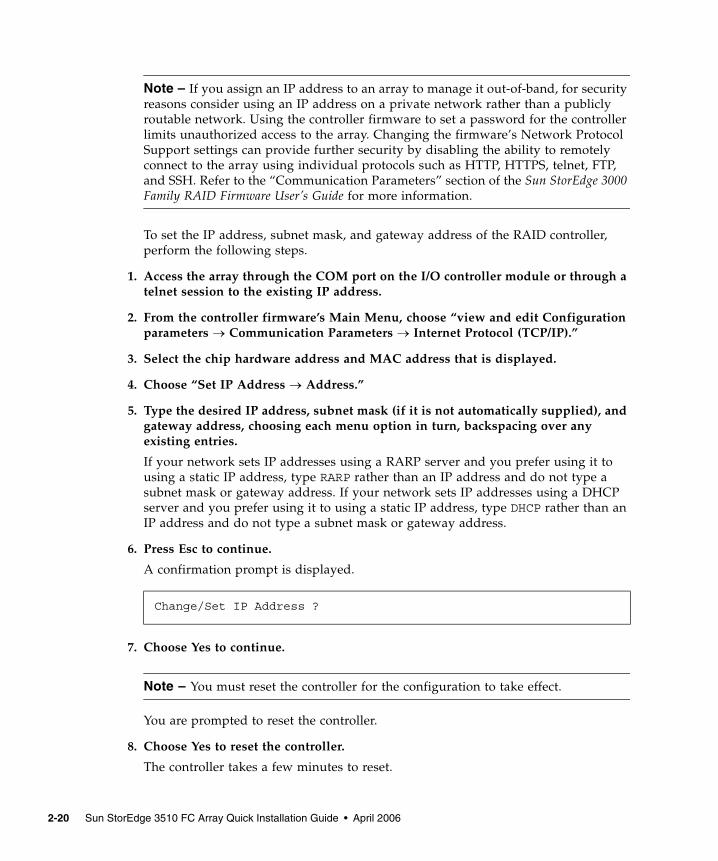
6. Press Esc to continue.
A confirmation prompt is displayed.
7. Choose Yes to continue.
Note – You must reset the controller for the configuration to take effect.
You are prompted to reset the controller.
8. Choose Yes to reset the controller.
The controller takes a few minutes to reset.
Change/Set IP Address ?
2-20 Sun StorEdge 3510 FC Array Quick Installation Guide • April 2006
2.9 Setting Up Out-of-Band Management Over EthernetThe controller Ethernet port offers interactive out-of-band management through the following interfaces:
■ The Sun StorEdge Configuration Service application. Refer to the Sun StorEdge 3000 Family Configuration Service User’s Guide for details.
■ The Sun StorEdge Command-Line Interface (CLI). Refer to the Sun StorEdge 3000 Family CLI User’s Guide for details.
■ The firmware application you access when you use the telnet command to connect to the IP address of the controller.
Using an Ethernet connection, you can configure and monitor RAID arrays and expansion units remotely by using the telnet command to access the firmware application on the array and by using the Sun StorEdge Configuration Service or Sun StorEdge CLI software.
Note – If you assign an IP address to an array to manage it out-of-band, for security reasons consider using an IP address on a private network rather than a publicly routable network. Using the controller firmware to set a password for the controller limits unauthorized access to the array. Changing the firmware’s Network Protocol Support settings can provide further security by disabling the ability to remotely connect to the array using individual protocols such as HTTP, HTTPS, telnet, FTP, and SSH. Refer to the “Communication Parameters” section of the Sun StorEdge 3000 Family RAID Firmware User’s Guide for more information.
1. To access the RAID array over an Ethernet connection, first connect the RAID array’s Ethernet port on each controller to the network.
Note – Sun StorEdge 3000 family arrays require at least CAT-5 Ethernet cable.
Note – In a dual-controller RAID array, be sure to connect both Ethernet ports to the network. This provides failover if one controller fails.
2. Establish the IP address of the RAID array, as described in Section 2.8, “Establishing Communications With An Array” on page 2-16.
3. To use the firmware application program from the host server, connect to the IP address of the RAID array controller with the following command:
Chapter 2 Connecting Your FC Array 2-21
Note – Alternatively, you can use the Solaris operating system tip command or a terminal emulation program to access the firmware application program. See Section 2.8.2, “Configuring the RS-232 Serial Port Connection” on page 2-18 for more information.
4. Press Ctrl-L to refresh the screen and view the Main Menu.
Note – If you reset the controller during a telnet session, you are disconnected from the RAID array. Use the telnet command to login to the array again.
To connect the Sun StorEdge Configuration Service program (on a host server) to a RAID array that has an IP address, refer to the out-of-band management instructions in the Sun StorEdge 3000 Family Configuration Service User’s Guide.
The same document’s “Email and SNMP” appendix provides information about configuring Sun StorEdge Configuration Service software to use Simple Network Management Protocol (SNMP) traps and Management Information Bases (MIBs) to provide information to other out-of-band enterprise management software. The “Monitoring the Array” chapter explains the use of Sun StorEdge Configuration Service agents to redirect event messages into host system logs.
You can also enable the controller firmware to send event messages using SNMP. Refer to the “Configuration Parameters” chapter in the Sun StorEdge 3000 Family RAID Firmware User’s Guide for more information.
2.10 Power-On SequencePower on the equipment in the following order, so that the host computer discovers all connected arrays:
1. Expansion units
2. RAID array
3. Host computers
# telnet IP-address
2-22 Sun StorEdge 3510 FC Array Quick Installation Guide • April 2006
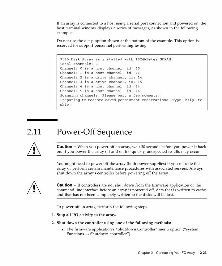
If an array is connected to a host using a serial port connection and powered on, the host terminal window displays a series of messages, as shown in the following example.
Do not use the skip option shown at the bottom of the example. This option is reserved for support personnel performing testing.
2.11 Power-Off Sequence
Caution – When you power off an array, wait 30 seconds before you power it back on. If you power the array off and on too quickly, unexpected results may occur.
You might need to power off the array (both power supplies) if you relocate the array or perform certain maintenance procedures with associated servers. Always shut down the array’s controller before powering off the array.
Caution – If controllers are not shut down from the firmware application or the command line interface before an array is powered off, data that is written to cache and that has not been completely written to the disks will be lost.
To power off an array, perform the following steps.
1. Stop all I/O activity to the array.
2. Shut down the controller using one of the following methods:
■ The firmware application’s “Shutdown Controller” menu option (“system Functions → Shutdown controller”)
3510 Disk Array is installed with 1024MBytes SDRAMTotal channels: 6Channel: 0 is a host channel, id: 40Channel: 1 is a host channel, id: 41Channel: 2 is a drive channel, id: 14Channel: 3 is a drive channel, id: 15Channel: 4 is a host channel, id: 44Channel: 5 is a host channel, id: 46Scanning channels. Please wait a few moments!Preparing to restore saved persistent reservations. Type 'skip' to skip:
Chapter 2 Connecting Your FC Array 2-23
■ The Sun StorEdge CLI shutdown controller command
These methods first halt all I/O activity, and then write cache contents to the drives.
3. Power off both power supply/fan modules.
See Section 2.10, “Power-On Sequence” on page 2-22 for information about turning the array back on.
2-24 Sun StorEdge 3510 FC Array Quick Installation Guide • April 2006