Sun Java System Communications Services 6 2005Q1 ...
376
Sun Java ™ System Communications Services 6 Deployment Planning Guide 2005Q1 Sun Microsystems, Inc. 4150 Network Circle Santa Clara, CA 95054 U.S.A. Part No: 819-0063-10
Transcript of Sun Java System Communications Services 6 2005Q1 ...

Sun Java™ System
Communications Services 6Deployment Planning Guide
2005Q1
Sun Microsystems, Inc.4150 Network CircleSanta Clara, CA 95054U.S.A.
Part No: 819-0063-10

Copyright © 2005 Sun Microsystems, Inc., 4150 Network Circle, Santa Clara, California 95054, U.S.A. All rights reserved.Sun Microsystems, Inc. has intellectual property rights relating to technology embodied in the product that is described in this document. In particular, and withoutlimitation, these intellectual property rights may include one or more of the U.S. patents listed at http://www.sun.com/patents and one or more additional patentsor pending patent applications in the U.S. and in other countries.THIS PRODUCT CONTAINS CONFIDENTIAL INFORMATION AND TRADE SECRETS OF SUN MICROSYSTEMS, INC. USE, DISCLOSURE ORREPRODUCTION IS PROHIBITED WITHOUT THE PRIOR EXPRESS WRITTEN PERMISSION OF SUN MICROSYSTEMS, INC.U.S. Government Rights - Commercial software. Government users are subject to the Sun Microsystems, Inc. standard license agreement and applicable provisions ofthe FAR and its supplements.This distribution may include materials developed by third parties.Parts of the product may be derived from Berkeley BSD systems, licensed from the University of California. UNIX is a registered trademark in the U.S. and in othercountries, exclusively licensed through X/Open Company, Ltd.Sun, Sun Microsystems, the Sun logo, Java, Solaris, JDK, Java Naming and Directory Interface, JavaMail, JavaHelp, J2SE, iPlanet, the Duke logo, the Java Coffee Cuplogo, the Solaris logo, the SunTone Certified logo and the Sun ONE logo are trademarks or registered trademarks of Sun Microsystems, Inc. in the U.S. and othercountries.All SPARC trademarks are used under license and are trademarks or registered trademarks of SPARC International, Inc. in the U.S. and other countries. Productsbearing SPARC trademarks are based upon architecture developed by Sun Microsystems, Inc.Legato and the Legato logo are registered trademarks, and Legato NetWorker, are trademarks or registered trademarks of Legato Systems, Inc. The NetscapeCommunications Corp logo is a trademark or registered trademark of Netscape Communications Corporation.The OPEN LOOK and Sun(TM) Graphical User Interface was developed by Sun Microsystems, Inc. for its users and licensees. Sun acknowledges the pioneeringefforts of Xerox in researching and developing the concept of visual or graphical user interfaces for the computer industry. Sun holds a non-exclusive license fromXerox to the Xerox Graphical User Interface, which license also covers Sun's licensees who implement OPEN LOOK GUIs and otherwise comply with Sun's writtenlicense agreements.This product includes software developed by Computing Services at Carnegie Mellon University (http://www.cmu.edu/computing/).Products covered by and information contained in this service manual are controlled by U.S. Export Control laws and may be subject to the export or import laws inother countries. Nuclear, missile, chemical biological weapons or nuclear maritime end uses or end users, whether direct or indirect, are strictly prohibited. Export orreexport to countries subject to U.S. embargo or to entities identified on U.S. export exclusion lists, including, but not limited to, the denied persons and speciallydesignated nationals lists is strictly prohibited.DOCUMENTATION IS PROVIDED “AS IS” AND ALL EXPRESS OR IMPLIED CONDITIONS, REPRESENTATIONS AND WARRANTIES, INCLUDING ANYIMPLIED WARRANTY OF MERCHANTABILITY, FITNESS FOR A PARTICULAR PURPOSE OR NON-INFRINGEMENT, ARE DISCLAIMED, EXCEPT TO THEEXTENT THAT SUCH DISCLAIMERS ARE HELD TO BE LEGALLY INVALID._______________________________________________________________________________________________________________Copyright © 2005 Sun Microsystems, Inc., 4150 Network Circle, Santa Clara, California 95054, Etats-Unis. Tous droits réservés.Sun Microsystems, Inc. détient les droits de propriété intellectuels relatifs à la technologie incorporée dans le produit qui est décrit dans ce document. En particulier,et ce sans limitation, ces droits de propriété intellectuelle peuvent inclure un ou plusieurs des brevets américains listés à l'adresse http://www.sun.com/patents etun ou des brevets supplémentaires ou des applications de brevet en attente aux Etats - Unis et dans les autres pays.CE PRODUIT CONTIENT DES INFORMATIONS CONFIDENTIELLES ET DES SECRETS COMMERCIAUX DE SUN MICROSYSTEMS, INC. SON UTILISATION,SA DIVULGATION ET SA REPRODUCTION SONT INTERDITES SANS L AUTORISATION EXPRESSE, ECRITE ET PREALABLE DE SUN MICROSYSTEMS,INC.Cette distribution peut comprendre des composants développés par des tierces parties.Des parties de ce produit peuvent être dérivées des systèmes Berkeley BSD licenciés par l'Université de Californie. UNIX est une marque déposée aux Etats-Uniset dans d'autres pays et licenciée exclusivement par X/Open Company, Ltd.Sun, Sun Microsystems, le logo Sun, Java, Solaris, JDK, Java Naming and Directory Interface, JavaMail, JavaHelp, J2SE, iPlanet, le logo Duke, le logo Java Coffee Cup,le logo Solaris, le logo SunTone Certified et le logo Sun[tm] ONE sont des marques de fabrique ou des marques déposées de Sun Microsystems, Inc. aux Etats-Unis etdans d'autres pays.Toutes les marques SPARC sont utilisées sous licence et sont des marques de fabrique ou des marques déposées de SPARC International, Inc. aux Etats-Unis et dansd'autres pays. Les produits portant les marques SPARC sont basés sur une architecture développée par Sun Microsystems, Inc.Legato, le logo Legato, et Legato NetWorker sont des marques de fabrique ou des marques déposées de Legato Systems, Inc. Le logo Netscape Communications Corpest une marque de fabrique ou une marque déposée de Netscape Communications Corporation.L'interface d'utilisation graphique OPEN LOOK et Sun(TM) a été développée par Sun Microsystems, Inc. pour ses utilisateurs et licenciés. Sun reconnaît les efforts depionniers de Xerox pour la recherche et le développement du concept des interfaces d'utilisation visuelle ou graphique pour l'industrie de l'informatique. Sun détientune license non exclusive de Xerox sur l'interface d'utilisation graphique Xerox, cette licence couvrant également les licenciés de Sun qui mettent en place l'interfaced'utilisation graphique OPEN LOOK et qui, en outre, se conforment aux licences écrites de Sun.Ce produit comprend du logiciel dévelopé par Computing Services à Carnegie Mellon University (http://www.cmu.edu/computing/).Les produits qui font l'objet de ce manuel d'entretien et les informations qu'il contient sont regis par la legislation americaine en matiere de controle des exportationset peuvent etre soumis au droit d'autres pays dans le domaine des exportations et importations. Les utilisations finales, ou utilisateurs finaux, pour des armesnucleaires, des missiles, des armes biologiques et chimiques ou du nucleaire maritime, directement ou indirectement, sont strictement interdites. Les exportations oureexportations vers des pays sous embargo des Etats-Unis, ou vers des entites figurant sur les listes d'exclusion d'exportation americaines, y compris, mais de manierenon exclusive, la liste de personnes qui font objet d'un ordre de ne pas participer, d'une facon directe ou indirecte, aux exportations des produits ou des services quisont regi par la legislation americaine en matiere de controle des exportations et la liste de ressortissants specifiquement designes, sont rigoureusement interdites.LA DOCUMENTATION EST FOURNIE “EN L'ETAT” ET TOUTES AUTRES CONDITIONS, DECLARATIONS ET GARANTIES EXPRESSES OU TACITES SONTFORMELLEMENT EXCLUES, DANS LA MESURE AUTORISEE PAR LA LOI APPLICABLE, Y COMPRIS NOTAMMENT TOUTE GARANTIE IMPLICITERELATIVE A LA QUALITE MARCHANDE, A L'APTITUDE A UNE UTILISATION PARTICULIERE OU A L'ABSENCE DE CONTREFACON.

3
Contents
List of Figures . . . . . . . . . . . . . . . . . . . . . . . . . . . . . . . . . . . . . . . . . . . . . . . . . . . . . . . . . . . . . . . . 15
List of Tables . . . . . . . . . . . . . . . . . . . . . . . . . . . . . . . . . . . . . . . . . . . . . . . . . . . . . . . . . . . . . . . . . 17
Preface . . . . . . . . . . . . . . . . . . . . . . . . . . . . . . . . . . . . . . . . . . . . . . . . . . . . . . . . . . . . . . . . . . . . . . 19
Typographic Conventions . . . . . . . . . . . . . . . . . . . . . . . . . . . . . . . . . . . . . . . . . . . . . . . . . . . . . . . . . . . . 22Symbols . . . . . . . . . . . . . . . . . . . . . . . . . . . . . . . . . . . . . . . . . . . . . . . . . . . . . . . . . . . . . . . . . . . . . . . . . . . . 23Default Paths and File Names . . . . . . . . . . . . . . . . . . . . . . . . . . . . . . . . . . . . . . . . . . . . . . . . . . . . . . . . . 24Shell Prompts . . . . . . . . . . . . . . . . . . . . . . . . . . . . . . . . . . . . . . . . . . . . . . . . . . . . . . . . . . . . . . . . . . . . . . . 24Books in This Documentation Set . . . . . . . . . . . . . . . . . . . . . . . . . . . . . . . . . . . . . . . . . . . . . . . . . . . . . . 25Other Server Documentation . . . . . . . . . . . . . . . . . . . . . . . . . . . . . . . . . . . . . . . . . . . . . . . . . . . . . . . . . . 25
Part I Deployment Planning Overview . . . . . . . . . . . . . . . . . . . . . . . . . . . . . . . . . . . . . . . . . . 29
Chapter 1 Introduction to Deploying Communications Services . . . . . . . . . . . . . . . . . . . . . 31Communications Services Overview . . . . . . . . . . . . . . . . . . . . . . . . . . . . . . . . . . . . . . . . . . . . . . . . . . . . . . 31
About Messaging Server . . . . . . . . . . . . . . . . . . . . . . . . . . . . . . . . . . . . . . . . . . . . . . . . . . . . . . . . . . . . . . 32About Calendar Server . . . . . . . . . . . . . . . . . . . . . . . . . . . . . . . . . . . . . . . . . . . . . . . . . . . . . . . . . . . . . . . 33About Instant Messaging . . . . . . . . . . . . . . . . . . . . . . . . . . . . . . . . . . . . . . . . . . . . . . . . . . . . . . . . . . . . . 33About Communications Express . . . . . . . . . . . . . . . . . . . . . . . . . . . . . . . . . . . . . . . . . . . . . . . . . . . . . . . 34About Synchronization . . . . . . . . . . . . . . . . . . . . . . . . . . . . . . . . . . . . . . . . . . . . . . . . . . . . . . . . . . . . . . . 34About Connector for Microsoft Outlook . . . . . . . . . . . . . . . . . . . . . . . . . . . . . . . . . . . . . . . . . . . . . . . . 35Communications Services Component Product Dependencies . . . . . . . . . . . . . . . . . . . . . . . . . . . . . 35
How Communications Services Satisfy Business Needs . . . . . . . . . . . . . . . . . . . . . . . . . . . . . . . . . . . . . 36How Messaging Server Satisfies Business Needs . . . . . . . . . . . . . . . . . . . . . . . . . . . . . . . . . . . . . . . . . 36How Calendar Server Satisfies Business Needs . . . . . . . . . . . . . . . . . . . . . . . . . . . . . . . . . . . . . . . . . . 36How Instant Messaging Satisfies Business Needs . . . . . . . . . . . . . . . . . . . . . . . . . . . . . . . . . . . . . . . . 37How Communications Express Satisfies Business Needs . . . . . . . . . . . . . . . . . . . . . . . . . . . . . . . . . . 37Summary of Communications Services Benefits . . . . . . . . . . . . . . . . . . . . . . . . . . . . . . . . . . . . . . . . . 37

4 Communications Services 6 2005Q1 • Deployment Planning Guide
Making the Communications Services Deployment Highly Available . . . . . . . . . . . . . . . . . . . . . . . 38Using Portal Server with Communications Services . . . . . . . . . . . . . . . . . . . . . . . . . . . . . . . . . . . . . . 39
Understanding the Deployment Process . . . . . . . . . . . . . . . . . . . . . . . . . . . . . . . . . . . . . . . . . . . . . . . . . . . 40Analyzing Business Requirements . . . . . . . . . . . . . . . . . . . . . . . . . . . . . . . . . . . . . . . . . . . . . . . . . . . . . 41Analyzing Technical Requirements . . . . . . . . . . . . . . . . . . . . . . . . . . . . . . . . . . . . . . . . . . . . . . . . . . . . 41Designing the Logical Architecture . . . . . . . . . . . . . . . . . . . . . . . . . . . . . . . . . . . . . . . . . . . . . . . . . . . . 41Designing the Deployment Architecture . . . . . . . . . . . . . . . . . . . . . . . . . . . . . . . . . . . . . . . . . . . . . . . . 42Implementing the Deployment . . . . . . . . . . . . . . . . . . . . . . . . . . . . . . . . . . . . . . . . . . . . . . . . . . . . . . . . 43
Chapter 2 Analyzing Your Communications Services Requirements . . . . . . . . . . . . . . . . . . 45Identifying Deployment Goals . . . . . . . . . . . . . . . . . . . . . . . . . . . . . . . . . . . . . . . . . . . . . . . . . . . . . . . . . . . 45
Defining Business Requirements . . . . . . . . . . . . . . . . . . . . . . . . . . . . . . . . . . . . . . . . . . . . . . . . . . . . . . . 46Operational Requirements . . . . . . . . . . . . . . . . . . . . . . . . . . . . . . . . . . . . . . . . . . . . . . . . . . . . . . . . . 46Culture and Politics . . . . . . . . . . . . . . . . . . . . . . . . . . . . . . . . . . . . . . . . . . . . . . . . . . . . . . . . . . . . . . . 46
Defining Technical Requirements . . . . . . . . . . . . . . . . . . . . . . . . . . . . . . . . . . . . . . . . . . . . . . . . . . . . . . 47Supporting Existing Usage Patterns . . . . . . . . . . . . . . . . . . . . . . . . . . . . . . . . . . . . . . . . . . . . . . . . . 47Site Distribution . . . . . . . . . . . . . . . . . . . . . . . . . . . . . . . . . . . . . . . . . . . . . . . . . . . . . . . . . . . . . . . . . . 48Network . . . . . . . . . . . . . . . . . . . . . . . . . . . . . . . . . . . . . . . . . . . . . . . . . . . . . . . . . . . . . . . . . . . . . . . . . 48Existing Infrastructure . . . . . . . . . . . . . . . . . . . . . . . . . . . . . . . . . . . . . . . . . . . . . . . . . . . . . . . . . . . . . 48Support Personnel . . . . . . . . . . . . . . . . . . . . . . . . . . . . . . . . . . . . . . . . . . . . . . . . . . . . . . . . . . . . . . . . 48
Defining Financial Requirements . . . . . . . . . . . . . . . . . . . . . . . . . . . . . . . . . . . . . . . . . . . . . . . . . . . . . . 49Defining Service Level Agreements (SLAs) . . . . . . . . . . . . . . . . . . . . . . . . . . . . . . . . . . . . . . . . . . . . . . 49
Determining Project Goals . . . . . . . . . . . . . . . . . . . . . . . . . . . . . . . . . . . . . . . . . . . . . . . . . . . . . . . . . . . . . . . 50Planning for Growth . . . . . . . . . . . . . . . . . . . . . . . . . . . . . . . . . . . . . . . . . . . . . . . . . . . . . . . . . . . . . . . . . 50
Understanding Total Cost of Ownership . . . . . . . . . . . . . . . . . . . . . . . . . . . . . . . . . . . . . . . . . . . . . 51
Chapter 3 Understanding Product Requirements and Considerations . . . . . . . . . . . . . . . . . 53Planning for Various Components . . . . . . . . . . . . . . . . . . . . . . . . . . . . . . . . . . . . . . . . . . . . . . . . . . . . . . . . 54
Understanding Service Components and Service Tiers . . . . . . . . . . . . . . . . . . . . . . . . . . . . . . . . . . . . 55LDAP Directory Information Tree Requirements . . . . . . . . . . . . . . . . . . . . . . . . . . . . . . . . . . . . . . . . . . . 57
Changes in the DIT Structure . . . . . . . . . . . . . . . . . . . . . . . . . . . . . . . . . . . . . . . . . . . . . . . . . . . . . . . . . . 57Benefits of a One-Tree DIT Structure . . . . . . . . . . . . . . . . . . . . . . . . . . . . . . . . . . . . . . . . . . . . . . . . . . . 58
Schema Requirements . . . . . . . . . . . . . . . . . . . . . . . . . . . . . . . . . . . . . . . . . . . . . . . . . . . . . . . . . . . . . . . . . . 61Directory Server Considerations . . . . . . . . . . . . . . . . . . . . . . . . . . . . . . . . . . . . . . . . . . . . . . . . . . . . . . . . . . 62
Directory Server and Tiered Architecture Considerations . . . . . . . . . . . . . . . . . . . . . . . . . . . . . . . . . 63Directory Server Topology Considerations . . . . . . . . . . . . . . . . . . . . . . . . . . . . . . . . . . . . . . . . . . . . . . 63Directory Server Capacity Planning . . . . . . . . . . . . . . . . . . . . . . . . . . . . . . . . . . . . . . . . . . . . . . . . . . . . 64Directory Server and Calendar Server Interaction Considerations . . . . . . . . . . . . . . . . . . . . . . . . . . 64Directory Server and Personal Address Book Considerations . . . . . . . . . . . . . . . . . . . . . . . . . . . . . . 65
Messaging Server Considerations . . . . . . . . . . . . . . . . . . . . . . . . . . . . . . . . . . . . . . . . . . . . . . . . . . . . . . . . 65Calendar Server Considerations . . . . . . . . . . . . . . . . . . . . . . . . . . . . . . . . . . . . . . . . . . . . . . . . . . . . . . . . . . 66Instant Messaging Considerations . . . . . . . . . . . . . . . . . . . . . . . . . . . . . . . . . . . . . . . . . . . . . . . . . . . . . . . . 68
Contents 5
Portal Server Considerations . . . . . . . . . . . . . . . . . . . . . . . . . . . . . . . . . . . . . . . . . . . . . . . . . . . . . . . . . . . . . 69Connector for Microsoft Outlook Considerations . . . . . . . . . . . . . . . . . . . . . . . . . . . . . . . . . . . . . . . . . . . 69
Connector for Microsoft Outlook Component Product Dependencies . . . . . . . . . . . . . . . . . . . . . . . 70Migrating Sun ONE Calendar Server Data . . . . . . . . . . . . . . . . . . . . . . . . . . . . . . . . . . . . . . . . . . . . . . 70Migrating Exchange Server Data . . . . . . . . . . . . . . . . . . . . . . . . . . . . . . . . . . . . . . . . . . . . . . . . . . . . . . . 70
Communications Express Considerations . . . . . . . . . . . . . . . . . . . . . . . . . . . . . . . . . . . . . . . . . . . . . . . . . 71S/MIME Considerations . . . . . . . . . . . . . . . . . . . . . . . . . . . . . . . . . . . . . . . . . . . . . . . . . . . . . . . . . . . . . 71
Chapter 4 Determining Your Network Infrastructure Needs . . . . . . . . . . . . . . . . . . . . . . . . . 73Understanding Your Existing Network . . . . . . . . . . . . . . . . . . . . . . . . . . . . . . . . . . . . . . . . . . . . . . . . . . . . 73Understanding Network Infrastructure Components . . . . . . . . . . . . . . . . . . . . . . . . . . . . . . . . . . . . . . . 74
Routers and Switches . . . . . . . . . . . . . . . . . . . . . . . . . . . . . . . . . . . . . . . . . . . . . . . . . . . . . . . . . . . . . . . . 74Firewalls . . . . . . . . . . . . . . . . . . . . . . . . . . . . . . . . . . . . . . . . . . . . . . . . . . . . . . . . . . . . . . . . . . . . . . . . . . . 75Load Balancers . . . . . . . . . . . . . . . . . . . . . . . . . . . . . . . . . . . . . . . . . . . . . . . . . . . . . . . . . . . . . . . . . . . . . . 75Storage Area Networks (SANs) . . . . . . . . . . . . . . . . . . . . . . . . . . . . . . . . . . . . . . . . . . . . . . . . . . . . . . . . 76Domain Name System (DNS) . . . . . . . . . . . . . . . . . . . . . . . . . . . . . . . . . . . . . . . . . . . . . . . . . . . . . . . . . 76
Planning Your Network Infrastructure Layout . . . . . . . . . . . . . . . . . . . . . . . . . . . . . . . . . . . . . . . . . . . . . 77Demilitarized Zone (DMZ) . . . . . . . . . . . . . . . . . . . . . . . . . . . . . . . . . . . . . . . . . . . . . . . . . . . . . . . . . . . 77Intranet . . . . . . . . . . . . . . . . . . . . . . . . . . . . . . . . . . . . . . . . . . . . . . . . . . . . . . . . . . . . . . . . . . . . . . . . . . . . 78Internal Network . . . . . . . . . . . . . . . . . . . . . . . . . . . . . . . . . . . . . . . . . . . . . . . . . . . . . . . . . . . . . . . . . . . . 78Proxies . . . . . . . . . . . . . . . . . . . . . . . . . . . . . . . . . . . . . . . . . . . . . . . . . . . . . . . . . . . . . . . . . . . . . . . . . . . . . 79Firewall Configuration . . . . . . . . . . . . . . . . . . . . . . . . . . . . . . . . . . . . . . . . . . . . . . . . . . . . . . . . . . . . . . . 79Mobile Users . . . . . . . . . . . . . . . . . . . . . . . . . . . . . . . . . . . . . . . . . . . . . . . . . . . . . . . . . . . . . . . . . . . . . . . . 80
Chapter 5 Developing a Communications Services Logical Architecture . . . . . . . . . . . . . . 81Communications Services Deployment Logical Architectures Overview . . . . . . . . . . . . . . . . . . . . . . . 81
Single-tiered Logical Architecture for One Host . . . . . . . . . . . . . . . . . . . . . . . . . . . . . . . . . . . . . . . . . 82Single-tiered Logical Architecture for Multiple Hosts . . . . . . . . . . . . . . . . . . . . . . . . . . . . . . . . . . . . . 83Single-tiered Distributed Logical Architecture . . . . . . . . . . . . . . . . . . . . . . . . . . . . . . . . . . . . . . . . . . . 84Two-tiered Logical Architecture . . . . . . . . . . . . . . . . . . . . . . . . . . . . . . . . . . . . . . . . . . . . . . . . . . . . . . . 86Edge Logical Architecture . . . . . . . . . . . . . . . . . . . . . . . . . . . . . . . . . . . . . . . . . . . . . . . . . . . . . . . . . . . . 88
Edge Architecture Design Recommendations . . . . . . . . . . . . . . . . . . . . . . . . . . . . . . . . . . . . . . . . . 90Benefits of a Single-tiered Architecture . . . . . . . . . . . . . . . . . . . . . . . . . . . . . . . . . . . . . . . . . . . . . . . . . 90Benefits of a Two-tiered Architecture . . . . . . . . . . . . . . . . . . . . . . . . . . . . . . . . . . . . . . . . . . . . . . . . . . . 91
Horizontal Scalability Strategy . . . . . . . . . . . . . . . . . . . . . . . . . . . . . . . . . . . . . . . . . . . . . . . . . . . . . . . . . . . 93Scaling Front-end and Back-end Services . . . . . . . . . . . . . . . . . . . . . . . . . . . . . . . . . . . . . . . . . . . . . . . 93
Other Deployment Issues . . . . . . . . . . . . . . . . . . . . . . . . . . . . . . . . . . . . . . . . . . . . . . . . . . . . . . . . . . . . . . . 94Implementing Local Message Transfer Protocol (LMTP) for Messaging Server . . . . . . . . . . . . . . . 94Implementing Realtime Blackhole List (RBL) . . . . . . . . . . . . . . . . . . . . . . . . . . . . . . . . . . . . . . . . . . . . 94Using Logical Service Names . . . . . . . . . . . . . . . . . . . . . . . . . . . . . . . . . . . . . . . . . . . . . . . . . . . . . . . . . 95

6 Communications Services 6 2005Q1 • Deployment Planning Guide
Chapter 6 Designing for Service Availability . . . . . . . . . . . . . . . . . . . . . . . . . . . . . . . . . . . . . . 97High Availability Solutions Overview . . . . . . . . . . . . . . . . . . . . . . . . . . . . . . . . . . . . . . . . . . . . . . . . . . . . 98
Automatic System Reconfiguration (ASR) . . . . . . . . . . . . . . . . . . . . . . . . . . . . . . . . . . . . . . . . . . . . . . 98Directory Server and High Availability . . . . . . . . . . . . . . . . . . . . . . . . . . . . . . . . . . . . . . . . . . . . . . . . . . . . 99Application Server and High Availability . . . . . . . . . . . . . . . . . . . . . . . . . . . . . . . . . . . . . . . . . . . . . . . . 100Messaging Server and Calendar Server and High Availability . . . . . . . . . . . . . . . . . . . . . . . . . . . . . . . 101Instant Messaging and Availability . . . . . . . . . . . . . . . . . . . . . . . . . . . . . . . . . . . . . . . . . . . . . . . . . . . . . . 101
Using Multiple Instant Messaging Multiplexors . . . . . . . . . . . . . . . . . . . . . . . . . . . . . . . . . . . . . . . . 102Using the Instant Messaging Watchdog Process . . . . . . . . . . . . . . . . . . . . . . . . . . . . . . . . . . . . . . . . 102
Using Enabling Techniques and Technologies . . . . . . . . . . . . . . . . . . . . . . . . . . . . . . . . . . . . . . . . . . . . . 102Using Load Balancers . . . . . . . . . . . . . . . . . . . . . . . . . . . . . . . . . . . . . . . . . . . . . . . . . . . . . . . . . . . . . . . 102Using Directory Proxy Server . . . . . . . . . . . . . . . . . . . . . . . . . . . . . . . . . . . . . . . . . . . . . . . . . . . . . . . . 103Using Replica Role Promotion . . . . . . . . . . . . . . . . . . . . . . . . . . . . . . . . . . . . . . . . . . . . . . . . . . . . . . . . 103
Locating High Availability Product Reference Information . . . . . . . . . . . . . . . . . . . . . . . . . . . . . . . . . 104Understanding Remote Site Failover . . . . . . . . . . . . . . . . . . . . . . . . . . . . . . . . . . . . . . . . . . . . . . . . . . . . . 104
Questions for Remote Site Failover . . . . . . . . . . . . . . . . . . . . . . . . . . . . . . . . . . . . . . . . . . . . . . . . . . . . 106
Chapter 7 Designing for Security . . . . . . . . . . . . . . . . . . . . . . . . . . . . . . . . . . . . . . . . . . . . . . 109Communications Services Security Overview . . . . . . . . . . . . . . . . . . . . . . . . . . . . . . . . . . . . . . . . . . . . . 109Creating a Security Strategy . . . . . . . . . . . . . . . . . . . . . . . . . . . . . . . . . . . . . . . . . . . . . . . . . . . . . . . . . . . . 110
Physical Security . . . . . . . . . . . . . . . . . . . . . . . . . . . . . . . . . . . . . . . . . . . . . . . . . . . . . . . . . . . . . . . . . . . 111Server Security . . . . . . . . . . . . . . . . . . . . . . . . . . . . . . . . . . . . . . . . . . . . . . . . . . . . . . . . . . . . . . . . . . . . . 111Operating System Security . . . . . . . . . . . . . . . . . . . . . . . . . . . . . . . . . . . . . . . . . . . . . . . . . . . . . . . . . . . 112Network Security . . . . . . . . . . . . . . . . . . . . . . . . . . . . . . . . . . . . . . . . . . . . . . . . . . . . . . . . . . . . . . . . . . . 112Messaging Security . . . . . . . . . . . . . . . . . . . . . . . . . . . . . . . . . . . . . . . . . . . . . . . . . . . . . . . . . . . . . . . . . 113Application Security . . . . . . . . . . . . . . . . . . . . . . . . . . . . . . . . . . . . . . . . . . . . . . . . . . . . . . . . . . . . . . . . 113
Implementing Secure Connections . . . . . . . . . . . . . . . . . . . . . . . . . . . . . . . . . . . . . . . . . . . . . . . . . 114Implementing Secure Connections Using Two Different Certificate Authorities (CAs) . . . . . 115
Understanding Security Misconceptions . . . . . . . . . . . . . . . . . . . . . . . . . . . . . . . . . . . . . . . . . . . . . . . . . 116Other Security Resources . . . . . . . . . . . . . . . . . . . . . . . . . . . . . . . . . . . . . . . . . . . . . . . . . . . . . . . . . . . . . . . 117
Chapter 8 Understanding Schema and Provisioning Options . . . . . . . . . . . . . . . . . . . . . . . 119Understanding Schema Choices . . . . . . . . . . . . . . . . . . . . . . . . . . . . . . . . . . . . . . . . . . . . . . . . . . . . . . . . . 119
Understanding Messaging Server Schema Choices . . . . . . . . . . . . . . . . . . . . . . . . . . . . . . . . . . . . . . 119Deciding Which Schema to Use for Messaging Server . . . . . . . . . . . . . . . . . . . . . . . . . . . . . . . . . 120LDAP Schema 1 and Messaging Server . . . . . . . . . . . . . . . . . . . . . . . . . . . . . . . . . . . . . . . . . . . . . 120LDAP Schema 2 (Native Mode) and Messaging Server . . . . . . . . . . . . . . . . . . . . . . . . . . . . . . . . 121LDAP Schema 2 Compatibility Mode and Messaging Server . . . . . . . . . . . . . . . . . . . . . . . . . . 122
Understanding Calendar Server Schema Choices . . . . . . . . . . . . . . . . . . . . . . . . . . . . . . . . . . . . . . . 122Deciding Which Schema to Use for Calendar Server . . . . . . . . . . . . . . . . . . . . . . . . . . . . . . . . . . 123LDAP Schema 1 and Calendar Server . . . . . . . . . . . . . . . . . . . . . . . . . . . . . . . . . . . . . . . . . . . . . . . 123LDAP Schema 2 (Native Mode) and Calendar Server . . . . . . . . . . . . . . . . . . . . . . . . . . . . . . . . . 124LDAP Schema 2 Compatibility Mode and Calendar Server . . . . . . . . . . . . . . . . . . . . . . . . . . . . 125

Contents 7
Understanding Provisioning Tools . . . . . . . . . . . . . . . . . . . . . . . . . . . . . . . . . . . . . . . . . . . . . . . . . . . . . . 125Understanding Messaging Server Provisioning Tools . . . . . . . . . . . . . . . . . . . . . . . . . . . . . . . . . . . . 125
Sun ONE Delegated Administrator for Messaging . . . . . . . . . . . . . . . . . . . . . . . . . . . . . . . . . . . . 126LDAP Provisioning Tools for Messaging Server . . . . . . . . . . . . . . . . . . . . . . . . . . . . . . . . . . . . . . 126Delegated Administrator and Messaging Server . . . . . . . . . . . . . . . . . . . . . . . . . . . . . . . . . . . . . 126Comparing Messaging Server Provisioning Tool Options . . . . . . . . . . . . . . . . . . . . . . . . . . . . . 127
Understanding Calendar Server Provisioning Tools . . . . . . . . . . . . . . . . . . . . . . . . . . . . . . . . . . . . . 129LDAP Provisioning Tools for Calendar Server . . . . . . . . . . . . . . . . . . . . . . . . . . . . . . . . . . . . . . . 129Delegated Administrator and Calendar Server . . . . . . . . . . . . . . . . . . . . . . . . . . . . . . . . . . . . . . . 129Comparing Calendar Server Provisioning Tool Options . . . . . . . . . . . . . . . . . . . . . . . . . . . . . . . 130
Part II Deploying Messaging Server . . . . . . . . . . . . . . . . . . . . . . . . . . . . . . . . . . . . . . . . . . 133
Chapter 9 Introduction to Messaging Server Software . . . . . . . . . . . . . . . . . . . . . . . . . . . . 135What Is a Messaging System? . . . . . . . . . . . . . . . . . . . . . . . . . . . . . . . . . . . . . . . . . . . . . . . . . . . . . . . . . . . 135Messaging Server Support for Standards and Functionality . . . . . . . . . . . . . . . . . . . . . . . . . . . . . . . . . 136
Support for Standard Protocols . . . . . . . . . . . . . . . . . . . . . . . . . . . . . . . . . . . . . . . . . . . . . . . . . . . . . . . 136Support for Hosted Domains . . . . . . . . . . . . . . . . . . . . . . . . . . . . . . . . . . . . . . . . . . . . . . . . . . . . . . . . . 137Support for User Provisioning . . . . . . . . . . . . . . . . . . . . . . . . . . . . . . . . . . . . . . . . . . . . . . . . . . . . . . . . 137Support for Unified Messaging . . . . . . . . . . . . . . . . . . . . . . . . . . . . . . . . . . . . . . . . . . . . . . . . . . . . . . . 138Support for Webmail . . . . . . . . . . . . . . . . . . . . . . . . . . . . . . . . . . . . . . . . . . . . . . . . . . . . . . . . . . . . . . . . 139Messaging Server Security and Access Control . . . . . . . . . . . . . . . . . . . . . . . . . . . . . . . . . . . . . . . . . 139Messaging Server Administration User Interfaces . . . . . . . . . . . . . . . . . . . . . . . . . . . . . . . . . . . . . . . 139
Messaging Server Software Architecture . . . . . . . . . . . . . . . . . . . . . . . . . . . . . . . . . . . . . . . . . . . . . . . . . 140Message Path Through the Simplified Messaging Server System . . . . . . . . . . . . . . . . . . . . . . . . . . 142The Message Transfer Agent (MTA) . . . . . . . . . . . . . . . . . . . . . . . . . . . . . . . . . . . . . . . . . . . . . . . . . . 143
Direct LDAP Lookup . . . . . . . . . . . . . . . . . . . . . . . . . . . . . . . . . . . . . . . . . . . . . . . . . . . . . . . . . . . . . 145Rewrite Rules . . . . . . . . . . . . . . . . . . . . . . . . . . . . . . . . . . . . . . . . . . . . . . . . . . . . . . . . . . . . . . . . . . . 145The Job Controller . . . . . . . . . . . . . . . . . . . . . . . . . . . . . . . . . . . . . . . . . . . . . . . . . . . . . . . . . . . . . . . 146Dispatcher . . . . . . . . . . . . . . . . . . . . . . . . . . . . . . . . . . . . . . . . . . . . . . . . . . . . . . . . . . . . . . . . . . . . . . 147Local Mail Transfer Protocol (LMTP) . . . . . . . . . . . . . . . . . . . . . . . . . . . . . . . . . . . . . . . . . . . . . . . 147
The Message Store . . . . . . . . . . . . . . . . . . . . . . . . . . . . . . . . . . . . . . . . . . . . . . . . . . . . . . . . . . . . . . . . . . 148Messaging Server and Directory Services . . . . . . . . . . . . . . . . . . . . . . . . . . . . . . . . . . . . . . . . . . . . . . 150
Directory Information Tree . . . . . . . . . . . . . . . . . . . . . . . . . . . . . . . . . . . . . . . . . . . . . . . . . . . . . . . . 150Directory Replication . . . . . . . . . . . . . . . . . . . . . . . . . . . . . . . . . . . . . . . . . . . . . . . . . . . . . . . . . . . . . 151
Provisioning Messaging Users . . . . . . . . . . . . . . . . . . . . . . . . . . . . . . . . . . . . . . . . . . . . . . . . . . . . . . . 151
Chapter 10 Planning a Messaging Server Sizing Strategy . . . . . . . . . . . . . . . . . . . . . . . . . . 153Collecting Messaging Server Sizing Data . . . . . . . . . . . . . . . . . . . . . . . . . . . . . . . . . . . . . . . . . . . . . . . . . 154
Determining Messaging Peak Volume . . . . . . . . . . . . . . . . . . . . . . . . . . . . . . . . . . . . . . . . . . . . . . . . . 154Creating Your Messaging Usage Profile . . . . . . . . . . . . . . . . . . . . . . . . . . . . . . . . . . . . . . . . . . . . . . . 154
8 Communications Services 6 2005Q1 • Deployment Planning Guide
Additional Questions . . . . . . . . . . . . . . . . . . . . . . . . . . . . . . . . . . . . . . . . . . . . . . . . . . . . . . . . . . . . . 158Defining Your Messaging User Base . . . . . . . . . . . . . . . . . . . . . . . . . . . . . . . . . . . . . . . . . . . . . . . . . . 159
Lightweight POP . . . . . . . . . . . . . . . . . . . . . . . . . . . . . . . . . . . . . . . . . . . . . . . . . . . . . . . . . . . . . . . . 160Heavyweight POP . . . . . . . . . . . . . . . . . . . . . . . . . . . . . . . . . . . . . . . . . . . . . . . . . . . . . . . . . . . . . . . 160Lightweight IMAP . . . . . . . . . . . . . . . . . . . . . . . . . . . . . . . . . . . . . . . . . . . . . . . . . . . . . . . . . . . . . . . 160Mediumweight IMAP . . . . . . . . . . . . . . . . . . . . . . . . . . . . . . . . . . . . . . . . . . . . . . . . . . . . . . . . . . . . 160Mediumweight Messenger Express/Communications Express . . . . . . . . . . . . . . . . . . . . . . . . . 161
Using a Messaging Server Load Simulator . . . . . . . . . . . . . . . . . . . . . . . . . . . . . . . . . . . . . . . . . . . . . . . . 161To Use a Load Simulator . . . . . . . . . . . . . . . . . . . . . . . . . . . . . . . . . . . . . . . . . . . . . . . . . . . . . . . . . . 161
Assessing Your Messaging Server System Performance . . . . . . . . . . . . . . . . . . . . . . . . . . . . . . . . . . . . 162Messaging Server Memory Utilization . . . . . . . . . . . . . . . . . . . . . . . . . . . . . . . . . . . . . . . . . . . . . . . . . 162Messaging Server Disk Throughput . . . . . . . . . . . . . . . . . . . . . . . . . . . . . . . . . . . . . . . . . . . . . . . . . . . 162Messaging Server Disk Capacity . . . . . . . . . . . . . . . . . . . . . . . . . . . . . . . . . . . . . . . . . . . . . . . . . . . . . . 163Messaging Server Network Throughput . . . . . . . . . . . . . . . . . . . . . . . . . . . . . . . . . . . . . . . . . . . . . . . 163Messaging Server CPU Resources . . . . . . . . . . . . . . . . . . . . . . . . . . . . . . . . . . . . . . . . . . . . . . . . . . . . . 164
Developing Messaging Server Architectural Strategies . . . . . . . . . . . . . . . . . . . . . . . . . . . . . . . . . . . . . 164Two-tiered Messaging Server Architecture . . . . . . . . . . . . . . . . . . . . . . . . . . . . . . . . . . . . . . . . . . . . . 164
To Size the Message Store . . . . . . . . . . . . . . . . . . . . . . . . . . . . . . . . . . . . . . . . . . . . . . . . . . . . . . . . . 166To Size Inbound and Outbound MTAs . . . . . . . . . . . . . . . . . . . . . . . . . . . . . . . . . . . . . . . . . . . . . . 166To Size Your Multiplexing Services . . . . . . . . . . . . . . . . . . . . . . . . . . . . . . . . . . . . . . . . . . . . . . . . . 167
Single-tiered Messaging Server Architecture . . . . . . . . . . . . . . . . . . . . . . . . . . . . . . . . . . . . . . . . . . . 167To Size a Single-tiered Messaging Server Architecture . . . . . . . . . . . . . . . . . . . . . . . . . . . . . . . . 168
Chapter 11 Developing a Messaging Server Architecture . . . . . . . . . . . . . . . . . . . . . . . . . . 169Understanding the Two-tiered Messaging Architecture . . . . . . . . . . . . . . . . . . . . . . . . . . . . . . . . . . . . 169
Two-tiered Architecture—Messaging Data Flow . . . . . . . . . . . . . . . . . . . . . . . . . . . . . . . . . . . . . . . . 173Sending Mail: Internal User to Another Internal User . . . . . . . . . . . . . . . . . . . . . . . . . . . . . . . . . 173Retrieving Mail: Internal User . . . . . . . . . . . . . . . . . . . . . . . . . . . . . . . . . . . . . . . . . . . . . . . . . . . . . 173Sending Mail: Internal User to an External (Internet) User . . . . . . . . . . . . . . . . . . . . . . . . . . . . . 174Sending Mail: External (Internet) User to an Internal User . . . . . . . . . . . . . . . . . . . . . . . . . . . . . 174
Understanding Horizontal and Vertical Scalability in Messaging Server . . . . . . . . . . . . . . . . . . . . . . 175Planning for Horizontal Scalability . . . . . . . . . . . . . . . . . . . . . . . . . . . . . . . . . . . . . . . . . . . . . . . . . . . . 175
Spreading Your Messaging User Base Across Several Servers . . . . . . . . . . . . . . . . . . . . . . . . . . 175Spreading Your Messaging Resources Across Redundant Components . . . . . . . . . . . . . . . . . 177
Planning for Vertical Scalability . . . . . . . . . . . . . . . . . . . . . . . . . . . . . . . . . . . . . . . . . . . . . . . . . . . . . . 178Planning for a Highly Available Messaging Server Deployment . . . . . . . . . . . . . . . . . . . . . . . . . . . . . 179Performance Considerations for a Messaging Server Architecture . . . . . . . . . . . . . . . . . . . . . . . . . . . 179
Message Store Performance Considerations . . . . . . . . . . . . . . . . . . . . . . . . . . . . . . . . . . . . . . . . . . . . 180Messaging Server Directories . . . . . . . . . . . . . . . . . . . . . . . . . . . . . . . . . . . . . . . . . . . . . . . . . . . . . . 180MTA Queue Directories . . . . . . . . . . . . . . . . . . . . . . . . . . . . . . . . . . . . . . . . . . . . . . . . . . . . . . . . . . 181Log Files Directory . . . . . . . . . . . . . . . . . . . . . . . . . . . . . . . . . . . . . . . . . . . . . . . . . . . . . . . . . . . . . . . 182mboxlist Directory . . . . . . . . . . . . . . . . . . . . . . . . . . . . . . . . . . . . . . . . . . . . . . . . . . . . . . . . . . . . . . . 182Multiple Store Partitions . . . . . . . . . . . . . . . . . . . . . . . . . . . . . . . . . . . . . . . . . . . . . . . . . . . . . . . . . . 183

Contents 9
Message Store Processor Scalability . . . . . . . . . . . . . . . . . . . . . . . . . . . . . . . . . . . . . . . . . . . . . . . . 184Setting the Mailbox Database Cache Size . . . . . . . . . . . . . . . . . . . . . . . . . . . . . . . . . . . . . . . . . . . . 184Setting Disk Stripe Width . . . . . . . . . . . . . . . . . . . . . . . . . . . . . . . . . . . . . . . . . . . . . . . . . . . . . . . . . 185
MTA Performance Considerations . . . . . . . . . . . . . . . . . . . . . . . . . . . . . . . . . . . . . . . . . . . . . . . . . . . . 185MTA and RAID Trade-offs . . . . . . . . . . . . . . . . . . . . . . . . . . . . . . . . . . . . . . . . . . . . . . . . . . . . . . . . 186MTA and Processor Scalability . . . . . . . . . . . . . . . . . . . . . . . . . . . . . . . . . . . . . . . . . . . . . . . . . . . . . 186MTA and High Availability . . . . . . . . . . . . . . . . . . . . . . . . . . . . . . . . . . . . . . . . . . . . . . . . . . . . . . . 186
MMP Performance Considerations . . . . . . . . . . . . . . . . . . . . . . . . . . . . . . . . . . . . . . . . . . . . . . . . . . . . 187MMP and High Availability . . . . . . . . . . . . . . . . . . . . . . . . . . . . . . . . . . . . . . . . . . . . . . . . . . . . . . . 187
MEM Performance Considerations . . . . . . . . . . . . . . . . . . . . . . . . . . . . . . . . . . . . . . . . . . . . . . . . . . . . 188Messaging Server and Directory Server Performance Consideration . . . . . . . . . . . . . . . . . . . . . . . 188
Chapter 12 Designing a Messaging Server Topology . . . . . . . . . . . . . . . . . . . . . . . . . . . . . 189Identifying Your Geographic Needs . . . . . . . . . . . . . . . . . . . . . . . . . . . . . . . . . . . . . . . . . . . . . . . . . . . . . 189Designing a Messaging Topology . . . . . . . . . . . . . . . . . . . . . . . . . . . . . . . . . . . . . . . . . . . . . . . . . . . . . . . 190
Central Topology . . . . . . . . . . . . . . . . . . . . . . . . . . . . . . . . . . . . . . . . . . . . . . . . . . . . . . . . . . . . . . . . . . . 190Distributed Topology . . . . . . . . . . . . . . . . . . . . . . . . . . . . . . . . . . . . . . . . . . . . . . . . . . . . . . . . . . . . . . . 192Hybrid Topology . . . . . . . . . . . . . . . . . . . . . . . . . . . . . . . . . . . . . . . . . . . . . . . . . . . . . . . . . . . . . . . . . . . 194Service Provider Topology . . . . . . . . . . . . . . . . . . . . . . . . . . . . . . . . . . . . . . . . . . . . . . . . . . . . . . . . . . . 196
Understanding Messaging Topology Elements . . . . . . . . . . . . . . . . . . . . . . . . . . . . . . . . . . . . . . . . . . . . 197Messaging Topology Components . . . . . . . . . . . . . . . . . . . . . . . . . . . . . . . . . . . . . . . . . . . . . . . . . . . . 198Using MTAs to Protect Your Messaging System . . . . . . . . . . . . . . . . . . . . . . . . . . . . . . . . . . . . . . . . 199Using MMPs and MEMs . . . . . . . . . . . . . . . . . . . . . . . . . . . . . . . . . . . . . . . . . . . . . . . . . . . . . . . . . . . . 200Using Gateways . . . . . . . . . . . . . . . . . . . . . . . . . . . . . . . . . . . . . . . . . . . . . . . . . . . . . . . . . . . . . . . . . . . . 202
Creating a Messaging Topology Example . . . . . . . . . . . . . . . . . . . . . . . . . . . . . . . . . . . . . . . . . . . . . . . . . 202Step 1: Identifying Messaging Goals . . . . . . . . . . . . . . . . . . . . . . . . . . . . . . . . . . . . . . . . . . . . . . . . . . . 202
Siroe’s Business Objectives . . . . . . . . . . . . . . . . . . . . . . . . . . . . . . . . . . . . . . . . . . . . . . . . . . . . . . . . 202Siroe’s Financial and Technical Constraints . . . . . . . . . . . . . . . . . . . . . . . . . . . . . . . . . . . . . . . . . . 203
Step 2: Choosing a Topology Strategy . . . . . . . . . . . . . . . . . . . . . . . . . . . . . . . . . . . . . . . . . . . . . . . . . 203Step 3: Planning the Topology Elements . . . . . . . . . . . . . . . . . . . . . . . . . . . . . . . . . . . . . . . . . . . . . . . 205
Chapter 13 Planning Messaging Server Security . . . . . . . . . . . . . . . . . . . . . . . . . . . . . . . . . 207Protecting Messaging Components in Your Deployment . . . . . . . . . . . . . . . . . . . . . . . . . . . . . . . . . . . 207
Protecting MTAs . . . . . . . . . . . . . . . . . . . . . . . . . . . . . . . . . . . . . . . . . . . . . . . . . . . . . . . . . . . . . . . . . . . 207Access Controls . . . . . . . . . . . . . . . . . . . . . . . . . . . . . . . . . . . . . . . . . . . . . . . . . . . . . . . . . . . . . . . . . . 209To Prevent Relaying From Outside Hosts . . . . . . . . . . . . . . . . . . . . . . . . . . . . . . . . . . . . . . . . . . . 211Conversion Channels and Third Party Filtering Tools . . . . . . . . . . . . . . . . . . . . . . . . . . . . . . . . . 213RBL Checking . . . . . . . . . . . . . . . . . . . . . . . . . . . . . . . . . . . . . . . . . . . . . . . . . . . . . . . . . . . . . . . . . . . 214Client Access Filters . . . . . . . . . . . . . . . . . . . . . . . . . . . . . . . . . . . . . . . . . . . . . . . . . . . . . . . . . . . . . . 215Monitoring Your Security Strategy . . . . . . . . . . . . . . . . . . . . . . . . . . . . . . . . . . . . . . . . . . . . . . . . . 216
Protecting the Message Store . . . . . . . . . . . . . . . . . . . . . . . . . . . . . . . . . . . . . . . . . . . . . . . . . . . . . . . . . 216Protecting MMPs and MEMs . . . . . . . . . . . . . . . . . . . . . . . . . . . . . . . . . . . . . . . . . . . . . . . . . . . . . . . . . 217

10 Communications Services 6 2005Q1 • Deployment Planning Guide
Planning Messaging User Authentication . . . . . . . . . . . . . . . . . . . . . . . . . . . . . . . . . . . . . . . . . . . . . . . . . 218Plain Text and Encrypted Password Login . . . . . . . . . . . . . . . . . . . . . . . . . . . . . . . . . . . . . . . . . . . . . 218Authentication with Simple Authentication and Security Layer (SASL) . . . . . . . . . . . . . . . . . . . . 219Enabling Authenticated SMTP . . . . . . . . . . . . . . . . . . . . . . . . . . . . . . . . . . . . . . . . . . . . . . . . . . . . . . . 220Certificate-based Authentication with Secure Sockets Layer (SSL) . . . . . . . . . . . . . . . . . . . . . . . . . 221
Planning Message Encryption Strategies . . . . . . . . . . . . . . . . . . . . . . . . . . . . . . . . . . . . . . . . . . . . . . . . . 222Encryption with SSL . . . . . . . . . . . . . . . . . . . . . . . . . . . . . . . . . . . . . . . . . . . . . . . . . . . . . . . . . . . . . . . . 222
SSL Ciphers . . . . . . . . . . . . . . . . . . . . . . . . . . . . . . . . . . . . . . . . . . . . . . . . . . . . . . . . . . . . . . . . . . . . . 223Signed and Encrypted S/MIME . . . . . . . . . . . . . . . . . . . . . . . . . . . . . . . . . . . . . . . . . . . . . . . . . . . . . . 224
Chapter 14 Planning a Messaging Server Anti-Spam and Anti-Virus Strategy . . . . . . . . . 225Anti-Spam and Anti-Virus Tools Overview . . . . . . . . . . . . . . . . . . . . . . . . . . . . . . . . . . . . . . . . . . . . . . . 225
Access Controls . . . . . . . . . . . . . . . . . . . . . . . . . . . . . . . . . . . . . . . . . . . . . . . . . . . . . . . . . . . . . . . . . . . . 227Mailbox Filtering . . . . . . . . . . . . . . . . . . . . . . . . . . . . . . . . . . . . . . . . . . . . . . . . . . . . . . . . . . . . . . . . . . . 227Address Verification . . . . . . . . . . . . . . . . . . . . . . . . . . . . . . . . . . . . . . . . . . . . . . . . . . . . . . . . . . . . . . . . 227Real-time Blackhole List . . . . . . . . . . . . . . . . . . . . . . . . . . . . . . . . . . . . . . . . . . . . . . . . . . . . . . . . . . . . . 228Relay Blocking . . . . . . . . . . . . . . . . . . . . . . . . . . . . . . . . . . . . . . . . . . . . . . . . . . . . . . . . . . . . . . . . . . . . . 228Authentication Services . . . . . . . . . . . . . . . . . . . . . . . . . . . . . . . . . . . . . . . . . . . . . . . . . . . . . . . . . . . . . 228Sidelining . . . . . . . . . . . . . . . . . . . . . . . . . . . . . . . . . . . . . . . . . . . . . . . . . . . . . . . . . . . . . . . . . . . . . . . . . 229Comprehensive Tracing . . . . . . . . . . . . . . . . . . . . . . . . . . . . . . . . . . . . . . . . . . . . . . . . . . . . . . . . . . . . . 229Conversion Channel . . . . . . . . . . . . . . . . . . . . . . . . . . . . . . . . . . . . . . . . . . . . . . . . . . . . . . . . . . . . . . . . 229Integration with Third-Party Products . . . . . . . . . . . . . . . . . . . . . . . . . . . . . . . . . . . . . . . . . . . . . . . . . 230
Anti-Spam and Anti-Virus Considerations . . . . . . . . . . . . . . . . . . . . . . . . . . . . . . . . . . . . . . . . . . . . . . . . 230Architecture Issues with Anti-Spam and Anti-Virus Deployments . . . . . . . . . . . . . . . . . . . . . . . . 230Implementing an RBL . . . . . . . . . . . . . . . . . . . . . . . . . . . . . . . . . . . . . . . . . . . . . . . . . . . . . . . . . . . . . . . 231
Common Anti-Spam and Anti-Virus Deployment Scenarios . . . . . . . . . . . . . . . . . . . . . . . . . . . . . . . . 232Using Symantec Brightmail . . . . . . . . . . . . . . . . . . . . . . . . . . . . . . . . . . . . . . . . . . . . . . . . . . . . . . . . . . 232Using SpamAssassin . . . . . . . . . . . . . . . . . . . . . . . . . . . . . . . . . . . . . . . . . . . . . . . . . . . . . . . . . . . . . . . . 232Using Symantec AntiVirus Scan Engine (SAVSE) . . . . . . . . . . . . . . . . . . . . . . . . . . . . . . . . . . . . . . . 233
Developing an Anti-Spam and Anti-Virus Site Policy . . . . . . . . . . . . . . . . . . . . . . . . . . . . . . . . . . . . . . 233
Chapter 15 Understanding Messaging Server Pre-Installation Considerations andProcedures . . . . . . . . . . . . . . . . . . . . . . . . . . . . . . . . . . . . . . . . . . . . . . . . . . . . . . . . . . . . . . . . . . 235Messaging Server Installation Considerations . . . . . . . . . . . . . . . . . . . . . . . . . . . . . . . . . . . . . . . . . . . . . 235Messaging Server Installation Worksheets . . . . . . . . . . . . . . . . . . . . . . . . . . . . . . . . . . . . . . . . . . . . . . . . 237
Directory Server Installation Worksheet . . . . . . . . . . . . . . . . . . . . . . . . . . . . . . . . . . . . . . . . . . . . . . . 237Administration Server Initial Runtime Configuration Worksheet . . . . . . . . . . . . . . . . . . . . . . . . . . 239
Choosing Which Messaging Server Components to Configure . . . . . . . . . . . . . . . . . . . . . . . . . . . . . . 240Disabling the sendmail Daemon . . . . . . . . . . . . . . . . . . . . . . . . . . . . . . . . . . . . . . . . . . . . . . . . . . . . . . . . . 241
To Disable the sendmail Daemon . . . . . . . . . . . . . . . . . . . . . . . . . . . . . . . . . . . . . . . . . . . . . . . . . . 241

Contents 11
Part III Deploying Calendar Server . . . . . . . . . . . . . . . . . . . . . . . . . . . . . . . . . . . . . . . . . . . . 243
Chapter 16 Introduction to Calendar Server Software . . . . . . . . . . . . . . . . . . . . . . . . . . . . . 245Calendar Server Overview . . . . . . . . . . . . . . . . . . . . . . . . . . . . . . . . . . . . . . . . . . . . . . . . . . . . . . . . . . . . . 245Designing Your Calendar Server Deployment . . . . . . . . . . . . . . . . . . . . . . . . . . . . . . . . . . . . . . . . . . . . . 248
Objectives of Your Calendar Server Deployment . . . . . . . . . . . . . . . . . . . . . . . . . . . . . . . . . . . . . . . . 248Calendar Server Deployment Team . . . . . . . . . . . . . . . . . . . . . . . . . . . . . . . . . . . . . . . . . . . . . . . . . . . 249Calendar Server End Users . . . . . . . . . . . . . . . . . . . . . . . . . . . . . . . . . . . . . . . . . . . . . . . . . . . . . . . . . . 249Expected Calendar Server End User Performance . . . . . . . . . . . . . . . . . . . . . . . . . . . . . . . . . . . . . . . 250
Chapter 17 Developing a Calendar Server Architecture . . . . . . . . . . . . . . . . . . . . . . . . . . . . 253Single-Server Calendar Server Architecture . . . . . . . . . . . . . . . . . . . . . . . . . . . . . . . . . . . . . . . . . . . . . . . 253Two-tiered Calendar Server Architecture . . . . . . . . . . . . . . . . . . . . . . . . . . . . . . . . . . . . . . . . . . . . . . . . . 256Two-tiered, Multiple Server Calendar Server Architecture . . . . . . . . . . . . . . . . . . . . . . . . . . . . . . . . . . 258
Chapter 18 Planning Calendar Server Security . . . . . . . . . . . . . . . . . . . . . . . . . . . . . . . . . . . 261Calendar Server Security Overview . . . . . . . . . . . . . . . . . . . . . . . . . . . . . . . . . . . . . . . . . . . . . . . . . . . . . . 261
Monitoring Your Security Strategy . . . . . . . . . . . . . . . . . . . . . . . . . . . . . . . . . . . . . . . . . . . . . . . . . . . . 262Planning Calendar User Authentication . . . . . . . . . . . . . . . . . . . . . . . . . . . . . . . . . . . . . . . . . . . . . . . . . . 263
Plain Text and Encrypted Password Login . . . . . . . . . . . . . . . . . . . . . . . . . . . . . . . . . . . . . . . . . . . . . 263Certificate-based Authentication with Secure Sockets Layer (SSL) . . . . . . . . . . . . . . . . . . . . . . . . . 263
Chapter 19 Planning Calendar Server Services . . . . . . . . . . . . . . . . . . . . . . . . . . . . . . . . . . 265Planning for Calendar Server Front-end and Back-end Services . . . . . . . . . . . . . . . . . . . . . . . . . . . . . . 265Planning for the Calendar Server LDAP Data Cache . . . . . . . . . . . . . . . . . . . . . . . . . . . . . . . . . . . . . . . 268
Considerations for Using the LDAP Data Cache . . . . . . . . . . . . . . . . . . . . . . . . . . . . . . . . . . . . . . . . 269Master/Slave LDAP Configuration . . . . . . . . . . . . . . . . . . . . . . . . . . . . . . . . . . . . . . . . . . . . . . . . . . . 269Resolving the Master-Slave Delay Problem . . . . . . . . . . . . . . . . . . . . . . . . . . . . . . . . . . . . . . . . . . . . . 270
Limitations to the LDAP Data Cache . . . . . . . . . . . . . . . . . . . . . . . . . . . . . . . . . . . . . . . . . . . . . . . 271Configuring the LDAP Data Cache . . . . . . . . . . . . . . . . . . . . . . . . . . . . . . . . . . . . . . . . . . . . . . . . . . . . 271
Chapter 20 Understanding Calendar Server Pre-Installation Considerations . . . . . . . . . . 273Calendar Server Installation Considerations . . . . . . . . . . . . . . . . . . . . . . . . . . . . . . . . . . . . . . . . . . . . . . 273
Which Calendar Server Components to Configure? . . . . . . . . . . . . . . . . . . . . . . . . . . . . . . . . . . . . . 274Planning for Calendar Server Administrators . . . . . . . . . . . . . . . . . . . . . . . . . . . . . . . . . . . . . . . . . . . . . 275
Calendar Server Administrator (calmaster) . . . . . . . . . . . . . . . . . . . . . . . . . . . . . . . . . . . . . . . . . . . . . 275Calendar Server User and Group . . . . . . . . . . . . . . . . . . . . . . . . . . . . . . . . . . . . . . . . . . . . . . . . . . . . . 275Superuser (root) . . . . . . . . . . . . . . . . . . . . . . . . . . . . . . . . . . . . . . . . . . . . . . . . . . . . . . . . . . . . . . . . . . . . 276
Planning for Calendar Server Hosted Domains . . . . . . . . . . . . . . . . . . . . . . . . . . . . . . . . . . . . . . . . . . . . 276Post-Installation Calendar Server Configuration . . . . . . . . . . . . . . . . . . . . . . . . . . . . . . . . . . . . . . . . . . . 277

12 Communications Services 6 2005Q1 • Deployment Planning Guide
Part IV Deploying Instant Messaging . . . . . . . . . . . . . . . . . . . . . . . . . . . . . . . . . . . . . . . . . . 279
Chapter 21 Introduction to Instant Messaging Software . . . . . . . . . . . . . . . . . . . . . . . . . . . 281What Is an Instant Messaging Service? . . . . . . . . . . . . . . . . . . . . . . . . . . . . . . . . . . . . . . . . . . . . . . . . . . . 282Instant Messaging Core Product Components . . . . . . . . . . . . . . . . . . . . . . . . . . . . . . . . . . . . . . . . . . . . . 282Components Related to Instant Messaging . . . . . . . . . . . . . . . . . . . . . . . . . . . . . . . . . . . . . . . . . . . . . . . . 283
Web Server . . . . . . . . . . . . . . . . . . . . . . . . . . . . . . . . . . . . . . . . . . . . . . . . . . . . . . . . . . . . . . . . . . . . . . . . 283LDAP Server . . . . . . . . . . . . . . . . . . . . . . . . . . . . . . . . . . . . . . . . . . . . . . . . . . . . . . . . . . . . . . . . . . . . . . . 284SMTP Server . . . . . . . . . . . . . . . . . . . . . . . . . . . . . . . . . . . . . . . . . . . . . . . . . . . . . . . . . . . . . . . . . . . . . . . 284Calendar Server . . . . . . . . . . . . . . . . . . . . . . . . . . . . . . . . . . . . . . . . . . . . . . . . . . . . . . . . . . . . . . . . . . . . 284Access Manager and Access Manager SDK . . . . . . . . . . . . . . . . . . . . . . . . . . . . . . . . . . . . . . . . . . . . . 285Portal Server . . . . . . . . . . . . . . . . . . . . . . . . . . . . . . . . . . . . . . . . . . . . . . . . . . . . . . . . . . . . . . . . . . . . . . . 285
Portal Server Desktop . . . . . . . . . . . . . . . . . . . . . . . . . . . . . . . . . . . . . . . . . . . . . . . . . . . . . . . . . . . . 285Secure Remote Access . . . . . . . . . . . . . . . . . . . . . . . . . . . . . . . . . . . . . . . . . . . . . . . . . . . . . . . . . . . . 285
Instant Messaging Supported Standards . . . . . . . . . . . . . . . . . . . . . . . . . . . . . . . . . . . . . . . . . . . . . . . . . . 286Instant Message Structure Format . . . . . . . . . . . . . . . . . . . . . . . . . . . . . . . . . . . . . . . . . . . . . . . . . . 286Access Protocol . . . . . . . . . . . . . . . . . . . . . . . . . . . . . . . . . . . . . . . . . . . . . . . . . . . . . . . . . . . . . . . . . . 286Communication and Message Transfer Protocols . . . . . . . . . . . . . . . . . . . . . . . . . . . . . . . . . . . . . 286
Instant Messaging Software Architecture . . . . . . . . . . . . . . . . . . . . . . . . . . . . . . . . . . . . . . . . . . . . . . . . . 287Instant Messaging Server . . . . . . . . . . . . . . . . . . . . . . . . . . . . . . . . . . . . . . . . . . . . . . . . . . . . . . . . . . . . 290
Direct LDAP Lookup . . . . . . . . . . . . . . . . . . . . . . . . . . . . . . . . . . . . . . . . . . . . . . . . . . . . . . . . . . . . . 290Message Delivery . . . . . . . . . . . . . . . . . . . . . . . . . . . . . . . . . . . . . . . . . . . . . . . . . . . . . . . . . . . . . . . . 290
Instant Messaging Multiplexor . . . . . . . . . . . . . . . . . . . . . . . . . . . . . . . . . . . . . . . . . . . . . . . . . . . . . . . 290Instant Messenger Client . . . . . . . . . . . . . . . . . . . . . . . . . . . . . . . . . . . . . . . . . . . . . . . . . . . . . . . . . . . . 291
Designing Your Instant Messaging Deployment . . . . . . . . . . . . . . . . . . . . . . . . . . . . . . . . . . . . . . . . . . . 292
Chapter 22 Planning an Instant Messaging Sizing Strategy . . . . . . . . . . . . . . . . . . . . . . . . 295Instant Messaging Sizing Strategy Overview . . . . . . . . . . . . . . . . . . . . . . . . . . . . . . . . . . . . . . . . . . . . . . 295Collecting Instant Messaging Sizing Data . . . . . . . . . . . . . . . . . . . . . . . . . . . . . . . . . . . . . . . . . . . . . . . . . 296
Determining Peak Volume of Unique Instant Messaging Logins . . . . . . . . . . . . . . . . . . . . . . . . . . 296Creating Your Instant Messaging Usage Profile . . . . . . . . . . . . . . . . . . . . . . . . . . . . . . . . . . . . . . . . . 297
Additional Questions . . . . . . . . . . . . . . . . . . . . . . . . . . . . . . . . . . . . . . . . . . . . . . . . . . . . . . . . . . . . . 299Defining Your Instant Messaging User Base or Site Profile . . . . . . . . . . . . . . . . . . . . . . . . . . . . . . . 300
Casual Users . . . . . . . . . . . . . . . . . . . . . . . . . . . . . . . . . . . . . . . . . . . . . . . . . . . . . . . . . . . . . . . . . . . . 300Heavy Users . . . . . . . . . . . . . . . . . . . . . . . . . . . . . . . . . . . . . . . . . . . . . . . . . . . . . . . . . . . . . . . . . . . . 300
Using an Instant Messaging Load Simulator . . . . . . . . . . . . . . . . . . . . . . . . . . . . . . . . . . . . . . . . . . . . . . 301Understanding Instant Messaging System Performance Guidelines . . . . . . . . . . . . . . . . . . . . . . . . . . 301
Instant Messaging Memory Utilization . . . . . . . . . . . . . . . . . . . . . . . . . . . . . . . . . . . . . . . . . . . . . . . . 302Instant Messaging Disk Throughput . . . . . . . . . . . . . . . . . . . . . . . . . . . . . . . . . . . . . . . . . . . . . . . . . . 302Instant Messaging Disk Capacity . . . . . . . . . . . . . . . . . . . . . . . . . . . . . . . . . . . . . . . . . . . . . . . . . . . . . 303Instant Messaging Network Throughput . . . . . . . . . . . . . . . . . . . . . . . . . . . . . . . . . . . . . . . . . . . . . . 303Instant Messaging CPU Resources . . . . . . . . . . . . . . . . . . . . . . . . . . . . . . . . . . . . . . . . . . . . . . . . . . . . 304

Contents 13
Instant Messaging Multiplexor Configuration Best Practices . . . . . . . . . . . . . . . . . . . . . . . . . . . . . . 304Developing Instant Messaging Architectural Strategies . . . . . . . . . . . . . . . . . . . . . . . . . . . . . . . . . . . . . 305
Two-tiered Instant Messaging Architecture . . . . . . . . . . . . . . . . . . . . . . . . . . . . . . . . . . . . . . . . . . . . 305Sizing Your Multiplexing Services . . . . . . . . . . . . . . . . . . . . . . . . . . . . . . . . . . . . . . . . . . . . . . . . . . 306
One-tiered Instant Messaging Architecture . . . . . . . . . . . . . . . . . . . . . . . . . . . . . . . . . . . . . . . . . . . . . 307Using Load Balancers With Instant Messaging . . . . . . . . . . . . . . . . . . . . . . . . . . . . . . . . . . . . . . . . . . 308
Example Instant Messaging Resource Requirements . . . . . . . . . . . . . . . . . . . . . . . . . . . . . . . . . . . . . . . 308Small Deployment Sample Resource Requirements Numbers . . . . . . . . . . . . . . . . . . . . . . . . . . . . . 308Large Deployment Sample Resource Requirements Numbers . . . . . . . . . . . . . . . . . . . . . . . . . . . . 309
Chapter 23 Developing an Instant Messaging Architecture . . . . . . . . . . . . . . . . . . . . . . . . . 311Basic Instant Messaging Architecture . . . . . . . . . . . . . . . . . . . . . . . . . . . . . . . . . . . . . . . . . . . . . . . . . . . . 312
Authentication in a Basic Architecture . . . . . . . . . . . . . . . . . . . . . . . . . . . . . . . . . . . . . . . . . . . . . . . . . 313Instant Messaging Email Notification (Calendar Alert) Architecture . . . . . . . . . . . . . . . . . . . . . . . . . 315Instant Messaging Access Manager or SSO Architecture . . . . . . . . . . . . . . . . . . . . . . . . . . . . . . . . . . . . 318
Authentication in an Access Manager Only Architecture . . . . . . . . . . . . . . . . . . . . . . . . . . . . . . . . . 320Instant Messaging Portal-based or Archiving Architecture . . . . . . . . . . . . . . . . . . . . . . . . . . . . . . . . . . 322
Authentication in a Portal Server Architecture . . . . . . . . . . . . . . . . . . . . . . . . . . . . . . . . . . . . . . . . . . 324Instant Messaging With All Features Enabled . . . . . . . . . . . . . . . . . . . . . . . . . . . . . . . . . . . . . . . . . . . . . 326Instant Messaging Physical Deployment Examples . . . . . . . . . . . . . . . . . . . . . . . . . . . . . . . . . . . . . . . . 327
Instant Messaging Physical Deployment Example: Web Server on Separate Host . . . . . . . . . . . . 327Instant Messaging Physical Deployment Example: Multiplexors on Separate Hosts . . . . . . . . . . 328Instant Messaging Physical Deployment Example: Multiple Instant Messaging Hosts . . . . . . . . 329
Chapter 24 Understanding Instant Messaging Pre-Installation Considerations . . . . . . . . 331Installing Instant Messaging Overview . . . . . . . . . . . . . . . . . . . . . . . . . . . . . . . . . . . . . . . . . . . . . . . . . . . 331Instant Messaging Worksheets . . . . . . . . . . . . . . . . . . . . . . . . . . . . . . . . . . . . . . . . . . . . . . . . . . . . . . . . . . 332
Part V Deploying Communications Express . . . . . . . . . . . . . . . . . . . . . . . . . . . . . . . . . . . . 337
Chapter 25 Introduction to Communications Express Software . . . . . . . . . . . . . . . . . . . . . 339Communications Express Overview . . . . . . . . . . . . . . . . . . . . . . . . . . . . . . . . . . . . . . . . . . . . . . . . . . . . . 339Communications Express Features . . . . . . . . . . . . . . . . . . . . . . . . . . . . . . . . . . . . . . . . . . . . . . . . . . . . . . 340Communications Express High-Level Architecture . . . . . . . . . . . . . . . . . . . . . . . . . . . . . . . . . . . . . . . . 341
Chapter 26 Developing a Communications Express Architecture . . . . . . . . . . . . . . . . . . . 343Basic Communications Express Architecture . . . . . . . . . . . . . . . . . . . . . . . . . . . . . . . . . . . . . . . . . . . . . . 343Communications Express on Remote Host Architecture . . . . . . . . . . . . . . . . . . . . . . . . . . . . . . . . . . . . 345

14 Communications Services 6 2005Q1 • Deployment Planning Guide
Chapter 27 Understanding Communications Express Pre-Installation Considerations . . 349Communications Express Installation Considerations . . . . . . . . . . . . . . . . . . . . . . . . . . . . . . . . . . . . . . 349Requirements for Using S/MIME with Communications Express Mail . . . . . . . . . . . . . . . . . . . . . . . 350
General Requirements for S/MIME . . . . . . . . . . . . . . . . . . . . . . . . . . . . . . . . . . . . . . . . . . . . . . . . . . . 350Concepts You Should Know Before Deploying S/MIME . . . . . . . . . . . . . . . . . . . . . . . . . . . . . . . . . 351
Where to Go for More Communications Express Information . . . . . . . . . . . . . . . . . . . . . . . . . . . . . . . 352
Part VI Deployment Examples . . . . . . . . . . . . . . . . . . . . . . . . . . . . . . . . . . . . . . . . . . . . . . . . 353
Chapter 28 Communications Services Deployment Examples . . . . . . . . . . . . . . . . . . . . . . 355Communications Services Single-tiered Logical Deployment Example for One Host . . . . . . . . . . . . 356Communications Services Two-tiered Logical Deployment Example for Multiple Hosts . . . . . . . . 358
Glossary . . . . . . . . . . . . . . . . . . . . . . . . . . . . . . . . . . . . . . . . . . . . . . . . . . . . . . . . . . . . . . . . . . . . 361
Index . . . . . . . . . . . . . . . . . . . . . . . . . . . . . . . . . . . . . . . . . . . . . . . . . . . . . . . . . . . . . . . . . . . . . . . .363

15
List of Figures
Figure 3-1 Communications Services Components . . . . . . . . . . . . . . . . . . . . . . . . . . . . . . . . . . . . . . 56
Figure 3-2 Two-Tree LDAP Structure Compared With One-Tree Structure . . . . . . . . . . . . . . . . . . 58
Figure 3-3 Two-Tree Aliasing With aliasedDomainName and inetDomainBaseDN . . . . . . . . . . . . . 59
Figure 3-4 Two-Tree Aliasing With inetCanonicalDomainName . . . . . . . . . . . . . . . . . . . . . . . . . . . . 60
Figure 3-5 One-Tree Aliasing With associatedDomain . . . . . . . . . . . . . . . . . . . . . . . . . . . . . . . . . . . 60
Figure 5-1 Single-tiered Architecture for One Host . . . . . . . . . . . . . . . . . . . . . . . . . . . . . . . . . . . . . . 82
Figure 5-2 Single-tiered Architecture for Multiple Hosts . . . . . . . . . . . . . . . . . . . . . . . . . . . . . . . . . . 84
Figure 5-3 Single-tiered Distributed Architecture . . . . . . . . . . . . . . . . . . . . . . . . . . . . . . . . . . . . . . . . 85
Figure 5-4 Two-tiered Architecture . . . . . . . . . . . . . . . . . . . . . . . . . . . . . . . . . . . . . . . . . . . . . . . . . . . . 87
Figure 5-5 Edge Architecture . . . . . . . . . . . . . . . . . . . . . . . . . . . . . . . . . . . . . . . . . . . . . . . . . . . . . . . . . 89
Figure 9-1 Standalone Messaging Server, Simplified Components View . . . . . . . . . . . . . . . . . . . 141
Figure 9-2 Channel Architecture . . . . . . . . . . . . . . . . . . . . . . . . . . . . . . . . . . . . . . . . . . . . . . . . . . . . . 144
Figure 10-1 Simplified Messaging Server Two-tiered Architecture . . . . . . . . . . . . . . . . . . . . . . . . . 165
Figure 10-2 Simplified Messaging Server Single-tiered Architecture . . . . . . . . . . . . . . . . . . . . . . . 168
Figure 11-1 Two-Tiered Messaging Server Architecture . . . . . . . . . . . . . . . . . . . . . . . . . . . . . . . . . . 170
Figure 11-2 Spreading Your User Base Across Multiple Servers . . . . . . . . . . . . . . . . . . . . . . . . . . . 176
Figure 12-1 Central Topology . . . . . . . . . . . . . . . . . . . . . . . . . . . . . . . . . . . . . . . . . . . . . . . . . . . . . . . . . 191
Figure 12-2 Distributed Topology . . . . . . . . . . . . . . . . . . . . . . . . . . . . . . . . . . . . . . . . . . . . . . . . . . . . . 193
Figure 12-3 Hybrid Topology . . . . . . . . . . . . . . . . . . . . . . . . . . . . . . . . . . . . . . . . . . . . . . . . . . . . . . . . . 195
Figure 12-4 Service Provider Topology . . . . . . . . . . . . . . . . . . . . . . . . . . . . . . . . . . . . . . . . . . . . . . . . . 197
Figure 12-5 MTAs in Messaging Topology . . . . . . . . . . . . . . . . . . . . . . . . . . . . . . . . . . . . . . . . . . . . . 200
Figure 12-6 MMP Overview . . . . . . . . . . . . . . . . . . . . . . . . . . . . . . . . . . . . . . . . . . . . . . . . . . . . . . . . . . 201
Figure 12-7 Hybrid Topology for the Siroe Corporation . . . . . . . . . . . . . . . . . . . . . . . . . . . . . . . . . . 204
Figure 12-8 Topological Elements in the Siroe Messaging Deployment for Chicago andMinneapolis . . . . . . . . . . . . . . . . . . . . . . . . . . . . . . . . . . . . . . . . . . . . . . . . . . . . . . . . . . . . . 205
Figure 13-1 Mapping Tables and the Mail Acceptance Process . . . . . . . . . . . . . . . . . . . . . . . . . . . . 210
Figure 17-1 Single-Server Calendar Server Architecture . . . . . . . . . . . . . . . . . . . . . . . . . . . . . . . . . . 254

16 Communications Services 6 2005Q1 • Deployment Planning Guide
Figure 17-2 Two-tiered Calendar Server Architecture . . . . . . . . . . . . . . . . . . . . . . . . . . . . . . . . . . . . 256
Figure 17-3 Two-tiered, Multiple Server Calendar Server Architecture . . . . . . . . . . . . . . . . . . . . . 259
Figure 21-1 Instant Messaging Software Architecture . . . . . . . . . . . . . . . . . . . . . . . . . . . . . . . . . . . . 288
Figure 22-1 Simplified Two-tiered Instant Messaging Architecture . . . . . . . . . . . . . . . . . . . . . . . . 306
Figure 22-2 Simplified One-tiered Instant Messaging Architecture . . . . . . . . . . . . . . . . . . . . . . . . . 307
Figure 23-1 Basic Instant Messaging Architecture . . . . . . . . . . . . . . . . . . . . . . . . . . . . . . . . . . . . . . . 312
Figure 23-2 Flow of Authentication Requests in a Basic Instant Messaging Architecture . . . . . . 314
Figure 23-3 Instant Messaging Architecture with Email Notification . . . . . . . . . . . . . . . . . . . . . . . 316
Figure 23-4 Instant Messaging Architecture with Calendar Alerts . . . . . . . . . . . . . . . . . . . . . . . . . 317
Figure 23-5 Instant Messaging Architecture With Access Manager-based Server PolicyManagement or Single Sign On . . . . . . . . . . . . . . . . . . . . . . . . . . . . . . . . . . . . . . . . . . . . . 319
Figure 23-6 Flow of Authentication Requests in an Access Manager Configuration . . . . . . . . . . 321
Figure 23-7 Instant Messaging Architecture With Portal-based Secure Mode or Archiving . . . . 323
Figure 23-8 Flow of Authentication Requests in a Portal Server and Access Manager Configuration325
Figure 23-9 Separate Web Server and Instant Messaging Hosts . . . . . . . . . . . . . . . . . . . . . . . . . . . . 328
Figure 23-10 Instant Messaging Multiplexors Installed on Separate Hosts . . . . . . . . . . . . . . . . . . . 329
Figure 23-11 Multiple Instant Messaging Server Hosts . . . . . . . . . . . . . . . . . . . . . . . . . . . . . . . . . . . . 330
Figure 25-1 High Level Communications Express Software Architecture . . . . . . . . . . . . . . . . . . . 341
Figure 26-1 Basic Communications Express Architecture . . . . . . . . . . . . . . . . . . . . . . . . . . . . . . . . . 344
Figure 26-2 Communications Express on Remote Host Architecture . . . . . . . . . . . . . . . . . . . . . . . 347
Figure 28-1 Communications Services Single-tiered Deployment Example for One Host . . . . . . 357
Figure 28-2 Communications Services Two-tiered Deployment Example . . . . . . . . . . . . . . . . . . . 359

17
List of Tables
Table 1 How This Book Is Organized . . . . . . . . . . . . . . . . . . . . . . . . . . . . . . . . . . . . . . . . . . . . . . . . 20
Table 2 Typographic Conventions . . . . . . . . . . . . . . . . . . . . . . . . . . . . . . . . . . . . . . . . . . . . . . . . . . 23
Table 3 Symbol Conventions . . . . . . . . . . . . . . . . . . . . . . . . . . . . . . . . . . . . . . . . . . . . . . . . . . . . . . . 23
Table 4 Default Path and File Name . . . . . . . . . . . . . . . . . . . . . . . . . . . . . . . . . . . . . . . . . . . . . . . . . 24
Table 5 Shell Prompts . . . . . . . . . . . . . . . . . . . . . . . . . . . . . . . . . . . . . . . . . . . . . . . . . . . . . . . . . . . . . 24
Table 6 Books in This Documentation Set . . . . . . . . . . . . . . . . . . . . . . . . . . . . . . . . . . . . . . . . . . . . 25
Table 1-1 How Communications Services Benefit Your Organization . . . . . . . . . . . . . . . . . . . . . . 38
Table 2-1 Considerations for Total Cost of Ownership . . . . . . . . . . . . . . . . . . . . . . . . . . . . . . . . . . 51
Table 5-1 User Facing Logical Names . . . . . . . . . . . . . . . . . . . . . . . . . . . . . . . . . . . . . . . . . . . . . . . . . 95
Table 5-2 Maintenance Level Logical Names . . . . . . . . . . . . . . . . . . . . . . . . . . . . . . . . . . . . . . . . . . . 96
Table 5-3 Mapping of User Level to Maintenance Level Logical Names . . . . . . . . . . . . . . . . . . . . 96
Table 6-1 Designing Directory Server for High Availability . . . . . . . . . . . . . . . . . . . . . . . . . . . . . . 99
Table 8-1 Messaging Server Provisioning Mechanisms . . . . . . . . . . . . . . . . . . . . . . . . . . . . . . . . . 127
Table 8-2 Calendar Server Provisioning Mechanisms . . . . . . . . . . . . . . . . . . . . . . . . . . . . . . . . . . 130
Table 10-1 Active Versus Inactive Messaging User . . . . . . . . . . . . . . . . . . . . . . . . . . . . . . . . . . . . . . 155
Table 10-2 Messaging Connections on Client Access Services . . . . . . . . . . . . . . . . . . . . . . . . . . . . 156
Table 11-1 High Access Messaging Server Directories . . . . . . . . . . . . . . . . . . . . . . . . . . . . . . . . . . . 180
Table 13-1 Common MTA Security Threats . . . . . . . . . . . . . . . . . . . . . . . . . . . . . . . . . . . . . . . . . . . . 208
Table 13-2 Access Control Mapping Tables . . . . . . . . . . . . . . . . . . . . . . . . . . . . . . . . . . . . . . . . . . . . 209
Table 13-3 SASL Authentication User Access Protocols Support Matrix . . . . . . . . . . . . . . . . . . . 219
Table 13-4 SSL Authentication Support Matrix . . . . . . . . . . . . . . . . . . . . . . . . . . . . . . . . . . . . . . . . . 221
Table 15-1 Potential Port Number Conflicts . . . . . . . . . . . . . . . . . . . . . . . . . . . . . . . . . . . . . . . . . . . . 236
Table 15-2 Directory Server Installation Parameters . . . . . . . . . . . . . . . . . . . . . . . . . . . . . . . . . . . . . 237
Table 15-3 Administration Server Initial Runtime Configuration Program Parameters . . . . . . . 239
Table 15-4 Which Messaging Server Components to Configure? . . . . . . . . . . . . . . . . . . . . . . . . . . 240
Table 19-1 Calendar Server LDAP Attributes Affected by Delays . . . . . . . . . . . . . . . . . . . . . . . . . 270
Table 20-1 Which Calendar Server Components to Configure? . . . . . . . . . . . . . . . . . . . . . . . . . . . 274

18 Communications Services 6 2005Q1 • Deployment Planning Guide
Table 22-1 Instant Messaging Active Versus Inactive User . . . . . . . . . . . . . . . . . . . . . . . . . . . . . . . 297
Table 22-2 Instant Messaging Client Connections . . . . . . . . . . . . . . . . . . . . . . . . . . . . . . . . . . . . . . . 298
Table 22-3 Instant Messaging Server and Multiplexor Memory Disk Space Sizing for ConcurrentUsers . . . . . . . . . . . . . . . . . . . . . . . . . . . . . . . . . . . . . . . . . . . . . . . . . . . . . . . . . . . . . . . . . . . 303
Table 22-4 Instant Messaging CPU Utilization Numbers . . . . . . . . . . . . . . . . . . . . . . . . . . . . . . . . . 304
Table 24-1 Communications Services Installation Parameters . . . . . . . . . . . . . . . . . . . . . . . . . . . . 332
Table 26-1 Protocols And Ports Used by Basic Communications Express Deployment Architecture 345
Table 26-2 Protocols And Ports Used by Communications Express Remote Host DeploymentExample . . . . . . . . . . . . . . . . . . . . . . . . . . . . . . . . . . . . . . . . . . . . . . . . . . . . . . . . . . . . . . . . 348
Table 28-1 Protocols And Ports Used by Single-tiered Deployment Example . . . . . . . . . . . . . . . 358
Table 28-2 Protocols And Ports Used by Two-tiered Deployment Example . . . . . . . . . . . . . . . . . 360

19
Preface
The Sun Java System Communications Services 6 2005Q1 Deployment Planning Guidecontains the information you need to deploy Sun Java™ System CommunicationsServices 6 2005Q1. This guide helps you through the process of understandingCommunications Services, evaluating and analyzing your site, and designing thekind of deployment architecture that meets your organization’s needs.
This preface contains the following sections:
• Who Should Use This Book
• Before You Read This Book
• How This Book Is Organized
• Conventions Used in This Book
• Related Documentation
• Accessing Sun Resources Online
• Contacting Sun Technical Support
• Related Third-Party Web Site References
• Sun Welcomes Your Comments

20 Communications Services 6 2005Q1 • Deployment Planning Guide
Who Should Use This BookThis guide is for individuals who are responsible for assessing and deployingCommunications Services at your site, including:
• Evaluators
• Architects
• System administrators
Before You Read This BookThis guide assumes you are familiar with the following:
• How to design and install enterprise-level software products
• IMAP, POP, HTTP, SMTP, WCAP, and LDAP protocols
• Solaris™ Operating System (Solaris OS) system administration andnetworking
How This Book Is OrganizedThe first part of this book provides an overview of the entire CommunicationsServices products and high-level deployment topics. Part II provides detailedinformation on deploying Sun Java™ System Messaging Server. Part III providesdetailed information on deploying Sun Java™ System Calendar Server. Part IVprovides detailed information on deploying Sun Java™ System Instant Messaging.Part V provides detailed information on deploying Sun Java™ SystemCommunications Express. Part VI provides deployment examples. The followingtable summarizes the content of this book.
Table 1 How This Book Is Organized
Chapter Description
Chapter 1, “Introduction to DeployingCommunications Services”
Provides an overview of Communications Services.
Chapter 2, “Analyzing YourCommunications ServicesRequirements”
Explains how to analyze your organization’s businessand technical requirements.

Preface 21
Chapter 3, “Understanding ProductRequirements and Considerations”
Describes requirements and considerations that impactthe design of your deployment.
Chapter 4, “Determining YourNetwork Infrastructure Needs”
Describes the components of your network infrastructureand how to plan your infrastructure layout.
Chapter 5, “Developing aCommunications Services LogicalArchitecture”
Describes how to develop your CommunicationsServices logical architecture.
Chapter 6, “Designing for ServiceAvailability”
Discusses your service availability choices, their value,and their costs.
Chapter 7, “Designing for Security” Provides an overview of security methods, describescommon security threats, and outlines the steps inanalyzing your security needs.
Chapter 8, “Understanding Schemaand Provisioning Options”
Describes the schema and provisioning options forCommunications Services.
Chapter 9, “Introduction toMessaging Server Software”
Provides an overview of the Messaging Server software.
Chapter 10, “Planning a MessagingServer Sizing Strategy”
Introduces the basics of sizing your Messaging Serverdeployment to enable you to obtain the right sizing databy which you can make deployment decisions.
Chapter 11, “Developing aMessaging Server Architecture”
Describes how to design the architecture of yourMessaging Server deployment.
Chapter 12, “Designing a MessagingServer Topology”
Describes how to design your messaging topology, whichis the physical and logical layout of a networkedmessaging system.
Chapter 13, “Planning MessagingServer Security”
Describes how to plan for and protect the variouscomponents of your Messaging Server deployment.
Chapter 14, “Planning a MessagingServer Anti-Spam and Anti-VirusStrategy”
Describes the various anti-spam and anti-virus tools andstrategies available for your use.
Chapter 15, “UnderstandingMessaging Server Pre-InstallationConsiderations and Procedures”
Describes considerations you need to think about, andprocedures you need to perform, before installingMessaging Server.
Chapter 16, “Introduction toCalendar Server Software”
Provides an overview of the Calendar Server software.
Chapter 17, “Developing a CalendarServer Architecture”
Describes basic architectures of your Calendar Serverdeployment.
Chapter 18, “Planning CalendarServer Security”
Describes how to plan for and protect the variouscomponents of your Calendar Server deployment.
Table 1 How This Book Is Organized (Continued)
Chapter Description

22 Communications Services 6 2005Q1 • Deployment Planning Guide
Conventions Used in This BookThe tables in this section describe the conventions used in this book.
Typographic ConventionsTable 2 on page 23 describes the typographic changes used in this book.
Chapter 19, “Planning CalendarServer Services”
Describes the additional considerations of a CalendarServer deployment, with respect to Calendar Serverservices.
Chapter 20, “UnderstandingCalendar Server Pre-InstallationConsiderations”
Describes considerations you need to think about beforeinstalling Calendar Server.
Chapter 21, “Introduction to InstantMessaging Software”
Provides an overview of the Instant Messaging software.
Chapter 22, “Planning an InstantMessaging Sizing Strategy”
Introduces the basics of sizing your Instant Messagingdeployment to enable you to obtain the right sizing databy which you can make deployment decisions.
Chapter 23, “Developing an InstantMessaging Architecture”
Describes a variety of Instant Messaging architectures.
Chapter 24, “Understanding InstantMessaging Pre-InstallationConsiderations”
Describes considerations you need to think about beforeinstalling Instant Messaging.
Chapter 25, “Introduction toCommunications Express Software”
Provides an overview of the Communications Expresssoftware.
Chapter 26, “Developing aCommunications ExpressArchitecture”
Describes basic Communications Express architectures.
Chapter 27, “UnderstandingCommunications ExpressPre-Installation Considerations”
Describes considerations you need to think about beforeinstalling Communications Express.
Chapter 28, “CommunicationsServices Deployment Examples”
Provides Communications Services deploymentexamples.
“Glossary” Provides a link to the Java™ Enterprise System glossary.
“Index” Provides an index to this book.
Table 1 How This Book Is Organized (Continued)
Chapter Description

Preface 23
SymbolsThe following table describes the symbol conventions used in this book.
Table 2 Typographic Conventions
Typeface Meaning Examples
AaBbCc123(Monospace)
API and language elements, HTMLtags, web site URLs, commandnames, file names, directory pathnames, onscreen computer output,sample code.
Edit your.login file.
Use ls -a to list all files.
% You have mail.
AaBbCc123(Monospacebold)
What you type, when contrastedwith onscreen computer output.
% suPassword:
AaBbCc123(Italic)
Book titles, new terms, words to beemphasized.
A placeholder in a command or pathname to be replaced with a realname or value.
Read Chapter 6 in the User’sGuide.
These are called class options.
Do not save the file.
The file is located in theinstall-dir/bin directory.
Table 3 Symbol Conventions
Symbol Description Example Meaning
[ ] Contains optional commandoptions.
ls [-l] The -l option is notrequired.
{ | } Contains a set of choices fora required command option.
-d {y|n} The -d option requires thatyou use either the yargument or the nargument.
- Joins simultaneous multiplekeystrokes.
Control-A Press the Control key whileyou press the A key.
+ Joins consecutive multiplekeystrokes.
Ctrl+A+N Press the Control key,release it, and then pressthe subsequent keys.

24 Communications Services 6 2005Q1 • Deployment Planning Guide
Default Paths and File NamesThe following table describes the default path and file name used in this book.
Shell PromptsThe following table describes the shell prompts used in this book.
> Indicates menu itemselection in a graphical userinterface.
File > New > Templates From the File menu, chooseNew. From the Newsubmenu, chooseTemplates.
Table 4 Default Path and File Name
Term Description
product_base Represents the base installation directory for Messaging Server.The Messaging Server 6 2005Q1 default base installation andproduct directory depends on your specific platform:
Solaris systems: /opt/SUNWmgsr
Linux systems: /opt/sun/messaging
Table 5 Shell Prompts
Shell Prompt
C shell on UNIX or Linux machine-name%
C shell superuser on UNIX or Linux machine-name#
Bourne shell and Korn shell on UNIX or Linux $
Bourne shell and Korn shell superuser on UNIX or Linux #
Windows command line C:\
Table 3 Symbol Conventions (Continued)
Symbol Description Example Meaning

Preface 25
Related DocumentationThe http://docs.sun.comSM web site enables you to access Sun technicaldocumentation online. You can browse the archive or search for a specific booktitle or subject.
Books in This Documentation SetThe following table summarizes the books included in the CommunicationsServices core documentation set.
Other Server Documentation
For other server documentation, go to the following:
• Access Manager documentationhttp://docs.sun.com/coll/AccessManager_05q1
• Calendar Server documentationhttp://docs.sun.com/coll/CalendarServer_05q1
• Communications Express documentationhttp://docs.sun.com/coll/MessagingServer_05q1
• Directory Server documentationhttp://docs.sun.com/coll/DirectoryServer_05q1
Table 6 Books in This Documentation Set
Book Title Description
Communications Services Schema Reference(http://docs.sun.com/doc/819-0113)
Serves as a reference for schema information forSun Java System Communication Servicesproducts using LDAP, specifically MessagingServer and Calendar Server.
Communications Services Schema MigrationGuide(http://docs.sun.com/doc/819-0112)
Describes how to migrate Sun Java™ SystemLDAP Directory data from LDAP Schema 1 toLDAP Schema 2 for Sun Java SystemCommunications Services, specifically MessagingServer and Calendar Server.
Communications Services DelegatedAdministrator Guide(http://docs.sun.com/doc/819-0114)
Describes how to configure and administer Sun™Java System Communications Services DelegatedAdministrator.

26 Communications Services 6 2005Q1 • Deployment Planning Guide
• Instant Messaging documentationhttp://docs.sun.com/coll/InstantMessaging_05q1
• Messaging Server documentationhttp://docs.sun.com/coll/MessagingServer_05q1
Accessing Sun Resources OnlineFor product downloads, professional services, patches and support, and additionaldeveloper information, go to the following:
• Download Centerhttp://wwws.sun.com/software/download/
• Sun Java System Serviceshttp://www.sun.com/service/sunps/sunone/index.html
• Sun Enterprise Services, Solaris Software Patches, and Supporthttp://sunsolve.sun.com/
• Developer Informationhttp://developers.sun.com/prodtech/index.html
Contacting Sun Technical SupportIf you have technical questions about this product that are not answered in theproduct documentation, go to http://www.sun.com/service/contacting.
Related Third-Party Web Site ReferencesSun is not responsible for the availability of third-party web sites mentioned in thisdocument. Sun does not endorse and is not responsible or liable for any content,advertising, products, or other materials that are available on or through such sitesor resources. Sun will not be responsible or liable for any actual or alleged damageor loss caused or alleged to be caused by or in connection with use of or reliance onany such content, goods, or services that are available on or through such sites orresources.

Preface 27
Sun Welcomes Your CommentsSun is interested in improving its documentation and welcomes your commentsand suggestions.
To share your comments, go to http://docs.sun.com and click Send Comments. Inthe online form, provide the document title and part number. The part number is aseven-digit or nine-digit number that can be found on the title page of the book orat the top of the document. For example, the title of this book is Sun Java SystemCommunications Services 6 2005Q1 Deployment Planning Guide, and the partnumber is 819-0063-10.

28 Communications Services 6 2005Q1 • Deployment Planning Guide

Part I
Deployment Planning Overview
Chapter 1, “Introduction to Deploying CommunicationsServices”
Chapter 2, “Analyzing Your Communications ServicesRequirements”
Chapter 3, “Understanding Product Requirements andConsiderations”
Chapter 4, “Determining Your Network Infrastructure Needs”
Chapter 5, “Developing a Communications Services LogicalArchitecture”
Chapter 6, “Designing for Service Availability”
Chapter 7, “Designing for Security”
Chapter 8, “Understanding Schema and Provisioning Options”

31
Chapter 1
Introduction to DeployingCommunications Services
This chapter provides an overview of Sun Java System Communications Services 62005Q1, the business reasoning behind deploying Communications Services, andthe deployment process itself.
This chapter contains the following sections:
• Communications Services Overview
• How Communications Services Satisfy Business Needs
• Understanding the Deployment Process
Communications Services OverviewSun Java System Communications Services 6 2005Q1 are a secure, cost-effectivecommunications and collaborations offering. Communications Services addresscustomer concerns about costs, capabilities, and the security of the traditionalcommunications infrastructure by offering a secure, scalable, lower total cost ofownership alternative to other communications and collaboration solutions.
Communications Services provide the email, calendar, and instant messagingsolutions necessary to meet both enterprise and ISP communications andcollaboration needs. The products and services that form Communications Servicesprovide a compelling response to common business requirements. Allorganizations need communications, and many are required to provide theseservices across large, diverse, and geographically distributed communities ofusers. Traditional communications solutions are costly, and not sufficient to meettoday’s requirements for scalability and security. Communications Services enableorganizations to deploy solutions at a total cost of ownership they can afford.

Communications Services Overview
32 Communications Services 6 2005Q1 • Deployment Planning Guide
In addition, Communications Services provide differentiated services andfull-featured collaboration functionality that are required by a diverse audience.Finally, a Communications Services deployment meets your increased securityneeds when extending communications outside of a corporate firewall and tomobile users through multiple devices.
The Communications Services core solution consists of the following componentproducts:
• Sun Java System Messaging Server 6 (formerly Sun™ ONE Messaging Server)
• Sun Java System Calendar Server 6 (formerly Sun™ ONE Calendar Server)
• Sun Java System Instant Messaging 7 (formerly Sun™ ONE Instant Messaging)
Additional features that enhance the Communications Services solution include:
• Sun Java™ System Communications Express 6
• Sun ONE™ Synchronization 1.1
• Sun Java™ System Connector for Microsoft Outlook 7
Taken as a whole, Communications Services provide a standards-based, integratedcommunications and collaboration suite of products for enterprise deployments ofmany thousands of users, and ISP deployments of hundreds of thousands of users.Communications Services deliver a robust and flexible platform meeting thediverse communications needs of all types of organizations. CommunicationsServices are an optimal solution to connect remote offices, distributed workgroups,and global corporate locations.
About Messaging ServerSun Java System Messaging Server 6 is a high-performance, highly securemessaging platform. Scaling from thousands to millions of users, Messaging Serveris suitable for businesses interested in consolidating email servers and reducingtotal cost of ownership of communications infrastructure. Messaging Serverprovides extensive security features that help ensure the integrity ofcommunications through user authentication, session encryption, and theappropriate content filtering to help prevent spam and viruses.
With Messaging Server, organizations can provide secure, reliable messagingservices for entire communities of employees, partners, and customers.

Communications Services Overview
Chapter 1 Introduction to Deploying Communications Services 33
Messaging Server currently supports two client user interfaces (UI):
• Messenger Express
• Communications Express
Going forward, no new features will be added to the Messenger Express userinterface. It has been deprecated in favor of the Communications Express userinterface. Sun Microsystems, Inc. will announce an end-of-life timeline forMessenger Express at a future date.
See Part II, “Deploying Messaging Server” for more information on MessagingServer concepts and other deployment aspects.
About Calendar ServerSun Java System Calendar Server 6 facilitates team collaboration by enabling usersto manage and coordinate appointments, events, tasks, and resources. With itsintuitive, Web-based interface, Calendar Server enables end users to access theirpersonal, public, or group calendars anytime, anywhere, from a Web browser.Deployments use Calendar Server, along with the Messaging Server and InstantMessaging, to offer users a comprehensive communications and collaborativeenvironment.
Calendar Server currently supports two client user interfaces (UI):
• Calendar Express
• Communications Express
Calendar Express has been deprecated in favor of the new CommunicationsExpress user interface. Going forward, no new features will be added to theCalendar Express user interface. Sun Microsystems, Inc. will announce anend-of-life timeline for Calender Express at a future date.
See Part III, “Deploying Calendar Server” for more information on Calendar Serverconcepts and other deployment aspects.
About Instant MessagingSun Java System Instant Messaging 7 enables secure, real-time communication andcollaboration. Instant Messaging combines presence awareness with instantmessaging capabilities such as chat, conferences, alerts, news, polls, and filetransfers to create a rich collaborative environment. These features enable

Communications Services Overview
34 Communications Services 6 2005Q1 • Deployment Planning Guide
one-to-one as well as group collaboration through either short-livedcommunications or persistent venues such as conference rooms or news channels.Instant Messaging, along with Calendar Server and Messaging Server, offers usersa comprehensive communications and collaboration environment.
Instant Messaging ensures the integrity of communications through its multipleauthentication mechanisms and secure SSL connections. Integration with SunJava™ System Portal Server 6 and Sun Java™ System Access Manager 6 bringsadditional security features, services-based provisioning access policy, usermanagement, and secure remote access. Furthermore, Instant Messaging supportsthe Extensible Messaging and Presence Protocol (XMPP). XMPP enables you to usea number of third-party clients, which aggregate contacts from the publicnetworks. In one client, you can have contacts from AIM, Yahoo, MSN, Sun, andother XMPP-based servers.
See Part IV, “Deploying Instant Messaging” for more information on InstantMessaging concepts and deployment aspects.
About Communications ExpressSun Java System Communications Express 6 provides an integrated web-basedcommunications and collaboration client. Communications Express is a commonpart of Messaging Server and Calendar Server, providing end users with a webinterface to their calendar information and mail, as well as an address book.
See Part V, “Deploying Communications Express” for more information onCommunications Express concepts and deployment aspects.
About SynchronizationSun ONE Synchronization 1.1 is a software product that runs on a Windowspersonal computer and enables users to synchronize Calendar Server events andtasks with mobile devices and personal information managers (PIMs) such asMicrosoft Outlook.
See the Sun ONE Synchronization documentation at the following location formore information:
http://docs.sun.com/db/coll/S1_Sync_11

Communications Services Overview
Chapter 1 Introduction to Deploying Communications Services 35
About Connector for Microsoft OutlookSun Java System Connector for Microsoft Outlook 7 enables Outlook to be used asa desktop client with Messaging Server and Calendar Server.
Connector for Microsoft Outlook is an Outlook plug-in that you install onend-users’ desktops. Connector for Microsoft Outlook queries Messaging Serverfor folder hierarchies and email messages. Connector for Microsoft Outlook thenconverts the information into Messaging API (MAPI) properties that Outlook candisplay. Similarly, Connector for Microsoft Outlook queries Calendar Server forevents and tasks, which are then converted into MAPI properties. With this model,Connector for Microsoft Outlook builds an end-user Outlook view from twoseparate information sources: mail from Messaging Server and calendarinformation from Calendar Server.
Similarly, Connector for Microsoft Outlook uses Web Address Book Protocol(WABP) to query Address Book Server for contacts, which are then converted intoMAPI properties. With this model, Connector for Microsoft Outlook builds anend-user Outlook view from three separate information sources: mail fromMessaging Server, calendar information from Calendar Server, and contacts fromAddress Book Server.
See the Connector for Microsoft Outlook documentation at the following locationfor more information:
http://docs.sun.com/db/coll/MessagingServer_05q1
Communications Services Component ProductDependenciesCommunications Services have dependencies on other Sun Java Systemcomponent products that provide infrastructure services. These componentproducts include Sun Java™ System Directory Server and, optionally, Sun JavaSystem Access Manager. Additionally, Communication Services depend on a webserver to serve HTML content and provide HTML connections. You can use SunJava™ System Web Server (formerly Sun™ ONE Web Server) or Sun Java™Application Server to fulfill this need.
Communications Services also depend on the existence of DNS. You need to have afunctioning DNS server before you can install the Communications Servicesproducts.
See Chapter 3, “Understanding Product Requirements and Considerations” formore information on product dependencies.

How Communications Services Satisfy Business Needs
36 Communications Services 6 2005Q1 • Deployment Planning Guide
How Communications Services Satisfy BusinessNeeds
Organizations want to deploy services that simultaneously reduce cost andcomplexity while providing a robust set of features. The architecture of servicesmust add requirements for security and scalability that enable users to have morethan just a single means of accessing information critical to their daily work.Communications Services meet these needs through providing scalable messaging,calendaring, and instant messaging at a total cost of ownership businesses canafford.
Communications Services enable you to develop an architecture that incorporatesease of deployment and maintenance with a complete set of features andfunctionality. Most important, a Communications Services architecture buildssecurity into each service element. These elements include the networkinfrastructure, operating environment, and the Communications Servicescomponent products themselves.
How Messaging Server Satisfies BusinessNeedsMessaging Server promotes superior reliability and productivity as well asreduced administrative and operational costs. Messaging Server uses committedtransactions, which means that messages are not acknowledged as received untilthey are committed to disk. This reliability feature protects mail messages fromloss and corruption. Additionally, the Message Store is built around acustom-designed database that employs a write-once data store and a two-levelindex to achieve excellent performance and data integrity.
How Calendar Server Satisfies Business NeedsCalendar Server provides one of the industry’s most open, interoperable, andhigh-performance time and resource management solutions. Calendar Serverprovides the features you need at a lower total cost of ownership than alternativesolutions. Through its flexible and extensible architecture, Calendar Server scalesboth vertically (by increasing the number of CPUs per system) and horizontally (byadding more servers to the network).

How Communications Services Satisfy Business Needs
Chapter 1 Introduction to Deploying Communications Services 37
How Instant Messaging Satisfies BusinessNeedsInstant Messaging software is closely integrated with Java Enterprise System,helping you to shorten the project life cycle and deploy new services affordably. Inaddition, Instant Messaging works with Portal Server, Access Manager, MessagingServer, and Calendar Server. This integration provides users with a full-featured,secure, scalable communications and collaboration services platform from a singlevendor. The well-documented Java APIs included in Instant Messaging provideopen standards for ease of integration, as well as multiple platform support,platform extensibility, and customization of real-time communications andcollaboration features. These features can thus be embedded in existingapplications or become the basis of new applications. Also, XMPP interoperabilityprovides a great advantage to those businesses seeking to extend their ability topractice real-time communication with their partners and customers, many ofwhich might have separate instant messaging systems.
How Communications Express SatisfiesBusiness NeedsCommunications Express provides an integrated web-based communication andcollaboration client that caters to the needs of Internet service providers,enterprises, and OEMs. Communications Express has an integrated user interfacefor calendar, mail, and address book and enables the access of one client modulefrom another without re-authenticating user credentials. Communication betweenmail and calendar is established using Access Manager or Messaging Server singlesign-on mechanism. Both calendar and mail applications share the same addressbook. All modules share the common user preferences specified in the Options tabof Communications Express.
Summary of Communications Services BenefitsThe Communications Services components have been traditionally deployed inlarge-scale, carrier-class deployments. The same dependability required for thelarge-scale deployments can be used in the enterprise.
Table 1-1 on page 38 summarizes the benefits provided by CommunicationsServices.

How Communications Services Satisfy Business Needs
38 Communications Services 6 2005Q1 • Deployment Planning Guide
Making the Communications ServicesDeployment Highly AvailableYou can configure Messaging Server and Calendar Server to be highly available byusing clustering software. Messaging Server supports both Sun™ Cluster andVeritas Cluster Server software. Calendar Server supports Sun Cluster software.When using clustering software, a secondary Message Server or Calendar Serverhost provides services to users if the primary system is taken offline formaintenance or is down due to a problem.
Table 1-1 How Communications Services Benefit Your Organization
Key Feature Benefits
High performance andscalability
Enables efficient communications and improves quality of servicefor both enterprises and ISPs.
Extensive security features Protects the integrity of communications and data and the privacyof employees, customers and partners, and enables compliancewith industry regulations.
Virtual domain hosting anddelegated administration
Messaging Server, Calendar Server, and Instant Messaging enableyou to host messaging for several companies on one server, orcorporate IT to host multiple departments within the organization,reducing number of servers needed, and lowering TCO.
Scalable, robust andextensible components
Enables deployment of unified communication services, bringingtogether telephone services with email notification, faxing, paging,and other technologies.
Extensible collaborationplatform for schedulingevents, and for managingtasks and resources
Calendar Server improves time and resource management, andenhances user productivity.
Group scheduling formeetings and events
Calendar Server improves team collaboration and communicationacross the organization.
Information sharing throughhyperlinks in events ortasks
Calendar Server facilitates collaboration through exchange ofinformation relevant to tasks or events.
Multiple client support Provides integrated web-based client and support for multiple richclients including Ximian Evolution and Microsoft Outlook.
Open, modular, andstandards-basedarchitecture
Enables customers to deploy customized and personalizedsolutions.

How Communications Services Satisfy Business Needs
Chapter 1 Introduction to Deploying Communications Services 39
Even without the use of Sun Cluster, Messaging Server has built-in monitoringcapabilities that continuously check the status of server processes and serviceavailability. Messaging Server can restart process and services automatically, ifnecessary. Messaging Server logs failures and recovery operations, which you canuse for reporting and analysis.
Additionally, you can deploy the Communications Services products in a highlyavailable configuration through use of redundant components. This kind ofdeployment gives services a high level of uptime. A highly available deploymentof this sort requires the redundancy of every component in the service architecture.These components include a duplicate data store server, duplicate networkinterface cards, and duplicate system storage.
Using Portal Server with CommunicationsServicesYou can install Communications Services products with Portal Server to provideaccess to messaging and calendar portlets in a portal page. These portlets provide asummary of messaging information, calendar schedules, and address bookinformation. The integration of Portal Server includes single sign-on capabilitiesbetween Portal Server, Calendar Express, Messenger Express, and theCommunications Express client.
Portal Server also supports message archiving for Instant Messaging. In addition,the Messenger Express, Calendar Express, and Instant Messenger clients are madeavailable to users through the Portal Server Desktop.
NOTE This guide does not discuss the details of using Sun Cluster inhighly available deployments for Communications Services. See theSun Cluster, Messaging Server, and Calendar Server documentationfor more information on this topic.
NOTE You can run Communications Express in both Sun Java™ SystemSchema 1 and Schema 2 environments. If you are using Schema 2,then you can use Access Manager authentication and single sign-onfor Communications Express.

Understanding the Deployment Process
40 Communications Services 6 2005Q1 • Deployment Planning Guide
The following two components of Portal Server provide additional functionality toa basic Communications Services deployment:
• Portal Server Desktop. Enables users to access and launch CommunicationsServices applications from portlets.
• Sun Java™ System Portal Server Secure Remote Access. Enables remote endusers to securely connect to an organization’s network and its services over theInternet. End users access Secure Remote Access by logging in to theweb-based Portal Server Desktop through the Secure Remote Access gateway.The authentication module configured for Portal Server authenticates the enduser. The secure end-user session is established with Portal Server and theaccess is enabled to the end user’s Portal Server Desktop.
Understanding the Deployment ProcessThe Communications Services deployment process consists of the followinggeneral phases, referred to as the Solution Life Cycle:
• Analyzing business requirements
• Analyzing technical requirements
• Designing the logical architecture
• Designing the deployment architecture
• Implementing the deployment
• Operating the deployment
The deployment phases are not rigid; the deployment process is iterative in nature.Nevertheless, the following subsections discuss each of the deployment phasesindependently.
For detailed information on the deployment process for Communications Services,and Java Enterprise System components, see the Sun Java System DeploymentPlanning Guide:
http://docs.sun.com/doc/819-0058
NOTE This guide does not discuss portal deploying CommunicationsServices in a portal environment. See the Portal Serverdocumentation for more information.

Understanding the Deployment Process
Chapter 1 Introduction to Deploying Communications Services 41
Analyzing Business RequirementsIn the business analysis phase, you define the business goal of a deploymentproject and state the business requirements that must be met to achieve that goal.When stating the business requirements, consider any business constraints thatmight impact the ability to achieve the business goal. The business analysis phaseresults in business requirements documents that you later use in the TechnicalRequirements phase. Throughout the life cycle, you measure the success of yourdeployment planning, and ultimately your deployed system, according to theanalysis performed in the business analysis phase.
Analyzing Technical RequirementsIn the technical requirements phase, you start with the business requirements andbusiness constraints defined during the business analysis phase and translate theminto technical specifications that can be used to design the deploymentarchitecture. The technical specifications measure quality of service features, suchas performance, availability, security, and others.
During the technical requirements phase you prepare the following information:
• Analysis of user tasks and usage patterns
• Use cases that model user interaction with the planned deployment
• Quality of service requirements derived from the business requirements,taking into consideration the analysis of user tasks and usage patterns
The resulting set of usage analysis, use cases, and system requirements documentsare inputs to the logical design phase of the Solution Life Cycle. During technicalrequirements analysis, you might also specify service level requirements, whichare the terms under which customer support must be provided to remedy adeployed system failure to meet system requirements. Service level requirementsare the basis for service level agreements signed during project approval.
Designing the Logical ArchitectureIn the logical design phase, you identify the services required to implement thedeployment. Once the services are identified, you map logically distinctcomponents providing those services within a logical architecture that shows thedependencies among the components. The logical architecture, together with thetechnical requirement specifications from the business analysis phase, characterizea deployment scenario.

Understanding the Deployment Process
42 Communications Services 6 2005Q1 • Deployment Planning Guide
The logical architecture does not specify the actual hardware required toimplement the deployment scenario. However, it helps you visualize theinterrelationship among components, provides a basis for further analysis of usecases and identified usage patterns, and becomes the starting point for thedeployment design phase.
Additional work might be necessary, either in extending services through the useof APIs, or in customizing look and feel, for example, introducing a corporatebranding.
For some solutions, development and customization might be quite extensive,requiring you to develop new business and presentation services. In other cases, itmight be sufficient to customize existing graphical user interfaces, such as thePortal Server desktop, to achieve the functionality required.
For more information on using product APIs and customizing productfunctionality, see the appropriate component product documentation, including:
• Sun Java System Calendar Server Developer’s Guidehttp://docs.sun.com/doc/819-0025
• Sun Java System Communications Services Event Notification Service Guidehttp://docs.sun.com/doc/819-0109
• Sun Java System Messaging Server Messenger Express Customization Guidehttp://docs.sun.com/doc/819-0108
• Sun Java System Messaging Server MTA Developer’s Referencehttp://docs.sun.com/doc/819-0107
Designing the Deployment ArchitectureDuring the design phase, you map the logical components specified in the logicalarchitecture to physical components in a deployment architecture. You alsoproduce design documents that aid in the implementation of the deployment.Successful deployment design results in the following:
• Project Approval
Project approval is typically based on design documents created during thisphase. During project approval, the cost of the deployment is assessed, and ifapproved, contracts for implementation of the deployment are signed, andresources to build the project acquired. At what point the actual approvaloccurs depends on the type of deployment you are designing and internalpolicies of the company requesting the deployment.
Understanding the Deployment Process
Chapter 1 Introduction to Deploying Communications Services 43
• Deployment Architecture
The deployment architecture is a high level design document that representsthe mapping of logical components to network hardware and software.
• Implementation Specification
The implementation specification is a set of design documents that includes thefollowing:
❍ A detailed design specification used as a blueprint for building out thedeployment
❍ A user management plan outlining procedures for designing andimplementing directory services and data structures needed to provisionusers for access to system services
❍ An installation plan that outlines procedures for distributed installation ofthe deployment
❍ Additional plans covering phased rollout of the deployment, training forend users and administrators, and other plans related to a successfulintroduction of the deployment
Implementing the DeploymentDuring implementation phase, you work from design documents created duringdeployment design to build out the deployment architecture and implement thedeployment. Depending on the nature of your deployment project, this phaseincludes some or all of the following steps:
• Creating and deploying pilot and/or prototype deployments in a testenvironment
• Designing and running functional tests to measure compliance with systemrequirements
• Designing and running stress tests to measure performance under peak loads
• Creating a production deployment, which might be phased into production instages
Once a deployment is in production, you need to continue to monitor, test, andtune the deployment to ensure that it fulfills the business goals.

Understanding the Deployment Process
44 Communications Services 6 2005Q1 • Deployment Planning Guide
45
Chapter 2
Analyzing Your CommunicationsServices Requirements
Planning your Communications Services deployment requires that you firstanalyze your organization’s business and technical requirements. This chapterhelps you to gather and assess your requirements, which you then use todetermine your Communications Services design.
This chapter contains the following sections:
• Identifying Deployment Goals
• Determining Project Goals
For detailed information on the deployment process for Communications Services,and Java Enterprise System components, see the Sun Java System DeploymentPlanning Guide:
http://docs.sun.com/doc/819-0058
Identifying Deployment GoalsBefore you purchase or deploy Communications Services hardware or software,you need to identify your deployment goals. Deployment requirements can comefrom various sources within an organization. In many cases, requirements areexpressed in vague terms, requiring you to clarify them towards determining aspecific goal.
The outcome of your requirements analysis should be a clear, succinct, andmeasurable set of goals by which to gauge the deployment’s success. Proceedingwithout clear goals that have been accepted by the stake holders of the project isprecarious at best.

Identifying Deployment Goals
46 Communications Services 6 2005Q1 • Deployment Planning Guide
Some of the requirements you need to examine before you can plan yourdeployment include:
• Business requirements
• Technical requirements
• Financial requirements
• Service Level Agreements (SLAs)
Defining Business RequirementsYour business objectives affect deployment decisions. Specifically, you need tounderstand your users’ behavior, your site distribution, and the potential politicalissues that could affect your deployment. If you do not understand these businessrequirements, you can easily make wrong assumptions that impact the accuracy ofyour deployment design.
Operational RequirementsExpress operational requirements as a set of functional requirements withstraightforward goals. Typically, you might come across informal specificationsfor:
• End-user functionality
• End-user response times
• Availability/uptime
• Information archival and retention
For example, translate a requirement for “adequate end-user response time” intomeasurable terms such that all stake holders understand what is “adequate” andhow the response time is measured.
Culture and PoliticsA deployment needs to take into account your corporate culture and politics.Demands can arise from areas that end up representing a business requirement.For example:
• Some sites might require their own management of the deployed solution.Such demands can raise the project’s training costs, complexities, and so forth.
Identifying Deployment Goals
Chapter 2 Analyzing Your Communications Services Requirements 47
• Given that the LDAP directory contains personnel data, the Human Resourcesdepartment might want to own and control the directory.
Defining Technical RequirementsTechnical requirements (or functional requirements) are the details of yourorganization’s system needs.
Supporting Existing Usage PatternsExpress existing usage patterns as clearly measurable goals for the deployment toachieve. Here are some questions that will help you determine such goals.
• How are current services utilized?
• Can your users be categorized (for example, as sporadic, frequent, or heavyusers)?
• How do users access services (from their desktop, from a shared PC or factoryfloor, from a roaming laptop)?
• What size messages do users commonly send?
• How many invitees are usually on calendar appointments?
• How many messages do users send?
• How many calendar events and tasks do users typically create per day or perhour?
• To which sites in your company do your users send messages?
• What level of concurrency, the number of users who can be connected at anygiven time, is necessary?
Study the users who will access your services. Factors such as when they will useexisting services are keys to identifying your deployment requirements andtherefore goals. If your organization’s experience cannot provide these patterns,study the experience of other organizations to estimate your own.
Regions in organizations that have heavy usage might need their own servers.Generally, if your users are far away from the actual servers (with slow links), theywill experience slower response times. Consider whether the response times willbe acceptable.
Identifying Deployment Goals
48 Communications Services 6 2005Q1 • Deployment Planning Guide
Site DistributionUse these questions to understand how site distribution impacts your deploymentgoals:
• How are your sites geographically distributed?
• What is the bandwidth between the sites?
Centralized approaches will require greater bandwidth than de-centralized.Mission critical sites might need their own servers.
NetworkHere are some questions to help you understand your network requirements:
• Do you want to obfuscate internal network information?
• Do you want to provide redundancy of network services?
• Do you want to limit available data on access layer hosts?
• Do you want to simplify end-user settings, for example, have end users enter asingle mail host that does not have to change if you move them?
• Do you want to reduce network HTTP traffic?
Existing InfrastructureYou might be able to centralize servers if you have more reliable and higheravailable bandwidth.
• Will the existing infrastructure and facilities prove adequate to enable thisdeployment?
• Can the DNS server cope with the extra load? Directory server? Network?Routers? Switches? Firewall?
Support Personnel24-hour, seven-day-a-week (24 x 7) support might only be available at certain sites.A simpler architecture with fewer servers will be easier to support.
• Is there sufficient capacity in operations and technical support groups tofacilitate this deployment?
NOTE Answering yes to these questions suggests a two-tiered architecture.
Identifying Deployment Goals
Chapter 2 Analyzing Your Communications Services Requirements 49
• Can operations and technical support groups cope with the increased loadduring deployment phase?
Defining Financial RequirementsFinancial restrictions impact how you construct your deployment. Financialrequirements tend to be clearly defined from an overall perspective providing alimit or target of the deployment.
Beyond the obvious hardware, software, and maintenance costs, a number of othercosts can impact the overall project cost, including:
• Training
• Upgrade of other services and facilities, for example, network bandwidth orrouters
• Deployment costs, such as personnel and resources required to prove thedeployment concept
• Operational costs, such as personnel to administer the deployed solution
You can avoid financial issues associated with the project by applying sufficientattention and analysis to the many factors associated with the project requirements.
Defining Service Level Agreements (SLAs)You should develop SLAs for your deployment around such areas as uptime,response time, message delivery time, and disaster recovery. An SLA itself shouldaccount for such items as an overview of the system, the roles and responsibilitiesof support organizations, response times, how to measure service levels, changerequests, and so forth.
Identifying your organization’s expectations around system availability is key indetermining the scope of your SLAs. System availability is often expressed as apercentage of the system uptime. A basic equation to calculate system availabilityis:
Availability = uptime / (uptime + downtime) * 100
For instance, a service level agreement uptime of four nines (99.99 percent) meansthat in a month the system can be unavailable for about four minutes.

Determining Project Goals
50 Communications Services 6 2005Q1 • Deployment Planning Guide
Furthermore, system downtime is the total time the system is not available for use.This total includes not only unplanned downtime, such as hardware failures andnetwork outages, but also planned downtime, preventive maintenance, softwareupgrade, patches, and so on. If the system is supposed to be available 7x24 (sevendays a week, 24 hours a day), the architecture needs to include redundancy toavoid planned and unplanned downtime to ensure high availability.
Determining Project GoalsYour investigation and analysis should reveal your project’s requirements. Next,you should be able to determine a clearly measurable set of goals. Specify thesegoals in such a manner that personnel not directly associated with the project canunderstand the goals and how to measure the project against them.
Stake holders need to accept the project goals. The project goals need to bemeasured in a post-implementation review to determine the success of the project.
Planning for GrowthIn addition to determining what capacity you need today, assess what capacity youneed in the future, within a time frame that you can plan for. Typically, a growthtime line is in the range of 12 to 18 months. Growth expectations and changes inusage characteristics are factors that you need to take into account to accommodategrowth.
As the number of users and messages increase, you should outline successfulguidelines for capacity planning. You need to plan for increases in message trafficfor the various servers, a larger volume of users, larger mailbox sizes, morecalendar appointments, and so forth. As growth occurs in the user population,usage characteristics change over time. Your deployment goals (and thereforedeployment design) must respond accordingly to be viable into the future.
Ideally, you should design your architecture to easily accommodate future growth.For example, use logical names for the Communications Services themselves. See“Using Logical Service Names” on page 95 for more information. Monitoring thedeployment, once it enters its production phase, is also crucial to being able tounderstand when and by how much a deployment needs to grow.

Determining Project Goals
Chapter 2 Analyzing Your Communications Services Requirements 51
Understanding Total Cost of OwnershipTotal Cost of Ownership (TCO) is another factor that affects capacity planning.This includes choosing the hardware upon which to deploy your CommunicationsServices. The following table presents some factors to consider as to whether todeploy more smaller hardware systems or fewer larger hardware systems.
Table 2-1 Considerations for Total Cost of Ownership
Hardware Choice Pros Cons
More, smaller hardware systems • Smaller hardware systemsgenerally cost less.
• More, smaller hardware systemscan be deployed across manylocations to support a distributedbusiness environment.
• More, smaller hardware systemscan mean less down time forsystem maintenance, upgrade, andmigration because traffic can berouted to other servers that are stillonline while others are beingmaintained.
• Smaller hardware systems have amore limited capacity, so more ofthem are needed. Management,administration, and maintenancecosts go up as the number ofhardware systems goes up.
• More, smaller hardware systemsrequire more system maintenancebecause there are more of them tomaintain.
Fewer, larger hardware systems • Fewer hardware systems meansfewer fixed management costs perserver. If your management costsare a recurring monthly bill, whetherinternal or from an ISP, costs will belower, because you have fewerhardware systems to manage.
• Fewer hardware systems can alsomean easier system maintenance,upgrade, and migration becausethere are fewer systems tomaintain.
• Larger hardware systems generallycost more initially.
• Fewer hardware systems can alsomean a greater system down-timefor maintenance, upgrade andmigration.

Determining Project Goals
52 Communications Services 6 2005Q1 • Deployment Planning Guide

53
Chapter 3
Understanding ProductRequirements and Considerations
This chapter describes requirements and considerations that impact the design ofyour deployment. You need to understand these requirements and considerationsto accurately determine your Communications Services architecture.
This chapter contains the following sections:
• Planning for Various Components
• LDAP Directory Information Tree Requirements
• Schema Requirements
• Directory Server Considerations
• Messaging Server Considerations
• Calendar Server Considerations
• Instant Messaging Considerations
• Portal Server Considerations
• Connector for Microsoft Outlook Considerations
• Communications Express Considerations

Planning for Various Components
54 Communications Services 6 2005Q1 • Deployment Planning Guide
Planning for Various ComponentsWhen designing your Communications Services deployment architecture, takeinto account the requirements of the various component products of yourdeployment. For example, if you have a technical requirement to integrateCommunications Services with other Java System products, you need to chooseyour schema accordingly. Inter-product dependencies, for example, howCommunications Services access and place load on Directory Server, presentdeployment choices as well.
Understanding the individual components of each product enables you to plan forthe type of architecture to best suit your requirements. Depending on yourdeployment, you need to potentially understand and plan for the followingcomponents:
• LDAP Directory Information Tree
• Schema
• Directory Server (Access Manager)
• Messaging Server
❍ Message Transfer Agent (MTA)
❍ Message Store
❍ MMP (Messaging Multiplexor)
❍ MEM (Messaging Express Multiplexor)
• Calendar Server
❍ Front End
❍ Calendar Store
• Instant Messaging
❍ Instant Messaging Proxy
❍ Instant Messaging Back End
• Portal Server
• Connector for Microsoft Outlook
• Communications Express

Planning for Various Components
Chapter 3 Understanding Product Requirements and Considerations 55
Understanding Service Components and ServiceTiersWhen planning a Communications Services deployment for multiple componentproducts or services, you need to understand the composition of each componentproduct (or service) itself.
Figure 3-1 on page 56 illustrates how you can separate each service intocomponents that can be deployed on separate hosts, and the particular tier eachcomponent occupies. Though you can deploy all components on a single host, ordeploy a particular service’s components on the same host, consider moving to atiered architecture. A tiered architecture, whether it be single-tiered, or two-tiered,provides a number of benefits. See “Benefits of a Single-tiered Architecture” onpage 90 and “Benefits of a Two-tiered Architecture” on page 91 for moreinformation.
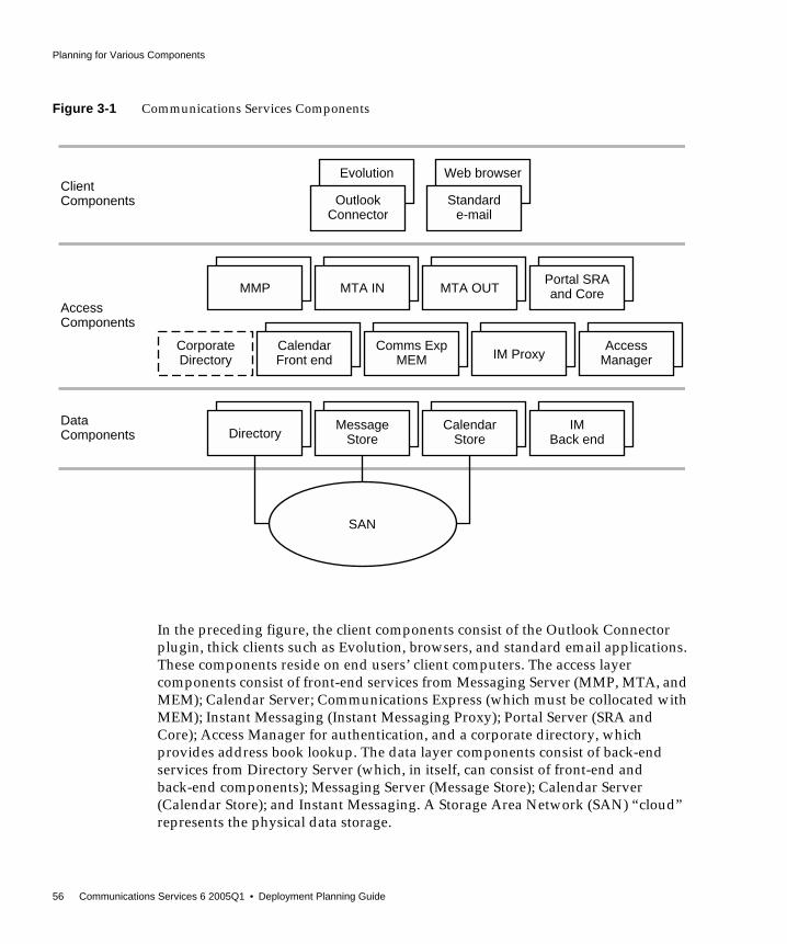
Planning for Various Components
56 Communications Services 6 2005Q1 • Deployment Planning Guide
Figure 3-1 Communications Services Components
In the preceding figure, the client components consist of the Outlook Connectorplugin, thick clients such as Evolution, browsers, and standard email applications.These components reside on end users’ client computers. The access layercomponents consist of front-end services from Messaging Server (MMP, MTA, andMEM); Calendar Server; Communications Express (which must be collocated withMEM); Instant Messaging (Instant Messaging Proxy); Portal Server (SRA andCore); Access Manager for authentication, and a corporate directory, whichprovides address book lookup. The data layer components consist of back-endservices from Directory Server (which, in itself, can consist of front-end andback-end components); Messaging Server (Message Store); Calendar Server(Calendar Store); and Instant Messaging. A Storage Area Network (SAN) “cloud”represents the physical data storage.
Evolution
MMP MTA IN MTA OUT
IM Proxy
OutlookConnector
Portal SRAand Core
DirectoryMessage
StoreCalendar
StoreIM
Back end
CorporateDirectory
CalendarFront end
Comms ExpMEM
AccessManager
Web browser
Standarde-mail
ClientComponents
DataComponents
AccessComponents
SAN

LDAP Directory Information Tree Requirements
Chapter 3 Understanding Product Requirements and Considerations 57
The following sections explain these various components in more detail.
LDAP Directory Information Tree RequirementsThe Directory Information Tree (DIT) is a way to organize directory entries in atree structure, or schema, with nodes representing domains, subdomains, users,and groups. Sun Java Enterprise System introduces a fundamental change to howthe directory is structured by implementing a one-tree structure.
Changes in the DIT StructureMessaging Server and Calendar Server have introduced a one-tree structure, wherethere is no Domain Component (DC) Tree. All domain information is held indomain nodes in the Organization Tree. Aliasing is handled entirely differently inthe new one-DIT structure.
The bottom half of Figure 3-2 illustrates a one-tree LDAP structure.
NOTE The corporate directory shown in this figure is not a componentproduct in itself. It represents a “copy” of the corporate directorythat enterprises typically deploy in the access layer for clients toperform address-book type lookups.
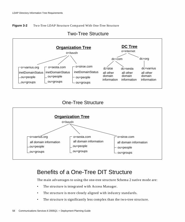
LDAP Directory Information Tree Requirements
58 Communications Services 6 2005Q1 • Deployment Planning Guide
Figure 3-2 Two-Tree LDAP Structure Compared With One-Tree Structure
Benefits of a One-Tree DIT StructureThe main advantages to using the one-tree structure Schema 2 native mode are:
• The structure is integrated with Access Manager.
• The structure is more closely aligned with industry standards.
• The structure is significantly less complex than the two-tree structure.
o=internet
dc=siroe dc=sesta
dc=org
o=varrius.org
ou=people
ou=groups
o=sesta.com
ou=people
ou=groups
DC TreeOrganization Treeo=basedn
dc=com
Two-Tree Structure
o=siroe.como=varrius.org
ou=people
ou=groups
ou=people
ou=groups
o=sesta.com
ou=people
ou=groups
Organization Treeo=basedn
One-Tree Structure
all domain informationall domain information all domain information
all other
information
dc=varriusinetDomainStatus inetDomainStatus
o=siroe.com
ou=people
ou=groups
inetDomainStatusdomain
all other
informationdomain
all other
informationdomain

LDAP Directory Information Tree Requirements
Chapter 3 Understanding Product Requirements and Considerations 59
As illustrated in the following figure, in the two-tree structure, some nodes pointdirectly to a node in the Organization Tree (using the attribute inetDomainBaseDN).Other nodes are aliased nodes, which instead of pointing directly to anOrganization Tree node, point to another DC Tree node, using thealiasedObjectName attribute.
Figure 3-3 Two-Tree Aliasing With aliasedDomainName and inetDomainBaseDN
In the previous figure, sesta.com in the DC Tree points to siroe.com in the DC Treeusing aliasedObjectName, and siroe.com points to the like named node in theOrganization Tree, using inetDomainBaseDN.
Furthermore, as shown in Figure 3-4 on page 60, there could be one or more nodesin the DC Tree using inetDomainBaseDN to point directly to the same node in theOrganization Tree. In this case, a “tie-breaker” attribute,inetCanonicalDomainName, is necessary on one of the DC Tree nodes to designatewhich is the “real” domain name (the domain where the mail actually resides andwhere the mail is routed).
o=internet
dc=siroe dc=sesta
dc=org
dc=varrius
o=siroe.como=varrius.org
ou=people
ou=groups
ou=people
ou=groups
DC TreeOrganization Treeo=basedn
dc=com

LDAP Directory Information Tree Requirements
60 Communications Services 6 2005Q1 • Deployment Planning Guide
Figure 3-4 Two-Tree Aliasing With inetCanonicalDomainName
By contrast, a one-tree structure contains only an Organization Tree, as shown inthe following figure.
Figure 3-5 One-Tree Aliasing With associatedDomain
In the one-tree structure, domain nodes in the Organization Tree contain all thedomain attributes formerly found on the DC Tree. Each domain node is identifiedby the sunManagedOrganization object class and sunPreferredDomain attribute,which contains the DNS domain name. A domain node can also have one or moreassociatedDomain attributes, which list the alias names this domain is known by.Contrary to the two-tree structure, there are no duplicate nodes for the alias names.
o=internet
dc=siroe dc=sesta
dc=org
dc=varrius
o=siroe.como=varrius.org
ou=people
ou=groups
ou=people
ou=groups
DC TreeOrganization Treeo=basedn
dc=com
inetCanonicalDomainName
Organization Tree
o=basedn|
o=sesta.comsunManagedOrganizationsunPreferredDomainassociatedDomain

Schema Requirements
Chapter 3 Understanding Product Requirements and Considerations 61
A one-tree DIT structure is beneficial in how you partition data fororganization-specific access control. That is, each organization can have a separatesubtree in the DIT where user and group entries are located. Access to that data canbe limited to users in that part of the subtree. This allows localized applications tooperate securely.
In addition, for new deployments of Calendar Server or Messaging Server, aone-tree structure maps better to existing single-DIT LDAP applications.
Schema RequirementsBefore you install any of the Communications Services products, you need tounderstand which schema you will use. The schema is the set of definitionsdescribing what types of information can be stored as entries in the directory. Twoschema choices, Sun Java™ System LDAP Schema 1 and Sun Java™ System LDAPSchema 2, are available and supported with Communications Services. Your choiceof schema depends on the following criteria:
Use Schema 2 if you:
• Want to use Access Manager 6 2005Q1 (formerly Identity Server), either foruser provisioning or single sign-on (SSO)
• Are installing Communications Services components for the first time
• Are integrating Communications Services with other Java Enterprise Systemproducts, such as Portal Server
Use Schema 1 if you:
• Have an existing version of any of the Communications Services components,for example, if you are upgrading from Messaging Server 5.2
• Do not need to provision users through Access Manager (unless AccessManager SSO is also a requirement)
• Want to use Sun ONE Delegated Administrator (formerly called iPlanet™Delegated Administrator) to do your user provisioning
NOTE You do not have to use Access Manager 6 to provide SSO. If youchoose, you can still use the trusted circle type of SSO, which doesnot rely on Access Manager 6.

Directory Server Considerations
62 Communications Services 6 2005Q1 • Deployment Planning Guide
See Chapter 8, “Understanding Schema and Provisioning Options” for moreinformation on schema choices.
Directory Server ConsiderationsSun Java System Directory Server provides flexible, multi-tiered data storage forintranet, network, and extranet information. Directory Server integrates withexisting systems and acts as a centralized repository for the consolidation ofemployee, customer, supplier, and partner information. You can extend DirectoryServer to manage user profiles and preferences, as well as extranet userauthentication.
All custom LDAP schemas, such as those from Portal Server, Access Manager,Messaging Server, Calendar Server, and Instant Messaging Server, install into asingle Directory.
There are many ways to architect your data environment and many factors toconsider that depend on your business objective and expected usage patterns. Yourdirectory design should address the following areas:
• Directory schema and object class definitions
• The Directory Information Tree (DIT)
• Groups and membership definitions
• A strategy for Access Control Lists (ACLs) including static and dynamicgroups
• Directory architecture for high availability and performance, includingfailover, replication, and referrals
• Management of the directory
See the Sun Java System Directory Server Deployment Planning Guide for a completedescription of these factors and suggestions about how to architect your dataenvironment:
http://docs.sun.com/doc/817-7607
Directory Server Considerations
Chapter 3 Understanding Product Requirements and Considerations 63
Directory Server and Tiered ArchitectureConsiderationsIn moving from a single-tiered architecture to a multiple-tiered architecture,Directory Server should be the first component that you “split out” onto its ownmachine. At a certain point of load, Directory Server and Messaging Server on thesame host have inherent performance impacts. This is due to the way MessagingServer is architected to work with Directory Server. Separating Directory Serveronto its own machine is the first step to improve performance for a deployment.
See Chapter 5, “Developing a Communications Services Logical Architecture” formore information on tiered architectures.
Directory Server Topology ConsiderationsThough it is feasible to build a deployment around an instance of Directory Serverinstalled on a single machine, the other Communications Services componentsdepend upon the directory as a core service to function. Thus, beyond trivialdeployments, you should plan to deploy Directory Server in a redundant or highlyavailability configuration.
The first step toward making Directory Server more available is to establish a pairof master directory servers. Next, multimaster replication can be used to improvethe LDAP write throughput and availability. If Sun Cluster is used for ahigh-availability deployment, then the two LDAP masters are clustered together.See “Directory Server and High Availability” on page 99 for more information.
NOTE You can install Directory Server in such a way to have a clearseparation between the directory user management and thesoftware application configuration. In this architecture, there aretwo directories: a user/group directory on a directory host, and aconfiguration directory on a separate host. Should you want toremove the software application configuration piece, this separationprovides a cleaner way of removing that information from DirectoryServer.

Directory Server Considerations
64 Communications Services 6 2005Q1 • Deployment Planning Guide
Directory Server Capacity PlanningWhile there are no hard and fast rules for Directory Server capacity planning,actively monitoring the directory is essential to ensure that performance metricsare met. When the system is not meeting these metrics, then it is time to add anadditional directory consumer. Typically, you will want to monitor:
• Hit load
• Cache load
• Requests per second
Evaluate the above metrics against a target response time of 10 Milliseconds. TheIOWAIT should not exceed 10 Milliseconds, and the sum of the CPU utilization inthis tier should not exceed 70 percent.
Directory Server and Calendar ServerInteraction ConsiderationsCalendar Server performs multiple writes to user entries stored in DirectoryServer. The bulk of these writes occur when the user logs into Calendar Server forthe first time and when the user performs certain actions. These actions includecreating a calendar, subscribing to a calendar, changing a preference, and so on. Ifyou do not take these actions into consideration, the Directory Master Server canexperience heavy loads.
If you use Directory replication, the LDAP Master Server is replicating entries tothe LDAP Replica servers. As Calendar users perform one of these actions,Calendar Server will only be able to write changes to the Master Directory Server.This is because the Replicas are read-only.
A second interaction consideration exists in these replicated Directory structures.As users make preference changes, their changes might not be rendered successfuluntil the change is successfully replicated from the Master Directory Server to theDirectory Replica, which is in use by the Calendar Server. A workaround isavailable, in which you configure Calendar Express (cshttpd) attempts to cache thechange locally to avoid this latency delay. See “Planning for the Calendar ServerLDAP Data Cache” on page 268 for more information.

Messaging Server Considerations
Chapter 3 Understanding Product Requirements and Considerations 65
Directory Server and Personal Address BookConsiderationsThe Messenger Express Client supports the concept of a Personal Address Book(PAB). This enables users to store personal contacts (for example, businesscontacts, friends, and family) in the Directory Server. Each time a new personalcontact is added to the user’s PAB, a write is made on the Directory Server. If youdo not take these actions into consideration, the LDAP Master Server can faceheavy loads (regardless of the Directory replication strategy).
One method to avoid performance issues on the User and Group Directory Serveris to place the PAB information on a separate Directory Server. This enables PABinteractions to avoid placing a load on the LDAP Master Server.
Messaging Server ConsiderationsIn developing your Communications Services architecture, you need to evaluatethe performance aspects of the following Messaging Server components:
• Message Store
• Message Transfer Agent (MTA)
• Mail Message Proxy (MMP)
• Messaging Express Multiplexor (MEM)
For a complete discussion of the performance aspects of these components, andpotential hardware solutions, see “Performance Considerations for a MessagingServer Architecture” on page 179.
NOTE If you are running both the current Communications Express clientand also the deprecated Messenger Express Web mail interface, theaddress books used by these two clients do not share information. Ifend users switch between the two client interfaces, the two addressbooks will contain different entries.

Calendar Server Considerations
66 Communications Services 6 2005Q1 • Deployment Planning Guide
Calendar Server ConsiderationsCalendar Server consists of five major services:
• HTTP Service (cshttpd) listens for HTTP requests. It receives user requests andreturns data to the caller.
• Administration Service (csadmind) is required for each instance of CalendarServer. It provides a single point of authentication and administration for theCalendar Servers and provides most of the administration tools.
• Notification Service (csnotify) sends notifications of events and to-dos usingeither email or the Event Notification Service.
• Event Notification Service (enpd) acts as the broker for event and alarmnotifications.
• Distributed Database Service (csdwpd) links multiple database servers togetherwithin the same Calendar Server system to form a distributed calendar store.
• Backup Service (csstored) implements automatic backups, both archivalbackups and hot backups. The first backup is a snapshot with log files, thesecond is a snapshot with log files applied. This service is automatically startedwhen you run the start-cal command. However, it is not enabled atinstallation time, so you must configure it to function. If left unconfigured,Backup Service sends out a message to the administrator every 24 hours, withthe notification that the service is not configured.
In a scalable Calendar Server deployment, you would deploy front-end systems inconjunction with a back-end server. The front-end systems would contain oneinstance of the cshttpd daemon per processor and a single Administration Service.A back-end server would contain an instance of Notification Service, EventNotification Service, Distributed Database Service and Administration Service.
Authentication and XML / XSLT transformation are two Calendar Serviceactivities that generate heavy load. Additional CPUs can be added to meet qualityof service requirements. In a scalable environment, these heavy load activities takeplace on the front-end system(s), permitting more CPUs to be added to individualfront-end systems, or more front-end systems to be added, to meet quality ofservice requirements.
Calendar Server Considerations
Chapter 3 Understanding Product Requirements and Considerations 67
Calendar back-end services usually require half the number of CPUs sized for theCalendar front-end services. To support quality of service by the Calendarfront-end system, the Calendar back-end system should use around two-thirds ofthe front-end CPUs.
Consider early on in your deployment planning to separate the Calendar Serviceinto front-end and back-end services.
The Calendar Server HTTP process that is typically a component of the front-endservices is a dominant user of CPU time. Thus, account for peak calendar usageand choose sufficient front-end processing power to accommodate the expectedpeak HTTP sessions. Typically, you would make the Calendar Server front endmore available through redundancy, that is, by deploying multiple front-end hosts.As the front-end systems do not maintain any persistent calendar data, they are notgood candidates for HA solutions like Sun Cluster or Veritas. Moreover, theadditional hardware and administrative overhead of such solutions makedeploying HA for Calendar Server front ends both expensive and time-consuming.
A good choice of hardware for the Calendar Server front ends is a single or dualprocessor server. You would deploy one instance of the Calendar Server cshttpdprocess per processor. Such a deployment affords a cost-effective solution,enabling you to start with some level of initial client concurrency capability andadd client session capacity as you discover peak usage levels on your existingconfiguration.
When you deploy multiple front ends, a load balancer (with sticky/persistentconnections) is necessary to distribute the load across the front-end services.
NOTE The preceding paragraph is not applicable if the CommunicationsExpress Calendar client is used for calendar access.Communications Express uses the WCAP protocol to accessCalendar Server data and therefore the Calendar Serverinfrastructure is not doing the XML/XSLT translations. See Part V,“Deploying Communications Express” for information ondeploying Communications Express.
NOTE The only configuration for Calendar front ends that might warrant atrue HA solution is where you have deployed the Calendar frontend on the same host that contains a Messaging Server MTA router.Even in this configuration, however, the overhead of such a solutionshould be carefully weighed against the slight benefit.

Instant Messaging Considerations
68 Communications Services 6 2005Q1 • Deployment Planning Guide
The Calendar Server back-end services are well balanced in resource consumptionand show no evidence of bottleneck formation either in CPU or I/O (disk ornetwork). Thus, a good choice of hardware for the back end would be a SPARCserver with a single striped volume. Such a machine presents considerable capacityfor large-peak calendar loads.
If your requirements include high availability, it makes sense to deploy theCalendar Server back end with Sun Cluster, as the back end does contain persistentdata.
Instant Messaging ConsiderationsAs with other Communications Services components, you can create anarchitecture in which you separate Instant Messaging into front-end (InstantMessaging multiplexor) and back-end components (server and store). See“Developing Instant Messaging Architectural Strategies” on page 305 for moreinformation.
NOTE Communications Express does not scale beyond two processors.The same hardware choices explained previously for CalendarServer apply to Communications Express deployments.
NOTE In a configuration with both front-end and back-end CalenderServer hosts, all hosts must be running:
• The same operating system
• The same releases of Calendar Server, including patch or hotfixreleases
Portal Server Considerations
Chapter 3 Understanding Product Requirements and Considerations 69
Portal Server ConsiderationsYou can install Communications Services products with Portal Server to providean “umbrella” front end to access messaging, calendar, and instant messagingapplications. The integration of Portal Server includes single sign-on capabilitiesbetween Portal Server, Calendar Express web client, Messaging Express web clientand Communications Express client. In addition, the Messaging Express, CalendarExpress, and Instant Messaging clients are made available to users through thePortal Server desktop.
See the Sun Java System Portal Server Deployment Guide and the Sun Java SystemAccess Manager Deployment Planning Guide for more information:
http://docs.sun.com/doc/817-6257
http://docs.sun.com/doc/817-7644
Connector for Microsoft Outlook ConsiderationsThis section describes some deployment issues you will encounter deployingConnector for Microsoft Outlook. For complete information, see the Connector forMicrosoft Outlook documentation:
http://docs.sun.com/db/coll/MessagingServer_05q1
Sun Java System Connector for Microsoft Outlook enables Outlook to be used as adesktop client with Sun Java Enterprise System. Connector for Microsoft Outlookis an Outlook plug-in that must be installed on the end-user’s desktop. Connectorfor Microsoft Outlook queries Messaging Server for folder hierarchies and emailmessages. It converts the information into Messaging API (MAPI) properties thatOutlook can display. Similarly, it uses the WCAP protocol to query CalendarServer for events and tasks which are then converted into MAPI properties. Withthis model, Connector for Microsoft Outlook builds an end-user Outlook viewfrom two separate information sources: mail from Messaging Server and calendarinformation from Calendar Server.
When users create and modify items through Outlook, Connector for MicrosoftOutlook passes the new message along to the appropriate server depending on itsmessage type. It sends new outgoing email to an SMTP mail server for delivery,and sends modified email messages back to the user’s IMAP folder for storage.New calendar events and tasks are converted into a standard format to be stored inthe Calendar Server database.
Connector for Microsoft Outlook Considerations
70 Communications Services 6 2005Q1 • Deployment Planning Guide
Connector for Microsoft Outlook ComponentProduct DependenciesTo use Connector for Microsoft Outlook, both Messaging Server and CalendarServer are required in the same deployment. See those products’ release notes forinformation on supported versions.
For Connector for Microsoft Outlook to function correctly, the following LDAPattributes in the Sun Java System Directory Server should be indexed for at leastpresence and equality to improve the overall performance:
• icsCalendar
• mailalternateaddress
See the Sun Java System Connector for Microsoft Outlook Release Notes for a completelist of product dependencies.
http://docs.sun.com/db/coll/MessagingServer_05q1
Migrating Sun ONE Calendar Server DataIf you are using a version of Calendar Server prior to Sun ONE Calendar Server 6.0,you need to engage Sun Client Services to convert and migrate the data to the newformat. This Calendar Server data migration is required for the use of Outlook, andis necessary because of the underlying changes in the storage and management ofrecurring events. No migration service is required for new customers of Sun JavaSystem Calendar Server.
Migrating Exchange Server DataConnector for Microsoft Outlook does not convert Microsoft Exchange Servermessages on the Exchange Server. You need to engage with Sun Client Services toconvert the data.

Communications Express Considerations
Chapter 3 Understanding Product Requirements and Considerations 71
Communications Express ConsiderationsSun Java System Communications Express provides an integrated web-basedcommunications and collaboration client. Communications Express is a commonpart of Messaging Server and Calendar Server, providing end users with a webinterface to their calendar information and mail, as well as an address book.
Communications Express consists of three client modules: Calendar, AddressBook, and Mail. The Calendar and Address Book client modules are deployed as asingle application on a web container. Messenger Express is the standaloneweb-based mail application that uses the HTTP service of the Messaging Server.Messenger Express should be deployed on the same system as CommunicationsExpress.
Communications Express depends upon the following Sun Java Systemcomponent products:
• Directory Server
• Access Manager (If you are using Sun Java System LDAP Schema Version 2)
• Calendar Server
• Messaging Server
• Web Server/Application Server (for web container)
S/MIME ConsiderationsCommunications Express Mail includes the security advantages of theSecure/Multipurpose Internet Mail Extension (S/MIME). CommunicationsExpress Mail users who are set up to use S/MIME can exchange signed orencrypted messages with other Communications Express Mail users, and withusers of the Microsoft Outlook mail system.
See “Requirements for Using S/MIME with Communications Express Mail” onpage 350 for more information.

Communications Express Considerations
72 Communications Services 6 2005Q1 • Deployment Planning Guide

73
Chapter 4
Determining Your NetworkInfrastructure Needs
Your network infrastructure is the underlying foundation of the system. It formsthe services that create the operating makeup of your network. In aCommunications Services deployment, determining your network infrastructurefrom the project goals ensures that you will have an architecture that can scale andgrow.
This chapter contains the following sections:
• Understanding Your Existing Network
• Understanding Network Infrastructure Components
• Planning Your Network Infrastructure Layout
Understanding Your Existing NetworkYou need to understand your existing network infrastructure to determine howwell it can meet the needs of your deployment goals. By examining your existinginfrastructure, you identify if you need to upgrade existing network componentsor purchase new network components. You should build up a complete map of theexisting network by covering these areas:
1. Physical communication links, such as cable length, grade, and so forth
2. Communication links, such as analog, ISDN, VPN, T3, and so forth, andavailable bandwidth and latency between sites
3. Server information, including:
❍ Host names
Understanding Network Infrastructure Components
74 Communications Services 6 2005Q1 • Deployment Planning Guide
❍ IP addresses
❍ Domain Name System (DNS) server for domain membership
4. Locations of devices on your network, including:
❍ Hubs
❍ Switches
❍ Modems
❍ Routers and bridges
❍ Proxy servers
5. Number of users at each site, including mobile users
After completing this inventory, you need to review that information inconjunction with your project goals to determine what changes are required so thatyou can successfully deliver the deployment.
Understanding Network InfrastructureComponents
The following common network infrastructure components have a direct impactupon the success of your deployment:
• Routers and switches
• Firewalls
• Load balancers
• Storage Area Network (SAN)
• DNS
Routers and SwitchesRouters connect networks of your infrastructure, enabling systems tocommunicate. You need to ensure that the routers have spare capacity after thedeployment to cope with projected growth and usage.
In a similar vein, switches connect systems within a network.

Understanding Network Infrastructure Components
Chapter 4 Determining Your Network Infrastructure Needs 75
Routers or switches running at capacity tend to induce escalating bottlenecks,which result in significantly longer times for clients to submit messages to serverson different networks. In such cases, the lack of foresight or expenditure toupgrade the router or switch could have a personnel productivity impact fargreater than the cost.
FirewallsFirewalls sit between a router and application servers to provide access control.Firewalls were originally used to protect a trusted network (yours) from theuntrusted network (the Internet). These days, it is becoming more common toprotect application servers on their own (trusted, isolated) network from theuntrusted networks (your network and the Internet).
Router configurations add to the collective firewall capability by screening the datapresented to the firewall. Router configurations can potentially block undesiredservices (such as NFS, NIS, and so forth) and use packet-level filtering to blocktraffic from untrusted hosts or networks.
In addition, when installing a Sun server in an environment that is exposed to theInternet, or any untrusted network, reduce the Solaris software installation to theminimum number of packages necessary to support the applications to be hosted.Achieving minimization in services, libraries, and applications helps increasesecurity by reducing the number of subsystems that must be maintained. TheSolaris™ Security Toolkit provides a flexible and extensible mechanism tominimize, harden, and secure Solaris systems.
Your Site Security Policy should provide direction on such issues.
Load BalancersUse load balancers to distribute overall load on your Web or application servers, orto distribute demand according to the kind of task to be performed. If, for example,you have a variety of dedicated applications and hence different applicationservers, you might use load balancers according to the kind of application the userrequests.
If you have multiple data centers, you should consider geographic load balancing.Geographic load balancing distributes load according to demand, site capacity,and closest location to the user. If one center should go down, the geographic loadbalancer provides failover ability.

Understanding Network Infrastructure Components
76 Communications Services 6 2005Q1 • Deployment Planning Guide
For load balancers on Web farms, place the hardware load balancers in front of theservers and behind routers because they direct routed traffic to appropriateservers. Software load balancing solutions reside on the Web servers themselves.With software solutions, one of the servers typically acts a traffic scheduler.
A load balancing solution is able to read headers and contents of incoming packets.This enables you to balance load by the kind of information within the packet,including the user and the type of request. A load balancing solution that readspacket headers enables you to identify privileged users and to direct requests toservers handling specific tasks.
You need to investigate how dynamically the load balancer communicates with allthe servers it caters to. Does the scheduler ping each server or create “live” agentsthat reside on the servers to ascertain load data? You should also examine how theload balancer parses TCP packets. Pay attention to how quickly the load balancercan process a packet. Some load balancers will be more efficient than others. Loadbalancer efficiency is typically measured in throughput.
Storage Area Networks (SANs)Understanding the data requirements of the storage system is necessary for asuccessful deployment. Increasingly, SANs are being deployed so that the storageis independent of the servers used in conjunction with it. Deploying SANs canrepresent a decrease in the time to recover from a non-functional server as themachine can be replaced without having to relocate the storage drives.
Use these questions to evaluate if your deployment storage requirements would bebest served through a SAN:
• Are reads or writes more prevalent?
• Do you need high I/O rate storage? Is striping the best option?
• Do you need high uptime? Is mirroring the best option?
• How is the data to be backed up? When is it going to be backed up?
Domain Name System (DNS)Servers which make heavy usage of DNS queries should be equipped with a localcaching DNS server to reduce lookup latency as well as network traffic.

Planning Your Network Infrastructure Layout
Chapter 4 Determining Your Network Infrastructure Needs 77
When determining your requirements, consider allocating host names forfunctions such as mailstore, mail-relay-in, mail-relay-out, and so forth. You shouldconsider this policy even if the host names all are currently hosted on one machine.With services configured in such a way, relocation of the services to alternatehardware significantly reduces the impacts of the change.
Planning Your Network Infrastructure LayoutIn deriving your infrastructure topology, you need to consider the followingtopics:
• DMZ
• Intranet
• Internal network
• Proxies
• Firewall Configuration
• Mobile users
Demilitarized Zone (DMZ)These days, most company networks are configured for a DMZ. The DMZseparates the corporate network from the Internet. The DMZ is a tightly securedarea into which you place servers providing Internet services and facilities (forexample, web servers). These machines are hardened to withstand the attacks theymight face. To limit exposure in case of a security breach from such attacks, theseservers typically contain no information about the internal network. For example,the nameserver facilities only include the server and the routers to the Internet.
Progressively, DMZ implementations have moved the segment behind the firewallas firewall security and facilities have increased in robustness. However, the DMZstill remains segmented from the internal networks. You should continue to locateall machines hosting Web servers, FTP servers, mail servers, and external DNS on aDMZ segment.
A simpler network design might only define separate DMZ segments for Internetservices, VPN access, and remote access. However, security issues exist with VPNand remote access traffic. You need to separate appropriate connections of thesetypes from the rest of the network.

Planning Your Network Infrastructure Layout
78 Communications Services 6 2005Q1 • Deployment Planning Guide
The firewall providing the DMZ segmentation should allow only inbound packetsdestined to the corresponding service ports and hosts offering the services withinthe DMZ. Also, limit outbound initiated traffic to the Internet to those machinesrequiring access to the Internet to carry out the service they are providing (forexample, DNS and mail). You might want to segment an inbound-only DMZ andan outbound-only DMZ, with respect to the type of connection requests. However,given the potential of a denial-of-service attack interrupting DNS or email,consider creating separate inbound and outbound servers to provide theseservices. Should an email-based Trojan horse or worm get out of control andoverrun your outbound mail server, inbound email can still be received. Apply thesame approach to DNS servers.
IntranetThe DMZ provides a network segment for hosts that offer services to the Internet.This design protects your internal hosts, as they do not reside on the same segmentas hosts that could be compromised by an external attack. Internally, you also havesimilar services to offer (Web, mail, file serving, internal DNS, and so on) that aremeant solely for internal users. Just as the Internet services are segmented, so too,are the internal services. Separation of services in this manner also permits tightercontrols to be placed on the router filtering.
Just as you separate the Internet-facing services into the DMZ for security, yourprivate internal services should reside in their own internal DMZ. In addition, justas multiple DMZs can be beneficial—depending on your services and yournetwork’s size—multiple intranets might also be helpful.
The firewall rules providing the segmentation should be configured similarly tothe rules used for the DMZ’s firewall. Inbound traffic should come solely frommachines relaying information from the DMZ (such as inbound email being passedto internal mail servers) and machines residing on the internal network.
Internal NetworkThe segments that remain make up your internal network segments. Thesesegments house users’ machines or departmental workstations. These machinesrequest information from hosts residing on the intranet. Development, lab, and testnetwork segments are also included in this list. Use a firewall between eachinternal network segment to filter traffic to provide additional security betweendepartments. Identify the type of internal network traffic and services used on eachof these segments to determine if an internal firewall would be beneficial.

Planning Your Network Infrastructure Layout
Chapter 4 Determining Your Network Infrastructure Needs 79
Machines on internal networks should not communicate directly with machines onthe Internet. Preferably, these machines avoid direct communication withmachines in the DMZ. Ultimately, the services they require should reside on hostsin the intranet. A host on the intranet can in turn communicate with a host in theDMZ to complete a service (such as outbound email or DNS). This indirectcommunication is acceptable.
ProxiesOnly the machines directly communicating with machines on the Internet shouldreside in the DMZ. If users require Internet access, though, this creates a problembased on your previous topology decisions. In this situation, proxies becomehelpful. Place a proxy on an internal network segment, or, better yet, an intranetsegment. A machine requiring access to the Internet can pass its request onto theproxy, which in turn makes the request on the machine’s behalf. This relay out tothe Internet helps shield the machine from any potential danger it might encounter.
Because the proxy communicates directly with machines on the Internet, it shouldreside in the DMZ. However, this conflicts with the desire to prevent internalmachines from directly communicating with DMZ machines. To keep thiscommunication indirect, use a double proxy system. A second proxy residing inthe intranet passes connection requests of the internal machines to the proxy in theDMZ, which in turn makes the actual connection out on the Internet.
Firewall ConfigurationIn addition to the typical packet-filtering features, most firewalls provide featuresto prevent IP spoofing. Use IP-spoofing protection whenever possible.
For instance, if there is only one entry point into your network from the Internetand a packet is received from the Internet with a source address of one of yourinternal machines, it was likely spoofed. Based on your network’s topology, theonly packets containing a source IP address from your internal machines shouldcome from within the network itself, not from the Internet. By preventing IPspoofing, this possibility is eliminated, and the potential for bypassing IPaddress-based authorization and the other firewall-filtering rules is reduced. Usethe same IP-spoofing protection on any internal firewall as well.

Planning Your Network Infrastructure Layout
80 Communications Services 6 2005Q1 • Deployment Planning Guide
Mobile UsersWhen you have remote or mobile users, pay attention to how you will providethem access to the facilities. Will there be any facilities they cannot access? Whatkind of security policies do you need to address? Will you require SSL forauthentication? Also, examine whether your mobile user population is stable or isexpected to increase over time.
81
Chapter 5
Developing a CommunicationsServices Logical Architecture
This chapter describes how to develop your Communications Services logicalarchitecture. The logical architecture is a design that depicts the logical buildingblocks of the Communications Services components and the infrastructure servicesneeded to support them.
This chapter contains the following sections:
• Communications Services Deployment Logical Architectures Overview
• Horizontal Scalability Strategy
• Other Deployment Issues
Communications Services Deployment LogicalArchitectures Overview
You can deploy Communications Services in either a single-tiered or two-tieredlogical architecture. Deciding on your logical architecture is crucial, as itdetermines which machine types you will need, as well as how many.
In general, enterprise corporate deployments use a single-tiered architecture whileinternet service providers (ISPs) and telecommunications deployments use atwo-tiered architecture. However, as with all generalities, the exceptions prove therule. Small ISPs might just as well deploy on a single machine, and larger,centralized enterprises might deploy in a two-tiered architecture for many of thesame reasons that ISPs do. As more and more corporations look to offer ease ofaccess to employees working remotely, their deployments will begin to look moreand more like an ISP.

Communications Services Deployment Logical Architectures Overview
82 Communications Services 6 2005Q1 • Deployment Planning Guide
This section discuss the following Communications Services logical architectures:
• Single-tiered Architecture. All services are either located on a single hostsufficiently provisioned with memory and CPUs, or deployed on multipleservers, with each server hosting all of a particular component product’sservices.
• Two-tiered Architecture. The access and data layers for the componentproducts are separated onto different servers.
• Edge Architecture. Builds on the two-tiered architecture by also providing forsecure connections over the Internet to a mobile workforce.
Whether you deploy Communications Services in a single-tiered or multiple-tieredarchitecture, you need to understand the advantages and disadvantages of bothmodels.
Single-tiered Logical Architecture for One HostAs its name implies, the single-tiered logical architecture for one host locates allservices onto a single machine. In general, such an architecture is best suited forenterprises that are:
• Composed of 500 users or less
• Not geographically distributed
• Served by few administrators
• Seeking an entry-level configuration
The following figure represents the single-tiered logical architecture for one host.
Figure 5-1 Single-tiered Architecture for One Host
Clients(POP, IMAP, Web)
Tier 1
User Tier
CalendarServer
MessagingServer
InstantMessaging
DirectoryServer
Web Server/Application
Server
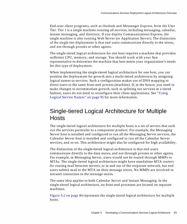
Communications Services Deployment Logical Architectures Overview
Chapter 5 Developing a Communications Services Logical Architecture 83
End-user client programs, such as Outlook and Messenger Express, form the UserTier. Tier 1 is a single machine running all services, including messaging, calendar,instant messaging, and directory. If you deploy Communications Express, thesingle machine is also running Web Server (or Application Server). The distinctionof the single tier deployment is that end users communicate directly to the stores,and not through proxies or other agents.
The single-tiered logical architecture for one host requires a machine that providessufficient CPU, memory, and storage. You should work with your Sunrepresentative to determine the machine that best meets your organization’s needsfor this type of deployment.
When implementing the single-tiered logical architecture for one host, you canposition the deployment for growth into a multi-tiered architecture by assigninglogical names to services. Such a configuration makes use of DNS mapping todirect users to the same front-end process (machine). If, in the future, you need tomake changes to accommodate growth, such as splitting out services in a tieredfashion, users do not need to reconfigure their client applications. See “UsingLogical Service Names” on page 95 for more information.
Single-tiered Logical Architecture for MultipleHostsThe single-tiered logical architecture for multiple hosts is a set of servers that eachrun the services particular to a component product. For example, the MessagingServer host is installed and configured to run all the Messaging Server services, theCalendar Server host is installed and configured to run all the Calendar Serverservices, and so on. This architecture might also be configured for high availability.
The distinction of the single-tiered logical architecture is that end userscommunicate directly to the data stores, and not through proxies or other agents.For example, in Messaging Server, users would not be routed through MMPs orMTAs. The single-tiered logical architecture might have standalone MTA routersfor routing mail between servers, or in and out of the corporate network, but endusers submit mail to the MTA on their message stores. No MMPs are involved inintranet connection to the message stores.
The same idea applies to both Calendar Server and Instant Messaging. In thesingle-tiered logical architecture, no front-end processes are located on separatemachines.
Figure 5-2 on page 84 represents the single-tiered logical architecture for multiplehosts.

Communications Services Deployment Logical Architectures Overview
84 Communications Services 6 2005Q1 • Deployment Planning Guide
Figure 5-2 Single-tiered Architecture for Multiple Hosts
In the preceding figure, end-user client programs, such as Outlook and MessengerExpress, form the User Tier. Tier 1 is a set of four servers. One server runs theCalendar Server processes, the second runs the Messaging Server processes, thethird runs the Instant Messaging processes, and the fourth runs the DirectoryServer process. If you are deploying Communications Express, the MessagingServer host also includes a web server, either Web Server or Application Server,(for Webmail).
Single-tiered Distributed Logical ArchitectureThe single-tiered distributed logical architecture is a variant of the single-tieredarchitecture in that the Directory Server is deployed in two tiers. Such adeployment works well for enterprises with small departments or organizationsthat are geographically distributed. Each department or office has its own services(mail, calendar, instant messaging) and a local directory instance (consumer). Allthe local directory instances are cached, but are synchronized with the centralized,master corporate repository. This is a fairly common scenario for offices with lowbandwidth connectivity. The directory is architected in a two-tiered fashion andreplicated over the low-bandwidth to keep data local.
Figure 5-3 on page 85 represents the single-tiered distributed logical architecture.
Clients(POP, IMAP, Web)
Tier 1
User Tier
CalendarServer
ApplicationServer/
Web Server/Messaging
Server
InstantMessaging
DirectoryServer

Communications Services Deployment Logical Architectures Overview
Chapter 5 Developing a Communications Services Logical Architecture 85
Figure 5-3 Single-tiered Distributed Architecture
In the preceding figure, end-user client programs, such as Outlook and MessengerExpress, form the User Tier. Tier 0 consists of load balancers that distribute loadacross the Tier 1 layer. Tier 1 is a set of multiple servers for the CommunicationsServices processes. Multiple servers run the Calendar Server processes, multipleservers run the Messaging Server processes, and multiple servers run the InstantMessaging processes. Directory Server processes are split between a consumerserver in Tier 1 running a local, replicated copy of the directory, and another serversituated in Tier 2, which contains the master copy of the directory. Notice that inthis kind of deployment, client queries are directed to the local directory copy, notto the master copy. Only the local Directory Server communicates to the masterDirectory Server.
Load BalancingSoftware/Switches
Clients(POP, IMAP, Web)
Tier 1
Tier 2
Tier 0
User Tier
CalendarServer
MessagingServer
InstantMessaging
DirectoryServer
(Local Copy)
DirectoryServer
Infrastructure

Communications Services Deployment Logical Architectures Overview
86 Communications Services 6 2005Q1 • Deployment Planning Guide
Two-tiered Logical ArchitectureIn a two-tiered logical architecture, the data stores communicate through front-endprocesses. In the case of Messaging Server, this means MMPs, MEMs, and MTAsare residing on separate machines from the data store processes. A two-tieredarchitecture enables the mail store to offload important and common tasks andfocus on receiving and delivering mail. In the case of Calendar Server, this meansthe HTTP service and Administration service reside on a separate machine fromthe store processes. In the case of Instant Messaging, this means the proxy service isresiding on a separate machine from the back-end processes.
There might be some level of cohabitation with other services. For example, youcould have the Calendar store and the Message Store on the same machine.Similarly, you could have the calendar front end on the MMP machine.
In a two-tiered logical architecture, Directory Server is usually a complexdeployment in its own right, with multi-master and replication to a set ofload-balanced consumer directories.
Figure 5-4 on page 87 represents the two-tiered logical architecture.
NOTE When deploying a single-tiered architecture with Internetconnectivity, use a separate access layer. For example, you directaccess to the data stores from inside the intranet without having touse SSL. However, you direct access to the data stores from theInternet through an access layer over SSL. This offloads much of theSSL load on the data stores to the access layer that separates it fromthe Internet.
The downside to this type of deployment is that users who make useof the server from a system that is sometimes on the corporateintranet and sometimes accessing the server from the Internet mustconfigure their client applications to use SSL all the time. This isbecause it is too much trouble to switch back and forth. Therefore,there will still be a substantial percentage of SSL traffic being put onthe stores directly. By using an access layer inside the intranet, youcan remove that problem and by limiting connection directionsfurther protect the intranet from illegal access.

Communications Services Deployment Logical Architectures Overview
Chapter 5 Developing a Communications Services Logical Architecture 87
Figure 5-4 Two-tiered Architecture
In the preceding figure, end-user client programs, such as Outlook and MessengerExpress, form the User Tier. The load balancers form Tier 0. The Calendar Server,Messaging Server, Instant Messaging, and web proxy and MEM front ends formTier 1. Finally, the Directory Server, Calendar Server, Messaging Server, andInstant Messaging back ends form Tier 2. When deploying CommunicationsExpress, you could have Web Server in Tier 2 as well.
A two-tiered architecture enables you to deploy Tier 1 and Tier 2 elements asseparate instances, increasing overall flexibility of design. Additionally, youenhance system security by assigning discrete functions to individual instances.
For typical deployments, place the messaging and calendar front ends within thenetwork Demilitarized Zone (DMZ), connecting to the main messaging andcalendar services through a firewall. This configuration enables you to scale thesystem horizontally, as the Tier 1 elements can be scaled independently. Do notscale these elements beyond the capacity of the back-end servers.
Tier 2
DirectoryServer
CalendarServer
Back ends
MessagingServer
Back ends
InstantMessagingBack ends
WebServer
Load BalancingSoftware/Switches
Clients(Outlook, Web)
Tier 1
Tier 0
User Tier
CalendarServer
Front ends
MessagingServerMMPs
Web Proxies/Messaging
Server MEMs
InstantMessaging
Proxies

Communications Services Deployment Logical Architectures Overview
88 Communications Services 6 2005Q1 • Deployment Planning Guide
When the front-end elements have reached the capacity of the back-end servers,you can scale the back-end Tier 2 elements to support more users. In general, thefront end should scale as a function of the traffic. The back end should be scaled asa function of the number of users.
Edge Logical ArchitectureThe edge logical architecture adds security for remote access to the two-tieredlogical architecture. An edge deployment grants access to a remote, mobileworkforce over the public Internet by using only name/password authentication(SMTPAuth). As messages travel to and from the corporate network over the publicInternet, they are encrypted through the use of SSL. No virtual private network isinvolved. The internal side of the communications transmission is “in the clear” formaximum performance. Access is contained on the “edge” of the deployment,protecting the data stores from unauthorized intrusion.
Business reasons for an edge deployment include:
• Your workforce consists of mobile, remote workers.
• You do not want to install and maintain Communications Services servers atevery remote site.
Figure 5-5 on page 89 represents the edge logical architecture.
NOTE For specific instructions on sizing components in single-tiered ortwo-tiered architectures, contact your Client Services representative.

Communications Services Deployment Logical Architectures Overview
Chapter 5 Developing a Communications Services Logical Architecture 89
Figure 5-5 Edge Architecture
DirectoryServer
WebServer
User Tier (Internet)
Firewall
Tier 1 (Edge)
Tier 2
Tier 1 (Internal)
Firewall
Corporate Tier (Internal)
Firewall
Internet Clients(Outlook, Web)SSL enabled
Internet Clients(Outlook, Web)
Non-SSL Enabled
EdgeMessaging Server
MMPs
EdgeCalendar Server
Front ends
EdgeInstant Messaging
Proxies
Web Proxies/Messaging
Server MEMs
InternalMessaging Server
MMPs
InternalCalendar Server
Front ends
InternalInstant Messaging
Proxies
CalendarServer
Back ends
MessagingServer
Back ends
InstantMessagingBack ends
Web Proxies/Messaging
Server MEMs
Firewall

Communications Services Deployment Logical Architectures Overview
90 Communications Services 6 2005Q1 • Deployment Planning Guide
In the preceding figure, the data stores are located in Tier 2, which is a secure,private network, connected only to the “edge” and “internal” front-end servers.Remote clients connect to front-end servers by using SSL. Internal clients do notneed to use SSL to connect, as the assumption is made that internal access isinherently secure.
Edge Architecture Design Recommendations• Capacity planning for the Edge tier is difficult to generalize. You should work
with the hardware and software vendors who are supplying equipment foryour deployment to develop a capacity plan. Nevertheless, you shouldimplement the Realtime Blackhole List (RBL) at your site at the Edge tier. TheRBL is a list of IP addresses whose owners refuse to stop the proliferation ofspam.
• Design the Edge tier for minimal latency (less that one millisecond through theentire Edge tier).
• Use load balancing algorithms that are load-aware by CPU utilization or by thenumber of active connections. Round-robin is not an acceptable load-balancingmodel. With the exception of MTAs (stateless), use sticky-bit load balancing.
• Webmail clients need load balancers that can manage sticky bits, becauseWebmail interfaces do not share state across Webmail servers.
Benefits of a Single-tiered ArchitectureThe benefits of the single-tiered architecture come down to cost savings, as you donot have to purchase nor maintain additional hardware.
Answer the following questions to help decide if the single-tiered architecture isbest for your enterprise:
• Is the threat of denial of service minimal?
• Is there no requirement for SSL?
• Do you have significant maintenance windows available?
Answering yes to these questions suggests that your enterprise could use asingle-tiered architecture.
Communications Services Deployment Logical Architectures Overview
Chapter 5 Developing a Communications Services Logical Architecture 91
Benefits of a Two-tiered ArchitectureAll services within the Communications Services offering rely on networkcapabilities. A two-tiered architecture provides for a network design with twoseparate networks: the public (user-facing) network, and the private (data center)network.
Separating your network into two tiers provides the following benefits:
• Hides Internal Networks. By separating the public (user-facing) network andthe private (data center) network, you provide security by hiding the datacenter information. This information includes network information, such as IPaddresses and host names, as well as user data, such as mailboxes and calendarinformation.
• Provides Redundancy of Network Services. By provisioning service accessacross multiple front-end machines, you create redundancy for the system. Byadding redundant messaging front-end servers, you improve service uptimeby balancing SMTP requests to the available messaging front-end hosts.
• Limits Available Data on Access Layer Hosts. Should the access layer hosts becompromised, the attackers cannot get to critical data from the access hosts.
• Offloads Tasks to the Access Layer. By enabling the access layer to takecomplete ownership of a number of tasks, the number of user mailboxes on amessage store increases. This is useful because the costs of both purchase andmaintenance are much higher for store servers than for access layer machines(the second tier). Access layer machines are usually smaller, do not requirelarge amounts of disk (see “MTA Performance Considerations” on page 185),and are rarely backed up. A partial list of features that are offloaded by thesecond tier includes:
❍ Denial of Service protection
❍ SSL
❍ Reverse DNS
❍ UBE (spam) and virus scanning
❍ Initial authentication - Authentications to the Message Store should alwayssucceed and the directory servers are more likely to have cached the entryrecently.
❍ LMTP - With support for LMTP between the MTA relays and the messagestores, SMTP processing is offloaded and the need to do an additionalwrite of the message into the MTA queues on the message stores iseliminated.

Communications Services Deployment Logical Architectures Overview
92 Communications Services 6 2005Q1 • Deployment Planning Guide
• Simplifies End-user Settings in Client Applications. By using a two-tieredarchitecture, end users do not have to remember the physical name of hoststhat their messaging and calendar applications connect to. The Access-LayerApplication hosts provide proxies to connect end users to their assignedmessaging or calendar data center host. Services such as IMAP are connectedto the back-end service using LDAP information to identify the name of theuser’s mailbox host. For calendar services, the calendar front-end hosts providea calendar lookup using the directory server to create a back-end connection tothe user’s assigned calendar store host.
This capability enables all end users to share the same host names for theirclient settings. For example, instead of remembering that their message store ishost-a, the user simply uses the setting of mail. The MMP provides the proxyservice to the user’s assigned message store. You need to provide the DNS andload balancing settings to point all incoming connections for mail to one (ormore) MMPs.
By placing Calendar Server into two tiers, more than one Calendar Serverback-end server can be used. Calendar Server’s group scheduling engineenables users to schedule appointments with users whose calendars are on anyof the back-end Calendar Server hosts.
An additional benefit of this proxy capability provides geographicallydispersed users to leverage the same client application settings regardless oftheir physical location. Should a user from Europe visit California, the user willbe able to connect to the immediate access server in California. The user’sLDAP information will tell the access server to create a separate connection onthe user’s behalf to the user’s message store located in Europe.
Lastly, this enables you to run a large environment without having toconfigure user browsers differently, simplifying user support. You can move auser’s mailbox from one mail store to another without contacting the user orchanging the desktop.
• Reduces Network HTTP Traffic on the Data Center. Both the MessagingExpress Multiplexor (MEM) and the Calendar Server front-end greatly reduceHTTP traffic to the data center network. HTTP provides a connectionlessservice. For each HTML element, a separate HTTP request must be sent to themail or calendar service. These requests can be for static data, such as animage, style sheets, JavaScript™ files, or HTML files. By placing these elementscloser to the end user, you reduce network traffic on the back-end data center.
Horizontal Scalability Strategy
Chapter 5 Developing a Communications Services Logical Architecture 93
Horizontal Scalability StrategyScalability is critical to organizations needing to make the most cost-effective use oftheir computing resources, handle peak workloads, and grow their infrastructureas rapidly as their business grows. Keep these points in mind:
• How the system responds to increasing workloads: what performance itprovides, and as the workload increases, whether it crashes or enablesperformance to gracefully degrade.
• How easy it is to add processors, CPUs, storage, and I/O resources to a systemor network to serve increasing demands from users.
• Whether the same environment can support applications as they grow fromlow-end systems to mid-range servers and mainframe-class systems.
When deployed in a two-tiered architecture, the Communications Services offeringis meant to scale very effectively in a horizontal manner. Each functional elementcan support increased load by adding additional machines to a given tier.
Scaling Front-end and Back-end ServicesIn practice, the method for scaling the front-end and back-end services differsslightly.
For Tier 1 elements, you start the scaling process when traffic to the front endgrows beyond current capacity. You add relatively low cost machines to the tierand load balance across these machines. Thus, load balancers can precede each ofthe Tier 1 service functions as overall system load, service distribution, andscalability requirements dictate.
For Tier 2 elements, you start the scaling process when the back-end services haveexceeded user or data capacity. As a general rule, design the Tier 2 services toaccommodate just under double the load capacity of the Tier 1 services.
For example, for an architecture designed for 5,000 users, the Tier 1 front-endservices are designed to support 5,000 users. The back-end services are thendoubled, and designed to accommodate 10,000 users. If the system capacityexceeds 5,000 users, the front-end services can be horizontally scaled. If the overallcapacity reaches 5,000 users, then the back-end services can be scaled toaccommodate. Such design enables flexibility for growth, whether the growth is interms of users or throughput.

Other Deployment Issues
94 Communications Services 6 2005Q1 • Deployment Planning Guide
Other Deployment IssuesThis section describes some common Communications Services deployment bestpractices and other deployment considerations.
Implementing Local Message Transfer Protocol(LMTP) for Messaging ServerBest practices say you should implement LMTP to replace SMTP for messageinsertion. An LMTP architecture is more efficient for delivering to the back-endMessage Store because it:
• Reduces the load on the stores. Relays are horizontally scalable while stores arenot, thus it is a good practice to make the relays perform as much of theprocessing as possible.
• Reduces IOPS by as much as 30 percent by removing the MTA queues from thestores.
• Reduces the load on LDAP servers.
The LDAP infrastructure is often the limiting factor in large messagingdeployments.
• Reduces the number of message queues.
You need a two-tiered architecture to implement LMTP. See the Sun Java SystemMessaging Server Administration Guide for instructions on configuring LMTP:
http://docs.sun.com/doc/819-0105
Implementing Realtime Blackhole List (RBL)The Mail Abuse Protection System’s Realtime Blackhole List (MAPS RBL) is adynamically updated list of known unsolicited bulk email (UBE) sources identifiedby source IP address. The Messaging Server SMTP server supports use of the RBLand can reject mail coming from sources identified by the RBL as originators ofUBE or spam.
Implementing an RBL should be a consideration of every deployment. In general, agood RBL deployed in front of MTAs reduces traffic to the MTAs by a minimum of10 percent, and in some cases, much higher.

Other Deployment Issues
Chapter 5 Developing a Communications Services Logical Architecture 95
RBLs, and anti-spam and anti-virus servers, such as BrightMail, can work together.For example, if your anti-spam server rejects 95 to 99 out of 100 emails from aparticular IP address, you can add that IP address to the RBL. You can also adjustthe RBL for BrightMail’s false positives when you conduct your BrightMailanalysis. Thus, you make the RBL much more proactive in handling a specificwave of UBE.
See the Sun Java System Messaging Server Administration Reference for informationon configuring the ENABLE_RBL option of the MTA Dispatcher:
http://docs.sun.com/doc/819-0106
Using Logical Service NamesDesign your deployment around the use of logical names for CommunicationsServices servers. You should use logical names even on a single-systemdeployment, to position it for ease of future growth and expansion. Using logicalnames does not impose any additional deployment setup costs other thanpopulating your DNS.
You can think of these logical names as falling into two categories: those that affectend users, such as settings in email client programs; and those affecting back-endadministration, such as inbound SMTP servers.
The following tables describes these logical entities.
Table 5-1 User Facing Logical Names
Example Description
mail.siroe.com Name of the server from which end users collect their email.
imap.siroe.com Name of the IMAP server from which end users collect their email.
pop.siroe.com Name of the POP server from which the end users collect their email.
smtp.siroe.com Name of the SMTP server users set as outgoing mail server.
webcal.siroe.com orce.siroe.com
Name of the Communications Express (formerly Calendar Express)server.

Other Deployment Issues
96 Communications Services 6 2005Q1 • Deployment Planning Guide
Table 5-2 Maintenance Level Logical Names
Example Description
relay-in.siroe.com Corresponds to a bank of inbound SMTP servers.
relay-out.siroe.com Corresponds to a bank of outbound SMTP servers.
mmp.siroe.com Corresponds to a bank of MMP servers.
mem.siroe.com Corresponds to a bank of MEM servers.
storeAA.siroe.com Back-end message store. Select a naming scheme to work with yourtopology, for example, storeAA.siroe.com throughstoreZZ.siroe.com.
calstoreAA.siroe.com Back-end calendar store. Select naming scheme to work with topology,for example, calstoreAA.siroe.com through calstoreZZ.siroe.com.
Table 5-3 Mapping of User Level to Maintenance Level Logical Names
Maintenance Level User Level
relay-in.siroe.com N/A
relay-out.siroe.com smtp.siroe.com
mmp.siroe.com Any one or more of mmp.siroe.com,pop.siroe.com, and imap.siroe.com
mem.siroe.com webmail.siroe.com
storeAA.siroe.com - storeZZ.siroe.com N/A, hidden from end users
calstore_aa.siroe.com -calstore_az.siroe.com
N/A, hidden from end users

97
Chapter 6
Designing for Service Availability
Once you have decided on your logical architecture, the next step is deciding whatlevel of service availability is right for your site. The level of service availability youcan expect is related to hardware chosen as well as the software infrastructure andmaintenance practices you use. This chapter discusses several choices, their value,and their costs.
This chapter contains the following sections:
• High Availability Solutions Overview
• Directory Server and High Availability
• Application Server and High Availability
• Messaging Server and Calendar Server and High Availability
• Instant Messaging and Availability
• Using Enabling Techniques and Technologies
• Locating High Availability Product Reference Information
• Understanding Remote Site Failover

High Availability Solutions Overview
98 Communications Services 6 2005Q1 • Deployment Planning Guide
High Availability Solutions OverviewHigh availability solutions for Communications Services vary from product toproduct.
For example, Messaging Server supports two different high availability solutions,Sun Cluster and Veritas Cluster Server (VCS). Messaging Server provides agentsfor each of these solutions.
Messaging Server and Calendar Server support different cluster topologies. Referto the appropriate cluster product documentation for more information.
If you choose to use Application Server as a web container, you can take advantageof its high availability, load balancing, and cluster management capabilities.
Instant Messaging does not provide a Sun Cluster agent, nor does it support VCS.However, you can create a “more available” deployment by deploying redundantInstant Messaging multiplexors. In such a deployment, if one multiplexor fails,Instant Messaging clients are able to communicate to the back-end server throughanother available multiplexor.
In addition, you can build in availability to your Communications Servicesdeployment by making infrastructure components, such as Directory Server,highly available.
The following sections in this chapter explain the options available for eachcomponent.
Automatic System Reconfiguration (ASR)In addition to evaluating a purely highly available (HA) solution, you shouldconsider deploying hardware that is capable of ASR.
ASR is a process by which hardware failure related downtime can be minimized. Ifa server is capable of ASR, it is possible that individual component failures in thehardware result in only minimal downtime. ASR enables the server to reboot itselfand configure the failed components out of operation until they can be replaced.The downside is that a failed component that is taken out of service could result ina less performing system. For example, a CPU failure could result in a machinerebooting with fewer CPUs available. A system I/O board or chip failure couldresult in system with diminished or alternative I/O paths in use.

Directory Server and High Availability
Chapter 6 Designing for Service Availability 99
Different Sun SPARC systems support very different levels of ASR. Some systemssupport no ASR, while others support very high levels. As a general rule, the moreASR capabilities a server has, the more it costs. In the absence of high availabilitysoftware, choose machines with a significant amount of hardware redundancy andASR capability for your data stores, assuming that it is not cost prohibitive.
Directory Server and High AvailabilityFrom the Communications Services standpoint, the most important factor inplanning your directory service is availability. As an infrastructure service, thedirectory must provide as near-continuous service as possible to the higher-levelapplications for authorization, access, email routing, and so forth.
A key feature of Directory Server that provides for high availability is replication.Replication is the mechanism that automatically copies directory data from oneDirectory Server to another. Replication enables you to provide a highly availabledirectory service, and to geographically distribute your data. In practical terms,replication brings the following benefits:
• Failover
• Load balancing
• Higher performance and reduced response times
• Local data management
The following table shows how you can design your directory for availability.
Table 6-1 Designing Directory Server for High Availability
Method Description
Single-master replication A server acting as a supplier copies a master replica directly to oneor more consumer servers. In this configuration, all directorymodifications are made to the master replica stored on the supplier,and the consumers contain read-only copies of the data.
Two-way, multi-masterreplication
In a multimaster environment between two suppliers that shareresponsibility for the same data, you create two replicationagreements. Supplier A and Supplier B each hold a master replicaof the same data and there are two replication agreementsgoverning the replication flow of this multimaster configuration.

Application Server and High Availability
100 Communications Services 6 2005Q1 • Deployment Planning Guide
See the Sun Java System Directory Service Deployment Planning Guide for moreinformation:
http://docs.sun.com/doc/817-7607
Application Server and High AvailabilityBecause Communications Express is deployed in a web container (either WebServer or Application Server), consider making the web container highly available.
For example, Application Server Enterprise Edition enhances the core applicationserver platform with high availability, load balancing and cluster managementcapabilities. The management capabilities of the Platform Edition are extended inEnterprise Edition to account for multi-instance and multimachine deployments.
Application Server’s clustering support includes easy-to-configure groups ofcloned application server instances to which client requests can be load balanced.Both external load balancers and load balancing web tier-based proxies aresupported by this edition. Application Server EE provides failover for HTTPsessions and stateful session beans using the highly available database (HADB).
See the Application Server Enterprise Edition 8 2005Q1 documentation for moreinformation:
http://docs.sun.com/app/docs/coll/ApplicationServer8_ee_04q4
Four-way multi-master Provides a pair of Directory Server masters, usually in two separatedata centers. This configuration uses four-way MultiMasterReplication (MMR) for replication. Thanks to its four-way masterfailover configuration, this fully-connected topology provides ahighly-available solution that guarantees data integrity. When usedwith hubs in the replication topology, load distribution is facilitated,and the four consumers in each data center allow this topology toscale for read (lookup) operations.
Sun Cluster Agent forDirectory Server
Using Sun Cluster software provides the highest level of availabilityfor your directory implementation. In the case of failure of an activeDirectory Server node, Sun Cluster provides for transparent failoverof services to a backup node. However, the administrative (andhardware) costs of installing, configuring, and maintaining a clusterare typically higher than the Directory Server replication methods.
Table 6-1 Designing Directory Server for High Availability (Continued)
Method Description

Messaging Server and Calendar Server and High Availability
Chapter 6 Designing for Service Availability 101
Messaging Server and Calendar Server and HighAvailability
You can configure Messaging Server and Calendar Server to be highly available byusing clustering software. Messaging Server supports both Sun Cluster and VeritasCluster Server software. Calendar Server supports Sun Cluster software.
In a tiered Communications Services architecture, where front-end and back-endcomponents are distributed onto separate machines, you would want to make theback-end components highly available through cluster technology as the back endsare the “stores” maintaining persistent data. Cluster technology is not typicallywarranted on the Messaging Server or Calendar Server front ends as they do nothold persistent data. Typically, you would want to make the Messaging ServerMTA, MMP, and MEM, and Calendar Server front ends highly available throughredundancy, that is, by deploying multiple front-end hosts. You could also addhigh availability to the MTA by protecting its disk subsystems through RAIDtechnology.
See “Key Concepts - Hardware Service Providers” in the Sun Cluster ConceptsGuide for Solaris OS for more information on Sun Cluster topologies:
http://docs.sun.com/doc/817-6537
See “Configuring High Availability” in the Sun Java System Messaging ServerAdministration Guide for more information on configuring Messaging Server forhigh availability:
http://docs.sun.com/doc/819-0105
See “Setting Up a High Availability Configuration” in the Sun Java System CalendarServer Administration Guide for more information on configuring Calendar Serverfor high availability:
http://docs.sun.com/doc/819-0024
Instant Messaging and AvailabilityInstant Messaging does not provide a Sun Cluster agent, nor does it supportVeritas Cluster Service. However, you can create a “more available” environmentby deploying redundant Instant Messaging multiplexors, and by taking advantageof the Instant Messaging watchdog process.

Using Enabling Techniques and Technologies
102 Communications Services 6 2005Q1 • Deployment Planning Guide
Using Multiple Instant Messaging MultiplexorsIn an Instant Messaging deployment of multiple multiplexors, if one multiplexorfails, Instant Messaging clients are able to communicate to the back-end serverthrough another available multiplexor. Currently, you can only configure multiplemultiplexors to speak to a single instance of Instant Messaging server. You cannotconfigure multiple multiplexors to talk to multiple instances of Instant Messaging.
Using the Instant Messaging Watchdog ProcessInstant Messaging includes a watchdog process, which monitors and restarts theservices that become unavailable for some reason (such as server lockup, crash,and so forth). In the event that you configure the watchdog process, and an InstantMessaging component stops functioning, the watchdog process shuts down thenrestarts the component.
Using Enabling Techniques and TechnologiesIn addition to the high availability solutions discussed in the previous section, youcan use enabling techniques and technologies to improve both availability andperformance. These techniques and technologies include load balancers, Sun JavaSystem Directory Proxy Server, and replica role promotion.
Using Load BalancersYou can use load balancers to ensure the functional availability of each tier in yourarchitecture, providing high availability of the entire end-to-end system. Loadbalancers can be either a dedicated hardware appliance or a strictly softwaresolution.
Load balancing is the best way to avoid a single application instance, server, ornetwork as a single point of failure while at the same time improving theperformance of the service. One of the primary goals of load balancing is toincrease horizontal capacity of a service. For example, with a directory service, loadbalancers increase the aggregate number of simultaneous LDAP connections andLDAP operations per second that the directory service can handle.
Using Enabling Techniques and Technologies
Chapter 6 Designing for Service Availability 103
Using Directory Proxy ServerSun Java System Directory Proxy Server (formerly Sun™ ONE Directory ProxyServer) provides many proxy type features. One of these features is LDAP loadbalancing. Though Directory Proxy Server might not perform as well as dedicatedload balancers, consider using it for failover, referral following, security, andmapping features.
See the Directory Proxy Server documentation for more information:
http://docs.sun.com/coll/DirectoryProxyServer_05q1
Using Replica Role PromotionDirectory Server includes a way of promoting and demoting the replica role of adirectory instance. This feature enables you to promote a replica hub to amultimaster supplier or vice versa. You can also promote a consumer to the role ofreplica hub and vice versa. However, you cannot promote a consumer directly to amultimaster supplier or vice versa. In this case, the consumer must first become areplica hub and then it can be promoted from a hub to a multimaster replica. Thesame is true in the reverse direction.
Replica role promotion is useful in distributed deployments. Consider the casewhen you have six geographically dispersed sites.You would like to have amultimaster supplier at each site but are limited to only one per site for up to foursites. If you put at least one hub at each of the other two sites, you could promotethem if one of the other multimaster suppliers is taken offline or decommissionedfor some reason.
See the Sun Java System Directory Server Administration Guide for more information:
http://docs.sun.com/doc/817-7613

Locating High Availability Product Reference Information
104 Communications Services 6 2005Q1 • Deployment Planning Guide
Locating High Availability Product ReferenceInformation
For more information on high availability models, see the following productdocumentation:
• Sun Cluster
❍ Sun Cluster Concepts Guide for Solaris OShttp://docs.sun.com/doc/817-6537
❍ Sun Cluster Data Services Planning and Administration Guide for Solaris OShttp://docs.sun.com/doc/817-6555
❍ Sun Cluster Overview for Solaris OShttp://docs.sun.com/doc/817-6536
❍ Sun Cluster System Administration Guide for Solaris OShttp://docs.sun.com/doc/817-6546
• Veritas Cluster Server
❍ Veritas Cluster Server User’s Guidehttp://ftp.support.veritas.com/pub/support/products/ClusterServer_UNIX/249745.pdf
Understanding Remote Site FailoverRemote site failover is the ability to bring up a service at a site that is WANconnected to the primary site in the event of a catastrophic failure to the primarysite. There are several forms of remote site failover and they come at different costs.
For all cases of remote site failover, you need additional servers and storagecapable of running all or part of the users’ load for the service installed andconfigured at the remote site. By all or part, this means that some customers mighthave priority users and non-priority users. Such a situation exists for both ISPs andenterprises. ISPs might have premium subscribers, who pay more for this feature.Enterprises might have divisions that provide email to all of their employees butdeem this level of support too expensive for some portion of those users. Forexample, an enterprise might choose to have remote site failover for mail for thoseusers that are directly involved in customer support but not provide remote sitefailover for people who work the manufacturing line. Thus, the remote hardwaremust be capable of handling the load of the users that are allowed to access remotefailover mail servers.
Understanding Remote Site Failover
Chapter 6 Designing for Service Availability 105
While restricting the usage to only a portion of the user base reduces the amount ofredundant server and storage hardware needed, it also complicates configurationand management of fail back. Such a policy can also have other unexpectedimpacts on users in the long term. For instance, if a domain mail router isunavailable for 48 hours, the other MTA routers on the Internet will hold the maildestined for that domain. At some point, the mail will be delivered when the servercomes back online. Further, if you do not configure all users in a failover remotesite, then the MTA will be up and give permanent failures (bounces) for the usersnot configured. Lastly, if you configure mail for all users to be accepted, then youhave to fail back all users or set up the MTA router to hold mail for thenonfunctional accounts while the failover is active and stream it back out once afailback has occurred.
Potential remote site failover solutions include:
• Simple, less expensive scenario. The remote site is not connected by largenetwork bandwidth. Sufficient hardware is setup but not necessarily running.In fact, it might be used for some other purpose in the meantime. Backups fromthe primary site are shipped regularly to the remote site, but not necessarilyrestored. The expectation is that there will be some significant data loss andpossibly a significant delay in getting old data back online. In the event of afailure at the primary site, the network change is manually started. Services arestarted, followed by beginning the imsrestore process. Lastly, the file systemrestore is started, after which services are brought up.
• More complicated, more expensive solution. Both Veritas and Sun sellsoftware solutions that cause all writes occurring on local (primary) volumes toalso be written to remote sites. In normal production, the remote site is in lockstep or near lock step with the primary site. Upon primary site failure, thesecondary site can reset the network configurations and bring up services withvery little to no data loss. In this scenario, there is no reason to do restores fromtape. Any data that does not make the transition prior to the primary failure islost, at least until failback or manual intervention occurs in the case of the MTAqueued data. Veritas Site HA software is often used to detect the primaryfailure and reset the network and service bring up, but this is not required toget the higher level of data preservation. This solution requires a significantincrease in the quantity of hardware at the primary site as there is a substantialimpact in workload and latency on the servers to run the data copy.

Understanding Remote Site Failover
106 Communications Services 6 2005Q1 • Deployment Planning Guide
• Most available solution. This solution is essentially the same as the softwarereal time data copy solution except the data copy is not happening on theMessage Store server. If the Message Store servers are connected to storagearrays supporting remote replication, then the data copy to the remote site canbe handled by the storage array controller itself. Storage arrays that offer aremote replication feature tend to be large, so the base cost of obtaining thissolution is higher than using lower-end storage products.
There are a variety of costs to these solutions, from hardware and software, toadministrative, power, heat, and networking costs. These are all fairlystraightforward to account for and calculate. Nevertheless, it is difficult to accountfor some costs: the cost of mistakes when putting a rarely practiced set ofprocedures in place, the inherent cost of downtime, the cost of data loss, and soforth. There are no fixed answers to these types of costs. For some customers,downtime and data loss are extremely expensive or totally unacceptable. Forothers, it is probably no more than an annoyance.
In doing remote site failover, you also need to ensure that the remote directory is atleast as up to date as the messaging data you are planning to recover. If you areusing a restore method for the remote site, the directory restore needs to becompleted before beginning the message restore. Also, it is imperative that whenusers are removed from the system that they are only tagged as disabled in thedirectory. Do not remove users from the directory for at least as long as themessaging backup tapes that will be used might contain those users’ data.
Questions for Remote Site FailoverUse the following questions to assist you in planning for remote site failover:
• What level of responsiveness does your site need?
For some organizations, it is sufficient to use a scripted set of manualprocedures in the event of a primary site failure. Others need the remote site tobe active in rather short periods of time (minutes). For these organizations, theneed for Veritas remote site failover software or some equivalent is overriding.

Understanding Remote Site Failover
Chapter 6 Designing for Service Availability 107
• How much data must be preserved and how quickly must it be madeavailable?
Although this seems like a simple question, the ramifications of the answer arelarge. Variations in scenarios, from the simple to the most complete, introducequite a difference in terms of the costs for hardware, network datainfrastructure, and maintenance.
NOTE Do not use both Sun Cluster for local HA and Veritas software forremote site failover. Sun Cluster does not support remote sitefailover at this time.
Also, do not allow the software to automatically failover from theprimary site to the backup site. The possibility for false positivedetection of failure of the primary site from the secondary site is toohigh. Instead, configure the software to monitor the primary siteand alert you when it detects a failure. Then, confirm that the failurehas happened before beginning the automated process of failingover to the backup site.

Understanding Remote Site Failover
108 Communications Services 6 2005Q1 • Deployment Planning Guide

109
Chapter 7
Designing for Security
This chapter provides an overview of security methods, describes commonsecurity threats, and outlines the steps in analyzing your security needs.
This chapter contains the following sections:
• Communications Services Security Overview
• Creating a Security Strategy
• Understanding Security Misconceptions
• Other Security Resources
For detailed product security information, see Chapter 13, “Planning MessagingServer Security” and Chapter 18, “Planning Calendar Server Security.”
Communications Services Security OverviewYou manage security for a Communications Services deployment by taking a“defense in depth” approach. By individually securing the network, hardwareplatform, operating system, and applications themselves, you make each layer ofthe architecture secure. Security includes hardening each layer by closingunnecessary network ports and access mechanisms. You also minimize the numberof installed software packages so that only those packages required by the systemare available. Finally, you secure and insulate the layers from unintended accesswithin the network.
You can implement a Messaging Server proxy server to augment data security. Aproxy server placed on the firewall with the Messaging Server behind it preventsattacks on the information on the Messaging Server.

Creating a Security Strategy
110 Communications Services 6 2005Q1 • Deployment Planning Guide
Calendar Server provides a number of security levels to protect users againsteavesdropping, unsanctioned usage, or external attack. The basic level of securityis through authentication. Calendar Server uses LDAP authentication by default,but also supports the use of an authentication plugin for cases where an alternatemeans of authentication is desired. Integration with Access Manager enablesCalendar Server to take advantage of its single sign-on capability.
Instant Messaging ensures the integrity of communications through its multipleauthentication mechanisms and secure SSL connections. Integration with PortalServer and Access Manager bring additional security features, services-basedprovisioning access policy, user management, and secure remote access.
Creating a Security StrategyCreating a security strategy is one of the most important steps in planning yourdeployment. Your strategy should meet your organization’s security needs andprovide a secure messaging environment without being overbearing to your users.
In addition, your security strategy needs to be simple enough to administer. Acomplex security strategy can lead to mistakes that prevent users from accessingtheir mail, or it can allow users and unauthorized intruders to modify or retrieveinformation that you don’t want them to access.
The five steps to developing a security strategy, as listed in RFC 2196, the SiteSecurity Handbook, include:
1. Identifying what you are trying to protect.
For example, your list might include hardware, software, data, people,documentation, network infrastructure, or your organization’s reputation.
2. Determining what you are trying to protect it from.
For example: unauthorized users, spammers, or denial of service attacks.
3. Estimating how likely threats are to your system.
If you are a large service provider, your chances of security threats could begreater than a small organization. In addition, the nature of your organizationcould provoke security threats.
NOTE To ensure a completely secure environment, the deployment needsa time server to synchronize the internal clocks of the hosts beingsecured.

Creating a Security Strategy
Chapter 7 Designing for Security 111
4. Implementing measures that will protect your assets in a cost-effectivemanner.
For example, the extra overhead in setting up an SSL connection can put aperformance burden on your Messaging deployment. In designing yoursecurity strategy, you need to balance security needs against server capacity.
5. Continuously reviewing your strategy and make improvements each time aweakness is found.
Conduct regular audits to verify the efficiency of your overall security policy.You can do this by examining log files and information recorded by the SNMPagents. For more information on SNMP, refer to the Sun Java System MessagingServer Administration Guide:
http://docs.sun.com/doc/819-0105
Your security strategy should also plan for:
• Physical Security
• Server Security
• Operating System Security
• Network Security
• Messaging Security
• Application Security
Physical SecurityLimit physical access to important parts of your infrastructure. For example, placephysical limits on routers, servers, wiring closets, server rooms, or data centers toprevent theft, tampering, or other misuse. Network and server security become amoot point if any unauthorized person can walk into your server room an unplugyour routers.
Server SecurityLimiting access to important operating system accounts and data is also part of anysecurity strategy. Protection is achieved through the authentication and accesscontrol mechanisms available in the operating system.
Creating a Security Strategy
112 Communications Services 6 2005Q1 • Deployment Planning Guide
In addition, you should install the most recent operating environment securitypatches and set up procedures to update the patches once every few months and inresponse to security alerts from the vendor.
Operating System SecurityReduce potential risk of security breaches in the operating environment byperforming the following, often termed “system hardening:”
• Minimize the size of the operating environment installation. When installinga Sun server in an environment that is exposed to the Internet, or anyuntrusted network, reduce the Solaris software installation to the minimumnumber of packages necessary to support the applications to be hosted.Achieving minimization in services, libraries, and applications helps increasesecurity by reducing the number of subsystems that must be maintained.
The Solaris Security Toolkit provides a flexible and extensible mechanism tominimize, harden, and secure Solaris systems. The primary goal behind thedevelopment of this toolkit is to simplify and automate the process of securingSolaris systems. For more information see:
http://wwws.sun.com/software/security/jass/
• Track and monitor file system changes. Within systems that require inclusionof security, a file change control and audit tool is indispensable as it trackschanges in files and detects possible intrusion. You can use a product such asTripwire for Servers, or Solaris Fingerprint Database (available from SunSolveOnline).
Network SecurityThe recommended deployment configuration, to support both horizontalscalability and service security, is to place the access layer of the architecturebehind a firewall. In a two-tiered architecture, use two firewalls, creating a DMZ.This enables access to the information delivery elements, the calendar andmessaging front ends, while protecting the main service elements on the internalnetwork behind a second firewall. Such a configuration also enables the accesslayer and data layer elements to be scaled independently, accommodating trafficand storage elements.

Creating a Security Strategy
Chapter 7 Designing for Security 113
Limiting access to your network is an important part of your security strategy.Normally, overall access to networks is limited through the use of firewalls.However, email must be made available outside your site. SMTP is one suchservice.
To secure your network, you should:
• Turn off all operating system-provided services that listen on ports that you donot use.
• Replace telnet with sshd, if possible.
• Place your application servers behind a packet filter, which drops externalpackets with an internal source IP address. A packet filter forbids allconnections from the outside except for those ports that you explicitly specify.
Messaging SecurityMessaging Server offers the following sets of security features:
• Protecting Messaging Components in Your Deployment
With this set of options, you can secure your MTA relays, message stores,Messenger Express mail clients, and multiplexing services. In addition, you’lllearn about third-party spam filter options.
• Planning User Authentication
These options enable you to determine how your users will authenticate toyour mail servers, preventing unauthorized users from gaining access to yoursystem.
• Understanding Security Misconceptions
Using this set of options, you can perform user authentication and protect themessage itself by using authenticated SMTP and certificates for digitalsignatures, encryption, and Secure Sockets Layer (SSL).
See Chapter 13, “Planning Messaging Server Security” for more information.
Application SecurityThe Communications Services product portfolio provides features that ensure thesecurity and integrity of business communications. Communications Services offerextensive “built-in” security features, such as:

Creating a Security Strategy
114 Communications Services 6 2005Q1 • Deployment Planning Guide
• Authentication
• Message and session encryption
• Virus and spam protection
• Archiving and auditing of communications
• End-user configurable privacy options
Implementing Secure ConnectionsCommunications Services support security standards such as SSL/TLS, S/MIME,and SAML. SSL/TLS enables all communication between clients and servers totake place inside an encrypted session. Through integration with Portal Server,additional authentication mechanisms are available out-of-the-box, as well assingle sign-on capabilities across the applications.
If you want to implement public key data security, you must select mail clients thatsupport public key infrastructure and key choice. Communications Servicesproducts are capable, out of the box, of participating in the transmission andstorage of messages so encrypted. Secure/Multipurpose Internet Mail Extension(S/MIME) is available on the Communications Express Mail client.Communications Express Mail users who are set up to use S/MIME can exchangesigned or encrypted messages with other users of Communications Express Mail,Microsoft Outlook Express, and Mozilla mail systems.
A more commonly used mechanism for data security protects the data across thewire only (that is, from client to server) by using SSL encryption on the connectionsused to transmit data between various messaging agents. This solution is not ascomplete as public key encryption, but is far easier to implement and is supportedby many more products and service providers.
NOTE There is no SSL support between the Communications Expressapplication in the web server and the Calendar Server cshttpddaemon.
NOTE The Webmail client from previous versions of Messaging Server isnot capable of generating or decoding encrypted messages.

Creating a Security Strategy
Chapter 7 Designing for Security 115
What problem does using SSL from client to server solve? An organizationassumes that it controls its own corporate network and that data transmitted onthat network is safe from non-employees. Mail sent to anyone from outside thecorporate network using the corporation’s infrastructure transmits the data over anencrypted connection to the corporation’s network. Likewise, all mail picked up bya corporate user from outside the corporate network will be transmitted over anencrypted connection. Thus, if the enterprise’s assumption about the safety of theinternal network is true, and its employees use only sanctioned servers fortransmission between themselves and other employees, mail between employees issafe from external attack.
What problem doesn’t this solution solve? First of all, this approach does notprotect the data from unintended viewing by non-intended recipients of the datawho have access to the organization’s internal network. Secondly, there is noprotection offered for data being transmitted between employees and their externalpartners, customers, or suppliers. The data travels across the public Internet in acompletely insecure fashion.
However, this problem can be remedied by configuring SSL encryption betweenMTA routers at both the enterprise’s and customer’s network. This type of solutionrequires setup for each private connection you want to use. In so doing, you add animportant additional layer of security with customer or partner data being sent orreceived via email. Using MTAs and SSL, companies can save money by using thepublic Internet as the transport, but force the MTAs to use SSL for their partners.This solution does not take into account other network traffic to and from partners.Nevertheless, mail is usually a large proportion of the traffic, and becausecompanies can pay based on data transmitted, using the public Internet is usuallycheaper.
Implementing Secure Connections Using Two Different CertificateAuthorities (CAs)You can implement SSL connections between server and clients, for example, fromMessaging Server, and to other servers in your deployment as well (Web Server,Calendar Server, Directory Server). If desired, you can use two different CertificateAuthorities (CAs), one for the server and one for the client.
In such a scenario, you can use one CA to issue server certificates, and another CAto issue client certificates. If you want the client to accept the server’s certificate asgenuine, you will need to load the CA certificate for the server into the client’scertificate DB. If you want the server to accept the client as genuine, you will needto load the CA certificate for the client into the server’s certificate DB.
Understanding Security Misconceptions
116 Communications Services 6 2005Q1 • Deployment Planning Guide
Understanding Security MisconceptionsThis section describes common misconceptions that are counterproductive to thesecurity needs of your deployment.
• Hiding Product Names and Versions
At best, hiding product names and versions hinders casual attackers. At worst,it gives a false sense of security that might cause your administrators tobecome less diligent about tracking real security problems.
In fact, removing product information and version numbers makes it moredifficult for the vendor support organization to validate software problems asbeing that of their software or that of other software.
Hackers have little reason to be selective, particularly if there is a knownvulnerability in SMTP servers, where they may attempt to access any SMTPserver.
A determined individual can use other protocol behaviors to determine thevendor name and version regardless of any attempt to hide it.
• Hiding Names of Internal Machines
Hiding internal IP addresses and machine names will make it more difficult to:
❍ Trace abuse or spam
❍ Diagnose mail system configuration errors
❍ Diagnose DNS configuration errors
A determined attacker will have no problem discovering the machine namesand IP addresses of machines once they find a way to compromise a network.
• Turning Off EHLO on the SMTP Server
Without EHLO you also lose:
❍ NOTARY
❍ TLS negotiation
❍ Preemptive controls on message sizes

Other Security Resources
Chapter 7 Designing for Security 117
With EHLO, the remote SMTP client determines if you have a limit and stopstrying to send a message that exceeds the limit as soon as it sees this response.But, if you have to use HELO (because EHLO is turned off), the sending SMTPserver sends the entire message data, then finds out that the message has beenrejected because the message size exceeds the limits. Consequently, you are leftwith wasted processing cycles and disk space.
• Network Address Translation (NAT)
If you use NAT to provide a type of firewall, you do not have an end-to-endconnection between your systems. Instead, you have a third node which standsin the middle. This NAT system acts as a middleman, causing a potentialsecurity hole.
Other Security ResourcesFor more information on designing a secure Communications Servicesdeployment, review the Computer Emergency Response Team (CERT)Coordination Center site:
http://www.cert.org

Other Security Resources
118 Communications Services 6 2005Q1 • Deployment Planning Guide
119
Chapter 8
Understanding Schema andProvisioning Options
This chapter describes the schema and provisioning options for CommunicationsServices. Because of the complexity in provisioning Communications Services, youneed to understand your options before installing the product.
This chapter contains the following sections:
• Understanding Schema Choices
• Understanding Provisioning Tools
Understanding Schema ChoicesThis section describes the schema options that are available and supported withCommunications Services, and how to decide which to use.
Understanding Messaging Server SchemaChoicesTwo schema options are available and supported with Messaging Server: Sun JavaSystem LDAP Schema version 1 and Sun Java System LDAP Schema version 2.

Understanding Schema Choices
120 Communications Services 6 2005Q1 • Deployment Planning Guide
Deciding Which Schema to Use for Messaging ServerChoosing the schema that’s right for your Messaging Server installation dependson your provisioning needs:
• Are you integrating Messaging Server with other Java Enterprise Systemcomponent products, such as Portal Server or Access Manager, which providesingle sign-on capabilities?
If you answer Yes, then you must use Schema 2.
• Are you installing Messaging Server for the first time or are you upgradingfrom an older version?
If you are installing Messaging Server for the first time, use Schema 2.
If you are upgrading from an older version of Messaging Server, you can eitheruse Schema 1 or Schema 2.
LDAP Schema 1 and Messaging ServerLDAP Schema 1 is a provisioning schema that consists of both an OrganizationTree and a DC Tree. This set of schema (at the time, it was simply called “schema”)was supported in previous Messaging Server 5.x versions.
In Schema 1, when Messaging Server searches for user or group entries, it looks atthe user‘s or group’s domain node in the DC Tree and extracts the value of theinetDomainBaseDN attribute. This attribute holds a DN reference to the organizationsubtree containing the actual user or group entry.
Only sites that have installed previous versions of Messaging Server should useSchema 1.
NOTE See the commdirmig command in the Sun Java System CommunicationsServices Schema Migration Guide for information on how to migratefrom Sun Java System LDAP Schema version 1 to Sun Java SystemLDAP Schema version 2.
Support for installation and provisioning of Schema 1 will bedeprecated and removed from future releases. However, customerswith their own provisioning tools may continue to use LDAPSchema 1.
NOTE Migrating to Schema 2 is imperative if you plan to install MessagingServer with other Sun Java System products in the future.

Understanding Schema Choices
Chapter 8 Understanding Schema and Provisioning Options 121
LDAP Schema 1 and Messaging Server Supported Provisioning ToolsSchema 1 supports Sun™ ONE Delegated Administrator for Messaging (formerlycalled iPlanet Delegated Administrator) as well as LDAP provisioning tools. Formore information, see “Understanding Provisioning Tools” on page 125.
LDAP Schema 2 (Native Mode) and Messaging ServerLDAP Schema 2 is a set of provisioning definitions that describes the types ofinformation that can be stored as entries by using the Directory Server LDAP.
The native mode uses search templates to search the LDAP directory server. Oncethe domain is found by using the domain search template, the user or group searchtemplates are used to find a specific user or group.
You should use native mode if you are installing Communications Services for thefirst time and you do not have other applications on your machine that aredependent on a two-tree provisioning model. You should also use this mode if youwant to install other products in the Java Enterprise System product suite.
If you have an existing Communications Services 5.x installation that uses Schema1, and you want to integrate Communications Services with other Java EnterpriseServer products, you should migrate your directory to Schema 2 after you upgradeto Communications Services 6. Refer to the Sun Java System CommunicationsServices Schema Migration Guide for information on how to migrate from LDAPSchema version 1 to LDAP Schema version 2:
http://docs.sun.com/doc/819-0112
LDAP Schema 2 and Messaging Server Supported Provisioning ToolsSchema 2 supports Sun Java System Communications Services DelegatedAdministrator. For more information, see “Understanding Provisioning Tools” onpage 125.
NOTE Schema 2 Native Mode is the recommended provisioning model forall Sun Java System products in the Java Enterprise System productsuite.

Understanding Schema Choices
122 Communications Services 6 2005Q1 • Deployment Planning Guide
LDAP Schema 2 Compatibility Mode and Messaging ServerSchema 2 compatibility mode is an interim mode between Schema 1 and Schema 2native mode. Schema 2 compatibility mode supports both schemas and enablesyou to retain the existing two-tree design you already have. Schema 2 compatibilitymode also assumes that you have installed Access Manager prior to installingMessaging Server.
Use Schema 2 Compatibility if you have existing applications that require Schema1, but you also need functionality that requires Schema 2, for example, AccessManager, single sign-on, and so forth.
Understanding Calendar Server SchemaChoicesTwo schema options are available and supported with Calendar Server: Sun JavaSystem LDAP Schema version 1 and Sun Java System LDAP Schema version 2.
NOTE Schema 2 compatibility mode is provided as a convenience inmigrating to the Schema 2 Native mode. Do not use Schema 2compatibility mode as your final schema choice. The migrationprocess from Schema 1 to Schema 2 compatibility mode and thenfinally to Schema 2 native mode is more complex that simplymigrating from Schema 1 to Schema 2 native mode. See the Sun JavaSystem Communications Services Schema Migration Guide for moreinformation:
http://docs.sun.com/doc/819-0112
NOTE Refer to the Sun Java System Communications Services SchemaMigration Guide for information on how to migrate from Sun JavaSystem LDAP Schema version 1 to Sun Java System LDAP Schemaversion 2.
Support for installation and provisioning of Schema 1 will bedeprecated and removed from future releases. However, customerswith their own provisioning tools may continue to use LDAPSchema 1.

Understanding Schema Choices
Chapter 8 Understanding Schema and Provisioning Options 123
Deciding Which Schema to Use for Calendar ServerChoosing the schema that’s right for your Calendar Server installation depends onyour provisioning needs:
• Are you integrating Calendar Server with other Java Enterprise Systemcomponent products, such as Portal Server or Access Manager, which providesingle sign-on capabilities?
If you answer Yes, then you must use Schema 2 Native Mode.
• Are you installing Calendar Server for the first time or are you upgrading froman older version?
If you are installing Calendar Server for the first time, use Schema 2 NativeMode.
If you are upgrading from an older version of Calendar Server, you can eitheruse Schema 1 or Schema 2 Native or Compatibility Mode.
• Do you plan to use either Access Manager CLI utilities for provisioning orsingle sign-on?
If you answer Yes, use Schema 2 Native or Compatibility Mode.
• Do you want to use the Calendar Server csdomain utility for provisioningdomains?
If you answer Yes, use Schema 2 Native or Compatibility Mode. If you don’tplan to use the csdomain utility, and you have an existing Calendar Serverinstallation, use Schema 1.
• If you don’t want to use either Access Manager or Calendar Server CLI utilitiesfor provisioning, use can use either Schema 2 Native Mode for newinstallations, or Schema 1 or Schema 2 Compatibility Mode for existingCalendar Server installations.
LDAP Schema 1 and Calendar ServerLDAP Schema 1 is a provisioning schema that consists of both an OrganizationTree and a DC Tree. This set of schema (at the time, it was simply called “schema”)was supported in previous Calendar Server 5.x versions.
When Calendar Server searches for user or group entries, it looks at the user‘s orgroup’s domain node in the DC Tree and extracts the value of theinetDomainBaseDN attribute. This attribute holds a DN reference to the organizationsubtree containing the actual user or group entry.
Understanding Schema Choices
124 Communications Services 6 2005Q1 • Deployment Planning Guide
Only sites that have installed previous versions of Calendar Server should useSchema 1.
LDAP Schema 1 and Calendar Server Supported Provisioning ToolsSchema 1 supports LDAP provisioning tools. For more information, see“Understanding Provisioning Tools” on page 125.
LDAP Schema 2 (Native Mode) and Calendar ServerSchema 2 is a set of provisioning definitions that describes the types of informationthat can be stored as entries by using the Directory Server LDAP.
The native mode uses search templates to search the LDAP directory server. Oncethe domain is found by using the domain search template, the user or group searchtemplates are used to find a specific user or group.
You should use native mode if you are installing Communications Services for thefirst time and you do not have other applications on your machine that aredependent on a two-tree provisioning model. You should also use this mode if youwant to install other products in the Java Enterprise System product suite.
If you have an existing Communications Services 5.x installation that uses Schema1, and you want to integrate Communications Services with other Java EnterpriseServer products, you should migrate your directory to Schema 2 after you upgradeto Communications Services 6. Refer to the Sun Java System CommunicationsServices Schema Migration Guide for information on how to migrate from LDAPSchema version 1 to LDAP Schema version 2:
http://docs.sun.com/doc/819-0112
LDAP Schema 2 and Calendar Server Supported Provisioning ToolsSchema 2 supports Sun Java System Communications Services DelegatedAdministrator. For more information, see “Understanding Provisioning Tools” onpage 125.
NOTE Migrating to Schema 2 is imperative if you plan to install CalendarServer with other Sun Java System products in the future.
NOTE Schema 2 Native Mode is the recommended provisioning model forall Sun Java System products in the Java Enterprise System productsuite.

Understanding Provisioning Tools
Chapter 8 Understanding Schema and Provisioning Options 125
LDAP Schema 2 Compatibility Mode and Calendar ServerSchema 2 compatibility mode is an interim mode between Schema 1 and Schema 2native mode. Schema 2 compatibility mode supports both schemas and enablesyou to retain the existing two-tree design you already have. Schema 2 compatibilitymode also assumes that you have installed Access Manager prior to installingMessaging Server.
Use Schema 2 Compatibility if you have existing applications that require Schema1, but you also need functionality that requires Schema 2, for example, AccessManager, single sign-on, and so forth.
Understanding Provisioning ToolsThis section describes supported provisioning tools that enable you to query,modify, add, or delete user, group, and domain entry information in your LDAPdirectory.
Understanding Messaging Server ProvisioningToolsThrough supported Messaging Server provisioning tools, you can query, modify,add, or delete user, group, and domain entry information in your LDAP directory.This section examines these Messaging Server provisioning tools.
In addition to the questions asked in “Deciding Which Schema to Use forMessaging Server” on page 120, you should use Table 8-1 on page 127 to evaluateyour schema and provisioning tool options.
NOTE Schema 2 compatibility mode is provided as a convenience inmigrating to the Schema 2 Native mode. Do not use Schema 2compatibility mode as your final schema choice. The migrationprocess from Schema 1 to Schema 2 compatibility mode and thenfinally to Schema 2 native mode is more complex that simplymigrating from Schema 1 to Schema 2 native mode. See the Sun JavaSystem Communications Services Schema Migration Guide for moreinformation:
http://docs.sun.com/doc/819-0112
Understanding Provisioning Tools
126 Communications Services 6 2005Q1 • Deployment Planning Guide
The following sections provide high-level information about the supportedprovisioning tools:
• Sun ONE Delegated Administrator for Messaging
• LDAP Provisioning Tools for Messaging Server
• Delegated Administrator and Messaging Server
• Comparing Messaging Server Provisioning Tool Options
Sun ONE Delegated Administrator for MessagingSun ONE Delegated Administrator for Messaging (formerly called iPlanetDelegated Administrator) provides both a command-line and a graphical userinterface to provision users and groups. Delegated Administrator uses Sun LDAPSchema 1, which is the Messaging Server 5.x version of provisioning definitions.
LDAP Provisioning Tools for Messaging ServerSchema 1 users and groups can be provisioned using the LDAP Directory tools(Schema 2 is not supported). Unlike the Delegated Administrator graphical andcommand-line interfaces, you can directly provision users and groups by adding,removing, and modifying the LDIF records through LDAP without having to use auser interface.
Delegated Administrator and Messaging ServerAccess Manager uses Schema 2. Because the Sun Java System component productsin the Java Enterprise System product suite use Schema 2, use the CommunicationsServices 6 Delegated Administrator. This should particularly be the case if you areusing more than one Java Enterprise System product, or if you are performing abrand new installation of Messaging Server.
See the Sun Java System Communications Services Delegated Administrator Guide forinstallation details:
http://docs.sun.com/doc/819-0114
NOTE Prior to installing and configuring Messaging Server, you need todecide upon a schema model and tool or tools for provisioning yourMessaging Server entries.

Understanding Provisioning Tools
Chapter 8 Understanding Schema and Provisioning Options 127
Comparing Messaging Server Provisioning Tool OptionsThe following table shows the various supported schema, provisioning tools,provisioning limitations, and recommended documentation for additionalinformation.
Table 8-1 Messaging Server Provisioning Mechanisms
Supported ProvisioningTool
Provisioning ToolFunctionality
Provisioning ToolLimitations
For Further Information
Sun ONE DelegatedAdministrator forMessaging Graphical UserInterface
Uses: Schema 1
Provides a graphical userinterface for administratorsto manage users, groups,domains, and mailing lists.End users can managevacation messages andSieve filters.
• Only available toexisting MessagingServer 5.x customerswho are now upgradingto Messaging Server 6.
• Can only be used withSun ONE Web Server6.0 (which is onlyavailable with theMessaging Server 5.2bundle). It cannot beused with Sun ONEWeb Server 6.1.
• Incompatible with SunSchema 2 and withother Java EnterpriseSystem products.
• Unable to use mailfilters through SunJava SystemMessenger Express.Must use filters throughDelegatedAdministrator.
• Must use auto replychannel which is onlyavailable in MessagingServer 5.2 product.
Read the Sun ONEDelegated Administratorfor Messaging 1.3documentation.
Describes how to installand administer the SunONE DelegatedAdministrator interface.
Sun ONE DelegatedAdministrator forMessaging Command-lineInterface
Uses: Schema 1
Provides a command-lineinterface for administratorsto manage users, groups,domains, and mailing lists.
• Incompatible with SunSchema 2 and withother Java EnterpriseSystem products.
Read the Sun ONEDelegated Administratorfor Messaging 1.3documentation.
Provides syntax and usagefor Sun ONE DelegatedAdministratorcommand-line utilities.
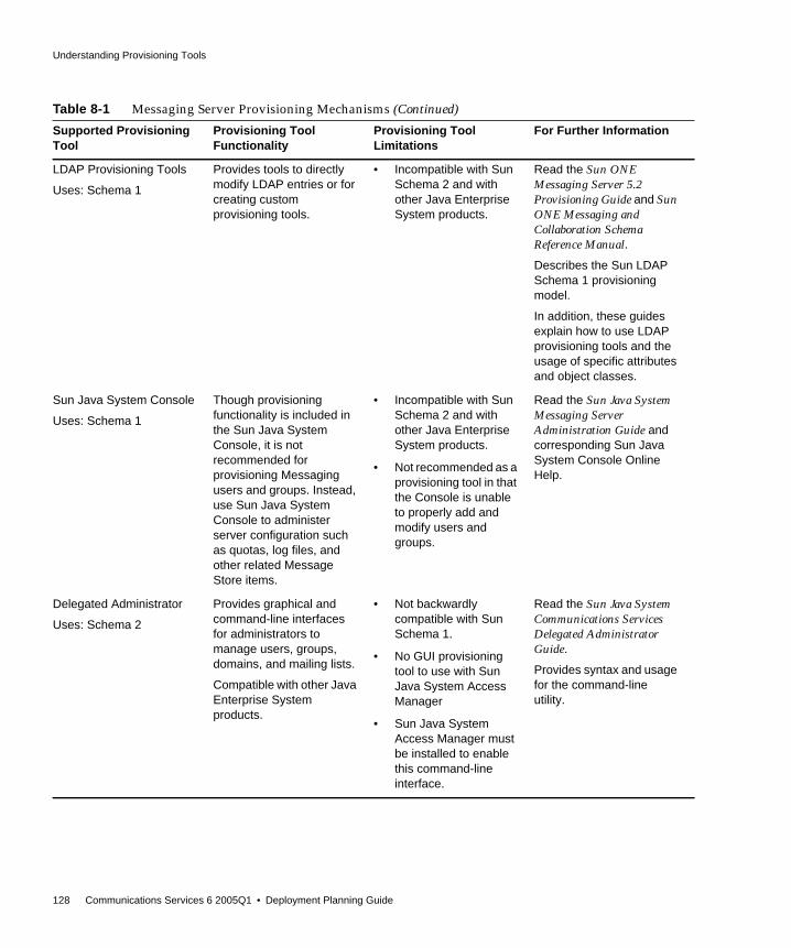
Understanding Provisioning Tools
128 Communications Services 6 2005Q1 • Deployment Planning Guide
LDAP Provisioning Tools
Uses: Schema 1
Provides tools to directlymodify LDAP entries or forcreating customprovisioning tools.
• Incompatible with SunSchema 2 and withother Java EnterpriseSystem products.
Read the Sun ONEMessaging Server 5.2Provisioning Guide and SunONE Messaging andCollaboration SchemaReference Manual.
Describes the Sun LDAPSchema 1 provisioningmodel.
In addition, these guidesexplain how to use LDAPprovisioning tools and theusage of specific attributesand object classes.
Sun Java System Console
Uses: Schema 1
Though provisioningfunctionality is included inthe Sun Java SystemConsole, it is notrecommended forprovisioning Messagingusers and groups. Instead,use Sun Java SystemConsole to administerserver configuration suchas quotas, log files, andother related MessageStore items.
• Incompatible with SunSchema 2 and withother Java EnterpriseSystem products.
• Not recommended as aprovisioning tool in thatthe Console is unableto properly add andmodify users andgroups.
Read the Sun Java SystemMessaging ServerAdministration Guide andcorresponding Sun JavaSystem Console OnlineHelp.
Delegated Administrator
Uses: Schema 2
Provides graphical andcommand-line interfacesfor administrators tomanage users, groups,domains, and mailing lists.
Compatible with other JavaEnterprise Systemproducts.
• Not backwardlycompatible with SunSchema 1.
• No GUI provisioningtool to use with SunJava System AccessManager
• Sun Java SystemAccess Manager mustbe installed to enablethis command-lineinterface.
Read the Sun Java SystemCommunications ServicesDelegated AdministratorGuide.
Provides syntax and usagefor the command-lineutility.
Table 8-1 Messaging Server Provisioning Mechanisms (Continued)
Supported ProvisioningTool
Provisioning ToolFunctionality
Provisioning ToolLimitations
For Further Information

Understanding Provisioning Tools
Chapter 8 Understanding Schema and Provisioning Options 129
Understanding Calendar Server ProvisioningToolsThrough supported Calendar Server provisioning tools, you can query, modify,add, or delete user, group, and domain entry information in your LDAP directory.This section examines these Calendar Server provisioning tools.
In addition to the questions asked in “Deciding Which Schema to Use for CalendarServer” on page 123, you should use Table 8-2 on page 130 to evaluate yourschema and provisioning tool options.
The following sections provide high-level information about the supportedprovisioning tools:
• LDAP Provisioning Tools for Messaging Server
• Delegated Administrator and Calendar Server
• Comparing Messaging Server Provisioning Tool Options
LDAP Provisioning Tools for Calendar ServerSchema 1 users and groups can be provisioned using the LDAP Directory tools(Schema 2 is not supported). You can directly provision users and groups byadding, removing, and modifying the LDIF records through LDAP without havingto use a user interface.
Delegated Administrator and Calendar ServerAccess Manager uses Schema 2. Because the Sun Java System component productsin the Java Enterprise System product suite use Schema 2, use the CommunicationsServices 6 Delegated Administrator utility (command-line interface). This shouldparticularly be the case if you are using more than one Java Enterprise Systemproduct, or if you are performing a brand new installation of Calendar Server.
NOTE Prior to installing and configuring Calendar Server, you need todecide upon a schema model and tool or tools for provisioning yourCalendar Server entries.
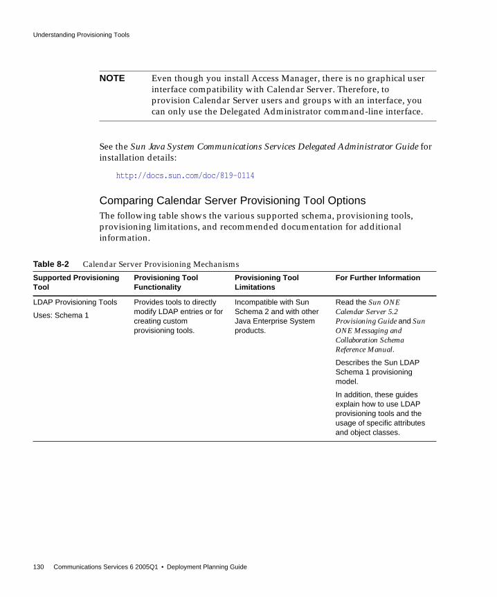
Understanding Provisioning Tools
130 Communications Services 6 2005Q1 • Deployment Planning Guide
See the Sun Java System Communications Services Delegated Administrator Guide forinstallation details:
http://docs.sun.com/doc/819-0114
Comparing Calendar Server Provisioning Tool OptionsThe following table shows the various supported schema, provisioning tools,provisioning limitations, and recommended documentation for additionalinformation.
NOTE Even though you install Access Manager, there is no graphical userinterface compatibility with Calendar Server. Therefore, toprovision Calendar Server users and groups with an interface, youcan only use the Delegated Administrator command-line interface.
Table 8-2 Calendar Server Provisioning Mechanisms
Supported ProvisioningTool
Provisioning ToolFunctionality
Provisioning ToolLimitations
For Further Information
LDAP Provisioning Tools
Uses: Schema 1
Provides tools to directlymodify LDAP entries or forcreating customprovisioning tools.
Incompatible with SunSchema 2 and with otherJava Enterprise Systemproducts.
Read the Sun ONECalendar Server 5.2Provisioning Guide and SunONE Messaging andCollaboration SchemaReference Manual.
Describes the Sun LDAPSchema 1 provisioningmodel.
In addition, these guidesexplain how to use LDAPprovisioning tools and theusage of specific attributesand object classes.

Understanding Provisioning Tools
Chapter 8 Understanding Schema and Provisioning Options 131
Delegated Administrator
Uses: Schema 2
Provides a command-lineinterface for administratorsto manage users, groups,domains, and mailing lists.
Compatible with other JavaEnterprise Systemproducts.
Note: Currently, there is nographical interface formanaging Calendar Serverprovisioning. You must usethe command-lineinterface.
• Not backwardlycompatible with SunSchema 1.
• No GUI provisioningtool to use with SunJava System AccessManager
• Sun Java SystemAccess Manager mustbe installed to enablethis command-lineinterface.
Read the Sun Java SystemCommunications ServicesDelegated AdministratorGuide.
Provides syntax and usagefor the command-lineutility.
Table 8-2 Calendar Server Provisioning Mechanisms (Continued)
Supported ProvisioningTool
Provisioning ToolFunctionality
Provisioning ToolLimitations
For Further Information

Understanding Provisioning Tools
132 Communications Services 6 2005Q1 • Deployment Planning Guide

Part II
Deploying Messaging Server
Chapter 9, “Introduction to Messaging Server Software”
Chapter 10, “Planning a Messaging Server Sizing Strategy”
Chapter 11, “Developing a Messaging Server Architecture”
Chapter 12, “Designing a Messaging Server Topology”
Chapter 13, “Planning Messaging Server Security”
Chapter 14, “Planning a Messaging Server Anti-Spam andAnti-Virus Strategy”
Chapter 15, “Understanding Messaging Server Pre-InstallationConsiderations and Procedures”


135
Chapter 9
Introduction to Messaging ServerSoftware
Sun Java System Messaging Server is a powerful Internet messaging serverdesigned for high-capacity, reliable handling of the messaging needs of bothenterprises and service providers. The server consists of several modular,independently configurable components that provide support for several emailprotocols.
Messaging Server uses a centralized LDAP database for storing information aboutusers, groups, and domains. Some information about server configuration is storedin the LDAP database. Some information is stored in a set of local configurationfiles.
The Messaging Server product suite provides tools to support user provisioningand server configuration.
This chapter contains the following sections:
• What Is a Messaging System?
• Messaging Server Support for Standards and Functionality
• Messaging Server Software Architecture
What Is a Messaging System?A good email system architecture quickly delivers email with embedded sound,graphics, video files, and HTML forms, while providing for future upgrade andscalability. At a simplistic level, the Messaging Server architecture should:
• Accept incoming mail from external sites

Messaging Server Support for Standards and Functionality
136 Communications Services 6 2005Q1 • Deployment Planning Guide
• Determine the user mailbox to deliver these messages to and route themaccordingly
• Accept incoming mail from internal hosts
• Determine the destination system to deliver these messages to and route themaccordingly
Central to an email system architecture is the messaging server itself, a collection ofcomponents used to send and deliver messages. In addition to componentsprovided in Messaging Server, the email system also requires an LDAP server anda DNS server. The DNS server must be in place before deploying your emailsystem.
Several factors other than efficiency and scalability influence the Messaging Serverarchitecture. Specifically these are:
• Load balancing
• Firewalls
• High availability
See Chapter 11, “Developing a Messaging Server Architecture” for moreinformation on these topics.
Messaging Server Support for Standards andFunctionality
This section describes standards supported by Messaging Server, as well as othersupported functionality.
Support for Standard ProtocolsMessaging Server supports most national, international, and industry standardsrelated to electronic messaging. For a complete list, see Appendix A of the Sun JavaSystem Messaging Server Administration Reference:
http://docs.sun.com/doc/819-0106
Messaging Server Support for Standards and Functionality
Chapter 9 Introduction to Messaging Server Software 137
Support for Hosted DomainsMessaging Server provides full support for hosted domains—email domains thatare outsourced by an ISP. That is, the ISP provides email domain hosting for anorganization by operating and maintaining the email services for that organizationremotely. A hosted domain can share the same Messaging Server host with otherhosted domains. In earlier LDAP-based email systems, a domain was supported byone or more email server hosts. With Messaging Server, many domains can behosted on a single server. For each hosted domain, there is an LDAP entry thatpoints to the user and group container for the domain and provides variousdomain-specific default settings.
When you define a domain, there must be a corresponding domain entry in thedirectory, that is, you must have an LDAP entry for the domain. Attributes such asmailAlternateAddress and mailEquivalentAddress depend on the existence ofdomain entries in the directory. Contrast this with vanity domains, which aredomain names associated with an individual user, not with a specific server orhosted domain. The vanity domain does not have an LDAP entry for the domainname.
Support for User ProvisioningMessaging Server uses a centralized LDAP database for storing information aboutusers, groups, and domains. At this time, Messaging Server supports two schemaoptions, Sun Java System LDAP Schema version 1 (Schema 1) and Sun Java SystemLDAP Schema version 2 (Schema 2). The provisioning options will depend onwhich schema you have chosen. See Chapter 15, “Understanding Messaging ServerPre-Installation Considerations and Procedures” for more information.
Messaging Server provisioning for Schema 2 is done using DelegatedAdministrator, as documented in the Sun Java System Communications ServicesDelegated Administrator Guide:
http://docs.sun.com/doc/819-0114
Schema 1 is supported by the iPlanet Delegated Administrator for Messagingproduct, which provides a graphical user interface and a set of command-lineutilities for managing the users, groups, and domains within an organization. Youcan also use the following documentation, pertaining to previous softwarereleases, for managing users, groups, and domains in Schema 1:
NOTE Because of their increased operational overhead, vanity domains arenot recommended.

Messaging Server Support for Standards and Functionality
138 Communications Services 6 2005Q1 • Deployment Planning Guide
• iPlanet Messaging Server Provisioning Guide - Describes how to create domain,user, group, or administrator entries using LDAP:
http://docs.sun.com/doc/816-6018-10
• iPlanet Messaging and Collaboration Schema Reference Manual - Describes Schema1 for Communications Services:
http://docs.sun.com/doc/816-6021-10
• iPlanet Messaging Server Reference Manual - Describes the iPlanet DelegatedAdministrator command-line utilities for managing users, groups, anddomains:
http://docs.sun.com/doc/816-6020-10
• iPlanet Delegated Administrator online help
Support for Unified MessagingMessaging Server provides the basis for a complete unified messaging solution: theconcept of using a single message store for email, voicemail, fax, video, and otherforms of communication.
NOTE Access Manager console provides minimal Messaging Server andCalendar Server LDAP user entry provisioning using AccessManager Services. Because the interface provides no inputvalidation, user entries that cannot receive email or otherwise don’tfunction will be created without reporting any errors. As a result,use this interface for demonstration purposes only.
Delegated Administrator, which is described in the Sun Java SystemCommunications Services Delegated Administrator Guide, is therecommended mechanism for provisioning CommunicationsServices users:
http://docs.sun.com/doc/819-0114
Messaging Server Support for Standards and Functionality
Chapter 9 Introduction to Messaging Server Software 139
Support for WebmailMessaging Server currently supports two client user interfaces (UI):
• Messenger Express
• Communications Express
Going forward, no new features will be added to the Messenger Express userinterface. It has been deprecated in favor of the Communications Express userinterface. Sun Microsystems, Inc. will announce an end-of-life timeline forMessenger Express at a future date.
See the Communications Express documentation for more information:
http://docs.sun.com/coll/MessagingServer_05q1
Messaging Server Security and Access ControlMessaging Server provides the following security and access control features:
• Support for password login and certificate-based login to POP, IMAP, HTTP,or SMTP
• Support for standard security protocols: Transport Layer Security (TLS),Secure Sockets Layer (SSL) and Simple Authentication and Security Layer(SASL)
• Delegated administration
• Client IP address access filters to POP, IMAP, SMTP, and HTTP
• Filtering of unsolicited bulk email using system-wide, per-user, andserver-side Sieve rules
Messaging Server Administration UserInterfacesMessaging Server consists of several modular, independently configurablecomponents that provide support for email transport and access protocols.

Messaging Server Software Architecture
140 Communications Services 6 2005Q1 • Deployment Planning Guide
To configure the Message Transfer Agent (MTA), Messaging Server provides acomplete set of command-line utilities and configuration files stored locally on theserver. To configure the Message Store and message access services, MessagingServer provides a console graphical user interface and a complete set ofcommand-line utilities.
See the Sun Java System Messaging Server Administration Guide for moreinformation:
http://docs.sun.com/doc/819-0105
Messaging Server Software ArchitectureFigure 9-1 on page 141 shows a simplified standalone view of Messaging Server.While this particular deployment is not recommended for large deploymentbecause it does not scale well, it does illustrate the individual components of theserver.

Messaging Server Software Architecture
Chapter 9 Introduction to Messaging Server Software 141
Figure 9-1 Standalone Messaging Server, Simplified Components View
The preceding figure shows the following Messaging Server software components:
• Message Transfer Agent or MTA. Receives, routes, transports, and deliversmail messages using the SMTP protocol. An MTA delivers messages to a localmailbox or to another MTA.
MessageStore
imap pophttp
Message Access Servers
deliverySMTP
Messaging Server
Mail Clients
SMTPsubmission
RetrievalIMAP/POP/HTTP
DNSServer
MTA
DirectoryServer(LDAP)
Message flow
DNS/Directory information flow
Bold text = Messaging Protocols
Internet

Messaging Server Software Architecture
142 Communications Services 6 2005Q1 • Deployment Planning Guide
• Message Store. Consists of a set of components that store, retrieve, andmanipulate messages for mail clients. Mail can be retrieved by POP, IMAP, orHTTP clients. POP clients download messages to the client machine forreading and storage. IMAP and HTTP clients read and manipulate messageson the server.
• LDAP directory. Stores, retrieves, and distributes mail directory informationfor Messaging Server. This includes user routing information, distribution lists,configuration data, and other information necessary to support delivery andaccess of email. The LDAP directory also stores passwords, and any otherinformation needed by the MTA or Message Store to authenticate users.
In addition to storing messages, the Message Store uses the directory server toverify user login name and passwords for mail clients accessing their mail. Thedirectory also stores information about quota limits, default message storetype, and so on.
• DNS Server. Translates domain names into IP addresses. This componentneeds to be present before Messaging Server is installed.
Message Path Through the SimplifiedMessaging Server SystemIncoming messages from the Internet or local clients are received by the MTAthrough the Simple Mail Transport Protocol (SMTP). If the address is internal, thatis, within the Messaging Server domain, the MTA delivers the message to theMessage Store. If the message is external, that is, addressed to a domain outside ofMessaging Server control, the MTA relays the message to another MTA on theInternet.
Although it is possible to deliver mail to the /var/mail file system (UNIX systemsonly), local messages are usually delivered to the more optimized MessagingServer Message Store. Messages are then retrieved by IMAP4, POP3, or HTTP mailclient programs.
Outgoing messages from mail clients go directly to the MTA, which sends themessage to the appropriate server on the Internet. If the address is local, the MTAsends the message to the Message Store.
New users and groups are created by adding user and group entries to thedirectory. Entries can be created or modified by using the CommunicationsServices Delegated Administrator utility or by modifying the directory usingLDAP.

Messaging Server Software Architecture
Chapter 9 Introduction to Messaging Server Software 143
Messaging Server components can be administered by the Administration Serverconsole. In addition, Messaging Server provides a set of command-line interfacesand configuration files. Some of the more common administrative tasks are adding,modifying, and removing users and groups to the mail system, and configuring theoperation of the MTA, directory server, and Message Store.
The Message Transfer Agent (MTA)The MTA routes, transfers, and delivers Internet mail messages for MessagingServer. Mail flows through interfaces known as channels. Each channel consists ofone or a pair of agent programs and a set of configuration information. The agentprograms are a slave program, which handles mail coming into the channel, and amaster program, which handles mail as it leaves the channel. There is a messagequeue for storing messages that are destined to be sent to one or more of theinterfaces associated with any channel. Messaging Server provides a number ofdefault channels, including:
• SMTP Channel. Enables TCP/IP-based message delivery and receipt. Bothmaster and slave channels are provided.
• LMTP Channel. Enables routing of messages directly from MTAs to theMessage Store in a two-tiered configuration. These channels communicatewith the Message Store on another system over LMTP instead of SMTP. Bothmaster and slave channels are provided.
• Pipe Channel. Used for alternative message delivery programs. Enablesdelivery of messages to programs such as a mail sorter rather than directly to auser’s inbox. A master channel is provided.
• Local Channel. Delivers mail to /var/mail. Provides for compatibility witholder UNIX mail clients. A master channel is provided.
• Reprocessing Channel. Useful for messages that are resubmitted. A masterchannel is provided.
• Defragmentation Channel. Reassembles partial messages into the originalcomplete message to support the MIME message/partial content type. Amaster channel is provided.
• Conversion Channel. Performs body part by body part conversion onmessages. Useful for rewriting addresses or re-formatting messages. A masterchannel is provided.
• Message Store Channel. Provides for local delivery to the message store.
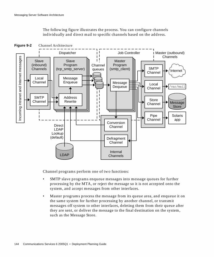
Messaging Server Software Architecture
144 Communications Services 6 2005Q1 • Deployment Planning Guide
The following figure illustrates the process. You can configure channelsindividually and direct mail to specific channels based on the address.
Figure 9-2 Channel Architecture
Channel programs perform one of two functions:
• SMTP slave programs enqueue messages into message queues for furtherprocessing by the MTA, or reject the message so it is not accepted onto thesystem, and accept messages from other interfaces.
• Master programs process the message from its queue area, and enqueue it onthe same system for further processing by another channel, or transmitmessages off system to other interfaces, deleting them from their queue afterthey are sent, or deliver the message to the final destination on the system,such as the Message Store.
SMTPChannel
LocalChannel
StoreChannel
PipeChannel
MessageDequeue
MasterProgram
(smtp_client)
Job Controller
MessageStore
LDAP
Master (outbound)Channels
Direct LDAP
Lookup(default)
Internet
LocalChannel
SMTPChannel
Slave(inbound)Channels
ConversionChannel
DefragmentChannel
InternalChannels
MessageEnqueue
AddressRewrite
SlaveProgram
(tcp_smtp_server)
Dispatcher
Channelqueues
Solarisapp
/var/mail
Inco
min
g In
tran
et a
nd In
tern
et m
essa
ges

Messaging Server Software Architecture
Chapter 9 Introduction to Messaging Server Software 145
Channels are configurable by using the imta.cnf configuration text file. Throughchannel configuration, you can set a variety of channel keywords to control howmessages are handled. Channel keywords affect performance tuning as well asreporting aspects of the system. For example, you can define multiple channels tosegment traffic by destination, define message size limits to limit traffic, and definedelivery status notification rules according to the needs of your business.Diagnostic attributes are also configurable on a per-channel basis. The number ofconfiguration parameters that can be set on a channel basis is large.
See the Sun Java System Messaging Server Administration Guide for moreinformation on MTA concepts:
http://docs.sun.com/doc/819-0105
Direct LDAP LookupThe MTA looks up the information directly from the LDAP server. The directlookup provides a scalable, fast, and configurable relationship between the MTAand the LDAP server. The results of the LDAP queries are cached in the process,with configurable size and time, so performance is tunable. See the Sun Java SystemMessaging Server Administration Guide for more information.
Rewrite RulesMail is routed to a channel based on the result of running the destination addressesthrough domain rewriting rules, or rewrite rules for short. Rewrite rules are used toconvert addresses into true domain addresses and to determine theircorresponding channels. These rules are used to rewrite addresses appearing inboth the transport layer and the message header. The transport layer is the message’senvelope. It contains routing information and is invisible to the user, but is theactual information used to deliver the message to the appropriate recipient.
The rewrite rules and the table of channels cooperate to determine the dispositionof each address. The result of the rewrite process is a rewritten address and arouting system, that is, the system (channel) to which the message is to besent/queued. Depending upon the topology of the network, the routing systemmight only be the first step along the path the message takes to reach itsdestination, or it might be the final destination system itself.
After the rewrite process has finished, a search is made for the routing systemamong the channel portion of the imta.cnf file. Each channel has one or more hostnames associated with it. The routing system name is compared against each ofthese names to determine to which channel to enqueue the message. A simplerewrite rule is shown here:
example.com $U%example.com@tcp_siroe-daemon

Messaging Server Software Architecture
146 Communications Services 6 2005Q1 • Deployment Planning Guide
This rule matches addresses for the domain example.com only. Such matchingaddresses would be rewritten using the template $U%$D, where:
Thus, a message of the form [email protected] would be rewritten [email protected], and would be sent to the channel whose channel hostname is tcp_siroe-daemon.
Rewrite rules can perform sophisticated substitutions based on mapping tables,LDAP directory lookups, and database references. While occasionally cryptic, theyare useful in the fact that they operate at a low level and impose little directoverhead on the message processing cycle. For full information on these and otherfeatures available in the rewrite process, see the Sun Java System Messaging ServerAdministration Guide:
http://docs.sun.com/doc/819-0105
The Job ControllerMaster channel programs are run under the control of the job controller, a programthat controls the message queues and invokes the channel programs to do theactual message delivery. The job controller is a multithreaded process and is one ofthe few processes that is always present in the Messaging Server system. Thechannel processing jobs themselves are created by the job controller but aretransient and might not be present when there is no work for them to do.
Job controller configuration settings determine if there is always at least oneinstance of a channel processing program. In many cases, these are set so that thereis always at least one instance of the service program even when there is noimmediate work to do. In other cases, there will be an instance for a set period oftime after it last did some work but there is nothing to do currently.
Slave channels, which accept external messages, by queueing a message, notify thejob controller of a newly created message file. The job controller enters thisinformation into its internal data structure and if necessary creates a masterchannel job to process the message in that queue. This job creation might not benecessary if the job controller determines that an existing channel job can process
$U Indicates the user portion or left-hand side of the address (beforethe @)
% Indicates the @ sign
$D Indicates the domain portion or right-hand side of the address (afterthe @)

Messaging Server Software Architecture
Chapter 9 Introduction to Messaging Server Software 147
the newly queued message file. When the master channel job starts, it gets itsmessage assignment from the job controller. When it is finished with the message,the master channel updates the job controller as to the status of its processing. Thestatus is either that the message is successfully dequeued or the message should berescheduled for retrying.
The job controller maintains information about message priority and previousdelivery attempts that failed, allowing for advantageous scheduling of channeljobs. The job controller also keeps track of the state of each job. The state can beidle, how long the job has been idle, or whether the job is busy. Tracking stateenables the job controller to keep an optimal pool of channel jobs.
DispatcherThe dispatcher is another process that is always present on a Messaging Serversystem. It is a multithreaded traffic dispatcher, which dispatches incoming SMTPor LMTP connections to the pool of SMTP or LMTP server threads forprotocol-specific processing. The SMTP and LMTP servers programs provide apool of worker threads at the disposal of the dispatcher. After it processes amessage by either rejecting the message or enqueuing it into its destinationchannel, the worker thread is ready to accept more work from the dispatcher.
The dispatcher can block incoming traffic based on IP address and throttles it toprevent denial of service attacks. It also creates and shuts down SMTP or LMTPserver processes based on load and configuration. Therefore the SMTP or LMTPslave channel programs are under the control of the dispatcher, not the jobcontroller.
Local Mail Transfer Protocol (LMTP)As of the Messaging Server 6.0 release, you can configure LMTP for delivery to theMessage Store in a multi-tiered deployment. In these scenarios, where you areusing inbound relays and back-end Message Stores, the relays become responsiblefor address expansion and delivery methods such as autoreply and forwardingand also for mailing list expansion.
NOTE There are currently only two slave channels, SMTP slave and LMTPslave. These programs are controlled by the dispatcher, which isdescribed next.
Messaging Server Software Architecture
148 Communications Services 6 2005Q1 • Deployment Planning Guide
Delivery to the back-end stores historically has been over SMTP, which requiresthe back-end system to look up the recipient addresses in the LDAP directoryagain, thereby engaging the full machinery of the MTA. For speed and efficiency,the MTA can use LMTP rather than SMTP to deliver messages to the back-endstore. See the Sun Java System Messaging Server Administration Guide for moreinformation:
http://docs.sun.com/doc/819-0105
The Message StoreThe Message Store is a dedicated data store for the delivery, retrieval, andmanipulation of Internet mail messages. The Message Store works with the IMAP4and POP3 client access servers to provide flexible and easy access to messaging.The Message Store also works through the HTTP server (mshttpd) to providemessaging capabilities to Communications Express in a web browser. In additionto this section, see the Sun Java System Messaging Server Administration Guide formore information.
The Message Store is organized as a set of folders or user mailboxes. The folder ormailbox is a container for messages. Each user has an INBOX where new mailarrives. Each IMAP or Webmail user can also have one or more folders where mailcan be stored. Folders can contain other folders arranged in a hierarchical tree.Mailboxes owned by an individual user are private folders. Private folders can beshared at the owner’s discretion with other users on the same Message Store.Messaging Server supports sharing folders across multiple stores by using theIMAP protocol.
There are two general areas in the Message Store, one for user files and another forsystem files. In the user area, the location of each user’s INBOX is determined byusing a two-level hashing algorithm. Each user mailbox or folder is represented byanother directory in its parent folder. Each message is stored as a file. When thereare many messages in a folder, the system creates hash directories for that folder.Using hash directories eases the burden on the underlying file system when there
NOTE By design, LMTP is intended for use in multi-tier deployments. It isnot possible to use LMTP with single-system deployments. Also, theMessaging Server’s LMTP service as implemented is not designed towork with other LMTP servers or other LMTP clients.

Messaging Server Software Architecture
Chapter 9 Introduction to Messaging Server Software 149
are many messages in a folder. In addition to the messages themselves, theMessage Store maintains an index and cache of message header information andother frequently used data to enable clients to rapidly retrieve mailbox informationand do common searches without the need to access the individual message files.
A Message Store can contain many message store partitions for user files. AMessage Store partition is contained by a file system volume. As the file systembecomes full, you can create additional file system volumes and Message Storepartitions on those file system volumes to store new users.
The Message Store maintains only one copy of each message per partition. This issometimes referred to as a single-copy message store. When the Message Storereceives a message addressed to multiple users or a group or distribution list, itadds a reference to the message in each user’s INBOX. Rather than saving a copy ofthe message in each user’s INBOX, Message Store avoids the storage of duplicatedata. The individual message status flag (seen, read, answered, deleted, and so on)is maintained per folder for each user.
The system area contains information on the entire Message Store in a databaseformat for faster access. The information in the system area can be reconstructedfrom the user area. Messaging Server contains a database snapshot function. Whenneeded, you can quickly recover the database to a known state. Messaging Serveralso has fast recovery, so that in case of database corruption, you can shut downthe Message Store and bring it back immediately without having to wait for alengthy database reconstruction.
NOTE If the partition gets full, users on the partition will not be able tostore additional messages. There are several ways to address theproblem:
• Reduce the size of user mailboxes
• If you are using volume management software, add additionaldisks
• Create additional partitions and move mailboxes to the newpartitions
For more information, see the “Managing the Message Store”chapter in the Sun Java System Messaging Server AdministrationGuide:
http://docs.sun.com/doc/819-0105

Messaging Server Software Architecture
150 Communications Services 6 2005Q1 • Deployment Planning Guide
The Message Store supports per-user quotas. Enforcement of quota can be turnedon or off. You can configure a user quota by using number of bytes or number ofmessages. You can also set a threshold so that if the quota reaches the threshold, awarning message can be sent to the user. When the user is over quota, newmessages can be held up for retry during a grace period. After the grace period,messages sent to the over-quota user are returned to the sender with anon-delivery notification.
For special applications where quota is used, but messages must be deliveredregardless of the quota status of the users, there is a guaranteed message deliverychannel. This channel can be used to deliver all messages regardless of quotastatus. Utilities are available for reporting quota usage and for sending over quotawarnings.
Messaging Server and Directory ServicesMessaging Server is bundled with Sun Java System Directory Server. DirectoryServer is a Lightweight Directory Access Protocol (LDAP) directory service.Directory Server provides the central repository for information critical to theoperation of Messaging Server. This information includes user profiles,distribution lists, and other system resources.
Directory Information TreeThe directory stores data in the form of a tree, known as the Directory InformationTree (DIT). The DIT is a hierarchical structure, with one major branch at the top ofthe tree and branches and subbranches below. The DIT is flexible enough to enableyou to design a deployment that fits your organization’s needs. For example, youmight choose to arrange the DIT according to your actual business organizationalstructure, or by the geographical layout of your business. You also might want todesign a DIT that follows a one-to-one mapping to your DNS layers. Use care whendesigning your DIT, as changing it after the fact is not an easy task.
The DIT is also flexible enough to accommodate a wide range of administrationscenarios. You can administer the DIT in either a centralized or distributedmanner. In centralized administration, one authority manages the entire DIT. Youwould use centralized administration where the entire DIT resides on one mailserver. In distributed administration, multiple authorities manage the DIT. Usuallyyou implement distributed administration when the DIT is divided into portions,or subtrees, residing on different mail servers.
Messaging Server Software Architecture
Chapter 9 Introduction to Messaging Server Software 151
When the DIT is large, or when mail servers are geographically disbursed, considerdelegating management of portions of the DIT. Typically, you assign an authorityto manage each subtree of the DIT. Messaging Server enables you to managemultiple subtrees from one authority. However, for security reasons, an authoritycan only make changes to the subtree of the DIT that the authority owns.
The default schema used by Messaging Server when Access Manager is not used isdifferent from the one used by Access Manager. Messaging Server supports bothSun Java System LDAP Schema 1 and 2, and allows for transition and migration ofthe schemas.
Directory ReplicationDirectory Server supports replication, enabling a variety of configurations thatprovide redundancy and efficiency. Enabling replication of all or part of the DITfrom one host to other hosts provides the following configuration capabilities:
• The directory information is more accessible, because it is replicated onmultiple servers rather than on a single server.
• The directory information can be cached on a local directory server, reducingeffort of accessing the information from a remote directory server. Caching thedirectory information enhances performance, especially in deployments withlimited network bandwidth to the central directory.
• Depending on the actual configuration, multiple directory servers can processmail client requests faster than a single centralized server.
For more information on directory replication, directory performance tuning, andDIT structure and design, see the Sun Java System Directory Serverdocumentation:
http://docs.sun.com/db/coll/DirectoryServer_05q1
Provisioning Messaging UsersSee Chapter 8, “Understanding Schema and Provisioning Options” for informationon schema and provisioning options for Messaging Server users.

Messaging Server Software Architecture
152 Communications Services 6 2005Q1 • Deployment Planning Guide

153
Chapter 10
Planning a Messaging Server SizingStrategy
When you design your deployment, you must decide how to configure yourMessaging Server to provide optimum performance, scalability, and reliability.
Sizing is an important part of this effort. The sizing process enables you to identifywhat hardware and software resources are needed so that you can deliver yourdesired level of service or response time according to the estimated workload thatyour Messaging Server users generate. Sizing is an iterative effort.
This chapter introduces the basics of sizing your Messaging Server deployment toenable you to obtain the right sizing data by which you can make deploymentdecisions. It also provides the context and rationale for the Messaging Server sizingprocess.
The chapter contains the following sections:
• Collecting Messaging Server Sizing Data
• Using a Messaging Server Load Simulator
• Assessing Your Messaging Server System Performance
• Developing Messaging Server Architectural Strategies
NOTE Because each deployment has its own set of unique features, thischapter does not provide detailed sizing information for yourspecific site. Rather, this chapter explains what you need to considerwhen you architect your sizing plan. Work with your Sun technicalrepresentative for your deployment hardware and software needs.

Collecting Messaging Server Sizing Data
154 Communications Services 6 2005Q1 • Deployment Planning Guide
Collecting Messaging Server Sizing DataUse this section to identify the data you need to size your Messaging Serverdeployment. The following topics are covered in this section:
• Determining Messaging Peak Volume
• Creating Your Messaging Usage Profile
• Defining Your Messaging User Base
Determining Messaging Peak VolumeYour peak volume is the largest concentrated numbers of transactions to yourmessaging system within a given period in a day. The volume can vary from site tosite as well as across different classes of users. For example, peak volume among acertain class of managers in a medium-sized enterprise might occur from 9 to 10 inthe morning, 12 to 1 in the afternoon, and 5 to 6 in the evening.
Analyzing peak volume involves three basic operations:
1. Determining when and for how long the peaks occur
2. Sizing your deployment against peak volume load assumptions
Once patterns are analyzed, choices can be made to help the system handle theload and provide the services that users demand.
3. Making sure that your Messaging Server deployment can support the peakvolume that you have determined.
Creating Your Messaging Usage ProfileMeasuring your load is important for accurate sizing. Your usage profile determinesthe factors that programs and processes place on your Messaging Server hosts.
This section helps you create your usage profile to measure the amount of load thatis placed on your deployment.
To create a usage profile, answer the following questions:
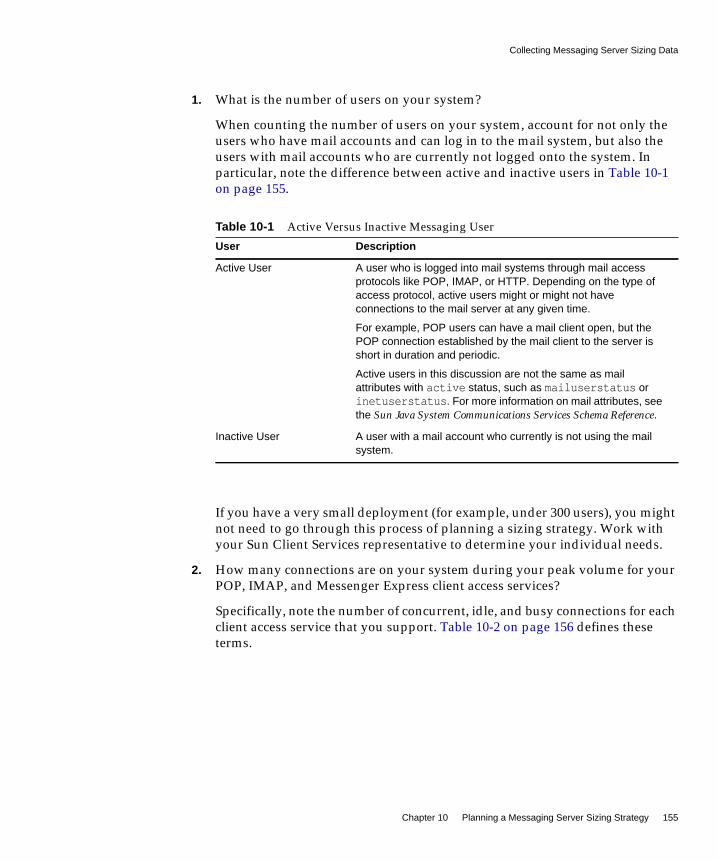
Collecting Messaging Server Sizing Data
Chapter 10 Planning a Messaging Server Sizing Strategy 155
1. What is the number of users on your system?
When counting the number of users on your system, account for not only theusers who have mail accounts and can log in to the mail system, but also theusers with mail accounts who are currently not logged onto the system. Inparticular, note the difference between active and inactive users in Table 10-1on page 155.
If you have a very small deployment (for example, under 300 users), you mightnot need to go through this process of planning a sizing strategy. Work withyour Sun Client Services representative to determine your individual needs.
2. How many connections are on your system during your peak volume for yourPOP, IMAP, and Messenger Express client access services?
Specifically, note the number of concurrent, idle, and busy connections for eachclient access service that you support. Table 10-2 on page 156 defines theseterms.
Table 10-1 Active Versus Inactive Messaging User
User Description
Active User A user who is logged into mail systems through mail accessprotocols like POP, IMAP, or HTTP. Depending on the type ofaccess protocol, active users might or might not haveconnections to the mail server at any given time.
For example, POP users can have a mail client open, but thePOP connection established by the mail client to the server isshort in duration and periodic.
Active users in this discussion are not the same as mailattributes with active status, such as mailuserstatus orinetuserstatus. For more information on mail attributes, seethe Sun Java System Communications Services Schema Reference.
Inactive User A user with a mail account who currently is not using the mailsystem.
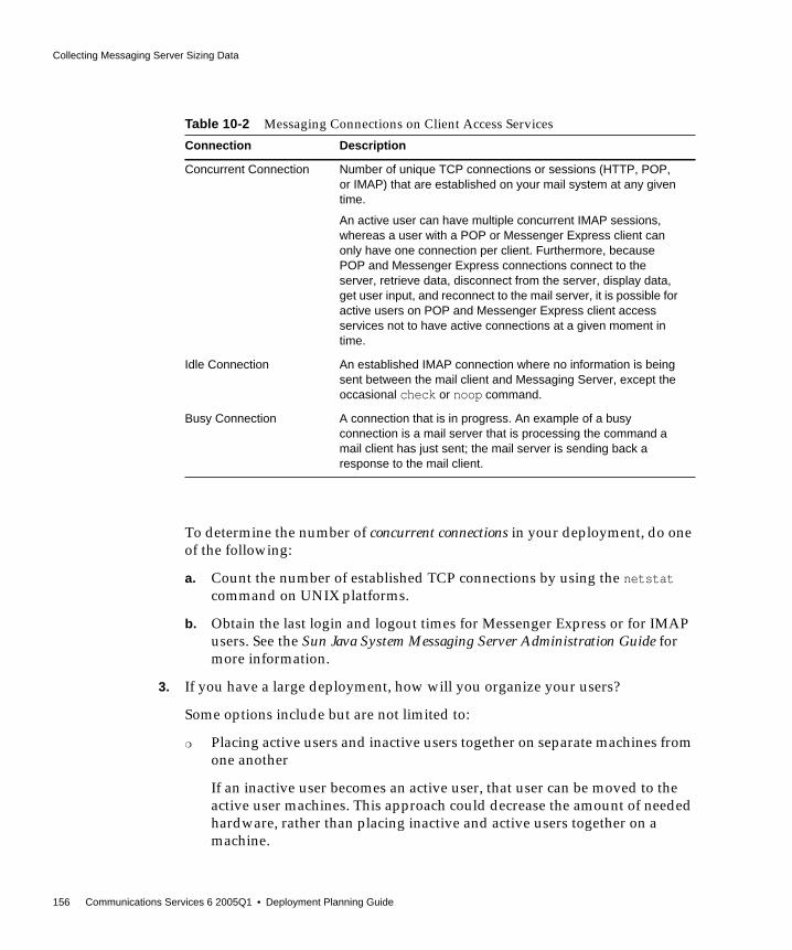
Collecting Messaging Server Sizing Data
156 Communications Services 6 2005Q1 • Deployment Planning Guide
To determine the number of concurrent connections in your deployment, do oneof the following:
a. Count the number of established TCP connections by using the netstatcommand on UNIX platforms.
b. Obtain the last login and logout times for Messenger Express or for IMAPusers. See the Sun Java System Messaging Server Administration Guide formore information.
3. If you have a large deployment, how will you organize your users?
Some options include but are not limited to:
❍ Placing active users and inactive users together on separate machines fromone another
If an inactive user becomes an active user, that user can be moved to theactive user machines. This approach could decrease the amount of neededhardware, rather than placing inactive and active users together on amachine.
Table 10-2 Messaging Connections on Client Access Services
Connection Description
Concurrent Connection Number of unique TCP connections or sessions (HTTP, POP,or IMAP) that are established on your mail system at any giventime.
An active user can have multiple concurrent IMAP sessions,whereas a user with a POP or Messenger Express client canonly have one connection per client. Furthermore, becausePOP and Messenger Express connections connect to theserver, retrieve data, disconnect from the server, display data,get user input, and reconnect to the mail server, it is possible foractive users on POP and Messenger Express client accessservices not to have active connections at a given moment intime.
Idle Connection An established IMAP connection where no information is beingsent between the mail client and Messaging Server, except theoccasional check or noop command.
Busy Connection A connection that is in progress. An example of a busyconnection is a mail server that is processing the command amail client has just sent; the mail server is sending back aresponse to the mail client.

Collecting Messaging Server Sizing Data
Chapter 10 Planning a Messaging Server Sizing Strategy 157
❍ Separating users by Class of Service
You might separate individual contributors, managers, and executives onmachines that offer different mail storage space allocation for each class ofservice, different privileges, and specialized services.
4. What is the amount of storage used on each mailbox?
When you measure the amount of storage per mailbox, you should estimatereal usage per mailbox, not the specified quota. Messages in trash orwastebasket folders still take up disk space and quota.
5. How many messages enter your messaging system from the Internet?
The number of messages should be measured in messages per second duringyour peak volume.
6. How many messages are sent by your users to:
❍ End users on your mail system?
❍ The Internet?
This number of messages is also measured in messages per second during thepeak volume.
7. What is the distribution of messages in different size ranges?
For example:
❍ Less than 5 Kbytes?
❍ Between 5 Kbytes - 10 Kbytes?
❍ Between 10 Kbytes -100 Kbytes?
❍ Between 100 Kbytes - 500 Kbytes?
❍ Between 500 Kbytes -10 MB?
❍ Greater than 10 MB?
If the distribution of message sizes is not available, use the average messagesize on your mail system, however it is not as effective as size ranges.
The size of messages is particularly important, because it affects the rate ofdelivery of the MTA, the rate of delivery into the Message Store, the rate ofmessage retrieval, and processing by anti-virus or anti-spam filters.

Collecting Messaging Server Sizing Data
158 Communications Services 6 2005Q1 • Deployment Planning Guide
8. Will you be using SSL/TLS? If yes, what percentage of users and what type ofusers?
For example, in a particular organization, 20 percent of IMAP connectionsduring peak hours will enable SSL.
9. Do you plan on using any SSL crypto accelerator hardware?
10. Will you be using virus scanning or other specialized message processing andwill this processing be enabled for all users?
Depending on your Messaging Server configuration, the MTA will need toscan all messages to match criteria specified in specialized processing, thusincreasing load on the system.
11. For POP users, will you have a policy restricting how often they can accessmail? If so, how often?
12. For IMAP users, will you enforce a standard client or allow users to choosetheir own?
Different IMAP clients make different numbers of concurrent connections tothe server. Thus, a power user with many open folders might have manyconcurrent connections.
13. Will you allow users to share folders? If so, will you allow all users or onlysome?
Answering these questions provides a preliminary usage profile for yourdeployment. You can refine your usage profile as your Messaging Server needschange.
Additional QuestionsWhile the following questions are not applicable to creating your usage profile,they are important to developing your sizing strategy. How you answer thesequestions might require you to consider additional hardware.
1. How much redundancy do you want in your deployment?
For example, you might consider high availability. Consider how much downtime is allowed, and if you need clustering technology.
2. What backup and restore strategy do you have in place (such as disasterrecovery, mailbox restores, and site failover)? What are the expected times toaccomplish recovery tasks?
Collecting Messaging Server Sizing Data
Chapter 10 Planning a Messaging Server Sizing Strategy 159
3. Do you need a DMZ to separate your internal and external networks? Are allusers using the internal network? Or do some of them connect by using theInternet?
You might need proxy servers (MMP, MEM) and separate MTA layers.
4. What are your response time requirements? What are your throughputrequirements?
5. What is your specific criteria for resource utilization? Can your CPUs be 80percent busy on average? Or only at peak?
6. Will you have messaging servers at different geographic locations? Do youexpect users’ mail to be located geographically?
7. Do you have archiving requirements for keeping mail messages for a certainlength of time?
8. Do you have legal requirements to log all messages? Do you need to keep acopy of every message sent and received?
Defining Your Messaging User BaseOnce you establish a usage profile, compare it to sample pre-defined user basesthat are described in this section. A user base is made up of the types of messagingoperations that your users will perform along with a range of message sizes thatyour users will send and receive. Messaging users fall into one of five user bases:
• Lightweight POP
• Heavyweight POP
• Lightweight IMAP
• Mediumweight IMAP
• Mediumweight Messenger Express/Communications Express
The sample user bases described in this section broadly generalize user behavior.Your particular usage profile might not exactly match the user bases. You will beable to adjust these differences when you run your load simulator (as described in“Using a Messaging Server Load Simulator” on page 161).
Collecting Messaging Server Sizing Data
160 Communications Services 6 2005Q1 • Deployment Planning Guide
Lightweight POPA lightweight POP user base typically consists of residential dial-up users withsimple messaging requirements. Each concurrent client connection sendsapproximately four messages per hour. These users read and delete all of theirmessages within a single login session. In addition, these users compose and sendfew messages of their own with just single recipients. Approximately 80 percent ofmessages are 5 Kbytes or smaller in size, and about 20 percent of messages are 10Kbytes or larger.
Heavyweight POPA heavyweight POP user base typically consists of premium broadband users orsmall business accounts with more sophisticated messaging requirements than thelightweight POP user base. This group uses cable modem or DSL to access itsservice provider. Each concurrent client connection sends approximately sixmessages per hour. Messages average about two recipients per message. Sixty-fivepercent of messages are 5 Kbytes or smaller in size. Thirty percent of messages inthis user base are between 5-10 Kbytes. Five percent of messages are larger than 1Mbyte. Of these users, 85 percent delete all of their messages after reading them.However, 15 percent of users leave messages on the server through several loginsbefore they delete them. Mail builds up in a small portion of those mailboxes. Insome cases, the same message can be fetched several times from the server.
Lightweight IMAPA lightweight IMAP user base represents users that enable premium broadbandInternet services, including most of the advanced features of their messagingsystems like message searching and client filters. This user base is similar toheavyweight POP with regard to message sizes, number of recipients, and numberof messages sent and received by each concurrent connection. Lightweight IMAPusers typically log in for hours at a time and delete most or all mail before log out.Consequently, mail stacks up in a mailbox during a login session, but usergenerally do not store more than 20 to 30 messages in their mailboxes. Mostinboxes contain less than 10 messages.
Mediumweight IMAPA mediumweight IMAP user base represents sophisticated enterprise users withlogin sessions lasting most of an eight hour business day. These users send, receive,and keep a large amount of mail. Furthermore, these users have unlimited or verylarge message quotas. Their inboxes contain a large amount of mail that growsduring the day, and is fully or partially purged in large spurts. They regularly file

Using a Messaging Server Load Simulator
Chapter 10 Planning a Messaging Server Sizing Strategy 161
messages into folders and search for messages multiple times per hour. Eachconcurrent client connection sends approximately eight messages per hour. Theseusers send messages with an average of four recipients and have the same messagesize mix as the Heavyweight POP and Lightweight IMAP user bases.
Mediumweight Messenger Express/Communications ExpressA mediumweight Messenger Express/Communications Express user base issimilar to Mediumweight IMAP. This user base has the same message size mix asMediumweight IMAP, Lightweight IMAP, and Heavyweight POP. And, themessage delivery rates are the same as Mediumweight IMAP users.
It is likely that you will have more than one type of user base in your organization,particularly if you offer more than one client access option. Once you identify youruser bases from these categories, you will test them with your usage profile andwith a load simulator, described in “Using a Messaging Server Load Simulator.”
Using a Messaging Server Load SimulatorTo measure the performance of your Messaging Server, use your messaging userbases (described in “Defining Your Messaging User Base” on page 159) and yourmessaging usage profile (described in “Creating Your Messaging Usage Profile” onpage 154) as inputs into a load simulator.
A load simulator creates a peak volume environment and calibrates the amount ofload placed on your servers. You can determine if you need to alter your hardware,throughput, or deployment architecture to meet your expected response time,without overloading your system.
➤ To Use a Load Simulator
1. Define the user base that you want to test (for example, Lightweight IMAP).
If necessary, adjust individual parameters to best match your usage profile.
2. Define the hardware that will be tested.
3. Run the load simulator and measure the maximum number of concurrentconnections on the tested hardware with the user base.
4. Publish your results and compare those results with production deployments.
5. Repeat this process using different user bases and hardware until you get theresponse time that is within an acceptable range for your organization underpeak load conditions.

Assessing Your Messaging Server System Performance
162 Communications Services 6 2005Q1 • Deployment Planning Guide
Assessing Your Messaging Server SystemPerformance
Once you evaluate your hardware and user base with a load simulator, you need toassess your system performance. The following topics address methods by whichyou can improve your overall system performance.
Messaging Server Memory UtilizationMake sure you have an adequate amount of physical memory on each machine inyour deployment. Additional physical memory improves performance and enablesthe server to operate at peak volume. Without sufficient memory, MessagingServer cannot operate efficiently without excessive swapping.
At minimum, be sure to have 1 GB of memory per CPU. For most deployments,you will want 2 GB of memory per CPU with UltraSPARC® III systems.
Messaging Server Disk ThroughputDisk throughput is the amount of data that your system can transfer from memoryto disk and from disk to memory. The rate at which this data can be transferred iscritical to the performance of Messaging Server. To create efficiencies in yoursystem’s disk throughput:
• Consider your maintenance operations, and ensure you have enoughbandwidth for backup. Backup can also affect network bandwidth particularlywith remote backups. Private backup networks might be a more efficientalternative.
• Carefully partition the store and separate store data items (such as tmp and db)to improve throughput efficiency.
• Ensure the user base is distributed across RAID (Redundant Array ofIndependent Disks) environments in large deployments.
NOTE Contact Sun Client Services for recommended load simulators andsupport.

Assessing Your Messaging Server System Performance
Chapter 10 Planning a Messaging Server Sizing Strategy 163
• Stripe data across multiple disk spindles in order to speed up operations thatretrieve data from disk.
• Allocate enough CPU resources for RAID support, if RAID does not exist onyour hardware.
You want to measure disk I/O in terms of IOPS (total I/Os per second) notbandwidth. You need to measure the number of unique disk transactions thesystem can handle with a very low response time (less than 10 milliseconds).
Messaging Server Disk CapacityWhen planning server system disk space, you need to be sure to include space foroperating environment software, Messaging Server software, and message contentand tracking. Be sure to use an external disk array if availability is a requirement.For most systems, external disks are required for performance because the internalsystem disks supply no more than four spindles.
For the Message Store partitions, the storage requirement is the total size of allmessages plus 30 percent overhead.
In addition, user disk space needs to be allocated. Typically, this space isdetermined by your site’s policy.
Messaging Server Network ThroughputNetwork throughput is the amount of data at a given time that can travel throughyour network between your client application and server. When a networkedserver is unable to respond to a client request, the client typically retransmits therequest a number of times. Each retransmission introduces additional systemoverhead and generates more network traffic.
You can reduce the number of retransmissions by improving data integrity, systemperformance, and network congestion:
NOTE Your deployment planning needs to include how you want to backup the Message Store for disaster recovery. Messaging Serversupports Solstice Backup (Legato Networker), the imsbackup utility,and file system snapshot backup. You might want to store yourbackup media remotely. The more frequently you perform abackup, the better, as long as it doesn’t impact server operations.

Developing Messaging Server Architectural Strategies
164 Communications Services 6 2005Q1 • Deployment Planning Guide
• To avoid bottlenecks, ensure that the network infrastructure can handle theload.
• Partition your network. For example, use 100 Mbps Ethernet for client accessand 1 GB Ethernet for the backbone.
• To ensure that sufficient capacity exists for future expansion, don’t usetheoretical maximum values when configuring your network.
• Separate traffic flows on different network partitions to reduce collisions andto optimize bandwidth use.
Messaging Server CPU ResourcesEnable enough CPU for your Message Stores, MTAs, and on systems that are justrunning multiplexing services (MMP and Messenger Express Multiplexor). Inaddition, enable enough CPU for any RAID systems that you plan to use.
Developing Messaging Server ArchitecturalStrategies
Once you have identified your system performance needs, the next step in sizingyour Messaging Server deployment is to size specific components based on yourarchitectural decisions.
The following sections point out sizing considerations when you deploy two-tieredand one-tiered architectures.
Two-tiered Messaging Server ArchitectureA two-tiered architecture splits the Messaging Server deployment into two layers:an access layer and a data layer. In a simplified two-tiered deployment, you mightadd an MMP and an MTA to the access layer. The MMP acts as a proxy for POPand IMAP mail readers, and the MTA relays transmitted mail. The data layer holdsthe Message Store and Directory Server. Figure 10-1 on page 165 shows asimplified two-tiered architecture.
NOTE For detailed information on planning your architecture, seeChapter 11, “Developing a Messaging Server Architecture.”

Developing Messaging Server Architectural Strategies
Chapter 10 Planning a Messaging Server Sizing Strategy 165
Figure 10-1 Simplified Messaging Server Two-tiered Architecture
Two-tiered architectures have advantages over one-tiered architectures that mightimpact your sizing decisions. Two-tiered architectures permit:
• Easier maintenance than one-tiered architectures
• Offloading of load-intensive processes like SSL, virus scanning, messagereprocessing, and denial of service
• Easier growth management and system upgrade with limited overalldowntime
The next several sections describe how to size specific components in a two-tiereddeployment.
MessageStores
MessageStores
DirectoryServer
AccessLayer
DataLayer
In/OutboundMTA MMP/MEM
Load Balancer
Internet
Mail Clients

Developing Messaging Server Architectural Strategies
166 Communications Services 6 2005Q1 • Deployment Planning Guide
➤ To Size the Message Store
The goals of sizing your Message Store are to identify the maximum number ofconcurrent connections your store can handle and to determine the number ofmessages that can be delivered to the store per second.
1. Determine the number of store machines and concurrent connections permachine based on the figures you gather by using a load simulator. For moreinformation on sizing tools, see “Using a Messaging Server Load Simulator” onpage 161.
2. Determine the amount of storage needed for each store machine.
3. Use multiple store partitions or store machines, if it is appropriate for yourbackup and restoration of file system recovery times.
Sun Client Services is often asked to specify a recommendation for the maximumnumber of users on a message store. Such a recommendation cannot be givenwithout understanding:
• Usage patterns (as described in “Using a Messaging Server Load Simulator” onpage 161).
• The maximum number of active users on any given piece of hardware withinthe deployment.
• Backup, restore, and recovery times. These times increase as the size of amessage store increases.
➤ To Size Inbound and Outbound MTAs
In general, separate your MTA services into inbound and outbound services. Youcan then size each in a similar fashion. The goal of sizing your MTAs is todetermine the maximum number of messages that can be relayed per second.
To size inbound MTAs, you need to know the raw performance of your inboundMTA in a real-world environment.
1. From the raw performance of the inbound MTA, add SSL, virus scanningprocesses, and other extraordinary message processing.
2. Account for denial of service attacks at peak volume in the day.
3. Add enough MTAs for load balancing and for redundancy as appropriate.
With redundancy, one or more of each type of machine can still handle peakload without a substantial impact to throughput or response time.
In addition, sufficient disk capacity for network problems or non-functioningremote MTAs must be calculated for transient messages.

Developing Messaging Server Architectural Strategies
Chapter 10 Planning a Messaging Server Sizing Strategy 167
➤ To Size Your Multiplexing Services
When you size your MMP and MEM, the calculation is based on your system load,particularly the number of POP and IMAP concurrent connections for the MMPand the number of HTTP connections for the MEM.
In addition, you must:
1. Add CPU or a hardware accelerator for SSL on MMP and MEM if appropriate.
2. Add memory to the machine if the MEM is being configured on it.
3. Add more disks for an SMTP proxy for the MMP.
4. Account for denial of service.
5. Add capacity for load balancing and redundancy, if appropriate.
As with inbound MTA routers, one or more of each type of machine shouldstill handle peak load without a substantial impact to throughput or responsetime when you plan for redundancy in your deployment.
Single-tiered Messaging Server ArchitectureIn a single-tiered architecture, there is no separation between access and datalayers. The MTA, Message Store, and sometimes the Directory Server are installedin one layer. Figure 10-2 on page 168 shows a single-tiered architecture.
NOTE These instructions assume that you are installing the MEM and theMMP on the same machine.

Developing Messaging Server Architectural Strategies
168 Communications Services 6 2005Q1 • Deployment Planning Guide
Figure 10-2 Simplified Messaging Server Single-tiered Architecture
Single-tiered architectures have lower up-front hardware costs than two-tieredarchitectures. However, if you choose a one-tiered architecture, you need to allowfor significant maintenance windows.
➤ To Size a Single-tiered Messaging Server Architecture
1. Size your message stores like you size message stores in a “Two-tieredMessaging Server Architecture” on page 164.
2. Add CPU for SSL, if necessary.
3. Account for denial of service attacks.
4. Add more disks for the increased number of SMTP connections.
5. Add more disks for outbound MTA routing.
NOTE For specific instructions on sizing Messaging components insingle-tiered or two-tiered architectures, contact your Sun ClientServices representative.
DirectoryServer
MessagingServer
Mail Clients
Internet

169
Chapter 11
Developing a Messaging ServerArchitecture
This chapter describes how to design the architecture of your Messaging Server,which provides for how Messaging Server components are distributed acrosshardware and software resources.
This chapter contains the following sections:
• Understanding the Two-tiered Messaging Architecture
• Understanding Horizontal and Vertical Scalability in Messaging Server
• Planning for a Highly Available Messaging Server Deployment
• Performance Considerations for a Messaging Server Architecture
Understanding the Two-tiered MessagingArchitecture
A two-tiered messaging architecture provides the optimum design for scalabilityand reliability. Instead of having a single host run all the components of amessaging system, a two-tiered architecture separates the components ontodifferent machines. These separate components perform specific specializedfunctions. As the load for a particular functional component increases—forexample, more Message Storage is required, or more outbound relaying isneeded—you can add more servers to handle the larger loads.
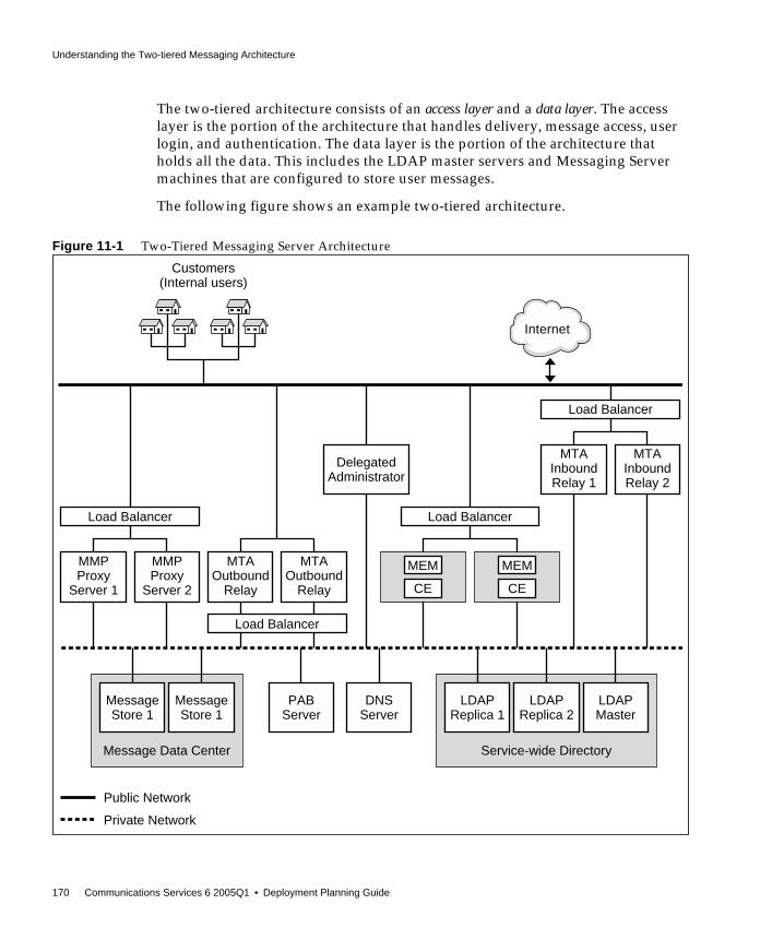
Understanding the Two-tiered Messaging Architecture
170 Communications Services 6 2005Q1 • Deployment Planning Guide
The two-tiered architecture consists of an access layer and a data layer. The accesslayer is the portion of the architecture that handles delivery, message access, userlogin, and authentication. The data layer is the portion of the architecture thatholds all the data. This includes the LDAP master servers and Messaging Servermachines that are configured to store user messages.
The following figure shows an example two-tiered architecture.
Figure 11-1 Two-Tiered Messaging Server Architecture
PABServer
DNSServer
Load Balancer
MMPProxy
Server 1
MMPProxy
Server 2
MTAOutbound
Relay
Load Balancer
MTAOutbound
Relay
DelegatedAdministrator
MEM
CE
MEM
CE
MTAInboundRelay 1
MTAInboundRelay 2
Public Network
Private Network
Customers(Internal users)
MessageStore 1
MessageStore 1
Message Data Center
LDAPReplica 1
LDAPReplica 2
Service-wide Directory
LDAPMaster
Internet
Load Balancer
Load Balancer

Understanding the Two-tiered Messaging Architecture
Chapter 11 Developing a Messaging Server Architecture 171
The following describes each of these functional pieces.
Public Access Network. The network connecting the Messaging Server to internalusers and the Internet. Each deployment defines its own network requirements,however, the basic Messaging Server requirement is connectibility to end users andthe Internet using standard protocols such as SMTP, POP, IMAP, and HTTP.
Private Data Network. This network provides secure connectivity between thepublic access network and Messaging Server data. It consists of a secure accesslayer and a data layer, which includes the service-wide directory, the message datacenter, and the personal address book (PAB) server.
LDAP directory server. Directory server used for storing and retrievinginformation about the user base. It stores user and group aliases, mailhostinformation, delivery preferences, and so on. Depending on your designrequirements, there could be more than one identical directory for the system.Figure 11-1 on page 170 shows a master directory and two replicas. An LDAPdirectory server is provided as part of the Messaging Server product. If desired,you can use data from an existing Sun Java System Directory Server directory. Thedata format of the existing directory must also be compliant with the MessagingServer schema.
Message Store. Holds and stores user mail. Sometimes referred to as a “back end.”The Message Store also refers to the Message Access Components such as theIMAP server, the POP server, and the Webmail (Messenger Express) servers.Figure 11-1 on page 170 shows a deployment that has two message stores. You canadd more stores as needed.
Personal Address Book (PAB) Server. Stores and retrieves users’ addresses in anLDAP server, which can be the same server or a different server from the LDAPserver described above.
DNS server. Maps host names to IP addresses. The DNS server determines whathost to contact when routing messages to external domains. Internally, DNS mapsactual services to names of machines. The DNS server is not part of the MessagingServer product. You must install an operating DNS server prior to installingMessaging Server.
Load Balancer. Balances network connections uniformly or by algorithm acrossmultiple servers. Using load balancers, a single network address can represent alarge number of servers, eliminating traffic bottlenecks, allowing management oftraffic flows and guaranteeing high service levels. Figure 11-1 on page 170 showsload balancers for the MMPs, the MTAs, and the MEMs. Load balancers are not
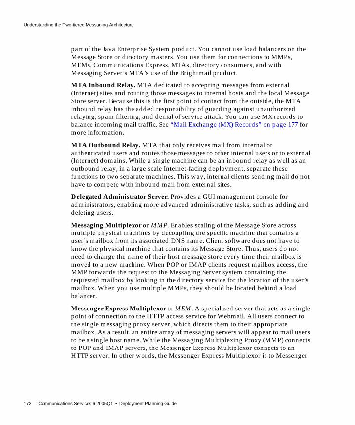
Understanding the Two-tiered Messaging Architecture
172 Communications Services 6 2005Q1 • Deployment Planning Guide
part of the Java Enterprise System product. You cannot use load balancers on theMessage Store or directory masters. You use them for connections to MMPs,MEMs, Communications Express, MTAs, directory consumers, and withMessaging Server’s MTA’s use of the Brightmail product.
MTA Inbound Relay. MTA dedicated to accepting messages from external(Internet) sites and routing those messages to internal hosts and the local MessageStore server. Because this is the first point of contact from the outside, the MTAinbound relay has the added responsibility of guarding against unauthorizedrelaying, spam filtering, and denial of service attack. You can use MX records tobalance incoming mail traffic. See “Mail Exchange (MX) Records” on page 177 formore information.
MTA Outbound Relay. MTA that only receives mail from internal orauthenticated users and routes those messages to other internal users or to external(Internet) domains. While a single machine can be an inbound relay as well as anoutbound relay, in a large scale Internet-facing deployment, separate thesefunctions to two separate machines. This way, internal clients sending mail do nothave to compete with inbound mail from external sites.
Delegated Administrator Server. Provides a GUI management console foradministrators, enabling more advanced administrative tasks, such as adding anddeleting users.
Messaging Multiplexor or MMP. Enables scaling of the Message Store acrossmultiple physical machines by decoupling the specific machine that contains auser’s mailbox from its associated DNS name. Client software does not have toknow the physical machine that contains its Message Store. Thus, users do notneed to change the name of their host message store every time their mailbox ismoved to a new machine. When POP or IMAP clients request mailbox access, theMMP forwards the request to the Messaging Server system containing therequested mailbox by looking in the directory service for the location of the user’smailbox. When you use multiple MMPs, they should be located behind a loadbalancer.
Messenger Express Multiplexor or MEM. A specialized server that acts as a singlepoint of connection to the HTTP access service for Webmail. All users connect tothe single messaging proxy server, which directs them to their appropriatemailbox. As a result, an entire array of messaging servers will appear to mail usersto be a single host name. While the Messaging Multiplexing Proxy (MMP) connectsto POP and IMAP servers, the Messenger Express Multiplexor connects to anHTTP server. In other words, the Messenger Express Multiplexor is to Messenger

Understanding the Two-tiered Messaging Architecture
Chapter 11 Developing a Messaging Server Architecture 173
Express as MMP is to POP and IMAP. When you use multiple MEMs, they shouldbe used with a load balancer. For Communications Express deployments,Communications Express software is also deployed on the same host that containsthe MEM.
Two-tiered Architecture—Messaging Data FlowThis section describes the message flow through the messaging system. How themessage flow works depends upon the actual protocol and message path.
Sending Mail: Internal User to Another Internal UserSynopsis: Internal User -> Load Balancer -> MTA Outbound Relay 1 or 2 -> MTAInbound Relay 1 or 2 -> Message Store 1 or 2
Messages addressed from one internal user to another internal user (that is, userson the same email system) first go to a load balancer. The load balancer shields theemail user from the underlying site architecture and helps provide a highlyavailable email service. The load balancer sends the connection to either MTAOutbound Relay 1 or 2. The outbound relay reads the address and determines thatthe message is addressed to an internal user. The outbound relay sends themessage to MTA Inbound Relay 1 or 2 (or directly to the appropriate message storeif so configured). The MTA Inbound Relay delivers the message to the appropriateMessage Store. The Message Store receives the message and delivers it to themailbox.
Retrieving Mail: Internal UserSynopsis: Internal User -> Load Balancer -> MMP/MEM/CommunicationsExpress Proxy Server 1 or 2 -> Message Store 1 or 2
NOTE An increasingly more common scenario is to use LMTP to delivermail directly from the outbound relay to the store. In a two-tiereddeployment, you can make this choice.

Understanding the Two-tiered Messaging Architecture
174 Communications Services 6 2005Q1 • Deployment Planning Guide
Mail is retrieved by using either POP, HTTP, or IMAP. The user connection isreceived by the load balancer and forwarded to one of the MMP, orMEM/Communications Express servers. The user then sends the login request tothe access machine it is connected to. The access layer machine validates the loginrequest and password, then sends the request over the same protocol designatedby the user connection to the appropriate Message Store (1 or 2). The access layermachine then proxies for the rest of the connection between the client and servers.
Sending Mail: Internal User to an External (Internet) UserSynopsis: Internal User -> Load Balancer -> MTA Outbound Relay 1 or 2 ->Internet
Messages addressed from an internal user to an external user (that is, users not onthe same email system) go to a load balancer. The load balancer shields the emailuser from the underlying site architecture and helps provide a highly availableemail service. The load balancer sends the message to either MTA Outbound Relay1 or 2. The outbound relay reads the address and determines that the message isaddressed to an external user. The outbound relay sends the message to an MTAon the Internet.
Sending Mail: External (Internet) User to an Internal UserSynopsis: External User -> MTA Inbound Relay 1 or 2 -> Message Store 1 or 2
Messages addressed from an external user (from the Internet) to an internal user goto either MTA Inbound Relay 1 or 2 (a load balancer is not required). The inboundrelay reads the address and determines that the message is addressed to an internaluser. The inbound relay determines by using an LDAP lookup whether to send itto Message Store 1 or 2, and delivers accordingly. The appropriate Message Storereceives the message and delivers it to the appropriate mailbox.

Understanding Horizontal and Vertical Scalability in Messaging Server
Chapter 11 Developing a Messaging Server Architecture 175
Understanding Horizontal and Vertical Scalabilityin Messaging Server
Scalability is the capacity of your deployment to accommodate growth in the use ofmessaging services. Scalability determines how well your system can absorb rapidgrowths in user population. Scalability also determines how well your system canadapt to significant changes in user behavior, for example, when a large percentageof your users want to enable SSL within a month.
This section helps you identify the features you can add to your architecture toaccommodate growth on individual servers and across servers. The followingtopics are covered:
• Planning for Horizontal Scalability
• Planning for Vertical Scalability
Planning for Horizontal ScalabilityHorizontal scalability refers to the ease with which you can add more servers toyour architecture. As your user population expands or as user behavior changes,you eventually overload resources of your existing deployment. Careful planninghelps you to determine how to appropriately scale your deployment.
If you scale your deployment horizontally, you distribute resources across severalservers. There are two methods used for horizontal scalability:
• Spreading Your Messaging User Base Across Several Servers
• Spreading Your Messaging Resources Across Redundant Components
Spreading Your Messaging User Base Across Several ServersTo distribute load across servers is to divide clients’ mail evenly across severalback-end Message Stores. You can divide up users alphabetically, by their Class ofService, by their department, or by their physical location and assign them to aspecific back-end Message Store host.
Often, both the MMP and the MEM are placed on the same machine for ease ofmanageability. Figure 11-2 on page 176 shows a sample deployment where usersare spread across multiple back-end servers and multiplexors enabled to handleincoming client connections.

Understanding Horizontal and Vertical Scalability in Messaging Server
176 Communications Services 6 2005Q1 • Deployment Planning Guide
Figure 11-2 Spreading Your User Base Across Multiple Servers
Spreading users across back-end servers provides simplified user management, aslong as you use MMPs or MEMs. Because users connect to one back-end server,where their mail resides, you can standardize setup across all users. Thisconfiguration also makes administration of multiple servers easier to manage.And, as the demand for more Messaging Server hosts increases, you can add morehosts seamlessly.
Client
MessagingServer 1
MessagingServer 2
MessagingServer 3
Multiplexor(MMP and MEM)
Multiplexor(MMP and MEM)
DirectoryServer
LDAP LDAP
Client Client Client Client
POP/IMAP/HTTP
Load Balancer
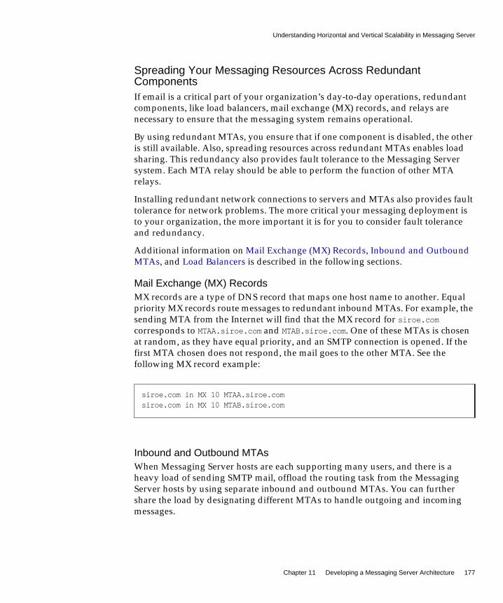
Understanding Horizontal and Vertical Scalability in Messaging Server
Chapter 11 Developing a Messaging Server Architecture 177
Spreading Your Messaging Resources Across RedundantComponentsIf email is a critical part of your organization’s day-to-day operations, redundantcomponents, like load balancers, mail exchange (MX) records, and relays arenecessary to ensure that the messaging system remains operational.
By using redundant MTAs, you ensure that if one component is disabled, the otheris still available. Also, spreading resources across redundant MTAs enables loadsharing. This redundancy also provides fault tolerance to the Messaging Serversystem. Each MTA relay should be able to perform the function of other MTArelays.
Installing redundant network connections to servers and MTAs also provides faulttolerance for network problems. The more critical your messaging deployment isto your organization, the more important it is for you to consider fault toleranceand redundancy.
Additional information on Mail Exchange (MX) Records, Inbound and OutboundMTAs, and Load Balancers is described in the following sections.
Mail Exchange (MX) RecordsMX records are a type of DNS record that maps one host name to another. Equalpriority MX records route messages to redundant inbound MTAs. For example, thesending MTA from the Internet will find that the MX record for siroe.comcorresponds to MTAA.siroe.com and MTAB.siroe.com. One of these MTAs is chosenat random, as they have equal priority, and an SMTP connection is opened. If thefirst MTA chosen does not respond, the mail goes to the other MTA. See thefollowing MX record example:
Inbound and Outbound MTAsWhen Messaging Server hosts are each supporting many users, and there is aheavy load of sending SMTP mail, offload the routing task from the MessagingServer hosts by using separate inbound and outbound MTAs. You can furthershare the load by designating different MTAs to handle outgoing and incomingmessages.
siroe.com in MX 10 MTAA.siroe.comsiroe.com in MX 10 MTAB.siroe.com
Understanding Horizontal and Vertical Scalability in Messaging Server
178 Communications Services 6 2005Q1 • Deployment Planning Guide
Often, both the inbound and outbound MTAs are combined as a single In/OutSMTP host. To determine if you need one or more MTA hosts, identify the inboundand outbound message traffic characteristics of the overall architecture.
Load BalancersLoad balancing can be used to distribute the load across several servers so that nosingle server is overwhelmed. A load balancer takes requests from clients andredirects them to an available server by algorithms such as keeping track of eachserver’s CPU and memory usage. Load balancers are available as software thatruns on a common server, as a pure external hardware solution, or as a combinedhardware and software package.
Planning for Vertical ScalabilityVertical scalability pertains to adding resources to individual server machines, forexample, adding additional CPUs. Each machine is scaled to handle a certain load.In general, you might decide upon vertical scalability in your deployment becauseyou have resource limitations or you are unable to purchase additional hardwareas your deployment grows.
To vertically scale your deployment, you need to:
• Size each messaging component
See “Developing Messaging Server Architectural Strategies” on page 164.
• Test the load of a prototype of your system
See “Using a Messaging Server Load Simulator” on page 161.
• Monitor system performance and adjust the deployment accordingly

Planning for a Highly Available Messaging Server Deployment
Chapter 11 Developing a Messaging Server Architecture 179
Planning for a Highly Available Messaging ServerDeployment
High availability is a design for your deployment that operates with a smallamount of planned and unplanned downtime. Typically, a highly availableconfiguration is a cluster that is made up of two or more loosely coupled systems.Each system maintains its own processors, memory, and operating system. Storageis shared between the systems. Special software binds the systems together andallows them to provide fully automated recovery from a single point of failure.Messaging Server provides high-availability options that support both the SunCluster services and Veritas clustering solutions.
When you create your high availability plan, you need to weigh availability againstcost. Generally, the more highly available your deployment is, the more its designand operation will cost.
High availability is an insurance against the loss of data access due to applicationservices outages or downtime. If application services become unavailable, anorganization might suffer from loss of income, customers, and other opportunities.The value of high availability to an organization is directly related to the costs ofdowntime. The higher the cost of downtime, the easier it is to justify the additionalexpense of having high availability. In addition, your organization might haveservice level agreements guaranteeing a certain level of availability. Not meetingavailability goals can have a direct financial impact.
See Chapter 6, “Designing for Service Availability” for more information.
Performance Considerations for a MessagingServer Architecture
This section describes how to evaluate the performance characteristics ofMessaging Server components to accurately develop your architecture.
This section contains the following topics:
• Message Store Performance Considerations
• MTA Performance Considerations
• MMP Performance Considerations
• MEM Performance Considerations
• Messaging Server and Directory Server Performance Consideration

Performance Considerations for a Messaging Server Architecture
180 Communications Services 6 2005Q1 • Deployment Planning Guide
Message Store Performance ConsiderationsMessage store performance is affected by a variety of factors, including:
1. Disk I/O
2. Inbound message rate (also known as message insertion rate)
3. Message sizes
4. Login rate (POP/IMAP/HTTP)
5. Transaction rate for IMAP and HTTP
6. Concurrent number of connections for the various protocols
7. Network I/O
8. Use of SSL
The preceding factors list the approximate order of impact to the Message Store.Most performance issues with the Message Storage arise from insufficient disk I/Ocapacity. Additionally, the way in which you lay out the store on the physical diskscan also have a performance impact. For smaller standalone systems, it is possibleto use a simple stripe of disks to provide sufficient I/O. For most larger systems,segregate the file system and provide I/O to the various parts of store.
Messaging Server DirectoriesMessaging Server uses six directories that receive a significant amount of input andoutput activity. Because these directories are accessed very frequently, you canincrease performance by providing each of those directories with its own disk, oreven better, providing each directory with a Redundant Array of IndependentDisks (RAID). The following table describes these directories.
Table 11-1 High Access Messaging Server Directories
High I/O Directory Description and Defining Parameter
MTA queue directory In this directory, many files are created, one for each message that passes through theMTA channels. After the file is sent to the next destination, the file is then deleted. Thedirectory location is controlled by the IMTA_QUEUE option in the imta_tailor file.Before modifying the MTA queue directory, read about this option in the Sun Java SystemMessaging Server Administration Reference.
Default location: /var/opt/SUNWmsgrsr/queue

Performance Considerations for a Messaging Server Architecture
Chapter 11 Developing a Messaging Server Architecture 181
The following sections provide more detail on Messaging Server high accessdirectories.
MTA Queue DirectoriesIn non-LMTP environments, the MTA queue directories in the Message Storesystem are also heavily used. LMTP works such that inbound messages are not putin MTA queues but directly inserted into the store. This message insertion lessensthe overall I/O requirements of the Message Store machines and greatly reduces
Messaging Server logdirectory
This directory contains log files which are constantly being appended with new logginginformation. The number of changes will depend on the logging level set. The directorylocation is controlled by the configutil parameter logfile.*.logdir, where * can be alog-generating component such as admin, default, http, imap, or pop. The MTA log filescan be changed with the IMTA_LOG option in the imta_tailor file.
Default location: /var/opt/SUNWmsgsr/log
Mailbox database files These files require constant updates as well as cache synchronization. Put this directoryon your fastest disk volume. These files are always located in the/var/opt/SUNWmsgsr/store/mboxlist directory.
Message store indexfiles
These files contain meta information about mailboxes, messages, and users. By default,these files are stored with the message files. The configutil parameterstore.partition.*.path, where * is the name of the partition, controls the directorylocation. If you have the resources, put these files on your second fastest disk volume.
Default location: /var/opt/SUNWmsgsr/store/partition/primary
Message files These files contain the messages, one file per message. Files are frequently created,never modified, and eventually deleted. By default, they are stored in the same directoryas the message store index files. The location can be controlled with the configutilparameter store.partition.partition_name.messagepath, where partition_name is the nameof the partition.
Some sites might have a single message store partition called primary specified bystore.partition.primary.path. Large sites might have additional partitions that can bespecified with store.partition.partition_name.messagepath, where partition_name is thename of the partition.
Default location: /var/opt/SUNWmsgsr/store/partition/primary
Mailbox list databasetemporary directory
The directory used by the Message Store for all temporary files. To maximizeperformance, this directory should be located under the fastest file system. For Solaris,use the configutil command to configure the store.dbtmpdir variable to a directoryunder tmpfs, for example, /tmp/mboxlist.
Default location: /var/opt/SUNWmsgsr/store/mboxlist
Table 11-1 High Access Messaging Server Directories (Continued)
High I/O Directory Description and Defining Parameter

Performance Considerations for a Messaging Server Architecture
182 Communications Services 6 2005Q1 • Deployment Planning Guide
use of the MTA queue directory on Message Store machines. If the system isstandalone or uses the local MTA for Webmail sends, significant I/O can still resulton this directory for outbound mail traffic. In a two-tiered environment usingLMTP, this directory will be lightly used, if at all. In prior releases of MessagingServer, on large systems this directory set needs to be on its own stripe or volume.
MTA queue directories should usually be on their own file systems, separate fromthe message files in the Message Store. The Message Store has a mechanism to stopdelivery and appending of messages if the disk space drops below a definedthreshold. However, if both the log and queue directories are on the same filesystem and keep growing, you will run out of disk space and the Message Storewill stop working.
Log Files DirectoryThe log files directory requires varying amounts of I/O depending on the level oflogging that is enabled. The I/O on the logging directory, unlike all of the otherhigh I/O requirements of the Message Store, is asynchronous. For typicaldeployment scenarios, do not dedicate an entire LUN for logging. For very largestore deployments, or environments where significant logging is required, adedicated LUN is in order.
In almost all environments, you need to protect the Message Store from loss ofdata. The level of loss and continuous availability that is necessary varies fromsimple disk protection such as RAID5, to mirroring, to routine backup, to real timereplication of data, to a remote data center. Data protection also varies from theneed for Automatic System Recovery (ASR) capable machines, to local HAcapabilities, to automated remote site failover. These decisions impact the amountof hardware and support staff required to provide service.
mboxlist DirectoryThe mboxlist directory is highly I/O intensive but not very large. The mboxlistdirectory contains the databases that are used by the stores and their transactionlogs. Because of its high I/O activity, and due to the fact that the multiple files thatconstitute the database cannot be split between different file systems, you shouldplace the mboxlist directory on its own stripe or volume in large deployments.This is also the most likely cause of a loss of vertical scalability, as manyprocedures of the Message Store access the databases. For highly active systems,this can be a bottleneck. Bottlenecks in the I/O performance of the mboxlistdirectory decrease not only the raw performance and response time of the store butalso impact the vertical scalability. For systems with a requirement for fastrecovery from backup, place this directory on Solid State Disks (SSD) or a highperformance caching array to accept the high write rate that an ongoing restorewith a live service will place on the file system.

Performance Considerations for a Messaging Server Architecture
Chapter 11 Developing a Messaging Server Architecture 183
Multiple Store PartitionsThe Message Store supports multiple store partitions. Place each partition on itsown stripe or volume. The number of partitions that should be put on a store isdetermined by a number of factors. The obvious factor is the I/O requirements ofthe peak load on the server. By adding additional file systems as additional storepartitions, you increase the available IOPS (total IOs per second) to the server formail delivery and retrieval. In most environments, you will get more IOPS out of alarger number of smaller stripes or LUNs than a small number of larger stripes orLUNs.
With some disk arrays, it is possible to configure a set of arrays in two differentways. You can configure each array as a LUN and mount it as a file system. Or, youcan configure each array as a LUN and stripe them on the server. Both are validconfigurations. However, multiple store partitions (one per small array or anumber of partitions on a large array striping sets of LUNs into server volumes)are easier to optimize and administer.
Raw performance, however, is usually not the overriding factor in deciding howmany store partitions you want or need. In corporate environments, it is likely thatyou will need more space than IOPS. Again, it is possible to software stripe acrossLUNs and provide a single large store partition. However, multiple smallerpartitions are generally easier to manage. The overriding factor of determining theappropriate number of store partitions is usually recovery time.
Recovery times for store partitions fall into a number of categories:
• First of all, the fsck command can operate on multiple file systems in parallelon a crash recovery caused by power, hardware, or operating system failure. Ifyou are using a journaling file system (highly recommended and required forany HA platform), this factor is small.
• Secondly, backup and recovery procedures can be run in parallel acrossmultiple store partitions. This parallelization is limited by the verticalscalability of the mboxlist directory as the Message Store uses a single set ofdatabases for all of the store partitions. Store cleanup procedures (expire andpurge) run in parallel with one thread of execution per store partition.
• Lastly, mirror or RAID re-sync procedures are faster with smaller LUNs. Thereare no hard and fast rules here, but the general recommendation in most casesis that a store partition should not encompass more than 10 spindles.
The size of drive to use in a storage array is a question of the IOPS requirementsversus the space requirements. For most residential ISP POP environments, use“smaller drives.” Corporate deployments with large quotas should use “larger”drives. Again, every deployment is different and needs to examine its own set ofrequirements.
Performance Considerations for a Messaging Server Architecture
184 Communications Services 6 2005Q1 • Deployment Planning Guide
Message Store Processor ScalabilityThe Message Store scales well, due to its multiprocess, multithreaded nature. TheMessage Store actually scales more than linearly from one to four processors. Thismeans that a four processor system will handle more load than a set of four singleprocessor systems. The Message Store also scales fairly linearly from four to 12processors. From 12 to 16 processors, there is increased capacity but not a linearincrease. The vertical scalability of a Message Store is more limited with the use ofLMTP although the number of users that can be supported on the same size storesystem increases dramatically.
Setting the Mailbox Database Cache SizeMessaging Server makes frequent calls to the mailbox database. For this reason, ithelps if this data is returned as quickly as possible. A portion of the mailboxdatabase is cached to improve Message Store performance. Setting the optimalcache size can make a big difference in overall Message Store performance. You setthe size of the cache with the configutil parameter store.dbcachesize.
You should use the configutil parameter store.dbtmpdir to redefine the locationof the mailbox database to /tmp, that is, /tmp/mboxlist.
The mailbox database is stored in data pages. When the various daemons makecalls to the database (stored, imapd, popd), the system checks to see if the desiredpage is stored in the cache. If it is, the data is passed to the daemon. If not, thesystem must write one page from the cache back to disk, and read the desired pageand write it in the cache. Lowering the number of disk read/writes helpsperformance, so setting the cache to its optimal size is important.
If the cache is too small, the desired data will have to be retrieved from disk morefrequently than necessary. If the cache is too large, dynamic memory (RAM) iswasted, and it takes longer to synchronize the disk to the cache. Of these twosituations, a cache that is too small will degrade performance more than a cachethat is too large.
Cache efficiency is measured by hit rate. Hit rate is the percentage of times that adatabase call can be handled by cache. An optimally sized cache will have a 99percent hit rate (that is, 99 percent of the desired database pages will be returned tothe daemon without having to grab pages from the disk). The goal is to set thecache so that it holds a number of pages such that the cache will be able to return atleast 95 percent of the requested data. If the direct cache return is less than 95percent, then you need to increase the cache size.
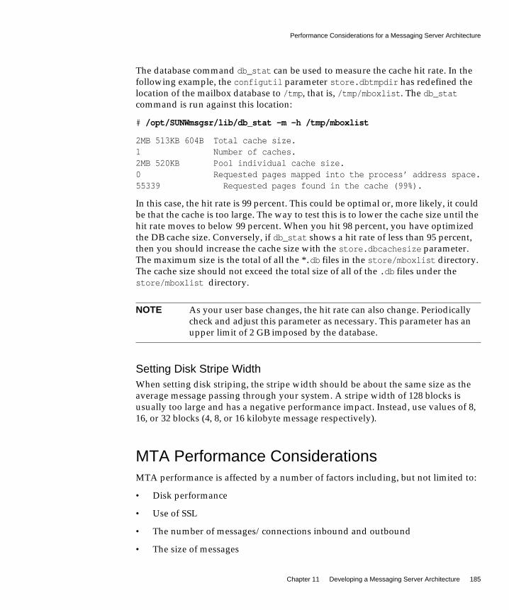
Performance Considerations for a Messaging Server Architecture
Chapter 11 Developing a Messaging Server Architecture 185
The database command db_stat can be used to measure the cache hit rate. In thefollowing example, the configutil parameter store.dbtmpdir has redefined thelocation of the mailbox database to /tmp, that is, /tmp/mboxlist. The db_statcommand is run against this location:
# /opt/SUNWmsgsr/lib/db_stat -m -h /tmp/mboxlist
2MB 513KB 604B Total cache size.1 Number of caches.2MB 520KB Pool individual cache size.0 Requested pages mapped into the process’ address space.55339 Requested pages found in the cache (99%).
In this case, the hit rate is 99 percent. This could be optimal or, more likely, it couldbe that the cache is too large. The way to test this is to lower the cache size until thehit rate moves to below 99 percent. When you hit 98 percent, you have optimizedthe DB cache size. Conversely, if db_stat shows a hit rate of less than 95 percent,then you should increase the cache size with the store.dbcachesize parameter.The maximum size is the total of all the *.db files in the store/mboxlist directory.The cache size should not exceed the total size of all of the .db files under thestore/mboxlist directory.
Setting Disk Stripe WidthWhen setting disk striping, the stripe width should be about the same size as theaverage message passing through your system. A stripe width of 128 blocks isusually too large and has a negative performance impact. Instead, use values of 8,16, or 32 blocks (4, 8, or 16 kilobyte message respectively).
MTA Performance ConsiderationsMTA performance is affected by a number of factors including, but not limited to:
• Disk performance
• Use of SSL
• The number of messages/connections inbound and outbound
• The size of messages
NOTE As your user base changes, the hit rate can also change. Periodicallycheck and adjust this parameter as necessary. This parameter has anupper limit of 2 GB imposed by the database.

Performance Considerations for a Messaging Server Architecture
186 Communications Services 6 2005Q1 • Deployment Planning Guide
• The number of target destinations/messages
• The speed and latency of connections to and from the MTA
• The need to do spam or virus filtering
• The use of Sieve rules and the need to do other message parsing (like use of theconversion channel)
The MTA is both CPU and I/O intensive. The MTA reads from and writes to twodifferent directories: the queue directory and the logging directory. For a smallhost (four processors or less) functioning as an MTA, you do not need to separatethese directories on different file systems. The queue directory is written tosynchronously with fairly large writes. The logging directory is a series of smallerasynchronous and sequential writes. On systems that experience high traffic,consider separating these two directories onto two different file systems.
In most cases, you will want to plan for redundancy in the MTA in the disksubsystem to avoid permanent loss of mail in the event of a spindle failure. (Aspindle failure is by far the single most likely hardware failure.) This implies thateither an external disk array or a system with many internal spindles is optimal.
MTA and RAID Trade-offsThere are trade-offs between using external hardware RAID controller devices andusing JBOD arrays with software mirroring. The JBOD approach is sometimes lessexpensive in terms of hardware purchase but always requires more rack space andpower. The JBOD approach also marginally decreases server performance, becauseof the cost of doing the mirroring in software, and usually implies a highermaintenance cost. Software RAID5 has such an impact on performance that it is nota viable alternative. For these reasons, use RAID5 caching controller arrays ifRAID5 is preferred.
MTA and Processor ScalabilityThe MTA does scale linearly beyond eight processors, and like the Message Store,more than linearly from one processor to four.
MTA and High AvailabilityIt is rarely advisable to put the MTA under HA control, but there are exceptionalcircumstances where this is warranted. If you have a requirement that maildelivery happens in a short, specified time frame, even in the event of hardwarefailure, then the MTA must be put under HA software control. In most

Performance Considerations for a Messaging Server Architecture
Chapter 11 Developing a Messaging Server Architecture 187
environments, simply increase the number of MTAs that are available by one ormore over the peak load requirement. This ensures that proper traffic flow canoccur even with a single MTA failure, or in very large environments, whenmultiple MTAs are offline for some reason.
In addition, with respect to placement of MTAs, you should always deploy theMTA inside your firewall.
MMP Performance ConsiderationsThe MMP runs as a single multithreaded process and is CPU and network bound.It uses disk resources only for logging. The MMP scales most efficiently on twoprocessor machines, scales less than linearly from two to four processors and scalespoorly beyond four processors. Two processor, rack mounted machines are goodcandidates for MMPs.
In deployments where you choose to put other component software on the samemachine as the MMP (MEM, Calendar Server front end, Communications Expressweb container, LDAP proxy, and so on), look at deploying a larger, four processorSPARC machine. Such a configuration reduces the total number of machines thatneed to be managed, patched, monitored, and so forth.
MMP sizing is affected by connection rates and transaction rates. POP sizing isfairly straight forward, as POP connections are rarely idle. POP connectionsconnect, do some work, and disconnect. IMAP sizing is more complex, as you needto understand the login rate, the concurrency rate, and the way in which theconnections are busy. The MMP is also somewhat affected by connection latencyand bandwidth. Thus, in a dial up environment, the MMP will handle a smallernumber of concurrent users than in a broadband environment, as the MMP acts asa buffer for data coming from the Message Store to the client.
If you use SSL in a significant percentage of connections, install a hardwareaccelerator.
MMP and High AvailabilityNever deploy the MMP under HA control. An individual MMP has no static data.In a highly available environment, add one or more additional MMP machines sothat if one or more are down there is still sufficient capacity for the peak load. Ifyou are using Sun Fire Blade™ Server hardware, take into account the possibilitythat an entire Blade rack unit can go down and plan for the appropriateredundancy.
Performance Considerations for a Messaging Server Architecture
188 Communications Services 6 2005Q1 • Deployment Planning Guide
MEM Performance ConsiderationsThe MEM provides a middle-tier proxy for the Webmail (Messenger Express)client. This client enables users to access mail and to compose messages through abrowser. The benefit of the MEM is that end users only connect to the MEM toaccess email, regardless of which back-end server is storing their mail. MEMaccomplishes this by managing the HTTP session information and user profiles viathe user’s LDAP information. The second benefit is that all static files and LDAPauthentication states are located on the Messaging Server front end. This benefitoffsets some of the additional CPU requirements associated with web pagerendering from the Message Store back end.
You can put the MMP and MEM on the same set of servers. The advantage todoing so is if a small number of either MMPs or MEMs are required, the amount ofextra hardware for redundancy is minimized. The only possible downside toco-locating the MMP and MEM on the same set of servers is that a denial of serviceattack on one protocol can impact the others.
Messaging Server and Directory ServerPerformance ConsiderationFor large-scale installations with Access Manager, Messaging Server, and an LDAPSchema 2 directory, you might want to consolidate the Access Control Instructions(ACIs) in your directory.
When you install Access Manager with Messaging Server, a large number of ACIsinitially are installed in the directory. Many default ACIs are not needed or used byMessaging Server. You can improve the performance of Directory Server and,consequently, of Messaging Server look-ups, by consolidating and reducing thenumber of default ACIs in the directory.
For information about how to consolidate and discard unused ACIs, see“Appendix D: ACI Consolidation” in the Sun Java System Communications ServicesDelegated Administrator Guide:
http://docs.sun.com/doc/819-0114
189
Chapter 12
Designing a Messaging ServerTopology
This chapter describes how to design your messaging topology. A messagingtopology describes the physical and logical layout of a networked messagingsystem. Specifically, a topology depicts the way the devices are arranged on anetwork and how they communicate with one another. In addition, a topologydescribes the way that data passes through a network. Topologies are bound tonetwork protocols that direct the data flow.
This chapter contains the following sections:
• Identifying Your Geographic Needs
• Designing a Messaging Topology
• Understanding Messaging Topology Elements
• Creating a Messaging Topology Example
Identifying Your Geographic NeedsThe first step in designing your messaging topology is to identify your geographicneeds. In particular, determine the messaging services you need to provide at eachlocation within your organization:
1. Once you identify your deployment goals, determine the functions andfeatures needed for each location within your deployment.
2. Understand your organization’s physical constraints, specifically:
❍ Available bandwidth
❍ Distance between physical locations within your organization

Designing a Messaging Topology
190 Communications Services 6 2005Q1 • Deployment Planning Guide
❍ Mail transaction rate and volume of mail storage at each physical location
Designing a Messaging TopologyBefore you develop your topology, you need a strategy to determine where you aregoing to put your messaging servers in your organization. Depending on yourgoals, there are four common topologies that you can apply to your organization:
• Central Topology
Consolidates most or all major system components and messaging servers at asingle location.
• Distributed Topology
Spreads most or all system components and messaging servers across multiplesites.
• Hybrid Topology
Consolidates some system components and distributes other componentsacross multiple locations.
• Service Provider Topology
Hosts multiple domains and handles larger customer base. Like a centraltopology, it consolidates most system components at a single location.
Central TopologyIn a central topology, most or all major system components and messagingprocesses are located at one site. Clients at remote sites communicate over a WideArea Network (WAN) to the centralized messaging servers. Figure 12-1 onpage 191 shows a central topology.
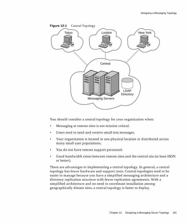
Designing a Messaging Topology
Chapter 12 Designing a Messaging Server Topology 191
Figure 12-1 Central Topology
You should consider a central topology for your organization when:
• Messaging at remote sites is not mission critical.
• Users tend to send and receive small text messages.
• Your organization is located in one physical location or distributed acrossmany small user populations.
• You do not have remote support personnel.
• Good bandwidth exists between remote sites and the central site (at least ISDNor better).
There are advantages to implementing a central topology. In general, a centraltopology has lower hardware and support costs. Central topologies tend to beeasier to manage because you have a simplified messaging architecture and adirectory replication structure with fewer replication agreements. With asimplified architecture and no need to coordinate installation amonggeographically distant sites, a central topology is faster to deploy.
LondonTokyo New York
Messaging Servers
LDAPDirectory
Central

Designing a Messaging Topology
192 Communications Services 6 2005Q1 • Deployment Planning Guide
That said, there are an equal number of disadvantages to implementing a centraltopology. A centralized approach heavily relies on a WAN. If the network does notfunction properly, users at the same site as well as users in remote locations couldnot send email to one another. Depending on network bandwidth and traffic,services might be slower during peak usage times. For users who send messageswithin the same domain, a central topology is inefficient. For example, looking atFigure 12-1 on page 191, a message sent from one user in the Tokyo site would firsttravel to the Central site before being sent to another user in the Tokyo site.
Distributed TopologyIn a distributed topology, most or all system components and messaging processesare distributed across multiple sites, usually at each remote site. Figure 12-2 onpage 193 shows a distributed topology.

Designing a Messaging Topology
Chapter 12 Designing a Messaging Server Topology 193
Figure 12-2 Distributed Topology
You should consider a distributed topology for your site when:
• Messaging at remote sites is mission critical.
• Users send and receive large messages.
• You have large user populations at remote sites.
• Support personnel exists at remote sites.
Messaging Servers
LDAPDirectory
Central
MessagingServer
Tokyo
LDAPDirectory
MessagingServer
New York
LDAPDirectory
MessagingServer
London
LDAPDirectory

Designing a Messaging Topology
194 Communications Services 6 2005Q1 • Deployment Planning Guide
• There is poor bandwidth to remote sites.
If bandwidth significantly impacts your topology strategy, you shouldconsider upgrading the bandwidth. In general, bandwidth is relativelyinexpensive. You might also consider a Virtual Private Networking (VPN),which uses existing high bandwidth Internet pipes rather than dedicated linesbehind a firewall.
There are advantages to implementing a distributed topology. Users at regionalsites have faster access to their messages because they do not have to retrievemessages over the WAN. Furthermore, messages sent within a regional locationwill incur less messaging traffic than in a central topology. However, satelliteoffices still rely on the WAN. Therefore, if lots of message traffic is generated in asatellite office, the WAN might need to be upgraded.
The disadvantages of implementing a distributed topology are that typically youwill have higher hardware costs and higher support costs as you maintain morehardware at more locations. Support costs are also higher because of thecomplexity of the distributed topology. For example, failover in a distributedtopology is more difficult to implement than in a central topology. In addition, it ismuch slower to initially deploy Messaging Server because there are multipleservers spread across multiple sites.
Because Messaging Server accesses the LDAP directory, the LDAP server is acritical link in the mail delivery process. If you don’t use remote LDAP replicas,and the central LDAP is down, the messaging service will not be usable.
Hybrid TopologyIn a hybrid topology, central and distributed topologies are combined to meet theneeds of an organization. Figure 12-3 on page 195 shows a hybrid topology.
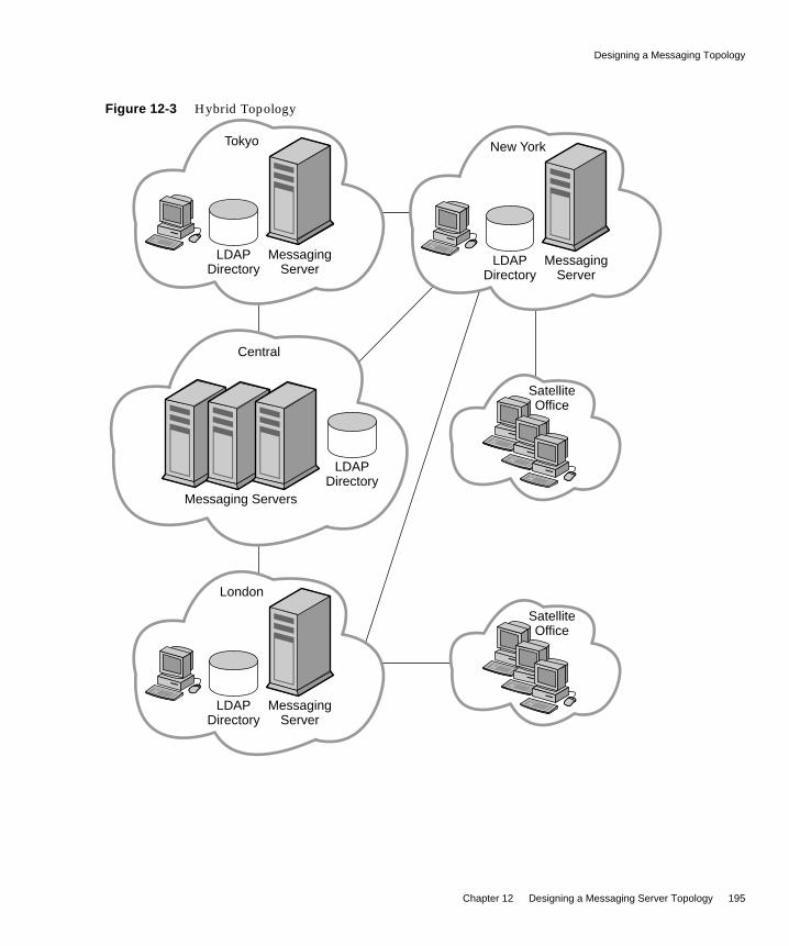
Designing a Messaging Topology
Chapter 12 Designing a Messaging Server Topology 195
Figure 12-3 Hybrid Topology
Messaging Servers
LDAPDirectory
Central
MessagingServer
LDAPDirectory
Tokyo
MessagingServer
LDAPDirectory
New York
MessagingServer
LDAPDirectory
London
SatelliteOffice
SatelliteOffice

Designing a Messaging Topology
196 Communications Services 6 2005Q1 • Deployment Planning Guide
Organizations that benefit from a hybrid topology include those with many sitesthat have the ability to support a large user base. These sites that support them canhouse their own messaging servers. Some of these larger sites might have smallersatellite offices located in the general vicinity. But these satellite offices would notrequire their own messaging servers. Instead, the nearest major office would act asthe central location for their services.
Service Provider TopologyIn essence, a service provider topology is a large-scale central topology. Typically,a service provider hosts multiple domains and has a larger customer base than anenterprise. Systems are centralized and are able to support multiple users duringpeak hours. Figure 12-4 on page 197 shows a service provider topology.
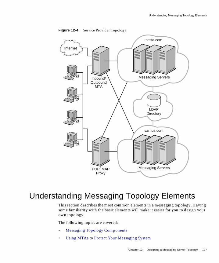
Understanding Messaging Topology Elements
Chapter 12 Designing a Messaging Server Topology 197
Figure 12-4 Service Provider Topology
Understanding Messaging Topology ElementsThis section describes the most common elements in a messaging topology. Havingsome familiarity with the basic elements will make it easier for you to design yourown topology.
The following topics are covered:
• Messaging Topology Components
• Using MTAs to Protect Your Messaging System
LDAPDirectory
Inbound/Outbound
MTA
POP/IMAPProxy
Messaging Servers
varrius.com
Messaging Servers
sesta.com
Internet

Understanding Messaging Topology Elements
198 Communications Services 6 2005Q1 • Deployment Planning Guide
• Using MMPs and MEMs
• Using Gateways
Messaging Topology ComponentsIn “Designing a Messaging Topology” on page 190, you were introduced to threecomponents of a messaging topology: Messaging Server, Directory Server, andclients. This section will describe other components in a basic messaging topology.
Messaging Server. Houses and maintains user mailboxes; it can also be a serverthat contains just the MTA portion of Messaging Server as described inInternet-facing MTA and MTA Relay.
Client. Accesses messaging services from Messaging Server (often through theMessaging Multiplexor).
Directory Server. Used by Messaging Server for name and alias lookup. DirectLDAP lookup determines where messages should be routed.
Messaging Multiplexor. Connects clients to the appropriate Messaging Server forretrieving messages.
Internet-facing MTA. Routes messages from the Internet and relays them acrossthe firewall. Typically, a Messaging Server host is set up to perform this function.
MTA Relay. The inbound MTA routes incoming messages to valid addresses inthe appropriate Messaging Server. The outgoing MTA accepts outgoing messagesfrom clients, queries LDAP to find out where to send the message, then sends it offto the appropriate server or out across the firewall to the Internet. Typically, aMessaging Server host is set up to perform this function.
DNS Server. Resolves server names into IP addresses to allow messages to berouted to their proper address in the network.
Firewall. Restricts Internet access of your internal site. You might even have afirewall between departments in your organization.

Understanding Messaging Topology Elements
Chapter 12 Designing a Messaging Server Topology 199
Using MTAs to Protect Your Messaging SystemYou can use MTAs to protect your Messaging Server deployment, as well as tocontrol the flow of message traffic to and from your site.
An Internet-facing MTA is a single point of contact that receives messages fromsites external to your organization. An Internet-facing MTA sends the incomingmessages across the firewall to the inbound MTA, typically another MessagingServer.
The inbound MTA then queries the directory to determine where to send themessage within the organization. The Internet-facing MTA is located in thedemilitarized zone (DMZ) of the firewall (between the external and internal wallsof the firewall), and does not have access to any information about servers otherthan the inbound MTA.
The outbound MTA accepts outgoing messages from clients. It queries LDAP tofind out where to send the message, then sends it off to the appropriate server orout across the firewall to the Internet. This offloads the MTA work from messagingservers that are used by users to retrieve messages. Figure 12-5 on page 200illustrates the idea.

Understanding Messaging Topology Elements
200 Communications Services 6 2005Q1 • Deployment Planning Guide
Figure 12-5 MTAs in Messaging Topology
Using MMPs and MEMsThe MMP enables you to mask the layout of your Messaging Server hosts fromyour end users. Consequently, you assign users to a generic MMP or a loadbalancer without having them point to the specific server where their mail boxesreside. Message access clients point to the MMP for retrieving incoming messages.
InboundMTA
OutboundMTA
InternetFacing MTA
Internet Firewall
Internet Firewall
Internet

Understanding Messaging Topology Elements
Chapter 12 Designing a Messaging Server Topology 201
When such a client connects and authenticates, the MMP looks up the userinformation in the directory to determine where the user’s messages are held. TheMMP then connects the client to that specific server. The following figure showshow the MMP acts as a proxy for IMAP4 and POP3 connections to Messagingservers. You can multiplex HTTP services (like Messenger Express) by enabling theMEM feature. The following figure shows how multiplexors function in aMessaging Server environment.
Figure 12-6 MMP Overview
Use a load balancer in front of the multiple MMPs. It is unlikely that you wouldhave a single MMP.
Mail Servers
POP, IMAP
POP, IMAP
POP, IMAP
POP, IMAP
ClientsLDAP
LDAP
LDAPDirectory
Load Balancer
Multiplexors

Creating a Messaging Topology Example
202 Communications Services 6 2005Q1 • Deployment Planning Guide
Using GatewaysYour organization might contain legacy messaging systems that use proprietarymethods for messaging handling. Until you migrate your users, both messagingstrategies must co-exist. To access these legacy systems, you can use an SMTPgateway, which enables SMTP connections between the new system and the otherlegacy systems. Usually legacy systems support SMTP connections so that theinbound MTA can route messages to it.
Creating a Messaging Topology ExampleOnce you have a basic understanding of your topological needs, your strategy, andthe topology elements, you can create your messaging topology. To illustrate howto create a messaging topology, this section uses the example of the SiroeCorporation.
The Siroe Corporation is a multimedia organization headquartered in New York,with two smaller offices in Los Angeles and Chicago, and two satellite offices inSan Diego and in Minneapolis.
Step 1: Identifying Messaging GoalsThe first step in creating a topology is to understand the goals of your organization.Similar to Chapter 2, “Analyzing Your Communications Services Requirements,”Siroe’s messaging goals can be categorized into business objectives, technical, andfinancial constraints.
Siroe’s Business ObjectivesThe finance, marketing, legal, IT, and engineering groups are located in New York.The creative groups are located in Los Angeles and in San Diego. The technicalsupport groups are located in Chicago and Minneapolis. Most messages are sentbetween Chicago, Los Angeles, and New York.
Employees at the Siroe Corporation rely on email as their primary method ofcommunication. On average, employees send approximately 15 messages per daywith attachments in the form of spreadsheets, presentations, or animation.
The deployment planners determined that Message Server hosts would be set upin Chicago, Los Angeles, and in New York. Since the volume of email traffic in SanDiego and in Minneapolis is relatively light, these satellite offices will only havemail clients connecting to servers that are located in Chicago and in Los Angeles.
Creating a Messaging Topology Example
Chapter 12 Designing a Messaging Server Topology 203
Siroe’s Financial and Technical ConstraintsBecause of budgetary restrictions, Siroe will be using the existing infrastructureand hardware that is already in place, moving servers to locations where there iscritical need. 24x7 support will be available only in the New York, Chicago, andLos Angeles offices. All offices will be connected by T3 lines to the Internet.
Step 2: Choosing a Topology StrategyThe second step in creating your messaging topology is to choose your topologystrategy, described in “Designing a Messaging Topology” on page 190. The SiroeCorporation evaluated their business objectives as well as their financial andtechnical constraints. They determined that:
• Messaging Server hosts did not need to be deployed at satellite sites, only mailclients.
• Good bandwidth exists at satellite sites (T3 lines).
• Regardless of location, mail users send and receive large messages throughoutthe corporation.
• There are large user populations in New York, Los Angeles, and Chicago, butnot in Minneapolis or San Diego.
• Support personnel exist in New York, Los Angeles, and in Chicago.
The Siroe Corporation then mapped their objectives and constraints to a commondesign strategy. Figure 12-7 on page 204 shows that the Siroe Corporation haschosen a hybrid topology.
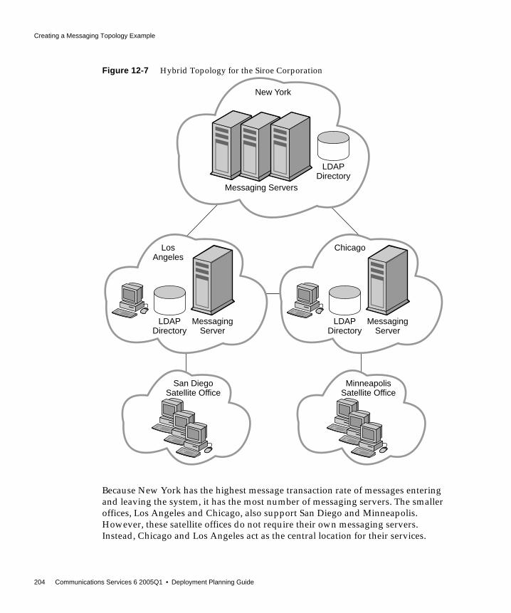
Creating a Messaging Topology Example
204 Communications Services 6 2005Q1 • Deployment Planning Guide
Figure 12-7 Hybrid Topology for the Siroe Corporation
Because New York has the highest message transaction rate of messages enteringand leaving the system, it has the most number of messaging servers. The smalleroffices, Los Angeles and Chicago, also support San Diego and Minneapolis.However, these satellite offices do not require their own messaging servers.Instead, Chicago and Los Angeles act as the central location for their services.
Messaging Servers
LDAPDirectory
New York
MessagingServer
LDAPDirectory
LosAngeles
MessagingServer
LDAPDirectory
Chicago
MinneapolisSatellite Office
San DiegoSatellite Office

Creating a Messaging Topology Example
Chapter 12 Designing a Messaging Server Topology 205
Step 3: Planning the Topology ElementsThe final step in creating your messaging topology is to plan your topologyelements in your actual deployment, as described in “Understanding MessagingTopology Elements” on page 197. The following figure illustrates the topologyelements in the Chicago and Minneapolis offices.
Figure 12-8 Topological Elements in the Siroe Messaging Deployment for Chicago and Minneapolis
Because 30 percent of the workforce is made up of third-party vendors andcontractors, internal firewalls are used in addition to the external firewalls in thetopology to restrict access to locations within the company. Internet MTAs areplaced in the topology to route messages from the Internet and relay them acrossthe firewall. MTAs are added to route incoming and outgoing messages.Separating incoming and outgoing messages helps to manage the high volume of
InternetMail Relays
DMZ Layer
MMP
InboundMail Relays
OutboundMail Relays
MessagingServers
DirectoryServers
ChicagoMail Clients
MinneapolisMail Clients
Internet Firew
all
Internal Firew
all
DNSServer
POPIMAP
Internet Internet
Creating a Messaging Topology Example
206 Communications Services 6 2005Q1 • Deployment Planning Guide
message traffic. The MMP connects employees’ POP and IMAP mail clients to theirmailboxes in the Messaging Servers. By using an MMP, employees don’t have toknow their specific mail host when they log in, and administrators can seamlesslymove employees’ mailboxes to different mail server locations.
Creating a messaging topology enables you to account for the physical and logicalplacement of all the elements in your deployment. Doing so ensures minimalrework of your installation.

207
Chapter 13
Planning Messaging Server Security
This chapter describes how to plan for and protect the various component of yourMessaging Server deployment.
This chapter contains the following sections:
• Protecting Messaging Components in Your Deployment
• Planning Messaging User Authentication
• Planning Message Encryption Strategies
Protecting Messaging Components in YourDeployment
This section describes how to secure components in your Messaging deployment:
Protecting MTAsSecure MTAs to protect processing resources and server availability. Whenmessages are relayed from unauthorized users or large quantities of spam aredelivered, response time is reduced, disk space is used up, and processingresources, which are reserved for end users, are consumed. Not only does spamwaste server resources, it is also a nuisance for your end users.
NOTE With each component, you should use the chroot function to limitthe number of available commands on each machine.

Protecting Messaging Components in Your Deployment
208 Communications Services 6 2005Q1 • Deployment Planning Guide
The following table describes the most common threats to MTAs.
This section on MTA relays describes security options you can use in yourdeployment:
• Access Controls
• Conversion Channels and Third Party Filtering Tools
• RBL Checking
• Client Access Filters
• Monitoring Your Security Strategy
NOTE Not only must you protect your deployment from externalunauthorized users, but you might also have to protect your systemfrom internal users as well.
Table 13-1 Common MTA Security Threats
Threat Description
UBE (Unsolicited BulkEmail) or spam
Refers to the practice of sending electronic junk mail to millions ofusers.
Unauthorized relaying Uses another company’s SMTP server to relay your email.Spammers often use this technique to cover their tracks. End-usersmight send complaints back to the sending relay, not to thespammer.
Mail bombs Characterized by abusers who repeatedly send an identicalmessage to a particular address. The goal is to exceed mailboxquotas with the message.
Email spoofing Creates email that appears to have originated from one sourcewhen it actually was sent from another source.
Denial of service attacks Prevents legitimate users of a service from using that service. Forexample, an attacker attempts to flood a network, therebypreventing legitimate network traffic.

Protecting Messaging Components in Your Deployment
Chapter 13 Planning Messaging Server Security 209
Access ControlsYou can use access controls to reject messages from (or to) certain users at a systemlevel. In addition, you can institute more complex restrictions of message trafficbetween certain users. Also, you might allow users to set up filters on their ownincoming messages (including rejecting messages based on contents of the messageheaders).
If you want to control access with envelope-level controls, use mapping tables tofilter mail. If you want to control access with header-based controls, or if userswish to implement their own personalized controls, use the more general mailboxfilters approach with server-side rules.
Mapping Table OverviewYou can control access to your mail services by configuring certain mapping tables.Many components of the MTA employ table lookup-oriented information. Thistype of table is used to transform, that is, map, an input string into an output string.Mapping tables are usually presented as two columns. The first (left-hand) columnprovides possible input strings against which to match (pattern), and the second(right-hand) column gives the resulting output string for which the input string ismapped (template).
The following table describes these mapping tables, which enable you to controlwho can or cannot send mail, receive mail, or both. See the Sun Java SystemMessaging Server Adminstration Guide for more information:
http://docs.sun.com/doc/819-0105
Table 13-2 Access Control Mapping Tables
Mapping Table Description
SEND_ACCESS Used to block incoming connections based on envelope From:address, envelope To: address, source and destination channels.The To: address is checked after rewriting, alias expansion, and soon, have been performed.
ORIG_SEND_ACCESS Used to block incoming connections based on envelope From:address, envelope To: address, source and destination channels.The To: address is checked after rewriting but before aliasexpansion.
MAIL_ACCESS Used to block incoming connections based on combinedinformation found in SEND_ACCESS and PORT_ACCESS tables: thatis, the channel and address information found in SEND_ACCESScombined with the IP address and port number information found inPORT_ACCESS.

Protecting Messaging Components in Your Deployment
210 Communications Services 6 2005Q1 • Deployment Planning Guide
The following figure illustrates where mapping tables are activated in the mailacceptance process.
Figure 13-1 Mapping Tables and the Mail Acceptance Process
For all the network ports controlled by the MTA service dispatcher, a PORT_ACCESSrejection response, if warranted, takes place at the initial connection from a remotehost. A FROM_ACCESS rejection occurs in response to the MAIL FROM: command,before the sending side can send the recipient information or the message data. ASEND_ACCESS or MAIL_ACCESS rejection occurs in response to a RCPT TO: command,
ORIG_MAIL_ACCESS Used to block incoming connections based on combinedinformation found in ORIG_SEND_ACCESS and PORT_ACCESStables: that is, the channel and address information found inORIG_SEND_ACCESS combined with the IP address and portnumber information found in PORT_ACCESS.
FROM_ACCESS Used to filter mail based on envelope From: addresses. Use thistable if the To: address is irrelevant.
PORT_ACCESS Used to block incoming connections based on IP number.
Table 13-2 Access Control Mapping Tables (Continued)
Mapping Table Description
TCP Connection
ehlo/auth
MAIL FROM:
RCPT TO:
data
PORT_ACCESS Mapping Table(server-address, sever-port, client-address, client-port)
FROM_ACCESS Mapping Table(Port info + submit-type, src-channel, from-address, auth-from)
SEND_ACCESS or ORIG_SEND ACCESS Mapping Tables(src-channel, from-address, dst-channel, to-address)
MAIL_ACCESS or ORIG_MAIL ACCESS Mapping Tables(Port info + Send Info)
SMTP Session

Protecting Messaging Components in Your Deployment
Chapter 13 Planning Messaging Server Security 211
before the sending side gets to send the message data. If an SMTP message isrejected, your Messaging Server never accepts or sees the message data, thusminimizing the overhead of performing such rejections. If multiple access controlmapping tables exist, Messaging Server checks them all.
Configuring Anti-Relaying with Mapping TablesYou can also use access control mappings to prevent people from relaying SMTPmail through your Messaging Server system. For example, someone might try touse your mail system to relay junk mail to thousands of mailboxes on your systemor on other systems.
By default, Messaging Server prevents all SMTP relaying activity, includingrelaying by local POP and IMAP mail clients. If clients do not authenticate by usingSMTP AUTH, as described in “Enabling Authenticated SMTP” on page 220, andattempt to submit messages to external addresses via Messaging Server’s SMTPserver, their submission attempts are rejected. Thus, you will likely want to modifyyour configuration so that it recognizes your own internal systems and subnetsfrom which relaying should always be accepted.
➤ To Prevent Relaying From Outside Hosts
To prevent hosts that reside outside your domain from relaying to other hostsoutside your domain:
1. Split incoming mail into different channels. For example:
❍ IP addresses within your domain go to the tcp_internal channel.
❍ Authenticated sessions go to the tcp_auth channel.
❍ All other mail is sent to the tcp_local channel.
2. Recognize and allow mail from your POP and IMAP clients by using anINTERNAL_IP mapping table, fully explained in the chapter on Mail Filteringand Access Control in the Sun Java System Messaging Server AdministrationGuide.
http://docs.sun.com/doc/819-0105
NOTE If the message is accepted, it can still be filtered by way ofconversion channels and user defined filters.

Protecting Messaging Components in Your Deployment
212 Communications Services 6 2005Q1 • Deployment Planning Guide
Using Mailbox FiltersA filter consists of one or more conditional actions to apply to a message.Messaging Server filters are stored on the server and evaluated by the server. Theyare sometimes called server-side rules (SSR).
You can create channel-level filters and MTA-wide filters to prevent the delivery ofunwanted mail. You can also create filter templates and make them available toend users by using Messenger Express. End users use the templates to buildpersonal mailbox filters to prevent delivery of unwanted mail message to theirmailboxes. The server applies filters in the following priority. See the Sun JavaSystem Messaging Server Administration Guide for more information.
1. Per-user filters
Per-user filters apply to messages destined for a particular user’s mailbox. Youcan create filter templates and make them available to end users by using theMessenger Express client. End users use the templates to build personal serverfilters to manipulate the delivery of mail messages to their mailboxes. Thefilers reject unwanted messages, redirect mail, filter messages into mailboxfolders, and so on.
If a personal mailbox filter explicitly accepts or rejects a message, then filterprocessing for that message finishes.
A filter template generalizes a Sieve script by replacing “hard-coded” elementsof the Sieve script with prompts and input fields. A Java servlet is used to parsethe Sieve templates and generate the user interface in the browser. When anend user supplies values in the input fields, the servlet takes those values andsaves them in a Sieve script in the user’s directory profile entry. The promptsand input fields are presented to the end user through the Messenger Expressinterface.
If the recipient user had no mailbox filter, or if the user’s mailbox filter did notexplicitly apply to the message in question, Messaging Server next applies thechannel-level filter.
Protecting Messaging Components in Your Deployment
Chapter 13 Planning Messaging Server Security 213
2. Channel-level filter
Channel-level filters apply to each message enqueued to a channel. A typicaluse for this type of filter is to block messages going through a specific channel.
To create a channel-level filter, you must write the filter using Sieve. See theMail Filtering and Access Control chapter in the Sun Java System MessagingServer Administration Guide for specific instructions on creating filters withSieve:
http://docs.sun.com/doc/819-0105
If the channel-level filter explicitly accepts or rejects a message, then filterprocessing for that message finishes. Otherwise, Messaging Server next appliesthe MTA-wide filter, if there is one.
3. MTA-wide filter
MTA-wide filters apply to all messages enqueued to the MTA. A typical usefor this type of filter is to block unsolicited bulk email or other unwantedmessages regardless of the messages’ destinations.
To create an MTA-wide filter, you must write the filter using Sieve. See theMail Filtering and Access Control chapter in the Sun Java System MessagingServer Administration Guide for specific instructions on creating filters withSieve:
http://docs.sun.com/doc/819-0105
By default, each user has no mailbox filter. When a user accesses MessengerExpress interface to create one or more filters, then their filters are stored in theLDAP Directory.
Conversion Channels and Third Party Filtering ToolsThe conversion channel performs body-part-by-body-part conversions onmessages through the MTA. This processing can be done by any site-suppliedprograms or command procedures. The conversion channel can do such thingssuch as convert text or images from one format to another, scan for viruses,translate languages, and so forth. Various message types of the MTA traffic areselected for conversion, and specific processes and programs can be specified foreach type of message body part. If you are looking to use the conversion channelwith a virus scanning program, you can either disinfect, hold, or reject messages. Aspecial conversion channel configuration is consulted to choose an appropriateconversion for each body part. For more information, see the Using Pre-definedChannels chapter in the Sun Java System Messaging Server Administration Guide.

Protecting Messaging Components in Your Deployment
214 Communications Services 6 2005Q1 • Deployment Planning Guide
With the conversion channel, you can use third-party anti-spam and anti-virussoftware solutions. You can also use the MTA API to create a channel to invoke aremote scanning engine. For more information on the MTA API, see the Sun JavaSystem Messaging Server Developer’s Reference:
http://docs.sun.com/doc/819-0107
In general, it is best that these third-party solutions are shielded from external sitesand are only used on back-end or intermediate relays.
The Brightmail solution consists of the Brightmail server and real-time anti-spamand anti-virus (for service providers only) rule updates that are downloaded toyour messaging servers. When the Brightmail Logistics and Operations Center(BLOC) receives spam from email probes, operators immediately createappropriate anti-spam rules. These rules are then downloaded to Brightmailcustomer machines. Similarly, the Symantec Security Response real-time virusrules are also sent from Brightmail. These rules are used by customer’s Brightmailservers to catch spam and viruses.
Messaging Server also supports the use of SpamAssassin, a freeware mail filterused to identify spam. SpamAssassin calculates a score for every message. Scoresare calculated by performing a series of tests on message header and bodyinformation. Each test either succeeds or fails, and the score is adjustedaccordingly. Scores are real numbers and may be positive or negative. Scores thatexceed a certain threshold are considered to be spam.
For more information on configuring Brightmail and SpamAssassin for MessagingServer, see the Sun Java System Messaging Server Administration Guide:
http://docs.sun.com/doc/819-0105
RBL CheckingThe Mail Abuse Protection System’s Real-time Blackhole List (MAPS RBL) is a listof host and networks that are known to be friendly or neutral to abusers who usethese hosts and networks to either originate or relay spam, or to provide spamsupport services.
NOTE Using specialized processing like a conversion channel putsadditional load on your system. Be sure to account for it when youplan your sizing strategy.

Protecting Messaging Components in Your Deployment
Chapter 13 Planning Messaging Server Security 215
You can configure your MTAs to compare incoming connections against the MAPSRBL. You can also use DNS-based databases used to determine incoming SMTPconnections that might send unsolicited bulk mail.
For more information, see the Mail Filtering and Access Control chapter in the SunJava System Messaging Server Administration Guide.
Client Access FiltersMessaging Server supports sophisticated access control on a service-by-servicebasis for POP, IMAP, and HTTP. The Messaging Server access-control facility is aprogram that listens at the same port as the TCP daemon it serves. Theaccess-control facility uses access filters to verify client identity, and it gives theclient access to the daemon if the client passes the filtering process.
If you are managing messaging services for a large enterprise or for a serviceprovider, these capabilities can help you to exclude spammers and DNS spoofersfrom your system and improve the general security of your network.
As part of its processing, the Messaging Server TCP client access-control systemperforms (when necessary) the following analyses of the socket end-pointaddresses:
• Reverse DNS lookups of both end points (to perform name-based accesscontrol)
• Forward DNS lookups of both end points (to detect DNS spoofing)
• Identd callback (to check that the user on the client end is known to the clienthost)
The system compares this information against access-control statements calledfilters to decide whether to grant or deny access. For each service, separate sets ofAllow filters and Deny filters control access. Allow filters explicitly grant access;Deny filters explicitly forbid access.
When a client requests access to a service, the access-control system compares theclient’s address or name information to each of that service’s filters—inorder—using these criteria:
1. The search stops at the first match. Because Allow filters are processed beforeDeny filters, Allow filters take precedence.
2. Access is granted if the client information matches an Allow filter for thatservice.
3. Access is denied if the client information matches a Deny filter for that service.

Protecting Messaging Components in Your Deployment
216 Communications Services 6 2005Q1 • Deployment Planning Guide
4. If no match with any Allow or Deny filter occurs, access is granted. Theexception is the case where there are Allow filters but no Deny filters, in whichcase lack of a match means that access is denied.
The filter syntax described here is flexible enough that you should be able toimplement many different kinds of access-control policies in a simple andstraightforward manner. You can use both Allow filters and Deny filters in anycombination, even though you can probably implement most policies by usingalmost exclusively Allows or almost exclusively Denies.
Client access filters are particularly helpful if troublesome domains are a knownquantity. While UBE filters must store and process every spam message, clientaccess filters free Messaging Server from having to process any spammedmessages. Because client access filters block mail from entire domains, this featureshould be used with caution.
Note the following limitations to client access filters:
• An SMTP client is required to log in before relaying a message.
• Client access filters do not scale well for large deployments.
For more information on client access filters, see the Configuring Security andAccess Control chapter in the Sun Java System Messaging Server AdministrationGuide.
http://docs.sun.com/doc/819-0105
Monitoring Your Security StrategyMonitoring your server is an important part of your security strategy. To identifyattacks on your system, monitor message queue size, CPU utilization, diskavailability, and network utilization. Unusual growth in the message queue size orreduced server response time may identify some of these attacks on MTA relays.Also, investigate unusual system load patterns and unusual connections. Reviewlogs on a daily basis for any unusual activity.
Protecting the Message StoreThe most important data in a messaging server is the user’s mail in the messagestore. Note that the mail messages are stored as individual files, which are notencrypted. Consequently, physical access and root access to the message storemust be protected.
Protecting Messaging Components in Your Deployment
Chapter 13 Planning Messaging Server Security 217
To secure the Message Store, restrict access to the machine where the store isinstalled. You can enable CRAM-MD5 or Digest-MD5 passwords instead of usingunencrypted, plaintext passwords. For more information on passwords, see“Planning Messaging User Authentication” on page 218.
Not only should you create password authentication to the store machine, youmight also use tools like VPN access, ssh, or pam, which lists valid users that areallowed to login to the machine.
In addition, a two-tiered architecture is recommended over a one-tieredarchitecture. Because the Message Store performs the most disk intensive work ofany components in a messaging system, do not have filtering, virus scanning, andother disk-intensive security processes on the same machine. In a two-tieredarchitecture, you don’t have to run UBE filters, anti-relay, and client access filterson the same machine as the message store, which can add load to your system.Instead, the MTAs handle that processing. In addition, user access to the store islimited to through an MMP or an MEM in a two-tiered deployment, potentiallyadding an extra security layer to the message store.
If you deploy a one-tiered architecture, be sure to account for the additionalsecurity processing and load (like SSL and virus scanning) that you will need. Formore information, see Chapter 10, “Planning a Messaging Server Sizing Strategy.”
For additional Message Store security processing, set disk quotas per user to limitdisk usage. Also, use administrator alarms if free space thresholds are fastapproaching their limits. Like the MTA, be sure to monitor the server state, diskspace, and service response times. For more information, see the Managing YourMessage Store chapter in the Sun Java System Messaging Server AdministrationGuide.
http://docs.sun.com/doc/819-0105
Protecting MMPs and MEMsBecause the MMP serves as a proxy for the Message Store, it needs to protect accessto end user data and guard against unauthorized access. User IDs and passwordsprovide basic authentication capabilities. In addition, you can use client accessfilters to limit user login to specific domains or IP address ranges. SMTPAuthentication, or SMTP AUTH (RFC 2554) is the preferred method of providingSMTP relay server security. SMTP AUTH allows only authenticated users to sendmail through the MTA. For more information, see “Enabling Authenticated SMTP”on page 220.
Planning Messaging User Authentication
218 Communications Services 6 2005Q1 • Deployment Planning Guide
Locate the MMP on a different machine (or under a different userID) in front ofyour POP or IMAP services. You can have front-end machines with just MMP andMTAs, and then have a physically secure network between those front-endmachines, the mail stores, and the LDAP servers.
Special security considerations need to be given to Messenger Express access to theMessage Store when your users are logging in from the Internet. In general, youwant to make sure that the stores are separated from the outside world by afirewall. In addition, you might consider adding a Messenger Express Multiplexor(MEM), a specialized server that acts as a single point of connection to the HTTPaccess service. Like the MMP, the MEM supports both unencrypted and encrypted(SSL) communication with mail clients. The MEM also has to protect access to enduser data and guard against unauthorized access.
Regular monitoring of log files can protect against unauthorized access.
Planning Messaging User AuthenticationUser authentication enables your users to log in through their mail clients toretrieve their mail messages. Methods for user authentication include:
• Plain Text and Encrypted Password Login
• Authentication with Simple Authentication and Security Layer (SASL)
• Enabling Authenticated SMTP
• Certificate-based Authentication with Secure Sockets Layer (SSL)
Plain Text and Encrypted Password LoginUser IDs and passwords are stored in your LDAP directory. Password securitycriteria, such as minimum length, are determined by directory policyrequirements. Password security criteria is not part of Messaging Serveradministration. To understand directory server password policies, see the Sun JavaSystem Directory Server Deployment Planning Guide:
http://docs.sun.com/doc/817-7607
An administrator can set a messaging configuration parameter to determine ifplain passwords are allowed or if passwords must be encrypted. For moreinformation, see the service.xxx.plaintextminciper (where xxx is http, pop, orimap) parameter in the Sun Java System Messaging Server Administration Reference:

Planning Messaging User Authentication
Chapter 13 Planning Messaging Server Security 219
http://docs.sun.com/doc/819-0106
Both plain text and encrypted password login can be used with POP, IMAP, andMessenger Express user access protocols.
Authentication with Simple Authentication andSecurity Layer (SASL)SASL (RFC 2222) provides additional authentication mechanisms for POP, IMAP,and SMTP user access protocols. Messaging Server has SASL support for the useraccess protocols listed in the following table:
If you use SASL, user name and passwords are not encrypted unless SSL is usedfor the session. (For more information on SSL, see “Encryption with SSL” onpage 222). The SASL mechanisms, PLAIN and LOGIN, encode authenticationinformation, but can be easily decoded if captured. Despite this limitation, SASL isuseful because it can be combined with SMTP AUTH (described in “EnablingAuthenticated SMTP” on page 220) to allow only authenticated users to send mailto relay mail through your system. For example, legitimate users can authenticate
Table 13-3 SASL Authentication User Access Protocols Support Matrix
Plain Login CRAM-MD5 Digest-MD5 Certificate APOP
SMTP AUTH Yes Yes Yes Yes - -
POP Yes - Yes Yes - Yes
IMAP Yes - Yes Yes - -
HTTP(MessengerExpress)
Yes - - - Yes -
NOTES • When using CRAM-MD5, passwords must be stored in plaintext format in the LDAP directory server.
• Digest-MD5 is not yet supported in the MMP, but it issupported if you choose not to use the MMP.
• When using POP, passwords must be stored in plain text formatin the LDAP directory server.

Planning Messaging User Authentication
220 Communications Services 6 2005Q1 • Deployment Planning Guide
to the SMTP server, and the SMTP server can then be configured to switch to adifferent channel. In this way, the message from an authenticated session can comefrom a different TCP channel than a user that did not authenticate. A message froma user in your internal network can also be switched to differentiate it from amessage coming from other sources just based on the IP address of the incomingconnection.
For more information on SASL, see the Configuring Security and Access Controlchapter in the Sun Java System Messaging Server Administration Guide:
http://docs.sun.com/doc/819-0105
Enabling Authenticated SMTPBy default, users need not submit a password when they connect to the SMTPservice of Messaging Server to send a message. You can, however, enablepassword login to SMTP in order to enable authenticated SMTP.
Authenticated SMTP (also referred to as SMTP AUTH) is an extension to the SMTPprotocol. Authenticated SMTP allows clients to authenticate to the server. Theauthentication accompanies the message. The primary use of authenticated SMTPis to enable local users who are not in their office to submit mail without creatingan open relay that others could abuse. The AUTH command is used by the client toauthenticate to the server.
Authenticated SMTP provides security in sending messages with the SMTPprotocol. To use authenticated SMTP, you do not need to deploy a certificate-basedinfrastructure. (Certificates authentication is described in “Certificate-basedAuthentication with Secure Sockets Layer (SSL).”)
With authenticated SMTP, the client can indicate an authentication mechanism tothe server, perform an authentication protocol exchange, and optionally negotiatea security layer for subsequent protocol interactions.
If you require SMTP AUTH for mail submission, turn on appropriate logging, soany mail abuse can be traced.
For more information on authenticated SMTP, see the MTA chapters of the SunJava System Messaging Server Administration Guide:
http://docs.sun.com/doc/819-0105

Planning Messaging User Authentication
Chapter 13 Planning Messaging Server Security 221
Certificate-based Authentication with SecureSockets Layer (SSL)Messaging Server uses the SSL protocol for encrypted communications and forcertificate-based authentication of clients and servers. This section describescertificate-based SSL authentication. For information on SSL Encryptions, see“Encryption with SSL” on page 222.
SSL is based on the concepts of public-key cryptography. Although TLS (TransportLayer Security) is functionally a superset of SSL, the names are usedinterchangeably.
At a high-level, a server which supports SSL needs to have a certificate, a publickey, a private key, certificate, key, and security databases. This helps assuremessage authentication, privacy, and integrity.
The following table describes the SSL authentication support with each clientaccess protocol.
The SMTP, POP, and IMAP protocols provide a way for the client and server tostart communication without SSL, and then switch to it by using an equivalent“start TLS” command. The SMTP, POP, and IMAP servers can also be configuredto use SSL on an alternate port, for clients which do not implement “start TLS.”
To authenticate with SSL, the mail client establishes an SSL session with the serverand submits the user’s certificate to the server. The server then evaluates if thesubmitted certificate is genuine. If the certificate is validated, the user is consideredauthenticated.
Table 13-4 SSL Authentication Support Matrix
SSL with MMP SSL with MMP onAlternate Port
SSL SSL on AlternatePort
SMTP Yes Yes Yes Yes
POP - Yes - Yes
IMAP Yes Yes - Yes
Messenger Express(HTTP)
Yes (throughMessenger ExpressMultiplexor)
Yes (throughMessenger ExpressMultiplexor)
- Yes

Planning Message Encryption Strategies
222 Communications Services 6 2005Q1 • Deployment Planning Guide
If you use SSL for authentication, you need to obtain a server certificate for yourMessaging Server. The certificate identifies your server to clients and to otherservers. Your server can also have any number of certificates of trusted CertificateAuthorities (CAs) that it uses for client authentication.
For more information on SSL, see the Security and Access Control chapter in theSun Java System Messaging Server Administration Guide:
http://docs.sun.com/doc/819-0105
Planning Message Encryption StrategiesThis section describes encryption and privacy solutions. The following topics arecovered:
• Encryption with SSL
• Signed and Encrypted S/MIME
Encryption with SSLSSL functions as a protocol layer beneath the application layers of IMAP, HTTP,and SMTP. If transmission of messages between a Messaging Server and its clientsand between the servers and other servers is encrypted, there is little chance foreavesdropping on the communications. If connecting clients and servers areauthenticated, there is little chance for intruders to spoof them.
End-to-end encryption of message transmission requires the use of S/MIME. See“Signed and Encrypted S/MIME” on page 224 for more information.
NOTE The extra performance overhead in setting up an SSL connection canput a burden on the server. In designing your messaging installationand in analyzing performance, you need to balance security needsagainst server capacity.
If you use SSL for encryption, you can improve server performanceby installing a hardware encryption accelerator. An encryptionaccelerator typically consists of a hardware board, installedpermanently in your server machine, and a software driver.

Planning Message Encryption Strategies
Chapter 13 Planning Messaging Server Security 223
The SSL connection process between client and server using HTTP/SSL (HTTPS) isas follows:
1. The client initiates contact using HTTPS. The client specifies which secret-keyalgorithms it can use.
2. The server sends its certificate for authentication and specifies whichsecret-key algorithm should be used. It will specify the strongest algorithmwhich it has in common with the client. If there is no match (for example, clientis 40 bit only, server requires 128 bits), the connection will be refused.
3. If the server has been configured to require client authentication, it will ask theclient for its certificate at this point.
4. The client checks the validity of the server certificate to make sure that it has:
❍ Not expired
❍ A known signed Certification Authority
❍ A valid signature
❍ A host name in the certificate matches the same of the server in the HTTPSrequest
SSL CiphersA cipher is the algorithm used to encrypt and decrypt data in the encryptionprocess. Some ciphers are stronger than others, meaning that a message encryptedby a stronger cipher is more difficult for an unauthorized person to decrypt.
A cipher operates on data by applying a key to the data. Generally, the longer thekey the cipher users during encryption, the more difficult it is to decrypt the datawithout the proper decryption key.
When a client initiates an SSL connection with Messaging Server, the client lets theserver know what ciphers and key lengths it prefers to use for encryption. In anyencrypted communication, both parties must use the same ciphers. Because thereare a number of cipher-and-key combinations in common use, a server should beflexible in its support for encryption. For more information on ciphers, see thechapter on Configuring Security and Access Control in the Sun Java SystemMessaging Server Administration Guide:
http://docs.sun.com/doc/819-0105

Planning Message Encryption Strategies
224 Communications Services 6 2005Q1 • Deployment Planning Guide
Signed and Encrypted S/MIMEMessages that are signed and encrypted are referred to as Secure/MultipurposeInternet Mail Extensions (S/MIME) messages. S/MIME is a means of securingclient to client communication.
With S/MIME, senders can encrypt messages prior to sending them. The recipientscan store the encrypted messages after receipt, decrypting them only to read them.
Communications Express Mail now includes the security advantages of S/MIME.Communications Express Mail users who are set up to use S/MIME can exchangesigned or encrypted messages with other Communications Express Mail users, andwith users of the Microsoft Outlook mail system or other mail clients that supportS/MIME. See “Requirements for Using S/MIME with Communications ExpressMail” on page 350 for more information.
For other clients that support S/MIME, see that client documentation forinformation on S/MIME configuration.

225
Chapter 14
Planning a Messaging ServerAnti-Spam and Anti-Virus Strategy
Messaging Server provides many tools for dealing with unsolicited bulk email(UBE, or “spam”) and viruses. This chapter describes the various tools andstrategies available for your use.
This chapter contains the following sections:
• Anti-Spam and Anti-Virus Tools Overview
• Anti-Spam and Anti-Virus Considerations
• Common Anti-Spam and Anti-Virus Deployment Scenarios
• Developing an Anti-Spam and Anti-Virus Site Policy
Anti-Spam and Anti-Virus Tools OverviewAs more computers are connected to the Internet, and the ease of doing businessonline increases, the frequency of security incidents, including spam and viruses,continues to rise. You should plan your Messaging Server deployment to deal withthese problems.
Mail traffic passing into, through, and out of Messaging Server can be separatedinto distinct channels according to various criteria. This criteria includes sourceand destination email addresses as well as source IP address or subnet. You canapply different processing characteristics to these different mail flows, or channels.Consequently, you can use different access controls, mail filters, processingpriorities, and tools in different ways and combinations on these channels. Forexample, you can process mail originating from within your domain differentlyfrom mail originating from outside your deployment.
Anti-Spam and Anti-Virus Tools Overview
226 Communications Services 6 2005Q1 • Deployment Planning Guide
In addition to channel-based message flow classification, another usefulclassification is mailing list traffic. Traffic for a given mailing list can come intoMessaging Server through a number of different channels and go back out througha number of different channels. When using mailing lists, you can find it helpful tothink in terms of the list itself and not in terms of channels. Messaging Serverrecognizes this and enables many of the channel-specific spam fighting tools toalso be applied in a mailing-list specific fashion.
The following summarizes the anti-spam and anti-virus tools you can use withMessaging Server:
• Access Control. Rejects mail from known spam sources and enables controlover who can send or receive email within the organization
• Mailbox Filtering. Enables users to manage their own spam filters through aWeb interface, controlling the nature of mail delivered to their mailboxes
• Address Verification. Refuses mail with invalid originator addresses
• Real-time Blackhole List. Refuses mail from recognized spam sources asidentified by the Mail Abuse Protection System‘s Real-time Blackhole List(MAPS RBL), a responsibly managed, dynamically updated list of knownspam sources
• Relay Blocking. Prevents abusers from using a mail system as a relay to sendtheir spam to tens of thousands of recipients
• Authentication Service. Enables password authentication in an SMTP serverwith the Simple Authentication and Security Layer (SASL) protocol
• Sidelining. Silently sidelines or even deletes potential spam messages
• Comprehensive Tracing. Uses reliable mechanisms for identifying a message’ssource
• Conversion Channel. Integrates with third-party anti-virus or anti-spamproducts
You can use these tools individually or together. No one tool by itself will block allspam. However, taken together, these tools provide an effective means ofcombatting unauthorized use of your mail system. The following sections providemore details on these tools. For more information, see the Sun Java SystemMessaging Server Adminstration Guide:
http://docs.sun.com/doc/819-0105

Anti-Spam and Anti-Virus Tools Overview
Chapter 14 Planning a Messaging Server Anti-Spam and Anti-Virus Strategy 227
Access ControlsMessaging Server has a general purpose mechanism that you can use to reject mailin accordance with a variety of criteria. This criteria includes the message source ordestination email addresses, as well as source IP address. For example, you can usethis mechanism to refuse mail from specific senders or entire domains (such asmail from [email protected]). Should you have large lists of screening information,you can extend your lists with a database that stores the access criteria. While notUBE-related, this same access control mechanism is also suitable for maintaining adatabase of internal users who are or are not allowed to send mail out certainchannels. For example, you can restrict on a per-user basis who can or cannot sendor receive Internet mail.
See“Access Controls” on page 209 for more information.
Mailbox FilteringMessaging Server provides mail filters on a per-user, per-channel, andsystem-wide basis. Per-user channels can be managed from any web browser inMessenger Express. Using these filters, users can control what mail messages aredelivered to their mailbox. For example, a user tired of “make money fast” UBE canspecify that any message with such a subject be rejected. Mail filtering inMessaging Server is based on the Sieve filtering language (RFCs 3028 and 3685)being developed by the Internet Engineering Task Force (IETF).
See “Using Mailbox Filters” on page 212 for more information.
You can also implement content-based filtering of virus scanning through the useof third-party content filtering software, such as Brightmail and SpamAssassin. See“Anti-Spam and Anti-Virus Considerations” on page 230 for more information.
Address VerificationUBE messages often use invalid originator addresses. The Messaging Server SMTPserver can take advantage of this by reflecting messages with invalid originatoraddresses. If the originator address does not correspond to a valid host name, asdetermined by a query to the DNS server, the message can be rejected. Note that apotential performance penalty can be incurred with such use of the DNS.
You enable address verification on a per-channel basis with themailfromdnsverify channel keyword described in the Sun Java System MessagingServer Adminstration Guide.

Anti-Spam and Anti-Virus Tools Overview
228 Communications Services 6 2005Q1 • Deployment Planning Guide
Real-time Blackhole ListThe Mail Abuse Protection System’s Real-time Blackhole List (MAPS RBL) is adynamically updated list of known UBE sources identified by source IP address.The Messaging Server SMTP server supports use of the MAPS RBL and can rejectmail coming from sources identified by the MAPS RBL as originators of UBE. TheMAPS RBL is a free service provided through the Internet DNS.
For more information, see:
http://mail-abuse.org/rbl
Use of the RBL by the Messaging Server SMTP server is enabled with theENABLE_RBL option of the MTA Dispatcher.
Relay BlockingA comprehensive UBE strategy should include both ways to prevent users fromreceiving UBE (access controls, mailbox filtering, address verification, RBL) as wellas preventing users from unauthorized relay of mail from your system to othersystems. This second method is called relay blocking. In its simplest form, relayblocking is achieved by enabling local users and systems to relay mail whilerejecting relay attempts from non-local systems. Using IP addresses as thedifferentiator easily and securely makes this differentiation between local versusnon-local. By default, Messaging Server enables relay blocking upon installation.See “Configuring Anti-Relaying with Mapping Tables” on page 211 for moreinformation.
Authentication ServicesThe Messaging Server SMTP server implements the Simple Authentication andSecurity Layer (SASL, RFC2222) protocol. SASL can be used with POP and IMAPclients to provide password-based access to your SMTP server. A typical usage forSASL is to permit mail relaying for external authenticated users. This solves thecommon problem posed by local users who use ISPs from home or while traveling.Such users, when connecting to your mail system, will have non-local IP addresses.Any relay blocking that takes into account only the source IP address will notpermit these users to relay mail. This difficulty is overcome through the use ofSASL, which enables these users to authenticate themselves. Once authenticated,the users are permitted to relay mail.

Anti-Spam and Anti-Virus Tools Overview
Chapter 14 Planning a Messaging Server Anti-Spam and Anti-Virus Strategy 229
SideliningThe access control mechanisms discussed previously can also defer the processingof suspect messages for later, manual inspection. Or, rather than sideline, themechanisms can change the destination address, thus routing the suspect mail to aspecific mailbox or simply deleting it silently. This tactic is useful when UBE isbeing received from a known, fixed origin and outright rejection will only causethe abuser to change the point of origin. Similar features are available forMessaging Server mailing lists. Great care should exercised when silently deletingmail to ensure that valid senders are not affected.
Comprehensive TracingMessaging Server’s SMTP server discovers and records crucial originationinformation about every incoming mail message, including, for example, source IPaddress and the corresponding host name. All discovered information is recordedin the message’s trace fields (for example, the Received: header line) as well as inlog files, if they are so configured. Availability of such reliable information iscrucial in determining the source of UBE, which often has forged headers. Sites canuse their own preferred reporting tools to access this information, which is storedas plain text.
Conversion ChannelThe conversion channel is a very general purpose interface where you can invoke ascript or another program to perform arbitrary body part processing of an emailmessage. The conversion program hands off each MIME body part (not the entiremessage) to the program or script and can replace the body part with the output ofthe program or script. Conversion channels can be used to convert one file formatto another (for example, text to PostScript), to convert one language to another,perform content filtering for company sensitive information, scan for viruses andreplace them with something else.

Anti-Spam and Anti-Virus Considerations
230 Communications Services 6 2005Q1 • Deployment Planning Guide
Integration with Third-Party ProductsContent-filtering software from third-party suppliers can be hooked in to yourdeployment through Messaging Server’s conversion channel. Channel keywordsare used to enable mail filtering using anti-spam and anti-virus products, such asBrightmail or SpamAssassin. You can configure the MTA to filter for all messagesor only those going from or to certain channels, or to set the granularity at aper-user level. A user can decide to use spam or virus filtering, or both.(SpamAssassin only filters for spam.)
An extensive Sieve support enables great flexibility to set the disposition of themessage determined to be spam or virus. You can take the default action ofdiscarding the virus and spam, or filing the spam into a special folder. But usingSieve, you can forward a copy of the message to some special account, add acustom header, or use the spamtest Sieve extension to take different action basedon a rating returned by SpamAssassin.
Anti-Spam and Anti-Virus ConsiderationsThis section describes issues to keep in mind when planning your deployment touse anti-spam or anti-virus technologies.
Architecture Issues with Anti-Spam andAnti-Virus DeploymentsThe Messaging Server MTA can reside on the same system as the mail filteringsystem, such as Brightmail or SpamAssassin, or you can use separate systems. Oneof the advantages of separating the MTA from the mail filtering servers is that youcan add more processing power for the filtering simply by adding more hardwareand cloning the servers. While the system is capable and not overloaded, you canhave the mail filtering server software collocated with the MTA.
In general, consider deploying a “farm” of Brightmail severs that the MTAs utilizeto filter mail. You can configure MTAs to use a list of Brightmail server names,which essentially the MTAs will load balance on. (This load balancing functionalityis provided by the Brightmail SDK.) The advantage of having the Brightmail serverfarm is that when you need more processing power, you can simply add moreBrightmail servers.

Anti-Spam and Anti-Virus Considerations
Chapter 14 Planning a Messaging Server Anti-Spam and Anti-Virus Strategy 231
Mail filtering products tend to be CPU-intensive. Creating an architecture thatseparates the MTA and the mail filtering products onto their own machinesprovides for better overall performance of the messaging deployment.
In larger deployments, consider also creating inbound and outbound mail filteringpools of servers that are associated with the respective inbound and outboundMTA pools. You can also create a “swing” pool that can be utilized as either aninbound or outbound pool, in response to need in either area.
As with the rest of the deployment, you need to monitor the mail filtering tier. Athreshold of 50 percent CPU utilization is a good rule of thumb to follow. Once thisthreshold has been met, you need to consider adding more capacity to the mailfiltering tier.
Implementing an RBLIn general, implementing an RBL provides the most immediate benefit to reducingspam traffic. A good RBL implemented by your MTAs immediately reduces spamby a minimum of 10 percent. In some cases, this number could approach 50percent.
You can use your RBL and Brightmail together. If Brightmail takes care of 95 out of100 emails for a certain IP address within some amount of time you should addthat IP address to your RBL. You can adjust the RBLs for Brightmail’s falsepositives when you do your Brightmail analysis. That makes the RBL much moreproactive in handling a specific wave of spam.
NOTE Because mail filtering servers tend to be CPU-intensive nature, youcould end up with an architecture consisting of more mail filteringsystems than the MTA hosts they are filtering for.

Common Anti-Spam and Anti-Virus Deployment Scenarios
232 Communications Services 6 2005Q1 • Deployment Planning Guide
Common Anti-Spam and Anti-Virus DeploymentScenarios
This section describes common deployment scenarios for Brightmail andSpamAssassin. See the Sun Java System Messaging Server Adminstration Guide formore information:
http://docs.sun.com/doc/819-0105
Using Symantec BrightmailThere are several common deployment scenarios for Brightmail:
• Processing incoming messages to the local message store (ims-ms channel)
• Processing messages going out to the Internet (tcp-local channel)
• Processing messages coming in from the Internet (tcp-local channel)
• Processing messages going to a specific domain (per-domain option)
• Processing messages going to specific users (per-user option)
• Setting up Brightmail processing as a Class-of-Service Option
If Brightmail implements both spam and virus checking, MTA messagethroughput can be reduced by as much 50 percent. To keep up with MTAthroughput, you might need two Brightmail servers for each MTA.
Using SpamAssassinMessaging Server supports the use of SpamAssassin, a freeware mail filter used toidentify spam. SpamAssassin consists of a library written in Perl and a set ofapplications and utilities that can be used to integrate SpamAssassin intomessaging systems.
SpamAssassin calculates a score for every message. Scores are calculated byperforming a series of tests on message header and body information. Each testeither succeeds or fails, and the score is adjusted accordingly. Scores are realnumbers and may be positive or negative. Scores that exceed a certain threshold(typically 5.0) are considered to be spam.

Developing an Anti-Spam and Anti-Virus Site Policy
Chapter 14 Planning a Messaging Server Anti-Spam and Anti-Virus Strategy 233
SpamAssassin is highly configurable. Tests can be added or removed at any timeand the scores of existing tests can be adjusted. This is all done through variousconfiguration files. Further information on SpamAssassin can be found on theSpamAssassin Web site:
http://www.spamassassin.org
The same mechanism used for connecting to the Brightmail spam and virusscanning library can be used to connect to the SpamAssassin spamd server.
Using Symantec AntiVirus Scan Engine(SAVSE)Messaging Server supports the use of SAVSE. SAVSE is a TCP/IP serverapplication and communications API that provides high-performance virusscanning. It is designed to protect traffic served through, or stored on, networkinfrastructure devices.
Developing an Anti-Spam and Anti-Virus SitePolicy
When developing a policy for preventing spam and relaying, strike a balancebetween providing safety from spam and providing a site where emails aredelivered in a timely fashion. The best policy is therefore to initially provide a coreset of measures that do not take up too much processing time but trap the majorityof spam. You can then define this core set of measures after stress testing the finalarchitecture. Start with the initial measures below. Once you have deployed yoursystem, monitor trapped and non-trapped spam to fine tune the system andreplace or add new functions if required.
Use the following set of measures as a starting point for your site’s anti-spam andanti-virus policy:
• Anti-relay should be provided by the ORIG_SEND_ACCESS settings. This isstructured to enable only subscribers and partnership users access to deliverexternally bound SMTP mail.
• Use authentication services to validate roaming users. These users verify theiridentity before being allowed to route externally bound SMTP mail.

Developing an Anti-Spam and Anti-Virus Site Policy
234 Communications Services 6 2005Q1 • Deployment Planning Guide
• Implement subject line checking for common spam phrases using thesystem-wide mailbox filters.
• Set a maximum number of recipients using the holdlimit keyword. This willhave the effect of sidelining potential spam traffic. The initial value could be setat 50 recipients and should be monitored over a period of time to determinewhether a higher or lower value is required.
• Set up dummy accounts that are then manually used by the postmasters toencourage spam to these specific accounts to identify new spam sites.
• A message in which a virus has been detected should not be returned to theoriginal sender and should not be forwarded to the intended recipient. There isno value in this because most viruses generate their own mail with forgedsender addresses. It has become very rare that such infected messages willhave any useful content.
• Send infected messages to an engine that harvests and catalogues informationabout the virus. You can then use such information to create threat reports foryour system administrators about new virus and worm outbreaks.

235
Chapter 15
Understanding Messaging ServerPre-Installation Considerations and
Procedures
This chapter describes considerations you need to think about, and procedures youneed to perform, before installing Messaging Server. See the Sun Java EnterpriseSystem 2005Q1 Installation Guide for instructions on running the Java EnterpriseSystem installer:
http://docs.sun.com/doc/819-0056
This chapter contains the following sections:
• Messaging Server Installation Considerations
• Messaging Server Installation Worksheets
• Choosing Which Messaging Server Components to Configure
• Disabling the sendmail Daemon
Messaging Server Installation ConsiderationsThis section describes installation considerations that help you prepare to installMessaging Server.
• Resource Contention. To avoid resource contention between servers,considering installing Directory Server on a different host than where youinstall Messaging Server.
• Installation Privileges. You must install Messaging Server logged in as root.

Messaging Server Installation Considerations
236 Communications Services 6 2005Q1 • Deployment Planning Guide
• Messaging Server Base Directory. The Messaging Server is installed into adirectory referred to as msg_svr_base (for example, /opt/SUNWmsgsr). Thisdirectory provides a known file location structure (file directory path).
• Upgrading Servers. If you do not install other component products (WebServer, Directory Server, Access Manager, and Administration Server) on theMessaging Server host, you do not have to upgrade those components andMessaging Server should continue to operate without problem. If othercomponent products are installed on the same machine, then they must beupgraded along with Messaging Server.
• Port Number Conflicts. If certain products are installed on the same machine,you will encounter port number conflicts. The following table shows potentialport number conflicts.
If possible, install products with conflicting port numbers on separate hosts. Ifyou are unable to do so, then you will need to change the port number of oneof the conflicting products. To change port numbers, use the configutilutility. See the Sun Java System Messaging Server Administration Reference forinstructions:
http://docs.sun.com/doc/819-0106
The following example uses the service.http.port configutil parameterto change the Messenger Express HTTP port number to 8080.
Table 15-1 Potential Port Number Conflicts
Conflicting Port Number Component Component
143 IMAP Server MMP IMAP Proxy
110 POP3 Server MMP POP3 Proxy
993 IMAP over SSL MMP IMAP Proxy with SSL
80 Access Manager (WebServer port)
Messenger Express
configutil -o service.http.port -v 8080

Messaging Server Installation Worksheets
Chapter 15 Understanding Messaging Server Pre-Installation Considerations and Procedures 237
Messaging Server Installation WorksheetsWhen installing Messaging Server, use the following installation worksheets torecord and assist you with the installation process. You can reuse these installationworksheets for multiple installations of Messaging Server, uninstallation, or forMessaging Server upgrades.
The following worksheets are included:
• Directory Server Installation Worksheet
• Administration Server Initial Runtime Configuration Worksheet
Directory Server Installation WorksheetYou either installed Directory Server through the Java Enterprise System installer,or have a previous Directory Server installation. Record your Directory Serverinstallation and configuration parameters in the following table. You will needthese parameters when you install and configure Administration Server andMessaging Server, as well as your initial Messaging Server runtime configuration.For additional help, see the Sun Java System Messaging Server Administration Guide:
http://docs.sun.com/doc/819-0105
TIP Record all the port numbers you specify during the installation,along with the specific component using that port number.
Table 15-2 Directory Server Installation Parameters
Parameter Description Example Used in Your Answer
DirectoryInstallation Root
A directory on theDirectory Serverhost dedicated toholding the serverprogram,configuration,maintenance, andinformation files.
/var/opt/mps/serverroot comm_dssetup.plPerl script

Messaging Server Installation Worksheets
238 Communications Services 6 2005Q1 • Deployment Planning Guide
Host The fully qualifieddomain name. Thefully qualifieddomain nameconsists of twoparts: the hostname and thedomain name.
svr1.west.sesta.com AdministrationServerConfiguration
LDAP DirectoryPort Number
The default for anLDAP directoryserver is 389.
389 AdministrationServerConfiguration andMessaging ServerConfiguration
Administrator IDand Password
Administrator incharge orresponsible forconfigurationinformation.
Password for theAdministrator.
Admin
PaSsWoRd
AdministrationServerConfiguration
User and GroupTree Suffix
The distinguishedname of the LDAPentry at the top ofthe directory tree,below which userand group data isstored.
o=usergroup comm_dssetup.plPerl script
Directory ManagerDN and Password
The privilegeddirectoryadministrator,comparable torootin UNIX. Typically,this administrator isresponsible for userand group data.
Password for theDirectory Manager.
cn=Directory Manager
pAsSwOrD
comm_dssetup.plPerl script andMessaging ServerConfiguration
AdministrationDomain
A region ofadministrativecontrol.
System Lab AdministrationServerConfiguration
Table 15-2 Directory Server Installation Parameters (Continued)
Parameter Description Example Used in Your Answer
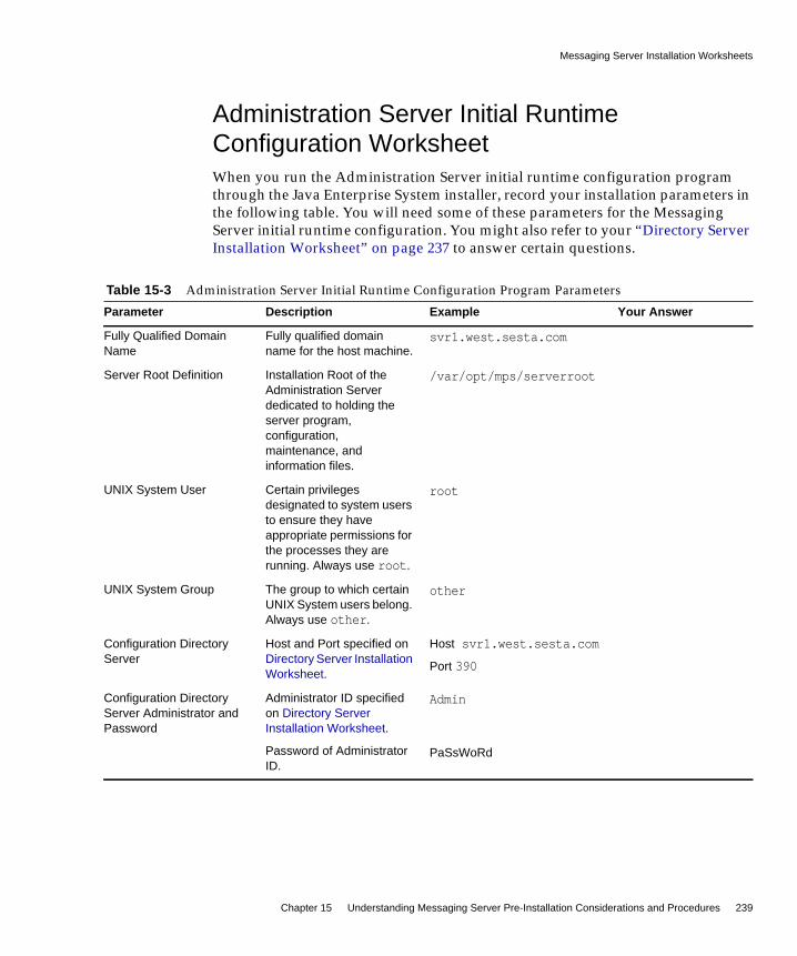
Messaging Server Installation Worksheets
Chapter 15 Understanding Messaging Server Pre-Installation Considerations and Procedures 239
Administration Server Initial RuntimeConfiguration WorksheetWhen you run the Administration Server initial runtime configuration programthrough the Java Enterprise System installer, record your installation parameters inthe following table. You will need some of these parameters for the MessagingServer initial runtime configuration. You might also refer to your “Directory ServerInstallation Worksheet” on page 237 to answer certain questions.
Table 15-3 Administration Server Initial Runtime Configuration Program Parameters
Parameter Description Example Your Answer
Fully Qualified DomainName
Fully qualified domainname for the host machine.
svr1.west.sesta.com
Server Root Definition Installation Root of theAdministration Serverdedicated to holding theserver program,configuration,maintenance, andinformation files.
/var/opt/mps/serverroot
UNIX System User Certain privilegesdesignated to system usersto ensure they haveappropriate permissions forthe processes they arerunning. Always use root.
root
UNIX System Group The group to which certainUNIX System users belong.Always use other.
other
Configuration DirectoryServer
Host and Port specified onDirectory Server InstallationWorksheet.
Host svr1.west.sesta.com
Port 390
Configuration DirectoryServer Administrator andPassword
Administrator ID specifiedon Directory ServerInstallation Worksheet.
Password of AdministratorID.
Admin
PaSsWoRd

Choosing Which Messaging Server Components to Configure
240 Communications Services 6 2005Q1 • Deployment Planning Guide
Choosing Which Messaging Server Componentsto Configure
When you install Messaging Server software, the Java Enterprise System installerinstalls all the Messaging Server packages. You then configure the appropriateMessaging Server component (MTA, Message Store, Messenger Express, MMP) ona Messaging host through the Messaging Server configuration program.
The following table shows which components you need to configure for each typeof Messaging host.
Administration Domain A region of administrativecontrol.
If you have installedMessaging Server andDirectory Server on thesame machine, then youshould choose the sameAdministration Domain onDirectory Server InstallationWorksheet.
System Lab2
Administrative Server Port A unique port numberdedicated to theAdministration Server.
5555
Table 15-4 Which Messaging Server Components to Configure?
Type of Messaging Host Being Configured Needs These Components Selected in theConfigurator Program
MTA Message Transfer Agent
Message Store (back end) Message Transfer Agent, Message Store,Messenger Express
Note: You need to configure the store for anMEM proxy after configuration is done.
Messenger Express (front end only, no store orSMTP function)
Messenger Express, Messaging Multiplexor
Note: If you are only configuring MessengerExpress, you must also select the MessageStore and the MTA, or at least be able to pointto an existing MTA.
Table 15-3 Administration Server Initial Runtime Configuration Program Parameters (Continued)
Parameter Description Example Your Answer

Disabling the sendmail Daemon
Chapter 15 Understanding Messaging Server Pre-Installation Considerations and Procedures 241
Disabling the sendmail DaemonPrior to installing Messaging Server, you should disable the sendmail daemon if itis running. The Dispatcher, under which the Messaging Server SMTP server runs,needs to bind to port 25. If the sendmail daemon is running (on port 25), theDispatcher will not be able to bind to port 25.
➤ To Disable the sendmail Daemon
1. Change to the /etc/init.d directory.
2. Stop the sendmail daemon if it is running.
Message Multiplexor (front end only, no storeor SMTP function)
Messaging Multiplexor
NOTE Configuring the LMTP delivery mechanism requires configurationon both the MTAs and on the back-end stores. See the Sun JavaSystem Messaging Server Administration Guide for instructions onconfiguring LMTP:
http://docs.sun.com/doc/819-0105
cd /etc/init.d
./sendmail stop
Table 15-4 Which Messaging Server Components to Configure? (Continued)
Type of Messaging Host Being Configured Needs These Components Selected in theConfigurator Program
Disabling the sendmail Daemon
242 Communications Services 6 2005Q1 • Deployment Planning Guide
3. Modify /etc/default/sendmail by adding MODE="".
If the sendmail file does not exist, create the file and then add MODE="".
If a user accidentally runs sendmail start, or if a patch restarts sendmail, thenadding this modification prevents sendmail from starting up in daemon mode.
NOTE In some cases (especially on Solaris 10), even after you run the/etc/init.d/sendmail stop command, sendmail is autorestarted.In this case, use the following command to stop the sendmailprocess:
svcadmin disable network/smtp:sendmail

Part III
Deploying Calendar Server
Chapter 16, “Introduction to Calendar Server Software”
Chapter 17, “Developing a Calendar Server Architecture”
Chapter 18, “Planning Calendar Server Security”
Chapter 19, “Planning Calendar Server Services”
Chapter 20, “Understanding Calendar Server Pre-InstallationConsiderations”

245
Chapter 16
Introduction to Calendar ServerSoftware
This chapter provides an overview of Sun Java System Calendar Server, thebusiness reasoning behind deploying Calendar Server, and the deploymentprocess itself.
This chapter contains the following sections:
• Calendar Server Overview
• Designing Your Calendar Server Deployment
Calendar Server OverviewSun Java System Calendar Server (formerly Sun™ ONE Calendar Server) is ahigh-performance, Internet standards-based calendar server designed with thescalability to meet the needs of customers ranging from medium- and large-sizedenterprises to even the largest telecommunication and Internet service providers.Through a native Web browser interface or connectors to other calendar clients,including Microsoft Outlook, Calendar Server provides group scheduling andpersonal calendaring to consumers at home or at work, while enabling them toshare calendar information with others over the Internet. The user interface (UI)can be customized to include Web links for e-commerce, banner ads, logo, or brandof the calendar server customer, and more.

Calendar Server Overview
246 Communications Services 6 2005Q1 • Deployment Planning Guide
Calendar Server provides one of the industry’s most open, interoperable, andhigh-performance time and resource management solutions. Through itsscalability, performance, and reliability, it provides the features you require at alower total cost of ownership than alternative solutions. Native support foriCalendar standards enables users to schedule events in a format that is easilyshared across the Internet. Calendar Server employs standards and protocols suchas:
• Internet Calendaring (iCalendar)
• iCalendar Transport-Independent Interoperability Protocol (iTIP)
• iCalendar Message-based Interoperability Protocol (iMIP)
• eXtensible Markup Language (XML)
• Lightweight Directory Access Protocol (LDAP)
• HyperText Transport Protocol (HTTP)
The Calendar Server architecture is flexible, extensible, and scalable both vertically(by increasing the number of CPUs per system) and horizontally (by introducingadditional servers into the network). As a result, Calendar Server can be thought ofas a system of servers that can be configured to fit a variety of needs. It can remainin isolation as a standalone calendar server, or it can be configured with manyinstances, having the various services duplicated or split between them.
Calendar Server makes use of plugins to obtain external services. Calendar Serveralso supports both LDAP- and identity-based deployments, and integrates withSun Java System Access Manager (formerly Identity Server), Sun Java SystemPortal Server (formerly Sun ONE Portal Server), and Sun Java System InstantMessaging (formerly Sun ONE Instant Messaging) to provide additionalfunctionality.
Calendar Server provides the following benefits:
• Web-based group scheduling, free-busy lookup, and corporate directorylookup
• Web-based resource scheduling for conference rooms, projectors, and otherresources
• XML-based customization (color, login, user interface, logo, branding, and soon)
• Support for standards-based event and calendar data feeds published in XMLor iCalendar formats, which improves communication and can offer newrevenue opportunities through commerce links and banner ads

Calendar Server Overview
Chapter 16 Introduction to Calendar Server Software 247
• Native LDAP support, with an API for other directory services
• Connectors to additional calendar clients, such as Microsoft Outlook, enablingthese clients to perform scheduling on Calendar Server
• Support for hosted domains
• Simplified system management, online backup and restore, and entiredatabase backup and restore
• Support for multiple calendars, such as work, family, friends, and more
• Support for public and private calendars, as well as public, private, andconfidential individual events
• Support for layered calendar views, which enables users to combine two ormore calendars into a single view, providing improved communication andproductivity
• Automatic e-mail notification of appointments, invitations, and reminders sentto selected recipients; integrates with Sun Java System Instant Messaging toprovide automatic pop-up reminders
• Support for multiple owners of each calendar, to facilitate communication andproductivity with project teams and community groups
• Ability to delegate calendar ownership to others who may act on behalf of theprimary owner
• Daily, weekly, monthly, yearly, and comparison views
• Supports hundreds of thousands of users through a scalable, networked,server-to-server, client- server architecture
• Supports Secure Sockets Layer (SSL) encryption, LDAP authentication,authentication plugins, and identity-enabled single sign-on (SSO) throughAccess Manager
For more information on Calendar Server concepts, see the Sun Java SystemCalendar Server Administration Guide:
http://docs.sun.com/doc/819-0024

Designing Your Calendar Server Deployment
248 Communications Services 6 2005Q1 • Deployment Planning Guide
Designing Your Calendar Server DeploymentThe deployment process consists of the following general phases, referred to as theSolution Life Cycle:
• Analyzing business requirements
• Analyzing technical requirements
• Designing the logical architecture
• Designing the deployment architecture
• Implementing the deployment
• Operating the deployment
The deployment phases are not rigid: the deployment process is iterative in nature.
For detailed information on the deployment process for Calendar Server, and otherJava Enterprise System components, see the Sun Java System Deployment PlanningGuide:
http://docs.sun.com/doc/819-0058
Objectives of Your Calendar Server DeploymentBefore you begin your Calendar Server deployment planning, a good question toask is:
Why is my organization deploying Calendar Server?
Several reasons to consider are:
• Cost savings. The total cost of ownership per user is lower than using othercalendar products on the market.
• Increased productivity. Your calendar users can manage their events and tasksas well as schedule meetings and appointments with others in theorganization. Your users can also manage calendar groups and resources suchas meeting rooms and equipment. They can also synchronize their calendarswith mobile devices (PDAs) and Microsoft Outlook.
• Improved scalability and availability. Calendar Server scales bothhorizontally and vertically. If your organization grows, you can easily upgradeyour configuration by upgrading a server or add more servers.

Designing Your Calendar Server Deployment
Chapter 16 Introduction to Calendar Server Software 249
• Improved security. If you deploy Calendar Server on a Solaris system, yourorganization can avoid many viruses and other security threats that arecommon in Windows environments.
• High availability (HA) configuration. Integration with e Sun Cluster softwareenables you to configure Calendar Server as a highly available service. If youexperience a software or hardware failure, Calendar Server fails over to asecondary server.
Calendar Server Deployment TeamDeploying Calendar Server usually involves a number of people, each withdifferent roles and responsibilities. In a small organization, one person mightperform several roles. Some of the roles to consider are:
• Program Manager oversees the overall Calendar Server deployment and isresponsible for its success or failure.
• Calendar Server Administrator performs day-to-day administrative tasks tomanage Calendar Server and might also be responsible for installing andupgrading Calendar Server.
• Performance Engineer tests and monitors the Calendar Server performance forthe trial and production deployments to see if the deployment criteria is met.
• Development Engineering writes Calendar Server applications or plugins, orcustomizes the Calendar Server user interface (UI), if required.
• Documentation Specialist writes any customized documentation foradministrators and end users.
• Education/Training develops training classes and material.
• Support Specialists, who support both the trial and production deployments.
Calendar Server End UsersEnd users can connect to Calendar Server by using the Calendar Express Webclient, Communications Express web client, or Sun Java System Connector forMicrosoft Outlook.
Questions about end users at your site include:
• How many total Calendar Server end users will your site have?
Designing Your Calendar Server Deployment
250 Communications Services 6 2005Q1 • Deployment Planning Guide
• How will your end users connect to Calendar Server? Calendar Express?Communications Express? Microsoft Outlook? A combination of clients?
• How many geographic locations are involved? Are your end users all in thesame or different time zones?
• Will your end users log into Calendar Server at the same time each day?
• How many active end users will your deployment have during peak use?
• How fast will your end user base grow?
• What are your specific performance requirements for Calendar Server endusers?
• What are your single sign-on (SSO) requirements?
• Are any of your users migrating from Netscape™ Calendar 4.x?
• Are your end users planning to use Sun ONE Synchronization?
• Are you planning to customize the Calendar Server UI for your end users?
• Does your site plan to use a proxy server?
• Does your site plan to use load balancing?
Expected Calendar Server End UserPerformanceWhat are your specific performance requirements for your end users? For example:
• What end user response times are acceptable?
• Can you tolerate a possible degradation in performance during peak loadtimes?
What configuration do you plan to use for your deployment? Calendar Serverconfiguration scenarios include:
• Single Calendar Server instance
• Single front-end server with single back-end database server
• Multiple front-end servers with multiple back-end database servers usingLDAP CLD plugin
• Multiple front-end/back-end servers using LDAP CLD plugin

Designing Your Calendar Server Deployment
Chapter 16 Introduction to Calendar Server Software 251
• High Availability (HA) configuration
If you plan to configure multiple front-end servers, how do you plan to distributeyour end users?
If you plan to configure multiple back-end database servers, how do you plan todistribute your database? For example, you could distribute serversgeographically.
What plans to you have for growth? For both front-end and back-end servers?

Designing Your Calendar Server Deployment
252 Communications Services 6 2005Q1 • Deployment Planning Guide

253
Chapter 17
Developing a Calendar ServerArchitecture
This chapter describes three basic Calendar Server deployment architectures,which can vary depending on your site’s specific requirements.
This chapter contains the following sections:
• Single-Server Calendar Server Architecture
• Two-tiered Calendar Server Architecture
• Two-tiered, Multiple Server Calendar Server Architecture
Single-Server Calendar Server ArchitectureFigure 17-1 on page 254 shows a single-server architecture. In this deployment, allCalendar Server services (processes) run on the same server, either in the sameCPU (processor) or across multiple CPUs. The Directory Server and AccessManager processes can run on the same server or on different servers.

Single-Server Calendar Server Architecture
254 Communications Services 6 2005Q1 • Deployment Planning Guide
Figure 17-1 Single-Server Calendar Server Architecture
A Calendar Server instance on a single server includes the following services:
• Administration service (csadmind process) provides support for administrationfunctions such as commands to start or stop Calendar Server, create or deletecalendar users or resources, or fetch and store calendars.
• HTTP service (cshttpd process) handles incoming SHTML and WCAPrequests.
• Event Notification Service (enpd) acts as the broker for event and alarmnotifications.
• Backup service (csstored) implements automatic backups, both archivalbackups and hot backups.
For a description of Calendar Server services, see the Sun Java System CalendarServer Administration Guide:
http://docs.sun.com/819-0024
The Database Wire Protocol (DWP) service (csdwpd process), which providesnetworking capability when the calendar database is on another server, is notrequired for a minimal configuration because the database is on the same server.
Directorydatabase
End Users
CalendarServer
SHTML and WCAP Requests
DirectoryServer
AccessManager
Calendardatabase
cshttpd

Single-Server Calendar Server Architecture
Chapter 17 Developing a Calendar Server Architecture 255
Calendar Server requires a directory server to authenticate users and to store userpreferences. Usually, the directory server is an LDAP directory server, such as SunJava System Directory Server. However, if you prefer, you can use the CalendarServer API (CSAPI) to write a plugin to use a non-LDAP directory server. This APIis described in the Sun Java System Calendar Server Developer’s Guide:
http://docs.sun.com/doc/819-0025
The directory server can run on the same server where Calendar Server is runningor on a remote server.
Sun Java System Access Manager (release 2003Q4 (6.1) or later) provides thefollowing functionality:
• Communications Services Delegated Administrator utility. Use the CLIutility (commadmin) to provision and manage hosted (virtual) domains, users,groups, organizations, resources, and roles for Sun Java Systemcommunications servers, including Calendar Server.
For information about the Communications Services Delegated Administratorutility, see the Sun Java System Communications Services Delegated AdministratorGuide:
http://docs.sun.com/doc/819-0114
• Single Sign-on (SSO). You can implement SSO for Sun Java Enterprise Systemservers, including Calendar Server and Messaging Server, using AccessManager, or through trusted circle technology. Access Manager serves as theSSO gateway for Java Enterprise System servers. Users log in to AccessManager and then can access other the servers, as long as all servers areconfigured properly for SSO.
• Sun Java System LDAP Schema 2. Access Manager (release 2003Q4 or later) isrequired if you want to use this version of the schema.
For more information on these topics, see the Sun Java System Calendar ServerAdministration Guide:
http://docs.sun.com/819-0024
Access Manager can run on the same server where Calendar Server is running oron a remote server.
End users connect to Calendar Server from client machines by using one of twoWeb user interfaces (UIs), either Sun Java System Calendar Express, or Sun JavaSystem Communications Express. For information using these interfaces, see therespective interface’s online Help.

Two-tiered Calendar Server Architecture
256 Communications Services 6 2005Q1 • Deployment Planning Guide
Two-tiered Calendar Server ArchitectureCalendar Server supports scalability by distributing a configuration over multiplefront-end and back-end servers. On each server, Calendar Server services can alsobe distributed across multiple CPUs.
In a two-tiered architecture, sometimes referred to as network front-end/databaseback-end configuration (shown in the following figure), users log in to a front-endserver and connect to a back-end server using the Database Wire Protocol (DWP)service (csdwpd process). The calendar database is connected only to the back-endservers.
Figure 17-2 Two-tiered Calendar Server Architecture
End Users End Users
Load Balancers
Front-end servers
cshttpd
cshttpd
cshttpd
Directorydatabase
DirectoryServer
AccessManager
Calendardatabase
Calendardatabase
Calendardatabase
Back-end servers
csdwpd
csdwpd
csdwpd
Database Wire Protocol (DWP)

Two-tiered Calendar Server Architecture
Chapter 17 Developing a Calendar Server Architecture 257
Calendar Server processes run on both the front-end and back-end servers asfollows:
• Users are directed by load balancers to a front-end server, where they log in.Each front-end server requires these services:
❍ Administration Service (csadmind process)
❍ HTTP Service (cshttpd process)
• Each back-end server is connected to a calendar database, so each back-endserver requires these services:
❍ Administration Service (csadmind process)
❍ Backup service (csstored)
❍ Event Notification Service (enpd and csnotifyd processes)
❍ Database Wire Protocol (DWP) Service (csdwpd process) to providenetworking capability to the front-end servers for the calendar database
In this configuration, users do not log in to the back-end servers, so the HTTPservice (cshttpd process) is not required.
For a description of Calendar Server services, see the Sun Java System CalendarServer Administration Guide:
http://docs.sun.com/819-0024
A scalable Calendar Server configuration requires a directory server toauthenticate users and to store user preferences.
You can use Access Manager (release 6.1 (release 6 2003Q4) or later) to implementSingle Sign-on (SSO), to use Sun Java Enterprise System LDAP Schema 2, or toprovision and manage hosted (virtual) domains, users, groups, organizations,resources, and roles.
End users connect to Calendar Server from client machines by using one of twoWeb user interfaces (UIs), either Sun Java System Calendar Express, or Sun JavaSystem Communications Express. For information using these interfaces, see therespective interface’s online Help.

Two-tiered, Multiple Server Calendar Server Architecture
258 Communications Services 6 2005Q1 • Deployment Planning Guide
Two-tiered, Multiple Server Calendar ServerArchitecture
In a two-tiered Calendar Server architecture with multiple front-end and back-endservers (shown in Figure 17-3 on page 259), users log in to a specific server, andeach server is connected to a calendar database. This configuration enablescalendars to be geographically distributed, with each calendar residing on theserver where its owner logs in to Calendar Server.

Two-tiered, Multiple Server Calendar Server Architecture
Chapter 17 Developing a Calendar Server Architecture 259
Figure 17-3 Two-tiered, Multiple Server Calendar Server Architecture
In this architecture, each server functions as both a front end and back end, andrequires all Calendar Server services: Administration Service (csadmind process),HTTP Service (cshttpd process), Event Notification Service (enpd and csnotifydprocesses), and Database Wire Protocol (DWP) Service (csdwpd process).
Directorydatabase
DirectoryServer
AccessManager
Front-end/Back-end server-1
Calendardatabase
End Users
Front-end/Back-end server-2
Calendardatabase
End Users
Front-end/Back-end server-3
Calendardatabase
End Users
Two-tiered, Multiple Server Calendar Server Architecture
260 Communications Services 6 2005Q1 • Deployment Planning Guide
For a description of Calendar Server services, see the Sun Java System CalendarServer Administration Guide:
http://docs.sun.com/doc/819-0024
A multiple front-end/back-end server deployment requires a directory server toauthenticate users and to store user preferences.
You can use Access Manager (release 6.1 (release 6 2003Q4) or later) to implementSingle Sign-on (SSO), to use Sun Java Enterprise System LDAP Schema 2, or toprovision and manage hosted (virtual) domains, users, groups, organizations,resources, and roles.
End users connect to Calendar Server from client machines by using one of twoWeb user interfaces (UIs), either Sun Java System Calendar Express, or Sun JavaSystem Communications Express. For information using these interfaces, see therespective interface’s online Help.
NOTE In this architecture, you could also separate the front end servicesfrom the back end services onto separate machines, and use theLDAP Calendar Lookup Database (CLD) to determine which backend a front end needs to get data from. For more information, seethe Sun Java System Calendar Server Administration Guide.

261
Chapter 18
Planning Calendar Server Security
This chapter describes how to plan for and protect the various components of yourCalendar Server deployment.
This chapter contains the following sections:
• Calendar Server Security Overview
• Planning Calendar User Authentication
Calendar Server Security OverviewSecurity plays a key role in the day-to-day operations of today’s businesses.Breaches in security can not only compromise trade secrets, but can also result indowntime, data corruption, and increased operation costs. Calendar Serverprovides a number of security levels to protect users against eavesdropping,unsanctioned usage, or external attack. The basic level of security is throughauthentication. Calendar Server uses LDAP authentication by default, but alsosupports the use of an authentication plugin for cases where an alternate means ofauthentication is desired. Furthermore, integration with Access Manager enablesCalendar Server to take advantage of its single sign-on capability.
Security involves not only ensuring the integrity of users. It also means ensuringthe confidentiality of data. To this end, Calendar Server supports the use of SSLencryption for login, or both login and data. In other words, only the login may beencrypted, or the entire session including the login may be encrypted, from theWeb client to the server.
Integration with Secure Remote Access also provides SSL encryption, but througha proxy gateway. In addition, integration with the portal gateway provides a URLrewriting capability to further insulate Calendar Server from external entities.Calendar Server can be deployed with the portal gateway such that there is no

Calendar Server Security Overview
262 Communications Services 6 2005Q1 • Deployment Planning Guide
direct connection to the Calendar Server without going through the gateway. Inthis case, every URL is rewritten, thus obfuscating the true URL of the CalendarServer. Even though a user is authenticated, that does not mean that the usershould have access to other calendar users’ data.
Within a calendar domain exist other layers of security to prevent authenticatedusers from unauthorized access to other authenticated users’ calendar data. Onesecurity measure is through the Calendar Server access control entries. Accesscontrol enables calendar users to specify who can see their calendars, who canschedule events into their calendars, who can modify their calendars, and who candelete events from their calendars. Access control also enables users to select whocan act on their behalf to respond to invitations, schedule or modify events, anddelete events. Finally, access control can be used to span domains of users, thuspreventing (or enabling) users in one domain from scheduling events with users ofanother domain.
In addition to access control, Calendar Server provides an additional level ofsecurity at the database protocol level for deployments that separate the calendarfront end from the database back end. This level of security is referred to asDatabase Wire Protocol (DWP) authentication, and utilizes a user name/passwordpair to authenticate a DWP connection. The user name/password pairs on both thefront end and database back end must be identical for a DWP connection to beauthenticated.
Monitoring Your Security StrategyMonitoring your server is an important part of your security strategy. To identifyattacks on your system, monitor message queue size, CPU utilization, diskavailability, and network utilization. Unusual growth in the message queue size orreduced server response time can identify some of these attacks. Also, investigateunusual system load patterns and unusual connections. Review logs on a dailybasis for any unusual activity.
Planning Calendar User Authentication
Chapter 18 Planning Calendar Server Security 263
Planning Calendar User AuthenticationUser authentication enables your users to log in through their calendar clients toretrieve their calendar information. Methods for user authentication include:
• Plain Text and Encrypted Password Login
• Certificate-based Authentication with Secure Sockets Layer (SSL)
Plain Text and Encrypted Password LoginUser IDs and passwords are stored in your LDAP directory. Password securitycriteria, such as minimum length, are determined by directory policyrequirements. Password security criteria is not part of Calendar Serveradministration. To understand directory server password policies, see the Sun JavaSystem Directory Server Deployment Planning Guide:
http://docs.sun.com/doc/817-7607
Both plain text and encrypted password login can be used.
Certificate-based Authentication with SecureSockets Layer (SSL)Calendar Server uses the SSL protocol for encrypted communications and forcertificate-based authentication of clients and servers. This section describescertificate-based SSL authentication.
SSL is based on the concepts of public-key cryptography. Although TLS (TransportLayer Security) is functionally a superset of SSL, the names are usedinterchangeably.
At a high-level, a server which supports SSL needs to have a certificate, a publickey, a private key, certificate, key, and security databases. This helps assuremessage authentication, privacy, and integrity.
To authenticate with SSL, the calendar client establishes an SSL session with theserver and submits the user’s certificate to the server. The server then evaluates ifthe submitted certificate is genuine. If the certificate is validated, the user isconsidered authenticated.
Planning Calendar User Authentication
264 Communications Services 6 2005Q1 • Deployment Planning Guide
If you use SSL for authentication, you need to obtain a server certificate for yourCalendar Server. The certificate identifies your server to clients and to otherservers. Your server can have more than one server certificate with which itidentifies itself. Your server can also have any number of certificates of trustedCertification Authorities (CAs) that it uses for client authentication.
For more information on SSL, see the Sun Java System Calendar ServerAdministration Guide:
http://docs.sun.com/doc/819-0024

265
Chapter 19
Planning Calendar Server Services
This chapter describes the planning information for Calendar Server services.
This chapter contains the following sections:
• Planning for Calendar Server Front-end and Back-end Services
• Planning for the Calendar Server LDAP Data Cache
Planning for Calendar Server Front-end andBack-end Services
Calendar Server consists of six major services:
• HTTP Service (cshttpd) listens for HTTP requests. It receives user requests andreturns data to the caller.
• Administration Service (csadmind) is required for each instance of CalendarServer. It provides a single point of authentication and administration for theCalendar Servers and provides most of the administration tools.
• Notification Service (csnotify) sends notifications of events and to-dos usingeither email or the Event Notification Service.
• Event Notification Service (enpd) acts as the broker for event alarms.
• Distributed Database Service (csdwpd) links multiple database servers togetherwithin the same Calendar Server system to form a distributed calendar store.

Planning for Calendar Server Front-end and Back-end Services
266 Communications Services 6 2005Q1 • Deployment Planning Guide
• Backup Service (csstored) implements automatic backups, both archivalbackups and hot backups. The first backup is a snapshot with log files, thesecond is a snapshot with log files applied. This service is automatically startedwhen you run the start-cal command. However, it is not enabled atinstallation time, so you must configure it to function. If left unconfigured,Backup Service sends out a message to the administrator every 24 hours, withthe notification that the service is not configured.
In a scalable Calendar Server deployment, you would deploy front-end systems inconjunction with a back-end server. The front-end systems would contain oneinstance of the cshttpd daemon per processor and a single Administration Service.A back-end server would contain an instance of Notification Service, EventNotification Service, Distributed Database Service and Administration Service.
Authentication and XML /XSLT transformation are two Calendar Service activitiesthat generate heavy load. Additional CPUs can be added to meet quality of servicerequirements. In a scalable environment, these heavy load activities take place onthe front-end system(s), permitting more CPUs to be added to individual front-endsystems, or more front-end systems to be added, to meet quality of servicerequirements.
Calendar back-end services usually require half the number of CPUs sized for theCalendar front-end services. To support quality of service by the Calendarfront-end system, the Calendar back-end system should use around two-thirds ofthe front-end CPUs.
You will want to consider early on in a deployment separating the CalendarService into front-end and back-end services. Assign a separate host name for thefront-end services and back-end services so that when it comes time to separate thefunctionality onto different hosts, the changes are essentially internal and do notrequire users to change their methods of operation.
NOTE The preceding paragraph is not applicable if the CommunicationsExpress Calendar client is used for calendar access.Communications Express uses the WCAP protocol to accessCalendar Server data and therefore the Calendar Serverinfrastructure is not doing the XML/XSLT translations. See Part V,“Deploying Communications Express” for information ondeploying Communications Express.

Planning for Calendar Server Front-end and Back-end Services
Chapter 19 Planning Calendar Server Services 267
The Calendar Server HTTP process that is typically a component of the front-endservices is a dominant user of CPU time. Account for peak calendar usage toprovide enough front-end processing power to accommodate the expected peakHTTP sessions. Typically, you would make the Calendar Server front end moreavailable through redundancy, that is, by deploying multiple front-end hosts. Asthe front-end systems do not maintain any persistent calendar data, they are notgood candidates for HA solutions like Sun Cluster. Moreover, the additionalhardware and administrative overhead of such solutions make deploying HA forCalendar Server front ends both expensive and time-consuming.
A good choice of hardware for the Calendar Server front ends is a single or dualprocessor server. You would deploy one instance of the Calendar Server cshttpddaemon per processor. Such a deployment affords a cost-effective solution,enabling you to start with some level of initial client concurrency capability andadd client session capacity as you discover peak usage levels on your existingconfiguration.
When you deploy multiple front ends, a load balancer (with sticky/persistentconnections) is necessary to distribute the load across the front-end services.
The Calendar Server back-end services are well balanced in resource consumptionand show no evidence of bottleneck formation either in CPU or I/O (disk ornetwork). Thus, a good choice of hardware for the back end would be a SPARCserver with a single striped volume. Such a machine presents considerable capacityfor large-peak calendar loads.
If your requirements include high availability, it makes sense to deploy theCalendar Server back end with Sun Cluster, as the back end does contain persistentdata.
NOTE The only configuration for Calendar front ends that might warrant atrue HA solution is where you have deployed the Calendar frontend on the same host that contains a Messaging Server MTA. Evenin this configuration, however, the overhead of such a solutionshould be carefully weighed against the slight benefit.

Planning for the Calendar Server LDAP Data Cache
268 Communications Services 6 2005Q1 • Deployment Planning Guide
Planning for the Calendar Server LDAP DataCache
The LDAP data cache option ensures that LDAP data is available immediately afterit has been committed. In some configurations of the LDAP directory server anupdate might need to be referred to a (remote) master server from which theupdate is then replicated down to the local LDAP directory. These kinds ofconfigurations can induce a delay in the availability of committed data on the localLDAP server.
For example, if your site has deployed a master/slave LDAP configuration whereCalendar Server accesses the master LDAP directory through a slave LDAPdirectory server, which in turn introduces a delay in the availability of committedLDAP data, the LDAP data cache can ensure that your Calendar Server clientshave accurate LDAP data.
This section covers the following topics:
• Considerations for Using the LDAP Data Cache
• Master/Slave LDAP Configuration
• Resolving the Master-Slave Delay Problem
• Configuring the LDAP Data Cache
NOTE In a configuration with both front-end and back-end CalenderServer hosts, all hosts must be running:
• The same operating system environment and version; that is,you cannot have a mixture of systems running Solaris SPARC,Solaris x86, Linux Red Hat, and so forth.
• The same releases of Calendar Server, including patch or hotfixreleases.

Planning for the Calendar Server LDAP Data Cache
Chapter 19 Planning Calendar Server Services 269
Considerations for Using the LDAP Data CacheUse these guidelines to determine if your site should configure the LDAP datacache:
• If Calendar Server at your site accesses your master (or root) LDAP directoryserver directly with no delays in the availability of committed LDAP data, youdon’t need to configure the LDAP data cache. Make sure that thelocal.ldap.cache.enable parameter is set to “no” (which is the default).
• If your site has deployed a Master/Slave LDAP Configuration where CalendarServer accesses the master LDAP directory through a slave LDAP directoryserver, which in turn introduces a delay in the availability of committed LDAPdata, configure the LDAP data cache to ensure that your end users have themost recent data.
Master/Slave LDAP ConfigurationA Master/Slave LDAP configuration includes a master (root) directory server andone or more slave (consumer or replica) directory servers. Calendar Server canaccess the master LDAP directory server either directly or through a slavedirectory server:
• If Calendar Server accesses the master LDAP directory server directly, theLDAP should be accurate, and you do not need to configure the LDAP datacache.
• If Calendar Server accesses the master LDAP directory server through a slavedirectory server, LDAP data changes are usually written transparently via anLDAP referral to the master directory server, which in turn replicates the databack to each slave directory server.
In this second type of configuration, problems with inaccurate LDAP data canoccur because of the delay in the availability of committed LDAP data to the slavedirectory servers.
For example, Calendar Server commits an LDAP data change, but the new data isnot available for a specific amount of time because of the delay in the masterdirectory server updating each slave directory server. A subsequent CalendarServer client operation uses the old LDAP data and presents an out-of-date view.
If the delay in updating the slave directory servers is short (only a few seconds),clients might not experience a problem. However, if the delay is longer (minutes orhours), clients will display inaccurate LDAP data for the length of the delay.

Planning for the Calendar Server LDAP Data Cache
270 Communications Services 6 2005Q1 • Deployment Planning Guide
The following table lists the LDAP attributes that are affected by a delay in amaster/slave LDAP server configuration where Calendar Server accesses themaster LDAP directory server through a slave LDAP directory server.
To ensure that your end uses have the most recent LDAP data, configure the LDAPdata cache as described in the following section, “Resolving the Master-Slave DelayProblem.”
Resolving the Master-Slave Delay ProblemThe LDAP data cache resolves the master/slave LDAP configuration problem byproviding Calendar Server clients with the most recent LDAP data, even when themaster directory server has not updated each slave directory server.
If the LDAP data cache is enabled, Calendar Server writes committed LDAP datato the cache database (ldapcache.db file). By default, the LDAP cache database islocated in the cal_svr_base/var/opt/SUNWics5/csdb/ldap_cache directory, but you canconfigure a different location if you prefer.
When a client makes a change to the LDAP data for a single user, Calendar Serverwrites the revised data to the LDAP cache database (as well as to the slavedirectory server). A subsequent client operation retrieves the LDAP data from thecache database. This data retrieval applies to the following operations for a singleuser:
• User’s attributes at login
• User’s options (such as color scheme or time zone)
• User’s calendar groups
Table 19-1 Calendar Server LDAP Attributes Affected by Delays
Operation LDAP Attributes Affected
Auto provisioning icsCalendar, icsSubscribed, icsCalendarOwned, icsDWPHost
Calendar groups icsSet
Calendar creation icsCalendarOwned, icsSubscribed
Calendar subscription icsSubscribed
User options icsExtendedUserPrefs, icsFirstDay, icsTimeZone,icsFreeBusy
Calendar searches icsCalendarOwned

Planning for the Calendar Server LDAP Data Cache
Chapter 19 Planning Calendar Server Services 271
• User’s subscribed list of calendars
Thus, the LDAP data cache database provides for:
• Data consistency across processes on a single system—The database isavailable to all Calendar Server processes on a multiprocessor system.
• Data persistence across user sessions—The database is permanent and doesnot require refreshing. You can configure the time to live (TTL) for an LDAPdata cache entry and the interval between each database cleanup.
Limitations to the LDAP Data CacheThe LDAP data cache does not provide for:
• Reading the cache for searches where a list of entries is expected, for example,searching for attendees for a meeting. This type of search is subject to anyLDAP delay. For instance, a newly created calendar will not appear in acalendar search if the LDAP search option is active and the search is performedwithin the delay period following the creation of a new calendar.
• Reading and writing of the cache across multiple front-end servers. Eachfront-end server has its own cache, which is not aware of data in other caches.
• The capability to handle a user who doesn’t always log into the same server.Such a user will generate different LDAP data in the cache on each server.
Configuring the LDAP Data CacheConfigure the LDAP data cache by setting the appropriate parameters in theics.conf file. See the Sun Java System Calendar Server Administration Guide for moreinformation:
http://docs.sun.com/doc/819-0024
CAUTION If Calendar Server or the server where Calendar Server is running isnot properly shut down, manually delete all files in the ldap_cachedirectory to avoid any database corruption that might causeproblems during a subsequent restart.

Planning for the Calendar Server LDAP Data Cache
272 Communications Services 6 2005Q1 • Deployment Planning Guide

273
Chapter 20
Understanding Calendar ServerPre-Installation Considerations
This chapter describes considerations you need to think about before installingCalendar Server.
This chapter contains the following sections:
• Calendar Server Installation Considerations
• Planning for Calendar Server Administrators
• Planning for Calendar Server Hosted Domains
• Post-Installation Calendar Server Configuration
Calendar Server Installation ConsiderationsThe installation and configuration of Calendar Server has significantly changedfrom earlier Calendar Server releases (pre-2003Q4 versions). There is no longer astandalone installer for Calendar Server.
If you do not already have Calendar Server installed, you must use the Sun JavaEnterprise System installer to get the 2005Q1 version. With this installer, you canalso install other Sun Java System component products and packages. Forinformation about the Java Enterprise System installer, refer to the Sun JavaEnterprise System 2005Q1 Installation Guide:
http://docs.sun.com/doc/819-0056

Calendar Server Installation Considerations
274 Communications Services 6 2005Q1 • Deployment Planning Guide
If you want to upgrade from Calendar Server 6 2003Q4 to Calendar Server 62005Q1, the upgrade process is described in “Upgrading from Java EnterpriseSystem 2003Q4” in the Sun Java Enterprise System 2005Q1 Upgrade and MigrationGuide:
http://docs.sun.com/819-0062
For information about migrating from older versions of Calendar Server, upthrough version 5.x, see the Migrations Utility chapter in the Sun Java SystemsCalendar Server Administration Guide (covers up to version 5.x):
http://docs.sun.com/doc/819-0024
For migrating from versions later than 5.x, contact your Sun supportrepresentative.
Which Calendar Server Components toConfigure?When you install Calendar Server software, the Java Enterprise System installerinstalls all the Calendar Server packages. You then configure the appropriateCalendar Server component on a Calendar host through the Calendar Serverconfigurator program.
The following table shows which components you need to configure for each typeof Calendar host.
The Distributed Database Service (csdwpd) is required only on back-end servers,that is, a server that has a calendar database, but does not provide user accessservices (cshttpd). It is not required on front-end servers that do not have acalendar database. The csdwpd service enables you to link front-end and back-endservers within the same Calendar Server configuration to form a distributedcalendar store.
Table 20-1 Which Calendar Server Components to Configure?
Type of Calendar Host Being Configured Needs These Components Selected in theConfigurator Program
Front end HTTP service(s) and Administration service
Back end Notification Service, Event Notification Service,Distributed Database Service andAdministration Service
Planning for Calendar Server Administrators
Chapter 20 Understanding Calendar Server Pre-Installation Considerations 275
Planning for Calendar Server AdministratorsAdministrators for Calendar Server include:
• Calendar Server Administrator (calmaster)
• Calendar Server User and Group
• Superuser (root)
Calendar Server Administrator (calmaster)The Calendar Server administrator is a specific user name with its associatedpassword that can manage Calendar Server. For example, a Calendar Serveradministrator can start and stop Calendar Server services, add and delete users,create and delete calendars, and so on. This user has administrator privileges forCalendar Server but not necessarily for the directory server.
The default user ID for the Calendar Server administrator is calmaster, but youcan specify a different user during Calendar Server configuration, if you prefer.After installation you can also specify a different user in theservice.admin.calmaster.userid parameter in the ics.conf file.
The user ID you specify for the Calendar Server administrator must be a valid useraccount in your directory server. If the Calendar Server administrator user accountdoes not exist in the directory server during configuration, the configurationprogram can create it for you.
See the Sun Java System Calendar Serve Administration Guide for the complete list ofCalendar Server administrator configuration parameters in the ics.conf file:
http://docs.sun.com/819-0024
Calendar Server User and GroupOn Solaris systems, these special accounts are the user ID and group ID underwhich Calendar Server runs. Use the default values, icsuser and icsgroup, whichare automatically created by the configuration program, if they do not exist. If youprefer, however, you can specify values other than icsuser and icsgroup whenyou run the Calendar Server configuration program. These values are stored in thelocal.serveruid and local.servergid parameters, respectively, in theics.conf file.

Planning for Calendar Server Hosted Domains
276 Communications Services 6 2005Q1 • Deployment Planning Guide
Superuser (root)On machines running Solaris software, you must log in as or become superuser(root) to install Calendar Server. You can also run as superuser to manageCalendar Server using the command-line utilities. For some tasks, however, youshould run as icsuser and icsgroup (or the values you have selected) rather thansuperuser to avoid access problems for Calendar Server files.
Planning for Calendar Server Hosted DomainsCalendar Server supports hosted (or virtual) domains. In a hosted domaininstallation, each domain shares the same instance of Calendar Server, whichenables multiple domains to exist on a single server. Each domain defines a namespace within which all users, groups, and resources are unique. Each domain alsohas a set of attributes and preferences that you specifically set.
When installing and configuring hosted domains, use Schema 2 only.
Installing and configuring hosted domains on a server involves these high-levelsteps:
1. Installing and configuring Directory Server
2. Installing and configuring Web Server or Application Server
3. Installing and configuring Access Manager
The Delegated Administrator is installed with Access Manager.
4. Installing Calendar Server
5. Running the comm_dssetup.pl script
For instructions on running this script, see Chapter 2 in the Sun Java SystemCalendar Server Administration Guide:
http://docs.sun.com/doc/819-0024
6. Configuring Communications Services Delegated Administrator
For instructions on configuring and using the Communications ServicesDelegated Administrator utility, see the Sun Java System CommunicationsServices Delegated Administrator Guide:
http://docs.sun.com/doc/819-0114
Post-Installation Calendar Server Configuration
Chapter 20 Understanding Calendar Server Pre-Installation Considerations 277
7. Creating default domain and site administrator (calmaster)
The default domain is created when commadmin is configured, but the domainentry must be modified to add Calendar (or Mail) services. Also, the sitecalendar administrator (calmaster) must be set up. For instructions on how toperform these two tasks, see “Post Configuration Tasks” in the Sun Java SystemCalendar Server Administration Guide.
8. Configuring Calendar Server
For instructions on running the csconfiguratior.sh program, see Chapter 3in the Sun Java System Calendar Server Administration Guide.
9. Setting hosted domain configuration parameters for Calendar Server
For a list of the configuration parameters and their values, see “HostedDomain Configuration Parameters” in the Sun Java System Calendar ServerAdministration Guide.
10. Creating the hosted domains for your site by using the commadmin utility
11. Populating your hosted domains with users and resources by using thecommadmin utility
12. Starting Calendar Server services
For instructions, see the Sun Java System Calendar Server Administration Guide.
Post-Installation Calendar Server ConfigurationAfter you install the Calendar Server software, you must configure it. This step waspreviously performed as part of the installation process, but has now beenseparated out of the installer.
After you install Calendar Server, you must configure Calendar Server as follows:
1. Run the Directory Server Setup script (comm_dssetup.pl) to configure Sun JavaSystem Directory Server.
NOTE Always perform your provisioning for Schema 2 with theCommunications Services Delegated Administrator interface.
Schema 1 provisioning tools do not support hosted domains.

Post-Installation Calendar Server Configuration
278 Communications Services 6 2005Q1 • Deployment Planning Guide
2. Run the Calendar Server configuration program (csconfigurator.sh) toconfigure your site’s specific requirements and to create a new ics.confconfiguration file. For a description of the parameters in the ics.conf file, seethe Sun Java System Calendar Server Administration Guide:
http://docs.sun.com/doc/819-0024
The comm_dssetup.pl script is located in the /opt/SUNWcomds/sbin directory, andthe csconfigurator.sh utility is located in the /opt/SUNWics5/cal/sbin directory.
There are some configuration settings and changes that the Java Enterprise Systeminstaller and Calendar Server configuration utility (csconfigurator.sh) do notmake. You must manually make changes to the following items:
• DWP and CLD Configurations. Edit the ics.conf file so that the CLD cacheoption is enabled. This cache stores the DWP host server information forcalendar users and thus reduces calls to the LDAP directory server.
• Default Time Zone. If your default time zone is not Americas/New York,change it by editing the ics.conf file. You also need to change it in the/opt/SUNWics5/cal/bin/html/default_user_prefs.xml file so that it is insync with the ics.conf file.
• Client-side Rendering. Calendar Server performs client-side rendering bydownloading the XSLT processing to the end user’s browser, which in turnreduces the processing that must be done by Calendar Server. Calendar Serverdownloads the XSLT processing only if the browser is capable of rendering theXSLT processing. In the current release, this applies only to Internet Explorer6.0. Edit the ics.conf file to make this performance improvement to client-siderendering.
• Setting for tmpfs. Edit the tmpfs setting for performance enhancement.
For more information on these changes, see the Sun Java System Calendar ServerAdministration Guide.

Part IV
Deploying Instant Messaging
Chapter 21, “Introduction to Instant Messaging Software”
Chapter 22, “Planning an Instant Messaging Sizing Strategy”
Chapter 23, “Developing an Instant Messaging Architecture”
Chapter 24, “Understanding Instant Messaging Pre-InstallationConsiderations”


281
Chapter 21
Introduction to Instant MessagingSoftware
Instant Messaging enables secure, real-time communication and collaboration,combining presence awareness with instant messaging capabilities such as chat,conferences, alerts, news, polls, and file transfers to create a rich collaborativeenvironment. These features enable one-to-one as well as group collaborationthrough either short-lived communications or persistent venues such as conferencerooms or news channels.
Instant Messaging ensures the integrity of communications through its multipleauthentication mechanisms and Secure Sockets Layer (SSL) connections.Integration with Portal Server and Access Manager brings additional securityfeatures, services-based provisioning access policy, user management, and secureremote access.
This chapter contains the following sections:
• What Is an Instant Messaging Service?
• Instant Messaging Core Product Components
• Components Related to Instant Messaging
• Instant Messaging Supported Standards
• Instant Messaging Software Architecture
• Designing Your Instant Messaging Deployment
What Is an Instant Messaging Service?
282 Communications Services 6 2005Q1 • Deployment Planning Guide
What Is an Instant Messaging Service?At a simplistic level, an instant messaging service:
• Accepts instant messages from external sites
• Determines the user to which the message should be delivered, and routes itaccordingly
• Accepts instant messages from internal hosts
• Determines the destination system to which the message should be delivered,and routes it accordingly
In addition, an instant messaging service can provide real-time conferencing, newsand calendar alerts, and for offline users, email message forwarding.
Of crucial importance to a good instant messaging service is that the serviceprovides for scalability, high availability, reliability, and good performance.
Instant Messaging Core Product ComponentsInstant Messaging contains the following core components:
• Instant Messenger Resources (client). A set of files that makes up the clientprogram for end users to initiate, compose, and reply to messages. Typicallyusers also use the client to participate in conferences. The client is also calledSun Java System Instant Messenger.
• Instant Messaging Server. An electronic message delivery system thatsupports instant message delivery from one system to another system. Theserver serves the presence information to Instant Messenger clients, enablesend users to establish sessions, and enforces policies.
• Instant Messaging Multiplexor. A scalability component that consolidatesmessenger connections. To support large deployments, with thousands ofconcurrent connections, Instant Messaging uses a connection multiplexor toimprove server scalability. This component opens a single connection to theInstant Messaging server. In addition to scalability, you can install themultiplexor outside the firewall while leaving the server inside the firewall toprotect it from unauthorized external access. The Instant Messagingmultiplexor is also referred to as the multiplexor.

Components Related to Instant Messaging
Chapter 21 Introduction to Instant Messaging Software 283
• Access, Communication, and Transfer Protocols. These protocols, such asLDAP, HTTP, TCP/IP, and SMTP, can be found in “Instant MessagingSupported Standards” on page 286.
• Access Manager Instant Messaging Service Definition. Instant Messagingprovides a service definition to Access Manager using the Access ManagerSDK, to provide support for Access Manager managed policies and SSOcapabilities.
• Instant Messaging API. Enables you to create custom Instant Messagingclients.
Components Related to Instant MessagingThe software components discussed in this section work with Instant Messagingserver, but are installed separately. Chapter 23, “Developing an Instant MessagingArchitecture” provides more detailed information that illustrates how theseservers interact with Instant Messaging.
Web Server(Required) For any deployment, you need to install a web server, such as Sun JavaSystem Web Server or Sun Java System Application Server. You can also use anyopen standard web server (for example, Apache). In all cases, the InstantMessenger resources must reside on the web server host.
Instant Messaging requires a web server to serve the Instant Messenger resources.The Instant Messenger resource files include:
• The index.html file, provided by Instant Messenger, or a home page with a linkto invoke Instant Messenger
• Instant Messenger jar files (messenger.jar, imres.jar, imbrand.jar,imdesktop.jar, imnet.jar, and imjni.jar)
• The Instant Messenger Online Help
You must install Instant Messenger resources on the same host where the webserver is installed. In an Access Manager deployment, you can install theseresources on the Access Manager server’s host or on a different web server host. Inmost cases, the resources will be installed on the same host where you installed theInstant Messaging server software. It is possible to locate the Instant Messengerresources on a host other than the Instant Messaging server or multiplexor.

Components Related to Instant Messaging
284 Communications Services 6 2005Q1 • Deployment Planning Guide
LDAP Server(Required) Instant Messaging uses an LDAP server, such as Directory Server, forend user authentication and search. In a deployment with Portal Server, InstantMessaging uses the same LDAP server used by Portal Server. If you do not have anLDAP directory already installed, you must install one.
The Instant Messaging server does not store the Instant Messenger end-userauthentication information. This information is stored in the LDAP server.
By default, the Instant Messaging server relies on the common end-user attributescn and uid to search for end-user and group information. If you want, you canconfigure the server to use another attribute for search. In addition, InstantMessaging properties (such as contact lists and subscriptions) can be stored in fileson the Instant Messaging server or in the LDAP server.
For instructions on configuring the server to use a non-default attribute for usersearch, see the Sun Java System Instant Messaging Administration Guide:
http://docs.sun.com/doc/819-0430
SMTP Server(Optional) An SMTP messaging server, such as Messaging Server, is used toforward instant messages, in the form of email, to end users who are offline. TheSMTP server does not have to reside on the same host as the Instant Messagingserver.
Calendar Server(Optional) Calendar Server is used to notify users of calendar-based events.
NOTE Install the web server before configuring Instant Messaging.
NOTE Because a proper Directory Server implementation is instrumentalto a successful Instant Messaging deployment, read the Sun JavaSystem Directory Server Deployment Guide in addition to this guide:
http://docs.sun.com/doc/817-7607

Components Related to Instant Messaging
Chapter 21 Introduction to Instant Messaging Software 285
Access Manager and Access Manager SDK(Optional) Access Manager and Access Manager SDK provide end user and servicemanagement, authentication and single sign-on services. In addition, AccessManager and Access Manager SDK are required in deployments that includePortal Server. In both deployments, the SDK must be installed on the InstantMessaging server’s host.
Portal Server(Optional) Portal Server supports message archiving, and enables you to runInstant Messaging in secure mode. In addition, the Instant Messenger client ismade available to end users through the Portal Server desktop. The following twoPortal Server components provide additional functionality:
• Portal Server Desktop
• Secure Remote Access
Portal Server DesktopInstant Messenger installed in the Portal Server environment can be launched fromthe Instant Messaging channel available to end users on Portal Server Desktop.
Secure Remote AccessSecure Remote Access enables remote end users to securely access theirorganization’s network and its services over the Internet. The end user can accessSecure Remote Access by logging into the web-based Portal Server Desktopthrough the portal gateway. The authentication module configured for PortalServer authenticates the end user. The end-user session is established with PortalServer and the access is enabled to the end user’s Portal Server Desktop.
In the Portal Server environment, you can configure Instant Messenger in eithersecure or non-secure mode. In secure mode, communication is encrypted throughthe Portal Server Netlet. When access Instant Messenger in secure mode, a lockicon appears in the Status area of the Instant Messenger application. In non-securemode, the Instant Messenger session is not encrypted. For more information onNetlet, see the Sun Java System Portal Server Secure Remote Access AdministrationGuide:
http://docs.sun.com/doc/817-5317

Instant Messaging Supported Standards
286 Communications Services 6 2005Q1 • Deployment Planning Guide
Instant Messaging Supported StandardsInstant Messaging is built on native Internet technology, so you can maintain asingle architecture inside and outside your organization, even when collaboratingwith your customers and partners. Additionally, you aren’t locked into aproprietary system. All key components of Instant Messaging are based on proven,open Internet standards such as:
• LDAP. Provides access to enterprise directory information, enabling anaccurate, secure instant messaging system.
• HTML. Formatting language for providing web browser access to the client.
• HTTP. HypterText Transport Protocol for providing web browser access to theclient.
• SMTP. Simple Mail Transfer Protocol for reliable delivery of instant messagesover Internet mail messages.
• TCP/IP. Proven, worldwide networking protocol.
• XMPP. Extensible Message and Presence Protocol for interoperating withpublic networks through open source gateways.
Instant Message Structure FormatXMPP protocol is used to format the instant messages. The message bodiesthemselves may be wrapped in HTML.
Access ProtocolIn Instant Messaging, user information and preferences are retrieved from anLDAP directory. This directory can either be dedicated for use by InstantMessaging, or be shared by other components such as Access Manager or PortalServer. User data is typically retrieved using LDAP search functions. InstantMessaging deployments that make use of Access Manager and Portal Server makeuse of the same LDAP server.
Communication and Message Transfer ProtocolsInstant Messaging server-to-server and client-to-server communications occur overTCP/IP.
Instant Messaging uses SMTP to send messages to offline users.

Instant Messaging Software Architecture
Chapter 21 Introduction to Instant Messaging Software 287
Browsers use HTTP to retrieve Instant Messenger resource files from the Webserver. Once retrieved, the browser reads the HTML and displays the contents ofthe files.
Instant Messaging 7 is an XMPP/Jabber client/server solution, able tocommunicate with XMPP-compliant servers, clients, and gateways. Gateways areavailable in the open-source community to enable communication between Jabberand AOL, Yahoo, and other instant messaging systems.
Instant Messaging Software ArchitectureFigure 21-1 on page 288 shows the Instant Messaging software architecture.

Instant Messaging Software Architecture
288 Communications Services 6 2005Q1 • Deployment Planning Guide
Figure 21-1 Instant Messaging Software Architecture
The web server (or an application server with a web service embedded),downloads the Instant Messaging resources from a browser to the clients. Theresource files make up the client. Clients send messages to one another through amultiplexor, which forwards the messages to the Instant Messaging server.
Directory Server(LDAP)
Clients(browsers)
Clients(browsers)
InstantMessagingMultiplexor
InstantMessaging
Server
InstantMessagingResources
Web Server
InstantMessagingMultiplexor
Instant Messaging Software Architecture
Chapter 21 Introduction to Instant Messaging Software 289
The directory server stores and retrieves local user and group delivery informationsuch as preferences, location, and to which multiplexor to route messages for thisuser. When the Instant Messaging server receives a message, it uses thisinformation to determine where and how the message should be delivered. Inaddition, the directory server can contain user information such as contact lists andsubscriptions.
In this basic configuration, Instant Messaging directly accesses Directory Server toverify user login name and passwords for mail clients that use Instant Messaging.
Outgoing instant messages from clients go directly to the multiplexor. Themultiplexor sends the message to the appropriate Instant Messaging server, whichin turn forwards the message to another Instant Messaging server, or if themessage is local, to the multiplexor with which the recipient is associated. (See“Instant Messaging Physical Deployment Examples” on page 327 for illustrationsof this process.)
New users are created by adding user entries to the directory. Entries in thedirectory can be created or changed by using the tools provided with the directoryserver.
Instant Messaging components are administered through a set of command-lineinterfaces and text-based configuration files. Any machine connected to the InstantMessaging host can perform administrative tasks (assuming, of course, theadministrator has the required privileges).
The following sections outline the three primary components of Instant Messagingin further detail:
• Instant Messaging Server
• Instant Messaging Multiplexor
• Instant Messenger Client
NOTE Typical Instant Messaging deployments are not installed on a singlemachine. They also have additional features like multiplexing andhigh availability enabled. See Chapter 23, “Developing an InstantMessaging Architecture” for more information.

Instant Messaging Software Architecture
290 Communications Services 6 2005Q1 • Deployment Planning Guide
Instant Messaging ServerThe Instant Messaging server handles tasks such as controlling Instant Messengerprivileges and security, enabling Instant Messenger clients to communicate witheach other by sending alerts, initiating chat conversations, and posting messages tothe available news channels. The Instant Messaging server also handles archiving,calendar alerts, and offline email notifications
The Instant Messaging server supports the connection of a multiplexor thatconsolidates connections over one socket. For more information on themultiplexor, see “Instant Messaging Multiplexor.”
Access control files and Access Manager policies are used for administration of endusers, news channels, and conference rooms.
The Instant Messaging server routes, transfers, and delivers instant messages forthe Instant Messaging product.
Direct LDAP LookupThe server can look up directory information directly from the LDAP server. Theresults of the LDAP queries are cached in the process, with configurable aging andexpiration, so settings are tunable. Refer to the Sun Java System Directory ServerAdministration Guide for further information:
http://docs.sun.com/doc/817-7613
Message DeliveryAfter the message is processed, the server sends the message to the next stop alongthe message’s delivery path. This can be the intended recipient’s multiplexor oranother server. Once received by a multiplexor, the message is routed directly tothe intended recipient. See “Basic Instant Messaging Architecture” on page 312 fora illustration of this process.
Instant Messaging MultiplexorThe Instant Messaging multiplexor component connects multiple instantmessenger connections into one TCP (Transmission Control Protocol) connection,which is then connected to the Instant Messaging server. The multiplexor readsdata from Instant Messenger and writes it to the server. Conversely, when the

Instant Messaging Software Architecture
Chapter 21 Introduction to Instant Messaging Software 291
server sends data to Instant Messenger, the multiplexor reads the data and writes itto the appropriate connection. The multiplexor does not perform any end userauthentication or parse the client-server protocol (IM protocol). Each multiplexor isconnected to one and only one Instant Messaging server.
You do not need to install the Instant Messaging multiplexor, that is, you canconfigure Instant Messaging without a multiplexor. However, productiondeployments should be configured to use the multiplexor.
You can install multiple multiplexors based on your deployment requirements. Formore information, see Chapter 23, “Developing an Instant MessagingArchitecture.”
Instant Messenger ClientInstant Messenger is Instant Messaging’s client that can be configured to be abrowser-based applet using Java plugin, or a standalone Java application usingJava™ Web Start.
To run Instant Messenger client on Solaris or Linux, you must use Java Web Start.On Microsoft Windows you can run Instant Messenger as an applet or a Java WebStart application. In most cases, run Instant Messenger as a Java Web Startapplication.
For more information on customizing Instant Messenger, see the Sun Java SystemInstant Messaging Administration Guide:
http://docs.sun.com/doc/819-0430
Instant Messenger provides the following modes of communication:
• Chat. Instant Messenger’s version of Instant Messaging conferences is calledchat. Chat is a real-time conversation capability that enables end users tocomplete projects, answer customer queries, and complete other time-criticalassignments. Chat sessions (two or more participants) are held in chat roomscreated on a need basis.
• Conference Rooms. Conference rooms are persistent chat rooms that worksimilarly to regular chat sessions, but offer:
❍ Access control
❍ Moderated chats
Designing Your Instant Messaging Deployment
292 Communications Services 6 2005Q1 • Deployment Planning Guide
• Alerts. Alerts enable information delivery and response to end users throughthe Instant Messenger interface. Alerts can deliver time-critical information tothe end user. The sender of the alert message is notified when the message isdelivered and read by the recipient. You can also configure Instant Messagingto forward alerts to an email address.
• Poll. The polling function enables you to ask end users for their response to aquestion. You can send a question and possible answers to poll recipients, andthe recipients can respond with their selected answer.
• News. News channels are forums for posting and sharing information. Endusers can subscribe to news channels of interest to see updates using the URLof the news channels or view the news channel updates through staticmessages. Administrators control news channel access by assigning end usersto the channels they need, and deciding who can see or post information to thechannels.
Designing Your Instant Messaging DeploymentThe deployment process consists of the following general phases, referred to as theSolution Life Cycle:
• Analyzing business requirements
• Analyzing technical requirements
• Designing the logical architecture
• Designing the deployment architecture
• Implementing the deployment
• Operating the deployment
The deployment phases are not rigid: the deployment process is iterative in nature.
NOTE Instant messages can contain embedded URLs. If you are usingproxy servers, you might need to have clients using Java Web Startmodify their proxy configuration for resolving such URLs.
For more information on configuring the proxy settings manually,see the Sun Java System Instant Messaging Administration Guide:
http://docs.sun.com/doc/819-0430

Designing Your Instant Messaging Deployment
Chapter 21 Introduction to Instant Messaging Software 293
For detailed information on the deployment process for Instant Messaging, andother Java Enterprise System components, see the Sun Java System DeploymentPlanning Guide:
http://docs.sun.com/doc/819-0058

Designing Your Instant Messaging Deployment
294 Communications Services 6 2005Q1 • Deployment Planning Guide

295
Chapter 22
Planning an Instant Messaging SizingStrategy
This chapter introduces the concepts, context, and rationale of sizing your InstantMessaging deployment.
This chapter contains the following sections:
• Instant Messaging Sizing Strategy Overview
• Collecting Instant Messaging Sizing Data
• Using an Instant Messaging Load Simulator
• Understanding Instant Messaging System Performance Guidelines
• Developing Instant Messaging Architectural Strategies
• Example Instant Messaging Resource Requirements
Instant Messaging Sizing Strategy OverviewWhen you design your deployment, you must decide how to configure yourInstant Messaging server to provide optimum performance, scalability, andreliability.
Sizing is an important part of the design effort. The sizing process enables you toidentify what hardware and software resources are needed so that you can deliveryour desired level of service or response time according to the estimated workloadthat your Instant Messaging server users generate. Sizing is an iterative effort.

Collecting Instant Messaging Sizing Data
296 Communications Services 6 2005Q1 • Deployment Planning Guide
Because each deployment has its own set of unique features, this chapter will notprovide detailed Instant Messaging sizing information for your specific site. Also,this chapter will not provide sizing information for servers with which InstantMessaging interoperates, such as LDAP, SMTP, and so on. Rather, this chapterexplains what you need to consider when you architect your sizing plan. Inaddition, you’ll find general guidelines for Instant Messaging components you canmodify to suit your site’s needs. Work with your Sun technical representative foryour deployment hardware and software needs.
Collecting Instant Messaging Sizing DataUse this section to identify the data you need to size your Instant Messagingdeployment. The following topics are covered in this section:
• Determining Peak Volume of Unique Instant Messaging Logins
• Creating Your Instant Messaging Usage Profile
• Defining Your Instant Messaging User Base or Site Profile
Determining Peak Volume of Unique InstantMessaging LoginsYour peak volume is the largest concentrated numbers of unique logins to yourInstant Messaging system within a given period in a day. The volume can varyfrom site to site as well as across different classes of users. For example, peakvolume among groups might occur during corporate-held core hours which differbetween time zones.
Analyzing peak volume involves three basic operations:
1. Determining when and for how long the peaks occur
2. Sizing your deployment against peak volume load assumptions
Once patterns are analyzed, choices can be made to help the system handle theload and provide the services that users demand.
3. Making sure that your Instant Messaging deployment can support the peakvolume that you have determined

Collecting Instant Messaging Sizing Data
Chapter 22 Planning an Instant Messaging Sizing Strategy 297
Creating Your Instant Messaging Usage ProfileMeasuring your load is important for accurate sizing. Your usage profile determinesthe factors that programs and processes place on your Instant Messaging serversand multiplexors.
This section helps you create your usage profile to measure the amount of load thatis placed on your deployment.
Creating a usage profile involves answering the following questions:
1. What is the total number of users on your system?
When counting the number of users on your system, account for not only theusers who have accounts and can log into the system, but also the users withaccounts who are currently not logged into the system. The following tabledescribes the types of users that make up the total.
Characterize your configured users using these three general profiles. The totalof these users should give you an idea of the total number of concurrentconnections you need to support.
If you have a small deployment, the defaults might be sufficient to meet yoursite’s needs. So, if you have a very small deployment (for example, less than300 users), you might not need to go through this process of planning a sizingstrategy. Work with your Sun Client Services representative to determine yourindividual needs.
Table 22-1 Instant Messaging Active Versus Inactive User
Connection Description
Inactive User A user with an Instant Messaging account who currently is notlogged into the system. Non-connected users consume disk spacebut no CPU or memory.
Connected/Inactive These users are logged in, but are not currently sending orreceiving instant messages.
Connected/Active Logged into the system and actively sending messages, updatinguser information such as contact lists, and attending conferencesthroughout the day.
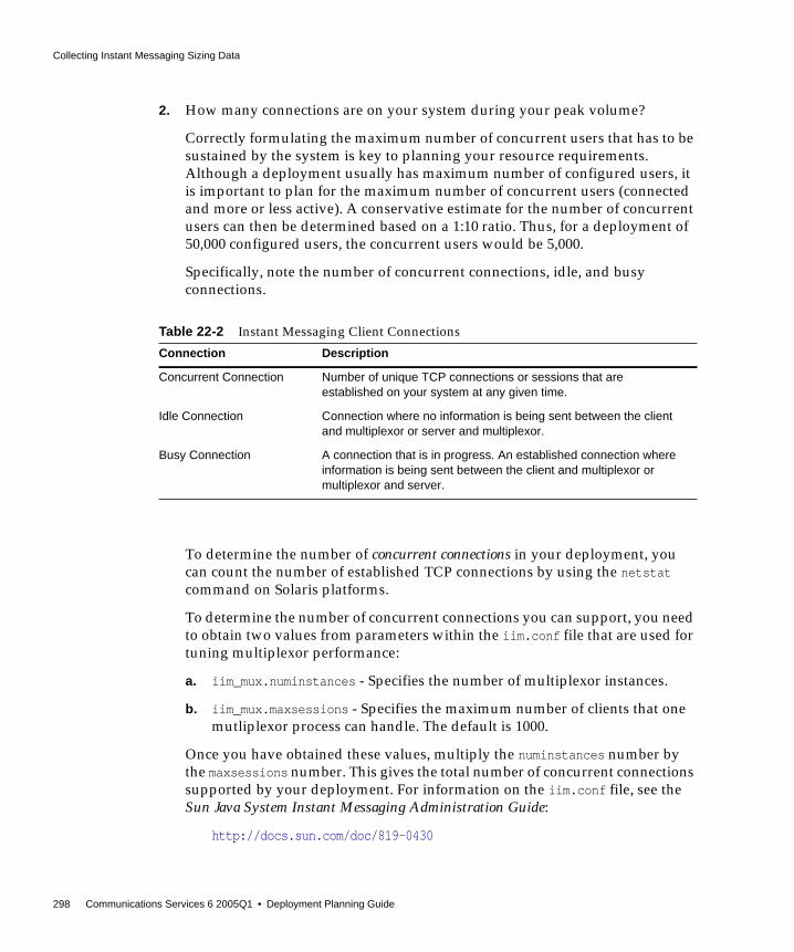
Collecting Instant Messaging Sizing Data
298 Communications Services 6 2005Q1 • Deployment Planning Guide
2. How many connections are on your system during your peak volume?
Correctly formulating the maximum number of concurrent users that has to besustained by the system is key to planning your resource requirements.Although a deployment usually has maximum number of configured users, itis important to plan for the maximum number of concurrent users (connectedand more or less active). A conservative estimate for the number of concurrentusers can then be determined based on a 1:10 ratio. Thus, for a deployment of50,000 configured users, the concurrent users would be 5,000.
Specifically, note the number of concurrent connections, idle, and busyconnections.
To determine the number of concurrent connections in your deployment, youcan count the number of established TCP connections by using the netstatcommand on Solaris platforms.
To determine the number of concurrent connections you can support, you needto obtain two values from parameters within the iim.conf file that are used fortuning multiplexor performance:
a. iim_mux.numinstances - Specifies the number of multiplexor instances.
b. iim_mux.maxsessions - Specifies the maximum number of clients that onemutliplexor process can handle. The default is 1000.
Once you have obtained these values, multiply the numinstances number bythe maxsessions number. This gives the total number of concurrent connectionssupported by your deployment. For information on the iim.conf file, see theSun Java System Instant Messaging Administration Guide:
http://docs.sun.com/doc/819-0430
Table 22-2 Instant Messaging Client Connections
Connection Description
Concurrent Connection Number of unique TCP connections or sessions that areestablished on your system at any given time.
Idle Connection Connection where no information is being sent between the clientand multiplexor or server and multiplexor.
Busy Connection A connection that is in progress. An established connection whereinformation is being sent between the client and multiplexor ormultiplexor and server.

Collecting Instant Messaging Sizing Data
Chapter 22 Planning an Instant Messaging Sizing Strategy 299
3. If you have a large deployment, how will you organize your users?
For example, consider placing active users on one server and inactive users onanother.
4. What is the amount of storage used for each user?
If you are not storing your end user data, such as contact lists, in LDAP, youneed to plan for the space required to store this data. If you configure theserver to store this data outside LDAP, the server stores it in a flat file. See theSun Java System Instant Messaging Administration Guide for more information:
http://docs.sun.com/doc/819-0430
5. How many messages enter your Instant Messaging system from the Internet?
The number of messages should be measured in messages per second duringyour peak volume.
6. How many messages are sent by your users to:
❍ End users on your system?
❍ The Internet?
This number of messages is also measured in messages per second during thepeak volume.
7. Will you be using SSL? If yes, what percentage of users and what type of users?
For example, in a particular organization, 20% of connections during peakhours will enable SSL.
Answering these questions provides a preliminary usage profile for yourdeployment. You can refine your usage profile as your Instant Messaging needschange.
Additional QuestionsWhile the following questions are not applicable to creating your usage profile,they are important to developing your sizing strategy. How you answer thesequestions might require you to consider additional hardware.
1. How much redundancy do you want in your deployment?
For example, do you need to consider high availability.

Collecting Instant Messaging Sizing Data
300 Communications Services 6 2005Q1 • Deployment Planning Guide
2. What backup and restore strategy do you have in place (such as disasterrecovery and site failover)? What are the expected times to accomplishrecovery tasks?
Typically you need to back up the server configuration files, database, and anyresource files you have customized.
Defining Your Instant Messaging User Base orSite ProfileOnce you establish a usage profile, compare it to sample pre-defined user basesthat are described in this section. A user base is made up of the types of InstantMessaging operations that your users will perform. Instant Messaging users fallinto one of these user bases:
• Casual Users
• Heavy Users
The sample user bases described in this section broadly generalize user behavior.Your particular usage profile might not exactly match the user bases; you will beable to adjust these differences when you run your load simulator (as described in“Using an Instant Messaging Load Simulator” on page 301).
Casual UsersA lightweight user base typically consists of users with simple Instant Messagingrequirements. These users rarely initiate chat sessions and rarely receiveinvitations. They might only use Instant Messaging as a presence tool.
Heavy UsersA heavy user uses significantly more system resources than a casual user. Typicalusage for a this type of user may be something like the following:
• Presence updates equal to or greater than 20 times a day.
• Contact list contains about 30 contacts.
• Subscribes to the presence updates of all the contacts in the contact list.
• Sets up around four conferences or chats per day where each conference hasthree people in the conference room and lasts an average of 10 minutes, and amessage is added to the conference every 1-15 seconds.

Using an Instant Messaging Load Simulator
Chapter 22 Planning an Instant Messaging Sizing Strategy 301
Using an Instant Messaging Load SimulatorTo measure the performance of your Instant Messaging architecture, use your userbases (described in “Defining Your Instant Messaging User Base or Site Profile” onpage 300) and your usage profile (described in “Creating Your Instant MessagingUsage Profile” on page 297) as inputs into a load simulator.
A load simulator creates a peak volume environment and calibrates the amount ofload placed on your servers. You can determine if you need to alter your hardware,throughput, or deployment architecture to meet your expected response time,without overloading your system. Using a load simulator involves five basic steps:
1. Defining the user base that you want to test (for example, casual users)
If necessary, adjust individual parameters to best match your usage profile.
2. Defining the hardware that will be tested
3. Running the load simulator and measuring the maximum number ofconcurrent connections on the tested hardware with the user base
4. Publishing your results and comparing those results with productiondeployments
5. Repeating this process using different user bases and hardware until you getthe response time that is within an acceptable range for your organizationunder peak load conditions
Understanding Instant Messaging SystemPerformance Guidelines
Once you evaluate your hardware and user base with a load simulator, you need toassess your system performance. The topics in this section address methods bywhich you can improve your overall system performance.
NOTE Contact Sun Client Services for recommended load simulators andsupport.

Understanding Instant Messaging System Performance Guidelines
302 Communications Services 6 2005Q1 • Deployment Planning Guide
Instant Messaging Memory UtilizationMake sure you have an adequate amount of physical memory on each machine inyour deployment. Additional physical memory improves performance and enablesthe Instant Messaging server to operate at peak volume. With sufficient memory,Instant Messaging can operate efficiently without excessive swapping.
For most deployments, you need at least 256 MB of RAM. The amount of RAMneeded depends on the number of concurrent client connections, and whether theserver and multiplexor are deployed on the same host. For information aboutconcurrent connections, see “Creating Your Instant Messaging Usage Profile” onpage 297. For information on hosting the server and multiplexor on the same host,see “Developing Instant Messaging Architectural Strategies” on page 305.
On Solaris systems, you can set the amount of memory allocated to the server bymodifying the iim.jvm.maxmemorysize parameter in the iim.conf file. Thisparameter specifies the maximum number of megabytes of memory that the JavaVirtual Machine (JVM) running the server is allowed to use. The default setting is256 MB, and the maximum setting is 500 MB. For instructions on modifying thisparameter, see the Sun Java System Instant Messaging Administration Guide:
http://docs.sun.com/doc/819-0430
You cannot currently change this value on Windows NT systems.
Instant Messaging Disk ThroughputDisk throughput is the amount of data that your system can transfer from memoryto disk and from disk to memory. The rate at which this data can be transferred iscritical to the performance of Instant Messaging. To improve efficiency in yoursystem’s disk throughput:
• Consider your maintenance operations, and ensure you have enoughbandwidth for backup. Backups can also affect network bandwidth,particularly remote backups. Private backup networks can be a more efficientalternative.
• Carefully partition the data stores to improve throughput efficiency.
• Ensure the user base is distributed across RAID (Redundant Array ofIndependent Disks) environments in large deployments. Typically, you makethis decision as part of the Directory Server deployment planning process.
• Stripe data across multiple disk spindles in order to speed up operations thatretrieve data from disk.

Understanding Instant Messaging System Performance Guidelines
Chapter 22 Planning an Instant Messaging Sizing Strategy 303
Instant Messaging Disk CapacityWhen planning Instant Messaging server system disk space, be sure to includespace for operating environment software, Instant Messaging software, and for anyservers not currently in your network that need to be installed to support InstantMessaging (such as LDAP). Be sure to use an external disk array. In addition, userdisk space needs to be allocated. Typically, this space is determined by your site’spolicy. Typical installations will require:
• Approximately 300 MB of free disk space for each server or multiplexor
• Approximately 5 K of disk space for each user
• Additional space for the Instant Messaging archive
The archive captures instant messages and archives them in a Portal ServerSearch database. End users can query and retrieve these archived messagesusing the Search page on the Portal Server desktop.
Use the following table to determine server and multiplexor disk space sizingnumbers whether archiving is enabled or disabled. The figures listed in the tablewere generated using a 400MHz Ultra SPARC II Processor.
Instant Messaging Network ThroughputNetwork throughput is the amount of data at a given time that can travel throughyour network between your client application and server. When a networkedserver is unable to respond to a client request, the client typically retransmits therequest a number of times. Each retransmission introduces additional systemoverhead and generates more network traffic.
Improving data integrity, system performance, and network congestion reducesthe number of retransmissions. Steps to do this involve:
Table 22-3 Instant Messaging Server and Multiplexor Memory Disk Space Sizing for Concurrent Users
Server MemoryConsumption forConnected/InactiveUsers
Server MemoryConsumption forConnected/Active Users
Multiplexor MemoryConsumption forConnected/InactiveUsers
Multiplexor MemoryConsumption forConnected/ActiveUsers
Archive Disabled 8 MB +20 K per User 120 MB + 20 K perUser
8 MB + 20 K per User 8MB + 28K per User
SSO/Portal/Archive enabled
100MB +25K perUser
120MB +30K perUser
8M+35K per user 8 MB +40K per user

Understanding Instant Messaging System Performance Guidelines
304 Communications Services 6 2005Q1 • Deployment Planning Guide
• Avoiding bottlenecks to ensure that the network infrastructure can handle theload
• Partitioning your network
• Not using theoretical maximum values when configuring your network toensure that sufficient capacity exists for future expansion
• Separating traffic flows on different network partitions to reduce collisions andto optimize bandwidth use.
Instant Messaging CPU ResourcesEnable enough CPU for your servers and multiplexing services. In addition, enableenough CPU for any RAID systems that you plan to use. If you intend to usearchiving in your deployment, you need to take those space requirements intoconsideration as well.
Use the following table to help determine the number of CPUs your installationrequires for optimum performance whether archive is enabled or disabled. Thefigures listed in the table were generated using a 400MHz Ultra SPARC IIProcessor.
Instant Messaging Multiplexor ConfigurationBest PracticesConsider the following suggestions and generalizations when planning yourmultiplexor deployment. The parameters discussed in this section are located inthe iim.conf file.
• The number of iim_mux.maxthreads should not exceed the number of CPUs onyour server.
Table 22-4 Instant Messaging CPU Utilization Numbers
Server CPUUtilization forConnected/InactiveUsers
Server CPUUtilization forConnected/Active Users
Multiplexor CPUUtilization forConnected/InactiveUsers
Multiplexor CPUUtilization forConnected/ActiveUsers
Archive Disabled Several hundredthousand users perCPU
30 K users perCPU
50 K users per CPU 5 K users per CPU

Developing Instant Messaging Architectural Strategies
Chapter 22 Planning an Instant Messaging Sizing Strategy 305
This helps maximize resource utilization and optimizes processing speed.
• The iim_mux.maxsessions value should be high enough to avoid rejectingconnections, but it should be reasonable enough so that the multiplexorprocesses to not get overloaded.
• Be sure that your expected number of concurrent client connections is less thanthe maximum possible by a safe margin.
• Do not configure threads or number of concurrent sessions to more than yourequire. Otherwise, you will unnecessarily consume system resources.
• A good starting point is to configure iim_mux.numinstances to the number ofCPUs on the system.
See the Sun Java System Instant Messaging Administration Guide for more detailedinformation about these parameters:
http://docs.sun.com/doc/819-0430
Developing Instant Messaging ArchitecturalStrategies
Once you have identified your system performance needs, the next step in sizingyour Instant Messaging deployment is to size specific components based on yourarchitectural decisions.
The topics in this section point out sizing considerations when you deploytwo-tiered and one-tiered architectures. Using load balancers with InstantMessaging is also discussed.
Two-tiered Instant Messaging ArchitectureA two-tiered architecture splits the Instant Messaging server deployment into twolayers: an access layer and a data layer. In a simplified two-tiered deployment, youmight add one or more multiplexors and servers to the access layer. Themultiplexor acts as a proxy for users, and the relays messages to the InstantMessaging server. The data layer holds the Instant Messaging server database andDirectory servers. Figure 22-1 on page 306 shows a simplified two-tiered InstantMessaging architecture.

Developing Instant Messaging Architectural Strategies
306 Communications Services 6 2005Q1 • Deployment Planning Guide
Figure 22-1 Simplified Two-tiered Instant Messaging Architecture
Two-tiered architectures have advantages over one-tiered architectures that canimpact your sizing decisions. Two-tiered architectures:
• Are easier to maintain than one-tiered architectures
• Enable the offloading of load-intensive processes like SSL, messagereprocessing
• Are easier for growth management and you can upgrade your system withlimited overall downtime
Sizing Your Multiplexing ServicesWhen you size your multiplexor, the calculation is based on your system load,particularly the number of concurrent connections the multiplexor needs to handle.
In addition, you must:
1. Add CPU or a hardware accelerator for SSL if appropriate.
2. Add memory to the machine if the multiplexor is being configured on it.
Data layer
Access layer
Instant Messaging Multiplexor
Instant Messaging Server
DirectoryServer(LDAP)
Internet
Clients

Developing Instant Messaging Architectural Strategies
Chapter 22 Planning an Instant Messaging Sizing Strategy 307
3. Account for denial of service.
4. Add capacity for load balancing and redundancy, if appropriate.
One or more of each type of machine should still handle peak load without asubstantial impact to throughput or response time when you plan forredundancy in your deployment.
One-tiered Instant Messaging ArchitectureIn a one-tiered architecture, there is no separation between access and data layers.The Instant Messaging server, multiplexor, and sometimes the Directory server areinstalled in one layer. The following figure illustrates the idea.
Figure 22-2 Simplified One-tiered Instant Messaging Architecture
One-tiered architectures have lower up-front hardware costs than two-tieredarchitectures. However, if you choose a one-tiered architecture, you need to allowfor significant maintenance windows.
To size a one-tiered architecture:
1. Add CPU for SSL, if necessary.
2. Account for denial of service attacks.
3. Add more disks for the increased number of client connections.
4. Add more disks for each multiplexor.
For specific instructions on sizing Instant Messaging components in one-tiered ortwo-tiered architectures, contact your Sun Client Services representative.
InstantMessagingMultiplexor
InstantMessaging
ServerDirectoryServer(LDAP)
Clients and internet

Example Instant Messaging Resource Requirements
308 Communications Services 6 2005Q1 • Deployment Planning Guide
Using Load Balancers With Instant MessagingInstant Messaging supports the use of load balancers located in front of the InstantMessaging multiplexors. However, you cannot currently use load balancersbetween the Instant Messaging multiplexors and the Instant Messaging server.
When deploying Instant Messaging as part of a Portal Server/Secure RemoteAccess deployment, you can locate load balancers between the Secure RemoteAccess gateway and the Instant Messaging multiplexors.
Example Instant Messaging ResourceRequirements
This section provides example resource distributions and recommended sizinginformation for the following two Instant Messaging deployment types:
• Small Deployment Sample Resource Requirements Numbers
• Large Deployment Sample Resource Requirements Numbers
Small Deployment Sample ResourceRequirements NumbersFor a small Instant Messaging deployment with the server and multiplexor on asingle server having 10,000 users with the following profile:
• 30 percent connected/active
• 20 percent connected/inactive
• 50 percent not connected
The memory requirements are: one or two CPUs with 300-500 MB RAM each.
NOTE If you just need security for the client connection, and not HTTPtunneling, consider using SSL instead of Secure Remote Access. Youcan configure a secure Instant Messaging client connection byenabling SSL on the multiplexors and locating them outside thefirewall.

Example Instant Messaging Resource Requirements
Chapter 22 Planning an Instant Messaging Sizing Strategy 309
Large Deployment Sample ResourceRequirements NumbersFor a large Instant Messaging deployment having 1,000,000 users with thefollowing profile:
• 5 percent connected/active
• 20 percent connected/inactive
• 75 percent not connected
The server memory requirements are 4 GB RAM on two CPUs. The multiplexorrequirement is 4 GB RAM on 16 CPUs.

Example Instant Messaging Resource Requirements
310 Communications Services 6 2005Q1 • Deployment Planning Guide

Chapter 23 Developing an Instant Messaging Architecture 311
Chapter 23
Developing an Instant MessagingArchitecture
This chapter describes a variety of Instant Messaging architectures. Depending onyour deployment, you will need to install different components. For example, tosupport email notification, you need to install an SMTP server. If you do not wantto support email notification, do not install an SMTP server.
For more detailed information about components that interoperate with InstantMessaging, see “Components Related to Instant Messaging” on page 283.
This chapter contains the following sections:
• Basic Instant Messaging Architecture
• Instant Messaging Email Notification (Calendar Alert) Architecture
• Instant Messaging Access Manager or SSO Architecture
• Instant Messaging Portal-based or Archiving Architecture
• Instant Messaging With All Features Enabled
• Instant Messaging Physical Deployment Examples
NOTE Currently, all deployment options are available on the Solarisplatform. A subset of the deployment options is available on Linuxand Windows operating systems.

Basic Instant Messaging Architecture
312 Communications Services 6 2005Q1 • Deployment Planning Guide
Basic Instant Messaging ArchitectureThe following figure shows the basic Instant Messaging architecture.
Figure 23-1 Basic Instant Messaging Architecture
Directory Server(LDAP)
Clients(browsers)
Clients(browsers)
InstantMessagingMultiplexor
InstantMessaging
Server
InstantMessagingResources
Web Server
InstantMessagingMultiplexor

Basic Instant Messaging Architecture
Chapter 23 Developing an Instant Messaging Architecture 313
The basic Instant Messaging architecture provides such functionality as chat, newsalerts, and conferences. To provide this basic functionality, you need to install thefollowing components:
• Instant Messaging server and one or more Instant Messaging multiplexors
• Instant Messaging resources
• Web server such as Sun Java System Web Server
• LDAP server such as Sun Java System Directory Server
In this example:
• The LDAP server provides user entries for authentication and lookup.
• The clients download the Instant Messaging resources from either a web serveror Sun Java System Application Server
• Clients always connect to the Instant Messaging server through an InstantMessaging multiplexor.
Authentication in a Basic ArchitectureFigure 23-2 on page 314 shows the interaction of the software components in theauthentication process of a basic architecture of Instant Messaging. The focus is onthe flow of authentication requests. An explanation of the steps in this processfollows the figure.

Basic Instant Messaging Architecture
314 Communications Services 6 2005Q1 • Deployment Planning Guide
Figure 23-2 Flow of Authentication Requests in a Basic Instant Messaging Architecture
The authentication process in a basic architecture works as follows:
1. End user accesses the Instant Messenger applet URL from a browser andchooses a method to invoke the client.
2. The browser invokes Java Web Start or the Java plugin.
3. Java Web Start or the Java plugin downloads the necessary Instant Messengerresource files and starts Instant Messenger.
Web Server
InstantMessagingApplet URL
InstantMessagingResources
Directory Server(LDAP)
Instant MessagingServer
Instant MessagingMultiplexor
Web Browser
2 1
3
4
5
Executes
Requests
InstantMessenger
Instant Messaging Email Notification (Calendar Alert) Architecture
Chapter 23 Developing an Instant Messaging Architecture 315
4. The login window appears and the end user enters the login name andpassword. The login data is sent to the Instant Messaging server through themultiplexor.
5. The Instant Messaging server communicates with the LDAP server toauthenticate the end user and to request end-user information, such as contactlists or subscriptions.
When the end-user authentication is complete, the Instant Messaging mainwindow appears, displaying the contact list for the end user. The end user can nowstart and participate in Instant Messaging sessions with the other end users.
Instant Messaging Email Notification (CalendarAlert) Architecture
You can deploy Instant Messaging to support email notification to offline users, aswell as Instant Messaging based notification of calendar events to users.
An Instant Messaging architecture that supports email notification and calendaralerts provides the same functionality as “Basic Instant Messaging Architecture”on page 312. To provide this functionality, you need to include the componentslisted in “Basic Instant Messaging Architecture” on page 312. To support emailalerts, you also install an SMTP server such as Sun Java System Messaging Server.To support calendar alerts, you also install Sun Java System Calendar Server.
To enable email notification, you are prompted to identify the SMTP server to usewith Instant Messaging during installation. If you do not have an SMTP serverinstalled, you must install one before installing the Instant Messaging software.Figure 23-3 on page 316 shows Instant Messaging with email notification enabledon the network.
If you do not have Calendar Server installed, you must install it before installingthe Instant Messaging software. Figure 23-4 on page 317 shows Instant Messagingwith calendar notification enabled on the network.
Authentication flow in this architecture is the same as in a basic deployment. See“Authentication in a Basic Architecture” on page 313 for more information.
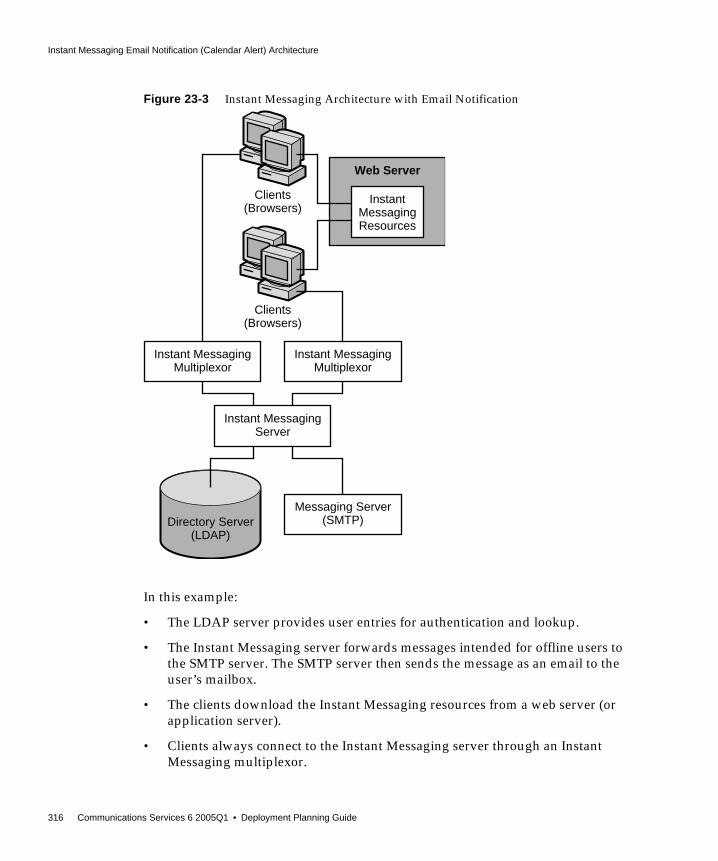
Instant Messaging Email Notification (Calendar Alert) Architecture
316 Communications Services 6 2005Q1 • Deployment Planning Guide
Figure 23-3 Instant Messaging Architecture with Email Notification
In this example:
• The LDAP server provides user entries for authentication and lookup.
• The Instant Messaging server forwards messages intended for offline users tothe SMTP server. The SMTP server then sends the message as an email to theuser’s mailbox.
• The clients download the Instant Messaging resources from a web server (orapplication server).
• Clients always connect to the Instant Messaging server through an InstantMessaging multiplexor.
Directory Server(LDAP)
Clients(Browsers)
Clients(Browsers)
InstantMessagingResources
Web Server
Instant MessagingMultiplexor
Messaging Server(SMTP)
Instant MessagingServer
Instant MessagingMultiplexor
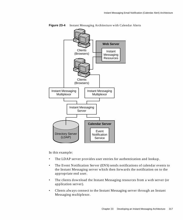
Instant Messaging Email Notification (Calendar Alert) Architecture
Chapter 23 Developing an Instant Messaging Architecture 317
Figure 23-4 Instant Messaging Architecture with Calendar Alerts
In this example:
• The LDAP server provides user entries for authentication and lookup.
• The Event Notification Server (ENS) sends notifications of calendar events tothe Instant Messaging server which then forwards the notification on to theappropriate end user.
• The clients download the Instant Messaging resources from a web server (orapplication server).
• Clients always connect to the Instant Messaging server through an InstantMessaging multiplexor.
Directory Server(LDAP)
Clients(Browsers)
Clients(Browsers)
InstantMessagingResources
Web Server
EventNotification
Service
Calendar Server
Instant MessagingMultiplexor
Instant MessagingServer
Instant MessagingMultiplexor
Instant Messaging Access Manager or SSO Architecture
318 Communications Services 6 2005Q1 • Deployment Planning Guide
Instant Messaging Access Manager or SSOArchitecture
You can deploy Instant Messaging to use Access Manager policy features andsingle sign-on (SSO). An Instant Messaging architecture that uses Access Managerprovides the same functionality as “Basic Instant Messaging Architecture” onpage 312. To provide this functionality, you need to install the components listed in“Basic Instant Messaging Architecture” on page 312 and also install AccessManager. In addition, you need to install the Access Manager SDK on the InstantMessaging server host.
In this architecture, Instant Messaging uses the directory to search for users but notto authenticate or authorize them. Instead, Access Manager is responsible forauthenticating and authorizing users.
If you are planning on using SSO with Access Manager, you must configure AccessManager and Instant Messaging to use the same web container.
Figure 23-5 on page 319 shows the Instant Messaging Access Manager architecture.

Instant Messaging Access Manager or SSO Architecture
Chapter 23 Developing an Instant Messaging Architecture 319
Figure 23-5 Instant Messaging Architecture With Access Manager-based Server Policy Management orSingle Sign On
In this example:
• The LDAP server provides user entries.
• The web server (can also be an application server, which includes a web server)downloads the Instant Messaging resources via a browser to the clients. Theresources are basically the client.
• Clients always connect through a multiplexor.
• Instant Messaging related services provided by the Access Manager includethe presence service and the Instant Messaging service.
Clients(Browsers)
Clients(Browsers)
AccessManager
IMService
Web Server
Directory Server(LDAP)
Instant MessagingMultiplexor
Instant MessagingServer
AccessManager SDK
Instant MessagingMultiplexor

Instant Messaging Access Manager or SSO Architecture
320 Communications Services 6 2005Q1 • Deployment Planning Guide
• The web server can be used to access the Access Manager administrationinterface, which manages the identity-based services for the Instant Messagingdeployment. The Web server for Access Manager can be the same as the onethat serves the Instant Messaging resources. See the Access Managerdocumentation for more details.
• The Access Manager SDK provides the API used by the Instant Messagingserver to interact with the Access Manager.
Authentication in an Access Manager OnlyArchitectureFigure 23-6 on page 321 illustrates the authentication process used by the InstantMessaging software in collaboration with Portal Server and Access Managercomponents in a single sign-on environment. As with Figure 23-2 on page 314, thisfigure focuses on the flow of authentication requests. An explanation of the steps inthis process follows the figure.

Instant Messaging Access Manager or SSO Architecture
Chapter 23 Developing an Instant Messaging Architecture 321
Figure 23-6 Flow of Authentication Requests in an Access Manager Configuration
The authentication process of the Instant Messaging server in this deploymentwithin a single sign-on environment works as follows:
1. The end user logs in to the Access Manager server by entering the URL in aweb browser.
Web or Application Server
InstantMessagingResources
AppletURL
Directory Server(LDAP)
Instant MessagingMultiplexor
1
3
2
6
8
7
Executes
Requests
Web Browser
4
5InstantMessenger
Instant MessagingServer
IdentityServer
IMService

Instant Messaging Portal-based or Archiving Architecture
322 Communications Services 6 2005Q1 • Deployment Planning Guide
2. The Access Manager software authenticates the end user and returns a sessiontoken.
The session token is what enables single sign-on to work. This token isprovided as an applet parameter and is used throughout the authenticationprocess. End users are not asked for their credentials again as long as thesession token is present.
3. End user accesses the Instant Messenger applet URL from a browser andchooses a method to invoke the client.
4. The browser invokes Java Web Start or the Java plugin as appropriate.
5. Java Web Start or the Java plugin downloads the necessary Instant Messengerresource files and starts Instant Messenger.
6. Instant Messenger requests authentication to the Instant Messaging serverusing the session token.
7. The Instant Messaging server asks Access Manager to validate the sessiontoken. If the session is valid, Instant Messenger displays the end user’s contactlist and the end user can then use Instant Messenger services: chat, alerts, polls,etc.
8. The Instant Messaging server must query LDAP directly to get or set end-userinformation, such as contact lists or subscriptions.
Instant Messaging Portal-based or ArchivingArchitecture
You can deploy Instant Messaging to support message archiving, and to runInstant Messaging in secure mode. An Instant Messaging architecture thatprovides for this functionality also provides the same functionality as “BasicInstant Messaging Architecture” on page 312. In addition, the Instant Messengerclient is made available to end users through the Portal Server desktop. To providethis functionality, you need to install the components listed in “Basic InstantMessaging Architecture” on page 312 and also install Portal Server and AccessManager.
This architecture uses the directory and Web servers accessed by the AccessManager. You do not need to install additional instances of those servers. Inaddition, because this architecture requires Access Manager, all the featuresdescribed in “Instant Messaging Access Manager or SSO Architecture” on page 318are also available.

Instant Messaging Portal-based or Archiving Architecture
Chapter 23 Developing an Instant Messaging Architecture 323
The following figure shows the Instant Messaging Portal-based architecture.
Figure 23-7 Instant Messaging Architecture With Portal-based Secure Mode or Archiving
In this example:
• The LDAP server provides user entries.
• The web server (can also be an application server, which includes a web server)downloads the Instant Messaging resources via a browser to the clients. Theresources are basically the client.
• Clients are always connect through an Instant Messaging multiplexor.
AccessManager
Web or Application Server
PortalServer
IMChannel
ArchiveSearch
Clients(Browsers)
Clients(Browsers)
IMService
Directory Server(LDAP)
Instant MessagingMultiplexor
Instant MessagingServer
Instant MessagingMultiplexor
AccessManager SDK
Instant Messaging Portal-based or Archiving Architecture
324 Communications Services 6 2005Q1 • Deployment Planning Guide
• Instant Messaging related services provided by Access Manager include thepresence service and the Instant Messaging service.
• The web server can be used to access the Access Manager administrationinterface, which manages the identity-based services for the Instant Messagingdeployment. The web server for both Access Manager and Portal Server can bethe same as the one that serves the Instant Messaging resources. See the SunJava System Access Manager and Sun Java System Portal Serverdocumentation for more details.
• The Access Manager SDK provides the API used by the Instant Messagingserver to interact with the Access Manager.
• The Instant Messaging channel is supported by Portal Server and enables usersto access Instant Messenger from the Portal Desktop.
• Portal Server provides archive functionality that allows you to save instantmessages sent through the deployment.
Authentication in a Portal Server ArchitectureFigure 23-8 on page 325 illustrates authentication process used by the InstantMessaging software in collaboration with Portal Server and Access Managercomponents in a single sign-on environment. As with Figure 23-2 on page 314, thisfigure focuses on the flow of authentication requests. An explanation of the steps inthis process follows the figure.

Instant Messaging Portal-based or Archiving Architecture
Chapter 23 Developing an Instant Messaging Architecture 325
Figure 23-8 Flow of Authentication Requests in a Portal Server and Access Manager Configuration
The authentication process of the Instant Messaging server in this deploymentwithin a single sign-on environment works as follows:
1. The end user logs in to the Portal Server by entering the URL in a web browser.
2. The Access Manager software authenticates the end user and returns a sessiontoken and the Portal Server downloads the Desktop for the end user. ThePortal Server Desktop is displayed in the end user’s browser. See Step 6 for anexplanation of the session token.
3. The end user clicks the Instant Messenger URL link from the Instant Messagingchannel on the Desktop.
Web or Application Server
InstantMessagingResources
AppletURL
Directory Server(LDAP)
Instant MessagingMultiplexor
1
3
5
2
6
8
7
Executes
Requests
AccessManager
InstantMessenger
Web Browser
4
Portal Server
PortalDesktop
IMChannel
Instant MessagingServer

Instant Messaging With All Features Enabled
326 Communications Services 6 2005Q1 • Deployment Planning Guide
4. The browser invokes Java Web Start or the Java plugin.
5. Java Web Start or the Java plugin downloads the necessary Instant Messengerresource files and starts the Instant Messenger.
6. Instant Messenger requests authentication to the Instant Messaging serverusing the session token.
The session token is what enables single sign-on to work. This token isprovided as an applet parameter and is used throughout the authenticationprocess. End users are not asked for their credentials again as long as thesession token is present.
7. The Instant Messaging server asks Access Manager to validate the sessiontoken. If the session is valid, Instant Messenger displays the end user’s contactlist and the end user can then use Instant Messenger services: chat, alerts, polls,and so forth.
8. The Instant Messaging server must query LDAP directly to get or set end-userinformation, such as contact lists or subscriptions.
Instant Messaging With All Features EnabledYou can deploy Instant Messaging and enable all the features listed in this sectionby installing:
• The following components before you install Instant Messaging:
❍ Directory Server (during Access Manager installation)
❍ Web Server (during Access Manager installation)
❍ Access Manager
❍ Portal Server
❍ Calendar Server
❍ Messaging Server
• Instant Messaging resources on the Web Server host
• Access Manager SDK on the Instant Messaging server host
You also need to configure the Access Manager Instant Messaging Service on theAccess Manager host.

Instant Messaging Physical Deployment Examples
Chapter 23 Developing an Instant Messaging Architecture 327
Instant Messaging Physical DeploymentExamples
This section explains variations to the deployment scenario described in “BasicInstant Messaging Architecture” on page 312. For example, you can install thevarious required servers and components in the following physical configurations:
• Instant Messaging Physical Deployment Example: Web Server on SeparateHost
• Instant Messaging Physical Deployment Example: Multiplexors on SeparateHosts
• Instant Messaging Physical Deployment Example: Multiple Instant MessagingHosts
• Any combination or all of the above
These variations can be applied in any of the architectures described in thischapter. You might choose to include them based on your deploymentrequirements.
Instant Messaging Physical DeploymentExample: Web Server on Separate HostFigure 23-9 on page 328 shows a configuration consisting of the Instant Messagingserver and multiplexor installed on the same host. The web server is installed on aseparate host. The Instant Messaging resources are also present on the web serverhost. Use this configuration when there is an existing instance of a web server andan LDAP server, and you do not want to install other applications on these hosts.

Instant Messaging Physical Deployment Examples
328 Communications Services 6 2005Q1 • Deployment Planning Guide
Figure 23-9 Separate Web Server and Instant Messaging Hosts
Instant Messaging Physical DeploymentExample: Multiplexors on Separate HostsFigure 23-10 on page 329 shows a configuration consisting of two multiplexorsinstalled on two separate hosts.The Instant Messaging server is installed on adifferent host. This configuration enables you to place a multiplexor outside yourcompany’s firewall. Installing multiplexors on multiple hosts distributes the loadof the Instant Messaging server across multiple systems.
NOTE The multiplexor can be resource-intensive, so putting it on aseparate host can improve the overall performance of the system.
Windows supports only one multiplexor instance per host.
Directory Server(LDAP) Host
Instant MessagingServer and
Instant MessagingMultiplexor Host
Client Hosts
InstantMessagingResources
Web Server Host

Instant Messaging Physical Deployment Examples
Chapter 23 Developing an Instant Messaging Architecture 329
Figure 23-10 Instant Messaging Multiplexors Installed on Separate Hosts
Instant Messaging Physical DeploymentExample: Multiple Instant Messaging HostsFigure 23-11 on page 330 shows a configuration consisting of two InstantMessaging servers. This configuration is used when the site contains multipleadministrative domains. The server configuration on each Instant Messagingserver host has to be set up so that end users on one Instant Messaging server cancommunicate with end users on other Instant Messaging servers.
Directory Server(LDAP) Host
Client Hosts
Client Hosts
InstantMessagingResources
Web Server Host
Instant MessagingMultiplexor Host 2
Instant MessagingServer Host
Instant MessagingMultiplexor Host 1

Instant Messaging Physical Deployment Examples
330 Communications Services 6 2005Q1 • Deployment Planning Guide
Figure 23-11 Multiple Instant Messaging Server Hosts
Directory Server(LDAP) Host 1
Instant MessagingServer and
Instant MessagingMultiplexor Host 1
Client Hosts
InstantMessagingResources
Web Server Host
Directory Server(LDAP) Host 2
Instant MessagingServer and
Instant MessagingMultiplexor Host 2
Client Hosts
InstantMessagingResources
Web Server Host

331
Chapter 24
Understanding Instant MessagingPre-Installation Considerations
This chapter describes considerations you need to think about before installingInstant Messaging. See the Sun Java Enterprise System 2005Q1 Installation Guide forinstructions on running the Java Enterprise System installer.
This chapter contains the following sections:
• Installing Instant Messaging Overview
• Instant Messaging Worksheets
Installing Instant Messaging OverviewTo install Instant Messaging on a Solaris system, you use the Java EnterpriseSystem installer. On Linux and Windows systems, you use the setup programincluded in the Linux and Windows Media Kit CD. Optionally, you can downloadthe software from the following site:
http://www.sun.com/software/download/
The Java Enterprise System and Instant Messaging documentation provideprocedures and tools for completing and upgrading your installation, forconfiguring your servers, setting up clients, and so on. For more information onthese additional installation and configuration steps, see the following:
Sun Java Enterprise System 2005Q1 Installation Guidehttp://docs.sun.com/doc/819-0056
Sun Java Enterprise System 2005Q1 Upgrade and Migration Guidehttp://docs.sun.com/doc/819-0062

Instant Messaging Worksheets
332 Communications Services 6 2005Q1 • Deployment Planning Guide
Sun Java System Instant Messaging Administration Guidehttp://docs.sun.com/doc/819-0430
Before you begin an installation, see the Instant Messaging Release Notes forhardware and software requirements and supported versions:
http://docs.sun.com/doc/819-0428
Prior to installing Instant Messaging, you need to install a directory server, webserver, and optionally a messaging server. On Solaris systems, you might also needto install Access Manager and Portal Server if you intend to use functionalityprovided by those servers with Instant Messaging. Interoperating with otherservers is described in “Components Related to Instant Messaging” on page 283. Inaddition, Chapter 23, “Developing an Instant Messaging Architecture” providessome architectures that you can follow to enable various Instant Messagingfeatures.
Instant Messaging WorksheetsDuring installation and upgrade, you will be prompted for basic configurationinformation. You should gather this information before you begin. You will beprompted for some or all of the information depending on the components youdecide to install.
Print out Table 24-1 and write the values for your deployment in the spaceprovided. You can reuse this installation worksheet for multiple installations,uninstallation, or for upgrades. This table contains passwords and other sensitiveinformation, so you should store this information in a safe place.
Table 24-1 Communications Services Installation Parameters
Parameter Description Your Answers
InstallationDirectory
instant-messaging-install-dir or installation directory.
Directory in which Instant Messaging is installed.
Defaults:
Solaris system: /opt/SUNWiim
Linux system: /opt/sun/im
Windows system: C:\ProgramFiles\Sun\Instant Messaging

Instant Messaging Worksheets
Chapter 24 Understanding Instant Messaging Pre-Installation Considerations 333
InstantMessagingServer Host andDomain Name
Host name on which Instant Messaging is installedand the domain name associated with the host. Forexample:
Host Name: instantmessaging.siroe.com
Domain Name: siroe.com
InstantMessagingServer PortNumber
The port number on which the Instant Messagingserver listens for incoming requests other than thosesent by Instant Messenger clients.
Default: 49999
Multiplexor PortNumber(MultiplexorConfigurationOnly)
The port number on which the Instant Messagingserver listens for incoming requests from InstantMessenger clients.
Default: 49909
Disable Server Select this option if the instance you installed will actas a multiplexor and not a server. If you select thisoption, you must provide a value for Remote InstantMessaging Server Host Name (MultiplexorConfiguration Only).
Remote InstantMessagingServer HostName(MultiplexorConfigurationOnly)
The host name of the Instant Messaging server forwhich this multiplexor routes messages. Do notenter a value for this parameter if the installedinstance you are configuring is an InstantMessaging server and not a multiplexor.
Dependencies: The Disable Server parameter mustbe selected, that is, server functionality is disabled.
Assign InstantMessagingServices toexisting users(Optional)
If selected, this option enables Instant Messagingfor existing Access Manager users.
Dependencies: Portal Server and Access Manager.
Table 24-1 Communications Services Installation Parameters (Continued)
Parameter Description Your Answers
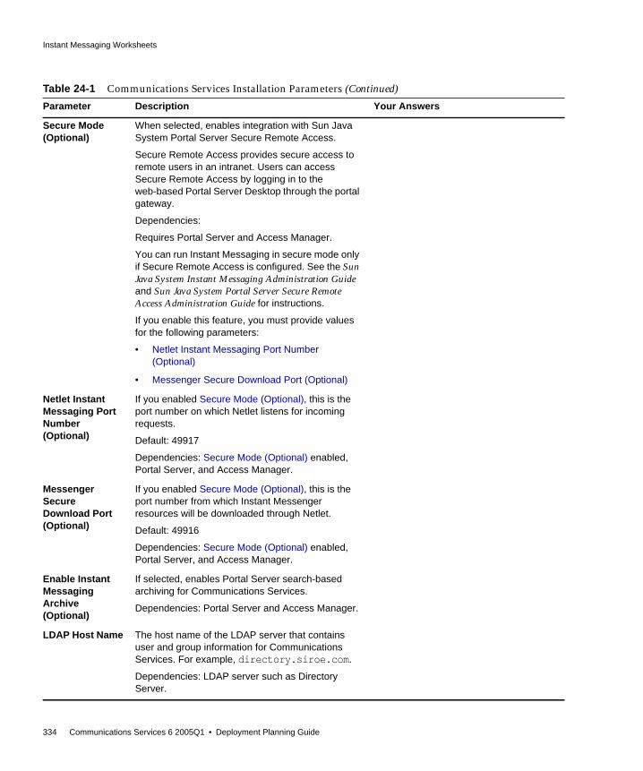
Instant Messaging Worksheets
334 Communications Services 6 2005Q1 • Deployment Planning Guide
Secure Mode(Optional)
When selected, enables integration with Sun JavaSystem Portal Server Secure Remote Access.
Secure Remote Access provides secure access toremote users in an intranet. Users can accessSecure Remote Access by logging in to theweb-based Portal Server Desktop through the portalgateway.
Dependencies:
Requires Portal Server and Access Manager.
You can run Instant Messaging in secure mode onlyif Secure Remote Access is configured. See the SunJava System Instant Messaging Administration Guideand Sun Java System Portal Server Secure RemoteAccess Administration Guide for instructions.
If you enable this feature, you must provide valuesfor the following parameters:
• Netlet Instant Messaging Port Number(Optional)
• Messenger Secure Download Port (Optional)
Netlet InstantMessaging PortNumber(Optional)
If you enabled Secure Mode (Optional), this is theport number on which Netlet listens for incomingrequests.
Default: 49917
Dependencies: Secure Mode (Optional) enabled,Portal Server, and Access Manager.
MessengerSecureDownload Port(Optional)
If you enabled Secure Mode (Optional), this is theport number from which Instant Messengerresources will be downloaded through Netlet.
Default: 49916
Dependencies: Secure Mode (Optional) enabled,Portal Server, and Access Manager.
Enable InstantMessagingArchive(Optional)
If selected, enables Portal Server search-basedarchiving for Communications Services.
Dependencies: Portal Server and Access Manager.
LDAP Host Name The host name of the LDAP server that containsuser and group information for CommunicationsServices. For example, directory.siroe.com.
Dependencies: LDAP server such as DirectoryServer.
Table 24-1 Communications Services Installation Parameters (Continued)
Parameter Description Your Answers
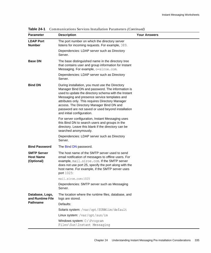
Instant Messaging Worksheets
Chapter 24 Understanding Instant Messaging Pre-Installation Considerations 335
LDAP PortNumber
The port number on which the directory serverlistens for incoming requests. For example, 389.
Dependencies: LDAP server such as DirectoryServer.
Base DN The base distinguished name in the directory treethat contains user and group information for InstantMessaging. For example, o=siroe.com.
Dependencies: LDAP server such as DirectoryServer.
Bind DN During installation, you must use the DirectoryManager Bind DN and password. The information isused to update the directory schema with the InstantMessaging and presence service templates andattributes only. This requires Directory Manageraccess. The Directory Manager Bind DN andpassword are not saved or used beyond installationand initial configuration.
For server configuration, Instant Messaging usesthis Bind DN to search users and groups in thedirectory. Leave this blank if the directory can besearched anonymously.
Dependencies: LDAP server such as DirectoryServer.
Bind Password The Bind DN password.
SMTP ServerHost Name(Optional)
The host name of the SMTP server used to sendemail notification of messages to offline users. Forexample, mail.siroe.com. If the SMTP serverdoes not use port 25, specify the port along with thehost name. For example, if the SMTP server usesport 1025:
mail.siroe.com:1025
Dependencies: SMTP server such as MessagingServer.
Database, Logs,and Runtime FilePathname
The location where the runtime files, database, andlogs are stored.
Defaults:
Solaris system: /var/opt/SUNWiim/default
Linux system: /var/opt/sun/im
Windows system: C:\ProgramFiles\Sun\Instant Messaging
Table 24-1 Communications Services Installation Parameters (Continued)
Parameter Description Your Answers

Instant Messaging Worksheets
336 Communications Services 6 2005Q1 • Deployment Planning Guide
Resources andHelp FilesPathname
instant-messaging-resource-directory or resourcedirectory
The directory in which the resource and online helpfiles are installed.
Defaults:
Solaris system: /opt/SUNWiim/html
Linux system: /opt/sun/im/html
Windows system: C:\ProgramFiles\Sun\Instant Messaging\html
Code Base The URL from which Instant Messenger downloadsresources.
You install the resources into the web server’s docroot. For example, assume that the web serverwww.example.com listens on port 89, the doc rootfor this web server is /opt/web/, and you chooseto install the messenger resources in/opt/web/im, then the messenger resourcescodebase is as follows:
http://www.example.com:89/im/
If you do not provide the correct codebase duringinstallation, you need to update the messengerlaunch pages codebase/lang/im[ssl].html andcodebase/lang/im[ssl].jnlp with the correct URL.
On UNIX, it is possible to install the resources in adirectory and use a symbolic link to make theresources visible to the web server.
For instance, if in the above example you installedthe resources in /opt/SUNWiim/html, themessenger resources can be made visible to theweb server by creating the following symbolic link.
ln -s /opt/SUNWiim/html /opt/web/im
See the Sun Java System Instant MessagingAdministration Guide, and your web serverdocumentation for more information.
Table 24-1 Communications Services Installation Parameters (Continued)
Parameter Description Your Answers

Part V
Deploying Communications Express
Chapter 25, “Introduction to Communications Express Software”
Chapter 26, “Developing a Communications ExpressArchitecture”
Chapter 27, “Understanding Communications ExpressPre-Installation Considerations”

339
Chapter 25
Introduction to CommunicationsExpress Software
Communications Express provides an integrated web-based communications andcollaboration client. Communications Express is a common part of MessagingServer and Calendar Server, providing end users with a web interface to theircalendar information and mail, as well as an address book.
Communications Express consists of three client modules: Calendar, AddressBook, and Mail.
This chapter contains the following sections:
• Communications Express Overview
• Communications Express Features
• Communications Express High-Level Architecture
Communications Express OverviewCommunications Express depends upon the following Sun Java Systemcomponent products:
• Directory Server
• Access Manager (if you are using Sun Java System LDAP Schema Version 2)
• Calendar Server
• Messaging Server
• Web Server or Application Server (for the web container)

Communications Express Features
340 Communications Services 6 2005Q1 • Deployment Planning Guide
You install Communications Express as a front-end server (in a multi-tierenvironment). You must install the complete set of Messaging Server packages onthe same host that Communications Express is running on. Also, bothCommunications Express and Messenger Express must run on the same IPaddress. The Messaging Server packages can then be configured to run asMessenger Express or as MEM, which connects to a back-end store runningMessenger Express.
In addition, you can configure Communications Express to have the Address Bookon the front-end machine store its data either in the LDAP directory infrastructureor on an LDAP server other than the Communications Express machine. See theSun Java Communications Express Administration Guide for more information:
http://docs.sun.com/doc/819-0115
Communications Express communicates with Calendar Server through theCalendar Server HTTP service, the mshttpddaemons for Messaging Server, and theLDAP service for address book. The cshttpd daemon can be local or remote, themshttpd daemon can be either the local Webmail server or MEM, and the LDAPservice can be either local or remote.
When using a load balancer or port director type device, make sure to utilize“sticky” (persistent) connections such that users are continually routed to the samefront-end server for the duration of their session.
Communications Express Features• Communications Express has an integrated user interface for calendar, mail,
and address book and enables the access of one client module from anotherwithout re-authenticating user credentials.
• Communication between mail and calendar is established using AccessManager or Messaging Server single sign-on mechanism.
• Both calendar and mail applications share the same address book.
• All modules share the common user preferences specified in the Options tab ofCommunications Express.
• The Address Book Store provides horizontal scalability. See the Sun JavaCommunications Express Administration Guide for more information:
http://docs.sun.com/doc/819-0115
• Communications Express supports virtual domains.
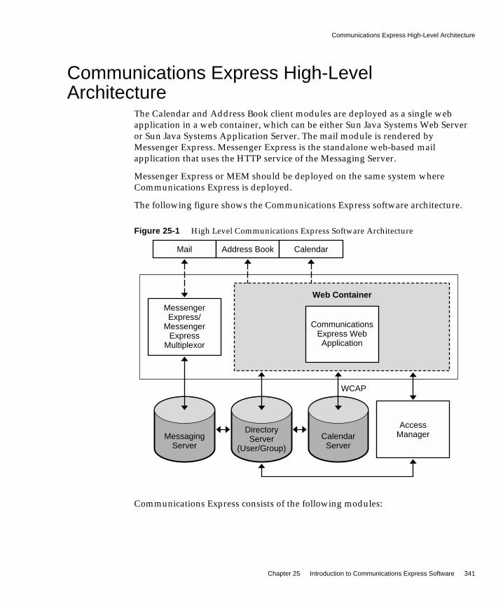
Communications Express High-Level Architecture
Chapter 25 Introduction to Communications Express Software 341
Communications Express High-LevelArchitecture
The Calendar and Address Book client modules are deployed as a single webapplication in a web container, which can be either Sun Java Systems Web Serveror Sun Java Systems Application Server. The mail module is rendered byMessenger Express. Messenger Express is the standalone web-based mailapplication that uses the HTTP service of the Messaging Server.
Messenger Express or MEM should be deployed on the same system whereCommunications Express is deployed.
The following figure shows the Communications Express software architecture.
Figure 25-1 High Level Communications Express Software Architecture
Communications Express consists of the following modules:
MessagingServer
Mail Address Book Calendar
CommunicationsExpress WebApplication
MessengerExpress/
MessengerExpress
Multiplexor
AccessManager
Web Container
DirectoryServer
(User/Group)CalendarServer
WCAP

Communications Express High-Level Architecture
342 Communications Services 6 2005Q1 • Deployment Planning Guide
• Mail. The Mail component uses the JavaScript language that is read andinterpreted by the client. The JavaScript files are located on the server anddownloaded to the client. The client extracts data from the JavaScript code tocustomize Communications Express functions. All modifications andcustomizations are done on the server.
• Calendar. The presentation layer of the Calendar module is based onJavaServer Pages™. These JavaServer Pages pages can be customized to suitthe requirements of the client. The data layer accesses a Java API for Calendar(JCAPI) to enable exchange of data with Calendar Server over HTTP-basedprotocol.
• Address Book. The Address Book component uses XML/XSL files that containXSL tags, static HTML and .js scripts. The XSL and JavaScript code are usedto display dynamic data. These XSL files can be edited for customizing theAddress Book component.

343
Chapter 26
Developing a CommunicationsExpress Architecture
This chapter contains Communications Express basic deployment architectures.Depending on the features you want to implement in your deployment, you willneed to install different sets of hosts and other networking infrastructure.
This chapter contains the following sections:
• Basic Communications Express Architecture
• Communications Express on Remote Host Architecture
Basic Communications Express ArchitectureThis basic Communications Express architecture provides Calendar, AddressBook, and Mail modules in a web container on a single host. Messenger Express isthe standalone web interface mail application that uses the HTTP service of theMessaging Server. Messenger Express is deployed on the same system as theCalendar and Address Book modules.
To provide this basic functionality, you need to install the following components:
• Directory Server
• Access Manager (If you are using Sun Java System LDAP Schema Version 2)
• Calendar Server
• Messaging Server
• Web Server or Application Server (for the web container)

Basic Communications Express Architecture
344 Communications Services 6 2005Q1 • Deployment Planning Guide
In this example:
• You install the complete set of Messaging Server packages on the host thatCommunications Express is running on.
• The AddressBook server of Communications Express is configured to store itsdata in the LDAP directory infrastructure.
• SSL has not been configured.
The following figure shows the basic Communications Express architecture.
Figure 26-1 Basic Communications Express Architecture
Tier 1
User Tier
MessagingServer
Other systems
Users
CalendarServer
80
81
82389
25
Storage
Host
CommunicationsExpress
Web Container
Directory/Access
Manager
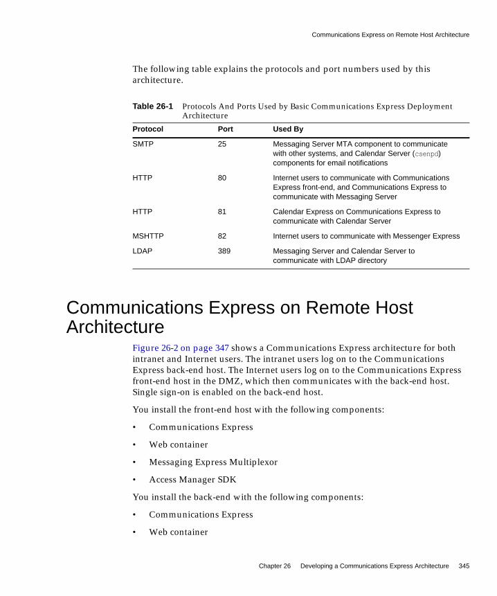
Communications Express on Remote Host Architecture
Chapter 26 Developing a Communications Express Architecture 345
The following table explains the protocols and port numbers used by thisarchitecture.
Communications Express on Remote HostArchitecture
Figure 26-2 on page 347 shows a Communications Express architecture for bothintranet and Internet users. The intranet users log on to the CommunicationsExpress back-end host. The Internet users log on to the Communications Expressfront-end host in the DMZ, which then communicates with the back-end host.Single sign-on is enabled on the back-end host.
You install the front-end host with the following components:
• Communications Express
• Web container
• Messaging Express Multiplexor
• Access Manager SDK
You install the back-end with the following components:
• Communications Express
• Web container
Table 26-1 Protocols And Ports Used by Basic Communications Express DeploymentArchitecture
Protocol Port Used By
SMTP 25 Messaging Server MTA component to communicatewith other systems, and Calendar Server (csenpd)components for email notifications
HTTP 80 Internet users to communicate with CommunicationsExpress front-end, and Communications Express tocommunicate with Messaging Server
HTTP 81 Calendar Express on Communications Express tocommunicate with Calendar Server
MSHTTP 82 Internet users to communicate with Messenger Express
LDAP 389 Messaging Server and Calendar Server tocommunicate with LDAP directory
Communications Express on Remote Host Architecture
346 Communications Services 6 2005Q1 • Deployment Planning Guide
• Messaging Server (Messenger Express)
• Calendar Server
• Directory Server
• Access Manager
Figure 26-2 on page 347 shows the Communications Express on remote hostarchitecture.

Communications Express on Remote Host Architecture
Chapter 26 Developing a Communications Express Architecture 347
Figure 26-2 Communications Express on Remote Host Architecture
AccessManager SDK
MEM
DirectoryServer
AccessManager
Internet Users
Intranet Users
DMZ
80
81
82 801
389
Firewall
Firewall
Host
Host
CommunicationsExpress
Web Container
CommunicationsExpress
Web Container
CalendarServer
MessengerExpress

Communications Express on Remote Host Architecture
348 Communications Services 6 2005Q1 • Deployment Planning Guide
The following table explains the protocols and port numbers used by thisarchitecture.
Table 26-2 Protocols And Ports Used by Communications Express Remote HostDeployment Example
Protocol Port Used By
HTTP 80 Internet users to communicate with theCommunications Express front-end host in the DMZ
HTTP 81 Messaging Express Multiplexor (MEM) on theCommunications Express front-end host in the DMZ tocommunicate with Messenger Express on the back-endhost behind the DMZ
HTTP 82 Communications Express on the back-end host tocommunicate with Calendar Server, also on theback-end host
LDAP 389 Messaging Server and Calendar Server tocommunicate with LDAP directory
HTTP 8081 Communications Express on the front-end host tocommunicate with Calendar Server on the back-endhost

349
Chapter 27
Understanding CommunicationsExpress Pre-Installation
Considerations
This chapter describes considerations you need to think about before installingCommunications Express.
This chapter contains the following sections:
• Communications Express Installation Considerations
• Requirements for Using S/MIME with Communications Express Mail
Communications Express InstallationConsiderations
Before installing Communications Express, consider the following planningaspects:
• Delegated Administrator requires that you install Access Manager and the webcontainer (either Web Server or Application Server) on the same host.
• You can deploy Communications Express and Access Manager in both SSLand non-SSL modes, either on the same or a different web container.
• Due to a JavaScript security dependency, you must install CommunicationsExpress and Messenger Express on the same host, or Communications Expressand Messaging Express Multiplexor on same host (in a multi-tieredenvironment).

Requirements for Using S/MIME with Communications Express Mail
350 Communications Services 6 2005Q1 • Deployment Planning Guide
• You can plan for a distributed deployment in which Directory Server,Messaging Server, Calendar Server, and Access Manager are installed onseparate hosts.
• If you are using Calendar Server hosted domains, you enable CommunicationsExpress support for hosted domains during the configuration phase.
• You can configure Communications Express for SSL or non-SSL. If youconfigure SSL, you can choose between having Communications Expressclients use SSL only for authentication, or to use SSL for the entire session.
Requirements for Using S/MIME withCommunications Express Mail
Communications Express Mail now includes the security advantages of theSecure/Multipurpose Internet Mail Extension (S/MIME). CommunicationsExpress Mail users who are set up to use S/MIME can exchange signed orencrypted messages with other Communications Express Mail users, and withusers of the Microsoft Outlook mail system or other mail clients that supportS/MIME.
General Requirements for S/MIMEThe signature and encryption features of S/MIME are available to aCommunications Express Mail user only after:
• A private and public key pair are issued with a certificate in standard X.509format. The certificate assures other mail users that the keys really belong tothe person who uses them. Keys and their certificate are issued from withinyour organization or purchased from a third-party vendor. Regardless of howthe keys and certificate are issued, the issuing organization is referred to as acertificate authority (CA).
• The private-public key pair, with its certificate, are properly storedelectronically in a local key store or distributed to end users on common accesscards (CACs), referred to as smart cards.
• All public keys and certificates are stored to an LDAP directory, accessible byDirectory Server. This is referred to as publishing the public keys to make themavailable to other mail users who are creating S/MIME messages.

Requirements for Using S/MIME with Communications Express Mail
Chapter 27 Understanding Communications Express Pre-Installation Considerations 351
• Card reading devices are properly installed on the client machines whenprivate-public key pairs and their certificates are stored on smart cards.
• All the necessary platform software is installed on the client machines whereCommunications Express Mail is accessed.
• All the necessary Sun Microsystems software is installed and configured forS/MIME.
• The Communications Express Mail user is set up to use the Sun Microsystemsmail system. This includes giving the user permission to use the S/MIMEfeatures.
Concepts You Should Know Before DeployingS/MIMEBefore you deploy your mail system for S/MIME, be sure you are familiar withthese concepts:
• Basic administrative procedures of your platform
• Structure and use of an LDAP directory
• Addition or modification of entries in an LDAP directory
• Configuration process for Sun Java System Directory Server
• Concepts and purpose of the following:
❍ Secure Socket Layer (SSL) for a secured communications line
❍ Digitally signed email messages
❍ Encrypted email messages
❍ Local key store of a browser
❍ Smart cards and the software and hardware to use them
❍ Private-public key pairs and their certificates
❍ Certificate authorities (CA)
❍ Verifying keys and their certificates
❍ Certificate revocation list (CRL)
Where to Go for More Communications Express Information
352 Communications Services 6 2005Q1 • Deployment Planning Guide
Where to Go for More Communications ExpressInformation
To install and configure Communications Express, see the instructions in the SunJava Systems Communications Express Administration Guide:
http://docs.sun.com/doc/819-0115
To administer S/MIME, see the Administering S/MIME for CommunicationsExpress Mail chapter in the Sun Java Systems Messaging Server AdministrationGuide:
http://docs.sun.com/doc/819-0105

Part VI
Deployment Examples
Chapter 28, “Communications Services Deployment Examples”


355
Chapter 28
Communications ServicesDeployment Examples
This chapter contains Communications Services deployment examples. Dependingon the features you want to implement in your deployment, you will need to installdifferent sets of hosts and other networking infrastructure.
This chapter contains the following sections:
• Communications Services Single-tiered Logical Deployment Example for OneHost
• Communications Services Two-tiered Logical Deployment Example forMultiple Hosts
NOTE When making architectural decisions, ranging from single hostdeployment, to multi-tiered deployments, you should always planfor service definition across multiple tiers. Thus, use logical servicenames to install, even on a single host deployment. Logical servicenames position deployments for easier expansion. See “UsingLogical Service Names” on page 95 for more information.
Communications Services Single-tiered Logical Deployment Example for One Host
356 Communications Services 6 2005Q1 • Deployment Planning Guide
Communications Services Single-tiered LogicalDeployment Example for One Host
As its name implies, this example installs and configures components onto a singleserver. Consult with your Sun Client Services representative to determine theserver type and configuration that best suits your needs.
In general, the single-tiered one host architecture is best suited for enterprises thatare:
• Composed of less than 1,000 users
• Not geographically distributed
• Served by few administrators
• Seeking an entry-level configuration
The trade-offs associated with a single-host configuration include:
• No high availability to the infrastructure to ensure service reliability (unlessthe server itself provides automatic system reconfiguration)
• No ability to counteract denial of service attacks
Figure 28-1 on page 357 shows a single-host deployment example. The followingCommunications Services components are installed on the same host:
• Messaging Server (MTA, Message Store, and Messenger Express)
• Calendar Server (Administration service, HTTP service, and Backup service)
• Communications Express
• Web Server
In this example, the directory service resides on a different host thanCommunications Services. Directory Server and Access Manager are a complexdeployment on their own. This figure represents those components by a “cloud.”
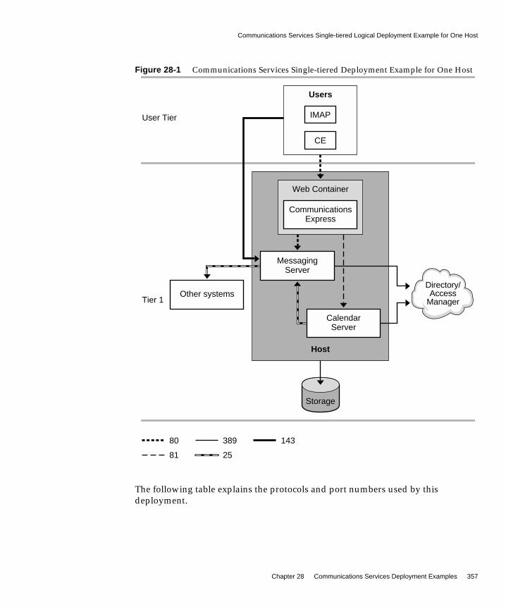
Communications Services Single-tiered Logical Deployment Example for One Host
Chapter 28 Communications Services Deployment Examples 357
Figure 28-1 Communications Services Single-tiered Deployment Example for One Host
The following table explains the protocols and port numbers used by thisdeployment.
Tier 1
User Tier
MessagingServer
Other systems
Users
CalendarServer
80
81
143389
25
Storage
Host
IMAP
CE
Directory/Access
Manager
CommunicationsExpress
Web Container
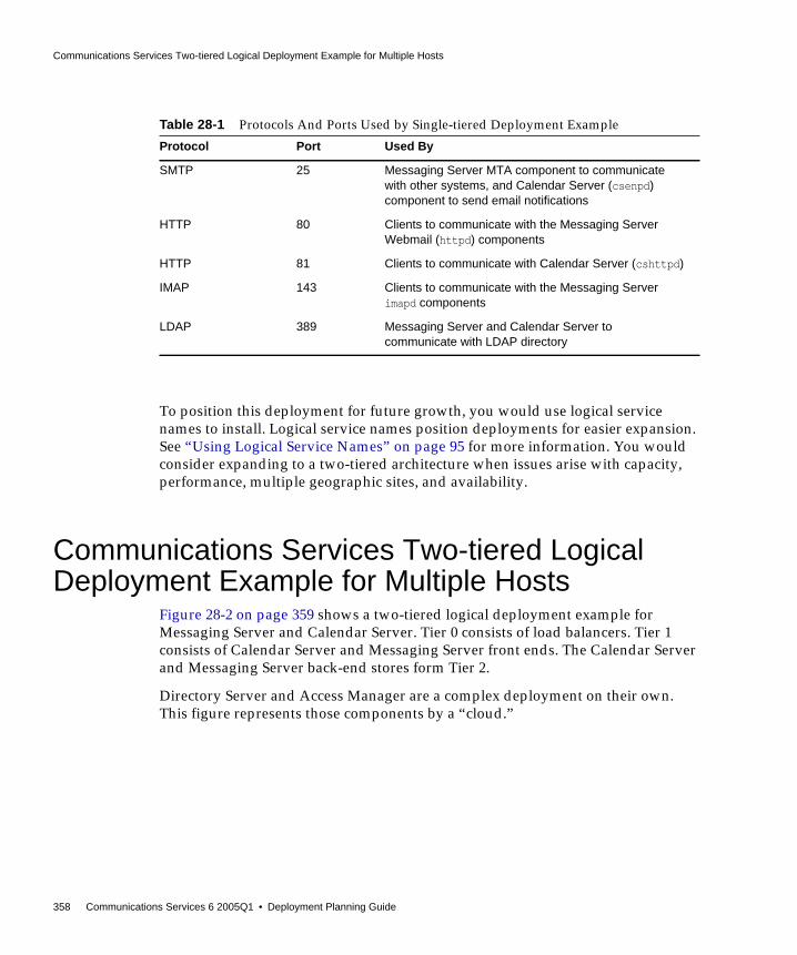
Communications Services Two-tiered Logical Deployment Example for Multiple Hosts
358 Communications Services 6 2005Q1 • Deployment Planning Guide
To position this deployment for future growth, you would use logical servicenames to install. Logical service names position deployments for easier expansion.See “Using Logical Service Names” on page 95 for more information. You wouldconsider expanding to a two-tiered architecture when issues arise with capacity,performance, multiple geographic sites, and availability.
Communications Services Two-tiered LogicalDeployment Example for Multiple Hosts
Figure 28-2 on page 359 shows a two-tiered logical deployment example forMessaging Server and Calendar Server. Tier 0 consists of load balancers. Tier 1consists of Calendar Server and Messaging Server front ends. The Calendar Serverand Messaging Server back-end stores form Tier 2.
Directory Server and Access Manager are a complex deployment on their own.This figure represents those components by a “cloud.”
Table 28-1 Protocols And Ports Used by Single-tiered Deployment Example
Protocol Port Used By
SMTP 25 Messaging Server MTA component to communicatewith other systems, and Calendar Server (csenpd)component to send email notifications
HTTP 80 Clients to communicate with the Messaging ServerWebmail (httpd) components
HTTP 81 Clients to communicate with Calendar Server (cshttpd)
IMAP 143 Clients to communicate with the Messaging Serverimapd components
LDAP 389 Messaging Server and Calendar Server tocommunicate with LDAP directory

Communications Services Two-tiered Logical Deployment Example for Multiple Hosts
Chapter 28 Communications Services Deployment Examples 359
Figure 28-2 Communications Services Two-tiered Deployment Example
Tier 1
Tier 2
Tier 0
User Tier
Msg FEs/MTAs
MTA
MMP
MEM
Cal FEs
csadmind
cshttpd
Cal BEs
csadmind
csnotifyd
enpd
csdwpd
Msg BEs
imapd
mshttpd
MTA
stored
8081
80
143
25
389
225
9779
LoadBalancers
SMTPRelay
Users
Directory/Access
Manager
SAN
Internal/external delivery
SharedStorage

Communications Services Two-tiered Logical Deployment Example for Multiple Hosts
360 Communications Services 6 2005Q1 • Deployment Planning Guide
In the preceding example, load balancers form Tier 0, and direct user access to thefront-end services.
The front-end services consist of four machines. Two machines are installed withCalendar Server front-end components. These Calendar Server front-end machinesconsist of one or two CPU servers and their own internal disk storage. Two othermachines are configured as Messaging Server proxies and MTAs, and share anexternal disk array. These Messaging Server machines consist of four CPU servers.
The back end also consists of four machines. Two machines serve as mail storesand run the Messaging Server processes. Two other machines serve as the calendarstores and run Calendar Server process. The store machines are attached to aStorage Area Network (SAN). These back-end machines can be deployed in avariety of ways, based upon your CPU needs. Once you determine the totalnumber of CPUs, you can opt for a vertical or horizontal configuration. Forexample, if your architecture called for a total of twelve CPUs, you could use threefour-way servers, two six-way servers, or even one 12-way server.
Another machine serves as an SMTP relay for both Calendar Server notificationsand Messaging Server emails.
The following table explains the protocols and port numbers used by thisdeployment.
Table 28-2 Protocols And Ports Used by Two-tiered Deployment Example
Protocol Port Used By
HTTP 80 Clients to communicate with the Messaging ServerMEM and Webmail (httpd) components
SMTP 25 Clients to communicate with the Messaging Server MTAcomponent, MTA components on the front end andback end, and Calendar Server (csenpd) componentsfor email notifications
IMAP 143 Clients to communicate with the Messaging ServerMMP and imapd components
LMTP 225 MTA routes email directly from the front end to theMessage Store on the back end, bypassing theback-end MTA
LDAP 389 Front ends and back ends to communicate with LDAPdirectory
HTTP 8081 Clients to communicate with Calendar Front End(cshttpd)
DWP 9779 Calendar front end (cshttpd) to communicate withCalendar back end (csdwpd)

361
Glossary
Refer to the Java Enterprise System Glossary (http://docs.sun.com/doc/816-6873) fora complete list of terms that are used in this document.

362 Communications Services 6 2005Q1 • Deployment Planning Guide
363
Index
SYMBOLS/opt/SUNWcomds/sbin directory 278/var/mail system 142, 143
AAccess Control Instructions 188Access Control Lists 62access controls 209, 225, 227, 228access layer 56, 57, 86, 91, 112, 164, 167, 171, 174, 305,
307Access Manager 260
CLI utilities 123Communications Express and 37deploying 253, 255, 318Instant Messaging Service Definition 283integration with Calendar Server 261integration with Instant Messaging 37Portal server and 322schema issues 39, 61, 151SSO 61, 120, 318user entry provisioning 138
ACIs 188address book 37, 39, 65, 71, 339, 340, 341, 343address book lookup 56address book module 343address verification for anti-spam 226Administration Server
configuration parameters 237
console 143installation worksheet 239upgrading concerns 236
alerts 33, 281, 292, 313, 322, 326anti-spam
access control 226authentication service 226comprehensive tracing 226deployment issues 230deployment scenarios 232integrating with third-party products 230mailbox filtering 226message address verification 226overview 225Real-time Blackhole List 226relay blocking 226sidelining 226
anti-virusconversion channel 226deployment issues 230deployment scenarios 232integrating with third-party products 230overview 225
applet URL 314, 322application security 113architectural strategies 164, 202, 305architecture
one-tiered 164, 165, 306, 307two-tiered 88, 164, 165, 305, 306, 307
ASR 98, 182assessing security needs 110authentication

Section B
364 Communications Services 6 2005Q1 • Deployment Planning Guide
Access Manager and 320DWP and 262LDAP and 284load on Calendar Server 66, 266planning for users 218Portal Server and 324protecting the Message Store 217SASL 219, 228server security 111SMTP 220SSL 221, 263users and 284validating roaming users 233
authentication services for Messaging Server 228automatic system reconfiguration 98
Bbackup and recovery 163balancing network connections 171benefits
Calendar Server 246Communications Services summary 37directory server replication 99one-tree DIT structure 58single-tiered architecture 90two-tiered architecture 91
Brightmail 214, 230, 232business requirements 31, 46
Ccalendar alerts 282, 292, 315, 317calendar event notification, See event notificationCalendar Server 273
Administration Service 265and Directory Server interaction 64and high availability 101and Instant Messaging 284authentication 66, 266back-end system 266
benefits 246Calendar Express 33, 39, 64, 69, 250, 255, 257, 260client-side rendering 278configuration examples 256configuration program 278considerations 66, 265creating a deployment team 249default time zone 278Distributed Database Service 265end users 249Event Notification Service 265high availability 67hosted domains 276, 350HTTP Service 265installing components 274LDAP data cache 268Master/slave LDAP configuration 269migrating data 70monitoring your system 262Notification Service 265overview 33password 263planning for user authentication 263plugins 246post-installation configuration 277satisfying business needs 36security 263services 265support for industry standards 246
Calendar Store 56capacity planning 50, 64, 90central topology 190, 192, 194, 196CERT 117certificate 115, 139, 220, 221, 223, 263certificate authorities 115, 222changes in DIT structure 57channel programs
master 144slave 144, 146
channelsconfiguring 145conversion 143, 213default 143defragmentation 143filter 213keywords 145
Section D
Index 365
LMTP 143local 143overview 143pipe 143reprocessing 143SMTP 143
chat 33, 281, 290, 291, 300cipher 223CLI utilities
Access Manager 123Calendar Server 123, 276Message Store 150MTA 140Sun ONE Delegated Administrator 127
client access filter 215cn attribute 284comm_dssetup.pl script 237, 238, 276, 277commadmin utility 255Communications Express
address book 71, 339, 341, 343address book module 343considerations 71installation considerations 349overview 34product features 340S/MIME 71, 350, 351satisfying business needs 37scaling 68user preferences 340web container 341
Communications Servicesand Portal Server 39business requirements 31components 56deployment process 40examples 343, 355high availability 38logical architectures 81overview 31satisfying business needs 36summary of benefits 37
compatibility mode, Schema 2 122, 125component product planning aspects 54comprehensive tracing 229Computer Emergency Response Team 117
concurrent connections 156conference rooms 34, 246, 281, 290, 291configuration parameters 237Connector for Microsoft Outlook
considerations 69overview 35product dependencies 70
contention between servers 235conversion channel 143, 213, 226, 229corporate directory 56, 57CPU requirements 164, 188CRAM-MD5 217, 219csconfigurator.sh script 278
Ddata layer 56, 82, 112, 164, 167, 170, 171, 305, 307, 342Database Wire Protocol 254, 256, 257, 259db_stat command 185DC tree 58, 60, 120, 123default time zone 278defining
Instant Messaging site profile 300Instant Messaging user base 300Messaging Server user base 159
defragmentation channel 143Delegated Administrator 121, 124, 126, 128, 129, 131,
137, 142, 255, 276, 277, 349description 172provisioning options 126Schema 1 and 61, 137
demilitarized zone 77, 87, 199denial of service 90, 91, 110, 165, 166, 167, 168, 172,
188, 208, 307deployment
considerations 94examples 311, 343, 355goals 45process 40
determining project goals 50Digest-MD5 217, 219Directory Information Tree 57, 62, 150
Section E
366 Communications Services 6 2005Q1 • Deployment Planning Guide
Directory Proxy Server 102, 103Directory Server
and Personal Address Book considerations 65capacity planning 64considerations 62description 150high availability and 99installation worksheet 237replica role promotion 103replication ability 151tiered architecture considerations 63topology considerations 63
Directory Server Setup script 277disaster recovery 49, 158, 163, 300disk
calculating throughput 162determining amount 163
disk stripe width 185Distributed Database Service 265distributed topology 192DIT 57, 62, 150DIT structure 57, 58DMZ 77, 87DNS 48, 74, 76, 83, 215DNS server, purpose 142, 171domain
hosted 38, 137rewrite rules 145structure 57vanity 137
DWP 254, 256, 257, 278, 360
Eedge logical architecture 82, 88, 90EHLO 116, 117email
Instant Messaging and 284notification 315
embedded URLs 292encrypted mail 221, 222, 263end-user filter 213
end-user performance 250equation to calculate system availability 49event notification 284Event Notification Service 265existing infrastructure 48Extensible Messaging and Presence Protocol 34
Ffiltering
client access 139for end-user 213for unsolicited mail 139FROM_ACCESS 210MAIL_ACCESS mapping table 209mapping table 209ORIG_MAIL_ACCESS mapping table 210ORIG_SEND_ACCESS 209PORT_ACCESS 210SEND_ACCESS mapping table 209
financial requirements 49firewall
configuration 79DMZ segmentation 78network address translation 117purpose 75
freeware mail filter 214FROM_ACCESS 210
Ggateway 202, 261, 285, 334
Hheavyweight POP users 160high availability
automatic system reconfiguration 98Calendar Server 67, 101

Section I
Index 367
Communications Services 38description 179Messaging Server 101overview 98
horizontal scalability 93, 175, 256hosted domains 137, 276, 350HTTP Service for Calendar Server 265hybrid topology 194
Iics.conf configuration file 278Identd callback 215identifying deployment goals 45iim.conf file 298, 302iim.jvm.maxmemorysize parameter 302iim_mux.maxsessions parameter 298, 305iim_mux.maxthreads parameter 304iim_mux.numinstances parameter 298, 305IMAP 20, 95, 139, 142, 155, 167, 171, 172, 174, 180,
206, 211, 215, 218, 219, 221, 228imbrand.jar file 283imdesktop.jar file 283imjini.jar file 283imnet.jar file 283implementing secure connections 114imres.jar file 283imsbackup command 163imta.cnf file 145inbound and outbound message traffic 178INBOX 148, 149incoming messages
MTAs 177relays 198routing by MTA 142
index.html file 283instant message
embedded URLs in 292structure 286
Instant MessagingAccess Manager and 318
Access Manager requirements 285Access Manager SDK requirements 285alerts 33, 281, 292, 313, 322, 326API 283architectural strategies 305archive 303, 304, 322as a channel in Portal Server 285assign services to existing users parameter 333basic architecture 288basic deployment 313Calendar Server requirements 284casual users 300chat 281, 290, 291collecting sizing data 296conference rooms 281, 290, 291configuring instance as multiplexor 333considerations 68core components 282, 290CPU resources 304database 284defining usage profile 297deploying multiple servers 329deployment examples 311direct LDAP lookup 290disabling server parameter 333disk capacity 303disk throughput 302email and 284heavy users 300installation directory parameter 332Instant Messenger 291LDAP requirements 284load balancers 308load simulator 301maximum memory for JVM 302memory utilization 302message delivery 290Messaging server and 315multiplexor 282, 290network throughput 303news channels 292offline message forwarding 284overview 33peak volume defined 296performance guidelines 301platform options 311polls 281, 292

Section J
368 Communications Services 6 2005Q1 • Deployment Planning Guide
Portal Server and 322Portal Server requirements 285Portal Server Secure Remote Access
requirements 285protocols 283proxy 56related components 283resource requirements 308satisfying business needs 37server defined 282server domain name parameter 333server host name parameter 333server port number parameter 333SMTP requirements 284SMTP server and 315SSO 318supported standards 286tuning iim.conf settings for multiplexor 298tuning rules of thumb 304user base defined 300web server requirements 283Webmail 90
Instant Messaging deploymentAccess Manager and 318authentication and 320, 324email notification and 315multiple Instant Messaging servers 329physical 327Portal server and 322SMTP server and 315
Instant Messaging filesiim.conf 302imbrand.jar 283imdesktop.jar 283imjini.jar 283imnet.jar 283imres.jar 283index.html 283
Instant Messaging multiplexorbest practices 304configuration 304configuring 333core component 282deploying multiple 328port number parameter 333resource requirements and 328Windows support and 328
Instant Messenger 291applet URL 314, 322communication modes 291non-secure mode 285secure mode 285
Instant Messenger resourcesfiles 283installing 283Web server and 283
internal network 78Internet Relay 198, 205intranet 78IP-spoofing, protecting against 79ISDN 73
JJava Enterprise System installer 235, 237, 239, 240,
273, 274, 278, 331Java plugin 314, 322, 326Java Web Start 291, 292, 314, 322, 326JavaScript 92, 342, 349JavaServer Pages 342junk mail 208, 211
LLDAP
attributes affecting master/slaveconfiguration 270
attributes for Instant Messaging 284attributes to index for performance 70CLD plugin 250considerations 63data cache and Calendar Server 268deployment culture and politics 47DIT requirements 57LMTP and 94load balancers and 102Master Server 64, 65one-tree structure 57

Section M
Index 369
provisioning 125, 129, 130, 138provisioning tools 128user attributes 284user authentication and 284using Calendar Server API for non-LDAP
directory server 255LDAP database
Messaging Server 135new groups 142new users 142
LDAP directoryfor user provisioning 137lookup 145purpose 142, 171tools 126
LDAP Schema 1 61, 137LDAP Schema 2 61, 137, 277Legato Networker 163lightweight IMAP users 160lightweight POP users 160limiting network access 113limiting physical access to hardware 111Linux
default base directory for 24Instant Messaging default directory for logs 335Instant Messaging default installation
directory 332Instant Messaging setup program 331
LMTP 91, 94, 360load balancer 102, 267load balancing 75, 76, 90, 92, 99, 102, 136, 166, 178,
250, 307, 308load simulator
Instant Messaging 301Messaging Server 161
local channel 143Local Mail Transfer Protocol
delivery mechanism 241implementing 94multi-tier deployment 147offloading SMTP processing 91
local.servergid parameter 275local.serveruid parameter 275log file directory, Message Store 182
logical architectureedge 88single-tiered distributed 84single-tiered for multiple hosts 83single-tiered for one host 82two-tiered 86
logical service names 95
MMail Abuse Protection System’s Read-time Blackhole
List 214mail filter 211
client access 215conversion channel 213DNS lookup 215for a channel 213for a user 212for mailbox 212for Message Transfer Agent 213Identd callback 215MAPS RBL 214server-side rules 212Sieve 213SpamAssassin 214
MAIL_ACCESS mapping table 209, 210mailAlternateAddress attribute 137mailbox
database files 181Message Store and 148Messaging Multiplexor and 172Messenger Express Multiplexor and 172optimization 184setting database cache size 184
mailbox filtering 226, 227mailEquivalentAddress attribute 137MAPI 35mapping tables to filter mail 209MAPS RBL 94master programs, channels 143Master/slave LDAP 269mboxlist directory 182mediumweight IMAP users 160
Section M
370 Communications Services 6 2005Q1 • Deployment Planning Guide
mediumweight Messenger Express users 161memory
large Instant Messaging deployment 309minimum requirement for Instant Messaging 302minimum requirement for Messaging Server 162small Instant Messaging deployment 308
message address verification 227Message Store 56
configuring 140definition 142description 148determining size 166folders 148HTTP 142IMAP 142, 148IMAP server 171installing 240log file directory 182Messaging Multiplexor 172partitions 149, 183performance issues 180POP 142, 148POP server 171recovering lost data 149scaling 184security issues 216single-copy message store 149sizing 163system files 148user mailboxes 148
Message Transfer Agentaccess component 56configuring 140incoming email messages 172installing 240Internet-facing 199mail filter 213managing messages 142MX records 177outgoing email messages 172performance issues 185protecting relays 207purpose 141, 143queue directories 181service dispatcher 210single-tiered architecture 83SMTP protocol 141
two-tiered architecture 86Messaging API 35Messaging Express Multiplexor 86, 92Messaging Multiplexor 56, 83, 86, 172
high availability 187performance issues 187
Messaging ServerAdministration Server console 143and high availability 101authentication services 228considerations 65determining concurrent connections 156disable sendmail daemon 241dividing clients across multiple hosts 175firewall 78hosted domains 137installation directory 236installation privileges 235installation worksheet 237installing 235, 236, 240, 241LDAP database 135, 137load balancing 75, 178Local Mail Transfer Protocol 147log file directory 182message load for a server machine 178Message Transfer Agent 83, 86Messaging Express Multiplexor 86Messaging Multiplexor 83mobile users 80overview 32performance issues 179port number conflicts 236resource contention 235satisfying business needs 36Schema 1 151Schema 2 151Secure Sockets Layer 221, 222security features 139sizing Message Store 163spam 91standalone view 140supported protocols 136two-tiered architecture 164, 165, 169unified messaging solution 138Webmail 114, 340
messaging topology 189

Section N
Index 371
Messenger Express 65, 71, 83, 84, 85, 87, 113, 127,156, 164, 171, 212, 213, 218, 219, 221, 227, 236, 240,343description 172encryption 224S/MIME 224security issues 217signed messages 224
Messenger Express Multiplexorperformance issues 188purpose 200
messenger.jar file 283Microsoft Exchange Server data 70Microsoft Outlook 35, 56, 69, 85, 87, 250migrating data 70MIME messages 143MMP 172
installing Messenger Express 240security issues 217
mobile users 80monitoring your system 216, 262MTA router 166MX records 177
NNetlet
Instant Messaging port number parameter 334secure mode 285
networkbalancing connections 171demilitarized zone 77firewall 75infrastructure components 74internal 78limiting access 113mobile users 80planning infrastructure layout 77proxy 79routers 74switch 75throughput issues 163Virtual Private Networking 194
WAN 104, 194network address translation 117news channels 292non-secure mode,Instant Messenger 285NOTARY 116Notification Service 265
Ooffline message forwarding 284one-tiered architecture
description 167Instant Messaging 307security issues 217
operating system security 112operation requirements 46Organization Tree 58, 120, 123ORIG_MAIL_ACCESS mapping table 210ORIG_SEND_ACCESS 209outbound and inbound message traffic 178outgoing mail messages 142overview
Calendar Server 33Communications Express 34Communications Services 31Connector for Microsoft Outlook 35Instant Messaging 33logical architectures 81Messaging Server 32Sun ONE Synchronization 34
Pparameters
iim.jvm.maxmemorysize 302iim_mux.maxsessions 298, 305iim_mux.maxthreads 304iim_mux.numinstances 298, 305Instant Messaging multiplexor port number 333Instant Messaging secure mode 334Instant Messaging server domain name 333
Section R
372 Communications Services 6 2005Q1 • Deployment Planning Guide
Instant Messaging server host name 333Instant Messaging server port number 333Netlet Instant Messaging port number 334remote Instant Messaging server host name 333
passwordCRAM-MD5 219encrypted 219, 263issues 218, 263plain text 219, 263SASL 219
peak volumedefining for Instant Messaging 296determining for Messaging Server 154
performanceguidelines for Instant Messaging 301Message Store 180Message Transfer Agent 185Messaging Multiplexor 187Messaging Server issues 179Messenger Express Multiplexor 188
Personal Address Book 65, 171physical access to hardware 111physical deployment examples 327pipe channel 143planning installation and configuration 273policy management 318polls 33, 281, 292POP 20, 95, 139, 142, 155, 158, 167, 171, 172, 174, 180,
187, 206, 211, 215, 218, 219, 221, 228port number conflicts 236port numbers
Communications Express remote hostdeployment example 345, 348
conflicting in Messaging Server 236Instant Messaging multiplexor 333Instant Messaging server 333single-tiered Communications Services
deployment example 358two-tiered Communications Services deployment
example 360PORT_ACCESS 210Portal Server
Access Manager and 322and Communications Services 39considerations 69
Desktop 40, 285Instant Messaging deployment and 322Netlet 285Secure Remote Access 40
post-installation configuration 277premium broadband users 160private backup network 302private key 221, 263program channels, master 147project goals 50protecting MTAs 207protecting software 111protocols
Instant Messaging and 283public 171supported by Messaging Server 136
provisioning optionsdeciding on schema version 120, 123Delegated Administrator 126LDAP directory tools 126, 129provisioning tools 125, 129tool comparisons 127, 130
provisioning users 137proxy 79public access protocols 171public key 221, 263
RReal-time Blackhole List 94, 226, 228reducing hardware downtime 98relay blocking 226, 228remote Instant Messaging server host name
parameter 333remote site failover 104, 106replica role promotion 103reprocessing channel 143requirements
business 46culture and politics 46financial 49Instant Messenger resources 283
Section S
Index 373
operation 46schema 61technical 47
residential dial-up 160resource contention 235retrieving mail, internal user 174reverse DNS 91Reverse DNS lookups 215rewrite rules
example 145message header 145purpose 145transport layer 145
roaming users 233routers 74
SS/MIME 71, 114, 350, 351S/MIME messages 224SAML 114SAN 76SASL 219scaling
Communications Express 68front-end and back-end services 93Messaging Store 184
schemachoosing 120requirements 61
Schema 1 39, 61, 137Calendar Server support 122Delegated Administrator 121, 124, 126description 120, 123Messaging Server support 120, 151requirements 61
Schema 2 39, 61, 277Access Manager 126, 129choosing 120, 123compatibility mode 122, 125Messaging Server support 151native mode 121, 124requirements 61
support 137schema versions, choosing 123secure connections 114secure mode
Instant Messaging parameter 334Instant Messenger 285
Secure Sockets Layer 263access control 139cipher 223encryption 222hardware accelerator 187Messaging Server 221SASL 219
Secure/Multipurpose Internet Mail Extension 71security
application 113assessing needs 110cipher 223Computer Emergency Response Team 117CRAM-MD5 219Digest-MD5 219encryption 222, 224hiding IP addresses 116hiding product names and versions 116limiting access to network 113limiting physical access to hardware 111message store 216Messenger Express 217misconceptions 116MMP 217network address translation 117not using EHLO 116NOTARY 116one-tiered architecture 217operating system 112password 218protecting MTA relays 207protecting software 111protocols 139SASL 219Secure Sockets Layer 219, 221, 222, 263server 111signatures 224SMTP AUTH 217, 220TLS negotiation 116two-tiered architecture 217

Section T
374 Communications Services 6 2005Q1 • Deployment Planning Guide
security features 139SEND_ACCESS mapping table 209, 210sending mail
internal user to internal user 173internal user to internet user 174internet user to internal user 174
sendmail daemon, disable 241server-side rules 212service level agreements 49service names 95service provider topology 196service tiers 55sidelining 226, 229Sieve, mail filter 213Simple Authentication and Security Layer 139Simple Mail Transport Protocol
authenticated 220channel 143gateway 202purpose 142SMTP AUTH 217
single sign-on 61, 255, 318single-copy message store 149single-tiered architecture
benefits 90distributed 84for multiple hosts 83overview 81
site distribution 48site failover 300site profile 300sizing
collecting Instant Messaging data 296collecting Messaging Server data 154components in single-tiered or two-tiered
architectures 88Instant Messaging multiplexors 306Message Store 163MMP 187
SLAs 49slave program, channels 144SMTP AUTH 211, 220snapshot function 149Solaris
patches 26support 26
Solaris Fingerprint Database 112Solaris Security Toolkit 75, 112Solid State Disks 182Solstice Backup 163Solution Life Cycle 40spam
Brightmail products 214Messaging Server 91protecting against 213SpamAssassin 214
SpamAssassin 230, 232spoofing 208SSL 86, 90, 91, 114, 115SSL/TLS 114SSO 61standards, supported by Instant Messaging 286Storage Area Network 56, 76store.dbcachesize parameter 184strategy for scalability 93structure, instant message 286Sun Cluster software 39, 63, 67, 98, 100, 101, 104, 107,
249, 267Sun ONE Synchronization 34, 250support personnel 48supporting existing usage patterns 47switches 48, 75Symantec AntiVirus Scan Engine 233Symantec Brightmail 230, 232
TTCO 51technical requirements 47TLS negotiation 116tools
comparisons 127, 130provisioning 125, 129
topologycentral 190

Section U
Index 375
components 198designing 189distributed 192example 202hybrid 194service provider 196
total cost of ownership 51Transport Layer Security 139Tripwire for Servers 112two-tiered architecture 82, 86, 91, 305
access layer 170advantages 165data layer 170description 164overview 81performance 217questions about 48
Uuid attribute 284unauthorized mail relaying 208understanding
business requirements 46Calendar Server pre-installation
requirements 273Communications Express pre-installation
requirements 349Instant Messaging pre-installation
requirements 331Messaging Server pre-installation
requirements 235Messaging Server topology elements 197remote site failover 104schema and provisioning options 119service tiers 55
upgrading Administration Server 236uptime calculation 49URL
embedded in instant message 292Instant Messaging applet 314Instant Messaging code base 336
usage patterns 47, 62, 166
usage profiledefining for Instant Messaging 297determining for Messaging Server 154
usersauthenticating in LDAP 284heavyweight POP 160lightweight IMAP users 160lightweight POP 160mediumweight IMAP 160mediumweight Messenger Express 161
Vvanity domains 137Veritas Cluster Server software 38, 98, 101Veritas software
documentation 104high availability 107
vertical scalability 178Virtual Private Networking 194virus
Brightmail products 214protecting against 213
VPN 73, 77, 194, 217
WWABP 35WAN 104, 194Web Address Book Protocol 35web container 71, 100, 187, 318, 339, 341, 343, 345,
349Web Server
installing with Instant Messaging 327Instant Messenger resources and 283
Webmail 84, 90, 114, 139, 172, 182, 340, 358, 360worksheet
configuring the Administration Server 239for installing Directory Server 237for installing Messaging Server 237

Section X
376 Communications Services 6 2005Q1 • Deployment Planning Guide
XX.509 format 350Ximian Evolution 38XMPP 34, 37


![Sun Java[TM] System Identity Installation Pack 2005Q4M3 ... · Sun Java™ System Identity Installation Pack 2005Q4M3 SP3 Release Notes Sun Microsystems, Inc. 4150 Network Circle](https://static.fdocuments.in/doc/165x107/5e8532b585f2877d2b292a8f/sun-javatm-system-identity-installation-pack-2005q4m3-sun-javaa-system-identity.jpg)